US8753289B2 - Pricking system - Google Patents
Pricking systemDownload PDFInfo
- Publication number
- US8753289B2 US8753289B2US12/619,420US61942009AUS8753289B2US 8753289 B2US8753289 B2US 8753289B2US 61942009 AUS61942009 AUS 61942009AUS 8753289 B2US8753289 B2US 8753289B2
- Authority
- US
- United States
- Prior art keywords
- pricking
- movement
- sampling
- coupling part
- end position
- Prior art date
- Legal status (The legal status is an assumption and is not a legal conclusion. Google has not performed a legal analysis and makes no representation as to the accuracy of the status listed.)
- Expired - Fee Related, expires
Links
Images


Classifications
- A—HUMAN NECESSITIES
- A61—MEDICAL OR VETERINARY SCIENCE; HYGIENE
- A61B—DIAGNOSIS; SURGERY; IDENTIFICATION
- A61B5/00—Measuring for diagnostic purposes; Identification of persons
- A61B5/15—Devices for taking samples of blood
- A61B5/151—Devices specially adapted for taking samples of capillary blood, e.g. by lancets, needles or blades
- A—HUMAN NECESSITIES
- A61—MEDICAL OR VETERINARY SCIENCE; HYGIENE
- A61B—DIAGNOSIS; SURGERY; IDENTIFICATION
- A61B5/00—Measuring for diagnostic purposes; Identification of persons
- A61B5/15—Devices for taking samples of blood
- A61B5/157—Devices characterised by integrated means for measuring characteristics of blood
- A—HUMAN NECESSITIES
- A61—MEDICAL OR VETERINARY SCIENCE; HYGIENE
- A61B—DIAGNOSIS; SURGERY; IDENTIFICATION
- A61B5/00—Measuring for diagnostic purposes; Identification of persons
- A61B5/15—Devices for taking samples of blood
- A61B5/150007—Details
- A61B5/150015—Source of blood
- A61B5/150022—Source of blood for capillary blood or interstitial fluid
- A—HUMAN NECESSITIES
- A61—MEDICAL OR VETERINARY SCIENCE; HYGIENE
- A61B—DIAGNOSIS; SURGERY; IDENTIFICATION
- A61B5/00—Measuring for diagnostic purposes; Identification of persons
- A61B5/15—Devices for taking samples of blood
- A61B5/150007—Details
- A61B5/150175—Adjustment of penetration depth
- A—HUMAN NECESSITIES
- A61—MEDICAL OR VETERINARY SCIENCE; HYGIENE
- A61B—DIAGNOSIS; SURGERY; IDENTIFICATION
- A61B5/00—Measuring for diagnostic purposes; Identification of persons
- A61B5/15—Devices for taking samples of blood
- A61B5/150007—Details
- A61B5/150358—Strips for collecting blood, e.g. absorbent
- A—HUMAN NECESSITIES
- A61—MEDICAL OR VETERINARY SCIENCE; HYGIENE
- A61B—DIAGNOSIS; SURGERY; IDENTIFICATION
- A61B5/00—Measuring for diagnostic purposes; Identification of persons
- A61B5/15—Devices for taking samples of blood
- A61B5/150007—Details
- A61B5/150374—Details of piercing elements or protective means for preventing accidental injuries by such piercing elements
- A61B5/150381—Design of piercing elements
- A61B5/150412—Pointed piercing elements, e.g. needles, lancets for piercing the skin
- A—HUMAN NECESSITIES
- A61—MEDICAL OR VETERINARY SCIENCE; HYGIENE
- A61B—DIAGNOSIS; SURGERY; IDENTIFICATION
- A61B5/00—Measuring for diagnostic purposes; Identification of persons
- A61B5/15—Devices for taking samples of blood
- A61B5/150007—Details
- A61B5/150374—Details of piercing elements or protective means for preventing accidental injuries by such piercing elements
- A61B5/150381—Design of piercing elements
- A61B5/150503—Single-ended needles
- A—HUMAN NECESSITIES
- A61—MEDICAL OR VETERINARY SCIENCE; HYGIENE
- A61B—DIAGNOSIS; SURGERY; IDENTIFICATION
- A61B5/00—Measuring for diagnostic purposes; Identification of persons
- A61B5/15—Devices for taking samples of blood
- A61B5/151—Devices specially adapted for taking samples of capillary blood, e.g. by lancets, needles or blades
- A61B5/15101—Details
- A61B5/15115—Driving means for propelling the piercing element to pierce the skin, e.g. comprising mechanisms based on shape memory alloys, magnetism, solenoids, piezoelectric effect, biased elements, resilient elements, vacuum or compressed fluids
- A61B5/15117—Driving means for propelling the piercing element to pierce the skin, e.g. comprising mechanisms based on shape memory alloys, magnetism, solenoids, piezoelectric effect, biased elements, resilient elements, vacuum or compressed fluids comprising biased elements, resilient elements or a spring, e.g. a helical spring, leaf spring, or elastic strap
- A—HUMAN NECESSITIES
- A61—MEDICAL OR VETERINARY SCIENCE; HYGIENE
- A61B—DIAGNOSIS; SURGERY; IDENTIFICATION
- A61B5/00—Measuring for diagnostic purposes; Identification of persons
- A61B5/15—Devices for taking samples of blood
- A61B5/151—Devices specially adapted for taking samples of capillary blood, e.g. by lancets, needles or blades
- A61B5/15101—Details
- A61B5/15126—Means for controlling the lancing movement, e.g. 2D- or 3D-shaped elements, tooth-shaped elements or sliding guides
- A61B5/15128—Means for controlling the lancing movement, e.g. 2D- or 3D-shaped elements, tooth-shaped elements or sliding guides comprising 2D- or 3D-shaped elements, e.g. cams, curved guide rails or threads
- A—HUMAN NECESSITIES
- A61—MEDICAL OR VETERINARY SCIENCE; HYGIENE
- A61B—DIAGNOSIS; SURGERY; IDENTIFICATION
- A61B5/00—Measuring for diagnostic purposes; Identification of persons
- A61B5/15—Devices for taking samples of blood
- A61B5/151—Devices specially adapted for taking samples of capillary blood, e.g. by lancets, needles or blades
- A61B5/15101—Details
- A61B5/15126—Means for controlling the lancing movement, e.g. 2D- or 3D-shaped elements, tooth-shaped elements or sliding guides
- A61B5/1513—Means for controlling the lancing movement, e.g. 2D- or 3D-shaped elements, tooth-shaped elements or sliding guides comprising linear sliding guides
- A—HUMAN NECESSITIES
- A61—MEDICAL OR VETERINARY SCIENCE; HYGIENE
- A61B—DIAGNOSIS; SURGERY; IDENTIFICATION
- A61B5/00—Measuring for diagnostic purposes; Identification of persons
- A61B5/15—Devices for taking samples of blood
- A61B5/151—Devices specially adapted for taking samples of capillary blood, e.g. by lancets, needles or blades
- A61B5/15146—Devices loaded with multiple lancets simultaneously, e.g. for serial firing without reloading, for example by use of stocking means.
Definitions
- the present inventionrelates to the field of pricking systems.
- Pricking systemsare used, for example, by diabetics who have to check their blood-sugar level several times a day and who need for that purpose a sample of body liquid, as a rule of blood or interstitial liquid that is gained from a prick wound produced by a pricking system.
- pricking systemswhere one and the same appliance is used for producing a prick wound and for collecting a sample from a prick wound so produced.
- Automatic samplingmakes it easier for a user to analyze a sample of body liquid, which is a considerable advantage especially for persons whose manual mobility is impaired by age or illness.
- automatic samplingreduces the risk of contamination of samples, which otherwise might lead to distortion of the measuring results.
- a drive of the pricking systemis coupled, via a coupling element, with a lancet for a pricking movement and with a sampling device for a sampling movement. Accordingly, the coupling part is moved during each pricking movement and each sampling movement, respectively, from a starting position to an end position by an advancing movement, and then back from the end position to the starting position by a reversing movement.
- the sampling deviceshould be guided for a sampling operation as precisely as possible to the prick wound that has been produced before by a pricking movement, it has been found as part of the invention that identical movements of the coupling part in a sampling movement and a pricking movement are neither necessary nor advantageous. Surprisingly, efficient sampling can be achieved when the end position reached by the coupling part in a sampling movement differs from the end position reached by the coupling part in a pricking movement.
- FIG. 1shows an embodiment of a pricking system according to the invention
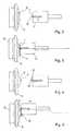
- FIG. 2shows a diagrammatic representation of the position of a coupling part with a lancet, relative to a body part brought into contact with an appliance opening, prior to a pricking operation;
- FIG. 3shows a representation according to FIG. 2 , at the moment a body part is pricked by the lancet;
- FIG. 4shows a representation according to FIG. 2 , prior to a sampling operation
- FIG. 5shows a representation according to FIGS. 2 to 4 at the moment of a sampling operation
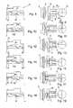
- FIG. 6shows a diagrammatic representation, of an embodiment of a motion control adapted to generate different motion profiles for the coupling part
- FIG. 7shows the embodiment illustrated in FIG. 6 , at the moment of a sampling operation
- FIG. 8shows another embodiment of a motion control, in the condition immediately before a pricking operation
- FIG. 9shows a diagrammatic cross-sectional representation of the pricking system, prior to a pricking operation, according to FIG. 8 ;
- FIG. 10shows a representation according to FIG. 8 during a pricking operation
- FIG. 11shows a representation according to FIG. 9 during a pricking operation
- FIG. 12shows a representation according to FIG. 10 , immediately after a pricking operation has been performed
- FIG. 13shows a representation according to FIG. 11 , immediately after a pricking operation has been performed
- FIG. 14shows a representation according to FIG. 8 , prior to a sampling movement
- FIG. 15shows a representation according to FIG. 13 , prior to a sampling movement
- FIG. 16shows a representation according to FIG. 14 , at the moment, of a sampling operation
- FIG. 17shows a representation according to FIG. 15 , at the moment of a sampling operation
- FIG. 18shows a representation according to FIG. 16 , after a sampling operation
- FIG. 19shows a representation according to FIG. 17 , after a sampling operation
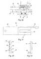
- FIG. 20shows a cross-sectional view of another embodiment of a motion control
- FIG. 21shows a top view, taken in the pricking direction, of the motion control of FIG. 20 ;
- FIG. 22shows a front view of the embodiment of FIG. 20 ;
- FIG. 23shows a rear view of the embodiment of FIG. 20 ;
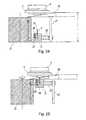
- FIG. 24shows another embodiment with a coupling part in a starting position for a pricking movement
- FIG. 25shows a representation according to FIG. 24 , with the coupling part in its end position of a pricking movement
- FIG. 26shows a representation according to FIG. 24 , with a coupling part in its starting position for a sampling movement
- FIG. 27shows a representation according to FIG. 24 , with the coupling part in its end position of a sampling movement.
- FIG. 1shows one embodiment of a lancing instrument 1 according to the invention intended for collecting a sample of a body liquid.
- the lancing instrument 1comprises a housing 6 with a housing opening 2 against which a body area is pressed for producing a prick wound. Further, the lancing instrument 1 comprises operating elements 3 in the form of keys and a display 4 in the form of a liquid crystal display intended for displaying examination results.
- the pricking system 1comprises a multiple-use pricking device into which an exchangeable supply of lancets and test elements can be loaded.
- the pricking deviceis equipped with a receptacle (not shown) for an exchangeable supply of lancets and test elements.
- the receptaclehas an opening that can be closed, arranged on the back of the embodiment illustrated in FIG. 1 .
- the supply of lancets and test elements of the illustrated embodimentconsists in a carrier tape which carries a plurality of lancets between which test elements are arranged for examination of a sample of a body liquid.
- the test elementscontain for example test chemicals which, when brought into contact with an analyte to be detected, for example glucose, produce a change in color that can be recorded photometrically. Electrochemical sample testing, for example, is likewise possible.
- the carrier tapeis moved by a transport facility in a feed direction so that the lancets and test elements can be sequentially moved to the correct position for use.
- the transport facilitymay comprise, for example, a winding device on which the carrier strip is wound up in a manner similar to a tape of a tape cassette.
- a carrier tapeas a supply of lancets and test elements
- other kinds of lancet and/or test element suppliessuch as rotary magazines, may be used as well.
- transport directionis understood to describe the longitudinal direction of the carrier tape along which the carrier tape must be transported to move unused lancets to the pricking position, and to remove used lancets from the pricking position.
- FIGS. 2 to 5show by way of a diagrammatic representation the manner in which a prick wound is produced by a lancet 7 in a body part 5 brought into contact with the housing opening 2 and, thereafter, a body liquid 8 issuing from the prick wound is collected using a sampling device 9 .
- the sampling device 9comprises a test field which, just the lancet 7 used for producing the prick wound, is arranged on a carrier tape 10 .
- FIG. 2shows a body part 5 , that has been brought into contact with the housing opening 2 , and a coupling part 11 which couples with a drive a lancet 7 for a pricking movement and, following the latter, a sampling device 9 for a sampling movement.
- the illustrated coupling part 11is provided with a gap through which is guided the carrier tape, carrying the lancets 7 and the test fields 9 .
- the lancets 7are arranged transversely to the longitudinal direction of the carrier tape 10 .
- FIG. 2shows a cross-sectional view of the coupling part 11 and the carrier tape 10 , with a lancet 7 located in the correct position for use, in which it can be moved together with the coupling part 11 for performing a pricking movement.
- the coupling part 11is moved in a pricking direction, which is indicated in FIG. 3 by a broken line.
- the carrier tape 10is bent in lengthwise direction so that the tip of the lancet 7 is lifted off the carrier tape 10 and pricks the body part 5 applied to the housing opening 2 , as illustrated in FIG. 3 .
- bending in lengthwise directionas used in this connection is meant to describe that the carrier tape is bent about a geometric bending axis that extends in lengthwise direction of the strip. Bending of the carrier tape in lengthwise direction, accordingly, has the effect that the two longitudinal edges of the carrier tape come to include between them an angle different from 180°, for example an angle of between 90° and 135°.
- the pricking movementcomprises an advancing movement by which the coupling part 11 is moved from the starting position illustrated in FIG. 2 to the end position illustrated in FIG. 3 .
- the coupling part 11is returned by a reversing movement to a starting position for a sampling movement.
- the starting position for a sampling movementis illustrated in FIG. 4 and, preferably, is identical to the starting position for a pricking movement illustrated in FIG. 2 .
- Body liquid 8 issuing from a prick wound producedis illustrated diagrammatically as drops in FIG. 4 .
- a sampling device 9preferably a test field, which in the illustrated embodiment is likewise arranged on the carrier tape 10 .
- a transport movement of the carrier 10 transversely to the pricking directionmoves a test field 9 into the pricking position in the gap of the coupling part 11 where the lancet 7 was located before.
- the carrier tape 10is bent in its lengthwise direction, just as it was during the pricking operation.
- the sampling movementis illustrated in FIG. 5 by a broken line.
- a comparison with FIG. 3reveals that the sampling movement differs from the pricking movement.
- the coupling part 11is deflected laterally so that it reaches an end position, illustrated in FIG. 5 , laterally offset relative to the end position illustrated in FIG. 3 , which is reached by the coupling part during a pricking movement.
- That lateral offset transversely to the pricking directionhas the effect that the prick wound gets into contact with the carrier tape 10 on an extended surface area, bent in its lengthwise direction, and accordingly with the sampling device 9 arranged on the carrier tape 10 , namely a test field. This ensures reliable collection of a sample of a body liquid.
- the prick woundbeing contacted in this case by the bent-over carrier tape 10 over its full surface so that a sample of a body liquid 8 can be picked up reliably, even in case of some positioning inaccuracy that might result, for example, from movements of the body part 5 relative to the housing 6 .
- the lateral offset of the coupling part 11preferably amounts to more than 1 mm so that positioning inaccuracies of the sampling device 9 or movements of the body part 5 are of no significance, if possible.
- improved sample collectionmay, however, also be achieved with a lateral offset, i.e. transversely to the pricking direction, of less than 1 mm.
- FIG. 6shows an embodiment of a motion control 20 by which different motion profiles of the coupling part 11 can be achieved for the pricking movement and the sampling movement, respectively.
- the coupling part 11is illustrated together with the drive 21 at the time a body part 5 , applied to the housing opening 2 , is being pricked.
- the drive 21comprises a rotor with two grooves 22 , 23 of different depths disposed on a cylindrical lateral surface of the rotor.
- the two grooves 22 , 23each constitute a cam. Cams of that type are also described as slotted link.
- the coupling part 11comprises a cam rider 24 that moves along the deeper groove 23 during a pricking movement, as illustrated in FIG. 6 .
- the coupling part 11is urged against the rotor 21 by a spring 25 so that the cam rider 24 will always be fully engaged in the cam 22 , 23 .
- the cam rider 24is not loaded by the spring 25 in order to ensure that as little friction as possible will occur during a pricking movement.
- the spring 25is supported on a guide 26 , which is movable in the pricking direction and which in the illustrated embodiment is configured as a guide carriage adapted to movably slide along a rod or guide ( 27 ) extending in the pricking direction.
- FIG. 7shows the example illustrated in FIG. 6 in a sampling movement where the cam rider 24 engages the groove 22 of lesser depth. Accordingly, the end position of a sampling movement of the coupling part 11 , illustrated in FIG. 7 , is laterally displaced compared with the end position of the pricking movement illustrated in FIG. 6 , i.e. offset transversely to the pricking direction. The end position reached by the coupling part 11 in a sampling movement differs in the illustrated embodiment from the end position reached in a pricking movement, additionally with respect to the pricking direction. For greater clarity, both the pricking movement and the sampling movement are indicated by arrows in FIG. 7 .
- the travel of the coupling part 11is greater in a sampling movement than in a pricking movement, the groove 22 of lesser depth extending above the groove 23 in the pricking direction.
- Thisis of advantage because the travel during a pricking movement may depend on the pricking depth that may be adjusted, for example, by varying the spacing between the housing opening 2 and the drive 21 .
- the travel of a pricking movementgets smaller as the adjusted pricking depth decreases.
- the position of the skin surface, from which a sample of a body liquid 8 is to be picked up by the sampling movement, relative to the housing opening 2does not depend on the pricking depth.
- FIG. 8shows another embodiment of a motion control 20 by which different movements of the coupling part 11 can be achieved for a pricking movement and for a sampling movement.
- the motion control 20 of the embodiment illustrated in FIG. 8uses two different cams 30 , 31 .
- the cams 30 , 31are not disposed in the lateral surface of a rotor, but in a guide element that extends in the pricking direction.
- a routing devicedetermines which of the cams 30 , 31 is to be engaged by the cam rider 24 .
- the routing device 35comprises legs, which are in contact with the lateral walls of the groove and which can be lifted off those lateral walls and can then be restored to their initial position illustrated in FIG. 8 by the action of a spring.
- FIG. 9A diagrammatic representation of a pricking system with a motion control 20 is illustrated in FIG. 9 .
- the coupling part 11 of that embodimentis arranged between two guide elements 32 with cams 30 , 31 , respectively, which are engaged by the cam riders 24 .
- a single such guide element 32 with cams 30 , 31would be sufficient, tilting moments can be reduced by the use of two guide elements 32 with cams 30 , 31 .
- the coupling part 11is driven via a rotor 21 with which the coupling part is connected via a connecting rod 33 .
- the rotor 21is connected with a mechanical energy storage mechanism, for example a spiral spring, which provides the required motive force when a pricking or a sampling movement is initiated.
- FIG. 9shows the coupling part 11 in its starting position, prior to a pricking operation.
- a lancet 7 of the carrier tape 10is located in the pricking position so that it can prick a body part 5 , applied to the housing opening 2 , by actuation of the drive 21 .
- the corresponding starting position of the cam rider 24is illustrated in FIG. 8 .
- the cam rider 24moves linearly in the direction indicated by the arrow in FIG. 8 so that the coupling part 11 also moves linearly from its illustrated starting position into the end position illustrated in FIG. 11 from which it will be returned to the starting position illustrated in FIG. 13 by a restoring movement.
- the end position of the cam rider 24 reached by that movementis illustrated in FIG. 10 .
- the leg 35 b of the routing means 35is momentarily lifted off the cam rider so that the cam rider is permitted so slide below the routing device and into its starting position illustrated in FIG. 12 , for a sampling movement.
- FIG. 13shows the coupling part after a pricking operation, in its starting position for a sampling movement. It also shows body liquid issuing from the prick wound produced.
- the lancet 7having just been moved for a pricking operation, is still in its correct position for use.
- a test field 9is moved into the correct position for use, as illustrated in FIG. 15 .
- FIG. 14the path traveled by the cam rider 24 in a sampling movement is indicated by an arrow.
- the routing device 35ensures that the cam rider is deflected from the lower cam 31 as seen in the drawing—into the upper cam 30 .
- the leg 35 ais momentarily deflected toward the bottom during a sampling movement so that the cam rider 24 can reach its end position in the upper cam 30 for collection of a sample, as illustrated in FIG. 16 .
- FIG. 17shows the coupling part 11 in its end position in which the carrier tape 10 is bent in lengthwise direction so that the longitudinal edges of the carrier tape 30 have approached each other.
- the bent condition of the carrier tape 10causes the test field 9 to come into spacious contact with the body part 5 for collection of a sample of a body liquid.
- FIG. 18shows the cam rider 24 after it has been returned from the end position illustrated in FIG. 16 .
- the starting position illustrated in FIG. 18corresponds to the starting position illustrated in FIG. 8 .
- FIG. 19shows the coupling part 11 returned to its starting position, as well as a test field 9 with an absorbed sample of body liquid.
- FIG. 20shows another embodiment of the motion control 20 which provides that the end position reached by the coupling part 11 in a sampling movement is laterally offset relative to the end position reached by the coupling part 11 in a pricking movement.
- the lateral offsetoccurs transversely to the transport direction of the illustrated carrier tape 10 and transversely to the pricking direction.
- the motion control 20uses a stop element, illustrated in FIG. 21 by a top view taken in the pricking direction, in FIG. 22 by a front view and in FIG. 23 by a rear view.
- the stop element 20can be adjusted transversely to the pricking direction, in the illustrated embodiment in the transport direction of the carrier tape 10 .
- the stop element 20serves to limit the pricking depth in the position illustrated in FIG. 20 , where it is located for a pricking operation.
- the stop element 20has a bottom surface 40 , facing the housing opening 2 , and an upper surface with a stop surface 41 , extending obliquely to the bottom surface 40 , against which the coupling part 11 comes to abut when performing a pricking operation.
- the stop element 20has an extension in the pricking direction, from the stop surface 41 to the bottom surface 40 , that varies transversely to the pricking direction with the result that the length by which the tip of the lancet 7 will project beyond the bottom surface 40 of the stop element during the pricking operation can be adjusted by moving the stop element 20 transversely to the pricking direction.
- the stop element 20is coupled, via an extension 42 , with an adjusting means by which it can be displaced transversely to the pricking direction, in the transport direction of the carrier tape 10 , for adjusting the pricking depth.
- a slot 43is disposed in the stop element 20 . That slot 43 extends through the stop surface 41 so that a lancet 7 will project through the slot 41 in a pricking operation.
- the stop element 20comprises an inclined surface 44 extending obliquely to the pricking direction.
- the stop element 20is displaced transversely to the pricking direction by a length sufficient to ensure that the coupling part 11 will hit upon the inclined surface 44 that extends in the transport direction.
- the inclined surfacethus forms a deflection plane along which the coupling part slides being thereby deflected transversely to the pricking direction and transversely to the transport direction. This likewise provides the possibility to obtain a lateral offset between the end position of the coupling part in a sampling movement and the end, position of the coupling part in a pricking movement.
- the drive of the embodiment illustrated in FIG. 20can be similar to the drive of the embodiment illustrated in FIG. 9 , i.e. it may be configured as a rotor drive being coupled with the coupling part 11 via a connecting rod.
- the coupling part 11can be prematurely stopped by the stop surface 41 of the stop surface 20 during a pricking movement, it is connected with the connecting rod 33 via one or more compensation springs 45 .
- the thrust produced by the connecting rod 33is balanced out by the compensating springs 45 so that blocking of the drive is prevented.
- the deflection plane 44preferably extends over a length at least equal to the length of the coupling part 11 in the transport direction.
- the stop element 20cooperates with an abutment (not shown) that absorbs the force exerted by a coupling part 11 as it slides along the deflected plane 44 , and thus stabilizes the deflection part against displacement transversely to the pricking direction.
- the abutmentadditionally may serve to urge the bottom surface of the stop element 20 against the body part 5 in which a prick wound is to be produced.
- the motion control constituted by the stop element 20 and the deflection plane 44 connected with ithas the result to laterally displace the end position of the coupling part 11 during a sampling movement relative to the end position of the coupling part 11 during a pricking movement by approximately 10-40% of the width of the carrier tape 11 , preferably 15-35%, especially 20-30% of the width of the carrier tape 10 .
- the lateral displacementamounts to 1 ⁇ 4 of the width of the carrier tape 10 .
- FIG. 24shows another embodiment of the pricking system where, just as in the embodiment described before, the pricking depth can be adjusted by means of a wedge-shaped stop element 20 .
- FIG. 24shows the coupling part 11 in its starting position for a pricking movement.
- the drive 21comprises a rotor with a groove disposed on a cylindrical lateral surface, which acts as a cam that is engaged by a earn rider 24 of the coupling part 11 .
- the coupling part 11is moved in the pricking direction by rotation of the rotor 21 until in its end position illustrated in FIG. 25 it hits upon the stop element 20 the position of which defines the pricking depth of a lancet 7 when pricking a body part 5 that has been applied to the housing opening.
- the cam rider 24is coupled with the coupling part 11 via a compensating spring 46 acting in the pricking direction.
- the rotor 21continues to rotate so that the cam rider 24 continues to move in the pricking direction. That movement is balanced out by the compensating spring 46 , which is compressed during that process. Irrespective of the position of the stop element 20 , the cam rider 24 therefore always travels the same length in a pricking movement. In contrast, the travel of the coupling part 11 is defined by the position of the stop element 20 .
- the stop element 20For collecting a sample, the stop element 20 is moved out of the path of the coupling part 11 , transversely to the pricking direction, so that the coupling part 11 is free during a sampling movement to move over the full travel of the cam arranged on the lateral surface of the rotor 21 .
- FIG. 26shows the coupling part 11 in its starting position for a sampling movement.
- FIG. 27shows the coupling part 11 correspondingly in its end position in a sampling operation.
- the stop element 20may be additionally provided with an inclined surface 44 , as illustrated in FIGS. 21 to 23 , for effecting a deflection of the coupling part 11 transversely to the pricking direction in a sampling movement.
- an inclined surface 44is not shown in FIGS. 26 and 27 .
- the rotor 21 , the coupling part 11 and the guide 27may be carried on a common base so that those parts can be deflected together by an inclined surface 44 , transversely to the pricking direction.
Landscapes
- Health & Medical Sciences (AREA)
- Life Sciences & Earth Sciences (AREA)
- Molecular Biology (AREA)
- Surgery (AREA)
- Biophysics (AREA)
- Pathology (AREA)
- Engineering & Computer Science (AREA)
- Biomedical Technology (AREA)
- Heart & Thoracic Surgery (AREA)
- Medical Informatics (AREA)
- Hematology (AREA)
- Physics & Mathematics (AREA)
- Animal Behavior & Ethology (AREA)
- General Health & Medical Sciences (AREA)
- Public Health (AREA)
- Veterinary Medicine (AREA)
- Dermatology (AREA)
- Measurement Of The Respiration, Hearing Ability, Form, And Blood Characteristics Of Living Organisms (AREA)
- Sampling And Sample Adjustment (AREA)
- Manufacturing Of Electric Cables (AREA)
- Paper (AREA)
- Earth Drilling (AREA)
Abstract
Description
- 1 Pricking system
- 2 Housing opening
- 3 Operating elements
- 4 Display device
- 5 Body part
- 6 Housing
- 7 Lancet
- 8 Body liquid
- 9 Sampling device
- 10 Carrier tape
- 11 Coupling part
- 20 Motion control
- 21 Drive
- 22 Cam
- 23 Cam
- 24 Cam rider
- 25 Spring
- 26 Guide
- 27 Rail
- 30 Cam
- 31 Cam
- 32 Guide element
- 33 Connecting rod
- 35 Routing device
- 35a, bLeg of the routing device
- 40 Bottom surface
- 41 Stop surface
- 42 Extension
- 43 Slot
- 44 Deflection plane
- 45 Compensating spring
- 46 Compensating spring
Claims (12)
Applications Claiming Priority (4)
| Application Number | Priority Date | Filing Date | Title |
|---|---|---|---|
| EP07009744AEP1992283B1 (en) | 2007-05-16 | 2007-05-16 | Piercing system |
| EP07009744.9 | 2007-05-16 | ||
| EP07009744 | 2007-05-16 | ||
| PCT/EP2008/003242WO2008138455A1 (en) | 2007-05-16 | 2008-04-23 | Pricking system |
Related Parent Applications (1)
| Application Number | Title | Priority Date | Filing Date |
|---|---|---|---|
| PCT/EP2008/003242ContinuationWO2008138455A1 (en) | 2007-05-16 | 2008-04-23 | Pricking system |
Publications (2)
| Publication Number | Publication Date |
|---|---|
| US20100094325A1 US20100094325A1 (en) | 2010-04-15 |
| US8753289B2true US8753289B2 (en) | 2014-06-17 |
Family
ID=38458242
Family Applications (1)
| Application Number | Title | Priority Date | Filing Date |
|---|---|---|---|
| US12/619,420Expired - Fee RelatedUS8753289B2 (en) | 2007-05-16 | 2009-11-16 | Pricking system |
Country Status (15)
| Country | Link |
|---|---|
| US (1) | US8753289B2 (en) |
| EP (1) | EP1992283B1 (en) |
| JP (1) | JP5415404B2 (en) |
| KR (1) | KR101053810B1 (en) |
| CN (1) | CN101677791B (en) |
| AT (1) | ATE488178T1 (en) |
| AU (1) | AU2008250713B2 (en) |
| BR (1) | BRPI0811866A2 (en) |
| CA (1) | CA2687167C (en) |
| DE (1) | DE502007005670D1 (en) |
| ES (1) | ES2354912T3 (en) |
| MX (1) | MX2009012036A (en) |
| PL (1) | PL1992283T3 (en) |
| RU (1) | RU2009146571A (en) |
| WO (1) | WO2008138455A1 (en) |
Families Citing this family (7)
| Publication number | Priority date | Publication date | Assignee | Title |
|---|---|---|---|---|
| EP1974667A1 (en)* | 2007-03-29 | 2008-10-01 | Roche Diagnostics GmbH | Piercing system |
| US7766846B2 (en) | 2008-01-28 | 2010-08-03 | Roche Diagnostics Operations, Inc. | Rapid blood expression and sampling |
| AU2009219678A1 (en)* | 2008-02-27 | 2009-09-03 | Mon4D Ltd. | Device, system and method for modular analyte monitoring |
| EP2236082B1 (en)* | 2009-04-03 | 2011-11-30 | Roche Diagnostics GmbH | Device to obtain and analyse a blood sample |
| TWI397401B (en)* | 2009-09-18 | 2013-06-01 | Blood lancing device | |
| WO2012033835A2 (en)* | 2010-09-07 | 2012-03-15 | Innova Medical Design LLC | Systems, methods, and devices for reducing the pain of glucose monitoring and insulin adminstration in diabetic patients |
| DE102011015656B3 (en)* | 2011-03-30 | 2012-06-21 | Gerresheimer Regensburg Gmbh | Lancet magazine for lancing devices |
Citations (54)
| Publication number | Priority date | Publication date | Assignee | Title |
|---|---|---|---|---|
| US4416279A (en) | 1981-06-19 | 1983-11-22 | Lindner James A | Capillary blood sampling device |
| US4442836A (en) | 1980-03-22 | 1984-04-17 | Clinicon Mannheim Gmbh | Blood lancet device |
| US5508171A (en) | 1989-12-15 | 1996-04-16 | Boehringer Mannheim Corporation | Assay method with enzyme electrode system |
| US5554166A (en) | 1993-06-21 | 1996-09-10 | Boehringer Mannheim Gmbh | Blood lancet device for withdrawing blood for diagnostic purposes |
| WO1997002487A1 (en) | 1995-06-30 | 1997-01-23 | Boehringer Mannheim Corporation | Electrochemical biosensor test strip |
| WO1998048695A1 (en) | 1997-04-29 | 1998-11-05 | Roche Diagnostics Gmbh | Single-use lancets |
| US5846837A (en) | 1996-07-23 | 1998-12-08 | Boehringer Mannheim Gmbh | Volume-independent diagnostic test carrier and methods in which it is used to determine an analyte |
| DE19705091A1 (en) | 1996-03-29 | 1999-02-11 | Wolfgang Dr Med Wagner | Device-related method and puncture device for blood extraction from the skin of a living being and connected metabolism measurement |
| CA2311496A1 (en) | 1997-12-04 | 1999-06-17 | Roche Diagnostics Gmbh | Analytic test element with a capillary canal |
| US6036919A (en) | 1996-07-23 | 2000-03-14 | Roche Diagnostic Gmbh | Diagnostic test carrier with multilayer field |
| US6322575B1 (en)* | 2000-01-05 | 2001-11-27 | Steven Schraga | Lancet depth adjustment assembly |
| US20020052618A1 (en)* | 2000-10-31 | 2002-05-02 | Hans-Peter Haar | Analytical device with integrated lancet |
| US6472220B1 (en)* | 1997-12-04 | 2002-10-29 | Agilent Technologies, Inc. | Method of using cassette of lancet cartridges for sampling blood |
| US20020188224A1 (en)* | 2001-06-08 | 2002-12-12 | Roe Jeffrey N. | Test media cassette for bodily fluid testing device |
| US20030050655A1 (en)* | 2001-09-07 | 2003-03-13 | Roe Steven N. | Rotatable penetration depth adjusting arrangement |
| US20030050573A1 (en)* | 2001-08-29 | 2003-03-13 | Hans-Juergen Kuhr | Analytical device with lancet and test element |
| US20030083686A1 (en)* | 2001-06-12 | 2003-05-01 | Freeman Dominique M. | Tissue penetration device |
| US20030211619A1 (en)* | 2002-05-09 | 2003-11-13 | Lorin Olson | Continuous strip of fluid sampling and testing devices and methods of making, packaging and using the same |
| US20030216767A1 (en) | 2002-05-16 | 2003-11-20 | Roche Diagnostics Gmbh | Blood withdrawal system |
| EP1424040A1 (en) | 2002-11-26 | 2004-06-02 | Roche Diagnostics GmbH | Body fluid testing device |
| WO2004056269A1 (en) | 2002-12-23 | 2004-07-08 | Roche Diagnostics Gmbh | Body fluid testing device |
| US20040138688A1 (en)* | 2002-10-09 | 2004-07-15 | Jean Pierre Giraud | Lancet system including test strips and cassettes for drawing and sampling bodily material |
| WO2004060143A2 (en) | 2002-12-30 | 2004-07-22 | Roche Diagnostics Gmbh | Suspension for a blood acquisition system |
| US20040225312A1 (en)* | 2003-05-09 | 2004-11-11 | Phoenix Bioscience | Linearly lancing integrated pivot disposable |
| US20040254599A1 (en)* | 2003-03-25 | 2004-12-16 | Lipoma Michael V. | Method and apparatus for pre-lancing stimulation of puncture site |
| US20050015020A1 (en)* | 2002-02-21 | 2005-01-20 | Levaughn Richard W | Blood sampling device |
| US20050023448A1 (en) | 2003-06-30 | 2005-02-03 | Yoshiaki Ogawara | Position-detecting device |
| DE10332488A1 (en) | 2003-07-16 | 2005-02-24 | Roche Diagnostics Gmbh | Analyzer and analysis method for body fluids |
| WO2005020197A1 (en) | 2003-08-25 | 2005-03-03 | Admotion Holdings Pty Ltd | A multi image display unit |
| DE10343896A1 (en) | 2003-09-19 | 2005-04-28 | Roche Diagnostics Gmbh | Testing device for the examination of body fluids |
| US20050177183A1 (en)* | 2004-02-09 | 2005-08-11 | Thorne Gale H. | Guide-wire steered variable incision width safety scalpel |
| US20050201897A1 (en)* | 2002-11-26 | 2005-09-15 | Volker Zimmer | Body fluid testing device |
| US20050232815A1 (en) | 2002-12-23 | 2005-10-20 | Werner Ruhl | Body fluid testing device |
| US20050245845A1 (en)* | 2004-04-30 | 2005-11-03 | Roe Steven N | Lancets for bodily fluid sampling supplied on a tape |
| US20050245954A1 (en)* | 2004-04-30 | 2005-11-03 | Roe Steven N | Lancets for bodily fluid sampling supplied on a tape |
| US20060002816A1 (en) | 2004-05-07 | 2006-01-05 | Volker Zimmer | Process and device for producing an analytical tape for liquid samples |
| WO2006013045A1 (en) | 2004-07-31 | 2006-02-09 | Roche Diagnostics Gmbh | Blood collection system for collecting blood for diagnostic purposes |
| US20060052724A1 (en)* | 2004-09-09 | 2006-03-09 | Roe Steven N | Device for sampling bodily fluids |
| EP1402812B1 (en) | 2002-09-30 | 2006-03-15 | Becton, Dickinson and Company | Integrated lancet and bodily fluid sensor |
| US20060100542A9 (en)* | 2004-04-15 | 2006-05-11 | Daniel Wong | Integrated spot monitoring device with fluid sensor |
| US20060229533A1 (en)* | 2003-06-06 | 2006-10-12 | Joachim Hoenes | Integrated test element |
| EP1714613A1 (en) | 2005-04-22 | 2006-10-25 | F. Hoffmann-La Roche Ag | Analyzing means |
| US20070004990A1 (en)* | 2005-06-23 | 2007-01-04 | Michael Kistner | Hand-held instrument for the analysis of body fluids |
| US7223248B2 (en)* | 2003-08-13 | 2007-05-29 | Lifescan, Inc. | Packaged medical device with a deployable dermal tissue penetration member |
| US20070173740A1 (en)* | 2006-01-05 | 2007-07-26 | Roche Diagnostics Operations, Inc. | Lancet integrated test element tape dispenser |
| US7344507B2 (en)* | 2002-04-19 | 2008-03-18 | Pelikan Technologies, Inc. | Method and apparatus for lancet actuation |
| US20080103415A1 (en)* | 2006-10-13 | 2008-05-01 | Roe Steven N | Tape transport lance sampler |
| US7377904B2 (en)* | 2004-04-16 | 2008-05-27 | Facet Technologies, Llc | Cap displacement mechanism for lancing device and multi-lancet cartridge |
| US7479119B2 (en)* | 2002-12-30 | 2009-01-20 | Roche Diagnostics Operations, Inc. | Flexible test strip lancet device |
| US20090321287A1 (en)* | 2006-06-23 | 2009-12-31 | Hans List | Packaging system |
| US20100210970A1 (en)* | 2007-07-18 | 2010-08-19 | Panasonic Corporation | Piercing device, blood inspection device, and piercing method |
| US20100222703A1 (en)* | 2007-07-18 | 2010-09-02 | Panasonic Corporation | Blood test device |
| US7862519B1 (en)* | 2003-05-21 | 2011-01-04 | Isense Corporation | Easy-to-use multi-use body fluid specimen collection and analyte sensing assembly |
| US8540647B2 (en)* | 2007-01-13 | 2013-09-24 | Roche Diagnostics Operations, Inc. | Lancing device |
Family Cites Families (3)
| Publication number | Priority date | Publication date | Assignee | Title |
|---|---|---|---|---|
| CN2085651U (en)* | 1991-01-11 | 1991-10-02 | 王聿衍 | Needle changing type spring lancet device |
| US6338790B1 (en)* | 1998-10-08 | 2002-01-15 | Therasense, Inc. | Small volume in vitro analyte sensor with diffusible or non-leachable redox mediator |
| US6514270B1 (en)* | 2000-11-10 | 2003-02-04 | Steven Schraga | Single use lancet device |
- 2007
- 2007-05-16ESES07009744Tpatent/ES2354912T3/enactiveActive
- 2007-05-16DEDE502007005670Tpatent/DE502007005670D1/enactiveActive
- 2007-05-16PLPL07009744Tpatent/PL1992283T3/enunknown
- 2007-05-16ATAT07009744Tpatent/ATE488178T1/enactive
- 2007-05-16EPEP07009744Apatent/EP1992283B1/ennot_activeNot-in-force
- 2008
- 2008-04-23CACA2687167Apatent/CA2687167C/ennot_activeExpired - Fee Related
- 2008-04-23BRBRPI0811866-3A2Apatent/BRPI0811866A2/ennot_activeIP Right Cessation
- 2008-04-23CNCN2008800163478Apatent/CN101677791B/ennot_activeExpired - Fee Related
- 2008-04-23WOPCT/EP2008/003242patent/WO2008138455A1/enactiveApplication Filing
- 2008-04-23KRKR1020097023859Apatent/KR101053810B1/ennot_activeExpired - Fee Related
- 2008-04-23JPJP2010507814Apatent/JP5415404B2/ennot_activeExpired - Fee Related
- 2008-04-23MXMX2009012036Apatent/MX2009012036A/ennot_activeApplication Discontinuation
- 2008-04-23AUAU2008250713Apatent/AU2008250713B2/ennot_activeExpired - Fee Related
- 2008-04-23RURU2009146571/14Apatent/RU2009146571A/ennot_activeApplication Discontinuation
- 2009
- 2009-11-16USUS12/619,420patent/US8753289B2/ennot_activeExpired - Fee Related
Patent Citations (70)
| Publication number | Priority date | Publication date | Assignee | Title |
|---|---|---|---|---|
| US4442836A (en) | 1980-03-22 | 1984-04-17 | Clinicon Mannheim Gmbh | Blood lancet device |
| US4416279A (en) | 1981-06-19 | 1983-11-22 | Lindner James A | Capillary blood sampling device |
| US5508171A (en) | 1989-12-15 | 1996-04-16 | Boehringer Mannheim Corporation | Assay method with enzyme electrode system |
| US5554166A (en) | 1993-06-21 | 1996-09-10 | Boehringer Mannheim Gmbh | Blood lancet device for withdrawing blood for diagnostic purposes |
| WO1997002487A1 (en) | 1995-06-30 | 1997-01-23 | Boehringer Mannheim Corporation | Electrochemical biosensor test strip |
| DE19705091A1 (en) | 1996-03-29 | 1999-02-11 | Wolfgang Dr Med Wagner | Device-related method and puncture device for blood extraction from the skin of a living being and connected metabolism measurement |
| US5846837A (en) | 1996-07-23 | 1998-12-08 | Boehringer Mannheim Gmbh | Volume-independent diagnostic test carrier and methods in which it is used to determine an analyte |
| US6036919A (en) | 1996-07-23 | 2000-03-14 | Roche Diagnostic Gmbh | Diagnostic test carrier with multilayer field |
| WO1998048695A1 (en) | 1997-04-29 | 1998-11-05 | Roche Diagnostics Gmbh | Single-use lancets |
| US7008799B1 (en) | 1997-12-04 | 2006-03-07 | Roche Diagnostics Gmbh | Analytical test element with a capillary channel |
| CA2311496A1 (en) | 1997-12-04 | 1999-06-17 | Roche Diagnostics Gmbh | Analytic test element with a capillary canal |
| US6472220B1 (en)* | 1997-12-04 | 2002-10-29 | Agilent Technologies, Inc. | Method of using cassette of lancet cartridges for sampling blood |
| US6322575B1 (en)* | 2000-01-05 | 2001-11-27 | Steven Schraga | Lancet depth adjustment assembly |
| US20020052618A1 (en)* | 2000-10-31 | 2002-05-02 | Hans-Peter Haar | Analytical device with integrated lancet |
| US20020188224A1 (en)* | 2001-06-08 | 2002-12-12 | Roe Jeffrey N. | Test media cassette for bodily fluid testing device |
| US20030083686A1 (en)* | 2001-06-12 | 2003-05-01 | Freeman Dominique M. | Tissue penetration device |
| US7025774B2 (en)* | 2001-06-12 | 2006-04-11 | Pelikan Technologies, Inc. | Tissue penetration device |
| US20030050573A1 (en)* | 2001-08-29 | 2003-03-13 | Hans-Juergen Kuhr | Analytical device with lancet and test element |
| US20030050655A1 (en)* | 2001-09-07 | 2003-03-13 | Roe Steven N. | Rotatable penetration depth adjusting arrangement |
| US20050015020A1 (en)* | 2002-02-21 | 2005-01-20 | Levaughn Richard W | Blood sampling device |
| US7344507B2 (en)* | 2002-04-19 | 2008-03-18 | Pelikan Technologies, Inc. | Method and apparatus for lancet actuation |
| US20030211619A1 (en)* | 2002-05-09 | 2003-11-13 | Lorin Olson | Continuous strip of fluid sampling and testing devices and methods of making, packaging and using the same |
| US20030216767A1 (en) | 2002-05-16 | 2003-11-20 | Roche Diagnostics Gmbh | Blood withdrawal system |
| KR20060023591A (en) | 2002-05-16 | 2006-03-14 | 에프. 호프만-라 로슈 아게 | Blood collection system |
| US7238192B2 (en) | 2002-05-16 | 2007-07-03 | Roche Diagnostics Operations, Inc. | Blood withdrawal system |
| US20070179406A1 (en) | 2002-09-30 | 2007-08-02 | Denuzzio John D | Integrated lancet and bodily fluid sensor |
| EP1402812B1 (en) | 2002-09-30 | 2006-03-15 | Becton, Dickinson and Company | Integrated lancet and bodily fluid sensor |
| US20040138688A1 (en)* | 2002-10-09 | 2004-07-15 | Jean Pierre Giraud | Lancet system including test strips and cassettes for drawing and sampling bodily material |
| US20050201897A1 (en)* | 2002-11-26 | 2005-09-15 | Volker Zimmer | Body fluid testing device |
| EP1424040A1 (en) | 2002-11-26 | 2004-06-02 | Roche Diagnostics GmbH | Body fluid testing device |
| US20050232815A1 (en) | 2002-12-23 | 2005-10-20 | Werner Ruhl | Body fluid testing device |
| WO2004056269A1 (en) | 2002-12-23 | 2004-07-08 | Roche Diagnostics Gmbh | Body fluid testing device |
| US20060247554A1 (en)* | 2002-12-30 | 2006-11-02 | Roe Steven N | Blood acquisition suspension system |
| US7479119B2 (en)* | 2002-12-30 | 2009-01-20 | Roche Diagnostics Operations, Inc. | Flexible test strip lancet device |
| WO2004060143A2 (en) | 2002-12-30 | 2004-07-22 | Roche Diagnostics Gmbh | Suspension for a blood acquisition system |
| US20040254599A1 (en)* | 2003-03-25 | 2004-12-16 | Lipoma Michael V. | Method and apparatus for pre-lancing stimulation of puncture site |
| US20040225312A1 (en)* | 2003-05-09 | 2004-11-11 | Phoenix Bioscience | Linearly lancing integrated pivot disposable |
| US7862519B1 (en)* | 2003-05-21 | 2011-01-04 | Isense Corporation | Easy-to-use multi-use body fluid specimen collection and analyte sensing assembly |
| US20060229533A1 (en)* | 2003-06-06 | 2006-10-12 | Joachim Hoenes | Integrated test element |
| US20050023448A1 (en) | 2003-06-30 | 2005-02-03 | Yoshiaki Ogawara | Position-detecting device |
| US20060173380A1 (en)* | 2003-07-16 | 2006-08-03 | Roche Diagnostics Operations, Inc. | Analysis apparatus and analysis method for body fluids |
| DE10332488A1 (en) | 2003-07-16 | 2005-02-24 | Roche Diagnostics Gmbh | Analyzer and analysis method for body fluids |
| US7223248B2 (en)* | 2003-08-13 | 2007-05-29 | Lifescan, Inc. | Packaged medical device with a deployable dermal tissue penetration member |
| WO2005020197A1 (en) | 2003-08-25 | 2005-03-03 | Admotion Holdings Pty Ltd | A multi image display unit |
| US20060216817A1 (en) | 2003-09-19 | 2006-09-28 | Joachim Hoenes | Test device for analyzing body fluids |
| DE10343896A1 (en) | 2003-09-19 | 2005-04-28 | Roche Diagnostics Gmbh | Testing device for the examination of body fluids |
| US20050177183A1 (en)* | 2004-02-09 | 2005-08-11 | Thorne Gale H. | Guide-wire steered variable incision width safety scalpel |
| US7654969B2 (en)* | 2004-04-15 | 2010-02-02 | Roche Diagnostics Operations, Inc. | Integrated spot monitoring device with fluid sensor |
| US20060100542A9 (en)* | 2004-04-15 | 2006-05-11 | Daniel Wong | Integrated spot monitoring device with fluid sensor |
| US20080161725A1 (en)* | 2004-04-15 | 2008-07-03 | Daniel Wong | Integrated spot monitoring device with fluid sensor |
| US7377904B2 (en)* | 2004-04-16 | 2008-05-27 | Facet Technologies, Llc | Cap displacement mechanism for lancing device and multi-lancet cartridge |
| US20050245954A1 (en)* | 2004-04-30 | 2005-11-03 | Roe Steven N | Lancets for bodily fluid sampling supplied on a tape |
| US20070038150A1 (en)* | 2004-04-30 | 2007-02-15 | Roche Diagnostics Operations, Inc. | Test magazine and method for processing the same |
| US20050245845A1 (en)* | 2004-04-30 | 2005-11-03 | Roe Steven N | Lancets for bodily fluid sampling supplied on a tape |
| WO2005107596A2 (en) | 2004-04-30 | 2005-11-17 | Roche Diagnostics Gmbh | Lancets for bodily fluid sampling supplied on a tape |
| US20060002816A1 (en) | 2004-05-07 | 2006-01-05 | Volker Zimmer | Process and device for producing an analytical tape for liquid samples |
| US20070219572A1 (en)* | 2004-07-31 | 2007-09-20 | Frank Deck | Integrated device for diagnostic purposes |
| WO2006013045A1 (en) | 2004-07-31 | 2006-02-09 | Roche Diagnostics Gmbh | Blood collection system for collecting blood for diagnostic purposes |
| US20060052724A1 (en)* | 2004-09-09 | 2006-03-09 | Roe Steven N | Device for sampling bodily fluids |
| US20060247555A1 (en)* | 2005-04-22 | 2006-11-02 | Herbert Harttig | Analytical aid |
| EP1714613A1 (en) | 2005-04-22 | 2006-10-25 | F. Hoffmann-La Roche Ag | Analyzing means |
| US20070004990A1 (en)* | 2005-06-23 | 2007-01-04 | Michael Kistner | Hand-held instrument for the analysis of body fluids |
| US20120226195A1 (en)* | 2006-01-05 | 2012-09-06 | Chan Frank A | Lancet integrated test element tape dispenser |
| US7481777B2 (en)* | 2006-01-05 | 2009-01-27 | Roche Diagnostics Operations, Inc. | Lancet integrated test element tape dispenser |
| US20070173740A1 (en)* | 2006-01-05 | 2007-07-26 | Roche Diagnostics Operations, Inc. | Lancet integrated test element tape dispenser |
| US20090321287A1 (en)* | 2006-06-23 | 2009-12-31 | Hans List | Packaging system |
| US20080103415A1 (en)* | 2006-10-13 | 2008-05-01 | Roe Steven N | Tape transport lance sampler |
| US8540647B2 (en)* | 2007-01-13 | 2013-09-24 | Roche Diagnostics Operations, Inc. | Lancing device |
| US20100222703A1 (en)* | 2007-07-18 | 2010-09-02 | Panasonic Corporation | Blood test device |
| US20100210970A1 (en)* | 2007-07-18 | 2010-08-19 | Panasonic Corporation | Piercing device, blood inspection device, and piercing method |
Non-Patent Citations (1)
| Title |
|---|
| English Translation of corresponding PCT/EP2008/003242 Written Opinion. |
Also Published As
| Publication number | Publication date |
|---|---|
| ATE488178T1 (en) | 2010-12-15 |
| HK1141963A1 (en) | 2010-11-26 |
| US20100094325A1 (en) | 2010-04-15 |
| AU2008250713A1 (en) | 2008-11-20 |
| JP5415404B2 (en) | 2014-02-12 |
| KR20090130207A (en) | 2009-12-18 |
| BRPI0811866A2 (en) | 2014-11-18 |
| RU2009146571A (en) | 2011-06-27 |
| JP2010526607A (en) | 2010-08-05 |
| PL1992283T3 (en) | 2011-04-29 |
| WO2008138455A1 (en) | 2008-11-20 |
| CN101677791A (en) | 2010-03-24 |
| DE502007005670D1 (en) | 2010-12-30 |
| EP1992283B1 (en) | 2010-11-17 |
| AU2008250713B2 (en) | 2011-06-09 |
| KR101053810B1 (en) | 2011-08-03 |
| MX2009012036A (en) | 2009-11-18 |
| ES2354912T3 (en) | 2011-03-21 |
| CN101677791B (en) | 2013-02-06 |
| CA2687167A1 (en) | 2008-11-20 |
| EP1992283A1 (en) | 2008-11-19 |
| CA2687167C (en) | 2016-09-27 |
Similar Documents
| Publication | Publication Date | Title |
|---|---|---|
| US8753289B2 (en) | Pricking system | |
| US8777872B2 (en) | Diagnostic system for determining substance concentrations in liquid samples | |
| JP4383090B2 (en) | Sample detection system and method for testing sample concentration | |
| US8815175B2 (en) | Integrated meter for analyzing biological samples | |
| CN101374459B (en) | Integrated analytical test element | |
| US9179872B2 (en) | Lancets for bodily fluid sampling supplied on a tape | |
| EP1868502B1 (en) | Narrow-profile lancing device | |
| US9820683B2 (en) | Allowing measurements to be made of a blood sample | |
| EP1031319A1 (en) | Lancing device having a releasable connector | |
| CN101132732A (en) | Dynamic Integrated Needle Prick Test Strips with Sterile Cover | |
| EP2174593B1 (en) | Blood test device and test method | |
| US9237867B2 (en) | Cartridge for insertion into a blood glucose meter | |
| JP4796598B2 (en) | Puncture wound formation system | |
| HK1141963B (en) | Pricking system | |
| CN117462123A (en) | Intelligent blood glucose measuring system | |
| US20140330166A1 (en) | Apparatus for Eliciting a Blood Sample | |
| KR101362923B1 (en) | Protrusion length adjusting apparatus of blood lancet | |
| JP2008154952A (en) | Biosensor sampling device and biosensor system |
Legal Events
| Date | Code | Title | Description |
|---|---|---|---|
| AS | Assignment | Owner name:ROCHE DIAGNOSTICS GMBH,GERMANY Free format text:ASSIGNMENT OF ASSIGNORS INTEREST;ASSIGNORS:KONYA, AHMET;HARTTIG, HERBERT;REEL/FRAME:023673/0813 Effective date:20091204 Owner name:ROCHE DIAGNOSTICS OPERATIONS, INC.,INDIANA Free format text:ASSIGNMENT OF ASSIGNORS INTEREST;ASSIGNOR:ROCHE DIAGNOSTICS GMBH;REEL/FRAME:023673/0835 Effective date:20091207 Owner name:ROCHE DIAGNOSTICS OPERATIONS, INC., INDIANA Free format text:ASSIGNMENT OF ASSIGNORS INTEREST;ASSIGNOR:ROCHE DIAGNOSTICS GMBH;REEL/FRAME:023673/0835 Effective date:20091207 Owner name:ROCHE DIAGNOSTICS GMBH, GERMANY Free format text:ASSIGNMENT OF ASSIGNORS INTEREST;ASSIGNORS:KONYA, AHMET;HARTTIG, HERBERT;REEL/FRAME:023673/0813 Effective date:20091204 | |
| STCF | Information on status: patent grant | Free format text:PATENTED CASE | |
| AS | Assignment | Owner name:ROCHE DIABETES CARE, INC., INDIANA Free format text:ASSIGNMENT OF ASSIGNORS INTEREST;ASSIGNOR:ROCHE DIAGNOSTICS OPERATIONS, INC.;REEL/FRAME:036008/0670 Effective date:20150302 | |
| MAFP | Maintenance fee payment | Free format text:PAYMENT OF MAINTENANCE FEE, 4TH YEAR, LARGE ENTITY (ORIGINAL EVENT CODE: M1551) Year of fee payment:4 | |
| FEPP | Fee payment procedure | Free format text:MAINTENANCE FEE REMINDER MAILED (ORIGINAL EVENT CODE: REM.); ENTITY STATUS OF PATENT OWNER: LARGE ENTITY | |
| LAPS | Lapse for failure to pay maintenance fees | Free format text:PATENT EXPIRED FOR FAILURE TO PAY MAINTENANCE FEES (ORIGINAL EVENT CODE: EXP.); ENTITY STATUS OF PATENT OWNER: LARGE ENTITY | |
| STCH | Information on status: patent discontinuation | Free format text:PATENT EXPIRED DUE TO NONPAYMENT OF MAINTENANCE FEES UNDER 37 CFR 1.362 | |
| FP | Lapsed due to failure to pay maintenance fee | Effective date:20220617 |