US8752160B1 - Dynamic firewall and dynamic host configuration protocol configuration - Google Patents
Dynamic firewall and dynamic host configuration protocol configurationDownload PDFInfo
- Publication number
- US8752160B1 US8752160B1US13/612,830US201213612830AUS8752160B1US 8752160 B1US8752160 B1US 8752160B1US 201213612830 AUS201213612830 AUS 201213612830AUS 8752160 B1US8752160 B1US 8752160B1
- Authority
- US
- United States
- Prior art keywords
- local area
- virtual local
- area network
- access
- subnet interface
- Prior art date
- Legal status (The legal status is an assumption and is not a legal conclusion. Google has not performed a legal analysis and makes no representation as to the accuracy of the status listed.)
- Active
Links
Images


Classifications
- H—ELECTRICITY
- H04—ELECTRIC COMMUNICATION TECHNIQUE
- H04L—TRANSMISSION OF DIGITAL INFORMATION, e.g. TELEGRAPHIC COMMUNICATION
- H04L12/00—Data switching networks
- H04L12/28—Data switching networks characterised by path configuration, e.g. LAN [Local Area Networks] or WAN [Wide Area Networks]
- H04L12/46—Interconnection of networks
- H04L12/4641—Virtual LANs, VLANs, e.g. virtual private networks [VPN]
- H—ELECTRICITY
- H04—ELECTRIC COMMUNICATION TECHNIQUE
- H04L—TRANSMISSION OF DIGITAL INFORMATION, e.g. TELEGRAPHIC COMMUNICATION
- H04L41/00—Arrangements for maintenance, administration or management of data switching networks, e.g. of packet switching networks
- H04L41/08—Configuration management of networks or network elements
- H04L41/0894—Policy-based network configuration management
- H—ELECTRICITY
- H04—ELECTRIC COMMUNICATION TECHNIQUE
- H04L—TRANSMISSION OF DIGITAL INFORMATION, e.g. TELEGRAPHIC COMMUNICATION
- H04L41/00—Arrangements for maintenance, administration or management of data switching networks, e.g. of packet switching networks
- H04L41/08—Configuration management of networks or network elements
- H04L41/0895—Configuration of virtualised networks or elements, e.g. virtualised network function or OpenFlow elements
- H—ELECTRICITY
- H04—ELECTRIC COMMUNICATION TECHNIQUE
- H04L—TRANSMISSION OF DIGITAL INFORMATION, e.g. TELEGRAPHIC COMMUNICATION
- H04L63/00—Network architectures or network communication protocols for network security
- H04L63/02—Network architectures or network communication protocols for network security for separating internal from external traffic, e.g. firewalls
- H04L63/0272—Virtual private networks
- H—ELECTRICITY
- H04—ELECTRIC COMMUNICATION TECHNIQUE
- H04W—WIRELESS COMMUNICATION NETWORKS
- H04W12/00—Security arrangements; Authentication; Protecting privacy or anonymity
- H04W12/06—Authentication
- H—ELECTRICITY
- H04—ELECTRIC COMMUNICATION TECHNIQUE
- H04L—TRANSMISSION OF DIGITAL INFORMATION, e.g. TELEGRAPHIC COMMUNICATION
- H04L61/00—Network arrangements, protocols or services for addressing or naming
- H04L61/50—Address allocation
- H04L61/5007—Internet protocol [IP] addresses
- H04L61/5014—Internet protocol [IP] addresses using dynamic host configuration protocol [DHCP] or bootstrap protocol [BOOTP]
Definitions
- Enterprise networkstraditionally require access devices and network gateway devices to be aware of valid statically-configured virtual local area network definitions as well as their associated network settings.
- a device with an interface on a virtual local area networkmay be configured with an identifier for the virtual local area network and a valid internet protocol stack including internet protocol address, subnet mask, and gateway address.
- Virtual local area network designationsmay be created in advance and remain statically configured.
- Network policiesare also associated with static virtual local area network designations.
- Combinations of virtual local area network identifiers or tags with network interfacestraditionally remain static and are well known to devices in a network.
- Network devicessuch as access points, switches, and firewalls generally support a limited quantity of physical interfaces.
- the traditional need for virtual local area networks to be formally designated and have accompanying network interfaces statically configured on network access devices and gateway devicesconsumes resources, presents potential security concerns, and involves continuing management duties.
- a dynamic network interfaces systemcomprises an at least one computer system, a configuration database, and a dynamic network interfaces application that, when executed on the at least one computer system, receives a message from a network access component containing a request to authenticate a client device accessing a network service, determines that a policy requires the client device to be associated with a virtual local area network to access the network service, and authenticates the client device for association with the virtual local area network.
- the dynamic network interfaces applicationalso searches the configuration database for configuration information to provision the virtual local area network, assigns the configuration information to the client device, the network access component, and a firewall component, and sends a reply containing the configuration information to the network access component and the firewall component in response to the request, wherein the configuration information comprises settings to provision the virtual local area network.
- a method of dynamically provisioning a virtual local area networkcomprises receiving a message from an access device containing a request to authenticate a client device accessing a network service, determining that a policy requires the client device to be associated with a virtual local area network to access the network service, and obtaining a virtual local area network tag and a subnet interface information from resource pools in a configuration database.
- the methodalso comprises creating messages comprising the virtual local area network tag, the subnet interface information, the policy, the physical interface designations, and a plurality of instructions to configure a subnet interface using the information and associate the subnet interface with the designated physical interfaces on the access device and the firewall device to provision the virtual local area network.
- the methodalso comprises sending the messages to the access device and the firewall device using a messaging framework associated with one of a dynamic host configuration protocol and a simple network management protocol and receiving messaging from the access device and the firewall device indicating that the subnet interface has been configured on the access device and the firewall device as directed in the messages received.
- a method of dynamically provisioning a virtual local area networkcomprises receiving a message from an access device comprising a request to authenticate a client device accessing a network service, determining that a policy requires the client device to be associated with a virtual local area network to access the network service, and determining that the client device is a member of a group wherein members of the group are associated with a single virtual local area network tag. The method also comprises determining that the client device is one of the first member of the group to request access and one of the second and subsequent members of the group to request access to the network service and receive authentication.
- the methodalso comprises generating subnet interface information and the virtual local area network tag and sending the subnet interface information and the virtual local area network tag with the policy and physical interface designations to the access device and a firewall device for virtual local area network provisioning when the client device is the first member of the group to request access to the network service associated with the group.
- the methodalso comprises joining the client device to the existing virtual local area network designated for the group when the client device is one of the second and subsequent members of the group to request access to the network service associated with the group.
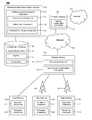
- FIG. 1is a block diagram of a system according to an embodiment of the disclosure.
- FIG. 2is a flow chart illustrating a method according to an embodiment of the disclosure.
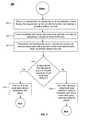
- FIG. 3is a flow chart illustrating another method according to an embodiment of the disclosure.
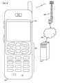
- FIG. 4is an illustration of a mobile device according to an embodiment of the disclosure.
- FIG. 5is a block diagram of a mobile device according to an embodiment of the disclosure.
- FIG. 6is a block diagram of a software configuration for a mobile device according to an embodiment of the disclosure.
- FIG. 7is an illustration of a general purpose computer system suitable for implementing the several embodiments of the disclosure.
- DHCPdynamic firewall and dynamic host control protocol
- VLANsvirtual local area networks
- the dynamic character of the virtual local area networks' provisioningalleviates the need for maintaining and managing static combinations of subnet interface and virtual local area network tags. This may result in reduced network overhead and network management expense as virtual local area networks may be created and dismantled on demand. Flexibility may be an additional benefit as virtual local area networks may be created with provisioning information drawn randomly from resource pools maintained on a server. When a dynamically provisioned virtual local area network is dismantled, the provisioning information used to create it is returned to its resource pools for future use.
- the systemembodies a server that draws provisioning information from resource pools and sends the information to an access device and a firewall device to establish the virtual local area network.
- Physical interfaces on each devicesupport and may be associated with a limited quantity of the subnet interfaces.
- the association of a subnet interface and a virtual local area network tag with a physical interface on each deviceenables the establishment of the virtual local area network. This action may allow the virtual local area network to be joined by a client device that has requested access to network services.
- the process of virtual local area network provisioningmay be initiated by a client device requesting access to services on a network.
- the servermay determine that a policy currently in effect requires that the client device be associated with a virtual local area before being granted access to the requested services.
- a virtual local area networkmay be provisioned by the server to handle traffic associated with the client device's accessing of the requested network services.
- the servermay draw upon separate pools of configuration resources necessary to provision the virtual local area network determined to be required by the server when authenticating the client device.
- the poolscomprise virtual local area network names or tags, subnet interface configuration information, and policies related to client devices, users, groups, and/or resources.
- One or more policiesmay require a client device to be associated with a virtual local area network.
- the serverrandomly draws virtual local area network or tags and subnet information from their respective pools and sends this information along with the policy and physical interface designation to the access and firewall devices for association with the physical port designated on each device.
- the association of the new subnet interface, tag, and policy with the physical interface or port on each deviceestablishes the virtual local area network.
- the serverat approximately the same time associates the client device with the virtual local area network.
- the client devicemay then begin accessing the desired network services.
- a client devicemay be unaware that a virtual local area network is being provisioned and established on behalf of the client device to provide it access to the network services it is requesting. For some users, groups, client devices, and/or network services or combination thereof, association with a virtual local area network may not be necessary at all. Access to network services is usually the client device's primary objective and any association with a virtual local area network enforced by the server to provide this access may not be apparent or of interest to the client device.
- the serverreviews policies associated with users, groups, client devices, and network services associated with the request received from the client device. The server makes a determination whether association with a virtual local area network will be necessary to grant the requested access and if the association will be to a dynamically created virtual local area network as described above or to a specific virtual local area network designated for a particular purpose.
- a client device upon authenticationwill be associated with a dynamically created and newly established and exclusive virtual local area network for that client device's sole use. That exclusive virtual local area network may then be terminated and dismantled when the client device ends its session.
- specific virtual local area networks designated for particular purposesin some cases, specific subnet interface information and virtual local area network tags may be reserved for certain groups of client devices that must always be joined together using the same virtual local area network tag. Client devices that are members of these groups may have credentials or be associated with policies that are recognized by the server and provided the subnet interface information and virtual local area network tag associated with the group's virtual local area network.
- the serveralso has the functionality to recover subnet interface information and virtual local area network tags that were previously used in provisioning a virtual local area network but have become available as the client device associated with the virtual local area network has terminated its session. After a delay, the server returns the recovered subnet information and virtual local area network tags to their respective pools for future reuse.
- the system 100comprises an authentication/authorization application server 102 , an authentication/authorization application 110 , a configuration database 120 , an access device 130 , a firewall device 140 , a first client device 150 , a wireless base station 180 , a network 190 , and an Internet 192 .
- Embodiments of the system 100typically comprise an indefinite number of additional client devices 160 and 170 .
- Embodiments of the systemalso typically comprise additional wireless base stations 182 . Interactions of the first client device 150 and the additional client devices 160 and 170 either singly or collectively may be represented henceforth as the client device 150 .
- the authentication/authorization server 102may be any general purpose computer system, as discussed in greater detail hereinafter.
- the authentication/authorization server 102may comprise one computer or a plurality of computers, for example a server farm wherein many server computers cooperate to share a processing load.
- the authentication/authorization server 102may comprise a plurality of computers that are located at different places, for example to provide geographical diversity and increased service reliability.
- the authentication/authorization server 102executes one or more applications that provide services to at least one of the client devices 150 including hosting of the authentication/authorization application 110 .
- the authentication/authorization application 110executes on the authentication/authorization server 102 and receives messages from the access device 130 containing requests from the client device 150 for authentication and access to network services.
- the authentication/authorization application 110comprises a communication component 112 that communicates with the access device 130 , the firewall device 140 , and other devices as needed.
- the communication component 112receives authentication requests from the access device 130 generated by the client device 150 accessing network services.
- the communication component 130also sends configuration information and associated instructions to the access device 130 and the firewall device 140 when a virtual local area network is to be provisioned.
- the communication component 112also engages in other communication with the access device 130 and the firewall device 140 about the maintenance and tear down of the virtual local area network and the recovery of virtual local area network tags and subnet interface configuration information after tear down.
- the authentication/authorization application 110also comprises the authenticator component 114 that authenticates client devices 150 seeking to access network services.
- the authenticator component 114receives the request for authentication from the access device 130 on behalf of the client device 150 .
- the authenticator component 114examines the authentication request and determines if a policy is currently in place for the client device 150 , a user or group associated with the client device 150 , the network services requested, a combination thereof, or any other aspect of the request. If such a policy is in place, the authenticator component 114 reviews the policy and makes a determination whether the policy requires that the client device 150 should be associated with a virtual local area network.
- the authenticator component 114may then complete the steps of port-based authentication as described in standard 802.1x issued by the Institute of Electrical and Electronics Engineers (IEEE). Port-based authentication may be a necessary step toward associating the client device 150 with a virtual local area network. After the authenticator component 114 completes port-based authentication of the client device 150 , if necessary, and any other steps required to authenticate the client device 150 for access to services, it may contact the communication component 112 with the request to generate configuration information in accordance with the policy found and provision the virtual local area network for the client device 150 .
- IEEEInstitute of Electrical and Electronics Engineers
- the authentication/authorization application 110also comprises the resource pool access component 116 that performs interaction with the configuration database 120 to obtain configuration and policies information to provision virtual local area networks and take delivery of recovered configuration information after virtual local area networks have been torn down.
- the resource pool access component 116is called upon by the authenticator component 114 to locate applicable policies when the client device 150 is seeking to be authenticated.
- the resource pool access component 116is also called upon by the configuration component 112 after the client device 150 has been authenticated to draw subnet interface information and virtual local area network tag information from the configuration database 120 for the purpose of provisioning the virtual local area network needed to provide the client device 150 access to the requested network services.
- the authentication/authorization application 110may alternatively be referred to as the dynamic network interfaces application.
- the configuration database 120is associated with the authentication/authorization server 102 and is the repository of configuration and other information provided to the access device 130 and the firewall device 140 to configure interfaces and enable the provisioning of virtual local area networks.
- the configuration database 120comprises the subnet interface pool 122 that holds the information needed to configure the subnet interfaces on the access device 130 and the firewall device 140 to provision the virtual local area network for the client device 150 .
- Information associated with configuring a subnet interfacecomprises an internet protocol address, an internet protocol subnet mask, an internet protocol default gateway, a domain name system (DNS) server, and a dynamic host control protocol (DHCP) server.
- DNSdomain name system
- DHCPdynamic host control protocol
- the subnet interface pool 122may comprise sub-pools that each contain a quantity of the specific individual elements or combinations of the individual elements described above that together allow subnet interfaces to be configured on the access device 130 and the firewall device 140 .
- the configuration database 120also comprises the tag pool 124 that is a collection of names, numbers, or other designations provided to virtual local area networks when they are provisioned. Virtual local area network tags may alternatively be referred to as 802.1Q tags.
- the numbering system and sequence of selection of tags from the tag pool 124may be subject to guidelines defined by the authentication/authorization application 110 . Alternatively, the assignment of numbers or names to tags may be random. Individual tags may be set aside and reserved or preconfigured for use by groups with reserved subnet interface information.
- the configuration database 120also comprises a policies pool 126 .
- Policiesare guidelines associated with client devices 150 , users, groups, and/or available network services. As accessing services may involve contacting resources outside of an enterprise network and hence call for accessing network ports on a firewall device 140 , policies also may be associated with the firewall device 140 . Policies may outline the types of traffic allowed in and out of a network.
- the authenticator component 114in developing a response to a request from the client device 150 for access to network services, may be required to adhere to a policy found in the policies pool 126 associated with the firewall device 140 in addition to any policies found that regard the client device 150 , users, and/or groups.
- the authentication/authorization application 110may be bound by a policy regarding some aspect of a request originated by the client device 150 or a more general directive applying to some or all virtual local area network configurations.
- the access device 130receives the initial request to access network services from the client device 150 and furnishes the request to the authenticator component 114 of the authentication/authorization application 110 for authentication.
- the access device 130comprises the messaging component 132 that handles communication between the access device 130 and the other components of the system 100 including the client device 150 and the authentication/authorization server 102 .
- the messaging component 132receives the request from the client device 150 and sends its message to the authentication/authorization application 110 requesting the authenticator component 114 to authenticate the client device 150 .
- the messaging component 132also receives the reply from the authentication/authorization server 102 containing the information needed to configure the necessary subnet interface.
- the messaging component 132has the functionality to read, process, and reply to messages sent by the authentication/authorization server 102 and the client device 150 .
- the access device 130also comprises the access device configuration component 134 that uses the configuration information received from the authentication/authorization server 102 to configure the necessary interface on the access device 130 .
- the access device configuration component 134receives the internet protocol address, subnet mask, and other information needed to configure the new subnet interface on the access device 130 , configures the subnet interface, and associates the subnet interface with the virtual local area network tag and physical interface designation also received from the authentication/authorization server 102 .
- the access device configuration component 134also contains functionality to understand and carry out instructions received in the transmission from the authentication/authorization server 102 that accompany the requested configuration information. The instructions may call for the interface to be configured in accordance with a policy drawn by the resource pool access component 116 from the policies pool 126 when the authentication/authorization application 110 was fulfilling the request received from the access device 130 .
- the access device 130may notify the authentication/authorization application 110 .
- the authentication/authorization application 110controls the process of virtual local area network teardown which may include directing the access device 130 and the firewall device 140 to shut down the subnet interfaces dedicated to the virtual local area network being terminated.
- the authentication/authorization application 110also releases the internet protocol configuration information used to configure the subnet interface and the associated virtual local area network tag.
- the released subnet configuration information and virtual local area network tag after a short delayare returned to their respective pools in the configuration database 120 and are made available for future reuse.
- the access device 130may be a single physical device or more than one physical device that have similar functionality and perform substantially the same tasks in connection with the system 100 .
- the access device 130may be an Ethernet switch, WiFi access point, edge switch, other wireless access point, or other device with the capability to control physical access to a network based on the authentication status of the client device 150 .
- the system 100may comprise more than one access device 130 .
- the firewall device 140provides connection to the internet 192 for devices on the network 190 through a secure network port or ports on the firewall device 140 .
- the firewall device 140may be a dedicated physical device or functionality resident on another device that inspects and regulates traffic flowing through its ports.
- the firewall device 140may comprise at least one of a router, a network gateway device, other device, or combination of these devices.
- the firewall device 140is the component of the system 100 through which the client device 150 using a virtual local area network makes contact with resources on the Internet 192 .
- a subnet interfaceis configured and associated with a physical interface on the firewall device 140 to provision the virtual local area network per the request of the client device 150 .
- the firewall device 140also may concurrently provide access to the Internet 192 to other devices on the network 190 unrelated to the client device 150 and unrelated to security levels and network traffic in connection with a virtual local area network provisioned for the client device 150 .
- the firewall device 140also may concurrently provide access to the Internet 192 to devices that are not components of the system 100 .
- the firewall device 140has functionality to segregate network traffic intended for the client device 150 on a virtual local area network from other traffic originating from the Internet 192 or elsewhere.
- the firewall device 140comprises the firewall configuration component 142 that receives configuration information from the authentication/authorization server 102 .
- the firewall device 140configures a subnet interface using the configuration information and associates the subnet interface with a physical interface on the firewall device 140 to enable the provisioning of a virtual local area network. Similar to the access device 130 , the firewall device 140 configures a subnet interface using the subnet interface information, virtual local area network tag, and policy received from the authentication/authorization server 102 and associates the subnet interface with a physical interface on the firewall device 140 .
- the firewall configuration component 142receives the configuration information from the authentication/authorization server 102 as a result of the authentication/authorization server 102 authenticating a request from the client device 150 for access to network services.
- the subnet interface information receivedcomprises the internet protocol address, subnet mask, and other information needed to configure the subnet interface on the firewall device 140 dedicated to the virtual local area network.
- the firewall configuration component 142configures the subnet interface and associates the subnet interface with the virtual local area network tag, policy, and physical port designation also received from the authentication/authorization server 102 .
- the firewall configuration component 142contains functionality to receive, read, understand, and carry out instructions from the authentication/authorization server 102 in connection with configuration information sent by the authentication/authorization server 102 to configure a subnet interface and associate it with a physical interface on the firewall device 140 .
- the instructionsmay be in connection with a policy associated with the particular client device 150 involved with the newly provisioned virtual local area network or a level of security required for the virtual local area network.
- the instructionsmay also be in connection with a group or community of interest of which the client device 150 is a member.
- the subnet interface information and virtual local area network tagare dedicated to the client device 150 and group.
- the client device 150is the component that seeks to access network services and contacts the access device 130 to begin the process.
- the client device 150may be one of a mobile telephone, personal digital assistant (PDA), laptop computer, tablet computer, desktop computer, set-top box, Voice over Internet Protocol (VoIP) desk set, printer, data appliance, camera, webcam, femtocell, and video device enabled to use the Internet Protocol (IP).
- PDApersonal digital assistant
- VoIPVoice over Internet Protocol
- the client device 150may be any device capable of using the Ethernet networking technology.
- the client devices 150 , 160 , 170comprise a supplicant component 152 , 162 , 172 that makes initial contact with the access device 130 to initiate the process of authentication toward being granted access to network services.
- the client device 150 , 160 , 170also comprises a messaging component 154 , 164 , 174 that conducts messaging with the other components of the system 100 after the client device 150 , 160 , 170 has been authenticated by the authentication/authorization application 110 .
- the wireless base stations 180 and 182may be any of a mobile telephone wireless base station, for example a Code Division Multiple Access (CDMA), Global System for Mobile Communications (GSM), and/or Universal Mobile Communications System (UMTS) mobile telephone wireless base station; a World-wide Interoperable Microwave Access (WiMAX) base station; a WiFi access point; or other wireless access device.
- CDMACode Division Multiple Access
- GSMGlobal System for Mobile Communications
- UMTSUniversal Mobile Communications System
- WiMAXWorld-wide Interoperable Microwave Access
- WiFi access pointor other wireless access device.
- the network 190promotes communication between the components of the system 100 .
- the network 190may be any communication network including a public data network (PDN), a public switched telephone network (PSTN), a private network, and/or a combination thereof.
- PDNpublic data network
- PSTNpublic switched telephone network
- private networka private network, and/or a combination thereof.
- the Internet 192is a worldwide, publicly accessible series of interconnected computer networks that transmit data by packet switching using the standard internet protocol (IP).
- IPinternet protocol
- the Internet 192may be any network external to the network 190 to which the client device 150 wishes to connect its virtual local area network.
- the authenticator component 114 of the authentication/authorization application 110receives a request from the messaging component 132 of the access device 130 .
- the messagecontains a request to authenticate the client device 150 that is seeking access to network services.
- the request from the access device 130 to the authentication/authorization application 110 for authentication of the client device 150may constitute all or a portion of the information contained in the request from the client device 150 to the access device 130 passed through in its original format.
- the authenticator component 114directs the resource pool access component 116 to access policies from the policies pool 126 connected to the request originated by the client device 150 .
- the authenticator component 114seeks to determine if one or more policies are currently in place regarding the client device 150 , a user or group associated with the client device 150 , the services requested, any combination thereof, or any other aspect of the request received from the client device 150 that might require the client device 150 to be associated with a virtual local area network before the client device 150 may be granted access to the requested network services.
- the authenticator component 114determines that a policy does in fact require that the client device 150 be associated with a virtual local area network to provide it access to the requested network services.
- the resource pool access component 116 of the authentication/authorization application 110obtains subnet interface information and a virtual local area network tag from the subnet interface pool 122 and the tag pool 124 , respectively. This information, along with the policy and a physical interface designation, is to be sent to the access device 130 and the firewall device 140 for each device to configure subnet interfaces and associate the subnet interfaces with the physical interfaces on each device.
- subnet interface information drawn from the subnet interface pool 122 and the virtual local area network tag drawn from the tag pool 124may be combined randomly and in the embodiment there may be benefit to the system 100 in doing so.
- Dynamically generating and randomly combining subnet interface identifications and virtual local area network tagsreduces some of the risks associated with virtual local area network identifications being permanently established and well known to many or all devices across a network.
- the communication component 112 of the authentication/authorization application 110creates messages for the access device 130 and the firewall device 140 containing the subnet interface information, virtual local area network tag, policy, and the physical port to be used by those devices in configuring the needed virtual local area network.
- the messagesalso may contain specific instructions to the access device 130 and the firewall device 140 to configure the subnet interfaces on the devices to provision the virtual local area network.
- the instructionsmay be related to the policy found in the policies pool 126 related to the client device 150 or network services requested by the client device 150 .
- the messagesmay be sent using the messaging framework of the dynamic host configuration protocol (DHCP), simple network management protocol (SNMP), or other protocol.
- DHCPdynamic host configuration protocol
- SNMPsimple network management protocol
- the authentication/authorization application 110sends the messages to the access device 130 and the firewall device 140 with the instructions to configure their interfaces with the subnet interface information and the accompanying virtual local area network tag and physical port designation.
- the access device configuration component 134 on the access device 130 and the firewall configuration component 142 on the firewall device 140take delivery of the information contained in the messages, configure subnet interfaces pursuant to instructions received, and associate the interfaces with the virtual local area network tag and physical interface on each device also specified in the message.
- the subnet interfacesare provisioned on the access device 130 and the firewall device 140 .
- the authentication/authorization application 110receives messages from the access device 130 and the firewall device 140 indicating that interfaces have been configured on each device and associated with the virtual local area network tag and physical interface specified in the message.
- the authentication/authorization application 110activates the virtual local area network and may send messaging that the services requested by the client device 150 may be accessed.
- the subnet interfaces on the access device 130 and the firewall device 140are deleted and the subnet information and virtual local area network tag associated with the virtual local area network are no longer in use.
- the access device configuration component 134provides notice to the communication component 112 of the authentication/authorization application 110 that the client device 150 has terminated its connection.
- the authentication/authorization application 110provides instructions to the access device 130 and firewall device 140 to terminate their subnet interfaces associated with the terminated virtual local area network.
- the resource pool access component 116may then restore the released subnet interface information and virtual local area network tag to their respective pools for later reuse.
- the subnet interface information and virtual local area network tagare not released immediately upon the client device 150 , 160 , 170 dropping its network connection.
- the subnet interface information and virtual local area network tagare placed in a temporary holding account for a brief period, for example one minute, in the event the client device 150 returns and is able to resume using the virtual local area network. Should the period of temporary holding expire and the client device 150 does not return, the subnet interface information and virtual local area network tag are placed in a second holding account for a longer period, for example for about an hour or several hours, wherein that information cannot be used for security reasons. At the expiry of the longer period, the subnet interface information and virtual local area network tag are finally returned their respective pools for reuse.
- a client device 150may be a member of a group or community of interest wherein members require access to the same network services.
- Providing members of a group access to one or more network services that do not often changemay be accomplished by creating a policy that associates each member of the group with the same virtual local area network tag each time one or more members of the group requests those specific network services.
- members of a disaster recovery team or emergency preparedness task forcemay desire to be placed in the same group regardless of where they are and how they approach the access device 130 .
- Dynamically drawing subnet interface information and randomly combining the information with a dynamically drawn virtual local area network tag as in other embodimentsis effective so long as each client device 150 identified as a member of a certain group is provided the same virtual local area network tag, associated subnet interface designation on the access device 130 and the firewall device, and physical port designation as every other client device 150 identified as a member of that group when they seek to access the network services specific to the group. Associating all members of a group with the same tag allows all of them to be joined together and provided the same network services each time.
- the authentication/authorization application 110receives a request from the access device 130 to on behalf of a client device 150 to authenticate the client device 150 and provide it access to specific network services.
- the authentication/authorization application 110 in authenticating the client device 150examines credentials or other identifying or qualifying information provided by the client device 150 and any policies associated with the client device 150 and or network services requested.
- the authentication/authorization application 110determines that the client device 150 is a member of a group wherein all members of the group who attempt to access one or more specific network services are to be assigned the same virtual local area network tag, subnet interface configuration, and physical port designation on the access device 130 and firewall device 140 .
- the authentication/authorization application 110determines if the client device 150 seeking access to the specific network services is the first member of the group to seek access. If the client device 150 is the first member of the group to seek access, the authentication/authorization application 110 at block 310 a draws subnet configuration information and a virtual local area network tag from its resource pools and furnishes the information along with the policy and physical interface information to the access device 130 and firewall device 140 for their configuring of interfaces and provisioning of the virtual local area network for the client device 150 .
- the provisioning informationmay be sent using the messaging framework of the dynamic host configuration protocol (DHCP), simple network management protocol (SNMP), or other protocol. Should client devices 160 and 170 that are also members of the group later seek to access the same network services while the client device 150 is still engaged in its session, they will be assigned the same virtual local area network tag as the client device 150 and joined into the active session with the client device 150 .
- DHCPdynamic host configuration protocol
- SNMPsimple network management protocol
- the authentication/authorization application 110 at block 308determines that the client device 150 is not the first member of the group to request access to the specific network services, this means that a virtual local area network specifically tagged for members of the group is currently in effect and one or more other client devices 160 , 170 is currently connected and accessing the specific network services.
- the authentication/authorization application 110 at block 310 bjoins the newly authenticated client device 150 to the virtual local area network currently tagged and in effect for the group.
- the client device 150may then begin interaction with other members of the group previously joined to the virtual local area network.
- client devices 150 , 160 , 170may join the same virtual local area network but be using different access devices 130 and firewall devices 140 .
- the authentication/authorization application 110 in joining these client devices 150 , 160 , 170 to the virtual local area networkmay need to provision subnet interfaces on the additional access devices 130 and firewall devices 140 to enable these client devices 150 , 160 , 170 to be joined.
- the last member of the groupdrops its connection to the virtual local area network, the specifically tagged virtual local area network for that group is terminated by the authentication/authorization application 110 .
- a specific virtual local area networkmay be permanently reserved for members of a group and that specific tag will remain reserved and designated for the group even when no members of the group are in a session and accessing the specific network services.
- a specific virtual local area network tagis not permanently reserved for members of the group.
- functionality within the authentication/authorization application 110causes it to randomly draw a virtual local area network tag from the policies pool 126 when the first client device 150 that is a member of the group authenticates and assign all subsequent authenticating client devices 160 , 170 that are members of the group the same virtual local area network tag.
- the virtual local area network with its specific tag for that sessionremains in effect until the last member of the group drops its connection whereupon the tag and subnet interface information are shortly returned to their respective pools for reuse as previously described.
- client devices 150 , 160 , 170 that are members of a groupmay reach the access device 130 from a variety of network types including one of a code division multiple access evolution-data optimized (CDMA EV-DO), code division multiple access round-trip time (CDMS RTT), Institute of Electrical and Electronics Engineers 802.1Q, Worldwide Interoperability for Microwave Access (WiMAX), digital subscriber line (DSL), and global system for mobile communications high-speed downlink packet access network (GSM HSDPA).
- CDMA EV-DOcode division multiple access evolution-data optimized
- CDMS RTTcode division multiple access round-trip time
- WiMAXWorldwide Interoperability for Microwave Access
- DSLdigital subscriber line
- GSM HSDPAglobal system for mobile communications high-speed downlink packet access network
- FIG. 4shows a wireless communications system including the handset 104 .
- FIG. 4depicts the handset 104 , which is operable for implementing aspects of the present disclosure, but the present disclosure should not be limited to these implementations.
- the handset 104may take various forms including a wireless handset, a pager, a personal digital assistant (PDA), a portable computer, a tablet computer, or a laptop computer. Many suitable handsets combine some or all of these functions.
- the handset 104is not a general purpose computing device like a portable, laptop or tablet computer, but rather is a special-purpose communications device such as a mobile phone, wireless handset, pager, or PDA.
- the handset 104may support specialized activities such as gaming, inventory control, job control, and/or task management functions, and so on.
- the handset 104includes a display 402 and a touch-sensitive surface or keys 404 for input by a user.
- the handset 104may present options for the user to select, controls for the user to actuate, and/or cursors or other indicators for the user to direct.
- the handset 104may further accept data entry from the user, including numbers to dial or various parameter values for configuring the operation of the handset.
- the handset 104may further execute one or more software or firmware applications in response to user commands. These applications may configure the handset 104 to perform various customized functions in response to user interaction. Additionally, the handset 104 may be programmed and/or configured over-the-air, for example from a wireless base station, a wireless access point, or a peer handset 104 .
- the handset 104may execute a web browser application which enables the display 402 to show a web page.
- the web pagemay be obtained via wireless communications with a cell tower 406 , a wireless network access node, a peer handset 104 or any other wireless communication network or system.
- the cell tower 406(or wireless network access node) is coupled to a wired network 408 , such as the Internet.
- the handset 104Via the wireless link and the wired network, the handset 104 has access to information on various servers, such as a server 410 .
- the server 410may provide content that may be shown on the display 402 .
- the handset 104may access the cell tower 406 through a peer handset 104 acting as an intermediary, in a relay type or hop type of connection.
- FIG. 5shows a block diagram of the handset 104 . While a variety of known components of handsets 102 are depicted, in an embodiment a subset of the listed components and/or additional components not listed may be included in the handset 104 .
- the handset 104includes a digital signal processor (DSP) 502 and a memory 504 .
- DSPdigital signal processor
- the handset 104may further include an antenna and front end unit 506 , a radio frequency (RF) transceiver 508 , an analog baseband processing unit 510 , a microphone 512 , an earpiece speaker 514 , a headset port 516 , an input/output interface 518 , a removable memory card 520 , a universal serial bus (USB) port 522 , an infrared port 524 , a vibrator 526 , a keypad 528 , a touch screen liquid crystal display (LCD) with a touch sensitive surface 530 , a touch screen/LCD controller 532 , a charge-coupled device (CCD) camera 534 , a camera controller 536 , and a global positioning system (GPS) sensor 538 .
- the handset 104may include another kind of display that does not provide a touch sensitive screen.
- the DSP 502may communicate directly with the memory 504 without passing through the input/output interface 518 .
- the DSP 502or some other form of controller or central processing unit operates to control the various components of the handset 104 in accordance with embedded software or firmware stored in memory 504 or stored in memory contained within the DSP 502 itself.
- the DSP 502may execute other applications stored in the memory 504 or made available via information carrier media such as portable data storage media like the removable memory card 520 or via wired or wireless network communications.
- the application softwaremay comprise a compiled set of machine-readable instructions that configure the DSP 502 to provide the desired functionality, or the application software may be high-level software instructions to be processed by an interpreter or compiler to indirectly configure the DSP 502 .
- the antenna and front end unit 506may be provided to convert between wireless signals and electrical signals, enabling the handset 104 to send and receive information from a cellular network or some other available wireless communications network or from a peer handset 104 .
- the antenna and front end unit 506may include multiple antennas to support beam forming and/or multiple input multiple output (MIMO) operations.
- MIMO operationsmay provide spatial diversity which can be used to overcome difficult channel conditions and/or increase channel throughput.
- the antenna and front end unit 506may include antenna tuning and/or impedance matching components, RF power amplifiers, and/or low noise amplifiers.
- the RF transceiver 508provides frequency shifting, converting received RF signals to baseband and converting baseband transmit signals to RF.
- a radio transceiver or RF transceivermay be understood to include other signal processing functionality such as modulation/demodulation, coding/decoding, interleaving/deinterleaving, spreading/despreading, inverse fast Fourier transforming (IFFT)/fast Fourier transforming (FFT), cyclic prefix appending/removal, and other signal processing functions.
- IFFTinverse fast Fourier transforming
- FFTfast Fourier transforming
- cyclic prefix appending/removaland other signal processing functions.
- the description hereseparates the description of this signal processing from the RF and/or radio stage and conceptually allocates that signal processing to the analog baseband processing unit 510 and/or the DSP 502 or other central processing unit.
- the analog baseband processing unit 510may provide various analog processing of inputs and outputs, for example analog processing of inputs from the microphone 512 and the headset port 516 and outputs to the earpiece speaker 514 and the headset port 516 .
- the analog baseband processing unit 510may have ports for connecting to the built-in microphone 512 and the earpiece speaker 514 that enable the handset 104 to be used as a cell phone.
- the analog baseband processing unit 510may further include a port for connecting to a headset or other hands-free microphone and speaker configuration.
- the analog baseband processing unit 510may provide digital-to-analog conversion in one signal direction and analog-to-digital conversion in the opposing signal direction.
- at least some of the functionality of the analog baseband processing unit 510may be provided by digital processing components, for example by the DSP 502 or by other central processing units.
- the DSP 502may perform modulation/demodulation, coding/decoding, interleaving/deinterleaving, spreading/despreading, inverse fast Fourier transforming (IFFT)/fast Fourier transforming (FFT), cyclic prefix appending/removal, and other signal processing functions associated with wireless communications.
- IFFTinverse fast Fourier transforming
- FFTfast Fourier transforming
- cyclic prefix appending/removalcyclic prefix appending/removal
- other signal processing functions associated with wireless communicationsfor example in a code division multiple access technology application, for a transmitter function the DSP 502 may perform modulation, coding, interleaving, and spreading, and for a receiver function the DSP 502 may perform despreading, deinterleaving, decoding, and demodulation.
- the DSP 502may perform modulation, coding, interleaving, inverse fast Fourier transforming, and cyclic prefix appending, and for a receiver function the DSP 502 may perform cyclic prefix removal, fast Fourier transforming, deinterleaving, decoding, and demodulation.
- OFDMAorthogonal frequency division multiplex access
- the DSP 502may communicate with a wireless network via the analog baseband processing unit 510 .
- the communicationmay provide Internet connectivity, enabling a user to gain access to content on the Internet and to send and receive e-mail or text messages.
- the input/output interface 518interconnects the DSP 502 and various memories and interfaces.
- the memory 504 and the removable memory card 520may provide software and data to configure the operation of the DSP 502 .
- the interfacesmay be the USB port 522 and the infrared port 524 .
- the USB port 522may enable the handset 104 to function as a peripheral device to exchange information with a personal computer or other computer system.
- the infrared port 524 and other optional portssuch as a Bluetooth interface or an IEEE 802.11 compliant wireless interface may enable the handset 104 to communicate wirelessly with other nearby handsets and/or wireless base stations.
- the input/output interface 518may further connect the DSP 502 to the vibrator 526 that, when triggered, causes the handset 104 to vibrate.
- the vibrator 526may serve as a mechanism for silently alerting the user to any of various events such as an incoming call, a new text message, and an appointment reminder.
- the keypad 528couples to the DSP 502 via the interface 518 to provide one mechanism for the user to make selections, enter information, and otherwise provide input to the handset 104 .
- Another input mechanismmay be the touch screen LCD 530 , which may also display text and/or graphics to the user.
- the touch screen LCD controller 532couples the DSP 502 to the touch screen LCD 530 .
- the CCD camera 534enables the handset 104 to take digital pictures.
- the DSP 502communicates with the CCD camera 534 via the camera controller 536 .
- the GPS sensor 538is coupled to the DSP 502 to decode global positioning system signals, thereby enabling the handset 104 to determine its position.
- a camera operating according to a technology other than charge coupled device camerasmay be employed.
- Various other peripheralsmay also be included to provide additional functions, e.g., radio and television reception.
- FIG. 6illustrates a software environment 602 that may be implemented by the DSP 502 .
- the DSP 502executes operating system drivers 604 that provide a platform from which the rest of the software operates.
- the operating system drivers 604provide drivers for the handset hardware with standardized interfaces that are accessible to application software.
- the operating system drivers 604include application management services (“AMS”) 606 that transfer control between applications running on the handset 104 .
- AMSapplication management services
- FIG. 6are also shown in FIG. 6 a web browser application 608 , a media player application 610 , and JAVA applets 612 .
- the web browser application 608configures the handset 104 to operate as a web browser, allowing a user to enter information into forms and select links to retrieve and view web pages.
- the media player application 610configures the handset 104 to retrieve and play audio or audiovisual media.
- the JAVA applets 612configure the handset 104 to provide games, utilities, and other functionality.
- the messaging component 614corresponds to the messaging component 154 , 164 , 174 described in the system 100 .
- FIG. 7illustrates a typical, general-purpose computer system suitable for implementing one or more embodiments disclosed herein.
- the computer system 380includes a processor 382 (which may be referred to as a central processor unit or CPU) that is in communication with memory devices including secondary storage 384 , read only memory (ROM) 386 , random access memory (RAM) 388 , input/output (I/O) devices 390 , and network connectivity devices 392 .
- the processormay be implemented as one or more CPU chips.
- the secondary storage 384is typically comprised of one or more disk drives or tape drives and is used for non-volatile storage of data and as an over-flow data storage device if RAM 388 is not large enough to hold all working data. Secondary storage 384 may be used to store programs which are loaded into RAM 388 when such programs are selected for execution.
- the ROM 386is used to store instructions and perhaps data which are read during program execution. ROM 386 is a non-volatile memory device which typically has a small memory capacity relative to the larger memory capacity of secondary storage.
- the RAM 388is used to store volatile data and perhaps to store instructions. Access to both ROM 386 and RAM 388 is typically faster than to secondary storage 384 .
- I/O devices 390may include printers, video monitors, liquid crystal displays (LCDs), touch screen displays, keyboards, keypads, switches, dials, mice, track balls, voice recognizers, card readers, paper tape readers, or other well-known input devices.
- LCDsliquid crystal displays
- touch screen displayskeyboards, keypads, switches, dials, mice, track balls, voice recognizers, card readers, paper tape readers, or other well-known input devices.
- the network connectivity devices 392may take the form of modems, modem banks, Ethernet cards, universal serial bus (USB) interface cards, serial interfaces, token ring cards, fiber distributed data interface (FDDI) cards, wireless local area network (WLAN) cards, radio transceiver cards such as code division multiple access (CDMA), global system for mobile communications (GSM), and/or worldwide interoperability for microwave access (WiMAX) radio transceiver cards, and other well-known network devices.
- These network connectivity devices 392may enable the processor 382 to communicate with an Internet or one or more intranets. With such a network connection, it is contemplated that the processor 382 might receive information from the network, or might output information to the network in the course of performing the above-described method steps. Such information, which is often represented as a sequence of instructions to be executed using processor 382 , may be received from and outputted to the network, for example, in the form of a computer data signal embodied in a carrier wave.
- Such informationmay be received from and outputted to the network, for example, in the form of a computer data baseband signal or signal embodied in a carrier wave.
- the baseband signal or signal embodied in the carrier wave generated by the network connectivity devices 392may propagate in or on the surface of electrical conductors, in coaxial cables, in waveguides, in optical media, for example optical fiber, or in the air or free space.
- the information contained in the baseband signal or signal embedded in the carrier wavemay be ordered according to different sequences, as may be desirable for either processing or generating the information or transmitting or receiving the information.
- the baseband signal or signal embedded in the carrier wave, or other types of signals currently used or hereafter developed, referred to herein as the transmission mediummay be generated according to several methods well known to one skilled in the art.
- the processor 382executes instructions, codes, computer programs, scripts which it accesses from hard disk, floppy disk, optical disk (these various disk based systems may all be considered secondary storage 384 ), ROM 386 , RAM 388 , or the network connectivity devices 392 . While only one processor 392 is shown, multiple processors may be present. Thus, while instructions may be discussed as executed by a processor, the instructions may be executed simultaneously, serially, or otherwise executed by one or multiple processors.
Landscapes
- Engineering & Computer Science (AREA)
- Computer Networks & Wireless Communication (AREA)
- Signal Processing (AREA)
- Computer Security & Cryptography (AREA)
- Computer Hardware Design (AREA)
- Computing Systems (AREA)
- General Engineering & Computer Science (AREA)
- Data Exchanges In Wide-Area Networks (AREA)
- Computer And Data Communications (AREA)
Abstract
Description
Claims (19)
Priority Applications (1)
| Application Number | Priority Date | Filing Date | Title |
|---|---|---|---|
| US13/612,830US8752160B1 (en) | 2008-11-13 | 2012-09-13 | Dynamic firewall and dynamic host configuration protocol configuration |
Applications Claiming Priority (2)
| Application Number | Priority Date | Filing Date | Title |
|---|---|---|---|
| US12/270,537US8363658B1 (en) | 2008-11-13 | 2008-11-13 | Dynamic firewall and dynamic host configuration protocol configuration |
| US13/612,830US8752160B1 (en) | 2008-11-13 | 2012-09-13 | Dynamic firewall and dynamic host configuration protocol configuration |
Related Parent Applications (1)
| Application Number | Title | Priority Date | Filing Date |
|---|---|---|---|
| US12/270,537ContinuationUS8363658B1 (en) | 2008-11-13 | 2008-11-13 | Dynamic firewall and dynamic host configuration protocol configuration |
Publications (1)
| Publication Number | Publication Date |
|---|---|
| US8752160B1true US8752160B1 (en) | 2014-06-10 |
Family
ID=47562316
Family Applications (2)
| Application Number | Title | Priority Date | Filing Date |
|---|---|---|---|
| US12/270,537Active2031-06-05US8363658B1 (en) | 2008-11-13 | 2008-11-13 | Dynamic firewall and dynamic host configuration protocol configuration |
| US13/612,830ActiveUS8752160B1 (en) | 2008-11-13 | 2012-09-13 | Dynamic firewall and dynamic host configuration protocol configuration |
Family Applications Before (1)
| Application Number | Title | Priority Date | Filing Date |
|---|---|---|---|
| US12/270,537Active2031-06-05US8363658B1 (en) | 2008-11-13 | 2008-11-13 | Dynamic firewall and dynamic host configuration protocol configuration |
Country Status (1)
| Country | Link |
|---|---|
| US (2) | US8363658B1 (en) |
Cited By (8)
| Publication number | Priority date | Publication date | Assignee | Title |
|---|---|---|---|---|
| US9396016B1 (en) | 2015-05-27 | 2016-07-19 | Sprint Communications Company L.P. | Handoff of virtual machines based on security requirements |
| US9608759B2 (en) | 2015-05-21 | 2017-03-28 | Sprint Communications Company L.P. | Optical communication system with hardware root of trust (HRoT) and network function virtualization (NFV) |
| US9743282B2 (en) | 2015-01-20 | 2017-08-22 | Sprint Communications Company L.P. | Computer system hardware validation for virtual communication network elements |
| US9979562B2 (en) | 2015-05-27 | 2018-05-22 | Sprint Communications Company L.P. | Network function virtualization requirements to service a long term evolution (LTE) network |
| US10042662B1 (en) | 2015-04-07 | 2018-08-07 | Sprint Communications Company L.P. | Network function virtualization (NFV) parameter trust in data communication systems |
| US20200177447A1 (en)* | 2018-11-29 | 2020-06-04 | Cisco Technology, Inc. | Systems and Methods for Enterprise Fabric Creation |
| US11218384B2 (en)* | 2015-06-02 | 2022-01-04 | Alcatel Lucent | Method of creating and deleting vWLAN dynamically in a fixed access network sharing environment |
| US20220231967A1 (en)* | 2015-04-03 | 2022-07-21 | Nicira, Inc. | Provisioning network services in a software defined data center |
Families Citing this family (74)
| Publication number | Priority date | Publication date | Assignee | Title |
|---|---|---|---|---|
| US8924469B2 (en) | 2008-06-05 | 2014-12-30 | Headwater Partners I Llc | Enterprise access control and accounting allocation for access networks |
| US8725123B2 (en) | 2008-06-05 | 2014-05-13 | Headwater Partners I Llc | Communications device with secure data path processing agents |
| US8250207B2 (en) | 2009-01-28 | 2012-08-21 | Headwater Partners I, Llc | Network based ambient services |
| US8391834B2 (en) | 2009-01-28 | 2013-03-05 | Headwater Partners I Llc | Security techniques for device assisted services |
| US8275830B2 (en) | 2009-01-28 | 2012-09-25 | Headwater Partners I Llc | Device assisted CDR creation, aggregation, mediation and billing |
| US8406748B2 (en) | 2009-01-28 | 2013-03-26 | Headwater Partners I Llc | Adaptive ambient services |
| US8832777B2 (en) | 2009-03-02 | 2014-09-09 | Headwater Partners I Llc | Adapting network policies based on device service processor configuration |
| US8898293B2 (en) | 2009-01-28 | 2014-11-25 | Headwater Partners I Llc | Service offer set publishing to device agent with on-device service selection |
| US8626115B2 (en) | 2009-01-28 | 2014-01-07 | Headwater Partners I Llc | Wireless network service interfaces |
| US8548428B2 (en) | 2009-01-28 | 2013-10-01 | Headwater Partners I Llc | Device group partitions and settlement platform |
| US8402111B2 (en) | 2009-01-28 | 2013-03-19 | Headwater Partners I, Llc | Device assisted services install |
| US8340634B2 (en) | 2009-01-28 | 2012-12-25 | Headwater Partners I, Llc | Enhanced roaming services and converged carrier networks with device assisted services and a proxy |
| US8924543B2 (en) | 2009-01-28 | 2014-12-30 | Headwater Partners I Llc | Service design center for device assisted services |
| US8589541B2 (en) | 2009-01-28 | 2013-11-19 | Headwater Partners I Llc | Device-assisted services for protecting network capacity |
| US8346225B2 (en) | 2009-01-28 | 2013-01-01 | Headwater Partners I, Llc | Quality of service for device assisted services |
| US8635335B2 (en) | 2009-01-28 | 2014-01-21 | Headwater Partners I Llc | System and method for wireless network offloading |
| US8363658B1 (en) | 2008-11-13 | 2013-01-29 | Sprint Communications Company L.P. | Dynamic firewall and dynamic host configuration protocol configuration |
| US8745191B2 (en) | 2009-01-28 | 2014-06-03 | Headwater Partners I Llc | System and method for providing user notifications |
| US9572019B2 (en) | 2009-01-28 | 2017-02-14 | Headwater Partners LLC | Service selection set published to device agent with on-device service selection |
| US9351193B2 (en) | 2009-01-28 | 2016-05-24 | Headwater Partners I Llc | Intermediate networking devices |
| US9706061B2 (en) | 2009-01-28 | 2017-07-11 | Headwater Partners I Llc | Service design center for device assisted services |
| US10492102B2 (en) | 2009-01-28 | 2019-11-26 | Headwater Research Llc | Intermediate networking devices |
| US10484858B2 (en) | 2009-01-28 | 2019-11-19 | Headwater Research Llc | Enhanced roaming services and converged carrier networks with device assisted services and a proxy |
| US9955332B2 (en) | 2009-01-28 | 2018-04-24 | Headwater Research Llc | Method for child wireless device activation to subscriber account of a master wireless device |
| US9578182B2 (en) | 2009-01-28 | 2017-02-21 | Headwater Partners I Llc | Mobile device and service management |
| US9755842B2 (en) | 2009-01-28 | 2017-09-05 | Headwater Research Llc | Managing service user discovery and service launch object placement on a device |
| US10326800B2 (en) | 2009-01-28 | 2019-06-18 | Headwater Research Llc | Wireless network service interfaces |
| US10779177B2 (en) | 2009-01-28 | 2020-09-15 | Headwater Research Llc | Device group partitions and settlement platform |
| US12166596B2 (en) | 2009-01-28 | 2024-12-10 | Disney Enterprises, Inc. | Device-assisted services for protecting network capacity |
| US10057775B2 (en) | 2009-01-28 | 2018-08-21 | Headwater Research Llc | Virtualized policy and charging system |
| US9253663B2 (en) | 2009-01-28 | 2016-02-02 | Headwater Partners I Llc | Controlling mobile device communications on a roaming network based on device state |
| US8793758B2 (en) | 2009-01-28 | 2014-07-29 | Headwater Partners I Llc | Security, fraud detection, and fraud mitigation in device-assisted services systems |
| US10248996B2 (en) | 2009-01-28 | 2019-04-02 | Headwater Research Llc | Method for operating a wireless end-user device mobile payment agent |
| US11973804B2 (en) | 2009-01-28 | 2024-04-30 | Headwater Research Llc | Network service plan design |
| US9392462B2 (en) | 2009-01-28 | 2016-07-12 | Headwater Partners I Llc | Mobile end-user device with agent limiting wireless data communication for specified background applications based on a stored policy |
| US10798252B2 (en) | 2009-01-28 | 2020-10-06 | Headwater Research Llc | System and method for providing user notifications |
| US10841839B2 (en) | 2009-01-28 | 2020-11-17 | Headwater Research Llc | Security, fraud detection, and fraud mitigation in device-assisted services systems |
| US10264138B2 (en) | 2009-01-28 | 2019-04-16 | Headwater Research Llc | Mobile device and service management |
| US9954975B2 (en) | 2009-01-28 | 2018-04-24 | Headwater Research Llc | Enhanced curfew and protection associated with a device group |
| US10715342B2 (en) | 2009-01-28 | 2020-07-14 | Headwater Research Llc | Managing service user discovery and service launch object placement on a device |
| US10783581B2 (en) | 2009-01-28 | 2020-09-22 | Headwater Research Llc | Wireless end-user device providing ambient or sponsored services |
| US10064055B2 (en) | 2009-01-28 | 2018-08-28 | Headwater Research Llc | Security, fraud detection, and fraud mitigation in device-assisted services systems |
| US9980146B2 (en) | 2009-01-28 | 2018-05-22 | Headwater Research Llc | Communications device with secure data path processing agents |
| US8893009B2 (en)* | 2009-01-28 | 2014-11-18 | Headwater Partners I Llc | End user device that secures an association of application to service policy with an application certificate check |
| US9647918B2 (en) | 2009-01-28 | 2017-05-09 | Headwater Research Llc | Mobile device and method attributing media services network usage to requesting application |
| US10200541B2 (en) | 2009-01-28 | 2019-02-05 | Headwater Research Llc | Wireless end-user device with divided user space/kernel space traffic policy system |
| US9571559B2 (en) | 2009-01-28 | 2017-02-14 | Headwater Partners I Llc | Enhanced curfew and protection associated with a device group |
| US9565707B2 (en) | 2009-01-28 | 2017-02-07 | Headwater Partners I Llc | Wireless end-user device with wireless data attribution to multiple personas |
| US12389218B2 (en) | 2009-01-28 | 2025-08-12 | Headwater Research Llc | Service selection set publishing to device agent with on-device service selection |
| US8606911B2 (en) | 2009-03-02 | 2013-12-10 | Headwater Partners I Llc | Flow tagging for service policy implementation |
| US9858559B2 (en) | 2009-01-28 | 2018-01-02 | Headwater Research Llc | Network service plan design |
| US10237757B2 (en) | 2009-01-28 | 2019-03-19 | Headwater Research Llc | System and method for wireless network offloading |
| US9609510B2 (en) | 2009-01-28 | 2017-03-28 | Headwater Research Llc | Automated credential porting for mobile devices |
| US11218854B2 (en) | 2009-01-28 | 2022-01-04 | Headwater Research Llc | Service plan design, user interfaces, application programming interfaces, and device management |
| US12432130B2 (en) | 2009-01-28 | 2025-09-30 | Headwater Research Llc | Flow tagging for service policy implementation |
| US11985155B2 (en) | 2009-01-28 | 2024-05-14 | Headwater Research Llc | Communications device with secure data path processing agents |
| US9557889B2 (en) | 2009-01-28 | 2017-01-31 | Headwater Partners I Llc | Service plan design, user interfaces, application programming interfaces, and device management |
| US12388810B2 (en) | 2009-01-28 | 2025-08-12 | Headwater Research Llc | End user device that secures an association of application to service policy with an application certificate check |
| US9270559B2 (en) | 2009-01-28 | 2016-02-23 | Headwater Partners I Llc | Service policy implementation for an end-user device having a control application or a proxy agent for routing an application traffic flow |
| ES2667397T3 (en)* | 2009-11-02 | 2018-05-10 | Assia Spe, Llc | Device Abstraction Proxy |
| US8639801B2 (en)* | 2010-03-12 | 2014-01-28 | Softlayer Technologies, Inc. | Real-time automated virtual private network (VPN) access management |
| US9154826B2 (en) | 2011-04-06 | 2015-10-06 | Headwater Partners Ii Llc | Distributing content and service launch objects to mobile devices |
| US8699962B2 (en)* | 2011-12-15 | 2014-04-15 | Proximetry, Inc. | Systems and methods for preparing a telecommunication network for providing services |
| US20140156820A1 (en)* | 2012-11-30 | 2014-06-05 | Hewlett-Packard Development Company, L.P. | Configuration information selection based on extracted information |
| US9560524B1 (en) | 2013-12-03 | 2017-01-31 | Sprint Communications Company L.P. | Wireless network application access by a wireless communication device via an untrusted access node |
| CN104092691A (en)* | 2014-07-15 | 2014-10-08 | 北京奇虎科技有限公司 | Implementation method and client of networked firewall without root authority |
| US9712489B2 (en)* | 2014-07-29 | 2017-07-18 | Aruba Networks, Inc. | Client device address assignment following authentication |
| US9875344B1 (en) | 2014-09-05 | 2018-01-23 | Silver Peak Systems, Inc. | Dynamic monitoring and authorization of an optimization device |
| US10491567B2 (en)* | 2017-03-17 | 2019-11-26 | Verizon Patent And Licensing Inc. | Dynamic firewall configuration based on proxy container deployment |
| US10868836B1 (en)* | 2017-06-07 | 2020-12-15 | Amazon Technologies, Inc. | Dynamic security policy management |
| WO2020221454A1 (en)* | 2019-05-02 | 2020-11-05 | Huawei Technologies Co., Ltd. | Network device and method for policy based access to a wireless network |
| CN112653608B (en)* | 2020-12-14 | 2023-01-20 | 聚好看科技股份有限公司 | Display device, mobile terminal and cross-network data transmission method |
| CN115622808B (en)* | 2022-12-13 | 2023-05-23 | 北京市大数据中心 | Method for secure isolation, electronic device, computer readable medium |
| US12386923B1 (en)* | 2023-05-24 | 2025-08-12 | Amazon Technologies, Inc. | Managed activation of licensed software for resources in peered networks |
Citations (61)
| Publication number | Priority date | Publication date | Assignee | Title |
|---|---|---|---|---|
| US5959990A (en) | 1996-03-12 | 1999-09-28 | Bay Networks, Inc. | VLAN frame format |
| US6088801A (en) | 1997-01-10 | 2000-07-11 | Grecsek; Matthew T. | Managing the risk of executing a software process using a capabilities assessment and a policy |
| US6304901B1 (en) | 1996-01-02 | 2001-10-16 | Cisco Technology, Inc. | Multiple VLAN architecture system |
| US20020009078A1 (en)* | 2000-05-12 | 2002-01-24 | Tim Wilson | Server and method for providing specific network services |
| US20020112052A1 (en) | 2001-02-13 | 2002-08-15 | Peter Brittingham | Remote computer capabilities querying and certification |
| US6539388B1 (en) | 1997-10-22 | 2003-03-25 | Kabushika Kaisha Toshiba | Object-oriented data storage and retrieval system using index table |
| US20030084165A1 (en) | 2001-10-12 | 2003-05-01 | Openwave Systems Inc. | User-centric session management for client-server interaction using multiple applications and devices |
| US20030217148A1 (en) | 2002-05-16 | 2003-11-20 | Mullen Glen H. | Method and apparatus for LAN authentication on switch |
| US20040185876A1 (en)* | 2003-03-07 | 2004-09-23 | Computer Associates Think, Inc. | Mobility management in wireless networks |
| US20040218538A1 (en) | 1999-10-22 | 2004-11-04 | Dell Usa L.P. | Site-to-site dynamic virtual local area network |
| US20050165953A1 (en) | 2004-01-22 | 2005-07-28 | Yoshihiro Oba | Serving network selection and multihoming using IP access network |
| US20050210241A1 (en) | 2004-03-22 | 2005-09-22 | Samsung Electronics Co., Ltd. | Method and apparatus for digital rights management using certificate revocation list |
| US20060047835A1 (en)* | 2004-07-02 | 2006-03-02 | Greaux Jeffrey E | Method and System for LAN and WLAN access to e-commerce sites via Client Server Proxy |
| US20060126611A1 (en)* | 2004-11-23 | 2006-06-15 | Microsoft Corporation | System and method for a distributed server for peer-to-peer networks |
| US20060168648A1 (en) | 2005-01-26 | 2006-07-27 | Lockdown Networks, Inc. | Enabling dynamic authentication with different protocols on the same port for a switch |
| US20060206933A1 (en) | 2005-03-10 | 2006-09-14 | Stsn General Holdings Inc. | Security for mobile devices in a wireless network |
| US20060212549A1 (en) | 2005-03-17 | 2006-09-21 | Fujitsu Limited | IP address assigning method, VLAN changing device, VLAN changing system and quarantine process system |
| US20060250979A1 (en)* | 2005-03-30 | 2006-11-09 | Bernd Gauweiler | Simple installation of devices on a network |
| US20060259624A1 (en)* | 2005-04-08 | 2006-11-16 | Benq Corporation | Network address transition methods and systems |
| US20060268749A1 (en) | 2005-05-31 | 2006-11-30 | Rahman Shahriar I | Multiple wireless spanning tree protocol for use in a wireless mesh network |
| US20060274774A1 (en) | 2005-06-07 | 2006-12-07 | Extreme Networks, Inc. | Methods, systems, and computer program products for dynamic network access device port and user device configuration for implementing device-based and user-based policies |
| US20060274744A1 (en) | 2005-06-07 | 2006-12-07 | Minoru Nagai | Dynamic VLAN ID assignment and packet transfer apparatus |
| US20070250833A1 (en) | 2006-04-14 | 2007-10-25 | Microsoft Corporation | Managing virtual machines with system-wide policies |
| US20070266432A1 (en) | 2006-05-10 | 2007-11-15 | Fujitsu Limited | Packet routing method, computer system, and computer product |
| US7370346B2 (en) | 2003-04-29 | 2008-05-06 | Hewlett-Packard Development Company, L.P. | Method and apparatus for access security services |
| US20080172492A1 (en) | 2007-01-11 | 2008-07-17 | Mandayam Thondanur Raghunath | System and method for virtualized resource configuration |
| US20080198858A1 (en)* | 2007-02-19 | 2008-08-21 | William Mark Townsley | Simple Virtual Private Network For Small Local Area Networks |
| US20080270606A1 (en) | 2007-04-30 | 2008-10-30 | Mark Gooch | Remote client remediation |
| US20080285557A1 (en)* | 2007-05-18 | 2008-11-20 | Huawei Technologies Co., Ltd. | Method, System and Relay Device for Transmitting Packet |
| US20080304457A1 (en)* | 2007-06-08 | 2008-12-11 | Pascal Thubert | Secure mobile IPv6 registration |
| US20080320585A1 (en) | 2007-05-25 | 2008-12-25 | Nirwan Ansari | METHOD AND SYSTEM TO MITIGATE LOW RATE DENIAL OF SERVICE (DoS) ATTACKS |
| US20090006585A1 (en) | 2005-12-30 | 2009-01-01 | Ling Chen | Ip Address Allocation Method |
| US7523484B2 (en) | 2003-09-24 | 2009-04-21 | Infoexpress, Inc. | Systems and methods of controlling network access |
| US7551619B2 (en) | 2005-10-13 | 2009-06-23 | Trapeze Networks, Inc. | Identity-based networking |
| US20090178119A1 (en) | 2008-01-07 | 2009-07-09 | Commscope, Inc. Of North Carolina | Methods, systems and computer program products for provisioning vlan services in a network |
| US20090199285A1 (en) | 2008-01-26 | 2009-08-06 | Puneet Agarwal | Systems and Methods for For Proxying Cookies for SSL VPN Clientless Sessions |
| US20090219834A1 (en) | 2004-06-30 | 2009-09-03 | Qualcomm Incorporated | Dynamic Configuration of IP for a Terminal Equipment Attached to a Wireless Device |
| US7606232B1 (en)* | 2005-11-09 | 2009-10-20 | Juniper Networks, Inc. | Dynamic virtual local area network (VLAN) interface configuration |
| US20090268737A1 (en) | 2008-04-24 | 2009-10-29 | James Ryan Giles | Method and Apparatus for VLAN-Based Selective Path Routing |
| US20090304007A1 (en) | 2004-02-18 | 2009-12-10 | Woven Systems, Inc. | Mechanism for determining a congestion metric for a path in a network |
| US20100071024A1 (en) | 2008-09-12 | 2010-03-18 | Juniper Networks, Inc. | Hierarchical application of security services within a computer network |
| US7684438B2 (en) | 2001-08-10 | 2010-03-23 | Strix Systems, Inc. | Virtual linking using a wireless device |
| US20100080238A1 (en) | 2008-09-30 | 2010-04-01 | Nortel Networks Limited | Extended Private LAN |
| US7698394B2 (en) | 2003-12-23 | 2010-04-13 | Alcatel Lucent | Global network management configuration |
| US7720031B1 (en) | 2004-10-15 | 2010-05-18 | Cisco Technology, Inc. | Methods and devices to support mobility of a client across VLANs and subnets, while preserving the client's assigned IP address |
| US7735114B2 (en) | 2003-09-04 | 2010-06-08 | Foundry Networks, Inc. | Multiple tiered network security system, method and apparatus using dynamic user policy assignment |
| US20100238813A1 (en)* | 2006-06-29 | 2010-09-23 | Nortel Networks Limited | Q-in-Q Ethernet rings |
| US7822982B2 (en) | 2005-06-16 | 2010-10-26 | Hewlett-Packard Development Company, L.P. | Method and apparatus for automatic and secure distribution of a symmetric key security credential in a utility computing environment |
| US20110004913A1 (en)* | 2007-07-31 | 2011-01-06 | Symbol Technologies, Inc. | Architecture for seamless enforcement of security policies when roaming across ip subnets in ieee 802.11 wireless networks |
| US7898982B2 (en) | 2006-03-22 | 2011-03-01 | Alcatel Lucent | Logical group endpoint discovery for data communication network |
| US20110103259A1 (en) | 2009-11-04 | 2011-05-05 | Gunes Aybay | Methods and apparatus for configuring a virtual network switch |
| US8000266B2 (en)* | 2006-12-19 | 2011-08-16 | Cisco Technology, Inc. | Shared virtual device ports |
| US8032942B2 (en) | 2007-12-31 | 2011-10-04 | Intel Corporation | Configuration of virtual trusted platform module |
| US8059641B1 (en)* | 2006-07-20 | 2011-11-15 | Avaya Inc. | Encapsulation method discovery protocol for network address translation gateway traversal |
| US20120131573A1 (en) | 2010-11-18 | 2012-05-24 | Rajashekar Dasari | Methods, systems, and apparatus to prioritize computing devices for virtualization |
| US8189600B2 (en) | 2006-04-10 | 2012-05-29 | Cisco Technology, Inc. | Method for IP routing when using dynamic VLANs with web based authentication |
| US20120134291A1 (en) | 2009-01-28 | 2012-05-31 | Headwater Partners I, Llc | Network Based Service Profile Management with User Preference, Adaptive Policy, Network Neutrality, and User Privacy |
| US8245270B2 (en) | 2005-09-01 | 2012-08-14 | Microsoft Corporation | Resource based dynamic security authorization |
| US8341717B1 (en) | 2008-11-13 | 2012-12-25 | Sprint Communications Company L.P. | Dynamic network policies based on device classification |
| US8363658B1 (en) | 2008-11-13 | 2013-01-29 | Sprint Communications Company L.P. | Dynamic firewall and dynamic host configuration protocol configuration |
| US8479266B1 (en) | 2008-11-13 | 2013-07-02 | Sprint Communications Company L.P. | Network assignment appeal architecture and process |
- 2008
- 2008-11-13USUS12/270,537patent/US8363658B1/enactiveActive
- 2012
- 2012-09-13USUS13/612,830patent/US8752160B1/enactiveActive
Patent Citations (63)
| Publication number | Priority date | Publication date | Assignee | Title |
|---|---|---|---|---|
| US6304901B1 (en) | 1996-01-02 | 2001-10-16 | Cisco Technology, Inc. | Multiple VLAN architecture system |
| US5959990A (en) | 1996-03-12 | 1999-09-28 | Bay Networks, Inc. | VLAN frame format |
| US6088801A (en) | 1997-01-10 | 2000-07-11 | Grecsek; Matthew T. | Managing the risk of executing a software process using a capabilities assessment and a policy |
| US6539388B1 (en) | 1997-10-22 | 2003-03-25 | Kabushika Kaisha Toshiba | Object-oriented data storage and retrieval system using index table |
| US20040218538A1 (en) | 1999-10-22 | 2004-11-04 | Dell Usa L.P. | Site-to-site dynamic virtual local area network |
| US20020009078A1 (en)* | 2000-05-12 | 2002-01-24 | Tim Wilson | Server and method for providing specific network services |
| US20020112052A1 (en) | 2001-02-13 | 2002-08-15 | Peter Brittingham | Remote computer capabilities querying and certification |
| US7684438B2 (en) | 2001-08-10 | 2010-03-23 | Strix Systems, Inc. | Virtual linking using a wireless device |
| US20030084165A1 (en) | 2001-10-12 | 2003-05-01 | Openwave Systems Inc. | User-centric session management for client-server interaction using multiple applications and devices |
| US20030217148A1 (en) | 2002-05-16 | 2003-11-20 | Mullen Glen H. | Method and apparatus for LAN authentication on switch |
| US20040185876A1 (en)* | 2003-03-07 | 2004-09-23 | Computer Associates Think, Inc. | Mobility management in wireless networks |
| US20080229393A1 (en) | 2003-04-29 | 2008-09-18 | Congdon Paul T | Method and apparatus for access security services |
| US7370346B2 (en) | 2003-04-29 | 2008-05-06 | Hewlett-Packard Development Company, L.P. | Method and apparatus for access security services |
| US7735114B2 (en) | 2003-09-04 | 2010-06-08 | Foundry Networks, Inc. | Multiple tiered network security system, method and apparatus using dynamic user policy assignment |
| US7523484B2 (en) | 2003-09-24 | 2009-04-21 | Infoexpress, Inc. | Systems and methods of controlling network access |
| US7698394B2 (en) | 2003-12-23 | 2010-04-13 | Alcatel Lucent | Global network management configuration |
| US20050165953A1 (en) | 2004-01-22 | 2005-07-28 | Yoshihiro Oba | Serving network selection and multihoming using IP access network |
| US20090304007A1 (en) | 2004-02-18 | 2009-12-10 | Woven Systems, Inc. | Mechanism for determining a congestion metric for a path in a network |
| US20050210241A1 (en) | 2004-03-22 | 2005-09-22 | Samsung Electronics Co., Ltd. | Method and apparatus for digital rights management using certificate revocation list |
| US20090219834A1 (en) | 2004-06-30 | 2009-09-03 | Qualcomm Incorporated | Dynamic Configuration of IP for a Terminal Equipment Attached to a Wireless Device |
| US20060047835A1 (en)* | 2004-07-02 | 2006-03-02 | Greaux Jeffrey E | Method and System for LAN and WLAN access to e-commerce sites via Client Server Proxy |
| US7720031B1 (en) | 2004-10-15 | 2010-05-18 | Cisco Technology, Inc. | Methods and devices to support mobility of a client across VLANs and subnets, while preserving the client's assigned IP address |
| US20060126611A1 (en)* | 2004-11-23 | 2006-06-15 | Microsoft Corporation | System and method for a distributed server for peer-to-peer networks |
| US20060168648A1 (en) | 2005-01-26 | 2006-07-27 | Lockdown Networks, Inc. | Enabling dynamic authentication with different protocols on the same port for a switch |
| US20060206933A1 (en) | 2005-03-10 | 2006-09-14 | Stsn General Holdings Inc. | Security for mobile devices in a wireless network |
| US20060212549A1 (en) | 2005-03-17 | 2006-09-21 | Fujitsu Limited | IP address assigning method, VLAN changing device, VLAN changing system and quarantine process system |
| US20060250979A1 (en)* | 2005-03-30 | 2006-11-09 | Bernd Gauweiler | Simple installation of devices on a network |
| US20060259624A1 (en)* | 2005-04-08 | 2006-11-16 | Benq Corporation | Network address transition methods and systems |
| US20060268749A1 (en) | 2005-05-31 | 2006-11-30 | Rahman Shahriar I | Multiple wireless spanning tree protocol for use in a wireless mesh network |
| US20060274774A1 (en) | 2005-06-07 | 2006-12-07 | Extreme Networks, Inc. | Methods, systems, and computer program products for dynamic network access device port and user device configuration for implementing device-based and user-based policies |
| US20060274744A1 (en) | 2005-06-07 | 2006-12-07 | Minoru Nagai | Dynamic VLAN ID assignment and packet transfer apparatus |
| US7822982B2 (en) | 2005-06-16 | 2010-10-26 | Hewlett-Packard Development Company, L.P. | Method and apparatus for automatic and secure distribution of a symmetric key security credential in a utility computing environment |
| US8245270B2 (en) | 2005-09-01 | 2012-08-14 | Microsoft Corporation | Resource based dynamic security authorization |
| US7551619B2 (en) | 2005-10-13 | 2009-06-23 | Trapeze Networks, Inc. | Identity-based networking |
| US7983258B1 (en) | 2005-11-09 | 2011-07-19 | Juniper Networks, Inc. | Dynamic virtual local area network (VLAN) interface configuration |
| US7606232B1 (en)* | 2005-11-09 | 2009-10-20 | Juniper Networks, Inc. | Dynamic virtual local area network (VLAN) interface configuration |
| US20090006585A1 (en) | 2005-12-30 | 2009-01-01 | Ling Chen | Ip Address Allocation Method |
| US7898982B2 (en) | 2006-03-22 | 2011-03-01 | Alcatel Lucent | Logical group endpoint discovery for data communication network |
| US8189600B2 (en) | 2006-04-10 | 2012-05-29 | Cisco Technology, Inc. | Method for IP routing when using dynamic VLANs with web based authentication |
| US20070250833A1 (en) | 2006-04-14 | 2007-10-25 | Microsoft Corporation | Managing virtual machines with system-wide policies |
| US20070266432A1 (en) | 2006-05-10 | 2007-11-15 | Fujitsu Limited | Packet routing method, computer system, and computer product |
| US20100238813A1 (en)* | 2006-06-29 | 2010-09-23 | Nortel Networks Limited | Q-in-Q Ethernet rings |
| US8059641B1 (en)* | 2006-07-20 | 2011-11-15 | Avaya Inc. | Encapsulation method discovery protocol for network address translation gateway traversal |
| US8000266B2 (en)* | 2006-12-19 | 2011-08-16 | Cisco Technology, Inc. | Shared virtual device ports |
| US20080172492A1 (en) | 2007-01-11 | 2008-07-17 | Mandayam Thondanur Raghunath | System and method for virtualized resource configuration |
| US20080198858A1 (en)* | 2007-02-19 | 2008-08-21 | William Mark Townsley | Simple Virtual Private Network For Small Local Area Networks |
| US20080270606A1 (en) | 2007-04-30 | 2008-10-30 | Mark Gooch | Remote client remediation |
| US20080285557A1 (en)* | 2007-05-18 | 2008-11-20 | Huawei Technologies Co., Ltd. | Method, System and Relay Device for Transmitting Packet |
| US20080320585A1 (en) | 2007-05-25 | 2008-12-25 | Nirwan Ansari | METHOD AND SYSTEM TO MITIGATE LOW RATE DENIAL OF SERVICE (DoS) ATTACKS |
| US20080304457A1 (en)* | 2007-06-08 | 2008-12-11 | Pascal Thubert | Secure mobile IPv6 registration |
| US20110004913A1 (en)* | 2007-07-31 | 2011-01-06 | Symbol Technologies, Inc. | Architecture for seamless enforcement of security policies when roaming across ip subnets in ieee 802.11 wireless networks |
| US8032942B2 (en) | 2007-12-31 | 2011-10-04 | Intel Corporation | Configuration of virtual trusted platform module |
| US20090178119A1 (en) | 2008-01-07 | 2009-07-09 | Commscope, Inc. Of North Carolina | Methods, systems and computer program products for provisioning vlan services in a network |
| US20090199285A1 (en) | 2008-01-26 | 2009-08-06 | Puneet Agarwal | Systems and Methods for For Proxying Cookies for SSL VPN Clientless Sessions |
| US20090268737A1 (en) | 2008-04-24 | 2009-10-29 | James Ryan Giles | Method and Apparatus for VLAN-Based Selective Path Routing |
| US20100071024A1 (en) | 2008-09-12 | 2010-03-18 | Juniper Networks, Inc. | Hierarchical application of security services within a computer network |
| US20100080238A1 (en) | 2008-09-30 | 2010-04-01 | Nortel Networks Limited | Extended Private LAN |
| US8341717B1 (en) | 2008-11-13 | 2012-12-25 | Sprint Communications Company L.P. | Dynamic network policies based on device classification |
| US8363658B1 (en) | 2008-11-13 | 2013-01-29 | Sprint Communications Company L.P. | Dynamic firewall and dynamic host configuration protocol configuration |
| US8479266B1 (en) | 2008-11-13 | 2013-07-02 | Sprint Communications Company L.P. | Network assignment appeal architecture and process |
| US20120134291A1 (en) | 2009-01-28 | 2012-05-31 | Headwater Partners I, Llc | Network Based Service Profile Management with User Preference, Adaptive Policy, Network Neutrality, and User Privacy |
| US20110103259A1 (en) | 2009-11-04 | 2011-05-05 | Gunes Aybay | Methods and apparatus for configuring a virtual network switch |
| US20120131573A1 (en) | 2010-11-18 | 2012-05-24 | Rajashekar Dasari | Methods, systems, and apparatus to prioritize computing devices for virtualization |
Non-Patent Citations (12)
| Title |
|---|
| Advisory Action dated Oct. 24, 2012, U.S. Appl. No. 12/270,568, filed Nov. 13, 2008. |
| Delker, Jason R., et al., Patent Application entitled, "Dynamic Firewall and Dynamic Host Configuration Protocol Configuration," filed Nov. 13, 2008, U.S. Appl. No. 12/270,537. |
| Delker, Jason R., et al., Patent Application entitled, "Dynamic Network Policies Based on Device Classification," filed Nov. 13, 2008, U.S. Appl. No. 12/270,554. |
| Delker, Jason R., et al., Patent Application entitled, "Network Assignment Appeal Architecture and Process," filed Nov. 13, 2008, U.S. Appl. No. 12/270,568. |
| FAIPP Office Action dated Jun. 13, 2012, U.S. Appl. No. 12/270,568, filed Nov. 13, 2008. |
| Final Office Action dated Aug. 14, 2012, U.S. Appl. No. 12/270,568, filed Nov. 13, 2008. |
| Notice of Allowance dated Aug. 16, 2012, U.S. Appl. No. 12/270,554, filed Nov. 13, 2008. |
| Notice of Allowance dated Aug. 7, 2012, U.S. Appl. No. 12/270,537, filed Nov. 13, 2008. |
| Notice of Allowance dated Dec. 4, 2012, U.S. Appl. No. 12/270,568, filed Nov. 13, 2008. |
| Pre-Interview Communication dated Apr. 11, 2012, U.S. Appl. No. 12/270,537, filed Nov. 13, 2008. |
| Pre-Interview Communication dated Jun. 13, 2012, U.S. Appl. No. 12/270,554, filed Nov. 13, 2008. |
| Pre-Interview Communication dated May 1, 2012, U.S. Appl. No. 12/270,568, filed Nov. 13, 2008. |
Cited By (15)
| Publication number | Priority date | Publication date | Assignee | Title |
|---|---|---|---|---|
| US9743282B2 (en) | 2015-01-20 | 2017-08-22 | Sprint Communications Company L.P. | Computer system hardware validation for virtual communication network elements |
| US9906961B2 (en) | 2015-01-20 | 2018-02-27 | Sprint Communications Company L.P. | Computer system hardware validation for virtual communication network elements |
| US20220231967A1 (en)* | 2015-04-03 | 2022-07-21 | Nicira, Inc. | Provisioning network services in a software defined data center |
| US12301475B2 (en) | 2015-04-03 | 2025-05-13 | VMware LLC | Provisioning network services in a software defined data center |
| US11811680B2 (en)* | 2015-04-03 | 2023-11-07 | Nicira, Inc. | Provisioning network services in a software defined data center |
| US10042662B1 (en) | 2015-04-07 | 2018-08-07 | Sprint Communications Company L.P. | Network function virtualization (NFV) parameter trust in data communication systems |
| US10050739B2 (en) | 2015-05-21 | 2018-08-14 | Sprint Communications Company L.P. | Optical communication system with hardware root of trust (HRoT) and network function virtualization (NFV) |
| US9608759B2 (en) | 2015-05-21 | 2017-03-28 | Sprint Communications Company L.P. | Optical communication system with hardware root of trust (HRoT) and network function virtualization (NFV) |
| US9396016B1 (en) | 2015-05-27 | 2016-07-19 | Sprint Communications Company L.P. | Handoff of virtual machines based on security requirements |
| US10505762B2 (en) | 2015-05-27 | 2019-12-10 | Sprint Communications Company L.P. | Network function virtualization requirements to service a long term evolution (LTE) network |
| US10019281B2 (en) | 2015-05-27 | 2018-07-10 | Sprint Communications Company L.P. | Handoff of virtual machines based on security requirements |
| US9979562B2 (en) | 2015-05-27 | 2018-05-22 | Sprint Communications Company L.P. | Network function virtualization requirements to service a long term evolution (LTE) network |
| US11218384B2 (en)* | 2015-06-02 | 2022-01-04 | Alcatel Lucent | Method of creating and deleting vWLAN dynamically in a fixed access network sharing environment |
| US20200177447A1 (en)* | 2018-11-29 | 2020-06-04 | Cisco Technology, Inc. | Systems and Methods for Enterprise Fabric Creation |
| US11165636B2 (en)* | 2018-11-29 | 2021-11-02 | Cisco Technology, Inc. | Systems and methods for enterprise fabric creation |
Also Published As
| Publication number | Publication date |
|---|---|
| US8363658B1 (en) | 2013-01-29 |
Similar Documents
| Publication | Publication Date | Title |
|---|---|---|
| US8752160B1 (en) | Dynamic firewall and dynamic host configuration protocol configuration | |
| US8479266B1 (en) | Network assignment appeal architecture and process | |
| US8554934B1 (en) | Application single sign on leveraging virtual local area network identifier | |
| US8341717B1 (en) | Dynamic network policies based on device classification | |
| CN102362478B (en) | Method and device for providing shared services | |
| US9398010B1 (en) | Provisioning layer two network access for mobile devices | |
| RU2564251C2 (en) | Dynamic creation of account in protected network with wireless access point | |
| CN113115480A (en) | Address information sending method, address information obtaining method, address information sending device, address information obtaining device, address information equipment and address information medium | |
| US9065684B2 (en) | IP phone terminal, server, authenticating apparatus, communication system, communication method, and recording medium | |
| US12309121B2 (en) | Securing access to network devices utilizing authentication and dynamically generated temporary firewall rules | |
| CN112672336B (en) | Method, communication device and communication system for realizing external authentication | |
| EP4075867A1 (en) | Application instance determination method, device, and system | |
| US20140057598A1 (en) | Automatic access to network nodes | |
| WO2014206199A1 (en) | Account login method, equipment and system | |
| US12068879B2 (en) | Smart device provisioning | |
| US20250106639A1 (en) | Systems and methods for using a unique routing indicator to connect to a network | |
| WO2021239098A1 (en) | Service obtaining method and apparatus, and communication device and readable storage medium | |
| WO2014032518A1 (en) | Method and system for establishing l2tp tunnel | |
| JP7651722B2 (en) | COMMUNICATION METHOD AND COMMUNICATION DEVICE | |
| WO2023083174A1 (en) | Subscription update method and device, network element, and medium | |
| KR101258508B1 (en) | Common path accessing system based on terminal identification and method thereof | |
| US20100198950A1 (en) | Method to deliver services over existing wireless lan infrastructure | |
| WO2024119292A1 (en) | Network service method, communication apparatus, and communication system | |
| CN117858083A (en) | Method and device for authenticating equipment in personal networking and communication equipment | |
| KR100863209B1 (en) | Common Path Connection System and Method Using Terminal Identification |
Legal Events
| Date | Code | Title | Description |
|---|---|---|---|
| STCF | Information on status: patent grant | Free format text:PATENTED CASE | |
| AS | Assignment | Owner name:DEUTSCHE BANK TRUST COMPANY AMERICAS, NEW YORK Free format text:GRANT OF FIRST PRIORITY AND JUNIOR PRIORITY SECURITY INTEREST IN PATENT RIGHTS;ASSIGNOR:SPRINT COMMUNICATIONS COMPANY L.P.;REEL/FRAME:041895/0210 Effective date:20170203 | |
| MAFP | Maintenance fee payment | Free format text:PAYMENT OF MAINTENANCE FEE, 4TH YEAR, LARGE ENTITY (ORIGINAL EVENT CODE: M1551) Year of fee payment:4 | |
| AS | Assignment | Owner name:SPRINT COMMUNICATIONS COMPANY L.P., KANSAS Free format text:TERMINATION AND RELEASE OF FIRST PRIORITY AND JUNIOR PRIORITY SECURITY INTEREST IN PATENT RIGHTS;ASSIGNOR:DEUTSCHE BANK TRUST COMPANY AMERICAS;REEL/FRAME:052969/0475 Effective date:20200401 Owner name:DEUTSCHE BANK TRUST COMPANY AMERICAS, NEW YORK Free format text:SECURITY AGREEMENT;ASSIGNORS:T-MOBILE USA, INC.;ISBV LLC;T-MOBILE CENTRAL LLC;AND OTHERS;REEL/FRAME:053182/0001 Effective date:20200401 | |
| AS | Assignment | Owner name:T-MOBILE INNOVATIONS LLC, KANSAS Free format text:ASSIGNMENT OF ASSIGNORS INTEREST;ASSIGNOR:SPRINT COMMUNICATIONS COMPANY L.P.;REEL/FRAME:055604/0001 Effective date:20210303 | |
| MAFP | Maintenance fee payment | Free format text:PAYMENT OF MAINTENANCE FEE, 8TH YEAR, LARGE ENTITY (ORIGINAL EVENT CODE: M1552); ENTITY STATUS OF PATENT OWNER: LARGE ENTITY Year of fee payment:8 | |
| AS | Assignment | Owner name:SPRINT SPECTRUM LLC, KANSAS Free format text:RELEASE BY SECURED PARTY;ASSIGNOR:DEUTSCHE BANK TRUST COMPANY AMERICAS;REEL/FRAME:062595/0001 Effective date:20220822 Owner name:SPRINT INTERNATIONAL INCORPORATED, KANSAS Free format text:RELEASE BY SECURED PARTY;ASSIGNOR:DEUTSCHE BANK TRUST COMPANY AMERICAS;REEL/FRAME:062595/0001 Effective date:20220822 Owner name:SPRINT COMMUNICATIONS COMPANY L.P., KANSAS Free format text:RELEASE BY SECURED PARTY;ASSIGNOR:DEUTSCHE BANK TRUST COMPANY AMERICAS;REEL/FRAME:062595/0001 Effective date:20220822 Owner name:SPRINTCOM LLC, KANSAS Free format text:RELEASE BY SECURED PARTY;ASSIGNOR:DEUTSCHE BANK TRUST COMPANY AMERICAS;REEL/FRAME:062595/0001 Effective date:20220822 Owner name:CLEARWIRE IP HOLDINGS LLC, KANSAS Free format text:RELEASE BY SECURED PARTY;ASSIGNOR:DEUTSCHE BANK TRUST COMPANY AMERICAS;REEL/FRAME:062595/0001 Effective date:20220822 Owner name:CLEARWIRE COMMUNICATIONS LLC, KANSAS Free format text:RELEASE BY SECURED PARTY;ASSIGNOR:DEUTSCHE BANK TRUST COMPANY AMERICAS;REEL/FRAME:062595/0001 Effective date:20220822 Owner name:BOOST WORLDWIDE, LLC, KANSAS Free format text:RELEASE BY SECURED PARTY;ASSIGNOR:DEUTSCHE BANK TRUST COMPANY AMERICAS;REEL/FRAME:062595/0001 Effective date:20220822 Owner name:ASSURANCE WIRELESS USA, L.P., KANSAS Free format text:RELEASE BY SECURED PARTY;ASSIGNOR:DEUTSCHE BANK TRUST COMPANY AMERICAS;REEL/FRAME:062595/0001 Effective date:20220822 Owner name:T-MOBILE USA, INC., WASHINGTON Free format text:RELEASE BY SECURED PARTY;ASSIGNOR:DEUTSCHE BANK TRUST COMPANY AMERICAS;REEL/FRAME:062595/0001 Effective date:20220822 Owner name:T-MOBILE CENTRAL LLC, WASHINGTON Free format text:RELEASE BY SECURED PARTY;ASSIGNOR:DEUTSCHE BANK TRUST COMPANY AMERICAS;REEL/FRAME:062595/0001 Effective date:20220822 Owner name:PUSHSPRING, LLC, WASHINGTON Free format text:RELEASE BY SECURED PARTY;ASSIGNOR:DEUTSCHE BANK TRUST COMPANY AMERICAS;REEL/FRAME:062595/0001 Effective date:20220822 Owner name:LAYER3 TV, LLC, WASHINGTON Free format text:RELEASE BY SECURED PARTY;ASSIGNOR:DEUTSCHE BANK TRUST COMPANY AMERICAS;REEL/FRAME:062595/0001 Effective date:20220822 Owner name:IBSV LLC, WASHINGTON Free format text:RELEASE BY SECURED PARTY;ASSIGNOR:DEUTSCHE BANK TRUST COMPANY AMERICAS;REEL/FRAME:062595/0001 Effective date:20220822 |