US8752081B2 - Methods, systems and apparatus for multi-purpose metering - Google Patents
Methods, systems and apparatus for multi-purpose meteringDownload PDFInfo
- Publication number
- US8752081B2 US8752081B2US13/690,652US201213690652AUS8752081B2US 8752081 B2US8752081 B2US 8752081B2US 201213690652 AUS201213690652 AUS 201213690652AUS 8752081 B2US8752081 B2US 8752081B2
- Authority
- US
- United States
- Prior art keywords
- mppm
- base unit
- information
- data
- tag
- Prior art date
- Legal status (The legal status is an assumption and is not a legal conclusion. Google has not performed a legal analysis and makes no representation as to the accuracy of the status listed.)
- Active
Links
- 238000000034methodMethods0.000titleclaimsabstractdescription111
- 238000012546transferMethods0.000claimsabstractdescription28
- 238000012806monitoring deviceMethods0.000claimsabstractdescription13
- 230000006854communicationEffects0.000claimsdescription91
- 238000004891communicationMethods0.000claimsdescription85
- 238000012545processingMethods0.000claimsdescription68
- 230000004044responseEffects0.000claimsdescription32
- 238000003860storageMethods0.000claimsdescription15
- 238000007906compressionMethods0.000claimsdescription9
- 230000006835compressionEffects0.000claimsdescription9
- 238000013144data compressionMethods0.000claimsdescription5
- 230000003247decreasing effectEffects0.000claims3
- 101100206395Caenorhabditis elegans tag-250 geneProteins0.000description132
- 230000033001locomotionEffects0.000description73
- 230000015654memoryEffects0.000description68
- 238000012544monitoring processMethods0.000description68
- 230000008569processEffects0.000description50
- 238000010586diagramMethods0.000description41
- 230000005540biological transmissionEffects0.000description37
- 238000001514detection methodMethods0.000description28
- 230000003287optical effectEffects0.000description28
- 238000003032molecular dockingMethods0.000description27
- 230000006870functionEffects0.000description26
- 230000000875corresponding effectEffects0.000description24
- 238000005259measurementMethods0.000description24
- 230000000694effectsEffects0.000description16
- 238000004364calculation methodMethods0.000description11
- 230000000007visual effectEffects0.000description11
- 238000005516engineering processMethods0.000description10
- 230000005236sound signalEffects0.000description8
- 230000000737periodic effectEffects0.000description7
- 230000000717retained effectEffects0.000description7
- 230000006399behaviorEffects0.000description6
- 230000010267cellular communicationEffects0.000description6
- 239000011521glassSubstances0.000description6
- 238000004458analytical methodMethods0.000description5
- 238000012805post-processingMethods0.000description5
- 238000013480data collectionMethods0.000description4
- 230000007423decreaseEffects0.000description4
- 238000007726management methodMethods0.000description4
- 230000009467reductionEffects0.000description4
- 230000002829reductive effectEffects0.000description4
- 230000008901benefitEffects0.000description3
- 230000001413cellular effectEffects0.000description3
- 230000008859changeEffects0.000description3
- 230000001276controlling effectEffects0.000description2
- 238000010413gardeningMethods0.000description2
- 238000004519manufacturing processMethods0.000description2
- 230000006855networkingEffects0.000description2
- 230000002093peripheral effectEffects0.000description2
- 238000005070samplingMethods0.000description2
- 239000004065semiconductorSubstances0.000description2
- 230000001360synchronised effectEffects0.000description2
- IRLPACMLTUPBCL-KQYNXXCUSA-N5'-adenylyl sulfateChemical compoundC1=NC=2C(N)=NC=NC=2N1[C@@H]1O[C@H](COP(O)(=O)OS(O)(=O)=O)[C@@H](O)[C@H]1OIRLPACMLTUPBCL-KQYNXXCUSA-N0.000description1
- 238000004566IR spectroscopyMethods0.000description1
- -1Nickel Metal HydrideChemical class0.000description1
- 241000183290Scleropages leichardtiSpecies0.000description1
- 230000009471actionEffects0.000description1
- 230000002411adverseEffects0.000description1
- 238000013459approachMethods0.000description1
- OJIJEKBXJYRIBZ-UHFFFAOYSA-Ncadmium nickelChemical compound[Ni].[Cd]OJIJEKBXJYRIBZ-UHFFFAOYSA-N0.000description1
- JLQUFIHWVLZVTJ-UHFFFAOYSA-NcarbosulfanChemical compoundCCCCN(CCCC)SN(C)C(=O)OC1=CC=CC2=C1OC(C)(C)C2JLQUFIHWVLZVTJ-UHFFFAOYSA-N0.000description1
- 238000012512characterization methodMethods0.000description1
- ZPUCINDJVBIVPJ-LJISPDSOSA-NcocaineChemical compoundO([C@H]1C[C@@H]2CC[C@@H](N2C)[C@H]1C(=O)OC)C(=O)C1=CC=CC=C1ZPUCINDJVBIVPJ-LJISPDSOSA-N0.000description1
- 230000002596correlated effectEffects0.000description1
- 230000008878couplingEffects0.000description1
- 238000010168coupling processMethods0.000description1
- 238000005859coupling reactionMethods0.000description1
- 238000007405data analysisMethods0.000description1
- 238000013481data captureMethods0.000description1
- 238000013500data storageMethods0.000description1
- 230000006837decompressionEffects0.000description1
- 230000001934delayEffects0.000description1
- 230000000881depressing effectEffects0.000description1
- 238000013461designMethods0.000description1
- 238000009826distributionMethods0.000description1
- 230000005670electromagnetic radiationEffects0.000description1
- 230000007613environmental effectEffects0.000description1
- 238000000605extractionMethods0.000description1
- 238000001914filtrationMethods0.000description1
- 238000009472formulationMethods0.000description1
- 230000020169heat generationEffects0.000description1
- 230000000977initiatory effectEffects0.000description1
- 230000000670limiting effectEffects0.000description1
- 239000004973liquid crystal related substanceSubstances0.000description1
- 238000000691measurement methodMethods0.000description1
- 206010027175memory impairmentDiseases0.000description1
- QSHDDOUJBYECFT-UHFFFAOYSA-NmercuryChemical compound[Hg]QSHDDOUJBYECFT-UHFFFAOYSA-N0.000description1
- 229910052753mercuryInorganic materials0.000description1
- 229910052987metal hydrideInorganic materials0.000description1
- 229910044991metal oxideInorganic materials0.000description1
- 150000004706metal oxidesChemical class0.000description1
- 239000000203mixtureSubstances0.000description1
- 238000010295mobile communicationMethods0.000description1
- 238000012986modificationMethods0.000description1
- 230000004048modificationEffects0.000description1
- 229910052759nickelInorganic materials0.000description1
- PXHVJJICTQNCMI-UHFFFAOYSA-NnickelSubstances[Ni]PXHVJJICTQNCMI-UHFFFAOYSA-N0.000description1
- 229920001690polydopaminePolymers0.000description1
- 230000000644propagated effectEffects0.000description1
- 238000011160researchMethods0.000description1
- 230000003595spectral effectEffects0.000description1
- 230000003068static effectEffects0.000description1
- 230000002123temporal effectEffects0.000description1
- 238000012360testing methodMethods0.000description1
- 238000009482thermal adhesion granulationMethods0.000description1
- 230000009466transformationEffects0.000description1
- 238000012795verificationMethods0.000description1
- 230000002618waking effectEffects0.000description1
Images


Classifications
- H—ELECTRICITY
- H04—ELECTRIC COMMUNICATION TECHNIQUE
- H04W—WIRELESS COMMUNICATION NETWORKS
- H04W4/00—Services specially adapted for wireless communication networks; Facilities therefor
- H04W4/02—Services making use of location information
- H—ELECTRICITY
- H04—ELECTRIC COMMUNICATION TECHNIQUE
- H04L—TRANSMISSION OF DIGITAL INFORMATION, e.g. TELEGRAPHIC COMMUNICATION
- H04L12/00—Data switching networks
- H04L12/66—Arrangements for connecting between networks having differing types of switching systems, e.g. gateways
- H04L67/18—
- H04L67/22—
- H—ELECTRICITY
- H04—ELECTRIC COMMUNICATION TECHNIQUE
- H04L—TRANSMISSION OF DIGITAL INFORMATION, e.g. TELEGRAPHIC COMMUNICATION
- H04L67/00—Network arrangements or protocols for supporting network services or applications
- H04L67/50—Network services
- H04L67/52—Network services specially adapted for the location of the user terminal
- H—ELECTRICITY
- H04—ELECTRIC COMMUNICATION TECHNIQUE
- H04L—TRANSMISSION OF DIGITAL INFORMATION, e.g. TELEGRAPHIC COMMUNICATION
- H04L67/00—Network arrangements or protocols for supporting network services or applications
- H04L67/50—Network services
- H04L67/535—Tracking the activity of the user
- H—ELECTRICITY
- H04—ELECTRIC COMMUNICATION TECHNIQUE
- H04N—PICTORIAL COMMUNICATION, e.g. TELEVISION
- H04N21/00—Selective content distribution, e.g. interactive television or video on demand [VOD]
- H04N21/40—Client devices specifically adapted for the reception of or interaction with content, e.g. set-top-box [STB]; Operations thereof
- H04N21/41—Structure of client; Structure of client peripherals
- H04N21/4104—Peripherals receiving signals from specially adapted client devices
- H04N21/4126—The peripheral being portable, e.g. PDAs or mobile phones
- H04N21/41265—The peripheral being portable, e.g. PDAs or mobile phones having a remote control device for bidirectional communication between the remote control device and client device
- H—ELECTRICITY
- H04—ELECTRIC COMMUNICATION TECHNIQUE
- H04N—PICTORIAL COMMUNICATION, e.g. TELEVISION
- H04N21/00—Selective content distribution, e.g. interactive television or video on demand [VOD]
- H04N21/40—Client devices specifically adapted for the reception of or interaction with content, e.g. set-top-box [STB]; Operations thereof
- H04N21/43—Processing of content or additional data, e.g. demultiplexing additional data from a digital video stream; Elementary client operations, e.g. monitoring of home network or synchronising decoder's clock; Client middleware
- H04N21/439—Processing of audio elementary streams
- H04N21/4394—Processing of audio elementary streams involving operations for analysing the audio stream, e.g. detecting features or characteristics in audio streams
- H—ELECTRICITY
- H04—ELECTRIC COMMUNICATION TECHNIQUE
- H04N—PICTORIAL COMMUNICATION, e.g. TELEVISION
- H04N21/00—Selective content distribution, e.g. interactive television or video on demand [VOD]
- H04N21/40—Client devices specifically adapted for the reception of or interaction with content, e.g. set-top-box [STB]; Operations thereof
- H04N21/43—Processing of content or additional data, e.g. demultiplexing additional data from a digital video stream; Elementary client operations, e.g. monitoring of home network or synchronising decoder's clock; Client middleware
- H04N21/442—Monitoring of processes or resources, e.g. detecting the failure of a recording device, monitoring the downstream bandwidth, the number of times a movie has been viewed, the storage space available from the internal hard disk
- H04N21/44213—Monitoring of end-user related data
- H04N21/44218—Detecting physical presence or behaviour of the user, e.g. using sensors to detect if the user is leaving the room or changes his face expression during a TV program
- H—ELECTRICITY
- H04—ELECTRIC COMMUNICATION TECHNIQUE
- H04N—PICTORIAL COMMUNICATION, e.g. TELEVISION
- H04N21/00—Selective content distribution, e.g. interactive television or video on demand [VOD]
- H04N21/40—Client devices specifically adapted for the reception of or interaction with content, e.g. set-top-box [STB]; Operations thereof
- H04N21/43—Processing of content or additional data, e.g. demultiplexing additional data from a digital video stream; Elementary client operations, e.g. monitoring of home network or synchronising decoder's clock; Client middleware
- H04N21/443—OS processes, e.g. booting an STB, implementing a Java virtual machine in an STB or power management in an STB
- H04N21/4432—Powering on the client, e.g. bootstrap loading using setup parameters being stored locally or received from the server
- H—ELECTRICITY
- H04—ELECTRIC COMMUNICATION TECHNIQUE
- H04N—PICTORIAL COMMUNICATION, e.g. TELEVISION
- H04N21/00—Selective content distribution, e.g. interactive television or video on demand [VOD]
- H04N21/40—Client devices specifically adapted for the reception of or interaction with content, e.g. set-top-box [STB]; Operations thereof
- H04N21/43—Processing of content or additional data, e.g. demultiplexing additional data from a digital video stream; Elementary client operations, e.g. monitoring of home network or synchronising decoder's clock; Client middleware
- H04N21/443—OS processes, e.g. booting an STB, implementing a Java virtual machine in an STB or power management in an STB
- H04N21/4436—Power management, e.g. shutting down unused components of the receiver
- H—ELECTRICITY
- H04—ELECTRIC COMMUNICATION TECHNIQUE
- H04N—PICTORIAL COMMUNICATION, e.g. TELEVISION
- H04N21/00—Selective content distribution, e.g. interactive television or video on demand [VOD]
- H04N21/40—Client devices specifically adapted for the reception of or interaction with content, e.g. set-top-box [STB]; Operations thereof
- H04N21/45—Management operations performed by the client for facilitating the reception of or the interaction with the content or administrating data related to the end-user or to the client device itself, e.g. learning user preferences for recommending movies, resolving scheduling conflicts
- H04N21/4508—Management of client data or end-user data
- H04N21/4524—Management of client data or end-user data involving the geographical location of the client
- H—ELECTRICITY
- H04—ELECTRIC COMMUNICATION TECHNIQUE
- H04W—WIRELESS COMMUNICATION NETWORKS
- H04W4/00—Services specially adapted for wireless communication networks; Facilities therefor
- H04W4/02—Services making use of location information
- H04W4/029—Location-based management or tracking services
Definitions
- the present disclosurerelates generally to media monitoring and, more particularly, to methods, systems, and apparatus for multi-purpose metering.
- Consuming media presentationsgenerally involves listening to audio information and/or viewing video information.
- Media presentationsmay include, for example, radio programs, music, television programs, movies, still images, etc.
- Media-centric companiessuch as, for example, advertising companies, broadcast networks, etc. are often interested in the viewing and listening interests of audience to better market their products and/or to improve their programming.
- a well-known technique often used to measure the exposure and/or number of audience members exposed to mediainvolves awarding media exposure credit to a media presentation for each audience member that is exposed to the media presentation.
- PPMpersonal portable metering devices
- tagsalso known as portable metering devices, tags, and portable personal meters.
- a PPMis an electronic device that is typically worn (e.g., clipped to a belt or other apparel) or carried by an audience member and configured to monitor media consumption (e.g., viewing and/or listening activities) using any of a variety of media monitoring techniques.
- one technique of monitoring media consumptioninvolves detecting or collecting information (e.g., ancillary codes, signatures, etc.) from audio and/or video signals that are emitted or presented by media presentation devices (e.g., televisions, stereos, speakers, computers, video display devices, video games, mobile telephones, etc.).
- media presentation devicese.g., televisions, stereos, speakers, computers, video display devices, video games, mobile telephones, etc.
- an audience member or monitored individualWhile wearing a PPM, an audience member or monitored individual performs their usual daily routine, which may include listening to the radio and/or other sources of visual and/or audio-visual media and/or watching television programs and/or other sources of visual media.
- a PPM associated withe.g., assigned to and carried by that audience member detects audio and/or video information associated with the media, generates monitoring data, and/or determines location data.
- monitoring datamay include any information that is representative of (or associated with) and/or that may be used to identify a particular media presentation (e.g., a song, a television program, a movie, a video game, etc.) and/or to identify the source of the media presentation (e.g., a television, a digital video disk player, a stereo system, etc.).
- a particular media presentatione.g., a song, a television program, a movie, a video game, etc.
- the source of the media presentatione.g., a television, a digital video disk player, a stereo system, etc.
- the monitoring datamay include (a) signatures that are collected or generated by the PPM based on audio or visual characteristics of the media, (b) audio codes that are broadcast simultaneously with (e.g., embedded in) the media, (c) infrared (IR) or radio frequency (RF) signals emitted by a remote control device and/or emitted by a transceiver configured to transmit location information, (d) information supplied by the audience member using any of a variety of data input devices, etc.
- IRinfrared
- RFradio frequency
- information associated with the location of an audience memberis used to determine or to collect media monitoring information.
- location informationmay be used to identify media (e.g., billboards) to which audience members were exposed and/or to better understand the environments within which audience members consume different types of media information.
- location informationmay be used to track and log the location of an audience member as the audience member performs a daily routine.
- Location informationmay be collected using any of several known systems such as, for example, location code emitters and broadcast positioning systems.
- Location code emittersare typically configured to emit location codes associated with respective areas within which the location code emitters are disposed.
- the codesmay be, for example, acoustic codes, audio codes, RF codes, IR codes, Bluetooth® codes, etc., that are detected by PPMs worn or carried by audience members. More specifically, the location codes may be automatically and continuously or intermittently detected and collected by a PPM as the PPM is moved from area to area.
- Broadcast positioning systemse.g., global positioning systems, radio frequency positioning systems, etc.
- the position monitorsare configured to determine and/or collect location information associated with the location of audience members based on information emitted by the broadcast positioning systems.
- Media monitoring information and location informationare often used to credit media presentations to which audience members have been exposed as having been consumed by the audience member.
- credit given to media presentations based on exposureis not necessarily indicative of actual media consumption.
- an audience membermay be within hearing and viewing distance of a television program, but may be inattentive, preoccupied or otherwise not actively consuming the content of the television program.
- assigning consumption credit to media based on exposurealone, may result in inaccurate audience measurement data.
- PPMsAnother drawback of the traditional operation of PPMs stems from the dependency on the audience member's ability/willingness to comply with PPM wearing/carrying requirements. More specifically, for example, the data collected by the PPM represents media exposed to the audience member provided that the PPM is sufficiently near the audience member to detect such media. As a result, each audience member who agrees to be monitored is required to comply with prescribed carrying/wearing requirements. Such requirements, generally identify a minimum percentage of daily waking time during which the audience member is required to carry/wear the PPM, but may also (or instead) identify specific periods of time during which the PPM must be carried/worn or a minimum number of PPM carrying/wearing hours per day.
- media exposuremay go undetected or media exposure may be inaccurately detected if, for example, the PPM detects a media presentation to which the audience member was not exposed because the audience member was not within proximity of the PPM when that particular media presentation was detected.
- Compliance verification techniquesare often as difficult to implement as attempting to enforce audience members to comply with appropriate operating guidelines of the PPM.
- An audience memberis often relied on to comply with appropriate operating guidelines of PPM usage.
- human factorssuch as forgetfulness, personal preference, stress, etc. often affect negatively the intentions of audience members to fully comply in their usage of PPMs.
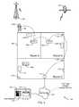
- FIG. 1illustrates an example system for collecting media exposure information and an example area in which audience members may be exposed to media presentations.
- FIG. 2Ais a block diagram of an example Multipurpose Personal Portable Metering device of FIG. 1 .
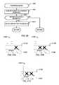
- FIG. 2Bis a block diagram of an example tag device of FIG. 1 .
- FIG. 2Cillustrates the example tag of FIG. 2B in a wearable format.
- FIG. 3is a block diagram of an example base unit for use in the system of FIG. 1 .
- FIG. 4Aillustrates an example communication process between the example Multipurpose Personal Portable Metering device of FIGS. 1 and 2A , and base unit of FIG. 1 .
- FIG. 4Billustrates an example communication process for use in the system of FIG. 1 .
- FIG. 4Cillustrates a flow diagram of an example process to calculate distance between the example Multipurpose Personal Portable Metering device of FIGS. 1 and 2A and the base unit of FIGS. 1 and 3 .
- FIGS. 5A and 5Billustrate example communication processes between the example tag device of FIGS. 1 and 2B , and the example base unit of FIGS. 1 and 3 .
- FIG. 5Cillustrates an example timing diagram for use with the example tag device of FIGS. 1 and 2B .
- FIG. 5Dillustrates a flow diagram of an example process to calculate distance between the example tag device of FIGS. 1 and 2B and the base unit of FIGS. 1 and 3 .
- FIG. 5Eillustrates a flow diagram of an example process to communicate status information from the example tag device of FIGS. 1 and 2B to the base unit of FIGS. 1 and 3 .
- FIG. 6illustrates a flow diagram of an example process for mesh communication in the system of FIG. 1 .
- FIG. 7is a block diagram of an example processor system that may be used to implement portions of the system of FIG. 1 .
- FIG. 8is a flow diagram of an example process to determine bandwidth capabilities of an example household of FIG. 1 .
- FIG. 9is a flow diagram of an example process to acquire audio information.
- FIGS. 10A , 10 B, and 11are flow diagrams of example processes to conserve battery power of the example Multipurpose Personal Portable Metering device of FIGS. 1 and 2A .
- FIG. 12is a flow diagram of an example process to determine media content broadcast in the example household of FIG. 1 .
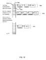
- FIG. 13is a diagram of example streams of signatures captured by a media monitoring center and a Multipurpose Personal Portable Metering device of FIGS. 1 , 2 A, and 3 .
- FIG. 14is a diagram of example audio segments captured by a Multipurpose Personal Portable Metering device of FIGS. 1 and 2A .
- FIG. 15is a block diagram of an example hash table for use in the system of FIG. 1 .
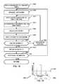
- FIG. 16is a flow diagram of an example process to find a match between reference data and metered data.
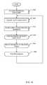
- FIG. 17is a flow diagram of an example process to load reference data into the example hash table of FIG. 15 .
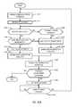
- FIG. 18is a flow diagram of an example process to match metered data with reference data.
- FIG. 19is an example histogram to compare offsets with a threshold.
- FIG. 20is a flow diagram of an example process to post-process match data.
- FIGS. 21A , 21 B, and 21 Care example histograms to compare offsets with a threshold.
- FIG. 22is a detailed view of the example compliance status device of FIG. 1 .
- the example methods and apparatus described hereinmay be used to analyze the movements and/or behaviors of audience members in the course of their exposure to media sources or media presentations to aid in determining whether such media presentations were actually consumed by the audience members.
- the audience membersmay be panelist members that are statistically selected to participate in a market research study.
- the audience membersneed not be panelist members. While mere proximity to media sources reflects an audience member's exposure, determining whether the audience member was paying attention to, consumed, and/or was engaged with such media sources requires more than proximity. For example, knowledge of an audience member's location of 5-feet from a media source (e.g., television) at one moment in time indicates exposure.
- a media sourcee.g., television
- Such an audience member detected 5-feet from the media source for several moments in timeindicates that the audience member may be consuming (e.g., engaged-with, paying attention to, etc.) the media presentation.
- location determinationallows valuable audience member data to be collected so that media exposure and/or consumption behavior may be determined.
- the methods and apparatus described hereinmay be used to determine if audience members are complying with Multipurpose Personal Portable Meters (MPPMs) carrying/wearing requirements or MPPM usage requirements.
- MPPMsMultipurpose Personal Portable Meters
- the example methods and apparatus described hereinmay also be used to manage communication procedures among the various MPPMs carried by the audience members. Such communication procedures, described in further detail below, prevent and/or minimize communication conflicts between MPPMs and other devices of the audience measurement system. Additionally, the methods and apparatus described herein may be used to determine the location and/or proximity of the various MPPMs carried by the audience members. As described in further detail below, location and/or proximity information may allow the MPPMs to more efficiently utilize on-board systems such that battery life is maximized.
- the example methods and apparatus described hereinmay be implemented using, for example, MPPMs worn or carried by audience members and location information systems (e.g., a global positioning system (GPS), RF towers/transceivers for triangulation, etc.), and may be used to collect audience member movement information and/or media exposure information and to analyze such movement and/or exposure information.
- the movement and/or exposure informationmay be detected relative to media sources (e.g., a set-top box, television, stereo, etc.) and used to determine the behavior of an audience member to determine if the audience member is sufficiently consuming media presentations.
- media presentationse.g., audio, video, still images, Internet information, computer information, etc.
- media presentationsmay be given appropriate media consumption credit.
- the example methods and apparatus described hereininclude a monitoring system that includes, but is not limited to, portable units to acquire media and/or audience member information.
- the portable units of the monitoring systemoperate in conjunction with various base units that are located in various rooms of a household.
- Portable unitsmay be feature rich and/or scaled down tags, as discussed in further detail below. Both the feature rich portable units and tags are capable of determining a distance of one or more audience members and the media delivery devices (e.g., televisions, home entertainment centers, stereos, etc.).
- the portable units, tags, and base units of the monitoring systemalso may operate in a mesh network to provide communicative functionality even when one of the devices is not within communicative proximity to a base unit, as discussed in further detail below.
- the monitoring systemalso determines communication bandwidth capabilities of the household, and may further adjust audio data processing accordingly to allow more efficient data transfers.
- the monitoring systemincludes various hash matching processes for broadcast programming identification.
- FIG. 1for purposes of clarity the example methods and apparatus are described herein with respect to an example geographic area 100 including indoor and outdoor regions that are associated with a household 102 . However, the example methods and apparatus described herein may be used in any area or environment.
- Location informationmay include, for example, geographic, global, or position coordinates that, when analyzed, may be used to determine the movements of a person or an audience member from one location to another.
- Location informationmay also include distances between an audience member and a media source, such as, for example, a home entertainment center, television, and/or a set-top box (STB) that resides in a household 102 .
- location informationmay be collected, obtained, generated, etc. using any suitable location detection devices, location detection systems, and/or location detection techniques. Specifically, the location detection devices described below may be worn or otherwise carried by a person or audience member and/or part of the MPPM.
- Media monitoring informationmay include any information associated with media that is consumed (e.g., viewed, listened to, interacted with, etc.) by an audience member.
- Media presentationsmay include, for example, television programming, radio programming, movies, songs, advertisements, Internet information, and/or any other video information, audio information, still image information, and computer information to which a person may be exposed via any media device (e.g., television, radio, Internet, in-store display(s), billboard(s), etc.).
- Media monitoring informationmay be generated based on, for example, audio codes, video codes, audio signatures, video signatures, radio frequency (RF) codes, and/or any other codes, signature information, or identifiers that may be extracted from or otherwise associated with a media presentation to which an audience member is exposed.
- RFradio frequency
- the example geographic area 100in which the example methods and apparatus of the present disclosure may operate, includes the example household 102 , which may contain multiple rooms and/or floors.
- the example geographic area 100 of FIG. 1also includes an example MPPM 104 worn by an audience member 106 . Additional example MPPMs 104 A, 104 B, 104 C, and 104 D (collectively referred to as “MPPMs 104 ”) are shown in FIG. 1 at various locations of the example geographic area 100 based on where the audience member is located.
- MPPMsmay operate both inside and outside the example household 102 , and employ various communication techniques and communication systems including, but not limited to, RF transceiver towers 108 and satellites 110 .
- the example household 102also includes a plurality of media delivery centers 112 A, 112 B, and 112 C (collectively referred to as “media delivery centers 112 ”), each of which may include one or more media delivery devices such as, for example, a television, a radio, etc. as well as a media playback device such as, for example, a DVD player, a VCR, a video game console, etc.
- media delivery centers 112may only include a single media delivery device.
- the example household 102may also include one or more location information systems such as, for example, a plurality of base units 114 A, 114 B, 114 C.
- the base units 114 A, 114 B, 114 Cmay also receive the MPPMs 104 for battery charging and/or data transfer operations, as discussed in further detail below.
- the base units 114may include one or more location based technologies (e.g., global positioning systems, radio frequency, optical, ultra-sonic, IR, Bluetooth®, etc.), some of which are described below and may be configured to work cooperatively with the MPPMs 104 to substantially continuously generate location information associated with the location of the example MPPM 104 D as the audience member 106 moves among various areas within, around, and/or outside the household 102 .
- the base units 114are configured primarily as stationary devices disposed on or near the media delivery centers 112 and adapted to perform one or more of a variety of well known media (e.g., television, radio, Internet, etc.) metering methods.
- the base units 114may be physically coupled to the media delivery centers 112 or may instead be configured to capture signals emitted externally by the media delivery centers 112 such that direct physical coupling to the media delivery centers 112 is not required.
- a base unit 114is provided for each media delivery center disposed in the household 102 , such that the base units 114 may be adapted to capture data regarding all in-home viewing by the audience members 106 .
- Information collected by the base units 114 and/or the MPPMs 104may be provided to a home processing system 116 .
- the home processing system 116may be communicatively coupled to one or more docking stations (not shown) configured to receive the MPPMs 104 and communicatively couple the MPPMs 104 to the home processing system 116 .
- audience members 106may periodically (e.g., nightly) place the MPPMs 104 in the docking stations to enable the home processing system 116 or base units 114 to obtain collected media monitoring information, location information, motion information, and/or any other information stored on the MPPMs 104 .
- Such information transfermay, additionally or alternatively, occur between the home processing system 116 and various MPPMs 104 via wireless and/or hardwired communications directly, and/or via one or more base units 114 .
- the docking stationsalso charge a battery of each the MPPMs 104 while the MPPMs 104 are docked thereto.
- the base units 114may operate as the home processing system 116 to collect information from other base units 114 and/or MPPMs 104 of the example household 102 .
- the home processing system 116(or a base unit 114 ) is further communicatively coupled to a central facility 118 via a network 120 .
- the network 120may be implemented using any suitable communication interface including, for example, a telephone system, a cable system, a satellite system, a cellular communication system, AC power lines, a network, the Internet, etc.
- the central facility 118is remotely located from the household 102 and is communicatively coupled to the household 102 and other monitored sites (e.g., other households) via the network 120 .
- the central facility 118may obtain media exposure data, consumption data, media monitoring data, location information, motion information, and/or any other monitoring data that is collected by various media monitoring devices such as, for example, the MPPMs 104 .
- the central facility 118may also record broadcast media at a relatively high (e.g., detailed) data rate to assist audio signature matching (e.g., audio, video, etc.) between various household monitored data and signatures monitored by the central facility 118 .
- the central facility 118may record broadcast media audio along with a timestamp. Monitored data that is received by various households may also contain audio signatures with a corresponding timestamp, which allow the central facility 118 to compare the timestamps and audio signatures to determine particular broadcast media monitored by the various households.
- the central facility 118includes a server 122 (i.e., a central processor system) and a database 124 .
- the database 124may be implemented using any suitable memory and/or data storage apparatus and techniques.
- the server 122may be implemented using, for example, a processor system similar or identical to the example processor system 812 depicted in FIG. 8 that is configured to store information collected from the MPPMs 104 and/or base units 114 in the database 124 and to analyze the information.
- the server 122may be configured to generate calibration information for the MPPMs 104 based on audio information or audio samples collected during an acoustic characterization process or calibration process performed within the household 102 .
- the central facility 118may also include rule modules 126 to configure monitoring equipment (e.g., MPPMs 104 , base units 114 , home processing systems 116 ) in conformance with regional parameters expected by the audience members. For example, monitoring systems in various geographic regions may include audience members 106 that speak different languages. As such, a rule module 126 that is employed to reflect regional preferences may propagate such preferences from the central facility 118 to each piece of monitoring equipment (e.g., MPPMs 104 , base units 114 , home processing systems 116 , etc.). Because each piece of monitoring equipment may include visual and/or audio prompts to communicate to the audience member, the regionally specific rule module 126 prompts the monitoring equipment to apply the appropriate language.
- monitoring equipmente.g., MPPMs 104 , base units 114 , home processing systems 116 .
- the rule modules 126may also dictate parameters such as, but not limited to, currency nomenclature, language dialects/accents, and data sample rates. For example, if certain geographic regions are less likely to include high-speed networks and/or internet services, the rule module 126 for that particular region may instruct all corresponding monitoring equipment to reduce the sample rate during data acquisition by the various metering devices (e.g., MPPMs 104 , base units 114 ).
- various metering devicese.g., MPPMs 104 , base units 114 .
- the household 102may also include an example compliance status device 128 that may be configured to obtain compliance status from the MPPM of each audience member in the household 102 and display the compliance status or provide an indication of compliance performance to the central facility 118 .
- the compliance status device 128includes a display that may be implemented using, for example, a plurality of LEDs and/or a display screen (e.g., CRT, LCD, etc.). Each of the LEDs may correspond to one of the audience members. Each LED may be configured to, for example, glow red when the corresponding audience member is non-compliant and glow green when the corresponding audience member is compliant.
- Each MPPMmay be configured to wirelessly transmit compliance status information directly to the compliance status device 128 and/or each MPPM may be configured to transmit compliance status information to a central collection facility (e.g., the central facility 118 described above), which may then communicate the compliance status information to the compliance status device 128 .
- the compliance status device 128may also be communicatively coupled to a home processing system (e.g., the home processing system 116 and/or base unit 114 described above).
- the compliance status systems disclosed in U.S. Application Ser. No. 60/613,646may also be used to determine compliance of audience members.
- each of the plurality of compliance status devicesmay be located in a respective room of the household 102 .
- Each compliance status devicemay be configured to indicate via, for example, LEDs, when an audience member is in the room corresponding to that compliance status device.
- An example interface for an example implementation of the compliance status device 128is illustrated in greater detail in FIG. 22 .
- the compliance status device 128may be a digital picture frame. Typically, a digital picture frame displays a random or ordered sequence of digital photos that an audience member places on the digital picture frame memory.
- the digital picture framemay be communicatively connected to a network of the household 102 (e.g., wired, wirelessly, network hub, router, etc.) and display digital pictures from an audience member's personal computer.
- a network of the household 102e.g., wired, wirelessly, network hub, router, etc.
- Such networked digital picture framemay also be communicatively connected to the home processing system 116 and/or the base units 114 to receive gentle reminder statements to urge or encourage compliance.
- the home processing system 116may send a gentle reminder command to the compliance status device 128 that causes a message to be displayed, such as “Please obtain your Portable Unit.”
- the home processing system 116 and/or the base units 114may monitor for trends exhibited by audience members 106 carrying the MPPMs 104 .
- the home processing system 116 and/or the base units 114may log location information of the MPPMs 104 and identify a trend that, for example, every workday at 6:50 AM the audience member 106 removes the MPPM 104 from its docking station and leaves the household 102 .
- the home processing system 116 and/or base units 114may automatically prompt the compliance status device 128 (e.g., the digital picture frame) to display a message at 6:51 AM if the MPPM 104 is still in its docking station, thereby indicating that the audience member 106 may have forgotten it.
- the digital picture framemay display a message at 6:51 AM that reads, “You have forgotten your Portable Unit! Please obtain it before leaving the house.”
- Location information and motion informationmay be continuously collected in indoor environments and/or outdoor environments via, for example, the example MPPMs 104 that may be carried or worn by an audience member 106 as shown in FIG. 1 .
- the example MPPM 104discussed in further detail in FIG. 2A , may be implemented as a standalone device having a pager-like design and/or integrated or jointly configured with a mobile telephone (e.g., a cordless telephone or a cellular-type telephone).
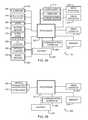
- FIG. 2Ais a block diagram of the example MPPM 104 of FIG. 1 .
- the MPPM 104may be used to monitor the media consumption activities of an audience member (e.g., the audience member 106 of FIG. 1 ) in addition to location information and motion information associated with those media consumption activities.
- the MPPM 104includes electronic components configured to detect and collect media monitoring information, location information, and motion information and communicates the information to the home processing system 116 and/or the central facility 118 ( FIG. 1 ) for subsequent analyses. As shown in FIG.
- the MPPM 104includes a processor 202 , a memory 204 , a communication interface 206 , a battery 207 , a plurality of media monitoring information sensors 208 , a plurality of location and motion sensors 210 , a plurality of audience alerts 212 , an input interface 214 , a visual interface 216 , a timer/counter 217 , and a comparator 234 , all of which are communicatively coupled as shown.
- the processor 202may be any processor suitable for controlling the MPPM 104 and managing or processing monitoring data related to detected media consumption or presentation information, location information, and/or motion information.
- the processor 202may be implemented using a general purpose processor, a digital signal processor, or any combination thereof.
- the processor 202may be configured to perform and control various operations and features of the MPPM 104 such as, for example, setting the MPPM 104 in different operating modes, controlling a sampling frequency for collecting media monitoring information, compressing collected tuning information, location information, and motion information, managing communication operations with other processor systems (e.g., the base units 114 , the home processing system 116 , the server 122 of FIG. 1 ), selecting location information systems (e.g., the RF transceiver tower 108 , the satellite 110 , and the base units 114 ), etc.
- other processor systemse.g., the base units 114 , the home processing system 116 , the server 122 of FIG. 1
- selecting location information systemse.g., the
- the memory 204may be used to store collected media monitoring information, program instructions (e.g., software, firmware, etc.), program data (e.g., location information, motion information, etc.), region specific data from the rule modules 126 , and/or any other data or information required to operate the MPPM 104 .
- program instructionse.g., software, firmware, etc.
- program datae.g., location information, motion information, etc.
- region specific datafrom the rule modules 126
- the processor 202may time stamp the acquired information and store the time-stamped information in the memory 204 .
- the memory 204may be implemented using any suitable volatile and/or non-volatile memory including a random access memory (RAM), a read-only memory (ROM), a flash memory device, a hard drive, an optical storage medium, etc.
- the memory 204may be any removable or non-removable storage medium.
- the communication interface 206may be used to communicate information between the MPPM 104 and other processor systems including, for example, the base units 114 (and/or charging/docking stations 114 ), the home processing system 116 , and/or the server 122 of FIG. 1 .
- the communication interface 206may be implemented using any type of suitable wired or wireless transmitter, receiver, or transceiver such as, for example, a Bluetooth® transceiver, an 802.11 (i.e., Wi-Fi) transceiver, a cellular communications transceiver, an optical communications transceiver, a network port, a universal serial bus (USB) port, etc.
- Communication between the MPPM 104 and the charging docking station 114may occur when the MPPM 104 is docked in the charging station 114 , for example, just before the audience member goes to sleep each night. Additionally, the base unit/charging station 114 and the MPPM 104 may communicate via a wireless interface, which may be particularly helpful if the audience member forgets to place the MPPM 104 on the charging station each night to charge the battery 207 and/or transfer measurement data. Without limitation, the base units 114 may operate as docking/charging stations 114 , a communication hub for the household 102 , and/or a data aggregator for other devices of the household 102 (e.g., MPPMs, TAGs, base units, docking stations, etc.).
- Such devicesmay be designated as a hub by virtue of an application programming interface (API) executed on a processor of the base unit 114 , charging station 114 , or home processing system 116 .
- APIapplication programming interface
- the docking stations/base units 114are typically powered via a household electrical outlet, which may provide communication to the other base units/docking stations 114 within the household 102 via any present and/or future powerline communication line protocols.
- the media monitoring information sensors 208include an audio sensor 218 , and optical transceiver 220 , and an RF transceiver 222 .
- the example MPPM 104via the audio sensor 218 , the optical sensor 220 , and/or the RF transceiver 222 , observes the environment in which the audience member 106 is located and monitors for media presentation and/or signals associated with media presentations.
- the example MPPM 104logs or stores a representation of the media content (e.g., a sample of detected portions of the content, a signature, a code, a replica, etc.) in the memory 204 and/or identifies the content, along with the time at which the content is detected.
- a representation of the media contente.g., a sample of detected portions of the content, a signature, a code, a replica, etc.
- the audio transducer 218may be, for example, a condenser microphone, a piezoelectric microphone or any other suitable transducer capable of converting audio information into electrical information.
- the optical transceiver 220may be, for example, a transmitter and receiver combination including a light sensitive diode, an IR sensor, a complimentary metal oxide semiconductor (CMOS) sensor array, a charge-coupled diode (CCD) sensor array, a light emitting diode (LED), etc.
- the RF transceiver 222may be, for example, a Bluetooth® transceiver, an 802.11 transceiver, an ultrawideband RF receiver, and/or any other RF receiver and/or transceiver. While the example MPPM 104 of FIG.
- the example MPPM 104need not include all of the sensors 218 , 220 , and 222 and/or may include other sensors.
- the audio sensor 218is sufficient to identify audio/video or program content via program characteristics, such as audio signatures or, if they are present, audio codes.
- the optical transceiver 220is sufficient to identify program content via program characteristics, such as video signatures or, if present, video codes.
- one particularly advantageous exampleincludes the audio sensor 218 and the optical transceiver 220 to enable audio and/or video monitoring (e.g., code and/or signature collecting).
- the location and/or motion sensors 210are configured to detect location-related information and/or motion-related information and to generate corresponding signals that are communicated to the processor 202 . More specifically, the location and/or motion sensors 210 may include an ultrasonic transceiver 223 , a motion sensor 224 , a satellite positioning system (SPS) receiver 226 , an RF location interface 228 , and/or a compass 230 . Additionally, the audio sensor 218 may be configured to receive ultrasonic signals from an ultrasonic source, such as an ultrasonic transmitter on a base unit 114 , other portable units 104 , and/or the home processing system 116 .
- an ultrasonic sourcesuch as an ultrasonic transmitter on a base unit 114 , other portable units 104 , and/or the home processing system 116 .
- location and/or motion sensors 210may be configured to receive location-related information (e.g., encoded information, pluralities of fragmented information, etc.) and/or to perform processing (either alone or in cooperation with the processor 202 ) to convert the received information to location information that indicates the location at which the MPPM 104 is located.
- location informationmay be derived using triangulation techniques, whereby the MPPM 104 may receive RF signals from three or more RF transmitters (e.g., three or more of the base units 114 of FIG. 1 ). In this case, a single RF signal from any one RF transmitter may be useless for generating location information.
- the location informationmay be generated by triangulating or processing a combination of RF signals from a plurality of RF transmitters.
- some of the location and/or motion sensors 210may be configured to process received location-related signals to generate location information and others of the location and/or motion sensors 210 may be configured to process the received location-related signals in combination with software executed on the processor 202 to generate location information.
- the location and/or motion sensors 210may not process data, but instead may communicate any received information to the processor 202 for processing.
- the ultrasonic transceiver 223may be used to allow the MPPM 104 and/or base units 114 to determine location information of the MPPM 104 . As discussed in further detail below, the ultrasonic transceiver 223 works in combination with the RF location interface 228 , RF transceiver 222 , and/or optical transceiver 220 to determine a distance between the MPPM 104 and a particular base unit 114 and/or home processing system 116 . For example, the MPPM 104 B (“MPPM B”) of FIG. 1 may transmit an ultrasonic chirp and RF signal simultaneously.
- the distance between the MPPM 104 B and the base unit 114may be calculated based on the time difference at which the chirps are detected, as described in further detail below.
- the motion sensor 224may be used to detect relatively small body movements of an audience member (e.g., the audience member 106 ), generate motion information related to the body movements, and/or to communicate the motion information to the processor 202 .
- the motion sensor 224may be implemented using any suitable motion detection device such as, for example, a mercury switch, a trembler, a piezo-gyroscope integrated circuit (IC), an accelerometer IC, etc.
- the SPS receiver (SPSR) 226may be implemented using, for example, a GPS receiver and may be configured to generate location information based on encoded GPS signals received from GPS satellites. In general, the SPS receiver 226 may be used by the MPPM 104 to collect location information in outdoor environments.
- the RF location interface 228may be implemented using a receiver or a transceiver and may be used to receive location-related signals or information from location information systems such as, for example, the RF transceiver tower 108 and/or the base units 114 .
- the RF location interface 228may also be configured to broadcast location-related information such as, for example, time-stamped MPPM identification codes.
- the time-stamped MPPM identification codesmay be received by, for example, three or more of the base units 114 , which may process the codes cooperatively using triangulation techniques to determine the location of the MPPM 104 .
- the base units 114may communicate to the home processing system 121 the received time-stamped MPPM identification codes along with information relating to the time at which the codes were received by each of the base units 114 .
- the home processing system 121may then determine the location of the MPPM 104 based on this information.
- the RF location interface 228may be implemented using any suitable RF communication device such as, for example, a cellular communication transceiver, a Bluetooth® transceiver, an 802.11 transceiver, an ultrawideband RF transceiver, etc.
- the RF location interface 228may be implemented using only an RF receiver or only an RF transmitter. Examples of known location-based technologies that may be implemented in cooperation with the RF location interface 228 include a Ekahau Positioning EngineTM by Ekahau, Inc. of Saratoga, Calif. and an ultrawideband positioning system by Ubisense, Ltd. of Cambridge, United Kingdom.
- the Bluetooth® transceivermay monitor the household 102 for Bluetooth® activity. For example, many wireless telephones and/or portable media players employ Bluetooth technology to enable wireless listening devices, such as speakers, headphones, and/or earpieces.
- the Bluetooth® transceivermay detect when such devices are being used, and thus determine whether an audience member 106 is consuming media, or whether the audience member 106 is merely proximate to the media source. For example, if the audience member 106 has a television turned on in Room A (of FIG.
- a typical audience measurement systemmay credit the audience member with viewing the show based on mere proximity to the television. However, if the user was talking on the telephone during the duration of the television show, then awarding credit to the audience member 106 may not be appropriate.
- the Bluetooth® transceiver within the MPPM 104 and/or within a base unit 114may detect such wireless phone earpiece activity, and deny credit to a user for viewing the television show.
- the compass 230may be implemented using a magnetic field sensor, an electronic compass integrated circuit (IC), and/or any other suitable electronic circuit.
- the compass 230may be used to generate direction information, which may be useful in determining the direction in which an audience member (e.g., the audience member 106 ) is facing.
- the direction informationmay be used to determine if a person is facing a television to enable consumption of a television program.
- the direction informationmay also be used to determine if a person is facing, for example, a billboard advertisement so that when the MPPM 104 receives an RF identification signal corresponding to the billboard advertisement and location information indicating that the audience member 106 is in front of the billboard, the direction information from the compass 230 may be used to determine if the audience member 106 is facing the billboard. In this manner, the billboard content may be credited appropriately for being consumed by a person.
- the plurality of audience alerts 212may be used to capture the attention of audience members (e.g., the audience member 106 of FIG. 1 ) to, for example, provide information to audience members and/or request input.
- audience memberse.g., the audience member 106 of FIG. 1
- the audience member 106may be prompted via one or more of the audience alerts 212 to indicate via the input interface 214 whether the audience member is consuming the detected media presentation or is merely in the vicinity of the detected media presentation.
- the audience member 106may be prompted to express approval or disapproval of a media presentation, or may submit his or her approval or disapproval without being prompted.
- any input informationcan also be used to credit a program with active consumption assuming that there is a positive correlation between opinion formulation and consumption (e.g., assuming people tend to formulate opinions on information that has actually been consumed and are less likely to formulate opinions on information to which they have merely been exposed).
- the MPPM 104may also include the input interface 214 , which may be used by an operator (e.g., the audience member 106 ) to input information to the MPPM 104 .
- the input interface 214may include one or more buttons or a touchscreen that may be used to enter information, set operational modes, turn the MPPM 104 on and off, etc.
- the input interface 214may be used to enter MPPM settings information, audience member identification information, etc.
- the MPPM 104may further include the visual interface 216 , which may be used, for example, in combination with the input interface 214 to enter and retrieve information from the MPPM 104 .
- the visual interface 216may be implemented using a liquid crystal display (LCD) that, for example, displays detailed status information, location information, configuration information, calibration information, etc.
- the visual interface 216may include light-emitting diodes (LEDs) that convey information including, for example, status information, operational mode information, etc.
- LEDslight-emitting diodes
- the timer/counter 217may be used to generate timer events that are communicated to the processor 202 . Timer events may be used to, for example, wake-up the MPPM 104 from a shut-down state, powered-down state, a power-saving mode state, etc.
- the timer/counter 217may be configured to generate a timing event after a particular amount of time has elapsed or at a particular time of day. The amount of time or time of day may be set by, for example, configuring registers in the timer/counter 217 .
- the comparator 234may be used to compare information.
- the MPPM 104may use the comparator to compare a locally stored identifier associated with the MPPM 104 with a received identifier communicated by a base unit 114 to determine if the base unit 114 is attempting to communicate with the MPPM 104 .
- the MPPM 104may also use the comparator 234 to compare any other information (e.g., time information, battery charge information, identification information, etc.). In some cases, the MPPM 104 may compare information to determine subsequent operations that the MPPM 104 should perform.
- the MPPM 104may use the comparator 234 to compare time or counter information from the timer/counter 217 to threshold values (e.g., minimum threshold values (zero) or maximum threshold values) to determine whether to perform, for example, wake up operations (e.g., wake up subsystems of the MPPM 104 ) or operations associated with placing subsystems of the MPPM 104 in a sleep mode.
- threshold valuese.g., minimum threshold values (zero) or maximum threshold values
- location information and motion informationmay also be continuously collected based on identification tags or metering tags (e.g., the example identification tag 250 of FIGS. 2B and 2C ).
- an identification tag 250may be worn or carried by an audience member (e.g., the audience member 106 ) and used in combination with or instead of the example MPPM 104 .
- the identification tag 250may be used to detect the location of the audience member 106 by configuring a location information system (e.g., the base units 114 of FIGS.
- identification tags 250may be used instead of the example MPPM 104 for battery conservation purposes. Typically, identification tags 250 contain fewer communicative features, location sensors, and/or motion sensors. As such, the identification tags 250 may operate for much longer periods of time and rely more heavily on the base units 114 for media logging.
- the example tag 250 of FIG. 2Bincludes a fewer number of on-board components and systems.
- FIG. 2Bis a block diagram of an example tag 250 that may be used instead of, or in addition to the example MPPM 104 of FIG. 2A . While the MPPM 104 of FIG. 2A includes many peripheral devices and features, the MPPM 104 of FIG. 2A also consumes more power than the example tag 250 of FIG. 2B .
- the example tag 250illustrates a trade-off between media monitoring functions performed by the base units 114 (and/or home processing system 116 ) and battery longevity of the portable metering device used.
- the tag 250 of FIG. 2Bincludes some of the same and/or similar components as the MPPM 104 of FIG. 2A , including a processor 252 , a memory 254 , a communication interface 256 , a battery 257 , an ultrasonic transceiver 258 , an optical transceiver 260 , a radio frequency (RF) transceiver 262 , a timer/counter 264 , and a comparator 266 all of which are communicatively coupled as shown.
- RFradio frequency
- the various transceiversinclude both a transmitter portion and a receiver portion.
- the optical transceiver 260may include a photodiode (light emitting diode, LED) for infra-red (IR) transmission and a photodetector for IR reception.
- IRinfra-red
- the MPPM 104may acquire media monitoring information at a data rate suitable for various aspects of the household 102 and/or geographic region.
- Many urban localitiesinclude an infrastructure of high speed internet access such as, for example, cable modems, digital subscriber line (DSL) modems, and/or wireless fidelity (WiFi) networks.
- DSLdigital subscriber line
- WiFiwireless fidelity
- Such high speed networking opportunitiesreduce bandwidth concerns for transmitting and/or receiving media monitoring information to/from the central facility 118 .
- the data (sample) rate of streams captured by MPPMs 104 and/or base units 114is 0.128 seconds per sample.
- sample ratesmay be selected based on factors such as the memory size of the MPPM and/or base unit 114 and/or a bit length of the captured media information.
- samples captured with a binary string length of 24-bitswill demand less bandwidth than 32-bit samples taken at the same sample rate.
- rural households without access to a high speed internet infrastructuremay rely on telephone modems to send and receive media monitoring information to/from the central facility 118 .
- the sample rate of the MPPMs 104 and/or base units 114may decrease accordingly to minimize transmission bandwidth and time that the telephone modem is on-line.
- the home processing system 116 and/or base units 114may detect and/or otherwise be aware of communicative limitations and adjust sample rates accordingly.
- the rule modules 126may also be aware of geographical areas in which sample rates should be lower and, in response to these communicative limitations, automatically configure household 102 devices to acquire media at a lower data rate.
- Adjusting sample rates in an example household 102may be implemented at various layers of functionality. For example, upon detection of a relatively low bandwidth home, the MPPMs 104 may be adjusted to reduce the rate of data capture in an effort to reduce the volume of information eventually transmitted to the central facility 118 . Additionally or alternatively, the base units/chargers 114 , upon receipt of the collected data from the MPPMs 104 , may apply data reduction technique and/or apply various compression algorithms to the data prior to transmission to the central facility 118 . Application of data reduction techniques and/or compression techniques within the example household 102 further help to minimize excessive bandwidth burdens on in-home networks.
- the MPPMs 104may be full-featured devices that, among other things, acquire audio data, compress the data, encrypt the data, compute the data to various signature formats, and/or compress the audio data into a lossless format
- the MPPMs 104may also scale-back their processing capabilities based on bandwidth parameters and/or battery longevity management.
- the MPPM 104may be configured as a datalogger to perform simple audio collection and compression (e.g., 32 kbps MP3, ADPCM, GSM, etc.) prior to data transfer to a base unit/charger 114 .
- the base unit/charger 114may, upon receipt of the data from the MPPMs 104 , complete the signature generation process, thereby relieving the MPPMs 104 of processing burdens, battery consumption burdens, and/or bandwidth burdens of the in-home network. Additionally, if alternate signature algorithms are designed and uploaded to an example household 102 from the central office 118 , such updated signature algorithms do not need to be uploaded to every device within the household 102 . Instead, a single device, such as a base unit 114 , a charging station 114 , or a home processing system 116 may store current and/or updated signature algorithms.
- such layered data reduction and processing distributionhas, at least, a two-fold benefit of improved MPPM 104 battery life, and reducing storage requirements of the MPPMs 104 and/or other base units/charging stations 114 in the household 102 .
- the media monitoring information collected by the MPPMs 104 , base units 114 , and/or home processing systems 116may be processed by the central facility 118 in real time or at a later time.
- the central facility 118may monitor and record broadcast information, such as codes (e.g., audio codes), signals (e.g., audio or video signals), signatures (e.g., a representation of an audio, video, or another source signal) from radio and/or television programs.
- codese.g., audio codes
- signalse.g., audio or video signals
- signaturese.g., a representation of an audio, video, or another source signal
- the central facility 118includes abundant memory resources (e.g., database 124 ) and high speed communication capabilities (e.g., high speed internet connections, T 1 trunk lines, etc.), the data acquisition rate may be much higher than that of the MPPMs 104 .
- the central facility 118typically acquires signatures/samples at a rate four times faster than that of the MPPMs 104 , e.g., 1 sample every 0.032 seconds.
- Such audio datais stored in one more or databases 124 and represents reference data that may be compared to media data acquired by the MPPMs so that broadcast content may be identified.
- Various matching algorithmsdiscussed in further detail below, seek to find the closest match between media data acquired by household 102 devices and reference data acquired by the central facility 118 .
- Ideal conditionsresult in a data sample acquired by the MPPM 104 , for example, exactly matching a data sample acquired by the central facility 118 . Furthermore, both samples ideally have an associated timestamp that is also identical. However, sample integrity from the MPPMs 104 is typically degraded by noise (e.g., environmental conditions) and/or sample bit length reductions to accommodate for bandwidth limitations. Furthermore, time stamps are generally offset due to the clocks within various household 102 hardware (e.g., MPPMs 104 , base units 114 , home processing system 116 ) not being synchronized and/or drifting.
- noisee.g., environmental conditions
- time stampsare generally offset due to the clocks within various household 102 hardware (e.g., MPPMs 104 , base units 114 , home processing system 116 ) not being synchronized and/or drifting.
- MPPMs 104that are not recharged prior to low battery voltage levels may experience an inability to maintain accurate clock time, thereby resulting in time differences between the MPPM 104 clock and the clock of the central facility 118 . Therefore, a Hamming distance (i.e., the number of bits that differ between two binary strings) of zero is preferred, but an unlikely reality. As discussed in further detail below, a hash matching algorithm allows an approximation to optimal matching algorithms while allowing an efficient tradeoff between accuracy and matching speed.
- the household 102 and the audience member 106 wearing the MPPM 104are located within the example geographic area 100 .
- the MPPM 104may be used to collect location information, motion information, and/or media monitoring information within the household 102 , outside of the household 102 (e.g., stores, shopping malls, restaurants, etc.), within structures other than the household 102 , outdoors, etc.
- the MPPM 104may be configured to substantially continuously generate, obtain, and/or collect media monitoring information, location information, and/or motion information.
- the MPPM 104may include one or more media detection devices used to detect presented media and to generate or collect media monitoring information or media-related data based on, for example, audio signals, video signals, RF signals, infrared (IR) signals, ultrasonic (US) signals, etc.
- the MPPM 104may include one or more location or positioning devices that enable the MPPM 104 to collect location or position information from one or more location information systems and/or to send location information to one or more location information systems.
- the example geographic area 100includes one or more location information systems that may be used to communicate location information to/from the MPPM 104 .
- the location information collected by the MPPMs 104also allow more efficient audience member data processing than may occur on a media monitoring side (MMS), such as at the central office 118 .
- Samplese.g., video samples, audio samples, etc.
- Reference broadcast datae.g., reference broadcast data
- the MMSmay need to search a large database prior to finding a match.
- the MPPMs 104include an SPS receiver 226 that determines geographic locality information so that searches by the MMS may be focused on particular geographic subsets of the database, thereby improving identification efficiency and reducing search time.
- the Chicago nativemay be credited for media consumption behavior while on the business trip.
- the location information systemsmay be implemented using, for example, one or more radio frequency (RF) transceiver towers represented in FIG. 1 by the RF transceiver tower 108 and/or one or more satellites represented in FIG. 1 by a satellite 110 .
- RFradio frequency
- the interior environment of the household 102 or other monitored location 102may include one or more location information systems described below.
- the MPPM 104may collect media monitoring information (e.g., codes, signatures, etc.) associated with any media (e.g., video, audio, movies, music, still pictures, advertising, etc.) to which the audience member 106 is exposed.
- media monitoring informatione.g., codes, signatures, etc.
- the MPPM 104may be configured to obtain audio codes, generate or collect signatures, etc. that may be used to identify video programs (e.g., DVD movies, television programming, etc.), audio programs (e.g., CD audio, radio programming, etc.), etc.
- the MPPM 104may collect media monitoring information associated with media presented or delivered by one or more of the media delivery centers 112 and to which the audience member 106 may be exposed.
- the MPPM 104may be configured to receive audio codes and/or RF codes associated with other forms of media such as, for example, billboards (not shown) or any other form of publicly viewable advertising or media.
- each billboardmay include an audio broadcasting device and/or an RF broadcasting device configured to emit a billboard code that uniquely identifies that billboard. If the MPPM 104 is proximate to a billboard, the MPPM 104 may obtain the billboard code as media monitoring information, thereby indicating that the audience member 106 was exposed to the billboard.
- the MPPM 104may be configured to obtain direction information via, for example, an electronic compass, and log the direction in which the audience member 106 was facing or traveling so that subsequent data analyses may determine if the audience member 106 was likely facing the billboard and, thus, exposed to the billboard's content.
- the RF transceiver tower 108may be used in combination with any RF communication technology such as, for example, a cellular or mobile communication technology (e.g., GSM, CDMA, TDMA, AMPS, etc.)
- the RF transceiver tower 108may be configured to transmit or broadcast position information and/or any type of signal that may be used by the MPPM 104 to generate location information.
- the RF transceiver tower 108may transmit information having geographic location information and time codes. More specifically, the RF transceiver tower 108 may be associated with a particular or unique set of geographic location coordinates (i.e., geographic location information), that define or indicate the location of the RF transceiver tower 108 within a global positioning grid.
- the time codesmay be associated with a time at which a particular signal is transmitted by the RF transceiver tower 108 .
- the geographic location information and the time codes received from a plurality of RF transceiver towersmay be used by the MPPM 104 to perform one or more triangulation processes to determine the location(s) of the MPPM 104 . Triangulation processes are well known in the art and, thus, are not described further herein.
- the RF transceiver tower 108is depicted as being located in an outdoor environment, the MPPM 104 may include location technologies that communicate with the RF transceiver tower 108 when the MPPM 104 is located within indoor environments (e.g., within the household 102 ) or outdoor environments.
- the satellite 110may also be used to communicate location information to/from the MPPM 104 .
- the satellite 110may be used to implement any satellite positioning system (SPS) such as, for example, the global positioning system (GPS) that continuously broadcasts position-related information.
- SPSsatellite positioning system
- GPSglobal positioning system
- the MPPM 104may receive the position-related information from the satellite 110 to determine movement information associated with the location(s) of the MPPM 104 .
- the memory of the example tag 250 of FIG. 2Btypically stores a minimal amount of information such as, for example, a unique tag identification number that corresponds with one of the audience members.
- the communication interface 256may be used to communicate information to the tag 250 , such as uploading a unique identification number to the memory 254 , setting the timer/counter 264 with a date and time, and/or synchronizing the timer/counter 264 with other devices of the example household 102 and/or the central facility 118 .
- the battery 257 of FIG. 2Bmay be much smaller.
- FIG. 2Cillustrates an example identification tag 250 implemented in the shape of a credit card or key chain.
- the example tag 250 of FIG. 2Cincludes an electronic system-on-chip (SOC) 270 and audience member identification indicia 272 .
- the electronic SOC 270may include a memory 254 , RF circuitry, infra-red (IR) circuitry 260 , ultrasonic (US) circuitry 258 , radio frequency (RF) circuitry 262 , comparator 266 , and, in some implementations, a processor 252 .
- IRinfra-red
- USBultrasonic
- RFradio frequency
- the memory 254may be used to store audience member identification information and the RF circuitry, IR circuitry 260 , and/or US circuitry 258 may be used to transmit the audience member identification information from the memory 254 to one or more of the base units 114 .
- the electronic SOC 270may be configured to be powered via RF emissions transmitted by, for example, the base units 114 .
- the identification information 272may be printed, engraved, or otherwise put on a surface of the identification tag 250 .
- the identification information 272may be the name of an audience member or an identification number corresponding to the audience member.
- the identification information 272may be the same information that is stored in the memory of the electronic SOC 270 .
- Each audience member of a householdmay be instructed to wear or carry an identification tag that is substantially similar or identical to the identification tag 250 .
- an audience membermay be instructed to clip an identification tag to each of their most frequently carried or worn belongings.
- a plurality of identical (e.g., all having the same audience member identification information printed thereon and/or stored in the electronic SOC 270 ) identification tagsmay be issued to each audience member.
- Each audience membermay then clip or store each identification tag in, for example, a purse, a jacket, shoes, a belt, a wallet, a key chain, etc.
- the identification tag 250may include a key chain hole 274 that may be used to attach the identification tag 250 to a set of keys. Clipping, attaching, or storing an identification tag in each of an audience member's most frequently used belongings ensures that the audience member will always carry or wear an identification tag. Additionally or alternatively, the identification tag 250 may be small and integrated as a pendant, bracelet, and/or any other type of jewelry. Incorporating the tag 250 as a piece of jewelry further promotes audience member 106 compliance and ensures that the audience member will more frequently wear the tag 250 .
- the example MPPM 104may include one or more location detection devices and/or motion detection devices as described above in connection with FIG. 2A that the MPPM 104 may use to monitor the audience member 106 and/or determine MPPM 104 location information.
- the location detection devices and/or motion detection devicesmay be configured to enable the example MPPM 104 to collect audience member location information and/or motion information in indoor environments and/or outdoor environments. In this manner, when an audience member moves among indoor areas and outdoor areas a substantially continuous location/motion history may be tracked or logged for each audience member and subsequently analyzed to develop movement information.
- FIG. 3is a block diagram of one of the example base units 114 of FIG. 1 .
- the example base units 114may be used to communicate information to the MPPM 104 , the home processing system 116 , and/or the central facility 118 of FIG. 1 .
- the example base unit 114includes a processor 302 , a memory 304 , and a plurality of sensors and/or transducers 306 .
- sensors and/or transducers 306include an RF location transceiver 308 , an ultrasonic transceiver 310 , an optical sensor and/or transmitter (e.g., transceiver) 312 , and an audio transducer 314 .
- the example base unit 114also includes a remote transceiver 316 that receives the monitoring data collected by the base unit 114 and/or received by a MPPM 104 and sends it to, for example, the home processing system 116 ( FIG. 1 ) and/or the central facility 118 ( FIG. 1 ).
- the example base unit 114 of FIG. 1also includes a MPPM interface 318 , an input interface 320 , a visual interface 322 , and a memory 324 , all of which may be communicatively coupled to the processor 302 as shown.
- the processor 302may be used to control and/or perform various operations or features of the base unit 114 and may be implemented using any suitable processor, including any general purpose processor, digital signal processor (DSP), or any combination thereof.
- the processor 302may be configured to receive location information, motion information, and/or media monitoring information from the MPPM 104 .
- Information collected(by either the MPPM 104 and/or the base unit 114 ) may be stored in the memory 324 and communicated to the home processing system 116 and/or directly to the central facility 118 .
- the processor 302may also be configured to control communication processes that occur between the base unit 114 and other processing systems (e.g., the MPPM 104 , the home processing system 116 , and the server 122 ). For example, the processor 302 may provide location-related information to MPPMs via the RF location transceiver 308 . In addition, the processor 302 may control the reception of media monitoring information, location information, motion information, etc. from the MPPM 104 via the MPPM interface 318 and store the information in the memory 324 . The processor 302 may then cause the remote transceiver 316 to communicate the monitoring data to, for example, the home processing system 116 ( FIG. 1 ) and/or the central facility 118 ( FIG. 1 ). Additionally, the processor 302 and/or the memory of the base unit 114 may be programmed to carry out the process of FIGS. 4C , 5 D, 6 , 8 - 12 , 16 - 18 , and/or 20 below.
- FIGS. 4C5 D, 6 , 8
- the memory 324is substantially similar or identical to the memory 204 ( FIG. 2A ) and may be used to store program instructions (e.g., software, firmware, etc.), data (e.g., location information, motion information, media monitoring information, etc.), and/or any other data or information.
- program instructionse.g., software, firmware, etc.
- datae.g., location information, motion information, media monitoring information, etc.
- the RF location interface 308may be implemented using a transmitter, a receiver, or a transceiver and configured to transmit and/or receive location-related information and may be configured to communicate with the RF location interface 228 ( FIG. 2A ) of the MPPM 104 .
- the RF location interface 308may transmit location-related codes to the MPPM 104 , which may receive encoded location-related codes from various base units to determine location coordinates indicative of the location of the MPPM 104 .
- the RF location interface 308may receive location-related codes from the MPPM 104 and, as described above, may work in cooperation with other base units and/or the home processing system 116 to determine the location of the MPPM 104 . Where multiple MPPMs are present, each MPPM is assigned a unique code to enable the base structures to distinguish MPPMs when detecting locations.
- the RF location interface 308may be implemented using any suitable RF communication device such as, for example, a cellular communication transceiver, a Bluetooth® transceiver, an 802.11 transceiver, an ultrawideband RF transceiver, etc.
- the RF location interface 308may be used in combination with any of the known location-based technologies described above (e.g., the Ekahau Positioning EngineTM by Ekahau, Inc. and the ultrawideband positioning system by Ubisense, Ltd.).
- the RF location interface 308may be configured to receive and/or transmit any form of location-related information including location coordinates and/or any other information associated with known location-based technologies.
- the MPPM interface 318is substantially similar or identical to the communication interface 206 of FIG. 2A and may be configured to communicate information between the base unit 114 and one or more MPPMs (e.g., the MPPM 104 of FIGS. 1 and 2A ).
- the MPPM interface 318may be any wired or wireless transceiver such as, for example, a Bluetooth® transceiver, an 802.11 transceiver, an Ethernet transceiver, a universal asynchronous receiver-transmitter (UART), a cellular communication transceiver, etc.
- the input interface 320 and the visual interface 322 of the base unit 114may be substantially similar or identical to the input interface 214 and the visual interface 216 , respectively, of FIG. 2A .
- the remote transceiver 316may be used to communicate information between the base unit 114 and, for example, the home processing system 116 ( FIG. 1 ) and/or the central facility 118 ( FIG. 1 ).
- the remote transceiver 316may be communicatively coupled to the network 120 and may be implemented using any suitable wired or wireless communication transceiver including, for example, a telephone modem, a DSL modem, a cable modem, a cellular communication circuit, an Ethernet communication circuit, an 802.11 communication circuit, a powerline modem, etc.
- the remote transceiver 316may be used to communicate media monitoring information (e.g., audio samples, codes, and/or signatures), location information, and/or motion information to the home processing system 116 and/or the central facility 118 via the network 120 .
- media monitoring informatione.g., audio samples, codes, and/or signatures
- FIG. 4AAn example communication between the base unit 114 and the MPPMs 104 for determining the location of the MPPMs 104 is shown in FIG. 4A .
- the base unit 114is separated by a distance “x” from the MPPM 104 .
- the base unit 114initiates a location determination process (distance determination) by emitting a chirp 405 , which includes a simultaneous radio frequency (RF) chirp with an ultrasonic (US) chirp.
- RFradio frequency
- USultrasonic
- the base unit 114may transmit the RF chirp with the RF location interface 308 and transmit the US chirp with the US transducer 310 .
- the RF chirp transmitted by the base unit 114may further include an embedded base unit 114 identifier.
- RF signalselectromagnettic radiation
- the RF chirp propagation timeis, for all practical purposes, instantaneous because it travels at the speed of light, thus the MPPM 104 receives the RF chirp first and initiates a timer 217 .
- the MPPM 104is “armed” and waiting to detect the US chirp via the US transducer 223 .
- audio sampling rates of computers, PDAs, and other audio hardwaretypically exceeds 8000 samples per second. Such a sample rate yields a resolution of 0.125 milliseconds per sample, which is sufficient for purposes of audience member distance determination.
- the MPPM 104Upon receipt of the US chirp by the MPPM 104 , the MPPM 104 stops the timer and calculates the distance between the base unit 114 and MPPM 104 as a function of the elapsed time and the known propagation rate of sound. If necessary, or if varying degrees of accuracy are desired, adjustments to the calculation may be implemented to accommodate for variations in air temperature, ambient pressure, and/or atmospheric density. Such calculations are stored in the memory 204 of the MPPM 104 and executed by the processor 202 to yield the distance “x.” The calculated distance is then stored in the memory 204 for later communication to the base unit 114 .
- the MPPM 104after calculating and storing the distance between itself and the base unit 114 , retrieves the distance measurement from the memory 204 and transmits it to the base unit 114 as an encoded RF and/or IR signal 410 .
- the MPPM 104may also embed an MPPM identifier so that the base unit 114 may identify which distance value is associated with which MPPM. Additionally or alternatively, the MPPM 104 may transfer the distance measurement results to the base unit 114 when the MPPM 104 connects to the charging/docking station 114 (e.g., at the end of the day).
- Such redundant information transfermay ensure that data from the MPPM 104 is not missed by, for example, bursts of RF and/or IR noise that may interfere with wireless data transmission. While both the MPPM 104 and the base unit 114 may each store the distance measurement results in their respective memories, the MPPM 104 may delete such calculation results from its memory 204 after the MPPM 104 docks with the charging station 114 , typically at the end of the day. Similarly, the charging station/base unit 114 may delete such distance measurement results from memory 324 after such results are transferred to the central office 118 , another base unit 114 configured as a household hub, and/or the home processing system 116 .
- the base unit 114 and MPPM 104may, additionally or alternatively, repeat the distance determination process any number of times to verify an accurate measurement. For example, five iterations of the distance determination process may proceed in which the MPPM 104 calculates an average from the five samples. The average distance value is then transmitted to the base unit 114 via an encoded RF signal 410 . Still further, the MPPM 104 may send the raw elapsed time data back to the base unit 114 rather than perform such calculations on the processor 202 . The relay of raw data back to the base unit 114 rather than on-board calculation by the MPPM 104 may allow the MPPM 104 to consume less power for calculations and/or reduce the memory 204 size requirements.
- the base unit 114may perform the distance determination process in a MPPM-specific manner. For example, the base unit 114 may simultaneously send the RF and/or US chirp to the MPPM 104 with a MPPM identification code embedded in the RF and US signals 405 . As such, only the MPPM 104 having the matching identity of the encoded RF chirp will arm to receive the US signal. Alternate MPPM(s) that do not have the matching identification code will ignore the RF chirp and will not initiate their timer(s) 217 .
- the encoded US chirpis decoded by the MPPM 104 having the matching identification code to cause the MPPM 104 to stop its timer 217 upon receipt.
- multiple MPPMssuch as MPPM A 104 A, MPPM B 104 B and MPPM C 104 C may independently execute a distance determination process, even if such MPPMs are in RF and/or US proximity to each other.
- the base unit 114may, instead, transmit the RF or IR chirp without a corresponding US chirp.
- the base unit 114may transmit the RF chirp and initiate the timer 217 .
- the transmitted RF chirpis immediately received by the MPPM 104 , which may then transmit a US chirp in response to receiving the RF chirp.
- the base unit 114stops its timer 217 in response to receiving the US chirp and calculates the distance “x” based on the elapsed time.
- the base unit 114includes four ultrasonic transceivers 310 a , 310 b , 310 c , and 310 d .
- the example MPPM 104includes four ultrasonic transceivers 223 a , 223 b , 223 c , and 223 d .
- the example ultrasonic transceivers 310 a - dmay determine direction information of the MPPM 104 .
- a US chirp transmitted by the MPPM 104is first received by transceivers 310 a and 310 b , and at some time later the US chirp is received by transceivers 310 c and 310 d .
- the base unit 114may then identify an orientation of the MPPM 104 based on the temporal delay of the US chirp between the transceivers 310 a - d.
- the base unit 114transmits the US chirp
- the four US transceivers 223 a - dwill receive the chirp at different times based on the orientation of the transceivers 223 a - d with respect to the transmitted US chirp.
- US transceivers 223 a and 223 breceive the US chirp transmitted by the base unit 114 at substantially the same time.
- the US transceivers 223 c and 223 dwill receive the US chirp at some time later than US transceivers 223 a and 223 b , thereby indicating a source direction of the transmitted US chirp.
- the various base units 114 of a household 102may operate on a “round-robin” configuration to prevent communication interference between various metering devices within the household 102 .
- the base units 114 and MPPMs 104do not implement the encoded RF and US chirps, as described above, then any base unit 114 that transmits an RF chirp may cause all of the MPPMs 104 to start their respective timers 217 because (unlike localized US signals) RF signals typically propagate through walls of a household 102 without significant attenuation.
- communication interferencemay be minimized or eliminated by ensuring that only one base unit 114 emits the simultaneous RF and US chirp at a time.
- FIG. 4Billustrates an example round-robin communication process for four example base units 114 A, 114 B, 114 C, and 114 D (collectively “ 114 ”) that may reside in a household 102 or other monitored location (e.g., a store).
- Each of the base unitshas a dedicated amount of time during which it may send and/or receive data to/from the various MPPMs 104 .
- only one of the four base unitsmay transmit (via the RF location interface 308 , the ultrasonic transceiver 310 , the optical transceiver 312 , and/or the audio transducer 314 ) to the MPPMs 104 .
- Such dedicated time-slotsrestrict communication between base units and MPPMs, but do not interrupt and/or interfere with any abilities of the other base units and/or other MPPMs performing metering operations, such as logging audio signals from the various media delivery centers 112 .
- base unit A 114 Abegins a periodic loop by having exclusive permission to send and/or receive communication signals to the MPPMs 104 .
- none of base unit B, base unit C, or base unit Dmay send the simultaneous RF and US chirp for the purpose of distance determination.
- a time-slot for base unit B 114 Bpermits exclusive permission to perform the aforementioned distance determination process without interference from other base units 114 .
- the round-robin loopproceeds to base unit C 114 C and later to base unit D 114 D before repeating the round-robin loop again beginning with base unit A 114 A.
- base units 114are communicatively coupled to one another. Marshalling of the round-robin protocol may be accomplished by assigning one device, such as base unit A 114 A, for example, as the primary device and all remaining devices as secondary. Alternatively, any other device that is communicatively connected to the base units 114 may operate as the primary to marshal the round-robin protocol, including, but not limited to, the home processing system 116 . Persons of ordinary skill in the art will appreciate that a round-robin network sharing protocol may be administered in any number of ways and will not be discussed herein further.
- each MPPM 104may be configured to time-out after a predetermined amount of time has elapsed from the initial RF chirp if no corresponding US chirp is detected. For example, if the speed of sound for a particular household is assumed to be 1086 feet per second, then a MPPM 104 time-out of 0.027 seconds will allow rooms less than 30 feet to be measured. Time delays in excess of 0.027 seconds suggest that the US chirp may have propagated beyond the boundaries of the room, thus may be ignored.
- FIG. 4Cis a flow diagram of an example method that may be used to calculate distance between the MPPM 104 and the base unit 114 .
- the base unit 114 and MPPM 104determine distance by a combination of RF and US chirps (see 405 and 410 of FIG. 4A ).
- the base unit 114initiates a location determination process (distance determination) by emitting a chirp 405 , which includes a simultaneous radio frequency (RF) chirp with an ultrasonic (US) chirp (block 415 ).
- RFradio frequency
- USultrasonic
- the base unit 114fails to receive a responsive RF chirp back from the MPPM 104 , the MPPM 104 is presumed to be out of range of the household 102 (block 420 ). As discussed below in view of FIG. 13 , if the MPPM fails to receive an RF or US chirp from the base unit 114 , then the MPPM 104 activates its GPS engine and inertial motion sensors (block 425 ). Because the base unit 114 is typically connected to a powerline outlet, power conservation issues are of little concern and the base unit 114 may attempt to locate a MPPM 104 continuously. The MPPM 104 , on the other hand, does not continuously transmit an RF or US chirp so that battery power is conserved.
- blocks 415 , 420 , and 425may iterate at periodic intervals in a constant effort to search for MPPM 104 devices within range of the household 102 .
- Each base unit 114 of the household 102may emit a periodic chirp in a round-robin manner to prevent communication interference, as discussed above in view of FIG. 4B .
- the round-robin communication processpermits each base unit 114 a dedicated amount of time in which communications between itself and the MPPM 104 may occur. Typically, the dedicated amount of time is sufficient for a distance calculation between a single pair of base unit 114 and MPPM 104 .
- the MPPM 104detects the RF chirp (block 420 )
- the MPPMinitiates a timer (block 430 ). Because the RF chirp propagation time is, for all practical purposes, instantaneous because it travels at the speed of light, the MPPM 104 receives the RF chirp first and initiates a timer 217 before the US chirp has an opportunity to reach the MPPM 104 . As such, the MPPM 104 is effectively “armed” and waiting to detect the US chirp via the US transducer 223 (block 435 ).
- the MPPM 104may enter into a timing loop to wait for the US chirp to arrive, such an US chirp may never arrive due to a variety of factors. For example, RF signals typically propagate through walls of a household 102 with relative ease, but US signals typically require a significantly closer proximity. If the US chirp fails to arrive at the MPPM after a predetermined timeout period, the MPPM 104 may return to its previous operating state (e.g., monitoring audio data).
- the MPPM 104upon receipt of the US chirp by the MPPM 104 (block 435 ), the MPPM 104 stops the timer (block 440 ) and calculates the distance between the base unit 114 and MPPM 104 as a function of the elapsed time and the known propagation rate of sound (block 445 ). If necessary, or if varying degrees of accuracy are desired, adjustments to the calculation may be implemented to accommodate for variations in air temperature, ambient pressure, and/or atmospheric density. Such calculations are stored in the memory 204 of the MPPM 104 and executed by the processor 202 to yield the distance “x.” The calculated distance is then stored in the memory 204 for later communication to the base unit 114 .
- the MPPM 104after calculating and storing the distance between itself and the base unit 114 , retrieves the distance measurement from the memory 204 and transmits it to the base unit 114 as an encoded RF or IR signal 410 (block 450 ). As discussed in further detail below, the MPPM 104 deactivates its GPS and inertia sensors (block 455 ) because it is within range of the household 102 , i.e., a known location that typically does not require GPS location techniques.
- Location determinationmay also be accomplished with the example tag 250 .
- An example communication between the base unit 114 and the tag 250 of FIG. 2B for determining the location of the tag 250is shown in FIG. 5A .
- the tag 250 of FIG. 2Bmay be used in addition to, or instead of the example MPPM 104 shown in FIG. 2A .
- the tag 250 of FIG. 2Binitiates the location determination process (distance determination) by emitting an infra-red (IR) pulse 505 to the base unit 114 .
- IRinfra-red
- IR pulsesmay be emitted by the tag 250 , with an embedded tag identification signal, on a periodic basis and consume very small amounts of power from the battery 257 . If the base unit 114 is within a line-of-sight range of the tag 250 and receives the IR pulse 505 with the optical receiver portion of the optical transceiver 312 , the base unit 114 returns an acknowledgement pulse 510 back to the tag 250 with the transmitter portion of the optical transceiver 312 . The acknowledgement IR pulse signal 510 confirms to the tag 250 that it is within range to perform location determination.
- the tag 250transmits an IR chirp and an US chirp 515 to the base unit 114 at substantially the same time.
- IR signalsmuch like the RF signals described above, propagate at the speed of light and, for practical purposes, can be considered instantaneous.
- the US chirpon the other hand, propagates at a much slower speed so that the difference of the propagation times between the IR and US chirps may be used to calculate the distance “x” between the tag 250 and the base unit 114 in the manner described above.
- the example tag distance determination process shown in FIG. 5Ais particularly useful for audience measurement techniques when battery power needs to be conserved. Such power conservation may allow longer periods of time for audience measurement in between battery charging and accommodate the forgetful user that fails to place the tag 250 on a charging dock (e.g., a charging station/base unit 114 combination) on a regular basis (e.g., every night).
- the power of the tag 250is conserved by issuing a burst of US energy (chirp) 515 only when a base unit 114 is within range. Additionally, battery 257 power is conserved by offloading distance calculations from the tag 250 to the base unit 114 .
- FIG. 5Aillustrates the tag 250 initiating an IR chirp 505
- the base unit 114may, alternatively, initiate the process of distance determination with the tag 250 , as shown in FIG. 5B .
- the optical transceiver 228includes a photodetector that consumes less energy than the periodically emitting IR LED transmitter described above in view of FIG. 5A
- the base unit 114may periodically transmit the IR chirp instead of the tag 250 , thereby optimizing the conservation of battery 257 power. This also conserves power at the tag because the tag 250 will not chirp IR pulses to see if a base unit is present, but instead will wait to receive an IR pulse from a base unit before transmitting a chirp.
- the base unit 114 of FIG. 5Binitiates the distance determination process by sending an IR chirp 520 from its optical transceiver 312 that is received by the optical receiver portion of the optical transceiver 260 of the tag 250 if the tag 250 is present.
- the tag 250 of the illustrated exampleresponds by sending a simultaneous IR chirp and US chirp 525 to the base unit 114 . Accordingly, the distance between the tag and the base unit 114 may be calculated by the base unit 114 in the same manner as described above, thereby minimizing processing and memory requirements of the tag 250 .
- Tags 250may interfere with each other when attempting to communicate. As described above, communication conflicts may be minimized by using encoded (tag identification) signals, synchronizing devices to communicate at independent times from each other, and/or establishing a round-robin communication protocol. Such methods to prevent communication conflict may be particularly useful when battery power is not of great concern and/or when such devices are communicatively connected together on a network, either wired or wireless. Because the tags 250 are not typically part of a communication network and because the tags 250 of the illustrated example cannot afford to consume great amounts of battery 257 power by constantly transmitting and receiving synchronization signals from a network, the tags 250 of the illustrated example employ a variable transmission rate to minimize collision during communication attempts. FIG.
- 5Cillustrates three example transmission rates 250 A, 250 B, and 250 C, each of which is associated with a tag.
- the tag associated with transmission rate 250 Aperforms communication functions once every, for example, 2.70 seconds.
- the tags associated with transmission rates 250 B and 250 Cperform communication functions once every 2.82 and 2.94 seconds, respectively.
- Such non-uniform transmission rates 250 A, 250 B, 250 Cpermit communication attempts by the various tags at times in which no other tags are simultaneously attempting to communicate. For example, at time t 1 , only the tag associated with transmission rate 250 A is attempting to communicate. Similarly, at time t 2 , only the tag associated with transmission rate 250 B is attempting to communicate, and at time t 3 , only the tag associated with transmission rate 250 C is attempting to communicate. While overlap of communication attempts is not completely prevented by this approach, as shown by example time t 4 in which the tags associated with rates 250 A and 250 C overlap, such times of overlap are reduced because of the dissimilar transmission rates for each of the tags. In particular, while time t 4 experienced an overlap, the tag associated with rate 250 A experiences no overlap at the next period iteration of time t 5 .
- FIG. 5Dis a flow diagram of an example method that may be used to calculate distance between the tag 250 and the base unit 114 .
- the base unit 114 and tag 250determine distance by a combination of IR and US chirps (see, for example, 505 and 515 of FIG. 5A ).
- the tag 250is programmed to emit an IR pulse at periodic intervals, as discussed above in view of FIG. 5C . Because each tag 250 of the example household 102 is programmed with a different transmission rate (e.g., one tag that transmits every 2.70 seconds, a second tag that transmits every 2.82 seconds, etc.) communication overlap is reduced.
- the tag 250When the transmission rate of the tag 250 repeats its periodic interval (block 530 ), the tag 250 initiates a location determination process by emitting an IR pulse 505 to the base unit 114 (block 535 ). Each IR pulse 505 emitted by the tag 250 consumes a very small amount of battery power, thereby allowing the tag 250 to operate away from a charging/docking station for long periods of time. The tag 250 waits a predetermined amount of time (timeout) for a response from the base unit 114 (block 540 ).
- timeouta predetermined amount of time
- the tag 250waits for the next iteration of its transmission rate (block 530 ) before emitting another IR chirp in search for the base unit 114 (block 535 ).
- the base unit 114if the base unit 114 is within a line-of-sight range of the tag 250 (block 540 ) and receives the IR pulse 505 with the optical receiver portion of the optical transceiver 312 , the base unit 114 returns an acknowledgement pulse 510 (block 545 ) back to the tag 250 with the transmitter portion of the optical transceiver 312 .
- the acknowledgement IR pulse signal 510confirms to the tag 250 that it is within range to perform location determination.
- the tag 250transmits a simultaneous IR chirp with an US chirp to the base unit 114 (block 555 ).
- IR signalsmuch like the RF signals described above, propagate at the speed of light and are, for present practical purposes, instantaneous.
- the US chirpon the other hand, propagates at a much slower speed so that the difference of the propagation times between each chirp may be used to calculate the distance “x” between the tag 250 and the base unit 114 .
- the base unit 114waits to receive the IR chirp from the tag 250 (block 560 ) and starts its timer (e.g., a timer function of the processor 302 ) upon receipt of the IR chirp 515 from the tag 250 (block 565 ). While the base unit 114 waits for the US chirp (block 570 ), the timer value increases proportionally with the distance separating the base unit 114 from the tag 250 that emitted the US chirp 515 . Upon receipt of the US chirp 515 , the base unit stops the timer and uses the resulting time value to calculate distance (block 575 ).
- timere.g., a timer function of the processor 302
- the tag 250may be configured to communicate status information (e.g., battery level information, movement history information, etc) to a requesting base unit (e.g., the base unit 114 of FIG. 5B ) in response to receiving a status request message from the base unit.
- the tag 250may transmit its status information to the base unit 114 using infrared (IR) transmissions.
- IRinfrared
- the tag 250requires relatively more power than required to perform other operations (e.g., receive RF transmissions).
- Configuring the tag 250 to communicate its status information only when it is requested to do so by the base unit 114enables putting most or all of the electrical subsystems of the tag 250 in a sleep mode (e.g., shutting down or disabling some or all of the electrical subsystems to consume relatively less or no electrical power) to conserve the stored energy (e.g., battery life) in a battery of the tag 250 . Otherwise, if the tag 250 were configured to transmit its status information unconditionally (e.g., at predefined intervals) the battery charge of the tag 250 would more quickly decrease and many of the status information transmissions may be wasted if the tag 250 were not sufficiently close to a base unit for the base unit to detect the transmissions.
- the tag 250is provided with an RF transceiver configured to receive status requests from base units.
- a sleep modesome or all of the electrical subsystems of the tag 250 may be shut down.
- the tag 250may keep the RF transceiver powered or at least partially powered (e.g., the antenna interface circuitry and receiver circuitry may be powered) to detect RF signals.
- the tag 250can receive RF signals including status requests from base units and, in response, communicate its status information to a requesting base unit.
- base unitsmay be configured to include a tag ID of a particular tag from which status information is to be requested.
- a base unitcan specify a particular tag each time the base unit requests status information.
- the tag 250can remain in a sleep mode if the tag 250 determines that its assigned tag ID does not match the tag ID in the received status request. If multiple tags are present in the same room or within the communication vicinity of the same base unit, all of the tags need not exit sleep mode or respond each time the base unit transmits a status request.
- the status informationincludes battery level information and movement history information.
- the status informationmay additionally or alternatively include other information such as, for example, media identification information corresponding to media presentations to which the tag 250 was exposed, location information, room identification information, etc.
- the battery level informationcan include, for example, status bits indicative of the amount of energy or charge remaining in the battery of the tag 250 .
- the movement history informationcan include bits corresponding to values or data indicative of whether and when the tag 250 was moved, which may be indicative of a person's activity while wearing or carrying the tag 250 .
- the tag 250may be configured to generate and/or collect movement information in any manner described herein each time the tag 250 is moved and to store the movement information for subsequent communication to a base unit.
- the tag 250may be configured to tag each movement information entry with a timestamp of when a corresponding movement occurred.
- the movement history informationcan be configured to include only movement information that was generated since a last time the tag 250 communicated status information to the base unit 114 or any other base unit.
- the tag 250may be configured to clear movement information from a buffer or memory each time it communicates status information.
- the status information exchangescan be implemented using substantially the same techniques described herein. For example, although the status information exchanges are described as occurring between the tag 250 and one or more of the base units 114 , in other example implementations, the status information exchanges can be implemented to occur between the MPPM 104 and one or more of the base units 114 . Additionally or alternatively, the status information exchanges can be implemented to occur between the tag 250 and one or more people meters or between the MPPM 104 and one or more people meters.
- a people meteris an electronic device that is typically disposed in the presentation area of a presentation device (e.g., a television) and that is proximate to one or more audience members.
- Some example people metersare adapted to communicate with a media meter disposed in, for example, a set top box, that measures various signals associated with the television for a variety of purposes including, but not limited to, determining the operational status of the television (i.e., whether the television is off or on) and identifying the programming being displayed by the television. Based on any number of triggers, including, for example a channel change or an elapsed period of time, the people meter prompts the audience member(s) to input information by depressing one of a set of buttons each of which is assigned to represent a different member. For example, the people meter may prompt the audience member(s) to register (i.e., log in) or may prompt the audience member(s) to indicate that they are still present in the audience.
- the people metermay prompt the audience member(s) to register (i.e., log in) or may prompt the audience member(s) to indicate that they are still present in the audience.
- the above exampleis applicable to television audience measurement and/or to other
- FIG. 5Eis a flow diagram representative of example machine readable instructions that may be executed to communicate status information from the tag 250 to the base unit 114 .
- the base unit 114determines whether it should transmit a status request message (block 576 ).
- the base unit 114may be configured to transmit a status request message to the tag 250 at predefined time intervals and/or in response to one or more events. If the base unit 114 should not yet transmit a status request message, it continues to check at block 576 to determine when it should transmit a status request message.
- the base unit 114determines that it should transmit a status request message (block 576 )
- the base unit 114selects a tag ID of the tag (e.g., the tag 250 ) from which it is to receive status information (block 578 ).
- the base unit 114then transmits the status request with the selected tag ID via an RF signal (block 580 ).
- the tag 250receives the status request and the tag ID (block 582 ) via its RF interface 262 and, in response, wakes up its comparator subsystem 266 (block 584 ).
- the RF interface 262can generate an interrupt or trigger signal, or a receive buffer in which the RF interface 262 stores the status request can generate an interrupt or trigger signal indicating the status request has been received.
- an interrupt handler or trigger signal handlercan wake up the comparator subsystem 266 .
- a polling routine or a data receive monitorcan be configured to periodically check a receive buffer for receipt of a status request message.
- the tag 250in response to a receive data interrupt, a receive data trigger signal, or determining that data has been received in the receive buffer, the tag 250 can wake up its comparator subsystem 266 .
- the comparator subsystem 266determines whether the received tag ID matches the tag ID assigned to the tag 250 (block 586 ) by comparing the tag ID's. For example, the comparator subsystem 266 can receive the tag ID from the RF interface of the tag 250 , retrieve the tag ID of the tag 250 from a memory of the tag 250 , and compare the received and retrieved tag ID's to each other. If the comparator subsystem 266 determines that the tag ID's match (block 586 ), the tag 250 wakes up additional tag subsystems necessary to respond to the status request (block 588 ).
- the tag 250can wake up an IR interface, a microprocessor, etc. by communicating a wake up signal (e.g., an interrupt) from the comparator subsystem 266 to the subsystems to be woken up.
- a wake up signale.g., an interrupt
- the tag 250can wake up a battery status subsystem and/or a movement status subsystem.
- the battery status subsystemcan be configured to measure a battery charge remaining in its battery or batteries so that the tag 250 can communicate a battery status to the base unit 114 .
- the movement status subsystemcan be configured to determine whether any movement history information is available for communication to the base unit 114 .
- the tag 250then generates status data including battery level information (block 590 ). If the tag 250 has been moved since the last time it communicated status information to a base unit (block 592 ), the tag 250 adds any available movement information in the status data (block 594 ). More specifically, when the tag 250 is moved, the tag 250 may generate movement information (e.g., movement history information) indicative of its movement and store the movement information in a memory. In some example implementations, at block 592 , the tag 250 can determine that it has moved after it communicated previous status information to a base unit if any movement information is stored in its memory 254 , and each time the tag 250 communicates status information to a base unit, the tag 250 can clear its memory 254 of movement history information.
- movement informatione.g., movement history information
- the tag 250when the tag 250 generates and stores new movement information it can set a flag indicating that movement information is available for communication to a base unit, and after the tag 250 communicates status information (and the movement history information) to a base unit, the tag 250 can clear the flag. In this manner, at block 592 , if the flag is set, the tag 250 can determine that new movement information generated after previous status information was communicated to a base unit is available. On the other hand, if the flag is clear, the tag 250 can determine that no movement information has been generated after the tag 250 communicated status information to a base unit.
- the tag 250After the tag 250 adds the movement information in the status data (block 594 ) or if the tag 250 determines that it has not been moved since the last time it communicated status information (block 592 ), the tag 250 transmits the status data to the base unit 114 via IR (block 596 ). After the tag 250 transmits the status data to the base unit 114 , the tag 250 places its subsystems in sleep mode (block 598 ) while keeping awake (or in standby mode) only the subsystem(s) or circuitry (e.g., an RF antenna interface and an RF receiver interface) required to detect RF transmissions from base units. The process of FIG. 5E then ends.
- the example process of FIG. 5Eis described above as the base unit 114 transmitting the status request via an RF signal at block 580 and the tag 250 transmitting the status data to the base unit 114 via an IR signal at block 596 .
- the base unit 114can be configured to transmit the status request using any other type of transmission signal at block 580
- the tag 250can be configured to transmit the status data to the base unit 114 using any other type of transmission signal at block 596 different from the type of transmission signal used by the base unit 114 at block 580 .
- the base unit 114may be configured to transmit the status request using an RF signal at block 580
- the tag 250may be configured to transmit the status data using an ultrasonic signal at block 596 .
- the data from the MPPM 104is forwarded to a central office for out of home reporting and fixed-location metering information (e.g., media metering information generated by the base units 114 ) associated with the MPPM 104 is also forwarded to the central office to provide metered location (e.g., in home) information for analyzing.
- metered locatione.g., in home
- the in-home datai.e., data collected at one or more primary monitored locations such as a panelist's home
- the out-of-home datai.e., data collected outside the primary monitored location(s) generated by the MPPM 104 may be processed together and/or independently to provide comprehensive information regarding the metered audience exposure.
- the example geographic area 100in which the example household 102 and/or store 102 is located includes multiple rooms (e.g., Rooms A, B, and C) and/or floors.
- some of the example devices to meter an audiencemay not be within communicative range of another device.
- an audience member in proximity to the media delivery center 112 A carrying MPPM A 104 A of Room Ais not in communicative range of any base unit 114 .
- the audience member 106 carrying a MPPM 104 Dis not within communicative range of a base unit 114 because, for example, the user is gardening outside the example household 102 .
- an MPPM 104 and/or a base unit 114includes a memory to store audience member data
- the memory requirements of such deviceincrease in size (and the expense) as a function of increasing time away from a docking station and/or any other device (e.g., base unit, home processing system) that may communicatively receive collected audience data. Therefore, it is desirable to provide a vehicle for transmitting data from the MPPM or tag to reduce on-board memory requirements.
- FIG. 1illustrates a mesh network to expand the communicative capabilities of various devices (e.g., MPPMs, tags, base units, charging station, docking stations, home processing system, etc.) to meter an audience.
- devicese.g., MPPMs, tags, base units, charging station, docking stations, home processing system, etc.
- each MPPM 104 (or tag), base unit/charging station 114 , and/or home processing systemmay operate as a repeater to relay communications.
- audience member 106is well out of range of the nearest base unit 114 (Room B), the audience member 106 is within range of MPPM A 104 A in Room A.
- the MPPM 104 Dmay communicate audience member data (e.g., GPS location information via satellite 110 and/or RF transceiver towers 108 ) and/or other information to MPPM A 104 A in Room A.
- audience member datae.g., GPS location information via satellite 110 and/or RF transceiver towers 108
- other informatione.g., information about MPPM A in Room A.
- the MPPM Arelies upon MPPM B 104 B in Room B to service communicative needs.
- MPPM A 104 Auses MPPM B 104 B to forward its data (and/or data received from the MPPM 104 D) to the base station 114 A.
- MPPM B 104 Bis within communicative range of the base unit 114 of Room B, it can relay communicative requests and/or data from any one of the MPPM 104 of the outside user 106 , MPPM A 104 A of Room A, and/or any other MPPM within its communication range.
- the base unit 114 of Room B(which may operate as a metering device), much like base units 114 in other location(s) of the example household 102 , may be communicatively networked together via a local network.
- a local networkmay further the home processing system 116 and the charging/docking stations.
- the local networkmay include wired or wireless techniques known by persons of ordinary skill in the art (e.g., 802.11 wireless, Bluetooth®, Category 5 network cable, powerline communication, X10 protocol, cellular, etc.).
- the local networkenables data sharing and/or transfer between any two elements of the network, although such communication may be via an intermediate node or element.
- FIG. 6is a flow diagram of an example method that may be used to permit mesh communication among the various devices of the example household 102 .
- one or more of the MPPMs 104 and/or base units 114may operate as a repeater to relay communications from one device (e.g., an MPPM) to another device (e.g., a remotely located base station).
- a given MPPM 104is within direct communicative range of a base unit 114 (block 605 )
- datamay be transferred to/from the base station by using any of the communication methods as described above (block 610 ).
- the MPPM 104may transfer data from the optical transducer 220 , and/or the RF transceiver 222 .
- the MPPM 104may determine whether a docking station is within communication range (block 615 ). For example, the audience member 106 may have placed the MPPM 104 on the docking station to allow it to charge during the night.
- any data that resides on the memory 204 of the MPPM 104may be uploaded to the base unit 114 via the networked docking station (block 620 )
- the MPPM 104may determine whether it is within communication range of another MPPM 104 (block 625 ).
- the MPPM 104includes various sensors and transducers that may aid in location of and/or communication with other devices that also employ such sensing technology.
- the MPPM 104may employ its RF transceiver 222 to detect another MPPM 104 in range, as discussed above in view of FIG. 1 .
- data stored in memory 204may be RF modulated and transmitted to the other MPPM 104 to enable the other MPPM to act as a relay (block 630 ).
- the MPPM 104fails to locate another MPPM 104 within communicative range, that MPPM 104 may wait for another opportunity in which it may be closer to any one of a base unit 114 , docking station, and/or another MPPM 104 to convey data.
- a system for wirelessly conveying data to a base unit using MXLis discussed in Internation Application No. PCT/US04/00818, which is hereby incorporated by reference in its entirety.
- FIG. 7is a block diagram of an example processor system 710 that may be used to implement the apparatus and methods described herein.
- the processor system 710includes a processor 712 that is coupled to an interconnection bus 714 .
- the processor 712includes a register set or register space 716 , which is depicted in FIG. 7 as being entirely on-chip, but which could alternatively be located entirely or partially off-chip and directly coupled to the processor 712 via dedicated electrical connections and/or via the interconnection bus 714 .
- the processor 712may be any suitable processor, processing unit or microprocessor.
- the system 710may be a multi-processor system and, thus, may include one or more additional processors that are identical or similar to the processor 712 and that are communicatively coupled to the interconnection bus 714 .
- the processor 712 of FIG. 7is coupled to a chipset 718 , which includes a memory controller 720 and an input/output (I/O) controller 722 .
- a chipsettypically provides I/O and memory management functions as well as a plurality of general purpose and/or special purpose registers, timers, etc. that are accessible or used by one or more processors coupled to the chipset 718 .
- the memory controller 720performs functions that enable the processor 712 (or processors if there are multiple processors) to access a system memory 724 and a mass storage memory 725 .
- the system memory 724may include any desired type of volatile and/or non-volatile memory such as, for example, static random access memory (SRAM), dynamic random access memory (DRAM), flash memory, read-only memory (ROM), etc.
- the mass storage memory 725may include any desired type of mass storage device including hard disk drives, optical drives, tape storage devices, etc.
- the I/O controller 722performs functions that enable the processor 712 to communicate with peripheral input/output (I/O) devices 726 and 728 and a network interface 730 via an I/O bus 732 .
- the I/O devices 726 and 728may be any desired type of I/O device such as, for example, a keyboard, a video display or monitor, a mouse, etc.
- the network interface 730is communicatively coupled to the network 120 and may be, for example, an Ethernet device, an asynchronous transfer mode (ATM) device, an 802.11 device, a DSL modem, a cable modem, a cellular modem, etc. that enables the processor system 710 to communicate with another processor system.
- ATMasynchronous transfer mode
- memory controller 720 and the I/O controller 722are depicted in FIG. 7 as separate functional blocks within the chipset 718 , the functions performed by these blocks may be integrated within a single semiconductor circuit or may be implemented using two or more separate integrated circuits.
- FIGS. 8-12 , 16 - 18 , and 20are flow diagrams that depict example processes.
- the example processes depicted in the flow diagrams of FIGS. 8-12 , 16 - 18 , and 20may be implemented in software, hardware, and/or any combination thereof.
- the example processesmay be implemented in software that is executed on the MPPMs 104 of FIGS. 1 and 2A , the tags 250 as shown in FIG. 2B , the base units 114 of FIGS. 1 and 3 , and/or the processor system 710 of FIG. 7 .
- the example processesare described below as a particular sequence of operations, one or more operations may be rearranged, added, and/or removed to achieve the same or similar results.
- FIG. 8is a flow diagram of an example method that may be used to improve collection and analysis of media monitoring information and location information.
- the example method of FIG. 8may be implemented using a base unit (e.g., the base unit 114 of FIGS. 1 and 3 ).
- the base unit 114may be configured to monitor the network 120 for bandwidth capacity based on a data rate measurement during data transmission and reception. Transmission and reception rates for monitored locations (e.g., stores, audience member households) 102 that employ a telephone modem will be relatively low as compared to households 102 that employ a cable or DSL modem.
- a household 102 with a low bandwidth connection to the network 120indicates that each device in the household 102 that performs data collection should be configured to reduce its sample rate and activate data compression techniques, if available.
- the processor 302 of the base unit 114may analyze and acquire the transmission and reception rates for data traffic to/from the example household 102 via the remote transceiver 316 (block 805 ).
- the acquired sample ratemay be stored in the base unit 114 memory 324 along with an aggregate number of samples. More than one sample is particularly helpful to prevent a false understanding of data transmission capabilities for the example household 102 .
- the base unit 114will inform and/or instruct other devices (e.g., MPPMs 102 , tags 250 , base units 114 ) to sample measurement data at a very high rate.
- the acquired sample rate, or the aggregate sample rate (e.g., a running average) saved in the memory 304is compared against a data rate threshold to determine whether the speed communication capabilities (e.g., high, low, etc.) (block 810 ). If the threshold value, such as a data rate of 500 kilobits per second (kbps), is lower than the rate measured (e.g., the running average), then the household 102 has a relatively fast network connection as compared to a household using dial-up modems. Accordingly, the presence of such a high data rate prompts the base unit 114 to instruct the devices to sample at a high/maximum sample rate and disable data compression algorithms, if any (block 815 ).
- a data rate thresholdsuch as a data rate of 500 kilobits per second (kbps)
- the threshold valueis higher than the rate measured, then the household may have a relatively slow network 120 connection as compared to a household using cable or DSL modems. Accordingly, a lower data rate may prompt the base unit 114 to instruct the devices (e.g., MPPM 102 , tags, base unit 114 ) to sample at a lower/minimum sample rate and employ data compression algorithms (block 820 ). Multiple thresholds may be used to throttle the sample rate and/or the level of compression to a level consistant with the available data rate to/from the monitored location 102 .
- FIG. 9is a flow diagram of an example method that may be used to acquire audio information by a device (e.g., MPPM 102 , tag, base unit 114 ) related to content viewed and/or heard by audience members.
- a MPPM 104 and/or a base unit 114may be configured to acquire audio signals of the broadcast program(s) (e.g., television, radio, etc.) being presented to by the audience member.
- the broadcast program(s)e.g., television, radio, etc.
- the following flow diagramwill be described in view of the MPPM 104 as the device that monitors audio data.
- other devicese.g., a tag, a base station, etc.
- the audiois recorded by the MPPM 104 (block 905 ) and compressed into an audio file format (block 910 ) such as, but not limited to, audio video interleave (AVI), WAVE (WAV) format by Microsoft®, audio interchange file format (AIFF), Windows® media audio (WMA), and/or MPEG audio layer-3 (MP3) format.
- an audio file formatsuch as, but not limited to, audio video interleave (AVI), WAVE (WAV) format by Microsoft®, audio interchange file format (AIFF), Windows® media audio (WMA), and/or MPEG audio layer-3 (MP3) format.
- AVIaudio video interleave
- WAVWAVE
- AIFFaudio interchange file format
- WMAWindows® media audio
- MP3MPEG audio layer-3
- the compressed audio fileis encrypted (block 915 ) to prevent the acquired audio data from being accessed by an unauthorized party.
- the MPPM 104 carried by the audience memberis lost or stolen, then the privacy of the audience member is less likely to be breached by another person because of the encryption.
- the process of acquiring datacontinues (blocks 905 , 910 , 915 ).
- the MPPM 104uploads the compressed and/or encrypted audio data in a manner consistent with the bandwidth capabilities of the example household 102 (block 925 ). For example, if the household 102 is determined to have a limited bandwidth capability, then any data sent to the central facility 118 is left in a compressed format and/or further compressed before transmission (block 930 ). As described above, based on the bandwidth capability determination of the household, the sample rate of audio recorded (block 905 ) may have been previously set to a low rate (block 820 of FIG. 8 ). Similarly, the compression setting (block 910 ) may also be adjusted pursuant to the communicative capabilities of the example household 102 (block 820 of FIG. 8 ).
- the MPPM 104is placed on the docking station (block 920 ) and the capabilities of the example household 102 indicate that high speed communication options are available (e.g., high speed internet via cable or DSL modem), then, prior to sending the metering data to the central facility 118 , the encrypted data is decrypted (block 935 ). Thereafter, the decrypted data is decompressed (block 940 ), which permits the MPPM 104 , base unit 114 , or home processing system 116 to generate signatures and/or extract codes (block 945 ) that may have been embedded in the acquired broadcast signal.
- high speed communication optionse.g., high speed internet via cable or DSL modem
- the central facility 118is less inundated/taxed with processing responsibilities upon receipt of such metering data.
- portable metering unitssuch as the MPPM 104 and/or the tag 250 , consume varying amounts of battery power based on the activities they perform.
- the MPPM 104consumes a greater amount of battery power when, for example, the audio sensor 218 , the optical transducer(s) 220 , the RF transceiver 222 , the US transducer 223 , the motion sensor 224 , and/or the SPSR 226 are active.
- all of the various sub-components of the portable deviceare not necessary at all times of operation.
- the various example location determination methods described aboveallow the portable devices to conserve on-board battery power by selectively powering down sub-systems based on the detected location of the portable meter.
- FIG. 10Ais a flow diagram of an example method that may be used to conserve battery power of the MPPM 104 .
- the base unit 114is emitting periodic RF, IR, and/or US chirps in an effort to locate the portable devices (e.g., MPPMs 104 , tags 250 ). If the MPPM 104 fails to receive an RF chirp (block 1005 ) from the base unit 114 , then the MPPM 104 turns off its internal devices related to audio acquisition (block 1010 ).
- the MPPM 104is presumed to be outside the boundaries of a monitored location (e.g., a household, store, restaurant, etc.) 102 , in which case the internal devices related to GPS location detection are activated (block 1015 ) to enable data collection indicative of where the user (e.g., audience member) has traveled. For example, while the user may not be within the household 102 (or other metered location) to view and/or listen to media programming (e.g., radio, television, etc.), the user may be in the vicinity of various billboards, mall advertisements, and/or supermarket ads.
- GPS location detection methodsallow collection of exposure to outside advertisements based on proximity.
- the MPPM 104detects an RF chirp from the base unit 114 (block 1005 ), but fails to detect a corresponding US chirp (block 1020 ), then the internal devices related to audio detection and/or collection are turned on (block 1025 ).
- the MPPM 104may also be far enough away to indicate that the user is not in the vicinity of one or more media delivery centers 112 . Nonetheless, audio detection may still be useful in the event that the user is listening to a portable radio, MP3 player, etc. while, for example, gardening outside or working in a garage workshop.
- the MPPM 104is receiving RF chirps from the base unit 114 , it may be safely assumed that the MPPM is located near the monitored location 102 and the internal devices related to GPS location detection and/or inertial detection may no longer be needed and may then be turned off (block 1030 ) to conserve battery power.
- the MPPM 104may turn off both the internal devices for audio detection, GPS location detection, and inertial systems (block 1035 ).
- the base unit 114 and MPPM 104may determine a distance, as described above in view of FIGS. 4A , 4 B, 4 C, 5 A, 5 B, 5 C, and 5 D, and then unload further data acquisition responsibilities to the base unit 114 .
- the base unit 114may collect all audio data from the media delivery center 112 , extract codes and/or collect signatures, and store the collected data, codes, and/or signatures in the memory 324 for later transmission to the home processing system 116 (if available) and/or the collected data, codes, and/or signatures may be transmited directly to the central facility 118 .
- Battery power of the MPPM 104is conserved due to its reliance upon the base unit 114 for most of the data acquisition (metering functions) while in proximity to the base station.
- the MPPM 104may also conserve battery power based on a voltage measurement of the battery.
- FIG. 11is a flow diagram of an example method that may be used to conserve MPPM 104 battery power.
- clock speed variationshave an effect on battery longevity in devices that employ processors, such as the processor 202 in the example MPPM 104 .
- processorssuch as the processor 202 in the example MPPM 104 .
- any given processorhas a finite amount of resources (e.g., transistors), wherein use of such transistors requires switching power.
- the clock speed of a processorincreases, the amount of switching power per unit of time increases, thereby increasing the power consumption and heat generation of the processor.
- the clock speed decreaseslower amounts of power are required per unit of time.
- the MPPM 104 of the illustrated exampleperiodically performs a voltage measurement on the internal battery 207 and compares the measured voltage to a voltage threshold that indicates a battery strength status. If the battery threshold voltage is lower than the measured voltage (e.g., the voltage measurement is above the threshold value) (block 1105 ), then the clock speed of the MPPM 104 processor 202 is maintained at its present (i.e., “normal”) rate (block 1110 ). However, if the battery measurement is measured and falls below the threshold value (block 1105 ), then the MPPM 104 processor 202 clock speed is reduced to consume less power per unit of time.
- a voltage thresholdthat indicates a battery strength status. If the battery threshold voltage is lower than the measured voltage (e.g., the voltage measurement is above the threshold value) (block 1105 ), then the clock speed of the MPPM 104 processor 202 is maintained at its present (i.e., “normal”) rate (block 1110 ). However, if the battery measurement is measured and falls below the threshold value (block 1105 ), then the MP
- Various thresholdsmay be established and stored in the memory 204 of the MPPM 104 .
- a battery voltage threshold valuemay be set to accommodate for the relatively rapid discharge rate after a slight voltage decrease is measured.
- the battery voltage threshold valuemay be set to accommodate the more linear discharge rate exhibited by such batteries.
- FIG. 10Bis a flow diagram representative of example machine readable instructions that may be executed to conserve battery power of the MPPM 104 .
- the example instructions of FIG. 10Bmay also be used to generate information indicative of when the MPPM 104 was within a home or out of a home.
- the MPPM 104may be configured to turn off or shutdown its media detection subsystems or circuitry (e.g., the information sensors 208 of FIG. 2A ) when they are not needed to detect media information.
- the MPPM 104may use the communication interface 206 ( FIG. 2 ) to determine when it is located within a home or out of a home. In the illustrated example of FIG.
- the communication interface 206is implemented using a Bluetooth® (BT) transceiver having discovery capabilities similar or identical to those defined in the Bluetooth® standard. These capabilities are employed to determine when the MPPM 104 is near one of the base units 114 of FIG. 2 in the household 102 (or other metered location).
- BTBluetooth®
- the MPPM 104enables its communication interface 206 (block 1042 ) and broadcasts a discovery inquiry message (block 1044 ).
- the communication interface 206may broadcast a discovery message as defined in the Bluetooth® standard.
- the MPPM 104determines whether it has received a response (block 1046 ) from a base unit (e.g., one or more of the base units 114 of FIG. 1 ). For example, if the MPPM 104 , is sufficiently close to one of the base units 114 so that the base unit 114 can receive the discovery message, the base unit 114 is configured to respond by communicating a response message to the MPPM 104 .
- the MPPM 104determines whether the response has a relevant ID (block 1050 ). In the illustrated example, the MPPM 104 determines whether the response has a relevant ID by using the comparator 234 to compare an identifier received via the response to a locally stored identifier associated with the MPPM 104 .
- the base units 114may be configured to insert an ID value (e.g., a system ID value or a shared ID value which is shared between some or all metering devices in the household 102 ) that indicates that the base units 114 are associated with the metering applications or the metering system.
- an ID valuee.g., a system ID value or a shared ID value which is shared between some or all metering devices in the household 102
- non-relevant wireless devicessuch as, for example, BT-enabled telephones or computers or MPPM's not corresponding to the same monitored environment or the same metering system as the MPPM 104 that respond to the discovery message will not include the ID value.
- the MPPM 104will ignore response messages received from such non-relevant devices.
- the MPPM 104determines that the received message does have a relevant ID value (block 1050 )
- the MPPM 104creates an “in-home” entry and stores the same in the memory 204 ( FIG. 2A ) (block 1052 ).
- the MPPM 104can include a timestamp in the “in-home” entry to indicate that the MPPM 104 was inside the household 102 (or other metered location) at the time it created the “in-home” entry.
- the “in-home” entryindicates that the MPPM 104 was within an area (e.g., a monitored environment) having a stationary metering device (e.g., one of the base units 114 ) therein.
- the “in-home” entrydoes not necessarily mean that the MPPM 104 is within a household.
- the “in-home” entrymay indicate that the MPPM 104 is within any other area (e.g., an office, a retail establishment, etc.) having stationary metering devices capable of interacting with the MPPM 104 and performing media metering, audience metering, and/or other metering applications substantially similar or identical to the MPPM 104 .
- the same metering entity or metering companymay install various metering systems in various areas (indoor or outdoor) having base units substantially similar or identical to the base units 114 and capable of communicating with the MPPM 104 and other MPPM's, each of which may be associated with a different household.
- Stored entries indicating an “in-home” statuscan be subsequently analyzed to determine the times during which the MPPM 104 was located within the household 102 (or within another building having base units similar to the base units 114 ).
- the MPPM 104then disables the media detection circuitry (e.g., disables one or more of the information sensors 208 of FIG. 2A ) (block 1054 ). In this manner, the MPPM 104 can offload all media detection and collection processes to the base unit(s) 114 and, in turn, the MPPM 104 can conserve its battery power by relying upon the base unit 114 to perform data acquisition (metering functions) while the MPPM 104 is within the household 102 (or other metered location).
- the media detection circuitrye.g., disables one or more of the information sensors 208 of FIG. 2A
- the base unit 114may collect media signals from the media delivery center 112 , extract codes and/or collect signatures, and store the same in the memory 324 for later transmission to the home processing system 116 (if available) or transmit the collected metering information (e.g., collected codes and signatures) directly to the central facility 118 .
- the base units 114are adapted to perform media exposure monitoring within a metered location (e.g., in a home, in a store such as a retail location, in a restaurant, etc.) while the MPPM 104 is adapted to perform media exposure monitoring outside the metered location (e.g., outside the metered home, retail location, etc.).
- the MPPM 104is effectively disabled while within the monitored location to avoid redundant (or duplicative) data collection and/or to conserve battery life of the MPPM 104 .
- the MPPM 104may be configured not to disable its media monitoring operations when it is within the monitored location.
- the MPPM 104 and the base units 114may both monitor media exposure.
- the MPPM 104determines if a response period has expired (block 1048 ). For example, when the MPPM 104 broadcasts the discovery inquiry message at block 1044 , it may set a response period in a timer (e.g., the timer 264 of FIG. 2B ) that specifies the amount of time that the MPPM 104 will wait to receive a response from a base unit. The MPPM 104 may use the comparator 234 to periodically poll the timer 264 by, for example, comparing the value of the timer 264 to zero to determine whether the timer 264 has expired.
- a timere.g., the timer 264 of FIG. 2B
- the timer 264may be configured to generate an interrupt when the timer 264 expires. If the response period has not expired (block 1048 ), the MPPM 104 continues to check for a received response (block 1046 ). However, when the response period expires (block 1048 ), the MPPM 104 creates an “out-of-home” entry and stores the same in the memory 204 ( FIG. 2A ) (block 1056 ) because it is likely that the MPPM 104 is outside of the household 102 (or other metered location) when it does not receive a response.
- the MPPM 104can include a timestamp in the “out-of-home” entry to indicate that the MPPM 104 was outside the household 102 (or other metered location) at the time it created the “out-of-home” entry. Stored entries indicating an “out-of-home” status can be subsequently analyzed to determine the times during which the MPPM 104 was located outside the household 102 (or outside another building having base units similar to the base units 114 ). The MPPM 104 then enables its media detection circuitry (e.g., enables one or more of the information sensors 208 of FIG. 2A ) (block 1058 ) to detect media information while the MPPM 104 is out of the household 102 (or other metered location). In this manner, the MPPM 104 can generate metering information when the MPPM 104 is in areas not metered by the base units 114 based on media to which the carrier of the MPPM 104 is exposed but to which the base units 114 are not exposed.
- media detection circuitrye.g.,
- the MPPM 104then disables the communication interface 206 ( FIG. 2A ) (block 1060 ) or puts the communication interface 206 in a sleep mode or low-power mode to conserve battery life.
- the MPPM 104determines whether it should continue to monitor its location (block 1062 ) (e.g., should the MPPM 104 continue to monitor whether it is located in or out of the household 102 ). If the MPPM 104 determines that it should continue to monitor its location (block 1062 ), the MPPM 104 sets a wakeup timer (e.g., the timer 264 of FIG. 2B ) (block 1064 ) for an amount of time, the expiration of which indicates that the MPPM 104 should enable its communication interface 206 and broadcast another discovery inquiry message.
- a wakeup timere.g., the timer 264 of FIG. 2B
- the MPPM 104then collects measurement data, and it also periodically determines whether the wakeup timer has expired (block 1066 ). For example, the MPPM 104 may periodically poll the wakeup timer at predetermined intervals and use the comparator 234 to determine whether the wakeup timer has expired or the wakeup timer may communicate an interrupt to the processor 252 ( FIG. 2B ) of the MPPM 104 to indicate that the wakeup timer has expired. The MPPM 104 keeps the communication interface 104 disabled or shutdown as long as the wakeup timer has not expired. However, when the wakeup timer expires (block 1066 ), control returns to block 1042 .
- the MPPM 104may determine that it should not continue monitoring if it detects that it has been docked in a docking station, that it has not been moved for some time, that it has been turned off, that it has entered a fixed metered location (e.g., a household monitored by base units), etc.
- a fixed metered locatione.g., a household monitored by base units
- Some broadcast dataincludes an embedded code and/or signal, which may be detected and/or collected by audience measurement devices (e.g., MPPMs 104 , tags, base units 114 , home processing system 116 ) and transmitted to the central office 118 for analysis, sometimes the broadcast has no such codes and/or signals, or such signals are too distorted to be usable by the central office 118 . As such, the central office 118 may, instead, attempt to identify the broadcast program by comparing collected signatures to known program signatures.
- audience measurement devicese.g., MPPMs 104 , tags, base units 114 , home processing system 116
- audience measurement comparisonsoften create a signature of some aspect of a detected media presentation (e.g., a video signature based on, for example, luminosity, an audio signature based on, for example, one or more spectral characteristics of a detected audio signal, etc.) and transmit that to the central facility for comparison to a database of known signatures.
- the known signaturesare correlated to program names and/or other identifiers.
- a matching “signature”allows identification of the media observed and/or listened to by the audience member 106 .
- the database 124 of the central office 118may be populated with audio signatures of any number of movies that an audience member 106 may rent from a video store.
- a “signature”is typically a substantially unique representation of at least one characteristic of a monitored media signal.
- a samplemay be a signature of the media signal.
- the signaturemay be, for example, a copy of the entire media signal for a period of time, a copy of a portion of the media signal for a period of time, or a representation of any portion and/or portions of a media signal. It is common for a signature to contain less data than a time domain sample of the entire media signal while maintaining substantially unique representations of that signal. Thus, in some examples, the signature may be considered to be a proxy for the full time domain signal.
- the database 124may be limited and/or some signatures collected by devices in the example household 102 may be of a type that do not occur in a predictable manner.
- One such signature that may not be typically found in a database 124 for comparison purposesis that of a video game.
- the video game audio signalsdo not typically follow a predictable and pre-determined pattern due to audience member 106 participation.
- audio signatures based on video game playmay vary based on the actions taken by the game player. Therefore, the central office may have difficulty matching the audio signatures of a video game. In such circumstances, (i.e., upon failing to find a match to the unknown signatures), the central office 118 may not know why the audio signal is unknown.
- non-mainstream movie rentals and/or “B” moviesmay not reside in the database 124 to permit comparisons with collected signatures.
- FIG. 12is a flow diagram of an example method that may be used to determine why a collected signature fails to match a database archive of signatures.
- a signaturee.g., an audio signature
- a signatureis received at the central office 118 (block 1205 ) and compared to signatures in the database 124 in an attempt to find a matching signature (block 1210 ). If a match between the collected signature (e.g., from a MPPM 104 ) and a signature in the database 124 is found (block 1210 ), then the central office 118 has identified the programming content viewed and/or listened to by the audience member 106 .
- the central office 118requests to receive a log of IR data from the monitored location (e.g., a household) 102 .
- the central office 118receives IR and/or RF data that may be collected by a base unit 114 near the media delivery center 112 (block 1215 ).
- the base unit 114includes an optical transceiver 312 and/or an RF transceiver 308 , the base unit 114 is capable of monitoring any IR and/or RF signals that may be transmitted within a corresponding room, such as those signals emitted by an audience member's 106 remote control.
- an IR and/or RF receivermay be employed as a separate device within a household room to detect remote control activity.
- Remote control transmission datamay be analyzed for specific commands (e.g., an “input” button), such as those used by an audience member 106 to change the mode of reception, for example, from broadcast television to ‘video game’ input. Additionally, the remote control may indicate that the mode of reception is for a DVD player or VCR. If upon receiving the remote control activity data (block 1220 ) the central office 118 determines there was no such “input” button activity, then the ultimate source of the unidentified audio data is still unknown (block 1225 ).
- the central officemay associate any acquired monitoring data with activities that include, but are not limited to, viewing programs on a VCR, a DVD, or playing a video game depending on the type of activity indicated by the button selections (block 1230 ).
- the base units 114are generally not physically connected to the media delivery centers 112 , via, for example, a direct video input port, identification of presented media content is accomplished, in part, by capturing presented audio and/or a signature based on the captured audio, and then matching the signature to reference audio signatures in a reference database. As explained above, various RF and/or IR codes sent from remote controls and/or Peoplemeter remotes are received and logged by the base unit 114 , which may allow determination of why collected MPPM audio data fails to match the reference data in the database.
- IR and/or RF codes and/or commands from various device manufacturersmay be stored in a memory and/or database (e.g., within the devices of the household 102 and/or within one or more databases at the central office 118 ) to be used later to match codes/commands logged at the monitored location.
- IR codes detected/logged by the base unit 114may be compared to a database of codes (reference codes) to determine that a Sony® DVD device is being used, which may explain why audio signals and/or signatures captured by the base unit 114 fail to match reference audio signals and/or signatures stored at the central office 118 .
- detected IR and/or RF signalsmay be tracked to log usage activity for such devices, and charts (e.g., pie-charts, bar-charts, etc.) and/or graphs (e.g., histograms) may be generated to further illustrate audience member viewing behaviors.
- chartse.g., pie-charts, bar-charts, etc.
- graphse.g., histograms
- Such devicesmay include, but are not limited to, DVD players, VCRs, stereo systems, and video game systems. Identification of device usage may also improve the efficiency of the signature matching process by preemptively stopping an attempted reference database query due to a high expectation that no match will be found. As a result, processing resources of the central office 118 may be saved for other tasks.
- remote control activitymay be useful to determine the type of device used to present the media to an audience member.
- the audience membermay choose to receive media via a television broadcast, a cable provider, and/or a satellite provider. While all three of these example media providers may broadcast some of the same media content, data associated with remote control use may allow the central office 118 to determine the source of the media. That is, whether the audience member consumed the media content via a broadcast television, a cable box, and/or a satellite receiver.
- the central office 118may attempt to identify signature(s) collected at a monitored location 102 , by comparing the collected signature(s) (a “query signature”) with a database of reference signatures.
- the reference signaturesmay be acquired on an on-going basis to capture new media that is generated by the entertainment industry (e.g., new music videos, movies, sitcoms, soap-operas, etc.).
- Such reference datamay be acquired at media monitoring sites, the central office 118 , or by other means and saved to the database 124 .
- reference signaturesmay be generated from reference data streams at a rate of one signature every 0.032 seconds (31.25 signatures per second).
- signaturesare generate at the example monitored site 102 at a much slower rate.
- the MPPMs 104 and base units 114generate one signature every 0.128 seconds (7.81 signatures per second).
- Each signatureis a binary string of a certain bit length (e.g., 24-bits, 128 bits, etc.).
- FIG. 13illustrates example streams of signatures captured by a media monitoring center 1300 (“reference signatures”) and streams of signatures captured by devices of the example monitored location 1305 (“query signature”).
- reference signaturesa media monitoring center 1300
- query signaturestreams of signatures captured by devices of the example monitored location 1305
- Treference timestamp
- sreference signature
- Each reference timestamp (T)may include the date and time in which the reference signature (s) (e.g., a 24-bit value that represents a broadcast audio characteristic) was acquired.
- the example query signature 1305 streamillustrates that 7 samples were taken, each containing a query timestamp ( ⁇ ) and a query signature ( ⁇ ).
- Each query timestamp ( ⁇ )may include the date and time in which the query signature (G) was acquired by a metering device (e.g., a MPPM 104 , a base unit 114 , etc.).
- the corresponding times between the reference timestamp (T) and the query timestamp ( ⁇ )are not equal.
- a timepiece for a metering devicemay not be synchronized with the exact time of a reference signature collection center, or the metering device time may drift as a function of battery strength.
- ( ⁇ )is assumed constant locally, but generally changes due to viewed content change. Accordingly, other portions of the query 1305 streams may have a different offset ( ⁇ ).
- the signatures located between the reference signature (s) and the query signature ( ⁇ )are not equal due to variations in microphone detection, noise, and/or signal transformation. Even without such differences between the reference and query streams, performing a linear search of an array or list large enough to accommodate a program (e.g., a movie, a television show, a music video, a song, etc.) takes a large amount of time and processor resources.
- a programe.g., a movie, a television show, a music video, a song, etc.
- the query stream of FIG. 13represents a small window of a larger acquisition of samples
- the query streamis divided into segments of short length (e.g., 15-30 second segments), as shown in FIG. 14 . Segments may be chosen arbitrarily, either having some overlap 1405 or no overlap 1410 .
- the example query stream 1400 of FIG. 14includes six separate signatures per segment. However, in practice the number of signatures per segment is typically 400-1000.
- the offsets found in the query stream 1400reflect where in the reference 1300 streams similar segments of audio occur.
- the example process of finding the closest match between the query and the reference stream, in light of the time and signature variations between each,includes loading reference data into a hash table, matching the query data, and filtering the match results to determine a set of most plausible candidate offsets that indicate the source of the query data (e.g., which movie, television show, music video, etc.).
- FIG. 15illustrates an example hash table (H) 1500 generated by the central office 118 and/or various media monitoring sites.
- Each cell of the table 1500includes a pointer (p) to a linked list 1505 , 1510 , 1515 , three of which are shown in FIG. 15 .
- the table 1500is first initialized by assigning each pointer to NULL in each cell. For each pair of reference (T and s) an index is calculated H(S) with a hash function using the reference audio signature (s).
- hash functionsmay be used to generate a fixed-sized output (hash value) that is unique and used as an index when searching the hash table.
- the process of creating the hash value with the hash functionallows dissimilar inputs (e.g., different signatures) to access a specific cell of the hash table, thereby providing access to a value (e.g., a timestamp of the broadcast program).
- the corresponding reference timestamp (T)is placed in the cell associated with the calculated index. For example, if the resulting index is for the third cell 1520 of the table 1500 , and the third cell 1520 includes a pointer to NULL, then the pointer p 3 is assigned to the timestamp (T). However, if the calculated index results in the first cell 1525 of the table 1500 and the pointer is not assigned to NULL, then the timestamp (T) is saved in the first location of a linked list 1505 that contains a NULL.
- linked lists 1505 , 1510 , 1515allows for index collision management.
- the hash functionmay not always guarantee that every input will map to a different output (e.g., a different offset), thus the cell pointers (p) point to a linked list to store the different values therein.
- the query signaturesare matched to the reference signatures on a segment-by-segment basis (each segment having M signatures therein). Each segment is processed into a histogram of encountered offsets. As described above, the offsets are calculated as a difference between a reference timestamp and a query timestamp. Those offsets are compared to a threshold that, if exceeded, are retained for postprocessing, described in further detail below.
- the raw matching resultsi.e., those results prior to postprocessing
- FIG. 16is a flow diagram of an example method that may be used to find a match between reference and query.
- reference signaturesare collected (block 1600 ) at media monitoring sites and/or a central office 118 .
- query signaturesare collected ( 1605 ) by metering devices (e.g., MPPMs 104 , base units 114 , etc.) at various monitored locations 102 .
- the query signatures collected by the metering devicesare further divided into segments (block 1610 ) to allow overlapping and non-overlapping analysis of the collected signatures.
- Reference signaturesare loaded into a hash table 1500 (block 1620 ) so that the signatures of the various segments 1405 , 1410 may be matched to the reference signatures (block 1650 ).
- Raw matching datamay contain false positives, thus postprocessing (block 1680 ) allows adjacent segments to be compared to each other, thereby allowing the false positives to be eliminated from consideration.
- FIG. 17is a flow diagram showing additional detail of the example method that may be used to load reference data into the hash table 1500 .
- Hash table 1500 initialization(block 1705 ) may begin by verifying that all cells of the table 1500 include a pointer set to NULL. Persons of ordinary skill in the art will appreciate a programming loop may prepare such a table 1500 prior to population and/or modification.
- the hash functionis applied to the signature to compute an index (block 1710 ).
- Each cell of the hash table 1500includes a pointer that either points to NULL or a linked list structure.
- the cellis checked for the NULL pointer (block 1715 ).
- the pointeris not assigned to NULL, then a prior timestamp has been associated with the index, as discussed above in view of FIG. 15 .
- the calculated indexmay refer to the first cell 1525 of the table 1500 , which points to a linked list 1505 having two timestamps listed therein. Accordingly, the pointer advances one position through the linked list 1505 (block 1720 ) and determines whether the pointer refers to NULL in that position of the linked list 1505 (block 1725 ). Continuing with the example linked list 1505 of FIG. 15 , the pointer does not refer to NULL and the pointer again advances to the next position in the linked list 1505 .
- the linked list 1505 locationmay be associated with the reference signature (block 1730 ) and the reference timestamp (block 1735 ).
- Such multiple entries for a single index locationmay be the result of the same signature (e.g., the same audio sound) occurred during the broadcast. For example, if a television program has two identical glasses breaking, and such glasses break at different times during the program, then audio signatures for those events are identical, despite the fact that they occurred at different times in the television program.
- the programadvances directly to block 1730 to associate the index location with the reference signature and the reference timestamp (block 1735 ).
- the central office 118checks to make sure that the last location of any linked list includes a pointer assigned to NULL (block 1740 ) before determining whether additional signatures in the stream exist (block 1745 ). If there are additional signatures in the stream, then the next signature is accessed (block 1750 ) before reiterating the example method and applying the hash function to the next signature (block 1710 ).
- FIG. 18is a flow diagram showing additional detail of the example method that may be used to match reference data of the hash table 1500 to acquired query data.
- Query signature matchingmay begin by initializing a histogram (block 1805 ) that will store and analyze results from the selected segment.
- a histogrammay be created and stored in a temporary memory location and initialized to set, for example, an array to NULL (e.g., a ‘for’ loop).
- NULLe.g., a ‘for’ loop
- the hash functionis applied to yield a resulting index location (block 1810 ).
- the query signatureis a 24-bit representation of some aspect of the signal energy for the breaking-glass sound
- applying the hash function to that 24-bit numberresults in an index value associated with the reference signature of that sound, which may be accessed in the hash table (block 1815 ).
- the use of the hashing function and hash tableproduced a likely candidate match in constant time (i.e., a constant number of operations rather than an unknown number of iterative operations prior to finding a match).
- the index calculated based on hashing the query signaturemay suggest a match with the reference signature, such match may not actually be associated with the same television program, movie, music video, song, etc.
- the query signature of the breaking-glass soundmay have occurred on an alternate station compared to the station for which the reference signature is associated.
- the query signaturemay be that of some other sound that has the same signature as the breaking-glass sound of the reference signature. Therefore, matching those two with raw matching data may not yield accurate results.
- each offset calculated from the segment of signaturesis added to a histogram 1900 .
- the histogram 1900is an indication of the frequency of occurrence for each of the offsets of the x-axis.
- the example histogram 1900 of FIG. 19illustrates three occurrences for the offset ( ⁇ 1 ), five occurrences for the offset ( ⁇ 2 ), and two occurrences for the offset ( ⁇ 3 ).
- a threshold K 1910is established to identify offset data that should be retained during post processing.
- the central office 118advances to the next signature of the segment (block 1835 ) and applies the hash function (block 1810 ) in the manner described above.
- the last signature of the segment (block 1830 )has been matched and the calculated offsets of the segment have all been added to the histogram, any offsets that fail to meet the threshold K 1910 are discarded (block 1840 ).
- offsets for ( ⁇ 1 ) and ( ⁇ 2 )are retained, while the offsets for ( ⁇ 3 ) are discarded for failing to exceed the threshold K 1910 .
- FIG. 20is a flow diagram showing additional detail of the example method that may be used to post process match data.
- Each segment that was matched and compared to the threshold K 1910is acquired from memory for further comparison (block 2005 ). Because of concern for false positives from the matching process, results of adjacent segments are compared to one another. For example, three segments may be compared to one another, each of which previously resulted in a histogram. Three example histograms are shown in FIGS. 21A , 21 B, and 21 C. While the histogram 2100 A of FIG. 21A retained offsets ( ⁇ 1 ) and ( ⁇ 2 ) because they exceeded the threshold 2110 A, the histograms 2100 B and 2100 C of FIGS.
- the central office 118performs a comparison of the segment results (block 2010 ) and applies a test to determine which, if any, offsets should be kept and relied upon as an indication of media identification.
- the comparison (block 2010 )may seek an occurrence of more than two offsets in adjacent segments prior to retaining such offsets for program identification purposes (block 2015 ).
- only offset (1)meets the criteria of the comparison (block 2010 ) and is retained (block 2015 ).
- controladvances to block 1680 of FIG. 16 for additional signature acquisition (block 1605 ) and analysis as shown in FIG. 16 .
- FIG. 22is a detailed view of the example compliance status device 128 of FIG. 1 .
- the compliance status device 128includes a display 2202 and a speaker 2204 .
- the display 2202may be implemented using a set of LEDs 2206 a - 2206 g .
- Each of the LEDs 2206 a - 2206 gmay represent one of the household audience members.
- the LEDs 2206 a - 2206 gmay be used to indicate whether the household audience members' MPPM usage is in compliance with MPPM usage requirements.
- each of the LEDs 2206 a - 2206 gmay be a multi-color LED and may glow red when the corresponding household audience member is non compliant and may glow green when the corresponding household audience member is compliant.
- each of the LEDs 2206 a - 2206 gmay be active (e.g., turned on) when the corresponding household audience member is non compliant and inactive (e.g., turned off) when the corresponding household audience member is compliant.
- the display 2202may be implemented using an LCD or any other suitable display technology in combination with or instead of the LEDs 2206 a - 2206 g .
- the speaker 2204may be used to generate alerts or alarms. The alerts may be used to indicate, for example, when a household audience member is in a compliant or a non compliant state. For example, the speaker 2204 may be used to emit a unique tone for each audience member of the household that is non compliant.
- the compliance status device 128may also include a wireless transceiver 2208 .
- the wireless transceiver 2208may be implemented using, for example, a Bluetooth® transceiver, an 802.11 transceiver, and/or any other suitable wireless transceiver.
- the compliance status device 128may be communicatively coupled to each MPPM of the household 102 , each base unit 114 ( FIG. 1 ), and the home processing unit 116 ( FIG. 1 ) via the wireless transceiver 2208 .
- Each MPPM in the household 102may be configured to wirelessly transmit compliance status information directly to the compliance status device 128 and/or, each MPPM may be configured to transmit compliance status information to a central collection facility (e.g., the central facility 118 of FIG. 1 ).
- the central collection facilitymay then communicate the compliance status information to the compliance status device 128 via, for example, the home processing system 116 .
Landscapes
- Engineering & Computer Science (AREA)
- Signal Processing (AREA)
- Multimedia (AREA)
- Computer Networks & Wireless Communication (AREA)
- General Engineering & Computer Science (AREA)
- Social Psychology (AREA)
- General Health & Medical Sciences (AREA)
- Health & Medical Sciences (AREA)
- Databases & Information Systems (AREA)
- Software Systems (AREA)
- Computer Hardware Design (AREA)
- Testing, Inspecting, Measuring Of Stereoscopic Televisions And Televisions (AREA)
- Two-Way Televisions, Distribution Of Moving Picture Or The Like (AREA)
- Telephone Function (AREA)
- Data Exchanges In Wide-Area Networks (AREA)
Abstract
Description
Claims (15)
Priority Applications (3)
| Application Number | Priority Date | Filing Date | Title |
|---|---|---|---|
| US13/690,652US8752081B2 (en) | 2006-03-31 | 2012-11-30 | Methods, systems and apparatus for multi-purpose metering |
| US14/280,949US9055336B2 (en) | 2006-03-31 | 2014-05-19 | Methods, systems and apparatus for multi-purpose metering |
| US14/733,651US9185457B2 (en) | 2006-03-31 | 2015-06-08 | Methods, systems and apparatus for multi-purpose metering |
Applications Claiming Priority (5)
| Application Number | Priority Date | Filing Date | Title |
|---|---|---|---|
| US78839706P | 2006-03-31 | 2006-03-31 | |
| US87005406P | 2006-12-14 | 2006-12-14 | |
| PCT/US2007/008171WO2007120518A2 (en) | 2006-03-31 | 2007-04-02 | Methods, systems, and apparatus for multi-purpose metering |
| US11/957,082US8327396B2 (en) | 2006-03-31 | 2007-12-14 | Methods, systems, and apparatus for multi-purpose metering |
| US13/690,652US8752081B2 (en) | 2006-03-31 | 2012-11-30 | Methods, systems and apparatus for multi-purpose metering |
Related Parent Applications (1)
| Application Number | Title | Priority Date | Filing Date |
|---|---|---|---|
| US11/957,082ContinuationUS8327396B2 (en) | 2006-03-31 | 2007-12-14 | Methods, systems, and apparatus for multi-purpose metering |
Related Child Applications (1)
| Application Number | Title | Priority Date | Filing Date |
|---|---|---|---|
| US14/280,949ContinuationUS9055336B2 (en) | 2006-03-31 | 2014-05-19 | Methods, systems and apparatus for multi-purpose metering |
Publications (2)
| Publication Number | Publication Date |
|---|---|
| US20130174190A1 US20130174190A1 (en) | 2013-07-04 |
| US8752081B2true US8752081B2 (en) | 2014-06-10 |
Family
ID=40433255
Family Applications (4)
| Application Number | Title | Priority Date | Filing Date |
|---|---|---|---|
| US11/957,082Active2029-05-28US8327396B2 (en) | 2006-03-31 | 2007-12-14 | Methods, systems, and apparatus for multi-purpose metering |
| US13/690,652ActiveUS8752081B2 (en) | 2006-03-31 | 2012-11-30 | Methods, systems and apparatus for multi-purpose metering |
| US14/280,949ActiveUS9055336B2 (en) | 2006-03-31 | 2014-05-19 | Methods, systems and apparatus for multi-purpose metering |
| US14/733,651ActiveUS9185457B2 (en) | 2006-03-31 | 2015-06-08 | Methods, systems and apparatus for multi-purpose metering |
Family Applications Before (1)
| Application Number | Title | Priority Date | Filing Date |
|---|---|---|---|
| US11/957,082Active2029-05-28US8327396B2 (en) | 2006-03-31 | 2007-12-14 | Methods, systems, and apparatus for multi-purpose metering |
Family Applications After (2)
| Application Number | Title | Priority Date | Filing Date |
|---|---|---|---|
| US14/280,949ActiveUS9055336B2 (en) | 2006-03-31 | 2014-05-19 | Methods, systems and apparatus for multi-purpose metering |
| US14/733,651ActiveUS9185457B2 (en) | 2006-03-31 | 2015-06-08 | Methods, systems and apparatus for multi-purpose metering |
Country Status (2)
| Country | Link |
|---|---|
| US (4) | US8327396B2 (en) |
| MX (1) | MX2007015979A (en) |
Cited By (4)
| Publication number | Priority date | Publication date | Assignee | Title |
|---|---|---|---|---|
| US9055336B2 (en) | 2006-03-31 | 2015-06-09 | The Nielsen Company (Us), Llc | Methods, systems and apparatus for multi-purpose metering |
| US11206297B2 (en) | 2018-03-19 | 2021-12-21 | Livescale Technologies Inc. | Video streaming |
| US11481801B2 (en)* | 2011-12-16 | 2022-10-25 | The Nielsen Company (Us), Llc | Methods and systems to monitor a media device via a USB port |
| US12273247B2 (en)* | 2019-03-12 | 2025-04-08 | The Nielsen Company (Us), Llc | Methods and apparatus to credit streaming activity using domain level bandwidth information |
Families Citing this family (121)
| Publication number | Priority date | Publication date | Assignee | Title |
|---|---|---|---|---|
| US6845104B2 (en)* | 2000-06-14 | 2005-01-18 | Ipr Licensing, Inc. | Receiver for time division multiplex system without explicit time slot assignment |
| EP1593217A4 (en) | 2003-02-10 | 2009-04-01 | Nielsen Media Res Inc | Methods and apparatus to adaptively gather audience information data |
| US8738763B2 (en) | 2004-03-26 | 2014-05-27 | The Nielsen Company (Us), Llc | Research data gathering with a portable monitor and a stationary device |
| US10438448B2 (en)* | 2008-04-14 | 2019-10-08 | Gregory A. Piccionielli | Composition production with audience participation |
| US7661121B2 (en)* | 2006-06-22 | 2010-02-09 | Tivo, Inc. | In-band data recognition and synchronization system |
| WO2008003089A2 (en)* | 2006-06-29 | 2008-01-03 | Nielsen Media Research, Inc. | Methods and apparatus to monitor consumer behavior associated with location-based web services |
| US8213521B2 (en) | 2007-08-15 | 2012-07-03 | The Nielsen Company (Us), Llc | Methods and apparatus for audience measurement using global signature representation and matching |
| US8326212B2 (en)* | 2007-11-07 | 2012-12-04 | The Nielsen Company (Us), Llc | Methods and apparatus to collect media exposure information |
| US20100011054A1 (en)* | 2008-07-14 | 2010-01-14 | Yang Pan | Portable Media Delivery System with a Media Server and Highly Portable Media Client Devices |
| GB2476606B (en) | 2008-09-08 | 2012-08-08 | Virginia Tech Intell Prop | Systems, devices, and methods for managing energy usage |
| US20100205628A1 (en) | 2009-02-12 | 2010-08-12 | Davis Bruce L | Media processing methods and arrangements |
| US20100153983A1 (en)* | 2008-12-15 | 2010-06-17 | Earl Warren Philmon | Automated presence for set top boxes |
| US8185781B2 (en)* | 2009-04-09 | 2012-05-22 | Nec Laboratories America, Inc. | Invariants-based learning method and system for failure diagnosis in large scale computing systems |
| US9014546B2 (en)* | 2009-09-23 | 2015-04-21 | Rovi Guides, Inc. | Systems and methods for automatically detecting users within detection regions of media devices |
| US8677385B2 (en) | 2010-09-21 | 2014-03-18 | The Nielsen Company (Us), Llc | Methods, apparatus, and systems to collect audience measurement data |
| CN103119565B (en) | 2010-09-22 | 2016-05-11 | 尼尔森(美国)有限公司 | Method and apparatus for determining impressions using distributed demographic information |
| US9146122B2 (en)* | 2010-09-24 | 2015-09-29 | Telenav Inc. | Navigation system with audio monitoring mechanism and method of operation thereof |
| US8174931B2 (en)* | 2010-10-08 | 2012-05-08 | HJ Laboratories, LLC | Apparatus and method for providing indoor location, position, or tracking of a mobile computer using building information |
| CA3122203A1 (en) | 2010-12-20 | 2012-06-28 | The Nielsen Company (Us), Llc | Methods and apparatus to determine media impressions using distributed demographic information |
| US8447329B2 (en)* | 2011-02-08 | 2013-05-21 | Longsand Limited | Method for spatially-accurate location of a device using audio-visual information |
| US8392450B2 (en) | 2011-02-08 | 2013-03-05 | Autonomy Corporation Ltd. | System to augment a visual data stream with user-specific content |
| US8488011B2 (en) | 2011-02-08 | 2013-07-16 | Longsand Limited | System to augment a visual data stream based on a combination of geographical and visual information |
| US9713093B2 (en)* | 2011-02-10 | 2017-07-18 | Mediatek Inc. | Wireless communication device |
| US9258030B2 (en) | 2011-02-10 | 2016-02-09 | Mediatek Inc. | Wireless communication device |
| US9369172B2 (en)* | 2011-02-10 | 2016-06-14 | Mediatek Inc. | Wireless communication device |
| FR2972825B1 (en)* | 2011-03-15 | 2013-03-29 | Commissariat Energie Atomique | DATA TRANSFER SYSTEM AND METHOD OF MANAGING THE SAME |
| CN103189856B (en) | 2011-03-18 | 2016-09-07 | 尼尔森(美国)有限公司 | Method and apparatus for determining media impressions |
| US8493353B2 (en) | 2011-04-13 | 2013-07-23 | Longsand Limited | Methods and systems for generating and joining shared experience |
| US8528014B2 (en) | 2011-04-22 | 2013-09-03 | Telefonaktiebolaget L M Ericsson (Publ) | Location based user aware video on demand sessions |
| US8924994B2 (en)* | 2011-05-31 | 2014-12-30 | The Nielsen Company (Us), Llc | Power management for audience measurement meters |
| CN102393896B (en)* | 2011-07-11 | 2014-08-27 | 成都西谷曙光数字技术有限公司 | Simple and accurate radio frequency positioning system and method |
| DE102011084963A1 (en)* | 2011-10-21 | 2013-04-25 | Robert Bosch Gmbh | Device and method for the reliable detection of wake-up events in the phase of switching off a control unit |
| US9015785B2 (en)* | 2011-11-29 | 2015-04-21 | Sony Corporation | Terminal apparatus, server apparatus, information processing method, program, and linking application supply system |
| US9696336B2 (en) | 2011-11-30 | 2017-07-04 | The Nielsen Company (Us), Llc | Multiple meter detection and processing using motion data |
| US9015255B2 (en) | 2012-02-14 | 2015-04-21 | The Nielsen Company (Us), Llc | Methods and apparatus to identify session users with cookie information |
| US8886033B2 (en)* | 2012-03-22 | 2014-11-11 | Source Photonics, Inc. | Enhanced status monitoring, storage and reporting for optical transceivers |
| US10148374B2 (en)* | 2012-04-23 | 2018-12-04 | Toyota Motor Engineering & Manufacturing North America, Inc. | Systems and methods for altering an in-vehicle presentation |
| US8621527B2 (en)* | 2012-05-04 | 2013-12-31 | Thales Avionics, Inc. | Aircraft in-flight entertainment system with robust daisy-chained network |
| US9430876B1 (en) | 2012-05-10 | 2016-08-30 | Aurasma Limited | Intelligent method of determining trigger items in augmented reality environments |
| US9066200B1 (en) | 2012-05-10 | 2015-06-23 | Longsand Limited | User-generated content in a virtual reality environment |
| US9064326B1 (en) | 2012-05-10 | 2015-06-23 | Longsand Limited | Local cache of augmented reality content in a mobile computing device |
| AU2013204865B2 (en) | 2012-06-11 | 2015-07-09 | The Nielsen Company (Us), Llc | Methods and apparatus to share online media impressions data |
| US9215022B2 (en) | 2012-07-18 | 2015-12-15 | Google Inc. | Logging individuals for TV measurement compliance |
| US9282366B2 (en) | 2012-08-13 | 2016-03-08 | The Nielsen Company (Us), Llc | Methods and apparatus to communicate audience measurement information |
| AU2013204953B2 (en) | 2012-08-30 | 2016-09-08 | The Nielsen Company (Us), Llc | Methods and apparatus to collect distributed user information for media impressions |
| US9286912B2 (en) | 2012-09-26 | 2016-03-15 | The Nielsen Company (Us), Llc | Methods and apparatus for identifying media |
| WO2014066155A2 (en)* | 2012-10-22 | 2014-05-01 | Google Inc. | Monitoring media consumption habits |
| US9106953B2 (en)* | 2012-11-28 | 2015-08-11 | The Nielsen Company (Us), Llc | Media monitoring based on predictive signature caching |
| WO2014089417A2 (en)* | 2012-12-07 | 2014-06-12 | Digimarc Corporation | Physical context and cookies |
| US8856845B2 (en)* | 2012-12-21 | 2014-10-07 | TCL Research America Inc. | Method and system for providing personalized contents |
| US9451048B2 (en)* | 2013-03-12 | 2016-09-20 | Shazam Investments Ltd. | Methods and systems for identifying information of a broadcast station and information of broadcasted content |
| US11373191B2 (en) | 2013-03-15 | 2022-06-28 | Usgbc | Systems, devices, components and methods for dynamically displaying performance scores associated with the performance of a building or structure |
| US9635404B2 (en)* | 2013-04-24 | 2017-04-25 | The Nielsen Company (Us), Llc | Methods and apparatus to correlate census measurement data with panel data |
| US9519914B2 (en)* | 2013-04-30 | 2016-12-13 | The Nielsen Company (Us), Llc | Methods and apparatus to determine ratings information for online media presentations |
| US10068246B2 (en) | 2013-07-12 | 2018-09-04 | The Nielsen Company (Us), Llc | Methods and apparatus to collect distributed user information for media impressions |
| US9313294B2 (en) | 2013-08-12 | 2016-04-12 | The Nielsen Company (Us), Llc | Methods and apparatus to de-duplicate impression information |
| WO2015057231A1 (en)* | 2013-10-17 | 2015-04-23 | Intel Corporation | Context-aware location-based information distribution |
| US9510038B2 (en)* | 2013-12-17 | 2016-11-29 | Google Inc. | Personal measurement devices for media consumption studies |
| US10956947B2 (en) | 2013-12-23 | 2021-03-23 | The Nielsen Company (Us), Llc | Methods and apparatus to measure media using media object characteristics |
| US9852163B2 (en) | 2013-12-30 | 2017-12-26 | The Nielsen Company (Us), Llc | Methods and apparatus to de-duplicate impression information |
| US9426525B2 (en) | 2013-12-31 | 2016-08-23 | The Nielsen Company (Us), Llc. | Methods and apparatus to count people in an audience |
| US9237138B2 (en) | 2013-12-31 | 2016-01-12 | The Nielsen Company (Us), Llc | Methods and apparatus to collect distributed user information for media impressions and search terms |
| US20150193816A1 (en) | 2014-01-06 | 2015-07-09 | The Nielsen Company (Us), Llc | Methods and apparatus to correct misattributions of media impressions |
| US10147114B2 (en) | 2014-01-06 | 2018-12-04 | The Nielsen Company (Us), Llc | Methods and apparatus to correct audience measurement data |
| US11102746B2 (en)* | 2014-03-03 | 2021-08-24 | Rosemount Inc. | Positioning system |
| US10942250B2 (en) | 2014-03-03 | 2021-03-09 | Rosemount Inc. | Positioning system |
| US9557402B2 (en)* | 2014-03-03 | 2017-01-31 | Rosemount Inc. | Indoor positioning system |
| CN114564511B (en) | 2014-03-13 | 2025-03-18 | 尼尔森(美国)有限公司 | Method and apparatus for compensating media impressions for misidentification errors |
| US20150281756A1 (en)* | 2014-03-26 | 2015-10-01 | Nantx Technologies Ltd | Data session management method and system including content recognition of broadcast data and remote device feedback |
| US9699499B2 (en) | 2014-04-30 | 2017-07-04 | The Nielsen Company (Us), Llc | Methods and apparatus to measure exposure to streaming media |
| US9259978B2 (en)* | 2014-06-30 | 2016-02-16 | Ford Global Technologies, Llc | Automatic wheel to tire pressure sensor correlation in distributed architecture |
| US10311464B2 (en) | 2014-07-17 | 2019-06-04 | The Nielsen Company (Us), Llc | Methods and apparatus to determine impressions corresponding to market segments |
| US10600076B2 (en)* | 2014-08-14 | 2020-03-24 | Google Llc | Systems and methods for obfuscated audience measurement |
| US20160063539A1 (en) | 2014-08-29 | 2016-03-03 | The Nielsen Company (Us), Llc | Methods and apparatus to associate transactions with media impressions |
| US10412436B2 (en)* | 2014-09-12 | 2019-09-10 | At&T Mobility Ii Llc | Determining viewership for personalized delivery of television content |
| US9894414B2 (en)* | 2014-09-30 | 2018-02-13 | Rovi Guides, Inc. | Methods and systems for presenting content to a user based on the movement of the user |
| US10410297B2 (en)* | 2014-11-03 | 2019-09-10 | PJS of Texas Inc. | Devices, systems, and methods of activity-based monitoring and incentivization |
| EP3215824A4 (en)* | 2014-11-03 | 2018-03-21 | PJS of Texas Inc. | Motion tracking wearable element and system |
| US20160189182A1 (en) | 2014-12-31 | 2016-06-30 | The Nielsen Company (Us), Llc | Methods and apparatus to correct age misattribution in media impressions |
| WO2016160607A1 (en)* | 2015-03-27 | 2016-10-06 | Knowles Electronics, Llc | Interface adjustment apparatus and method using ultrasonic transceivers |
| US9924224B2 (en) | 2015-04-03 | 2018-03-20 | The Nielsen Company (Us), Llc | Methods and apparatus to determine a state of a media presentation device |
| US9826359B2 (en) | 2015-05-01 | 2017-11-21 | The Nielsen Company (Us), Llc | Methods and apparatus to associate geographic locations with user devices |
| US20160379235A1 (en)* | 2015-06-26 | 2016-12-29 | The Nielsen Company (Us), Llc | Methods and apparatus to enable duplication correction for broadcast station audience measurement data |
| US10045082B2 (en) | 2015-07-02 | 2018-08-07 | The Nielsen Company (Us), Llc | Methods and apparatus to correct errors in audience measurements for media accessed using over-the-top devices |
| US10380633B2 (en) | 2015-07-02 | 2019-08-13 | The Nielsen Company (Us), Llc | Methods and apparatus to generate corrected online audience measurement data |
| US9838754B2 (en) | 2015-09-01 | 2017-12-05 | The Nielsen Company (Us), Llc | On-site measurement of over the top media |
| US10313752B2 (en) | 2015-11-30 | 2019-06-04 | The Nielsen Company (Us), Llc | Methods and apparatus to estimate deduplicated total audiences in cross-platform media campaigns |
| US10205994B2 (en) | 2015-12-17 | 2019-02-12 | The Nielsen Company (Us), Llc | Methods and apparatus to collect distributed user information for media impressions |
| US12142386B2 (en) | 2015-12-21 | 2024-11-12 | Evidation Health, Inc. | Sensor-based machine learning in a health prediction environment |
| US10270673B1 (en) | 2016-01-27 | 2019-04-23 | The Nielsen Company (Us), Llc | Methods and apparatus for estimating total unique audiences |
| MX388759B (en)* | 2016-05-12 | 2025-03-20 | Rosemount Inc | Positioning system |
| US11686804B2 (en) | 2016-05-25 | 2023-06-27 | Invensense, Inc. | Ultrasonic range sensing enables measured social contact |
| EP3465087A4 (en)* | 2016-05-25 | 2020-07-29 | Chirp Microsystems, Inc. | Ultrasonic beacon tracking |
| US10820151B2 (en)* | 2016-10-06 | 2020-10-27 | Mars, Incorporated | System and method for compressing high fidelity motion data for transmission over a limited bandwidth network |
| US10681414B2 (en)* | 2017-02-28 | 2020-06-09 | The Nielsen Company (Us), Llc | Methods and apparatus to estimate population reach from different marginal rating unions |
| WO2018183038A1 (en)* | 2017-03-29 | 2018-10-04 | Becton, Dickinson And Company | Systems, apparatuses and methods for secure inductive pairing between two devices |
| US10541766B2 (en) | 2017-05-15 | 2020-01-21 | The Nielsen Company (Us), Llc | Resolving media source detection and simulcast monitoring ambiguities with motion sensor data |
| US11683104B2 (en)* | 2017-09-08 | 2023-06-20 | Google Llc | Audio based service set identifier |
| US11348126B2 (en)* | 2018-01-15 | 2022-05-31 | The Nielsen Company (Us), Llc | Methods and apparatus for campaign mapping for total audience measurement |
| CN108737869B (en)* | 2018-05-08 | 2020-10-20 | 康佳集团股份有限公司 | Smart television starting processing method based on human body induction and smart television system |
| JP7330210B2 (en)* | 2018-05-23 | 2023-08-21 | デラヴァル ホルディング アーベー | Systems, methods, and computer programs for locating animal tags |
| US11102616B2 (en)* | 2018-08-31 | 2021-08-24 | Carrier Corporation | Method of tracking objects using thermostat |
| CN111279725A (en) | 2018-09-17 | 2020-06-12 | 罗斯蒙特公司 | location awareness system |
| US11076180B2 (en)* | 2019-04-04 | 2021-07-27 | Focus IP Inc. | Concurrent media stream aggregate fingerprinting |
| CA3146833A1 (en)* | 2019-07-09 | 2021-01-14 | Hyphametrics, Inc. | Cross-media measurement device and method |
| US20210319474A1 (en) | 2020-04-08 | 2021-10-14 | The Nielsen Company (Us), Llc | Methods and apparatus to estimate population reach from marginals |
| US11501786B2 (en) | 2020-04-30 | 2022-11-15 | The Nielsen Company (Us), Llc | Methods and apparatus for supplementing partially readable and/or inaccurate codes in media |
| US11553054B2 (en)* | 2020-04-30 | 2023-01-10 | The Nielsen Company (Us), Llc | Measurement of internet media consumption |
| US11632587B2 (en)* | 2020-06-24 | 2023-04-18 | The Nielsen Company (Us), Llc | Mobile device attention detection |
| US11711638B2 (en)* | 2020-06-29 | 2023-07-25 | The Nielsen Company (Us), Llc | Audience monitoring systems and related methods |
| US12096060B2 (en) | 2020-12-04 | 2024-09-17 | The Nielsen Company (Us), Llc | Methods and apparatus to generate audience metrics |
| US11659241B2 (en)* | 2021-04-29 | 2023-05-23 | The Nielsen Company (Us), Llc | Methods, systems, articles of manufacture, and apparatus for adaptive metering |
| US11528531B1 (en)* | 2021-06-30 | 2022-12-13 | The Nielsen Company (Us), Llc | Methods and apparatus to generate media exposure maps of media environments |
| US12356286B2 (en) | 2021-07-22 | 2025-07-08 | The Nielsen Company (Us), Llc | Methods, apparatus, and articles of manufacture to locate persons based on adjustable signal strength thresholds |
| US11860704B2 (en) | 2021-08-16 | 2024-01-02 | The Nielsen Company (Us), Llc | Methods and apparatus to determine user presence |
| US11812104B2 (en) | 2021-09-21 | 2023-11-07 | The Nielsen Company (Us), Llc | Methods and apparatus to detect a presence status |
| US11758223B2 (en) | 2021-12-23 | 2023-09-12 | The Nielsen Company (Us), Llc | Apparatus, systems, and methods for user presence detection for audience monitoring |
| US12041304B2 (en)* | 2021-12-29 | 2024-07-16 | The Nielsen Company (Us), Llc | Methods and apparatus for co-viewing adjustment |
| US12119115B2 (en) | 2022-02-03 | 2024-10-15 | Evidation Health, Inc. | Systems and methods for self-supervised learning based on naturally-occurring patterns of missing data |
| US20240022791A1 (en)* | 2022-07-15 | 2024-01-18 | Rovi Guides, Inc. | Systems and methods to adapt a schedule to be played by a media player |
| US12088882B2 (en) | 2022-08-26 | 2024-09-10 | The Nielsen Company (Us), Llc | Systems, apparatus, and related methods to estimate audience exposure based on engagement level |
Citations (164)
| Publication number | Priority date | Publication date | Assignee | Title |
|---|---|---|---|---|
| US449495A (en) | 1891-03-31 | Coal or grain elevator | ||
| US566030A (en) | 1896-08-18 | Wire-stretcher | ||
| US3056135A (en) | 1957-07-09 | 1962-09-25 | A O Nielsen Company | Method and apparatus for automatically determining the listening habits of wave signal receiver users |
| US4245245A (en) | 1975-02-24 | 1981-01-13 | Pioneer Electronic Corporation | Interactive CATV system |
| US4279433A (en) | 1979-04-30 | 1981-07-21 | Petaja Danny A | Emergency locator beacon for skis |
| US4408345A (en) | 1979-06-21 | 1983-10-04 | Pioneer Electronic Corporation | Remote line monitoring method and device for CATV system |
| US4461241A (en) | 1981-03-13 | 1984-07-24 | Agri-Systems | Automatic animal monitoring apparatus |
| US4495496A (en) | 1981-12-15 | 1985-01-22 | Johnson Engineering Corp. | Personnel monitoring and locating system |
| US4567511A (en) | 1983-05-25 | 1986-01-28 | Agb Research Plc | Transmitting and storing data relating to television viewing |
| US4658357A (en) | 1983-10-04 | 1987-04-14 | B.I. Incorporated | Time and accounting system |
| US4677466A (en) | 1985-07-29 | 1987-06-30 | A. C. Nielsen Company | Broadcast program identification method and apparatus |
| US4688026A (en) | 1984-05-15 | 1987-08-18 | Scribner James R | Method of collecting and using data associated with tagged objects |
| US4814751A (en) | 1987-02-27 | 1989-03-21 | Wildlife Materials, Inc. | Patient tracking system |
| US4833452A (en) | 1987-05-04 | 1989-05-23 | Sam L. Currier | Safety device and method of establishing group communication |
| US4853692A (en) | 1987-12-07 | 1989-08-01 | Wolk Barry M | Infant security system |
| US4899135A (en) | 1988-12-05 | 1990-02-06 | Mehdi Ghahariiran | Child monitoring device |
| US4930011A (en) | 1988-08-02 | 1990-05-29 | A. C. Nielsen Company | Method and apparatus for identifying individual members of a marketing and viewing audience |
| US4943963A (en) | 1988-01-19 | 1990-07-24 | A. C. Nielsen Company | Data collection and transmission system with real time clock |
| US4955000A (en) | 1986-07-17 | 1990-09-04 | Nac Engineering And Marketing, Inc. | Ultrasonic personnel location identification system |
| US4972503A (en) | 1989-08-08 | 1990-11-20 | A. C. Nielsen Company | Method and apparatus for determining audience viewing habits by jamming a control signal and identifying the viewers command |
| US4990892A (en) | 1989-08-07 | 1991-02-05 | Westcom, A Division Of Westside Communications Of Jacksonville, Inc. | Personnel locator system |
| US5006830A (en) | 1989-10-16 | 1991-04-09 | Rebecca Merritt | Method and device for deterring the unauthorized removal of a newborn from a defined area |
| US5062151A (en) | 1983-01-13 | 1991-10-29 | Fisher Berkeley Corporation | Communication system |
| US5070329A (en) | 1989-12-04 | 1991-12-03 | Motorola, Inc. | On-site communication system with rf shielding having pager identification capability |
| US5086290A (en) | 1990-03-08 | 1992-02-04 | Murray Shawn G | Mobile perimeter monitoring system |
| US5119104A (en) | 1990-05-04 | 1992-06-02 | Heller Alan C | Location system adapted for use in multipath environments |
| US5146231A (en) | 1991-10-04 | 1992-09-08 | Motorola, Inc. | Electronic direction finder |
| US5155591A (en) | 1989-10-23 | 1992-10-13 | General Instrument Corporation | Method and apparatus for providing demographically targeted television commercials |
| US5210820A (en) | 1990-05-02 | 1993-05-11 | Broadcast Data Systems Limited Partnership | Signal recognition system and method |
| US5266944A (en) | 1991-06-26 | 1993-11-30 | Bodyguard Technologies, Inc. | Electronic system and method for monitoring abusers for compliance with a protective order |
| US5278988A (en) | 1991-06-14 | 1994-01-11 | A. C. Nielsen Company | Automated receiver monitoring method and apparatus |
| US5291399A (en) | 1990-07-27 | 1994-03-01 | Executone Information Systems, Inc. | Method and apparatus for accessing a portable personal database as for a hospital environment |
| US5317309A (en) | 1990-11-06 | 1994-05-31 | Westinghouse Electric Corp. | Dual mode electronic identification system |
| US5357254A (en) | 1985-09-18 | 1994-10-18 | Kah Jr Carl L C | Location monitoring system |
| US5359697A (en)* | 1985-03-25 | 1994-10-25 | Trw Inc. | Fuzzy associative memory |
| US5387993A (en) | 1993-06-25 | 1995-02-07 | Precision Tracking Fm, Inc. | Method for receiving and transmitting optical data and control information to and from remotely located receivers and transmitters in an optical locator system |
| US5396224A (en) | 1991-11-22 | 1995-03-07 | Hewlett-Packard Company | Telemetered patient location system and method |
| US5410344A (en) | 1993-09-22 | 1995-04-25 | Arrowsmith Technologies, Inc. | Apparatus and method of selecting video programs based on viewers' preferences |
| US5436653A (en)* | 1992-04-30 | 1995-07-25 | The Arbitron Company | Method and system for recognition of broadcast segments |
| US5455560A (en) | 1994-02-25 | 1995-10-03 | Owen; C. Randal | Means for locating a remote control device |
| US5461390A (en) | 1994-05-27 | 1995-10-24 | At&T Ipm Corp. | Locator device useful for house arrest and stalker detection |
| US5465082A (en) | 1990-07-27 | 1995-11-07 | Executone Information Systems, Inc. | Apparatus for automating routine communication in a facility |
| US5471404A (en) | 1993-12-23 | 1995-11-28 | Mazer; Murray S. | Occlusion detection system for locator devices |
| US5475367A (en) | 1992-04-17 | 1995-12-12 | L'entreprise Industrielle | System for surveillance of a fixed or movable object |
| US5481294A (en) | 1993-10-27 | 1996-01-02 | A. C. Nielsen Company | Audience measurement system utilizing ancillary codes and passive signatures |
| US5483276A (en) | 1993-08-02 | 1996-01-09 | The Arbitron Company | Compliance incentives for audience monitoring/recording devices |
| US5515426A (en) | 1994-02-28 | 1996-05-07 | Executone Information Systems, Inc. | Telephone communication system having a locator |
| US5548637A (en) | 1993-09-09 | 1996-08-20 | Precision Tracking Fm, Inc. | Method and apparatus for locating personnel and objects in response to telephone inquiries |
| US5550928A (en) | 1992-12-15 | 1996-08-27 | A.C. Nielsen Company | Audience measurement system and method |
| US5561412A (en) | 1993-07-12 | 1996-10-01 | Hill-Rom, Inc. | Patient/nurse call system |
| US5568119A (en) | 1993-12-21 | 1996-10-22 | Trimble Navigation Limited | Arrestee monitoring with variable site boundaries |
| US5588005A (en) | 1995-06-07 | 1996-12-24 | General Electric Company | Protocol and mechanism for primary and mutter mode communication for asset tracking |
| US5594786A (en) | 1990-07-27 | 1997-01-14 | Executone Information Systems, Inc. | Patient care and communication system |
| US5621388A (en) | 1993-06-10 | 1997-04-15 | Sherburne; Glenn M. | System for monitoring and locating a person within a preselected distance from a base-station |
| US5635907A (en) | 1993-08-10 | 1997-06-03 | Bernard; Hermanus A. | Location system |
| US5636245A (en) | 1994-08-10 | 1997-06-03 | The Mitre Corporation | Location based selective distribution of generally broadcast information |
| US5640192A (en) | 1994-12-20 | 1997-06-17 | Garfinkle; Norton | Interactive viewer response system |
| US5650769A (en) | 1995-02-24 | 1997-07-22 | Ntp, Incorporated | Radio receiver for use in a radio tracking system and a method of operation thereof |
| US5650770A (en) | 1994-10-27 | 1997-07-22 | Schlager; Dan | Self-locating remote monitoring systems |
| US5682139A (en) | 1995-06-07 | 1997-10-28 | General Electric Company | Railcar location using mutter networks and locomotive transmitter during transit |
| US5686902A (en) | 1990-06-15 | 1997-11-11 | Texas Instruments Incorporated | Communication system for communicating with tags |
| US5686888A (en) | 1995-06-07 | 1997-11-11 | General Electric Company | Use of mutter mode in asset tracking for gathering data from cargo sensors |
| US5691980A (en) | 1995-06-07 | 1997-11-25 | General Electric Company | Local communication network for power reduction and enhanced reliability in a multiple node tracking system |
| US5699038A (en) | 1993-07-12 | 1997-12-16 | Hill-Rom, Inc. | Bed status information system for hospital beds |
| US5705980A (en) | 1995-11-13 | 1998-01-06 | Motorola, Inc. | Method and apparatus for summoning police or security personnel for assistance in an emergency situation |
| US5708421A (en) | 1996-08-19 | 1998-01-13 | Radio Systems Corp. | System for tracking an article or person |
| US5715325A (en) | 1995-08-30 | 1998-02-03 | Siemens Corporate Research, Inc. | Apparatus and method for detecting a face in a video image |
| US5717717A (en) | 1995-09-11 | 1998-02-10 | Motorola, Inc. | Device and method for adaptive narrow band interference suppression in multiple-access communications |
| US5729829A (en) | 1996-02-29 | 1998-03-17 | American Nucleonics Corporation | Interference mitigation method and apparatus for multiple collocated transceivers |
| US5731757A (en) | 1996-08-19 | 1998-03-24 | Pro Tech Monitoring, Inc. | Portable tracking apparatus for continuous position determination of criminal offenders and victims |
| US5737363A (en) | 1992-10-26 | 1998-04-07 | Eon Corp | Low power output subscriber unit |
| US5742237A (en) | 1995-11-30 | 1998-04-21 | Lockheed Martin Corporation | Tag location monitor |
| US5751246A (en) | 1995-04-04 | 1998-05-12 | Itt Industries, Inc. | Accountability and theft protection via the global positioning system |
| US5754939A (en) | 1994-11-29 | 1998-05-19 | Herz; Frederick S. M. | System for generation of user profiles for a system for customized electronic identification of desirable objects |
| US5760704A (en) | 1992-04-03 | 1998-06-02 | Expeditor Systems | Patient tracking system for hospital emergency facility |
| US5793290A (en) | 1996-02-29 | 1998-08-11 | Rf Technologies, Inc. | Area security system |
| US5808564A (en) | 1992-02-06 | 1998-09-15 | Simms Security Corp. | Personal security system with remote activation |
| US5812056A (en) | 1997-05-09 | 1998-09-22 | Golden Eagle Electronics Manufactory Ltd. | Child locating and monitoring device |
| US5822544A (en) | 1990-07-27 | 1998-10-13 | Executone Information Systems, Inc. | Patient care and communication system |
| US5828402A (en) | 1996-06-19 | 1998-10-27 | Canadian V-Chip Design Inc. | Method and apparatus for selectively blocking audio and video signals |
| US5838223A (en) | 1993-07-12 | 1998-11-17 | Hill-Rom, Inc. | Patient/nurse call system |
| US5867205A (en) | 1994-11-14 | 1999-02-02 | Intel Corporation | Method and apparatus for controlling video/audio and channel selection for a communication signal based on textual information indicative of channel contents of a signal |
| US5872588A (en) | 1995-12-06 | 1999-02-16 | International Business Machines Corporation | Method and apparatus for monitoring audio-visual materials presented to a subscriber |
| US5889548A (en) | 1996-05-28 | 1999-03-30 | Nielsen Media Research, Inc. | Television receiver use metering with separate program and sync detectors |
| US5917425A (en) | 1996-01-22 | 1999-06-29 | Wireless Communiations Products, Llc | IR/RF locator |
| US5920641A (en) | 1994-09-08 | 1999-07-06 | Siemens Nixdorf Informationssysteme Aktiengesellschaft | Method for reconstructing linear structures present in raster form |
| US5973683A (en) | 1997-11-24 | 1999-10-26 | International Business Machines Corporation | Dynamic regulation of television viewing content based on viewer profile and viewing history |
| US5982808A (en) | 1996-08-30 | 1999-11-09 | Harris Corporation | System and method for communicating with plural remote transmitter |
| US5987306A (en) | 1994-06-01 | 1999-11-16 | Telefonaktiebolaget L M Ericsson | System for monitoring telephone networks and/or data communication networks, especially mobile telephone networks |
| US6002918A (en) | 1989-06-29 | 1999-12-14 | Symbol Technologies, Inc. | Power-saving arrangement and method for mobile units in communications network |
| US6009333A (en) | 1997-08-14 | 1999-12-28 | Executone Information Systems, Inc. | Telephone communication system having a locator and a scheduling facility |
| US6052734A (en) | 1997-03-05 | 2000-04-18 | Kokusai Denshin Denwa Kabushiki Kaisha | Method and apparatus for dynamic data rate control over a packet-switched network |
| US6058289A (en) | 1995-09-26 | 2000-05-02 | Pacific Communication Sciences, Inc. | Method and apparatus for low power mobile unit for cellular communications system |
| US6104295A (en) | 1998-07-20 | 2000-08-15 | Versus Technology, Inc. | Electronic band tag and method of storing ID information therein |
| US6184918B1 (en) | 1997-09-30 | 2001-02-06 | Intel Corporation | Method and apparatus for monitoring viewing of broadcast data |
| US6275166B1 (en) | 1999-01-19 | 2001-08-14 | Architron Systems, Inc. | RF remote appliance control/monitoring system |
| US6300880B1 (en) | 1996-01-16 | 2001-10-09 | Philips Electronics North America Corp. | Multichannel audio distribution system having portable receivers |
| US6308045B1 (en) | 1995-11-14 | 2001-10-23 | Harris Corporation | Wireless ground link-based aircraft data communication system with roaming feature |
| USRE37531E1 (en) | 1993-07-02 | 2002-01-29 | Executone Information Systems, Inc. | System for identifying object locations |
| JP2002064467A (en) | 2000-06-29 | 2002-02-28 | Trw Inc | Method and device for cancelling multiple access interference in code division multiple access(cdma) communication system |
| US20020027682A1 (en)* | 2000-09-01 | 2002-03-07 | Mitsubishi Denki Kabushiki Kaisha | Optical distribution network system with large usable bandwidth for DBA |
| US6359557B2 (en) | 1998-01-26 | 2002-03-19 | At&T Corp | Monitoring and notification method and apparatus |
| US6381577B1 (en) | 1997-03-28 | 2002-04-30 | Health Hero Network, Inc. | Multi-user remote health monitoring system |
| US20020059094A1 (en) | 2000-04-21 | 2002-05-16 | Hosea Devin F. | Method and system for profiling iTV users and for providing selective content delivery |
| US20020068556A1 (en) | 2000-09-01 | 2002-06-06 | Applied Psychology Research Limited | Remote control |
| US20020083060A1 (en)* | 2000-07-31 | 2002-06-27 | Wang Avery Li-Chun | System and methods for recognizing sound and music signals in high noise and distortion |
| US6430498B1 (en) | 1999-07-12 | 2002-08-06 | Hitachi, Ltd. | Portable terminal with the function of walking navigation |
| US6433689B1 (en) | 1998-04-16 | 2002-08-13 | Filetrac As | System for supervision and control of objects or persons |
| US20020144259A1 (en) | 2001-03-29 | 2002-10-03 | Philips Electronics North America Corp. | Method and apparatus for controlling a media player based on user activity |
| US20020152090A1 (en) | 2000-07-17 | 2002-10-17 | Kimiyuki Kobayashi | Viewer history managing apparatus and method,and viewer history providing system |
| US20020174425A1 (en) | 2000-10-26 | 2002-11-21 | Markel Steven O. | Collection of affinity data from television, video, or similar transmissions |
| US6487719B1 (en) | 1998-03-23 | 2002-11-26 | K. K. Video Research | Method and apparatus for monitoring TV channel selecting status |
| US20030005430A1 (en) | 2001-06-29 | 2003-01-02 | Kolessar Ronald S. | Media data use measurement with remote decoding/pattern matching |
| US6523175B1 (en) | 1999-08-02 | 2003-02-18 | Nielsen Media Research, Inc. | Methods and apparatus for identifying the source of a user selected signal via an intermediate frequency probe |
| US20030046685A1 (en) | 2001-08-22 | 2003-03-06 | Venugopal Srinivasan | Television proximity sensor |
| US20030070182A1 (en) | 2001-10-05 | 2003-04-10 | Opentv | Method and apparatus automatic pause and resume of playback for a popup on interactive TV |
| US20030097302A1 (en) | 2001-11-21 | 2003-05-22 | Overhultz Gary L. | Advertising compliance monitoring system |
| US6577238B1 (en) | 1998-09-28 | 2003-06-10 | Tagtec Limited | RFID detection system |
| US20030121041A1 (en) | 2000-03-29 | 2003-06-26 | Toru Mineyama | Virtual program list providing system |
| US6606744B1 (en) | 1999-11-22 | 2003-08-12 | Accenture, Llp | Providing collaborative installation management in a network-based supply chain environment |
| US20030172376A1 (en) | 2002-03-11 | 2003-09-11 | Microsoft Corporation | User controlled targeted advertisement placement for receiver modules |
| US6650322B2 (en) | 2000-12-27 | 2003-11-18 | Intel Corporation | Computer screen power management through detection of user presence |
| US6662137B2 (en) | 2000-12-19 | 2003-12-09 | Hewlett-Packard Development Company, L.P. | Device location discovery by sound |
| US6671818B1 (en) | 1999-11-22 | 2003-12-30 | Accenture Llp | Problem isolation through translating and filtering events into a standard object format in a network based supply chain |
| US6675383B1 (en) | 1997-01-22 | 2004-01-06 | Nielsen Media Research, Inc. | Source detection apparatus and method for audience measurement |
| US20040019463A1 (en) | 2002-07-26 | 2004-01-29 | Kolessar Ronald S. | Systems and methods for gathering audience measurement data |
| US20040025174A1 (en) | 2002-05-31 | 2004-02-05 | Predictive Media Corporation | Method and system for the storage, viewing management, and delivery of targeted advertising |
| US20040027271A1 (en) | 2002-07-26 | 2004-02-12 | Schuster Paul R. | Radio frequency proximity detection and identification system and method |
| US20040041703A1 (en) | 2002-08-30 | 2004-03-04 | John Bergman | Testing and installing sensors in a security system |
| US20040064351A1 (en) | 1999-11-22 | 2004-04-01 | Mikurak Michael G. | Increased visibility during order management in a network-based supply chain environment |
| US20040122679A1 (en) | 2002-12-23 | 2004-06-24 | Neuhauser Alan R. | AD detection using ID code and extracted signature |
| US6813475B1 (en) | 2000-11-09 | 2004-11-02 | David G. Worthy | Interference attenuating remote audience survey system and method |
| US20040237096A1 (en) | 2003-05-20 | 2004-11-25 | Comcast Cable Holdings, Llc | Automated in-home observation of user interactions with video devices |
| US6839539B2 (en) | 2000-06-19 | 2005-01-04 | Intel Corporation | RF signal repeater in mobile communications systems |
| US20050034147A1 (en) | 2001-12-27 | 2005-02-10 | Best Robert E. | Remote presence recognition information delivery systems and methods |
| US20050054285A1 (en) | 2003-02-10 | 2005-03-10 | Mears Paul M. | Methods and apparatus to adaptively gather audience information data |
| WO2005041109A2 (en) | 2003-10-17 | 2005-05-06 | Nielsen Media Research, Inc. | Methods and apparatus for identifiying audio/video content using temporal signal characteristics |
| US20050144632A1 (en) | 2002-04-22 | 2005-06-30 | Nielsen Media Research, Inc. | Methods and apparatus to collect audience information associated with a media presentation |
| US20050141345A1 (en) | 2002-04-09 | 2005-06-30 | Sverra Holm | System and method for position determination of objects |
| US6940403B2 (en) | 1997-03-07 | 2005-09-06 | Cardionet, Inc. | Reprogrammable remote sensor monitoring system |
| US20050207592A1 (en) | 2002-11-21 | 2005-09-22 | Thomas Sporer | Apparatus and method of determining an impulse response and apparatus and method of presenting an audio piece |
| US20050216509A1 (en) | 2004-03-26 | 2005-09-29 | Kolessar Ronald S | Systems and methods for gathering data concerning usage of media data |
| US7055165B2 (en) | 2001-06-15 | 2006-05-30 | Intel Corporation | Method and apparatus for periodically delivering an optimal batch broadcast schedule based on distributed client feedback |
| US7080061B2 (en) | 1999-09-30 | 2006-07-18 | Hill-Rom Services, Inc. | Portable locator system |
| US7086075B2 (en) | 2001-12-21 | 2006-08-01 | Bellsouth Intellectual Property Corporation | Method and system for managing timed responses to A/V events in television programming |
| US20060178918A1 (en) | 1999-11-22 | 2006-08-10 | Accenture Llp | Technology sharing during demand and supply planning in a network-based supply chain environment |
| US7107009B2 (en) | 2002-06-26 | 2006-09-12 | Nokia Corporation | Method, system and computer program product for personalizing the functionality of a personal communication device |
| WO2006099612A2 (en) | 2005-03-17 | 2006-09-21 | Nielsen Media Research, Inc. | Methods and apparatus for using audience member behavior information to determine compliance with audience measurement system usage requirements |
| US7117008B2 (en) | 2002-01-03 | 2006-10-03 | Intel Corporation | Mitigating interference among multiple radio device types |
| US7124101B1 (en) | 1999-11-22 | 2006-10-17 | Accenture Llp | Asset tracking in a network-based supply chain environment |
| US7155159B1 (en) | 2000-03-06 | 2006-12-26 | Lee S. Weinblatt | Audience detection |
| US20070011040A1 (en) | 2003-10-17 | 2007-01-11 | Wright David H | Portable multi-purpose audience measurement system |
| US7222071B2 (en) | 2002-09-27 | 2007-05-22 | Arbitron Inc. | Audio data receipt/exposure measurement with code monitoring and signature extraction |
| US20070177626A1 (en)* | 2006-01-27 | 2007-08-02 | Texas Instruments, Inc. | Adaptive upstream bandwidth estimation and shaping |
| US7289643B2 (en) | 2000-12-21 | 2007-10-30 | Digimarc Corporation | Method, apparatus and programs for generating and utilizing content signatures |
| US20070288476A1 (en) | 2005-12-20 | 2007-12-13 | Flanagan Eugene L Iii | Methods and systems for conducting research operations |
| US20080086533A1 (en) | 2006-07-12 | 2008-04-10 | Neuhauser Alan R | Methods and systems for compliance confirmation and incentives |
| US20080204273A1 (en) | 2006-12-20 | 2008-08-28 | Arbitron,Inc. | Survey data acquisition |
| US20090037575A1 (en) | 2004-03-26 | 2009-02-05 | Crystal Jack C | Research data gathering with a portable monitor and a stationary device |
| US20090070797A1 (en) | 2006-03-31 | 2009-03-12 | Arun Ramaswamy | Methods, systems, and apparatus for multi-purpose metering |
| US7647604B2 (en)* | 2004-11-22 | 2010-01-12 | The Nielsen Company (Us), Llc. | Methods and apparatus for media source identification and time shifted media consumption measurements |
| US7783889B2 (en)* | 2004-08-18 | 2010-08-24 | The Nielsen Company (Us), Llc | Methods and apparatus for generating signatures |
| US20100268540A1 (en) | 2009-04-17 | 2010-10-21 | Taymoor Arshi | System and method for utilizing audio beaconing in audience measurement |
| US20100268573A1 (en) | 2009-04-17 | 2010-10-21 | Anand Jain | System and method for utilizing supplemental audio beaconing in audience measurement |
Family Cites Families (147)
| Publication number | Priority date | Publication date | Assignee | Title |
|---|---|---|---|---|
| US3919479A (en) | 1972-09-21 | 1975-11-11 | First National Bank Of Boston | Broadcast signal identification system |
| US4230990C1 (en) | 1979-03-16 | 2002-04-09 | John G Lert Jr | Broadcast program identification method and system |
| US4566030A (en) | 1983-06-09 | 1986-01-21 | Ctba Associates | Television viewer data collection system |
| US4623230A (en) | 1983-07-29 | 1986-11-18 | Weinblatt Lee S | Media survey apparatus and method using thermal imagery |
| FR2555383A1 (en) | 1983-11-23 | 1985-05-24 | Barrault Christian | Device for automatic monitoring of radio or television receivers for the purposes of audience statistics studies of various transmitter stations |
| US4593273A (en) | 1984-03-16 | 1986-06-03 | Narcisse Bernadine O | Out-of-range personnel monitor and alarm |
| US4603232A (en) | 1984-09-24 | 1986-07-29 | Npd Research, Inc. | Rapid market survey collection and dissemination method |
| US4626904A (en) | 1985-11-12 | 1986-12-02 | Control Data Corporation | Meter for passively logging the presence and identity of TV viewers |
| US4695879A (en) | 1986-02-07 | 1987-09-22 | Weinblatt Lee S | Television viewer meter |
| US4718106A (en) | 1986-05-12 | 1988-01-05 | Weinblatt Lee S | Survey of radio audience |
| US5309174A (en) | 1987-10-13 | 1994-05-03 | Motorola, Inc. | Electronic display system |
| EP0331442A3 (en) | 1988-02-29 | 1991-11-06 | Information Resources, Inc. | Passive data collection system for market research data |
| US5014206A (en) | 1988-08-22 | 1991-05-07 | Facilitech International Incorporated | Tracking system |
| US5142278A (en) | 1989-04-18 | 1992-08-25 | Qualcomm Incorporated | Current carrier tractor-trailer data link |
| US5644723A (en) | 1989-05-01 | 1997-07-01 | Credit Verification Corporation | Method and system for selective incentive point-of-sale marketing in response to customer shopping histories |
| US5572653A (en) | 1989-05-16 | 1996-11-05 | Rest Manufacturing, Inc. | Remote electronic information display system for retail facility |
| US5133081A (en) | 1989-11-03 | 1992-07-21 | Mayo Scott T | Remotely controllable message broadcast system including central programming station, remote message transmitters and repeaters |
| US5406271A (en) | 1989-12-23 | 1995-04-11 | Systec Ausbausysteme Gmbh | System for supplying various departments of large self-service stores with department-specific information |
| US5097981A (en) | 1990-01-12 | 1992-03-24 | Totom Enterprises, Inc. | Point-of-purchase coupon dispenser |
| AU7224491A (en) | 1990-01-18 | 1991-08-05 | Elliott D Blatt | Method and apparatus for broadcast media audience measurement |
| US5072380A (en) | 1990-06-12 | 1991-12-10 | Exxon Research And Engineering Company | Automatic vehicle recognition and customer billing system |
| US5068656A (en) | 1990-12-21 | 1991-11-26 | Rockwell International Corporation | System and method for monitoring and reporting out-of-route mileage for long haul trucks |
| US5155689A (en) | 1991-01-17 | 1992-10-13 | By-Word Technologies, Inc. | Vehicle locating and communicating method and apparatus |
| US5200822A (en) | 1991-04-23 | 1993-04-06 | National Broadcasting Company, Inc. | Arrangement for and method of processing data, especially for identifying and verifying airing of television broadcast programs |
| US5497185A (en) | 1991-04-25 | 1996-03-05 | Le Groupe Videotron Ltee. | Remote control system for television audience data gathering |
| WO1994017609A1 (en) | 1991-07-19 | 1994-08-04 | John Barrett Kiefl | Television viewer monitoring system |
| US5382970A (en) | 1991-07-19 | 1995-01-17 | Kiefl; John B. | Television viewer monitoring system including portable data meter for each viewer |
| US5557524A (en) | 1991-10-18 | 1996-09-17 | Maki; Stanley C. | GPS/GLONASS travel recorder |
| US5898384A (en) | 1992-04-08 | 1999-04-27 | Profile Systems, Llc | Programmable remote control systems for electrical apparatuses |
| US5331544A (en) | 1992-04-23 | 1994-07-19 | A. C. Nielsen Company | Market research method and system for collecting retail store and shopper market research data |
| US5432841A (en) | 1992-07-10 | 1995-07-11 | Rimer; Neil A. | System for locating and communicating with mobile vehicles |
| NZ314404A (en) | 1992-11-16 | 1998-11-25 | Ceridian Corp | Encoding symbols in audio signals that represent frequency information, for identifying broadcast programs during audience survey |
| CA2110025A1 (en) | 1992-12-16 | 1994-06-17 | Gerard Joseph Hughes | Automatic vehicle recognition and customer automobile diagnostic system |
| US5630203A (en) | 1993-01-12 | 1997-05-13 | Weinblatt; Lee S. | Technique for surveying a radio or a television audience |
| US5410724A (en) | 1993-02-10 | 1995-04-25 | Worthy; David G. | System method for identifying radio stations to which tuners are tuned |
| NZ250926A (en) | 1993-02-23 | 1996-11-26 | Moore Business Forms Inc | Relational database: product, consumer and transactional data for retail shopping targeting |
| US5394461A (en) | 1993-05-11 | 1995-02-28 | At&T Corp. | Telemetry feature protocol expansion |
| US5445560A (en)* | 1994-02-09 | 1995-08-29 | Teepak, Inc. | Hybrid end closure for shirred food casing |
| US5510828A (en) | 1994-03-01 | 1996-04-23 | Lutterbach; R. Steven | Interactive video display system |
| US5699244A (en) | 1994-03-07 | 1997-12-16 | Monsanto Company | Hand-held GUI PDA with GPS/DGPS receiver for collecting agronomic and GPS position data |
| US5594934A (en) | 1994-09-21 | 1997-01-14 | A.C. Nielsen Company | Real time correlation meter |
| US5737026A (en) | 1995-02-28 | 1998-04-07 | Nielsen Media Research, Inc. | Video and data co-channel communication system |
| US5592382A (en) | 1995-03-10 | 1997-01-07 | Rockwell International Corporation | Directional steering and navigation indicator |
| US5710884A (en) | 1995-03-29 | 1998-01-20 | Intel Corporation | System for automatically updating personal profile server with updates to additional user information gathered from monitoring user's electronic consuming habits generated on computer during use |
| AUPN220795A0 (en) | 1995-04-06 | 1995-05-04 | Marvel Corporation Pty Ltd | Audio/visual marketing device |
| US5638077A (en) | 1995-05-04 | 1997-06-10 | Rockwell International Corporation | Differential GPS for fleet base stations with vector processing mechanization |
| US5592181A (en) | 1995-05-18 | 1997-01-07 | Hughes Aircraft Company | Vehicle position tracking technique |
| US6035177A (en) | 1996-02-26 | 2000-03-07 | Donald W. Moses | Simultaneous transmission of ancillary and audio signals by means of perceptual coding |
| US5812959A (en) | 1996-02-27 | 1998-09-22 | Trimble Navigation Limited | Automated vehicle recommendation system |
| US5901171A (en) | 1996-03-15 | 1999-05-04 | Sirf Technology, Inc. | Triple multiplexing spread spectrum receiver |
| US6125325A (en) | 1996-04-25 | 2000-09-26 | Sirf Technology, Inc. | GPS receiver with cross-track hold |
| US6393046B1 (en) | 1996-04-25 | 2002-05-21 | Sirf Technology, Inc. | Spread spectrum receiver with multi-bit correlator |
| US6041280A (en) | 1996-03-15 | 2000-03-21 | Sirf Technology, Inc. | GPS car navigation system |
| US5815114A (en) | 1996-04-05 | 1998-09-29 | Discovision Associates | Positioning system and method |
| EP1271102B1 (en) | 1996-04-25 | 2012-09-05 | SiRF Technology, Inc. | Spread spectrum receiver with multi-bit correlator |
| EP1209483A3 (en) | 1996-04-25 | 2003-03-05 | Sirf Technology, Inc. | Spread spectrum receiver with multi-bit correlator |
| EP0895599B1 (en) | 1996-04-25 | 2002-08-07 | Sirf Technology, Inc. | Spread spectrum receiver with multi-bit correlator |
| US5825283A (en) | 1996-07-03 | 1998-10-20 | Camhi; Elie | System for the security and auditing of persons and property |
| US5748104A (en) | 1996-07-11 | 1998-05-05 | Qualcomm Incorporated | Wireless remote telemetry system |
| US6647548B1 (en) | 1996-09-06 | 2003-11-11 | Nielsen Media Research, Inc. | Coded/non-coded program audience measurement system |
| US5804807A (en) | 1996-09-12 | 1998-09-08 | Symbol Technologies, Inc. | Scan-ahead system for processing merchandise at a checkout register |
| US5890068A (en) | 1996-10-03 | 1999-03-30 | Cell-Loc Inc. | Wireless location system |
| US5848129A (en) | 1996-11-05 | 1998-12-08 | Baker; Earl | Electronic billboard with telephone call-in control |
| JP3688833B2 (en) | 1996-12-02 | 2005-08-31 | 株式会社ビデオリサーチ | Car radio listening situation investigation device |
| US20020133412A1 (en) | 1997-03-07 | 2002-09-19 | David M. Oliver | System for management of transactions on networks |
| JPH10308711A (en) | 1997-05-06 | 1998-11-17 | Takahiro Yasuhoso | Individual viewing rate totaling system |
| US6006148A (en) | 1997-06-06 | 1999-12-21 | Telxon Corporation | Automated vehicle return system |
| US6091956A (en) | 1997-06-12 | 2000-07-18 | Hollenberg; Dennis D. | Situation information system |
| US6353929B1 (en) | 1997-06-23 | 2002-03-05 | One River Worldtrek, Inc. | Cooperative system for measuring electronic media |
| JP2001510917A (en) | 1997-07-16 | 2001-08-07 | ポール マイケル オコーナー | Method and system for editing demographic data |
| US6531982B1 (en) | 1997-09-30 | 2003-03-11 | Sirf Technology, Inc. | Field unit for use in a GPS system |
| US6134532A (en) | 1997-11-14 | 2000-10-17 | Aptex Software, Inc. | System and method for optimal adaptive matching of users to most relevant entity and information in real-time |
| WO1999027668A1 (en) | 1997-11-20 | 1999-06-03 | Nielsen Media Research, Inc. | Voice recognition unit for audience measurement system |
| US6467089B1 (en) | 1997-12-23 | 2002-10-15 | Nielsen Media Research, Inc. | Audience measurement system incorporating a mobile handset |
| CA2229238A1 (en) | 1998-02-11 | 1999-08-11 | Robert J. Mcmillan | Motor vehicle monitoring system for determining a cost of insurance |
| JPH11308185A (en) | 1998-04-17 | 1999-11-05 | Takahiro Yasuhoso | Individual audience rating sum-up system |
| US6530082B1 (en) | 1998-04-30 | 2003-03-04 | Wink Communications, Inc. | Configurable monitoring of program viewership and usage of interactive applications |
| CA2331705C (en) | 1998-05-07 | 2007-08-07 | Samsung Electronics Co., Ltd. | Method and apparatus for user and device command and control in a network |
| EP0985287B1 (en) | 1998-05-12 | 2005-05-11 | Nielsen Media Research, Inc. | Audience measurement system for digital television |
| US6252522B1 (en) | 1998-05-28 | 2001-06-26 | Solana Technology Development Corporation | Billboard consumption measurement system |
| JPH11345388A (en) | 1998-06-01 | 1999-12-14 | Omron Corp | System, equipment and method for vehicle traffic information notification |
| JP2000020548A (en) | 1998-07-07 | 2000-01-21 | Casio Comput Co Ltd | Destination display device and behavior estimation device |
| KR100782096B1 (en) | 1998-07-11 | 2007-12-04 | 칼카 인코포레이티드 | Position monitoring and reporting device |
| JP2000048070A (en) | 1998-07-31 | 2000-02-18 | Topy Ind Ltd | Evaluation system |
| US6098048A (en) | 1998-08-12 | 2000-08-01 | Vnu Marketing Information Services, Inc. | Automated data collection for consumer driving-activity survey |
| JP2000068956A (en) | 1998-08-19 | 2000-03-03 | Takahiro Yasuhoso | Personal program viewing rate collection system |
| US6246948B1 (en) | 1998-12-10 | 2001-06-12 | Ericsson Inc. | Wireless intelligent vehicle speed control or monitoring system and method |
| US20020059218A1 (en) | 1999-01-26 | 2002-05-16 | Katherine Grace August | System and method for obtaining real time survey information for media programming using input device |
| US8943527B2 (en) | 1999-03-30 | 2015-01-27 | Tivo Inc. | Audience measurement system |
| JP2000307530A (en) | 1999-04-21 | 2000-11-02 | Takahiro Yasuhoso | Wearable audience rate meter system |
| FR2802368B1 (en) | 1999-12-14 | 2002-01-18 | Net Value | AUDIENCE MEASUREMENT ON COMMUNICATION NETWORK |
| US6397041B1 (en) | 1999-12-22 | 2002-05-28 | Radio Propagation Services, Inc. | Broadcast monitoring and control system |
| JP3253946B2 (en) | 2000-01-27 | 2002-02-04 | 株式会社三菱総合研究所 | Information provision / collection system |
| WO2001065453A1 (en) | 2000-02-29 | 2001-09-07 | Expanse Networks, Inc. | Privacy-protected targeting system |
| US20010037232A1 (en) | 2000-03-13 | 2001-11-01 | Miller Kenneth C. | Method for tracking advertising effectiveness |
| US6615130B2 (en) | 2000-03-17 | 2003-09-02 | Makor Issues And Rights Ltd. | Real time vehicle guidance and traffic forecasting system |
| AU2001289302B2 (en) | 2000-03-31 | 2006-05-04 | Rovi Guides, Inc. | Systems and methods for improved audience measuring |
| JP3646784B2 (en)* | 2000-03-31 | 2005-05-11 | セイコーエプソン株式会社 | Thin film pattern manufacturing method and microstructure |
| EP1304887A4 (en) | 2000-07-26 | 2004-05-12 | Ntt Docomo Inc | System for calculating audience rating and mobile communication terminal |
| JP2002051274A (en) | 2000-07-31 | 2002-02-15 | Aiwa Co Ltd | Satellite digital broadcast reception system |
| US6745011B1 (en) | 2000-09-01 | 2004-06-01 | Telephia, Inc. | System and method for measuring wireless device and network usage and performance metrics |
| USD449495S1 (en)* | 2000-10-06 | 2001-10-23 | The Glad Products Company | Reusable container for food |
| JP2002135810A (en) | 2000-10-24 | 2002-05-10 | Institute For Welcome System Ltd | Mechanism and method for integrating a mobile communication terminal such as a mobile phone and a remote control device for a television receiver and a television recording device to smoothly perform efficient television program viewing, audience rating investigation, and electronic commerce |
| KR100672296B1 (en) | 2000-12-29 | 2007-01-23 | 엘지전자 주식회사 | How to calculate viewer rating using interactive TV |
| US6530498B1 (en)* | 2001-01-12 | 2003-03-11 | Joseph Ovadia | Jewelry case with invisible spring hinge |
| US7197565B2 (en) | 2001-01-22 | 2007-03-27 | Sun Microsystems, Inc. | System and method of using a pipe advertisement for a peer-to-peer network entity in peer-to-peer presence detection |
| JP2002324025A (en) | 2001-02-20 | 2002-11-08 | Sony Computer Entertainment Inc | Audience rating survey device and method, network distribution program receiving set and receiving method, audience rating survey system, recording medium with audience rating survey program recorded thereon, recording medium with control program for network distribution program receiving set, audience rating survey program and control program for network distribution program receiving set |
| US6563423B2 (en) | 2001-03-01 | 2003-05-13 | International Business Machines Corporation | Location tracking of individuals in physical spaces |
| US20030005433A1 (en) | 2001-03-08 | 2003-01-02 | Janik Craig M. | System and method for determining information related to broadcast content |
| US20020133393A1 (en) | 2001-03-15 | 2002-09-19 | Hidenori Tatsumi | Viewing information collection system and method using data braodcasting, and broadcast receiver, viewing information server, shop terminal, and advertiser terminal used therein |
| JP2002344933A (en) | 2001-03-15 | 2002-11-29 | Matsushita Electric Ind Co Ltd | Viewing information collecting system and method using data broadcasting, and broadcast receiving terminal, viewing information server, dealer terminal and viewing information using terminal used in the system |
| US6934508B2 (en) | 2001-03-19 | 2005-08-23 | Navigaug Inc. | System and method for obtaining comprehensive vehicle radio listener statistics |
| CH695526A5 (en) | 2001-03-20 | 2006-06-15 | Supercomputing Systems Ag | A method and installation for the measurement of audience ratings. |
| US7299256B2 (en) | 2001-04-17 | 2007-11-20 | Hewlett-Packard Development Company, L.P. | Creating a virtual link between a physical location and its web representation |
| US8091100B2 (en) | 2001-06-18 | 2012-01-03 | The Nielsen Company (Us), Llc | Prompting of audience member identification |
| US6741684B2 (en) | 2001-06-26 | 2004-05-25 | Koninklijke Philips Electronics N.V. | Interactive TV using remote control with built-in phone |
| US20030018970A1 (en) | 2001-07-19 | 2003-01-23 | Digeo, Inc. | Object representation of television programs within an interactive television system |
| US20030074224A1 (en) | 2001-10-11 | 2003-04-17 | Yoshinori Tanabe | Health care support system, pet-type health care support terminal, vital data acquisition device, vital data acquisition Net transmission system, health care support method, and portable information terminal with camera |
| US20030163831A1 (en) | 2001-10-19 | 2003-08-28 | Gall Donald T. | Field technician communicator |
| JP3918697B2 (en) | 2001-12-27 | 2007-05-23 | 日本電気株式会社 | Server construction support system, server construction support method, and program |
| US7038619B2 (en) | 2001-12-31 | 2006-05-02 | Rdp Associates, Incorporated | Satellite positioning system enabled media measurement system and method |
| US7181159B2 (en) | 2002-03-07 | 2007-02-20 | Breen Julian H | Method and apparatus for monitoring audio listening |
| US7471987B2 (en) | 2002-03-08 | 2008-12-30 | Arbitron, Inc. | Determining location of an audience member having a portable media monitor |
| US20030177488A1 (en) | 2002-03-12 | 2003-09-18 | Smith Geoff S. | Systems and methods for media audience measurement |
| US7535492B2 (en) | 2002-07-02 | 2009-05-19 | Lightsurf Technologies, Inc. | Imaging system providing automated fulfillment of image photofinishing based on location |
| US7277692B1 (en) | 2002-07-10 | 2007-10-02 | Sprint Spectrum L.P. | System and method of collecting audio data for use in establishing surround sound recording |
| AU2003234420A1 (en) | 2002-12-27 | 2004-07-29 | Nielsen Media Research, Inc. | Methods and apparatus for transcoding metadata |
| JP2004222129A (en) | 2003-01-17 | 2004-08-05 | Matsushita Electric Ind Co Ltd | Digital watermark multiplexing device and digital watermark detecting device |
| US20050039206A1 (en) | 2003-08-06 | 2005-02-17 | Opdycke Thomas C. | System and method for delivering and optimizing media programming in public spaces |
| US7592908B2 (en) | 2003-08-13 | 2009-09-22 | Arbitron, Inc. | Universal display exposure monitor using personal locator service |
| WO2005071961A1 (en) | 2004-01-14 | 2005-08-04 | Nielsen Media Research, Inc. | Portable audience measurement architectures and methods for portable audience measurement |
| US8064594B2 (en) | 2003-11-13 | 2011-11-22 | Thomson Licensing | Integrated cellular/PCS-POTS communication system |
| US8023882B2 (en) | 2004-01-14 | 2011-09-20 | The Nielsen Company (Us), Llc. | Portable audience measurement architectures and methods for portable audience measurement |
| JP2005260728A (en) | 2004-03-12 | 2005-09-22 | Ntt Docomo Inc | Mobile terminal, viewing information collection system, and viewing information collection method |
| US7295108B2 (en) | 2004-03-22 | 2007-11-13 | Symx Systems, Inc. | Active RFID tag utilizing a secondary communication mode |
| EP1805918B1 (en) | 2004-09-27 | 2019-02-20 | Nielsen Media Research, Inc. | Methods and apparatus for using location information to manage spillover in an audience monitoring system |
| WO2006058274A2 (en) | 2004-11-29 | 2006-06-01 | Arbitron Inc. | Systems and processes for use in media and/or market research |
| JP2006260275A (en) | 2005-03-17 | 2006-09-28 | Ricoh Co Ltd | Content management system, display control device, display control method, and display control program |
| WO2008003089A2 (en) | 2006-06-29 | 2008-01-03 | Nielsen Media Research, Inc. | Methods and apparatus to monitor consumer behavior associated with location-based web services |
| US20120245978A1 (en) | 2006-07-12 | 2012-09-27 | Arbitron, Inc. | System and method for determinimg contextual characteristics of media exposure data |
| USD566030S1 (en)* | 2007-06-29 | 2008-04-08 | Emsco Inc. | Sit-in kayak |
| US20090171767A1 (en) | 2007-06-29 | 2009-07-02 | Arbitron, Inc. | Resource efficient research data gathering using portable monitoring devices |
| US8930003B2 (en) | 2007-12-31 | 2015-01-06 | The Nielsen Company (Us), Llc | Data capture bridge |
| EP2406969A4 (en) | 2009-03-09 | 2015-06-10 | Arbitron Mobile Oy | Mobile terminal and method for providing life observations and a related server arrangement and method with data analysis, distribution and terminal guiding features |
| US8826317B2 (en) | 2009-04-17 | 2014-09-02 | The Nielson Company (Us), Llc | System and method for determining broadcast dimensionality |
| US8990142B2 (en) | 2009-10-30 | 2015-03-24 | The Nielsen Company (Us), Llc | Distributed audience measurement systems and methods |
| US20110153391A1 (en) | 2009-12-21 | 2011-06-23 | Michael Tenbrock | Peer-to-peer privacy panel for audience measurement |
- 2007
- 2007-04-02MXMX2007015979Apatent/MX2007015979A/ennot_activeApplication Discontinuation
- 2007-12-14USUS11/957,082patent/US8327396B2/enactiveActive
- 2012
- 2012-11-30USUS13/690,652patent/US8752081B2/enactiveActive
- 2014
- 2014-05-19USUS14/280,949patent/US9055336B2/enactiveActive
- 2015
- 2015-06-08USUS14/733,651patent/US9185457B2/enactiveActive
Patent Citations (187)
| Publication number | Priority date | Publication date | Assignee | Title |
|---|---|---|---|---|
| US566030A (en) | 1896-08-18 | Wire-stretcher | ||
| US449495A (en) | 1891-03-31 | Coal or grain elevator | ||
| US3056135A (en) | 1957-07-09 | 1962-09-25 | A O Nielsen Company | Method and apparatus for automatically determining the listening habits of wave signal receiver users |
| US4245245A (en) | 1975-02-24 | 1981-01-13 | Pioneer Electronic Corporation | Interactive CATV system |
| US4279433A (en) | 1979-04-30 | 1981-07-21 | Petaja Danny A | Emergency locator beacon for skis |
| US4408345A (en) | 1979-06-21 | 1983-10-04 | Pioneer Electronic Corporation | Remote line monitoring method and device for CATV system |
| US4461241A (en) | 1981-03-13 | 1984-07-24 | Agri-Systems | Automatic animal monitoring apparatus |
| US4495496A (en) | 1981-12-15 | 1985-01-22 | Johnson Engineering Corp. | Personnel monitoring and locating system |
| US5062151A (en) | 1983-01-13 | 1991-10-29 | Fisher Berkeley Corporation | Communication system |
| US4567511A (en) | 1983-05-25 | 1986-01-28 | Agb Research Plc | Transmitting and storing data relating to television viewing |
| US4658357A (en) | 1983-10-04 | 1987-04-14 | B.I. Incorporated | Time and accounting system |
| US4688026A (en) | 1984-05-15 | 1987-08-18 | Scribner James R | Method of collecting and using data associated with tagged objects |
| US5359697A (en)* | 1985-03-25 | 1994-10-25 | Trw Inc. | Fuzzy associative memory |
| US4677466A (en) | 1985-07-29 | 1987-06-30 | A. C. Nielsen Company | Broadcast program identification method and apparatus |
| US5357254A (en) | 1985-09-18 | 1994-10-18 | Kah Jr Carl L C | Location monitoring system |
| US4955000A (en) | 1986-07-17 | 1990-09-04 | Nac Engineering And Marketing, Inc. | Ultrasonic personnel location identification system |
| US4814751A (en) | 1987-02-27 | 1989-03-21 | Wildlife Materials, Inc. | Patient tracking system |
| US4833452A (en) | 1987-05-04 | 1989-05-23 | Sam L. Currier | Safety device and method of establishing group communication |
| US4853692A (en) | 1987-12-07 | 1989-08-01 | Wolk Barry M | Infant security system |
| US4943963A (en) | 1988-01-19 | 1990-07-24 | A. C. Nielsen Company | Data collection and transmission system with real time clock |
| US4930011A (en) | 1988-08-02 | 1990-05-29 | A. C. Nielsen Company | Method and apparatus for identifying individual members of a marketing and viewing audience |
| US4899135A (en) | 1988-12-05 | 1990-02-06 | Mehdi Ghahariiran | Child monitoring device |
| US6002918A (en) | 1989-06-29 | 1999-12-14 | Symbol Technologies, Inc. | Power-saving arrangement and method for mobile units in communications network |
| US4990892A (en) | 1989-08-07 | 1991-02-05 | Westcom, A Division Of Westside Communications Of Jacksonville, Inc. | Personnel locator system |
| US4972503A (en) | 1989-08-08 | 1990-11-20 | A. C. Nielsen Company | Method and apparatus for determining audience viewing habits by jamming a control signal and identifying the viewers command |
| US5006830A (en) | 1989-10-16 | 1991-04-09 | Rebecca Merritt | Method and device for deterring the unauthorized removal of a newborn from a defined area |
| US5155591A (en) | 1989-10-23 | 1992-10-13 | General Instrument Corporation | Method and apparatus for providing demographically targeted television commercials |
| US5070329A (en) | 1989-12-04 | 1991-12-03 | Motorola, Inc. | On-site communication system with rf shielding having pager identification capability |
| US5086290A (en) | 1990-03-08 | 1992-02-04 | Murray Shawn G | Mobile perimeter monitoring system |
| US5210820A (en) | 1990-05-02 | 1993-05-11 | Broadcast Data Systems Limited Partnership | Signal recognition system and method |
| US5119104A (en) | 1990-05-04 | 1992-06-02 | Heller Alan C | Location system adapted for use in multipath environments |
| US5686902A (en) | 1990-06-15 | 1997-11-11 | Texas Instruments Incorporated | Communication system for communicating with tags |
| US5291399A (en) | 1990-07-27 | 1994-03-01 | Executone Information Systems, Inc. | Method and apparatus for accessing a portable personal database as for a hospital environment |
| US5465082A (en) | 1990-07-27 | 1995-11-07 | Executone Information Systems, Inc. | Apparatus for automating routine communication in a facility |
| US5594786A (en) | 1990-07-27 | 1997-01-14 | Executone Information Systems, Inc. | Patient care and communication system |
| US6259355B1 (en) | 1990-07-27 | 2001-07-10 | Elot, Inc. | Patient care and communication system |
| US5822544A (en) | 1990-07-27 | 1998-10-13 | Executone Information Systems, Inc. | Patient care and communication system |
| US5689229A (en) | 1990-07-27 | 1997-11-18 | Executone Information Systems Inc. | Patient care and communication system |
| US5317309A (en) | 1990-11-06 | 1994-05-31 | Westinghouse Electric Corp. | Dual mode electronic identification system |
| US5278988A (en) | 1991-06-14 | 1994-01-11 | A. C. Nielsen Company | Automated receiver monitoring method and apparatus |
| US5396227A (en) | 1991-06-26 | 1995-03-07 | Jurismonitor, Inc. | Electronic system and method for monitoring compliance with a protective order |
| US5266944A (en) | 1991-06-26 | 1993-11-30 | Bodyguard Technologies, Inc. | Electronic system and method for monitoring abusers for compliance with a protective order |
| US5146231A (en) | 1991-10-04 | 1992-09-08 | Motorola, Inc. | Electronic direction finder |
| US5396224A (en) | 1991-11-22 | 1995-03-07 | Hewlett-Packard Company | Telemetered patient location system and method |
| US5808564A (en) | 1992-02-06 | 1998-09-15 | Simms Security Corp. | Personal security system with remote activation |
| US5760704A (en) | 1992-04-03 | 1998-06-02 | Expeditor Systems | Patient tracking system for hospital emergency facility |
| US5475367A (en) | 1992-04-17 | 1995-12-12 | L'entreprise Industrielle | System for surveillance of a fixed or movable object |
| US5436653A (en)* | 1992-04-30 | 1995-07-25 | The Arbitron Company | Method and system for recognition of broadcast segments |
| US5737363A (en) | 1992-10-26 | 1998-04-07 | Eon Corp | Low power output subscriber unit |
| US5550928A (en) | 1992-12-15 | 1996-08-27 | A.C. Nielsen Company | Audience measurement system and method |
| US5621388A (en) | 1993-06-10 | 1997-04-15 | Sherburne; Glenn M. | System for monitoring and locating a person within a preselected distance from a base-station |
| US5387993A (en) | 1993-06-25 | 1995-02-07 | Precision Tracking Fm, Inc. | Method for receiving and transmitting optical data and control information to and from remotely located receivers and transmitters in an optical locator system |
| USRE37531E1 (en) | 1993-07-02 | 2002-01-29 | Executone Information Systems, Inc. | System for identifying object locations |
| US5699038A (en) | 1993-07-12 | 1997-12-16 | Hill-Rom, Inc. | Bed status information system for hospital beds |
| US5561412A (en) | 1993-07-12 | 1996-10-01 | Hill-Rom, Inc. | Patient/nurse call system |
| US5838223A (en) | 1993-07-12 | 1998-11-17 | Hill-Rom, Inc. | Patient/nurse call system |
| US5483276A (en) | 1993-08-02 | 1996-01-09 | The Arbitron Company | Compliance incentives for audience monitoring/recording devices |
| US5635907A (en) | 1993-08-10 | 1997-06-03 | Bernard; Hermanus A. | Location system |
| US5548637A (en) | 1993-09-09 | 1996-08-20 | Precision Tracking Fm, Inc. | Method and apparatus for locating personnel and objects in response to telephone inquiries |
| US5410344A (en) | 1993-09-22 | 1995-04-25 | Arrowsmith Technologies, Inc. | Apparatus and method of selecting video programs based on viewers' preferences |
| US5481294A (en) | 1993-10-27 | 1996-01-02 | A. C. Nielsen Company | Audience measurement system utilizing ancillary codes and passive signatures |
| US5568119A (en) | 1993-12-21 | 1996-10-22 | Trimble Navigation Limited | Arrestee monitoring with variable site boundaries |
| US5471404A (en) | 1993-12-23 | 1995-11-28 | Mazer; Murray S. | Occlusion detection system for locator devices |
| US5455560A (en) | 1994-02-25 | 1995-10-03 | Owen; C. Randal | Means for locating a remote control device |
| US5822418A (en) | 1994-02-28 | 1998-10-13 | Executone Information Systems, Inc. | Telephone communication system having a locator |
| US5515426A (en) | 1994-02-28 | 1996-05-07 | Executone Information Systems, Inc. | Telephone communication system having a locator |
| US5461390A (en) | 1994-05-27 | 1995-10-24 | At&T Ipm Corp. | Locator device useful for house arrest and stalker detection |
| US5987306A (en) | 1994-06-01 | 1999-11-16 | Telefonaktiebolaget L M Ericsson | System for monitoring telephone networks and/or data communication networks, especially mobile telephone networks |
| US5636245A (en) | 1994-08-10 | 1997-06-03 | The Mitre Corporation | Location based selective distribution of generally broadcast information |
| US5920641A (en) | 1994-09-08 | 1999-07-06 | Siemens Nixdorf Informationssysteme Aktiengesellschaft | Method for reconstructing linear structures present in raster form |
| US5650770A (en) | 1994-10-27 | 1997-07-22 | Schlager; Dan | Self-locating remote monitoring systems |
| US5867205A (en) | 1994-11-14 | 1999-02-02 | Intel Corporation | Method and apparatus for controlling video/audio and channel selection for a communication signal based on textual information indicative of channel contents of a signal |
| US5754939A (en) | 1994-11-29 | 1998-05-19 | Herz; Frederick S. M. | System for generation of user profiles for a system for customized electronic identification of desirable objects |
| US5640192A (en) | 1994-12-20 | 1997-06-17 | Garfinkle; Norton | Interactive viewer response system |
| US5650769A (en) | 1995-02-24 | 1997-07-22 | Ntp, Incorporated | Radio receiver for use in a radio tracking system and a method of operation thereof |
| US5751246A (en) | 1995-04-04 | 1998-05-12 | Itt Industries, Inc. | Accountability and theft protection via the global positioning system |
| US5686888A (en) | 1995-06-07 | 1997-11-11 | General Electric Company | Use of mutter mode in asset tracking for gathering data from cargo sensors |
| US5588005A (en) | 1995-06-07 | 1996-12-24 | General Electric Company | Protocol and mechanism for primary and mutter mode communication for asset tracking |
| US5691980A (en) | 1995-06-07 | 1997-11-25 | General Electric Company | Local communication network for power reduction and enhanced reliability in a multiple node tracking system |
| US5682139A (en) | 1995-06-07 | 1997-10-28 | General Electric Company | Railcar location using mutter networks and locomotive transmitter during transit |
| US5715325A (en) | 1995-08-30 | 1998-02-03 | Siemens Corporate Research, Inc. | Apparatus and method for detecting a face in a video image |
| US5717717A (en) | 1995-09-11 | 1998-02-10 | Motorola, Inc. | Device and method for adaptive narrow band interference suppression in multiple-access communications |
| US6058289A (en) | 1995-09-26 | 2000-05-02 | Pacific Communication Sciences, Inc. | Method and apparatus for low power mobile unit for cellular communications system |
| US5705980A (en) | 1995-11-13 | 1998-01-06 | Motorola, Inc. | Method and apparatus for summoning police or security personnel for assistance in an emergency situation |
| US6308045B1 (en) | 1995-11-14 | 2001-10-23 | Harris Corporation | Wireless ground link-based aircraft data communication system with roaming feature |
| US5742237A (en) | 1995-11-30 | 1998-04-21 | Lockheed Martin Corporation | Tag location monitor |
| US5872588A (en) | 1995-12-06 | 1999-02-16 | International Business Machines Corporation | Method and apparatus for monitoring audio-visual materials presented to a subscriber |
| US6300880B1 (en) | 1996-01-16 | 2001-10-09 | Philips Electronics North America Corp. | Multichannel audio distribution system having portable receivers |
| US5917425A (en) | 1996-01-22 | 1999-06-29 | Wireless Communiations Products, Llc | IR/RF locator |
| US5793290A (en) | 1996-02-29 | 1998-08-11 | Rf Technologies, Inc. | Area security system |
| US5729829A (en) | 1996-02-29 | 1998-03-17 | American Nucleonics Corporation | Interference mitigation method and apparatus for multiple collocated transceivers |
| US5889548A (en) | 1996-05-28 | 1999-03-30 | Nielsen Media Research, Inc. | Television receiver use metering with separate program and sync detectors |
| US5828402A (en) | 1996-06-19 | 1998-10-27 | Canadian V-Chip Design Inc. | Method and apparatus for selectively blocking audio and video signals |
| US5708421A (en) | 1996-08-19 | 1998-01-13 | Radio Systems Corp. | System for tracking an article or person |
| US5731757A (en) | 1996-08-19 | 1998-03-24 | Pro Tech Monitoring, Inc. | Portable tracking apparatus for continuous position determination of criminal offenders and victims |
| US5982808A (en) | 1996-08-30 | 1999-11-09 | Harris Corporation | System and method for communicating with plural remote transmitter |
| US6675383B1 (en) | 1997-01-22 | 2004-01-06 | Nielsen Media Research, Inc. | Source detection apparatus and method for audience measurement |
| US6052734A (en) | 1997-03-05 | 2000-04-18 | Kokusai Denshin Denwa Kabushiki Kaisha | Method and apparatus for dynamic data rate control over a packet-switched network |
| US6940403B2 (en) | 1997-03-07 | 2005-09-06 | Cardionet, Inc. | Reprogrammable remote sensor monitoring system |
| US6381577B1 (en) | 1997-03-28 | 2002-04-30 | Health Hero Network, Inc. | Multi-user remote health monitoring system |
| US5812056A (en) | 1997-05-09 | 1998-09-22 | Golden Eagle Electronics Manufactory Ltd. | Child locating and monitoring device |
| US6009333A (en) | 1997-08-14 | 1999-12-28 | Executone Information Systems, Inc. | Telephone communication system having a locator and a scheduling facility |
| US6184918B1 (en) | 1997-09-30 | 2001-02-06 | Intel Corporation | Method and apparatus for monitoring viewing of broadcast data |
| US5973683A (en) | 1997-11-24 | 1999-10-26 | International Business Machines Corporation | Dynamic regulation of television viewing content based on viewer profile and viewing history |
| US6359557B2 (en) | 1998-01-26 | 2002-03-19 | At&T Corp | Monitoring and notification method and apparatus |
| US6487719B1 (en) | 1998-03-23 | 2002-11-26 | K. K. Video Research | Method and apparatus for monitoring TV channel selecting status |
| US6433689B1 (en) | 1998-04-16 | 2002-08-13 | Filetrac As | System for supervision and control of objects or persons |
| US6104295A (en) | 1998-07-20 | 2000-08-15 | Versus Technology, Inc. | Electronic band tag and method of storing ID information therein |
| US6577238B1 (en) | 1998-09-28 | 2003-06-10 | Tagtec Limited | RFID detection system |
| US6275166B1 (en) | 1999-01-19 | 2001-08-14 | Architron Systems, Inc. | RF remote appliance control/monitoring system |
| US6430498B1 (en) | 1999-07-12 | 2002-08-06 | Hitachi, Ltd. | Portable terminal with the function of walking navigation |
| US6523175B1 (en) | 1999-08-02 | 2003-02-18 | Nielsen Media Research, Inc. | Methods and apparatus for identifying the source of a user selected signal via an intermediate frequency probe |
| US7080061B2 (en) | 1999-09-30 | 2006-07-18 | Hill-Rom Services, Inc. | Portable locator system |
| US7130807B1 (en) | 1999-11-22 | 2006-10-31 | Accenture Llp | Technology sharing during demand and supply planning in a network-based supply chain environment |
| US7124101B1 (en) | 1999-11-22 | 2006-10-17 | Accenture Llp | Asset tracking in a network-based supply chain environment |
| US6671818B1 (en) | 1999-11-22 | 2003-12-30 | Accenture Llp | Problem isolation through translating and filtering events into a standard object format in a network based supply chain |
| US20060178918A1 (en) | 1999-11-22 | 2006-08-10 | Accenture Llp | Technology sharing during demand and supply planning in a network-based supply chain environment |
| US20040064351A1 (en) | 1999-11-22 | 2004-04-01 | Mikurak Michael G. | Increased visibility during order management in a network-based supply chain environment |
| US6606744B1 (en) | 1999-11-22 | 2003-08-12 | Accenture, Llp | Providing collaborative installation management in a network-based supply chain environment |
| US7155159B1 (en) | 2000-03-06 | 2006-12-26 | Lee S. Weinblatt | Audience detection |
| US20030121041A1 (en) | 2000-03-29 | 2003-06-26 | Toru Mineyama | Virtual program list providing system |
| US20020059094A1 (en) | 2000-04-21 | 2002-05-16 | Hosea Devin F. | Method and system for profiling iTV users and for providing selective content delivery |
| US6839539B2 (en) | 2000-06-19 | 2005-01-04 | Intel Corporation | RF signal repeater in mobile communications systems |
| JP2002064467A (en) | 2000-06-29 | 2002-02-28 | Trw Inc | Method and device for cancelling multiple access interference in code division multiple access(cdma) communication system |
| US20020152090A1 (en) | 2000-07-17 | 2002-10-17 | Kimiyuki Kobayashi | Viewer history managing apparatus and method,and viewer history providing system |
| US20020083060A1 (en)* | 2000-07-31 | 2002-06-27 | Wang Avery Li-Chun | System and methods for recognizing sound and music signals in high noise and distortion |
| US20020027682A1 (en)* | 2000-09-01 | 2002-03-07 | Mitsubishi Denki Kabushiki Kaisha | Optical distribution network system with large usable bandwidth for DBA |
| US20020068556A1 (en) | 2000-09-01 | 2002-06-06 | Applied Psychology Research Limited | Remote control |
| US20020174425A1 (en) | 2000-10-26 | 2002-11-21 | Markel Steven O. | Collection of affinity data from television, video, or similar transmissions |
| US6813475B1 (en) | 2000-11-09 | 2004-11-02 | David G. Worthy | Interference attenuating remote audience survey system and method |
| US6662137B2 (en) | 2000-12-19 | 2003-12-09 | Hewlett-Packard Development Company, L.P. | Device location discovery by sound |
| US7289643B2 (en) | 2000-12-21 | 2007-10-30 | Digimarc Corporation | Method, apparatus and programs for generating and utilizing content signatures |
| US6650322B2 (en) | 2000-12-27 | 2003-11-18 | Intel Corporation | Computer screen power management through detection of user presence |
| US20020144259A1 (en) | 2001-03-29 | 2002-10-03 | Philips Electronics North America Corp. | Method and apparatus for controlling a media player based on user activity |
| US7055165B2 (en) | 2001-06-15 | 2006-05-30 | Intel Corporation | Method and apparatus for periodically delivering an optimal batch broadcast schedule based on distributed client feedback |
| US20030005430A1 (en) | 2001-06-29 | 2003-01-02 | Kolessar Ronald S. | Media data use measurement with remote decoding/pattern matching |
| US20050125820A1 (en) | 2001-08-22 | 2005-06-09 | Nielsen Media Research, Inc. | Television proximity sensor |
| US20030046685A1 (en) | 2001-08-22 | 2003-03-06 | Venugopal Srinivasan | Television proximity sensor |
| US20030070182A1 (en) | 2001-10-05 | 2003-04-10 | Opentv | Method and apparatus automatic pause and resume of playback for a popup on interactive TV |
| US20030097302A1 (en) | 2001-11-21 | 2003-05-22 | Overhultz Gary L. | Advertising compliance monitoring system |
| US7086075B2 (en) | 2001-12-21 | 2006-08-01 | Bellsouth Intellectual Property Corporation | Method and system for managing timed responses to A/V events in television programming |
| US20050034147A1 (en) | 2001-12-27 | 2005-02-10 | Best Robert E. | Remote presence recognition information delivery systems and methods |
| US7117008B2 (en) | 2002-01-03 | 2006-10-03 | Intel Corporation | Mitigating interference among multiple radio device types |
| US20030172376A1 (en) | 2002-03-11 | 2003-09-11 | Microsoft Corporation | User controlled targeted advertisement placement for receiver modules |
| US20050141345A1 (en) | 2002-04-09 | 2005-06-30 | Sverra Holm | System and method for position determination of objects |
| US20050144632A1 (en) | 2002-04-22 | 2005-06-30 | Nielsen Media Research, Inc. | Methods and apparatus to collect audience information associated with a media presentation |
| US20040025174A1 (en) | 2002-05-31 | 2004-02-05 | Predictive Media Corporation | Method and system for the storage, viewing management, and delivery of targeted advertising |
| US7107009B2 (en) | 2002-06-26 | 2006-09-12 | Nokia Corporation | Method, system and computer program product for personalizing the functionality of a personal communication device |
| US20040027271A1 (en) | 2002-07-26 | 2004-02-12 | Schuster Paul R. | Radio frequency proximity detection and identification system and method |
| US7460827B2 (en) | 2002-07-26 | 2008-12-02 | Arbitron, Inc. | Radio frequency proximity detection and identification system and method |
| US20040019463A1 (en) | 2002-07-26 | 2004-01-29 | Kolessar Ronald S. | Systems and methods for gathering audience measurement data |
| US20040041703A1 (en) | 2002-08-30 | 2004-03-04 | John Bergman | Testing and installing sensors in a security system |
| US7222071B2 (en) | 2002-09-27 | 2007-05-22 | Arbitron Inc. | Audio data receipt/exposure measurement with code monitoring and signature extraction |
| US20050207592A1 (en) | 2002-11-21 | 2005-09-22 | Thomas Sporer | Apparatus and method of determining an impulse response and apparatus and method of presenting an audio piece |
| US20040122679A1 (en) | 2002-12-23 | 2004-06-24 | Neuhauser Alan R. | AD detection using ID code and extracted signature |
| US7793316B2 (en) | 2003-02-10 | 2010-09-07 | The Nielsen Company (Us), Llc | Methods and apparatus to adaptively select sensor(s) to gather audience measurement data based on a variable system factor and a quantity of data collectable by the sensors |
| US20050054285A1 (en) | 2003-02-10 | 2005-03-10 | Mears Paul M. | Methods and apparatus to adaptively gather audience information data |
| US8020179B2 (en) | 2003-02-10 | 2011-09-13 | The Nielsen Company (Us), Llc | Methods and apparatus to adaptively select sensor(s) to gather audience measurement data based on a variable system factor and a quantity of data collectible by the sensors |
| US20110289523A1 (en) | 2003-02-10 | 2011-11-24 | Mears Paul M | Methods and apparatus to adaptively select sensor(s) to gather audience measurement data based on a variable system factor and a quantity of data collectible by the sensors |
| US20100299689A1 (en) | 2003-02-10 | 2010-11-25 | Mears Paul M | Methods and apparatus to adaptively select sensor(s) to gather audience measurement data based on a variable system factor and a quantity of data collectible by the sensors |
| US20040237096A1 (en) | 2003-05-20 | 2004-11-25 | Comcast Cable Holdings, Llc | Automated in-home observation of user interactions with video devices |
| US7650616B2 (en)* | 2003-10-17 | 2010-01-19 | The Nielsen Company (Us), Llc | Methods and apparatus for identifying audio/video content using temporal signal characteristics |
| US20070011040A1 (en) | 2003-10-17 | 2007-01-11 | Wright David H | Portable multi-purpose audience measurement system |
| WO2005041109A2 (en) | 2003-10-17 | 2005-05-06 | Nielsen Media Research, Inc. | Methods and apparatus for identifiying audio/video content using temporal signal characteristics |
| US20090037575A1 (en) | 2004-03-26 | 2009-02-05 | Crystal Jack C | Research data gathering with a portable monitor and a stationary device |
| US20050216509A1 (en) | 2004-03-26 | 2005-09-29 | Kolessar Ronald S | Systems and methods for gathering data concerning usage of media data |
| US7783889B2 (en)* | 2004-08-18 | 2010-08-24 | The Nielsen Company (Us), Llc | Methods and apparatus for generating signatures |
| US7647604B2 (en)* | 2004-11-22 | 2010-01-12 | The Nielsen Company (Us), Llc. | Methods and apparatus for media source identification and time shifted media consumption measurements |
| WO2006099612A2 (en) | 2005-03-17 | 2006-09-21 | Nielsen Media Research, Inc. | Methods and apparatus for using audience member behavior information to determine compliance with audience measurement system usage requirements |
| US20070288476A1 (en) | 2005-12-20 | 2007-12-13 | Flanagan Eugene L Iii | Methods and systems for conducting research operations |
| US20070294132A1 (en) | 2005-12-20 | 2007-12-20 | Zhang Jack K | Methods and systems for recruiting panelists for a research operation |
| US20070294706A1 (en) | 2005-12-20 | 2007-12-20 | Neuhauser Alan R | Methods and systems for initiating a research panel of persons operating under a group agreement |
| US20070294057A1 (en) | 2005-12-20 | 2007-12-20 | Crystal Jack C | Methods and systems for testing ability to conduct a research operation |
| WO2007073484A3 (en) | 2005-12-20 | 2008-11-13 | Arbitron Inc | Methods and systems for conducting research operations |
| US20070294705A1 (en) | 2005-12-20 | 2007-12-20 | Gopalakrishnan Vijoy K | Methods and systems for conducting research operations |
| US20070288277A1 (en) | 2005-12-20 | 2007-12-13 | Neuhauser Alan R | Methods and systems for gathering research data for media from multiple sources |
| US20070177626A1 (en)* | 2006-01-27 | 2007-08-02 | Texas Instruments, Inc. | Adaptive upstream bandwidth estimation and shaping |
| US20090070797A1 (en) | 2006-03-31 | 2009-03-12 | Arun Ramaswamy | Methods, systems, and apparatus for multi-purpose metering |
| US8327396B2 (en) | 2006-03-31 | 2012-12-04 | The Nielsen Company (Us), Llc | Methods, systems, and apparatus for multi-purpose metering |
| US20080109295A1 (en) | 2006-07-12 | 2008-05-08 | Mcconochie Roberta M | Monitoring usage of a portable user appliance |
| US20080091087A1 (en) | 2006-07-12 | 2008-04-17 | Neuhauser Alan R | Methods and systems for compliance confirmation and incentives |
| US20080091762A1 (en) | 2006-07-12 | 2008-04-17 | Neuhauser Alan R | Methods and systems for compliance confirmation and incentives |
| US20080091451A1 (en) | 2006-07-12 | 2008-04-17 | Crystal Jack C | Methods and systems for compliance confirmation and incentives |
| US20080086533A1 (en) | 2006-07-12 | 2008-04-10 | Neuhauser Alan R | Methods and systems for compliance confirmation and incentives |
| US20080204273A1 (en) | 2006-12-20 | 2008-08-28 | Arbitron,Inc. | Survey data acquisition |
| US20100268540A1 (en) | 2009-04-17 | 2010-10-21 | Taymoor Arshi | System and method for utilizing audio beaconing in audience measurement |
| US20100268573A1 (en) | 2009-04-17 | 2010-10-21 | Anand Jain | System and method for utilizing supplemental audio beaconing in audience measurement |
Non-Patent Citations (29)
| Title |
|---|
| Cormen et al., "C track: assignment 7," published Sep. 14, 2004, 6 pages. |
| European Patent Office, "European Search Report," issued in connection with Euopean application serial No. 07754662.0, mailed Nov. 5, 2012, 7 pages. |
| European Patent Office, "Office Communication," issued in connection with European application serial No. 03815891.1, issued Feb. 27, 2009, 3 pages. |
| Indian Patent Office, "First Examination Report," English translation, issued in connection with Indian application serial No. 1833/CHENP/2005, issued Feb. 27, 2007, 3 pages. |
| Indian Patent Office, "Grant Notice," issued in connection with Indian application serial No. 1833/CHENP/2005, mailed Feb. 4, 2008, 2 pages. |
| Indian Patent Office, "Office Action," English translation, issued in connection with Indian application serial No. 1833/CHENP/2005, issued Dec. 12, 2007, 2 pages. |
| International Bureau, "International Preliminary Report on Patentability," issued in connection with application serial No. PCT/US03/04030, mailed Apr. 22, 2004,9 pages. |
| International Bureau, "International Preliminary Report on Patentability," issued in connection with international application serial No. PCT/US2007/008171, issued Mar. 24, 2009, 5 pages. |
| International Searching Authority, "International Search Report," issued in connection with international application serial No. PCT/US2007/08171, issued Sep. 18, 2008, 4 pages. |
| International Searching Authority, "Search Report," issued in connection with application serial No. PCT/US03/040303, mailed Aug. 19, 2003, 4 pages. |
| International Searching Authority, "Written Opinion of the International Searching Authority," issued in connection with international application serial No. PCT/US2007/08171, issued Sep. 18, 2008, 4 pages. |
| International Searching Authority, "Written Opinion," issued in connection with application serial No. PCT/US03/04030, mailed Dec. 12, 2003, 8 pages. |
| Radio Ink, "Arbitron & Scarborough Unveil New Mall Shopper Audience Measurement," copyright 2008, 1 page. |
| Taiwanese Patent Office, "Examiners Opinion," English translation, issued in connection with Indian application serial No. 9210797, issued Oct. 30, 2007, 2 pages. |
| Taiwanese Patent Office, "Office Action," with English translation, issued in connection with application serial No. 9210797, issued Jul. 31, 2009, 14 pages. |
| Taiwanese Patent Office, "Preliminary Exam Report," with English translation, issued in connection with application serial No. 9210797, issued Jul. 19, 2007, 7 pages. |
| United States Patent and Trademark Office, "Advisory Action," issued in connection with U.S. Appl. No. 10/867,190, mailed Feb. 24, 2009, 3 pages. |
| United States Patent and Trademark Office, "Final Office Action," issued in connection with U.S. Appl. No. 10/867,190, mailed Nov. 4, 2008, 28 pages. |
| United States Patent and Trademark Office, "Final Office Action," issued in connection with U.S. Appl. No. 11/957,082, mailed Aug. 25, 2011, 29 pages. |
| United States Patent and Trademark Office, "Non-Final Office Action," issued in connection with U.S. Appl. No. 10/867,190, mailed Feb. 22, 2010, 21 pages. |
| United States Patent and Trademark Office, "Non-Final Office Action," issued in connection with U.S. Appl. No. 10/867,190, mailed Jul. 28, 2009, 35 pages. |
| United States Patent and Trademark Office, "Non-Final Office Action," issued in connection with U.S. Appl. No. 10/867,190, mailed May 8, 2008, 33 pages. |
| United States Patent and Trademark Office, "Non-Final Office Action," issued in connection with U.S. Appl. No. 11/957,082, mailed Nov. 29, 2010, 47 pages. |
| United States Patent and Trademark Office, "Non-Final Office Action," issued in connection with U.S. Appl. No. 12/847,805, mailed Jan. 13, 2011, 26 pages. |
| United States Patent and Trademark Office, "Non-Final Office Action," issued in connection with U.S. Appl. No. 13/194,657, mailed Oct. 23, 2012, 30 pages. |
| United States Patent and Trademark Office, "Notice of Allowance," issued in connection with U.S. Appl. No. 10/867,190, mailed Jul. 21, 2010, 19 pages. |
| United States Patent and Trademark Office, "Notice of Allowance," issued in connection with U.S. Appl. No. 11/957,082, mailed Aug. 1, 2012, 21 pages. |
| United States Patent and Trademark Office, "Notice of Allowance," issued in connection with U.S. Appl. No. 12/847,805, mailed May 31, 2011, 17 pages. |
| United States Patent and Trademark Office, "Restriction Requirement," issued in connection with U.S. Appl. No. 11/957,082, mailed Jul. 28, 2010, 6 pages. |
Cited By (7)
| Publication number | Priority date | Publication date | Assignee | Title |
|---|---|---|---|---|
| US9055336B2 (en) | 2006-03-31 | 2015-06-09 | The Nielsen Company (Us), Llc | Methods, systems and apparatus for multi-purpose metering |
| US9185457B2 (en) | 2006-03-31 | 2015-11-10 | The Nielsen Company (Us), Llc | Methods, systems and apparatus for multi-purpose metering |
| US11481801B2 (en)* | 2011-12-16 | 2022-10-25 | The Nielsen Company (Us), Llc | Methods and systems to monitor a media device via a USB port |
| US11756074B2 (en) | 2011-12-16 | 2023-09-12 | The Nielsen Company (Us), Llc | Methods and systems to monitor a media device via a USB port |
| US11861656B2 (en) | 2011-12-16 | 2024-01-02 | The Nielsen Company (Us), Llc | Methods and systems to monitor a media device via a USB port |
| US11206297B2 (en) | 2018-03-19 | 2021-12-21 | Livescale Technologies Inc. | Video streaming |
| US12273247B2 (en)* | 2019-03-12 | 2025-04-08 | The Nielsen Company (Us), Llc | Methods and apparatus to credit streaming activity using domain level bandwidth information |
Also Published As
| Publication number | Publication date |
|---|---|
| US20130174190A1 (en) | 2013-07-04 |
| US20140259033A1 (en) | 2014-09-11 |
| US9055336B2 (en) | 2015-06-09 |
| MX2007015979A (en) | 2009-04-07 |
| US20090070797A1 (en) | 2009-03-12 |
| US20150271549A1 (en) | 2015-09-24 |
| US9185457B2 (en) | 2015-11-10 |
| US8327396B2 (en) | 2012-12-04 |
Similar Documents
| Publication | Publication Date | Title |
|---|---|---|
| US9185457B2 (en) | Methods, systems and apparatus for multi-purpose metering | |
| CA3099528C (en) | Methods, systems, and apparatus for multi-purpose metering | |
| US11882333B2 (en) | Methods and apparatus for metering portable media players | |
| US9167298B2 (en) | Methods and apparatus for using audience member behavior information to determine compliance with audience measurement system usage requirements | |
| US11601714B2 (en) | Methods, apparatus, and machine-readable storage media to monitor a media presentation | |
| US11758208B2 (en) | Methods and apparatus to determine media exposure of a panelist | |
| US20230134173A1 (en) | Method for collecting statistics about exposure data and device | |
| CA2615262C (en) | Methods, systems, and apparatus for multi-purpose metering | |
| AU2013203923A1 (en) | Methods and apparatus for metering portable media players |
Legal Events
| Date | Code | Title | Description |
|---|---|---|---|
| AS | Assignment | Owner name:NIELSEN MEDIA RESEARCH INC., NEW YORK Free format text:ASSIGNMENT OF ASSIGNORS INTEREST;ASSIGNORS:RAMASWAMY, ARUN;CONKLIN, CHARLES C.;OLMSTED, WAYNE A.;AND OTHERS;SIGNING DATES FROM 20080103 TO 20080308;REEL/FRAME:030038/0560 Owner name:THE NIELSEN COMPANY (US), LLC., A DELAWARE LIMITED Free format text:MERGER;ASSIGNOR:NIELSEN MEDIA RESEARCH, LLC (FORMERLY NIELSEN MEDIA RESEARCH INC.);REEL/FRAME:030038/0629 Effective date:20081001 | |
| FEPP | Fee payment procedure | Free format text:PAYOR NUMBER ASSIGNED (ORIGINAL EVENT CODE: ASPN); ENTITY STATUS OF PATENT OWNER: LARGE ENTITY | |
| STCF | Information on status: patent grant | Free format text:PATENTED CASE | |
| AS | Assignment | Owner name:CITIBANK, N.A., AS COLLATERAL AGENT FOR THE FIRST LIEN SECURED PARTIES, DELAWARE Free format text:SUPPLEMENTAL IP SECURITY AGREEMENT;ASSIGNOR:THE NIELSEN COMPANY ((US), LLC;REEL/FRAME:037172/0415 Effective date:20151023 Owner name:CITIBANK, N.A., AS COLLATERAL AGENT FOR THE FIRST Free format text:SUPPLEMENTAL IP SECURITY AGREEMENT;ASSIGNOR:THE NIELSEN COMPANY ((US), LLC;REEL/FRAME:037172/0415 Effective date:20151023 | |
| MAFP | Maintenance fee payment | Free format text:PAYMENT OF MAINTENANCE FEE, 4TH YEAR, LARGE ENTITY (ORIGINAL EVENT CODE: M1551) Year of fee payment:4 | |
| AS | Assignment | Owner name:CITIBANK, N.A., NEW YORK Free format text:SUPPLEMENTAL SECURITY AGREEMENT;ASSIGNORS:A. C. NIELSEN COMPANY, LLC;ACN HOLDINGS INC.;ACNIELSEN CORPORATION;AND OTHERS;REEL/FRAME:053473/0001 Effective date:20200604 | |
| AS | Assignment | Owner name:CITIBANK, N.A, NEW YORK Free format text:CORRECTIVE ASSIGNMENT TO CORRECT THE PATENTS LISTED ON SCHEDULE 1 RECORDED ON 6-9-2020 PREVIOUSLY RECORDED ON REEL 053473 FRAME 0001. ASSIGNOR(S) HEREBY CONFIRMS THE SUPPLEMENTAL IP SECURITY AGREEMENT;ASSIGNORS:A.C. NIELSEN (ARGENTINA) S.A.;A.C. NIELSEN COMPANY, LLC;ACN HOLDINGS INC.;AND OTHERS;REEL/FRAME:054066/0064 Effective date:20200604 | |
| MAFP | Maintenance fee payment | Free format text:PAYMENT OF MAINTENANCE FEE, 8TH YEAR, LARGE ENTITY (ORIGINAL EVENT CODE: M1552); ENTITY STATUS OF PATENT OWNER: LARGE ENTITY Year of fee payment:8 | |
| AS | Assignment | Owner name:THE NIELSEN COMPANY (US), LLC, NEW YORK Free format text:RELEASE (REEL 037172 / FRAME 0415);ASSIGNOR:CITIBANK, N.A.;REEL/FRAME:061750/0221 Effective date:20221011 | |
| AS | Assignment | Owner name:BANK OF AMERICA, N.A., NEW YORK Free format text:SECURITY AGREEMENT;ASSIGNORS:GRACENOTE DIGITAL VENTURES, LLC;GRACENOTE MEDIA SERVICES, LLC;GRACENOTE, INC.;AND OTHERS;REEL/FRAME:063560/0547 Effective date:20230123 | |
| AS | Assignment | Owner name:CITIBANK, N.A., NEW YORK Free format text:SECURITY INTEREST;ASSIGNORS:GRACENOTE DIGITAL VENTURES, LLC;GRACENOTE MEDIA SERVICES, LLC;GRACENOTE, INC.;AND OTHERS;REEL/FRAME:063561/0381 Effective date:20230427 | |
| AS | Assignment | Owner name:ARES CAPITAL CORPORATION, NEW YORK Free format text:SECURITY INTEREST;ASSIGNORS:GRACENOTE DIGITAL VENTURES, LLC;GRACENOTE MEDIA SERVICES, LLC;GRACENOTE, INC.;AND OTHERS;REEL/FRAME:063574/0632 Effective date:20230508 | |
| AS | Assignment | Owner name:NETRATINGS, LLC, NEW YORK Free format text:RELEASE (REEL 053473 / FRAME 0001);ASSIGNOR:CITIBANK, N.A.;REEL/FRAME:063603/0001 Effective date:20221011 Owner name:THE NIELSEN COMPANY (US), LLC, NEW YORK Free format text:RELEASE (REEL 053473 / FRAME 0001);ASSIGNOR:CITIBANK, N.A.;REEL/FRAME:063603/0001 Effective date:20221011 Owner name:GRACENOTE MEDIA SERVICES, LLC, NEW YORK Free format text:RELEASE (REEL 053473 / FRAME 0001);ASSIGNOR:CITIBANK, N.A.;REEL/FRAME:063603/0001 Effective date:20221011 Owner name:GRACENOTE, INC., NEW YORK Free format text:RELEASE (REEL 053473 / FRAME 0001);ASSIGNOR:CITIBANK, N.A.;REEL/FRAME:063603/0001 Effective date:20221011 Owner name:EXELATE, INC., NEW YORK Free format text:RELEASE (REEL 053473 / FRAME 0001);ASSIGNOR:CITIBANK, N.A.;REEL/FRAME:063603/0001 Effective date:20221011 Owner name:A. C. NIELSEN COMPANY, LLC, NEW YORK Free format text:RELEASE (REEL 053473 / FRAME 0001);ASSIGNOR:CITIBANK, N.A.;REEL/FRAME:063603/0001 Effective date:20221011 Owner name:NETRATINGS, LLC, NEW YORK Free format text:RELEASE (REEL 054066 / FRAME 0064);ASSIGNOR:CITIBANK, N.A.;REEL/FRAME:063605/0001 Effective date:20221011 Owner name:THE NIELSEN COMPANY (US), LLC, NEW YORK Free format text:RELEASE (REEL 054066 / FRAME 0064);ASSIGNOR:CITIBANK, N.A.;REEL/FRAME:063605/0001 Effective date:20221011 Owner name:GRACENOTE MEDIA SERVICES, LLC, NEW YORK Free format text:RELEASE (REEL 054066 / FRAME 0064);ASSIGNOR:CITIBANK, N.A.;REEL/FRAME:063605/0001 Effective date:20221011 Owner name:GRACENOTE, INC., NEW YORK Free format text:RELEASE (REEL 054066 / FRAME 0064);ASSIGNOR:CITIBANK, N.A.;REEL/FRAME:063605/0001 Effective date:20221011 Owner name:EXELATE, INC., NEW YORK Free format text:RELEASE (REEL 054066 / FRAME 0064);ASSIGNOR:CITIBANK, N.A.;REEL/FRAME:063605/0001 Effective date:20221011 Owner name:A. C. NIELSEN COMPANY, LLC, NEW YORK Free format text:RELEASE (REEL 054066 / FRAME 0064);ASSIGNOR:CITIBANK, N.A.;REEL/FRAME:063605/0001 Effective date:20221011 |