US8751710B2 - Reconfigurable modular computing device - Google Patents
Reconfigurable modular computing deviceDownload PDFInfo
- Publication number
- US8751710B2 US8751710B2US13/794,190US201313794190AUS8751710B2US 8751710 B2US8751710 B2US 8751710B2US 201313794190 AUS201313794190 AUS 201313794190AUS 8751710 B2US8751710 B2US 8751710B2
- Authority
- US
- United States
- Prior art keywords
- microcontroller
- com
- electrical signal
- peripheral modules
- pcb
- Prior art date
- Legal status (The legal status is an assumption and is not a legal conclusion. Google has not performed a legal analysis and makes no representation as to the accuracy of the status listed.)
- Active - Reinstated
Links
Images


Classifications
- G—PHYSICS
- G06—COMPUTING OR CALCULATING; COUNTING
- G06F—ELECTRIC DIGITAL DATA PROCESSING
- G06F13/00—Interconnection of, or transfer of information or other signals between, memories, input/output devices or central processing units
- G06F13/38—Information transfer, e.g. on bus
- G06F13/40—Bus structure
- G06F13/4004—Coupling between buses
- G06F13/4027—Coupling between buses using bus bridges
- G—PHYSICS
- G06—COMPUTING OR CALCULATING; COUNTING
- G06F—ELECTRIC DIGITAL DATA PROCESSING
- G06F1/00—Details not covered by groups G06F3/00 - G06F13/00 and G06F21/00
- G—PHYSICS
- G06—COMPUTING OR CALCULATING; COUNTING
- G06F—ELECTRIC DIGITAL DATA PROCESSING
- G06F1/00—Details not covered by groups G06F3/00 - G06F13/00 and G06F21/00
- G06F1/16—Constructional details or arrangements
- G—PHYSICS
- G06—COMPUTING OR CALCULATING; COUNTING
- G06F—ELECTRIC DIGITAL DATA PROCESSING
- G06F1/00—Details not covered by groups G06F3/00 - G06F13/00 and G06F21/00
- G06F1/16—Constructional details or arrangements
- G06F1/1613—Constructional details or arrangements for portable computers
- G06F1/1633—Constructional details or arrangements of portable computers not specific to the type of enclosures covered by groups G06F1/1615 - G06F1/1626
- G06F1/1656—Details related to functional adaptations of the enclosure, e.g. to provide protection against EMI, shock, water, or to host detachable peripherals like a mouse or removable expansions units like PCMCIA cards, or to provide access to internal components for maintenance or to removable storage supports like CDs or DVDs, or to mechanically mount accessories
- G06F1/1658—Details related to functional adaptations of the enclosure, e.g. to provide protection against EMI, shock, water, or to host detachable peripherals like a mouse or removable expansions units like PCMCIA cards, or to provide access to internal components for maintenance or to removable storage supports like CDs or DVDs, or to mechanically mount accessories related to the mounting of internal components, e.g. disc drive or any other functional module
- G—PHYSICS
- G06—COMPUTING OR CALCULATING; COUNTING
- G06F—ELECTRIC DIGITAL DATA PROCESSING
- G06F1/00—Details not covered by groups G06F3/00 - G06F13/00 and G06F21/00
- G06F1/16—Constructional details or arrangements
- G06F1/1613—Constructional details or arrangements for portable computers
- G06F1/1633—Constructional details or arrangements of portable computers not specific to the type of enclosures covered by groups G06F1/1615 - G06F1/1626
- G06F1/1684—Constructional details or arrangements related to integrated I/O peripherals not covered by groups G06F1/1635 - G06F1/1675
- G—PHYSICS
- G06—COMPUTING OR CALCULATING; COUNTING
- G06F—ELECTRIC DIGITAL DATA PROCESSING
- G06F13/00—Interconnection of, or transfer of information or other signals between, memories, input/output devices or central processing units
- G06F13/10—Program control for peripheral devices
- G—PHYSICS
- G06—COMPUTING OR CALCULATING; COUNTING
- G06F—ELECTRIC DIGITAL DATA PROCESSING
- G06F13/00—Interconnection of, or transfer of information or other signals between, memories, input/output devices or central processing units
- G06F13/14—Handling requests for interconnection or transfer
- G—PHYSICS
- G06—COMPUTING OR CALCULATING; COUNTING
- G06F—ELECTRIC DIGITAL DATA PROCESSING
- G06F13/00—Interconnection of, or transfer of information or other signals between, memories, input/output devices or central processing units
- G06F13/38—Information transfer, e.g. on bus
- G06F13/40—Bus structure
- G06F13/4063—Device-to-bus coupling
- G06F13/4068—Electrical coupling
- G06F13/4081—Live connection to bus, e.g. hot-plugging
- G—PHYSICS
- G06—COMPUTING OR CALCULATING; COUNTING
- G06F—ELECTRIC DIGITAL DATA PROCESSING
- G06F13/00—Interconnection of, or transfer of information or other signals between, memories, input/output devices or central processing units
- G06F13/38—Information transfer, e.g. on bus
- G06F13/42—Bus transfer protocol, e.g. handshake; Synchronisation
- G06F13/4204—Bus transfer protocol, e.g. handshake; Synchronisation on a parallel bus
- G06F13/4221—Bus transfer protocol, e.g. handshake; Synchronisation on a parallel bus being an input/output bus, e.g. ISA bus, EISA bus, PCI bus, SCSI bus
- H—ELECTRICITY
- H05—ELECTRIC TECHNIQUES NOT OTHERWISE PROVIDED FOR
- H05K—PRINTED CIRCUITS; CASINGS OR CONSTRUCTIONAL DETAILS OF ELECTRIC APPARATUS; MANUFACTURE OF ASSEMBLAGES OF ELECTRICAL COMPONENTS
- H05K13/00—Apparatus or processes specially adapted for manufacturing or adjusting assemblages of electric components
- H05K13/04—Mounting of components, e.g. of leadless components
- H—ELECTRICITY
- H05—ELECTRIC TECHNIQUES NOT OTHERWISE PROVIDED FOR
- H05K—PRINTED CIRCUITS; CASINGS OR CONSTRUCTIONAL DETAILS OF ELECTRIC APPARATUS; MANUFACTURE OF ASSEMBLAGES OF ELECTRICAL COMPONENTS
- H05K3/00—Apparatus or processes for manufacturing printed circuits
- H05K3/30—Assembling printed circuits with electric components, e.g. with resistor
- H05K3/32—Assembling printed circuits with electric components, e.g. with resistor electrically connecting electric components or wires to printed circuits
- Y—GENERAL TAGGING OF NEW TECHNOLOGICAL DEVELOPMENTS; GENERAL TAGGING OF CROSS-SECTIONAL TECHNOLOGIES SPANNING OVER SEVERAL SECTIONS OF THE IPC; TECHNICAL SUBJECTS COVERED BY FORMER USPC CROSS-REFERENCE ART COLLECTIONS [XRACs] AND DIGESTS
- Y02—TECHNOLOGIES OR APPLICATIONS FOR MITIGATION OR ADAPTATION AGAINST CLIMATE CHANGE
- Y02D—CLIMATE CHANGE MITIGATION TECHNOLOGIES IN INFORMATION AND COMMUNICATION TECHNOLOGIES [ICT], I.E. INFORMATION AND COMMUNICATION TECHNOLOGIES AIMING AT THE REDUCTION OF THEIR OWN ENERGY USE
- Y02D10/00—Energy efficient computing, e.g. low power processors, power management or thermal management
- Y—GENERAL TAGGING OF NEW TECHNOLOGICAL DEVELOPMENTS; GENERAL TAGGING OF CROSS-SECTIONAL TECHNOLOGIES SPANNING OVER SEVERAL SECTIONS OF THE IPC; TECHNICAL SUBJECTS COVERED BY FORMER USPC CROSS-REFERENCE ART COLLECTIONS [XRACs] AND DIGESTS
- Y10—TECHNICAL SUBJECTS COVERED BY FORMER USPC
- Y10T—TECHNICAL SUBJECTS COVERED BY FORMER US CLASSIFICATION
- Y10T29/00—Metal working
- Y10T29/49—Method of mechanical manufacture
- Y10T29/49002—Electrical device making
- Y10T29/49117—Conductor or circuit manufacturing
- Y10T29/49124—On flat or curved insulated base, e.g., printed circuit, etc.
- Y10T29/49128—Assembling formed circuit to base
Definitions
- a computing devicemay generally comprise a plurality of functional units, peripheral connections, and user interfaces, for example, one or more memory storage devices, microprocessors, audio/video processors, display screens, input/output ports, etc.
- conventional computing devicemay have a preconfigured set of functional units, peripheral connections, and user interfaces for a given application.
- the computing devicemay be configured for meeting computing performance metrics, for harsh elemental environments, for extreme temperatures, for portability, for integration, for high security, and/or for any other application.
- Conventional computing devices, systems, and configurationsare insufficient to provide the ability to accommodate for a broad range of applications with a single computing device. As such, devices, systems, and methods for allowing a computing device to be employed in a broad range of applications are needed.
- the disclosureincludes a configurable computing device comprising a housing, a printed circuit board disposed within the housing, a first microcontroller and a second microcontroller each coupled to the PCB, wherein the first microcontroller and the second microcontroller are in electrical signal communication with each other, a computer-on-module (COM) coupled to the PCB, wherein the COM is in electrical signal communication with the first microcontroller and the second microcontroller, and one or more peripheral modules coupled to the PCB, wherein, the peripheral modules are each in electrical signal communication with the first microcontroller and wherein, the peripheral modules are each in electrical signal communication with the COM via the second microcontroller.
- COMcomputer-on-module
- this disclosureincludes a computing device method comprising the steps of providing a printed circuit board (PCB) comprising a first microcontroller and a second microcontroller, wherein the first microcontroller and the second microcontroller are in electrical signal communication with each other, installing a computer-on-module (COM) to the PCB, wherein the COM is electrically coupled to the PCB, interrogating the COM, thereby determining a COM profile, installing one or more peripheral modules to the PCB, wherein the peripherals are each electrically coupled to the PCB, interrogating the peripheral modules, thereby determining a peripheral module profile, configuring the second microcontroller, wherein, the second microcontroller is configured dependent on the COM profile and the peripheral module profile and provides one or more electrical signal flow paths between the COM and the peripheral modules, and communicating an electrical signal between the COM and the peripheral modules via the second microcontroller.
- PCBprinted circuit board
- COMcomputer-on-module
- FIG. 1is a schematic diagram of an embodiment of a configurable computing device
- FIG. 2is a partial block diagram of embodiment of a configurable computing device
- FIG. 3is a block diagram of an embodiment of a configurable computing device
- FIG. 4is an rear-side perspective exploded view of an embodiment of a housing
- FIG. 5is a front exploded view of an embodiment of a housing
- FIG. 6is a rear exploded view of an embodiment of a housing
- FIG. 7is a flowchart of an embodiment of a computing device configuring method
- FIG. 8is a schematic diagram of an embodiment of a configurable computing device and a docking station.
- FIG. 9is a schematic diagram of another embodiment of a configurable computing device and a docking station.
- connectionUnless otherwise specified, use of the terms “connect,” “engage,” “couple,” “attach,” or any other like term describing an interaction between elements is not meant to limit the interaction to direct interaction between the elements and may also include indirect interaction between the elements described.
- a RMCDmay be utilized to allow a user to configure and/or to reconfigure the RMCD for one or more applications, as needed, thereby providing the ability to configure the RMCD for a variety of applications.
- the RMCDmay be configured for a first application (e.g., comprising a first set of functional units, peripheral connections, and user interfaces) and then may be reconfigured for a second application (e.g., comprising a second set of functional units, peripheral connections, and user interfaces), thereby providing the ability to adapt the RMCD for a given application.
- the RMCDmay comprise a plurality of functional units.
- a functional unite.g., an integrated circuit (IC)
- ICintegrated circuit
- the functional unitmay perform multiple functions on a single chip.
- the functional unitmay comprise a group of components (e.g., transistors, resistors, capacitors, diodes, and/or inductors) on an IC which may perform a defined function.
- the functional unitmay comprise a specific set of inputs, a specific set of outputs, and an interface (e.g., an electrical interface, a logic interface, and/or other interfaces) with other functional units of the IC and/or with external components.
- the functional unitmay comprise repeat instances of a single function (e.g., multiple flip-flops or adders on a single chip) or may comprise two or more different types of functional units which may together provide the functional unit with its overall functionality.
- a microprocessormay comprise functional units such as an arithmetic logic unit (ALU), one or more floating-point units (FPU), one or more load or store units, one or more branch prediction units, one or more memory controllers, and other such modules.
- the functional unitmay be further subdivided into component functional units.
- a microprocessor as a wholemay be viewed as a functional unit of an IC, for example, if the microprocessor shares a circuit with at least one other functional unit (e.g., a cache memory unit).
- the functional unitmay comprise, for example, a general purpose processor, a mathematical processor, a state machine, a digital signal processor, a video processor, an audio processor, a logic unit, a logic element, a multiplexer, a demultiplexer, a switching unit, a switching element an input/output (I/O) element, a peripheral controller, a bus, a bus controller, a register, a combinatorial logic element, a storage unit, a programmable logic device, a memory unit, a neural network, a sensing circuit, a control circuit, a digital to analog converter (DAC), an analog to digital converter (ADC), an oscillator, a memory, a filter, an amplifier, a mixer, a modulator, a demodulator, and/or any other suitable devices as would be appreciated by one of ordinary skill in the art.
- DACdigital to analog converter
- ADCanalog to digital converter
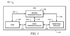
- a RMCD 100may comprise a plurality of distributed components and/or functional units such that each functional unit may communicate with another functional unit via a suitable signal conduit, for example, via one or more electrical connections, as will be disclosed herein.
- the RMCD 100may generally comprise a printed circuit board (PCB) 102 , a first microcontroller 104 , a second microcontroller 106 , a computer-on-module (COM) or system-on-module (SOM) 108 , and one or more embedded or peripheral modules 110 .
- PCBprinted circuit board
- COMcomputer-on-module
- SOMsystem-on-module
- the PCB 102may be configured to provide physical and electrical connectivity between one or more functional units, for example, between one or more microcontrollers, between one or more peripheral modules, between a microcontroller and one or more peripheral modules, etc.
- the PCB 102may generally comprise a non-conductive substrate having a plurality of conductive flow paths, tracks, traces, or the like, and thereby provides a plurality of routes for electrical signal communication.
- the PCB 102may comprise a plurality of preconfigured electrical signal flow paths (e.g., one or more conductive electrical signal flow paths etched onto the PCB 102 ) and a plurality of configurable electrical signal flow paths (e.g., one or more electronically switchable electrical signal flow paths, for example, via one or more transistors, microprocessors, etc.), as will be disclosed herein.
- a plurality of preconfigured electrical signal flow pathse.g., one or more conductive electrical signal flow paths etched onto the PCB 102
- a plurality of configurable electrical signal flow pathse.g., one or more electronically switchable electrical signal flow paths, for example, via one or more transistors, microprocessors, etc.
- the first microcontroller 104 and/or the second microcontroller 106may be a peripheral interface controller (PIC), a field programmable gate array (FPGA), or an embedded processor and may generally comprise an ALU, one or more data registers, an ADC, one or more memory devices, a plurality of input/output (I/O) ports, a matrix switch, one or more signal conditioners or adapters, any other suitable functional unit as would be appreciated by one of ordinary skill in the art upon viewing this disclosure, or combination thereof.
- the first microcontroller 104 and/or the second microcontroller 106may be configured to selectively provide one or more electrical signal flow paths, for example, via one or more I/O ports.
- the first microcontroller 104 and/or the second microcontroller 106may be configured to communicate an electrical signal to a plurality of I/O ports (e.g., a controller area network (CAN) bus, an Inter-Integrated Circuit (I 2 C) bus, a Universal Serial Bus (USB), a low pin count (LPC) bus, a Universal Asychronous Receiver/Transmitter (UART) bus, a low voltage differential signaling (LVDS) bus, etc.) and to employ any suitable signaling protocol as would be appreciated by one of ordinary skill in the art upon viewing this disclosure.
- I/O portse.g., a controller area network (CAN) bus, an Inter-Integrated Circuit (I 2 C) bus, a Universal Serial Bus (USB), a low pin count (LPC) bus, a Universal Asychronous Receiver/Transmitter (UART) bus, a low voltage differential signaling (LVDS) bus, etc.
- a plurality of I/O portse.g., a controller area network (
- the first microcontroller 104 and/or the second microcontroller 106may comprise a memory device having instructions to allow and/or to disallow one or more electrical signal flow paths (e.g., via one or more I/O ports) in response to a data signal (e.g., a device profile), as will be disclosed herein.
- a data signale.g., a device profile
- the first microcontroller 104 and the second microcontroller 106each comprise an electronic circuit configured to perform logical and/or arithmetic operations. Additionally, the first microcontroller 104 and/or the second microcontroller 106 may further comprise a memory storage device (e.g., an electrically erasable programmable read-only memory (EEPROM), an erasable programmable read-only memory (EPROM), a read-only memory (ROM), etc.) having a system basic input/output system (BIOS), a board support package (BSP), an operating system, a look-up table, a firmware, a driver, data instructions, or the like programmed onto the first microcontroller 104 and/or the second microcontroller 106 , for example, for the purpose of performing one or more operations (e.g., detecting hardware, configuring I/O ports, performing an authentication, performing a verification, etc.).
- EEPROMelectrically erasable programmable read-only memory
- EPROMerasable programmable
- the first microcontroller 104may comprise a memory having start-up instructions, such as, reading a temperature sensor, initializing general purpose input/output (GPIO) ports, and enabling power flow (e.g., to a COM, one or more peripheral devices, etc.).
- start-up instructionssuch as, reading a temperature sensor, initializing general purpose input/output (GPIO) ports, and enabling power flow (e.g., to a COM, one or more peripheral devices, etc.).
- first microcontroller 104 and the second microcontroller 106are configured to control the flow of data through the RMCD 100 and/or to coordinate the activities of one or more functional units of the RMCD 100 .
- the first microcontroller 104 and/or the second microcontroller 106may be in electrical signal communication with and/or configured to control signal communications (e.g., data transmission) between the first microcontroller 104 , the second microcontroller 106 , the COM 108 , the peripheral modules 110 , any other suitable functional units, or combinations thereof.
- the second microcontroller 106may comprise a memory having a plurality of predefined I/O port configurations for a particular device (e.g., a COM, a peripheral module, etc.) and, thereby allowing the second microcontroller 106 to configure, monitor, police, etc. electrical signal communication via the second microcontroller 106 .
- a particular devicee.g., a COM, a peripheral module, etc.
- the first microcontroller 104is in electrical signal communication with the second microcontroller 106 (e.g., via electrical connection 150 ), the COM 108 (e.g., via electrical connection 152 ), the peripheral modules 110 (e.g., via electrical connection 156 ). Additionally, the second microcontroller 106 is in electrical signal communication with the COM 108 (e.g., via electrical connection 154 ) and the peripheral modules 110 (e.g., via electrical connection 158 ).
- the RMCD 100may comprise a power management system, for example, comprising one or more voltage regulators, power distribution networks, voltage level converters, voltage rectifiers, etc. Additionally, the RMCD 100 may be supplied with electrical power via a power source, for example, via an on-board battery, an alternating current (AC) power supply, a direct current (DC) power supply, etc. For example, the RMCD 100 may be supplied power via a 12 volt wall adapter power supply.
- a power sourcefor example, via an on-board battery, an alternating current (AC) power supply, a direct current (DC) power supply, etc.
- ACalternating current
- DCdirect current
- the RMCD 100may be supplied power via a 12 volt wall adapter power supply.
- first microcontroller 104 and/or the second microcontroller 106may be configured to be removably coupled to the PCB 102 .
- the first microcontroller 104 and/or the second microcontroller 106may each be added to or removed from the PCB 102 , for example, for programming purposes, as needed.
- the first microcontroller 104 and/or the second microcontroller 106may be coupled to a carrier board or baseboard having a peripheral connection bus (e.g., a plug-and-play device, a PCB comprising a plurality of electrical pins or contacts, etc.) and may be configured to couple with the PCB 102 via mating the peripheral connection bus of the first microcontroller 104 and/or the second microcontroller 106 to a suitable peripheral connection bus receiver on the PCB 102 .
- the first microcontroller 104is a PIC24 family microcontroller.
- the second microcontroller 106is a Texas Instruments MSP430 family microcontroller.
- the first microcontroller 104 and/or the second microcontroller 106may be any other suitable microcontroller as would be appreciated by one of ordinary skill in the art upon viewing this disclosure.
- the COM 108may be configured to be removably coupled to the PCB 102 .
- the COM 108may be added to or removed from the PCB 102 , for example, for the purpose of configuring or reconfiguring the RMCD 100 for a given application.
- the COM 108may comprise a carrier board or baseboard having a peripheral connection bus (e.g., a Qseven module, an ITX, a PC-104, a COM express module, a plug-and-play device, a custom PCB comprising a plurality of electrical pins or contacts, etc.) and may be configured to couple with the PCB 102 via mating the peripheral connection bus of the COM 108 to a suitable peripheral connection bus receiver on the PCB 102 .
- a peripheral connection buse.g., a Qseven module, an ITX, a PC-104, a COM express module, a plug-and-play device, a custom PCB comprising a plurality of electrical pins or contacts, etc.
- the COM 108may generally comprise a central processing unit (CPU) or system-on-chip (SOC) (e.g., Intel Atom series, Freescale series, Texas Instruments OMAP series, etc.), a hub controller, a power management module, a memory device (e.g., a random access memory (RAM), a read only memory (ROM), a flash memory, a cache, etc.), a plurality of I/O ports (e.g., a PCIe bus, a CAN bus, an I 2 C bus, a USB, a LPC bus, a UART bus, a LVDS bus, a DisplayPort, etc.), an audio processor, a video processor, a multi-band radio module, any other suitable functional unit, or combination thereof.
- CPUcentral processing unit
- SOCsystem-on-chip
- I/O portse.g., a PCIe bus, a CAN bus, an I 2 C bus, a USB, a LPC bus, a UART bus,
- the COM 108may be configured to support and/or to execute one or more instruction sets, for example, an X86 instruction set (e.g., an x86 platform) or BIOS, an ARM instruction set (e.g., an ARM platform) or BSP, etc. Additionally, the COM 108 may be configured to support and/to execute one or more operating systems (OS), for example, a Windows-based OS, a Linux-based OS, an Android-based OS, or the like. In an embodiment, the COM 108 is an x86 platform CPU. In an alternative embodiment, the COM 108 is an ARM platform CPU. Additionally, in an embodiment, the COM 108 is integrated onto a Qseven module or board.
- OSoperating systems
- the one or more peripheral modules 110may be configured to be removably coupled to the PCB 102 .
- the one or more peripheral modules 110may be added to or removed from the PCB 102 , for example, for the purpose of configuring or reconfiguring the RMCD 100 for a given application.
- the peripheral modules 110may each comprise a carrier board or baseboard having a peripheral connection bus (e.g., a plug-and-play device, a PCB comprising a plurality of electrical pins or contacts, etc.) and may be configured to couple with the PCB 102 via mating the peripheral connection bus of the peripheral module 110 to a suitable peripheral connection bus receiver on the PCB 102 .
- a peripheral connection buse.g., a plug-and-play device, a PCB comprising a plurality of electrical pins or contacts, etc.
- the peripheral modules 110may be generally configured to provide increased functionality to the RMCD 100 .
- the peripheral modules 110may comprise a display module, for example, a liquid crystal display (LCD), a light emitting diode (LED) display, an organic light emitting diode (OLED) display, an active-matrix organic light emitting diode (AMOLED) display, a color super twisted nematic (CSTN) display, a thin film transistor (TFT) display, a thin film diode (TFD) display, and/or any other suitable type of display as would be appreciated by one of ordinary skill in the art upon viewing this disclosure.
- a display modulefor example, a liquid crystal display (LCD), a light emitting diode (LED) display, an organic light emitting diode (OLED) display, an active-matrix organic light emitting diode (AMOLED) display, a color super twisted nematic (CSTN) display, a thin film transistor (TFT) display, a thin film
- the peripheral modules 110may comprise one or more user interfaces, for example, a capacitive touchscreen, a resistive touchscreen, an inductive digitizer, a key pad, a mouse pad, a track ball, one or more buttons, any other suitable human input devices as would be appreciated by one of ordinary skill in the art upon viewing this disclosure, or combinations thereof.
- a capacitive touchscreenfor example, a capacitive touchscreen, a resistive touchscreen, an inductive digitizer, a key pad, a mouse pad, a track ball, one or more buttons, any other suitable human input devices as would be appreciated by one of ordinary skill in the art upon viewing this disclosure, or combinations thereof.
- the peripheral modules 110may comprise one or more sensors or cameras, for example, a CMOS imager module, a barcode module, a near field card reader module, a magnetic card reader module, a radio frequency identification (RFID) module, a biometric sensor module, a light detector module, a camera flash module, a global position system (GPS) module, a bedside monitor module, an accelerometer module, a gyroscope module, and/or any other suitable type of sensor or camera module as would be appreciated by one of ordinary skill in the art upon viewing this disclosure.
- the peripheral modules 110may comprise one or more audio modules, for example, a speaker or a microphone.
- the peripheral modules 110may comprise one or more communications or connectivity modules, for example, an ethernet module, a WiFi module, a radio module, a cellular radio module, an antenna, a multi-band antenna, a Bluetooth module, an infrared module, near filed communications module (NFC), and/or any other suitable type of communications or connectivity module as would be appreciated by one of ordinary skill in the art upon viewing this disclosure. Additionally or alternatively, the peripheral modules 110 may comprise one or more I/O connection modules, for example, an HDMI module, a RS-223 module, a USB module, a DVI module, a VGA module, an S-video module, a docking port interface module, and/or any other suitable type of I/O connection module.
- I/O connection modulesfor example, an HDMI module, a RS-223 module, a USB module, a DVI module, a VGA module, an S-video module, a docking port interface module, and/or any other suitable type of I/O connection module.
- the peripheral modules 110may comprise a power supply module, for example, a battery pack module. Additionally or alternatively, the peripheral modules 110 may comprise one or more military or security modules, for example, a common access card (CAC) reader module, a secure radio modem module, a selective availability GPS module, an encryption/decryption module, a SAASM/TacLink expansion module (STEM), and/or any other suitable military module.
- the peripheral modules 110may comprise a STEM module comprising a military microgram GPS receiver with an embedded antenna and a secure TacLink 3300 data modem. Additionally or alternatively, the peripheral modules 110 may comprise any other suitable type and/or configuration of peripheral modules as would be appreciated by one of ordinary skill in the art upon viewing this disclosure.
- the one or more peripheral modules 110may be configured to communicate with the first microcontroller 104 and/or the second microcontroller 106 via any suitable electrical signal protocol (e.g., a protocol defined by the Institute of Electrical and Electronics Engineers (IEEE)) as would be appreciated by one of ordinary skill in the art upon viewing this disclosure.
- any suitable electrical signal protocole.g., a protocol defined by the Institute of Electrical and Electronics Engineers (IEEE)
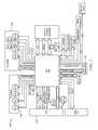
- the first microcontroller 104is a peripheral interface controller (PIC) and is integrated with the PCB 102 (e.g., shown as a main logic board (MLB)) and in electrical communication with a plurality of on-board devices and peripheral connections associated with the PCB 102 (e.g., sensors, I/O ports, etc.).
- PICperipheral interface controller
- MLBmain logic board
- the first microcontroller 104is in electrical signal communication with a plurality of connection buses (e.g., a COM connection bus 120 , an on-demand expansion module (ODEM) connection bus 122 , super I/O bus, etc.), sensors (e.g., compass, accelerometer, thermometer, etc.), I/O ports (e.g., a CAN bus, an I 2 C bus, a USB, a LPC bus, a UART bus, etc.), peripheral modules (e.g., user interface module 110 a , I/O module 110 b , etc.), and any other component or device associated with the PCB 102 .
- connection busese.g., a COM connection bus 120 , an on-demand expansion module (ODEM) connection bus 122 , super I/O bus, etc.
- sensorse.g., compass, accelerometer, thermometer, etc.
- I/O portse.g., a CAN bus, an I 2 C bus, a
- the second microcontroller 106is coupled to a carrier board having a peripheral connection bus (e.g., a plug-and-play device, a custom PCB comprising a plurality of electrical pins or contacts, etc.) and is coupled with the PCB 102 (e.g., MLB) via the peripheral connection bus receiver (e.g., the ODEM connection bus 122 ).
- the COM 108may comprise a carrier board having a peripheral connection bus (e.g., a Qseven module, a plug-and-play device, a PCB comprising a plurality of electrical pins or contacts, etc.) and is coupled with the PCB 102 via the peripheral connection bus receiver (e.g., connection bus 120 ).
- the PCB 102is coupled to a plurality of peripheral modules.
- the PCB 102is coupled to a user interface (UI) module 110 a having a plurality of buttons (e.g., a reset button, a power button, etc.) and I/O ports (e.g., a power terminal, a USB port, a headphone jack, etc.) via a connection bus 126 , a I/O module 110 b having a plurality of buttons and a I/O ports (e.g., a USB port, an HDMI port, a memory port, etc.), a radio module 110 d (e.g., a multi-radio card), and a memory module 110 c (e.g., a Mini-SATA).
- UIuser interface
- I/O portse.g., a power terminal, a USB port, a headphone jack, etc.
- a radio module 110 de.g., a multi-radio card
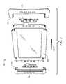
- the RMCD 100may be disposed within a housing or an enclosure 500 which may be configured to protect the RMCD 100 .
- the housing 500may provide a means for transporting the RMCD 100 and/or for integrating the RMCD 100 with other structures or devices.
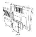
- the housing 500may be configured to be mounted on and/or integrated with, for example, a wall mount, a flush mount, a desktop mount, a stand, a mobile dock, a docking station (e.g., via a docking connector 514 ), a bumper guard 512 , or the like.
- the housingmay be made of two or more operably connected components (e.g., a front case 502 , a mid-frame 504 , and a back case 506 ).
- RMCD 100may be coupled to the mid-frame 504 (e.g., via the PCB 102 ) and enclosed by the front case 502 and the back case 506 .
- the housingmay comprise any suitable enclosure structure as will be appreciated by one of ordinary skill in the art with the aid of this disclosure.
- the housingmay comprise one or more mounting surfaces, recesses, and/or openings, for example, for the purpose of mounting one or more components of the RMCD 100 (e.g., the PCB 102 , one or more peripherals 110 , etc.).
- the housing 500may be configured to mount or support a user interface module 110 a and an I/O module 110 b .
- the housing 500may be configured to integrate one or more add-on or expansion modules (e.g., a battery pack 518 , a heat spreader 510 , etc.).
- an expansion module 516may be integrated with the housing 500 and RMCD 100 via an expansion connector 508 .
- the housingmay be made of conventional materials and methods as would be appreciated by one of ordinary skill in the art.
- the RMCD 100may further comprise one or more thermal provisions.
- the RMCD 100may comprise one or more passive thermal provision (e.g., a heat spreader, a heat sink, a heat pipe, a vent, etc.) and/or one or more active thermal provisions (e.g., a fan, a forced air system, a hydraulic system, a cryogenic cooling system, etc.).
- the thermal provisionsmay extend the operating temperature range (e.g., allowing a higher operating temperature and/or a lower operating temperature) beyond that which is achievable without such thermal provisions.
- the RMCD 100may comprise a forced air system (e.g., an electric fan) in electrical signal communication with the first microcontroller 104 and/or the second microcontroller 106 and may be configured to be controlled and/or operated by the first microcontroller 104 and/or the second microcontroller 106 .
- a forced air systeme.g., an electric fan
- a method of configuring a computing device utilizing a RMCDis disclosed herein.
- a computing device configuring method 300may generally comprise the steps of providing a PCB (e.g., the MLB of FIG. 3 ) comprising a first microcontroller (e.g., the PIC of MLB of FIG. 3 ) and a second microcontroller (e.g., the ODEM module of FIG. 3 ) 302 , coupling a COM (e.g., the COM of FIG. 3 ) to the PCB 304 , interrogating the COM 306 , coupling one or more peripheral modules (e.g., UI module and I/O module of FIG. 3 ) to the PCB 308 , interrogating the peripheral modules 310 , configuring the second microcontroller 312 , and communicating an electrical signal between the COM and the peripheral modules via the second microcontroller 314 .
- a PCBe.g., the MLB of FIG. 3
- a first microcontroller
- the computing device configuring method 300may further comprise decoupling the COM from the PCB 102 , coupling a second COM to the PCB 102 , interrogating the second COM, configuring the second microcontroller 106 , and communicating an electrical signal between the second COM and the peripheral modules 110 . Additionally or alternative, the computing device configuring method 300 may further comprise reconfiguring the peripheral modules 110 , interrogating the peripheral modules 110 , configuring the second microcontroller 106 , and communicating an electrical signal between the COM and the peripheral modules 110 . Additionally or alternatively, the computing device configuring method 300 may further comprise providing a docking station, interrogating the docking station, configuring the second microcontroller 106 , and communicating an electrical signal between the COM and the docking station.
- the PCB 102may be provided comprising the first microcontroller 104 and the second microcontroller 106 .
- the PCB 102may be coupled to and/or disposed within the housing 500 , for example, the PCB 102 is mounted to a mid-frame 504 within the housing 500 , as shown in FIG. 4 .
- the first microcontroller 104 and/or the second microcontroller 106may be installed onto the PCB 102 , for example, following mounting the PCB 102 to the housing 500 .
- the second microcontroller 106may be installed into a suitable receiver port (e.g., a peripheral connection bus) on the PCB 102 .
- the first microcontroller 104 and/or the second microcontroller 106may be hard-wired (e.g., soldered) to a plurality of electrical traces on the PCB 102 .
- the first microcontroller 104 and/or the second microcontroller 106may be programmed or reprogrammed with data and/or device setting configurations, for example, to provide a default device configuration and/or logical operations.
- one or more I/O portsmay be configured, a firmware may be installed, a driver may be installed, a BIOS may be configured, and/or any other suitable configuration operation may be performed as would be appreciated by one of ordinary skill in the art upon viewing this disclosure.
- a COM 108may be provided and installed or coupled onto the PCB 102 .
- the COM 108may be determined and/or configured for a desired application, for example, the COM 108 may comprise a preset operating system, CPU, chipset, etc.
- the COM 108comprises a carrier board (e.g., a PCB have a plurality of electrical contacts)
- the COM 108may be installed into a suitable receiver port (e.g., a peripheral connection bus) on the PCB 102 , thereby providing a route of electrical signal communication between the COM 108 and the first microcontroller 104 and the COM 108 and the second microcontroller 106 .
- the first microcontroller 104 and/or the second microcontroller 106may interrogate the COM 108 , for example, via the I/O ports (e.g., I 2 C, LPC, UART, etc.) and employing any suitable protocol and/or method as would be appreciated by one of ordinary skill in the art upon viewing this disclosure.
- the I/O portse.g., I 2 C, LPC, UART, etc.
- the first microcontroller 104 and/or the second microcontroller 106may employ a hardware detection protocol (e.g., a plug-and-play protocol) to detect the presence of the COM 108 , for example, via an OS, a firmware, a driver, or data instructions programmed onto the first microcontroller 104 and/or the second microcontroller 106 .
- a hardware detection protocole.g., a plug-and-play protocol
- the first microcontroller 104 and/or the second microcontroller 106may generate or determine a COM profile.
- the COM profilemay generally comprise device information, device configuration parameters, and/or device settings, etc. based on the detected COM 108 .
- the COM profilemay comprise CPU information (e.g., Intel Atom E780T, Freescale iMX6, etc.), chip set information, clock speed information, OS information, manufacturing information, security key encryption, or any other suitable information for distinguishing and/or describing a COM as would be appreciated by one of ordinary skill in the art upon viewing this disclosure.
- CPU informatione.g., Intel Atom E780T, Freescale iMX6, etc.
- chip set informatione.g., clock speed information, OS information, manufacturing information, security key encryption, or any other suitable information for distinguishing and/or describing a COM as would be appreciated by one of ordinary skill in the art upon viewing this disclosure.
- one or more peripheral modules 110may be provided and installed or coupled onto the PCB 102 .
- the peripheral modules 110may be determined and/or configured for a desired application.
- the peripheral modules 110may comprise one or more user interface modules (e.g., a display, a keypad, a touchscreen, etc.), one or more I/O modules (e.g., a HDMI module, a USB module, a VGA module, etc.), and/or any other suitable module as would be appreciated by one of ordinary skill in the art upon viewing this disclosure.
- the peripheral modules 110may be installed into a suitable receiver port (e.g., a peripheral connection bus) on the PCB 102 , thereby providing a route of electrical signal communication between the peripheral modules 110 and the first microcontroller 104 and the peripheral modules 110 and the second microcontroller 106 .
- a suitable receiver porte.g., a peripheral connection bus
- the first microcontroller 104 and/or the second microcontroller 106may interrogate each of the peripheral modules 110 .
- the first microcontroller 104 and/or the second microcontroller 106may employ a hardware detection protocol (e.g., a plug-and-play protocol) to detect the presence of each peripheral module 110 , for example, via an OS, a firmware, a driver, or data instructions programmed onto the first microcontroller 104 and/or the second microcontroller 106 .
- a hardware detection protocole.g., a plug-and-play protocol
- the first microcontroller 104 and/or the second microcontroller 106may generate or determine a peripheral module profile.
- the peripheral module profilemay generally comprise device information, device configuration parameters, and/or device settings, etc. based on the detected peripheral modules 110 .
- the second microcontroller 106may provide one or more electrical signal flow paths in response to the COM profile and/or the peripheral module profile.
- one or more I/O ports of the second microcontroller 106may be configured and/or reconfigured dependent on the COM 108 and/or the peripheral modules 110 coupled to the PCB 102 (e.g., based on the COM profile and/or the peripheral module profile), thereby allowing and/or disallowing one or more electrical signal flow paths between the COM 108 and the peripheral modules 110 via the second microcontroller 106 .
- the second microcontroller 106comprises a memory having a look-up table relating a plurality of predefined I/O port configurations with a particular device (e.g., a COM, a peripheral module, etc.). For example, following detecting a device coupled to the PCB 102 , the second microcontroller 106 may determine the profile of the device (e.g., via the COM profile, the peripheral module profile, etc.) and may employ a predefined I/O port configuration associated with the detected device, thereby routing an electrical signal flow path and enabling electrical signal communication to the device via the second microcontroller 106 .
- a particular devicee.g., a COM, a peripheral module, etc.
- the second microcontroller 106may determine the profile of the device (e.g., via the COM profile, the peripheral module profile, etc.) and may employ a predefined I/O port configuration associated with the detected device, thereby routing an electrical signal flow path and enabling electrical signal communication to the device via the second microcontrol
- the second microcontroller 106may comprise and/or is coupled to a plurality of electronically switchable gates (e.g., a matrix switch, a gate array, etc.) and implement predefined switch configurations associated with the detected device, thereby routing an electrical signal flow path and enabling electrical signal communication to the device via the second microcontroller 106 . Additionally, the second microcontroller 106 may determine (e.g., via the COM profile, the peripheral module profile, etc.) and allow the appropriate protocols and/or signaling to be performed based on the detected device. Alternatively, any suitable passive or active methods or techniques may be employed to configure the I/O ports of the second microcontroller 106 in response to a particular device, as would be appreciated by one of ordinary skill in the art upon viewing this disclosure.
- a plurality of electronically switchable gatese.g., a matrix switch, a gate array, etc.
- the second microcontroller 106may determine (e.g., via the COM profile, the peripheral module profile, etc.) and allow the appropriate protocols and
- the COM 108may communicate an electrical signal (e.g., a data signal) to/from the peripheral modules 110 via the electrical signal flow paths enabled by the second microcontroller 106 .
- the peripheral modules 110may comprise a display (e.g., a LCD screen, a LED screen, etc.) and the COM 108 may display graphical data on the display.
- the peripheral modules 110may comprise a plurality of I/O port modules (e.g., a USB module, an HDMI module, etc.) and the COM 108 may transfer data to/from the I/O port modules via the electrical signal flow paths enabled by the second microcontroller 106 .
- the peripheral modules 110may comprise a user interface module (e.g., a keypad, a touch screen, etc.) and the COM 108 may receive commands from a user via the user interface module via the electrical signal flow paths enabled by the second microcontroller 106 .
- the peripheral modules 110may comprise a sensor module (e.g., a camera, a RFID module, etc.) and the COM 108 may receiver sensor data from the sensor module via the electrical signal flow paths enabled by the second microcontroller 106 .
- the peripheral modules 110may comprise a communications module (e.g., a WiFi module, a cellular radio module, etc.) and the COM 108 may transmit and receive data via the communications module via the electrical signal flow paths enabled by the second microcontroller 106 .
- the COM 108may employ or communicate with any other suitable peripheral module 110 via the electrical signal flow paths enabled by the second microcontroller 106 , as would be appreciated by one of ordinary skill in the art upon viewing this disclosure.
- the RMCD 100may be reconfigured and the COM 108 may be replaced and/or removed from the PCB 102 .
- the COM 108may be decoupled from the PCB 102 , for example, via removing the COM 108 from a peripheral connection bus on the PCB 102 .
- a second COMmay be provided and installed onto or coupled to the PCB 102 , for example, using the same connection and footprint as the COM 108 .
- the second COMmay be determined and/or configured (e.g., a preset operating system, CPU, chipset, etc.) for a desired application.
- the second COMis different from the COM 108 (e.g., a change from a x86 COM platform to an ARM COM platform).
- the second COMis a new or updated version of the COM 108 (e.g., an x86 or ARM COM platform update, for example, an updated CPU, chip set, etc.).
- the second COMmay be installed into a suitable receiver port (e.g., a peripheral connection bus) on the PCB 102 .
- the first microcontroller 104 and/or the second microcontroller 106may interrogate the second COM to generate or determine a COM profile based on the second COM, similar to previously disclosed.
- one or more I/O ports of the second microcontroller 106may be configured and/or reconfigured dependent on the second COM coupled to the PCB 102 (e.g., based on the COM profile), thereby allowing and/or disallowing one or more electrical signal flow paths between the second COM and the peripheral modules 100 via the second microcontroller 106 .
- the second COMmay communicate an electrical signal (e.g., a data signal) to/from the peripheral modules 110 via the electrical signal flow paths enabled by the second microcontroller 106 .
- an electrical signale.g., a data signal
- the RMCD 100may be reconfigured and one or more peripheral modules may be replaced and/or removed from the PCB 102 .
- one or more peripheral modulese.g., the UI module 110 a and/or the I/O module 110 b of FIG. 3
- one or more additional and/or different peripheral modulesmay be provided and installed or coupled onto the PCB 102 .
- the peripheral modulesmay be determined and/or configured for a desired application.
- the first microcontroller 104 and/or the second microcontroller 106may interrogate the peripheral modules to generate or determine a peripheral module profile based on the peripheral modules coupled to the PCB 102 , similar to previously disclosed. Additionally, one or more I/O ports of the second microcontroller 106 may be configured and/or reconfigured dependent on the peripheral modules coupled to the PCB 102 (e.g., based on the peripheral module profile), thereby allowing and/or disallowing one or more electrical signal flow paths between the COM 108 and the peripheral modules via the second microcontroller 106 .
- the COM 108may communicate an electrical signal (e.g., a data signal) to/from the peripheral modules via the electrical signal flow paths enabled by the second microcontroller 106 .
- an electrical signale.g., a data signal
- the RMCD 100may be coupled to or integrated with a docking station 200 .
- the docking station 200may comprise a third microcontroller 112 in electrical signal communication with one or more dock peripheral modules 114 (e.g., one or more user interface modules, one or more I/O modules, etc.), for example, via electrical connection 162 .
- the RMCD 100may be physically and/or electrically coupled to the docking station 200 , for example, the housing of the RMCD 100 may be supported by the docking station 200 and the RMCD 100 may be in electrical signal communication with the docking station 200 via an electrical connection 160 .
- the first microcontroller 104 and/or the second microcontroller 106may interrogate the docking station 200 (e.g., the third microcontroller 112 and/or the dock peripherals 114 ) to generate or determine a docking station profile based on the docking station 200 , similar to previously disclosed.
- the docking station 200e.g., the third microcontroller 112 and/or the dock peripherals 114 .
- one or more I/O ports of the second microcontroller 106may be configured and/or reconfigured dependent on the docking station 200 coupled to the RMCD 100 (e.g., based on the docking station profile), thereby allowing and/or disallowing one or more electrical signal flow paths between the COM 108 and the docking station 200 (e.g., the third microcontroller 112 , the dock peripherals 114 , etc.) via the second microcontroller 106 .
- the COM 108may communicate an electrical signal (e.g., a data signal) to/from the docking station 200 via the electrical signal flow paths enabled by the second microcontroller 106 .
- the docking station 200may comprise the third microcontroller 112 in electrical signal communication with a docking station COM 109 , a fourth microcontroller 116 , and one or more dock peripheral modules 114 (e.g., one or more user interface modules, one or more I/O modules, etc.).
- the fourth microcontrollermay be in electrical signal communication with the docking station COM 109 and the dock peripheral modules 114 .
- the RMCD 100may be physically and/or electrically coupled to the docking station 200 , for example, the housing of the RMCD 100 may be supported by the docking station 200 and the RMCD 100 may be in electrical signal communication with the docking station 200 via a docking module 110 e .
- the first microcontroller 104 and/or the second microcontroller 106may interrogate the docking station 200 (e.g., the third microcontroller 112 , the fourth microcontroller 116 , the docking station COM 109 , and/or the dock peripherals 114 ) to generate or determine a docking station profile based on the docking station 200 , similar to previously disclosed.
- the docking station 200e.g., the third microcontroller 112 , the fourth microcontroller 116 , the docking station COM 109 , and/or the dock peripherals 114 .
- the second microcontroller 106comprises a matrix switch and may configure and/or reconfigure one or more electrical signal flow paths (e.g., via switching one or more electronically switchable gates), thereby allowing and/or disallowing one or more electrical signal flow paths between the COM 108 and the docking station 200 (e.g., the third microcontroller 112 , the fourth microcontroller 116 , the docking station COM 109 , the dock peripherals 114 , etc.) via the second microcontroller 106 .
- the docking station 200e.g., the third microcontroller 112 , the fourth microcontroller 116 , the docking station COM 109 , the dock peripherals 114 , etc.
- one or more I/O ports of the second microcontroller 106may be configured and/or reconfigured one or more electrical signal flow paths dependent on the docking station 200 coupled to the RMCD 100 (e.g., based on the docking station profile), thereby allowing and/or disallowing one or more electrical signal flow paths between the COM 108 and the docking station 200 (e.g., the third microcontroller 112 , the fourth microcontroller 116 , the docking station COM 109 , the dock peripherals 114 , etc.) via the second microcontroller 106 .
- the COM 108may communicate an electrical signal (e.g., a data signal) to/from the docking station 200 via the electrical signal flow paths enabled by the second microcontroller 106 .
- an electrical signale.g., a data signal
- a computing devicesuch as the RMCD 100 , a computing system comprising a RMCD, such as RMCD 100 , a computing device configuring method employing such a computing device, such as RMCD 100 , or combinations thereof may be advantageously employed to allow manufacturer, a reseller, or an end-user to configure and/or reconfigure the RMCD for one or more applications, as needed.
- a RMCDallows a user to configure the RMCD for a first application (e.g., comprising a first set of a COM, peripheral modules, etc.) and then reconfigure the RMCD for one or more subsequent applications (e.g., comprising a second set of a COM, peripheral modules, etc.).
- Conventional computing devicemay be limited and/or unable to support a broad range of applications, COMs, and/or peripheral modules.
- the RMDCmay be suitably employed in a variety of applications and may support a variety of COMs and peripheral modules using a common platform. Additionally, such an RMDC may reduce cost, which may be typically unachievable for similar low volume custom devices.
- a first embodimentwhich is a configurable computing device comprising:
- a second embodimentwhich is the configurable computing device of the first embodiment, wherein the second microcontroller comprises a plurality of programmable input/output ports.
- a third embodimentwhich is the configurable computing device of any one of the first embodiment through the second embodiment, wherein the second microcontroller is in electrical signal communication with a plurality of electronic switches.
- a fourth embodimentwhich is the configurable computing device of any one of the first embodiment through the third embodiment, wherein the COM is an x86 platform or an ARM platform.
- a fifth embodimentwhich is the configurable computing device of any one of the first embodiment through the fourth embodiment, wherein the peripheral modules comprises a user interface (UI) module.
- UIuser interface
- a sixth embodimentwhich is the configurable computing device of any one of the first embodiment through the fifth embodiment, wherein the peripheral modules comprises an input output (IO) module.
- IOinput output
- a seventh embodimentwhich is the configurable computing device of any one of the first embodiment through the sixth embodiment, wherein the peripheral modules comprises a display screen.
- An eighth embodimentwhich is the configurable computing device of any one of the first embodiment through the seventh embodiment, wherein the peripheral modules comprise a touch screen.
- a ninth embodimentwhich is the configurable computing device of any one of the first embodiment through the eighth embodiment, wherein the device is configured to be hand-held.
- a tenth embodimentwhich is the configurable computing device of any one of the first embodiment through the ninth embodiment, wherein the peripheral module comprises a docking module.
- An eleventh embodimentwhich is the configurable computing device of any one of the first embodiment through the tenth embodiment, further comprising one or more thermal provisions.
- a twelfth embodimentwhich is a computing device configuring method comprising the steps of:
- a thirteenth embodimentwhich is the computing device configuring method of the twelfth embodiment, wherein interrogating the COM is performed by the first microcontroller.
- a fourteenth embodimentwhich is the computing device configuring method of any one of the twelfth embodiment through the thirteenth embodiment, wherein interrogating the one or more peripheral modules is performed by the first microcontroller.
- a fifteenth embodimentwhich is the computing device configuring method of any one of the twelfth embodiment through the fourteenth embodiment, further comprising the steps of:
- a sixteenth embodimentwhich is the computing device configuring method of any one of the twelfth embodiment through the fifteenth embodiment, further comprising the steps of:
- a seventeenth embodimentwhich is the computing device configuring method of any one of the twelfth embodiment through the sixteenth embodiment, further comprising the steps of:
- An eighteenth embodimentwhich is the computing device configuring method of any one of the twelfth embodiment through the sixteenth embodiment, further comprising the steps of:
- a nineteenth embodimentwhich is a mobile computing device comprising:
- a twentieth embodimentwhich is the mobile computing device of the nineteenth embodiment, further comprising one or more thermal provision.
- RRl+k*(Ru ⁇ Rl)
- kis a variable ranging from 1 percent to 100 percent with a 1 percent increment, i.e., k is 1 percent, 2 percent, 3 percent, 4 percent, 5 percent, . . . 50 percent, 51 percent, 52 percent, . . . , 95 percent, 96 percent, 97 percent, 98 percent, 99 percent, or 100 percent.
- any numerical range defined by two R numbers as defined in the aboveis also specifically disclosed.
Landscapes
- Engineering & Computer Science (AREA)
- Theoretical Computer Science (AREA)
- General Engineering & Computer Science (AREA)
- Physics & Mathematics (AREA)
- General Physics & Mathematics (AREA)
- Computer Hardware Design (AREA)
- Human Computer Interaction (AREA)
- Manufacturing & Machinery (AREA)
- Microelectronics & Electronic Packaging (AREA)
- Stored Programmes (AREA)
- Power Sources (AREA)
- Two-Way Televisions, Distribution Of Moving Picture Or The Like (AREA)
- User Interface Of Digital Computer (AREA)
Abstract
Description
- a housing;
- a printed circuit board (PCB) disposed within the housing;
- a first microcontroller and a second microcontroller each coupled to the PCB, wherein the first microcontroller and the second microcontroller are in electrical signal communication with each other;
- a computer-on-module (COM) coupled to the PCB, wherein the COM is in electrical signal communication with the first microcontroller and the second microcontroller; and
- one or more peripheral modules coupled to the PCB,
- wherein, the peripheral modules are each in electrical signal communication with the first microcontroller; and
- wherein, the peripheral modules are each in electrical signal communication with the COM via the second microcontroller.
- providing a printed circuit board (PCB) comprising a first microcontroller and a second microcontroller, wherein the first microcontroller and the second microcontroller are in electrical signal communication with each other;
- installing a computer-on-module (COM) to the PCB, wherein the COM is electrically coupled to the PCB;
- interrogating the COM, thereby determining a COM profile;
- installing one or more peripheral modules to the PCB, wherein the peripherals are each electrically coupled to the PCB;
- interrogating the peripheral modules, thereby determining a peripheral module profile;
- configuring the second microcontroller,
- wherein, the second microcontroller is configured dependent on the COM profile and the peripheral module profile and provides one or more electrical signal flow paths between the COM and the peripheral modules; and
- communicating an electrical signal between the COM and the peripheral modules via the second microcontroller.
- removing the COM from the PCB;
- installing a second COM to the PCB;
- interrogating the second COM; and
- configuring the second microcontroller, wherein the second microcontroller provides one or more electrical signal flow path between the second COM and the one or more peripheral modules;
- communicating an electrical signal between the second COM and the one or more peripheral modules via the second microcontroller.
- reconfiguring the peripheral modules coupled to the PCB;
- interrogating the reconfigured peripheral modules;
- installing the second microcontroller, wherein the second microcontroller provides one or more electrical signal flow path between the COM and the peripheral modules; and
- communicating an electrical signal between the COM and the peripheral modules via the second microcontroller.
- providing a docking station comprising one or more dock microcontrollers in electrical signal communication with one or more dock peripheral modules, wherein the peripheral modules are in electrical signal communication with the dock microcontrollers;
- interrogating the docking station;
- configuring the second microcontroller, wherein the second microcontroller provides one or more electrical signal flow path between the COM and the dock peripheral modules; and
- communicating an electrical signal between the COM and the dock peripheral modules via the second microcontroller.
- providing a docking station comprising one or more dock microcontrollers in electrical signal communication with one or more dock peripheral modules, wherein the peripheral modules are in electrical signal communication with the dock microcontrollers;
- interrogating the docking station;
- configuring the second microcontroller, wherein the second microcontroller provides one or more electrical signal flow path between the COM and the dock station COM; and
- communicating an electrical signal between the COM and the docking station COM via the second microcontroller.
- a housing comprising a front case, a mid-frame, and a back case, wherein the front case and the back case are configured to combine and enclose the mid-frame;
- a printed circuit board (PCB) coupled to the mid-frame;
- a first microcontroller and a second microcontroller each coupled to the PCB, wherein the first microcontroller and the second microcontroller are in electrical signal communication with each other;
- a computer-on-module (COM) coupled to the PCB, wherein the COM is in electrical signal communication with the first microcontroller and the second microcontroller; and
- one or more peripheral modules coupled to the PCB,
- wherein the peripheral modules are each in electrical signal communication with the first microcontroller;
- wherein the peripheral modules are each in electrical signal communication with the COM via the second microcontroller; and
- wherein the peripheral modules comprises a display, one or more input/output (I/O) ports, a dock module, and one or more user interfaces.
Claims (9)
Priority Applications (9)
| Application Number | Priority Date | Filing Date | Title |
|---|---|---|---|
| US13/794,190US8751710B2 (en) | 2012-05-08 | 2013-03-11 | Reconfigurable modular computing device |
| AU2013259973AAU2013259973A1 (en) | 2012-05-08 | 2013-04-24 | Reconfigurable modular computing device |
| PCT/US2013/038028WO2013169487A1 (en) | 2012-05-08 | 2013-04-24 | Reconfigurable modular computing device |
| KR20147033693AKR20150008434A (en) | 2012-05-08 | 2013-04-24 | Reconfigurable modular computing device |
| CA2873581ACA2873581A1 (en) | 2012-05-08 | 2013-04-24 | Reconfigurable modular computing device |
| EP13788150.4AEP2856277A4 (en) | 2012-05-08 | 2013-04-24 | Reconfigurable modular computing device |
| US14/263,742US8924609B2 (en) | 2012-05-08 | 2014-04-28 | Reconfigurable modular computing device |
| US14/547,594US9213664B2 (en) | 2012-05-08 | 2014-11-19 | Reconfigurable modular computing device |
| US14/955,824US20160085710A1 (en) | 2012-05-08 | 2015-12-01 | Reconfigurable Modular Computing Device |
Applications Claiming Priority (4)
| Application Number | Priority Date | Filing Date | Title |
|---|---|---|---|
| US201261644243P | 2012-05-08 | 2012-05-08 | |
| US201261711878P | 2012-10-10 | 2012-10-10 | |
| US201361774916P | 2013-03-08 | 2013-03-08 | |
| US13/794,190US8751710B2 (en) | 2012-05-08 | 2013-03-11 | Reconfigurable modular computing device |
Related Child Applications (1)
| Application Number | Title | Priority Date | Filing Date |
|---|---|---|---|
| US14/263,742ContinuationUS8924609B2 (en) | 2012-05-08 | 2014-04-28 | Reconfigurable modular computing device |
Publications (2)
| Publication Number | Publication Date |
|---|---|
| US20130301202A1 US20130301202A1 (en) | 2013-11-14 |
| US8751710B2true US8751710B2 (en) | 2014-06-10 |
Family
ID=49548429
Family Applications (4)
| Application Number | Title | Priority Date | Filing Date |
|---|---|---|---|
| US13/794,190Active - ReinstatedUS8751710B2 (en) | 2012-05-08 | 2013-03-11 | Reconfigurable modular computing device |
| US14/263,742Expired - Fee RelatedUS8924609B2 (en) | 2012-05-08 | 2014-04-28 | Reconfigurable modular computing device |
| US14/547,594Expired - Fee RelatedUS9213664B2 (en) | 2012-05-08 | 2014-11-19 | Reconfigurable modular computing device |
| US14/955,824AbandonedUS20160085710A1 (en) | 2012-05-08 | 2015-12-01 | Reconfigurable Modular Computing Device |
Family Applications After (3)
| Application Number | Title | Priority Date | Filing Date |
|---|---|---|---|
| US14/263,742Expired - Fee RelatedUS8924609B2 (en) | 2012-05-08 | 2014-04-28 | Reconfigurable modular computing device |
| US14/547,594Expired - Fee RelatedUS9213664B2 (en) | 2012-05-08 | 2014-11-19 | Reconfigurable modular computing device |
| US14/955,824AbandonedUS20160085710A1 (en) | 2012-05-08 | 2015-12-01 | Reconfigurable Modular Computing Device |
Country Status (6)
| Country | Link |
|---|---|
| US (4) | US8751710B2 (en) |
| EP (1) | EP2856277A4 (en) |
| KR (1) | KR20150008434A (en) |
| AU (1) | AU2013259973A1 (en) |
| CA (1) | CA2873581A1 (en) |
| WO (1) | WO2013169487A1 (en) |
Cited By (4)
| Publication number | Priority date | Publication date | Assignee | Title |
|---|---|---|---|---|
| US20140281718A1 (en)* | 2013-03-15 | 2014-09-18 | Portwell Inc. | Computer-on-module debug card assembly and a control system thereof |
| US9213664B2 (en) | 2012-05-08 | 2015-12-15 | Entegra Technologies, Inc. | Reconfigurable modular computing device |
| US20170361869A1 (en)* | 2016-06-17 | 2017-12-21 | Steering Solutions Ip Holding Corporation | Electrical power steering with two controllers and closed-loop integral action |
| US10848093B2 (en) | 2018-08-30 | 2020-11-24 | Steering Solutions Ip Holding Corporation | Electrical power steering with two controllers using uniform steering angle control |
Families Citing this family (21)
| Publication number | Priority date | Publication date | Assignee | Title |
|---|---|---|---|---|
| US9867125B2 (en) | 2014-04-07 | 2018-01-09 | Google Llc | Systems for enabling modular mobile electronic devices |
| US9929778B2 (en) | 2014-04-07 | 2018-03-27 | Google Llc | Systems for enabling chassis-coupled modular mobile electronic devices |
| US9501442B2 (en)* | 2014-04-30 | 2016-11-22 | Freescale Semiconductor, Inc. | Configurable peripheral componenent interconnect express (PCIe) controller |
| US10440849B2 (en) | 2015-06-19 | 2019-10-08 | Hewlett Packard Enterprise Development Lp | First socket nested in a second socket |
| CN105137874B (en)* | 2015-08-24 | 2017-12-05 | 宋张波 | A kind of automation control system and method |
| US10261931B2 (en)* | 2015-09-22 | 2019-04-16 | Ovh | Modular backplane |
| WO2017063319A2 (en)* | 2015-10-14 | 2017-04-20 | 南京洛普科技有限公司 | Multi-layer magnetic attaching, front-maintenance type led display having small dot pitch |
| US10084896B1 (en) | 2015-11-05 | 2018-09-25 | Google Llc | Modular electronic devices |
| US10209817B1 (en) | 2015-11-05 | 2019-02-19 | Google Llc | Modular electronic devices |
| ITUB20155775A1 (en)* | 2015-11-20 | 2017-05-20 | Inno Tech S R L S | QUICK PROTOTYPING SYSTEM |
| US11455011B2 (en) | 2016-10-13 | 2022-09-27 | Microsoft Technology Licensing, Llc | Modular computing device with common AC power |
| US10345876B2 (en) | 2016-10-13 | 2019-07-09 | Microsoft Technology Licensing, Llc | Computing device with removable power module |
| TWI678624B (en)* | 2018-05-31 | 2019-12-01 | 艾訊股份有限公司 | Modularized computer system and computing core board thereof |
| US10795407B2 (en)* | 2018-10-19 | 2020-10-06 | Rakuten Kobo Inc. | Electronic reading device with a mid-frame structure |
| US10789188B1 (en)* | 2019-02-08 | 2020-09-29 | Facebook, Inc. | Systems and methods for providing semi-custom printed circuit boards based on standard interconnections |
| CN110245100A (en)* | 2019-06-10 | 2019-09-17 | 英业达科技有限公司 | The control method of the serial port information of server host |
| DE102020104585A1 (en) | 2020-02-21 | 2021-08-26 | Heitec Ag | Computer system and method for operating a computer system |
| US11953518B2 (en)* | 2020-12-30 | 2024-04-09 | Star Technologies, Inc. | Switching matrix system and operating method thereof for semiconductor characteristic measurement |
| US20240214188A1 (en)* | 2021-05-07 | 2024-06-27 | Panasonic Intellectual Property Management Co., Ltd. | Information processing method, device, and recording medium |
| CN114063717A (en)* | 2021-11-09 | 2022-02-18 | 江苏新安电器股份有限公司 | Tool management manipulator capable of being cut out in system |
| US11785285B1 (en) | 2022-05-20 | 2023-10-10 | Lenbrook Industries Limited | Audio video receiver (AVR) architecture |
Citations (139)
| Publication number | Priority date | Publication date | Assignee | Title |
|---|---|---|---|---|
| US5559675A (en) | 1995-03-28 | 1996-09-24 | Twinhead International Corp. | Computer CPU heat dissipating and protecting device |
| DE29712774U1 (en) | 1997-07-18 | 1997-09-25 | Twinhead International Corp., Hsin Tein | Control of a CPU fan |
| US5753982A (en) | 1996-06-03 | 1998-05-19 | Twinhead International Corp. | Apparatus for supplying power to a peripheral device from computer system |
| US5852743A (en) | 1996-07-12 | 1998-12-22 | Twinhead International Corp. | Method and apparatus for connecting a plug-and-play peripheral device to a computer |
| US5877628A (en) | 1997-10-17 | 1999-03-02 | Twinhead International Corp. | Warning device for detecting RTC electrical cell |
| DE19731013A1 (en) | 1997-07-18 | 1999-03-04 | Twinhead International Corp | Process for intelligently controlling LCD backlight of notebook computer and device of it |
| US5889513A (en) | 1997-10-21 | 1999-03-30 | Twinhead International Corp. | Display device for detecting working load of a CPU |
| US5905365A (en) | 1997-10-28 | 1999-05-18 | Twinhead International Corp. | Real time-clock power supply device |
| US5962936A (en) | 1997-10-21 | 1999-10-05 | Twinhead International Corp. | Power supply device for LCD backlight converter |
| TW384464B (en) | 1998-08-19 | 2000-03-11 | Twinhead Int Corp | Method for controlling brightness of computer screens |
| US6049193A (en) | 1998-12-23 | 2000-04-11 | Twinhead International Corp. | Method and device for executing a battery auto-learning |
| TW388177B (en) | 1998-11-16 | 2000-04-21 | Twinhead Int Corp | Photographing method for video system |
| TW389854B (en) | 1998-08-21 | 2000-05-11 | Twinhead Int Corp | Method and device for automatically executing battery learning mode |
| US6069448A (en) | 1997-10-16 | 2000-05-30 | Twinhead International Corp. | LCD backlight converter having a temperature compensating means for regulating brightness |
| US6082623A (en) | 1999-03-04 | 2000-07-04 | Twinhead International Corp. | Cooling system and method for a portable computer |
| US6101087A (en) | 1997-06-19 | 2000-08-08 | Xplore Technologies, Inc. | Portable pen-based computer and auxiliary unit for use with a vehicular docking station |
| US6106566A (en)* | 1998-01-29 | 2000-08-22 | Micron Electronics, Inc. | Upgradable electronic module and system using same |
| TW403866B (en) | 1998-11-17 | 2000-09-01 | Twinhead Int Corp | A system performance switching device applied on portable electronics |
| TW411651B (en) | 1998-08-28 | 2000-11-11 | Twinhead Int Corp | An intelligent battery system |
| TW413750B (en) | 1998-12-01 | 2000-12-01 | Twinhead Int Corp | Uninterrupted Power Supply device applied to LCD monitor |
| TW416206B (en) | 1999-04-13 | 2000-12-21 | Twinhead Int Corp | Protection device applicable to telephone line |
| DE29724425U1 (en) | 1997-07-18 | 2001-02-22 | Twinhead International Corp., Hsin Tien | Device for intelligently controlling a backlight unit for a liquid crystal display in a notebook computer |
| TW424343B (en) | 1998-12-24 | 2001-03-01 | Twinhead Int Corp | Charging device and method applicable in portable electronic device |
| TW424174B (en) | 1999-02-19 | 2001-03-01 | Twinhead Int Corp | Heat dissipation device of integrated circuit |
| US6252768B1 (en) | 1999-06-09 | 2001-06-26 | Twinhead International Corp. | Shock-absorbing device for notebook computer module |
| US6259589B1 (en) | 1999-05-27 | 2001-07-10 | Twinhead International Corp. | Protection apparatus applied to a telephone line |
| TW445614B (en) | 2000-06-30 | 2001-07-11 | Twinhead Int Corp | Heat dissipation control device and method of integrated circuits |
| US20020008498A1 (en) | 2000-07-18 | 2002-01-24 | Twinhead International Corporation | Charge circuit |
| JP2002040995A (en) | 2000-07-25 | 2002-02-08 | Twinhead Internatl Corp | Device for protecting lcd monitor from inadequate power stoppage |
| US20020059443A1 (en) | 2000-04-12 | 2002-05-16 | James Mu | 1394 module and data processing system with 1394 module |
| JP2002149261A (en) | 2000-10-24 | 2002-05-24 | Twinhead Internatl Corp | Device equipped with function of connecting directly to internet, computer, and method |
| CN1355456A (en) | 2000-11-28 | 2002-06-26 | 伦飞电脑实业股份有限公司 | Device, computer and method with direct Internet access function |
| US6424522B1 (en) | 2000-10-10 | 2002-07-23 | Twinhead International Corp. | Structure and circuit of input/output port bar to connect computer peripheral |
| US6469742B1 (en)* | 1999-04-12 | 2002-10-22 | Koninklijke Philips Electronics N.V. | Consumer electronic devices with adaptable upgrade capability |
| KR20020082377A (en) | 2001-04-23 | 2002-10-31 | 트윈헤드 인터내셔널 코포레이션 | Apparatus for directly connecting to the internet and Method therof |
| US6504710B2 (en) | 1998-11-27 | 2003-01-07 | Xplore Technologies Corp. | Method of interconnecting of a hand-held auxiliary unit, a portable computer and a peripheral device |
| US6516373B1 (en)* | 1999-06-18 | 2003-02-04 | Samsung Electronics Co., Ltd. | Common motherboard interface for processor modules of multiple architectures |
| TW548540B (en) | 2001-10-16 | 2003-08-21 | Twinhead Int Corp | Testing method and testing device for continuously and automatically executing the suspending and recovering of operation |
| TW573394B (en) | 2001-12-06 | 2004-01-21 | Twinhead Int Corp | Detection device of motor rotation speed and control method |
| US6802016B2 (en) | 2001-02-08 | 2004-10-05 | Twinhead International Corp. | User proximity sensor and signal processing circuitry for determining whether to power a computer on or off |
| CN1584604A (en) | 2003-08-21 | 2005-02-23 | 伦飞电脑实业股份有限公司 | Motor speed detection device and control method |
| US6906901B1 (en) | 1999-04-26 | 2005-06-14 | Twinhead International Corp. | Cooling apparatus for integrated circuit |
| US20050144528A1 (en)* | 2003-08-29 | 2005-06-30 | Tim Bucher | Computing device configuration manager |
| US6965208B2 (en) | 2003-10-07 | 2005-11-15 | Twinhead International Corp. | Motor speed detecting device for use between motor and system |
| TWM281227U (en) | 2005-05-24 | 2005-11-21 | Twinhead Int Corp | Waterproof and dust-proof keyboard for notebook computer |
| TWM281263U (en) | 2005-05-30 | 2005-11-21 | Twinhead Int Corp | Anti-separation outer door structure for CD-ROM drive of notebook computer |
| TWM286391U (en) | 2005-08-04 | 2006-01-21 | Twinhead Int Corp | Control system |
| TWM286396U (en) | 2005-09-05 | 2006-01-21 | Twinhead Int Corp | Lock mechanism |
| TWM286509U (en) | 2005-09-28 | 2006-01-21 | Twinhead Int Corp | Bag has electrify function |
| TWM286420U (en) | 2005-08-17 | 2006-01-21 | Twinhead Int Corp | Computer apparatus of removable multi-screen |
| TWM287958U (en) | 2005-09-09 | 2006-02-21 | Twinhead Int Corp | Computer system |
| US20060041854A1 (en) | 2004-07-22 | 2006-02-23 | Steven Schlanger | Devices and methods for programming microcontrollers |
| CN1760926A (en) | 2005-08-25 | 2006-04-19 | 伦飞电脑实业股份有限公司 | Control system with complex functions |
| TWM294728U (en) | 2006-01-04 | 2006-07-21 | Twinhead Int Corp | Hard disk shockproof structure of notebook computer |
| TWI259975B (en) | 2001-11-28 | 2006-08-11 | Twinhead Int Corp | Method, equipment and system for directly executing complex functions |
| TWM296512U (en) | 2006-01-25 | 2006-08-21 | Twinhead Int Corp | Military electronic apparatus |
| US20060256511A1 (en) | 2005-05-12 | 2006-11-16 | Yan-Bin Ma | Tablet computer stander apparatus with keyboard room space thereof |
| US20060256079A1 (en) | 2005-05-12 | 2006-11-16 | Twinhead International Corp. | Notebook computer input equipment having waterproof and dustproof structure |
| US20060256513A1 (en) | 2005-05-12 | 2006-11-16 | Shu-Hua Yeh | Structure for the display module of a portable computer |
| US20060256514A1 (en) | 2005-05-12 | 2006-11-16 | Chin-Chang Wang | Pressure resistance cover for the display panel of a portable computer |
| CN2852259Y (en) | 2005-08-08 | 2006-12-27 | 伦飞电脑实业股份有限公司 | Control system |
| CN2862146Y (en) | 2005-05-25 | 2007-01-24 | 伦飞电脑实业股份有限公司 | Assembly structure of display panel module for portable computer |
| CN2862148Y (en) | 2005-09-12 | 2007-01-24 | 伦飞电脑实业股份有限公司 | Hook mechanism |
| CN2862149Y (en) | 2005-09-15 | 2007-01-24 | 伦飞电脑实业股份有限公司 | computer system |
| CN2862472Y (en) | 2005-10-10 | 2007-01-24 | 伦飞电脑实业股份有限公司 | Wrap with charging function |
| US7171546B2 (en)* | 2002-05-23 | 2007-01-30 | Adams Phillip M | CPU life-extension apparatus and method |
| US20070060310A1 (en) | 2005-08-31 | 2007-03-15 | Scott Juds | Methods of cashless gaming and player tracking |
| DE102006029855A1 (en) | 2005-08-22 | 2007-03-15 | Twinhead International Corporation | Control system e.g. remote control, for operating electronic device, has current control unit that receives control signal and controls electronic device, and storage unit latches command signal that is processed after control of device |
| US20070067535A1 (en)* | 2005-09-20 | 2007-03-22 | Ta-Wei Liu | Motherboard capable of selectively supporting dual graphic engine |
| TWM309181U (en) | 2006-09-25 | 2007-04-01 | Twinhead Int Corp | Double display electronic apparatus |
| TWM309133U (en) | 2006-09-25 | 2007-04-01 | Twinhead Int Corp | Portable computer apparatus |
| CN2886634Y (en) | 2005-05-25 | 2007-04-04 | 伦飞电脑实业股份有限公司 | Portable computer device and its keyboard storage structure |
| CN2886633Y (en) | 2005-05-25 | 2007-04-04 | 伦飞电脑实业股份有限公司 | Anti-pressure protective back cover for portable computer display panel |
| CN2906715Y (en) | 2005-08-18 | 2007-05-30 | 伦飞电脑实业股份有限公司 | Detachable multi-screen computer device |
| US20070129044A1 (en) | 2005-12-01 | 2007-06-07 | Rui-Guang Chen | Power Saving System |
| US20070155356A1 (en) | 2006-01-03 | 2007-07-05 | Cheng-Lung Chang | Control system having compound function |
| US20070152889A1 (en) | 2006-01-04 | 2007-07-05 | Chin-Hao Chen | Portable Wireless Communication Apparatus |
| US20070159714A1 (en) | 2005-12-28 | 2007-07-12 | Chih-Yuan Kao | Storage apparatus with protection function and protection system of storage apparatus |
| CN2932558Y (en) | 2006-01-04 | 2007-08-08 | 伦飞电脑实业股份有限公司 | Storage device with protection function and protection system for storage device |
| CN2932837Y (en) | 2006-01-11 | 2007-08-08 | 伦飞电脑实业股份有限公司 | Portable Wireless Communication Device |
| US7262963B2 (en) | 2005-05-17 | 2007-08-28 | Twinhead International Corp. | Water-and-dust proof structure for a notebook computer heat sink |
| US20070235169A1 (en) | 2006-01-25 | 2007-10-11 | Rui-Guang Chen | Military Electronic Apparatus |
| US20070296708A1 (en) | 2006-06-23 | 2007-12-27 | Mon-Yang Lu | Computer System |
| CN201000589Y (en) | 2006-10-19 | 2008-01-02 | 伦飞电脑实业股份有限公司 | portable computer device |
| CN201000592Y (en) | 2006-12-26 | 2008-01-02 | 伦飞电脑实业股份有限公司 | Double-screen electronic device |
| US20080007456A1 (en) | 2006-01-04 | 2008-01-10 | Chin-Hao Chen | Antenna structure and medium component for use in planar inverted-F antenna |
| US20080049409A1 (en) | 2006-08-24 | 2008-02-28 | Chin-Hao Chen | EM Waves/RF Interferences Circuit Module and Shielding Structure |
| CN101137284A (en) | 2006-08-29 | 2008-03-05 | 伦飞电脑实业股份有限公司 | Circuit module and shielding structure of electromagnetic wave or radio frequency interference thereof |
| TWM329951U (en) | 2007-05-22 | 2008-04-01 | Twinhead Int Corp | Storage device of input apparatus |
| TWM330730U (en) | 2006-09-06 | 2008-04-11 | Twinhead Int Corp | Water-proof and dust-proof structure |
| CN201066470Y (en) | 2007-05-24 | 2008-05-28 | 伦飞电脑实业股份有限公司 | Input device storage device |
| US20080125872A1 (en) | 2006-08-01 | 2008-05-29 | Rui-Guang Chen | Control System |
| US20080144540A1 (en) | 2006-12-19 | 2008-06-19 | Twinhead International Corp. | Network switching apparatus and network switching method for computer system |
| CN101207494A (en) | 2006-12-20 | 2008-06-25 | 伦飞电脑实业股份有限公司 | Network switching device and method for computer system |
| US7475806B1 (en)* | 2005-02-24 | 2009-01-13 | Savr Communications, Inc. | Method and system of universal RFID communication |
| US7526597B2 (en) | 2000-01-05 | 2009-04-28 | Rambus Inc. | Buffered memory having a control bus and dedicated data lines |
| US20090109068A1 (en) | 2007-10-30 | 2009-04-30 | Chih-Hsien Yeh | Touch control input device, and computer apparatus including the same |
| CN101424989A (en) | 2007-10-30 | 2009-05-06 | 伦飞电脑实业股份有限公司 | Touch input device and electronic system comprising same |
| US7580256B2 (en) | 2006-09-05 | 2009-08-25 | Twinhead International Corp. | Hook structure |
| USD601557S1 (en) | 2007-08-06 | 2009-10-06 | Data Ltd., Inc. | Tablet computer |
| US20090251108A1 (en) | 2008-04-03 | 2009-10-08 | Chun-Chen Chao | Portable electronic device and method of adjusting charging current for a rechargeable battery unit thereof |
| GB2459092A (en) | 2008-04-07 | 2009-10-14 | Twinhead Int Corp | Temperature control of a rechargeable portable electronic device |
| US7610475B2 (en)* | 2003-07-29 | 2009-10-27 | Stretch, Inc. | Programmable logic configuration for instruction extensions |
| US7610366B2 (en)* | 2001-11-06 | 2009-10-27 | Canon Kabushiki Kaisha | Dynamic network device reconfiguration |
| CN101598958A (en) | 2008-06-02 | 2009-12-09 | 大众电脑股份有限公司 | Replaceable CPU module device of notebook computer |
| CN101621280A (en) | 2008-07-04 | 2010-01-06 | 伦飞电脑实业股份有限公司 | Audio output device for preventing pop sound |
| US20100004936A1 (en) | 2008-07-04 | 2010-01-07 | Chun-Chen Chao | Audio output apparatus capable of suppressing pop noise |
| TW201027433A (en) | 2009-01-12 | 2010-07-16 | Twinhead Int Corp | Portable electronic apparatus |
| CN101782798A (en) | 2009-01-20 | 2010-07-21 | 伦飞电脑实业股份有限公司 | Portable electronic device |
| US7765390B2 (en) | 2006-01-11 | 2010-07-27 | Twinhead International Corp. | Activation system |
| US7809936B2 (en)* | 2006-08-02 | 2010-10-05 | Freescale Semiconductor, Inc. | Method and apparatus for reconfiguring a remote device |
| US20100253508A1 (en)* | 2006-10-24 | 2010-10-07 | Webtech Wireless Inc. | Configurable Geofences |
| US7836237B2 (en)* | 2008-06-02 | 2010-11-16 | First International Computer, Inc. | Changeable CPU module apparatus for a computer |
| US7851710B2 (en) | 2006-09-05 | 2010-12-14 | Twinhead International Corp. | Waterproof and dustproof structure |
| US20110066832A1 (en) | 2006-07-28 | 2011-03-17 | Drc Computer Corporation | Configurable Processor Module Accelerator Using A Programmable Logic Device |
| USD635568S1 (en) | 2009-06-09 | 2011-04-05 | Data Ltd., Inc. | Tablet computer |
| US7940173B2 (en)* | 2006-10-24 | 2011-05-10 | Webtech Wireless Inc. | Dynamically configurable wireless device |
| USD638834S1 (en) | 2009-10-05 | 2011-05-31 | Data Ltd., Inc. | Tablet computer |
| EP2354937A2 (en) | 2004-06-24 | 2011-08-10 | Freestyle Technology Pty Ltd | Client processor device |
| US8024722B2 (en) | 2004-08-12 | 2011-09-20 | Trek 2000 International Ltd | Method and system for automatic installation of a functional unit driver on a host |
| US8036399B2 (en) | 2008-12-18 | 2011-10-11 | Twinhead International Corporation | Audio output apparatus capable of suppressing pop noise |
| USD654499S1 (en) | 2009-06-09 | 2012-02-21 | Data Ltd., Inc. | Tablet computer |
| US20120051262A1 (en)* | 2010-09-01 | 2012-03-01 | Plantronics, Inc. | Location Based Mobile Communications Device Auto-Configuration |
| USD662502S1 (en) | 2011-02-15 | 2012-06-26 | Data Ltd., Inc. | Tablet computer cradle |
| USD668657S1 (en) | 2010-09-01 | 2012-10-09 | Data Ltd., Inc. | Tablet computer cradle |
| US8310351B2 (en)* | 2010-04-08 | 2012-11-13 | Motorola Mobility Llc | Apparatuses, methods, and systems for an electronic device with a detachable user input attachment |
| USD671118S1 (en) | 2012-04-27 | 2012-11-20 | Data Ltd., Inc. | 2-in-1 payment module |
| USD678935S1 (en) | 2012-03-09 | 2013-03-26 | Data Ltd., Inc. | 5-in-1 payment module |
| US8417774B2 (en)* | 2006-12-06 | 2013-04-09 | Fusion-Io, Inc. | Apparatus, system, and method for a reconfigurable baseboard management controller |
| CN103187752A (en) | 2011-12-28 | 2013-07-03 | 伦飞电脑实业股份有限公司 | Series connection type charging device and charging method thereof |
| US20130169214A1 (en) | 2011-12-28 | 2013-07-04 | Twinhead International Corp. | Series-Type Charging Device and Charging Method Thereof |
| USD688240S1 (en) | 2012-03-09 | 2013-08-20 | Data Ltd., Inc. | Tablet computer |
| US8516414B2 (en)* | 2008-03-25 | 2013-08-20 | Nec Corporation | Behavioral synthesis device, behavioral synthesis method, and computer program product |
| US8526354B2 (en)* | 2009-02-05 | 2013-09-03 | National Institute Of Information And Communications Technology | Mobile communication relay device |
| USD690296S1 (en) | 2011-02-01 | 2013-09-24 | Data Ltd., Inc. | Tablet computer |
| USD692893S1 (en) | 2012-04-27 | 2013-11-05 | Data Ltd., Inc. | Electronic device |
| US8577294B2 (en)* | 2007-10-25 | 2013-11-05 | At&T Mobility Ii Llc | Bluetooth security profile |
| WO2013169487A1 (en) | 2012-05-08 | 2013-11-14 | Entegra Technologies, Inc | Reconfigurable modular computing device |
| US20140008427A1 (en) | 2012-07-03 | 2014-01-09 | Data Ltd., Inc. | Apparatus for retrieving data from multiple media and method of the same |
Family Cites Families (6)
| Publication number | Priority date | Publication date | Assignee | Title |
|---|---|---|---|---|
| US6023587A (en)* | 1996-05-02 | 2000-02-08 | Texas Instruments Incorporated | System for resources under control of docking station when standalone and resources under control of central processing unit of portable computer when docked |
| US6462941B1 (en)* | 2000-06-30 | 2002-10-08 | Palm, Inc. | Method and apparatus for backlighting a handwriting input area for a portable computing device |
| US6898740B2 (en)* | 2001-01-25 | 2005-05-24 | Hewlett-Packard Development Company, L.P. | Computer system having configurable core logic chipset for connection to a fault-tolerant accelerated graphics port bus and peripheral component interconnect bus |
| US20060136606A1 (en)* | 2004-11-19 | 2006-06-22 | Guzy D J | Logic device comprising reconfigurable core logic for use in conjunction with microprocessor-based computer systems |
| GB2524419B (en)* | 2009-10-23 | 2015-10-28 | Flexenable Ltd | Electronic document reading devices |
| US8781086B2 (en)* | 2012-06-26 | 2014-07-15 | Adc Dsl Systems, Inc. | System and method for circuit emulation |
- 2013
- 2013-03-11USUS13/794,190patent/US8751710B2/enactiveActive - Reinstated
- 2013-04-24CACA2873581Apatent/CA2873581A1/enactivePending
- 2013-04-24KRKR20147033693Apatent/KR20150008434A/ennot_activeCeased
- 2013-04-24EPEP13788150.4Apatent/EP2856277A4/ennot_activeWithdrawn
- 2013-04-24AUAU2013259973Apatent/AU2013259973A1/ennot_activeAbandoned
- 2013-04-24WOPCT/US2013/038028patent/WO2013169487A1/enactiveApplication Filing
- 2014
- 2014-04-28USUS14/263,742patent/US8924609B2/ennot_activeExpired - Fee Related
- 2014-11-19USUS14/547,594patent/US9213664B2/ennot_activeExpired - Fee Related
- 2015
- 2015-12-01USUS14/955,824patent/US20160085710A1/ennot_activeAbandoned
Patent Citations (141)
| Publication number | Priority date | Publication date | Assignee | Title |
|---|---|---|---|---|
| US5559675A (en) | 1995-03-28 | 1996-09-24 | Twinhead International Corp. | Computer CPU heat dissipating and protecting device |
| US5753982A (en) | 1996-06-03 | 1998-05-19 | Twinhead International Corp. | Apparatus for supplying power to a peripheral device from computer system |
| US5852743A (en) | 1996-07-12 | 1998-12-22 | Twinhead International Corp. | Method and apparatus for connecting a plug-and-play peripheral device to a computer |
| US6101087A (en) | 1997-06-19 | 2000-08-08 | Xplore Technologies, Inc. | Portable pen-based computer and auxiliary unit for use with a vehicular docking station |
| DE29712774U1 (en) | 1997-07-18 | 1997-09-25 | Twinhead International Corp., Hsin Tein | Control of a CPU fan |
| DE19731013A1 (en) | 1997-07-18 | 1999-03-04 | Twinhead International Corp | Process for intelligently controlling LCD backlight of notebook computer and device of it |
| DE29724425U1 (en) | 1997-07-18 | 2001-02-22 | Twinhead International Corp., Hsin Tien | Device for intelligently controlling a backlight unit for a liquid crystal display in a notebook computer |
| US6069448A (en) | 1997-10-16 | 2000-05-30 | Twinhead International Corp. | LCD backlight converter having a temperature compensating means for regulating brightness |
| US5877628A (en) | 1997-10-17 | 1999-03-02 | Twinhead International Corp. | Warning device for detecting RTC electrical cell |
| US5889513A (en) | 1997-10-21 | 1999-03-30 | Twinhead International Corp. | Display device for detecting working load of a CPU |
| US5962936A (en) | 1997-10-21 | 1999-10-05 | Twinhead International Corp. | Power supply device for LCD backlight converter |
| US5905365A (en) | 1997-10-28 | 1999-05-18 | Twinhead International Corp. | Real time-clock power supply device |
| US6106566A (en)* | 1998-01-29 | 2000-08-22 | Micron Electronics, Inc. | Upgradable electronic module and system using same |
| TW384464B (en) | 1998-08-19 | 2000-03-11 | Twinhead Int Corp | Method for controlling brightness of computer screens |
| TW389854B (en) | 1998-08-21 | 2000-05-11 | Twinhead Int Corp | Method and device for automatically executing battery learning mode |
| TW411651B (en) | 1998-08-28 | 2000-11-11 | Twinhead Int Corp | An intelligent battery system |
| TW388177B (en) | 1998-11-16 | 2000-04-21 | Twinhead Int Corp | Photographing method for video system |
| TW403866B (en) | 1998-11-17 | 2000-09-01 | Twinhead Int Corp | A system performance switching device applied on portable electronics |
| US6504710B2 (en) | 1998-11-27 | 2003-01-07 | Xplore Technologies Corp. | Method of interconnecting of a hand-held auxiliary unit, a portable computer and a peripheral device |
| TW413750B (en) | 1998-12-01 | 2000-12-01 | Twinhead Int Corp | Uninterrupted Power Supply device applied to LCD monitor |
| US6049193A (en) | 1998-12-23 | 2000-04-11 | Twinhead International Corp. | Method and device for executing a battery auto-learning |
| TW424343B (en) | 1998-12-24 | 2001-03-01 | Twinhead Int Corp | Charging device and method applicable in portable electronic device |
| TW424174B (en) | 1999-02-19 | 2001-03-01 | Twinhead Int Corp | Heat dissipation device of integrated circuit |
| US6082623A (en) | 1999-03-04 | 2000-07-04 | Twinhead International Corp. | Cooling system and method for a portable computer |
| US6469742B1 (en)* | 1999-04-12 | 2002-10-22 | Koninklijke Philips Electronics N.V. | Consumer electronic devices with adaptable upgrade capability |
| TW416206B (en) | 1999-04-13 | 2000-12-21 | Twinhead Int Corp | Protection device applicable to telephone line |
| US6906901B1 (en) | 1999-04-26 | 2005-06-14 | Twinhead International Corp. | Cooling apparatus for integrated circuit |
| US6259589B1 (en) | 1999-05-27 | 2001-07-10 | Twinhead International Corp. | Protection apparatus applied to a telephone line |
| US6252768B1 (en) | 1999-06-09 | 2001-06-26 | Twinhead International Corp. | Shock-absorbing device for notebook computer module |
| US6516373B1 (en)* | 1999-06-18 | 2003-02-04 | Samsung Electronics Co., Ltd. | Common motherboard interface for processor modules of multiple architectures |
| US7526597B2 (en) | 2000-01-05 | 2009-04-28 | Rambus Inc. | Buffered memory having a control bus and dedicated data lines |
| US20020059443A1 (en) | 2000-04-12 | 2002-05-16 | James Mu | 1394 module and data processing system with 1394 module |
| TW445614B (en) | 2000-06-30 | 2001-07-11 | Twinhead Int Corp | Heat dissipation control device and method of integrated circuits |
| US20020008498A1 (en) | 2000-07-18 | 2002-01-24 | Twinhead International Corporation | Charge circuit |
| JP2002040995A (en) | 2000-07-25 | 2002-02-08 | Twinhead Internatl Corp | Device for protecting lcd monitor from inadequate power stoppage |
| US6424522B1 (en) | 2000-10-10 | 2002-07-23 | Twinhead International Corp. | Structure and circuit of input/output port bar to connect computer peripheral |
| JP2002149261A (en) | 2000-10-24 | 2002-05-24 | Twinhead Internatl Corp | Device equipped with function of connecting directly to internet, computer, and method |
| US20020066046A1 (en) | 2000-10-24 | 2002-05-30 | Chin-Shuing Liu | Apparatus for directly connecting to the internet and method thereof |
| CN1355456A (en) | 2000-11-28 | 2002-06-26 | 伦飞电脑实业股份有限公司 | Device, computer and method with direct Internet access function |
| US6802016B2 (en) | 2001-02-08 | 2004-10-05 | Twinhead International Corp. | User proximity sensor and signal processing circuitry for determining whether to power a computer on or off |
| KR20020082377A (en) | 2001-04-23 | 2002-10-31 | 트윈헤드 인터내셔널 코포레이션 | Apparatus for directly connecting to the internet and Method therof |
| TW548540B (en) | 2001-10-16 | 2003-08-21 | Twinhead Int Corp | Testing method and testing device for continuously and automatically executing the suspending and recovering of operation |
| US7610366B2 (en)* | 2001-11-06 | 2009-10-27 | Canon Kabushiki Kaisha | Dynamic network device reconfiguration |
| TWI259975B (en) | 2001-11-28 | 2006-08-11 | Twinhead Int Corp | Method, equipment and system for directly executing complex functions |
| TW573394B (en) | 2001-12-06 | 2004-01-21 | Twinhead Int Corp | Detection device of motor rotation speed and control method |
| US7171546B2 (en)* | 2002-05-23 | 2007-01-30 | Adams Phillip M | CPU life-extension apparatus and method |
| US7610475B2 (en)* | 2003-07-29 | 2009-10-27 | Stretch, Inc. | Programmable logic configuration for instruction extensions |
| CN1584604A (en) | 2003-08-21 | 2005-02-23 | 伦飞电脑实业股份有限公司 | Motor speed detection device and control method |
| US20050144528A1 (en)* | 2003-08-29 | 2005-06-30 | Tim Bucher | Computing device configuration manager |
| US6965208B2 (en) | 2003-10-07 | 2005-11-15 | Twinhead International Corp. | Motor speed detecting device for use between motor and system |
| EP2354937A2 (en) | 2004-06-24 | 2011-08-10 | Freestyle Technology Pty Ltd | Client processor device |
| US20060041854A1 (en) | 2004-07-22 | 2006-02-23 | Steven Schlanger | Devices and methods for programming microcontrollers |
| US8024722B2 (en) | 2004-08-12 | 2011-09-20 | Trek 2000 International Ltd | Method and system for automatic installation of a functional unit driver on a host |
| US7475806B1 (en)* | 2005-02-24 | 2009-01-13 | Savr Communications, Inc. | Method and system of universal RFID communication |
| US20060256514A1 (en) | 2005-05-12 | 2006-11-16 | Chin-Chang Wang | Pressure resistance cover for the display panel of a portable computer |
| US20060256511A1 (en) | 2005-05-12 | 2006-11-16 | Yan-Bin Ma | Tablet computer stander apparatus with keyboard room space thereof |
| US20060256079A1 (en) | 2005-05-12 | 2006-11-16 | Twinhead International Corp. | Notebook computer input equipment having waterproof and dustproof structure |
| US20060256513A1 (en) | 2005-05-12 | 2006-11-16 | Shu-Hua Yeh | Structure for the display module of a portable computer |
| US7262963B2 (en) | 2005-05-17 | 2007-08-28 | Twinhead International Corp. | Water-and-dust proof structure for a notebook computer heat sink |
| TWM281227U (en) | 2005-05-24 | 2005-11-21 | Twinhead Int Corp | Waterproof and dust-proof keyboard for notebook computer |
| CN2886634Y (en) | 2005-05-25 | 2007-04-04 | 伦飞电脑实业股份有限公司 | Portable computer device and its keyboard storage structure |
| CN2862146Y (en) | 2005-05-25 | 2007-01-24 | 伦飞电脑实业股份有限公司 | Assembly structure of display panel module for portable computer |
| CN2886633Y (en) | 2005-05-25 | 2007-04-04 | 伦飞电脑实业股份有限公司 | Anti-pressure protective back cover for portable computer display panel |
| TWM281263U (en) | 2005-05-30 | 2005-11-21 | Twinhead Int Corp | Anti-separation outer door structure for CD-ROM drive of notebook computer |
| TWM286391U (en) | 2005-08-04 | 2006-01-21 | Twinhead Int Corp | Control system |
| CN2852259Y (en) | 2005-08-08 | 2006-12-27 | 伦飞电脑实业股份有限公司 | Control system |
| TWM286420U (en) | 2005-08-17 | 2006-01-21 | Twinhead Int Corp | Computer apparatus of removable multi-screen |
| CN2906715Y (en) | 2005-08-18 | 2007-05-30 | 伦飞电脑实业股份有限公司 | Detachable multi-screen computer device |
| DE102006029855A1 (en) | 2005-08-22 | 2007-03-15 | Twinhead International Corporation | Control system e.g. remote control, for operating electronic device, has current control unit that receives control signal and controls electronic device, and storage unit latches command signal that is processed after control of device |
| CN1760926A (en) | 2005-08-25 | 2006-04-19 | 伦飞电脑实业股份有限公司 | Control system with complex functions |
| US20070060310A1 (en) | 2005-08-31 | 2007-03-15 | Scott Juds | Methods of cashless gaming and player tracking |
| TWM286396U (en) | 2005-09-05 | 2006-01-21 | Twinhead Int Corp | Lock mechanism |
| TWM287958U (en) | 2005-09-09 | 2006-02-21 | Twinhead Int Corp | Computer system |
| CN2862148Y (en) | 2005-09-12 | 2007-01-24 | 伦飞电脑实业股份有限公司 | Hook mechanism |
| CN2862149Y (en) | 2005-09-15 | 2007-01-24 | 伦飞电脑实业股份有限公司 | computer system |
| US20070067535A1 (en)* | 2005-09-20 | 2007-03-22 | Ta-Wei Liu | Motherboard capable of selectively supporting dual graphic engine |
| TWM286509U (en) | 2005-09-28 | 2006-01-21 | Twinhead Int Corp | Bag has electrify function |
| CN2862472Y (en) | 2005-10-10 | 2007-01-24 | 伦飞电脑实业股份有限公司 | Wrap with charging function |
| US20070129044A1 (en) | 2005-12-01 | 2007-06-07 | Rui-Guang Chen | Power Saving System |
| US20070159714A1 (en) | 2005-12-28 | 2007-07-12 | Chih-Yuan Kao | Storage apparatus with protection function and protection system of storage apparatus |
| US20070155356A1 (en) | 2006-01-03 | 2007-07-05 | Cheng-Lung Chang | Control system having compound function |
| CN2932558Y (en) | 2006-01-04 | 2007-08-08 | 伦飞电脑实业股份有限公司 | Storage device with protection function and protection system for storage device |
| US20070152889A1 (en) | 2006-01-04 | 2007-07-05 | Chin-Hao Chen | Portable Wireless Communication Apparatus |
| TWM294728U (en) | 2006-01-04 | 2006-07-21 | Twinhead Int Corp | Hard disk shockproof structure of notebook computer |
| US20080007456A1 (en) | 2006-01-04 | 2008-01-10 | Chin-Hao Chen | Antenna structure and medium component for use in planar inverted-F antenna |
| CN2932837Y (en) | 2006-01-11 | 2007-08-08 | 伦飞电脑实业股份有限公司 | Portable Wireless Communication Device |
| US7765390B2 (en) | 2006-01-11 | 2010-07-27 | Twinhead International Corp. | Activation system |
| TWM296512U (en) | 2006-01-25 | 2006-08-21 | Twinhead Int Corp | Military electronic apparatus |
| US20070235169A1 (en) | 2006-01-25 | 2007-10-11 | Rui-Guang Chen | Military Electronic Apparatus |
| US20070296708A1 (en) | 2006-06-23 | 2007-12-27 | Mon-Yang Lu | Computer System |
| US20110066832A1 (en) | 2006-07-28 | 2011-03-17 | Drc Computer Corporation | Configurable Processor Module Accelerator Using A Programmable Logic Device |
| US20080125872A1 (en) | 2006-08-01 | 2008-05-29 | Rui-Guang Chen | Control System |
| US7809936B2 (en)* | 2006-08-02 | 2010-10-05 | Freescale Semiconductor, Inc. | Method and apparatus for reconfiguring a remote device |
| US20080049409A1 (en) | 2006-08-24 | 2008-02-28 | Chin-Hao Chen | EM Waves/RF Interferences Circuit Module and Shielding Structure |
| CN101137284A (en) | 2006-08-29 | 2008-03-05 | 伦飞电脑实业股份有限公司 | Circuit module and shielding structure of electromagnetic wave or radio frequency interference thereof |
| US7851710B2 (en) | 2006-09-05 | 2010-12-14 | Twinhead International Corp. | Waterproof and dustproof structure |
| US7580256B2 (en) | 2006-09-05 | 2009-08-25 | Twinhead International Corp. | Hook structure |
| TWM330730U (en) | 2006-09-06 | 2008-04-11 | Twinhead Int Corp | Water-proof and dust-proof structure |
| TWM309181U (en) | 2006-09-25 | 2007-04-01 | Twinhead Int Corp | Double display electronic apparatus |
| TWM309133U (en) | 2006-09-25 | 2007-04-01 | Twinhead Int Corp | Portable computer apparatus |
| CN201000589Y (en) | 2006-10-19 | 2008-01-02 | 伦飞电脑实业股份有限公司 | portable computer device |
| US20100253508A1 (en)* | 2006-10-24 | 2010-10-07 | Webtech Wireless Inc. | Configurable Geofences |
| US7940173B2 (en)* | 2006-10-24 | 2011-05-10 | Webtech Wireless Inc. | Dynamically configurable wireless device |
| US8417774B2 (en)* | 2006-12-06 | 2013-04-09 | Fusion-Io, Inc. | Apparatus, system, and method for a reconfigurable baseboard management controller |
| US20080144540A1 (en) | 2006-12-19 | 2008-06-19 | Twinhead International Corp. | Network switching apparatus and network switching method for computer system |
| CN101207494A (en) | 2006-12-20 | 2008-06-25 | 伦飞电脑实业股份有限公司 | Network switching device and method for computer system |
| CN201000592Y (en) | 2006-12-26 | 2008-01-02 | 伦飞电脑实业股份有限公司 | Double-screen electronic device |
| TWM329951U (en) | 2007-05-22 | 2008-04-01 | Twinhead Int Corp | Storage device of input apparatus |
| CN201066470Y (en) | 2007-05-24 | 2008-05-28 | 伦飞电脑实业股份有限公司 | Input device storage device |
| USD601557S1 (en) | 2007-08-06 | 2009-10-06 | Data Ltd., Inc. | Tablet computer |
| US8577294B2 (en)* | 2007-10-25 | 2013-11-05 | At&T Mobility Ii Llc | Bluetooth security profile |
| US20090109068A1 (en) | 2007-10-30 | 2009-04-30 | Chih-Hsien Yeh | Touch control input device, and computer apparatus including the same |
| CN101424989A (en) | 2007-10-30 | 2009-05-06 | 伦飞电脑实业股份有限公司 | Touch input device and electronic system comprising same |
| US8516414B2 (en)* | 2008-03-25 | 2013-08-20 | Nec Corporation | Behavioral synthesis device, behavioral synthesis method, and computer program product |
| US20090251108A1 (en) | 2008-04-03 | 2009-10-08 | Chun-Chen Chao | Portable electronic device and method of adjusting charging current for a rechargeable battery unit thereof |
| GB2459092A (en) | 2008-04-07 | 2009-10-14 | Twinhead Int Corp | Temperature control of a rechargeable portable electronic device |
| US7836237B2 (en)* | 2008-06-02 | 2010-11-16 | First International Computer, Inc. | Changeable CPU module apparatus for a computer |
| CN101598958A (en) | 2008-06-02 | 2009-12-09 | 大众电脑股份有限公司 | Replaceable CPU module device of notebook computer |
| US20100004936A1 (en) | 2008-07-04 | 2010-01-07 | Chun-Chen Chao | Audio output apparatus capable of suppressing pop noise |
| CN101621280A (en) | 2008-07-04 | 2010-01-06 | 伦飞电脑实业股份有限公司 | Audio output device for preventing pop sound |
| US8036399B2 (en) | 2008-12-18 | 2011-10-11 | Twinhead International Corporation | Audio output apparatus capable of suppressing pop noise |
| TW201027433A (en) | 2009-01-12 | 2010-07-16 | Twinhead Int Corp | Portable electronic apparatus |
| CN101782798A (en) | 2009-01-20 | 2010-07-21 | 伦飞电脑实业股份有限公司 | Portable electronic device |
| US8526354B2 (en)* | 2009-02-05 | 2013-09-03 | National Institute Of Information And Communications Technology | Mobile communication relay device |
| USD654499S1 (en) | 2009-06-09 | 2012-02-21 | Data Ltd., Inc. | Tablet computer |
| USD635568S1 (en) | 2009-06-09 | 2011-04-05 | Data Ltd., Inc. | Tablet computer |
| USD638834S1 (en) | 2009-10-05 | 2011-05-31 | Data Ltd., Inc. | Tablet computer |
| US8310351B2 (en)* | 2010-04-08 | 2012-11-13 | Motorola Mobility Llc | Apparatuses, methods, and systems for an electronic device with a detachable user input attachment |
| US20120051262A1 (en)* | 2010-09-01 | 2012-03-01 | Plantronics, Inc. | Location Based Mobile Communications Device Auto-Configuration |
| USD668657S1 (en) | 2010-09-01 | 2012-10-09 | Data Ltd., Inc. | Tablet computer cradle |
| USD690296S1 (en) | 2011-02-01 | 2013-09-24 | Data Ltd., Inc. | Tablet computer |
| USD662502S1 (en) | 2011-02-15 | 2012-06-26 | Data Ltd., Inc. | Tablet computer cradle |
| CN103187752A (en) | 2011-12-28 | 2013-07-03 | 伦飞电脑实业股份有限公司 | Series connection type charging device and charging method thereof |
| US20130169214A1 (en) | 2011-12-28 | 2013-07-04 | Twinhead International Corp. | Series-Type Charging Device and Charging Method Thereof |
| USD688240S1 (en) | 2012-03-09 | 2013-08-20 | Data Ltd., Inc. | Tablet computer |
| USD678935S1 (en) | 2012-03-09 | 2013-03-26 | Data Ltd., Inc. | 5-in-1 payment module |
| USD671118S1 (en) | 2012-04-27 | 2012-11-20 | Data Ltd., Inc. | 2-in-1 payment module |
| USD692893S1 (en) | 2012-04-27 | 2013-11-05 | Data Ltd., Inc. | Electronic device |
| WO2013169487A1 (en) | 2012-05-08 | 2013-11-14 | Entegra Technologies, Inc | Reconfigurable modular computing device |
| US20140008427A1 (en) | 2012-07-03 | 2014-01-09 | Data Ltd., Inc. | Apparatus for retrieving data from multiple media and method of the same |
| CN103530589A (en) | 2012-07-03 | 2014-01-22 | 达尔特科技有限公司 | Apparatus for retrieving data from multiple media and method of the same |
Non-Patent Citations (6)
| Title |
|---|
| Filing receipt and specification for provisional patent application entitled "Crossbow(TM) Tablet Computer System," filed Mar. 8, 2013 as U.S. Appl. No. 61/774,916. |
| Filing receipt and specification for provisional patent application entitled "Crossbow™ Tablet Computer System," filed Mar. 8, 2013 as U.S. Appl. No. 61/774,916. |
| Filing receipt and specification for provisional patent application entitled "odem(TM) cross-fire(TM)," by Douglas Lee Fowler, filed Oct. 10, 2012 as U.S. Appl. No. 61/711,878. |
| Filing receipt and specification for provisional patent application entitled "odem™ cross-fire™," by Douglas Lee Fowler, filed Oct. 10, 2012 as U.S. Appl. No. 61/711,878. |
| Filing receipt and specification for provisional patent application entitled "Ultra Modular Device (UMD)," by Douglas Lee Fowler, filed May 8, 2012 as U.S. Appl. No. 61/644,243. |
| Foreign communication from a related counterpart application-International Search Report and Written Opinion, PCT/US2013/038028, Aug. 23, 2013, 15 pages. |
Cited By (7)
| Publication number | Priority date | Publication date | Assignee | Title |
|---|---|---|---|---|
| US9213664B2 (en) | 2012-05-08 | 2015-12-15 | Entegra Technologies, Inc. | Reconfigurable modular computing device |
| US20160085710A1 (en)* | 2012-05-08 | 2016-03-24 | Entegra Technologies, Inc | Reconfigurable Modular Computing Device |
| US20140281718A1 (en)* | 2013-03-15 | 2014-09-18 | Portwell Inc. | Computer-on-module debug card assembly and a control system thereof |
| US8959397B2 (en)* | 2013-03-15 | 2015-02-17 | Portwell Inc. | Computer-on-module debug card assembly and a control system thereof |
| US20170361869A1 (en)* | 2016-06-17 | 2017-12-21 | Steering Solutions Ip Holding Corporation | Electrical power steering with two controllers and closed-loop integral action |
| US10093348B2 (en)* | 2016-06-17 | 2018-10-09 | Steering Solutions Ip Holding Corporation | Electrical power steering with two controllers and closed-loop integral action |
| US10848093B2 (en) | 2018-08-30 | 2020-11-24 | Steering Solutions Ip Holding Corporation | Electrical power steering with two controllers using uniform steering angle control |
Also Published As
| Publication number | Publication date |
|---|---|
| US20160085710A1 (en) | 2016-03-24 |
| US20140229650A1 (en) | 2014-08-14 |
| EP2856277A1 (en) | 2015-04-08 |
| US20130301202A1 (en) | 2013-11-14 |
| CA2873581A1 (en) | 2013-11-14 |
| EP2856277A4 (en) | 2015-12-09 |
| AU2013259973A1 (en) | 2014-11-27 |
| US8924609B2 (en) | 2014-12-30 |
| WO2013169487A1 (en) | 2013-11-14 |
| KR20150008434A (en) | 2015-01-22 |
| US9213664B2 (en) | 2015-12-15 |
| US20150074297A1 (en) | 2015-03-12 |
Similar Documents
| Publication | Publication Date | Title |
|---|---|---|
| US9213664B2 (en) | Reconfigurable modular computing device | |
| US20190379638A1 (en) | Device for implementing ubiquitous connectivity and protection software for iot devices | |
| KR102380100B1 (en) | Reversible connector for accessory devices | |
| US10268616B2 (en) | Systems and methods for selective disablement of protocols on a USB type-C port | |
| US10678310B2 (en) | Modular tablet case with environmental monitoring components | |
| TWI499913B (en) | Logic block, electronic device and non-transitory computer-readable medium for reconfigurable sensing platform | |
| US20130271897A1 (en) | Functional case for wireless devices | |
| CN105874682A (en) | Charging method and charging apparatus for electronic device | |
| CN104679552B (en) | Selectively disable sensor and associated function | |
| US10277721B2 (en) | Puzzle-style modular electronic devices | |
| CN105466602A (en) | Sensor calibration system | |
| US8503175B2 (en) | System and method for variable form handheld computer configurable via modular display screen | |
| US9503331B2 (en) | Blade enclosure | |
| JP2015091118A (en) | Information processing device, communication control method and communication control program | |
| Dong et al. | The Design of RF Module Controller Based on SOPC | |
| KR20120031558A (en) | Method for providing interface of interconnecting mobile device and mobile device thereof | |
| Alimi et al. | Design and implementation of an open-source Wireless Sensor Network development platform | |
| MX2011013397A (en) | Data acquisition board with bluetooth interface. | |
| KR20150002739U (en) | Universal driver board of touch screen devices |
Legal Events
| Date | Code | Title | Description |
|---|---|---|---|
| AS | Assignment | Owner name:ENTEGRA TECHNOLOGIES, INC., TEXAS Free format text:ASSIGNMENT OF ASSIGNORS INTEREST;ASSIGNOR:FOWLER, DOUGLAS LEE;REEL/FRAME:030136/0207 Effective date:20130315 | |
| AS | Assignment | Owner name:ENTEGRA TECHNOLOGIES, INC., TEXAS Free format text:ASSIGNMENT OF ASSIGNORS INTEREST;ASSIGNOR:FOWLER, DOUGLAS LEE;REEL/FRAME:034021/0173 Effective date:20140924 | |
| FEPP | Fee payment procedure | Free format text:MAINTENANCE FEE REMINDER MAILED (ORIGINAL EVENT CODE: REM.) | |
| LAPS | Lapse for failure to pay maintenance fees | Free format text:PATENT EXPIRED FOR FAILURE TO PAY MAINTENANCE FEES (ORIGINAL EVENT CODE: EXP.) | |
| PRDP | Patent reinstated due to the acceptance of a late maintenance fee | Effective date:20180718 | |
| FEPP | Fee payment procedure | Free format text:SURCHARGE, PETITION TO ACCEPT PYMT AFTER EXP, UNINTENTIONAL. (ORIGINAL EVENT CODE: M2558); ENTITY STATUS OF PATENT OWNER: SMALL ENTITY Free format text:PETITION RELATED TO MAINTENANCE FEES GRANTED (ORIGINAL EVENT CODE: PMFG) Free format text:PETITION RELATED TO MAINTENANCE FEES FILED (ORIGINAL EVENT CODE: PMFP) | |
| MAFP | Maintenance fee payment | Free format text:PAYMENT OF MAINTENANCE FEE, 4TH YR, SMALL ENTITY (ORIGINAL EVENT CODE: M2551) Year of fee payment:4 | |
| STCF | Information on status: patent grant | Free format text:PATENTED CASE | |
| FP | Lapsed due to failure to pay maintenance fee | Effective date:20180610 | |
| AS | Assignment | Owner name:FOWLER, DOUG, TEXAS Free format text:ASSIGNMENT OF ASSIGNORS INTEREST;ASSIGNOR:VERICLAVE, INC.;REEL/FRAME:058273/0804 Effective date:20211123 Owner name:VERICLAVE, INC., TEXAS Free format text:ASSIGNMENT OF ASSIGNORS INTEREST;ASSIGNOR:ENTEGRA TECHNOLOGIES, INC.;REEL/FRAME:058273/0721 Effective date:20190417 | |
| MAFP | Maintenance fee payment | Free format text:PAYMENT OF MAINTENANCE FEE, 8TH YR, SMALL ENTITY (ORIGINAL EVENT CODE: M2552); ENTITY STATUS OF PATENT OWNER: SMALL ENTITY Year of fee payment:8 |