US8750392B2 - PLC device supporting MIMO operations - Google Patents
PLC device supporting MIMO operationsDownload PDFInfo
- Publication number
- US8750392B2 US8750392B2US13/434,908US201213434908AUS8750392B2US 8750392 B2US8750392 B2US 8750392B2US 201213434908 AUS201213434908 AUS 201213434908AUS 8750392 B2US8750392 B2US 8750392B2
- Authority
- US
- United States
- Prior art keywords
- plc
- mimo
- plc device
- remote
- conductor
- Prior art date
- Legal status (The legal status is an assumption and is not a legal conclusion. Google has not performed a legal analysis and makes no representation as to the accuracy of the status listed.)
- Active
Links
- 239000004020conductorSubstances0.000claimsabstractdescription180
- 238000004891communicationMethods0.000claimsabstractdescription124
- 230000008878couplingEffects0.000claimsdescription22
- 238000010168coupling processMethods0.000claimsdescription22
- 238000005859coupling reactionMethods0.000claimsdescription22
- 238000000034methodMethods0.000claimsdescription17
- 230000003993interactionEffects0.000claimsdescription9
- 230000004044responseEffects0.000claimsdescription6
- 230000008859changeEffects0.000claimsdescription3
- 238000010586diagramMethods0.000description17
- 230000037361pathwayEffects0.000description15
- 230000006870functionEffects0.000description14
- 230000008867communication pathwayEffects0.000description8
- 238000007726management methodMethods0.000description6
- 230000006735deficitEffects0.000description5
- 238000009434installationMethods0.000description4
- 230000006978adaptationEffects0.000description3
- 230000008901benefitEffects0.000description3
- 230000005611electricityEffects0.000description3
- 238000005516engineering processMethods0.000description3
- 230000003044adaptive effectEffects0.000description2
- 238000004519manufacturing processMethods0.000description2
- 230000007935neutral effectEffects0.000description2
- 230000003287optical effectEffects0.000description2
- 230000011664signalingEffects0.000description2
- 238000011144upstream manufacturingMethods0.000description2
- 230000005540biological transmissionEffects0.000description1
- 230000001413cellular effectEffects0.000description1
- 238000006243chemical reactionMethods0.000description1
- 238000010295mobile communicationMethods0.000description1
- 230000004048modificationEffects0.000description1
- 238000012986modificationMethods0.000description1
- 230000008520organizationEffects0.000description1
- 230000000737periodic effectEffects0.000description1
- 230000008569processEffects0.000description1
- 230000008521reorganizationEffects0.000description1
- 238000013468resource allocationMethods0.000description1
- 238000000926separation methodMethods0.000description1
- 230000003068static effectEffects0.000description1
Images


Classifications
- H—ELECTRICITY
- H03—ELECTRONIC CIRCUITRY
- H03M—CODING; DECODING; CODE CONVERSION IN GENERAL
- H03M1/00—Analogue/digital conversion; Digital/analogue conversion
- H03M1/12—Analogue/digital converters
- H03M1/124—Sampling or signal conditioning arrangements specially adapted for A/D converters
- H—ELECTRICITY
- H04—ELECTRIC COMMUNICATION TECHNIQUE
- H04L—TRANSMISSION OF DIGITAL INFORMATION, e.g. TELEGRAPHIC COMMUNICATION
- H04L25/00—Baseband systems
- H04L25/02—Details ; arrangements for supplying electrical power along data transmission lines
- H—ELECTRICITY
- H04—ELECTRIC COMMUNICATION TECHNIQUE
- H04W—WIRELESS COMMUNICATION NETWORKS
- H04W36/00—Hand-off or reselection arrangements
- H04W36/14—Reselecting a network or an air interface
- H04W36/144—Reselecting a network or an air interface over a different radio air interface technology
- H—ELECTRICITY
- H04—ELECTRIC COMMUNICATION TECHNIQUE
- H04W—WIRELESS COMMUNICATION NETWORKS
- H04W36/00—Hand-off or reselection arrangements
- H04W36/14—Reselecting a network or an air interface
- H04W36/144—Reselecting a network or an air interface over a different radio air interface technology
- H04W36/1446—Reselecting a network or an air interface over a different radio air interface technology wherein at least one of the networks is unlicensed
- H—ELECTRICITY
- H04—ELECTRIC COMMUNICATION TECHNIQUE
- H04W—WIRELESS COMMUNICATION NETWORKS
- H04W76/00—Connection management
- H04W76/10—Connection setup
- H04W76/15—Setup of multiple wireless link connections
- H04W76/16—Involving different core network technologies, e.g. a packet-switched [PS] bearer in combination with a circuit-switched [CS] bearer
Definitions
- the teachings hereinrelate to wired communications and in particular, devices that support powerline communications and other wired communications and systems of use therefore.
- PLCPowerline communication
- PLCis a technology that encodes data in a signal and transmits the signal on existing electricity powerlines in a band of frequencies that are not used for supplying electricity. Accordingly, PLC leverages the ubiquity of existing electricity networks to provide extensive network coverage. Furthermore, since PLC enables data to be accessed from conventional power-outlets, no new wiring needs to be installed in a building (or different parts of a building). Accordingly, PLC offers the additional advantage of reduced installation costs.
- Wireless Local Area Networka cellular network
- millimeter wave communicationse.g., 60 GHz
- WPANWireless Personal Area Network
- LANLocal Area Network
- Each of these communication typeshas its respective benefits and shortcomings. None of these communication types is typically able to provide a full coverage solution within the household (or other premises).
- the shortcoming of all wired technologiesis the lack of mobility thereof.
- Shortcomings of all wireless technologiesare coverage holes, which are typical, interference from other wireless devices, including competing wireless devices, Radar, etc., and bandwidth limitations.
- FIG. 1is a system diagram illustrating a premises in which at least one Powerline Communication (PLC) device resides that operates according to one or more embodiments of the present invention
- PLCPowerline Communication
- FIG. 2is a block diagram illustrating a PLC device constructed according to one or more embodiments of the present invention
- FIG. 3is a block diagram illustrating a PLC interface according to an embodiment of the PLC device of FIG. 2 ;
- FIG. 4is a diagram illustrating PLC signal coupling across various conductor pairs of a four wire power main according to one or more aspects of the present invention
- FIG. 5is a block diagram illustrating a combined PLC interface/non-PLC interface that couples signals across multiple wired communication paths according to one or more aspects of the present invention
- FIG. 6is a diagram illustrating signal coupling across various conductor pairs of both a two wire power main and two other conductors, e.g., Cat-5, Coaxial, or other conductors according to one or more aspects of the present invention
- FIG. 7is a flowchart illustrating operation of a PLC device to support Multiple-Input-Multiple-Output (MIMO) communications with a second PLC device according to one or more aspects of the present invention
- FIG. 8is a flowchart further illustrating conductor pair selection of the operations of FIG. 7 ;
- FIG. 9is a flowchart illustrating operation of a communication device according to one or more embodiments in selecting conductors to support MIMO operations with a second device according to one or more aspects of the present invention.
- FIG. 10is a system diagram illustrating a plurality of PLC devices constructed according to one or more embodiments of the present invention.
- FIG. 1is a system diagram illustrating a premises in which at least one Powerline Communication (PLC) device resides that operates according to one or more embodiments of the present invention.
- the premises 100has a distributed mains wiring system (not shown) consisting of one or more ring mains, several stubs and some distribution back to a junction box, referred to jointly as power line media, power mains, or otherwise.
- the distributed mains wiring systemhas a breaker box with circuits routed there from in a star configuration.
- the premises 100has four areas 102 , 104 , 106 , and 108 , e.g., rooms.
- Each room 102 , 104 , 106 , and 108may have a different number of outlets and other power mains connections. Accordingly, there are a variety of distances and paths between different power outlets in the household 100 .
- the outlets most closely located to each otherare those on multi-plug strips, and the outlets furthest away from each other are those on the ends of stubs of different ring mains (e.g. power outlets in the garden shed and the attic).
- the majority of outlets associated with a particular applicatione.g. Home Cinema
- Installed within the premises 100are a plurality of PLC devices 110 , 112 , 114 , 116 , 118 , 120 , and 122 . Also installed in the premises is a PLC device serving as a Gateway 124 for communications services.
- Each of the PLC devices 110 - 122 illustratedhas a structure same or similar to the structure described with reference to FIGS. 2 , 3 , and/or FIG. 5 and that operates according to the operations described with reference to FIGS. 4 , and 6 - 9 .
- PLC devices 110 - 122may be a power adapter PLC IF that services a coupled mobile communication device, e.g., laptop computer 136 or 138 and/or mobile handset 140 or 142 , which may be telephones, tablet computers, or other portable electronic devices.
- a coupled mobile communication devicee.g., laptop computer 136 or 138 and/or mobile handset 140 or 142 , which may be telephones, tablet computers, or other portable electronic devices.
- the PLC devices 110 - 124 within the premises 100communicate with one another according to one or more PLC communication standards, as may be modified herein according to the teachings described. All PLC communications among these devices are serviced via the PLC media of the power main(s).
- This PLC mediaincludes at least two wires but more typically includes at least three or four wires, e.g., live, neutral, earth and ground for a four wire power mains.
- communication paths among the PLC devices 110 - 124 via the power mainsmay include four distinct conductors. Of these four distinct conductors, the communication paths may include up to six (6) distinct two-wire connections, as will be described further with reference to FIG. 3 .
- the PLC devices 110 - 124may also be coupled via other conductors as well, such as coaxial cabling, Cat-5 wiring, or other conductors. Thus, the PLC devices 110 - 124 may have the opportunity to communicate with one another other than via the powerline media using PLC communications.
- the PLC devices 110 - 124establish Multiple-Input-Multiple-Output (MIMO) communication links with one another over the powerline media (and/or other wired media).
- MIMOMultiple-Input-Multiple-Output
- the PLC devices 110 - 124determine at least two, two-wire communication paths to service the MIMO communications.
- these multiple two-wire communication pathsare solely power line media conductors.
- the multiple two-wire communication pathsinclude both powerline media conductors and other conductors, e.g., cable media, Cat-5 media, etc.
- a first PLC devicedetermines connectivity with a second PLC device via the PLC media or a combination of the PLC media and a non-PLC media.
- the first PLC devicedetermines channel quality for a plurality of wire pairs that connect the first PLC device with the second PLC device.
- the first PLC device and the second PLC devicethen establish MIMO communications there between via multiple wire pairs, two or more of which may share a common signal path.
- the MIMO communicationsmay be symmetrical or asymmetrical.
- FIG. 2is a block diagram illustrating a PLC device constructed according to one or more embodiments of the present invention.
- the PLC device 200supports PLC operations according to one or more PLC communication standards.
- the PLC device 200may be coupled to a power plug, e.g., into a wall plug.
- the PLC device 200may further include a power feed I/F 209 to provide switchable power to a coupled load device, e.g., device.
- the PLC device 200may be permanently installed within a home or other premises.
- the PLC device 200includes a PLC interface 206 that includes a power plug interface 208 , an Analog Front End (AFE) 210 , and a Digital Front End (DFE) 212 .
- AFEAnalog Front End
- DFEDigital Front End
- AFE 210includes analog signal processing elements while the DFE 212 includes digital signal processing elements.
- ADCAnalog to Digital Converter
- DACDigital to Analog Converter
- the PLC device 200also includes one or more other communication interfaces, including a Wireless Wide Area Network (WWAN) interface 214 , e.g., a WiMAX interface, a Wireless Local Area Network (WLAN) interface 216 , e.g., an 802.11x interface, a Wireless Personal Area Network (WPAN) interface 218 , e.g., a Bluetooth interface, a 60 GHz interface 220 (millimeter wave interface), a Local Area Network (LAN) interface 222 , e.g., an Ethernet interface, a cable interface, e.g.
- WWANWireless Wide Area Network
- WLANWireless Local Area Network
- WLANWireless Personal Area Network
- WLANWireless Personal Area Network
- WLANWireless Personal Area Network
- WLANWireless Personal Area Network
- LANLocal Area Network
- Ethernet interfacee.g., an Ethernet interface
- cable interfacee.g.
- MoCAMultimedia over Coax Alliance
- optical interface 226an optical interface 226 , a Near Field Communication (NFC) I/F 228 , an Infra-Red I/F 230 , and/or an RF Tag I/F 232 .
- NFCNear Field Communication
- Infra-Red I/F 230an RF Tag I/F 232 .
- the PLC device 200may bridge communications between a power plug and one or more devices, e.g., between the power plug and a desktop computer, a laptop computer, a touchpad computer, an device, a television, another entertainment system device, etc., via the PLC interface 206 and one or more of the other communication interfaces 214 , 216 , 218 , 220 , 222 , 224 , 226 , 228 , 230 , and/or 232 .
- the processing module 202may include one or more of a system processor, a digital signal processor, a processing module, dedicated hardware, an application specific integrated circuit (ASIC), or other circuitry that is capable of executing software instructions and for processing data.
- the processing module 202is operable to support Medium Access Control (MAC) management, communications bridging management, and other management of the communications circuitry of the PLC device 200 .
- the memory 204may be RAM, ROM, FLASH RAM, FLASH ROM, optical memory, magnetic memory, or other types of memory that is capable of storing data and/or instructions and allowing processing circuitry to access same.
- the processing module 202 and the memory 204supports operations of embodiments of the present invention as further described herein. These operations may be embodied in software instructions stored in the memory 204 and executed by the processing module 202 .
- the PLC device 200 of FIG. 2supports the operations previously described with reference to FIG. 1 and that will be described further with reference to FIGS. 3-9 .
- the PLC interface 206is operable to couple at least two differing MIMO communication signals to at least two differing pairs of at least three conductors of a powerline medium.
- the processing module 202 and the PLC interface 206are operable to interact with a remote PLC device to determine connectivity of the remote PLC device to the PLC device via the at least three conductors of the powerline medium. Based upon the connectivity, the processing module 202 and the PLC interface 206 are operable to select at least two conductor pairs of the powerline medium that communicatively couple the PLC device to the remote PLC device for MIMO signal servicing and to simultaneously transmit MIMO PLC signals to the remote PLC device via the at least two conductor pairs.
- a conductor pair of the at least two conductor pairsmay share a conductor of the powerline medium.
- the PLC device 200may support 2 ⁇ 2, 3 ⁇ 3, or higher MIMO operations in a symmetrical or asymmetrical fashion. In establishing such operations, the PLC device 200 may determine channel quality available on each available conductor pair and select conductor pairs based upon such available channel quality, as will be described further herein.
- FIG. 3is a block diagram illustrating a PLC interface according to an embodiment of the PLC device of FIG. 2 .
- the PLC interface 300includes an AFE/DFE 306 , a plurality of two wire interfaces 304 A- 304 F and coupling circuitry 302 , which couples the PLC interface 300 to a four wire power main.
- Each of the two-wire interfaces 304 A- 304 Fservices a respective MIMO PLC signal and the coupling circuitry 302 couples MIMO signals produced by the two-wire interfaces to respective conductor pairs of the powerline medium to support at least 2 ⁇ 2 MIMO.
- the PLC interfacesupports at least 3 ⁇ 3 MIMO.
- the AFE/DFE 306may include a plurality of signal paths, each respective to a MIMO signal component.
- FIG. 4is a diagram illustrating PLC signal coupling across various conductor pairs of a four wire power main.
- the four wire power mainincludes four differing conductors 402 , 404 , 406 , and 408 .
- six differing unique signalsmay be coupled across unique conductor pairs of these four wires 402 , 404 , 406 , and 408 .
- two of the conductor pairsmay share a signal return/path.
- the MIMO signals that share a signal return pathare potentially conflicting in frequency.
- the MIMO signalsare processed using spatial diversity techniques analogous to wireless MIMO processing to cause the differing MIMO signals to be correctly processed such that data throughput may be increased as compared to non-MIMO operations.
- FIG. 5is a block diagram illustrating a combined PLC interface/non-PLC interface that couples signals across multiple wired communication paths.
- the interface of FIG. 5may be combined elements of the PLC device 200 of FIG. 2 or may be a differing communication device.
- the interface 500includes an AFE/DFE 506 , a plurality of two wire interfaces 504 A- 504 F, coupling circuitry 502 , and a plurality of coupling interfaces, which include PLC I/F 508 , Ethernet I/F 510 , and cable I/F 510 .
- These non-PLC I/Fsmay be same/similar to the like named interfaces of the PLC device 200 of FIG. 2 .
- the PLC I/F 508couples the interface 500 to a power main
- the Ethernet I/Fcouples the interface 500 to Cat-N (or other) wiring
- the cable I/Fcouples the interface 500 to cabling.
- Each of the two-wire interfaces 504 A- 504 Fservices a respective MIMO PLC signal and the coupling circuitry 502 couples MIMO signals produced by the two-wire interfaces to respective media to support at least 2 ⁇ 2 MIMO.
- the PLC interfacesupports at least 3 ⁇ 3 MIMO.
- the AFE/DFE 506may include a plurality of signal paths, each respective to a MIMO signal component.
- a communication device that includes the interface 500 of FIG. 5may include same or similar components as the PLC device 200 of FIG. 2 .
- the communication deviceusing the interface 500 interacts with a remote communications device to determine connectivity of the remote communications device to the communications device via the powerline medium and the non-PLC wired medium.
- the communications deviceselects at least two conductor pairs of the powerline medium and the non-PLC wired medium that communicatively couple the communications device to the remote communications device for Multiple Input Multiple Output (MIMO) signal servicing.
- MIMOMultiple Input Multiple Output
- a first conductor pair that supports the MIMO signalingmay be a conductor pair of the powerline medium and a second conductor pair may be a conductor pair of the non-PLC wired medium.
- a first conductor of a second conductor pairis a conductor of the non-PLC wired medium and a shared third conductor of the first conductor pair and of the second conductor pair comprises a conductor of the powerline medium.
- a first conductor of a first conductor pairis a conductor of the powerline medium
- a first conductor of a second conductor paircomprises a conductor of the non-PLC wired medium
- a shared third conductor of the first conductor pair and of the second conductor paircomprises a conductor of the non-PLC wired medium.
- FIG. 6is a diagram illustrating signal coupling across various conductor pairs of both a two wire power main and two other conductors, e.g., Cat-5, Coaxial, or other conductors.
- the total conductorsinclude four differing conductors 602 , 604 , 606 , and 608 .
- conductors 602 and 604are power mains conductors and conductors 606 and 608 are non-power mains conductors, such as Cat-5, coaxial, or other wired conductors.
- six differing unique signalsmay be coupled across unique conductor pairs of these four wires 602 , 604 , 606 , and 608 .
- the MIMO signals that share a signal return pathare potentially conflicting in frequency.
- the MIMO signalsare processed using spatial diversity techniques analogous to wireless MIMO processing to cause the differing MIMO signals to be correctly processed such that data throughput may be increased as compared to non-MIMO operations.
- FIG. 7is a flowchart illustrating operation of a PLC device to support Multiple-Input-Multiple-Output (MIMO) communications with a second PLC device.
- Operations 700 of FIG. 7are performed by a PLC device, such as one of the PLC devices 110 - 124 illustrated in FIG. 1 .
- Operationscommence with the PLC device interacting with a remote PLC device to determine connectivity of the remote PLC device to the PLC device via the at least three conductors of the powerline medium (Step 702 ).
- Operationscontinue with the PLC device selecting at least two conductor pairs of the powerline medium that couple the PLC device to the remote PLC device for MIMO signal servicing (Step 704 ).
- Step 706Operations continue with the PLC device simultaneously transmitting MIMO PLC signals to the remote PLC device via the at least two conductor pairs. Then, the PLC device determines whether to alter the MIMO arrangement (Step 708 ). If the determination is yes, operation returns to step 702 . If not, operation returns to step 706 .
- FIG. 8is a flowchart further illustrating conductor pair selection of the operations of FIG. 7 .
- Operations of Step 702 / 704include the PLC device sending a plurality of queries to the remote PLC device via a respective plurality of conductor pairs of the powerline medium (Step 802 ). Operation then includes the PLC device receiving at least some responses from the remote PLC device via the plurality of conductor pairs to determine PLC medium coupling between the PLC device and the remote PLC device (Step 804 ). Operation continues with, the PLC device determining PLC channel quality available via each conductor pair coupling the PLC device to the remote PLC device via interaction with the remote PLC device (Step 806 ). Then, operation continues with the PLC device, based upon the coupling of conductor pairs and the channel quality for each conductor pair and the MIMO order, selecting at least two conductor pairs to support the MIMO communications (Step 808 ).
- operationsmay include transmitting a channel quality packet to the remote PLC device and receiving a channel quality response from the remote PLC device.
- FIG. 9is a flowchart illustrating operation of a communication device according to one or more embodiments in selecting conductors to support MIMO operations with a second device.
- Operations 900 of FIG. 9are performed by a communications device, which may be one of the PLC devices 110 - 124 illustrated in FIG. 1 .
- Operationscommence with the communications device interacting with a remote communications device to determine connectivity of the remote communications device to the communications device via a powerline medium (Step 902 ).
- Operationscontinue with the communications device interacting with a remote communications device to determine connectivity of the remote communications device to the communications device via non-PLC wired medium (Step 904 ).
- Step 908Operations continue with the communications device simultaneously transmitting MIMO PLC signals to the remote communications device via the at least two conductor pairs (Step 908 ). Then, the communications device determines whether to alter the MIMO arrangement (Step 910 ). If the determination is yes, operation returns to step 902 . If not, operation returns to step 908 .
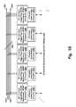
- FIG. 10is a system diagram illustrating a plurality of PLC devices constructed according to one or more embodiments of the present invention.
- a typical PLC installationmay include multiple instances of PLC circuitry/PLC interfaces, which are attached in differing ways depending on their common conductor linkages such as those shown with a 4 wire power main (perhaps 3 phase plus neutral power installation). Although a 4 wire power main is shown, a fewer or greater conductor power main is contemplated.
- a plurality of PLC devicescouple to the power main 1041 , which includes four conductors 1051 , 1053 , 1057 , and 1059 in the embodiment of FIG. 10 .
- Each PLC deviceis in a housing that includes PLC circuitry and non-PLC circuitry. Shown are five PLC devices.
- a first PLC deviceincludes PLC circuitry 1011 and non-PLC circuitry 1021 .
- a second PLC deviceincludes PLC circuitry 1013 and non-PLC circuitry 1023
- a third PLC deviceincludes PLC circuitry 1015 and non-PLC circuitry 1025
- a fourth PLC deviceincludes PLC circuitry 1017 and non-PLC circuitry 1027
- a fifth PLC deviceincludes PLC circuitry 1019 and non-PLC circuitry 1029 .
- all of these PLC devicesmay attempt to configure themselves and other PLC devices to communicate via the four conductor power mains 1041 .
- each PLC devicemay share one or more or all conductors of the power main with each other PLC device, i.e., any two PLC devices may share more than one, one, or none of the power main conductors, depending on the premises wiring and the underlying power plug connections.
- any two PLC devicesmay share a common conductor, such common conductor may not be sufficient for use in a PLC communication path because of distance limitations.
- each PLC devicevia its PLC circuitry, identifies all common conductor pathways between itself and other PLC devices.
- PLC circuitry supporting ACAM (Adaptive Conductor & Alternate Medium) redundancy, MIMO and diversity from each PLC devicei.e., PLC circuitry 1011 - 1019 , interacts with available conductor connections provided via outlet plugs to identify each other PLC device/circuitry on a conductor by conductor basis.
- ACAMAdaptive Conductor & Alternate Medium
- the PLC circuitry 1011might identify: a) conductors 1051 , 1053 being shared with the PLC circuitry 1017 ; b) conductors 1051 , 1053 , 1059 being shared with the PLC circuitry 1019 ; c) conductor 1053 being shared with the PLC circuitry 1013 ; and d) conductors 1053 , 1059 being shared with the PLC circuitry 1015 .
- the PLC circuitry 1011may establish communication with every other PLC device. Alternatively, if two conductors are needed, the PLC circuitry 1011 will be incapable of communicating with the PLC circuitry 1013 via a PLC pathway. In addition, if the distances between the PLC devices happen to be too great and/or if signaling impairments 1041 (filter, etc.) happen to exist in a conductor pathway, such conductor will not be available for PLC pathway use between PLC devices on either side of such impairment.
- the PLC circuitry 1011may only be able to establish PLC communication with the PLC circuitry 1015 due to a conductor pairing requirement and the impairment 1041 , while the PLC circuitry 1015 within another PLC device might also be able to support a PLC pathway to the PLC circuitry 1013 .
- communication flow between the PLC circuitry 1011 and the PLC circuitry 1013can be via (i) alternate communication path circuitry 1021 and 1023 (e.g., wireless communication pathways supported by the PLC devices, (ii) a routed PLC communication pathway via the PLC circuitry 1015 , etc.
- the PLC circuitry 1011shares three conductor pathways to the PLC circuitry 1019 .
- the alternate communication path circuitry 1021 and 1029may provide yet further communication links and even further conductors (when such paths comprise wired links). With all of these available pathways and underlying conductors and conductor pairing options, configuration decisions can be made to support current and ongoing communication flow with adaptation to such configurations on the fly. For example, PLC communication between the PLC circuitry 1013 and 1015 via the conductors 1053 , 1057 may cause the PLC circuitry 1011 , 1019 to avoid such conductors and only utilize the conductors 1051 and 1059 .
- multiple PLC conductors, multiple alternate path conductors, and multiple independent alternate and perhaps wireless pathscan be adaptively organized to manage communication flow between such PLC devices.
- Such organizationcan involve provision of multiple paths for redundancy, diversity, MIMO, duplexing, etc., performance.
- MIMOmight be established via a three conductor pair such as conductors 1051 , 1053 , 1059 between the PLC circuitry 1011 and 1019 .
- MIMOmay operate between conductors 1051 , 1059 and two conductors (not shown) that comprise part of the wired &/or wireless communication pathways 1031 via the circuitry 1021 , 1029 .
- MIMOmight be terminated and channelized flow might be established via perhaps a wireless link within the pathways 1031 and the pair of conductors 1051 , 1059 .
- portions of the overall traffice.g., based on QoS or upstream/downstream separation, etc.
- the channelsmight correspond to the two separate paths.
- each of the PLC circuitry 1011 , 1013 , 1015 , 1019might be made responsible for gaining and sharing access with other competing communication flows.
- one or more of such PLC circuitrymight be assigned an overall task of arbitrating or otherwise managing conductor and alternate pathway resource allocations.
- the PLC circuitry 1019 with connection to all power line conductors, i.e., the conductors 1051 - 1059might be made to send periodic beacons and arrange conductor allocations amongst all of the PLC circuitry/devices.
- Such allocation managementmay also take into consideration the available alternate communication paths, i.e., via the pathways 1031 , and their loading. Such consideration might also extend to full allocation management of such alternate communication pathways as well.
- PLC transmission power levelscan be adjusted, e.g., reduced to minimize interference, optimize power usage, etc., to address the a current conductor or conductor pairing pathway need.
- any of the five PLC devicesi.e., via their PLC circuitry 1011 - 1019 , can be active as a bridging element in a communication pathway between any other of the PLC devices.
- Such bridgingmay involve bridging from a first PLC conductor pair to a: (i) second PLC conductor pair (involving at least one different PLC conductor than those of the first PLC conductor pair); (ii) an alternate pathway conductor or pairing thereof; or (iii) an alternate wireless pathway.
- Such bridgingmay include bridging to an access point device that further couples with an Internet or intranet network.
- Full or half duplex flow managementmay also be used to help manage flow volume and sharing of a single conductor pairing with competing traffic.
- Duplexingcan also support split configurations such as MIMO downstream and bonded channel upstream, without MIMO.
- splitting of traffic based on QoS (Quality of Service)can be used, with or without MIMO, diversity, channel bonding, etc.
- Channel bondingcan also flow through different mediums. For example, instead of bonding between two pairings of PLC conductors, channel bonding can span one PLC conductor pairing plus an alternate communication path conductor pairing or grouping, or plus an alternate wireless communication pathway. Similarly, a communication pathway pairing might even involve one PLC conductor paired with one alternate communication pathway conductor.
- FIG. 10illustrates that many other embodiments are possible wherein adaptive reorganization of PLC and alternate communication path resources can be carried out.
- Such adaptationcan be upon installation via manual, automatic or automated configuration.
- Such adaptationcan be thereafter changed through user input or upon detecting a network topology or device change. Further, such changes can occur on-the-fly and in real time as conditions change.
- Circuitry described herein that performs particular functionsmay be a microprocessor, micro-controller, digital signal processor, microcomputer, central processing unit, field programmable gate array, programmable logic device, state machine, logic circuitry, analog circuitry, digital circuitry, and/or any device that manipulates signals (analog and/or digital) based on hard coding of the circuitry and/or operational instructions, which may be considered singularly or in combination a “processing module.”
- the processing module, module, processing circuit, and/or processing unitmay be, or further include, memory and/or an integrated memory element, which may be a single memory device, a plurality of memory devices, and/or embedded circuitry of another processing module, module, processing circuit, and/or processing unit.
- Such a memory devicemay be a read-only memory, random access memory, volatile memory, non-volatile memory, static memory, dynamic memory, flash memory, cache memory, and/or any device that stores digital information.
- the processing module, module, processing circuit, and/or processing unitincludes more than one processing device, the processing devices may be centrally located (e.g., directly coupled together via a wired and/or wireless bus structure) or may be distributed located (e.g., cloud computing via indirect coupling via a local area network and/or a wide area network).
- the processing module, module, processing circuit, and/or processing unitimplements one or more of its functions via a state machine, analog circuitry, digital circuitry, and/or logic circuitry
- the memory and/or memory element storing the corresponding operational instructionsmay be embedded within, or external to, the circuitry including the state machine, analog circuitry, digital circuitry, and/or logic circuitry.
- the memory elementmay store, and the processing module, module, processing circuit, and/or processing unit executes, hard coded and/or operational instructions corresponding to at least some of the steps and/or functions illustrated in one or more of the FIGs. Such a memory device or memory element can be included in an article of manufacture.
- the present inventionmay have also been described, at least in part, in terms of one or more embodiments.
- An embodiment of the present inventionis used herein to illustrate the present invention, an aspect thereof, a feature thereof, a concept thereof, and/or an example thereof.
- a physical embodiment of an apparatus, an article of manufacture, a machine, and/or of a process that embodies the present inventionmay include one or more of the aspects, features, concepts, examples, etc. described with reference to one or more of the embodiments discussed herein.
- the embodimentsmay incorporate the same or similarly named functions, steps, modules, etc. that may use the same or different reference numbers and, as such, the functions, steps, modules, etc. may be the same or similar functions, steps, modules, etc. or different ones.
- signals to, from, and/or between elements in a figure of any of the figures presented hereinmay be analog or digital, continuous time or discrete time, and single-ended or differential.
- signals to, from, and/or between elements in a figure of any of the figures presented hereinmay be analog or digital, continuous time or discrete time, and single-ended or differential.
- a signal pathis shown as a single-ended path, it also represents a differential signal path.
- a signal pathis shown as a differential path, it also represents a single-ended signal path.
- moduleis used in the description of the various embodiments of the present invention.
- a moduleincludes a processing module, a functional block, hardware, and/or software stored on memory for performing one or more functions as may be described herein. Note that, if the module is implemented via hardware, the hardware may operate independently and/or in conjunction software and/or firmware.
- a modulemay contain one or more sub-modules, each of which may be one or more modules.
Landscapes
- Engineering & Computer Science (AREA)
- Computer Networks & Wireless Communication (AREA)
- Signal Processing (AREA)
- Theoretical Computer Science (AREA)
- Power Engineering (AREA)
- Cable Transmission Systems, Equalization Of Radio And Reduction Of Echo (AREA)
- Analogue/Digital Conversion (AREA)
- Small-Scale Networks (AREA)
- Mobile Radio Communication Systems (AREA)
- Selective Calling Equipment (AREA)
Abstract
Description
Claims (20)
Priority Applications (1)
| Application Number | Priority Date | Filing Date | Title |
|---|---|---|---|
| US13/434,908US8750392B2 (en) | 2011-06-30 | 2012-03-30 | PLC device supporting MIMO operations |
Applications Claiming Priority (2)
| Application Number | Priority Date | Filing Date | Title |
|---|---|---|---|
| US201161503060P | 2011-06-30 | 2011-06-30 | |
| US13/434,908US8750392B2 (en) | 2011-06-30 | 2012-03-30 | PLC device supporting MIMO operations |
Publications (2)
| Publication Number | Publication Date |
|---|---|
| US20130003877A1 US20130003877A1 (en) | 2013-01-03 |
| US8750392B2true US8750392B2 (en) | 2014-06-10 |
Family
ID=47390618
Family Applications (9)
| Application Number | Title | Priority Date | Filing Date |
|---|---|---|---|
| US13/246,308ActiveUS8483291B2 (en) | 2011-06-30 | 2011-09-27 | Analog to digital converter with increased sub-range resolution |
| US13/246,585AbandonedUS20130003875A1 (en) | 2011-06-30 | 2011-09-27 | Powerline communication device with multiple plc interface(s) |
| US13/329,474AbandonedUS20130003876A1 (en) | 2011-06-30 | 2011-12-19 | Breaker box powerline communication device |
| US13/431,034AbandonedUS20130003696A1 (en) | 2011-06-30 | 2012-03-27 | Device handing over communication session from wireless communication to powerline communication |
| US13/432,144Active2032-05-23US9065465B2 (en) | 2011-06-30 | 2012-03-28 | PLC/wireless device coordinated wireless transmissions |
| US13/436,170ActiveUS8711951B2 (en) | 2011-06-30 | 2012-03-30 | Powerline communication device with load characterization functionality |
| US13/434,908ActiveUS8750392B2 (en) | 2011-06-30 | 2012-03-30 | PLC device supporting MIMO operations |
| US13/477,424Expired - Fee RelatedUS8837606B2 (en) | 2011-06-30 | 2012-05-22 | Powerline communication device noise timing based operations |
| US13/925,239ActiveUS8711952B2 (en) | 2011-06-30 | 2013-06-24 | Analog to digital converter with increased sub-range resolution |
Family Applications Before (6)
| Application Number | Title | Priority Date | Filing Date |
|---|---|---|---|
| US13/246,308ActiveUS8483291B2 (en) | 2011-06-30 | 2011-09-27 | Analog to digital converter with increased sub-range resolution |
| US13/246,585AbandonedUS20130003875A1 (en) | 2011-06-30 | 2011-09-27 | Powerline communication device with multiple plc interface(s) |
| US13/329,474AbandonedUS20130003876A1 (en) | 2011-06-30 | 2011-12-19 | Breaker box powerline communication device |
| US13/431,034AbandonedUS20130003696A1 (en) | 2011-06-30 | 2012-03-27 | Device handing over communication session from wireless communication to powerline communication |
| US13/432,144Active2032-05-23US9065465B2 (en) | 2011-06-30 | 2012-03-28 | PLC/wireless device coordinated wireless transmissions |
| US13/436,170ActiveUS8711951B2 (en) | 2011-06-30 | 2012-03-30 | Powerline communication device with load characterization functionality |
Family Applications After (2)
| Application Number | Title | Priority Date | Filing Date |
|---|---|---|---|
| US13/477,424Expired - Fee RelatedUS8837606B2 (en) | 2011-06-30 | 2012-05-22 | Powerline communication device noise timing based operations |
| US13/925,239ActiveUS8711952B2 (en) | 2011-06-30 | 2013-06-24 | Analog to digital converter with increased sub-range resolution |
Country Status (1)
| Country | Link |
|---|---|
| US (9) | US8483291B2 (en) |
Cited By (1)
| Publication number | Priority date | Publication date | Assignee | Title |
|---|---|---|---|---|
| US20150172036A1 (en)* | 2013-12-12 | 2015-06-18 | Qualcomm Incorporated | Neighbor network channel reuse with mimo capable stations |
Families Citing this family (203)
| Publication number | Priority date | Publication date | Assignee | Title |
|---|---|---|---|---|
| US8483291B2 (en)* | 2011-06-30 | 2013-07-09 | Broadcom Corporation | Analog to digital converter with increased sub-range resolution |
| US20130051220A1 (en)* | 2011-08-22 | 2013-02-28 | Igor Ryshakov | Method and Apparatus for Quick-Switch Fault Tolerant Backup Channel |
| JP6019950B2 (en)* | 2011-09-13 | 2016-11-02 | ソニー株式会社 | Power supply apparatus and method, and program |
| US9160410B2 (en)* | 2011-10-31 | 2015-10-13 | Texas Instruments Incorporated | Coexistence method by requesting access to the channel |
| US8787283B2 (en)* | 2011-11-21 | 2014-07-22 | Maxlinear, Inc. | Method and system for providing reduced bandwidth acquisition latency |
| US8767554B2 (en)* | 2011-11-21 | 2014-07-01 | Maxlinear, Inc. | Method and system for optimizing bandwidth utilization in an in-home network |
| TW201328193A (en)* | 2011-12-23 | 2013-07-01 | Hon Hai Prec Ind Co Ltd | Conversion device for devices with COM interface |
| US9755852B2 (en)* | 2012-05-11 | 2017-09-05 | Fsr Inc. | Power over ethernet to USB adapter |
| US9480014B2 (en)* | 2012-06-01 | 2016-10-25 | Qualcomm Incorporated | Device configuration in a hybrid communication network |
| US9378073B2 (en) | 2012-08-14 | 2016-06-28 | International Business Machines Corporation | Remote procedure call for a distributed system |
| US10135492B2 (en)* | 2012-11-07 | 2018-11-20 | Texas Instruments Incorporated | Compatible communication between devices using different communication protocols |
| US9113347B2 (en) | 2012-12-05 | 2015-08-18 | At&T Intellectual Property I, Lp | Backhaul link for distributed antenna system |
| US10009065B2 (en) | 2012-12-05 | 2018-06-26 | At&T Intellectual Property I, L.P. | Backhaul link for distributed antenna system |
| US9008073B1 (en)* | 2012-12-07 | 2015-04-14 | Maxim Integrated Products, Inc. | Routing for power line communication systems |
| US20140192679A1 (en)* | 2013-01-08 | 2014-07-10 | Tatung Company | Convergent Network Node with the Automatic Reconfiguration Capability |
| CN104113488A (en)* | 2013-04-16 | 2014-10-22 | 中兴通讯股份有限公司 | Interface switching method and interface switching device |
| US20140355610A1 (en)* | 2013-05-31 | 2014-12-04 | Qualcomm Incorporated | Switched power line communication |
| US9999038B2 (en) | 2013-05-31 | 2018-06-12 | At&T Intellectual Property I, L.P. | Remote distributed antenna system |
| US9525524B2 (en) | 2013-05-31 | 2016-12-20 | At&T Intellectual Property I, L.P. | Remote distributed antenna system |
| CN104378266A (en)* | 2013-08-16 | 2015-02-25 | 中兴通讯股份有限公司 | Communication method and system for home network and PLC device |
| CN103631363B (en)* | 2013-09-22 | 2017-05-10 | 深圳市联和安业科技有限公司 | Automobile data interface expanding device and method for achieving data interaction |
| KR102102706B1 (en)* | 2013-10-01 | 2020-05-29 | 삼성전자주식회사 | Receiver of NFC device and NFC device |
| US8897697B1 (en) | 2013-11-06 | 2014-11-25 | At&T Intellectual Property I, Lp | Millimeter-wave surface-wave communications |
| CN104144200A (en)* | 2013-12-09 | 2014-11-12 | 腾讯科技(深圳)有限公司 | Communication methods, communication side and user side for internet of things |
| US9209902B2 (en) | 2013-12-10 | 2015-12-08 | At&T Intellectual Property I, L.P. | Quasi-optical coupler |
| DE102013114563A1 (en)* | 2013-12-19 | 2015-06-25 | Valeo Schalter Und Sensoren Gmbh | A method for performing a parking operation of a motor vehicle in a transverse parking space, parking assistance system and motor vehicle |
| US9247435B2 (en)* | 2014-01-15 | 2016-01-26 | Qualcomm Incorporated | Null beamforming in a communication network |
| CN105323080B (en)* | 2014-06-09 | 2019-08-16 | 中兴通讯股份有限公司 | A kind of link backup, power supply backup method, apparatus and system |
| JP6421504B2 (en)* | 2014-07-28 | 2018-11-14 | ソニー株式会社 | Image processing apparatus and image processing method |
| DE102014012318B4 (en)* | 2014-08-19 | 2019-05-09 | Audi Ag | A method for predicting a consumption of a motor vehicle, motor vehicle and computer program |
| KR101827754B1 (en)* | 2014-08-25 | 2018-03-22 | 원 미디어, 엘엘씨 | Method for dynamic configuration of a flexible orthogonal frequency division multiplexing phy transport data frame preamble |
| US9692101B2 (en) | 2014-08-26 | 2017-06-27 | At&T Intellectual Property I, L.P. | Guided wave couplers for coupling electromagnetic waves between a waveguide surface and a surface of a wire |
| US9768833B2 (en) | 2014-09-15 | 2017-09-19 | At&T Intellectual Property I, L.P. | Method and apparatus for sensing a condition in a transmission medium of electromagnetic waves |
| US10063280B2 (en) | 2014-09-17 | 2018-08-28 | At&T Intellectual Property I, L.P. | Monitoring and mitigating conditions in a communication network |
| US9628854B2 (en) | 2014-09-29 | 2017-04-18 | At&T Intellectual Property I, L.P. | Method and apparatus for distributing content in a communication network |
| US9615269B2 (en) | 2014-10-02 | 2017-04-04 | At&T Intellectual Property I, L.P. | Method and apparatus that provides fault tolerance in a communication network |
| US9685992B2 (en)* | 2014-10-03 | 2017-06-20 | At&T Intellectual Property I, L.P. | Circuit panel network and methods thereof |
| US9503189B2 (en) | 2014-10-10 | 2016-11-22 | At&T Intellectual Property I, L.P. | Method and apparatus for arranging communication sessions in a communication system |
| US9762289B2 (en) | 2014-10-14 | 2017-09-12 | At&T Intellectual Property I, L.P. | Method and apparatus for transmitting or receiving signals in a transportation system |
| US9973299B2 (en) | 2014-10-14 | 2018-05-15 | At&T Intellectual Property I, L.P. | Method and apparatus for adjusting a mode of communication in a communication network |
| US9520945B2 (en) | 2014-10-21 | 2016-12-13 | At&T Intellectual Property I, L.P. | Apparatus for providing communication services and methods thereof |
| US9312919B1 (en) | 2014-10-21 | 2016-04-12 | At&T Intellectual Property I, Lp | Transmission device with impairment compensation and methods for use therewith |
| US9627768B2 (en) | 2014-10-21 | 2017-04-18 | At&T Intellectual Property I, L.P. | Guided-wave transmission device with non-fundamental mode propagation and methods for use therewith |
| US9653770B2 (en) | 2014-10-21 | 2017-05-16 | At&T Intellectual Property I, L.P. | Guided wave coupler, coupling module and methods for use therewith |
| US9577306B2 (en) | 2014-10-21 | 2017-02-21 | At&T Intellectual Property I, L.P. | Guided-wave transmission device and methods for use therewith |
| US9780834B2 (en) | 2014-10-21 | 2017-10-03 | At&T Intellectual Property I, L.P. | Method and apparatus for transmitting electromagnetic waves |
| US9769020B2 (en) | 2014-10-21 | 2017-09-19 | At&T Intellectual Property I, L.P. | Method and apparatus for responding to events affecting communications in a communication network |
| US9564947B2 (en) | 2014-10-21 | 2017-02-07 | At&T Intellectual Property I, L.P. | Guided-wave transmission device with diversity and methods for use therewith |
| US9461706B1 (en) | 2015-07-31 | 2016-10-04 | At&T Intellectual Property I, Lp | Method and apparatus for exchanging communication signals |
| US9544006B2 (en) | 2014-11-20 | 2017-01-10 | At&T Intellectual Property I, L.P. | Transmission device with mode division multiplexing and methods for use therewith |
| US10009067B2 (en) | 2014-12-04 | 2018-06-26 | At&T Intellectual Property I, L.P. | Method and apparatus for configuring a communication interface |
| US9997819B2 (en) | 2015-06-09 | 2018-06-12 | At&T Intellectual Property I, L.P. | Transmission medium and method for facilitating propagation of electromagnetic waves via a core |
| US10243784B2 (en) | 2014-11-20 | 2019-03-26 | At&T Intellectual Property I, L.P. | System for generating topology information and methods thereof |
| US9800327B2 (en) | 2014-11-20 | 2017-10-24 | At&T Intellectual Property I, L.P. | Apparatus for controlling operations of a communication device and methods thereof |
| US9954287B2 (en) | 2014-11-20 | 2018-04-24 | At&T Intellectual Property I, L.P. | Apparatus for converting wireless signals and electromagnetic waves and methods thereof |
| US9742462B2 (en) | 2014-12-04 | 2017-08-22 | At&T Intellectual Property I, L.P. | Transmission medium and communication interfaces and methods for use therewith |
| US9680670B2 (en) | 2014-11-20 | 2017-06-13 | At&T Intellectual Property I, L.P. | Transmission device with channel equalization and control and methods for use therewith |
| US10340573B2 (en) | 2016-10-26 | 2019-07-02 | At&T Intellectual Property I, L.P. | Launcher with cylindrical coupling device and methods for use therewith |
| US9654173B2 (en) | 2014-11-20 | 2017-05-16 | At&T Intellectual Property I, L.P. | Apparatus for powering a communication device and methods thereof |
| US10144036B2 (en) | 2015-01-30 | 2018-12-04 | At&T Intellectual Property I, L.P. | Method and apparatus for mitigating interference affecting a propagation of electromagnetic waves guided by a transmission medium |
| US9654134B2 (en) | 2015-02-16 | 2017-05-16 | Sound Devices Llc | High dynamic range analog-to-digital conversion with selective regression based data repair |
| US9876570B2 (en) | 2015-02-20 | 2018-01-23 | At&T Intellectual Property I, Lp | Guided-wave transmission device with non-fundamental mode propagation and methods for use therewith |
| CN110661590B (en) | 2015-03-09 | 2021-04-20 | 第一媒体有限责任公司 | System Discovery and Signaling |
| US9749013B2 (en) | 2015-03-17 | 2017-08-29 | At&T Intellectual Property I, L.P. | Method and apparatus for reducing attenuation of electromagnetic waves guided by a transmission medium |
| US10224981B2 (en) | 2015-04-24 | 2019-03-05 | At&T Intellectual Property I, Lp | Passive electrical coupling device and methods for use therewith |
| US9705561B2 (en) | 2015-04-24 | 2017-07-11 | At&T Intellectual Property I, L.P. | Directional coupling device and methods for use therewith |
| US9793954B2 (en) | 2015-04-28 | 2017-10-17 | At&T Intellectual Property I, L.P. | Magnetic coupling device and methods for use therewith |
| US9871282B2 (en) | 2015-05-14 | 2018-01-16 | At&T Intellectual Property I, L.P. | At least one transmission medium having a dielectric surface that is covered at least in part by a second dielectric |
| US9748626B2 (en) | 2015-05-14 | 2017-08-29 | At&T Intellectual Property I, L.P. | Plurality of cables having different cross-sectional shapes which are bundled together to form a transmission medium |
| US9490869B1 (en) | 2015-05-14 | 2016-11-08 | At&T Intellectual Property I, L.P. | Transmission medium having multiple cores and methods for use therewith |
| US10650940B2 (en) | 2015-05-15 | 2020-05-12 | At&T Intellectual Property I, L.P. | Transmission medium having a conductive material and methods for use therewith |
| US10679767B2 (en) | 2015-05-15 | 2020-06-09 | At&T Intellectual Property I, L.P. | Transmission medium having a conductive material and methods for use therewith |
| US9917341B2 (en) | 2015-05-27 | 2018-03-13 | At&T Intellectual Property I, L.P. | Apparatus and method for launching electromagnetic waves and for modifying radial dimensions of the propagating electromagnetic waves |
| US9912381B2 (en) | 2015-06-03 | 2018-03-06 | At&T Intellectual Property I, Lp | Network termination and methods for use therewith |
| US10154493B2 (en) | 2015-06-03 | 2018-12-11 | At&T Intellectual Property I, L.P. | Network termination and methods for use therewith |
| US10103801B2 (en) | 2015-06-03 | 2018-10-16 | At&T Intellectual Property I, L.P. | Host node device and methods for use therewith |
| US10812174B2 (en) | 2015-06-03 | 2020-10-20 | At&T Intellectual Property I, L.P. | Client node device and methods for use therewith |
| US9866309B2 (en) | 2015-06-03 | 2018-01-09 | At&T Intellectual Property I, Lp | Host node device and methods for use therewith |
| US10348391B2 (en) | 2015-06-03 | 2019-07-09 | At&T Intellectual Property I, L.P. | Client node device with frequency conversion and methods for use therewith |
| US9913139B2 (en) | 2015-06-09 | 2018-03-06 | At&T Intellectual Property I, L.P. | Signal fingerprinting for authentication of communicating devices |
| US10142086B2 (en) | 2015-06-11 | 2018-11-27 | At&T Intellectual Property I, L.P. | Repeater and methods for use therewith |
| US9608692B2 (en) | 2015-06-11 | 2017-03-28 | At&T Intellectual Property I, L.P. | Repeater and methods for use therewith |
| US9820146B2 (en) | 2015-06-12 | 2017-11-14 | At&T Intellectual Property I, L.P. | Method and apparatus for authentication and identity management of communicating devices |
| US9667317B2 (en) | 2015-06-15 | 2017-05-30 | At&T Intellectual Property I, L.P. | Method and apparatus for providing security using network traffic adjustments |
| US9640850B2 (en) | 2015-06-25 | 2017-05-02 | At&T Intellectual Property I, L.P. | Methods and apparatus for inducing a non-fundamental wave mode on a transmission medium |
| US9509415B1 (en) | 2015-06-25 | 2016-11-29 | At&T Intellectual Property I, L.P. | Methods and apparatus for inducing a fundamental wave mode on a transmission medium |
| US9865911B2 (en) | 2015-06-25 | 2018-01-09 | At&T Intellectual Property I, L.P. | Waveguide system for slot radiating first electromagnetic waves that are combined into a non-fundamental wave mode second electromagnetic wave on a transmission medium |
| US10170840B2 (en) | 2015-07-14 | 2019-01-01 | At&T Intellectual Property I, L.P. | Apparatus and methods for sending or receiving electromagnetic signals |
| US10044409B2 (en) | 2015-07-14 | 2018-08-07 | At&T Intellectual Property I, L.P. | Transmission medium and methods for use therewith |
| US10033107B2 (en) | 2015-07-14 | 2018-07-24 | At&T Intellectual Property I, L.P. | Method and apparatus for coupling an antenna to a device |
| US10033108B2 (en) | 2015-07-14 | 2018-07-24 | At&T Intellectual Property I, L.P. | Apparatus and methods for generating an electromagnetic wave having a wave mode that mitigates interference |
| US9853342B2 (en) | 2015-07-14 | 2017-12-26 | At&T Intellectual Property I, L.P. | Dielectric transmission medium connector and methods for use therewith |
| US9882257B2 (en) | 2015-07-14 | 2018-01-30 | At&T Intellectual Property I, L.P. | Method and apparatus for launching a wave mode that mitigates interference |
| US10148016B2 (en) | 2015-07-14 | 2018-12-04 | At&T Intellectual Property I, L.P. | Apparatus and methods for communicating utilizing an antenna array |
| US9836957B2 (en) | 2015-07-14 | 2017-12-05 | At&T Intellectual Property I, L.P. | Method and apparatus for communicating with premises equipment |
| US9847566B2 (en) | 2015-07-14 | 2017-12-19 | At&T Intellectual Property I, L.P. | Method and apparatus for adjusting a field of a signal to mitigate interference |
| US10341142B2 (en) | 2015-07-14 | 2019-07-02 | At&T Intellectual Property I, L.P. | Apparatus and methods for generating non-interfering electromagnetic waves on an uninsulated conductor |
| US9722318B2 (en) | 2015-07-14 | 2017-08-01 | At&T Intellectual Property I, L.P. | Method and apparatus for coupling an antenna to a device |
| US10320586B2 (en) | 2015-07-14 | 2019-06-11 | At&T Intellectual Property I, L.P. | Apparatus and methods for generating non-interfering electromagnetic waves on an insulated transmission medium |
| US9628116B2 (en) | 2015-07-14 | 2017-04-18 | At&T Intellectual Property I, L.P. | Apparatus and methods for transmitting wireless signals |
| US10205655B2 (en) | 2015-07-14 | 2019-02-12 | At&T Intellectual Property I, L.P. | Apparatus and methods for communicating utilizing an antenna array and multiple communication paths |
| US10090606B2 (en) | 2015-07-15 | 2018-10-02 | At&T Intellectual Property I, L.P. | Antenna system with dielectric array and methods for use therewith |
| US9793951B2 (en) | 2015-07-15 | 2017-10-17 | At&T Intellectual Property I, L.P. | Method and apparatus for launching a wave mode that mitigates interference |
| US9608740B2 (en) | 2015-07-15 | 2017-03-28 | At&T Intellectual Property I, L.P. | Method and apparatus for launching a wave mode that mitigates interference |
| US10784670B2 (en) | 2015-07-23 | 2020-09-22 | At&T Intellectual Property I, L.P. | Antenna support for aligning an antenna |
| US9871283B2 (en) | 2015-07-23 | 2018-01-16 | At&T Intellectual Property I, Lp | Transmission medium having a dielectric core comprised of plural members connected by a ball and socket configuration |
| US9912027B2 (en) | 2015-07-23 | 2018-03-06 | At&T Intellectual Property I, L.P. | Method and apparatus for exchanging communication signals |
| US9948333B2 (en) | 2015-07-23 | 2018-04-17 | At&T Intellectual Property I, L.P. | Method and apparatus for wireless communications to mitigate interference |
| US9749053B2 (en) | 2015-07-23 | 2017-08-29 | At&T Intellectual Property I, L.P. | Node device, repeater and methods for use therewith |
| US9735833B2 (en) | 2015-07-31 | 2017-08-15 | At&T Intellectual Property I, L.P. | Method and apparatus for communications management in a neighborhood network |
| US10020587B2 (en) | 2015-07-31 | 2018-07-10 | At&T Intellectual Property I, L.P. | Radial antenna and methods for use therewith |
| US9967173B2 (en) | 2015-07-31 | 2018-05-08 | At&T Intellectual Property I, L.P. | Method and apparatus for authentication and identity management of communicating devices |
| US9904535B2 (en) | 2015-09-14 | 2018-02-27 | At&T Intellectual Property I, L.P. | Method and apparatus for distributing software |
| US9705571B2 (en) | 2015-09-16 | 2017-07-11 | At&T Intellectual Property I, L.P. | Method and apparatus for use with a radio distributed antenna system |
| US10051629B2 (en) | 2015-09-16 | 2018-08-14 | At&T Intellectual Property I, L.P. | Method and apparatus for use with a radio distributed antenna system having an in-band reference signal |
| US10136434B2 (en) | 2015-09-16 | 2018-11-20 | At&T Intellectual Property I, L.P. | Method and apparatus for use with a radio distributed antenna system having an ultra-wideband control channel |
| US10079661B2 (en) | 2015-09-16 | 2018-09-18 | At&T Intellectual Property I, L.P. | Method and apparatus for use with a radio distributed antenna system having a clock reference |
| US10009063B2 (en) | 2015-09-16 | 2018-06-26 | At&T Intellectual Property I, L.P. | Method and apparatus for use with a radio distributed antenna system having an out-of-band reference signal |
| US10009901B2 (en) | 2015-09-16 | 2018-06-26 | At&T Intellectual Property I, L.P. | Method, apparatus, and computer-readable storage medium for managing utilization of wireless resources between base stations |
| US9769128B2 (en) | 2015-09-28 | 2017-09-19 | At&T Intellectual Property I, L.P. | Method and apparatus for encryption of communications over a network |
| US9729197B2 (en) | 2015-10-01 | 2017-08-08 | At&T Intellectual Property I, L.P. | Method and apparatus for communicating network management traffic over a network |
| US9882277B2 (en) | 2015-10-02 | 2018-01-30 | At&T Intellectual Property I, Lp | Communication device and antenna assembly with actuated gimbal mount |
| US9876264B2 (en) | 2015-10-02 | 2018-01-23 | At&T Intellectual Property I, Lp | Communication system, guided wave switch and methods for use therewith |
| US10074890B2 (en) | 2015-10-02 | 2018-09-11 | At&T Intellectual Property I, L.P. | Communication device and antenna with integrated light assembly |
| US10051483B2 (en) | 2015-10-16 | 2018-08-14 | At&T Intellectual Property I, L.P. | Method and apparatus for directing wireless signals |
| US10355367B2 (en) | 2015-10-16 | 2019-07-16 | At&T Intellectual Property I, L.P. | Antenna structure for exchanging wireless signals |
| US10665942B2 (en) | 2015-10-16 | 2020-05-26 | At&T Intellectual Property I, L.P. | Method and apparatus for adjusting wireless communications |
| US20170126421A1 (en) | 2015-10-29 | 2017-05-04 | Not for Radio, LLC | Fixture data over powerline network |
| JP6791238B2 (en)* | 2016-02-22 | 2020-11-25 | コニカミノルタ株式会社 | Portable radiation imaging device |
| JP6546867B2 (en)* | 2016-03-10 | 2019-07-17 | 東京エレクトロン株式会社 | How to adjust the processing process |
| KR20170106862A (en)* | 2016-03-14 | 2017-09-22 | 삼성전자주식회사 | Method for synchronizing data and electronic apparatus and system implementing the same |
| US9912419B1 (en) | 2016-08-24 | 2018-03-06 | At&T Intellectual Property I, L.P. | Method and apparatus for managing a fault in a distributed antenna system |
| US9860075B1 (en) | 2016-08-26 | 2018-01-02 | At&T Intellectual Property I, L.P. | Method and communication node for broadband distribution |
| US10291311B2 (en) | 2016-09-09 | 2019-05-14 | At&T Intellectual Property I, L.P. | Method and apparatus for mitigating a fault in a distributed antenna system |
| US11032819B2 (en) | 2016-09-15 | 2021-06-08 | At&T Intellectual Property I, L.P. | Method and apparatus for use with a radio distributed antenna system having a control channel reference signal |
| US10135146B2 (en) | 2016-10-18 | 2018-11-20 | At&T Intellectual Property I, L.P. | Apparatus and methods for launching guided waves via circuits |
| US10135147B2 (en) | 2016-10-18 | 2018-11-20 | At&T Intellectual Property I, L.P. | Apparatus and methods for launching guided waves via an antenna |
| US10340600B2 (en) | 2016-10-18 | 2019-07-02 | At&T Intellectual Property I, L.P. | Apparatus and methods for launching guided waves via plural waveguide systems |
| US9991580B2 (en) | 2016-10-21 | 2018-06-05 | At&T Intellectual Property I, L.P. | Launcher and coupling system for guided wave mode cancellation |
| US10811767B2 (en) | 2016-10-21 | 2020-10-20 | At&T Intellectual Property I, L.P. | System and dielectric antenna with convex dielectric radome |
| US9876605B1 (en) | 2016-10-21 | 2018-01-23 | At&T Intellectual Property I, L.P. | Launcher and coupling system to support desired guided wave mode |
| US10374316B2 (en) | 2016-10-21 | 2019-08-06 | At&T Intellectual Property I, L.P. | System and dielectric antenna with non-uniform dielectric |
| US10312567B2 (en) | 2016-10-26 | 2019-06-04 | At&T Intellectual Property I, L.P. | Launcher with planar strip antenna and methods for use therewith |
| US10224634B2 (en) | 2016-11-03 | 2019-03-05 | At&T Intellectual Property I, L.P. | Methods and apparatus for adjusting an operational characteristic of an antenna |
| US10225025B2 (en) | 2016-11-03 | 2019-03-05 | At&T Intellectual Property I, L.P. | Method and apparatus for detecting a fault in a communication system |
| US10291334B2 (en) | 2016-11-03 | 2019-05-14 | At&T Intellectual Property I, L.P. | System for detecting a fault in a communication system |
| US10498044B2 (en) | 2016-11-03 | 2019-12-03 | At&T Intellectual Property I, L.P. | Apparatus for configuring a surface of an antenna |
| US10340601B2 (en) | 2016-11-23 | 2019-07-02 | At&T Intellectual Property I, L.P. | Multi-antenna system and methods for use therewith |
| US10340603B2 (en) | 2016-11-23 | 2019-07-02 | At&T Intellectual Property I, L.P. | Antenna system having shielded structural configurations for assembly |
| US10090594B2 (en) | 2016-11-23 | 2018-10-02 | At&T Intellectual Property I, L.P. | Antenna system having structural configurations for assembly |
| US10535928B2 (en) | 2016-11-23 | 2020-01-14 | At&T Intellectual Property I, L.P. | Antenna system and methods for use therewith |
| US10178445B2 (en) | 2016-11-23 | 2019-01-08 | At&T Intellectual Property I, L.P. | Methods, devices, and systems for load balancing between a plurality of waveguides |
| US10361489B2 (en) | 2016-12-01 | 2019-07-23 | At&T Intellectual Property I, L.P. | Dielectric dish antenna system and methods for use therewith |
| US10305190B2 (en) | 2016-12-01 | 2019-05-28 | At&T Intellectual Property I, L.P. | Reflecting dielectric antenna system and methods for use therewith |
| US10694379B2 (en) | 2016-12-06 | 2020-06-23 | At&T Intellectual Property I, L.P. | Waveguide system with device-based authentication and methods for use therewith |
| US10382976B2 (en) | 2016-12-06 | 2019-08-13 | At&T Intellectual Property I, L.P. | Method and apparatus for managing wireless communications based on communication paths and network device positions |
| US10326494B2 (en) | 2016-12-06 | 2019-06-18 | At&T Intellectual Property I, L.P. | Apparatus for measurement de-embedding and methods for use therewith |
| US10020844B2 (en) | 2016-12-06 | 2018-07-10 | T&T Intellectual Property I, L.P. | Method and apparatus for broadcast communication via guided waves |
| US9927517B1 (en) | 2016-12-06 | 2018-03-27 | At&T Intellectual Property I, L.P. | Apparatus and methods for sensing rainfall |
| US10439675B2 (en) | 2016-12-06 | 2019-10-08 | At&T Intellectual Property I, L.P. | Method and apparatus for repeating guided wave communication signals |
| US10819035B2 (en) | 2016-12-06 | 2020-10-27 | At&T Intellectual Property I, L.P. | Launcher with helical antenna and methods for use therewith |
| US10727599B2 (en) | 2016-12-06 | 2020-07-28 | At&T Intellectual Property I, L.P. | Launcher with slot antenna and methods for use therewith |
| US10135145B2 (en) | 2016-12-06 | 2018-11-20 | At&T Intellectual Property I, L.P. | Apparatus and methods for generating an electromagnetic wave along a transmission medium |
| US10755542B2 (en) | 2016-12-06 | 2020-08-25 | At&T Intellectual Property I, L.P. | Method and apparatus for surveillance via guided wave communication |
| US10637149B2 (en) | 2016-12-06 | 2020-04-28 | At&T Intellectual Property I, L.P. | Injection molded dielectric antenna and methods for use therewith |
| US10243270B2 (en) | 2016-12-07 | 2019-03-26 | At&T Intellectual Property I, L.P. | Beam adaptive multi-feed dielectric antenna system and methods for use therewith |
| US10446936B2 (en) | 2016-12-07 | 2019-10-15 | At&T Intellectual Property I, L.P. | Multi-feed dielectric antenna system and methods for use therewith |
| US10359749B2 (en) | 2016-12-07 | 2019-07-23 | At&T Intellectual Property I, L.P. | Method and apparatus for utilities management via guided wave communication |
| US10168695B2 (en) | 2016-12-07 | 2019-01-01 | At&T Intellectual Property I, L.P. | Method and apparatus for controlling an unmanned aircraft |
| US10139820B2 (en) | 2016-12-07 | 2018-11-27 | At&T Intellectual Property I, L.P. | Method and apparatus for deploying equipment of a communication system |
| US10389029B2 (en) | 2016-12-07 | 2019-08-20 | At&T Intellectual Property I, L.P. | Multi-feed dielectric antenna system with core selection and methods for use therewith |
| US10547348B2 (en) | 2016-12-07 | 2020-01-28 | At&T Intellectual Property I, L.P. | Method and apparatus for switching transmission mediums in a communication system |
| US9893795B1 (en) | 2016-12-07 | 2018-02-13 | At&T Intellectual Property I, Lp | Method and repeater for broadband distribution |
| US10027397B2 (en) | 2016-12-07 | 2018-07-17 | At&T Intellectual Property I, L.P. | Distributed antenna system and methods for use therewith |
| US10916969B2 (en) | 2016-12-08 | 2021-02-09 | At&T Intellectual Property I, L.P. | Method and apparatus for providing power using an inductive coupling |
| US10389037B2 (en) | 2016-12-08 | 2019-08-20 | At&T Intellectual Property I, L.P. | Apparatus and methods for selecting sections of an antenna array and use therewith |
| US10326689B2 (en) | 2016-12-08 | 2019-06-18 | At&T Intellectual Property I, L.P. | Method and system for providing alternative communication paths |
| US10601494B2 (en) | 2016-12-08 | 2020-03-24 | At&T Intellectual Property I, L.P. | Dual-band communication device and method for use therewith |
| US10938108B2 (en) | 2016-12-08 | 2021-03-02 | At&T Intellectual Property I, L.P. | Frequency selective multi-feed dielectric antenna system and methods for use therewith |
| US10530505B2 (en) | 2016-12-08 | 2020-01-07 | At&T Intellectual Property I, L.P. | Apparatus and methods for launching electromagnetic waves along a transmission medium |
| US9911020B1 (en) | 2016-12-08 | 2018-03-06 | At&T Intellectual Property I, L.P. | Method and apparatus for tracking via a radio frequency identification device |
| US10411356B2 (en) | 2016-12-08 | 2019-09-10 | At&T Intellectual Property I, L.P. | Apparatus and methods for selectively targeting communication devices with an antenna array |
| US10069535B2 (en) | 2016-12-08 | 2018-09-04 | At&T Intellectual Property I, L.P. | Apparatus and methods for launching electromagnetic waves having a certain electric field structure |
| US9998870B1 (en) | 2016-12-08 | 2018-06-12 | At&T Intellectual Property I, L.P. | Method and apparatus for proximity sensing |
| US10777873B2 (en) | 2016-12-08 | 2020-09-15 | At&T Intellectual Property I, L.P. | Method and apparatus for mounting network devices |
| US10103422B2 (en) | 2016-12-08 | 2018-10-16 | At&T Intellectual Property I, L.P. | Method and apparatus for mounting network devices |
| US10264586B2 (en) | 2016-12-09 | 2019-04-16 | At&T Mobility Ii Llc | Cloud-based packet controller and methods for use therewith |
| US10340983B2 (en) | 2016-12-09 | 2019-07-02 | At&T Intellectual Property I, L.P. | Method and apparatus for surveying remote sites via guided wave communications |
| US9838896B1 (en) | 2016-12-09 | 2017-12-05 | At&T Intellectual Property I, L.P. | Method and apparatus for assessing network coverage |
| US10312953B2 (en) | 2016-12-26 | 2019-06-04 | Industrial Technology Research Institute | Orthogonal frequency division multiplexing receiver with low-resolution analog to digital converter and electronic device thereof |
| KR20180098059A (en)* | 2017-02-24 | 2018-09-03 | 엘지전자 주식회사 | Mobile terminal |
| US9973940B1 (en) | 2017-02-27 | 2018-05-15 | At&T Intellectual Property I, L.P. | Apparatus and methods for dynamic impedance matching of a guided wave launcher |
| US10298293B2 (en) | 2017-03-13 | 2019-05-21 | At&T Intellectual Property I, L.P. | Apparatus of communication utilizing wireless network devices |
| US10103780B1 (en)* | 2017-03-31 | 2018-10-16 | GM Global Technology Operations LLC | Dual mode communication over automotive power lines |
| EP3404886A1 (en)* | 2017-05-15 | 2018-11-21 | IMEC vzw | Network stack for a plurality of physical communication interfaces |
| US10554235B2 (en)* | 2017-11-06 | 2020-02-04 | At&T Intellectual Property I, L.P. | Multi-input multi-output guided wave system and methods for use therewith |
| US10292111B1 (en)* | 2018-03-14 | 2019-05-14 | Corning Optical Communications LLC | Gain control circuit supporting dynamic gain control in a remote unit in a wireless distribution system (WDS) |
| CN108390700B (en)* | 2018-04-17 | 2024-05-14 | 东莞市慧眼数字技术有限公司 | Coupling device for feeding detection signal into high-voltage carrier wave |
| CN112602291B (en)* | 2018-08-27 | 2022-04-05 | 华为技术有限公司 | Communication device, system and method thereof |
| US20200145824A1 (en)* | 2018-11-05 | 2020-05-07 | Comcast Cable Communications, Llc | Localized Multi-Factor Network Authentication |
| IL263929A (en)* | 2018-12-24 | 2020-06-30 | S G A Innovations Ltd | Systems, devices, and methods for detecting and/or preventing communication over power lines |
| US10763918B1 (en) | 2019-06-10 | 2020-09-01 | Baker Hughes, A Ge Company, Llc | Time synchronization of bottom hole assembly components via powerline communication |
| CN113660691B (en)* | 2021-10-19 | 2022-03-11 | 国网江西省电力有限公司经济技术研究院 | Medium-voltage MIMO-PLC access terminal state monitoring device |
Citations (6)
| Publication number | Priority date | Publication date | Assignee | Title |
|---|---|---|---|---|
| US20050068223A1 (en)* | 2002-01-09 | 2005-03-31 | Vavik Geir Monsen | Analogue regenerative transponders including regenerative transponder systems |
| US7269403B1 (en) | 2004-06-03 | 2007-09-11 | Miao George J | Dual-mode wireless and wired power line communications |
| US20080273613A1 (en) | 2007-05-02 | 2008-11-06 | Boaz Kol | Multiple input, multiple output (mimo) communication system over in-premises wires |
| US20100061433A1 (en) | 2007-08-22 | 2010-03-11 | Sony Corporation | Method for transmitting a signal via a power line network, transmitter, receiver, power line communication modem and power line communication system |
| US20110286152A1 (en)* | 2010-05-07 | 2011-11-24 | Automated Media Services, Inc. | Mechanical and electrical system for powering shelf-edge electronic displays in a retail environment |
| US20130039362A1 (en)* | 2007-08-09 | 2013-02-14 | Phybridge Inc. | Inline power system and method for network communications |
Family Cites Families (46)
| Publication number | Priority date | Publication date | Assignee | Title |
|---|---|---|---|---|
| DE2402127C3 (en)* | 1974-01-17 | 1978-04-06 | Pluess-Staufer Ag, Oftringen (Schweiz) | Device for measuring the haze of surfaces |
| US5250948A (en)* | 1991-12-19 | 1993-10-05 | Eastman Kodak Company | High level resolution enhancement for dual-range A/D conversion |
| US6285309B1 (en)* | 1999-09-14 | 2001-09-04 | Texas Instruments Incorporated | Nested pipelined analog-to-digital converter |
| WO2001084806A2 (en)* | 2000-05-02 | 2001-11-08 | Phonex Broadband Corporation | Method and system for adapting a telephone line modem for use on the power line |
| US6870515B2 (en)* | 2000-12-28 | 2005-03-22 | Nortel Networks Limited | MIMO wireless communication system |
| US7194528B1 (en)* | 2001-05-18 | 2007-03-20 | Current Grid, Llc | Method and apparatus for processing inbound data within a powerline based communication system |
| JP4075461B2 (en)* | 2001-11-27 | 2008-04-16 | ソニー株式会社 | Communication system, communication terminal, and communication method |
| WO2003063380A2 (en)* | 2002-01-24 | 2003-07-31 | Matsushita Electric Industrial Co., Ltd. | Method of and system for power line carrier communications |
| US7308103B2 (en)* | 2003-05-08 | 2007-12-11 | Current Technologies, Llc | Power line communication device and method of using the same |
| US20050085259A1 (en)* | 2003-10-15 | 2005-04-21 | Conner W. S. | Technique to coordinate wireless network over a power line or other wired back channel |
| US20050181839A1 (en)* | 2004-02-17 | 2005-08-18 | Nokia Corporation | Devices and methods for simultaneous battery charging and data transmission in a mobile terminal |
| US7675979B1 (en)* | 2004-07-20 | 2010-03-09 | Marvell International Ltd. | Methods, algorithms, software, circuits, architectures, and systems for improved communications over cyclostationary channels |
| US8290498B2 (en)* | 2004-07-28 | 2012-10-16 | Broadcom Corporation | Mobile handoff through multi-network simulcasting |
| US20060267788A1 (en)* | 2005-01-21 | 2006-11-30 | Delany George B | Method and apparatus for illuminating a wall plate |
| US7215274B2 (en)* | 2005-07-29 | 2007-05-08 | Agere Systems Inc. | Reference voltage pre-charge in a multi-step sub-ranging analog-to-digital converter |
| EP1770870B1 (en)* | 2005-10-03 | 2019-04-03 | Avago Technologies International Sales Pte. Limited | Powerline communication device and method |
| US20070076666A1 (en)* | 2005-10-03 | 2007-04-05 | Riveiro Juan C | Multi-Wideband Communications over Power Lines |
| WO2008032225A2 (en)* | 2006-03-21 | 2008-03-20 | Ranco Incorporated Of Delaware | Refrigeration monitor unit |
| US7929940B1 (en)* | 2006-04-18 | 2011-04-19 | Nextel Communications Inc. | System and method for transmitting wireless digital service signals via power transmission lines |
| JP5061111B2 (en)* | 2006-09-15 | 2012-10-31 | パナソニック株式会社 | Speech coding apparatus and speech coding method |
| GB2443234B8 (en)* | 2006-10-24 | 2009-01-28 | Innovision Res & Tech Plc | Near field RF communicators and near field RF communications enabled devices |
| US8489344B2 (en)* | 2007-02-09 | 2013-07-16 | Adaptive Spectrum And Signal Alignment, Inc. | Home network system augmentation with remote guidance and local set up and monitoring |
| JP2008270999A (en)* | 2007-04-18 | 2008-11-06 | Sony Corp | Communicating system and communication equipment |
| US8352768B2 (en)* | 2007-04-27 | 2013-01-08 | At&T Intellectual Property I, L.P. | Controlling power states of a peripheral device in response to user proximity |
| JP4922848B2 (en)* | 2007-06-28 | 2012-04-25 | オリンパス株式会社 | Portable terminal device and network connection control method |
| EP2019496B1 (en)* | 2007-07-23 | 2017-06-07 | Sony Corporation | Method for transmitting a signal between a transmitter and a receiver in a power line network, transmitter, receiver, power line communication modem and powerline communication system |
| JP5328662B2 (en)* | 2007-10-02 | 2013-10-30 | パナソニック株式会社 | Electronic apparatus and image processing apparatus |
| JP4450061B2 (en)* | 2007-12-06 | 2010-04-14 | ソニー株式会社 | COMMUNICATION CONTROL METHOD, COMMUNICATION DEVICE, AND COMMUNICATION SYSTEM |
| KR101140349B1 (en)* | 2008-09-16 | 2012-05-03 | 한국전자통신연구원 | The multi-stage successive approximation register analog digital converter |
| US7791523B2 (en)* | 2008-10-28 | 2010-09-07 | Agere Systems, Inc. | Two-step sub-ranging analog-to-digital converter and method for performing two-step sub-ranging in an analog-to-digital converter |
| US20100111199A1 (en)* | 2008-11-06 | 2010-05-06 | Manu Sharma | Device and Method for Communicating over Power Lines |
| JP5278035B2 (en)* | 2009-02-25 | 2013-09-04 | ソニー株式会社 | COMMUNICATION DEVICE AND COMMUNICATION METHOD, COMPUTER PROGRAM, AND COMMUNICATION SYSTEM |
| JP2010212804A (en)* | 2009-03-06 | 2010-09-24 | Sony Corp | Communication device and communication method, computer program, and communication system |
| US8213868B2 (en)* | 2009-04-17 | 2012-07-03 | Lingna Holdings Pte., Llc | Exploiting multiple antennas for spectrum sensing in cognitive radio networks |
| TWI562554B (en)* | 2009-12-30 | 2016-12-11 | Sony Corp | Communications system and device using beamforming |
| EP2343856B1 (en)* | 2010-01-11 | 2018-12-19 | Lantiq Beteiligungs-GmbH & Co.KG | Dynamic multicode home networking modem device |
| US8675651B2 (en)* | 2010-01-18 | 2014-03-18 | Qualcomm Incorporated | Coexistence mechanism for non-compatible powerline communication devices |
| JP5526833B2 (en)* | 2010-02-05 | 2014-06-18 | ソニー株式会社 | Wireless power transmission device |
| BR112012021961A2 (en)* | 2010-03-01 | 2016-06-07 | Abb Research Ltd | wireless communication between two temporarily connected devices |
| JP4989745B2 (en)* | 2010-03-29 | 2012-08-01 | 株式会社バッファロー | Apparatus, method, and program for relaying communication |
| JP4977229B2 (en)* | 2010-03-30 | 2012-07-18 | 株式会社バッファロー | Apparatus, method, and program for relaying communication |
| JP5204811B2 (en)* | 2010-07-30 | 2013-06-05 | 株式会社バッファロー | COMMUNICATION DEVICE FOR RADIO COMMUNICATION, RADIO COMMUNICATION SYSTEM, AND METHOD FOR RADIO COMMUNICATION |
| JP2012049602A (en)* | 2010-08-24 | 2012-03-08 | Buffalo Inc | Connection apparatus, and method for use in connection apparatus |
| JP2012073743A (en)* | 2010-09-28 | 2012-04-12 | Buffalo Inc | Communication device, server system, program |
| US8947257B2 (en)* | 2011-03-09 | 2015-02-03 | General Electric Company | Systems, methods, and apparatuses for reducing network congestion in a smart utility meter system |
| US8483291B2 (en)* | 2011-06-30 | 2013-07-09 | Broadcom Corporation | Analog to digital converter with increased sub-range resolution |
- 2011
- 2011-09-27USUS13/246,308patent/US8483291B2/enactiveActive
- 2011-09-27USUS13/246,585patent/US20130003875A1/ennot_activeAbandoned
- 2011-12-19USUS13/329,474patent/US20130003876A1/ennot_activeAbandoned
- 2012
- 2012-03-27USUS13/431,034patent/US20130003696A1/ennot_activeAbandoned
- 2012-03-28USUS13/432,144patent/US9065465B2/enactiveActive
- 2012-03-30USUS13/436,170patent/US8711951B2/enactiveActive
- 2012-03-30USUS13/434,908patent/US8750392B2/enactiveActive
- 2012-05-22USUS13/477,424patent/US8837606B2/ennot_activeExpired - Fee Related
- 2013
- 2013-06-24USUS13/925,239patent/US8711952B2/enactiveActive
Patent Citations (6)
| Publication number | Priority date | Publication date | Assignee | Title |
|---|---|---|---|---|
| US20050068223A1 (en)* | 2002-01-09 | 2005-03-31 | Vavik Geir Monsen | Analogue regenerative transponders including regenerative transponder systems |
| US7269403B1 (en) | 2004-06-03 | 2007-09-11 | Miao George J | Dual-mode wireless and wired power line communications |
| US20080273613A1 (en) | 2007-05-02 | 2008-11-06 | Boaz Kol | Multiple input, multiple output (mimo) communication system over in-premises wires |
| US20130039362A1 (en)* | 2007-08-09 | 2013-02-14 | Phybridge Inc. | Inline power system and method for network communications |
| US20100061433A1 (en) | 2007-08-22 | 2010-03-11 | Sony Corporation | Method for transmitting a signal via a power line network, transmitter, receiver, power line communication modem and power line communication system |
| US20110286152A1 (en)* | 2010-05-07 | 2011-11-24 | Automated Media Services, Inc. | Mechanical and electrical system for powering shelf-edge electronic displays in a retail environment |
Cited By (2)
| Publication number | Priority date | Publication date | Assignee | Title |
|---|---|---|---|---|
| US20150172036A1 (en)* | 2013-12-12 | 2015-06-18 | Qualcomm Incorporated | Neighbor network channel reuse with mimo capable stations |
| US9137004B2 (en)* | 2013-12-12 | 2015-09-15 | Qualcomm Incorporated | Neighbor network channel reuse with MIMO capable stations |
Also Published As
| Publication number | Publication date |
|---|---|
| US20130003877A1 (en) | 2013-01-03 |
| US8711952B2 (en) | 2014-04-29 |
| US8837606B2 (en) | 2014-09-16 |
| US9065465B2 (en) | 2015-06-23 |
| US8711951B2 (en) | 2014-04-29 |
| US20130007311A1 (en) | 2013-01-03 |
| US20130279609A1 (en) | 2013-10-24 |
| US20130003878A1 (en) | 2013-01-03 |
| US20130003873A1 (en) | 2013-01-03 |
| US20130003696A1 (en) | 2013-01-03 |
| US8483291B2 (en) | 2013-07-09 |
| US20130003876A1 (en) | 2013-01-03 |
| US20130003879A1 (en) | 2013-01-03 |
| US20130003875A1 (en) | 2013-01-03 |
Similar Documents
| Publication | Publication Date | Title |
|---|---|---|
| US8750392B2 (en) | PLC device supporting MIMO operations | |
| US8576929B2 (en) | Powerline communication device | |
| US20130002409A1 (en) | Powerline communication device with adaptable interface | |
| CN102123216B (en) | Dynamic multicode home networking modem device | |
| RU2649902C1 (en) | Controller for suda system | |
| US8565259B2 (en) | Method and system for direction setting of a self-configurable asymmetric link | |
| US7440443B2 (en) | Integrated universal network adapter | |
| US9521703B2 (en) | Multiple abstraction layers within a communication device | |
| US9060041B2 (en) | Relaying messages in a heterogeneous network | |
| EP2234338A1 (en) | Communication system and method | |
| KR101060582B1 (en) | Repeater system and its control method | |
| EP3310067B1 (en) | Data path management system, controller unit and switch unit | |
| US20120099604A1 (en) | Home network apparatus | |
| US12395371B2 (en) | Systems and methods to aggregate broadband services at meter collar | |
| US11901934B2 (en) | MoCA frequency hopping VSAT | |
| US20050271086A1 (en) | System and method for an intelligent load center with integrated powerline communications network switching and network management capabilities | |
| HK1177829B (en) | Powerline communication device | |
| HK1177830A (en) | Powerline communication device with adaptable interface | |
| WO2007133149A1 (en) | A method and a device in a generic media platform | |
| CN103391229A (en) | Multi-service access system and method for household coaxial cable |
Legal Events
| Date | Code | Title | Description |
|---|---|---|---|
| AS | Assignment | Owner name:BROADCOM CORPORATION, CALIFORNIA Free format text:ASSIGNMENT OF ASSIGNORS INTEREST;ASSIGNORS:KARAOGUZ, JEYHAN;BENNETT, JAMES D.;SIGNING DATES FROM 20120326 TO 20120329;REEL/FRAME:027960/0647 | |
| STCF | Information on status: patent grant | Free format text:PATENTED CASE | |
| CC | Certificate of correction | ||
| AS | Assignment | Owner name:BANK OF AMERICA, N.A., AS COLLATERAL AGENT, NORTH CAROLINA Free format text:PATENT SECURITY AGREEMENT;ASSIGNOR:BROADCOM CORPORATION;REEL/FRAME:037806/0001 Effective date:20160201 Owner name:BANK OF AMERICA, N.A., AS COLLATERAL AGENT, NORTH Free format text:PATENT SECURITY AGREEMENT;ASSIGNOR:BROADCOM CORPORATION;REEL/FRAME:037806/0001 Effective date:20160201 | |
| AS | Assignment | Owner name:AVAGO TECHNOLOGIES GENERAL IP (SINGAPORE) PTE. LTD., SINGAPORE Free format text:ASSIGNMENT OF ASSIGNORS INTEREST;ASSIGNOR:BROADCOM CORPORATION;REEL/FRAME:041706/0001 Effective date:20170120 Owner name:AVAGO TECHNOLOGIES GENERAL IP (SINGAPORE) PTE. LTD Free format text:ASSIGNMENT OF ASSIGNORS INTEREST;ASSIGNOR:BROADCOM CORPORATION;REEL/FRAME:041706/0001 Effective date:20170120 | |
| AS | Assignment | Owner name:BROADCOM CORPORATION, CALIFORNIA Free format text:TERMINATION AND RELEASE OF SECURITY INTEREST IN PATENTS;ASSIGNOR:BANK OF AMERICA, N.A., AS COLLATERAL AGENT;REEL/FRAME:041712/0001 Effective date:20170119 | |
| MAFP | Maintenance fee payment | Free format text:PAYMENT OF MAINTENANCE FEE, 4TH YEAR, LARGE ENTITY (ORIGINAL EVENT CODE: M1551) Year of fee payment:4 | |
| AS | Assignment | Owner name:AVAGO TECHNOLOGIES INTERNATIONAL SALES PTE. LIMITE Free format text:MERGER;ASSIGNOR:AVAGO TECHNOLOGIES GENERAL IP (SINGAPORE) PTE. LTD.;REEL/FRAME:047230/0910 Effective date:20180509 | |
| AS | Assignment | Owner name:AVAGO TECHNOLOGIES INTERNATIONAL SALES PTE. LIMITE Free format text:CORRECTIVE ASSIGNMENT TO CORRECT THE EFFECTIVE DATE OF THE MERGER PREVIOUSLY RECORDED AT REEL: 047230 FRAME: 0910. ASSIGNOR(S) HEREBY CONFIRMS THE MERGER;ASSIGNOR:AVAGO TECHNOLOGIES GENERAL IP (SINGAPORE) PTE. LTD.;REEL/FRAME:047351/0384 Effective date:20180905 | |
| AS | Assignment | Owner name:AVAGO TECHNOLOGIES INTERNATIONAL SALES PTE. LIMITE Free format text:CORRECTIVE ASSIGNMENT TO CORRECT THE ERROR IN RECORDING THE MERGER IN THE INCORRECT US PATENT NO. 8,876,094 PREVIOUSLY RECORDED ON REEL 047351 FRAME 0384. ASSIGNOR(S) HEREBY CONFIRMS THE MERGER;ASSIGNOR:AVAGO TECHNOLOGIES GENERAL IP (SINGAPORE) PTE. LTD.;REEL/FRAME:049248/0558 Effective date:20180905 | |
| MAFP | Maintenance fee payment | Free format text:PAYMENT OF MAINTENANCE FEE, 8TH YEAR, LARGE ENTITY (ORIGINAL EVENT CODE: M1552); ENTITY STATUS OF PATENT OWNER: LARGE ENTITY Year of fee payment:8 |