US8749945B2 - Electrical arrangement of hybrid ignition device - Google Patents
Electrical arrangement of hybrid ignition deviceDownload PDFInfo
- Publication number
- US8749945B2 US8749945B2US13/222,616US201113222616AUS8749945B2US 8749945 B2US8749945 B2US 8749945B2US 201113222616 AUS201113222616 AUS 201113222616AUS 8749945 B2US8749945 B2US 8749945B2
- Authority
- US
- United States
- Prior art keywords
- energy
- circuit
- electrode
- transmitting
- arc discharge
- Prior art date
- Legal status (The legal status is an assumption and is not a legal conclusion. Google has not performed a legal analysis and makes no representation as to the accuracy of the status listed.)
- Active, expires
Links
Images


Classifications
- F—MECHANICAL ENGINEERING; LIGHTING; HEATING; WEAPONS; BLASTING
- F02—COMBUSTION ENGINES; HOT-GAS OR COMBUSTION-PRODUCT ENGINE PLANTS
- F02P—IGNITION, OTHER THAN COMPRESSION IGNITION, FOR INTERNAL-COMBUSTION ENGINES; TESTING OF IGNITION TIMING IN COMPRESSION-IGNITION ENGINES
- F02P23/00—Other ignition
- F02P23/04—Other physical ignition means, e.g. using laser rays
- F—MECHANICAL ENGINEERING; LIGHTING; HEATING; WEAPONS; BLASTING
- F02—COMBUSTION ENGINES; HOT-GAS OR COMBUSTION-PRODUCT ENGINE PLANTS
- F02C—GAS-TURBINE PLANTS; AIR INTAKES FOR JET-PROPULSION PLANTS; CONTROLLING FUEL SUPPLY IN AIR-BREATHING JET-PROPULSION PLANTS
- F02C7/00—Features, components parts, details or accessories, not provided for in, or of interest apart form groups F02C1/00 - F02C6/00; Air intakes for jet-propulsion plants
- F02C7/26—Starting; Ignition
- F02C7/264—Ignition
- F02C7/266—Electric
- F—MECHANICAL ENGINEERING; LIGHTING; HEATING; WEAPONS; BLASTING
- F02—COMBUSTION ENGINES; HOT-GAS OR COMBUSTION-PRODUCT ENGINE PLANTS
- F02P—IGNITION, OTHER THAN COMPRESSION IGNITION, FOR INTERNAL-COMBUSTION ENGINES; TESTING OF IGNITION TIMING IN COMPRESSION-IGNITION ENGINES
- F02P9/00—Electric spark ignition control, not otherwise provided for
- F02P9/002—Control of spark intensity, intensifying, lengthening, suppression
- F02P9/007—Control of spark intensity, intensifying, lengthening, suppression by supplementary electrical discharge in the pre-ionised electrode interspace of the sparking plug, e.g. plasma jet ignition
- F—MECHANICAL ENGINEERING; LIGHTING; HEATING; WEAPONS; BLASTING
- F23—COMBUSTION APPARATUS; COMBUSTION PROCESSES
- F23Q—IGNITION; EXTINGUISHING-DEVICES
- F23Q3/00—Igniters using electrically-produced sparks
- H—ELECTRICITY
- H01—ELECTRIC ELEMENTS
- H01T—SPARK GAPS; OVERVOLTAGE ARRESTERS USING SPARK GAPS; SPARKING PLUGS; CORONA DEVICES; GENERATING IONS TO BE INTRODUCED INTO NON-ENCLOSED GASES
- H01T13/00—Sparking plugs
- H01T13/20—Sparking plugs characterised by features of the electrodes or insulation
- F—MECHANICAL ENGINEERING; LIGHTING; HEATING; WEAPONS; BLASTING
- F02—COMBUSTION ENGINES; HOT-GAS OR COMBUSTION-PRODUCT ENGINE PLANTS
- F02P—IGNITION, OTHER THAN COMPRESSION IGNITION, FOR INTERNAL-COMBUSTION ENGINES; TESTING OF IGNITION TIMING IN COMPRESSION-IGNITION ENGINES
- F02P3/00—Other installations
- F02P3/01—Electric spark ignition installations without subsequent energy storage, i.e. energy supplied by an electrical oscillator
Definitions
- This inventionrelates generally to a corona ignition system and method for igniting a mixture of fuel and air of a combustion chamber.
- Corona ignition systemsare often preferred for providing robust ignition without the high temperatures and related consequences of conventional spark ignition systems.
- the corona ignition systemincludes an igniter having an electrode extending into a combustion chamber.
- the groundis provided by walls of the combustion chamber or a piston reciprocating in the combustion chamber.
- the igniterdoes not include a ground electrode.
- the electrode of the igniterreceives energy from an energy supply and emits an electrical discharge, preferably in the form of a corona discharge.
- a corona dischargeis an electrical field including a plurality of ionized streamers having high electrical impedance from the electrode to the ground. When fuel is supplied to the combustion chamber, the electrical field ignites the mixture of fuel and air in the combustion chamber.
- An example of a corona ignition systemis disclosed in U.S. Pat. No. 6,883,507 to Freen.
- an arc dischargeis an electrical field including a single streamer providing a conductive path from the electrode to the ground.
- the arc dischargemay be of short duration and thus not capable of providing reliable ignition. Accordingly, the energy level provided to the electrode is typically at the highest voltage that can provide a corona discharge without switching to an arc discharge.
- the voltagepasses the corona discharge threshold and the arc discharge occurs.
- the arc dischargemay also occur when the igniter is fouled by fuel of carbon deposits, or when the piston is too close to the igniter, or during other situations where there is low electrical resistance between the electrode and ground.
- the arc dischargeis typically unintentionally formed and undesirable, but there are certain situations where arc discharge is intentionally formed. In attempt to stop the arc discharge and restore corona discharge, when arc discharge is undesirable, the voltage supplied to the electrode is immediately decreased. However, reducing the voltage is oftentimes not practical or not effective in returning to corona discharge and providing reliable ignition.
- One aspect of the inventionprovides a corona ignition system for igniting a mixture of fuel and air of a combustion chamber.
- the systemincludes an electrode, a corona drive circuit, and an energy storage circuit.
- the corona drive circuittransmits energy to the electrode in an amount capable of emitting an electrical discharge from the electrode.
- the energy circuitis auxiliary to the corona drive circuit and stores energy while the corona drive circuit transmits the energy to the electrode. Upon detection of arc discharge, the energy circuit transmits the stored energy to the electrode to intentionally maintain the arc discharge.
- Another aspect of the inventionprovides a method for igniting a mixture of fuel and air of a combustion chamber.
- the methodcomprises the steps of: transmitting energy from a corona drive circuit to an electrode in an amount capable of emitting an electrical discharge from the electrode, and storing energy in an energy circuit auxiliary to the corona drive circuit while providing energy to the electrode.
- the methodfurther includes detecting an arc discharge, and intentionally maintaining an arc discharge upon detecting the arc discharge.
- the step of intentionally maintaining arc dischargeincludes transmitting the stored energy from the energy circuit to the electrode.
- the system and method of the present inventionincludes providing energy stored in an auxiliary energy circuit to the electrode to intentionally maintain the arc discharge and ensure a robust and reliable ignition.
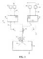
- FIG. 1is a diagram of the corona ignition system according to one embodiment of the invention showing alternate energy delivery paths A, B, and C;
- FIG. 2is a diagram of the system of FIG. 1 showing energy delivery path A;
- FIG. 3is a diagram of the system of FIG. 1 showing energy delivery path B;
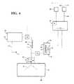
- FIG. 4is a diagram of the system of FIG. 1 showing energy delivery path C.
- One aspect of the inventionprovides a corona ignition system 20 for igniting a mixture of fuel and air of a combustion chamber 32 comprising a firing end assembly 22 , a corona drive circuit 26 , and an energy storage and delivery circuit, referred to as an energy circuit 28 .
- the firing end assembly 22comprises an igniter 24 including an electrode 30 projecting into a combustion chamber 32 .
- the corona drive circuit 26transmits energy to the electrode 30 in an amount capable of emitting an electrical discharge, typically corona discharge but maybe arc discharge, from the electrode 30 .
- the energy circuit 28is auxiliary to the corona drive circuit 26 and stores supplemental energy while the corona drive circuit 26 transmits energy to the electrode 30 . When arc discharge is detected, the energy circuit 28 then transmits the stored energy to the electrode 30 to intentionally maintain the arc discharge 29 .
- the stored energy transmitted to the electrode 30provides a robust arc discharge 29 , which accordingly provides reliable ignition.
- the igniter 24 of the firing end assembly 22is installed in a cylinder head of the engine (not shown), typically an internal combustion engine of an automotive vehicle, such as a hybrid vehicle, or a gas turbine engine.
- the electrode 30 of the igniter 24typically includes a firing tip for emitting the electrical field.
- the system 20includes a drive power supply 34 providing the energy to the corona drive circuit 26 and ultimately to the electrode 30 .
- the drive power supply 34is typically a 12 volt battery, but can be another power source.
- the corona ignition system 20is designed to provide energy to the electrode 30 at a predetermined time, duration, and voltage level such that the electrode 30 emits the electrical field, typically in the form of a corona discharge, and ignition occurs along the entire length of the electrical field.
- the predetermined time, duration and voltage levelmay be calculated or determined by an engine control unit (ECU) of the vehicle.
- the voltage levelis typically the highest voltage capable of providing a corona discharge without forming an arc discharge.
- the system 20includes a drive circuit controller 36 providing a drive control signal 38 to the corona drive circuit 26 , indicating the predetermined time, duration, and voltage level required to achieve corona discharge.
- the drive circuit controller 36can be integral with the ECU, or can be a separate unit.
- the corona drive circuit 26Upon receiving the energy from the drive power supply 34 , and receiving the drive control signal 38 from the drive circuit controller 36 , the corona drive circuit 26 manipulates the energy to output an AC current and to meet the predetermined time, duration, and voltage level required to achieve the corona discharge. The corona drive circuit 26 also manipulates the energy to match a particular resonance frequency, which will be discussed further below.
- the corona drive circuit 26is a high frequency oscillating circuit which may also include a transformer, referred to as a drive transformer 44 . The circuit 26 is used to manipulate the energy provided by the drive power supply 34 .
- the corona drive circuit 26then transmits the manipulated AC current of energy to a tuned or LC circuit 48 , as shown in FIG. 1 .
- the LC circuitis also referred to as an LC resonant circuit or LC resonator.
- the LC circuitis provided by a resonating inductor 46 and capacitance (C 1 ) of the firing end assembly 22 , as shown in FIG. 1 .
- the resonating inductor 46operates at a particular voltage (L 1 ) and is provided by a coil of metal, such as copper.
- the coilis referred to as the first coil 50 , and is coupled to the electrode 30 of the igniter 24 .
- the resonating inductor 46also operates at a resonance frequency.
- a feedback loop signal 52 from the LC circuit 48 to the corona drive circuit 26conveys the resonance frequency to the corona drive circuit 26 , and the corona drive circuit 26 manipulates the supplied energy to match the resonating frequency.
- the system 20can also include electrical connection and insulation components between the resonating inductor 46 and electrode 30 .
- the LC circuit 48Upon receiving the energy from the corona drive circuit 26 , the LC circuit 48 transforms the energy prior to transmitting it to the electrode 30 .
- the LC circuit 48typically amplifies the voltage and decreases the current. In one embodiment, the LC circuit 48 increases the energy to a voltage of up to 15,000 volts, typically 5,000 to 10,000 volts. The energy is then transmitted from the LC circuit 48 to the electrode 30 to provide the corona discharge.
- the resonancecauses a high voltage at the electrode 30 , and the electrode 30 emits the electrical field in the surrounding air of the combustion chamber 32 , preferably in the form of corona discharge, but possibly in the form of arc discharge.
- the predetermined voltage level provided to the electrode 30is typically the highest voltage that can provide a corona discharge without switching to an arc discharge.
- the electrical fieldignites the mixture of fuel and air in the combustion chamber 32 along the entire length of the electrical field. If the electrode is emitting the corona discharge and providing reliable ignition, the corona ignition system 20 may operate without employing the stored energy from the energy circuit 28 .
- supplemental energyis stored in the energy circuit 28 auxiliary to the corona drive circuit 26 at startup and simultaneously while the system 20 operates.
- the energy of the corona drive circuit 26is immediately depleted.
- the arc dischargeimmediately causes the small amount of energy stored in the LC resonator 48 to discharge.
- the arc dischargeremains for a short period of time, but not long enough to ensure reliable ignition.
- the energy stored in the energy circuit 28is immediately discharged into the system 20 and ultimately transmitted to the electrode 30 to intentionally maintain the arc discharge 29 .
- the stored energyis transmitted to the electrode 30 in an amount great enough to maintain the arc discharge 29 at a robust level and duration, and the intentionally maintained arc discharge 29 ignites the mixture of fuel and air in the combustion chamber 32 .
- an arc feedback signal 56is transmitted to a controller of the energy circuit 28 , referred to as an energy controller 58 .
- the energy controller 58receives the arc feedback signal 56 , then transmits an arc control signal 60 to the energy circuit 28 , initiating and instructing the energy circuit 28 to discharge the stored energy for transmission to the electrode 30 .
- the energy controller 58can be integrated with the ECU or the drive circuit controller 36 , or can be a separate unit.
- the energy circuit 28typically includes a capacitor, referred to as the energy capacitor 62 , for storing the additional energy.
- the energy capacitor 62stores energy in an amount much greater than the amount stored by the LC resonant circuit 48 or other capacitors typical used corona ignition systems 20 , typically 100 to 200 times greater. As stated above, the amount of energy stored in typical corona ignition systems 20 is not enough to initiate and maintain arc discharge once an arc discharge occurs.
- the corona ignition system 20includes a supplemental power supply, referred to as an energy power supply 68 , providing the extra energy to the energy capacitor 62 .
- the energy supplied to the energy circuit 28may be from the same supply as the corona drive circuit 26 .
- the extra energyis transmitted from the corona drive circuit 26 to the energy circuit 28 .
- the energy circuit 28Upon receiving the arc control signal 60 from the energy controller 58 , the energy circuit 28 transmits or discharges some or all of the storage energy, which is ultimately transmitted to the electrode 30 . Thus, upon detection of the arc discharge, the stored energy supply is immediately depleted. Once the stored energy is discharged, the energy circuit 28 is immediately reset and supplemental energy is again supplied to the energy circuit 28 . Accordingly, the system 20 is again ready to discharge stored energy to the electrode 30 upon the next occurrence of arc discharge and receipt of the arc control signal 60 .
- the corona ignition system 20can transmit the stored energy to the electrode 30 according to several different paths, for example paths A, B, and C.
- the energy initially discharged from the energy circuit 28is typically at a few hundred volts, which may not be great enough to initiate or maintain the arc discharge.
- the system 20may include another transformer, referred to as an energy transformer 70 , to increase the voltage of the energy prior to transmitting it to the electrode 30 .
- the energy transformer 70includes at least one coil of metal, referred to as a second coil 72 , electrically connected to the energy circuit 28 and electrically connected to at least one other component of the system 20 , either the LC circuit 48 or the electrode 30 .
- the energy transformer 70receives the stored energy from the energy circuit 28 and increases the voltage of the energy before transmitting it ultimately to the electrode 30 .
- the energy transformer 70may also be used to block energy from transmitting between the electrode 30 and the energy circuit 28 and to prevent damage to the circuits 26 , 28 , 48 .
- the energy transformer 70is integrated with the drive transformer 44 of the corona drive circuit 26 .
- the energy transformer 70is integrated with the resonating inductor 46 of the LC circuit 48 .
- a very high voltageis stored in the energy capacitor 62 of the energy circuit 28 , and thus the energy transformer 70 is not necessary.
- the stored energyis discharged from the energy circuit 28 and transmitted to the electrode 30 over a predetermined period of time, rather than discharged instantaneously.
- the predetermined period of timereferred to as a time constant is approximately one millisecond.
- the time constantcan be quantified by comparing it to the voltage (L 1 ) of the resonating inductor 46 and the capacitance (C 1 ) of the firing end assembly 22 .
- the time constantmust be longer than L 1 /C 1 , typically 100 to 2000 times longer.
- the energy circuit 28 , energy transformer 70 , and LC circuit 48are programmed to meet the predetermined time constant.
- At least one blocking element 74may be used to block energy from transmitting to and from or between the electrode 30 , the corona drive circuit 26 , the energy circuit 28 , and other components of the system 20 during predetermined periods of time.
- the blocking elements 74may also be designed to promote energy transmission between components of the system 20 .
- the blocking elements 74are passive, for example a filter consisting of resistive and reactive components.
- the blocking elements 74include linear passive elements, for example diodes, TVS, or spark gap units.
- the blocking elements 74are fully active, for example a transistor.
- the blocking elements 74are used to transmit energy from the corona drive circuit 26 to the energy capacitor 62 .
- the design of the blocking elements 74 and their implementationdepends on the specific requirements of the corona ignition system 20 and application of the system 20 .
- FIG. 2illustrates one exemplary embodiment, wherein the energy circuit 28 transmits the stored energy along path A to the electrode 30 .
- the energy transformer 70is disposed between the energy circuit 28 and the resonating inductor 46 of the LC circuit 48 .
- the stored energyis transmitted from the energy circuit 28 through the energy transformer 70 , then through the resonating inductor 46 of the LC circuit 48 and finally to the electrode 30 .
- the energy transformer 70increases the voltage of the stored energy, prior to transmitting the stored energy to the LC circuit 48 .
- FIG. 1illustrates one exemplary embodiment, wherein the energy circuit 28 transmits the stored energy along path A to the electrode 30 .
- the energy transformer 70is disposed between the energy circuit 28 and the resonating inductor 46 of the LC circuit 48 .
- the stored energyis transmitted from the energy circuit 28 through the energy transformer 70 , then through the resonating inductor 46 of the LC circuit 48 and finally to the electrode 30 .
- the energy transformer 70increases the voltage of the
- the energy circuit 28 , energy transformer 70 , and blocking elements 74are programmed to deliver the stored energy according to the time constant to achieve the robust arc discharge 29 .
- FIG. 3illustrates another exemplary embodiment, wherein the energy circuit 28 transmits the stored energy along path B to the electrode 30 and the energy transformer 70 is integral with the LC circuit 48 .
- This exemplary embodimentis often preferred over the embodiments of FIGS. 2 and 4 for its simpler construction and thus lower cost.
- the integrated energy transformer 70is formed by magnetically coupling the first coil 50 of the resonating inductor 46 with a second coil 72 . A few turns of the second coil 72 are wound onto the same magnetic core as the first coil 50 of the resonating inductor 46 , but the second coil 72 is electrically isolated from the first coil 50 .
- the stored energyis transmitted from the energy circuit 28 through the integrated energy transformer 70 and LC circuit 48 and finally to the electrode 30 .
- the integrated energy transformer 70increases the voltage of the stored energy, prior to transmitting the stored energy to the electrode 30 .
- the embodiment of FIG. 3also includes one blocking element 74 between the integrated energy transformer 70 and the LC circuit 48 .
- This blocking element 74may prevent the energy circuit 28 from “bleeding” energy from the electrode 30 , such as energy from the corona discharge when arc discharge has not yet occurred. Alternatively, the blocking element 74 may transmit any bled energy back to the energy capacitor 62 of the energy circuit 28 .
- the energy circuit 28 , transformer, and blocking elements 74are programmed to deliver the stored energy according to the time constant and over the predetermine period to achieve the robust arc discharge.
- FIG. 4illustrates another exemplary embodiment, wherein the energy circuit 28 transmits the stored energy along path C to the electrode 30 .
- the energy transformer 70is auxiliary to the resonating inductor 46 of the LC circuit 48 and is disposed between the energy circuit 28 and the electrode 30 .
- the energyis transmitted from the energy circuit 28 directly to the electrode 30 , and does not pass through the LC circuit 48 .
- the embodiment of FIG. 4also includes one blocking element 74 between the energy transformer 70 and the LC circuit 48 to prevent energy from transmitting from the electrode 30 to back to the circuits 26 , 28 , 48 , such as from the corona discharge, before arc discharge has occurred.
- Another one of the blocking elements 74is located between the corona drive circuit 26 and the LC circuit 48 to prevent energy from transmitting from the electrode 30 back to the corona drive circuit 26 and to allow energy transmission through the LC circuit 48 .
- the energy circuit 28 , energy transformer 70 , and blocking elements 74are programmed to deliver the stored energy over the predetermine period of time to achieve the robust arc discharge.
- Another aspect of the inventionprovides a method for igniting a mixture of fuel and air of an combustion chamber.
- the methodincludes supplying energy and drive control signals 38 to the corona drive circuit 26 while also supplying energy to the energy circuit 28 .
- the methodthen includes transmitting energy from the corona drive circuit 26 to the electrode 30 in an amount capable of emitting the electrical discharge from the electrode 30 .
- the step of transmitting energy from the corona drive circuit 26 to the electrode 30includes determining and transmitting a predetermine amount of energy, wherein the predetermined amount of energy is capable of emitting a corona discharge and avoiding an arc discharge.
- the methodincludes supplying and storing energy in the energy circuit 28 auxiliary to the corona drive circuit 26 .
- the step of storing energy in the energy circuit 28typically includes charging the energy capacitor 62 of the energy circuit 28 .
- the storing energy stepincludes transmitting energy from the corona drive circuit 26 to the energy circuit 28 .
- the methodalso includes detecting an arc discharge emitting from the electrode 30 . Once the onset of arc discharge is detected, the method includes transmitting the arc feedback signal 56 to the energy controller 58 , and then transmitting the arc control signal 60 from the energy controller 58 to the energy circuit 28 .
- the arc control signal 60initiates the step of transmitting or discharging the stored energy from the energy circuit 28 to the electrode 30 and thus intentionally maintaining an arc discharge 29 .
- the methodincludes recharging the energy capacitor 62 of the energy circuit 28 .
- the methodincludes maintaining energy in the energy circuit 28 in a sufficient amount, which is an amount capable of intentionally maintaining an arc discharge 29 .
- the system 20is immediately ready for the next occurrence of arc discharge.
- the methodincludes transmitting the stored energy to the electrode 30 according to the time constant, over a predetermined period of time.
- the methodincludes calculating the predetermined period of time, or time constant, and conveying the time constant to the energy circuit 28 in the arc control signal 60 .
- the methodtypically includes increasing the voltage of the stored energy by the energy transformer 70 , prior to transmitting the stored energy to the electrode 30 .
- the methodincludes using the blocking elements 74 for preventing or allowing energy from transmitting to and from or between the electrode 30 , the corona drive circuit 26 , the energy circuit 28 , or other components of the system 20 during predetermined periods of time, such as while transmitting the stored energy from the energy circuit 28 to the electrode 30 .
Landscapes
- Engineering & Computer Science (AREA)
- Chemical & Material Sciences (AREA)
- Combustion & Propulsion (AREA)
- Mechanical Engineering (AREA)
- General Engineering & Computer Science (AREA)
- Physics & Mathematics (AREA)
- Optics & Photonics (AREA)
- Plasma & Fusion (AREA)
- Ignition Installations For Internal Combustion Engines (AREA)
- Spark Plugs (AREA)
Abstract
Description
| ELEMENT LIST |
| Element | Element Name | |
| 20 | ||
| 22 | firing | |
| 24 | ||
| 26 | ||
| 28 | ||
| 29 | corona or | |
| 30 | ||
| 32 | ||
| 34 | ||
| 36 | ||
| 38 | ||
| 44 | ||
| 46 | resonating | |
| 48 | ||
| 50 | ||
| 52 | ||
| 56 | ||
| 58 | ||
| 60 | ||
| 62 | ||
| 68 | ||
| 70 | ||
| 72 | ||
| 74 | blocking element | |
Claims (20)
Priority Applications (1)
| Application Number | Priority Date | Filing Date | Title |
|---|---|---|---|
| US13/222,616US8749945B2 (en) | 2010-08-31 | 2011-08-31 | Electrical arrangement of hybrid ignition device |
Applications Claiming Priority (2)
| Application Number | Priority Date | Filing Date | Title |
|---|---|---|---|
| US37867310P | 2010-08-31 | 2010-08-31 | |
| US13/222,616US8749945B2 (en) | 2010-08-31 | 2011-08-31 | Electrical arrangement of hybrid ignition device |
Publications (2)
| Publication Number | Publication Date |
|---|---|
| US20120063054A1 US20120063054A1 (en) | 2012-03-15 |
| US8749945B2true US8749945B2 (en) | 2014-06-10 |
Family
ID=44645231
Family Applications (1)
| Application Number | Title | Priority Date | Filing Date |
|---|---|---|---|
| US13/222,616Active2032-02-21US8749945B2 (en) | 2010-08-31 | 2011-08-31 | Electrical arrangement of hybrid ignition device |
Country Status (6)
| Country | Link |
|---|---|
| US (1) | US8749945B2 (en) |
| EP (1) | EP2612020B1 (en) |
| JP (1) | JP5795069B2 (en) |
| KR (1) | KR101826303B1 (en) |
| CN (1) | CN103109078B (en) |
| WO (1) | WO2012030934A2 (en) |
Cited By (1)
| Publication number | Priority date | Publication date | Assignee | Title |
|---|---|---|---|---|
| US9514917B1 (en)* | 2013-08-29 | 2016-12-06 | The Boeing Company | Controlled-energy electrical arc systems, methods, and apparatuses |
Families Citing this family (10)
| Publication number | Priority date | Publication date | Assignee | Title |
|---|---|---|---|---|
| DE102010055568B3 (en)* | 2010-12-21 | 2012-06-21 | Borgwarner Beru Systems Gmbh | Method for igniting fuel by means of a corona discharge |
| EP2935866B8 (en)* | 2012-12-21 | 2019-05-22 | Federal-Mogul Ignition LLC | Intra-event control strategy for corona ignition systems |
| US9341610B1 (en) | 2013-08-29 | 2016-05-17 | The Boeing Company | Electrical arc trigger systems, methods, and apparatuses |
| DE102013111806B3 (en)* | 2013-10-25 | 2015-01-15 | Borgwarner Beru Systems Gmbh | Method for controlling a corona ignition device and corona ignition device |
| EP3080436B1 (en) | 2013-12-12 | 2023-11-08 | Federal-Mogul Ignition LLC | Method for resonant frequency detection in corona ignition systems |
| JP6445928B2 (en)* | 2015-05-19 | 2018-12-26 | 本田技研工業株式会社 | Ignition device for internal combustion engine |
| US10330225B2 (en)* | 2017-01-28 | 2019-06-25 | Mark Eugene Goodson | Lightning resistant gas tubing system |
| DE102017214177B3 (en) | 2017-08-15 | 2019-01-31 | MULTITORCH Services GmbH | Device for igniting fuel by means of corona discharges |
| JP6723477B2 (en)* | 2017-11-09 | 2020-07-15 | 三菱電機株式会社 | Ignition device |
| KR102243322B1 (en) | 2020-08-14 | 2021-04-21 | 김덕철 | High voltage igniter |
Citations (18)
| Publication number | Priority date | Publication date | Assignee | Title |
|---|---|---|---|---|
| US3974412A (en) | 1975-02-03 | 1976-08-10 | Massachusetts Institute Of Technology | Spark plug employing both corona discharge and arc discharge and a system employing the same |
| US4369758A (en) | 1980-09-18 | 1983-01-25 | Nissan Motor Company, Limited | Plasma ignition system |
| US5471362A (en) | 1993-02-26 | 1995-11-28 | Frederick Cowan & Company, Inc. | Corona arc circuit |
| US5568801A (en) | 1994-05-20 | 1996-10-29 | Ortech Corporation | Plasma arc ignition system |
| US5654868A (en) | 1995-10-27 | 1997-08-05 | Sl Aburn, Inc. | Solid-state exciter circuit with two drive pulses having indendently adjustable durations |
| US5727534A (en) | 1994-12-12 | 1998-03-17 | Ngk Spark Plug Co., Ltd. | Misfire detecting device for multi-cylinder internal combustion engine |
| US5777216A (en) | 1996-02-01 | 1998-07-07 | Adrenaline Research, Inc. | Ignition system with ionization detection |
| US6553981B1 (en) | 1999-06-16 | 2003-04-29 | Knite, Inc. | Dual-mode ignition system utilizing traveling spark ignitor |
| WO2004047146A2 (en) | 2002-11-15 | 2004-06-03 | Cowan Thomas L | Igniter circuit with an air gap |
| US6883507B2 (en) | 2003-01-06 | 2005-04-26 | Etatech, Inc. | System and method for generating and sustaining a corona electric discharge for igniting a combustible gaseous mixture |
| US20060165429A1 (en)* | 2004-11-30 | 2006-07-27 | Masahiko Satoh | Image forming apparatus, fixing unit having a selectively controlled power supply and associated methodology |
| US7095181B2 (en) | 1995-07-14 | 2006-08-22 | Unsion Industries | Method and apparatus for controllably generating sparks in an ignition system or the like |
| US7323213B2 (en)* | 1998-05-08 | 2008-01-29 | Mitsubishi Denki Kabushiki Kaisha | Apparatus and method for discharge surface treatment |
| US7594958B2 (en) | 2002-07-03 | 2009-09-29 | Kronos Advanced Technologies, Inc. | Spark management method and device |
| WO2010011838A1 (en) | 2008-07-23 | 2010-01-28 | Borgwarner, Inc. | Igniting combustible mixtures |
| EP2187044A1 (en) | 2008-01-08 | 2010-05-19 | NGK Spark Plug Co., Ltd. | Plasma jet ignition plug ignition control |
| US20100147239A1 (en) | 2008-12-16 | 2010-06-17 | Hang Lu | Ignition arrangement |
| US20110197865A1 (en)* | 2010-02-12 | 2011-08-18 | Keith Hampton | Intentional arcing of a corona igniter |
Family Cites Families (4)
| Publication number | Priority date | Publication date | Assignee | Title |
|---|---|---|---|---|
| JPS61294167A (en)* | 1985-06-24 | 1986-12-24 | Nippon Denso Co Ltd | Ignitor for internal-combustion engine |
| JP2002327672A (en)* | 2001-04-27 | 2002-11-15 | Denso Corp | Ignition device of internal combustion engine |
| EP2093416B1 (en)* | 2006-05-18 | 2013-09-04 | North-West University | Ignition system |
| CN101351638B (en)* | 2006-09-20 | 2012-09-26 | 创想科学技术工程株式会社 | Ignition devices, internal combustion engines, glow plugs, plasma equipment, exhaust gas degradation devices, ozone generation/disinfection/sterilization devices, and deodorization devices |
- 2011
- 2011-08-31WOPCT/US2011/049924patent/WO2012030934A2/enactiveApplication Filing
- 2011-08-31JPJP2013527256Apatent/JP5795069B2/ennot_activeExpired - Fee Related
- 2011-08-31USUS13/222,616patent/US8749945B2/enactiveActive
- 2011-08-31CNCN201180044674.6Apatent/CN103109078B/ennot_activeExpired - Fee Related
- 2011-08-31EPEP11755207.5Apatent/EP2612020B1/ennot_activeNot-in-force
- 2011-08-31KRKR1020137005175Apatent/KR101826303B1/ennot_activeExpired - Fee Related
Patent Citations (19)
| Publication number | Priority date | Publication date | Assignee | Title |
|---|---|---|---|---|
| US3974412A (en) | 1975-02-03 | 1976-08-10 | Massachusetts Institute Of Technology | Spark plug employing both corona discharge and arc discharge and a system employing the same |
| US4369758A (en) | 1980-09-18 | 1983-01-25 | Nissan Motor Company, Limited | Plasma ignition system |
| US5471362A (en) | 1993-02-26 | 1995-11-28 | Frederick Cowan & Company, Inc. | Corona arc circuit |
| US5568801A (en) | 1994-05-20 | 1996-10-29 | Ortech Corporation | Plasma arc ignition system |
| US5727534A (en) | 1994-12-12 | 1998-03-17 | Ngk Spark Plug Co., Ltd. | Misfire detecting device for multi-cylinder internal combustion engine |
| US7095181B2 (en) | 1995-07-14 | 2006-08-22 | Unsion Industries | Method and apparatus for controllably generating sparks in an ignition system or the like |
| US5654868A (en) | 1995-10-27 | 1997-08-05 | Sl Aburn, Inc. | Solid-state exciter circuit with two drive pulses having indendently adjustable durations |
| US5777216A (en) | 1996-02-01 | 1998-07-07 | Adrenaline Research, Inc. | Ignition system with ionization detection |
| US7323213B2 (en)* | 1998-05-08 | 2008-01-29 | Mitsubishi Denki Kabushiki Kaisha | Apparatus and method for discharge surface treatment |
| US6553981B1 (en) | 1999-06-16 | 2003-04-29 | Knite, Inc. | Dual-mode ignition system utilizing traveling spark ignitor |
| US7594958B2 (en) | 2002-07-03 | 2009-09-29 | Kronos Advanced Technologies, Inc. | Spark management method and device |
| WO2004047146A2 (en) | 2002-11-15 | 2004-06-03 | Cowan Thomas L | Igniter circuit with an air gap |
| US6883507B2 (en) | 2003-01-06 | 2005-04-26 | Etatech, Inc. | System and method for generating and sustaining a corona electric discharge for igniting a combustible gaseous mixture |
| US20060165429A1 (en)* | 2004-11-30 | 2006-07-27 | Masahiko Satoh | Image forming apparatus, fixing unit having a selectively controlled power supply and associated methodology |
| EP2187044A1 (en) | 2008-01-08 | 2010-05-19 | NGK Spark Plug Co., Ltd. | Plasma jet ignition plug ignition control |
| WO2010011838A1 (en) | 2008-07-23 | 2010-01-28 | Borgwarner, Inc. | Igniting combustible mixtures |
| US20100147239A1 (en) | 2008-12-16 | 2010-06-17 | Hang Lu | Ignition arrangement |
| EP2199597A2 (en) | 2008-12-16 | 2010-06-23 | GE Jenbacher GmbH & Co OHG | Ignition device for a combustion engine, which supplies a corona discharge |
| US20110197865A1 (en)* | 2010-02-12 | 2011-08-18 | Keith Hampton | Intentional arcing of a corona igniter |
Non-Patent Citations (1)
| Title |
|---|
| International Search Report PCT/US2011/049924 mailed on Mar. 28, 2012. |
Cited By (1)
| Publication number | Priority date | Publication date | Assignee | Title |
|---|---|---|---|---|
| US9514917B1 (en)* | 2013-08-29 | 2016-12-06 | The Boeing Company | Controlled-energy electrical arc systems, methods, and apparatuses |
Also Published As
| Publication number | Publication date |
|---|---|
| KR101826303B1 (en) | 2018-02-06 |
| EP2612020B1 (en) | 2015-06-10 |
| JP2013539519A (en) | 2013-10-24 |
| US20120063054A1 (en) | 2012-03-15 |
| EP2612020A2 (en) | 2013-07-10 |
| CN103109078A (en) | 2013-05-15 |
| CN103109078B (en) | 2015-06-17 |
| WO2012030934A3 (en) | 2012-05-10 |
| JP5795069B2 (en) | 2015-10-14 |
| WO2012030934A2 (en) | 2012-03-08 |
| KR20130140626A (en) | 2013-12-24 |
Similar Documents
| Publication | Publication Date | Title |
|---|---|---|
| US8749945B2 (en) | Electrical arrangement of hybrid ignition device | |
| US8760067B2 (en) | System and method for controlling arc formation in a corona discharge ignition system | |
| US20120145136A1 (en) | Multi-event corona discharge ignition assembly and method of control and operation | |
| US8528532B2 (en) | Optimum control of the resonant frequency of a resonator in a radiofrequency ignition system | |
| US8726871B2 (en) | Corona ignition system having selective enhanced arc formation | |
| US8555867B2 (en) | Energy efficient plasma generation | |
| US20160013623A1 (en) | Active-control resonant ignition system | |
| US10167839B2 (en) | Ignition control device and ignition control method for internal combustion engine | |
| US9422912B2 (en) | Method for controlling a corona ignition device | |
| US20050134281A1 (en) | Device to provide a regulated power supply for in-cylinder ionization detection by using the ignition coil fly back energy and two-stage regulation | |
| EP2534369A2 (en) | Intentional arcing of a corona igniter | |
| WO2019198119A1 (en) | Ignition device for internal combustion engine | |
| US10344733B2 (en) | Internal combustion engine ignition apparatus | |
| JPWO2019130462A1 (en) | Ignition system for internal combustion engine | |
| JP2023135718A (en) | Ignition device |
Legal Events
| Date | Code | Title | Description |
|---|---|---|---|
| AS | Assignment | Owner name:FEDERAL-MOGUL IGNITION, MICHIGAN Free format text:ASSIGNMENT OF ASSIGNORS INTEREST;ASSIGNORS:BURROWS, JOHN ANTONY;LYKOWSKI, JAMES D.;SIGNING DATES FROM 20111026 TO 20111101;REEL/FRAME:027220/0957 | |
| STCF | Information on status: patent grant | Free format text:PATENTED CASE | |
| AS | Assignment | Owner name:CITIBANK, N.A., AS COLLATERAL TRUSTEE, DELAWARE Free format text:SECURITY INTEREST;ASSIGNORS:FEDERAL-MOGUL CORPORATION, A DELAWARE CORPORATION;FEDERAL-MOGUL WORLD WIDE, INC., A MICHIGAN CORPORATION;FEDERAL-MOGUL IGNITION COMPANY, A DELAWARE CORPORATION;AND OTHERS;REEL/FRAME:033204/0707 Effective date:20140616 | |
| AS | Assignment | Owner name:CITIBANK, N.A., AS COLLATERAL TRUSTEE, NEW YORK Free format text:GRANT OF SECURITY INTEREST IN UNITED STATES PATENTS;ASSIGNORS:FEDERAL-MOGUL LLC;FEDERAL-MOGUL PRODUCTS, INC.;FEDERAL-MOGUL MOTORPARTS CORPORATION;AND OTHERS;REEL/FRAME:042963/0662 Effective date:20170330 | |
| AS | Assignment | Owner name:CITIBANK, N.A., AS COLLATERAL TRUSTEE, NEW YORK Free format text:GRANT OF SECURITY INTEREST IN UNITED STATES PATENTS;ASSIGNORS:FEDERAL-MOGUL LLC;FEDERAL-MOGUL PRODUCTS, INC.;FEDERAL-MOGUL MOTORPARTS LLC;AND OTHERS;REEL/FRAME:044013/0419 Effective date:20170629 | |
| MAFP | Maintenance fee payment | Free format text:PAYMENT OF MAINTENANCE FEE, 4TH YEAR, LARGE ENTITY (ORIGINAL EVENT CODE: M1551) Year of fee payment:4 | |
| AS | Assignment | Owner name:BANK OF AMERICA, N.A., AS COLLATERAL TRUSTEE, MICHIGAN Free format text:COLLATERAL TRUSTEE RESIGNATION AND APPOINTMENT AGREEMENT;ASSIGNOR:CITIBANK, N.A., AS COLLATERAL TRUSTEE;REEL/FRAME:045822/0765 Effective date:20180223 Owner name:BANK OF AMERICA, N.A., AS COLLATERAL TRUSTEE, MICH Free format text:COLLATERAL TRUSTEE RESIGNATION AND APPOINTMENT AGREEMENT;ASSIGNOR:CITIBANK, N.A., AS COLLATERAL TRUSTEE;REEL/FRAME:045822/0765 Effective date:20180223 | |
| AS | Assignment | Owner name:WILMINGTON TRUST, NATIONAL ASSOCIATION, AS COLLATERAL TRUSTEE, MINNESOTA Free format text:CONFIRMATORY GRANT OF SECURITY INTERESTS IN UNITED STATES PATENTS;ASSIGNORS:TENNECO INC.;TENNECO AUTOMOTIVE OPERATING COMPANY INC.;TENNECO INTERNATIONAL HOLDING CORP.;AND OTHERS;REEL/FRAME:047223/0001 Effective date:20181001 Owner name:WILMINGTON TRUST, NATIONAL ASSOCIATION, AS COLLATE Free format text:CONFIRMATORY GRANT OF SECURITY INTERESTS IN UNITED STATES PATENTS;ASSIGNORS:TENNECO INC.;TENNECO AUTOMOTIVE OPERATING COMPANY INC.;TENNECO INTERNATIONAL HOLDING CORP.;AND OTHERS;REEL/FRAME:047223/0001 Effective date:20181001 | |
| AS | Assignment | Owner name:FEDERAL-MOGUL LLC, MICHIGAN Free format text:RELEASE BY SECURED PARTY;ASSIGNOR:BANK OF AMERICA, N.A., AS COLLATERAL TRUSTEE;REEL/FRAME:047276/0554 Effective date:20181001 Owner name:FEDERAL MOGUL POWERTRAIN LLC, MICHIGAN Free format text:RELEASE BY SECURED PARTY;ASSIGNOR:BANK OF AMERICA, N.A., AS COLLATERAL TRUSTEE;REEL/FRAME:047276/0554 Effective date:20181001 Owner name:FEDERAL-MOGUL MOTORPARTS LLC, MICHIGAN Free format text:RELEASE BY SECURED PARTY;ASSIGNOR:BANK OF AMERICA, N.A., AS COLLATERAL TRUSTEE;REEL/FRAME:047276/0554 Effective date:20181001 Owner name:FEDERAL-MOGUL WORLD WIDE LLC, MICHIGAN Free format text:RELEASE BY SECURED PARTY;ASSIGNOR:BANK OF AMERICA, N.A., AS COLLATERAL TRUSTEE;REEL/FRAME:047276/0554 Effective date:20181001 Owner name:FEDERAL-MOGUL PRODUCTS, INC., MICHIGAN Free format text:RELEASE BY SECURED PARTY;ASSIGNOR:BANK OF AMERICA, N.A., AS COLLATERAL TRUSTEE;REEL/FRAME:047276/0554 Effective date:20181001 Owner name:FEDERAL-MOGUL CHASSIS LLC, MICHIGAN Free format text:RELEASE BY SECURED PARTY;ASSIGNOR:BANK OF AMERICA, N.A., AS COLLATERAL TRUSTEE;REEL/FRAME:047276/0554 Effective date:20181001 Owner name:FEDERAL-MOGUL IGNITION COMPANY, MICHIGAN Free format text:RELEASE BY SECURED PARTY;ASSIGNOR:BANK OF AMERICA, N.A., AS COLLATERAL TRUSTEE;REEL/FRAME:047276/0554 Effective date:20181001 Owner name:FEDERAL-MOGUL LLC, MICHIGAN Free format text:RELEASE BY SECURED PARTY;ASSIGNOR:BANK OF AMERICA, N.A., AS COLLATERAL TRUSTEE;REEL/FRAME:047276/0771 Effective date:20181001 Owner name:FEDERAL MOGUL POWERTRAIN LLC, MICHIGAN Free format text:RELEASE BY SECURED PARTY;ASSIGNOR:BANK OF AMERICA, N.A., AS COLLATERAL TRUSTEE;REEL/FRAME:047276/0771 Effective date:20181001 Owner name:FEDERAL-MOGUL MOTORPARTS LLC, MICHIGAN Free format text:RELEASE BY SECURED PARTY;ASSIGNOR:BANK OF AMERICA, N.A., AS COLLATERAL TRUSTEE;REEL/FRAME:047276/0771 Effective date:20181001 Owner name:FEDERAL-MOGUL IGNITION COMPANY, MICHIGAN Free format text:RELEASE BY SECURED PARTY;ASSIGNOR:BANK OF AMERICA, N.A., AS COLLATERAL TRUSTEE;REEL/FRAME:047276/0771 Effective date:20181001 Owner name:FEDERAL-MOGUL WORLD WIDE LLC, MICHIGAN Free format text:RELEASE BY SECURED PARTY;ASSIGNOR:BANK OF AMERICA, N.A., AS COLLATERAL TRUSTEE;REEL/FRAME:047276/0771 Effective date:20181001 Owner name:FEDERAL-MOGUL PRODUCTS, INC., MICHIGAN Free format text:RELEASE BY SECURED PARTY;ASSIGNOR:BANK OF AMERICA, N.A., AS COLLATERAL TRUSTEE;REEL/FRAME:047276/0771 Effective date:20181001 Owner name:FEDERAL-MOGUL CHASSIS LLC, MICHIGAN Free format text:RELEASE BY SECURED PARTY;ASSIGNOR:BANK OF AMERICA, N.A., AS COLLATERAL TRUSTEE;REEL/FRAME:047276/0771 Effective date:20181001 | |
| AS | Assignment | Owner name:WILMINGTON TRUST, NATIONAL ASSOCIATION, AS CO-COLLATERAL TRUSTEE, SUCCESSOR COLLATERAL TRUSTEE, MINNESOTA Free format text:COLLATERAL TRUSTEE RESIGNATION AND APPOINTMENT, JOINDER, ASSUMPTION AND DESIGNATION AGREEMENT;ASSIGNOR:BANK OF AMERICA, N.A., AS CO-COLLATERAL TRUSTEE AND RESIGNING COLLATERAL TRUSTEE;REEL/FRAME:047630/0661 Effective date:20181001 Owner name:WILMINGTON TRUST, NATIONAL ASSOCIATION, AS CO-COLL Free format text:COLLATERAL TRUSTEE RESIGNATION AND APPOINTMENT, JOINDER, ASSUMPTION AND DESIGNATION AGREEMENT;ASSIGNOR:BANK OF AMERICA, N.A., AS CO-COLLATERAL TRUSTEE AND RESIGNING COLLATERAL TRUSTEE;REEL/FRAME:047630/0661 Effective date:20181001 | |
| AS | Assignment | Owner name:FEDERAL-MOGUL IGNITION LLC, UNITED STATES Free format text:ASSIGNMENT OF ASSIGNORS INTEREST;ASSIGNOR:FEDERAL-MOGUL IGNITION COMPANY;REEL/FRAME:049821/0536 Effective date:20180731 | |
| AS | Assignment | Owner name:WILMINGTON TRUST, NATIONAL ASSOCIATION, MINNESOTA Free format text:SECURITY AGREEMENT;ASSIGNORS:TENNECO INC.;THE PULLMAN COMPANY;FEDERAL-MOGUL IGNITION LLC;AND OTHERS;REEL/FRAME:054555/0592 Effective date:20201130 | |
| AS | Assignment | Owner name:WILMINGTON TRUST, NATIONAL ASSOCIATION, MINNESOTA Free format text:SECURITY AGREEMENT;ASSIGNORS:TENNECO INC.;TENNECO AUTOMOTIVE OPERATING COMPANY INC.;THE PULLMAN COMPANY;AND OTHERS;REEL/FRAME:055626/0065 Effective date:20210317 | |
| AS | Assignment | Owner name:DRIV AUTOMOTIVE INC., ILLINOIS Free format text:RELEASE BY SECURED PARTY;ASSIGNOR:WILMINGTON TRUST, NATIONAL ASSOCIATION;REEL/FRAME:058392/0274 Effective date:20210317 Owner name:FEDERAL-MOGUL POWERTRAIN LLC, MICHIGAN Free format text:RELEASE BY SECURED PARTY;ASSIGNOR:WILMINGTON TRUST, NATIONAL ASSOCIATION;REEL/FRAME:058392/0274 Effective date:20210317 Owner name:FEDERAL-MOGUL CHASSIS LLC, MICHIGAN Free format text:RELEASE BY SECURED PARTY;ASSIGNOR:WILMINGTON TRUST, NATIONAL ASSOCIATION;REEL/FRAME:058392/0274 Effective date:20210317 Owner name:TENNECO INC., AS SUCCESSOR TO FEDERAL-MOGUL LLC, ILLINOIS Free format text:RELEASE BY SECURED PARTY;ASSIGNOR:WILMINGTON TRUST, NATIONAL ASSOCIATION;REEL/FRAME:058392/0274 Effective date:20210317 Owner name:FEDERAL-MOGUL IGNITION, LLC, AS SUCCESSOR TO FEDERAL-MOGUL IGNITION COMPANY, MICHIGAN Free format text:RELEASE BY SECURED PARTY;ASSIGNOR:WILMINGTON TRUST, NATIONAL ASSOCIATION;REEL/FRAME:058392/0274 Effective date:20210317 Owner name:FEDERAL-MOGUL MOTORPARTS LLC, AS SUCCESSOR TO FEDERAL-MOGUL MOTORPARTS CORPORATION, MICHIGAN Free format text:RELEASE BY SECURED PARTY;ASSIGNOR:WILMINGTON TRUST, NATIONAL ASSOCIATION;REEL/FRAME:058392/0274 Effective date:20210317 Owner name:FEDERAL-MOGUL WORLD WIDE, INC., AS SUCCESSOR TO FEDERAL-MOGUL WORLD WIDE LLC, MICHIGAN Free format text:RELEASE BY SECURED PARTY;ASSIGNOR:WILMINGTON TRUST, NATIONAL ASSOCIATION;REEL/FRAME:058392/0274 Effective date:20210317 Owner name:FEDERAL-MOGUL PRODUCTS US, LLC, AS SUCCESSOR TO FEDERAL-MOGUL PRODUCTS, INC., MICHIGAN Free format text:RELEASE BY SECURED PARTY;ASSIGNOR:WILMINGTON TRUST, NATIONAL ASSOCIATION;REEL/FRAME:058392/0274 Effective date:20210317 Owner name:FEDERAL-MOGUL PRODUCTS US, LLC, AS SUCCESSOR TO FEDERAL-MOGUL PRODUCTS, INC., MICHIGAN Free format text:RELEASE BY SECURED PARTY;ASSIGNOR:WILMINGTON TRUST, NATIONAL ASSOCIATION;REEL/FRAME:056886/0455 Effective date:20210317 Owner name:FEDERAL-MOGUL WORLD WIDE, INC., AS SUCCESSOR TO FEDERAL-MOGUL WORLD WIDE LLC, MICHIGAN Free format text:RELEASE BY SECURED PARTY;ASSIGNOR:WILMINGTON TRUST, NATIONAL ASSOCIATION;REEL/FRAME:056886/0455 Effective date:20210317 Owner name:FEDERAL-MOGUL MOTORPARTS LLC, AS SUCCESSOR TO FEDERAL-MOGUL MOTORPARTS CORPORATION, MICHIGAN Free format text:RELEASE BY SECURED PARTY;ASSIGNOR:WILMINGTON TRUST, NATIONAL ASSOCIATION;REEL/FRAME:056886/0455 Effective date:20210317 Owner name:FEDERAL-MOGUL IGNITION, LLC, AS SUCCESSOR TO FEDERAL-MOGUL IGNITION COMPANY, MICHIGAN Free format text:RELEASE BY SECURED PARTY;ASSIGNOR:WILMINGTON TRUST, NATIONAL ASSOCIATION;REEL/FRAME:056886/0455 Effective date:20210317 Owner name:TENNECO INC., AS SUCCESSOR TO FEDERAL-MOGUL LLC, ILLINOIS Free format text:RELEASE BY SECURED PARTY;ASSIGNOR:WILMINGTON TRUST, NATIONAL ASSOCIATION;REEL/FRAME:056886/0455 Effective date:20210317 Owner name:FEDERAL-MOGUL CHASSIS LLC, MICHIGAN Free format text:RELEASE BY SECURED PARTY;ASSIGNOR:WILMINGTON TRUST, NATIONAL ASSOCIATION;REEL/FRAME:056886/0455 Effective date:20210317 Owner name:FEDERAL-MOGUL POWERTRAIN LLC, MICHIGAN Free format text:RELEASE BY SECURED PARTY;ASSIGNOR:WILMINGTON TRUST, NATIONAL ASSOCIATION;REEL/FRAME:056886/0455 Effective date:20210317 Owner name:DRIV AUTOMOTIVE INC., ILLINOIS Free format text:RELEASE BY SECURED PARTY;ASSIGNOR:WILMINGTON TRUST, NATIONAL ASSOCIATION;REEL/FRAME:056886/0455 Effective date:20210317 | |
| MAFP | Maintenance fee payment | Free format text:PAYMENT OF MAINTENANCE FEE, 8TH YEAR, LARGE ENTITY (ORIGINAL EVENT CODE: M1552); ENTITY STATUS OF PATENT OWNER: LARGE ENTITY Year of fee payment:8 | |
| AS | Assignment | Owner name:FEDERAL-MOGUL PRODUCTS US LLC, MICHIGAN Free format text:RELEASE BY SECURED PARTY;ASSIGNOR:WILMINGTON TRUST, NATIONAL ASSOCIATION;REEL/FRAME:061975/0218 Effective date:20221117 Owner name:FEDERAL-MOGUL FINANCING CORPORATION, MICHIGAN Free format text:RELEASE BY SECURED PARTY;ASSIGNOR:WILMINGTON TRUST, NATIONAL ASSOCIATION;REEL/FRAME:061975/0218 Effective date:20221117 Owner name:FEDERAL-MOGUL FILTRATION LLC, MICHIGAN Free format text:RELEASE BY SECURED PARTY;ASSIGNOR:WILMINGTON TRUST, NATIONAL ASSOCIATION;REEL/FRAME:061975/0218 Effective date:20221117 Owner name:BECK ARNLEY HOLDINGS LLC, MICHIGAN Free format text:RELEASE BY SECURED PARTY;ASSIGNOR:WILMINGTON TRUST, NATIONAL ASSOCIATION;REEL/FRAME:061975/0218 Effective date:20221117 Owner name:FEDERAL-MOGUL SEVIERVILLE, LLC, MICHIGAN Free format text:RELEASE BY SECURED PARTY;ASSIGNOR:WILMINGTON TRUST, NATIONAL ASSOCIATION;REEL/FRAME:061975/0218 Effective date:20221117 Owner name:FEDERAL-MOGUL VALVE TRAIN INTERNATIONAL LLC, MICHIGAN Free format text:RELEASE BY SECURED PARTY;ASSIGNOR:WILMINGTON TRUST, NATIONAL ASSOCIATION;REEL/FRAME:061975/0218 Effective date:20221117 Owner name:F-M TSC REAL ESTATE HOLDINGS LLC, MICHIGAN Free format text:RELEASE BY SECURED PARTY;ASSIGNOR:WILMINGTON TRUST, NATIONAL ASSOCIATION;REEL/FRAME:061975/0218 Effective date:20221117 Owner name:F-M MOTORPARTS TSC LLC, MICHIGAN Free format text:RELEASE BY SECURED PARTY;ASSIGNOR:WILMINGTON TRUST, NATIONAL ASSOCIATION;REEL/FRAME:061975/0218 Effective date:20221117 Owner name:FEDERAL-MOGUL CHASSIS LLC, MICHIGAN Free format text:RELEASE BY SECURED PARTY;ASSIGNOR:WILMINGTON TRUST, NATIONAL ASSOCIATION;REEL/FRAME:061975/0218 Effective date:20221117 Owner name:FEDERAL-MOGUL MOTORPARTS LLC, MICHIGAN Free format text:RELEASE BY SECURED PARTY;ASSIGNOR:WILMINGTON TRUST, NATIONAL ASSOCIATION;REEL/FRAME:061975/0218 Effective date:20221117 Owner name:FEDERAL-MOGUL IGNITION LLC, MICHIGAN Free format text:RELEASE BY SECURED PARTY;ASSIGNOR:WILMINGTON TRUST, NATIONAL ASSOCIATION;REEL/FRAME:061975/0218 Effective date:20221117 Owner name:FEDERAL-MOGUL PISTON RINGS, LLC, MICHIGAN Free format text:RELEASE BY SECURED PARTY;ASSIGNOR:WILMINGTON TRUST, NATIONAL ASSOCIATION;REEL/FRAME:061975/0218 Effective date:20221117 Owner name:FEDERAL-MOGUL POWERTRAIN IP LLC, MICHIGAN Free format text:RELEASE BY SECURED PARTY;ASSIGNOR:WILMINGTON TRUST, NATIONAL ASSOCIATION;REEL/FRAME:061975/0218 Effective date:20221117 Owner name:FEDERAL-MOGUL POWERTRAIN LLC, MICHIGAN Free format text:RELEASE BY SECURED PARTY;ASSIGNOR:WILMINGTON TRUST, NATIONAL ASSOCIATION;REEL/FRAME:061975/0218 Effective date:20221117 Owner name:MUZZY-LYON AUTO PARTS LLC, ILLINOIS Free format text:RELEASE BY SECURED PARTY;ASSIGNOR:WILMINGTON TRUST, NATIONAL ASSOCIATION;REEL/FRAME:061975/0218 Effective date:20221117 Owner name:FELT PRODUCTS MFG. CO. LLC, ILLINOIS Free format text:RELEASE BY SECURED PARTY;ASSIGNOR:WILMINGTON TRUST, NATIONAL ASSOCIATION;REEL/FRAME:061975/0218 Effective date:20221117 Owner name:FEDERAL-MOGUL WORLD WIDE LLC, MICHIGAN Free format text:RELEASE BY SECURED PARTY;ASSIGNOR:WILMINGTON TRUST, NATIONAL ASSOCIATION;REEL/FRAME:061975/0218 Effective date:20221117 Owner name:CARTER AUTOMOTIVE COMPANY LLC, ILLINOIS Free format text:RELEASE BY SECURED PARTY;ASSIGNOR:WILMINGTON TRUST, NATIONAL ASSOCIATION;REEL/FRAME:061975/0218 Effective date:20221117 Owner name:TMC TEXAS INC., ILLINOIS Free format text:RELEASE BY SECURED PARTY;ASSIGNOR:WILMINGTON TRUST, NATIONAL ASSOCIATION;REEL/FRAME:061975/0218 Effective date:20221117 Owner name:CLEVITE INDUSTRIES INC., OHIO Free format text:RELEASE BY SECURED PARTY;ASSIGNOR:WILMINGTON TRUST, NATIONAL ASSOCIATION;REEL/FRAME:061975/0218 Effective date:20221117 Owner name:TENNECO GLOBAL HOLDINGS INC., ILLINOIS Free format text:RELEASE BY SECURED PARTY;ASSIGNOR:WILMINGTON TRUST, NATIONAL ASSOCIATION;REEL/FRAME:061975/0218 Effective date:20221117 Owner name:THE PULLMAN COMPANY, OHIO Free format text:RELEASE BY SECURED PARTY;ASSIGNOR:WILMINGTON TRUST, NATIONAL ASSOCIATION;REEL/FRAME:061975/0218 Effective date:20221117 Owner name:TENNECO INTERNATIONAL HOLDING CORP., ILLINOIS Free format text:RELEASE BY SECURED PARTY;ASSIGNOR:WILMINGTON TRUST, NATIONAL ASSOCIATION;REEL/FRAME:061975/0218 Effective date:20221117 Owner name:TENNECO AUTOMOTIVE OPERATING COMPANY INC., ILLINOIS Free format text:RELEASE BY SECURED PARTY;ASSIGNOR:WILMINGTON TRUST, NATIONAL ASSOCIATION;REEL/FRAME:061975/0218 Effective date:20221117 Owner name:TENNECO INC., ILLINOIS Free format text:RELEASE BY SECURED PARTY;ASSIGNOR:WILMINGTON TRUST, NATIONAL ASSOCIATION;REEL/FRAME:061975/0218 Effective date:20221117 Owner name:DRIV AUTOMOTIVE INC., MICHIGAN Free format text:RELEASE BY SECURED PARTY;ASSIGNOR:WILMINGTON TRUST, NATIONAL ASSOCIATION;REEL/FRAME:061971/0156 Effective date:20221117 Owner name:FEDERAL-MOGUL CHASSIS LLC, MICHIGAN Free format text:RELEASE BY SECURED PARTY;ASSIGNOR:WILMINGTON TRUST, NATIONAL ASSOCIATION;REEL/FRAME:061971/0156 Effective date:20221117 Owner name:FEDERAL-MOGUL WORLD WIDE LLC, MICHIGAN Free format text:RELEASE BY SECURED PARTY;ASSIGNOR:WILMINGTON TRUST, NATIONAL ASSOCIATION;REEL/FRAME:061971/0156 Effective date:20221117 Owner name:FEDERAL-MOGUL MOTORPARTS LLC, MICHIGAN Free format text:RELEASE BY SECURED PARTY;ASSIGNOR:WILMINGTON TRUST, NATIONAL ASSOCIATION;REEL/FRAME:061971/0156 Effective date:20221117 Owner name:FEDERAL-MOGUL PRODUCTS US LLC, MICHIGAN Free format text:RELEASE BY SECURED PARTY;ASSIGNOR:WILMINGTON TRUST, NATIONAL ASSOCIATION;REEL/FRAME:061971/0156 Effective date:20221117 Owner name:FEDERAL-MOGUL POWERTRAIN LLC, MICHIGAN Free format text:RELEASE BY SECURED PARTY;ASSIGNOR:WILMINGTON TRUST, NATIONAL ASSOCIATION;REEL/FRAME:061971/0156 Effective date:20221117 Owner name:FEDERAL-MOGUL IGNITION LLC, MICHIGAN Free format text:RELEASE BY SECURED PARTY;ASSIGNOR:WILMINGTON TRUST, NATIONAL ASSOCIATION;REEL/FRAME:061971/0156 Effective date:20221117 Owner name:THE PULLMAN COMPANY, OHIO Free format text:RELEASE BY SECURED PARTY;ASSIGNOR:WILMINGTON TRUST, NATIONAL ASSOCIATION;REEL/FRAME:061971/0156 Effective date:20221117 Owner name:TENNECO AUTOMOTIVE OPERATING COMPANY INC., ILLINOIS Free format text:RELEASE BY SECURED PARTY;ASSIGNOR:WILMINGTON TRUST, NATIONAL ASSOCIATION;REEL/FRAME:061971/0156 Effective date:20221117 Owner name:TENNECO INC., ILLINOIS Free format text:RELEASE BY SECURED PARTY;ASSIGNOR:WILMINGTON TRUST, NATIONAL ASSOCIATION;REEL/FRAME:061971/0156 Effective date:20221117 Owner name:DRIV AUTOMOTIVE INC., MICHIGAN Free format text:RELEASE BY SECURED PARTY;ASSIGNOR:WILMINGTON TRUST, NATIONAL ASSOCIATION;REEL/FRAME:061975/0031 Effective date:20221117 Owner name:FEDERAL-MOGUL CHASSIS LLC, MICHIGAN Free format text:RELEASE BY SECURED PARTY;ASSIGNOR:WILMINGTON TRUST, NATIONAL ASSOCIATION;REEL/FRAME:061975/0031 Effective date:20221117 Owner name:FEDERAL-MOGUL WORLD WIDE LLC, MICHIGAN Free format text:RELEASE BY SECURED PARTY;ASSIGNOR:WILMINGTON TRUST, NATIONAL ASSOCIATION;REEL/FRAME:061975/0031 Effective date:20221117 Owner name:FEDERAL-MOGUL PRODUCTS US LLC, MICHIGAN Free format text:RELEASE BY SECURED PARTY;ASSIGNOR:WILMINGTON TRUST, NATIONAL ASSOCIATION;REEL/FRAME:061975/0031 Effective date:20221117 Owner name:FEDERAL-MOGUL POWERTRAIN LLC, MICHIGAN Free format text:RELEASE BY SECURED PARTY;ASSIGNOR:WILMINGTON TRUST, NATIONAL ASSOCIATION;REEL/FRAME:061975/0031 Effective date:20221117 Owner name:FEDERAL-MOGUL IGNITION LLC, MICHIGAN Free format text:RELEASE BY SECURED PARTY;ASSIGNOR:WILMINGTON TRUST, NATIONAL ASSOCIATION;REEL/FRAME:061975/0031 Effective date:20221117 Owner name:THE PULLMAN COMPANY, OHIO Free format text:RELEASE BY SECURED PARTY;ASSIGNOR:WILMINGTON TRUST, NATIONAL ASSOCIATION;REEL/FRAME:061975/0031 Effective date:20221117 Owner name:TENNECO AUTOMOTIVE OPERATING COMPANY INC., ILLINOIS Free format text:RELEASE BY SECURED PARTY;ASSIGNOR:WILMINGTON TRUST, NATIONAL ASSOCIATION;REEL/FRAME:061975/0031 Effective date:20221117 Owner name:TENNECO INC., ILLINOIS Free format text:RELEASE BY SECURED PARTY;ASSIGNOR:WILMINGTON TRUST, NATIONAL ASSOCIATION;REEL/FRAME:061975/0031 Effective date:20221117 | |
| AS | Assignment | Owner name:CITIBANK, N.A., AS COLLATERAL AGENT, NEW YORK Free format text:NOTICE OF GRANT OF SECURITY INTEREST IN PATENTS (FIRST LIEN);ASSIGNORS:DRIV AUTOMOTIVE INC.;FEDERAL-MOGUL CHASSIS LLC;FEDERAL-MOGUL IGNITION LLC;AND OTHERS;REEL/FRAME:061989/0689 Effective date:20221117 | |
| AS | Assignment | Owner name:CITIBANK, N.A., AS COLLATERAL AGENT, NEW YORK Free format text:PATENT SECURITY AGREEMENT (ABL);ASSIGNORS:TENNECO INC.;DRIV AUTOMOTIVE INC.;FEDERAL-MOGUL CHASSIS LLC;AND OTHERS;REEL/FRAME:063268/0506 Effective date:20230406 |