US8749097B2 - System and method for controlling power transfer across an inductive power coupling - Google Patents
System and method for controlling power transfer across an inductive power couplingDownload PDFInfo
- Publication number
- US8749097B2 US8749097B2US12/563,544US56354409AUS8749097B2US 8749097 B2US8749097 B2US 8749097B2US 56354409 AUS56354409 AUS 56354409AUS 8749097 B2US8749097 B2US 8749097B2
- Authority
- US
- United States
- Prior art keywords
- power
- signal
- primary
- inductive
- coil
- Prior art date
- Legal status (The legal status is an assumption and is not a legal conclusion. Google has not performed a legal analysis and makes no representation as to the accuracy of the status listed.)
- Active, expires
Links
Images


Classifications
- H—ELECTRICITY
- H02—GENERATION; CONVERSION OR DISTRIBUTION OF ELECTRIC POWER
- H02J—CIRCUIT ARRANGEMENTS OR SYSTEMS FOR SUPPLYING OR DISTRIBUTING ELECTRIC POWER; SYSTEMS FOR STORING ELECTRIC ENERGY
- H02J7/00—Circuit arrangements for charging or depolarising batteries or for supplying loads from batteries
- H02J7/00032—Circuit arrangements for charging or depolarising batteries or for supplying loads from batteries characterised by data exchange
- H02J7/00045—Authentication, i.e. circuits for checking compatibility between one component, e.g. a battery or a battery charger, and another component, e.g. a power source
- G—PHYSICS
- G01—MEASURING; TESTING
- G01V—GEOPHYSICS; GRAVITATIONAL MEASUREMENTS; DETECTING MASSES OR OBJECTS; TAGS
- G01V3/00—Electric or magnetic prospecting or detecting; Measuring magnetic field characteristics of the earth, e.g. declination, deviation
- G01V3/08—Electric or magnetic prospecting or detecting; Measuring magnetic field characteristics of the earth, e.g. declination, deviation operating with magnetic or electric fields produced or modified by objects or geological structures or by detecting devices
- H—ELECTRICITY
- H01—ELECTRIC ELEMENTS
- H01F—MAGNETS; INDUCTANCES; TRANSFORMERS; SELECTION OF MATERIALS FOR THEIR MAGNETIC PROPERTIES
- H01F38/00—Adaptations of transformers or inductances for specific applications or functions
- H01F38/14—Inductive couplings
- H—ELECTRICITY
- H02—GENERATION; CONVERSION OR DISTRIBUTION OF ELECTRIC POWER
- H02J—CIRCUIT ARRANGEMENTS OR SYSTEMS FOR SUPPLYING OR DISTRIBUTING ELECTRIC POWER; SYSTEMS FOR STORING ELECTRIC ENERGY
- H02J50/00—Circuit arrangements or systems for wireless supply or distribution of electric power
- H02J50/10—Circuit arrangements or systems for wireless supply or distribution of electric power using inductive coupling
- H—ELECTRICITY
- H02—GENERATION; CONVERSION OR DISTRIBUTION OF ELECTRIC POWER
- H02J—CIRCUIT ARRANGEMENTS OR SYSTEMS FOR SUPPLYING OR DISTRIBUTING ELECTRIC POWER; SYSTEMS FOR STORING ELECTRIC ENERGY
- H02J50/00—Circuit arrangements or systems for wireless supply or distribution of electric power
- H02J50/20—Circuit arrangements or systems for wireless supply or distribution of electric power using microwaves or radio frequency waves
- H—ELECTRICITY
- H02—GENERATION; CONVERSION OR DISTRIBUTION OF ELECTRIC POWER
- H02J—CIRCUIT ARRANGEMENTS OR SYSTEMS FOR SUPPLYING OR DISTRIBUTING ELECTRIC POWER; SYSTEMS FOR STORING ELECTRIC ENERGY
- H02J50/00—Circuit arrangements or systems for wireless supply or distribution of electric power
- H02J50/40—Circuit arrangements or systems for wireless supply or distribution of electric power using two or more transmitting or receiving devices
- H02J50/402—Circuit arrangements or systems for wireless supply or distribution of electric power using two or more transmitting or receiving devices the two or more transmitting or the two or more receiving devices being integrated in the same unit, e.g. power mats with several coils or antennas with several sub-antennas
- H—ELECTRICITY
- H02—GENERATION; CONVERSION OR DISTRIBUTION OF ELECTRIC POWER
- H02J—CIRCUIT ARRANGEMENTS OR SYSTEMS FOR SUPPLYING OR DISTRIBUTING ELECTRIC POWER; SYSTEMS FOR STORING ELECTRIC ENERGY
- H02J50/00—Circuit arrangements or systems for wireless supply or distribution of electric power
- H02J50/70—Circuit arrangements or systems for wireless supply or distribution of electric power involving the reduction of electric, magnetic or electromagnetic leakage fields
- H—ELECTRICITY
- H02—GENERATION; CONVERSION OR DISTRIBUTION OF ELECTRIC POWER
- H02J—CIRCUIT ARRANGEMENTS OR SYSTEMS FOR SUPPLYING OR DISTRIBUTING ELECTRIC POWER; SYSTEMS FOR STORING ELECTRIC ENERGY
- H02J50/00—Circuit arrangements or systems for wireless supply or distribution of electric power
- H02J50/80—Circuit arrangements or systems for wireless supply or distribution of electric power involving the exchange of data, concerning supply or distribution of electric power, between transmitting devices and receiving devices
- H—ELECTRICITY
- H02—GENERATION; CONVERSION OR DISTRIBUTION OF ELECTRIC POWER
- H02J—CIRCUIT ARRANGEMENTS OR SYSTEMS FOR SUPPLYING OR DISTRIBUTING ELECTRIC POWER; SYSTEMS FOR STORING ELECTRIC ENERGY
- H02J50/00—Circuit arrangements or systems for wireless supply or distribution of electric power
- H02J50/90—Circuit arrangements or systems for wireless supply or distribution of electric power involving detection or optimisation of position, e.g. alignment
- H—ELECTRICITY
- H02—GENERATION; CONVERSION OR DISTRIBUTION OF ELECTRIC POWER
- H02J—CIRCUIT ARRANGEMENTS OR SYSTEMS FOR SUPPLYING OR DISTRIBUTING ELECTRIC POWER; SYSTEMS FOR STORING ELECTRIC ENERGY
- H02J7/00—Circuit arrangements for charging or depolarising batteries or for supplying loads from batteries
- H02J7/0029—Circuit arrangements for charging or depolarising batteries or for supplying loads from batteries with safety or protection devices or circuits
- H02J7/00309—Overheat or overtemperature protection
- H—ELECTRICITY
- H02—GENERATION; CONVERSION OR DISTRIBUTION OF ELECTRIC POWER
- H02M—APPARATUS FOR CONVERSION BETWEEN AC AND AC, BETWEEN AC AND DC, OR BETWEEN DC AND DC, AND FOR USE WITH MAINS OR SIMILAR POWER SUPPLY SYSTEMS; CONVERSION OF DC OR AC INPUT POWER INTO SURGE OUTPUT POWER; CONTROL OR REGULATION THEREOF
- H02M3/00—Conversion of DC power input into DC power output
- H02M3/22—Conversion of DC power input into DC power output with intermediate conversion into AC
- H02M3/24—Conversion of DC power input into DC power output with intermediate conversion into AC by static converters
- H02M3/28—Conversion of DC power input into DC power output with intermediate conversion into AC by static converters using discharge tubes with control electrode or semiconductor devices with control electrode to produce the intermediate AC
- H02M3/325—Conversion of DC power input into DC power output with intermediate conversion into AC by static converters using discharge tubes with control electrode or semiconductor devices with control electrode to produce the intermediate AC using devices of a triode or a transistor type requiring continuous application of a control signal
- H02M3/335—Conversion of DC power input into DC power output with intermediate conversion into AC by static converters using discharge tubes with control electrode or semiconductor devices with control electrode to produce the intermediate AC using devices of a triode or a transistor type requiring continuous application of a control signal using semiconductor devices only
- H02M3/337—Conversion of DC power input into DC power output with intermediate conversion into AC by static converters using discharge tubes with control electrode or semiconductor devices with control electrode to produce the intermediate AC using devices of a triode or a transistor type requiring continuous application of a control signal using semiconductor devices only in push-pull configuration
- H02M3/3376—Conversion of DC power input into DC power output with intermediate conversion into AC by static converters using discharge tubes with control electrode or semiconductor devices with control electrode to produce the intermediate AC using devices of a triode or a transistor type requiring continuous application of a control signal using semiconductor devices only in push-pull configuration with automatic control of output voltage or current
- H—ELECTRICITY
- H02—GENERATION; CONVERSION OR DISTRIBUTION OF ELECTRIC POWER
- H02J—CIRCUIT ARRANGEMENTS OR SYSTEMS FOR SUPPLYING OR DISTRIBUTING ELECTRIC POWER; SYSTEMS FOR STORING ELECTRIC ENERGY
- H02J7/00—Circuit arrangements for charging or depolarising batteries or for supplying loads from batteries
- H02J7/007—Regulation of charging or discharging current or voltage
- H02J7/00712—Regulation of charging or discharging current or voltage the cycle being controlled or terminated in response to electric parameters
- H—ELECTRICITY
- H02—GENERATION; CONVERSION OR DISTRIBUTION OF ELECTRIC POWER
- H02J—CIRCUIT ARRANGEMENTS OR SYSTEMS FOR SUPPLYING OR DISTRIBUTING ELECTRIC POWER; SYSTEMS FOR STORING ELECTRIC ENERGY
- H02J7/00—Circuit arrangements for charging or depolarising batteries or for supplying loads from batteries
- H02J7/007—Regulation of charging or discharging current or voltage
- H02J7/007188—Regulation of charging or discharging current or voltage the charge cycle being controlled or terminated in response to non-electric parameters
- H02J7/007192—Regulation of charging or discharging current or voltage the charge cycle being controlled or terminated in response to non-electric parameters in response to temperature
- H—ELECTRICITY
- H02—GENERATION; CONVERSION OR DISTRIBUTION OF ELECTRIC POWER
- H02M—APPARATUS FOR CONVERSION BETWEEN AC AND AC, BETWEEN AC AND DC, OR BETWEEN DC AND DC, AND FOR USE WITH MAINS OR SIMILAR POWER SUPPLY SYSTEMS; CONVERSION OF DC OR AC INPUT POWER INTO SURGE OUTPUT POWER; CONTROL OR REGULATION THEREOF
- H02M1/00—Details of apparatus for conversion
- H02M1/0048—Circuits or arrangements for reducing losses
- H02M1/0054—Transistor switching losses
- H02M1/0058—Transistor switching losses by employing soft switching techniques, i.e. commutation of transistors when applied voltage is zero or when current flow is zero
- Y—GENERAL TAGGING OF NEW TECHNOLOGICAL DEVELOPMENTS; GENERAL TAGGING OF CROSS-SECTIONAL TECHNOLOGIES SPANNING OVER SEVERAL SECTIONS OF THE IPC; TECHNICAL SUBJECTS COVERED BY FORMER USPC CROSS-REFERENCE ART COLLECTIONS [XRACs] AND DIGESTS
- Y02—TECHNOLOGIES OR APPLICATIONS FOR MITIGATION OR ADAPTATION AGAINST CLIMATE CHANGE
- Y02B—CLIMATE CHANGE MITIGATION TECHNOLOGIES RELATED TO BUILDINGS, e.g. HOUSING, HOUSE APPLIANCES OR RELATED END-USER APPLICATIONS
- Y02B70/00—Technologies for an efficient end-user side electric power management and consumption
- Y02B70/10—Technologies improving the efficiency by using switched-mode power supplies [SMPS], i.e. efficient power electronics conversion e.g. power factor correction or reduction of losses in power supplies or efficient standby modes
Definitions
- the present inventionis directed to providing devices, a system and method for controlling power transfer across an inductive power coupling.
- the power supplying side of a conductive coupleis generally the female part, and does not have bare conductive elements protruding therefrom.
- a plug coupled to the deviceis the corresponding male part with bare pins.
- the size of the pins and holesare such that a child cannot insert his or her fingers thereinto.
- an earth connectionis provided, and, only when a plug with a longer earth pin is inserted thereinto, is it possible to insert a pin (or anything else) into the holes connected to the current carrying live and neutral wires. Nevertheless, socket holes are dangerous and children do sometimes manage to insert pencils, pins and other objects into socket holes, sometimes with fatal results. Water can also cause shorting and may result in electrocution.
- Inductive power couplingallows energy to be transferred from a power supply to an electric load without connecting wires.
- a power supplyis wired to a primary coil and an oscillating electric potential is applied across the primary coil which induces an oscillating magnetic field therearound.
- the oscillating magnetic fieldmay induce an oscillating electrical current in a secondary coil, placed close to the primary coil.
- electrical energymay be transmitted from the primary coil to the secondary coil by electromagnetic induction without the two coils being conductively connected.
- the pairare said to be inductively coupled.
- An electric load wired in series with such a secondary coilmay draw energy from the power source when the secondary coil is inductively coupled to the primary coil.
- Hui's systema planar inductive battery charging system is designed to enable electronic devices to be recharged.
- the systemincludes a planar charging module having a charging surface on which a device to be recharged is placed. Within the charging module, and parallel to the charging surface, at least one, and preferably an array of primary windings are provided. These couple energy inductively to a secondary winding formed in the device to be recharged.
- Such systemsare adequate for charging batteries in that they typically provide a relatively low power inductive coupling.
- extended base unitssuch as Hui's charging surface which transmit energy continually approximately uniformly over the whole area of the unit, are not suitable for use with high energy systems.
- socket-less outletsmay be disguised more effectively than conductive sockets, and are thus less obtrusive.
- a primary inductive coilfor example, may be concealed behind a surface.
- socket-less outletsare less obtrusive is advantageous.
- the usermust somehow locate the outlet before being able to use it by bringing a secondary coil into proximity therewith.
- the problem of locating such socketsis particularly acute where the power outlets are behind a concealing surface such as a desk top or wall, and the positions thereof are adjustable over a large area.
- Locating mobile source ‘hotspots’ or socketsis particularly problematic in high power systems where no extended power transmission surface is provided.
- a high power primary coilproduces a large oscillating magnetic field.
- the resulting flux linkagecauses power to be drawn into the secondary coil.
- the oscillating magnetic fieldcauses high energy electromagnetic waves to be transmitted which may be harmful to bystanders.
- uncoupled high power primary coils and their surroundingsmay become dangerously hot.
- a communication channel between source and load deviceis often provided alongside the power input channel in conventional conductive power supply systems.
- Methods for providing such a communication channelinclude wired connections to the device that are often packaged in the same cable as the power lines and conductively coupled to the load via conventional pin-and-socket type connectors.
- Leak prevention systemswhich are able to detect power emanating from a primary coil of an inductive power source and to cut off power to the primary coil if no secondary coil is coupled thereto have been considered. However in order to prevent power leakage from a primary coil while a secondary coil is coupled thereto, a communication channel between the secondary and primary coil would be useful. Nevertheless due to the lack of connecting wires in inductive power couplings, conductive communication channels are not practical.
- a first aspect of the inventionis directed to providing signal transfer system for controlling power transfer across an inductive power coupling, said inductive power coupling comprising a primary inductive coil wired to a power source and a secondary inductive coil wired to an electric load; said system comprising:
- the signal generatorcomprises a transmission circuit connected to the secondary inductive coil; the transmitter comprising the secondary inductive coil, and the receiver comprising the primary inductive coil connected to a reception circuit wherein: said transmission circuit comprises an ancillary load selectively connectable to said secondary inductive coil, and said reception circuit comprises at least one power monitor for monitoring power provided to said primary inductive coil.
- the transmission circuitfurther comprises at least one switching unit comprising: a modulator for modulating a bit-rate signal with an input signal to create a modulated signal; and a switch for intermittently connecting said ancillary load to said secondary inductive coil according to said modulated signal
- said reception circuitfurther comprises: at least one current monitor for monitoring a primary current drawn by said primary inductive coil, thereby producing a primary current signal, and at least one correlator for cross-correlating said primary current signal with said bit-rate signal, thereby producing an output signal.
- the transmission circuitfurther comprises a half-wave rectifier, and the reception circuit is configured to detect second harmonic signals in the power supplied to said primary inductive coil when said secondary inductive coil is coupled thereto.
- a plurality of the primary inductive coilsare each connected to a driver and the driver is configured to selectively operate each primary inductive coil in turn so as to identify which primary inductive coil is closest to the secondary inductive coil.
- each primary inductive coilis operable at a plurality of power levels and said driver is configured to selectively operate each primary inductive coil at a low power until the primary inductive coil closest to said secondary inductive coil is identified and then to operate said primary inductive coil closest to said secondary inductive coil at a high power.
- a second aspect of the inventionis directed to an efficiency monitor for monitoring the efficiency of said power transfer comprising the signal transfer system described hereinabove; the efficiency monitor further comprising: at least one input power monitor for measuring the input power delivered to said primary inductive coil; at least one output power monitor for measuring the output power received by said secondary inductive coil; at least one processor for determining an index of power-loss, and at least one communication channel for communicating said input power and said output power to said processor.
- the efficiency monitoris further characterized by at least one of the following restrictions:
- the efficiency monitoris incorporated into an electric device that further comprises at least one said transmitter for transmitting said output power to said receiver.
- the transmitteris selected from the group comprising: light emitting diodes, radio transmitters, optocouplers, mechanical oscillators, audio sources, ultrasonic transducers and ancillary load transmission circuits.
- the signal transfer systemmay be incorporated into a power outlet locator for locating an inductive power outlet, said power outlet comprising at least one said primary inductive coil and at least one said transmitter; the system further comprising:
- the power outlet locatoris further characterized by at least one of the following restrictions:
- the power outlet locatoris incorporated into an electrical device.
- the electrical deviceis further characterized by at least one of the following restrictions:
- a further aspect of the inventionis directed to providing a method for transmitting a control signal through an inductive energy coupling comprising a primary inductive coil connected to a power source and a secondary inductive coil connected to an electric load, said method comprising:
- a further aspect of the inventionis directed to providing a method for monitoring the efficiency of power transmission by an inductive power outlet comprising at least one primary inductive coil wired to a power supply for inductively coupling with a secondary inductive coil wired to an electric device, said method comprising the steps of:
- a working range of values for said index of power-lossis predetermined, and the method comprises the further step of: disconnecting said primary inductive coil from said power supply if said index of power-loss falls outside said working range of values.
- FIG. 1is a block diagram showing the main elements of an inductive power coupling incorporating a signal transfer system according to a first embodiment of the invention
- FIG. 2 a - dshow another embodiment of the signal transfer system in which a control signal is transmitted through an inductive energy coupling
- FIG. 3is a schematic diagram showing a signal transfer system integrated into a contactless inductive power coupling system for powering a computer;
- FIG. 4is a flowchart showing a method for transferring a transmission signal through an inductive energy coupling in accordance with the invention.
- FIG. 5is a block diagram representing another embodiment of the signal transfer system incorporated into an efficiency monitor for monitoring the efficiency of power transmission by an inductive power outlet;
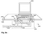
- FIG. 6 ais a schematic diagram of an inductive power outlet with an electrical load inductively coupled thereto, monitored by an efficiency monitor;
- FIG. 6 bis a schematic diagram of the inductive power outlet of FIG. 6 a wherein a power drain has been introduced between the primary and secondary coils;
- FIG. 7is a flow diagram of a method for using the signal transfer system to monitor the efficiency of power transmission by an inductive power outlet;
- FIG. 8 ais a schematic representation of another embodiment of the signal transfer system incorporated into a power outlet locator used to indicate the location of an inductive power outlet concealed behind a surface;
- FIG. 8 bis a schematic representation of a computer standing on the surface of FIG. 8 a and being powered by the concealed primary outlet;
- FIG. 9is a block diagram representing the main features of the power outlet locator.
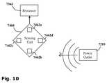
- FIG. 10is a schematic representation of a power outlet locator with four sensors
- FIG. 11is a block diagram representing a power outlet locator configured to receive and decode a control signal transmitted by a power outlet using still another embodiment of the signal transfer system;
- FIG. 12 a - care schematic representations of a mobile phone incorporating a power outlet locator, wherein a graphical user interface represents a virtual target superimposed over an image of the surface, and
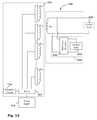
- FIG. 13is a schematic representation of a signal transfer system incorporated into a system for locating secondary coils placed upon a multi-coil power transmission surface.
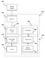
- FIG. 1showing a block diagram of the main elements of an inductive power coupling 200 incorporating a signal transfer system 100 according to a first embodiment of the invention.
- the inductive power coupling 200consists of a primary inductive coil 220 and a secondary inductive coil 260 .
- the primary coil 220is wired to a power supply 240 typically via a driver 230 which provides the electronics necessary to drive the primary coil 220 .
- Driving electronicsmay include a switching unit providing a high frequency oscillating voltage supply, for example.
- the secondary coil 260is wired to an electric load 280 .
- a power outlet 210may provide power to an electric device 290 .
- the signal transfer system 100comprises: a signal generator 120 , for generating a control signal S C ; a transmitter 140 for transmitting said control signal S C ; and a receiver 160 for receiving said control signal S C .
- the transmitter 140is incorporated into the power outlet 210 and the receiver 160 is incorporated into the electrical device 290 , it will be appreciated that a transmitter 140 may alternatively or additionally be incorporated into the electrical device 290 and a receiver 160 may alternatively or additionally be incorporated into the power outlet 210 .
- the control signal S Ccommunicates encoded data pertaining to the power transmission.
- This datamay be pertinent to regulating efficient power transmission. Examples of such data includes parameters such as: required operating voltage, current, temperature or power for the electric load 280 , the measured voltage, current, temperature or power supplied to the electric load 280 during operation, the measured voltage, current, temperature or power received by the electric load 280 during operation and the like.
- control signal S Cmay communicate data relating to the coordinates of the primary inductive coil 220 for the purposes of indicating the location of the power outlet 210 .
- control signal S Cmay communicate data relating to the identity or presence of the electric load 280 such as the location of the secondary coil 260 , or an identification code or the electric device 290 or its user.
- Various transmitters 140 and receivers 160may be used with the signal transfer system.
- optocouplersmay have a light emitting diode serving as a transmitter 140 which sends encoded optical signals over short distances to a photo-transistor which serves as a receiver 160 .
- Optocouplerstypically need to be aligned such that there is a line-of-sight between transmitter and receiver. In systems where alignment between the transmitter 140 and receiver 160 may be problematic, optocoupling may be inappropriate and alternative systems may be preferred such as ultrasonic signals transmitted by piezoelectric elements or radio signals such as Bluetooth, WiFi and the like.
- the primary and secondary coils 220 , 260may themselves serve as the transmitter 140 and receiver 160 .
- the inductive energy couplingcomprises a primary coil connectable to the power source in inductive alignment with a secondary coil connectable to the electric load, the system comprises at least one ancillary load; at least one switching unit comprising a modulator for modulating a bit-rate signal with an input signal to create a modulated signal and a switch for intermittently connecting the ancillary load to the secondary coil according to the modulated signal; at least one current monitor for monitoring primary current drawn by the primary coil and producing a primary current signal, and at least one correlator for cross-correlating the primary current signal with the bit-rate signal for producing an output signal.
- the switching unitpreferably also comprises a controller configured to encode data into the input signal.
- the switching unitfurther comprises a frequency divider and the inductive energy coupling transfers energy with a driving frequency and the bit rate frequency is an integer fraction of the driving frequency.
- the inductive energy couplingis typically a device wherein the primary coil is galvanically isolated from said secondary coil.
- the devicemay include a transformer, a DC-to-DC converter, an AC-to-DC converter, an AC-to-AC converter, a flyback transformer, a flyback converter, a full-bridge converter, a half-bridge converter, a buck converter, a boost converter, a buck-boost converter, a SEPIC converter or a zeta converter, for example.
- the input signalcarries encoded data pertaining to, for example, the presence of the electric load, required operating voltage for the electric load, required operating current for the electric load, required operating temperature for the electric load, measured operating voltage for the electric load, measured operating current for the electric load, measured operating temperature for the electric load, and/or a user identification code.
- a contactless inductive couplingcomprising the signal transfer system wherein the primary coil is embedded in a power jack and the secondary coil is embedded in a power plug galvanically isolated from the power jack.
- An aspect of the technology described hereinteaches a method for transferring a signal through an inductive energy coupling, wherein the inductive energy coupling comprises a primary coil connected to a power source and a secondary coil connected to an electric load, the method comprising the following steps: providing an input signal, providing a bit-rate signal, modulating the bit-rate signal with the input signal to create a modulated signal, connecting an ancillary load to the secondary coil intermittently according to the modulated signal, monitoring a primary current drawn by the primary coil and producing a primary current signal; and cross-correlating the primary current signal with the bit-rate signal to generate an output signal.
- a method for regulating power transfer across a contactless inductive couplingwherein the output signal provides details of power requirements of the load.
- the input signalis provided by encoding data regarding at least one power requirement of the electric load into the input signal.
- the power requirementdepends on parameters such as operating voltage, operating current and/or operating temperature.
- the input signalis provided by monitoring at least one operating parameter of the electric load and encoding monitored parameter data into the input signal.
- the parameteris selected from the group comprising operating voltage, operating current and operating temperature.
- the method for transferring a signal through an inductive energy couplingincludes a preliminary step of detecting the presence of an electric load.
- FIGS. 2 a - dwherein a signal transfer system 2100 according to a second general embodiment of the invention is shown.
- the signal transfer system 2100is configured to transmit a transmission signal through an inductive energy coupling 2200 .
- the inductive energy coupling 2200consists of a primary coil L 1 which may be connected to a power source 2240 and a secondary coil L 2 , galvanically isolated therefrom, across which an electric load 2280 may be connected either directly or via an AC-DC converter 2270 .
- a transmission circuit 2140may be connected in parallel with the electric load 2280 .
- the transmission circuit 2140comprises an ancillary load 2142 connected to the secondary coil L 2 via a switching unit 2144 .
- the ancillary load 2142is much smaller than the electric load 2280 .
- a corresponding reception circuit 2160is connected to the primary coil L 1 of the inductive energy coupling 2200 and comprises a current monitor 2162 , such as an ammeter in series with the primary coil L 1 , and a correlator 2164 .
- the switching unit 2144is configured to receive an input signal S in and a bit-rate signal F b .
- a modulator(not shown) modulates the bit-rate signal F b with the input signal S in to produce a modulated signal S M .
- the ancillary load 2142is intermittently connected to the secondary coil L 2 at a rate determined by the modulated signal S M .
- the power source 2240such as an alternating-current voltage source, intermittent direct current voltage source or the like, is configured and operable to produce a primary voltage V 1 which oscillates at a driving frequency F d .
- the oscillating primary voltage V 1 in coil L 1induces a secondary voltage V 2 (t) in the secondary coil L 2 .
- the secondary voltage V 2 (t)is optionally passed through an AC-DC converter 22 producing a direct-current voltage V 22 (t).
- the electric load 2280which is coupled to the secondary coil L 2 —either directly or via the AC-DC converter 2270 —draws a load current I 22 .
- the power P 22 provided to the load 2280is given by the scalar product of the voltage V 22 and the load current I 22 .
- an additional ancillary current i 24is also drawn.
- P 2 ( t )⁇ right arrow over (V) ⁇ 22 ( t ) ⁇ [ ⁇ right arrow over (I) ⁇ 22 + ⁇ right arrow over (i) ⁇ 24 ( t )]
- Input power P 1 (t) provided by the primary coil L 1is generally proportional to the total power P 22 (t) drawn by the secondary coil L 2 , and the primary voltage V 1 (t) is determined by the power supply. Perturbations in the primary current I 10 (t) supplied to the primary coil L 1 are thus in proportion with i 24 (t).
- the current monitor 2162monitors the primary current I 10 (t) over time, producing a primary current signal S p which typically has similar characteristics to the modulated signal S M .
- the correlator 2164is configured to cross-correlate the primary current signal S p with the bit rate F b .
- the output signal S out of the correlator 2164therefore has the same characteristics as the input signal S in .
- the signal transfer system 2100 described hereintransmits a transmission signal across the same inductive power coupling 2200 as used for power transmission. This is in contradistinction to prior art transmission systems, which use additional elements to provide signal transmission channels separate from the power transmission channels. In consequence of this innovative approach, additional transmission elements such as optocouplers, piezoelectric elements, supplementary coil pairs and the like are not generally required.
- An AC-to-DC converter 2270comprising a diode 2272 and a capacitor 2274 , which is connected in parallel to the secondary coil L 2 , converts an AC secondary voltage V 2 from the secondary coil L 2 into a DC load voltage V 22 which is connected across an electric load 2280 .
- the connection between the ancillary load 2142 and the load voltage V 2is controlled by a switching unit 2144 which includes a frequency divider 2145 , microcontroller 2146 and a switch 2147 .
- the frequency divider 2145provides the bit-rate signal F b which is passed to the microcontroller 2146 .
- the microcontroller 2146is configured to modulate the bit-rate signal F b according to input signals including control signals S C from the electric load 2280 and external signals S E . as described hereinbelow.
- Control signals S Cmay be used to regulate the power supply.
- Control signals S Ctypically provide data relating to load parameters. Typically these include the required operating voltage, current and temperature and the actual measured operating voltage, current and temperature as monitored during operation of the load.
- External Signals S Emay be used to provide the transmission circuit 2140 with external data to be digitally encoded into the input signal S in by the microcontroller 2146 and transmitted to the receiver circuit 2160 .
- External informationmay, for example, provide useful supplementary data such as a user identification code, a pass key, battery level of the load device and the like.
- FIG. 2 cshows a schematic representation of an exemplary receiver circuit 2160 in accordance with the signal transfer system of FIG. 2 a , consisting of a current monitor 2162 , a frequency divider 2166 , a correlator 2164 and a microcontroller 2168 .
- the frequency divider 2166provides the bit-rate signal F b which is typically an integer fraction of the driving frequency F d .
- the current monitor 2162provides a primary current signal S P which is passed to the correlator 2164 for cross-correlatation with the bit-rate signal F b .
- the resulting output signal S outis passed to a microcontroller 2168 which may use the output signal S out to pass a control signal S C to control the power source 2240 so as to regulate the power provided to the electric load 2280 .
- the microcontroller 2168may also be used to extract external signals S E from the output signal.
- FIG. 2 dshows the receiver circuit 2160 configured to control a flyback power source 2240 F.
- a direct current voltage source 2242is intermittently connected to a primary coil L 1 by a switch 2244 . This produces a varying voltage signal V 1 (t) in the primary coil L 1 which induces a secondary voltage V 2 in a secondary coil L 2 ( FIG. 2 a ).
- the secondary coil L 2is generally connected to a smoothing circuit such the AC-DC converter 2270 shown in FIG. 2 b to produce a DC output.
- the switch 2244is controlled by a driver 2248 which receives a pulsing signal F d from a clock 2246 .
- the pulsing signal F ddetermines the frequency with which the direct current voltage source 2242 is connected to the primary coil L 1 .
- the power delivered to the primary coil L 1may be regulated by varying the duty cycle of the switch 2244 .
- the duty cycleis the proportion of the time between pulses during which the switch 2244 is closed.
- FIG. 2 dshows the innovative use of the signal transfer system 2100 which receives a feedback signal transferred between the primary and secondary power transmission coils and received by the receiver circuit 2160 . This is an improvement on prior art flyback converters, wherein additional elements such as optocouplers or the like have been used to transmit feedback signals.
- the microcontroller 2168generates a control signal S C which is relayed to the driver 2248 .
- the control signal S Cdetermines the duty cycle of the switch 2248 and so may be used to regulate power transmission.
- a control signal S C thus transmittedmay be used to regulate power transfer in a variety of transmission assemblies such as a transformer, a DC-to-DC converter, an AC-to-DC converter, an AC-to-AC converter, a flyback transformer, a full-bridge converter, a half-bridge converter or a forward converter for example.
- a signal transfer system 3100may be integrated into a contactless inductive power coupling system 3200 where power is inductively transmitted from a jack unit 3212 to a plug unit 3292 galvanically isolated therefrom.
- a transmission circuit 3140 embedded in the plug unit 3292may be used to transmit control signals S C to a receiver circuit 3160 in the jack 3212 .
- control signalsmay be passed between the plug 3292 and jack 3212 units with no need to align additional components such as optocouplers, and the like.
- the signal transfer system 3100may be used to detect the presence of the load 3290 producing a detection signal S DL and then to provide the jack 3212 with signals relating to the identity of the user S ID and the serial number S SN or other identifier of the laptop computer 3290 .
- Signals regarding the operating voltage and current required by the PCmay be provided as a regulatory signal S Q which may also provide supplementary information such as information related to the power level of the cells 3280 , for example.
- the signal transfer system 3100may be used to select between powering the computer 3290 directly, recharging the power cells 3280 thereof, or both powering and recharging, depending on defaults and predetermined criteria. It is further noted that when used for recharging cells 3280 , the ability to monitor the temperature of the cells 3280 during recharging may be used to prevent overheating.
- FIG. 4a flowchart showing a method for transferring a transmission signal through an inductive energy coupling in accordance with another embodiment of the invention is presented.
- an Input Signal S in —Step (a) and a Bit-rate Signal F b —Step (b)are provided to the transmission circuit 2140 .
- the Bit-rate Signal F bis then modulated by the Input Signal S in , producing a Modulated Signal S M —Step (c).
- An ancillary load 2142is then connected to the second coil L 2 intermittently according to the Modulated Signal S M —Step (e).
- the receiver circuit 2160monitors the primary current drawn by the primary coil L 1 to produce a Primary Current Signal S P —Step (e). This Primary Current Signal S P is then cross-correlated with the Bit-rate Signal F b to generate an Output Signal S out —Step (f).
- the basic signal transfer system and method described hereinaboveare capable of variation. For example, it will be appreciated that through the use of such a system, information regarding a load 2280 may be transmitted to the power outlet 2210 across the inductor coils L 1 and L 2 of the inductive coupling 2200 , as a signal superimposed on the power transmitted, without requiring additional data transmitting components.
- Embodiments of the inventionare directed to providing methods for monitoring the efficiency of power transmission by an inductive power outlet comprising at least one primary coil wired to a power supply, for inductively coupling with a secondary coil wired to an electric device.
- the methodcomprises the steps of: measuring the input power delivered to the primary coil, measuring the output power received by the electric device, communicating the input power to a processor, communicating the output power to the processor and the processor determining an index of power-loss.
- the index of power-lossis an efficiency quotient Q, being the ratio of the output power to the input power
- the methodcomprises the further step of: disconnecting the primary coil from the power supply if the efficiency quotient Q is below a threshold value.
- the threshold efficiency quotientis in the range of from 75% to 95%.
- the index of power-lossis an efficiency differential ⁇ , being the difference between the output power to the input power
- the methodcomprises the further step of: disconnecting the primary coil from the power supply if the efficiency differential ⁇ is above a threshold value.
- a further aspect of the technology described hereinrelates to an efficiency monitor for monitoring the efficiency of power transmission by an inductive power outlet of the type including at least one primary coil wired to a power supply, for inductively coupling with a secondary coil wired to an electric device.
- the efficiency monitorincludes: at least one input power monitor for measuring the input power delivered to the primary coil; at least one output power monitor for measuring the output power received by the secondary coil; at least one processor for determining an index of power-loss; and at least one communication channel for communicating the input power and the output power to the processor.
- the efficiency monitoralso includes at least one circuit-breaker for disconnecting the primary coil from the power supply.
- the input power monitoris incorporated within the power outlet and the output power monitor is incorporated within the electric device.
- the electric devicecomprises at least one transmitter for transmitting the output power to a receiver incorporated in the power outlet.
- the transmittermay include one or more light emitting diodes, radio transmitters, optocouplers, or ancillary load transmitter circuits, for example.
- the efficiency monitorincludes one or more hazard detectors in communication with the processor.
- hazard detectorsmay include magnetic sensors, heat sensors, electromagnetic radiation sensors and Hall probes, for example.
- FIG. 5showing a block diagram of a signal transfer system 4100 .
- the signal transfer system 4100is incorporated into an efficiency monitor 4300 for monitoring the efficiency of power transmission by an inductive power outlet 4210 .
- the inductive power outlet 4210consists of a primary coil 4220 wired to a power supply 4240 via a driver 4230 which provides the electronics necessary to drive the primary coil 4220 .
- Driving electronicsmay include a switching unit providing a high frequency oscillating voltage supply, for example.
- the pair of coilsforms an inductive couple, and power is transferred from the primary coil 4220 to the secondary coil 4260 .
- the power outlet 4210may provide power to an electric device 4262 comprising an electric load 4280 wired in series with the secondary coil 4260 .
- the efficiency monitor 4300consists of an input power monitor 4122 incorporated within the power outlet 4210 and an output power monitor 4124 incorporated within the electric device 4290 , both in communication with a processor 4162 .
- the input power monitor 4122is configured to measure the input power P in provided by the primary coil 4220 and communicates this value to the processor 4162 .
- the output power monitor 4124is configured to measure the output power P out received by the secondary coil 4260 and communicates this value to the processor 4162 .
- the processor 4162is configured to receive the values of the input power P in and the output power P out and to calculate an index of power-loss.
- the index of power lossindicates how much power is leaking from the inductive couple.
- the index of power-lossmay be the efficiency quotient Q which is the ratio between them, P out /P in , which is an indication of the efficiency of the inductive coupling.
- the index of power lossmay be the efficiency differential ⁇ which is the difference between P out and P in .
- the processor 4162may additionally or alternatively be configured to trigger a circuit-breaker 4280 thereby cutting off the primary coil 4220 from the power supply 4240 when the efficiency quotient Q falls below a predetermined threshold or the efficiency differential ⁇ rises above a predetermined threshold.
- this predetermined threshold for the efficiency quotient Qis in the range of from about 75% to 95%, and more preferably about 85%.
- Inductive power outlet 5210consists of a primary coil 5220 wired to a power source 5240 via an efficiency monitor 5300 all concealed behind a facing layer 5642 of a horizontal platform 5640 such as a desk-top, a kitchen work-top, a conference table or a work bench.
- the facing layermay be a sheet of self-adhesive plastic film, plastic, vinyl, Formica or wood veneer, for example.
- a primary coil 5220may be concealed beneath or within flooring such as rugs, fitted carpet, parquet, linoleum, floor tiles, tiling, paving and the like.
- the primary coil 5220may be concealed behind or within a vertical surface such as a wall of a building or a cabinet, for example behind wallpaper or stretched canvas or the like.
- the primary coil 5220may be used to power an electrical device 5290 such as a computer wired to a secondary coil 5260 .
- the electrical device 5290is placed upon the surface 5642 of a platform 5640 such that the secondary coil 5260 is aligned with the primary coil 5220 therebeneath.
- the efficiency of the power outlet 5210is monitored by an efficiency monitor 5300 .
- An input power monitor 5122is incorporated within the power outlet 5210 behind the platform 5640 and is in direct conductive communication with a processor 5162 .
- An output power monitor 5124is incorporated within the electrical device 5290 and is not physically connected to the power outlet 5210 .
- the output power monitor 5124communicates with the processor 5162 via a signal transfer system 5100 comprising a transmitter 5140 incorporated within the electrical device 5290 which is configured to transmit a signal to a receiver 5160 incorporated within the power outlet 5210 .
- the transmitter 5140may be a standard transmitter such as those widely used in computing and telecommunications, such as an Infra-red, Wi-fi or Bluetooth transmitter or the like. Indeed, any light emitting diodes, radio transmitters, optocouplers or other such transmitters of radiation for which the platform 5640 is translucent may be used. Alternatively a fiber optic pathway may be provided through the platform.
- an optical transmittersuch as a light emitting diode (LED) for example, is incorporated within the power outlet 5210 and is configured and operable to transmit electromagnetic radiation of a type and intensity capable of penetrating the casing of the electrical device 5290 , and the surface layer 5642 .
- An optical receiversuch as a photodiode, a phototransistor, a light dependent resistors of the like, is incorporated within the primary unit for receiving the electromagnetic radiation transmitted through the surface layer 5642 .
- an infra-red signalmay be used to provide a communication channel between primary and secondary units galvanically isolated from each other by a few hundred microns of wood, plastic, Formica, wood veneer, glass or the like.
- the transmitter 5140 and receiver 5160may be laterally displaced from the primary coil 5220 and secondary coil 5260 . In preferred embodiments, however, the transmitter 5140 is located at the center of the secondary coil 5260 and the receiver 5160 is located at the center of the primary coil 5220 . This permits alignment to be maintained through 360 degree rotation of the secondary coil 5260 relative to the primary coil 5220 .
- the processor 5162is configured to receive the values of the input power P in , directly from the input power monitor 5122 , and the output power P out , via the receiver 5160 . The processor 5162 then calculates the efficiency quotient Q. In normal usage as represented in FIG. 6 a , the processor records an efficiency quotient Q higher than a predetermined threshold so power transmission continues uninterrupted. When the efficiency quotient Q falls below a predetermined threshold, this indicates that power is being drawn from the primary coil 5220 by some power drain other than the secondary coil 5260 .
- FIG. 6 bis a schematic diagram of the inductive power outlet 5210 of FIG. 6 a wherein a power drain such as a conductive sheet of metallic foil 5800 is introduced between the primary coil 5220 and the secondary coil 5260 .
- a power drainsuch as a conductive sheet of metallic foil 5800 is introduced between the primary coil 5220 and the secondary coil 5260 .
- the oscillating magnetic field produced by the primary coil 5220when connected to a high frequency oscillating voltage from a driver 5230 , produces eddy currents in the conductive sheet 5800 thereby heating the conductive sheet and draining power from the primary coil 5220 .
- Such a power drainmay be wasteful and/or dangerous. It will be appreciated that leak prevention systems which cut off power to the primary coil 5220 if no secondary coil 5260 is coupled thereto, would fail to detect this hazard.
- embodiments of the present inventionmeasure the efficiency quotient Q. Consequently, when a power drain is introduced, such as that shown in FIG. 6 b , for example, the output power P out received by the secondary coil 5260 is lower than normal and the efficiency quotient Q may therefore drop below the predetermined threshold. The efficiency monitor 5300 is thus able to detect the hazard.
- additional detectorsmay be incorporated within the power outlet 5210 , the platform 5640 or the electrical device 5290 for monitoring other scientific effects which may be indications of possible hazards such as the magnetic field generated by the primary coil 5220 , or the temperature of the platform 5640 for example.
- Such detectorsmay function in accordance with one or more of a variety of principles, including, inter alia, magnetic sensing means, Hall probes, heat sensors or electromagnetic sensors.
- the processor 5162may assess the level of the hazard detected by processing the various signals received according to a predetermined logical sequence. If necessary, the processor 5162 may trigger a circuit-breaker 5280 thereby cutting off the primary coil 5220 from the power supply 5240 . Depending on the nature of the hazard, the processor 5162 may additionally or alternatively alert a user to the hazard.
- the alertmay be a visual or audio alarm for example, such as a buzzer or light incorporated in the power transmission surface, or a signal sent to the computer 5290 which displays a warning 5294 on its visual display 5296 or emits a warning sound.
- the output power P outmay be monitored and encoded into the input signal Sin.
- the coil-to-coil signal generator shown in FIG. 2 amay be used to transmit the input signal Sin from a transmission circuit 2140 ( FIG. 2 a ) incorporated within an electrical device 290 ( FIG. 1 ) and is retrievable by the receiver circuit 2160 ( FIG. 2 a ) incorporated within the power outlet 210 ( FIG. 1 ) from the output signal Sout.
- the retrieved signalmay then be communicated to a processor which uses it to calculate the efficiency quotient Q.
- FIG. 7showing a flow diagram of a method for monitoring the efficiency of power transmission by an inductive power outlet according to a further embodiment of the present invention.
- the methodincludes the following steps:
- the power outlet locatorfor locating an inductive power outlet of the type comprising at least one primary coil wired to a power supply for inductively coupling with a secondary coil wired to an electrical device.
- the power outlet locatorcomprises at least one sensor for detecting the at least one power outlet, at least one processor for receiving a sensor signal from the at least one sensor and computing at least one coordinate of a location of the at least one power outlet and at least one user interface for receiving a signal from the processor and communicating the location to a user.
- At least one sensoris selected to detect radiation transmitted by the at least one the power outlet.
- at least one sensoris selected to detect an electromagnetic field generated by at least one the primary coil.
- the processorcalculates the distance between the sensor and the power outlet by comparing the intensity of the radiation received by the sensor with a reference value.
- the processordetermines the direction to the power outlet by comparing the relative intensities of the radiation detected by a plurality of the sensors.
- the location of the power outletis encoded into a signal transmitted by the power outlet and decoded by the processor.
- the user interfacecomprises a visual display.
- the visual displayindicates the direction of the power outlet.
- the visual displayindicates the distance to the power outlet.
- the visual displaycomprises a graphical user interface representing at least a section of a target comprising concentric rings centered on a point indicating the location of the power outlet.
- the power outletis concealed behind a surface and the target is superimposed upon an image of the surface.
- the user interfacecomprises an audible signal.
- the electrical deviceadditionally comprises at least one secondary inductive coil for powering the electrical device.
- the electrical deviceadditionally comprises at least one electrochemical power cell for powering the electrical device and at least one the secondary inductive coil wired to the electrochemical cell via a rectifier for charging the electrochemical power cell.
- the electrical devicemay be, but is not necessarily, selected from the group comprising: telephones, personal digital assistants (PDAs), cameras, media players, computers, keyboards and mice.
- FIG. 8 ashowing a schematic representation of such a power outlet locator 6300 which utilizes such a signal transfer system.
- the inductive power outlet 6210is wired to a power source typically via a driver 230 ( FIG. 1 ) providing the electronics necessary to drive the inductive power outlet 6210 , such as a switching unit providing a high frequency oscillating voltage supply, for example.
- a driver 230FIG. 1
- the inductive power outlet 6210may be incorporated into a vertical surface such as a wall of a building or a cabinet.
- the inductive power outlet 6210may be concealed behind a surface 6642 of wallpaper or stretched canvas for example.
- the inductive power outlet 6210may be incorporated behind a facing layer of a horizontal platform such as a desk-top, a kitchen work-top, a conference table or a work bench for example of mica, Formica or wood veneer.
- an inductive power outlet 6210may be concealed beneath flooring such as rugs, fitted carpet, parquet, linoleum, floor tiles, tiling, paving and the like.
- a secondary coil 6260may be brought into alignment therewith, as shown in FIG. 8 b , for example.
- the inductive power outlet 6210may inductively couple with the secondary coil 6260 and thereby power an electrical device, such as a computer 6290 , wired to the secondary coil 6260 .
- the electrical devicesuch as a computer 6290 may itself incorporate an integral inductive power outlet locator.
- a sensing unit 7160configured and operable to detect an inductive power outlet 7210 is provided.
- a processor 7362in communication with the sensing unit 7160 , is configured to compute the location of the power outlet 7210 .
- a user interface 7360is provided for communicating the computed location to a user.
- the sensor unit 7160may incorporate magnetic sensors such as Hall probes, for example, configured to detect the magnetic field generated by the inductive power outlet directly.
- the sensor unit 7160may incorporate a radio receiver for receiving a radio signal transmitted from the power outlet. It will be appreciated, however, that appropriate sensors may be selected for detecting specific electromagnetic wavelengths, including ultra-violet radiation, micro waves, radio waves or even x-ray or shorter wavelengths.
- the sensing unitmay be configured to receive other types of radiation, including mechanical vibrations such as both audible and inaudible (e.g. ultrasonic) sound waves.
- an exemplary sensing unit 7460is represented in FIG. 10 , four sensors 7462 a - d , such as proximity sensors based on volume sensors, infra-red sensors, ultrasonic sensors, magnetic sensors (like Hall probes), inductance sensors, capacitance sensors or the like, are arranged in a diamond configuration.
- sensors 7462 a - dsuch as proximity sensors based on volume sensors, infra-red sensors, ultrasonic sensors, magnetic sensors (like Hall probes), inductance sensors, capacitance sensors or the like, are arranged in a diamond configuration.
- Each sensor 7462is configured to receive a control signal S C transmitted from an inductive power outlet 7210 .
- the processor 7362may compare the intensity I of the control signal SC detected by a sensor 7462 with a reference value I r to indicate the distance between the sensor 7462 and the power outlet 7210 .
- the diamond configurationprovides two perpendicular opposing pairs of sensors 7462 a - b , 7462 c - d .
- the intensity I of the control signal SCis measured by each sensor independently.
- the processor 7460may use the differences between intensities measured by opposing pairs (I a -I b ), (I c -I d ) to provide vector coordinates indicating the direction of the power outlet 7210 .
- a two dimensional vectoris computed using the two dimensional diamond configuration of sensors described hereinabove, it will be appreciated that a three dimensional vector may be computed from three pairs of sensors in a tetrahedral configuration.
- FIG. 11shows a block diagram representing a power outlet locator 8500 in accordance with yet another embodiment.
- An inductive power outlet 8210transmits a control signal S C which carries an encoded location signal S L identifying the location of the inductive power outlet 8210 .
- a primary coil 8220is connected to a power supply 8240 via a switching unit 8232 and a microcontroller 8234 .
- the switching unit 8232is configured to intermittently connect the power supply 8240 to the primary coil 8220 with a bit-rate frequency f .
- the location of the primary coil 8220is encoded into a location signal S L which is sent to the microcontroller 8234 .
- the microcontroller 8234is configured to modulate the bit-rate signal with the location signal S L .
- the voltage applied to the primary coil 8220is thus a modulated variable voltage with a frequency f , carrying an encoded location signal S L .
- the variable voltagemay produce a radio wave of frequency f which may be transmitted as a control signal S C .
- the control signal S Cmay be transmitted by a dedicated transmitter separate from the primary coil 8220 .
- the power outlet locator 8500includes a receiver 8160 , a clock 8542 and a cross-correlator 8544 .
- the radio receiver 8160is tunable to receive radio waves of frequency f, such that it may receive the control signal S C .
- the clock 8542produces a fixed reference signal R of frequency f.
- the cross-correlator 8544receives both the reference signal R from the clock 8542 and the control signal S C from the receiver 8160 and by cross-correlating these signals the location signal S L is isolated.
- control signal S Cmay alternatively be modulated in other ways such as by analogue or digital frequency modulation or by amplitude modulation, for example.
- the location of the power outlet 8210may thereby be transmitted to a remote power outlet indicator 8500 , which may then output the location of the power outlet 8210 a user interface 7360 ( FIG. 9 ).
- a power outlet locator 9300may be incorporated into a mobile phone 9290 , for example, thereby providing a convenient means of locating concealed inductive power outlets.
- a graphical user interface 9360displayed upon the visual display of the mobile phone 9290 , represents a virtual target 9660 , centered upon the power outlet (not shown) and superimposed over the surface 9640 behind which the power outlet is concealed.
- the whole of the virtual target 9660is represented by a dotted line in FIGS. 12 a - c for convenience, only the section 9661 a - c of the virtual target 9660 in the visual display 9360 of the mobile phone 9290 will normally be visible.
- the displayed sectiondepends upon the location of the mobile phone 9290 .
- the curvature of the visible concentric arcsmay indicate both the direction and distance to the power outlet.
- the virtual target 9660may be displayed upon a blank background or alternatively may be superimposed upon an image of the surface 9640 , for example a real time image produced by the camera (not shown) of the mobile phone 9660 .
- the mobile phone 9290may itself carry a secondary inductive coil (not shown) wired to a electrochemical cell via a rectifier for inductively coupling with a inductive power outlet and charging the electrochemical power cell.
- Optimal alignment between the secondary coil and the inductive power outletmay additionally be indicated by an audible signal such as a ring-tone or the like.
- an audible signalmay be additionally or alternatively be provided to guide the user to the power outlet, perhaps verbally or alternatively through other variations in pitch, volume or timbre.
- a power outlet locator 9300which draws power from the mobile phone 9290 is impractical.
- a power outlet locatormay be an independently powered unit with a user interface separate from that of the mobile phone 9290 .
- the power outlet locatordraws power from the secondary inductive coil.
- itmay include a dedicated electrochemical power source, for example. The relative brightness of four light emitting diodes mounted upon the corners of the mobile phone may indicate both the direction and proximity to a primary coil.
- the power outlet locator 9300is incorporated into a mobile phone 9290 it is noted that such a power outlet locator may alternatively be incorporated within other electrical devices such as fixed telephones, personal digital assistants (PDAs), cameras, media players, computers, keyboards, cursor controllers (e.g. mice) and the like.
- the signal transfer systemmay be associated with the primary coil and used to detect the location of the secondary inductive coil. For example, in a power outlet surface comprising multiple primary coils, each primary coil may be independently connected to the power source via a driver. The signal transfer system may be used to identify the primary coil closest to the location of a secondary coil. Typically, the primary coils may be driven at multiple power levels, such that a low power level is used to locate the secondary coil and a higher power is used to transfer power when a secondary coil is located.
- the secondary coilis wired to a transmission circuit comprising an ancillary load connectable to the secondary coil via a half-wave rectifier, such as a diode.
- the transmission circuitmay also comprise a smoothing capacitor, a low power current source and a DC to DC converter.
- the driverWhen in detection mode, the driver activates each primary coil sequentially at low power.
- the low power pulseWhen a secondary coil is close enough to a primary coil to inductively couple with it, the low power pulse is transferred from the primary coil to the secondary coil.
- An AC voltageis induced in the secondary coil and the transmission circuit is activated.
- a DC currentis produced by the half-wave rectifier and flows through the ancillary load.
- a control signalis transmitted by the secondary coil due to the transmission circuit. Because half-wave rectification is used, even harmonics of the power transmission frequency are generated. These may be detected by a reception circuit connected to the primary coil, for example by cross-correlating the power transmission frequency with a reference clock frequency.
- the strength of the even harmonic signalsmay indicate the proximity of the primary to the secondary coil. Once a secondary coil is detected, the driver may switch the closest primary coil to power transmission mode, typically at a higher power.
- FIG. 13shows the signal transfer system 2101 according to yet another embodiment of the invention.
- the signal transfer system 2101is used for locating a secondary coil L 22 wired to an electric load 2281 , which is placed somewhere over a multi-coil power transmission surface 2211 .
- the multi-coil power transmission surface 2211comprises an array of primary coils L 1n each connected to a driver 2231 wired to a power source 2241 .
- the signal transfer system 2101includes a transmission circuit 2141 wired to the secondary coil 2221 and a reception circuit 2161 connected to the driver 2231 .
- the transmission circuit 2141includes a half-wave rectifier 2144 connected to an ancillary load 2142 and the reception circuit 2161 is configured to detect second harmonic signals in the power supplied to the primary inductive coil L 1n when the secondary inductive coil L 22 is coupled thereto.
- the driver 2231is configured to selectively operate each primary inductive coil L 1n in turn preferably at low power so as to identify which primary inductive coil is closest to the secondary inductive coil L 22 . When a secondary coil L 22 is detected, the driver 2231 is then configured to operate the primary inductive coil L 1n closest to the secondary inductive coil L 22 at a high power. It will be appreciated that for some purposes it may be desirable to disconnect the transmission circuit 2141 after the secondary inductive coil L 22 is coupled to a primary coil L 1n .
Landscapes
- Engineering & Computer Science (AREA)
- Power Engineering (AREA)
- Computer Networks & Wireless Communication (AREA)
- Physics & Mathematics (AREA)
- Electromagnetism (AREA)
- Remote Sensing (AREA)
- Life Sciences & Earth Sciences (AREA)
- General Physics & Mathematics (AREA)
- Geology (AREA)
- General Life Sciences & Earth Sciences (AREA)
- Environmental & Geological Engineering (AREA)
- Geophysics (AREA)
- Charge And Discharge Circuits For Batteries Or The Like (AREA)
- Supply And Distribution Of Alternating Current (AREA)
- Current-Collector Devices For Electrically Propelled Vehicles (AREA)
- Direct Current Feeding And Distribution (AREA)
- Control Of Motors That Do Not Use Commutators (AREA)
- Train Traffic Observation, Control, And Security (AREA)
- Remote Monitoring And Control Of Power-Distribution Networks (AREA)
- Measurement And Recording Of Electrical Phenomena And Electrical Characteristics Of The Living Body (AREA)
- Near-Field Transmission Systems (AREA)
- Control Of Conveyors (AREA)
- Cable Transmission Systems, Equalization Of Radio And Reduction Of Echo (AREA)
Abstract
Description
- a. at least one signal generator for generating a control signal;
- b. at least one transmitter for transmitting said control signal, and
- c. at least one receiver for receiving said control signal.
Optionally and preferably, the control signal for carrying encoded data pertains to at least one of the group comprising: - d. presence of said electric load;
- e. location of said primary inductive coil;
- f. location of said secondary inductive coil;
- g. required operating voltage for said electric load;
- h. required operating current for said electric load;
- i. required operating temperature for said electric load;
- j. required operating power for said electric load;
- k. measured operating voltage for said electric load;
- l. measured operating current for said electric load;
- m. measured operating temperature for said electric load;
- n. measured operating power for said electric load;
- o. power delivered to said primary inductive coil;
- p. power received by said secondary inductive coil, and
- q. a user identification code.
- said switching unit further comprises a controller configured to encode data into said input signal;
- said switching unit further comprises a frequency divider;
- said inductive power coupling transfers energy with a driving frequency and said bit rate frequency is an integer fraction of said driving frequency;
- said inductive power coupling is a device selected from the group comprising: a transformer, a DC-to-DC converter, an AC-to-DC converter, an AC-to-AC converter, a flyback transformer, a flyback converter, a full-bridge converter, a half-bridge converter and a forward converter; and
- said primary inductive coil is galvanically isolated from said secondary inductive coil.
- the efficiency monitor additionally comprises at least one circuit-breaker for disconnecting said primary inductive coil from said power supply;
- the input power monitor is incorporated into an inductive power outlet;
- the output power monitor is incorporated into an electric device;
- the index of power-loss is an efficiency quotient Q, defined as the ratio of said output power to said input power;
- the index of power-loss is an efficiency differential Δ, defined as the difference between said output power and said input power, and
- the efficiency monitor additionally comprises hazard detectors in communication with said processor.
- at least one sensor for detecting said control signal;
- at least one processor for receiving a sensor signal from said at least one sensor and computing at least one coordinate of a location of said power outlet, and
- at least one user interface for receiving a signal from said processor and communicating said location to a user.
- the at least one sensor being selected to detect an electromagnetic field generated by at least one said primary inductive coil;
- the processor calculates the distance between said sensor and said power outlet by comparing the intensity of said control signal received by the sensor with a reference value;
- the processor determines the direction of said power outlet by comparing the relative intensities of said control signal as detected by a plurality of said sensors;
- the location of said power outlet being encoded into said control signal and decoded by said processor;
- the user interface comprises a visual display for indicating the location of said power outlet, and
- the user interface comprises an audible signal.
- the electrical device additionally comprises at least one said secondary inductive coil for powering said electrical device;
- the electrical device additionally comprises at least one electrochemical power cell for powering said electrical device and at least one said secondary inductive coil wired to said electrochemical cell via a rectifier for charging said electrochemical power cell, and
- the electrical device is selected from the group comprising: telephones, personal digital assistants (PDAs), cameras, media players, computers, keyboards and cursor controllers.
- providing an input signal;
- providing a bit-rate signal;
- modulating the bit-rate signal with the input signal to create a modulated signal;
- connecting an ancillary load to said secondary inductive coil intermittently according to said modulated signal;
- monitoring a primary current drawn by said primary inductive coil and producing a primary current signal, and
- cross-correlating said primary current signal with said bit-rate signal to generate an output signal.
- measuring the input power delivered to said primary inductive coil;
- measuring the output power received by said electric device;
- communicating said input power to a processor;
- communicating said output power to said processor, and
- said processor determining an index of power-loss.
P2(t)={right arrow over (V)}22(t)·[{right arrow over (I)}22+{right arrow over (i)}24(t)]
P1(t)={right arrow over (V)}1(t)·{right arrow over (I)}10(t)
where the primary voltage V1(t) oscillates at the driving frequency Fdwhich is determined by the
- a) measuring the input power delivered to a primary coil;
- b) measuring the output power received by an electric device;
- c) communicating the input power Pinto a processor;
- d) communicating the output power Poutto the processor;
- e) determining an index of power-loss, such as an efficiency quotient Q or efficiency differential Δ;
- f) optionally, disconnecting the primary coil from the power supply, for example if the efficiency quotient Q is below a threshold value (f1) or the efficiency differential Δ is above a threshold value (f2), thereby preventing power leakage.
Primary Coil Locators
Claims (9)
Priority Applications (2)
| Application Number | Priority Date | Filing Date | Title |
|---|---|---|---|
| US12/563,544US8749097B2 (en) | 2007-03-22 | 2009-09-21 | System and method for controlling power transfer across an inductive power coupling |
| US13/228,991US20120038619A1 (en) | 2007-03-22 | 2011-09-09 | System and method for controlling inductive power to multiple modules |
Applications Claiming Priority (8)
| Application Number | Priority Date | Filing Date | Title |
|---|---|---|---|
| US90713207P | 2007-03-22 | 2007-03-22 | |
| US93584707P | 2007-09-04 | 2007-09-04 | |
| US607607P | 2007-12-18 | 2007-12-18 | |
| US610607P | 2007-12-19 | 2007-12-19 | |
| US648808P | 2008-01-16 | 2008-01-16 | |
| US672108P | 2008-01-29 | 2008-01-29 | |
| PCT/IL2008/000401WO2008114268A2 (en) | 2007-03-22 | 2008-03-23 | Signal transfer system |
| US12/563,544US8749097B2 (en) | 2007-03-22 | 2009-09-21 | System and method for controlling power transfer across an inductive power coupling |
Related Parent Applications (1)
| Application Number | Title | Priority Date | Filing Date |
|---|---|---|---|
| PCT/IL2008/000401ContinuationWO2008114268A2 (en) | 2007-03-22 | 2008-03-23 | Signal transfer system |
Related Child Applications (1)
| Application Number | Title | Priority Date | Filing Date |
|---|---|---|---|
| PCT/IL2010/000209Continuation-In-PartWO2010103525A2 (en) | 2007-03-22 | 2010-03-11 | System and method for controlling inductive power to multiple modules |
Publications (2)
| Publication Number | Publication Date |
|---|---|
| US20100072825A1 US20100072825A1 (en) | 2010-03-25 |
| US8749097B2true US8749097B2 (en) | 2014-06-10 |
Family
ID=39591688
Family Applications (7)
| Application Number | Title | Priority Date | Filing Date |
|---|---|---|---|
| US12/563,635Active2030-07-07US8441364B2 (en) | 2007-03-22 | 2009-09-21 | Inductive power outlet locator |
| US12/563,544Active2028-06-27US8749097B2 (en) | 2007-03-22 | 2009-09-21 | System and method for controlling power transfer across an inductive power coupling |
| US12/563,558Active2028-10-06US8090550B2 (en) | 2007-03-22 | 2009-09-21 | Efficiency monitor for inductive power transmission |
| US13/306,379ActiveUS8626461B2 (en) | 2007-03-22 | 2011-11-29 | Efficiency monitor for inductive power transmission |
| US14/098,880ActiveUS8965720B2 (en) | 2007-03-22 | 2013-12-06 | Efficiency monitor for inductive power transmission |
| US14/323,124Active2028-04-07US9362049B2 (en) | 2007-03-22 | 2014-07-03 | Efficiency monitor for inductive power transmission |
| US15/167,313Active2028-11-04US10742076B2 (en) | 2007-03-22 | 2016-05-27 | Inductive power outlet locator |
Family Applications Before (1)
| Application Number | Title | Priority Date | Filing Date |
|---|---|---|---|
| US12/563,635Active2030-07-07US8441364B2 (en) | 2007-03-22 | 2009-09-21 | Inductive power outlet locator |
Family Applications After (5)
| Application Number | Title | Priority Date | Filing Date |
|---|---|---|---|
| US12/563,558Active2028-10-06US8090550B2 (en) | 2007-03-22 | 2009-09-21 | Efficiency monitor for inductive power transmission |
| US13/306,379ActiveUS8626461B2 (en) | 2007-03-22 | 2011-11-29 | Efficiency monitor for inductive power transmission |
| US14/098,880ActiveUS8965720B2 (en) | 2007-03-22 | 2013-12-06 | Efficiency monitor for inductive power transmission |
| US14/323,124Active2028-04-07US9362049B2 (en) | 2007-03-22 | 2014-07-03 | Efficiency monitor for inductive power transmission |
| US15/167,313Active2028-11-04US10742076B2 (en) | 2007-03-22 | 2016-05-27 | Inductive power outlet locator |
Country Status (15)
| Country | Link |
|---|---|
| US (7) | US8441364B2 (en) |
| EP (5) | EP3975372B1 (en) |
| JP (2) | JP2010522534A (en) |
| KR (2) | KR101552738B1 (en) |
| CN (1) | CN102106054A (en) |
| AU (2) | AU2008227850A1 (en) |
| CA (1) | CA2681613C (en) |
| ES (1) | ES2894931T3 (en) |
| HR (1) | HRP20211554T1 (en) |
| IL (2) | IL201087A (en) |
| MX (2) | MX2009010134A (en) |
| PL (1) | PL2154763T3 (en) |
| PT (1) | PT2154763T (en) |
| SI (1) | SI2154763T1 (en) |
| WO (1) | WO2008114268A2 (en) |
Cited By (9)
| Publication number | Priority date | Publication date | Assignee | Title |
|---|---|---|---|---|
| US20160087480A1 (en)* | 2014-09-23 | 2016-03-24 | Qualcomm Incorporated | Charging Apparatus Including Remote Device Reset |
| US9564760B2 (en) | 2011-12-07 | 2017-02-07 | Semiconductor Energy Laboratory Co., Ltd. | Contactless power feeding system |
| US20170294808A1 (en)* | 2008-03-17 | 2017-10-12 | Powermat Technologies, Ltd. | Transmission-guard system and method for an inductive power supply |
| US9923417B2 (en) | 2011-06-17 | 2018-03-20 | Semiconductor Energy Laboratory Co., Ltd. | Wireless power feeding system |
| US20200044468A1 (en)* | 2018-07-31 | 2020-02-06 | Ling Yung LIN | Mobile power supply module with light source |
| US11114895B2 (en) | 2007-01-29 | 2021-09-07 | Powermat Technologies, Ltd. | Pinless power coupling |
| US11387688B2 (en) | 2008-07-02 | 2022-07-12 | Powermat Technologies, Ltd. | System and method for coded communication signals regulating inductive power transmissions |
| US20220271795A1 (en)* | 2019-11-11 | 2022-08-25 | Huawei Technologies Co., Ltd. | Method, apparatus, and system for information transmission in plc network |
| US11979201B2 (en) | 2008-07-02 | 2024-05-07 | Powermat Technologies Ltd. | System and method for coded communication signals regulating inductive power transmissions |
Families Citing this family (231)
| Publication number | Priority date | Publication date | Assignee | Title |
|---|---|---|---|---|
| US7065658B1 (en) | 2001-05-18 | 2006-06-20 | Palm, Incorporated | Method and apparatus for synchronizing and recharging a connector-less portable computer system |
| US11201500B2 (en) | 2006-01-31 | 2021-12-14 | Mojo Mobility, Inc. | Efficiencies and flexibilities in inductive (wireless) charging |
| US8169185B2 (en) | 2006-01-31 | 2012-05-01 | Mojo Mobility, Inc. | System and method for inductive charging of portable devices |
| US7952322B2 (en)* | 2006-01-31 | 2011-05-31 | Mojo Mobility, Inc. | Inductive power source and charging system |
| WO2007107642A1 (en)* | 2006-03-21 | 2007-09-27 | Tmms Co., Ltd. | Device for transporting energy by partial influence through a dielectric medium |
| US7948208B2 (en) | 2006-06-01 | 2011-05-24 | Mojo Mobility, Inc. | Power source, charging system, and inductive receiver for mobile devices |
| US11329511B2 (en) | 2006-06-01 | 2022-05-10 | Mojo Mobility Inc. | Power source, charging system, and inductive receiver for mobile devices |
| EP3975372B1 (en) | 2007-03-22 | 2024-01-31 | Powermat Technologies Ltd. | Efficiency monitor for inductive power transmission |
| FR2920061A1 (en)* | 2007-08-17 | 2009-02-20 | Patrick Camurati | METHOD AND DEVICE FOR TRANSPORTING, DISTRIBUTING AND MANAGING ELECTRICAL ENERGY BY LONGITUDINAL COUPLING IN A CLOSE FIELD BETWEEN ELECTRIC DIPOLES |
| KR20100061845A (en) | 2007-09-25 | 2010-06-09 | 파우워매트 엘티디. | Adjustable inductive power transmission platform |
| US10068701B2 (en) | 2007-09-25 | 2018-09-04 | Powermat Technologies Ltd. | Adjustable inductive power transmission platform |
| JP4600453B2 (en)* | 2007-09-26 | 2010-12-15 | セイコーエプソン株式会社 | Power transmission control device, power transmission device, power reception device, non-contact power transmission system, electronic device, secondary coil position detection method, and primary coil positioning method |
| US8193769B2 (en) | 2007-10-18 | 2012-06-05 | Powermat Technologies, Ltd | Inductively chargeable audio devices |
| US8729734B2 (en)* | 2007-11-16 | 2014-05-20 | Qualcomm Incorporated | Wireless power bridge |
| US20100219183A1 (en) | 2007-11-19 | 2010-09-02 | Powermat Ltd. | System for inductive power provision within a bounding surface |
| US8536737B2 (en) | 2007-11-19 | 2013-09-17 | Powermat Technologies, Ltd. | System for inductive power provision in wet environments |
| TW200934032A (en)* | 2008-01-30 | 2009-08-01 | Tsann Kuen Entpr Co Ltd | Induction type electrical power supply |
| TW200935704A (en)* | 2008-02-01 | 2009-08-16 | Tsann Kuen Entpr Co Ltd | Induction type electrical power structure and system |
| US8338990B2 (en) | 2008-03-13 | 2012-12-25 | Access Business Group International Llc | Inductive power supply system with multiple coil primary |
| US9337902B2 (en) | 2008-03-17 | 2016-05-10 | Powermat Technologies Ltd. | System and method for providing wireless power transfer functionality to an electrical device |
| WO2013080212A2 (en) | 2011-12-02 | 2013-06-06 | Powermat Technologies Ltd. | System and method for regulating inductive power transmission |
| US9960640B2 (en) | 2008-03-17 | 2018-05-01 | Powermat Technologies Ltd. | System and method for regulating inductive power transmission |
| US9331750B2 (en) | 2008-03-17 | 2016-05-03 | Powermat Technologies Ltd. | Wireless power receiver and host control interface thereof |
| US9960642B2 (en) | 2008-03-17 | 2018-05-01 | Powermat Technologies Ltd. | Embedded interface for wireless power transfer to electrical devices |
| US8320143B2 (en) | 2008-04-15 | 2012-11-27 | Powermat Technologies, Ltd. | Bridge synchronous rectifier |
| US20110050164A1 (en) | 2008-05-07 | 2011-03-03 | Afshin Partovi | System and methods for inductive charging, and improvements and uses thereof |
| US8242880B2 (en) | 2008-05-29 | 2012-08-14 | Georgia Tech Research Corporation | Tongue operated magnetic sensor systems and methods |
| AU2009254785A1 (en) | 2008-06-02 | 2009-12-10 | Powermat Technologies Ltd. | Appliance mounted power outlets |
| US8188619B2 (en) | 2008-07-02 | 2012-05-29 | Powermat Technologies Ltd | Non resonant inductive power transmission system and method |
| WO2010004560A1 (en) | 2008-07-08 | 2010-01-14 | Powermat Ltd. | Display device |
| US7893564B2 (en)* | 2008-08-05 | 2011-02-22 | Broadcom Corporation | Phased array wireless resonant power delivery system |
| JP5241381B2 (en)* | 2008-08-25 | 2013-07-17 | 株式会社日立製作所 | Power receiver |
| USD640976S1 (en) | 2008-08-28 | 2011-07-05 | Hewlett-Packard Development Company, L.P. | Support structure and/or cradle for a mobile computing device |
| US8232793B2 (en)* | 2008-09-12 | 2012-07-31 | University Of Florida Research Foundation, Inc. | Method and apparatus of load detection for a planar wireless power system |
| JP5451016B2 (en)* | 2008-09-19 | 2014-03-26 | キヤノン株式会社 | Charging equipment, charging method and program |
| EP2342797A2 (en) | 2008-09-23 | 2011-07-13 | Powermat Ltd | Combined antenna and inductive power receiver |
| US8850045B2 (en) | 2008-09-26 | 2014-09-30 | Qualcomm Incorporated | System and method for linking and sharing resources amongst devices |
| US8401469B2 (en)* | 2008-09-26 | 2013-03-19 | Hewlett-Packard Development Company, L.P. | Shield for use with a computing device that receives an inductive signal transmission |
| US8385822B2 (en)* | 2008-09-26 | 2013-02-26 | Hewlett-Packard Development Company, L.P. | Orientation and presence detection for use in configuring operations of computing devices in docked environments |
| US8868939B2 (en) | 2008-09-26 | 2014-10-21 | Qualcomm Incorporated | Portable power supply device with outlet connector |
| US8688037B2 (en)* | 2008-09-26 | 2014-04-01 | Hewlett-Packard Development Company, L.P. | Magnetic latching mechanism for use in mating a mobile computing device to an accessory device |
| US8527688B2 (en)* | 2008-09-26 | 2013-09-03 | Palm, Inc. | Extending device functionality amongst inductively linked devices |
| US8234509B2 (en)* | 2008-09-26 | 2012-07-31 | Hewlett-Packard Development Company, L.P. | Portable power supply device for mobile computing devices |
| US8712324B2 (en) | 2008-09-26 | 2014-04-29 | Qualcomm Incorporated | Inductive signal transfer system for computing devices |
| US20110106954A1 (en)* | 2008-09-26 | 2011-05-05 | Manjirnath Chatterjee | System and method for inductively pairing devices to share data or resources |
| EP3179640A1 (en)* | 2008-09-27 | 2017-06-14 | WiTricity Corporation | Wireless energy transfer systems |
| US9160203B2 (en) | 2008-09-27 | 2015-10-13 | Witricity Corporation | Wireless powered television |
| US9515494B2 (en) | 2008-09-27 | 2016-12-06 | Witricity Corporation | Wireless power system including impedance matching network |
| US8446046B2 (en)* | 2008-10-03 | 2013-05-21 | Access Business Group International Llc | Power system |
| US9083686B2 (en)* | 2008-11-12 | 2015-07-14 | Qualcomm Incorporated | Protocol for program during startup sequence |
| JP5258521B2 (en) | 2008-11-14 | 2013-08-07 | トヨタ自動車株式会社 | Power supply system |
| JP2010130729A (en)* | 2008-11-25 | 2010-06-10 | Canon Inc | Charging equipment, transmission equipment, and noncontact charging system |
| KR20100074595A (en) | 2008-12-24 | 2010-07-02 | 삼성전자주식회사 | Method and system for wireless charge |
| WO2010078557A2 (en)* | 2009-01-05 | 2010-07-08 | Palm, Inc. | Interior connector scheme for accessorizing a mobile computing device with a removeable housing segment |
| RU2011132944A (en)* | 2009-01-06 | 2013-02-20 | Эксесс Бизнесс Груп Интернешнл Ллс | INDUCTIVE POWER SUPPLY |
| MY166603A (en)* | 2009-01-06 | 2018-07-17 | Philips Ip Ventures B V | Comunication across an inductive link with a dynamic load |
| DE102009007464B4 (en)* | 2009-02-04 | 2023-12-21 | Intel Deutschland Gmbh | Determination device, method for determining a transmission parameter, energy transmission device and method for wirelessly transmitting energy |
| IT1392969B1 (en) | 2009-02-04 | 2012-04-02 | Indesit Co Spa | SYSTEM FOR THE EXPLOITATION OF NATURAL RESOURCES FOR BUILDINGS |
| IT1392968B1 (en) | 2009-02-04 | 2012-04-02 | Indesit Co Spa | HOUSEHOLD SYSTEM |
| EP2406865A2 (en)* | 2009-03-12 | 2012-01-18 | Powermat Ltd | System and method for controlling inductive power to multiple modules |
| US8803474B2 (en)* | 2009-03-25 | 2014-08-12 | Qualcomm Incorporated | Optimization of wireless power devices |
| JP5552751B2 (en)* | 2009-04-07 | 2014-07-16 | セイコーエプソン株式会社 | Power receiving device, electronic device and non-contact power transmission system |
| AU2010234396A1 (en)* | 2009-04-08 | 2011-10-27 | Access Business Group International Llc | Selectable coil array |
| JP5552752B2 (en)* | 2009-04-15 | 2014-07-16 | セイコーエプソン株式会社 | Power receiving device, electronic device and non-contact power transmission system |
| CN101938149A (en)* | 2009-06-29 | 2011-01-05 | 鸿富锦精密工业(深圳)有限公司 | wireless charging device |
| RU2548367C2 (en) | 2009-07-13 | 2015-04-20 | Конинклейке Филипс Электроникс Н.В. | Energy inductive transmission |
| US9395827B2 (en)* | 2009-07-21 | 2016-07-19 | Qualcomm Incorporated | System for detecting orientation of magnetically coupled devices |
| US9318897B2 (en)* | 2009-07-21 | 2016-04-19 | Texas Instruments Incorporated | Reducing corruption of communication in a wireless power transmission system |
| US8954001B2 (en)* | 2009-07-21 | 2015-02-10 | Qualcomm Incorporated | Power bridge circuit for bi-directional wireless power transmission |
| US8437695B2 (en)* | 2009-07-21 | 2013-05-07 | Hewlett-Packard Development Company, L.P. | Power bridge circuit for bi-directional inductive signaling |
| US8395547B2 (en) | 2009-08-27 | 2013-03-12 | Hewlett-Packard Development Company, L.P. | Location tracking for mobile computing device |
| US8755815B2 (en) | 2010-08-31 | 2014-06-17 | Qualcomm Incorporated | Use of wireless access point ID for position determination |
| US8290463B2 (en) | 2009-09-14 | 2012-10-16 | ConvenientPower HK Ltd. | Universal demodulation and modulation for data communication in wireless power transfer |
| JP5529482B2 (en)* | 2009-10-02 | 2014-06-25 | Necカシオモバイルコミュニケーションズ株式会社 | Non-contact charging device, terminal device thereof, and program |
| USD674391S1 (en) | 2009-11-17 | 2013-01-15 | Hewlett-Packard Development Company, L.P. | Docking station for a computing device |
| EP2515414A4 (en)* | 2009-11-18 | 2016-04-06 | Toshiba Kk | WIRELESS POWER TRANSMISSION DEVICE |
| JP2011114885A (en)* | 2009-11-24 | 2011-06-09 | Panasonic Electric Works Co Ltd | Non-contact power transmission apparatus |
| JP2011114985A (en)* | 2009-11-27 | 2011-06-09 | Sanyo Electric Co Ltd | Apparatus with built-in battery and charging pad |
| US8525370B2 (en)* | 2009-11-30 | 2013-09-03 | Broadcom Corporation | Wireless power circuit board and assembly |
| US9590444B2 (en)* | 2009-11-30 | 2017-03-07 | Broadcom Corporation | Device with integrated wireless power receiver configured to make a charging determination based on a level of battery life and charging efficiency |
| JP2013513350A (en)* | 2009-12-04 | 2013-04-18 | パワーマッド テクノロジーズ リミテッド | System and method for controlling connection from a power source to an inductive power outlet |
| JP4669560B1 (en)* | 2009-12-11 | 2011-04-13 | エンパイア テクノロジー ディベロップメント エルエルシー | Contactless information management / charging system, mobile communication terminal and contactless information / power transmission unit |
| US8427102B2 (en)* | 2009-12-17 | 2013-04-23 | Motorola Mobility Llc | Dynamic current limiting charging circuit |
| TW201125256A (en)* | 2010-01-06 | 2011-07-16 | Kye Systems Corp | Wireless charging device and its charging method. |
| CN102130477A (en)* | 2010-01-14 | 2011-07-20 | 昆盈企业股份有限公司 | Wireless charging device and charging method thereof |
| JP5918146B2 (en)* | 2010-01-25 | 2016-05-18 | アクセス ビジネス グループ インターナショナル リミテッド ライアビリティ カンパニー | System and method for detecting data communication on a wireless power link |
| GB2490074B (en)* | 2010-02-08 | 2014-02-19 | Access Business Group Int Llc | Input parasitic metal detection |
| WO2011125632A1 (en)* | 2010-03-31 | 2011-10-13 | 本田技研工業株式会社 | Contactless charging system |
| KR101718715B1 (en)* | 2010-04-28 | 2017-03-22 | 삼성전자주식회사 | Method and Apparatus of Controlling of Resonance Bandwidth in Wireless Power Transform System |
| DE102010020970A1 (en) | 2010-05-19 | 2011-11-24 | Panasonic Electronic Devices Europe Gmbh | Control device for controlling contactless electrical energy transmission between power station and receiver, has controller adjusting amplitude, frequency and phase of current, and measurement devices for measuring input and output power |
| WO2011156768A2 (en) | 2010-06-11 | 2011-12-15 | Mojo Mobility, Inc. | System for wireless power transfer that supports interoperability, and multi-pole magnets for use therewith |
| WO2012007942A2 (en)* | 2010-07-12 | 2012-01-19 | Powermat Ltd. | Power management system and method for an inductive power transfer system |
| EP2415961A1 (en)* | 2010-08-03 | 2012-02-08 | Vetco Gray Controls Limited | Supplying power to underwater devices |
| KR101782354B1 (en)* | 2010-08-30 | 2017-09-27 | 삼성전자주식회사 | Apparatus and method for resonant power transmission and resonant power reception |
| US8688394B2 (en) | 2010-09-09 | 2014-04-01 | International Business Machines Corporation | Data center power conversion efficiency management |
| CN103222319B (en) | 2010-09-29 | 2016-08-10 | 高通股份有限公司 | A kind of method for mobile computing device and mobile computing device |
| BR112013008708B1 (en) | 2010-10-13 | 2021-01-12 | Koninklijke Philips N.V. | power transmitter to transmit power inductively to a power receiver via a transmitting coil, power receiver to receive power inductively from a power transmitter via a receiving coil and method for communication in an inductive power system power transfer |
| US20120104999A1 (en)* | 2010-11-02 | 2012-05-03 | Triune Ip Llc | Multiple Coil System |
| TW201236301A (en) | 2010-12-08 | 2012-09-01 | Access Business Group Int Llc | System and method for providing communications in a wireless power supply |
| US9058928B2 (en) | 2010-12-14 | 2015-06-16 | Tdk Corporation | Wireless power feeder and wireless power transmission system |
| US20120146424A1 (en)* | 2010-12-14 | 2012-06-14 | Takashi Urano | Wireless power feeder and wireless power transmission system |
| WO2012093398A2 (en) | 2011-01-05 | 2012-07-12 | Powermat Technologies Ltd. | System and method for integrating inductive power functionality into furniture |
| US9178369B2 (en) | 2011-01-18 | 2015-11-03 | Mojo Mobility, Inc. | Systems and methods for providing positioning freedom, and support of different voltages, protocols, and power levels in a wireless power system |
| US10115520B2 (en) | 2011-01-18 | 2018-10-30 | Mojo Mobility, Inc. | Systems and method for wireless power transfer |
| US9496732B2 (en) | 2011-01-18 | 2016-11-15 | Mojo Mobility, Inc. | Systems and methods for wireless power transfer |
| US11342777B2 (en) | 2011-01-18 | 2022-05-24 | Mojo Mobility, Inc. | Powering and/or charging with more than one protocol |
| US9184633B2 (en)* | 2011-02-03 | 2015-11-10 | Denso Corporation | Non-contact power supply control device, non-contact power supply system, and non-contact power charge system |
| CN103460615B (en) | 2011-02-07 | 2016-04-27 | 捷通国际有限公司 | Systems and methods for providing communication in a wireless power transfer system |
| WO2012109364A2 (en)* | 2011-02-08 | 2012-08-16 | Hewlett-Packard Development Company, L.P. | Graphic notification feedback for indicating inductive coupling amongst devices |
| US8948692B2 (en) | 2011-02-08 | 2015-02-03 | Qualcomm Incorporated | Graphic notification feedback for indicating inductive coupling amongst devices |
| US20120217817A1 (en)* | 2011-02-28 | 2012-08-30 | Bingnan Wang | Tuning Electromagnetic Fields Characteristics for Wireless Energy Transfer Using Arrays of Resonant Objects |
| US8941268B2 (en)* | 2011-03-04 | 2015-01-27 | Sony Corporation | Non-contact power transmission apparatus |
| EP2689512B1 (en) | 2011-03-21 | 2016-11-30 | Koninklijke Philips N.V. | Calculating power loss for inductive power transmission |
| KR101397624B1 (en)* | 2011-03-23 | 2014-05-22 | 주식회사 한림포스텍 | Method for controlling power transmission in wireless power transmission apparatus and wireless power transmission apparatus thereof |
| CN103502845B (en)* | 2011-03-31 | 2018-04-13 | 索尼公司 | Detector, power transmitter and receiver, power supply system and detection method |
| US10090885B2 (en)* | 2011-04-13 | 2018-10-02 | Qualcomm Incorporated | Antenna alignment and vehicle guidance for wireless charging of electric vehicles |
| KR101813131B1 (en)* | 2011-05-11 | 2017-12-28 | 삼성전자주식회사 | Wireless power transmission system and method for controlling of resonance frequency and resonance impedance of wireless power transmission system |
| KR101962651B1 (en)* | 2011-05-17 | 2019-03-28 | 삼성전자주식회사 | Power transmitting device and method for detecting non-power receiving target |
| JP2012244732A (en)* | 2011-05-18 | 2012-12-10 | Sony Corp | Electromagnetic coupling state detection circuit, transmission equipment, non-contact power transmission system, and method for detecting electromagnetic coupling state |
| DE102011076135A1 (en) | 2011-05-19 | 2012-11-22 | Endress + Hauser Gmbh + Co. Kg | Method and device for communication by means of a transformer |
| US9882426B2 (en)* | 2011-06-01 | 2018-01-30 | Samsung Electronics Co., Ltd. | Method and apparatus for detecting efficiency of wireless power transmission |
| KR101971998B1 (en)* | 2011-06-02 | 2019-04-24 | 삼성전자주식회사 | Apparatus and method for wireless power transmission |
| KR20120135873A (en)* | 2011-06-07 | 2012-12-17 | 삼성전자주식회사 | Wireless power trasmission apparatus and system |
| JP2013027074A (en)* | 2011-07-15 | 2013-02-04 | Panasonic Corp | Non-contact power supply device |
| EP2735079A1 (en)* | 2011-07-21 | 2014-05-28 | UT-Battelle, LLC | Wireless power transfer electric vehicle supply equipment installation and validation tool |
| US9448603B2 (en)* | 2011-09-03 | 2016-09-20 | Leigh M. Rothschild | Transferring power to a mobile device |
| US8553408B2 (en) | 2011-09-06 | 2013-10-08 | Dana Innovations | Charging docking system |
| US8907752B2 (en) | 2011-09-12 | 2014-12-09 | Justin Richard Wodrich | Integrated inductive charging in protective cover |
| US9577713B2 (en)* | 2011-09-29 | 2017-02-21 | Konica Minolta Laboratory U.S.A., Inc. | Method and system for aligning conductors for capacitive wireless power transmission |
| KR20130035905A (en)* | 2011-09-30 | 2013-04-09 | 삼성전자주식회사 | Method for wireless charging and apparatus for the same |
| US9450648B2 (en)* | 2011-10-13 | 2016-09-20 | Integrated Device Technology, Inc. | Apparatus, system, and method for detecting a foreign object in an inductive wireless power transfer system |
| US20130127405A1 (en)* | 2011-11-17 | 2013-05-23 | Helmut Scherer | Wireless charging system and apparatus, and control method thereof |
| US9385786B2 (en)* | 2011-12-14 | 2016-07-05 | Marvell World Trade Ltd. | Method and apparatus for charging a battery in a mobile device through a near field communication (NFC) antenna |
| TWI565248B (en) | 2012-01-08 | 2017-01-01 | 通路實業集團國際公司 | Interference mitigation for multiple inductive systems |
| JP5662954B2 (en)* | 2012-02-08 | 2015-02-04 | 株式会社東芝 | Control device and wireless power transmission device |
| WO2013136330A1 (en)* | 2012-03-16 | 2013-09-19 | Powermat Technologies Ltd. | Inductively chargeable batteries |
| US20130271069A1 (en) | 2012-03-21 | 2013-10-17 | Mojo Mobility, Inc. | Systems and methods for wireless power transfer |
| US9722447B2 (en) | 2012-03-21 | 2017-08-01 | Mojo Mobility, Inc. | System and method for charging or powering devices, such as robots, electric vehicles, or other mobile devices or equipment |
| US9558883B2 (en)* | 2012-05-02 | 2017-01-31 | Samsung Electronics Co., Ltd | Power transmitter and method for controlling power transmission |
| WO2013164831A1 (en) | 2012-05-03 | 2013-11-07 | Powermat Technologies Ltd. | System and method for triggering power transfer across an inductive power coupling and non resonant transmission |
| CN102735382A (en)* | 2012-07-09 | 2012-10-17 | 中国石油大学(北京) | Energy efficiency test method and device of variable frequency oil pump unit |
| US9859755B2 (en) | 2012-07-16 | 2018-01-02 | Qualcomm Incorporated | Device alignment and identification in inductive power transfer systems |
| JP6120240B2 (en)* | 2012-07-24 | 2017-04-26 | 株式会社Ihi | Non-contact power transmission device for sealed space |
| DE102012107916A1 (en)* | 2012-08-28 | 2014-03-06 | Fujitsu Technology Solutions Intellectual Property Gmbh | Method for determining a replacement value of a primary-side power consumption of a power supply, computer system and computer program product |
| JP6048800B2 (en) | 2012-09-06 | 2016-12-21 | パナソニックIpマネジメント株式会社 | Contactless power supply system, contactless adapter |
| US20150372529A1 (en)* | 2012-09-25 | 2015-12-24 | Nokia Corporation | Power loss detection for wireless charging |
| WO2014057343A1 (en)* | 2012-10-11 | 2014-04-17 | Powermat Technologies Ltd. | Inductive power transmission system and method for concurrently transmitting digital messages |
| TWI446680B (en)* | 2012-10-30 | 2014-07-21 | Au Optronics Corp | Display device and wireless power transmission system |
| JP6115087B2 (en)* | 2012-11-13 | 2017-04-19 | 株式会社Ihi | Contactless power supply system |
| WO2014110323A1 (en)* | 2013-01-11 | 2014-07-17 | Johnson Controls Technology Company | Vehicle interior component having a wireless charging indicator |
| WO2014112125A1 (en)* | 2013-01-21 | 2014-07-24 | 三菱電機株式会社 | Electric device identification system, electric device, and electric device identification method |
| WO2014119035A1 (en)* | 2013-01-29 | 2014-08-07 | 株式会社 村田製作所 | Power-transmission apparatus |
| US9667084B2 (en)* | 2013-03-13 | 2017-05-30 | Nxp Usa, Inc. | Wireless charging systems, devices, and methods |
| EP2779362B1 (en)* | 2013-03-14 | 2017-11-01 | BlackBerry Limited | Positioning aid for wireless energy transfer |
| US9692248B2 (en) | 2013-03-14 | 2017-06-27 | Blackberry Limited | Positioning aid for wireless energy transfer |
| US9093911B2 (en)* | 2013-03-15 | 2015-07-28 | Flextronics Ap, Llc | Switching mode power converter using coded signal control |
| US20140300452A1 (en)* | 2013-04-05 | 2014-10-09 | Powermat Technologies, Ltd. | System and method for determining proximity |
| US9837846B2 (en) | 2013-04-12 | 2017-12-05 | Mojo Mobility, Inc. | System and method for powering or charging receivers or devices having small surface areas or volumes |
| CN104122546B (en)* | 2013-04-28 | 2018-02-16 | 海尔集团技术研发中心 | Multi-coil arrays formula wireless power supply system receives end locating method and system |
| CN105264744B (en) | 2013-06-05 | 2018-03-06 | 三星电子株式会社 | Wireless power receiving unit and method of generating load change for detecting same in wireless charging |
| DE102013211386B4 (en)* | 2013-06-18 | 2016-09-01 | Infineon Technologies Ag | Power semiconductor module with a power electronic circuit and an arrangement for measuring and transmitting measured data |
| US10432025B2 (en) | 2013-06-28 | 2019-10-01 | Polyvalor, Limited Partnership | Smart multicoil inductively-coupled array for wireless power transmission |
| US20150022194A1 (en)* | 2013-07-18 | 2015-01-22 | Blackberry Limited | Magnetometer for aligning a portable device on a planar charging surface of an inductive charging unit |
| WO2015015495A1 (en)* | 2013-07-30 | 2015-02-05 | Powermat Technologies Ltd. | Efficiency monitor for inductive power transmission |
| FR3009625B1 (en)* | 2013-08-06 | 2017-01-06 | Valotec | DEVICE FOR LOCATING ONE OR MORE MOBILE ELEMENTS IN A PREDETERMINED AREA, AND METHOD IMPLEMENTED IN SUCH A DEVICE |
| US9793739B2 (en) | 2013-08-07 | 2017-10-17 | Sandisk Technologies Llc | Wireless power transmitting device |
| US9929601B2 (en) | 2013-08-23 | 2018-03-27 | Qualcomm Incorporated | Apparatus and method for lost power detection |
| US10250072B2 (en)* | 2013-08-26 | 2019-04-02 | The University Of Hong Kong | Wireless power transfer system |
| US10110075B2 (en)* | 2013-11-14 | 2018-10-23 | Powermat Technologies Ltd. | System and method for selecting power transmitters across a wireless power coupling |
| JP6260262B2 (en)* | 2013-12-25 | 2018-01-17 | トヨタ自動車株式会社 | Non-contact power transmission system and control method thereof |
| GB2522852A (en)* | 2014-02-05 | 2015-08-12 | Bombardier Transp Gmbh | A method of communication between a vehicle and a wayside control unit for controlling an inductive energy transfer to the vehicle, a vehicle, a wayside contr |
| RU2664743C2 (en)* | 2014-02-25 | 2018-08-22 | Ниссан Мотор Ко., Лтд. | Wireless power supply system and power transmission device |
| US20150249343A1 (en) | 2014-03-03 | 2015-09-03 | The Wiremold Company | Wireless power stations |
| US10374710B2 (en) | 2014-04-04 | 2019-08-06 | Nxgen Partners Ip, Llc | Re-generation and re-transmission of millimeter waves for building penetration |
| US10312731B2 (en) | 2014-04-24 | 2019-06-04 | Westrock Shared Services, Llc | Powered shelf system for inductively powering electrical components of consumer product packages |
| US10101408B2 (en)* | 2014-04-25 | 2018-10-16 | Purdue Research Foundation | Wireless position sensing using magnetic field of single transmitter |
| US10027173B2 (en)* | 2014-07-17 | 2018-07-17 | Flir Systems, Inc. | Powered security camera tool-free installation |
| US20160020640A1 (en)* | 2014-07-21 | 2016-01-21 | Jessica Kristin Rogers | Portable Method for Charging Mobile Devices |
| US9739844B2 (en)* | 2014-07-25 | 2017-08-22 | Qualcomm Incorporated | Guidance and alignment system and methods for electric vehicle wireless charging systems |
| US10454307B2 (en)* | 2014-08-04 | 2019-10-22 | Jabil Inc. | Wireless power apparatus, system and method |
| US11984731B2 (en)* | 2014-12-22 | 2024-05-14 | The Wiremold Company | Ecosystem for surface-based wireless charging system |
| DE102014218061A1 (en)* | 2014-09-10 | 2016-03-10 | Continental Automotive Gmbh | Device for determining the charging energy for a vehicle |
| US10033198B2 (en)* | 2014-09-11 | 2018-07-24 | Cpg Technologies, Llc | Frequency division multiplexing for wireless power providers |
| JP6279452B2 (en)* | 2014-10-31 | 2018-02-14 | 東芝テック株式会社 | Non-contact power transmission device |
| ZA201509303B (en)* | 2014-12-22 | 2022-12-21 | Schneider Electric Australia Pty Ltd | Switch assembly, system and method |
| US10132650B2 (en)* | 2015-01-22 | 2018-11-20 | Integrated Device Technology, Inc. | Apparatuses and related methods for detecting magnetic flux field characteristics with a wireless power transmitter |
| US20160218546A1 (en)* | 2015-01-22 | 2016-07-28 | Jeffrey Mark Schroeder | Providing feedback based on an electronic device placed on a wireless charging device |
| US10658880B2 (en) | 2015-03-06 | 2020-05-19 | Samsung Electronics Co., Ltd. | Electronic device for operating powerless sensor and control method thereof |
| US10243389B2 (en)* | 2015-03-27 | 2019-03-26 | Goodrich Corporation | Systems and methods for near resonant wireless power and data transfer |
| US20160336809A1 (en)* | 2015-05-12 | 2016-11-17 | Powermat Technologies Ltd. | System and methods for sensor based coil monitoring of a wireless power receiver |
| DE102015109692A1 (en)* | 2015-06-17 | 2016-12-22 | Infineon Technologies Austria Ag | Switching converter with signal transmission from secondary side to primary side |
| TWI554000B (en) | 2015-06-25 | 2016-10-11 | 緯創資通股份有限公司 | Mobile charge-discharge device |
| US20160380439A1 (en)* | 2015-06-26 | 2016-12-29 | Lei Shao | Notification techniques for wireless power transfer systems |
| US9742128B2 (en)* | 2015-06-29 | 2017-08-22 | Grid Connect, Inc. | Smart plug having plug blade detection |
| US9935484B2 (en)* | 2015-06-29 | 2018-04-03 | International Business Machines Corporation | Tetherless device charging for chained devices |
| DE102015214774A1 (en)* | 2015-08-03 | 2017-02-09 | Robert Bosch Gmbh | Induction charger for inductive energy transfer to an induction battery device and method for inductively charging an induction battery device |
| US10675980B2 (en)* | 2015-09-04 | 2020-06-09 | Intel Corporation | Wireless charging apparatus with controlled power level adjustment |
| CN204915554U (en)* | 2015-09-18 | 2015-12-30 | 泰科电子(上海)有限公司 | Sensing circuits, hybrid driving circuits and sensor components |
| US10538165B2 (en) | 2015-09-22 | 2020-01-21 | Ford Global Technologies, Llc | Parameter estimation of loosely coupled transformer |
| DE102015116084B3 (en)* | 2015-09-23 | 2016-10-06 | Hochschule Konstanz | Current measuring device |
| US10057642B2 (en)* | 2015-10-06 | 2018-08-21 | Comcast Cable Communications, Llc | Controlling the provision of power to one or more devices |
| US10020659B2 (en) | 2015-11-03 | 2018-07-10 | Dell Products L.P. | Systems and methods for dynamic wireless charging compensation |
| US10056786B2 (en) | 2015-11-11 | 2018-08-21 | Avago Technologies General Ip (Singapore) Pte. Ltd | Power transmitting unit with adjustable field and methods for use therewith |
| EP3168953A1 (en)* | 2015-11-13 | 2017-05-17 | TE Connectivity Germany GmbH | Contactless connector system having feedback from secondary side |
| CN105406613A (en)* | 2015-12-15 | 2016-03-16 | 苏州铭冠软件科技有限公司 | Wireless charging system |
| WO2017111818A1 (en)* | 2015-12-26 | 2017-06-29 | Intel Corporation | Embedded magnetic field indicator array for display of uniformity or boundary of magnetic field |
| CN106054825B (en)* | 2016-04-27 | 2024-08-20 | 杭州鸿雁电器有限公司 | Portable control device |
| US10038333B2 (en) | 2016-05-12 | 2018-07-31 | Google Llc | Methods and devices for inductive coupling into power lines |
| US10333352B2 (en)* | 2016-08-19 | 2019-06-25 | Qualcomm Incorporated | Wireless power transfer control |
| US10622820B2 (en) | 2016-09-23 | 2020-04-14 | Apple Inc. | Bobbin structure and transmitter coil for wireless charging mats |
| CN106685418B (en)* | 2017-01-09 | 2020-02-18 | 京东方科技集团股份有限公司 | A kind of interference-free data transmission method, transmission system and related device |
| US10491303B2 (en) | 2017-03-22 | 2019-11-26 | Nxgen Partners Ip, Llc | Re-generation and re-transmission of millimeter waves for building penetration using dongle transceivers |
| KR20190133194A (en)* | 2017-03-22 | 2019-12-02 | 넥스젠 파트너스 아이피 엘엘씨 | Millimeter wave regeneration and retransmission for building penetration |
| US11088755B2 (en) | 2017-03-22 | 2021-08-10 | Nxgen Partners Ip, Llc | Re-generation and re-transmission of millimeter waves using roof mounted CPE unit |
| US10283952B2 (en) | 2017-06-22 | 2019-05-07 | Bretford Manufacturing, Inc. | Rapidly deployable floor power system |
| CN107396486A (en)* | 2017-06-26 | 2017-11-24 | 芜湖纯元光电设备技术有限公司 | A kind of solar LED street lamp far-end monitoring system |
| DE102017118301A1 (en)* | 2017-08-11 | 2019-02-14 | Voith Patent Gmbh | DEVICE AND METHOD FOR WIRELESS POWER SUPPLY |
| WO2019051201A1 (en)* | 2017-09-08 | 2019-03-14 | Sobota Rodriguez Cristian | Opto-inductive coupling system and method for wireless charging and data communications |
| US11101845B2 (en) | 2017-09-18 | 2021-08-24 | Semtech Corporation | System for wireless power transmission and communication |
| EP3462601A1 (en)* | 2017-09-27 | 2019-04-03 | Siemens Aktiengesellschaft | Method for identifying an electrical circuit |
| JP6618519B2 (en)* | 2017-11-22 | 2019-12-11 | 株式会社Subaru | vehicle |
| JP2018078793A (en)* | 2017-12-06 | 2018-05-17 | トヨタ自動車株式会社 | Vehicle, power reception device and power transmission device |
| KR102624380B1 (en) | 2018-09-18 | 2024-01-15 | 삼성전자주식회사 | Apparatus for Transmitting and Receiving the Amount of Power consumed in order to Identify Transmit Efficiency related on Wireless Power Transmission and the Method for Controlling thereof |
| US11444485B2 (en) | 2019-02-05 | 2022-09-13 | Mojo Mobility, Inc. | Inductive charging system with charging electronics physically separated from charging coil |
| US11202335B2 (en) | 2019-02-22 | 2021-12-14 | Nxgen Partners Ip, Llc | Combined tunneling and network management system |
| US11852488B2 (en) | 2019-10-23 | 2023-12-26 | International Business Machines Corporation | Mapping power source locations for navigation |
| JP7698897B2 (en)* | 2020-01-06 | 2025-06-26 | アイラ,インコーポレイテッド | Multi-coil selection in charging devices |
| US11152991B2 (en) | 2020-01-23 | 2021-10-19 | Nxgen Partners Ip, Llc | Hybrid digital-analog mmwave repeater/relay with full duplex |
| KR102822199B1 (en)* | 2020-10-08 | 2025-06-18 | 삼성전자 주식회사 | Electronic device and method for providing guide of wireless charging in the same |
| US11469999B1 (en) | 2021-07-30 | 2022-10-11 | Cisco Technology, Inc. | Systems and methods for determining energy efficiency quotients |
| CN113485200A (en)* | 2021-07-30 | 2021-10-08 | 蔚来汽车科技(安徽)有限公司 | Control apparatus, method, mobile equipment and storage medium for electronic device |
Citations (163)
| Publication number | Priority date | Publication date | Assignee | Title |
|---|---|---|---|---|
| US3636437A (en)* | 1970-08-25 | 1972-01-18 | Herman A Soulant Jr | Methods for magnetically measuring stress using the linear relationship of the third harmonic to stress |
| US3771085A (en) | 1971-08-10 | 1973-11-06 | Tokyo Keiki Kk | Deviation detecting apparatus |
| US3938018A (en) | 1974-09-16 | 1976-02-10 | Dahl Ernest A | Induction charging system |
| US4160193A (en) | 1977-11-17 | 1979-07-03 | Richmond Abraham W | Metal vapor electric discharge lamp system |
| US4431948A (en) | 1982-08-09 | 1984-02-14 | Standun Controls, Inc. | Apparatus for control of load power consumption |
| EP0160990A2 (en) | 1984-05-11 | 1985-11-13 | Telefunken Systemtechnik Gmbh | Inductive transmission of power and data |
| US4686382A (en)* | 1985-08-14 | 1987-08-11 | Westinghouse Electric Corp. | Switch bypass circuit for power line communication systems |
| US4754180A (en) | 1985-04-01 | 1988-06-28 | Honeywell Inc. | Forceless non-contacting power transformer |
| US4835411A (en)* | 1987-07-24 | 1989-05-30 | Mitsubishi Denki Kabushiki Kaisha | Active filter unit |
| US4977515A (en) | 1988-08-29 | 1990-12-11 | Rudden Frank G | Load management device and method of use |
| US5221877A (en) | 1992-03-10 | 1993-06-22 | Davis Controls Corporation | Power reduction control for inductive lighting installation |
| EP0558316A1 (en) | 1992-02-27 | 1993-09-01 | G2 Design Limited | An inductive loop power transmission system |
| US5278771A (en) | 1991-07-12 | 1994-01-11 | Seti Corporation | Programmable timed electrical power management device |
| US5367242A (en) | 1991-09-20 | 1994-11-22 | Ericsson Radio Systems B.V. | System for charging a rechargeable battery of a portable unit in a rack |
| US5422519A (en)* | 1990-05-29 | 1995-06-06 | Leigh Steward Products Limited | Electric power and data signal transmission system |
| US5455466A (en) | 1993-07-29 | 1995-10-03 | Dell Usa, L.P. | Inductive coupling system for power and data transfer |
| US5486394A (en) | 1994-08-26 | 1996-01-23 | E-Z Taping System, Inc. | Self-release self-adhesive drywall tape |
| WO1996002879A1 (en) | 1994-07-19 | 1996-02-01 | Elonex Technologies, Inc. | Micro personal digital assistant |
| US5528113A (en) | 1993-10-21 | 1996-06-18 | Boys; John T. | Inductive power pick-up coils |
| US5550452A (en) | 1993-07-26 | 1996-08-27 | Nintendo Co., Ltd. | Induction charging apparatus |
| US5600225A (en) | 1994-06-30 | 1997-02-04 | Nippon Electric Co | Noncontacting charging device |
| GB2314470A (en)* | 1996-06-18 | 1997-12-24 | Tien Chung Lung | Battery charging arrangement with inductively coupled charging device and rechargeable battery device |
| US5713939A (en) | 1996-09-16 | 1998-02-03 | Sulzer Intermedics Inc. | Data communication system for control of transcutaneous energy transmission to an implantable medical device |
| US5734254A (en) | 1996-12-06 | 1998-03-31 | Hewlett-Packard Company | Battery pack and charging system for a portable electronic device |
| US5762250A (en) | 1994-07-06 | 1998-06-09 | Truckin' Movers Corporation | Convertible carrying case and work platform for small electronic devices |
| US5821731A (en) | 1996-01-30 | 1998-10-13 | Sumitomo Wiring Systems, Ltd. | Connection system and connection method for an electric automotive vehicle |
| US5821728A (en) | 1996-07-22 | 1998-10-13 | Schwind; John P. | Armature induction charging of moving electric vehicle batteries |
| US5907285A (en) | 1993-12-09 | 1999-05-25 | Steelcase Inc. | Furniture unit having a modular communication network |
| US5923544A (en)* | 1996-07-26 | 1999-07-13 | Tdk Corporation | Noncontact power transmitting apparatus |
| US5929598A (en) | 1996-07-03 | 1999-07-27 | Uniden Corporation | Noncontact charging device, charger, cordless electric equipment, and noncontact charger |
| US5949214A (en) | 1997-11-04 | 1999-09-07 | Input/Output, Inc. | Rechargeable battery pack |
| US6040986A (en)* | 1997-12-09 | 2000-03-21 | Matsushita Electric Works, Ltd. | Non-contact power transmitting device having simplified self-oscillation feedback loop which interrupts power transmission when no load is present |
| US6042005A (en) | 1997-06-20 | 2000-03-28 | Basile; Mark R. | Personal identification and promotional system using personal and medical information |
| JP2000092615A (en) | 1998-09-09 | 2000-03-31 | Harness Syst Tech Res Ltd | Method and apparatus for detecting position of charging coupler in charging system for electric vehicle |
| JP2001502833A (en) | 1996-12-10 | 2001-02-27 | レジ オートノム デ トランスポール パリジャン | System for data exchange between terminals and remote powered mobile objects by contactless communication |
| US6211649B1 (en) | 1999-03-25 | 2001-04-03 | Sourcenext Corporation | USB cable and method for charging battery of external apparatus by using USB cable |
| US6230029B1 (en) | 1998-01-07 | 2001-05-08 | Advanced Mobile Solutions, Inc. | Modular wireless headset system |
| JP2001155944A (en) | 1999-11-26 | 2001-06-08 | Toshiba Corp | Non-contact charging device, electronic device, information processing device, and non-contact charging method |
| JP2001309579A (en) | 2000-04-25 | 2001-11-02 | Matsushita Electric Works Ltd | Non-contact power feeding apparatus |
| WO2002001557A1 (en) | 2000-06-27 | 2002-01-03 | Citizen Watch Co., Ltd. | Disk drive |
| WO2002015320A1 (en) | 2000-08-16 | 2002-02-21 | Inca Systems Co., Ltd. | Battery charging system and battery charging apparatus thereof |
| US20020043968A1 (en)* | 2000-07-07 | 2002-04-18 | Louis Cheng | Active filter and method for suppressing current harmonics |
| US20020057584A1 (en) | 2000-11-14 | 2002-05-16 | Salcomp Oy | Power supply arrangement and inductively coupled battery charger with wirelessly coupled control, and method for wirelessly controlling a power supply arrangement and an inductively coupled battery charger |
| US6396935B1 (en) | 1996-01-26 | 2002-05-28 | Veijo Sakari Makkonen | Headset and method for a headset |
| US6436299B1 (en) | 1999-06-21 | 2002-08-20 | Amway Corporation | Water treatment system with an inductively coupled ballast |
| US6441589B1 (en) | 2001-04-02 | 2002-08-27 | Bellsouth Intellectual Property Corporation | Portable battery recharge station |
| US20020158512A1 (en) | 2001-04-26 | 2002-10-31 | Satoshi Mizutani | Mounting structure including communication system for transmitting multiplex control signal to vehicle electrical devices |
| US6484260B1 (en) | 1998-04-24 | 2002-11-19 | Identix, Inc. | Personal identification system |
| US6532298B1 (en) | 1998-11-25 | 2003-03-11 | Iridian Technologies, Inc. | Portable authentication device and method using iris patterns |
| US6545536B1 (en)* | 1999-07-09 | 2003-04-08 | Nokia Corporation | Biasing circuit for VGS drift and thermal compensation of a power device |
| US6586909B1 (en) | 2001-12-21 | 2003-07-01 | Ron Trepka | Parallel battery charging device |
| US6644557B1 (en) | 2002-03-25 | 2003-11-11 | Robert A Jacobs | Access controlled thermostat system |
| US20030210106A1 (en) | 2002-05-13 | 2003-11-13 | Splashpower Limited, A Company Incorporated In The Uk | Contact-less power transfer |
| US6673250B2 (en) | 1999-06-21 | 2004-01-06 | Access Business Group International Llc | Radio frequency identification system for a fluid treatment system |
| US20040023633A1 (en) | 2002-07-31 | 2004-02-05 | Gordon Mark A. | Handheld wireless device holder |
| US6721540B1 (en) | 1999-03-19 | 2004-04-13 | Seiko Epson Corporation | Electronic device |
| US6731071B2 (en) | 1999-06-21 | 2004-05-04 | Access Business Group International Llc | Inductively powered lamp assembly |
| US20040130916A1 (en) | 1999-06-21 | 2004-07-08 | Baarman David W. | Adaptive inductive power supply |
| US20040130915A1 (en)* | 1999-06-21 | 2004-07-08 | Baarman David W. | Adaptive inductive power supply with communication |
| US6766040B1 (en) | 2000-10-02 | 2004-07-20 | Biometric Solutions, Llc | System and method for capturing, enrolling and verifying a fingerprint |
| GB2399466A (en) | 2003-03-10 | 2004-09-15 | Univ City Hong Kong | Battery charging system |
| US20040195767A1 (en) | 2002-12-10 | 2004-10-07 | Mitch Randall | Systems and methods for providing electric power to mobile and arbitrarily positioned devices |
| US20040203537A1 (en) | 2003-04-14 | 2004-10-14 | Shikio Yoshida | Wireless transmission module |
| US6825620B2 (en) | 1999-06-21 | 2004-11-30 | Access Business Group International Llc | Inductively coupled ballast circuit |
| US20040242264A1 (en) | 2003-01-09 | 2004-12-02 | Samsung Electronics Co., Ltd. | Communication device and wireless headset apparatus |
| US20040261802A1 (en) | 2003-06-30 | 2004-12-30 | Griffin William T. | Stand for electrically heated cigarette smoking device |
| JP2005006460A (en) | 2003-06-13 | 2005-01-06 | Seiko Epson Corp | Non-contact power transmission device |
| JP2005006440A (en) | 2003-06-12 | 2005-01-06 | Seiko Epson Corp | Contactless charging system and contactless charger |
| US20050007067A1 (en) | 1999-06-21 | 2005-01-13 | Baarman David W. | Vehicle interface |
| US20050083020A1 (en) | 2003-10-20 | 2005-04-21 | Baarman David W. | Electrostatic charge storage assembly |
| JP2005110412A (en) | 2003-09-30 | 2005-04-21 | Sharp Corp | Power supply system |
| US6888438B2 (en) | 2001-06-15 | 2005-05-03 | City University Of Hong Kong | Planar printed circuit-board transformers with effective electromagnetic interference (EMI) shielding |
| WO2005041281A1 (en) | 2003-10-22 | 2005-05-06 | Northrop Grumman Corporation | Hard substrate wafer sawing process |
| US6894457B2 (en) | 2002-11-01 | 2005-05-17 | American Power Conversion Corporation | Universal multiple device power adapter and carry case |
| US20050130593A1 (en) | 2003-12-16 | 2005-06-16 | Michalak Gerald P. | Integrated wireless headset |
| US20050169506A1 (en) | 2004-01-07 | 2005-08-04 | Identification International, Inc. | Low power fingerprint capture system, apparatus, and method |
| US20050189910A1 (en) | 2002-06-10 | 2005-09-01 | Hui Shu-Yuen R. | Planar inductive battery charger |
| US20050192062A1 (en) | 2002-09-18 | 2005-09-01 | Mickle Marlin H. | Recharging method and apparatus |
| US20050233768A1 (en) | 2004-04-16 | 2005-10-20 | Hon Hai Precision Industry Co., Ltd. | Wireless transmitter and earphone based on 802.11a/b/g standard |
| GB2414121A (en)* | 2004-05-11 | 2005-11-16 | Splashpower Ltd | Controlling an inductive power transfer system |
| WO2006015143A2 (en) | 2004-07-28 | 2006-02-09 | Newton Peripherals, Llc | Peripheral devices for portable computer |
| US20060028176A1 (en) | 2004-07-22 | 2006-02-09 | Qingfeng Tang | Cellular telephone battery recharging apparatus |
| US20060043927A1 (en) | 2002-09-27 | 2006-03-02 | Splashpower Limited | Retention of rechargeable devices |
| JP2006060909A (en) | 2004-08-19 | 2006-03-02 | Seiko Epson Corp | Non-contact power transmission device |
| US20060052144A1 (en) | 2004-09-08 | 2006-03-09 | Seil Oliver D | Holder, electrical supply, and RF transmitter unit for electronic devices |
| US20060061325A1 (en) | 2004-09-21 | 2006-03-23 | Qingfeng Tang | Apparatus for inductively recharging batteries |
| US20060071632A1 (en) | 2004-09-24 | 2006-04-06 | Riad Ghabra | Efficient inductive battery recharging system |
| JP2006102055A (en) | 2004-10-04 | 2006-04-20 | Cleanup Corp | Cordless power supply |
| USD519275S1 (en) | 2005-03-09 | 2006-04-25 | Tbac Investment Trust | Carrier for digital player and headphones |
| US20060093132A1 (en) | 2004-08-30 | 2006-05-04 | Innovi Technologies Limited | Wireless earpiece for cell phone |
| US20060091222A1 (en) | 2004-10-25 | 2006-05-04 | Empower Technologies Inc. | Direct-mounted pouch for portable electronic device |
| US7043060B2 (en) | 2001-07-17 | 2006-05-09 | Niccole Family Trust | Fingerprint-actuated padlock |
| JP2006203997A (en) | 2005-01-19 | 2006-08-03 | Fuji Photo Film Co Ltd | Charging system |
| US20060202665A1 (en)* | 2005-03-10 | 2006-09-14 | Microsoft Corporation | Inductive powering surface for powering portable devices |
| WO2006108787A1 (en) | 2005-04-12 | 2006-10-19 | Siemens Aktiengesellschaft | Primary part for a non-contact power supply, used to monitor the operating state of the secondary part |
| US7126450B2 (en) | 1999-06-21 | 2006-10-24 | Access Business Group International Llc | Inductively powered apparatus |
| US20070023559A1 (en) | 2005-07-26 | 2007-02-01 | James Scapillato | Electronic device case |
| US7180265B2 (en) | 2001-06-29 | 2007-02-20 | Nokia Corporation | Charging device with an induction coil |
| US20070042729A1 (en) | 2005-08-16 | 2007-02-22 | Baaman David W | Inductive power supply, remote device powered by inductive power supply and method for operating same |
| US20070057763A1 (en) | 2005-09-12 | 2007-03-15 | Imation Corp. | Wireless handheld device with local biometric authentication |
| US20070076459A1 (en) | 2003-05-02 | 2007-04-05 | Limpkin George A | Apparatus for supplying energy to a load and a related system |
| US20070103110A1 (en) | 2005-10-24 | 2007-05-10 | Samsung Electronics Co., Ltd. | Apparatus and method of wirelessly sharing power by inductive method |
| US7224086B2 (en) | 2002-11-01 | 2007-05-29 | American Power Conversion Corporation | Universal multiple device power adapter and carry case |
| US20070136593A1 (en) | 2005-12-14 | 2007-06-14 | Richard Plavcan | Secure information storage apparatus |
| US20070165371A1 (en) | 2006-01-13 | 2007-07-19 | Marware, Inc. | Portable digital media player case |
| US20070182367A1 (en) | 2006-01-31 | 2007-08-09 | Afshin Partovi | Inductive power source and charging system |
| JP2007529110A (en) | 2003-07-17 | 2007-10-18 | テールズ ホールディングス ユーケー ピーエルシー | Electrical connector |
| USD553852S1 (en) | 2006-01-13 | 2007-10-30 | Marware, Inc. | Portable digital media player case |
| US20070279002A1 (en) | 2006-06-01 | 2007-12-06 | Afshin Partovi | Power source, charging system, and inductive receiver for mobile devices |
| US20080030985A1 (en) | 2006-08-07 | 2008-02-07 | Eun-Chae Jeon | Backlight assembly and display apparatus having the same |
| US20080049988A1 (en) | 2004-04-06 | 2008-02-28 | Biometrx Technologies, Inc | Method of, and System for, Accessing a Home or Dwelling |
| WO2008030985A2 (en) | 2006-09-06 | 2008-03-13 | Newton Peripherals Llc | Wireless headset |
| US20080079388A1 (en) | 2006-10-03 | 2008-04-03 | Visteon Global Technologies, Inc. | Wireless charging device |
| US7385357B2 (en) | 1999-06-21 | 2008-06-10 | Access Business Group International Llc | Inductively coupled ballast circuit |
| US7392068B2 (en) | 2002-03-01 | 2008-06-24 | Mobilewise | Alternative wirefree mobile device power supply method and system with free positioning |
| US20080157715A1 (en) | 2006-01-07 | 2008-07-03 | Egate-International Gmbh | Plug-type charger for small electrical device |
| WO2008086080A2 (en) | 2007-01-03 | 2008-07-17 | Newton Peripherals, Llc | Dongle device |
| WO2008093334A2 (en) | 2007-01-29 | 2008-08-07 | Powermat Ltd | Pinless power coupling |
| US20080223926A1 (en) | 2007-03-01 | 2008-09-18 | Miller Brian S | Biometric control of equipment |
| WO2008114268A2 (en) | 2007-03-22 | 2008-09-25 | Powermat Ltd | Signal transfer system |
| US20080265835A1 (en) | 2007-04-26 | 2008-10-30 | Visteon Global Technologies, Inc. | Wireless power transfer system |
| EP1990734A1 (en) | 2007-05-09 | 2008-11-12 | Menstecnica S.R.L. | Portable and independent system for storage and display of passwords and pins |
| US7462951B1 (en) | 2004-08-11 | 2008-12-09 | Access Business Group International Llc | Portable inductive power station |
| US20090026959A1 (en) | 2007-07-27 | 2009-01-29 | Jung Tsung Lin | Non-contact light emitting display for vehicle |
| US20090040807A1 (en) | 2007-08-06 | 2009-02-12 | Kabushiki Kaisha Toshiba | Semiconductor memory device |
| USD586809S1 (en) | 2007-08-02 | 2009-02-17 | Newton Peripherals, Llc | Dongle |
| US20090047768A1 (en) | 2007-08-15 | 2009-02-19 | Texas Instruments Incorporated | Formation of shallow junctions by diffusion from a dielectric doped by cluster or molecular ion beams |
| US20090047769A1 (en) | 2007-08-13 | 2009-02-19 | Vishwanath Bhat | Methods of Forming a Plurality of Capacitors |
| GB2414140B (en) | 2004-05-11 | 2009-03-18 | Startlok Ltd | Improvements in or relating to electronic device security |
| US20090075704A1 (en) | 2007-09-18 | 2009-03-19 | Kevin Peichih Wang | Mobile communication device with charging module |
| US20090079387A1 (en) | 2007-09-26 | 2009-03-26 | Seiko Epson Corporation | Power transmission control device, power transmitting device, power-transmitting-side device, and non-contact power transmission system |
| US20090084705A1 (en) | 2007-09-28 | 2009-04-02 | Netalog, Inc. | Multi-function case for portable digital media device |
| WO2009040807A2 (en) | 2007-09-25 | 2009-04-02 | Powermat Ltd. | Inductive power transmission platform |
| US7518267B2 (en) | 2003-02-04 | 2009-04-14 | Access Business Group International Llc | Power adapter for a remote device |
| WO2009047769A2 (en) | 2007-10-09 | 2009-04-16 | Powermat Ltd. | Inductive receivers for electrical devices |
| WO2009047768A2 (en) | 2007-10-09 | 2009-04-16 | Powermat Ltd. | Inductive power providing system |
| US20090097221A1 (en) | 2007-10-10 | 2009-04-16 | Ashley Sayed | Enhanced cigarette lighter adapter |
| US20090102416A1 (en) | 2007-10-18 | 2009-04-23 | Wi.U, Llc | Induction charger for portable battery-powered devices |
| WO2009049657A1 (en) | 2007-10-19 | 2009-04-23 | Tomtom International B.V. | Enhanced cigarette lighter adapter |
| US20090134972A1 (en) | 2007-10-23 | 2009-05-28 | Minebea Co., Ltd. | Method and system for biometric keyboard |
| US20090146608A1 (en) | 2007-12-06 | 2009-06-11 | Lg Electronics Inc. | Non-contact charging apparatus having charging information display function and method thereof |
| US20090153098A1 (en) | 2007-12-18 | 2009-06-18 | Shoichi Toya | Battery charger cradle |
| US20090153297A1 (en) | 2007-12-14 | 2009-06-18 | Validity Sensors, Inc. | Smart Card System With Ergonomic Fingerprint Sensor And Method of Using |
| US20090174263A1 (en) | 2008-01-07 | 2009-07-09 | Access Business Group International Llc | Inductive power supply with duty cycle control |
| US20090203355A1 (en) | 2008-02-07 | 2009-08-13 | Garrett Clark | Mobile electronic security apparatus and method |
| US20090212639A1 (en) | 2008-02-25 | 2009-08-27 | L & P Property Management Company | Inductively coupled consoles |
| USD599738S1 (en) | 2009-01-06 | 2009-09-08 | Hpna Llc | Power adapter |
| USD599736S1 (en) | 2009-01-06 | 2009-09-08 | Hpna Llc | Mat for charging an electronic device |
| USD599737S1 (en) | 2009-01-06 | 2009-09-08 | Hpna Llc | Power adapter |
| USD599735S1 (en) | 2009-01-06 | 2009-09-08 | Hpna Llc | Battery charger |
| US20090226050A1 (en) | 2008-03-06 | 2009-09-10 | Hughes Michael L | System and apparatus for securing an item using a biometric lock |
| US20090243791A1 (en) | 2008-03-28 | 2009-10-01 | Partin Dale L | Mini fob with improved human machine interface |
| US20090273891A1 (en) | 2007-01-29 | 2009-11-05 | Andreas Peiker | Receiving device |
| USD603603S1 (en) | 2009-01-06 | 2009-11-10 | Powermat Usa, Llc | Case for an electronic device |
| US20090278494A1 (en) | 2008-03-03 | 2009-11-12 | Mitch Randall | Universal electrical interface for providing power to mobile devices |
| USD607879S1 (en) | 2009-01-06 | 2010-01-12 | Powermat Usa, Llc | Docking station |
| US20100039066A1 (en) | 2008-08-15 | 2010-02-18 | Microsoft Corporation | Advanced inductive charging pad for portable devices |
| WO2010025156A1 (en) | 2008-08-25 | 2010-03-04 | Qualcomm Incorporated | Passive receivers for wireless power transmission |
| WO2010025157A1 (en) | 2008-08-26 | 2010-03-04 | Qualcomm Incorporated | Concurrent wireless power transmission and near-field communication |
| USD611408S1 (en) | 2009-01-06 | 2010-03-09 | Powermat Usa, Llc | Mat for charging an electronic device |
| USD611407S1 (en) | 2009-01-06 | 2010-03-09 | Powermat Usa, Llc | Mat for charging an electronic device |
| WO2011036343A1 (en) | 2009-09-22 | 2011-03-31 | Powerkiss Oy | Inductive power supply |
| WO2011151504A1 (en) | 2010-06-03 | 2011-12-08 | Powerkiss Oy | Inductive charging |
Family Cites Families (50)
| Publication number | Priority date | Publication date | Assignee | Title |
|---|---|---|---|---|
| GB1160124A (en) | 1966-08-24 | 1969-07-30 | British Iron Steel Research | Apparatus and Method of Detecting Stress in Strip Material |
| GB1542662A (en) | 1975-09-12 | 1979-03-21 | Matsushita Electric Industrial Co Ltd | Power supply |
| ZA81769B (en)* | 1980-02-18 | 1982-02-24 | Sangamo Weston | Receivers suitable for use in remotely-operable switching devices and data transmission systems |
| US4575659A (en)* | 1983-05-31 | 1986-03-11 | Intermatic Electronics Incorporated | Sensor timer for lamps |
| JPH0739078Y2 (en) | 1986-11-27 | 1995-09-06 | 株式会社三協精機製作所 | Tape guide mechanism for reverse magnetic head device |
| JPH07104409B2 (en)* | 1988-08-31 | 1995-11-13 | 山武ハネウエル株式会社 | Wireless receiver |
| JPH0736556B2 (en) | 1990-03-20 | 1995-04-19 | 富士通株式会社 | Concentrator |
| JPH04156242A (en) | 1990-10-17 | 1992-05-28 | Sekisui Chem Co Ltd | Wireless power supply system |
| US5325046A (en)* | 1991-12-18 | 1994-06-28 | Apple Computer, Inc. | Inductive wireless data connection |
| JPH0736556A (en) | 1993-06-28 | 1995-02-07 | Sanyo Electric Co Ltd | Method for cooling electric equipment using solar battery as power supply |
| US5850416A (en) | 1993-06-30 | 1998-12-15 | Lucent Technologies, Inc. | Wireless transmitter-receiver information device |
| JPH0739078A (en) | 1993-07-26 | 1995-02-07 | Toshiba Corp | Wireless phone charger |
| JPH0981701A (en) | 1995-09-19 | 1997-03-28 | Toshiba Corp | Contactless information recording medium and contactless information transmission method |
| JPH09103037A (en) | 1995-10-05 | 1997-04-15 | Nippon Ido Tsushin Kk | Power supply device, power supply device and power supply system |
| JP3363341B2 (en) | 1997-03-26 | 2003-01-08 | 松下電工株式会社 | Non-contact power transmission device |
| US6164532A (en) | 1997-05-15 | 2000-12-26 | Hitachi, Ltd. | Power transmission system, power transmission/communication system and reader and/or writer |
| US5991170A (en)* | 1998-02-03 | 1999-11-23 | Sony Corporation | Equipment and method for transmitting electric power |
| US5995874A (en) | 1998-02-09 | 1999-11-30 | Dew Engineering And Development Limited | Transcutaneous energy transfer device |
| US5963012A (en)* | 1998-07-13 | 1999-10-05 | Motorola, Inc. | Wireless battery charging system having adaptive parameter sensing |
| JP2000090215A (en)* | 1998-09-10 | 2000-03-31 | Hitachi Ltd | Reader and writer device and non-contact IC card system |
| JP2000270591A (en)* | 1999-03-18 | 2000-09-29 | Aisin Seiki Co Ltd | Electric motor chopping energization control device |
| US6803744B1 (en)* | 1999-11-01 | 2004-10-12 | Anthony Sabo | Alignment independent and self aligning inductive power transfer system |
| DE10020330A1 (en)* | 2000-04-26 | 2001-10-31 | Bosch Gmbh Robert | Method for controlling a wiper motor |
| US6850803B1 (en) | 2000-06-16 | 2005-02-01 | Medtronic, Inc. | Implantable medical device with a recharging coil magnetic shield |
| US6690169B2 (en) | 2000-10-17 | 2004-02-10 | Bhc Consulting Pty Ltd | Interference cancelling metal detector including electronic selection of effective sensing coil arrangement |
| DE10158794B4 (en) | 2001-11-30 | 2008-05-29 | Friwo Gerätebau Gmbh | Inductive contactless power transformer |
| US6844702B2 (en) | 2002-05-16 | 2005-01-18 | Koninklijke Philips Electronics N.V. | System, method and apparatus for contact-less battery charging with dynamic control |
| JP4089778B2 (en)* | 2002-11-07 | 2008-05-28 | 株式会社アイデンビデオトロニクス | Energy supply equipment |
| GB0226896D0 (en)* | 2002-11-19 | 2002-12-24 | Huntleigh Technology Plc | Electrical coupling |
| US7117009B2 (en)* | 2002-12-20 | 2006-10-03 | Motorola, Inc. | Apparatus and method for electronic device control |
| KR100505484B1 (en)* | 2003-04-04 | 2005-08-05 | 주식회사 한림포스텍 | Battery information processing system in nothing-junction charging battery pack |
| CA2526544C (en)* | 2003-05-23 | 2013-11-26 | Auckland Uniservices Limited | Methods and apparatus for control of inductively coupled power transfer systems |
| NZ526109A (en)* | 2003-05-26 | 2006-09-29 | Auckland Uniservices Ltd | Parallel-tuned pick-up system with multiple voltage outputs |
| US7036948B1 (en)* | 2003-08-11 | 2006-05-02 | Bryan Wyatt | Illuminated electrical outlet and light switch |
| US7352289B1 (en)* | 2003-09-11 | 2008-04-01 | Sun Microsystems, Inc. | System and method for detecting the connection state of a network cable connector |
| JP2005110421A (en)* | 2003-09-30 | 2005-04-21 | Sharp Corp | Power supply system |
| US20050075696A1 (en)* | 2003-10-02 | 2005-04-07 | Medtronic, Inc. | Inductively rechargeable external energy source, charger, system and method for a transcutaneous inductive charger for an implantable medical device |
| US7515967B2 (en) | 2003-10-02 | 2009-04-07 | Medtronic, Inc. | Ambulatory energy transfer system for an implantable medical device and method therefore |
| US7286880B2 (en) | 2003-10-02 | 2007-10-23 | Medtronic, Inc. | System and method for transcutaneous energy transfer achieving high efficiency |
| GB2414120B (en)* | 2004-05-11 | 2008-04-02 | Splashpower Ltd | Controlling inductive power transfer systems |
| US7310245B2 (en)* | 2005-04-22 | 2007-12-18 | Noboru Ohbo | Electric power transmission device and electric power transmission method |
| US7102344B1 (en)* | 2005-05-27 | 2006-09-05 | Short Barry W F | Circuit tester |
| US8169185B2 (en)* | 2006-01-31 | 2012-05-01 | Mojo Mobility, Inc. | System and method for inductive charging of portable devices |
| TW200735535A (en)* | 2006-03-01 | 2007-09-16 | Holtek Semiconductor Inc | Device of adjusting frequency built-in oscillator for USB interface and method thereof. |
| KR100836634B1 (en)* | 2006-10-24 | 2008-06-10 | 주식회사 한림포스텍 | Portable terminal using a contactless charger, a battery pack for charging and a contactless charger for wireless data communication and power transmission |
| US7781312B2 (en)* | 2006-12-13 | 2010-08-24 | General Electric Company | Silicon carbide devices and method of making |
| JP4308858B2 (en) | 2007-02-16 | 2009-08-05 | セイコーエプソン株式会社 | Power transmission control device, power reception control device, non-contact power transmission system, power transmission device, power reception device, and electronic equipment |
| WO2008113083A2 (en)* | 2007-03-15 | 2008-09-18 | Startrak Systems, Llc | Container power sensing system and method |
| US8193764B2 (en)* | 2007-08-08 | 2012-06-05 | Jay Marketing Associates, Inc. | Wireless charging of electronic devices |
| KR100976161B1 (en)* | 2008-02-20 | 2010-08-16 | 정춘길 | Contactless charging system and its charging control method |
- 2008
- 2008-03-23EPEP21188052.1Apatent/EP3975372B1/enactiveActive
- 2008-03-23SISI200832185Tpatent/SI2154763T1/enunknown
- 2008-03-23EPEP20090175727patent/EP2161808A3/ennot_activeWithdrawn
- 2008-03-23PTPT91757260Tpatent/PT2154763T/enunknown
- 2008-03-23WOPCT/IL2008/000401patent/WO2008114268A2/enactiveApplication Filing
- 2008-03-23CACA2681613Apatent/CA2681613C/enactiveActive
- 2008-03-23MXMX2009010134Apatent/MX2009010134A/enunknown
- 2008-03-23JPJP2010500430Apatent/JP2010522534A/enactivePending
- 2008-03-23EPEP24154721.5Apatent/EP4372951B1/enactiveActive
- 2008-03-23AUAU2008227850Apatent/AU2008227850A1/ennot_activeAbandoned
- 2008-03-23EPEP08720026Apatent/EP2140535A2/ennot_activeWithdrawn
- 2008-03-23KRKR1020097022180Apatent/KR101552738B1/enactiveActive
- 2008-03-23HRHRP20211554TTpatent/HRP20211554T1/enunknown
- 2008-03-23MXMX2009010133Apatent/MX2009010133A/enactiveIP Right Grant
- 2008-03-23EPEP09175726.0Apatent/EP2154763B1/enactiveActive
- 2008-03-23CNCN2008800168611Apatent/CN102106054A/enactivePending
- 2008-03-23ESES09175726Tpatent/ES2894931T3/enactiveActive
- 2008-03-23PLPL09175726Tpatent/PL2154763T3/enunknown
- 2008-03-23KRKR1020097021958Apatent/KR101483809B1/enactiveActive
- 2009
- 2009-09-21ILIL201087Apatent/IL201087A/enactiveIP Right Grant
- 2009-09-21USUS12/563,635patent/US8441364B2/enactiveActive
- 2009-09-21ILIL201088Apatent/IL201088A0/enunknown
- 2009-09-21USUS12/563,544patent/US8749097B2/enactiveActive
- 2009-09-21USUS12/563,558patent/US8090550B2/enactiveActive
- 2009-10-21AUAU2009227886Apatent/AU2009227886A1/ennot_activeAbandoned
- 2011
- 2011-11-29USUS13/306,379patent/US8626461B2/enactiveActive
- 2013
- 2013-02-28JPJP2013040090Apatent/JP2013102693A/enactivePending
- 2013-12-06USUS14/098,880patent/US8965720B2/enactiveActive
- 2014
- 2014-07-03USUS14/323,124patent/US9362049B2/enactiveActive
- 2016
- 2016-05-27USUS15/167,313patent/US10742076B2/enactiveActive
Patent Citations (182)
| Publication number | Priority date | Publication date | Assignee | Title |
|---|---|---|---|---|
| US3636437A (en)* | 1970-08-25 | 1972-01-18 | Herman A Soulant Jr | Methods for magnetically measuring stress using the linear relationship of the third harmonic to stress |
| US3771085A (en) | 1971-08-10 | 1973-11-06 | Tokyo Keiki Kk | Deviation detecting apparatus |
| US3938018A (en) | 1974-09-16 | 1976-02-10 | Dahl Ernest A | Induction charging system |
| US4160193A (en) | 1977-11-17 | 1979-07-03 | Richmond Abraham W | Metal vapor electric discharge lamp system |
| US4431948A (en) | 1982-08-09 | 1984-02-14 | Standun Controls, Inc. | Apparatus for control of load power consumption |
| EP0160990A2 (en) | 1984-05-11 | 1985-11-13 | Telefunken Systemtechnik Gmbh | Inductive transmission of power and data |
| EP0160990B1 (en) | 1984-05-11 | 1991-01-16 | Telefunken Systemtechnik Gmbh | Inductive transmission of power and data |
| US4754180A (en) | 1985-04-01 | 1988-06-28 | Honeywell Inc. | Forceless non-contacting power transformer |
| US4686382A (en)* | 1985-08-14 | 1987-08-11 | Westinghouse Electric Corp. | Switch bypass circuit for power line communication systems |
| US4835411A (en)* | 1987-07-24 | 1989-05-30 | Mitsubishi Denki Kabushiki Kaisha | Active filter unit |
| US4977515A (en) | 1988-08-29 | 1990-12-11 | Rudden Frank G | Load management device and method of use |
| US5422519A (en)* | 1990-05-29 | 1995-06-06 | Leigh Steward Products Limited | Electric power and data signal transmission system |
| US5278771A (en) | 1991-07-12 | 1994-01-11 | Seti Corporation | Programmable timed electrical power management device |
| US5367242A (en) | 1991-09-20 | 1994-11-22 | Ericsson Radio Systems B.V. | System for charging a rechargeable battery of a portable unit in a rack |
| EP0558316A1 (en) | 1992-02-27 | 1993-09-01 | G2 Design Limited | An inductive loop power transmission system |
| US5221877A (en) | 1992-03-10 | 1993-06-22 | Davis Controls Corporation | Power reduction control for inductive lighting installation |
| US5550452A (en) | 1993-07-26 | 1996-08-27 | Nintendo Co., Ltd. | Induction charging apparatus |
| US5455466A (en) | 1993-07-29 | 1995-10-03 | Dell Usa, L.P. | Inductive coupling system for power and data transfer |
| US5528113A (en) | 1993-10-21 | 1996-06-18 | Boys; John T. | Inductive power pick-up coils |
| US5907285A (en) | 1993-12-09 | 1999-05-25 | Steelcase Inc. | Furniture unit having a modular communication network |
| US5600225A (en) | 1994-06-30 | 1997-02-04 | Nippon Electric Co | Noncontacting charging device |
| US5762250A (en) | 1994-07-06 | 1998-06-09 | Truckin' Movers Corporation | Convertible carrying case and work platform for small electronic devices |
| WO1996002879A1 (en) | 1994-07-19 | 1996-02-01 | Elonex Technologies, Inc. | Micro personal digital assistant |
| US5486394A (en) | 1994-08-26 | 1996-01-23 | E-Z Taping System, Inc. | Self-release self-adhesive drywall tape |
| US6396935B1 (en) | 1996-01-26 | 2002-05-28 | Veijo Sakari Makkonen | Headset and method for a headset |
| US5821731A (en) | 1996-01-30 | 1998-10-13 | Sumitomo Wiring Systems, Ltd. | Connection system and connection method for an electric automotive vehicle |
| GB2314470A (en)* | 1996-06-18 | 1997-12-24 | Tien Chung Lung | Battery charging arrangement with inductively coupled charging device and rechargeable battery device |
| US5929598A (en) | 1996-07-03 | 1999-07-27 | Uniden Corporation | Noncontact charging device, charger, cordless electric equipment, and noncontact charger |
| US5821728A (en) | 1996-07-22 | 1998-10-13 | Schwind; John P. | Armature induction charging of moving electric vehicle batteries |
| US5923544A (en)* | 1996-07-26 | 1999-07-13 | Tdk Corporation | Noncontact power transmitting apparatus |
| US5713939A (en) | 1996-09-16 | 1998-02-03 | Sulzer Intermedics Inc. | Data communication system for control of transcutaneous energy transmission to an implantable medical device |
| US5734254A (en) | 1996-12-06 | 1998-03-31 | Hewlett-Packard Company | Battery pack and charging system for a portable electronic device |
| JP2001502833A (en) | 1996-12-10 | 2001-02-27 | レジ オートノム デ トランスポール パリジャン | System for data exchange between terminals and remote powered mobile objects by contactless communication |
| US6042005A (en) | 1997-06-20 | 2000-03-28 | Basile; Mark R. | Personal identification and promotional system using personal and medical information |
| US5949214A (en) | 1997-11-04 | 1999-09-07 | Input/Output, Inc. | Rechargeable battery pack |
| US6040986A (en)* | 1997-12-09 | 2000-03-21 | Matsushita Electric Works, Ltd. | Non-contact power transmitting device having simplified self-oscillation feedback loop which interrupts power transmission when no load is present |
| US6230029B1 (en) | 1998-01-07 | 2001-05-08 | Advanced Mobile Solutions, Inc. | Modular wireless headset system |
| US6484260B1 (en) | 1998-04-24 | 2002-11-19 | Identix, Inc. | Personal identification system |
| JP2000092615A (en) | 1998-09-09 | 2000-03-31 | Harness Syst Tech Res Ltd | Method and apparatus for detecting position of charging coupler in charging system for electric vehicle |
| US6532298B1 (en) | 1998-11-25 | 2003-03-11 | Iridian Technologies, Inc. | Portable authentication device and method using iris patterns |
| US6721540B1 (en) | 1999-03-19 | 2004-04-13 | Seiko Epson Corporation | Electronic device |
| US6211649B1 (en) | 1999-03-25 | 2001-04-03 | Sourcenext Corporation | USB cable and method for charging battery of external apparatus by using USB cable |
| US6673250B2 (en) | 1999-06-21 | 2004-01-06 | Access Business Group International Llc | Radio frequency identification system for a fluid treatment system |
| US7126450B2 (en) | 1999-06-21 | 2006-10-24 | Access Business Group International Llc | Inductively powered apparatus |
| US20040130916A1 (en) | 1999-06-21 | 2004-07-08 | Baarman David W. | Adaptive inductive power supply |
| US6436299B1 (en) | 1999-06-21 | 2002-08-20 | Amway Corporation | Water treatment system with an inductively coupled ballast |
| US7385357B2 (en) | 1999-06-21 | 2008-06-10 | Access Business Group International Llc | Inductively coupled ballast circuit |
| US7180248B2 (en) | 1999-06-21 | 2007-02-20 | Access Business Group International, Llc | Inductively coupled ballast circuit |
| US6731071B2 (en) | 1999-06-21 | 2004-05-04 | Access Business Group International Llc | Inductively powered lamp assembly |
| US6825620B2 (en) | 1999-06-21 | 2004-11-30 | Access Business Group International Llc | Inductively coupled ballast circuit |
| US20050007067A1 (en) | 1999-06-21 | 2005-01-13 | Baarman David W. | Vehicle interface |
| US20040130915A1 (en)* | 1999-06-21 | 2004-07-08 | Baarman David W. | Adaptive inductive power supply with communication |
| US7522878B2 (en) | 1999-06-21 | 2009-04-21 | Access Business Group International Llc | Adaptive inductive power supply with communication |
| US7612528B2 (en) | 1999-06-21 | 2009-11-03 | Access Business Group International Llc | Vehicle interface |
| US6545536B1 (en)* | 1999-07-09 | 2003-04-08 | Nokia Corporation | Biasing circuit for VGS drift and thermal compensation of a power device |
| JP2001155944A (en) | 1999-11-26 | 2001-06-08 | Toshiba Corp | Non-contact charging device, electronic device, information processing device, and non-contact charging method |
| JP2001309579A (en) | 2000-04-25 | 2001-11-02 | Matsushita Electric Works Ltd | Non-contact power feeding apparatus |
| WO2002001557A1 (en) | 2000-06-27 | 2002-01-03 | Citizen Watch Co., Ltd. | Disk drive |
| US20020043968A1 (en)* | 2000-07-07 | 2002-04-18 | Louis Cheng | Active filter and method for suppressing current harmonics |
| WO2002015320A1 (en) | 2000-08-16 | 2002-02-21 | Inca Systems Co., Ltd. | Battery charging system and battery charging apparatus thereof |
| US6766040B1 (en) | 2000-10-02 | 2004-07-20 | Biometric Solutions, Llc | System and method for capturing, enrolling and verifying a fingerprint |
| US20020057584A1 (en) | 2000-11-14 | 2002-05-16 | Salcomp Oy | Power supply arrangement and inductively coupled battery charger with wirelessly coupled control, and method for wirelessly controlling a power supply arrangement and an inductively coupled battery charger |
| US7405535B2 (en) | 2001-04-02 | 2008-07-29 | At&T Delaware Intellectual Property, Inc. | Portable battery recharge station |
| US6441589B1 (en) | 2001-04-02 | 2002-08-27 | Bellsouth Intellectual Property Corporation | Portable battery recharge station |
| US6624616B1 (en) | 2001-04-02 | 2003-09-23 | Bellsouth Intellectual Property Corporation | Portable battery recharge station |
| US20080258680A1 (en) | 2001-04-02 | 2008-10-23 | Frerking Melvin D | Portable battery recharge station |
| US20020158512A1 (en) | 2001-04-26 | 2002-10-31 | Satoshi Mizutani | Mounting structure including communication system for transmitting multiplex control signal to vehicle electrical devices |
| US6888438B2 (en) | 2001-06-15 | 2005-05-03 | City University Of Hong Kong | Planar printed circuit-board transformers with effective electromagnetic interference (EMI) shielding |
| US7180265B2 (en) | 2001-06-29 | 2007-02-20 | Nokia Corporation | Charging device with an induction coil |
| US7043060B2 (en) | 2001-07-17 | 2006-05-09 | Niccole Family Trust | Fingerprint-actuated padlock |
| US6586909B1 (en) | 2001-12-21 | 2003-07-01 | Ron Trepka | Parallel battery charging device |
| US7392068B2 (en) | 2002-03-01 | 2008-06-24 | Mobilewise | Alternative wirefree mobile device power supply method and system with free positioning |
| US6644557B1 (en) | 2002-03-25 | 2003-11-11 | Robert A Jacobs | Access controlled thermostat system |
| US20030210106A1 (en) | 2002-05-13 | 2003-11-13 | Splashpower Limited, A Company Incorporated In The Uk | Contact-less power transfer |
| US20090251102A1 (en) | 2002-06-10 | 2009-10-08 | Cityu Research Limited | Planar inductive battery charging system |
| US7164255B2 (en) | 2002-06-10 | 2007-01-16 | City University Of Hong Kong | Inductive battery charger system with primary transformer windings formed in a multi-layer structure |
| US7576514B2 (en) | 2002-06-10 | 2009-08-18 | Cityu Research Limited | Planar inductive battery charging system |
| US20050189910A1 (en) | 2002-06-10 | 2005-09-01 | Hui Shu-Yuen R. | Planar inductive battery charger |
| US20040023633A1 (en) | 2002-07-31 | 2004-02-05 | Gordon Mark A. | Handheld wireless device holder |
| US20050192062A1 (en) | 2002-09-18 | 2005-09-01 | Mickle Marlin H. | Recharging method and apparatus |
| US20060043927A1 (en) | 2002-09-27 | 2006-03-02 | Splashpower Limited | Retention of rechargeable devices |
| US6894457B2 (en) | 2002-11-01 | 2005-05-17 | American Power Conversion Corporation | Universal multiple device power adapter and carry case |
| US7224086B2 (en) | 2002-11-01 | 2007-05-29 | American Power Conversion Corporation | Universal multiple device power adapter and carry case |
| US20040195767A1 (en) | 2002-12-10 | 2004-10-07 | Mitch Randall | Systems and methods for providing electric power to mobile and arbitrarily positioned devices |
| US20040242264A1 (en) | 2003-01-09 | 2004-12-02 | Samsung Electronics Co., Ltd. | Communication device and wireless headset apparatus |
| US7132918B2 (en) | 2003-02-04 | 2006-11-07 | Access Business Group International Llc | Inductive coil assembly |
| US7518267B2 (en) | 2003-02-04 | 2009-04-14 | Access Business Group International Llc | Power adapter for a remote device |
| GB2399466A (en) | 2003-03-10 | 2004-09-15 | Univ City Hong Kong | Battery charging system |
| GB2399466B (en) | 2003-03-10 | 2005-11-16 | Univ City Hong Kong | Battery charging system |
| US20040203537A1 (en) | 2003-04-14 | 2004-10-14 | Shikio Yoshida | Wireless transmission module |
| US20070076459A1 (en) | 2003-05-02 | 2007-04-05 | Limpkin George A | Apparatus for supplying energy to a load and a related system |
| JP2005006440A (en) | 2003-06-12 | 2005-01-06 | Seiko Epson Corp | Contactless charging system and contactless charger |
| JP2005006460A (en) | 2003-06-13 | 2005-01-06 | Seiko Epson Corp | Non-contact power transmission device |
| US20040261802A1 (en) | 2003-06-30 | 2004-12-30 | Griffin William T. | Stand for electrically heated cigarette smoking device |
| JP2007529110A (en) | 2003-07-17 | 2007-10-18 | テールズ ホールディングス ユーケー ピーエルシー | Electrical connector |
| JP2005110412A (en) | 2003-09-30 | 2005-04-21 | Sharp Corp | Power supply system |
| US20050083020A1 (en) | 2003-10-20 | 2005-04-21 | Baarman David W. | Electrostatic charge storage assembly |
| WO2005041281A1 (en) | 2003-10-22 | 2005-05-06 | Northrop Grumman Corporation | Hard substrate wafer sawing process |
| US20050130593A1 (en) | 2003-12-16 | 2005-06-16 | Michalak Gerald P. | Integrated wireless headset |
| US20050169506A1 (en) | 2004-01-07 | 2005-08-04 | Identification International, Inc. | Low power fingerprint capture system, apparatus, and method |
| US20080049988A1 (en) | 2004-04-06 | 2008-02-28 | Biometrx Technologies, Inc | Method of, and System for, Accessing a Home or Dwelling |
| US20050233768A1 (en) | 2004-04-16 | 2005-10-20 | Hon Hai Precision Industry Co., Ltd. | Wireless transmitter and earphone based on 802.11a/b/g standard |
| US20070228833A1 (en)* | 2004-05-11 | 2007-10-04 | Stevens Michael C | Controlling Inductive Power Transfer Systems |
| GB2414140B (en) | 2004-05-11 | 2009-03-18 | Startlok Ltd | Improvements in or relating to electronic device security |
| GB2414121A (en)* | 2004-05-11 | 2005-11-16 | Splashpower Ltd | Controlling an inductive power transfer system |
| US20060028176A1 (en) | 2004-07-22 | 2006-02-09 | Qingfeng Tang | Cellular telephone battery recharging apparatus |
| US7233319B2 (en) | 2004-07-28 | 2007-06-19 | Newton Peripherals, Llc | Peripheral devices for portable computer |
| US20080001922A1 (en) | 2004-07-28 | 2008-01-03 | Newton Peripherals, Llc | Peripheral devices for portable computer |
| WO2006015143A2 (en) | 2004-07-28 | 2006-02-09 | Newton Peripherals, Llc | Peripheral devices for portable computer |
| US7462951B1 (en) | 2004-08-11 | 2008-12-09 | Access Business Group International Llc | Portable inductive power station |
| JP2006060909A (en) | 2004-08-19 | 2006-03-02 | Seiko Epson Corp | Non-contact power transmission device |
| US20060093132A1 (en) | 2004-08-30 | 2006-05-04 | Innovi Technologies Limited | Wireless earpiece for cell phone |
| US20060052144A1 (en) | 2004-09-08 | 2006-03-09 | Seil Oliver D | Holder, electrical supply, and RF transmitter unit for electronic devices |
| US20060061325A1 (en) | 2004-09-21 | 2006-03-23 | Qingfeng Tang | Apparatus for inductively recharging batteries |
| US20060071632A1 (en) | 2004-09-24 | 2006-04-06 | Riad Ghabra | Efficient inductive battery recharging system |
| JP2006102055A (en) | 2004-10-04 | 2006-04-20 | Cleanup Corp | Cordless power supply |
| US20060091222A1 (en) | 2004-10-25 | 2006-05-04 | Empower Technologies Inc. | Direct-mounted pouch for portable electronic device |
| JP2006203997A (en) | 2005-01-19 | 2006-08-03 | Fuji Photo Film Co Ltd | Charging system |
| USD519275S1 (en) | 2005-03-09 | 2006-04-25 | Tbac Investment Trust | Carrier for digital player and headphones |
| US20060202665A1 (en)* | 2005-03-10 | 2006-09-14 | Microsoft Corporation | Inductive powering surface for powering portable devices |
| WO2006108787A1 (en) | 2005-04-12 | 2006-10-19 | Siemens Aktiengesellschaft | Primary part for a non-contact power supply, used to monitor the operating state of the secondary part |
| US20070023559A1 (en) | 2005-07-26 | 2007-02-01 | James Scapillato | Electronic device case |
| US20070042729A1 (en) | 2005-08-16 | 2007-02-22 | Baaman David W | Inductive power supply, remote device powered by inductive power supply and method for operating same |
| US20070057763A1 (en) | 2005-09-12 | 2007-03-15 | Imation Corp. | Wireless handheld device with local biometric authentication |
| US20070103110A1 (en) | 2005-10-24 | 2007-05-10 | Samsung Electronics Co., Ltd. | Apparatus and method of wirelessly sharing power by inductive method |
| US20070136593A1 (en) | 2005-12-14 | 2007-06-14 | Richard Plavcan | Secure information storage apparatus |
| US20080157715A1 (en) | 2006-01-07 | 2008-07-03 | Egate-International Gmbh | Plug-type charger for small electrical device |
| USD553852S1 (en) | 2006-01-13 | 2007-10-30 | Marware, Inc. | Portable digital media player case |
| US20070165371A1 (en) | 2006-01-13 | 2007-07-19 | Marware, Inc. | Portable digital media player case |
| US20070182367A1 (en) | 2006-01-31 | 2007-08-09 | Afshin Partovi | Inductive power source and charging system |
| US20070279002A1 (en) | 2006-06-01 | 2007-12-06 | Afshin Partovi | Power source, charging system, and inductive receiver for mobile devices |
| US20080030985A1 (en) | 2006-08-07 | 2008-02-07 | Eun-Chae Jeon | Backlight assembly and display apparatus having the same |
| WO2008030985A2 (en) | 2006-09-06 | 2008-03-13 | Newton Peripherals Llc | Wireless headset |
| US20080132293A1 (en) | 2006-09-06 | 2008-06-05 | Newton Peripherals, Llc | Wireless Headset |
| US20080079388A1 (en) | 2006-10-03 | 2008-04-03 | Visteon Global Technologies, Inc. | Wireless charging device |
| WO2008086080A2 (en) | 2007-01-03 | 2008-07-17 | Newton Peripherals, Llc | Dongle device |
| WO2008093334A2 (en) | 2007-01-29 | 2008-08-07 | Powermat Ltd | Pinless power coupling |
| US20090273891A1 (en) | 2007-01-29 | 2009-11-05 | Andreas Peiker | Receiving device |
| US20080223926A1 (en) | 2007-03-01 | 2008-09-18 | Miller Brian S | Biometric control of equipment |
| WO2008114268A2 (en) | 2007-03-22 | 2008-09-25 | Powermat Ltd | Signal transfer system |
| US20080265835A1 (en) | 2007-04-26 | 2008-10-30 | Visteon Global Technologies, Inc. | Wireless power transfer system |
| EP1990734A1 (en) | 2007-05-09 | 2008-11-12 | Menstecnica S.R.L. | Portable and independent system for storage and display of passwords and pins |
| US20090026959A1 (en) | 2007-07-27 | 2009-01-29 | Jung Tsung Lin | Non-contact light emitting display for vehicle |
| USD586809S1 (en) | 2007-08-02 | 2009-02-17 | Newton Peripherals, Llc | Dongle |
| US20090040807A1 (en) | 2007-08-06 | 2009-02-12 | Kabushiki Kaisha Toshiba | Semiconductor memory device |
| US20090047769A1 (en) | 2007-08-13 | 2009-02-19 | Vishwanath Bhat | Methods of Forming a Plurality of Capacitors |
| US20090047768A1 (en) | 2007-08-15 | 2009-02-19 | Texas Instruments Incorporated | Formation of shallow junctions by diffusion from a dielectric doped by cluster or molecular ion beams |
| US20090075704A1 (en) | 2007-09-18 | 2009-03-19 | Kevin Peichih Wang | Mobile communication device with charging module |
| WO2009040807A2 (en) | 2007-09-25 | 2009-04-02 | Powermat Ltd. | Inductive power transmission platform |
| US20090079387A1 (en) | 2007-09-26 | 2009-03-26 | Seiko Epson Corporation | Power transmission control device, power transmitting device, power-transmitting-side device, and non-contact power transmission system |
| US20090084705A1 (en) | 2007-09-28 | 2009-04-02 | Netalog, Inc. | Multi-function case for portable digital media device |
| WO2009047768A2 (en) | 2007-10-09 | 2009-04-16 | Powermat Ltd. | Inductive power providing system |
| WO2009047769A2 (en) | 2007-10-09 | 2009-04-16 | Powermat Ltd. | Inductive receivers for electrical devices |
| US20090097221A1 (en) | 2007-10-10 | 2009-04-16 | Ashley Sayed | Enhanced cigarette lighter adapter |
| US20090102416A1 (en) | 2007-10-18 | 2009-04-23 | Wi.U, Llc | Induction charger for portable battery-powered devices |
| WO2009049657A1 (en) | 2007-10-19 | 2009-04-23 | Tomtom International B.V. | Enhanced cigarette lighter adapter |
| US20090134972A1 (en) | 2007-10-23 | 2009-05-28 | Minebea Co., Ltd. | Method and system for biometric keyboard |
| US20090146608A1 (en) | 2007-12-06 | 2009-06-11 | Lg Electronics Inc. | Non-contact charging apparatus having charging information display function and method thereof |
| US20090153297A1 (en) | 2007-12-14 | 2009-06-18 | Validity Sensors, Inc. | Smart Card System With Ergonomic Fingerprint Sensor And Method of Using |
| US20090153098A1 (en) | 2007-12-18 | 2009-06-18 | Shoichi Toya | Battery charger cradle |
| US20090174263A1 (en) | 2008-01-07 | 2009-07-09 | Access Business Group International Llc | Inductive power supply with duty cycle control |
| US20090203355A1 (en) | 2008-02-07 | 2009-08-13 | Garrett Clark | Mobile electronic security apparatus and method |
| US20090212639A1 (en) | 2008-02-25 | 2009-08-27 | L & P Property Management Company | Inductively coupled consoles |
| WO2009108958A1 (en) | 2008-02-25 | 2009-09-03 | L & P Property Management Company | Inductively coupled consoles |
| US20090278494A1 (en) | 2008-03-03 | 2009-11-12 | Mitch Randall | Universal electrical interface for providing power to mobile devices |
| US20090226050A1 (en) | 2008-03-06 | 2009-09-10 | Hughes Michael L | System and apparatus for securing an item using a biometric lock |
| US20090243791A1 (en) | 2008-03-28 | 2009-10-01 | Partin Dale L | Mini fob with improved human machine interface |
| US20100039066A1 (en) | 2008-08-15 | 2010-02-18 | Microsoft Corporation | Advanced inductive charging pad for portable devices |
| WO2010025156A1 (en) | 2008-08-25 | 2010-03-04 | Qualcomm Incorporated | Passive receivers for wireless power transmission |
| WO2010025157A1 (en) | 2008-08-26 | 2010-03-04 | Qualcomm Incorporated | Concurrent wireless power transmission and near-field communication |
| USD603603S1 (en) | 2009-01-06 | 2009-11-10 | Powermat Usa, Llc | Case for an electronic device |
| USD599738S1 (en) | 2009-01-06 | 2009-09-08 | Hpna Llc | Power adapter |
| USD607879S1 (en) | 2009-01-06 | 2010-01-12 | Powermat Usa, Llc | Docking station |
| USD599735S1 (en) | 2009-01-06 | 2009-09-08 | Hpna Llc | Battery charger |
| USD599736S1 (en) | 2009-01-06 | 2009-09-08 | Hpna Llc | Mat for charging an electronic device |
| USD599737S1 (en) | 2009-01-06 | 2009-09-08 | Hpna Llc | Power adapter |
| USD611408S1 (en) | 2009-01-06 | 2010-03-09 | Powermat Usa, Llc | Mat for charging an electronic device |
| USD611407S1 (en) | 2009-01-06 | 2010-03-09 | Powermat Usa, Llc | Mat for charging an electronic device |
| WO2011036343A1 (en) | 2009-09-22 | 2011-03-31 | Powerkiss Oy | Inductive power supply |
| US20120313448A1 (en) | 2009-09-22 | 2012-12-13 | Powerkiss Oy | Inductive power supply |
| WO2011151504A1 (en) | 2010-06-03 | 2011-12-08 | Powerkiss Oy | Inductive charging |
| US20130076156A1 (en) | 2010-06-03 | 2013-03-28 | Powerkiss Oy | Inductive charging |
Non-Patent Citations (16)
| Title |
|---|
| International Search Report and Written Opinion as filed in PCT/IL2008/001282, as mailed on Mar. 3, 2009. |
| International Search Report and Written Opinion as filed in PCT/IL2008/001348, as mailed on Oct. 12, 2008. |
| International Search Report and Written Opinion as filed in PCT/IL2008001347, as mailed on Feb. 17, 2009. |
| Office Action dated Feb. 5, 2013, for Chinese Application 201110068458.7. |
| Office Action dated Mar. 22, 2013, for Mexican Application MX/a/2011/003088. |
| Office Action dated May 21, 2013, for Japanese Application 2011-500345. |
| Office Action dated May 28, 2013, for Japanese Application 2010-526422. |
| Office Action dated May 28, 2013, for Japanese Application 2010-528526. |
| S.C. Tang, et al., Evaluation of the Shielding Effects on Printed-Circuit-Board Transformers Using Ferrite Plates and Copper Sheets, 2002 IEEE. |
| S.Y.R. Hui, et al., A New Generation of Universal Contactless Battery Charging Platform for Portable Consumer Electronic Equipment, IEEE Transactions on Power Electronics, vol. 20, No. 3, May 2005. |
| WO Pub 2005031944 to Boys, Apr. 7, 2005.* |
| X. Liu, Equivalent Circuit Modeling of a Multilayer Planar Winding Array Structure for Use in a Universal Contactless Battery Charging Platform, 2006 IEEE. |
| X. Liu, et al., An Analysis of a Double-layer Electromagnetic Shield for a Universal Contactless Battery Charging Platform, IEEE 2006. |
| Xun Liu, et al., Optimal Design of a Hybrid Winding Structure for Planar Contactless Battery Charging Platform, 2007 IEEE. |
| Xun Liu, et al., Simulation Study and Experimental Verification of a Universal Contactless Battery Charging Platform With Localized Charging Features, 2007 IEEE. |
| Y.P. Xu, et al., Extended Theory on the Inductance Calculation of Planar Spiral Windings Including the Effect of Double-layer Electromagnetic Shield, 2007 IEEE. |
Cited By (15)
| Publication number | Priority date | Publication date | Assignee | Title |
|---|---|---|---|---|
| US11437852B2 (en) | 2007-01-29 | 2022-09-06 | Powermat Technologies Ltd. | Pinless power coupling |
| US12308656B2 (en) | 2007-01-29 | 2025-05-20 | Powermat Technologies Ltd. | Pinless power coupling |
| US11881717B2 (en) | 2007-01-29 | 2024-01-23 | Powermat Technologies Ltd. | Pinless power coupling |
| US11114895B2 (en) | 2007-01-29 | 2021-09-07 | Powermat Technologies, Ltd. | Pinless power coupling |
| US11611240B2 (en) | 2007-01-29 | 2023-03-21 | Powermat Technologies Ltd. | Pinless power coupling |
| US20170294808A1 (en)* | 2008-03-17 | 2017-10-12 | Powermat Technologies, Ltd. | Transmission-guard system and method for an inductive power supply |
| US11837399B2 (en)* | 2008-03-17 | 2023-12-05 | Powermat Technologies, Ltd. | Transmission-guard system and method for an inductive power supply |
| US11387688B2 (en) | 2008-07-02 | 2022-07-12 | Powermat Technologies, Ltd. | System and method for coded communication signals regulating inductive power transmissions |
| US11979201B2 (en) | 2008-07-02 | 2024-05-07 | Powermat Technologies Ltd. | System and method for coded communication signals regulating inductive power transmissions |
| US9923417B2 (en) | 2011-06-17 | 2018-03-20 | Semiconductor Energy Laboratory Co., Ltd. | Wireless power feeding system |
| US9564760B2 (en) | 2011-12-07 | 2017-02-07 | Semiconductor Energy Laboratory Co., Ltd. | Contactless power feeding system |
| US20160087480A1 (en)* | 2014-09-23 | 2016-03-24 | Qualcomm Incorporated | Charging Apparatus Including Remote Device Reset |
| US20200044468A1 (en)* | 2018-07-31 | 2020-02-06 | Ling Yung LIN | Mobile power supply module with light source |
| US20220271795A1 (en)* | 2019-11-11 | 2022-08-25 | Huawei Technologies Co., Ltd. | Method, apparatus, and system for information transmission in plc network |
| US12081285B2 (en)* | 2019-11-11 | 2024-09-03 | Huawei Technologies Co., Ltd. | Method, apparatus, and system for information transmission in PLC network |
Also Published As
Similar Documents
| Publication | Publication Date | Title |
|---|---|---|
| US10742076B2 (en) | Inductive power outlet locator | |
| US10020680B2 (en) | Efficiency monitor for inductive power transmission | |
| US10673249B2 (en) | Wireless power transmitter and method of error detection during use thereof | |
| US20160294227A1 (en) | System and method for selecting power transmitters across a wireless power coupling | |
| HK40066413A (en) | Efficiency monitor for inductive power transmission | |
| HK40066413B (en) | Efficiency monitor for inductive power transmission |
Legal Events
| Date | Code | Title | Description |
|---|---|---|---|
| AS | Assignment | Owner name:POWERMAT LTD,ISRAEL Free format text:ASSIGNMENT OF ASSIGNORS INTEREST;ASSIGNORS:AZANCOT, YOSSI;BEN-SHALOM, AMIR;GREENWALD, OOLA;AND OTHERS;REEL/FRAME:023612/0562 Effective date:20091022 Owner name:POWERMAT LTD, ISRAEL Free format text:ASSIGNMENT OF ASSIGNORS INTEREST;ASSIGNORS:AZANCOT, YOSSI;BEN-SHALOM, AMIR;GREENWALD, OOLA;AND OTHERS;REEL/FRAME:023612/0562 Effective date:20091022 | |
| AS | Assignment | Owner name:POWERMAT TECHNOLOGIES, LTD, ISRAEL Free format text:CHANGE OF NAME;ASSIGNOR:POWERMAT LTD.;REEL/FRAME:027508/0819 Effective date:20111201 | |
| STCF | Information on status: patent grant | Free format text:PATENTED CASE | |
| SULP | Surcharge for late payment | ||
| FEPP | Fee payment procedure | Free format text:PAT HOLDER NO LONGER CLAIMS SMALL ENTITY STATUS, ENTITY STATUS SET TO UNDISCOUNTED (ORIGINAL EVENT CODE: STOL); ENTITY STATUS OF PATENT OWNER: LARGE ENTITY | |
| FPAY | Fee payment | Year of fee payment:4 | |
| AS | Assignment | Owner name:ARBEL FUND L.P., ISRAEL Free format text:SECURITY INTEREST;ASSIGNOR:POWERMAT TECHNOLOGIES LTD.;REEL/FRAME:046635/0683 Effective date:20180606 | |
| AS | Assignment | Owner name:POWERMAT TECHNOLOGIES LTD, ISRAEL Free format text:RELEASE BY SECURED PARTY;ASSIGNOR:ARBEL FUND L.P.;REEL/FRAME:051793/0969 Effective date:20180606 | |
| MAFP | Maintenance fee payment | Free format text:PAYMENT OF MAINTENANCE FEE, 8TH YEAR, LARGE ENTITY (ORIGINAL EVENT CODE: M1552); ENTITY STATUS OF PATENT OWNER: LARGE ENTITY Year of fee payment:8 |