US8747440B2 - Conical interspinous apparatus and a method of performing interspinous distraction - Google Patents
Conical interspinous apparatus and a method of performing interspinous distractionDownload PDFInfo
- Publication number
- US8747440B2 US8747440B2US13/478,564US201213478564AUS8747440B2US 8747440 B2US8747440 B2US 8747440B2US 201213478564 AUS201213478564 AUS 201213478564AUS 8747440 B2US8747440 B2US 8747440B2
- Authority
- US
- United States
- Prior art keywords
- insertion portion
- conical
- spinous processes
- distal end
- interspinous apparatus
- Prior art date
- Legal status (The legal status is an assumption and is not a legal conclusion. Google has not performed a legal analysis and makes no representation as to the accuracy of the status listed.)
- Active, expires
Links
- 238000000034methodMethods0.000titleclaimsabstractdescription99
- 238000003780insertionMethods0.000claimsabstractdescription104
- 230000037431insertionEffects0.000claimsabstractdescription104
- 230000008569processEffects0.000claimsabstractdescription82
- 230000006641stabilisationEffects0.000claimsdescription68
- 238000011105stabilizationMethods0.000claimsdescription68
- 230000014759maintenance of locationEffects0.000claimsdescription17
- 239000003381stabilizerSubstances0.000claimsdescription12
- 210000000988bone and boneAnatomy0.000claimsdescription7
- 239000000463materialSubstances0.000claimsdescription6
- 239000004696Poly ether ether ketoneSubstances0.000claimsdescription5
- 229920002530polyetherether ketonePolymers0.000claimsdescription5
- 229910052588hydroxylapatiteInorganic materials0.000claimsdescription4
- XYJRXVWERLGGKC-UHFFFAOYSA-Dpentacalcium;hydroxide;triphosphateChemical compound[OH-].[Ca+2].[Ca+2].[Ca+2].[Ca+2].[Ca+2].[O-]P([O-])([O-])=O.[O-]P([O-])([O-])=O.[O-]P([O-])([O-])=OXYJRXVWERLGGKC-UHFFFAOYSA-D0.000claimsdescription4
- RTAQQCXQSZGOHL-UHFFFAOYSA-NTitaniumChemical compound[Ti]RTAQQCXQSZGOHL-UHFFFAOYSA-N0.000claimsdescription3
- 239000010936titaniumSubstances0.000claimsdescription3
- 229910052719titaniumInorganic materials0.000claimsdescription3
- 239000002639bone cementSubstances0.000claimsdescription2
- 239000000316bone substituteSubstances0.000claimsdescription2
- 239000010935stainless steelSubstances0.000claimsdescription2
- 229910001220stainless steelInorganic materials0.000claimsdescription2
- 210000003041ligamentAnatomy0.000description12
- 208000005198spinal stenosisDiseases0.000description11
- 230000004927fusionEffects0.000description10
- 230000007246mechanismEffects0.000description9
- 238000001356surgical procedureMethods0.000description5
- 239000007943implantSubstances0.000description4
- 206010025005lumbar spinal stenosisDiseases0.000description4
- 230000010339dilationEffects0.000description3
- 238000002684laminectomyMethods0.000description3
- 239000007787solidSubstances0.000description3
- 230000006835compressionEffects0.000description2
- 238000007906compressionMethods0.000description2
- 238000010276constructionMethods0.000description2
- 230000000694effectsEffects0.000description2
- 238000002513implantationMethods0.000description2
- 210000004705lumbosacral regionAnatomy0.000description2
- 230000013011matingEffects0.000description2
- 238000005096rolling processMethods0.000description2
- 208000003618Intervertebral Disc DisplacementDiseases0.000description1
- 208000008930Low Back PainDiseases0.000description1
- 206010028980NeoplasmDiseases0.000description1
- 208000001132OsteoporosisDiseases0.000description1
- 208000002193PainDiseases0.000description1
- 229910000831SteelInorganic materials0.000description1
- 230000002159abnormal effectEffects0.000description1
- 230000032683agingEffects0.000description1
- 229910045601alloyInorganic materials0.000description1
- 239000000956alloySubstances0.000description1
- 239000012620biological materialSubstances0.000description1
- 210000001217buttockAnatomy0.000description1
- 230000006837decompressionEffects0.000description1
- 230000003247decreasing effectEffects0.000description1
- 230000007850degenerationEffects0.000description1
- 210000002683footAnatomy0.000description1
- 230000006870functionEffects0.000description1
- 210000002414legAnatomy0.000description1
- 239000007788liquidSubstances0.000description1
- 238000012986modificationMethods0.000description1
- 230000004048modificationEffects0.000description1
- 239000012056semi-solid materialSubstances0.000description1
- 230000035807sensationEffects0.000description1
- 239000011343solid materialSubstances0.000description1
- 210000000278spinal cordAnatomy0.000description1
- 210000001032spinal nerveAnatomy0.000description1
- 230000007480spreadingEffects0.000description1
- 230000000087stabilizing effectEffects0.000description1
- 239000010959steelSubstances0.000description1
- 208000024891symptomDiseases0.000description1
- 210000000689upper legAnatomy0.000description1
Images


Classifications
- A—HUMAN NECESSITIES
- A61—MEDICAL OR VETERINARY SCIENCE; HYGIENE
- A61B—DIAGNOSIS; SURGERY; IDENTIFICATION
- A61B17/00—Surgical instruments, devices or methods
- A61B17/56—Surgical instruments or methods for treatment of bones or joints; Devices specially adapted therefor
- A61B17/58—Surgical instruments or methods for treatment of bones or joints; Devices specially adapted therefor for osteosynthesis, e.g. bone plates, screws or setting implements
- A61B17/68—Internal fixation devices, including fasteners and spinal fixators, even if a part thereof projects from the skin
- A61B17/70—Spinal positioners or stabilisers, e.g. stabilisers comprising fluid filler in an implant
- A61B17/7062—Devices acting on, attached to, or simulating the effect of, vertebral processes, vertebral facets or ribs ; Tools for such devices
- A61B17/7068—Devices comprising separate rigid parts, assembled in situ, to bear on each side of spinous processes; Tools therefor
- A—HUMAN NECESSITIES
- A61—MEDICAL OR VETERINARY SCIENCE; HYGIENE
- A61B—DIAGNOSIS; SURGERY; IDENTIFICATION
- A61B17/00—Surgical instruments, devices or methods
- A61B17/56—Surgical instruments or methods for treatment of bones or joints; Devices specially adapted therefor
- A61B17/58—Surgical instruments or methods for treatment of bones or joints; Devices specially adapted therefor for osteosynthesis, e.g. bone plates, screws or setting implements
- A61B17/68—Internal fixation devices, including fasteners and spinal fixators, even if a part thereof projects from the skin
- A61B17/70—Spinal positioners or stabilisers, e.g. stabilisers comprising fluid filler in an implant
- A61B17/7062—Devices acting on, attached to, or simulating the effect of, vertebral processes, vertebral facets or ribs ; Tools for such devices
- A61B17/7065—Devices with changeable shape, e.g. collapsible or having retractable arms to aid implantation; Tools therefor
Definitions
- the present inventionrelates to the field of interspinous devices, and more particularly, relates to conical interspinous apparatus inserted between two spinous processes of the lumbar spine such that the two spinous processes are separated, the spinal canal opens and the symptoms of spinal stenosis are alleviated.
- the conical interspinous apparatuscan be used to treat spinal stenosis.
- Lumbar Spinal Stenosisis one of the most common reasons for spine surgery in older people.
- Spinal stenosisis a medical condition in which the spinal canal narrows and compresses the spinal cord and nerves. This is usually due to the natural process of spinal degeneration that occurs with aging. It can also sometimes be caused by spinal disc herniation, osteoporosis or a tumor.
- Spinal stenosismay affect the cervical or lumbar vertebrae or both.
- Lumbar spinal stenosisresults in lower back pain as well as pain or abnormal sensations in the legs, thighs, feet or buttocks, or loss of bladder and bowel control.
- Laminectomyis a basic part of the surgical treatment of LSS and is the most effective remedy for severe spinal stenosis. Laminectomy can be done without spinal fusion. However, if the spinal column is unstable, fusion may be required for the laminectomy.
- a device which can be implanted between two spinous processes of the spine more easily and which involves less invasive procedures than present day proceduresis needed. Also, a device which can easily be adapted for both fusion and non-fusion procedures is needed. Such a device would aid in the treatment for spinal stenosis.
- Exemplary embodiments of the present inventionovercome the above disadvantages and other disadvantages not described above. Also, the present invention is not required to overcome the disadvantages described above, and an exemplary embodiment of the present invention may not overcome any of the problems described above.
- the present inventionprovides conical interspinous apparatus inserted between two spinous processes of the lumbar spine such that the two spinous processes are separated, and a method of performing interspinous distraction.
- a conical interspinous apparatusincluding an insertion portion with a proximal end, a distal end, and conical screw-shaped grooves configured to distract two adjacent spinous processes; a shaft portion, coupled to the distal end of the insertion portion, and having a smaller cross-section than a cross-section at the distal end of the insertion portion, such that the two spinous processes rest on the shaft portion; and a clamp portion being movable and securable along the shaft, and being configured to secure the two spinous processes between the clamp portion and the distal end of the insertion portion.
- Another exemplary embodiment of the present inventionis a method of performing interspinous distraction, the method comprising: inserting a distractor having a conical insertion portion and a shaft between two spinous processes of vertebrae, the conical insertion portion configured such that a gradual distraction between the two spinous processes occurs; inserting an insertion driver while coupled to the distractor, the insertion driver being detachably coupled to a rear portion of the distractor; implanting the distractor between the two spinous processes such that the two spinous processes rest on the shaft between a proximal end and a distal end of the shaft; advancing a clamp along the shaft until it abuts the spinous process; tightening the clamp; and decoupling the insertion driver from the distractor and removing the insertion driver.
- a devicewhich can be implanted between two spinous processes of the spine more easily and which involves less invasive procedures is provided which can be adapted for both fusion and non-fusion procedures.
- FIG. 1illustrates an interspinous apparatus according to an exemplary embodiment of the present invention
- FIG. 2Aillustrates a dilator according to an exemplary embodiment of the present invention
- FIG. 2Billustrates another view of the dilator shown in FIG. 2A ;
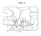
- FIG. 3illustrates an interspinous apparatus according to an exemplary embodiment of the present invention
- FIG. 4illustrates an interspinous apparatus according to the exemplary embodiment of the present invention
- FIG. 5illustrates an interspinous apparatus according to another exemplary embodiment of the present invention
- FIG. 6Aillustrates an interspinous apparatus having stabilizers in a retracted state according to another exemplary embodiment of the present invention
- FIG. 6Billustrates an interspinous apparatus having stabilizers in a deployed state according to the exemplary embodiment of the present invention shown in FIG. 6A ;
- FIG. 7illustrates a locking mechanism according to an exemplary embodiment of the present invention
- FIG. 8illustrates an interspinous apparatus according to another exemplary embodiment of the present invention.
- FIG. 9illustrates an interspinous apparatus according to another exemplary embodiment of the present invention.
- FIG. 10illustrates an interspinous apparatus according to another exemplary embodiment of the present invention.
- FIGS. 11A and 11Billustrate an interspinous apparatus according to another exemplary embodiment of the present invention
- FIGS. 12A and 12Billustrate an interspinous apparatus according to another exemplary embodiment of the present invention.
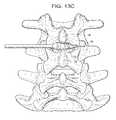
- FIGS. 13A-13Iillustrate a method of performing interspinous distraction according to an exemplary embodiment of the present invention.
- FIGS. 14A-14Hillustrate an interspinous apparatus according to another exemplary embodiment of the present invention.
- the deviceis composed of a device which has a pointed conical shape with embedded screw-shaped (i.e., helical) grooves that permit the passage of the device between the spinous processes of the human spine.
- the deviceis designed to be positioned between two spinous processes. It is placed through the interspinous ligament and below the supra-spinous ligament.
- the grooved conical surfacepermits the device to be screwed into place in a percutaneous or traditional open surgery.
- the deviceis secured between the spinous processes due to a deeper central engagement groove as well as by mechanisms to be described whereby the end(s) of the device are further stabilized. Due to its position within the interspinous ligament and below the supra-spinous ligament, further stability is obtained.
- the devicegradually spreads the spinous processes apart.
- the volume of the spinal canal and vertebral foramenare increased thereby decompressing the spine in cases of spinal stenosis.
- a unique feature of this procedureis that there is no required instrumentation to place the final device into its final position except for a device holding tool (i.e., an insertion driver). Provisional dilation of the spinous processes can be performed if so desired with solid dilators also of conical screw or a smooth semi-conical shape. The depth and pitch and other parameters of a screw configuration can be modified to provide faster insertion, more stable insertion, and positioning of the implant.
- the central groovemay be of a smaller cross-section than the insertion portion and broader to accept the spinous process anatomic region in a stable and consistent manner.
- the devicecan be either solid or cannulated.
- FIG. 1illustrates a high level drawing of an interspinous apparatus 10 according to an exemplary embodiment of the present invention.
- the interspinous apparatus 10includes a distractor 12 , an insertion driver 20 , and a guide wire 24 having a pointed tip 25 .
- the distractor 12has a conical shape which is configured to enable passage of the distractor 12 between two spinous processes 26 of vertebrae such that a gradual distraction between the two spinous processes 26 occurs.
- Each of the distractor 12 and the insertion driver 20have a guide channel which extends through an entire central portion therein configured to accept the guide wire 24 therein.
- the pointed tip 25 of the guide wire 24permits an easier insertion of the guide wire 24 between the two spinous processes 26 .
- the guide wire 24is inserted between the two spinous processes 26 in order to guide the insertion of the distractor 12 , detachably coupled to the insertion driver 20 , between the two spinous processes 26 .
- the distractor 12has a conical shape which is adapted to enable passage of the distractor 12 between two spinous processes 26 that a gradual distraction between the two spinous processes 26 occurs. Due to the conical shape of the distractor 12 , the distractor 12 has an axis of distraction, to be described later, having a constant increasing angle that provides for constant distraction.
- the distractor 12can be composed of any solid or semi solid material including but not limited to poly-ether-ether-ketone (PEEK), titanium, stainless steel, or bone.
- the distractor 12may be composed of but not limited to hydroxyapatite, bone substitutes, a combination of hydroxyapatite and bone cement, CORTOSS, or the like. If the distractor 12 is composed of any material besides bone, motion is preserved due to the rolling effect of the cone in extension and flexion. If the distractor 12 is composed of bone, the device can be used to induce fusion. Thus, the device could also be used to fuse spines depending on what material it is made of.
- the central engagement groove 14can be partially flattened thereby decreasing the rolling effect of the device providing more stability.
- the distractor 12may be used to treat patients who require fusion with or without decompression of the spinal canal and foramen.
- materialssuch as PEEK, steel, titanium, or other alloys could be utilized.
- FIGS. 2A and 2Billustrate a solid dilator 100 that is used before the distractor 12 according to an exemplary embodiment of the present invention.
- the dilator 100includes an insertion portion 113 and a central engagement groove 114 having a proximal end 115 and a distal end 116 .
- the insertion portion 113has a conical shape which tapers from the proximal end 115 of the central engagement groove 114 to a tip 117 and is adapted to enable passage of the dilator 100 between the two spinous processes 26 such that a gradual distraction between the two spinous processes 26 occurs.
- the insertion portion 113has embedded screw-shaped (i.e., helical) grooves 118 which permits the device to be screwed into place in a percutaneous or traditional open surgery.
- the grooves 118include sharp edges 118 A that are configured to incise through a patient's interspinous ligament (not shown).
- the edges 118 Acan serially dilates/spread the interspinous ligament apart. Moreover, the concave grooves 118 dilator keep the interspinous ligament distracted while the next edge 118 A incises the ligament.
- the insertion portion 113an axis of distraction 111 having a constant increasing angle that provides for constant distraction.
- the tip 117 of the insertion portion 113is ungrooved to allow for ease of initial insertions, but may be grooved.
- the tip 119is hollow, showing a portion of the guide channel 119 which extends through the entire central portion of the distractor 112 for accepting the guide wire 124 therein.
- the tip 119also includes a sharp edge 119 A this is configured to cut through the patient's interspinous ligament.
- the central engagement groove 114is adapted to secure the dilator 100 between the two spinous processes 26 such that the two spinous processes 26 rest in the central engagement groove 14 between the proximal end 115 and the distal end 116 .
- FIG. 3illustrates an interspinous apparatus 10 according to another exemplary embodiment of the present invention.
- the distractoris inserted after the dilator 100 is removed and includes an insertion portion 13 and a central engagement groove 14 having a proximal end 15 and a distal end 16 .
- the insertion portion 13has a conical shape which tapers from the proximal end 15 of the central engagement groove 14 to a tip 17 and is adapted to enable passage of the distractor 12 between the two spinous processes 26 such that a gradual distraction between the two spinous processes 26 occurs.
- the insertion portion 13has embedded screw-shaped (i.e., helical) grooves 18 which permits the device to be screwed into place in a percutaneous or traditional open surgery.
- the insertion portion 13an axis of distraction 11 having a constant increasing angle that provides for constant distraction.
- the tip 17 of the insertion portion 13is ungrooved to allow for ease of initial insertions, but may be grooved.
- the tip 19is hollow, showing a portion of the guide channel 19 which extends through the entire central portion of the distractor 12 for accepting the guide wire 24 therein.
- the central engagement groove 14is adapted to secure the distractor 12 between the two spinous processes 26 such that the two spinous processes 26 rest in the central engagement groove 14 between the proximal end 15 and the distal end 16 .
- the interspinous apparatus 10includes the distractor 12 having a rear portion 28 detachably coupled to the insertion driver 20 , and the guide wire 24 .
- the insertion portion 13has a tip 17 which is grooved.
- the distractor 12includes a pair of proximal stabilization wings 30 retracted within a first cavity (not shown) of the distractor 12 and configured to be deployed through a pair of proximal slots 32 disposed on opposite sides of the proximal end 15 of the central engagement groove 14 .
- the stabilization wings 30are deployed after the spinous processes 26 are secured in the central engagement groove 14 to inhibit the distractor 12 from reversing out from between the two spinous processes 26 .
- the distractormay also include a pair of distal stabilization wings 34 retracted within a second cavity (not shown) of the distractor 12 and configured to be deployed through a pair of distal slots 36 disposed on opposite sides of the distal end 16 of the central engagement groove 14 .
- the stabilization wings 34are deployed after the spinous processes 26 are secured in the central engagement groove 14 to inhibit the distractor from being inserted further between the two spinous processes 26 .
- the proximal stabilization wings 30 and the distal stabilization wings 34stabilize the two spinous processes 26 within the central engagement groove 14 and in some embodiments can additionally clamp onto the spinous processes.
- FIG. 4illustrates an interspinous apparatus 10 having the insertion driver 20 decoupled from the rear portion 28 of the distractor 12 and the guide wire 24 removed from the distractor 12 .
- the distractor 12is shown implanted between the two spinous processes 26 and having the proximal stabilization wings 30 and the distal stabilization wings 34 deployed from within the distractor 12 .
- a circular ringcan be slipped over either end of the device and tightened thereby providing stability to the implant (not shown).
- FIG. 5illustrates an interspinous apparatus 10 according to another exemplary embodiment of the present invention.
- the distractor 12includes a stabilization base 35 in the alternative to the distal stabilization wings 34 .
- the stabilization base 35is coupled to the distal end 16 of the central engagement groove 14 and which extends outward from the distractor 12 .
- the stabilization base 35much like the distal stabilization wings 34 , is adapted to inhibit the distractor from being inserted further between the two spinous processes 26 .
- FIGS. 6A and 6Billustrate an interspinous apparatus having stabilizers 30 and 34 in a retracted state and in a deployed state, respectively, according to another exemplary embodiment of the present invention.
- the guide wire 24is disposed within the guide channel 19 , which extends through the entire central portion of the distractor 12 and the insertion driver 20 .
- Each guide channel 19 of the distractor 12 and the insertion driver 20is in alignment with each other.
- the distractor 12includes the pair of proximal stabilization wings 30 retracted within a first cavity 40 of the distractor 12 .
- the proximal stabilization wings 30are configured to be deployed through the pair of proximal slots 32 disposed on opposite sides of the proximal end 15 of the central engagement groove 14 .
- the distractor 12includes the pair of distal stabilization wings 34 retracted within a second cavity 42 of the distractor.
- the distal stabilization wings 34are configured to be deployed through the pair of distal slots 36 disposed on opposite sides of the distal end 16 of the central engagement groove 14 .
- the distractor 12includes a deployment bar 44 disposed therein and detachably coupled to the insertion driver 20 .
- the deployment bar 44is also coupled to each stabilization wing of the proximal stabilization wings 30 and the distal stabilization wings 34 .
- the deployment bar 44is disposed within the guide channel 19 of the distractor 12 and is configured to be slidably switched between an extended position (as shown in FIG. 6A ) and a retracted position (as shown in FIG. 6B ).
- the deployment bar 44when the deployment bar 44 is in the extended position, the deployment bar 44 maintains the proximal stabilization wings 30 and the distal stabilization wings 34 in a retracted state. On the other hand, when deployment bar 44 is in the retracted position, the deployment bar 44 releases the proximal stabilization wings 30 and the distal stabilization wings 34 to a deployed state.
- the deployment bar 44is slidably switched between the extended position and the retracted position by moving the portion of the insertion driver 20 that is detachably coupled to the deployment bar 44 in and out of the distractor 12 .
- the stabilization wings 30 and 34may be locked into their deployed position by a lock configured to engage with the deployment bar 44 .
- the portion of the insertion driver 20 that is detachably coupled to the deployment bar 44may be rotated, and in turn rotating the deployment bar 44 within the distractor 12 to a locked position. Once in a locked state, the insertion driver 20 can be decoupled from the deployment bar 44 and removed from the guide wire 24 .
- FIG. 7illustrates a locking mechanism according to an exemplary embodiment of the present invention.
- a rear portion 46(as shown in FIGS. 6A and 6B ) of the deployment bar 44 has interlocking members 47 which can be rotated clockwise to engage locking slots 48 to lock the deployment bar 44 into place, and thereby, locking the stabilization wings 30 and 34 in the deployed state.
- FIG. 8illustrates an interspinous apparatus according to another exemplary embodiment of the present invention.
- FIG. 8illustrates an alternative mechanism for deploying the proximal stabilization wings 30 and the distal stabilization wings 34 .
- the distractor 12includes an insertion screw driver 50 disposed within the guide channel of the distractor, coupled to the insertion driver 20 and configured to engage a first pair of gears 52 and a second pair of gears 54 .
- Each gear 52 and 54is mechanically coupled to a respective stabilization wing 30 and 34 .
- the insertion screw driver 50is turned within the distractor 12 and engages with the first pair of gears 52 to deploy the pair of proximal stabilization wings 30 from the proximal slots 32 and engages with the second pair of gears 54 to deploy the pair of distal stabilization wings 34 from the distal slots 36 .
- FIG. 9illustrates an interspinous apparatus according to another exemplary embodiment of the present invention.
- FIG. 9illustrates an alternative mechanism for deploying the proximal stabilization wings 30 and the distal stabilization wings 34 .
- Each stabilization wing of the pair of proximal stabilization wings 30 and the pair of distal stabilization wings 34are coupled to the central engagement groove 14 by a pressure mechanism 60 such that the stabilization wings 30 and 34 are deployed when the central engagement groove 14 is pressurized by compression from the two spinous processes 26 upon insertion therebetween.
- the pressure on the central engagement groove 14deploys the stabilization wings 30 and 34 from within the distractor 12 .
- FIG. 10illustrates an interspinous apparatus according to another exemplary embodiment of the present invention.
- FIG. 10illustrates an alternative mechanism for deploying the proximal stabilization wings 30 and the distal stabilization wings 34 .
- the proximal stabilization wings 30 and distal stabilization wingsare balloon O-rings such that the stabilization wings 30 and 34 are deflated in a retracted state and inflated in a deployed state.
- a pump 70 coupled to each of the proximal stabilization wings 30 and distal stabilization wings 34is used to inflate the proximal stabilization wings 30 and the distal stabilization wings to a deployed state 34 .
- the O-ringscan be inflated with either a gas or a liquid to stabilize the implant.
- FIGS. 11A and 11Billustrate an interspinous apparatus according to another exemplary embodiment of the present invention.
- FIGS. 11A and 11Billustrate an alternative mechanism for deploying the proximal stabilization wings 30 .
- FIGS. 11A and 11Billustrate an interspinous apparatus having stabilizers 30 in a retracted state and in a deployed state, respectively, according to another exemplary embodiment of the present invention.
- the insertion portion 13includes a pair of axial rectangular grooves 80 , each disposed oppositely from each other. Within the pair of axial rectangular grooves 80 is disposed the pair of proximal stabilization wings 30 or side wings. Each proximal stabilization wing 30 is disposed within one of the pair of axial rectangular grooves 80 . Furthermore, the proximal stabilization wings 30 are configured to be congruent with a shape of the axial rectangular grooves 80 and with a surface of the insertion portion 13 in an undeployed state as shown in FIG. 11A .
- a surfaces of the proximal stabilization wings 30also have grooves to be congruent the grooved surface of the insertion portion 13 . This enables the distractor 12 to be screwed into place between the two spinous processes 26 when the proximal stabilization wings 30 are undeployed.
- the proximal stabilization wings 30are also configured to be deployed outward from the axial rectangular grooves 80 as shown in FIG. 11B .
- a deployment means 82deploys the pair of proximal stabilization wings 30 from the axial rectangular grooves 80 by pulling the stabilization wings 30 towards the proximal end 15 of the central engagement groove 14 such that such that the stabilization wings 30 open up from the axial rectangular grooves 80 to a vertical position adjacent to the proximal end 15 of the central engagement groove 14 .
- the stabilization wings 30are coupled to the deployment means 82 by a pair of hinges 84 , enabling the stabilization wings 30 to open to a deployed state.
- the distractor 12may also include the stabilization base 35 similar to that shown in FIG. 5 .
- FIGS. 12A and 12Billustrate an interspinous apparatus according to another exemplary embodiment of the present invention.
- FIGS. 12A and 12Billustrate an alternative mechanism for deploying a stabilizer.
- the distractor 12and more particularly, the insertion portion 13 may be composed of differing materials to permit for a collapsing umbrella stabilizing tip to be deployed.
- the insertion portion 13is made of flexible material having a first diameter D 1 at the proximal end 15 of the central engagement groove 14 .
- the insertion portion 13is configured to collapse towards the proximal end of the central engagement groove such that the insertion portion 13 is compressed into a shape having a second diameter D 2 at the proximal end 15 of the central engagement groove 14 larger than the first diameter D 1 after the distractor 12 is implanted to inhibit the distractor 12 from reversing out from between the two spinous processes 26 .
- the distractor 12includes a wire 90 fed through the guide channel 19 and connected to the tip 17 of the insertion portion 13 .
- the tip 17 of the insertion portion 13is adapted to be pulled towards the central engagement groove 14 upon pulling of the wire 90 to collapse the insertion portion 13 .
- the length of portion Bcollapses, while the length of portion A remains constant and rigid.
- the distractor 12may also include the stabilization base 35 similar to that shown in FIG. 5 .
- the stabilization base 35 as described in FIG. 5could be implemented in any of the above exemplary embodiments.
- FIGS. 13A-13Hillustrate a method of performing interspinous distraction according to an exemplary embodiment of the present invention.
- the methodincludes inserting a guide wire 24 having a pointed tip 25 between the two spinous processes 26 ( FIG. 13A ).
- the guide wire 24is configured to guide the insertion of the distractor 12 and the inserting of the insertion driver 20 between the two spinous processes 26 while the insertion driver 20 is coupled to the distractor 12 .
- the distractor 12 and the insertion driver 20each have a guide channel 19 disposed therein configured to accept the guide wire 24 therein.
- Provisional dilation of the spinous processes 26is performed with cannulated conical screw or smooth semi conical shape dilators 100 and 100 , as shown in FIGS. 13B and 13C .
- the first dilator 100is inserted via the guide wire 24 and cuts through the interspinous ligament (not shown) using the sharp edges 117 A, 118 A.
- the dilator 100distracts the spinous processes 26 if the dilator 100 comes into contact with the spinous processes 26 . Then, the first dilator 100 is removed.
- a second dilator 101is inserted via the guide wire 24 .
- the second dilator 101is larger than the first dilator 100 and also cuts through the interspinous ligament. If necessary, several dilators 100 , 101 , etc. can be used until one of the dilators contacts the spinous processes 26 .
- the dilatorscan have slightly increasing outer diameters. For example, a 6 mm, an 8 mm, a 10 mm, a 12 mm, and a 14 mm dilator can be used.
- a distractor of an appropriate sizecan be selected.
- the methodfurther includes inserting the distractor 12 having a conical insertion portion 13 and a central engagement groove 14 between the two spinous processes 26 ( FIG. 13D ).
- the conical insertion portion 13is adapted such that a gradual distraction between the two spinous processes occurs 26 .
- the insertion drive 20acts as a device holding tool for inserting the distractor 12 between the spinous processes 26 .
- FIG. 13Dalso illustrates inserting the insertion driver 20 while coupled to the distractor 12 , the insertion driver 20 being detachably coupled to a rear portion 28 of the distractor 12 .
- the methodfurther includes implanting the distractor 12 between the two spinous processes 26 such that the two spinous processes 26 rest in the central engagement groove 14 between a proximal end 15 and a distal end 16 of the central engagement groove 14 ( FIG. 13E ).
- the methodfurther includes deploying a stabilizer (e.g., stabilization wings 30 and 34 ) which is adapted to be deployed from within the distractor 12 to secure the two spinous processes 26 within the central engagement groove 14 ( FIG. 13F ).
- the stabilizermay also be locked into the deployed state ( FIG. 13F ).
- the methodfurther includes decoupling the insertion driver 20 from the distractor 12 ( FIGS. 13G and 13H ) and removing the insertion driver 20 and the guide wire 24 ( FIG. 13I ).
- FIGS. 14A-14Hillustrate an interspinous apparatus according to another exemplary embodiment of the present invention.
- the apparatuscan be clamped onto the spinous process after being implanted.
- FIG. 14Ashows the features of the apparatus including the insertion portion 143 and guide channel 149 , as explained above, as well as a shaft 146 , which is connected to the insertion portion 143 and passes through the clamp 141 .
- clamp 141is shown in an elliptical shape, however, the clamp 141 could also be circular, rectangular, or any other advantageous shape.
- Teeth 144may be present on the clamp 141 and are configured to create additional friction between the bony mater of the spinous process and the clamp 141 .
- the teeth 144can be sharp and shaped accordingly having a conical, pyramidal or other desired shape.
- FIG. 14Bbetter illustrates the distal end of the apparatus including the distal end of the shaft 146 , and instrument mating feature 147 , where an insertion driver 20 (shown in FIG. 3 ) or any other instrument can be attached for the purpose of implantation, removal, repositioning, etc. of the implant.
- an insertion driver 20shown in FIG. 3
- any other instrumentcan be attached for the purpose of implantation, removal, repositioning, etc. of the implant.
- FIGS. 14C-14Especifically show one particular embodiment of the apparatus 140 where the clamp 141 has two parts: a washer 141 a and a retention nut 141 b.
- the apparatusis shown disassembled into its three main parts: washer 141 a, retention nut portion 141 b, and insertion portion 143 .
- the shaft 146can have a cross-section that is smaller than that of the distal end of the insertion portion 143 .
- the smaller cross-section of the shaft portionis configured to secure the distractor between the two spinous processes such that the two spinous processes rest on the shaft portion.
- the shaft 146may be threaded, as shown, stepped, have a frictioned surface or smooth.
- the apparatus 140After the apparatus 140 has been inserted between the spinous processes, it can be clamped to the spinous processes by advancing the retention nut 141 b, which in this embodiment is in a rotational manner, toward the washer 141 a and the insertion portion 143 . The spinous process becomes clamped between the distal end of the insertion portion 143 and the washer 141 a.
- the retention nut 141 bautomatically locks to the washer 141 a when features 160 and 158 mate and prevent rotation of the washer 141 a and nut 141 b.
- the retention nut 141 bcan be surrounded by one or more retention lips 150 , located on the washer 141 a, configured to have a rim to grasp onto a mating rim of the retention nut 141 b.
- Washer protrusions 160 and the retention nut protrusions 158are meant to mate together to prevent rotation after final tightening of the retention nut 141 b with respect to the shaft 146 . This is necessary to prevent the retention nut 141 b from unscrewing and allowing the assembly to come apart after implantation.
- Protrusions 158 and 160can be any shape including semi-cylindrical, as shown.
- the apparatus 140may contain a full circle of protrusions 158 and 160 around the washer 141 a and retention nut 141 b openings, or the protrusions 158 and 160 strategically placed on only certain portions of the washer 141 a and retention nut 141 b.
- Alternate embodimentscan contain at least one orientation slot 152 which interlocks with at least one orientation key 154 to keep the shaft 146 , and washer 141 a properly aligned.
- there may be a graft cavity 156which is configured to retain biological material, such as a bone graft, to promote bone fusion.
- FIGS. 14F-14Hillustrate the apparatus 140 as it is inserted between two spinous processes.
- the apparatus 140is in its “open” position where the washer 141 a and retention nut 141 b are farther from the insertion portion 143 than when the apparatus 140 is in its “clamped” position as show in FIG. 14H .
- FIG. 14Gshows the apparatus 140 in its final position before the retention nut 141 b is tightened and the clamp 141 a is secured to the spinous process.
Landscapes
- Health & Medical Sciences (AREA)
- Orthopedic Medicine & Surgery (AREA)
- Life Sciences & Earth Sciences (AREA)
- Neurology (AREA)
- Surgery (AREA)
- Heart & Thoracic Surgery (AREA)
- Engineering & Computer Science (AREA)
- Biomedical Technology (AREA)
- Nuclear Medicine, Radiotherapy & Molecular Imaging (AREA)
- Medical Informatics (AREA)
- Molecular Biology (AREA)
- Animal Behavior & Ethology (AREA)
- General Health & Medical Sciences (AREA)
- Public Health (AREA)
- Veterinary Medicine (AREA)
- Prostheses (AREA)
Abstract
Description
Claims (17)
Priority Applications (1)
| Application Number | Priority Date | Filing Date | Title |
|---|---|---|---|
| US13/478,564US8747440B2 (en) | 2008-08-27 | 2012-05-23 | Conical interspinous apparatus and a method of performing interspinous distraction |
Applications Claiming Priority (4)
| Application Number | Priority Date | Filing Date | Title |
|---|---|---|---|
| US9214208P | 2008-08-27 | 2008-08-27 | |
| US12/343,082US8172878B2 (en) | 2008-08-27 | 2008-12-23 | Conical interspinous apparatus and a method of performing interspinous distraction |
| US12/616,245US8192466B2 (en) | 2008-08-27 | 2009-11-11 | Conical interspinous apparatus and a method of performing interspinous distraction |
| US13/478,564US8747440B2 (en) | 2008-08-27 | 2012-05-23 | Conical interspinous apparatus and a method of performing interspinous distraction |
Related Parent Applications (2)
| Application Number | Title | Priority Date | Filing Date |
|---|---|---|---|
| US12/616,245ContinuationUS8192466B2 (en) | 2008-08-27 | 2009-11-11 | Conical interspinous apparatus and a method of performing interspinous distraction |
| US12/616,425ContinuationUS7913967B1 (en) | 2009-11-11 | 2009-11-11 | Adjustable picture-hanger assembly |
Publications (2)
| Publication Number | Publication Date |
|---|---|
| US20120265246A1 US20120265246A1 (en) | 2012-10-18 |
| US8747440B2true US8747440B2 (en) | 2014-06-10 |
Family
ID=42118207
Family Applications (2)
| Application Number | Title | Priority Date | Filing Date |
|---|---|---|---|
| US12/616,245Expired - Fee RelatedUS8192466B2 (en) | 2008-08-27 | 2009-11-11 | Conical interspinous apparatus and a method of performing interspinous distraction |
| US13/478,564Active2029-02-11US8747440B2 (en) | 2008-08-27 | 2012-05-23 | Conical interspinous apparatus and a method of performing interspinous distraction |
Family Applications Before (1)
| Application Number | Title | Priority Date | Filing Date |
|---|---|---|---|
| US12/616,245Expired - Fee RelatedUS8192466B2 (en) | 2008-08-27 | 2009-11-11 | Conical interspinous apparatus and a method of performing interspinous distraction |
Country Status (1)
| Country | Link |
|---|---|
| US (2) | US8192466B2 (en) |
Cited By (2)
| Publication number | Priority date | Publication date | Assignee | Title |
|---|---|---|---|---|
| US20150305785A1 (en)* | 2007-11-02 | 2015-10-29 | Lanx, Inc. | Interspinous implants with deployable wing |
| WO2022155486A1 (en)* | 2021-01-15 | 2022-07-21 | Diffusion RX, Inc. | Joint implant with constant and continuous release of therapeutic agent |
Families Citing this family (50)
| Publication number | Priority date | Publication date | Assignee | Title |
|---|---|---|---|---|
| WO2008070863A2 (en) | 2006-12-07 | 2008-06-12 | Interventional Spine, Inc. | Intervertebral implant |
| US8142479B2 (en) | 2007-05-01 | 2012-03-27 | Spinal Simplicity Llc | Interspinous process implants having deployable engagement arms |
| EP2237748B1 (en) | 2008-01-17 | 2012-09-05 | Synthes GmbH | An expandable intervertebral implant |
| ITPI20080010A1 (en)* | 2008-02-07 | 2009-08-08 | Giuseppe Calvosa | INTERSTEIN VERTEBRAL DISTRACTOR FOR PERCUTANEOUS INSERTION |
| US8936641B2 (en) | 2008-04-05 | 2015-01-20 | DePuy Synthes Products, LLC | Expandable intervertebral implant |
| US9861399B2 (en) | 2009-03-13 | 2018-01-09 | Spinal Simplicity, Llc | Interspinous process implant having a body with a removable end portion |
| US8945184B2 (en)* | 2009-03-13 | 2015-02-03 | Spinal Simplicity Llc. | Interspinous process implant and fusion cage spacer |
| US9757164B2 (en) | 2013-01-07 | 2017-09-12 | Spinal Simplicity Llc | Interspinous process implant having deployable anchor blades |
| US9526620B2 (en) | 2009-03-30 | 2016-12-27 | DePuy Synthes Products, Inc. | Zero profile spinal fusion cage |
| US8328870B2 (en)* | 2009-08-06 | 2012-12-11 | Alphatec Spine, Inc. | Stand-alone interbody fixation system |
| JP2013509959A (en)* | 2009-11-06 | 2013-03-21 | ジンテス ゲゼルシャフト ミット ベシュレンクテル ハフツング | Minimally invasive interspinous spacer implant and method |
| US9393129B2 (en) | 2009-12-10 | 2016-07-19 | DePuy Synthes Products, Inc. | Bellows-like expandable interbody fusion cage |
| US20110160772A1 (en)* | 2009-12-28 | 2011-06-30 | Arcenio Gregory B | Systems and methods for performing spinal fusion |
| US9907560B2 (en) | 2010-06-24 | 2018-03-06 | DePuy Synthes Products, Inc. | Flexible vertebral body shavers |
| US8979860B2 (en) | 2010-06-24 | 2015-03-17 | DePuy Synthes Products. LLC | Enhanced cage insertion device |
| US8623091B2 (en) | 2010-06-29 | 2014-01-07 | DePuy Synthes Products, LLC | Distractible intervertebral implant |
| US8641717B2 (en) | 2010-07-01 | 2014-02-04 | DePuy Synthes Products, LLC | Guidewire insertion methods and devices |
| US8827902B2 (en) | 2010-08-16 | 2014-09-09 | Donald David DIETZE, Jr. | Surgical instrument system and method for providing retraction and vertebral distraction |
| US8702756B2 (en)* | 2010-09-23 | 2014-04-22 | Alphatec Spine, Inc. | Clamping interspinous spacer apparatus and methods of use |
| US9402732B2 (en) | 2010-10-11 | 2016-08-02 | DePuy Synthes Products, Inc. | Expandable interspinous process spacer implant |
| US9498560B2 (en) | 2011-03-04 | 2016-11-22 | Spinefrontier, Inc | Interspinous spacer implant |
| FR2977139B1 (en)* | 2011-06-30 | 2014-08-22 | Ldr Medical | INTER-SPINAL IMPLANT AND IMPLANTATION INSTRUMENT |
| US9717601B2 (en) | 2013-02-28 | 2017-08-01 | DePuy Synthes Products, Inc. | Expandable intervertebral implant, system, kit and method |
| US9522070B2 (en) | 2013-03-07 | 2016-12-20 | Interventional Spine, Inc. | Intervertebral implant |
| US9433445B2 (en) | 2013-03-14 | 2016-09-06 | DePuy Synthes Products, Inc. | Bone anchors and surgical instruments with integrated guide tips |
| US9724137B2 (en)* | 2014-03-19 | 2017-08-08 | Warsaw Orthopedic, Inc. | Surgical instrumentation and method |
| US9855087B2 (en) | 2014-08-04 | 2018-01-02 | DePuy Synthes Products, LLC | Methods and devices for spinal screw insertion |
| KR101577163B1 (en)* | 2014-12-08 | 2015-12-11 | 이민영 | Device for preventing abutment loosening for a dental implant |
| US20160242823A1 (en)* | 2015-02-19 | 2016-08-25 | Mi4Spine, Llc | Interspinous process spacer device including locking ring |
| US11426290B2 (en) | 2015-03-06 | 2022-08-30 | DePuy Synthes Products, Inc. | Expandable intervertebral implant, system, kit and method |
| FR3048176A1 (en) | 2016-02-26 | 2017-09-01 | Ldr Medical | SPINAL ARTHRODESIS IMPLANT SYSTEM |
| US11510710B2 (en)* | 2016-04-14 | 2022-11-29 | Spinal Simplicity, Llc | Locking system for interspinous implant insertion instrument |
| US20220226027A1 (en)* | 2016-04-14 | 2022-07-21 | Spinal Simplicity, Llc | Interspinous implant insertion instrument with wing actuation tool |
| EP3474784A2 (en) | 2016-06-28 | 2019-05-01 | Eit Emerging Implant Technologies GmbH | Expandable and angularly adjustable intervertebral cages with articulating joint |
| US11510788B2 (en) | 2016-06-28 | 2022-11-29 | Eit Emerging Implant Technologies Gmbh | Expandable, angularly adjustable intervertebral cages |
| US10398563B2 (en) | 2017-05-08 | 2019-09-03 | Medos International Sarl | Expandable cage |
| US11344424B2 (en) | 2017-06-14 | 2022-05-31 | Medos International Sarl | Expandable intervertebral implant and related methods |
| US10433883B2 (en) | 2017-06-27 | 2019-10-08 | Medos International Sarl | Spinal screw insertion devices and methods |
| US10779872B2 (en) | 2017-11-02 | 2020-09-22 | Medos International Sarl | Bone anchor insertion instruments and methods |
| US10864029B2 (en)* | 2018-01-26 | 2020-12-15 | West End Bay Partners, Llc | Sacroiliac joint stabilization and fixation devices and related methods |
| US11446156B2 (en) | 2018-10-25 | 2022-09-20 | Medos International Sarl | Expandable intervertebral implant, inserter instrument, and related methods |
| US11123113B2 (en) | 2019-06-13 | 2021-09-21 | Medos International Sarl | Screw inserter instruments and methods |
| US11224472B2 (en) | 2019-06-13 | 2022-01-18 | Medos International Sarl | Screw inserter instruments and methods |
| FR3098385B1 (en) | 2019-07-08 | 2023-05-12 | Innospina Sarl | Interspinous vertebral implant and associated placement ancillary |
| US11426286B2 (en) | 2020-03-06 | 2022-08-30 | Eit Emerging Implant Technologies Gmbh | Expandable intervertebral implant |
| US11850160B2 (en) | 2021-03-26 | 2023-12-26 | Medos International Sarl | Expandable lordotic intervertebral fusion cage |
| US11752009B2 (en) | 2021-04-06 | 2023-09-12 | Medos International Sarl | Expandable intervertebral fusion cage |
| US11766280B1 (en)* | 2022-04-08 | 2023-09-26 | Spinal Simplicity, Llc | Interspinous implant insertion instrument with wing actuation tool |
| US12133664B2 (en) | 2022-12-13 | 2024-11-05 | Spinal Simplicity, Llc | Medical implant |
| CN119700329B (en)* | 2025-02-24 | 2025-05-23 | 浙江科惠医疗器械股份有限公司 | Periosteum stretching device for skull |
Citations (4)
| Publication number | Priority date | Publication date | Assignee | Title |
|---|---|---|---|---|
| US20060265066A1 (en)* | 2005-03-21 | 2006-11-23 | St. Francis Medical Technologies, Inc. | Interspinous process implant having a thread-shaped wing and method of implantation |
| US20080243250A1 (en)* | 2007-03-26 | 2008-10-02 | Seifert Jody L | Lateral Spinous Process Spacer |
| US20090326581A1 (en)* | 2006-03-24 | 2009-12-31 | Geoffrey Harrison Galley | Expandable spacing means for insertion between spinous processes of adjacent vertebrae |
| US20100234889A1 (en)* | 2009-03-13 | 2010-09-16 | Harold Hess | Interspinous Process Implant and Fusion Cage Spacer |
- 2009
- 2009-11-11USUS12/616,245patent/US8192466B2/ennot_activeExpired - Fee Related
- 2012
- 2012-05-23USUS13/478,564patent/US8747440B2/enactiveActive
Patent Citations (4)
| Publication number | Priority date | Publication date | Assignee | Title |
|---|---|---|---|---|
| US20060265066A1 (en)* | 2005-03-21 | 2006-11-23 | St. Francis Medical Technologies, Inc. | Interspinous process implant having a thread-shaped wing and method of implantation |
| US20090326581A1 (en)* | 2006-03-24 | 2009-12-31 | Geoffrey Harrison Galley | Expandable spacing means for insertion between spinous processes of adjacent vertebrae |
| US20080243250A1 (en)* | 2007-03-26 | 2008-10-02 | Seifert Jody L | Lateral Spinous Process Spacer |
| US20100234889A1 (en)* | 2009-03-13 | 2010-09-16 | Harold Hess | Interspinous Process Implant and Fusion Cage Spacer |
Cited By (5)
| Publication number | Priority date | Publication date | Assignee | Title |
|---|---|---|---|---|
| US20150305785A1 (en)* | 2007-11-02 | 2015-10-29 | Lanx, Inc. | Interspinous implants with deployable wing |
| US9750544B2 (en)* | 2007-11-02 | 2017-09-05 | Zimmer Biomet Spine, Inc. | Interspinous implants with deployable wing |
| US10561447B2 (en) | 2012-12-31 | 2020-02-18 | Zimmer Biomet Spine, Inc. | Interspinous implants with deployable wing |
| WO2022155486A1 (en)* | 2021-01-15 | 2022-07-21 | Diffusion RX, Inc. | Joint implant with constant and continuous release of therapeutic agent |
| US11980701B2 (en) | 2021-01-15 | 2024-05-14 | Diffusion RX, Inc. | Joint implant with constant and continuous release of therapeutic agent |
Also Published As
| Publication number | Publication date |
|---|---|
| US20120265246A1 (en) | 2012-10-18 |
| US20100106191A1 (en) | 2010-04-29 |
| US8192466B2 (en) | 2012-06-05 |
Similar Documents
| Publication | Publication Date | Title |
|---|---|---|
| US8747440B2 (en) | Conical interspinous apparatus and a method of performing interspinous distraction | |
| US8518083B2 (en) | Conical interspinous apparatus and a method of performing interspinous distraction | |
| US10918498B2 (en) | Devices and methods for inter-vertebral orthopedic device placement | |
| US10709481B2 (en) | Systems and methods for posterior dynamic stabilization of the spine | |
| EP1819287B1 (en) | System for stabilizing the motion or adjusting the position of the spine | |
| US9907579B2 (en) | Interspinous spacer assembly | |
| US10039576B2 (en) | Systems and methods for posterior dynamic stabilization of the spine | |
| US8317864B2 (en) | Systems and methods for posterior dynamic stabilization of the spine | |
| CN100518682C (en) | Expandable percutaneous sheath | |
| US20080147192A1 (en) | Percutaneous spinal implants and methods | |
| US20070093846A1 (en) | Apparatus and methods for vertebral augmentation | |
| US20100036495A1 (en) | Device and method for treating spine | |
| WO2009143496A1 (en) | Devices and methods for spinal reduction, displacement and resection | |
| KR20120001759A (en) | Pulmonary Implant and Fusion Cage Spacer | |
| JP2009511198A (en) | Vertebral augmentation device and method | |
| ES2623851T3 (en) | Conical interspinous apparatus | |
| HK1144543A (en) | Conical interspinous apparatus and a method of performing interspinous distraction | |
| HK1170140B (en) | Interspinous process implant and fusion cage spacer |
Legal Events
| Date | Code | Title | Description |
|---|---|---|---|
| AS | Assignment | Owner name:ALPHATEC SPINE, INC., CALIFORNIA Free format text:ASSIGNMENT OF ASSIGNORS INTEREST;ASSIGNORS:YUE, JAMES J., DR.;ARAMBULA, JARED;GAMBOA, CHRISTIAN;SIGNING DATES FROM 20090106 TO 20091217;REEL/FRAME:028463/0932 | |
| AS | Assignment | Owner name:DEERFIELD PRIVATE DESIGN INTERNATIONAL II, L.P., N Free format text:SECURITY INTEREST;ASSIGNORS:ALPHATEC HOLDINGS, INC.;ALPHATEC SPINE, INC.;ALPHATEC INTERNATIONAL LLC;AND OTHERS;REEL/FRAME:032551/0037 Effective date:20140317 Owner name:DEERFIELD SPECIAL SITUATIONS INTERNATIONAL MASTER Free format text:SECURITY INTEREST;ASSIGNORS:ALPHATEC HOLDINGS, INC.;ALPHATEC SPINE, INC.;ALPHATEC INTERNATIONAL LLC;AND OTHERS;REEL/FRAME:032551/0037 Effective date:20140317 Owner name:DEERFIELD SPECIAL SITUATIONS FUND, L.P., NEW YORK Free format text:SECURITY INTEREST;ASSIGNORS:ALPHATEC HOLDINGS, INC.;ALPHATEC SPINE, INC.;ALPHATEC INTERNATIONAL LLC;AND OTHERS;REEL/FRAME:032551/0037 Effective date:20140317 Owner name:DEERFIELD PRIVATE DESIGN FUND II, L.P., NEW YORK Free format text:SECURITY INTEREST;ASSIGNORS:ALPHATEC HOLDINGS, INC.;ALPHATEC SPINE, INC.;ALPHATEC INTERNATIONAL LLC;AND OTHERS;REEL/FRAME:032551/0037 Effective date:20140317 | |
| STCF | Information on status: patent grant | Free format text:PATENTED CASE | |
| AS | Assignment | Owner name:MIDCAP FINANCIAL LLC, MARYLAND Free format text:SECURITY INTEREST;ASSIGNOR:ALPHATEC HOLDINGS, INC; ALPHATEC SPINE, INC; ALPHATEC INTERNATIONAL LLC; ALPHATEC PACIFIC, INC.;REEL/FRAME:036515/0808 Effective date:20150710 | |
| AS | Assignment | Owner name:ALPHATEC SPINE, INC., CALIFORNIA Free format text:RELEASE BY SECURED PARTY;ASSIGNORS:DEERFIELD PRIVATE DESIGN FUND II, L.P.;DEERFIELD PRIVATE DESIGN INTERNATIONAL II, L.P.;DEERFIELD SPECIAL SITUATIONS FUND, L.P.;AND OTHERS;REEL/FRAME:039950/0360 Effective date:20160901 Owner name:ALPHATEC INTERNATIONAL LLC, CALIFORNIA Free format text:RELEASE BY SECURED PARTY;ASSIGNORS:DEERFIELD PRIVATE DESIGN FUND II, L.P.;DEERFIELD PRIVATE DESIGN INTERNATIONAL II, L.P.;DEERFIELD SPECIAL SITUATIONS FUND, L.P.;AND OTHERS;REEL/FRAME:039950/0360 Effective date:20160901 Owner name:ALPHATEC HOLDINGS, INC., CALIFORNIA Free format text:RELEASE BY SECURED PARTY;ASSIGNORS:DEERFIELD PRIVATE DESIGN FUND II, L.P.;DEERFIELD PRIVATE DESIGN INTERNATIONAL II, L.P.;DEERFIELD SPECIAL SITUATIONS FUND, L.P.;AND OTHERS;REEL/FRAME:039950/0360 Effective date:20160901 Owner name:ALPHATEC PACIFIC, INC., CALIFORNIA Free format text:RELEASE BY SECURED PARTY;ASSIGNORS:DEERFIELD PRIVATE DESIGN FUND II, L.P.;DEERFIELD PRIVATE DESIGN INTERNATIONAL II, L.P.;DEERFIELD SPECIAL SITUATIONS FUND, L.P.;AND OTHERS;REEL/FRAME:039950/0360 Effective date:20160901 | |
| AS | Assignment | Owner name:GLOBUS MEDICAL, INC., PENNSYLVANIA Free format text:INTELLECTUAL PROPERTY SECURITY AGREEMENT;ASSIGNORS:ALPHATEC HOLDINGS, INC.;ALPHATEC SPINE, INC.;REEL/FRAME:040108/0202 Effective date:20160901 | |
| AS | Assignment | Owner name:MIDCAP FINANCIAL LLC, MARYLAND Free format text:CORRECTIVE ASSIGNMENT TO CORRECT THE INADVERTENT INCLUSION OF APP. NO. 13252427 IN THE SECURITY INTEREST RECORDATION PREVIOUSLY RECORDED ON REEL 036515 FRAME 0808. ASSIGNOR(S) HEREBY CONFIRMS THE SECURITY INTEREST RECORDED AS TO THE PROPERTIES BELOW;ASSIGNORS:ALPHATEC HOLDINGS, INC.;ALPHATEC SPINE, INC.;ALPHATEC INTERNATIONAL LLC;AND OTHERS;REEL/FRAME:040170/0945 Effective date:20150710 | |
| AS | Assignment | Owner name:MIDCAP FINANCIAL LLC, MARYLAND Free format text:CORRECTIVE ASSIGNMENT TO CORRECT THE INADVERTENT INCLUSION OF APP. NO. 13252427 IN THE CORRECTIVE ASSIGNMENT PREVIOUSLY RECORDED ON REEL 039537 FRAME 0252. ASSIGNOR(S) HEREBY CONFIRMS THE SECURITY INTEREST;ASSIGNORS:ALPHATEC HOLDINGS INC.;ALPHATEC SPINE, INC.;ALPHATEC INTERNATIONAL LLC;AND OTHERS;REEL/FRAME:040649/0808 Effective date:20150710 | |
| AS | Assignment | Owner name:MIDCAP FINANCIAL LLC, MARYLAND Free format text:CORRECTIVE ASSIGNMENT TO CORRECT THE INCORRECT SERIAL NUMBER 13060424 PREVIOUSLY RECORDED AT REEL: 036515 FRAME: 0808. ASSIGNOR(S) HEREBY CONFIRMS THE SECURITY INTEREST;ASSIGNORS:ALPHATEC HOLDINGS, INC.;ALPHATEC SPINE, INC.;ALPHATEC INTERNATIONAL LLC;AND OTHERS;REEL/FRAME:042214/0845 Effective date:20150710 | |
| MAFP | Maintenance fee payment | Free format text:PAYMENT OF MAINTENANCE FEE, 4TH YR, SMALL ENTITY (ORIGINAL EVENT CODE: M2551) Year of fee payment:4 | |
| AS | Assignment | Owner name:ALPHATEC HOLDINGS, INC., CALIFORNIA Free format text:RELEASE BY SECURED PARTY;ASSIGNOR:GLOBUS MEDICAL, INC.;REEL/FRAME:047485/0084 Effective date:20181107 Owner name:ALPHATEC SPINE, INC., CALIFORNIA Free format text:RELEASE BY SECURED PARTY;ASSIGNOR:GLOBUS MEDICAL, INC.;REEL/FRAME:047485/0084 Effective date:20181107 | |
| AS | Assignment | Owner name:SQUADRON MEDICAL FINANCE SOLUTIONS LLC, CONNECTICUT Free format text:SECURITY INTEREST;ASSIGNORS:ALPHATEC HOLDINGS, INC.;ALPHATEC SPINE, INC.;REEL/FRAME:047494/0562 Effective date:20181106 Owner name:SQUADRON MEDICAL FINANCE SOLUTIONS LLC, CONNECTICU Free format text:SECURITY INTEREST;ASSIGNORS:ALPHATEC HOLDINGS, INC.;ALPHATEC SPINE, INC.;REEL/FRAME:047494/0562 Effective date:20181106 | |
| AS | Assignment | Owner name:ALPHATEC HOLDINGS, INC., CALIFORNIA Free format text:RELEASE OF SECURITY INTEREST IN PATENT COLLATERAL AT REEL/FRAME NO. 47494/0562;ASSIGNOR:SQUADRON MEDICAL FINANCE SOLUTIONS LLC;REEL/FRAME:057177/0687 Effective date:20210804 Owner name:ALPHATEC SPINE, INC., CALIFORNIA Free format text:RELEASE OF SECURITY INTEREST IN PATENT COLLATERAL AT REEL/FRAME NO. 47494/0562;ASSIGNOR:SQUADRON MEDICAL FINANCE SOLUTIONS LLC;REEL/FRAME:057177/0687 Effective date:20210804 | |
| FEPP | Fee payment procedure | Free format text:ENTITY STATUS SET TO UNDISCOUNTED (ORIGINAL EVENT CODE: BIG.); ENTITY STATUS OF PATENT OWNER: LARGE ENTITY | |
| MAFP | Maintenance fee payment | Free format text:PAYMENT OF MAINTENANCE FEE, 8TH YEAR, LARGE ENTITY (ORIGINAL EVENT CODE: M1552); ENTITY STATUS OF PATENT OWNER: LARGE ENTITY Year of fee payment:8 | |
| AS | Assignment | Owner name:ALPHATEC PACIFIC, INC., CALIFORNIA Free format text:RELEASE OF SECURITY INTEREST IN INTELLECTUAL PROPERTY AT REEL/FRAME NO. 036515/0808;ASSIGNOR:MIDCAP FUNDING IV TRUST, AS SUCCESSOR-IN-INTEREST TO MIDCAP FINANCIAL, LLC;REEL/FRAME:061554/0608 Effective date:20220922 Owner name:ALPHATEC INTERNATIONAL LLC, CALIFORNIA Free format text:RELEASE OF SECURITY INTEREST IN INTELLECTUAL PROPERTY AT REEL/FRAME NO. 036515/0808;ASSIGNOR:MIDCAP FUNDING IV TRUST, AS SUCCESSOR-IN-INTEREST TO MIDCAP FINANCIAL, LLC;REEL/FRAME:061554/0608 Effective date:20220922 Owner name:ALPHATEC SPINE, INC., CALIFORNIA Free format text:RELEASE OF SECURITY INTEREST IN INTELLECTUAL PROPERTY AT REEL/FRAME NO. 036515/0808;ASSIGNOR:MIDCAP FUNDING IV TRUST, AS SUCCESSOR-IN-INTEREST TO MIDCAP FINANCIAL, LLC;REEL/FRAME:061554/0608 Effective date:20220922 Owner name:ALPHATEC HOLDINGS, INC., CALIFORNIA Free format text:RELEASE OF SECURITY INTEREST IN INTELLECTUAL PROPERTY AT REEL/FRAME NO. 036515/0808;ASSIGNOR:MIDCAP FUNDING IV TRUST, AS SUCCESSOR-IN-INTEREST TO MIDCAP FINANCIAL, LLC;REEL/FRAME:061554/0608 Effective date:20220922 | |
| AS | Assignment | Owner name:MIDCAP FUNDING IV TRUST, MARYLAND Free format text:SECURITY INTEREST;ASSIGNORS:ALPHATEC SPINE, INC.;SAFEOP SURGICAL, INC.;REEL/FRAME:062310/0001 Effective date:20230106 | |
| AS | Assignment | Owner name:WILMINGTON TRUST, NATIONAL ASSOCIATION, DELAWARE Free format text:SECURITY INTEREST;ASSIGNORS:ALPHATEC SPINE, INC.;SAFEOP SURGICAL, INC.;REEL/FRAME:062681/0020 Effective date:20230106 |