US8747170B2 - Connector assemblies and systems and methods for forming disconnectable joint assemblies - Google Patents
Connector assemblies and systems and methods for forming disconnectable joint assembliesDownload PDFInfo
- Publication number
- US8747170B2 US8747170B2US13/565,687US201213565687AUS8747170B2US 8747170 B2US8747170 B2US 8747170B2US 201213565687 AUS201213565687 AUS 201213565687AUS 8747170 B2US8747170 B2US 8747170B2
- Authority
- US
- United States
- Prior art keywords
- coupling
- conductor
- interlock
- connectors
- fastener
- Prior art date
- Legal status (The legal status is an assumption and is not a legal conclusion. Google has not performed a legal analysis and makes no representation as to the accuracy of the status listed.)
- Active, expires
Links
- 238000000034methodMethods0.000titleclaimsdescription13
- 230000000712assemblyEffects0.000titledescription7
- 238000000429assemblyMethods0.000titledescription7
- 230000008878couplingEffects0.000claimsabstractdescription151
- 238000010168coupling processMethods0.000claimsabstractdescription151
- 238000005859coupling reactionMethods0.000claimsabstractdescription151
- 239000004020conductorSubstances0.000claimsabstractdescription70
- 230000013011matingEffects0.000claimsdescription4
- 238000006073displacement reactionMethods0.000claims3
- 239000000463materialSubstances0.000description16
- 239000004065semiconductorSubstances0.000description12
- RYGMFSIKBFXOCR-UHFFFAOYSA-NCopperChemical compound[Cu]RYGMFSIKBFXOCR-UHFFFAOYSA-N0.000description6
- 229910052802copperInorganic materials0.000description6
- 239000010949copperSubstances0.000description6
- 238000009413insulationMethods0.000description6
- 229920002943EPDM rubberPolymers0.000description5
- 230000007935neutral effectEffects0.000description5
- 238000005192partitionMethods0.000description5
- 229920000181Ethylene propylene rubberPolymers0.000description4
- 230000000295complement effectEffects0.000description4
- 239000000758substrateSubstances0.000description4
- 229910001369BrassInorganic materials0.000description3
- 229910052782aluminiumInorganic materials0.000description3
- XAGFODPZIPBFFR-UHFFFAOYSA-NaluminiumChemical compound[Al]XAGFODPZIPBFFR-UHFFFAOYSA-N0.000description3
- 230000008901benefitEffects0.000description3
- 239000010951brassSubstances0.000description3
- 239000006229carbon blackSubstances0.000description3
- 238000005266castingMethods0.000description3
- 229920001971elastomerPolymers0.000description3
- 239000013536elastomeric materialSubstances0.000description3
- 238000003754machiningMethods0.000description3
- 229910052751metalInorganic materials0.000description3
- 239000002184metalSubstances0.000description3
- 238000000465mouldingMethods0.000description3
- 239000004944Liquid Silicone RubberSubstances0.000description2
- 230000005540biological transmissionEffects0.000description2
- 229920003020cross-linked polyethylenePolymers0.000description2
- 239000004703cross-linked polyethyleneSubstances0.000description2
- 239000000806elastomerSubstances0.000description2
- 238000003780insertionMethods0.000description2
- 230000037431insertionEffects0.000description2
- 238000012986modificationMethods0.000description2
- 230000004048modificationEffects0.000description2
- 230000008439repair processEffects0.000description2
- 229920002379silicone rubberPolymers0.000description2
- 230000007704transitionEffects0.000description2
- 239000004698PolyethyleneSubstances0.000description1
- 241000872198Serjania polyphyllaSpecies0.000description1
- 229910000831SteelInorganic materials0.000description1
- 230000009286beneficial effectEffects0.000description1
- 230000015556catabolic processEffects0.000description1
- 238000006731degradation reactionMethods0.000description1
- 238000005553drillingMethods0.000description1
- 230000005684electric fieldEffects0.000description1
- 238000009434installationMethods0.000description1
- 239000013521masticSubstances0.000description1
- 229920001084poly(chloroprene)Polymers0.000description1
- -1polyethylenePolymers0.000description1
- 229920000573polyethylenePolymers0.000description1
- 229920001296polysiloxanePolymers0.000description1
- 239000000565sealantSubstances0.000description1
- 239000007787solidSubstances0.000description1
- 239000010959steelSubstances0.000description1
Images


Classifications
- H—ELECTRICITY
- H01—ELECTRIC ELEMENTS
- H01R—ELECTRICALLY-CONDUCTIVE CONNECTIONS; STRUCTURAL ASSOCIATIONS OF A PLURALITY OF MUTUALLY-INSULATED ELECTRICAL CONNECTING ELEMENTS; COUPLING DEVICES; CURRENT COLLECTORS
- H01R4/00—Electrically-conductive connections between two or more conductive members in direct contact, i.e. touching one another; Means for effecting or maintaining such contact; Electrically-conductive connections having two or more spaced connecting locations for conductors and using contact members penetrating insulation
- H01R4/28—Clamped connections, spring connections
- H01R4/30—Clamped connections, spring connections utilising a screw or nut clamping member
- H01R4/36—Conductive members located under tip of screw
- H—ELECTRICITY
- H01—ELECTRIC ELEMENTS
- H01R—ELECTRICALLY-CONDUCTIVE CONNECTIONS; STRUCTURAL ASSOCIATIONS OF A PLURALITY OF MUTUALLY-INSULATED ELECTRICAL CONNECTING ELEMENTS; COUPLING DEVICES; CURRENT COLLECTORS
- H01R11/00—Individual connecting elements providing two or more spaced connecting locations for conductive members which are, or may be, thereby interconnected, e.g. end pieces for wires or cables supported by the wire or cable and having means for facilitating electrical connection to some other wire, terminal, or conductive member, blocks of binding posts
- H01R11/11—End pieces or tapping pieces for wires, supported by the wire and for facilitating electrical connection to some other wire, terminal or conductive member
- H—ELECTRICITY
- H01—ELECTRIC ELEMENTS
- H01R—ELECTRICALLY-CONDUCTIVE CONNECTIONS; STRUCTURAL ASSOCIATIONS OF A PLURALITY OF MUTUALLY-INSULATED ELECTRICAL CONNECTING ELEMENTS; COUPLING DEVICES; CURRENT COLLECTORS
- H01R13/00—Details of coupling devices of the kinds covered by groups H01R12/70 or H01R24/00 - H01R33/00
- H01R13/62—Means for facilitating engagement or disengagement of coupling parts or for holding them in engagement
- H01R13/621—Bolt, set screw or screw clamp
- H01R13/6215—Bolt, set screw or screw clamp using one or more bolts
- H—ELECTRICITY
- H01—ELECTRIC ELEMENTS
- H01R—ELECTRICALLY-CONDUCTIVE CONNECTIONS; STRUCTURAL ASSOCIATIONS OF A PLURALITY OF MUTUALLY-INSULATED ELECTRICAL CONNECTING ELEMENTS; COUPLING DEVICES; CURRENT COLLECTORS
- H01R13/00—Details of coupling devices of the kinds covered by groups H01R12/70 or H01R24/00 - H01R33/00
- H01R13/64—Means for preventing incorrect coupling
- Y—GENERAL TAGGING OF NEW TECHNOLOGICAL DEVELOPMENTS; GENERAL TAGGING OF CROSS-SECTIONAL TECHNOLOGIES SPANNING OVER SEVERAL SECTIONS OF THE IPC; TECHNICAL SUBJECTS COVERED BY FORMER USPC CROSS-REFERENCE ART COLLECTIONS [XRACs] AND DIGESTS
- Y10—TECHNICAL SUBJECTS COVERED BY FORMER USPC
- Y10T—TECHNICAL SUBJECTS COVERED BY FORMER US CLASSIFICATION
- Y10T29/00—Metal working
- Y10T29/49—Method of mechanical manufacture
- Y10T29/49002—Electrical device making
- Y10T29/49117—Conductor or circuit manufacturing
- Y10T29/49194—Assembling elongated conductors, e.g., splicing, etc.
- Y10T29/49195—Assembling elongated conductors, e.g., splicing, etc. with end-to-end orienting
Definitions
- the present inventionrelates to electrical cables and connections and, more particularly, to connector assemblies for disconnectable joints.
- Disconnectable joint assembliesare commonly used in electrical power transmission networks in urban environments. Electrical power cables to be spliced are each provided with a cable termination lug or connector. Each cable termination lug is disconnectably and reconnectably secured to the other by a bolt, for example.
- Disconnectable joint assemblies as described aboveare useful in urban network applications where a utility may need the ability to disconnect a joint to sectionalize a piece of cable for repair, for example.
- a bad or damaged cablemay be disconnected from the joint assembly to remove the cable from the circuit in a quick and efficient manner, and then reconnected to the joint assembly after the repair is made.
- joint sleeve systemsIn order to protect the joint, cable, and cable terminal lugs from the environment (e.g., moisture) and to protect technicians from the electrically energized components, joint sleeve systems are employed.
- a disconnectable joint system for disconnectably electrically and mechanically connecting first and second electrical each including a respective electrical conductorincludes a first connector, a second connector, and a coupling fastener.
- the first connectordefines a first conductor bore and a first coupling portion.
- the first conductor boreis configured to receive the conductor of the first cable.
- the first coupling portionincludes a first coupling bore defined therein, and a first integral interlock feature.
- the second connectordefines a second conductor bore and a second coupling portion.
- the second conductor boreis configured to receive the conductor of the second cable.
- the second coupling portionincludes a second coupling bore defined therein, and a second integral interlock feature.
- the first and second coupling portionsare mateable in an interlocked position wherein the first and second interlock features are interlocked with one another and the first and second coupling bores are substantially aligned.
- the coupling fastenercan be inserted through the first and second coupling bores and tightened to securely couple the first and second connectors to one another.
- the first and second connectorscan be separated upon removal of the coupling fastener.
- the first connectordefines a first conductor bore and a first coupling portion.
- the first conductor boreis configured to receive the conductor of the first cable.
- the first coupling portionincludes a first coupling bore defined therein, and a first integral interlock feature.
- the second connectordefines a second conductor bore and a second coupling portion.
- the second conductor boreis configured to receive the conductor of the second cable.
- the second coupling portionincludes a second coupling bore defined therein, and a second integral interlock feature.
- the first and second coupling portionsare mated in an interlocked position wherein the first and second interlock features are interlocked with one another and the first and second coupling bores are substantially aligned.
- the coupling fastenerextends through the first and second coupling bores and securely couples the first and second connectors to one another. The first and second connectors can be separated upon removal of the coupling fastener.
- a method for disconnectably electrically and mechanically connecting first and second electrical cables each including a respective electrical conductorincludes providing a disconnectable joint assembly including a first connector, a second connector, and a coupling fastener.
- the first connectordefines a first conductor bore and a first coupling portion.
- the first conductor boreis configured to receive the conductor of the first cable.
- the first coupling portionincludes a first coupling bore defined therein, and a first integral interlock feature.
- the second connectordefines a second conductor bore and a second coupling portion.
- the second conductor boreis configured to receive the conductor of the second cable.
- the second coupling portionincludes a second coupling bore defined therein, and a second integral interlock feature.
- the methodfurther includes: mating the first and second coupling portions in an interlocked position wherein the first and second interlock features are interlocked with one another and the first and second coupling bores are substantially aligned; and with the first and second coupling portions in the interlocked position, inserting the coupling fastener through the first and second coupling bores and tightening the coupling fastener to securely couple the first and second connectors to one another.
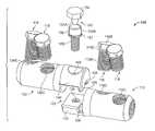
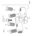
- FIGS. 1 and 2are exploded, perspective views of a disconnectable joint system according to embodiments of the present invention.
- FIG. 3is a perspective view of a disconnectable joint assembly according to embodiments of the present invention and assembled using the joint system of FIG. 1 .
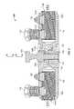
- FIG. 4is a cross-sectional view of the joint assembly of FIG. 3 taken along the lines 4 - 4 of FIG. 3 .
- FIG. 5is a perspective view of a first connector forming a part of the joint assembly of FIG. 3 .
- FIG. 6is a perspective view of a second connector forming a part of the joint assembly of FIG. 3 .
- FIG. 7is a perspective view of an exemplary electrical cable for use with the joint assembly of FIG. 3 .
- FIG. 8is a cross-sectional view of a covered connection including the joint assembly of FIG. 3 .
- FIG. 9is a cross-sectional view of a covered connection including a disconnectable joint assembly according to further embodiments of the present invention.
- FIG. 10is a perspective view of an alternative coupling bolt for use in the joint assembly of FIG. 3 .
- first, second, etc.may be used herein to describe various elements, components, regions, layers and/or sections, these elements, components, regions, layers and/or sections should not be limited by these terms. These terms are only used to distinguish one element, component, region, layer or section from another region, layer or section. Thus, a first element, component, region, layer or section discussed below could be termed a second element, component, region, layer or section without departing from the teachings of the present invention.
- spatially relative termssuch as “beneath”, “below”, “lower”, “above”, “upper” and the like, may be used herein for ease of description to describe one element or feature's relationship to another element(s) or feature(s) as illustrated in the figures. It will be understood that the spatially relative terms are intended to encompass different orientations of the device in use or operation in addition to the orientation depicted in the figures. For example, if the device in the figures is turned over, elements described as “below” or “beneath” other elements or features would then be oriented “above” the other elements or features. Thus, the exemplary term “below” can encompass both an orientation of above and below. The device may be otherwise oriented (rotated 90° or at other orientations) and the spatially relative descriptors used herein interpreted accordingly.
- monolithicmeans an object that is a single, unitary piece formed or composed of a material without joints or seams.
- cold-appliedor “cold-applied cover” means that the cover or component can be assembled or installed about a substrate (e.g., a cable) without requiring the use of applied heat at the time of installation.
- cold shrinkor “cold shrink cover” means that the cover or component can be shrunk or contracted about a substrate (e.g., a cable) without requiring the use of applied heat.
- a disconnectable joint system 105according to some embodiments of the present invention is shown therein.
- the system 105can be used to construct a disconnectable joint assembly 100 (hereinafter, “the joint assembly 100 ”) according to some embodiments of the present invention.
- the joint assembly 100can be used to form a mechanical and electrical connection or joint 10 between two power cables 40 , 50 , for example.
- the connection 10is provided with a cover or cover assembly 170 to form an environmentally protected connection.
- the system 105includes a first connector 110 , a second connector 130 , and a coupling fastener 150 .
- the coupling fastener 150is a threaded fastener and, in some embodiments, is a bolt.
- the connectors 110 , 130incorporate an integral alignment and interlock system 102 as discussed below.
- the connectors 110 , 130are adapted and configured to provide mechanical and electrical connections between each connector 110 , 130 and a respective cable 40 , 50 and between each other, as discussed hereinbelow.
- the first connector 110is a shear bolt connector including an electrically conductive (e.g., metal) connector body 112 and one or more (as shown, two) clamp threaded fasteners or bolts 118 .
- the connector body 112has axially opposed ends 112 A and 112 B defining a connector axis A-A.
- the connector body 112includes a cable or main portion 114 and a coupling portion, tab, arm or lug 120 extending to the end 112 B, A conductor bore 116 A is defined in the main portion 114 , communicates with a cable receiving opening 116 B on the end 112 A, and extends generally coaxially with the axis A-A.
- Threaded bolt bores 116 Cextend radially through the main portion 114 and intersect the conductor bore 116 A.
- the conductor bore 116 Ais configured to receive a terminal segment of the cable conductor 40 .
- the main portion 114has an end face 114 B and a generally cylindrical outer surface 114 A.
- Each conductor clamp bolt 118includes a shank 118 A, a head 118 B, and a shear region or section 118 C.
- the head 118 Bis configured to operatively engage a driver tool.
- the shank 118 Ahas an external thread complementary to the thread of the bores 116 C.
- the heads 118 B on the bolts 118are configured to shear off of a remainder of the associated bolt 118 (i.e., the threaded shank) at the region 118 C when subjected to a prescribed torque.
- the coupling lug 120extends axially from the lower part of the main portion 114 from the end face 114 B.
- the coupling lug 120has a planar inner face 122 A, an end face 122 B, and a semi-cylindrical outer surface 122 C.
- a threaded coupling bore 124extends radially through the coupling lug 120 from the inner face 122 A to the outer surface 122 C.
- the coupling lug 122has alignment and interlock features defined therein in the form of two, side-by-side interlock slots 126 extending into the inner face 122 A and defining a partition wall 127 therebetween.
- the interlock slots 126extend transversely to the connector axis A-A.
- the interlock slots 126may be formed by machining, molding, or casting, for example.
- the second connector 130( FIG. 6 ) includes a connector body 132 and clamp bolts 118 (mounted in threaded bores 136 C) corresponding to and constructed in the same manner as the connector body 112 and the clamp bolts 118 .
- the second connector 130has a connector axis B-B and a conductor bore 136 A generally coaxial therewith.
- the second connector 130further includes a coupling portion, tab, arm, or lug 140 extending axially from the upper part of the main portion 134 and beyond the end face 134 B.
- the coupling lug 140has a planar inner face 142 A, an end face 142 B, and a semi-cylindrical outer surface 142 C.
- a nonthreaded coupling bore 144extends radially through the coupling lug 140 from the inner face 142 A to the outer surface 142 C.
- the coupling lug 140has alignment and interlock features defined therein in the form of two, side-by-side interlock projections, tabs or posts 146 extending radially inwardly from the inner face 142 A and defining a gap slot 147 therebetween.
- the interlock posts 146extend transversely to the connector axis B-B.
- the interlock posts 146may be formed by machining, molding, or casting, for example.
- the coupling bolt 150includes a shank 152 , an upper head 154 , a lower head 156 joined to the head 154 by a neck 154 A, and a shear region or section 154 B proximate the interface joint between the neck 154 A and the lower head 156 .
- the head 154is configured to operatively engage a driver tool.
- the shank 152has an external thread complementary to the thread of the coupling bore 124 .
- the head 154 and neck 154 Aare configured to shear off of a remainder of the bolt 150 (i.e., the head 156 and the threaded shank 152 ) at the shear section 154 B when the head 154 is subjected to a prescribed torque.
- the coupling bolt 150may be formed by machining, molding, or casting, for example.
- the connector bodies 112 , 132are formed of steel, copper, brass or aluminum.
- the clamp boltsare 118 are formed of copper, brass or aluminum.
- the coupling bolt 150is formed of copper, brass or aluminum.
- the cable 40includes a primary electrical conductor 42 , a polymeric insulation layer 44 , a semiconductor layer 45 , one or more neutral conductors 46 , and a jacket 48 , with each component being concentrically surrounded by the next.
- the neutral conductors 46are individual wires, which may be helically wound about the semiconductor layer 45 ; however, metal tape shielding or the like may be used instead.
- the primary conductor 42may be formed of any suitable electrically conductive materials such as copper (solid or stranded).
- the polymeric insulation layer 44may be formed of any suitable electrically insulative material such as crosslinked polyethylene (XLPE) or ethylene propylene rubber (EPR).
- the semiconductor layer 45may be formed of any suitable semiconductor material such as carbon black with polyethylene.
- the neutral conductors 46may be formed of any suitable material such as copper.
- the jacket 48may be formed of any suitable material such as EPDM.
- the cable 50( FIG. 8 ) is similarly constructed with a primary electrical conductor 52 , a polymeric insulation layer 54 , a semiconductor layer 55 , one or more neutral conductors 56 , and a jacket 58 corresponding to components 42 , 44 , 45 , 46 and 48 , respectively.
- the cables 40 , 50are low-voltage or medium-voltage (e.g., between about 5 and 46 kV) power transmission cables.
- the cables 40 , 50are exemplary and it will be appreciated that connector assemblies as disclosed herein can be used with other types of cables.
- the disconnectable joint system 105can be used and installed on the cables 40 , 50 as follows to form the joint 10 .
- the cables 40 , 50are prepared as shown in FIG. 7 such that a terminal segment of each cable layer extends beyond the next overlying layer.
- the end of the cable conductor 42is inserted through the opening 116 B into the conductor bore 116 A.
- the shear bolts 118 of the connector 110are rotated and torqued using a suitable driver (e.g., an electrically insulated powered or non-powered driver including a drive socket N to operatively receive and engage the heads of the bolts 118 , 150 ) until the heads 118 B thereof shear or break off of the shanks 118 A at a prescribed load.
- the conductor 42is thereby electrically connected to the connector 110 and mechanically clamped in the bore 116 A, and the remaining portions of the bolts 118 are flush or approximately flush with the outer surface 114 A of the connector 110 .
- the cable conductor 52is likewise inserted through the opening 136 B and secured in the conductor bore 136 A of the connector 130 using the shear bolts 118 .
- the connectors 110 and 130are then preliminarily mated or joined in an interlocked position. More particularly, the connectors 110 , 130 are relatively positioned such that the interlock posts 146 and the interlock slots 126 (which collectively form the alignment and interlock system 102 ) are generally laterally aligned with one another (i.e., are generally positioned at the same location along a joint lengthwise axis C-C ( FIG. 4 ). The connectors 110 , 130 are then relatively moved laterally together in a lateral mating or insertion direction I ( FIG. 2 ) along a first lateral axis J-J ( FIG.
- the coupling lug end face 142 Bis in abutment with or close proximity to the main portion end face 114 B
- the end face 122 Bis in abutment with or close proximity to the main portion end face 134 B
- the axis D-D of the coupling bore 124is substantially aligned with the axis E-E of the coupling bore 144 as shown in FIG. 4 .
- the interlock between the posts 146 and the slots 126serves to retain the connectors 110 , 130 in their relative positions along the joint axis C-C.
- the coupling lugs 120 , 140are prevented (e.g., by the installer's hand) from laterally separating along the axis J-J to an extent sufficient to remove the posts 146 from the slots 126 , the interlock between the posts 146 and the slots 126 will prevent the connectors 110 , 130 from being axially separated (e.g., by a divergent axial pull force or forces F A ( FIG. 8 ) applied to or by the cables 40 , 50 ).
- the interlocking features 126 , 146can thereby provide temporary strain relief.
- the interlock between the partition wall 127 and the gap slot 147prevents the coupling lugs 120 140 from being relatively displaced (e.g., translated) along a lateral or sideward axis K-K ( FIG. 2 ).
- the planar, complementary shapes of the inner faces 122 A, 142 A as well as the cooperating geometries of the features 126 , 146can resist or prevent the coupling lugs 120 , 140 from being twisted or rotated about the joint axis C-C so long as the inner faces 122 A, 142 A are held in abutment.
- the positive interlocking engagement as described abovecan thus ensure that the axes D-D, E-E of the coupling bores 124 , 144 are maintained in alignment to facilitate insertion of the coupling bolt 150 .
- the coupling bolt 150is inserted through the coupling bore 144 and threaded into the coupling bore 124 .
- the head 154is engaged with a suitable driver N and rotated and torqued until the head 154 and neck 154 A shear or break off at the shear region 154 B upon application of a prescribed load.
- the bolt 150is torqued, the lower head 156 seats in the counterbore or head bore 144 A and bears against the shoulder 144 B to apply a clamping load to the coupling lugs 120 , 140 .
- the joint 10 and the joint assembly 100are thereby completed.
- the shear bolts 118 , 150once installed are nearly or approximately flush with the outer surfaces or profile of the connectors 110 , 130 .
- the joint assembly 100can present a generally smooth, regular outer profile with no or relatively few sharp edges or transitions.
- Such a geometrymay be particularly beneficial when the joint assembly 100 is further covered by a cold-shrink or heat-shrinkable cover, as discussed below.
- the outer surfaces 122 C, 142 C of the coupling lugs 120 , 140collectively form a substantially cylindrical outer surface or profile that smoothly transitions to the outer profiles of the adjacent main portions 114 , 134 .
- the connectorized cables 40 , 50can be disconnected from one another, without removing the connectors 110 , 130 from the cables 40 , 50 , by removing the coupling bolt 150 and disconnecting the connectors 110 , 130 .
- the coupling bolt 150may be removed by drilling and driving the bolt 150 out using an “easy out” tool, for example.
- the cables 40 , 50may be disconnected in this manner in order to test one or both of the cables 40 , 50 or an assembly attached to one of the cables 40 , 50 .
- the connectors 110 , 130can thereafter be reconnected in the same manner as described above using a new coupling bolt 150 to re-form the joint 10 .
- the height H 1 ( FIG. 6 ) of each post 146is in the range of from about 0.03 to 0.25 inch.
- the width W 1 ( FIG. 6 ) of each post 146is in the range of from about 0.125 to 0.5 inch.
- the width W 2 ( FIG. 5 ) of the partition wall 127is in the range of from about 0.06 to 0.25 inch.
- the depth H 2 ( FIG. 5 ) of each slot 126is between about 0.04 and 0.26 inch greater than the height H 1 of the received post 146 .
- the width W 3 ( FIG. 6 ) of the gap slot 147is between about 0.07 and 0.26 inch greater than the width W 2 of the partition wall 127 .
- planar inner faces 122 A, 142 Aextend across the full diameter or width of the connector body 112 , 132 .
- the joint 10(including the joint assembly 100 ) is covered by the cover assembly 170 to electrically insulate and cover the joint 10 as shown in FIG. 8 .
- the cover assembly 170may be provided as a pre-expanded unit including a holdout device on which the cover assembly 170 or some components thereof are mounted in an expanded state or position.
- the cover assembly 170may be deployed and mounted on the intended substrates in a retracted state or position as shown in FIG. 8 .
- the cover assembly 170is a cold shrink cover, meaning that it can be shrunk or retracted about the substrate without requiring the use of applied heat.
- the cover assembly 170includes a Faraday cage layer 172 , stress cone layers 173 , an inner sleeve (or insulation body) 174 , a semiconductor layer 175 , a metal shield mesh layer 177 , and an outer sleeve (or re-jacket) 178 .
- Sealant 179 Ae.g., mastic
- Clamps 179 B or the likemay be provided to secure the mesh layer 177 and cable neutrals 46 , 56 .
- the inner sleeve 174is tubular and defines an axially extending conductor through passage that communicates with opposed end openings.
- the Faraday cage layer 172is illustrated as a generally tubular sleeve bonded to the inner surface of the inner sleeve 174 .
- the Faraday cage layer 172may be formed of a suitable elastically conductive elastomer. In use, the Faraday cage layer 172 may form a Faraday cage to provide an equal potential volume about the connector assembly 100 so that an electric field is cancelled in the surrounding air voids.
- the stress cone layers 173are illustrated as generally tubular sleeves bonded to the inner surface of the inner sleeve 174 at either end thereof.
- the stress cone layers 173may be formed of a suitable electrically conductive elastomer. In use, the stress cone layers 173 may serve to redistribute the voltage along the surface of the cable insulation 44 , 54 to reduce or prevent the degradation of the insulation 44 , 54 that might otherwise occur.
- the semiconductor layer 176fully circumferentially surrounds the inner sleeve 174 . According to some embodiments, the semiconductor layer 176 is coextensive with the inner sleeve 174 .
- the shield mesh layer 177fully circumferentially surrounds the inner sleeve 174 .
- the shield mesh layer 177includes opposed end sections that extend beyond the ends of the inner sleeve 174 but do not extend as far out as the outer sleeve 178 .
- the shield mesh layer 177may be formed of braided or woven copper filaments, for example.
- the outer sleeve 178fully circumferentially surrounds the shield mesh layer 177 .
- the outer sleeve 178is tubular and defines an axially extending conductor through passage that communicates with opposed end openings.
- the semiconductor layer 176can be formed of any suitable electrically semiconductive material. According to some embodiments, the semiconductor layer 176 is formed of an elastically expandable material. According to some embodiments, the semiconductor layer 176 is formed of an elastomeric material. According to some embodiments, the semiconductor layer 176 is formed of carbon black and silicone. Other suitable materials may include carbon black and EPDM.
- the inner sleeve 174can be formed of any suitable material. According to some embodiments, the inner sleeve 174 is formed of a dielectric or electrically insulative material. According to some embodiments, the inner sleeve 174 is formed of an elastically expandable material. According to some embodiments, the inner sleeve 174 is formed of an elastomeric material. According to some embodiments, the inner sleeve 174 is formed of liquid silicone rubber (LSR). Other suitable materials may include EPDM or ethylene propylene rubber (EPR). According to some embodiments, the inner sleeve 174 has a Modulus at 100 percent elongation (M100) in the range of from about 0.4 to 0.52 MPa.
- M100Modulus at 100 percent elongation
- the thickness of the inner sleeve 174is in the range from about 0.07 to 2 inches. According to some embodiments, the length of the inner sleeve 174 is in the range from about 8 to 30 inches.
- the outer sleeve 178can be formed of any suitable material. According to some embodiments, the outer sleeve 178 is formed of an electrically insulative material. According to some embodiments, the outer sleeve 178 is formed of an elastically expandable material. According to some embodiments, the outer sleeve 178 is formed of an elastomeric material. According to some embodiments, the outer sleeve 178 is formed of ethylene propylene diene monomer (EPDM) rubber. Other suitable materials may include neoprene or other rubber. According to some embodiments, the outer sleeve 178 has a Modulus at 100 percent elongation (M100) in the range of from about 0.6 to 1.1 MPa.
- M100Modulus at 100 percent elongation
- the thickness of the outer sleeve 178is in the range of from about 0.11 to 0.25 inch. According to some embodiments, the length of the outer sleeve 178 is in the range of from about 15 to 35 inches.
- a multi-component cold-shrink, cold-applied cover assemblyis described above and shown in FIG. 8 , other types and configurations of covers and cover assemblies may be used.
- a heat-shrinkable cover or cover assemblymay be applied about the joint assembly 100 .
- the joint assembly 100may be covered with more or fewer components (e.g., covered only by an insulating re jacket sleeve).
- connection 12 including a disconnectable joint assembly 200is shown therein.
- the joint assembly 200is covered by the cover assembly 170 .
- the joint assembly 200corresponds to and is constructed and can be installed in the same manner as the joint assembly 100 except that the coupling bolt 150 is replaced with a non-shear threaded coupling fastener or bolt 250 .
- the coupling bolt 250includes a head 256 having a tool receptor or socket 256 A (e.g., a hex socket) defined therein to receive a driver.
- the coupling bolt 250may be, for example, a cap screw having a hex socket.
- the coupling bolt 250can be driven via the socket 256 A to tighten the coupling bolt 250 to clamp the coupling lugs 120 , 140 , and can also be driven via the socket 256 A to remove the bolt 150 .
- Other types and configurations of coupling fastenersmay be used as well.
- the coupling bolt 150may be replaced with a shear bolt having a feature that remains (after the head has sheared off) to enable operative engagement with a driver to remove the bolt.
- an alternative coupling threaded fastener or bolt 350is shown therein that can be used in place of the coupling bolt 150 in accordance with some embodiments of the invention.
- the coupling bolt 350is a shear bolt constructed and usable in the same manner as the coupling bolt 150 except that the lower head 356 is configured or shaped to engage a driver.
- the lower head 356can be a hex-shaped head configured to be received in a complementary hex-shaped socket of a driver.
- the lower head 356is sized (e.g., small enough in diameter) to provide clearance to permit the driver to fit down in the counterbore 144 A ( FIG. 4 ) about the lower head 356 .
- the lower head 356can be used, after the neck 354 A and head 354 have been sheared off at a shear plane or section 354 B, to drive (using the driver) the coupling bolt 350 out of the connector bore 124 to disconnect the connectors 110 , 130 .
Landscapes
- Cable Accessories (AREA)
- Details Of Connecting Devices For Male And Female Coupling (AREA)
- Coupling Device And Connection With Printed Circuit (AREA)
- Connections Effected By Soldering, Adhesion, Or Permanent Deformation (AREA)
Abstract
Description
Claims (17)
Priority Applications (7)
| Application Number | Priority Date | Filing Date | Title |
|---|---|---|---|
| US13/565,687US8747170B2 (en) | 2012-05-02 | 2012-08-02 | Connector assemblies and systems and methods for forming disconnectable joint assemblies |
| BR112014027369-3ABR112014027369B1 (en) | 2012-05-02 | 2013-04-30 | SYSTEMS AND METHODS FOR FORMING DISCONNECTABLE JOINT SETS |
| PCT/US2013/038775WO2013165955A1 (en) | 2012-05-02 | 2013-04-30 | Connector assemblies and systems and methods for forming disconnectable joint assemblies |
| EP13721878.0AEP2845269B1 (en) | 2012-05-02 | 2013-04-30 | Connector assemblies and systems and methods for forming disconnectable joint assemblies |
| CA2872301ACA2872301C (en) | 2012-05-02 | 2013-04-30 | Connector assemblies and systems and methods for forming disconnectable joint assemblies |
| PE2014001939APE20150548A1 (en) | 2012-05-02 | 2013-04-30 | ASSEMBLIES AND CONNECTOR SYSTEMS AND METHODS FOR FORMING DISCONNECTABLE JOINT ASSEMBLIES |
| MX2014013290AMX341334B (en) | 2012-05-02 | 2013-04-30 | Connector assemblies and systems and methods for forming disconnectable joint assemblies. |
Applications Claiming Priority (2)
| Application Number | Priority Date | Filing Date | Title |
|---|---|---|---|
| US201261641574P | 2012-05-02 | 2012-05-02 | |
| US13/565,687US8747170B2 (en) | 2012-05-02 | 2012-08-02 | Connector assemblies and systems and methods for forming disconnectable joint assemblies |
Publications (2)
| Publication Number | Publication Date |
|---|---|
| US20130295790A1 US20130295790A1 (en) | 2013-11-07 |
| US8747170B2true US8747170B2 (en) | 2014-06-10 |
Family
ID=49512839
Family Applications (1)
| Application Number | Title | Priority Date | Filing Date |
|---|---|---|---|
| US13/565,687Active2032-09-26US8747170B2 (en) | 2012-05-02 | 2012-08-02 | Connector assemblies and systems and methods for forming disconnectable joint assemblies |
Country Status (7)
| Country | Link |
|---|---|
| US (1) | US8747170B2 (en) |
| EP (1) | EP2845269B1 (en) |
| BR (1) | BR112014027369B1 (en) |
| CA (1) | CA2872301C (en) |
| MX (1) | MX341334B (en) |
| PE (1) | PE20150548A1 (en) |
| WO (1) | WO2013165955A1 (en) |
Cited By (14)
| Publication number | Priority date | Publication date | Assignee | Title |
|---|---|---|---|---|
| US20140209345A1 (en)* | 2013-01-25 | 2014-07-31 | Curtiss-Wright Flow Control Corporation | Power Connector for an Electrical Motor |
| US20150075864A1 (en)* | 2013-09-05 | 2015-03-19 | Nexans | Device for joining hybrid electrical transmission cables |
| US20150222058A1 (en)* | 2012-08-22 | 2015-08-06 | Amphenol Tuchel Electronics Gmbh | Plug connector with an earth terminal for at least one lead |
| US9337632B2 (en) | 2013-12-09 | 2016-05-10 | Tyco Electronics Corporation | Splice sleeve retainer with three coupling members for securing a sleeve to an electrical joint body |
| US9553374B1 (en)* | 2015-11-19 | 2017-01-24 | Tyco Electronics Canada Ulc | Electrical connectors and connection assemblies and methods including the same |
| US9876290B2 (en)* | 2014-06-12 | 2018-01-23 | Pfisterer Kontaktsysteme Gmbh | Apparatus for making contact with an electrical conductor, and connection or connecting device with an apparatus of this kind |
| US20190103703A1 (en)* | 2017-10-03 | 2019-04-04 | Carbine Ventures, Inc. d/b/a Cable Technology Laboratories | Enhancing connectability among conductor elements |
| WO2019108994A1 (en)* | 2017-11-30 | 2019-06-06 | Hubbell Incorporated | Electrical connector with shearable fastener |
| WO2020202067A1 (en)* | 2019-04-05 | 2020-10-08 | Saint-Augustin Canada Electric Inc. | An electrical connector for a bus bar |
| US20210021060A1 (en)* | 2018-03-28 | 2021-01-21 | Wobben Properties Gmbh | Method for connecting two conductors composed of different materials and connector and system therefor |
| US11069990B2 (en)* | 2019-03-15 | 2021-07-20 | Hubbell Incorporated | Pin adapter type cable connectors |
| US11183782B2 (en)* | 2019-03-13 | 2021-11-23 | Hubbell Incorporated | Adjustable neutral bars and adjustable neutral bar assemblies |
| US11276946B2 (en)* | 2019-03-21 | 2022-03-15 | TE Connectivity Services Gmbh | Cable connector system and a method of connecting electrical cables |
| WO2025065020A1 (en)* | 2023-09-22 | 2025-03-27 | Classic Connectors, Inc. | Electrical transmission line repair device and method of use |
Families Citing this family (17)
| Publication number | Priority date | Publication date | Assignee | Title |
|---|---|---|---|---|
| CN104218355B (en)* | 2014-09-12 | 2017-12-26 | 安徽易特流焊割发展有限公司 | The fast plug of cable |
| CN106300214B (en)* | 2015-05-19 | 2019-03-19 | 泰科电子(上海)有限公司 | Cold-contraction type cable termination, cold-contraction type terminal assembly and the method for terminating cable |
| KR102625956B1 (en)* | 2015-08-14 | 2024-01-17 | 엘에스전선 주식회사 | Connecting structure of cables, method of connecting cables, and conductor sleeve for cable connector |
| WO2017030271A1 (en)* | 2015-08-14 | 2017-02-23 | 엘에스전선 주식회사 | Connection structure of cables, method for connecting cables and conductor sleeve used therein for cable connector |
| KR102469423B1 (en)* | 2015-09-21 | 2022-11-21 | 엘에스전선 주식회사 | Conductor sleeve and cable connector having the same |
| KR102469422B1 (en)* | 2015-10-08 | 2022-11-21 | 엘에스전선 주식회사 | Conductor sleeve and cable connector having the same |
| EP3159977B1 (en)* | 2015-10-21 | 2019-08-28 | Tyco Electronics SIMEL | Split connector with circular dove tail |
| EP3340390B1 (en)* | 2016-12-21 | 2019-08-14 | Nordex Energy GmbH | Cable connector for high current |
| EP3388697B2 (en)* | 2017-04-13 | 2025-08-20 | Tyco Electronics SIMEL | Shearable fastener bolt and method for clamping electric wires, and electric connector comprising a zero-protrusion shearable fastener |
| EP3457496B1 (en)* | 2017-09-15 | 2020-07-01 | Tyco Electronics-Simel | Electrical connector |
| EP3499646B1 (en) | 2017-12-14 | 2023-03-08 | Tyco Electronics Raychem GmbH | Electrical connector and connector system using the same |
| EP3614500B1 (en)* | 2018-08-21 | 2022-08-03 | Tyco Electronics Raychem GmbH | Partly pre-assembled cable joint |
| EP3618191B1 (en)* | 2018-09-03 | 2022-03-09 | Nexans | Connection terminal and electrical apparatus |
| CN109546372A (en)* | 2018-10-24 | 2019-03-29 | 武汉船用机械有限责任公司 | A kind of branch cable |
| EP3758150B1 (en)* | 2019-06-27 | 2022-08-31 | Nexans | Connection element for an energy cable connection set |
| JP6869570B1 (en)* | 2019-12-26 | 2021-05-12 | 株式会社トライサウンド | Electronic plucked string instrument plug and cable with electronic plucked string instrument plug |
| US11424608B2 (en)* | 2020-02-18 | 2022-08-23 | Nvent Services Gmbh | Devices and methods for electrical cable splices |
Citations (24)
| Publication number | Priority date | Publication date | Assignee | Title |
|---|---|---|---|---|
| CH87834A (en) | 1919-10-03 | 1921-01-03 | Theiler Karl | Device for connecting lines. |
| US1539962A (en)* | 1923-03-27 | 1925-06-02 | Hermann J Seufert | Means for connecting bimetallic conductors |
| US2463145A (en)* | 1946-11-29 | 1949-03-01 | Buchanan Electrical Prod Corp | Automatic line splice and terminal connector |
| US2582384A (en)* | 1950-09-01 | 1952-01-15 | Krueger And Hudepohl | Cable connector |
| US2901725A (en)* | 1954-12-13 | 1959-08-25 | Fargo Mfg Co Inc | Line splice clamp |
| US3408620A (en)* | 1966-07-06 | 1968-10-29 | Hubbell Inc Harvey | Pressure pad type wiring terminal |
| US4795365A (en)* | 1987-06-18 | 1989-01-03 | Amp Incorporated | Cable/wire splice device |
| US5000705A (en)* | 1990-03-08 | 1991-03-19 | Amp Incorporated | Electrical cable connection device |
| US5035660A (en)* | 1988-11-29 | 1991-07-30 | Amp Incorporated | Eccentric electrical cable connecting device |
| WO1992011668A1 (en) | 1990-12-18 | 1992-07-09 | B & H (Nottm) Limited | Electrical connector |
| GB2319402A (en) | 1996-11-08 | 1998-05-20 | B & H Ltd | Two-part connector to join conductors |
| US5821463A (en)* | 1996-06-14 | 1998-10-13 | The Whitaker Corporation | Mechanical connector splice for cable |
| EP1206024A1 (en) | 2000-11-10 | 2002-05-15 | Nexans | Cable joint using a semi-conductive tubular assembly and method to obtain a smoothly shielded connector |
| US6656000B2 (en)* | 2002-04-23 | 2003-12-02 | Nasser Abo Abdo | Speaker terminal block assembly |
| US6884124B1 (en) | 2003-11-05 | 2005-04-26 | Richards Manufacturing Company | Barrier head bolt for use with disconnectable joints and methods of using the same |
| US7014514B2 (en)* | 2002-10-02 | 2006-03-21 | Homac Mfg. Company | Slip-fit connector compatible with different size transformer studs and related methods |
| GB2421642A (en) | 2004-12-21 | 2006-06-28 | Tyco Electronics | Electrical connector |
| US7249982B1 (en) | 2006-04-13 | 2007-07-31 | Richards Manufacturing Co. | Obstruction assembly for use with disconnectable joints and methods of using the same |
| EP1914837A2 (en) | 2006-10-20 | 2008-04-23 | Tyco Electronics UK Ltd. | An electrical connector |
| US7717658B2 (en) | 2006-10-30 | 2010-05-18 | Tyco Electronics Simel Sas | Bolt assembly |
| US7736187B2 (en) | 2007-03-20 | 2010-06-15 | Tyco Electronics Corporation | Electrical connector assemblies and joint assemblies and methods for using the same |
| US7858883B2 (en) | 2009-05-01 | 2010-12-28 | Tyco Electronics Corporation | Methods and kits for covering electrical cables and connections |
| US7901243B1 (en) | 2010-03-30 | 2011-03-08 | Tyco Electronics Corporation | Methods and systems for forming a protected disconnectable joint assembly |
| US8030570B2 (en) | 2009-05-01 | 2011-10-04 | Tyco Electronics Corporation | Cover assemblies for cables and electrical connections and methods for making and using the same |
- 2012
- 2012-08-02USUS13/565,687patent/US8747170B2/enactiveActive
- 2013
- 2013-04-30PEPE2014001939Apatent/PE20150548A1/enactiveIP Right Grant
- 2013-04-30EPEP13721878.0Apatent/EP2845269B1/enactiveActive
- 2013-04-30WOPCT/US2013/038775patent/WO2013165955A1/enactiveApplication Filing
- 2013-04-30CACA2872301Apatent/CA2872301C/enactiveActive
- 2013-04-30BRBR112014027369-3Apatent/BR112014027369B1/ennot_activeIP Right Cessation
- 2013-04-30MXMX2014013290Apatent/MX341334B/enactiveIP Right Grant
Patent Citations (25)
| Publication number | Priority date | Publication date | Assignee | Title |
|---|---|---|---|---|
| CH87834A (en) | 1919-10-03 | 1921-01-03 | Theiler Karl | Device for connecting lines. |
| US1539962A (en)* | 1923-03-27 | 1925-06-02 | Hermann J Seufert | Means for connecting bimetallic conductors |
| US2463145A (en)* | 1946-11-29 | 1949-03-01 | Buchanan Electrical Prod Corp | Automatic line splice and terminal connector |
| US2582384A (en)* | 1950-09-01 | 1952-01-15 | Krueger And Hudepohl | Cable connector |
| US2901725A (en)* | 1954-12-13 | 1959-08-25 | Fargo Mfg Co Inc | Line splice clamp |
| US3408620A (en)* | 1966-07-06 | 1968-10-29 | Hubbell Inc Harvey | Pressure pad type wiring terminal |
| US4795365A (en)* | 1987-06-18 | 1989-01-03 | Amp Incorporated | Cable/wire splice device |
| US5035660A (en)* | 1988-11-29 | 1991-07-30 | Amp Incorporated | Eccentric electrical cable connecting device |
| US5000705A (en)* | 1990-03-08 | 1991-03-19 | Amp Incorporated | Electrical cable connection device |
| WO1992011668A1 (en) | 1990-12-18 | 1992-07-09 | B & H (Nottm) Limited | Electrical connector |
| US5821463A (en)* | 1996-06-14 | 1998-10-13 | The Whitaker Corporation | Mechanical connector splice for cable |
| GB2319402A (en) | 1996-11-08 | 1998-05-20 | B & H Ltd | Two-part connector to join conductors |
| EP1206024A1 (en) | 2000-11-10 | 2002-05-15 | Nexans | Cable joint using a semi-conductive tubular assembly and method to obtain a smoothly shielded connector |
| US6656000B2 (en)* | 2002-04-23 | 2003-12-02 | Nasser Abo Abdo | Speaker terminal block assembly |
| US7014514B2 (en)* | 2002-10-02 | 2006-03-21 | Homac Mfg. Company | Slip-fit connector compatible with different size transformer studs and related methods |
| US6884124B1 (en) | 2003-11-05 | 2005-04-26 | Richards Manufacturing Company | Barrier head bolt for use with disconnectable joints and methods of using the same |
| GB2421642A (en) | 2004-12-21 | 2006-06-28 | Tyco Electronics | Electrical connector |
| US7249982B1 (en) | 2006-04-13 | 2007-07-31 | Richards Manufacturing Co. | Obstruction assembly for use with disconnectable joints and methods of using the same |
| EP1914837A2 (en) | 2006-10-20 | 2008-04-23 | Tyco Electronics UK Ltd. | An electrical connector |
| US7717658B2 (en) | 2006-10-30 | 2010-05-18 | Tyco Electronics Simel Sas | Bolt assembly |
| US7736187B2 (en) | 2007-03-20 | 2010-06-15 | Tyco Electronics Corporation | Electrical connector assemblies and joint assemblies and methods for using the same |
| US7918690B2 (en) | 2007-03-20 | 2011-04-05 | Tyco Electronics Corporation | Electrical connector assemblies and joint assemblies and methods for using the same |
| US7858883B2 (en) | 2009-05-01 | 2010-12-28 | Tyco Electronics Corporation | Methods and kits for covering electrical cables and connections |
| US8030570B2 (en) | 2009-05-01 | 2011-10-04 | Tyco Electronics Corporation | Cover assemblies for cables and electrical connections and methods for making and using the same |
| US7901243B1 (en) | 2010-03-30 | 2011-03-08 | Tyco Electronics Corporation | Methods and systems for forming a protected disconnectable joint assembly |
Non-Patent Citations (11)
| Title |
|---|
| "Aluminum ShearBolt Connectors #2 AWG Compact to 1000 kcmil Concentric," 9-1773440-4 E247 (Apr. 2012), Raychem, Tyco Electronics Corporation (2 pages). |
| "Aluminum ShearBolt Connectors #2 AWG Compact to 1000 kcmil Stranded," TE Connectivity Catalogue Page, (1 page) (Admitted prior art). |
| "Cable Services," (Oct. 2009), Product Catalogue (11 pages). |
| "Copper ShearBolt Connectors #2 AWG Compact to 1000 kcmil Concentric," 1654972 E214 (Apr. 2012), Raychem, Tyco Electronics Corporation (2 pages). |
| "Copper ShearBolt Connectors" Instruction Sheet 408-8894, Feb. 20, 2012, Rev F, Tyco Electronics Corporation (1 page). |
| "MI6×1.5-6g 17A/F 31.75 Long Brass Multi-Shear Bolt with Recessed End" Tyco Electronics UK Ltd., Rev A, PCN No. CB3871-000, Date: Jul. 13, 2006 (1 page). |
| "Raychem Smart Limiter Cable Protector," 6-1773448-0 E288 (Apr. 2012), Tyco Electronics Corporation (2 pages). |
| "ShearBolt Connector, Copper, Solid Oil Stop, 2/0 AWG CPT to 500 kcmil CPT" TE Connectivity, Rev H, Drawing No. 1099861, Date: Dec. 7, 2003 (1 page). |
| "Sicon-The First Cable Connector System with Stepless Shear Bolts," (2008) Pfisterer (6 pages). |
| "Wrench-Lok® Grounding Grid Connectors" Instruction Sheet 408-9504, Nov. 22, 1995, Rev A, AMP Incorporated, Harrisburg, PA (2 pages). |
| Notification of Transmittal of the International Search Report and the Written Opinion of the International Searching Authority, or the Declaration in corresponding PCT Application No. PCT/US2013/038775 mailed Jul. 12, 2013 (12 pages). |
Cited By (20)
| Publication number | Priority date | Publication date | Assignee | Title |
|---|---|---|---|---|
| US20150222058A1 (en)* | 2012-08-22 | 2015-08-06 | Amphenol Tuchel Electronics Gmbh | Plug connector with an earth terminal for at least one lead |
| US9496652B2 (en)* | 2012-08-22 | 2016-11-15 | Amphenol Tuchel Electronics Gmbh | Plug connector with an earth terminal for at least one lead |
| US20140209345A1 (en)* | 2013-01-25 | 2014-07-31 | Curtiss-Wright Flow Control Corporation | Power Connector for an Electrical Motor |
| US20150075864A1 (en)* | 2013-09-05 | 2015-03-19 | Nexans | Device for joining hybrid electrical transmission cables |
| US9379531B2 (en)* | 2013-09-05 | 2016-06-28 | Nexans | Device for joining hybrid electrical transmission cables |
| US9337632B2 (en) | 2013-12-09 | 2016-05-10 | Tyco Electronics Corporation | Splice sleeve retainer with three coupling members for securing a sleeve to an electrical joint body |
| US9876290B2 (en)* | 2014-06-12 | 2018-01-23 | Pfisterer Kontaktsysteme Gmbh | Apparatus for making contact with an electrical conductor, and connection or connecting device with an apparatus of this kind |
| US9553374B1 (en)* | 2015-11-19 | 2017-01-24 | Tyco Electronics Canada Ulc | Electrical connectors and connection assemblies and methods including the same |
| US10594075B2 (en)* | 2017-10-03 | 2020-03-17 | Carbine Ventures, Inc. | Enhancing connectability among conductor elements |
| US20190103703A1 (en)* | 2017-10-03 | 2019-04-04 | Carbine Ventures, Inc. d/b/a Cable Technology Laboratories | Enhancing connectability among conductor elements |
| WO2019108994A1 (en)* | 2017-11-30 | 2019-06-06 | Hubbell Incorporated | Electrical connector with shearable fastener |
| US10756452B2 (en) | 2017-11-30 | 2020-08-25 | Hubbell Incorporated | Electrical connector with shearable fastener |
| US11165174B2 (en) | 2017-11-30 | 2021-11-02 | Hubbell Incorporated | Electrical connector with shearable fastener |
| US20210021060A1 (en)* | 2018-03-28 | 2021-01-21 | Wobben Properties Gmbh | Method for connecting two conductors composed of different materials and connector and system therefor |
| US12034261B2 (en)* | 2018-03-28 | 2024-07-09 | Wobben Properties Gmbh | Method for connecting two conductors composed of different materials and connector and system therefor |
| US11183782B2 (en)* | 2019-03-13 | 2021-11-23 | Hubbell Incorporated | Adjustable neutral bars and adjustable neutral bar assemblies |
| US11069990B2 (en)* | 2019-03-15 | 2021-07-20 | Hubbell Incorporated | Pin adapter type cable connectors |
| US11276946B2 (en)* | 2019-03-21 | 2022-03-15 | TE Connectivity Services Gmbh | Cable connector system and a method of connecting electrical cables |
| WO2020202067A1 (en)* | 2019-04-05 | 2020-10-08 | Saint-Augustin Canada Electric Inc. | An electrical connector for a bus bar |
| WO2025065020A1 (en)* | 2023-09-22 | 2025-03-27 | Classic Connectors, Inc. | Electrical transmission line repair device and method of use |
Also Published As
| Publication number | Publication date |
|---|---|
| BR112014027369A2 (en) | 2017-06-27 |
| CA2872301C (en) | 2017-03-21 |
| EP2845269A1 (en) | 2015-03-11 |
| MX2014013290A (en) | 2015-04-17 |
| CA2872301A1 (en) | 2013-11-07 |
| BR112014027369B1 (en) | 2021-07-20 |
| WO2013165955A1 (en) | 2013-11-07 |
| MX341334B (en) | 2016-08-16 |
| EP2845269B1 (en) | 2018-06-06 |
| PE20150548A1 (en) | 2015-05-14 |
| US20130295790A1 (en) | 2013-11-07 |
Similar Documents
| Publication | Publication Date | Title |
|---|---|---|
| US8747170B2 (en) | Connector assemblies and systems and methods for forming disconnectable joint assemblies | |
| US7901243B1 (en) | Methods and systems for forming a protected disconnectable joint assembly | |
| CA1062784A (en) | Separable power cable splice connector with means facilitating attachment to system components | |
| US9905942B2 (en) | Assemblies and methods for electrical splice connections of cables | |
| US9293872B2 (en) | Cable connector, adapter assemblies and related systems and methods | |
| CA2826373C (en) | Electrical connectors and methods for using same | |
| US10256620B2 (en) | Sleeve for shielding electrical joint | |
| US11276946B2 (en) | Cable connector system and a method of connecting electrical cables | |
| CA2878932C (en) | Mining cable couplers | |
| US20230122060A1 (en) | Cable connectors and cable connector systems and methods including same | |
| CN109378605B (en) | Plug-in type cable connector | |
| EP3499646B1 (en) | Electrical connector and connector system using the same | |
| US12431700B2 (en) | Cold-shrinkable protective housing and methods including same | |
| CA2821294C (en) | Cable connectors, adapter assemblies and related systems and methods | |
| Pollak | Design and installation of aluminum conductor systems |
Legal Events
| Date | Code | Title | Description |
|---|---|---|---|
| AS | Assignment | Owner name:TYCO ELECTRONICS CORPORATION, PENNSYLVANIA Free format text:ASSIGNMENT OF ASSIGNORS INTEREST;ASSIGNORS:CORNELIUS, JONATHAN CONRAD;O'SULLIVAN, EDWARD;SIGNING DATES FROM 20120731 TO 20120802;REEL/FRAME:028713/0860 | |
| STCF | Information on status: patent grant | Free format text:PATENTED CASE | |
| AS | Assignment | Owner name:TE CONNECTIVITY CORPORATION, PENNSYLVANIA Free format text:CHANGE OF NAME;ASSIGNOR:TYCO ELECTRONICS CORPORATION;REEL/FRAME:041350/0085 Effective date:20170101 | |
| MAFP | Maintenance fee payment | Free format text:PAYMENT OF MAINTENANCE FEE, 4TH YEAR, LARGE ENTITY (ORIGINAL EVENT CODE: M1551) Year of fee payment:4 | |
| AS | Assignment | Owner name:TE CONNECTIVITY SERVICES GMBH, SWITZERLAND Free format text:CHANGE OF ADDRESS;ASSIGNOR:TE CONNECTIVITY SERVICES GMBH;REEL/FRAME:056514/0015 Effective date:20191101 Owner name:TE CONNECTIVITY SERVICES GMBH, SWITZERLAND Free format text:ASSIGNMENT OF ASSIGNORS INTEREST;ASSIGNOR:TE CONNECTIVITY CORPORATION;REEL/FRAME:056514/0048 Effective date:20180928 | |
| MAFP | Maintenance fee payment | Free format text:PAYMENT OF MAINTENANCE FEE, 8TH YEAR, LARGE ENTITY (ORIGINAL EVENT CODE: M1552); ENTITY STATUS OF PATENT OWNER: LARGE ENTITY Year of fee payment:8 | |
| AS | Assignment | Owner name:TE CONNECTIVITY SOLUTIONS GMBH, SWITZERLAND Free format text:MERGER;ASSIGNOR:TE CONNECTIVITY SERVICES GMBH;REEL/FRAME:060885/0482 Effective date:20220301 |