US8747082B2 - Electric water pump - Google Patents
Electric water pumpDownload PDFInfo
- Publication number
- US8747082B2 US8747082B2US12/847,950US84795010AUS8747082B2US 8747082 B2US8747082 B2US 8747082B2US 84795010 AUS84795010 AUS 84795010AUS 8747082 B2US8747082 B2US 8747082B2
- Authority
- US
- United States
- Prior art keywords
- rotor
- stator
- chamber
- shaft
- water pump
- Prior art date
- Legal status (The legal status is an assumption and is not a legal conclusion. Google has not performed a legal analysis and makes no representation as to the accuracy of the status listed.)
- Active, expires
Links
Images


Classifications
- F—MECHANICAL ENGINEERING; LIGHTING; HEATING; WEAPONS; BLASTING
- F01—MACHINES OR ENGINES IN GENERAL; ENGINE PLANTS IN GENERAL; STEAM ENGINES
- F01P—COOLING OF MACHINES OR ENGINES IN GENERAL; COOLING OF INTERNAL-COMBUSTION ENGINES
- F01P5/00—Pumping cooling-air or liquid coolants
- F01P5/10—Pumping liquid coolant; Arrangements of coolant pumps
- F—MECHANICAL ENGINEERING; LIGHTING; HEATING; WEAPONS; BLASTING
- F04—POSITIVE - DISPLACEMENT MACHINES FOR LIQUIDS; PUMPS FOR LIQUIDS OR ELASTIC FLUIDS
- F04D—NON-POSITIVE-DISPLACEMENT PUMPS
- F04D13/00—Pumping installations or systems
- F04D13/02—Units comprising pumps and their driving means
- F04D13/06—Units comprising pumps and their driving means the pump being electrically driven
- F04D13/0606—Canned motor pumps
- F04D13/064—Details of the magnetic circuit
- F—MECHANICAL ENGINEERING; LIGHTING; HEATING; WEAPONS; BLASTING
- F04—POSITIVE - DISPLACEMENT MACHINES FOR LIQUIDS; PUMPS FOR LIQUIDS OR ELASTIC FLUIDS
- F04D—NON-POSITIVE-DISPLACEMENT PUMPS
- F04D13/00—Pumping installations or systems
- F04D13/02—Units comprising pumps and their driving means
- F04D13/06—Units comprising pumps and their driving means the pump being electrically driven
- F04D13/0606—Canned motor pumps
- F04D13/0633—Details of the bearings
- F—MECHANICAL ENGINEERING; LIGHTING; HEATING; WEAPONS; BLASTING
- F04—POSITIVE - DISPLACEMENT MACHINES FOR LIQUIDS; PUMPS FOR LIQUIDS OR ELASTIC FLUIDS
- F04D—NON-POSITIVE-DISPLACEMENT PUMPS
- F04D13/00—Pumping installations or systems
- F04D13/02—Units comprising pumps and their driving means
- F04D13/06—Units comprising pumps and their driving means the pump being electrically driven
- F04D13/0686—Mechanical details of the pump control unit
- F—MECHANICAL ENGINEERING; LIGHTING; HEATING; WEAPONS; BLASTING
- F04—POSITIVE - DISPLACEMENT MACHINES FOR LIQUIDS; PUMPS FOR LIQUIDS OR ELASTIC FLUIDS
- F04D—NON-POSITIVE-DISPLACEMENT PUMPS
- F04D29/00—Details, component parts, or accessories
- F04D29/04—Shafts or bearings, or assemblies thereof
- F04D29/046—Bearings
- H—ELECTRICITY
- H02—GENERATION; CONVERSION OR DISTRIBUTION OF ELECTRIC POWER
- H02K—DYNAMO-ELECTRIC MACHINES
- H02K11/00—Structural association of dynamo-electric machines with electric components or with devices for shielding, monitoring or protection
- H02K11/30—Structural association with control circuits or drive circuits
- H02K11/33—Drive circuits, e.g. power electronics
- H—ELECTRICITY
- H02—GENERATION; CONVERSION OR DISTRIBUTION OF ELECTRIC POWER
- H02K—DYNAMO-ELECTRIC MACHINES
- H02K15/00—Processes or apparatus specially adapted for manufacturing, assembling, maintaining or repairing of dynamo-electric machines
- H02K15/02—Processes or apparatus specially adapted for manufacturing, assembling, maintaining or repairing of dynamo-electric machines of stator or rotor bodies
- H—ELECTRICITY
- H02—GENERATION; CONVERSION OR DISTRIBUTION OF ELECTRIC POWER
- H02K—DYNAMO-ELECTRIC MACHINES
- H02K5/00—Casings; Enclosures; Supports
- H02K5/04—Casings or enclosures characterised by the shape, form or construction thereof
- H02K5/12—Casings or enclosures characterised by the shape, form or construction thereof specially adapted for operating in liquid or gas
- H—ELECTRICITY
- H02—GENERATION; CONVERSION OR DISTRIBUTION OF ELECTRIC POWER
- H02K—DYNAMO-ELECTRIC MACHINES
- H02K9/00—Arrangements for cooling or ventilating
- H02K9/19—Arrangements for cooling or ventilating for machines with closed casing and closed-circuit cooling using a liquid cooling medium, e.g. oil
- H02K9/197—Arrangements for cooling or ventilating for machines with closed casing and closed-circuit cooling using a liquid cooling medium, e.g. oil in which the rotor or stator space is fluid-tight, e.g. to provide for different cooling media for rotor and stator
- F—MECHANICAL ENGINEERING; LIGHTING; HEATING; WEAPONS; BLASTING
- F01—MACHINES OR ENGINES IN GENERAL; ENGINE PLANTS IN GENERAL; STEAM ENGINES
- F01P—COOLING OF MACHINES OR ENGINES IN GENERAL; COOLING OF INTERNAL-COMBUSTION ENGINES
- F01P5/00—Pumping cooling-air or liquid coolants
- F01P5/10—Pumping liquid coolant; Arrangements of coolant pumps
- F01P5/12—Pump-driving arrangements
- H—ELECTRICITY
- H02—GENERATION; CONVERSION OR DISTRIBUTION OF ELECTRIC POWER
- H02K—DYNAMO-ELECTRIC MACHINES
- H02K29/00—Motors or generators having non-mechanical commutating devices, e.g. discharge tubes or semiconductor devices
- H02K29/06—Motors or generators having non-mechanical commutating devices, e.g. discharge tubes or semiconductor devices with position sensing devices
- H02K29/08—Motors or generators having non-mechanical commutating devices, e.g. discharge tubes or semiconductor devices with position sensing devices using magnetic effect devices, e.g. Hall-plates, magneto-resistors
- H—ELECTRICITY
- H02—GENERATION; CONVERSION OR DISTRIBUTION OF ELECTRIC POWER
- H02K—DYNAMO-ELECTRIC MACHINES
- H02K5/00—Casings; Enclosures; Supports
- H02K5/04—Casings or enclosures characterised by the shape, form or construction thereof
- H02K5/08—Insulating casings
- H—ELECTRICITY
- H02—GENERATION; CONVERSION OR DISTRIBUTION OF ELECTRIC POWER
- H02K—DYNAMO-ELECTRIC MACHINES
- H02K7/00—Arrangements for handling mechanical energy structurally associated with dynamo-electric machines, e.g. structural association with mechanical driving motors or auxiliary dynamo-electric machines
- H02K7/14—Structural association with mechanical loads, e.g. with hand-held machine tools or fans
Definitions
- the present inventionrelates to an electric water pump. More particularly, the present invention relates to an electric water pump having improved performance and durability.
- a water pumpcirculates coolant to an engine and a heater in order to cool the engine and heat a cabin.
- the coolant flowing out from the water pumpcirculates through and exchanges heat with the engine, the heater, or the radiator, and flows back in the water pump.
- Such a water pumpis largely divided into a mechanical water pump and an electric water pump.
- the mechanical water pumpis connected to a pulley fixed to a crankshaft of the engine and is driven according to rotation of the crankshaft (i.e., rotation of the engine). Therefore, the coolant amount flowing out from the mechanical water pump is determined according to rotation speed of the engine.
- the coolant amount required in the heater and the radiatoris a specific value regardless of the rotation speed of the engine. Therefore, the heater and the radiator do not operate normally in a region where the engine speed is slow, and in order to operate the heater and the radiator normally, the engine speed must be increased. However, if the engine speed is increased, fuel consumption of a vehicle also increases.
- the electric water pumpis driven by a motor controlled by a control apparatus. Therefore, the electric water pump can determines the coolant amount regardless of the rotation speed of the engine. Since components used in the electric water pump, however, are electrically operated, it is important for electrically operated components to have sufficient waterproof performance. If the components have sufficient waterproof performance, performance and durability of the electric water pump may also improve.
- Various aspects of the present inventionare directed to provide an electric water pump having advantages of improved performance and durability.
- the electric water pumpmay include a stator generating a magnetic field according to a control signal, a rotor enclosed by the stator and rotated by the magnetic field generated at the stator, a pump cover having an inlet through which coolant flows in and an outlet through which pressurized coolant flows out, a body having a front surface forming a volute chamber between the pump cover and the front surface, a stator chamber formed at an outer portion of the body in a radial direction and the stator being mounted in the stator chamber, and a rotor chamber formed at an inner portion of the body in a radial direction and the rotor being mounted in the rotor chamber, a shaft having a central axis, fixed to the rotor so as to rotate together with the rotor about the central axis, and mounted in the rotor chamber, and an impeller fixed to a front portion of the shaft so as to rotate together with the shaft, pressurizing the coolant having flowed in through the inlet, and
- the front portion of the shaftmay be protruded to the volute chamber through the front surface of the body, and the impeller is fixed in the volute chamber to the front portion of the shaft that is protruded.
- the pump covermay have a slanted surface slanted with reference to the central axis with a predetermined angle, and the impeller has a confronting surface corresponding to the slanted surface at a front end portion thereof, and wherein an intersecting point of lines extended from the slanted surface is positioned on the central axis.
- a first bearingmay be disposed between the shaft and the front surface of the body in the rotor chamber in order to reduce rotational friction of the shaft, wherein the rotor is formed in an unsymmetrical shape so as to generate thrust toward the front surface of the body, wherein a cup is mounted between the first bearing and the rotor on the shaft in order to prevent interference and collision of the shaft and the first bearing by the thrust, and a thrust ring is mounted between the cup and the first bearing for smooth rotation of the shaft, and wherein the cup is made of a rubber material and the thrust ring is made of a ceramic material.
- the electric water pumpmay include a driver case detachably mounted at a rear end of the body and formed of a driver chamber therein, and a driver mounted in the driver chamber and applying the control signal to the stator.
- the front surface of the bodymay have a first stator mounting surface protruded rearward therefrom, and the driver case has a second stator mounting surface protruded forward from a front surface of the driver case, and wherein the stator chamber and the rotor chamber are separately formed by mounting a front end portion of the stator at the first stator mounting surface with sealing means being interposed therebetween and by mounting a rear end portion of the stator at the second stator mounting surface with sealing means being interposed therebetween.
- a second bearingmay be disposed between a rear end portion of the shaft and the front surface of the driver case in order to reduce a rotational friction of the shaft wherein the second bearing is disposed between a stepped portion of the shaft at a rear side of the shaft and the front surface of the driver case in order to reduce the rotational friction of the shaft.
- the statormay include a stator core formed by stacking a plurality of pieces made of a magnetic material, an insulator connecting pieces of the stator core to each other, a coil coiling the stator core so as to form a magnetic path, and a stator case wrapping and sealing the stator core, the insulator, and the coil.
- the stator casemay be made of a bulk mold compound including a potassium family that has a low coefficient of contraction.
- the statormay further include a Hall sensor detecting a position of the rotor, and a Hall sensor board controlling the control signal supplied to the stator according to a position of the rotor detected by the Hall sensor.
- the Hall sensor and the Hall sensor boardmay also be wrapped and sealed by the stator case to form a single body.
- the rotormay include a rotor core having a hollow cylindrical shape and made of a magnetic material, a permanent magnet mounted at an exterior circumference of the rotor core, a rotor cover mounted at both distal ends of the rotor core and the permanent magnet so as to fix the rotor core and the permanent magnet together, and a rotor case wrapping an exterior circumference of the rotor core and the permanent magnet so as to fix the rotor core and the permanent magnet in a state that the rotor core and the permanent magnet are mounted at the rotor cover, wherein the rotor case is made of a bulk mold compound including a potassium family that has a low coefficient of contraction.
- a first bearingmay be disposed between the shaft and the front surface of the body in the rotor chamber and a cup is mounted between the first bearing and the rotor cover on the shaft in order to prevent interference and collision of the shaft and the first bearing by the thrust, and a thrust ring is mounted between the cup and the first bearing for smooth rotation of the shaft, wherein the cup is made of a rubber material and the thrust ring is made of a ceramic material.
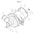
- FIG. 1is a perspective view of an exemplary electric water pump according to the present invention.
- FIG. 2is a cross-sectional view taken along the line A-A in FIG. 1 .
- FIG. 1is a perspective view of an electric water pump according to an exemplary embodiment of the present invention
- FIG. 2is a cross-sectional view taken along the line A-A in FIG. 1 .
- an electric water pump 1includes a pump cover 10 , a body 30 , a driver case 50 , and a driver cover 70 .
- the body 30is engaged to a rear end of the pump cover 10 so as to form a volute chamber 16
- the driver case 50is engaged to a rear end of the body 30 so as to form a rotor chamber 38 and a stator chamber 42
- the driver cover 70is engaged to a rear end of the driver case 50 so as to form a driver chamber 64 .
- an impeller 22is mounted in the volute chamber 16
- a rotor ( 84 , 86 , 88 , and 90 ) fixed to a shaft 82is mounted in the rotor chamber 38
- a stator ( 102 , 104 , 108 , and 109 )is mounted in the stator chamber 42
- a driver 80is mounted in the driver chamber 64 .
- the shaft 82has a central axis x, and the rotor ( 84 , 86 88 , and 90 ) as well as the shaft 82 rotate about the central axis x.
- the stator ( 102 , 104 , 108 , and 109 )is disposed coaxially with the central axis x of the shaft 82 .
- the pump cover 10is provided with an inlet 12 at a front end portion thereof and an outlet 14 at a side portion thereof. Therefore, the coolant flows in the electric water pump 1 through the inlet 12 , and the pressurized coolant in the electric water pump 1 flows out through the outlet 14 .
- a slanted surface 18is formed at a rear end portion of the inlet 12 of the pump cover 10 , and a rear end portion 20 of the pump cover 10 is extended rearward from the slanted surface 18 .
- the rear end portion 20 of the pump cover 10is engaged to a cover mounting portion 44 of the body 30 by fixing means such as a bolt B.
- the slanted surface 18is slanted with reference to the central axis x of the shaft 82 , and an intersecting point P of lines extended from the slanted surface 18 is located on the central axis x of the shaft 82 .
- the volute chamber 16 for pressurizing the coolantis formed in the pump cover 10
- the impeller 22 for pressurizing and discharging the coolant through the outlet 14is mounted in the volute chamber 16 .
- the impeller 22is fixed to a front end portion of the shaft 82 and rotates together with the shaft 82 .
- a bolt hole 29is formed at a middle portion of the impeller 22 and a thread is formed at an interior circumference of the bolt hole 29 . Therefore, an impeller bolt 28 inserted in the bolt hole 29 is threaded to the front end portion of the shaft 82 such that the impeller 22 is fixed to the shaft 82 .
- a washer wmay be interposed between the impeller 22 and the impeller bolt 28 .
- the impeller 22is provided with a confronting surface 26 corresponding to the slanted surface 18 at the front end portion thereof. Therefore, an intersecting point of lines extended from the confronting surface 26 is also positioned on the central axis x of the shaft 82 .
- the coolant having flowed into the water pump 1may be smoothly guided and performance of the water pump 1 may be improved as a consequence of disposing centers of the impeller 22 and the rotor ( 84 , 86 , 88 , and 90 ) that are rotating elements of the water pump 1 and a center of the stator ( 102 , 104 , 108 , and 109 ) that is a fixed element of the water pump 1 on the central axis x.
- the impeller 22is divided into a plurality of regions by a plurality of blades 24 .
- the coolant having flowed into the plurality of regionsis pressurized by rotation of the impeller 22 .
- the body 30has a hollow cylindrical shape that is opened rearward, and is engaged to the rear end of the pump cover 10 .
- the body 30includes a front surface 32 forming the volute chamber 16 with the pump cover 10 , the stator chamber 42 that is formed at an external circumferential portion of the body 30 and in which the stator ( 102 , 104 , 108 , and 109 ) is mounted, and the rotor chamber 38 that is formed at an interior circumferential portion of the stator chamber 42 and in which the rotor ( 84 , 86 , 88 , and 90 ) is mounted.
- the front surface 32 of the body 30is provided with the cover mounting portion 44 , a first stator mounting surface 40 , a first bearing mounting surface 48 , and a penetration hole 34 formed sequentially from an exterior circumference to a center thereof.
- the cover mounting portion 44is engaged to the rear end portion 20 of the pump cover 10 .
- Sealing meanssuch as an O-ring O may be interposed between the cover mounting portion 44 and the rear end portion 20 in order to prevent leakage of the coolant from the volute chamber 16 .
- the first stator mounting surface 40is protruded rearward from the front surface 32 , and defines a boundary between the stator chamber 42 and the rotor chamber 38 .
- the sealing meanssuch as an O-ring O is mounted at the first stator mounting surface 40
- the front end of the stator( 102 , 104 , 108 , and 109 ) is mounted at the first stator mounting surface 40 .
- the first bearing mounting surface 48is protruded rearward from the front surface 32 .
- a first bearing 94is interposed between the first bearing mounting surface 48 and the front end portion of the shaft 82 in order to make the shaft 82 smoothly rotate and to prevent the shaft 82 from being inclined.
- the penetration hole 34is formed at a middle portion of the front surface 32 such that the front end portion of the shaft 82 is protruded to the volute chamber 16 through the penetration hole 34 .
- the impeller 22is fixed to the shaft 82 in the volute chamber 16 . It is exemplarily described in this specification that the impeller 22 is fixed to the shaft 82 by the impeller bolt 28 . However, the impeller 22 may be press-fitted to an exterior circumference of the shaft 82 .
- a connecting hole 36is formed at the front surface 32 between the first stator mounting surface 40 and the first bearing mounting surface 48 . Therefore, the rotor chamber 38 is fluidly connected to the volute chamber 16 . Heat generated at the shaft 82 , the rotor ( 84 , 86 , 88 , and 90 ), and the stator ( 102 , 104 , 108 , and 109 ) by operation of the water pump 1 is cooled by the coolant flowing in and out through the connecting hole 36 . Therefore, durability of the water pump 1 may improve. In addition, floating materials in the coolant are prevented from being accumulated in the rotor chamber 38 .
- the rotor chamber 38is formed at a middle portion in the body 30 .
- the shaft 82 and the rotor ( 84 , 86 , 88 , and 90 )is mounted in the rotor chamber 38 .
- a stepped portion 83is formed at a middle portion of the shaft 82 .
- a hollow shaft 82may be used.
- the rotor ( 84 , 86 , 88 , and 90 )is fixed on the stepped portion 83 of the shaft 82 , and is formed in an unsymmetrical shape. Thrust is exerted on the shaft 82 toward the front surface 32 by the unsymmetrical shape of the rotor ( 84 , 86 , 88 , and 90 ) and a pressure difference between the volute chamber 16 and the rotor chamber 38 . The thrust generated at the shaft 82 pushes the shaft 82 toward the front surface 32 . Thereby, the stepped portion 83 of the shaft 82 may be interfere and collide with the first bearing 94 and the first bearing 94 may be damaged, accordingly.
- a cup 100is mounted between the stepped portion 83 of the shaft 82 and the first bearing 94 .
- Such a cup 100is made of an elastic rubber material, and relieves the thrust of the shaft 82 exerted to the first bearing 94 .
- a thrust ring 98is mounted between the cup 100 and the first bearing 94 in order to reduce the rotation friction between the first bearing 94 and the cup 100 . That is, the cup 100 reduces the thrust of the shaft 82 and the thrust ring 98 reduces the rotation friction of the shaft 82 . It is exemplarily described in this specification that a groove is formed at an exterior circumference of the cup 100 and the thrust ring 98 is mounted in the groove.
- a method for installing the thrust ring 98 to the cup 100is not limited to the exemplary embodiment of the present invention.
- a groovemay be formed at a middle portion of the cup 100 and the thrust ring 98 may be mounted in this groove.
- any thrust ring 98 interposed between the cup 100 and the first bearing 94may be included in the spirit of the present invention.
- the rotor( 84 , 86 , 88 , and 90 ) includes a rotor core 86 , a permanent magnet 88 , a rotor cover 84 , and a rotor case 90 .
- the magnetic rotor core 86has a cylindrical shape and is fixed to the stepped portion 83 of the shaft 82 by press-fitting or welding.
- the rotor core 86is provided with a plurality of recesses (not shown) formed along a length direction thereof at an exterior circumference thereof, and the permanent magnet 88 is insertedly mounted in each recesses.
- the permanent magnet 88is mounted at the exterior circumference of the rotor core 86 .
- a pair of rotor covers 84are mounted at both ends of the rotor core 86 and the permanent magnet 88 .
- the rotor cover 84primarily fixes the rotor core 86 and the permanent magnet 88 , and is made of copper or stainless steel that has high specific gravity.
- the rotor case 90wraps exterior circumferences of the rotor core 86 and the permanent magnet 88 so as to secondarily fix them.
- the rotor case 90is made of a bulk mold compound (BMC) including a potassium family that has a low coefficient of contraction. A method for manufacturing the rotor case 90 will be briefly described.
- the rotor core 86 and the permanent magnet 88are mounted to the rotor cover 84 , and the rotor cover 84 to which the rotor core 86 and the permanent magnet 88 are mounted is inserted in a mold (not shown). After that, the bulk mold compound including the potassium family is melted and high temperature (e.g., 150° C.) and high pressure BMC is flowed into the mold. Then, the BMC is cooled in the mold. As described above, if the rotor case 90 is made of BMC having the low coefficient of contraction, the rotor case 90 can be precisely manufactured. In general, the coefficient of contraction of a resin is 4/1000-5/1000, but the coefficient of contraction of the BMC is about 5/10,000.
- the rotor case 90is manufactured by flowing the high temperature resin into the mold, the rotor case 90 is contracted and does not have a target shape. Therefore, if the rotor case 90 is manufactured by the BMC including the potassium family that has the low coefficient of contraction, contraction of the rotor case 90 by cooling may be reduced and the rotor case 90 may be precisely manufactured. In addition, since BMC including the potassium family has good heat-radiating performance, the rotor can be cooled independently. Therefore, the water pump may be prevented from being heat damaged.
- the permanent magnetis fixed to the exterior circumference of the rotor core with glue.
- gluemay be melted or the permanent magnet may be disengaged from the rotor core.
- the permanent magnet 88 mounted to the rotor core 86is fixed primarily by the rotor cover 84 and secondarily by the rotor case 90 according to an exemplary embodiment of the present invention. Thus, the permanent magnet 88 may not be disengaged from the rotor core 86 .
- the stator chamber 42is formed in the body 30 at a radially outer portion of the rotor chamber 38 .
- the stator( 102 , 104 , 108 , and 109 ) is mounted in the stator chamber 42 .
- the stator( 102 , 104 , 108 , and 109 ) is fixed to the body 30 directly or indirectly, and includes a stator core 102 , an insulator 104 , a coil 108 , and a stator case 109 .
- the stator core 102is formed by stacking a plurality of pieces made of a magnetic material. That is, the plurality of thin pieces are stacked up such that the stator core 102 has a target thickness.
- the insulator 104connects the pieces making up the stator core 102 to each other, and is formed by molding a resin. That is, the stator core 102 formed by stacking the plurality of pieces is inserted in a mold (not shown), and then molten resin is injected into the mold. Thereby, the stator core 102 at which the insulator 104 is mounted is manufactured. At this time, coil mounting recesses 106 are formed at front and rear end portions of the stator core 102 and the insulator 104 .
- the coil 108is coiled at an exterior circumference of the stator core 102 so as to form a magnetic path.
- the stator case 109wraps and seals the stator core 102 , the insulator 104 , and the coil 108 .
- the stator case 109is manufactured by insert molding the BMC including the potassium family.
- stator case 109when the stator case 109 is insert molded, a Hall sensor 112 and a Hall sensor board 110 may also be insert molded. That is, the stator ( 102 , 104 , 108 , and 109 ), the Hall sensor 112 , and the Hall sensor board 110 may be integrally manufactured as one component.
- the Hall sensor 112detects the position of the rotor ( 84 , 86 , 88 , and 90 ).
- a mark (not shown) for representing the position thereofis formed at the rotor ( 84 , 86 , 88 , and 90 ), and the Hall sensor 112 detects the mark in order to detect the position of the rotor ( 84 , 86 , 88 , and 90 ).
- the Hall sensor board 110controls a control signal delivered to the stator 101 according to the position of the rotor ( 84 , 86 , 88 , and 90 ) detected by the Hall sensor. That is, the Hall sensor board 110 makes a strong magnetic field be generated at one part of the stator 101 and a weak magnetic field be generated at the other part of the stator ( 102 , 104 , 108 , and 109 ) according to the position of the rotor ( 84 , 86 , 88 , and 90 ). Thereby, initial mobility of the water pump 1 may be improved.
- a case mounting portion 46is formed at an exterior surface of the rear end of the body 30 .
- the driver case 50is engaged to the rear end of the body 30 , and is formed of a case surface 52 at a front end portion thereof.
- the rotor chamber 38 and the stator chamber 42are formed in the body 30 by engaging the driver case 50 to the rear end portion of the body 30 .
- a body mounting portion 60is formed at an external circumference of the front end portion of the driver case 50 and is engaged to the case mounting portion 46 by fixing means such as a bolt B.
- the case surface 52is provided with an insert portion 54 , a second stator mounting surface 56 , and a second bearing mounting surface 58 formed sequentially from an exterior circumference to a center thereof.
- the insert portion 54is formed at an external circumferential portion of the case surface 52 and is protruded forward.
- the insert portion 54is inserted in and closely contacted to the rear end portion of the body 30 .
- Sealing meanssuch as an O-ring O is interposed between the insert portion 54 and the rear end portion of the body 30 so as to close and seal the stator chamber 42 .
- the second stator mounting surface 56is protruded forward from the case surface 52 so as to define the boundary between the stator chamber 42 and the rotor chamber 38 .
- the rear end of the stator ( 102 , 104 , 108 , and 109 )is mounted at the second stator mounting surface 56 with a sealing means such as an O-ring O being interposed.
- the stator chamber 42is not fluidly connected to the rotor chamber 38 by the O-ring O interposed between the first stator mounting surface 40 and the front end of the stator ( 102 , 104 , 108 , and 109 ) and the O-ring O interposed between the second stator mounting surface 56 and the rear end of the stator ( 102 , 104 , 108 , and 109 ). Therefore, the coolant having flowed in the rotor chamber 38 does not flow to the stator chamber 42 .
- the second bearing mounting surface 58is protruded forwardly from the case surface 52 .
- a second bearing 96is interposed between the second bearing mounting surface 58 and the rear end portion of the shaft 82 so as to make the shaft 82 smoothly rotate and to prevent the shaft 82 from being inclined.
- the rear end of the driver case 50is open.
- the driver chamber 64is formed between the driver case 50 and the driver cover 70 by engaging the driver cover 70 of a disk shape to the rear end of the driver 50 by fixing means such as a bolt B.
- a protruding portion 72is protruded forward from an exterior circumference of the driver cover 70 , and this protruding portion 72 is inserted in and closely contacted to an exterior circumference 62 of the rear end of the driver case 50 .
- Sealing meanssuch as an O-ring O is interposed between the protruding portion 72 and the exterior circumference 62 so as to prevent foreign substances such as dust from entering the driver chamber 64 .
- the driver 80 controlling operation of the water pump 1is mounted in the driver chamber 64 .
- the driver 80includes microprocessors and a printed circuit board (PCB).
- the driver 80is electrically connected to a controller (not shown) disposed at an exterior of the electric water pump 1 through a connector 74 and receives a control signal of the controller.
- the driver 80is electrically connected to the Hall sensor board 110 so as to transmit the control signal received from the controller to the Hall sensor board 110 .
- the driver chamber 64is isolated from the rotor chamber 38 by the case surface 52 . Therefore, the coolant in the rotor chamber 38 does not flow into the driver chamber 64 .
- initial mobility of the electric water pumpmay improve.
- the rotorsince the coolant flows in a rotor chamber where the rotor is mounted, the rotor may be cooled and foreign materials in the rotor chamber may be removed.
Landscapes
- Engineering & Computer Science (AREA)
- Mechanical Engineering (AREA)
- General Engineering & Computer Science (AREA)
- Power Engineering (AREA)
- Microelectronics & Electronic Packaging (AREA)
- Manufacturing & Machinery (AREA)
- Chemical & Material Sciences (AREA)
- Combustion & Propulsion (AREA)
- Structures Of Non-Positive Displacement Pumps (AREA)
Abstract
Description
Claims (16)
Applications Claiming Priority (2)
| Application Number | Priority Date | Filing Date | Title |
|---|---|---|---|
| KR10-2009-0112235 | 2009-11-19 | ||
| KR1020090112235AKR101134968B1 (en) | 2009-11-19 | 2009-11-19 | Electric water pump |
Publications (2)
| Publication Number | Publication Date |
|---|---|
| US20110116947A1 US20110116947A1 (en) | 2011-05-19 |
| US8747082B2true US8747082B2 (en) | 2014-06-10 |
Family
ID=43902215
Family Applications (1)
| Application Number | Title | Priority Date | Filing Date |
|---|---|---|---|
| US12/847,950Active2032-02-22US8747082B2 (en) | 2009-11-19 | 2010-07-30 | Electric water pump |
Country Status (5)
| Country | Link |
|---|---|
| US (1) | US8747082B2 (en) |
| JP (1) | JP2011106439A (en) |
| KR (1) | KR101134968B1 (en) |
| CN (1) | CN102072168B (en) |
| DE (1) | DE102010036935A1 (en) |
Cited By (6)
| Publication number | Priority date | Publication date | Assignee | Title |
|---|---|---|---|---|
| US20150139828A1 (en)* | 2013-11-19 | 2015-05-21 | Charles Wayne Zimmerman | Two piece impeller centrifugal pump |
| EP3001037A1 (en) | 2014-09-25 | 2016-03-30 | Magna Powertrain Inc. | Electric fluid pump with improved rotor unit and method of construction thereof |
| US9587643B1 (en)* | 2007-03-14 | 2017-03-07 | Don Mason | Drive shaft for marine water pump |
| US11043871B2 (en) | 2018-02-08 | 2021-06-22 | Sunonwealth Electric Machine Industry Co., Ltd. | Stator of a waterproof motor and method for manufacturing the same |
| US20220178375A1 (en)* | 2020-12-04 | 2022-06-09 | Youngshin Precision Co., LTD | Electric water pump |
| US12297837B2 (en) | 2021-09-09 | 2025-05-13 | Techtronic Cordless Gp | Submersible pump |
Families Citing this family (15)
| Publication number | Priority date | Publication date | Assignee | Title |
|---|---|---|---|---|
| KR101305671B1 (en) | 2011-11-29 | 2013-09-09 | 현대자동차주식회사 | Electric water pump |
| CN102518590A (en)* | 2011-12-23 | 2012-06-27 | 上海电机学院 | Transverse magnetic field magnetic pump |
| KR101454083B1 (en)* | 2012-12-28 | 2014-10-21 | 삼성전기주식회사 | Electric blower |
| KR101911782B1 (en)* | 2013-01-25 | 2018-10-26 | 한온시스템 주식회사 | Air blower for fuel cell vehicle |
| DE102013215048A1 (en)* | 2013-07-31 | 2015-02-05 | Robert Bosch Gmbh | Rotor for an electric motor and method of manufacturing the rotor |
| CN103438006B (en)* | 2013-08-20 | 2016-04-06 | 山东科技大学 | Miniature hot-water recycle pump |
| FR3022599B1 (en)* | 2014-06-20 | 2017-03-10 | Wilo Salmson France | CYLINDRICAL AND PARTIALLY COATED METALLIC TREE |
| EP3332125B1 (en)* | 2015-08-06 | 2024-11-06 | OneSubsea IP UK Limited | Fluid processing machines and fluid production systems |
| CN105221441A (en)* | 2015-09-18 | 2016-01-06 | 河南省西峡汽车水泵股份有限公司 | The motorcar electric water pump of a kind of low energy consumption long-life |
| DE102017203833A1 (en) | 2017-03-08 | 2018-09-13 | Mahle International Gmbh | liquid pump |
| CN108757578A (en)* | 2018-04-24 | 2018-11-06 | 珠海万伏科技有限公司 | Heat radiating type electronic water pump |
| US20200040893A1 (en)* | 2018-08-03 | 2020-02-06 | Lg Electronics Inc. | Motor-operated compressor |
| DE102019201367A1 (en)* | 2019-02-04 | 2020-08-06 | Brose Fahrzeugteile SE & Co. Kommanditgesellschaft, Würzburg | Drive of an auxiliary unit |
| CN110418549B (en)* | 2019-06-18 | 2021-01-29 | 华为技术有限公司 | Heat dissipation assembly and electronic equipment |
| US20240178723A1 (en)* | 2021-03-23 | 2024-05-30 | Lilium Eaircraft Gmbh | Cooling for an electric drive of an aircraft |
Citations (90)
| Publication number | Priority date | Publication date | Assignee | Title |
|---|---|---|---|---|
| US2713311A (en) | 1949-12-06 | 1955-07-19 | Howard T White | Motor driven pump |
| US2718193A (en) | 1952-03-22 | 1955-09-20 | Mcgraw Electric Co | Motor-pump unit |
| US2906208A (en)* | 1955-07-14 | 1959-09-29 | Fostoria Corp | Motor driven pumps |
| US2925041A (en) | 1955-01-28 | 1960-02-16 | Sigmund Miroslav | Pump and driving motor unit |
| US3053189A (en)* | 1959-12-22 | 1962-09-11 | Fostoria Corp | Motor driven pumps |
| US3135211A (en)* | 1960-09-28 | 1964-06-02 | Integral Motor Pump Corp | Motor and pump assembly |
| US3138105A (en)* | 1961-02-08 | 1964-06-23 | Fostoria Corp | Motor driven pumps |
| US3220349A (en)* | 1964-09-09 | 1965-11-30 | Crane Co | Motor driven pump |
| US3223043A (en) | 1963-09-24 | 1965-12-14 | Gen Dynamics Corp | Axial air gap motor adapted for canned pump |
| US3967915A (en)* | 1975-01-27 | 1976-07-06 | Litzenberg David P | Centrifugal pump |
| US4080112A (en) | 1976-02-03 | 1978-03-21 | March Manufacturing Company | Magnetically-coupled pump |
| US4465437A (en) | 1981-02-14 | 1984-08-14 | Grundfos A/S | Pump comprising a canned motor |
| US4886430A (en) | 1988-07-18 | 1989-12-12 | Westinghouse Electric Corp. | Canned pump having a high inertia flywheel |
| US4890988A (en) | 1986-11-20 | 1990-01-02 | Heyko Reinecker | Canned motor pump |
| JPH0284032A (en) | 1988-04-25 | 1990-03-26 | Matsushita Electric Works Ltd | Permanent magnet rotor |
| US5009578A (en)* | 1987-10-27 | 1991-04-23 | Crane Co. | Motor driven pumps |
| US5044897A (en) | 1989-07-10 | 1991-09-03 | Regents Of The University Of Minnesota | Radial drive for implantable centrifugal cardiac assist pump |
| US5129795A (en)* | 1991-05-31 | 1992-07-14 | Powerdyne Corporation | Motor driven pump |
| US5156535A (en) | 1990-10-31 | 1992-10-20 | Itt Corporation | High speed whirlpool pump |
| US5160246A (en)* | 1989-11-08 | 1992-11-03 | Sanwa Koki Co., Ltd. | Magnetically driven cyntrifical pump |
| US5184945A (en) | 1991-12-27 | 1993-02-09 | Assoma, Inc. | Bushing structure for using in magnetically driving centrifugal pumps |
| US5297940A (en) | 1992-12-28 | 1994-03-29 | Ingersoll-Dresser Pump Company | Sealless pump corrosion detector |
| US5302091A (en) | 1992-03-24 | 1994-04-12 | Sanwa Hydrotech Corp. | Magnetically driven centrifugal pump |
| US5407331A (en) | 1992-01-14 | 1995-04-18 | Mitsubishi Jukogyo Kabushiki Kaisha | Motor-driven pump |
| US5464333A (en) | 1993-06-24 | 1995-11-07 | Iwaki Co., Ltd. | Magnet pump with rear thrust bearing member |
| US5580216A (en) | 1993-12-22 | 1996-12-03 | Stefan Munsch | Magnetic pump |
| JPH09324787A (en) | 1996-06-04 | 1997-12-16 | Tsurumi Mfg Co Ltd | Submersible electric pump |
| US5830258A (en) | 1995-06-13 | 1998-11-03 | Matsushita Electric Industrial Co., Ltd. | Method of recovering resources in resin-molded electrical rotating device |
| KR19980062328U (en) | 1997-04-01 | 1998-11-16 | 윤종용 | Rotor for electric motor |
| US5890880A (en) | 1996-08-09 | 1999-04-06 | Lustwerk; Ferdinand | Sealed motor driven centrifugal fluid pump |
| US5915931A (en) | 1997-11-13 | 1999-06-29 | The Gorman-Rupp Company | Magnetic drive unit having molded plastic magnetic driver |
| US5924851A (en) | 1995-12-08 | 1999-07-20 | Aisan Kogyo Kabushiki Kaisha | Magnetically coupled pump having a back-up radical sliding surface on the shaft |
| US5997261A (en)* | 1997-10-31 | 1999-12-07 | Siemens Canada Limited | Pump motor having fluid cooling system |
| US6012909A (en)* | 1997-09-24 | 2000-01-11 | Ingersoll-Dresser Pump Co. | Centrifugal pump with an axial-field integral motor cooled by working fluid |
| US6018208A (en) | 1999-01-26 | 2000-01-25 | Nimbus, Inc. | Articulated motor stator assembly for a pump |
| US6027318A (en) | 1995-09-26 | 2000-02-22 | Aisin Seiki Kabushiki Kaisha | Magnetically driven pump |
| US6036456A (en) | 1997-09-16 | 2000-03-14 | Pierburg Ag | Electrical air pump adapted for being periodically turned on and off and reversed in pumping direction |
| CN1250554A (en) | 1997-02-21 | 2000-04-12 | 埃莫森电器公司 | Rotor assembly for a rotating machine |
| US6082974A (en)* | 1996-03-18 | 2000-07-04 | Mitsuba Corporation | Liquid-cooled compact motor pump |
| US6102674A (en) | 1997-09-19 | 2000-08-15 | Tcg Unitech Aktiengesellschaft | Electrically operated coolant pump |
| JP2000278924A (en) | 1999-03-19 | 2000-10-06 | Nippon Densan Corp | Rotating machine |
| JP2001136700A (en) | 1999-11-02 | 2001-05-18 | Mitsubishi Electric Corp | Stator and stator manufacturing method |
| CN1307741A (en) | 1997-03-28 | 2001-08-08 | 松下电器产业株式会社 | Member to form motor stator |
| US6302661B1 (en) | 1996-05-03 | 2001-10-16 | Pratap S. Khanwilkar | Electromagnetically suspended and rotated centrifugal pumping apparatus and method |
| US6350109B1 (en)* | 1997-09-12 | 2002-02-26 | Societe De Mecanique Magnetique | Rotary pump with immersed rotor |
| KR20020064360A (en) | 2000-10-25 | 2002-08-07 | 로베르트 보쉬 게엠베하 | Pump driven by an electromotor and method for producing a pump of this type |
| US6447269B1 (en)* | 2000-12-15 | 2002-09-10 | Sota Corporation | Potable water pump |
| US6464471B1 (en) | 1998-09-08 | 2002-10-15 | Sta-Rite Industries, Inc. | High-efficiency motor/pump system for jetted bath/spas |
| US20020150486A1 (en) | 1997-08-06 | 2002-10-17 | Shurflo Pump Manufacturing Co. | Dynamo electric machines and stators for use in same |
| US6477269B1 (en) | 1999-04-20 | 2002-11-05 | Microsoft Corporation | Method and system for searching for images based on color and shape of a selected image |
| JP2003003984A (en) | 2001-06-21 | 2003-01-08 | Sanyo Seiki Kogyo Kk | Canned pump |
| CN1434557A (en) | 2001-12-21 | 2003-08-06 | 德昌电机股份有限公司 | Brushless dc motor |
| US20040037719A1 (en)* | 2002-01-30 | 2004-02-26 | Calsonic Kansei Corporation | Canned pump |
| CN1484883A (en) | 2000-12-07 | 2004-03-24 | ���µ�����ҵ��ʽ���� | Method for manufacturing motor stator and the stator |
| US6722854B2 (en) | 2001-01-24 | 2004-04-20 | Sundyne Corporation | Canned pump with ultrasonic bubble detector |
| JP2004129369A (en) | 2002-10-02 | 2004-04-22 | Mitsubishi Electric Corp | Rotor of rotating electric machine and method of manufacturing the same |
| US20040115077A1 (en) | 2002-12-10 | 2004-06-17 | Denso Corporation | Fuel pump to be installed inside fuel tank |
| JP2004183595A (en) | 2002-12-05 | 2004-07-02 | Calsonic Kansei Corp | Electric brushless water pump |
| JP2004282989A (en) | 2003-02-26 | 2004-10-07 | Fujitsu General Ltd | Axial gap type motor |
| US6817845B2 (en)* | 2002-04-19 | 2004-11-16 | Envirotech Pumpsystems, Inc. | Centrifugal pump with switched reluctance motor drive |
| US6844640B2 (en)* | 2001-08-06 | 2005-01-18 | Hitachi, Ltd. | Electrical equipment for mounting on vehicles, electrical machines, and manufacturing methods of the same |
| US20050025642A1 (en)* | 2003-07-30 | 2005-02-03 | Aisin Seiki Kabushiki Kaisha | Pump device |
| US6884043B2 (en)* | 2002-02-28 | 2005-04-26 | Standex International Corp. | Fluid circulation path for motor pump |
| JP2005287149A (en) | 2004-03-29 | 2005-10-13 | Toyota Motor Corp | Temperature control device and temperature control method |
| US20050254971A1 (en) | 2002-04-08 | 2005-11-17 | Ikuo Ohya | Electromagnetic vibrating type diaphragm pump |
| US20060057002A1 (en)* | 2004-09-15 | 2006-03-16 | Aisan Kogyo Kabushiki Kaisha | Electronic control unit and electric pump |
| US20060057006A1 (en)* | 2004-09-14 | 2006-03-16 | Williams David J | Pump assembly |
| US20060057005A1 (en) | 2004-09-14 | 2006-03-16 | David John Williams | Pump assembly |
| US7033146B2 (en) | 2003-01-08 | 2006-04-25 | Assoma Inc. | Sealed magnetic drive sealless pump |
| CN1773122A (en) | 2004-11-08 | 2006-05-17 | 浙江工业大学 | Permanent magnet wet pump |
| US7074019B2 (en)* | 2001-10-24 | 2006-07-11 | Pierburg Gmbh | Rotor protector for wet-type rotor pump |
| US20060245956A1 (en)* | 2003-07-24 | 2006-11-02 | Lacroix Michael C | Electric fluid pump |
| US20070018521A1 (en)* | 2005-07-25 | 2007-01-25 | Aisin Seiki Kabushiki Kaisha | Electric pump |
| US20070086905A1 (en) | 2005-10-18 | 2007-04-19 | Denso Corporation | Brushless motor and fluid pump having the same |
| KR20070053123A (en) | 2005-11-18 | 2007-05-23 | 아스콜 홀딩 에스.알.엘. | Method for manufacturing permanent magnet rotor for synchronous motors used in pumps for industrial and domestic washing machines and the rotor accordingly |
| JP2007205246A (en) | 2006-02-01 | 2007-08-16 | Toyota Motor Corp | Water pump and hybrid vehicle |
| US20070243086A1 (en)* | 2006-04-18 | 2007-10-18 | Matsushita Electric Works, Ltd. | Pump and liquid supplying apparatus |
| US7300263B2 (en) | 2004-04-23 | 2007-11-27 | Mitsubishi Heavy Industries, Ltd. | Pump |
| JP2007318987A (en) | 2006-04-28 | 2007-12-06 | Nippon Densan Corp | Motor and pump comprising magnetic sensor, method of manufacturing stator, and manufacturing method of motor and pump |
| CN200993106Y (en) | 2006-10-31 | 2007-12-19 | 潘隐萱 | Pipeline circulating pump |
| JP2008008222A (en) | 2006-06-29 | 2008-01-17 | Nidec Sankyo Corp | Pump device |
| US20080019850A1 (en)* | 2006-07-21 | 2008-01-24 | Hitachi, Ltd. | Electric Pump |
| US20080100165A1 (en) | 2006-10-27 | 2008-05-01 | Glacier Bay, Inc. | Integrated permanent magnet motor and blower |
| US20080112824A1 (en)* | 2006-11-09 | 2008-05-15 | Nidec Shibaura Corporation | Pump |
| JP2008175090A (en) | 2007-01-16 | 2008-07-31 | Mitsuba Corp | Motor-driven pump |
| WO2009038302A2 (en) | 2007-09-18 | 2009-03-26 | Amotech Co., Ltd. | Ipm motor and vacuum inhaling apparatus using the same |
| WO2009056271A1 (en) | 2007-10-29 | 2009-05-07 | Grundfos Management A/S | Magnetic drive arrangement |
| KR100908396B1 (en) | 2007-04-23 | 2009-07-20 | 주식회사 아모텍 | XLD motor stator, XLD motor with double rotor / single stator structure and automotive cooling device using same |
| JP2009177985A (en) | 2008-01-25 | 2009-08-06 | Panasonic Electric Works Co Ltd | Motor and motor-integrated pump equipped with the motor |
| CN201332347Y (en) | 2008-11-27 | 2009-10-21 | 郑云峰 | Brushless motor water pump |
Family Cites Families (3)
| Publication number | Priority date | Publication date | Assignee | Title |
|---|---|---|---|---|
| JP4716505B2 (en)* | 2006-04-10 | 2011-07-06 | 日本電産サンキョー株式会社 | Motor and electric device using the same |
| JP4864611B2 (en) | 2006-09-04 | 2012-02-01 | ケーピーエス工業株式会社 | Cand pump |
| KR20090112235A (en) | 2008-04-24 | 2009-10-28 | 박민구 | Human chromosome microdeletion analysis chip and idiopathic infertility screening test |
- 2009
- 2009-11-19KRKR1020090112235Apatent/KR101134968B1/enactiveActive
- 2010
- 2010-06-15JPJP2010136365Apatent/JP2011106439A/enactivePending
- 2010-07-30USUS12/847,950patent/US8747082B2/enactiveActive
- 2010-08-10DEDE102010036935Apatent/DE102010036935A1/ennot_activeCeased
- 2010-08-11CNCN201010250644.8Apatent/CN102072168B/enactiveActive
Patent Citations (97)
| Publication number | Priority date | Publication date | Assignee | Title |
|---|---|---|---|---|
| US2713311A (en) | 1949-12-06 | 1955-07-19 | Howard T White | Motor driven pump |
| US2718193A (en) | 1952-03-22 | 1955-09-20 | Mcgraw Electric Co | Motor-pump unit |
| US2925041A (en) | 1955-01-28 | 1960-02-16 | Sigmund Miroslav | Pump and driving motor unit |
| US2906208A (en)* | 1955-07-14 | 1959-09-29 | Fostoria Corp | Motor driven pumps |
| US3053189A (en)* | 1959-12-22 | 1962-09-11 | Fostoria Corp | Motor driven pumps |
| US3135211A (en)* | 1960-09-28 | 1964-06-02 | Integral Motor Pump Corp | Motor and pump assembly |
| US3138105A (en)* | 1961-02-08 | 1964-06-23 | Fostoria Corp | Motor driven pumps |
| US3223043A (en) | 1963-09-24 | 1965-12-14 | Gen Dynamics Corp | Axial air gap motor adapted for canned pump |
| US3220349A (en)* | 1964-09-09 | 1965-11-30 | Crane Co | Motor driven pump |
| US3967915A (en)* | 1975-01-27 | 1976-07-06 | Litzenberg David P | Centrifugal pump |
| US4080112A (en) | 1976-02-03 | 1978-03-21 | March Manufacturing Company | Magnetically-coupled pump |
| US4465437A (en) | 1981-02-14 | 1984-08-14 | Grundfos A/S | Pump comprising a canned motor |
| US4890988A (en) | 1986-11-20 | 1990-01-02 | Heyko Reinecker | Canned motor pump |
| US5009578A (en)* | 1987-10-27 | 1991-04-23 | Crane Co. | Motor driven pumps |
| JPH0284032A (en) | 1988-04-25 | 1990-03-26 | Matsushita Electric Works Ltd | Permanent magnet rotor |
| US4886430A (en) | 1988-07-18 | 1989-12-12 | Westinghouse Electric Corp. | Canned pump having a high inertia flywheel |
| US5044897A (en) | 1989-07-10 | 1991-09-03 | Regents Of The University Of Minnesota | Radial drive for implantable centrifugal cardiac assist pump |
| US5160246A (en)* | 1989-11-08 | 1992-11-03 | Sanwa Koki Co., Ltd. | Magnetically driven cyntrifical pump |
| US5156535A (en) | 1990-10-31 | 1992-10-20 | Itt Corporation | High speed whirlpool pump |
| US5129795A (en)* | 1991-05-31 | 1992-07-14 | Powerdyne Corporation | Motor driven pump |
| US5184945A (en) | 1991-12-27 | 1993-02-09 | Assoma, Inc. | Bushing structure for using in magnetically driving centrifugal pumps |
| US5407331A (en) | 1992-01-14 | 1995-04-18 | Mitsubishi Jukogyo Kabushiki Kaisha | Motor-driven pump |
| US5302091A (en) | 1992-03-24 | 1994-04-12 | Sanwa Hydrotech Corp. | Magnetically driven centrifugal pump |
| US5297940A (en) | 1992-12-28 | 1994-03-29 | Ingersoll-Dresser Pump Company | Sealless pump corrosion detector |
| US5464333A (en) | 1993-06-24 | 1995-11-07 | Iwaki Co., Ltd. | Magnet pump with rear thrust bearing member |
| US5580216A (en) | 1993-12-22 | 1996-12-03 | Stefan Munsch | Magnetic pump |
| US5830258A (en) | 1995-06-13 | 1998-11-03 | Matsushita Electric Industrial Co., Ltd. | Method of recovering resources in resin-molded electrical rotating device |
| US6027318A (en) | 1995-09-26 | 2000-02-22 | Aisin Seiki Kabushiki Kaisha | Magnetically driven pump |
| US5924851A (en) | 1995-12-08 | 1999-07-20 | Aisan Kogyo Kabushiki Kaisha | Magnetically coupled pump having a back-up radical sliding surface on the shaft |
| US6082974A (en)* | 1996-03-18 | 2000-07-04 | Mitsuba Corporation | Liquid-cooled compact motor pump |
| US6302661B1 (en) | 1996-05-03 | 2001-10-16 | Pratap S. Khanwilkar | Electromagnetically suspended and rotated centrifugal pumping apparatus and method |
| JPH09324787A (en) | 1996-06-04 | 1997-12-16 | Tsurumi Mfg Co Ltd | Submersible electric pump |
| US5890880A (en) | 1996-08-09 | 1999-04-06 | Lustwerk; Ferdinand | Sealed motor driven centrifugal fluid pump |
| US6078121A (en) | 1997-02-21 | 2000-06-20 | Emerson Electric Co. | Rotor assembly for a rotating machine |
| CN1250554A (en) | 1997-02-21 | 2000-04-12 | 埃莫森电器公司 | Rotor assembly for a rotating machine |
| CN1307741A (en) | 1997-03-28 | 2001-08-08 | 松下电器产业株式会社 | Member to form motor stator |
| KR19980062328U (en) | 1997-04-01 | 1998-11-16 | 윤종용 | Rotor for electric motor |
| US20020150486A1 (en) | 1997-08-06 | 2002-10-17 | Shurflo Pump Manufacturing Co. | Dynamo electric machines and stators for use in same |
| US6350109B1 (en)* | 1997-09-12 | 2002-02-26 | Societe De Mecanique Magnetique | Rotary pump with immersed rotor |
| US6036456A (en) | 1997-09-16 | 2000-03-14 | Pierburg Ag | Electrical air pump adapted for being periodically turned on and off and reversed in pumping direction |
| US6102674A (en) | 1997-09-19 | 2000-08-15 | Tcg Unitech Aktiengesellschaft | Electrically operated coolant pump |
| US6012909A (en)* | 1997-09-24 | 2000-01-11 | Ingersoll-Dresser Pump Co. | Centrifugal pump with an axial-field integral motor cooled by working fluid |
| US5997261A (en)* | 1997-10-31 | 1999-12-07 | Siemens Canada Limited | Pump motor having fluid cooling system |
| US5915931A (en) | 1997-11-13 | 1999-06-29 | The Gorman-Rupp Company | Magnetic drive unit having molded plastic magnetic driver |
| US6464471B1 (en) | 1998-09-08 | 2002-10-15 | Sta-Rite Industries, Inc. | High-efficiency motor/pump system for jetted bath/spas |
| US6018208A (en) | 1999-01-26 | 2000-01-25 | Nimbus, Inc. | Articulated motor stator assembly for a pump |
| JP2000278924A (en) | 1999-03-19 | 2000-10-06 | Nippon Densan Corp | Rotating machine |
| US6477269B1 (en) | 1999-04-20 | 2002-11-05 | Microsoft Corporation | Method and system for searching for images based on color and shape of a selected image |
| JP2001136700A (en) | 1999-11-02 | 2001-05-18 | Mitsubishi Electric Corp | Stator and stator manufacturing method |
| KR20020064360A (en) | 2000-10-25 | 2002-08-07 | 로베르트 보쉬 게엠베하 | Pump driven by an electromotor and method for producing a pump of this type |
| JP2004512462A (en) | 2000-10-25 | 2004-04-22 | ローベルト ボツシユ ゲゼルシヤフト ミツト ベシユレンクテル ハフツング | Pump driven by an electric motor and method for manufacturing such a pump |
| US20040062664A1 (en)* | 2000-10-25 | 2004-04-01 | Thomas Weigold | Pump driven by an electromotor and method for producing a pump of this type |
| CN1484883A (en) | 2000-12-07 | 2004-03-24 | ���µ�����ҵ��ʽ���� | Method for manufacturing motor stator and the stator |
| US6447269B1 (en)* | 2000-12-15 | 2002-09-10 | Sota Corporation | Potable water pump |
| US6722854B2 (en) | 2001-01-24 | 2004-04-20 | Sundyne Corporation | Canned pump with ultrasonic bubble detector |
| JP2003003984A (en) | 2001-06-21 | 2003-01-08 | Sanyo Seiki Kogyo Kk | Canned pump |
| US6844640B2 (en)* | 2001-08-06 | 2005-01-18 | Hitachi, Ltd. | Electrical equipment for mounting on vehicles, electrical machines, and manufacturing methods of the same |
| US7074019B2 (en)* | 2001-10-24 | 2006-07-11 | Pierburg Gmbh | Rotor protector for wet-type rotor pump |
| CN1434557A (en) | 2001-12-21 | 2003-08-06 | 德昌电机股份有限公司 | Brushless dc motor |
| US6896494B2 (en)* | 2002-01-30 | 2005-05-24 | Calsonic Kansei Corporation | Canned pump |
| US20040037719A1 (en)* | 2002-01-30 | 2004-02-26 | Calsonic Kansei Corporation | Canned pump |
| US6884043B2 (en)* | 2002-02-28 | 2005-04-26 | Standex International Corp. | Fluid circulation path for motor pump |
| US20050254971A1 (en) | 2002-04-08 | 2005-11-17 | Ikuo Ohya | Electromagnetic vibrating type diaphragm pump |
| US6817845B2 (en)* | 2002-04-19 | 2004-11-16 | Envirotech Pumpsystems, Inc. | Centrifugal pump with switched reluctance motor drive |
| JP2004129369A (en) | 2002-10-02 | 2004-04-22 | Mitsubishi Electric Corp | Rotor of rotating electric machine and method of manufacturing the same |
| JP2004183595A (en) | 2002-12-05 | 2004-07-02 | Calsonic Kansei Corp | Electric brushless water pump |
| US20040115077A1 (en) | 2002-12-10 | 2004-06-17 | Denso Corporation | Fuel pump to be installed inside fuel tank |
| US7033146B2 (en) | 2003-01-08 | 2006-04-25 | Assoma Inc. | Sealed magnetic drive sealless pump |
| JP2004282989A (en) | 2003-02-26 | 2004-10-07 | Fujitsu General Ltd | Axial gap type motor |
| US7221073B2 (en) | 2003-02-26 | 2007-05-22 | Fujitsu General Limited | Axial gap electronic motor |
| US20060245956A1 (en)* | 2003-07-24 | 2006-11-02 | Lacroix Michael C | Electric fluid pump |
| US20050025642A1 (en)* | 2003-07-30 | 2005-02-03 | Aisin Seiki Kabushiki Kaisha | Pump device |
| JP2005287149A (en) | 2004-03-29 | 2005-10-13 | Toyota Motor Corp | Temperature control device and temperature control method |
| US7300263B2 (en) | 2004-04-23 | 2007-11-27 | Mitsubishi Heavy Industries, Ltd. | Pump |
| US20060057006A1 (en)* | 2004-09-14 | 2006-03-16 | Williams David J | Pump assembly |
| US20060057005A1 (en) | 2004-09-14 | 2006-03-16 | David John Williams | Pump assembly |
| US20060057002A1 (en)* | 2004-09-15 | 2006-03-16 | Aisan Kogyo Kabushiki Kaisha | Electronic control unit and electric pump |
| CN1773122A (en) | 2004-11-08 | 2006-05-17 | 浙江工业大学 | Permanent magnet wet pump |
| US20070018521A1 (en)* | 2005-07-25 | 2007-01-25 | Aisin Seiki Kabushiki Kaisha | Electric pump |
| US20070086905A1 (en) | 2005-10-18 | 2007-04-19 | Denso Corporation | Brushless motor and fluid pump having the same |
| CN1952379A (en) | 2005-10-18 | 2007-04-25 | 株式会社电装 | Brushless motor and fluid pump having same |
| KR20070053123A (en) | 2005-11-18 | 2007-05-23 | 아스콜 홀딩 에스.알.엘. | Method for manufacturing permanent magnet rotor for synchronous motors used in pumps for industrial and domestic washing machines and the rotor accordingly |
| US20070114867A1 (en) | 2005-11-18 | 2007-05-24 | Askoll Holding S.R.L. | Method for realising a permanent-magnet rotor for a synchronous motor particularly for a washing machine pump for industrial and domestic use and the like, and relative rotor |
| JP2007205246A (en) | 2006-02-01 | 2007-08-16 | Toyota Motor Corp | Water pump and hybrid vehicle |
| US20070243086A1 (en)* | 2006-04-18 | 2007-10-18 | Matsushita Electric Works, Ltd. | Pump and liquid supplying apparatus |
| JP2007318987A (en) | 2006-04-28 | 2007-12-06 | Nippon Densan Corp | Motor and pump comprising magnetic sensor, method of manufacturing stator, and manufacturing method of motor and pump |
| JP2008008222A (en) | 2006-06-29 | 2008-01-17 | Nidec Sankyo Corp | Pump device |
| US20080019850A1 (en)* | 2006-07-21 | 2008-01-24 | Hitachi, Ltd. | Electric Pump |
| US20080100165A1 (en) | 2006-10-27 | 2008-05-01 | Glacier Bay, Inc. | Integrated permanent magnet motor and blower |
| CN200993106Y (en) | 2006-10-31 | 2007-12-19 | 潘隐萱 | Pipeline circulating pump |
| US20080112824A1 (en)* | 2006-11-09 | 2008-05-15 | Nidec Shibaura Corporation | Pump |
| JP2008175090A (en) | 2007-01-16 | 2008-07-31 | Mitsuba Corp | Motor-driven pump |
| KR100908396B1 (en) | 2007-04-23 | 2009-07-20 | 주식회사 아모텍 | XLD motor stator, XLD motor with double rotor / single stator structure and automotive cooling device using same |
| WO2009038302A2 (en) | 2007-09-18 | 2009-03-26 | Amotech Co., Ltd. | Ipm motor and vacuum inhaling apparatus using the same |
| WO2009056271A1 (en) | 2007-10-29 | 2009-05-07 | Grundfos Management A/S | Magnetic drive arrangement |
| JP2009177985A (en) | 2008-01-25 | 2009-08-06 | Panasonic Electric Works Co Ltd | Motor and motor-integrated pump equipped with the motor |
| CN201332347Y (en) | 2008-11-27 | 2009-10-21 | 郑云峰 | Brushless motor water pump |
Cited By (9)
| Publication number | Priority date | Publication date | Assignee | Title |
|---|---|---|---|---|
| US9587643B1 (en)* | 2007-03-14 | 2017-03-07 | Don Mason | Drive shaft for marine water pump |
| US20150139828A1 (en)* | 2013-11-19 | 2015-05-21 | Charles Wayne Zimmerman | Two piece impeller centrifugal pump |
| US9739284B2 (en)* | 2013-11-19 | 2017-08-22 | Charles Wayne Zimmerman | Two piece impeller centrifugal pump |
| EP3001037A1 (en) | 2014-09-25 | 2016-03-30 | Magna Powertrain Inc. | Electric fluid pump with improved rotor unit and method of construction thereof |
| US10291091B2 (en) | 2014-09-25 | 2019-05-14 | Magna Powertrain Fpc Limited Partnership | Electric fluid pump with improved rotor unit, rotor unit therefor and methods of construction thereof |
| US11043871B2 (en) | 2018-02-08 | 2021-06-22 | Sunonwealth Electric Machine Industry Co., Ltd. | Stator of a waterproof motor and method for manufacturing the same |
| US11387703B2 (en) | 2018-02-08 | 2022-07-12 | Sunonwealth Electric Machine Industry Co., Ltd. | Stator of a waterproof motor and method for manufacturing the same |
| US20220178375A1 (en)* | 2020-12-04 | 2022-06-09 | Youngshin Precision Co., LTD | Electric water pump |
| US12297837B2 (en) | 2021-09-09 | 2025-05-13 | Techtronic Cordless Gp | Submersible pump |
Also Published As
| Publication number | Publication date |
|---|---|
| JP2011106439A (en) | 2011-06-02 |
| CN102072168A (en) | 2011-05-25 |
| KR20110055280A (en) | 2011-05-25 |
| US20110116947A1 (en) | 2011-05-19 |
| DE102010036935A1 (en) | 2011-05-26 |
| CN102072168B (en) | 2015-12-09 |
| KR101134968B1 (en) | 2012-04-09 |
Similar Documents
| Publication | Publication Date | Title |
|---|---|---|
| US8747082B2 (en) | Electric water pump | |
| US8562314B2 (en) | Electric water pump | |
| US8304939B2 (en) | Electric water pump with molded circuit board and hall sensor | |
| US8839503B2 (en) | Method for manufacturing stator for electric water pump | |
| US20110116953A1 (en) | Electric Water Pump | |
| US8961154B2 (en) | Electric water pump | |
| US20110033320A1 (en) | Pump rotor for a canned motor pump | |
| EP1635065A1 (en) | Pump assembly | |
| US20070110594A1 (en) | Controllable drive for a motor vehicle, in particular for a coolant pump | |
| US6516776B1 (en) | Throttle valve device of engine | |
| EP3542453B1 (en) | Electric automotive fluid pump | |
| JP7510159B2 (en) | Electric pump | |
| JP2023124972A (en) | electric pump |
Legal Events
| Date | Code | Title | Description |
|---|---|---|---|
| AS | Assignment | Owner name:KIA MOTORS CORPORATION, KOREA, REPUBLIC OF Free format text:ASSIGNMENT OF ASSIGNORS INTEREST;ASSIGNORS:YI, JEAWOONG;LEE, SEUNG YONG;KIM, GYUHWAN;AND OTHERS;SIGNING DATES FROM 20100628 TO 20100719;REEL/FRAME:024770/0786 Owner name:MYUNGHWA IND. CO., LTD., KOREA, REPUBLIC OF Free format text:ASSIGNMENT OF ASSIGNORS INTEREST;ASSIGNORS:YI, JEAWOONG;LEE, SEUNG YONG;KIM, GYUHWAN;AND OTHERS;SIGNING DATES FROM 20100628 TO 20100719;REEL/FRAME:024770/0786 Owner name:AMOTECH CO., LTD., KOREA, REPUBLIC OF Free format text:ASSIGNMENT OF ASSIGNORS INTEREST;ASSIGNORS:YI, JEAWOONG;LEE, SEUNG YONG;KIM, GYUHWAN;AND OTHERS;SIGNING DATES FROM 20100628 TO 20100719;REEL/FRAME:024770/0786 Owner name:HYUNDAI MOTOR COMPANY, KOREA, REPUBLIC OF Free format text:ASSIGNMENT OF ASSIGNORS INTEREST;ASSIGNORS:YI, JEAWOONG;LEE, SEUNG YONG;KIM, GYUHWAN;AND OTHERS;SIGNING DATES FROM 20100628 TO 20100719;REEL/FRAME:024770/0786 | |
| FEPP | Fee payment procedure | Free format text:PAYOR NUMBER ASSIGNED (ORIGINAL EVENT CODE: ASPN); ENTITY STATUS OF PATENT OWNER: LARGE ENTITY | |
| STCF | Information on status: patent grant | Free format text:PATENTED CASE | |
| MAFP | Maintenance fee payment | Free format text:PAYMENT OF MAINTENANCE FEE, 4TH YEAR, LARGE ENTITY (ORIGINAL EVENT CODE: M1551) Year of fee payment:4 | |
| MAFP | Maintenance fee payment | Free format text:PAYMENT OF MAINTENANCE FEE, 8TH YEAR, LARGE ENTITY (ORIGINAL EVENT CODE: M1552); ENTITY STATUS OF PATENT OWNER: LARGE ENTITY Year of fee payment:8 |