US8747029B2 - Low pressure continuous dense phase convey system using a non-critical air control system - Google Patents
Low pressure continuous dense phase convey system using a non-critical air control systemDownload PDFInfo
- Publication number
- US8747029B2 US8747029B2US13/099,123US201113099123AUS8747029B2US 8747029 B2US8747029 B2US 8747029B2US 201113099123 AUS201113099123 AUS 201113099123AUS 8747029 B2US8747029 B2US 8747029B2
- Authority
- US
- United States
- Prior art keywords
- pressure
- convey
- air
- air flow
- control valve
- Prior art date
- Legal status (The legal status is an assumption and is not a legal conclusion. Google has not performed a legal analysis and makes no representation as to the accuracy of the status listed.)
- Active, expires
Links
Images


Classifications
- B—PERFORMING OPERATIONS; TRANSPORTING
- B65—CONVEYING; PACKING; STORING; HANDLING THIN OR FILAMENTARY MATERIAL
- B65G—TRANSPORT OR STORAGE DEVICES, e.g. CONVEYORS FOR LOADING OR TIPPING, SHOP CONVEYOR SYSTEMS OR PNEUMATIC TUBE CONVEYORS
- B65G53/00—Conveying materials in bulk through troughs, pipes or tubes by floating the materials or by flow of gas, liquid or foam
- B65G53/34—Details
- B65G53/66—Use of indicator or control devices, e.g. for controlling gas pressure, for controlling proportions of material and gas, for indicating or preventing jamming of material
- G—PHYSICS
- G05—CONTROLLING; REGULATING
- G05D—SYSTEMS FOR CONTROLLING OR REGULATING NON-ELECTRIC VARIABLES
- G05D7/00—Control of flow
- G05D7/06—Control of flow characterised by the use of electric means
- G05D7/0617—Control of flow characterised by the use of electric means specially adapted for fluid materials
- G05D7/0629—Control of flow characterised by the use of electric means specially adapted for fluid materials characterised by the type of regulator means
- G05D7/0688—Control of flow characterised by the use of electric means specially adapted for fluid materials characterised by the type of regulator means by combined action on throttling means and flow sources
Definitions
- Embodiments of the present inventionrelate to continuous dense phase pneumatic convey systems. More particularly, embodiments of the present invention relate to a low pressure continuous dense phase convey system that employs a non-critical air control system so as to achieve relatively low energy consumption while maintaining minimal particulate degradation.
- a low pressure continuous dense phase (“LPCDP” or “CDP”) convey systemuses a low pressure air supply to drive a low effective air velocity (approximately 400-1800 feet per minute (“FPM”)) pneumatic convey system.
- the CDP convey systememploys an airlock to feed material into a convey line at a feedpoint of the convey system.
- an air control systemis employed for controlling a rate of air flow through the convey system as the conveying pressure repeatedly increases and decreases during conveying operation.
- a desired rate of air flow through the convey systemis calculated by adding a predicted amount of leakage air to the desired amount of conveying air that passes through the convey line.
- prior art convey systemsemploy a critical air flow control system.
- the air pressure produced by an air sourcesuch as a blower
- a blower for producing an air flowis positioned upstream of the feedpoint. Air produced by the blower is supplied across an infinite position sonic nozzle (“IPSN” or the “nozzle”).
- IPSNinfinite position sonic nozzle
- the nozzleacts as a control valve for controlling or otherwise metering the amount of supply pressure P 1 is nodpoint of the convey system.
- the air supplied from the blower, i.e., the supply pressure, P 1 , and to the control valve, i.e., the nozzle,is held constant.
- the air flow exiting the control valvecan be modeled, such that if the supply pressure, P 1 , communicated to the control valve is held constant, then the air flow across the control valve is predictable using critical flow calculations.
- the air flow exiting the control valveis also predictable by valve position only and is unaffected by a downstream convey pressure, P 2 .
- the relationship of P 1 to P 2 in the critical air flow regimeis the following:
- Efficiencyis a percentage value representing the efficiency of the control valve, which is known.
- the Efficiency of a valveis usually referred to as the value to which P 2 can rise in a critical air flow system before the rate of air flow is decreased as a result. For example, in an inefficient valve, P 2 can only rise to 50%-60% of P 1 , whereas in highly efficient valve, P 2 can rise to approximately 80%-85% of P 1 .
- a mechanical relief valveis positioned downstream of the blower and upstream of the control valve.
- the mechanical relief valveis used to vent any excess air to atmosphere that is generated by the blower and that is not used by the control valve.
- the mechanical relief valveassists in maintaining the constant supply pressure, P 1 , to an inlet of the control valve.
- an IPSN or control valveis not employed between the blower and the feedpoint of the convey system. Instead, once the air is discharged from the blower, it is provided to the feedpoint of the convey system with no further modulation or control. Modulation is instead performed on the blower inlet, where throttling changes the blower performance.
- the bloweroperates at a constant speed and is throttled as necessary. Because the convey system pressure is constantly changing, the blower pressure is constantly throttled, resulting in inefficient and unnecessary air production by the blower. During conveying operation, the blower fluctuates between being throttled a small amount or not at all to being throttled a large amount.
- the differential pressure createdis significantly greater than the air supply pressure actually required to be delivered to the feedpoint of the convey system.
- the supply pressure produced by the blowerremains critical at all times to insure the flow across the control valve is predictable by the above critical flow equation.
- a ratio of the supply pressure, P 1 , to the convey pressure, P 2to be 1.6:1-2:1. This results in the power required to drive the air control system being 1.6 ⁇ -2 ⁇ greater than the energy required to move the material. Additionally, energy is lost to controlling the air control system accurately.
- Embodiments of the present inventionprovide an improved air control system for a CDP convey system that addresses the above inefficiencies by eliminating the unnecessary venting of air to control the delivered air supply pressure to the feedpoint and by operating the control valve and the blower in a non-critical air flow regime.
- the convey systemhas an inlet for introduction of pressurized air into the system and an airlock associated with a feedpoint for introduction of particulate into the system.
- the pressurized airflows through the convey system from an upstream position and to a downstream position.
- Embodiments of the convey system of the present inventioncomprise an air source for supplying pressurized air into the convey system, wherein the air source is positioned upstream of the inlet; a control valve positioned downstream of the air source and upstream of the inlet, wherein the control valve is operable to selectively adjust the rate of air flow received from the air source; a first pressure transducer for sensing a supply pressure, P 1 , produced by the air source, wherein the first pressure transducer is positioned downstream of the air source and upstream of the control valve; a second pressure transducer for sensing a convey pressure, P 2 , wherein the second pressure transducer is positioned downstream of the inlet and proximate the airlock; a convey line for receipt and conveying of said particulate therethrough; and a controller operable to receive first and second signals respectively corresponding to the sensed air pressures for the first and second pressure transducers, wherein the controller is operable to selectively control the air source to produce the supply pressure P 1 and to control the positioning of
- the present inventionprovides an air control system that operates in the non-critical air flow regime.
- the value of the supply pressure P 1is only incrementally larger than the convey pressure P 2 .
- a ratio of the supply pressure P 1 to the convey pressure P 2is less than 1.2:1, less than 1.1:1, or less than 1.05:1.
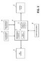
- FIG. 1is a diagram of a convey system, particularly illustrating a location of a supply pressure P 1 , a convey pressure P 2 , a control valve, and an airlock;
- FIG. 2is a schematic of an air control system of embodiments of the present invention.
- FIG. 3is schematic of a controller of the air control system of embodiments of the present invention.
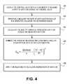
- FIG. 4is a flow chart of steps of determining a rate of air flow for the convey system of embodiments of the present invention.
- references to “one embodiment,” “an embodiment,” or “embodiments”mean that the feature or features being referred to are included in at least one embodiment of the technology.
- references to “one embodiment,” “an embodiment,” or “embodiments” in this descriptiondo not necessarily refer to the same embodiment and are also not mutually exclusive unless so stated and/or except as will be readily apparent to those skilled in the art from the description.
- a feature, structure, act, etc. described in one embodimentmay also be included in other embodiments, but is not necessarily included.
- the present technologycan include a variety of combinations and/or integrations of the embodiments described herein.
- Embodiments of the present inventioncomprise a low pressure continuous dense phase convey system 10 having a convey line 12 , an inlet 14 to the convey line 12 for introduction of pressurized air into the system, an airlock 16 associated with a feedpoint 18 of the convey line 12 for introduction of particulate into the system, and a non-critical air control system 20 for controlling a rate of air flow through the convey system 10 .
- Pressurized airflows through the convey line 12 from an upstream position 22 and to a downstream position 24 .
- the pressurized air moving through the convey line 12serves to move particulate through the convey system 10 .
- a rate of air flow through the convey line 12dictates a volume of particulate moved through the system 10 and a distance the particulate can be moved.
- Common particulatesinclude pet food, grain, sugar, flour, and the like.
- the particulateis initially held in a hopper 26 , as is known in the art.
- the particulateis fed or otherwise metered to the convey line 12 via the airlock 16 .
- some pressurized airleaks from the convey line 12 , resulting in a decrease in the air flow rate proximate the airlock 16 .
- the particulateexits to a collector 28 at the end of the convey line 12 .
- a distance of the convey line 12depends on the particular convey system 10 employed, but convey lines often can be several hundred to thousands of feet in length.
- the air control system 20 of embodiments of the present inventioncomprises an air source 30 for supplying pressurized air into the convey system 10 ; a control valve 32 operable to selectively adjust the rate of flow of air received from the air source 30 to produce a non-critical air flow; a first pressure transducer 34 for sensing a supply pressure, P 1 , produced by the air source 30 ; a second pressure transducer 36 for sensing a convey pressure, P 2 , proximate the airlock 16 ; and a controller 38 operable to receive first and second signals respectively corresponding to the sensed air pressures for the first and second pressure transducers 34 , 36 , and based on a non-critical flow equation, control output of the air source 30 to obtain a desired supply pressure P 1 , and positioning of the control valve 32 to obtain a desired air flow rate immediately downstream of the control valve 32 .
- the air source 30is any source of pressurized air.
- the air pressure used to convey particulateis relatively low, usually approximately 10-20 psi.
- the velocity of the particulates through the convey system 10is also relatively low, usually approximately 400-1800 feet per minute (“FPM”).
- the air source 30is preferably a positive displacement blower controlled through a variable frequency drive (“VFD”). Blowers equipped with a VFD are well known, and in embodiments of the present invention, the speed of the blower may be adjusted to provide a known supply pressure P 1 to the control valve 32 .
- VFDvariable frequency drive
- the air source 30is positioned upstream of the inlet 14 of the convey system 10 . Further, the air source 30 is electronically coupled with the controller 38 for electronic adjustment of the air source speed, as illustrated in FIG. 3 . However, the air source 30 speed may be adjusted mechanically. It should be appreciated that other types of pressurized air sources, other than blowers, may be used.
- the control valve 32 of the air control system 20is operable to meter the air flow through the valve 32 to effect a desired air flow rate exiting the valve 32 .
- the control valve 32is an infinite position sonic nozzle (“IPSN”), such as the MACTURITM manufactured by MAC Equipment, Inc. of Kansas City, Mo., which is the assignee of the present invention.
- the control valve 32is preferably electronically coupled with the controller 38 for adjusting the position of the control valve 32 based on a desired rate of air flow, as illustrated in FIG. 3 .
- the “position” of the control valve 32refers to a physical change in the control valve's metering mechanism to effect the desired rate of air flow.
- control valvescharacterize the position of the valve as the percentage that the valve is “open” or “closed,” such as, for example, a valve that is 40% open.
- Control valves other than ISPNsmay be used, although ISPNs are known to be an efficient metering valve.
- control valve 32is positioned generally immediately downstream of the air source 30 and immediately upstream of the inlet 14 of the convey system 10 .
- control valve 32is preferably directly coupled to the inlet 14 of the convey system 10 , such that the metered air exiting the control valve 32 is supplied to the convey line 12 .
- the first and second pressure transducers 34 , 36are substantially similar and comprise any suitable pressure transducer for sensing a pressure at a particular location in the convey system 10 .
- the transducers 34 , 36are electronically coupled with the controller 38 .
- Each transducer 34 , 36senses the pressure at the particular location, and a signal comprising the sensed pressure is relayed to the controller 38 .
- the controller 38uses the sensed pressure signals to control the air pressure produced by the air source 30 and the metering of the air flow through the control valve 32 .
- Suitable pressure transducers 34 , 36are manufactured by Setra Systems, Inc. of Boxborough, Mass.
- the first pressure transducer 34is positioned downstream of the air source 30 and upstream of the control valve 32 and inlet 14 so as to sense the supply pressure P 1 being produced by the air source 30 .
- the second pressure transducer 36is positioned downstream of the inlet 14 and proximate the airlock 16 (either on the airlock transition or immediately upstream) so as to sense the convey pressure P 2 .
- the second pressure transducer 36is preferably positioned at a location proximate the airlock 16 so as to determine the air pressure in the convey system 10 after the air leakage at the airlock 16 .
- the controller 38 of the air control system 20is a programmable logic controller that includes a processing element 40 and a memory element 42 .
- the controller 38may also include a user interface 44 for access by a user of the invention and for control, input, or communication with the processing and memory elements 40 , 42 of the controller 38 and the various external components.
- the controller 38is an Allen-Bradley SLC 500. Some of the functions that the controller 38 handles include receiving a first signal from the first pressure transducer 34 representing a first sensed pressure and receiving a second signal from the second pressure transducer 36 representing a second sensed pressure.
- the controller 38Upon receiving the first and second pressure signals, the controller 38 is operable to process the pressure signals and determine a desired control valve 32 position using the non-critical flow equations discussed in more detail below. The controller 38 then sends a control signal to the control valve 32 to instruct positioning of the valve. In even further embodiments of the invention, the controller 38 is coupled with and operable to control the speed of the air source 30 so as to emit a known supply pressure P 1 .
- the processing element 40may execute computer programs, software, code, instructions, algorithms, applications, or firmware, and combinations thereof.
- the processing element 40may include processors, microprocessors, microcontrollers, field-programmable gate arrays (FPGAs), application-specific integrated circuits (ASICs), combinations thereof, and the like, and may be implemented using hardware description languages (HDLs), such as Verilog and VHDL.
- HDLshardware description languages
- the memory element 42generally stores data to be utilized by the air control system 20 .
- the datamay include computer code, programs, applications, system settings, system preferences, measured data, combinations thereof, and the like.
- the memory element 42may be configured to communicate with the processing element 40 .
- the memory element 42 of the controller 38includes data storage components, which may comprise a non-transitory computer-readable storage medium (or “computer-readable medium”) capable of storing the computer programs, software, code, instructions, algorithms, applications, or firmware for use by or in connection with the processing element 40 .
- the computer-readable mediummay include random-access memory (RAM) such as static RAM (SRAM) or dynamic RAM (DRAM), cache memory, read-only memory (ROM), flash memory, hard-disk drives, compact disc ROM (CDROM), digital video disc (DVD), or Blu-RayTM, combinations thereof, and the like.
- RAMrandom-access memory
- SRAMstatic RAM
- DRAMdynamic RAM
- cache memoryread-only memory
- ROMread-only memory
- flash memoryhard-disk drives
- CDROMcompact disc ROM
- DVDdigital video disc
- Blu-RayTMcombinations thereof, and the like.
- the controller 38may include one or more device ports (not shown) for providing communication between the processing element 40 and the air source 30 , the first and second pressure transducers 34 , 36 , the control valve 32 , and any other external component.
- the device portmay include parallel ports, serial ports, USB ports, IEEE 1394 high-speed serial bus ports, combinations thereof, and the like.
- the device portmay connect to the external components through a wire or cable, optical fiber, or wirelessly.
- An exemplary device portmay include a plurality of USB ports.
- the processing element 40may also transmit signals through the device port to the external components in order to control the functions of the components or turn the components on or off.
- the processing elementmay receive the first and second pressure signals from the first and second pressure transducers 34 , 36 , and based on the calculations performed by the controller, transmit a control signal to the control valve 32 for positioning of the valve or a control signal to the air source 30 for effecting a different air pressure.
- the processing element 40may transmit signals to the external components either automatically, at a given time, or when a certain condition is met.
- the controller 38may further be connected with an external computing element 46 for downloading flow performance characteristics or other convey system information for use and analysis by the user of the invention or for receiving program instructions or other information for storage on the controller's memory element 42 .
- the controller 38is employed to obtain a desired air flow rate.
- the desired air flow rateis based on a desired convey velocity, a length of the convey line 12 , and the calculated air leakage through the airlock 16 .
- the computer program stored on the memory element 42 of the controller 38receives these inputs to calculate the desired air flow rate, or, alternatively, the desired input rate is input to the program.
- the controller 38then instructs the position of the valve 32 to obtain the calculated desired air flow rate.
- Embodiments of the present inventionobtain a very high accuracy of the actual rate of air flow downstream of the control valve 32 versus the expected rate of air flow. Most prior art convey systems obtain no greater than approximately 10% accuracy, whereas the present invention obtains approximately 3% accuracy. Thus, the actual rate of air flow downstream of the control valve 32 is within 3% of the expected rate of air flow.
- a pressure differential across the control valve 32is preferably maintained at a minimum specified value.
- the pressure differential, ⁇ P, across the control valve 32is the difference in the pressures P 2 and P 1 . Because the first and second pressure transducers 34 , 36 are positioned on opposite flow sides of the control valve 32 , the present invention is operable to determine the pressure differential.
- embodiments of the present inventionmaintain a ratio of P 1 to P 2 as less than 1.5:1, less than 1.4:1, less than 1.3:1, less than 1.25:1, less than 1.2:1, less than 1.15:1, less than 1.1:1, or less than 1.05:1.
- the incremental value of the supply pressure P 1 produced by the air source 30 over the actual convey pressure P 2 at the airlock 16is relatively small.
- the differential pressure ⁇ Pis 0.5-2.5 psi, 1-2 psi, or 1.2-1.8 psi.
- embodiments of the present inventionemploy a control sequence that repeatedly monitors the supply pressure P 1 and the convey pressure P 2 .
- the first and second pressure transducers 34 , 36perform approximately 2-10 scans per second, such that the controller 38 receives pressure signals from the transducers approximately every 0.1-0.5 seconds.
- the controller 38uses the received pressure values to repeatedly control, and if need be, change, the position of the control valve 32 to obtain the desired air flow rate.
- the controller 38changes the discharge pressure from the air source 30 .
- the air control system 20 of the present inventionfluctuates the air pressure discharged by the air source 30 no more than ⁇ 0.2-3%, ⁇ 0.6-1.8%, or ⁇ 1% within any operating cycle (i.e., from the time the convey system 10 begins conveying particulate to the time it ceases conveying particulate) or from the previous control instruction or change of the air pressure.
- the supply pressure discharged from the air source 30is held constant and a mechanical relief valve is used to vent the excess air
- embodiments of the present inventiondo not hold the air source discharge constant.
- the air source pressure and the control valve positionare set to obtain a desired air flow rate. Consequently, in a non-critical air flow system, the rate of air flow is a function of the supply pressure P 1 , the convey pressure P 2 , and the control valve position, as opposed to only being a function of the control valve position in a critical air flow system.
- the pressure differential across the control valve 32to a minimum specified value, the air flow through the valve 32 remains non-critical and the air source discharge pressure is minimized. Additional advantages beyond energy consumption include reduced noise from the air source 30 , such as the blower, and reduced heat generation.
- control valve 32may be any valve for metering the rate of air flow exiting the valve.
- Each type of valve 32e.g., a butterfly valve versus an ISPN, will have a different critical flow model, Q(critical), which can be determined through testing or which is, more commonly, provided by the manufacturer of the valve.
- Q(critical)critical flow model
- For non-critical air flowApplicant has found Equation (1) to be a statistically correct model, regardless of the type of control valve employed. Nonetheless, when applying Equation (1) for non-critical flow, even for a particular type, brand, or model of control valve, each valve will have its own flow performance characteristics, namely the constants x and y in Equation (1). The flow performance characteristics for the particular valve must then be determined. To determine such characteristics, the rate of air flow at every control valve position and differential pressure across the valve in a statistical sample size must be measured.
- Equation (2)For Applicant's MACTURITM branded control nozzle, Q(critical) is best modeled with the following Equation (2):
- embodiments of the present inventionprovide a testing methodology for determining the non-critical flow performance characteristics, x and y, of a particular valve.
- the control valve 32is coupled with a flow meter to measure a rate of air flow exiting the valve 32 .
- the rate of air flow from the valve 32is measured for a variety of operating parameters, including supply pressure P 1 , convey pressure P 2 , and position.
- a range of values of each of supply pressure P 1 , convey pressure P 2 , and valve positionis determined based on a type and volume of particulate being moved, the convey line length, and other variables.
- iterative testing for the range of values of each operating parameteris performed.
- Equation (1)incorporates the critical flow equation for the particular valve, and the critical flow equation is a function of, at the least, valve position.
- Equation (1)Applicant has obtained less than an approximately 3% error between the calculated rate of air flow and the actual rate of air flow.
- the method and computer program of the present inventioncan also input a desired air flow and known P 1 and P 2 , and then apply Equation (1) to determine the necessary valve position to achieve the desired air flow.
- Equation (1)improves the prediction of non-critical air flow significantly over known critical flow equations.
- the critical flow equationhad an average absolute error of 4.85%, while the non-critical flow equation had an average absolute error of 1.74%.
- the ratio of P 2 to P 1exceeded 90%, which is well above the results achieved using critical air flow equations and a highly efficient control valve.
- Embodiments of the present inventionregardless of the control valve employed, routinely achieve a ratio of P 2 to P 1 of greater than or equal to 90%, greater than or equal to 93%, or greater than or equal to 95%.
- P 2is greater than or equal to 90% of P 1 , such that the differential pressure ⁇ P is less than 10% of P 1 .
- the air source 30does not need to do as much work, which reduces energy consumption, heat generation, and noise from the air source 30 .
- a certain convey line 12 sizecan operate at a higher downstream pressure, whereby conveying more particulate a longer distance.
- the air source 30has a maximum air pressure value at which it can operate.
- max P 1is fixed. If operating in a critical air flow control system, then there is a maximum P 2 value that is dependent on the max P 1 value. In contrast, if operating in a non-critical air flow control system, then P 1 does not reach its maximum as quickly, which allows for more particulate throughput relative to P 2 . If P 2 can be increased relatively larger, then either more particulate can be added to and moved through the convey system 10 , or the same amount of particulate can be conveyed a longer distance.
- alternative embodiments of the present inventionemploy an air header (not shown) immediately downstream of the air source 30 and first pressure transducer 34 .
- a plurality of control valves 32can be mounted to the air header to fluidly communicate air to multiple convey systems.
- a single air source 30can supply air to the air header, and thus, the plurality of control valves, such that the single air source can supply the convey air to multiple convey systems.
Landscapes
- Engineering & Computer Science (AREA)
- Mechanical Engineering (AREA)
- Physics & Mathematics (AREA)
- General Physics & Mathematics (AREA)
- Automation & Control Theory (AREA)
- Flow Control (AREA)
- Fluid-Pressure Circuits (AREA)
- Air Transport Of Granular Materials (AREA)
Abstract
Description
where Pais atmospheric pressure, and “Efficiency” is a percentage value representing the efficiency of the control valve, which is known. The Efficiency of a valve is usually referred to as the value to which P2 can rise in a critical air flow system before the rate of air flow is decreased as a result. For example, in an inefficient valve, P2 can only rise to 50%-60% of P1, whereas in highly efficient valve, P2 can rise to approximately 80%-85% of P1.
where
- Qnc=Non-Critical Rate of Air Flow in SCFM
- Q(critical)=Critical Rate of Air Flow in SCFM
- P1=Supply Pressure in PSIA
- P2=Convey Pressure in PSIA
- x=Non-Critical Flow Constant
- y=Non-Critical Flow Constant
Where Cv=MACTURI™ Flow Variable, which is then developed through testing as follows:
Where
- K1=slope of Cvversus % Open Curve
- K2=intercept of Cvversus % Open Curve.
| TABLE 1 | |||
| MACTURI ™ Model | II | ||
| # of Points | 96 | ||
| Minimum P1, PSIG | 3.0 | ||
| Maximum P1, PSIG | 13.0 | ||
| Minimum Stroke, % | 40 | ||
| Maximum Stroke, % | 70 | ||
| Minimum P2/P1 | 0.825 | ||
| Maximum P2/P1 | 0.945 | ||
| Average Error | 1.74 | ||
| (Using Equation (1)) | |||
| Average Error | 4.85 | ||
| (Using Critical Flow Equation) | |||
| x | 0.70 | ||
| y | 0.17 | ||
| TABLE 2 | ||
| Non-Critical Flow Data | ||
| MACTURI ™ | Avg P1 | Stroke | P2/P1 | P2/P1 | Average | |||
| Model | PSIG | % | Min | Max | # of Points | Error, % | x | y |
| III-H (Original) | 80.1 | 10 | 0.909 | 0.920 | 2 | 0.16 | 0.83 | 0.09 |
| III-H (Original) | 82.2 | 40 | 0.886 | 0.920 | 4 | 0.36 | 0.81 | 0.12 |
| III-H | 29.9 | 0 | 0.872 | 0.925 | 5 | 0.43 | 0.70 | 0.20 |
| III-H | 30.2 | 25 | 0.853 | 0.922 | 6 | 0.52 | 0.84 | 0.19 |
| III-H | 29.9 | 50 | 0.835 | 0.946 | 7 | 0.97 | 0.83 | 0.18 |
| III-H | 29.9 | 100 | 0.888 | 0.940 | 5 | 0.35 | 0.79 | 0.16 |
| III-H | 80.3 | 100 | 0.886 | 0.924 | 4 | 0.54 | 0.85 | 0.13 |
| III-L | 30.1 | 25 | 0.901 | 0.945 | 4 | 0.37 | 0.68 | 0.19 |
| III-L | 29.7 | 50 | 0.904 | 0.955 | 6 | 0.79 | 0.72 | 0.18 |
| III-L | 30.4 | 100 | 0.903 | 0.937 | 4 | 0.45 | 0.76 | 0.16 |
| III-L | 79.6 | 100 | 0.896 | 0.914 | 3 | 0.18 | 0.83 | 0.12 |
| I (Original) | 55.0 | 70 | 0.951 | 0.963 | 2 | 0.61 | 0.62 | 0.18 |
| I (Original) | 80.0 | 70 | 0.913 | 0.963 | 4 | 0.33 | 0.70 | 0.16 |
Claims (6)
Priority Applications (3)
| Application Number | Priority Date | Filing Date | Title |
|---|---|---|---|
| US13/099,123US8747029B2 (en) | 2010-05-03 | 2011-05-02 | Low pressure continuous dense phase convey system using a non-critical air control system |
| EP11778162.5AEP2566798A4 (en) | 2010-05-03 | 2011-05-03 | Low pressure continuous dense phase convey system using a non-critical air control system |
| PCT/US2011/034983WO2011140077A2 (en) | 2010-05-03 | 2011-05-03 | Low pressure continuous dense phase convey system using a non-critical air control system |
Applications Claiming Priority (2)
| Application Number | Priority Date | Filing Date | Title |
|---|---|---|---|
| US33067710P | 2010-05-03 | 2010-05-03 | |
| US13/099,123US8747029B2 (en) | 2010-05-03 | 2011-05-02 | Low pressure continuous dense phase convey system using a non-critical air control system |
Publications (2)
| Publication Number | Publication Date |
|---|---|
| US20110268510A1 US20110268510A1 (en) | 2011-11-03 |
| US8747029B2true US8747029B2 (en) | 2014-06-10 |
Family
ID=44858364
Family Applications (1)
| Application Number | Title | Priority Date | Filing Date |
|---|---|---|---|
| US13/099,123Active2032-10-01US8747029B2 (en) | 2010-05-03 | 2011-05-02 | Low pressure continuous dense phase convey system using a non-critical air control system |
Country Status (3)
| Country | Link |
|---|---|
| US (1) | US8747029B2 (en) |
| EP (1) | EP2566798A4 (en) |
| WO (1) | WO2011140077A2 (en) |
Cited By (13)
| Publication number | Priority date | Publication date | Assignee | Title |
|---|---|---|---|---|
| US20140000720A1 (en)* | 2012-06-29 | 2014-01-02 | General Electric Company | Apparatus and method of delivering a fluid using a non-mechanical eductor pump and lock hopper |
| US9181044B1 (en)* | 2012-02-14 | 2015-11-10 | Horizon Systems, Inc. | Mechanically controlled vacuum throttle for a continuous dense phase particulate material conveying system and method |
| US20150321843A1 (en)* | 2012-05-03 | 2015-11-12 | Envac Ab | Method of controlling operation of a pneumatic conveying system |
| US9611106B2 (en)* | 2015-06-01 | 2017-04-04 | Xerex Ab | Device and system for pneumatic transport of material |
| US9745149B2 (en)* | 2015-03-19 | 2017-08-29 | Ipeg, Inc. | Material delivery system |
| US10040644B2 (en)* | 2016-05-17 | 2018-08-07 | Diebold Nixdorf, Incorporated | Empties transport system and empties return system for suction of containers |
| US10399797B2 (en)* | 2016-08-29 | 2019-09-03 | Shick Solutions, Inc. | Flow control apparatus for carrier fluid |
| US11111087B1 (en)* | 2020-08-26 | 2021-09-07 | Xiongqing Yu | Transfer system for soft gels |
| US11161699B2 (en)* | 2019-06-18 | 2021-11-02 | Braskem America, Inc. | Solids conveying with multi-diameter piping circuit |
| US11656117B1 (en)* | 2019-05-14 | 2023-05-23 | Mississippi Lime Company | Test system for rotary airlocks |
| US11713201B1 (en)* | 2022-02-18 | 2023-08-01 | Sk On Co., Ltd. | Vacuum-type powder transfer system and method |
| US11858757B2 (en)* | 2021-12-28 | 2024-01-02 | Mitsubishi Heavy Industries, Ltd. | Control device, granular material supply system, control method, and program |
| US20240308787A1 (en)* | 2021-05-26 | 2024-09-19 | Balsu Gida Sanayi Ve Ticaret Anonim Sirketi | Carrying system for use in displacement of hazelnut |
Families Citing this family (10)
| Publication number | Priority date | Publication date | Assignee | Title |
|---|---|---|---|---|
| EP2254818A1 (en)* | 2008-01-28 | 2010-12-01 | Johann Haberl | Tubing conduit system, a method for control thereof and the use thereof |
| NL1039764C2 (en)* | 2012-08-17 | 2014-02-18 | J O A Technology Beheer B V | A method of, a control system, a device, a sensor and a computer program product for controlling transport of fibrous material in a transport line of a pneumatic conveying system. |
| US10184678B2 (en) | 2013-09-06 | 2019-01-22 | Carrier Corporation | System and method for measuring duct leakage in a HVAC system |
| CN104014410B (en)* | 2014-06-24 | 2016-03-02 | 玉石塑粉有限公司 | Ultrafine powder paint separation equipment |
| CA2904783C (en)* | 2014-11-04 | 2020-07-14 | Cnh Industrial Canada, Ltd. | Tank pressurization control for air carts |
| CN105383935A (en)* | 2015-10-29 | 2016-03-09 | 长安大学 | Thick paste conveying device |
| US10494200B2 (en) | 2016-04-25 | 2019-12-03 | Chevron Phillips Chemical Company Lp | Measurement of product pellets flow rate |
| GB201906310D0 (en)* | 2019-05-03 | 2019-06-19 | Schenck Process Uk Ltd | Material conveying apparatus with shut down valves |
| CN110510409B (en)* | 2019-09-30 | 2020-06-16 | 于志洲 | Remote isobaric material conveying system |
| CN116819951B (en)* | 2023-08-28 | 2023-11-24 | 新光维医疗科技(苏州)股份有限公司 | Flow control method, system, device and storage medium of gas delivery system |
Citations (25)
| Publication number | Priority date | Publication date | Assignee | Title |
|---|---|---|---|---|
| US3875955A (en)* | 1974-01-10 | 1975-04-08 | Process Systems | Digital fluid flow rate measurement or control system |
| US4019783A (en)* | 1974-08-06 | 1977-04-26 | Lutz Tilo Kayser | Process and apparatus for continuously conveying particulate material |
| US4122611A (en)* | 1976-02-19 | 1978-10-31 | Air Industrie | Apparatus for the continuous thermal treatment of a product moving through an enclosed space |
| US4284032A (en)* | 1978-11-14 | 1981-08-18 | Gema Ag | Pneumatic conveyor of adjustable conveyance capacity for powdered to granular bulk material |
| US4362442A (en)* | 1980-04-14 | 1982-12-07 | Dundee Cement Company | Venturi barge unloading system |
| US4379663A (en)* | 1980-09-22 | 1983-04-12 | Mac Equipment, Inc. | Vacuum sequencing system with weight controlled material draw cycle |
| US4506834A (en)* | 1980-11-21 | 1985-03-26 | Fiber Dynamics Ab | Method and device for dispersing material |
| US4521139A (en)* | 1981-07-17 | 1985-06-04 | Brennstoffinstitut Freiberg | Method of regulating mass streams |
| US4722363A (en)* | 1986-06-04 | 1988-02-02 | Atlantic Richfield Company | Additive injection system for fluid transmission pipelines |
| US4758117A (en)* | 1984-12-28 | 1988-07-19 | Kawasaki Steel Corp. | Method for the transportation of a particulate material at controlled rate |
| US4875810A (en)* | 1985-10-21 | 1989-10-24 | Canon Kabushiki Kaisha | Apparatus for controlling fine particle flow |
| US5350257A (en)* | 1992-09-18 | 1994-09-27 | Mac Equipment, Inc. | Pneumatic conveyor for granular materials |
| US5603751A (en)* | 1995-06-02 | 1997-02-18 | Mac Equipment, Inc. | Method and apparatus for removing particulate material from a wood drying system |
| JPH09278183A (en) | 1996-04-16 | 1997-10-28 | Mitsubishi Nuclear Fuel Co Ltd | Pulverulent body transporting device |
| US5813801A (en)* | 1996-06-28 | 1998-09-29 | Mac Equipment, Inc. | Dense phase particulate conveying system and method with continuous air leakage management |
| JPH11130257A (en) | 1997-10-31 | 1999-05-18 | Akatake Engineering Kk | Pneumatic carrier device for powder and grain |
| JP2000015203A (en) | 1998-06-30 | 2000-01-18 | Lion Corp | Residue recovery system in high viscosity fluid transfer piping |
| US6062774A (en)* | 1996-05-28 | 2000-05-16 | Neu Transf'air | Method for automatically detecting stability limit operation of a bulk product pneumatic conveyor installation operating in dense phase |
| US6481935B2 (en)* | 2000-02-10 | 2002-11-19 | Eastman Chemical Company | Device for establishing optimal material flow rate for unloading materials |
| KR20050091186A (en) | 2004-03-11 | 2005-09-15 | 고등기술연구원연구조합 | Apparatus for preventing a granular grain transferring pipe from blocking |
| US7101120B2 (en)* | 2004-09-15 | 2006-09-05 | Jurkovich John C | Apparatus and method for controlling fluid flows for pneumatic conveying |
| KR20070119778A (en) | 2006-06-16 | 2007-12-21 | 기아자동차주식회사 | Granular fluid conveying system |
| US7537375B2 (en)* | 2003-07-31 | 2009-05-26 | Lextron, Inc. | Method and apparatus for administering micro-ingredient feed additives to animal feed rations |
| US20110232547A1 (en)* | 2007-11-16 | 2011-09-29 | Paul Wurth S.A. | Injection system for solid particles |
| US20140000720A1 (en)* | 2012-06-29 | 2014-01-02 | General Electric Company | Apparatus and method of delivering a fluid using a non-mechanical eductor pump and lock hopper |
Family Cites Families (1)
| Publication number | Priority date | Publication date | Assignee | Title |
|---|---|---|---|---|
| JP4102564B2 (en)* | 2001-12-28 | 2008-06-18 | 忠弘 大見 | Improved pressure flow controller |
- 2011
- 2011-05-02USUS13/099,123patent/US8747029B2/enactiveActive
- 2011-05-03WOPCT/US2011/034983patent/WO2011140077A2/enactiveApplication Filing
- 2011-05-03EPEP11778162.5Apatent/EP2566798A4/ennot_activeWithdrawn
Patent Citations (25)
| Publication number | Priority date | Publication date | Assignee | Title |
|---|---|---|---|---|
| US3875955A (en)* | 1974-01-10 | 1975-04-08 | Process Systems | Digital fluid flow rate measurement or control system |
| US4019783A (en)* | 1974-08-06 | 1977-04-26 | Lutz Tilo Kayser | Process and apparatus for continuously conveying particulate material |
| US4122611A (en)* | 1976-02-19 | 1978-10-31 | Air Industrie | Apparatus for the continuous thermal treatment of a product moving through an enclosed space |
| US4284032A (en)* | 1978-11-14 | 1981-08-18 | Gema Ag | Pneumatic conveyor of adjustable conveyance capacity for powdered to granular bulk material |
| US4362442A (en)* | 1980-04-14 | 1982-12-07 | Dundee Cement Company | Venturi barge unloading system |
| US4379663A (en)* | 1980-09-22 | 1983-04-12 | Mac Equipment, Inc. | Vacuum sequencing system with weight controlled material draw cycle |
| US4506834A (en)* | 1980-11-21 | 1985-03-26 | Fiber Dynamics Ab | Method and device for dispersing material |
| US4521139A (en)* | 1981-07-17 | 1985-06-04 | Brennstoffinstitut Freiberg | Method of regulating mass streams |
| US4758117A (en)* | 1984-12-28 | 1988-07-19 | Kawasaki Steel Corp. | Method for the transportation of a particulate material at controlled rate |
| US4875810A (en)* | 1985-10-21 | 1989-10-24 | Canon Kabushiki Kaisha | Apparatus for controlling fine particle flow |
| US4722363A (en)* | 1986-06-04 | 1988-02-02 | Atlantic Richfield Company | Additive injection system for fluid transmission pipelines |
| US5350257A (en)* | 1992-09-18 | 1994-09-27 | Mac Equipment, Inc. | Pneumatic conveyor for granular materials |
| US5603751A (en)* | 1995-06-02 | 1997-02-18 | Mac Equipment, Inc. | Method and apparatus for removing particulate material from a wood drying system |
| JPH09278183A (en) | 1996-04-16 | 1997-10-28 | Mitsubishi Nuclear Fuel Co Ltd | Pulverulent body transporting device |
| US6062774A (en)* | 1996-05-28 | 2000-05-16 | Neu Transf'air | Method for automatically detecting stability limit operation of a bulk product pneumatic conveyor installation operating in dense phase |
| US5813801A (en)* | 1996-06-28 | 1998-09-29 | Mac Equipment, Inc. | Dense phase particulate conveying system and method with continuous air leakage management |
| JPH11130257A (en) | 1997-10-31 | 1999-05-18 | Akatake Engineering Kk | Pneumatic carrier device for powder and grain |
| JP2000015203A (en) | 1998-06-30 | 2000-01-18 | Lion Corp | Residue recovery system in high viscosity fluid transfer piping |
| US6481935B2 (en)* | 2000-02-10 | 2002-11-19 | Eastman Chemical Company | Device for establishing optimal material flow rate for unloading materials |
| US7537375B2 (en)* | 2003-07-31 | 2009-05-26 | Lextron, Inc. | Method and apparatus for administering micro-ingredient feed additives to animal feed rations |
| KR20050091186A (en) | 2004-03-11 | 2005-09-15 | 고등기술연구원연구조합 | Apparatus for preventing a granular grain transferring pipe from blocking |
| US7101120B2 (en)* | 2004-09-15 | 2006-09-05 | Jurkovich John C | Apparatus and method for controlling fluid flows for pneumatic conveying |
| KR20070119778A (en) | 2006-06-16 | 2007-12-21 | 기아자동차주식회사 | Granular fluid conveying system |
| US20110232547A1 (en)* | 2007-11-16 | 2011-09-29 | Paul Wurth S.A. | Injection system for solid particles |
| US20140000720A1 (en)* | 2012-06-29 | 2014-01-02 | General Electric Company | Apparatus and method of delivering a fluid using a non-mechanical eductor pump and lock hopper |
Non-Patent Citations (1)
| Title |
|---|
| Notification of Transmittal of the International Search Report and the Written Opinion of the International Searching Authority, or the Declaration dated Jan. 6, 2012; International Application No. PCT/US2011/034983; International Filing Dated: May 3, 2011; Applicant: Mac Equipment, Inc. |
Cited By (21)
| Publication number | Priority date | Publication date | Assignee | Title |
|---|---|---|---|---|
| US10752451B2 (en)* | 2012-02-14 | 2020-08-25 | Horizon Systems, Inc. | Mechanically controlled vacuum throttle for a continuous dense phase particulate material conveying system and method |
| US9181044B1 (en)* | 2012-02-14 | 2015-11-10 | Horizon Systems, Inc. | Mechanically controlled vacuum throttle for a continuous dense phase particulate material conveying system and method |
| US20170174447A1 (en)* | 2012-02-14 | 2017-06-22 | Horizon Systems, Inc. | Mechanically controlled vacuum throttle for a continuous dense phase particulate material conveying system and method |
| US20150321843A1 (en)* | 2012-05-03 | 2015-11-12 | Envac Ab | Method of controlling operation of a pneumatic conveying system |
| US9302849B2 (en)* | 2012-05-03 | 2016-04-05 | Envac Ab | Method of controlling operation of a pneumatic conveying system |
| US9086164B2 (en)* | 2012-06-29 | 2015-07-21 | General Electric Company | Apparatus and method of delivering a fluid using a non-mechanical eductor pump and lock hopper |
| US20140000720A1 (en)* | 2012-06-29 | 2014-01-02 | General Electric Company | Apparatus and method of delivering a fluid using a non-mechanical eductor pump and lock hopper |
| US9745149B2 (en)* | 2015-03-19 | 2017-08-29 | Ipeg, Inc. | Material delivery system |
| US9611106B2 (en)* | 2015-06-01 | 2017-04-04 | Xerex Ab | Device and system for pneumatic transport of material |
| US10040644B2 (en)* | 2016-05-17 | 2018-08-07 | Diebold Nixdorf, Incorporated | Empties transport system and empties return system for suction of containers |
| US10399797B2 (en)* | 2016-08-29 | 2019-09-03 | Shick Solutions, Inc. | Flow control apparatus for carrier fluid |
| US11656117B1 (en)* | 2019-05-14 | 2023-05-23 | Mississippi Lime Company | Test system for rotary airlocks |
| US11161699B2 (en)* | 2019-06-18 | 2021-11-02 | Braskem America, Inc. | Solids conveying with multi-diameter piping circuit |
| US20220009728A1 (en)* | 2019-06-18 | 2022-01-13 | Braskem America, Inc. | Solids conveying with multi-diameter piping circuit |
| US11753258B2 (en)* | 2019-06-18 | 2023-09-12 | Braskem America, Inc. | Solids conveying with multi-diameter piping circuit |
| US11111087B1 (en)* | 2020-08-26 | 2021-09-07 | Xiongqing Yu | Transfer system for soft gels |
| US20240308787A1 (en)* | 2021-05-26 | 2024-09-19 | Balsu Gida Sanayi Ve Ticaret Anonim Sirketi | Carrying system for use in displacement of hazelnut |
| US12264021B2 (en)* | 2021-05-26 | 2025-04-01 | Balsu Gida Sanayi Ve Ticaret Anonim Sirketi | Carrying system for use in displacement of hazelnut |
| US11858757B2 (en)* | 2021-12-28 | 2024-01-02 | Mitsubishi Heavy Industries, Ltd. | Control device, granular material supply system, control method, and program |
| US11713201B1 (en)* | 2022-02-18 | 2023-08-01 | Sk On Co., Ltd. | Vacuum-type powder transfer system and method |
| US11897709B2 (en) | 2022-02-18 | 2024-02-13 | Sk On Co., Ltd. | Vacuum-type powder transfer system and method |
Also Published As
| Publication number | Publication date |
|---|---|
| EP2566798A4 (en) | 2018-04-04 |
| US20110268510A1 (en) | 2011-11-03 |
| WO2011140077A3 (en) | 2012-03-01 |
| EP2566798A2 (en) | 2013-03-13 |
| WO2011140077A2 (en) | 2011-11-10 |
Similar Documents
| Publication | Publication Date | Title |
|---|---|---|
| US8747029B2 (en) | Low pressure continuous dense phase convey system using a non-critical air control system | |
| US10801867B2 (en) | Method and apparatus for self verification of pressured based mass flow controllers | |
| CN107966235B (en) | High-precision pressure measurement system with variable reference pressure | |
| TW200710374A (en) | Absolute flow rate calibration system in flow rate control device | |
| CN103125012B (en) | Substrate Handling System | |
| CN105074415B (en) | Air pressure loop for Tire testing device | |
| CN113049255B (en) | Flow regulating device, pre-adjusting method and testing method for liquid flow test | |
| JP2019163163A (en) | Vacuum conveyor system | |
| CN107004620A (en) | The system and method that load lock gate valve is opened under pressure needed for after exhaust | |
| JP2002326161A (en) | Shot peening method, and device thereof | |
| US11434934B2 (en) | System and method for end position damping | |
| CN107532498B (en) | Automatic Performance Adjustment for Diesel Exhaust Treatment Fluid Dosing Device | |
| CN114680372A (en) | Pneumatic conveying control method, computer readable medium, pneumatic conveying control system and tobacco shred pneumatic conveying system | |
| CN204197318U (en) | A kind of parallel type packaging blanking device that can regulate charge air | |
| US20250264891A1 (en) | Flow ratio controllers and gas distribution systems utilizing flow ratio controllers | |
| US20250264892A1 (en) | Flow ratio controllers with mass accumulation compensation and gas distribution systems utilizing mass accumulation compensation | |
| CN202582216U (en) | Diffusion furnace chamber atmosphere stabilizing device | |
| CN222978918U (en) | Gas-solid two-phase measuring equipment calibration device | |
| JP2008143041A (en) | Resin weighing device | |
| JP2002265053A (en) | Reducer for transport pipe | |
| US11327510B2 (en) | Multi-chamber rate-of-change system for gas flow verification | |
| US12253812B2 (en) | Powder replenisher and powder replenishing method | |
| CN119370612A (en) | A method for adjusting the amount of gas delivered and a related device | |
| JP2515648B2 (en) | Pressure control device for blow-out wind tunnel | |
| JP2005189057A (en) | Determinate quantity transportation method for powder and grain |
Legal Events
| Date | Code | Title | Description |
|---|---|---|---|
| AS | Assignment | Owner name:MAC EQUIPMENT, INC., MISSOURI Free format text:ASSIGNMENT OF ASSIGNORS INTEREST;ASSIGNOR:THORN, JONATHAN;REEL/FRAME:026221/0417 Effective date:20110429 | |
| AS | Assignment | Owner name:MAC PROCESS, INC., MISSOURI Free format text:CHANGE OF NAME;ASSIGNOR:MAC EQUIPMENT, INC.;REEL/FRAME:026460/0126 Effective date:20110505 | |
| AS | Assignment | Owner name:MAC PROCESS INC., MISSOURI Free format text:CORRECTIVE ASSIGNMENT TO CORRECT THE NAME OF THE ASSIGNEE PREVIOUSLY RECORDED ON REEL 026460 FRAME 0126. ASSIGNOR(S) HEREBY CONFIRMS THE ASSIGNEE SHOULD NOT BE MAC PROCESS, INC. AS ORIGINALLY RECORDED. THE ASSIGNEE SHOULD BE MAC PROCESS INC;ASSIGNOR:MAC EQUIPMENT, INC.;REEL/FRAME:026553/0575 Effective date:20110505 | |
| AS | Assignment | Owner name:MAC PROCESS LLC, KANSAS Free format text:CHANGE OF NAME;ASSIGNOR:MAC PROCESS INC.;REEL/FRAME:027713/0939 Effective date:20111231 | |
| AS | Assignment | Owner name:SCHENCK PROCESS LLC, MISSOURI Free format text:CHANGE OF NAME;ASSIGNOR:MAC PROCESS LLC;REEL/FRAME:032150/0362 Effective date:20131015 | |
| STCF | Information on status: patent grant | Free format text:PATENTED CASE | |
| MAFP | Maintenance fee payment | Free format text:PAYMENT OF MAINTENANCE FEE, 4TH YEAR, LARGE ENTITY (ORIGINAL EVENT CODE: M1551) Year of fee payment:4 | |
| MAFP | Maintenance fee payment | Free format text:PAYMENT OF MAINTENANCE FEE, 8TH YEAR, LARGE ENTITY (ORIGINAL EVENT CODE: M1552); ENTITY STATUS OF PATENT OWNER: LARGE ENTITY Year of fee payment:8 |