US8746973B2 - Systems and methods for quasi-simultaneous multi-planar x-ray imaging - Google Patents
Systems and methods for quasi-simultaneous multi-planar x-ray imagingDownload PDFInfo
- Publication number
- US8746973B2 US8746973B2US11/639,362US63936206AUS8746973B2US 8746973 B2US8746973 B2US 8746973B2US 63936206 AUS63936206 AUS 63936206AUS 8746973 B2US8746973 B2US 8746973B2
- Authority
- US
- United States
- Prior art keywords
- gantry
- rotor assembly
- imaging apparatus
- central opening
- source
- Prior art date
- Legal status (The legal status is an assumption and is not a legal conclusion. Google has not performed a legal analysis and makes no representation as to the accuracy of the status listed.)
- Expired - Lifetime
Links
- 238000003384imaging methodMethods0.000titleclaimsabstractdescription86
- 238000000034methodMethods0.000titleclaimsabstractdescription11
- 230000033001locomotionEffects0.000claimsdescription9
- 238000003491arrayMethods0.000claimsdescription4
- 230000005855radiationEffects0.000abstractdescription16
- 230000009977dual effectEffects0.000description6
- 230000006870functionEffects0.000description6
- 230000008901benefitEffects0.000description3
- 230000003068static effectEffects0.000description3
- 238000002059diagnostic imagingMethods0.000description2
- 238000010586diagramMethods0.000description2
- 229910021417amorphous siliconInorganic materials0.000description1
- 238000004458analytical methodMethods0.000description1
- 230000000694effectsEffects0.000description1
- 230000005670electromagnetic radiationEffects0.000description1
- 238000005516engineering processMethods0.000description1
- 238000007689inspectionMethods0.000description1
- 238000013152interventional procedureMethods0.000description1
- 238000002595magnetic resonance imagingMethods0.000description1
- 239000000463materialSubstances0.000description1
- 238000002600positron emission tomographyMethods0.000description1
- 238000002603single-photon emission computed tomographyMethods0.000description1
- 239000010409thin filmSubstances0.000description1
- 238000012285ultrasound imagingMethods0.000description1
Images


Classifications
- A—HUMAN NECESSITIES
- A61—MEDICAL OR VETERINARY SCIENCE; HYGIENE
- A61B—DIAGNOSIS; SURGERY; IDENTIFICATION
- A61B6/00—Apparatus or devices for radiation diagnosis; Apparatus or devices for radiation diagnosis combined with radiation therapy equipment
- A61B6/44—Constructional features of apparatus for radiation diagnosis
- A61B6/4429—Constructional features of apparatus for radiation diagnosis related to the mounting of source units and detector units
- A61B6/4435—Constructional features of apparatus for radiation diagnosis related to the mounting of source units and detector units the source unit and the detector unit being coupled by a rigid structure
- A61B6/4441—Constructional features of apparatus for radiation diagnosis related to the mounting of source units and detector units the source unit and the detector unit being coupled by a rigid structure the rigid structure being a C-arm or U-arm
- A—HUMAN NECESSITIES
- A61—MEDICAL OR VETERINARY SCIENCE; HYGIENE
- A61B—DIAGNOSIS; SURGERY; IDENTIFICATION
- A61B6/00—Apparatus or devices for radiation diagnosis; Apparatus or devices for radiation diagnosis combined with radiation therapy equipment
- A61B6/02—Arrangements for diagnosis sequentially in different planes; Stereoscopic radiation diagnosis
- A—HUMAN NECESSITIES
- A61—MEDICAL OR VETERINARY SCIENCE; HYGIENE
- A61B—DIAGNOSIS; SURGERY; IDENTIFICATION
- A61B6/00—Apparatus or devices for radiation diagnosis; Apparatus or devices for radiation diagnosis combined with radiation therapy equipment
- A61B6/44—Constructional features of apparatus for radiation diagnosis
- A61B6/4405—Constructional features of apparatus for radiation diagnosis the apparatus being movable or portable, e.g. handheld or mounted on a trolley
- A—HUMAN NECESSITIES
- A61—MEDICAL OR VETERINARY SCIENCE; HYGIENE
- A61B—DIAGNOSIS; SURGERY; IDENTIFICATION
- A61B6/00—Apparatus or devices for radiation diagnosis; Apparatus or devices for radiation diagnosis combined with radiation therapy equipment
- A61B6/02—Arrangements for diagnosis sequentially in different planes; Stereoscopic radiation diagnosis
- A61B6/03—Computed tomography [CT]
- A61B6/032—Transmission computed tomography [CT]
- A61B6/035—Mechanical aspects of CT
- A—HUMAN NECESSITIES
- A61—MEDICAL OR VETERINARY SCIENCE; HYGIENE
- A61B—DIAGNOSIS; SURGERY; IDENTIFICATION
- A61B6/00—Apparatus or devices for radiation diagnosis; Apparatus or devices for radiation diagnosis combined with radiation therapy equipment
- A61B6/56—Details of data transmission or power supply, e.g. use of slip rings
Definitions
- a C-armrefers generally to an elongated C-shaped member terminating in opposing distal ends of the “C” shape.
- An x-ray source and an image receptorare typically mounted at or near the distal ends, respectively, of the C-arm in opposing orientation, with the C-arm supported in a suspended position.
- the space within the C-shape of the armprovides room for the physician to attend to the patient substantially free of interference from the x-ray support structure.
- the support structureusually rests upon wheels, which enable the C-arm to be wheeled from room to room, also to move along the length of a patient while the physician operates or examines.
- the x-ray images from such devicesare often used in the operating room environment to help ensure that devices such as surgical instrumentation are properly positioned during the procedure.
- the C-armis usually mounted so as to enable rotational movement of the arm in two degrees of freedom, i.e. about two perpendicular axes in a spherical motion. More specifically, the C-arm is slidably mounted to the support structure to enable orbiting rotational movement of the C-arm about its center of curvature, thereby permitting selective orientation of the x-ray source and the image receptor vertically, horizontally, or somewhere in between.
- the C-armis also laterally rotatable, i.e. in a perpendicular direction relative to the orbiting direction to enable selectively adjustable positioning of the x-ray source and receptor relative to both the width and length of the patient.
- C-arm apparatusallows the physician to take x-rays of the patient at an optimal angle as determined with respect to the particular anatomical condition being imaged.
- An example of such a C-arm apparatusis described in U.S. Pat. No. 4,955,046 to Siczek, et al., which discloses a C-arm apparatus on a wheeled support cart.
- bi-planar imagingallows an object to be viewed in two planes simultaneously.
- the two x-ray beams emitted from the two x-ray tubesmay cross at an iso-center.
- Bi-planar imagingis useful for checking of a catheter position, a balloon status or performing a digital subtraction run.
- Bi-planar imagingmay be accomplished in several ways.
- One wayis by using two independent imaging systems, or two C-arms.
- U.S. Pat. No. 4,884,293 to Koyamadiscusses a dual imaging system with one imaging system being mounted to the floor and the other being mounted to the ceiling.
- One disadvantage of this systemis that it is permanently mounted to the floor and ceiling. Thus, the system cannot be moved about a hospital as needed.
- Another disadvantage of this systemis that, although the C-arms are coordinated, the imaging systems operate independently of one another. Thus, the images produced are not coordinated.
- U.S. Pat. No. 5,515,416 to Siczek et al.describes a dual imaging system with one C-arm being mounted to the floor and the other C-arm being slidingly disposed on the first C-arm.
- One disadvantage of this systemis that the two imaging systems may not be moved independently of one another. Thus, the positioning of the second imaging system is limited by the position of the first.
- Another disadvantageis that the dual x-ray system is permanently mounted to the floor. Thus, it cannot be moved about a hospital.
- a further disadvantageis that the two images must share a common iso-center because they are nested.
- Still another configuration for obtaining bi-planar imagingis disposing the imaging systems on a G-arm, as opposed to C-arms.
- U.S. Pat. No. 5,095,501 to Kobayashidiscloses a dual imaging system with both imaging systems being mounted perpendicularly in a G-shaped arm. Like the ring configuration above, one disadvantage of this system is that the bi-planar images are always disposed at a fixed, perpendicular angle with respect to each other.
- Dual imaging systemsare complicated and difficult to operate because they require simultaneous coordination and operation of two independent and distinct imaging systems.
- both imaging systemsoperate at the same time, the two x-ray beams interact to cause a blurred image.
- the use of two x-ray sourcescan result in exposure of the subject to excessive radiation, particularly due to scattering effects.
- an electromagnetic radiation imaging systemthat employs a single source to provide simultaneous or near-simultaneous acquisition of object images from multiple projection planes.
- the present inventionrelates to systems and methods for obtaining two-dimensional images of an object, such as a patient, in multiple projection planes.
- the inventionadvantageously permits quasi-simultaneous image acquisition from multiple projection planes using a single radiation source.
- An imaging apparatuscomprises a gantry having a central opening for positioning around an object to be imaged, a source of radiation that is rotatable around the interior of the gantry and which is adapted to project radiation onto said object from a plurality of different projection angles; and a detector system adapted to detect the radiation at each projection angle to acquire object images from multiple projection planes in a quasi-simultaneous manner.
- the term “quasi-simultaneous”means that there is no appreciable delay between the acquisition of the object images, beyond the time it takes for the source to rotate between different projection angles.
- the gantryis a substantially “O-shaped” ring, and the source is rotatable 360 degrees around the interior of the ring.
- the sourcecan be an x-ray source, and the imaging apparatus can be used for medical x-ray imaging.
- the gantryis attached to a support structure, such as a mobile cart, in a cantilevered fashion.
- a positioning unitcan translate and/or tilt the gantry to a desired position and orientation, preferably under control of a computerized motion control system.
- the gantrycan include a source and detector disposed opposite one another on the gantry.
- the source and detectorcan be secured to a motorized rotor, which rotates the source and detector around the interior of the gantry in coordination with one another.
- the sourcecan be pulsed at multiple positions and orientations over a partial or full 360-degree rotation for multi-planar imaging of a targeted object located inside the gantry.
- the gantrycan further include a rail and bearing system for guiding the rotor as it rotates, carrying the source and detector.
- the inventionalso relates to a method of obtaining quasi-simultaneous multi-planar object images using radiation, comprising positioning an object within a central opening of a gantry; rotating a radiation source within the gantry to a plurality of projection angles; at each projection angle, projecting radiation from the source onto the object; and detecting radiation from the object at each projection angle to acquire object images for multiple projection planes in a quasi-simultaneous manner.
- the sourceis an x-ray source
- the detected x-ray radiationcan be used to produce multi-planar two-dimensional x-ray object images.
- the inventionadvantageously enables quasi-simultaneous multi-planar imaging, including collection and updating of AP (anterior/postior), lateral, oblique, and cinematic views of a patient or targeted object throughout a partial or full 360-degree rotation, which can be accomplished with a single x-ray source and a single two-dimensional detector array.
- APanterior/postior
- lateral, oblique, and cinematic views of a patient or targeted object throughout a partial or full 360-degree rotationwhich can be accomplished with a single x-ray source and a single two-dimensional detector array.
- FIG. 1is a schematic diagram showing an x-ray scanning system according to one embodiment of the invention
- FIGS. 2A-2Dshow the x-ray scanning system of FIG. 1 acquiring quasi-simultaneous anterior/posterior and lateral images of a spine throughout a rotation of a motorized rotor within the O-shaped x-ray gantry;
- FIG. 3shows an x-ray detector array capturing multiple x-ray images throughout a 360 degree rotation
- FIG. 4illustrates a motorized rotor assembly for rotating an x-ray source and detector array within the gantry ring of an x-ray scanning device of the invention
- FIG. 5Ais a cutaway side view of a gantry ring having a motorized rotor assembly mounted inside the ring;
- FIG. 5Bis a side view of a gantry ring enclosing a motorized rotor assembly
- FIGS. 6A-6Eillustrate an x-ray imaging apparatus having a cable management system for rotating an x-ray source and detector array around the interior of the gantry ring;
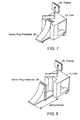
- FIG. 7shows a gantry ring positioning unit in a parked mode
- FIG. 8shows the gantry ring positioning unit in a fully extended lateral position
- FIG. 9shows the gantry ring positioning unit in a fully extended vertical position
- FIG. 10shows the gantry ring positioning unit in a fully extended tilt position
- FIG. 11shows the gantry ring and positioning unit in fully extended lateral, vertical, and tilt positions
- FIG. 12illustrates an x-ray imaging apparatus having a vertical-axis gantry for imaging a standing or sitting patient.
- FIG. 1is a schematic diagram showing an x-ray scanning system 10 in accordance with one embodiment of the invention.
- the x-ray scanning system 10includes a gantry 11 secured to a support structure, which could be a mobile or stationary cart, a patient table, a wall, a floor, or a ceiling.
- the gantry 11is secured to a mobile cart 12 in a cantilevered fashion via a ring positioning unit 20 .
- the ring positioning unit 20translates and/or tilts the gantry 11 with respect to the support structure to position the gantry 11 in any number of imaging positions and orientations.
- the mobile cart 12 of FIG. 1can optionally include a power supply, an x-ray power generator, and a computer system for controlling operation of the x-ray scanning device and for performing image processing, storage of x-ray images, or other data processing functions.
- the computer systemcontrols the positioning unit 20 to enable the gantry 11 to be quickly moved to a particular user-defined position and orientation.
- the computerpreferably has a memory that is capable of storing positioning information relating to particular gantry positions and/or orientations. This stored positioning information can be used to automatically move the gantry to a pre-defined configuration upon demand.
- the mobile cart 12preferably also includes a display system 60 , such as a flat panel display, for displaying images obtained by the x-ray scanner.
- the displaycan also include a user interface function, such as a touch-screen controller, that enables a user to interact with and control the functions of the scanning system.
- a user-controlled pendant or foot pedalcan control the functions of the scanning system.
- one or more fixed unitscan also perform any of the functions of the mobile cart 12 .
- the x-ray scanning system of the inventioncan be used to obtain two-dimensional x-ray images of an object, such as a patient, in multiple projection planes.
- the gantry 11is a generally circular, or “O-shaped,” housing having a central opening into which an object being imaged is placed.
- the gantry 11contains an x-ray source 13 (such as a rotating anode pulsed x-ray source) that projects a beam of x-ray radiation 15 into the central opening of the gantry, through the object being imaged, and onto a detector array 14 (such as a flat panel digital detector array) located on the opposite side of the gantry.
- the x-rays received at the detector 14can then be used to produce a two-dimensional image of the object using well-known techniques.
- the x-ray source 13is able to rotate around the interior of the gantry 11 in a continuous or step-wise manner so that the x-ray beam can be projected through the object, and through a common isocenter, at various angles over a partial or full 360 degree rotation.
- the detector arrayis also rotated around the interior of the gantry, in coordination with the rotation of the x-ray source, so that for each projection angle of the x-ray source, the detector array is positioned opposite the x-ray source on the gantry.
- the apparatusis thus able to obtain two-dimensional x-ray images of the targeted object in any projection plane over a partial or full 360 degree rotation.
- the x-ray system of the inventioncan be operated in a static or in a multi-planar mode.
- a static modea user selects a desired imaging plane in the target object, and the x-ray source and detector are rotated to the appropriate angle within the gantry.
- the x-ray source and detectorare at the top and bottom of the gantry, respectively, for acquisition of an anterior-posterior (AP) type patient image.
- APanterior-posterior
- the gantryitself can be moved by positioning or tilting the gantry relative to the target object using the gantry positioning unit 20 , as shown in FIG. 11 .
- the x-ray scannercan acquire and display a single x-ray image of the object, or can obtain multiple images of the object, and continuously update the display with the most recent image.
- the x-ray scannerobtains multiple object images in quick succession, and displays these images in real time (e.g. 30 frames per second) in a “cinematic” mode.
- the x-ray source and detectorcan be rotated to another angle within the gantry. As shown in FIG. 2B , for example, the source and detector rotate 90 degrees in a clockwise direction for obtaining object images in a lateral plane. Alternatively or in addition, translating or tilting the entire gantry to a second position can change the imaging plane.
- the x-ray scannerobtains a series of images from multiple projection planes in rapid succession.
- the imaging systemadvantageously permits quasi-simultaneous multi-planar imaging using a single radiation source.
- the x-ray source 13 and detector 14are initially positioned at the top and bottom of the gantry respectively and acquire a first x-ray image of the target object, which in this case is an anterior-posterior (AP) view of a patient's spine.
- the source and detectorthen rotate 90 degrees clockwise within the fixed gantry to obtain a second x-ray image shown in FIG. 2B , which is a lateral view of the spine.
- APanterior-posterior
- bi-planar AP/lateral imagesare obtained quasi-simultaneously, as there is no appreciable delay between the acquisition of the two images, other than the time it takes for the source to rotate between projection angles on the gantry.
- Additional AP/lateral imagescan be obtained and continuously updated by alternatively rotating the source and detector between two projection angles, such as the two perpendicular projections shown FIGS. 2A and 2B .
- quasi-simultaneous multi-planar imagesare obtained and updated in real time by continuously rotating the source and detector over a full 360 degree rotation, obtaining images at desired rotational increments. As shown in FIGS.
- bi-planar imagesincluding two AP images, and two lateral images, can be obtained in quick succession during a single 360 degree rotation of the source and detector. These images can be displayed individually, sequentially, side-by-side, or in any desired manner.
- FIG. 3A further illustration of the quasi-simultaneous multi-planar imaging of the invention is shown in FIG. 3 .
- a rotatable detector arrayis shown capturing quasi-simultaneous x-ray images of ten incremental projection planes over a full 360 degree rotation. These images are captured continuously, or in a step wise fashion. They can be displayed individually, side-by-side, sequentially in a cinematic mode, or in any desired manner.
- the x-ray source 13 and detector array 14can be secured to a C-shaped motorized rotor assembly 33 .
- the rigid rotor assemblymaintains the source and detector opposed to one another while the entire rotor assembly rotates inside the gantry.
- the rotor assembly 33also includes a motor 31 and drive wheel 32 for driving the rotor assembly around the interior of the gantry.
- the interior side walls of the gantryinclude curved rails 27 extending in a continuous loop around the interior of the gantry.
- the drive wheel 32 of the rotor assembly 33contacts the curved rail 27 of the gantry, and uses the rail to drive the rotor assembly around the interior of the gantry.
- a rotary incremental encodercan be used to precisely measure the angular position of the rotor assembly within the gantry.
- the incremental encodercan be driven by a friction wheel that rolls on a concentric rail located within the sidewall of the gantry.
- the rotor assembly 33also includes bearings 29 , which mate with the curved rails 27 of the gantry to help guide the rotor assembly 33 as it rotates inside the gantry.
- the interior of the gantry ring 11can include a slip ring 102 that maintains electrical contact with the rotor assembly 33 to provide the power (e.g., from external power source 101 ) needed to operate the x-ray source/detector and to rotate the entire assembly within the gantry frame.
- the slip ringcan also be used to transmit control signals to the rotor, and x-ray imaging data from the detector to a separate processing unit located outside the gantry, such as the mobile cart 12 of FIG. 1 . Any or all of the functions of the slip ring could be performed by other means, such as the cable management system described below.
- the rotor assembly of the preferred embodimentis a C-shaped rotor, it will be understood that other rotor configurations, such as O-shaped rotors, could also be employed.
- the x-ray source and detectorcould rotate independently of one another using separate mechanized systems.
- the x-ray source alonecan rotate, with multiple detector arrays located at fixed positions around the interior of the gantry.
- the detector array 14 shown in FIG. 4comprises a two-dimensional flat panel solid-state detector array. It will be understood, however, that various detectors and detector arrays can be used in this invention, including any detector configurations used in typical diagnostic fan-beam or cone-beam imaging systems, such as C-arm fluoroscopes.
- a preferred detectoris a two-dimensional thin-film transistor x-ray detector using scintillator amorphous-silicon technology.
- the detector 14can be translated to, and acquire imaging data at, two or more positions along a line or arc opposite the x-ray source 13 , such as via a motorized detector rail and bearing system. Examples of such detector systems are described in commonly owned U.S. Provisional Application 60/366,062, filed Mar. 19, 2002, the entire teachings of which are incorporated herein by reference.
- FIGS. 6A-Eillustrate another embodiment of an x-ray imaging apparatus having a cable management system for rotating an x-ray source and detector array 360° around the interior of the gantry ring.
- the power for the x-ray source/detector system, as well as for rotating the x-ray source/detector within the gantryis provided (at least in part) by a cable harness 36 containing one or more cables.
- the cable harness 36can also be used to transmit signals and data between the x-ray source/detector and an external processing unit.
- the cable harness 36is preferably housed in a flexible, linked cable carrier 37 .
- One end of the carrier 37is fixed to a stationary object, such as the gantry 11 or the cart.
- the other end of the carrier 37is attached to the motorized rotor assembly 33 which contains the x-ray source 13 and detector 14 .
- the rotor 33then rotates in a clockwise direction around the interior of the gantry, as illustrated in FIG. 6B (90° rotation), FIG.
- FIG. 6Ethe rotor 33 has made a full 360° rotation around the interior of the gantry 11 , and the rotor is again at the initial position with the x-ray source 13 at the bottom of the gantry, and the detector 14 at the top of the gantry.
- the cable carrier 37remains connected to both the rotor 33 and gantry 11 , and has sufficient length and flexibility to permit the rotor 33 to easily rotate at least 360° from the start position.
- this processcan repeat itself indefinitely with the rotor making full 360° rotations in alternatively clockwise and counterclockwise directions.
- the ring positioning unit 20preferably enables the gantry 11 to translate and/or tilt with respect to the support structure.
- FIG. 7shows a gantry ring positioning unit in a parked mode.
- FIG. 8shows the translational motion of the positioning unit in a lateral direction relative to the cart.
- FIG. 9shows translational movement of the positioning unit in a vertical direction relative to the cart.
- FIG. 10shows the tilting motion of the positioning unit relative to the cart.
- FIG. 11the entire gantry assembly is illustrated in fully extended lateral, vertical, and tilt positions. The ability of the gantry to translate and tilt in multiple directions allows for the acquisition of x-ray images in any desired projection plane, without having to continuously reposition the patient or the system.
- a control systemcan automatically move the gantry to a desired position or orientation, including to user-defined positions and orientations stored in computer memory, for x-ray imaging procedures.
- X-ray scanning devices with cantilevered, multiple-degree-of-freedom movable gantriesare described in commonly owned U.S. Provisional Applications 60/388,063, filed Jun. 11, 2002, and 60/405,098, filed Aug. 21, 2002, the entire teachings of which are incorporated herein by reference.
- the central axis of the gantryis oriented essentially horizontally, so that an object being imaged, such as a patient, lies lengthwise in the imaging area.
- the gantrymay be aligned so that its central axis extends at virtually any angle relative to the patient or object being imaged.
- the central axis of the gantrycan be aligned essentially vertically, as shown in FIG. 12 .
- the central opening of the gantryis concentric with the “cylinder” formed by the torso of a standing or sitting human. The entire imaging procedure can thus be performed while the patient remains in a standing or sitting position.
- the vertical axis gantrymay be useful for imaging other objects in which it is convenient to image the object while it is aligned in a standing or vertical orientation.
- An imaging device of the present inventioncould also comprise a substantially O-shaped gantry that includes a segment that at least partially detaches from the gantry ring to provide an opening or “break” in the gantry ring through which the object to be imaged may enter and exit the central imaging area of the gantry ring in a radial direction.
- An advantage of this type of deviceis the ability to manipulate the x-ray gantry around the target object, such as a patient, and then close the gantry around the object, causing minimal disruption to the object, in order to perform x-ray imaging. Examples of “breakable” gantry devices for x-ray imaging are described in commonly-owned U.S.
- MRImagnetic resonance imaging
- PETpositron emission tomography
- SPECTsingle photon emission computed tomography
- ultrasound imagingand photographic imaging.
Landscapes
- Health & Medical Sciences (AREA)
- Life Sciences & Earth Sciences (AREA)
- Medical Informatics (AREA)
- Engineering & Computer Science (AREA)
- Radiology & Medical Imaging (AREA)
- Molecular Biology (AREA)
- Biophysics (AREA)
- Nuclear Medicine, Radiotherapy & Molecular Imaging (AREA)
- Optics & Photonics (AREA)
- Pathology (AREA)
- Physics & Mathematics (AREA)
- Biomedical Technology (AREA)
- Heart & Thoracic Surgery (AREA)
- High Energy & Nuclear Physics (AREA)
- Surgery (AREA)
- Animal Behavior & Ethology (AREA)
- General Health & Medical Sciences (AREA)
- Public Health (AREA)
- Veterinary Medicine (AREA)
- Apparatus For Radiation Diagnosis (AREA)
- Analysing Materials By The Use Of Radiation (AREA)
Abstract
Description
Claims (27)
Priority Applications (1)
| Application Number | Priority Date | Filing Date | Title |
|---|---|---|---|
| US11/639,362US8746973B2 (en) | 2002-03-13 | 2006-12-14 | Systems and methods for quasi-simultaneous multi-planar x-ray imaging |
Applications Claiming Priority (3)
| Application Number | Priority Date | Filing Date | Title |
|---|---|---|---|
| US36390202P | 2002-03-13 | 2002-03-13 | |
| US10/389,268US7188998B2 (en) | 2002-03-13 | 2003-03-13 | Systems and methods for quasi-simultaneous multi-planar x-ray imaging |
| US11/639,362US8746973B2 (en) | 2002-03-13 | 2006-12-14 | Systems and methods for quasi-simultaneous multi-planar x-ray imaging |
Related Parent Applications (1)
| Application Number | Title | Priority Date | Filing Date |
|---|---|---|---|
| US10/389,268ContinuationUS7188998B2 (en) | 2002-03-13 | 2003-03-13 | Systems and methods for quasi-simultaneous multi-planar x-ray imaging |
Publications (2)
| Publication Number | Publication Date |
|---|---|
| US20080013691A1 US20080013691A1 (en) | 2008-01-17 |
| US8746973B2true US8746973B2 (en) | 2014-06-10 |
Family
ID=28041829
Family Applications (2)
| Application Number | Title | Priority Date | Filing Date |
|---|---|---|---|
| US10/389,268Expired - LifetimeUS7188998B2 (en) | 2002-03-13 | 2003-03-13 | Systems and methods for quasi-simultaneous multi-planar x-ray imaging |
| US11/639,362Expired - LifetimeUS8746973B2 (en) | 2002-03-13 | 2006-12-14 | Systems and methods for quasi-simultaneous multi-planar x-ray imaging |
Family Applications Before (1)
| Application Number | Title | Priority Date | Filing Date |
|---|---|---|---|
| US10/389,268Expired - LifetimeUS7188998B2 (en) | 2002-03-13 | 2003-03-13 | Systems and methods for quasi-simultaneous multi-planar x-ray imaging |
Country Status (8)
| Country | Link |
|---|---|
| US (2) | US7188998B2 (en) |
| EP (1) | EP1482837B1 (en) |
| JP (2) | JP2005519688A (en) |
| CN (1) | CN100398066C (en) |
| AT (1) | ATE304320T1 (en) |
| AU (1) | AU2003225836A1 (en) |
| DE (1) | DE60301619T2 (en) |
| WO (1) | WO2003077763A2 (en) |
Cited By (13)
| Publication number | Priority date | Publication date | Assignee | Title |
|---|---|---|---|---|
| US20120256099A1 (en)* | 2011-04-07 | 2012-10-11 | Mobius Imaging, Llc | Mobile x-ray imaging system |
| US20160063740A1 (en)* | 2014-08-28 | 2016-03-03 | Shimadzu Corporation | Image processing apparatus, radiation tomography apparatus, and method of performing image processing |
| US9820708B2 (en) | 2015-03-30 | 2017-11-21 | Medtronic Navigation, Inc. | Apparatus and method for mechanically providing power to a generator on a continuous rotatable rotor of an X-ray scanner |
| US9883843B2 (en) | 2015-03-19 | 2018-02-06 | Medtronic Navigation, Inc. | Apparatus and method of counterbalancing axes and maintaining a user selected position of a X-Ray scanner gantry |
| WO2020206440A1 (en)* | 2019-04-05 | 2020-10-08 | Arizona Board Of Regents On Behalf Of The University Of Arizona | Multiplexed computed tomography x-ray imaging |
| US10799194B2 (en) | 2010-03-12 | 2020-10-13 | Mobius Imaging, Llc | Caster system for mobile apparatus |
| US10835190B2 (en) | 2013-03-15 | 2020-11-17 | Mobius Imaging, Llc | Mobile X-ray imaging system |
| US10980692B2 (en) | 2016-08-29 | 2021-04-20 | Mobius Imaging, Llc | Table system for medical imaging |
| US10987068B2 (en) | 2012-06-14 | 2021-04-27 | Mobius Imaging Llc | Multi-directional x-ray imaging system |
| US11197643B2 (en) | 2018-03-16 | 2021-12-14 | Mobius Imaging, Llc | Medical x-ray imaging systems and methods |
| WO2022000055A1 (en)* | 2020-07-02 | 2022-01-06 | Vmi Tecnologias Ltda | X-ray apparatus with static tube holder/orthogonal bucky with isocentrically rotating articulated arm |
| US11944469B2 (en) | 2010-03-12 | 2024-04-02 | Mobius Imaging Llc | Caster system for mobile apparatus |
| US20240245371A1 (en)* | 2023-01-19 | 2024-07-25 | Medtronic Navigation, Inc. | Counterbalanced imaging device |
Families Citing this family (235)
| Publication number | Priority date | Publication date | Assignee | Title |
|---|---|---|---|---|
| US6477400B1 (en) | 1998-08-20 | 2002-11-05 | Sofamor Danek Holdings, Inc. | Fluoroscopic image guided orthopaedic surgery system with intraoperative registration |
| US7188998B2 (en) | 2002-03-13 | 2007-03-13 | Breakaway Imaging, Llc | Systems and methods for quasi-simultaneous multi-planar x-ray imaging |
| AU2003224711A1 (en) | 2002-03-19 | 2003-10-08 | Breakaway Imaging, Llc | Computer tomograph with a detector following the movement of a pivotable x-ray source |
| AU2003245439A1 (en) | 2002-06-11 | 2003-12-22 | Breakaway Imaging, Llc | Cantilevered gantry apparatus for x-ray imaging |
| US7106825B2 (en) | 2002-08-21 | 2006-09-12 | Breakaway Imaging, Llc | Apparatus and method for reconstruction of volumetric images in a divergent scanning computed tomography system |
| ATE471110T1 (en)* | 2002-08-21 | 2010-07-15 | Breakaway Imaging Llc | SCAFFOLD POSITIONING DEVICE FOR X-RAY EQUIPMENT |
| WO2005013828A1 (en)* | 2003-08-07 | 2005-02-17 | Xoran Technologies, Inc. | Intraoperative imaging system |
| US7611281B2 (en)* | 2004-01-08 | 2009-11-03 | Xoran Technologies, Inc. | Reconfigurable computer tomography scanner |
| US7567834B2 (en) | 2004-05-03 | 2009-07-28 | Medtronic Navigation, Inc. | Method and apparatus for implantation between two vertebral bodies |
| FR2884331B1 (en)* | 2005-04-07 | 2007-11-02 | Gen Electric | MEDICAL SYSTEM COMPRISING A DEVICE FOR CONNECTING A MOBILE CONTROL UNIT TO A MEDICAL EXAMINATION TABLE |
| US20070041613A1 (en)* | 2005-05-11 | 2007-02-22 | Luc Perron | Database of target objects suitable for use in screening receptacles or people and method and apparatus for generating same |
| EP1886257A1 (en)* | 2005-05-11 | 2008-02-13 | Optosecurity Inc. | Method and system for screening luggage items, cargo containers or persons |
| US7991242B2 (en) | 2005-05-11 | 2011-08-02 | Optosecurity Inc. | Apparatus, method and system for screening receptacles and persons, having image distortion correction functionality |
| JP2009502293A (en)* | 2005-07-25 | 2009-01-29 | コーニンクレッカ フィリップス エレクトロニクス エヌ ヴィ | System and method for providing lateral and anterior x-ray images of a patient |
| JP4929448B2 (en)* | 2005-07-29 | 2012-05-09 | 財団法人ヒューマンサイエンス振興財団 | Tomography equipment |
| US7742796B2 (en)* | 2005-10-25 | 2010-06-22 | General Electric Company | Breast immobilization device and method of imaging the breast |
| DE112007000399B4 (en)* | 2006-02-14 | 2019-02-21 | Xoran Technologies, Inc. | Self-shielding CT scanner |
| CA2584683A1 (en)* | 2006-04-20 | 2007-10-20 | Optosecurity Inc. | Apparatus, method and system for screening receptacles and persons |
| US7899232B2 (en)* | 2006-05-11 | 2011-03-01 | Optosecurity Inc. | Method and apparatus for providing threat image projection (TIP) in a luggage screening system, and luggage screening system implementing same |
| US8494210B2 (en)* | 2007-03-30 | 2013-07-23 | Optosecurity Inc. | User interface for use in security screening providing image enhancement capabilities and apparatus for implementing same |
| US7825383B2 (en)* | 2006-09-21 | 2010-11-02 | Siemens Medical Solutions Usa, Inc. | Mobile camera for organ targeted imaging |
| US7723674B2 (en)* | 2006-09-21 | 2010-05-25 | Siemens Medical Solutions Usa, Inc. | Attenuation correction for SPECT imaging using non-classical orbits of many small gamma cameras |
| DE102006055134A1 (en)* | 2006-11-22 | 2008-05-29 | Siemens Ag | Urological X-ray workstation for implementing percutaneous meshing, has X-ray source and X-ray receiver, which are supported at holder of carrier, so that source and receiver are positioned in plane at different positions in circular path |
| US8727618B2 (en)* | 2006-11-22 | 2014-05-20 | Siemens Aktiengesellschaft | Robotic device and method for trauma patient diagnosis and therapy |
| US7607832B2 (en)* | 2006-11-23 | 2009-10-27 | General Electric Company | Apparatus for medical imaging |
| US20080140180A1 (en)* | 2006-12-07 | 2008-06-12 | Medtronic Vascular, Inc. | Vascular Position Locating Apparatus and Method |
| US20080147173A1 (en)* | 2006-12-18 | 2008-06-19 | Medtronic Vascular, Inc. | Prosthesis Deployment Apparatus and Methods |
| US8473030B2 (en) | 2007-01-12 | 2013-06-25 | Medtronic Vascular, Inc. | Vessel position and configuration imaging apparatus and methods |
| US20080172119A1 (en)* | 2007-01-12 | 2008-07-17 | Medtronic Vascular, Inc. | Prosthesis Deployment Apparatus and Methods |
| US7434996B2 (en)* | 2007-01-19 | 2008-10-14 | General Electric Co. | Method and apparatus for a C-arm system |
| US20080188921A1 (en)* | 2007-02-02 | 2008-08-07 | Medtronic Vascular, Inc. | Prosthesis Deployment Apparatus and Methods |
| JP4228019B2 (en)* | 2007-02-16 | 2009-02-25 | 三菱重工業株式会社 | Medical equipment |
| CA2688169A1 (en)* | 2007-05-24 | 2008-11-27 | P-Cure Ltd. | Irradiation treatment apparatus and method |
| US7847275B2 (en)* | 2007-05-24 | 2010-12-07 | Pcure Ltd. | Method and apparatus for teletherapy positioning and validation |
| US20090213984A1 (en)* | 2008-02-26 | 2009-08-27 | United Technologies Corp. | Computed Tomography Systems and Related Methods Involving Post-Target Collimation |
| US7639777B2 (en)* | 2008-02-26 | 2009-12-29 | United Technologies Corp. | Computed tomography systems and related methods involving forward collimation |
| US20090225954A1 (en)* | 2008-03-06 | 2009-09-10 | United Technologies Corp. | X-Ray Collimators, and Related Systems and Methods Involving Such Collimators |
| US8238521B2 (en)* | 2008-03-06 | 2012-08-07 | United Technologies Corp. | X-ray collimators, and related systems and methods involving such collimators |
| US7876875B2 (en)* | 2008-04-09 | 2011-01-25 | United Technologies Corp. | Computed tomography systems and related methods involving multi-target inspection |
| US20090259284A1 (en)* | 2008-04-10 | 2009-10-15 | Medtronic Vascular, Inc. | Resonating Stent or Stent Element |
| US20090259296A1 (en)* | 2008-04-10 | 2009-10-15 | Medtronic Vascular, Inc. | Gate Cannulation Apparatus and Methods |
| US20090274264A1 (en)* | 2008-04-30 | 2009-11-05 | United Technologies Corp. | Computed Tomography Systems and Related Methods Involving Localized Bias |
| US7888647B2 (en)* | 2008-04-30 | 2011-02-15 | United Technologies Corp. | X-ray detector assemblies and related computed tomography systems |
| US7954996B2 (en)* | 2008-07-08 | 2011-06-07 | General Electric Company | Positioning system with tilting arm support for imaging devices |
| DE102008036015B4 (en)* | 2008-08-01 | 2011-02-24 | Siemens Aktiengesellschaft | Rotor for a gantry of a computed tomography device and computed tomography device with such a rotor |
| US9737235B2 (en)* | 2009-03-09 | 2017-08-22 | Medtronic Navigation, Inc. | System and method for image-guided navigation |
| US9226689B2 (en) | 2009-03-10 | 2016-01-05 | Medtronic Xomed, Inc. | Flexible circuit sheet |
| US9226688B2 (en) | 2009-03-10 | 2016-01-05 | Medtronic Xomed, Inc. | Flexible circuit assemblies |
| US8504139B2 (en) | 2009-03-10 | 2013-08-06 | Medtronic Xomed, Inc. | Navigating a surgical instrument |
| US8210745B2 (en)* | 2009-05-04 | 2012-07-03 | John Yorkston | Extremity imaging apparatus for cone beam computed tomography |
| US8348506B2 (en)* | 2009-05-04 | 2013-01-08 | John Yorkston | Extremity imaging apparatus for cone beam computed tomography |
| US8503745B2 (en)* | 2009-05-13 | 2013-08-06 | Medtronic Navigation, Inc. | System and method for automatic registration between an image and a subject |
| US8238631B2 (en) | 2009-05-13 | 2012-08-07 | Medtronic Navigation, Inc. | System and method for automatic registration between an image and a subject |
| US8737708B2 (en) | 2009-05-13 | 2014-05-27 | Medtronic Navigation, Inc. | System and method for automatic registration between an image and a subject |
| DE102009049074B4 (en)* | 2009-10-12 | 2011-09-01 | Siemens Aktiengesellschaft | radiation therapy device |
| US20110110570A1 (en)* | 2009-11-10 | 2011-05-12 | Avi Bar-Shalev | Apparatus and methods for generating a planar image |
| US20110122990A1 (en)* | 2009-11-24 | 2011-05-26 | Ehud Dafni | Methods apparatus assemblies and systems for implementing a ct scanner |
| US8836785B2 (en)* | 2010-03-09 | 2014-09-16 | Stephen Michael Swinford | Production and internet-viewing of high-resolution images of the commonly viewed exterior surfaces of vehicles, each with the same background view |
| US11570369B1 (en) | 2010-03-09 | 2023-01-31 | Stephen Michael Swinford | Indoor producing of high resolution images of the commonly viewed exterior surfaces of vehicles, each with the same background view |
| KR101478264B1 (en) | 2010-04-30 | 2014-12-31 | 메드트로닉 좀드 인코퍼레이티드 | Navigated malleable surgical instrument |
| US8842893B2 (en) | 2010-04-30 | 2014-09-23 | Medtronic Navigation, Inc. | Method and apparatus for image-based navigation |
| CN101869479B (en)* | 2010-06-13 | 2012-04-18 | 苏州纽迈电子科技有限公司 | Movable low-field nuclear magnetic resonance imaging system |
| KR101095518B1 (en) | 2010-06-29 | 2011-12-16 | 한국생산기술연구원 | Switchgear module, control method of switchgear module, and imaging device using the same |
| US20120022366A1 (en)* | 2010-07-21 | 2012-01-26 | Marcus Pfister | Registration of aorta to patient via two 2d images for placement of a stent |
| US8755489B2 (en) | 2010-11-11 | 2014-06-17 | P-Cure, Ltd. | Teletherapy location and dose distribution control system and method |
| KR101708262B1 (en)* | 2010-11-27 | 2017-02-20 | 아이씨알씨오, 인코포레이티드 | Computed tomography and tomosynthesis system |
| CN103282081B (en)* | 2010-12-08 | 2017-06-23 | 伊利克塔股份有限公司 | radiation therapy equipment |
| US8737567B2 (en) | 2011-01-27 | 2014-05-27 | Medtronic Navigation, Inc. | Image acquisition optimization |
| US10492868B2 (en) | 2011-01-28 | 2019-12-03 | Medtronic Navigation, Inc. | Method and apparatus for image-based navigation |
| US10617374B2 (en) | 2011-01-28 | 2020-04-14 | Medtronic Navigation, Inc. | Method and apparatus for image-based navigation |
| US9974501B2 (en) | 2011-01-28 | 2018-05-22 | Medtronic Navigation, Inc. | Method and apparatus for image-based navigation |
| US8768019B2 (en) | 2011-02-03 | 2014-07-01 | Medtronic, Inc. | Display of an acquired cine loop for procedure navigation |
| WO2012103901A1 (en)* | 2011-02-04 | 2012-08-09 | Elekta Ab (Publ) | Ct imaging apparatus and methods |
| US8562211B2 (en) | 2011-03-30 | 2013-10-22 | Medtronic Navigation, Inc. | System and method for off-center imaging |
| US9411057B2 (en) | 2011-04-01 | 2016-08-09 | Medtronic Navigation, Inc. | X-ray imaging system and method |
| US9138204B2 (en) | 2011-04-29 | 2015-09-22 | Medtronic Navigation, Inc. | Method and apparatus for calibrating and re-aligning an ultrasound image plane to a navigation tracker |
| US8811662B2 (en) | 2011-04-29 | 2014-08-19 | Medtronic Navigation, Inc. | Method and apparatus for calibrating and re-aligning an ultrasound image plane to a navigation tracker |
| KR101307266B1 (en)* | 2011-05-25 | 2013-09-11 | 한국생산기술연구원 | Gantry positioning apparatus and imaging apparatus using the same |
| US8971495B2 (en) | 2011-06-02 | 2015-03-03 | Medtronic Navigation, Inc. | Method and apparatus for power control in an image-based navigation system |
| US10849574B2 (en) | 2011-06-22 | 2020-12-01 | Medtronic Navigation, Inc. | Interventional imaging |
| US8767910B2 (en) | 2011-06-22 | 2014-07-01 | Medtronic Navigation, Inc. | Hybrid multi-row detector and flat panel imaging system |
| EP2545855B1 (en)* | 2011-07-13 | 2016-09-07 | General Electric Company | System and method of locating an X-ray imaging apparatus and corresponding X-ray imaging apparatus. |
| KR101973221B1 (en) | 2011-09-07 | 2019-04-26 | 라피스캔 시스템스, 인코포레이티드 | X-ray inspection system that integrates manifest data with imaging/detection processing |
| US9008414B2 (en) | 2011-10-04 | 2015-04-14 | Medtronic Navigation, Inc. | Method and apparatus for assisted trajectory planning |
| KR101172485B1 (en) | 2011-10-07 | 2012-08-10 | 한국생산기술연구원 | Opening and closing module, control method for the same |
| US9750486B2 (en) | 2011-10-25 | 2017-09-05 | Medtronic Navigation, Inc. | Trackable biopsy needle |
| US8948338B2 (en) | 2011-11-03 | 2015-02-03 | Medtronic Navigation, Inc. | Dynamically scanned X-ray detector panel |
| KR101254098B1 (en) | 2011-12-08 | 2013-04-12 | 한국생산기술연구원 | Shoot module rotating apparatus and image obtaining apparatus of comprising the same |
| KR101254097B1 (en) | 2011-12-08 | 2013-04-12 | 한국생산기술연구원 | Shoot module rotating apparatus and image obtaining apparatus of comprising the same |
| US8891847B2 (en) | 2012-01-23 | 2014-11-18 | Medtronic Navigation, Inc. | Automatic implant detection from image artifacts |
| EP2676627B1 (en) | 2012-04-18 | 2021-07-28 | Medtronic Navigation, Inc. | System and method for automatic registration between an image and a subject |
| KR101376834B1 (en) | 2012-04-27 | 2014-03-20 | 가천대학교 산학협력단 | a real-time motion tracking of the subject and medical imaging correction method |
| WO2014004447A1 (en)* | 2012-06-26 | 2014-01-03 | Gregerson Eugene A | Multi-plane x-ray imaging system and method |
| US9498290B2 (en) | 2012-07-19 | 2016-11-22 | MRI Interventions, Inc. | Surgical navigation devices and methods |
| JP6370297B2 (en)* | 2012-09-07 | 2018-08-08 | トロフィー | Device for partial CT imaging |
| EP2903522B1 (en) | 2012-10-08 | 2016-09-21 | Carestream Health, Inc. | Extremity imaging apparatus for cone beam computed tomography |
| US10278729B2 (en) | 2013-04-26 | 2019-05-07 | Medtronic Xomed, Inc. | Medical device and its construction |
| US20150043712A1 (en)* | 2013-08-07 | 2015-02-12 | Carestream Health, Inc. | Imaging system and method for portable stereoscopic tomography |
| CN103471999B (en)* | 2013-08-30 | 2015-11-04 | 深圳先进技术研究院 | A computerized tomography system |
| US10143860B2 (en) | 2014-01-21 | 2018-12-04 | Hitachi, Ltd. | Radiation therapy apparatus |
| KR20150088679A (en)* | 2014-01-24 | 2015-08-03 | 주식회사바텍 | Apparatus for Obtaining Computed Tomography |
| US9254108B2 (en)* | 2014-03-18 | 2016-02-09 | General Electric Company | Gantry with bore safety mechanism |
| WO2016020859A1 (en)* | 2014-08-07 | 2016-02-11 | Imaginalis S.R.L. | Radiological imaging device with improved manoeuvrability |
| US10716956B2 (en) | 2015-04-21 | 2020-07-21 | Our United Corporation | Radiotherapeutic device |
| DE102015207736B4 (en)* | 2015-04-28 | 2021-08-26 | Siemens Healthcare Gmbh | Mobile C-arm X-ray machine |
| US10898271B2 (en) | 2015-06-29 | 2021-01-26 | Medtronic Navigation, Inc. | Method and apparatus for identification of multiple navigated instruments |
| CN106693213B (en)* | 2015-07-17 | 2018-02-13 | 苏州雷泰医疗科技有限公司 | Accelerator therapy device base and accelerator therapy device |
| US10206635B2 (en)* | 2015-10-20 | 2019-02-19 | Toshiba Medical Systems Corporation | X-ray computed tomography apparatus and gantry |
| KR20170047813A (en)* | 2015-10-23 | 2017-05-08 | 삼성전자주식회사 | Computed tomography apparatus |
| USD824027S1 (en) | 2016-01-13 | 2018-07-24 | MRI Interventions, Inc. | Fins for a support column for a surgical trajectory frame |
| USD829904S1 (en) | 2016-01-13 | 2018-10-02 | MRI Interventions, Inc. | Curved bracket for surgical navigation systems |
| US10376333B2 (en) | 2016-01-14 | 2019-08-13 | MRI Interventions, Inc. | Devices for surgical navigation systems |
| US10448910B2 (en)* | 2016-02-03 | 2019-10-22 | Globus Medical, Inc. | Portable medical imaging system |
| CN116309260A (en) | 2016-02-22 | 2023-06-23 | 拉皮斯坎系统股份有限公司 | Method for evaluating average pallet size and density of goods |
| EP3488785B1 (en) | 2016-03-09 | 2024-07-03 | Medtronic Navigation, Inc. | Transformable imaging system |
| CN108882905B (en)* | 2016-03-25 | 2022-08-23 | 卡尔斯特里姆保健公司 | CBCT imaging system with curved detector |
| US11172821B2 (en) | 2016-04-28 | 2021-11-16 | Medtronic Navigation, Inc. | Navigation and local thermometry |
| US10191615B2 (en) | 2016-04-28 | 2019-01-29 | Medtronic Navigation, Inc. | Method and apparatus for image-based navigation |
| CN109152561B (en) | 2016-05-11 | 2023-04-04 | 皇家飞利浦有限公司 | Anatomically adjusted acquisition with a stationary multi-source X-ray system |
| DE102016208123B4 (en)* | 2016-05-11 | 2020-03-19 | Siemens Healthcare Gmbh | Method and system for executing a scanning movement of an imaging data acquisition unit |
| DE102016208328B4 (en)* | 2016-05-13 | 2024-07-11 | Siemens Healthineers Ag | Medical imaging device |
| US10709508B2 (en) | 2016-07-28 | 2020-07-14 | Medtronics Ps Medical, Inc. | Tracked powered drill assembly |
| US11839433B2 (en) | 2016-09-22 | 2023-12-12 | Medtronic Navigation, Inc. | System for guided procedures |
| AU2017340607B2 (en) | 2016-10-05 | 2022-10-27 | Nuvasive, Inc. | Surgical navigation system and related methods |
| DE102016220741A1 (en)* | 2016-10-21 | 2017-09-07 | Siemens Healthcare Gmbh | Medical imaging examination device |
| US10667923B2 (en) | 2016-10-31 | 2020-06-02 | Warsaw Orthopedic, Inc. | Sacro-iliac joint implant system and method |
| CN110099717B (en)* | 2016-11-15 | 2021-08-27 | 西安大医集团股份有限公司 | Therapeutic equipment |
| US11842030B2 (en) | 2017-01-31 | 2023-12-12 | Medtronic Navigation, Inc. | Method and apparatus for image-based navigation |
| US11219422B2 (en)* | 2017-03-14 | 2022-01-11 | Canon Medical Systems Corporation | Image displaying system, image processing apparatus and x-ray imaging system |
| US10888286B2 (en) | 2017-03-22 | 2021-01-12 | Carestream Health, Inc. | CBCT imaging system with curved detector and curved grid |
| US11058892B2 (en) | 2017-05-05 | 2021-07-13 | Zap Surgical Systems, Inc. | Revolving radiation collimator |
| US10463404B2 (en) | 2017-07-27 | 2019-11-05 | Warsaw Orthopedic, Inc. | Spinal implant system and method |
| CN108401421B (en) | 2017-09-06 | 2022-12-20 | 睿谱外科系统股份有限公司 | Self-shielding integrated control radiosurgery system |
| US11399784B2 (en) | 2017-09-29 | 2022-08-02 | Medtronic Navigation, Inc. | System and method for mobile imaging |
| GB2568735A (en)* | 2017-11-25 | 2019-05-29 | Adaptix Ltd | An x-ray imaging system |
| US20190175059A1 (en) | 2017-12-07 | 2019-06-13 | Medtronic Xomed, Inc. | System and Method for Assisting Visualization During a Procedure |
| US11138768B2 (en) | 2018-04-06 | 2021-10-05 | Medtronic Navigation, Inc. | System and method for artifact reduction in an image |
| CN108686309B (en)* | 2018-06-29 | 2023-04-07 | 合肥中科离子医学技术装备有限公司 | Image guide system for proton/heavy ion medical equipment system |
| DE102018211669B4 (en)* | 2018-07-12 | 2020-01-23 | Siemens Healthcare Gmbh | Omnidirectional chassis for a gantry of a computed tomography device |
| CN109200490A (en)* | 2018-11-02 | 2019-01-15 | 新瑞阳光粒子医疗装备(无锡)有限公司 | CT machine, CT system, CT system control method and medium |
| US11918297B2 (en) | 2019-01-10 | 2024-03-05 | Mazor Robotics Ltd. | System and method for registration between coordinate systems and navigation |
| US11135025B2 (en) | 2019-01-10 | 2021-10-05 | Medtronic Navigation, Inc. | System and method for registration between coordinate systems and navigation |
| US11911110B2 (en) | 2019-01-30 | 2024-02-27 | Medtronic Navigation, Inc. | System and method for registration between coordinate systems and navigation of selected members |
| US11426242B2 (en) | 2019-01-30 | 2022-08-30 | Medtronic Navigation, Inc. | System and method for registration between coordinate systems and navigation of selected members |
| CN109893134A (en)* | 2019-01-31 | 2019-06-18 | 佛山瑞加图医疗科技有限公司 | Portable mobile magnetic resonance system |
| CN109846483B (en)* | 2019-01-31 | 2025-03-18 | 佛山瑞加图医疗科技有限公司 | A separate portable mobile magnetic resonance system |
| US11065065B2 (en) | 2019-02-22 | 2021-07-20 | Warsaw Orthopedic, Inc. | Spinal implant system and methods of use |
| US11684446B2 (en) | 2019-02-27 | 2023-06-27 | Zap Surgical Systems, Inc. | Device for radiosurgical treatment of uterine fibroids |
| EP3705048B1 (en) | 2019-03-04 | 2021-04-21 | Boscherini, Duccio | A surgical table with an integrated imaging device |
| US11285022B2 (en) | 2019-04-15 | 2022-03-29 | Warsaw Orthopedic, Inc. | Spinal implant system and method |
| US11547491B2 (en) | 2019-05-02 | 2023-01-10 | Medtronic Navigation, Inc. | Oral patient tracking device and method of using the same |
| US11446094B2 (en) | 2019-05-02 | 2022-09-20 | Medtronic Navigation, Inc. | Nasal patient tracking device and method of using the same |
| CN114007511A (en)* | 2019-06-26 | 2022-02-01 | 株式会社高迎科技 | Computed tomography apparatus and method of computed tomography using multiple light sources |
| US11672607B2 (en) | 2019-08-14 | 2023-06-13 | Warsaw Orthopedic, Inc. | Systems, devices, and methods for surgical navigation with anatomical tracking |
| CA3149577A1 (en)* | 2019-08-27 | 2021-03-04 | 4DMedical Limited | Methods, systems, and apparatus for assessing an effect of a medical treatment on organ function |
| CN110441288B (en)* | 2019-08-28 | 2024-07-12 | 南京信息工程大学 | Multi-angle target plasma collecting device |
| US11399965B2 (en) | 2019-09-09 | 2022-08-02 | Warsaw Orthopedic, Inc. | Spinal implant system and methods of use |
| US11564812B2 (en) | 2019-09-09 | 2023-01-31 | Warsaw Orthopedic, Inc. | Surgical instrument and method |
| CN114761075A (en)* | 2019-09-11 | 2022-07-15 | 西安大医集团股份有限公司 | Display device applied to radiotherapy equipment, radiotherapy equipment and method |
| US11576685B2 (en) | 2019-10-25 | 2023-02-14 | Medtronic Ps Medical, Inc. | Drill guide assembly and method |
| CN110881990A (en)* | 2019-12-05 | 2020-03-17 | 赛诺威盛科技(北京)有限公司 | A CT scanning gantry and CT scanning device |
| US11890205B2 (en) | 2019-12-13 | 2024-02-06 | Warsaw Orthopedic, Inc. | Spinal implant system and methods of use |
| US11167140B2 (en) | 2020-01-24 | 2021-11-09 | Medtronic Xomed, Inc. | System and method for therapy |
| US11167127B2 (en) | 2020-01-24 | 2021-11-09 | Medtronic Xomed, Inc. | System and method for therapy |
| US11730546B2 (en) | 2020-01-24 | 2023-08-22 | Warsaw Orthopedic, Inc. | Spinal implant system and method |
| US11623086B2 (en) | 2020-01-24 | 2023-04-11 | Medtronic Xomed, Inc. | System and method for therapy |
| US11666755B2 (en) | 2020-01-24 | 2023-06-06 | Medtronic Xomed, Inc. | System and method for therapy |
| CN111166369A (en)* | 2020-03-03 | 2020-05-19 | 南京安科医疗科技有限公司 | Openable O-shaped arm structure of double-source CT (computed tomography) equipment |
| US11571261B2 (en) | 2020-04-22 | 2023-02-07 | Medtronic Navigation, Inc. | System and method for navigation |
| US20210330390A1 (en) | 2020-04-22 | 2021-10-28 | Medtronic Navigation, Inc. | System and method for navigation |
| US11857267B2 (en) | 2020-04-22 | 2024-01-02 | Medtronic Navigation, Inc. | System and method for navigation |
| US20210346093A1 (en) | 2020-05-06 | 2021-11-11 | Warsaw Orthopedic, Inc. | Spinal surgery system and methods of use |
| US11534120B2 (en)* | 2020-06-15 | 2022-12-27 | Medtronic Navigation, Inc. | Line scanner imaging device, system, and methods |
| US11364130B2 (en) | 2020-09-01 | 2022-06-21 | Warsaw Orthopedic, Inc. | Spinal implant system and method |
| US11813094B2 (en) | 2020-09-14 | 2023-11-14 | Medtronic Navigation, Inc. | System and method for imaging |
| US12023187B2 (en) | 2020-09-14 | 2024-07-02 | Medtronic Navigation, Inc. | System and method for imaging |
| US12076172B2 (en) | 2020-09-14 | 2024-09-03 | Medtronic Navigation, Inc. | System and method for imaging |
| EP4210581B1 (en) | 2020-09-14 | 2025-07-02 | Medtronic Navigation, Inc. | System and method for imaging |
| US11801149B2 (en) | 2020-10-09 | 2023-10-31 | Warsaw Orthopedic, Inc. | Surgical instrument and method |
| US12239327B2 (en) | 2020-12-23 | 2025-03-04 | Medtronic Navigation, Inc. | Powered drill assembly |
| US12245772B2 (en) | 2020-12-23 | 2025-03-11 | Medtronic Navigation, Inc. | System and method to control operation of a drill |
| EP4267029A1 (en) | 2020-12-23 | 2023-11-01 | Medtronic Navigation, Inc. | Powered drill assembly |
| JP2024506842A (en) | 2021-02-01 | 2024-02-15 | ザップ サージカル システムズ, インコーポレイテッド | Reverse planning device and method for radiotherapy |
| US11769261B2 (en) | 2021-03-18 | 2023-09-26 | Medtronic Navigation, Inc. | Imaging system |
| US11922645B2 (en) | 2021-03-18 | 2024-03-05 | Medtronic Navigation, Inc. | Imaging system |
| US11633168B2 (en)* | 2021-04-02 | 2023-04-25 | AIX Scan, Inc. | Fast 3D radiography with multiple pulsed X-ray sources by deflecting tube electron beam using electro-magnetic field |
| US20220313340A1 (en) | 2021-04-06 | 2022-10-06 | Medtronic Navigation, Inc. | Energizable instrument assembly |
| US20220313374A1 (en) | 2021-04-06 | 2022-10-06 | Medtronic Navigation, Inc. | Powered Drill Assembly |
| US11742959B2 (en) | 2021-08-25 | 2023-08-29 | Medtronic, Inc. | System and method for wireless communications |
| US12097060B2 (en) | 2022-02-01 | 2024-09-24 | Medtronic Navigation, Inc. | Long axis imaging system and method |
| CN114587399A (en)* | 2022-04-19 | 2022-06-07 | 北京航空航天大学 | Imaging device and imaging method |
| US20240071025A1 (en) | 2022-08-31 | 2024-02-29 | Mazor Robotics Ltd. | System and method for imaging |
| US20240065661A1 (en) | 2022-08-31 | 2024-02-29 | Mazor Robotics Ltd. | System and method for imaging |
| US12257092B2 (en) | 2022-10-17 | 2025-03-25 | Medtronic Navigation, Inc. | Method to superimpose rendering over spine hardware implants on images produced by Cbct scanner system |
| US20240138915A1 (en) | 2022-10-27 | 2024-05-02 | Medtronic Navigation, Inc. | Method And Apparatus For Planning Placement Of An Implant |
| US20240138914A1 (en) | 2022-10-27 | 2024-05-02 | Medtronic Navigation, Inc. | Method and apparatus for planning placement of an implant |
| WO2024089504A1 (en) | 2022-10-28 | 2024-05-02 | Medtronic, Inc. | System operable to determine a pose of an instrument |
| WO2024089503A1 (en) | 2022-10-28 | 2024-05-02 | Medtronic, Inc. | System and method for illustrating a pose of an object |
| WO2024089502A1 (en) | 2022-10-28 | 2024-05-02 | Medtronic, Inc. | System and method for illustrating a pose of an object |
| US20240197404A1 (en) | 2022-12-15 | 2024-06-20 | Medtronic Navigation, Inc. | Method and Apparatus for Imaging a Subject |
| US20240277415A1 (en) | 2023-02-21 | 2024-08-22 | Mazor Robotics Ltd. | System and method for moving a guide system |
| US20240285348A1 (en) | 2023-02-28 | 2024-08-29 | Mazor Robotics Ltd. | Automated movement of optical localizer for optimal line of sight with optical trackers |
| US20240307131A1 (en) | 2023-03-15 | 2024-09-19 | Mazor Robotics Ltd. | Systems And Methods For An Image Guided Procedure |
| US20240328784A1 (en) | 2023-03-28 | 2024-10-03 | Medtronic Navigation, Inc. | Tracking device and method of using the same |
| US12413843B2 (en) | 2023-04-07 | 2025-09-09 | Medtronic Navigation, Inc. | System and method of patient registration |
| WO2024214033A1 (en) | 2023-04-13 | 2024-10-17 | Medtronic Navigation, Inc. | Ultrasound depth calibration for improving navigational accuracy |
| WO2024215791A1 (en) | 2023-04-13 | 2024-10-17 | Medtronic, Inc. | System and method for positioning a member relative to a subject |
| WO2024214057A1 (en) | 2023-04-13 | 2024-10-17 | Medtronic Navigation, Inc. | System and method for illustrating a pose of an object |
| WO2024215790A1 (en) | 2023-04-13 | 2024-10-17 | Medtronic, Inc. | System and method for positioning a member relative to a subject |
| WO2024215866A1 (en) | 2023-04-14 | 2024-10-17 | Medtronic Navigation, Inc. | System and method for imaging and registration for navigation |
| WO2024224319A1 (en) | 2023-04-25 | 2024-10-31 | Medtronic Navigation, Inc. | Systems and methods for imaging wide film radiographs |
| WO2024224310A1 (en) | 2023-04-26 | 2024-10-31 | Medtronic Navigation, Inc. | Surgical cart with robotic arm |
| DE102023203898B4 (en)* | 2023-04-27 | 2025-01-30 | Siemens Healthineers Ag | Slip ring system for energy transmission in a rotating system, system with a rotating component and method for supplying energy to this system |
| WO2024224350A1 (en) | 2023-04-27 | 2024-10-31 | Medtronic Navigation, Inc. | System for reducing tool vibration at a variable stiffness end effector of a surgical system |
| WO2024224351A2 (en) | 2023-04-27 | 2024-10-31 | Medtronic Navigation, Inc. | System and method for reducing tool vibration at a variable stiffness end effector of a surgical system |
| WO2024238179A1 (en) | 2023-05-15 | 2024-11-21 | Medtronic Navigation, Inc. | Long image multi-field of view preview |
| WO2024254040A1 (en) | 2023-06-09 | 2024-12-12 | Medtronic Navigation, Inc. | Touch and move anatomy localization |
| WO2024257036A1 (en) | 2023-06-16 | 2024-12-19 | Medtronic Navigation, Inc. | System and method for navigation |
| WO2025022368A1 (en) | 2023-07-27 | 2025-01-30 | Medtronic Navigation, Inc. | System and method for navigation |
| WO2025027505A1 (en) | 2023-07-28 | 2025-02-06 | Medtronic Navigation, Inc. | System and method of patient registration |
| WO2025037234A1 (en) | 2023-08-15 | 2025-02-20 | Medtronic Navigation, Inc. | System and method for mobile imaging |
| WO2025046576A1 (en) | 2023-08-31 | 2025-03-06 | Mazor Robotics Ltd. | System and method for navigation |
| WO2025088433A1 (en) | 2023-10-26 | 2025-05-01 | Medtronic Navigation, Inc. | System and method for navigation |
| WO2025088617A1 (en) | 2023-10-27 | 2025-05-01 | Mazor Robotics Ltd. | Path planning with collision avoidance |
| WO2025088575A1 (en) | 2023-10-27 | 2025-05-01 | Medtronic Navigation, Inc. | System and method for navigation |
| WO2025088616A1 (en) | 2023-10-27 | 2025-05-01 | Mazor Robotics Ltd. | Method and apparatus for procedure navigation |
| WO2025088551A1 (en) | 2023-10-27 | 2025-05-01 | Medtronic Navigation, Inc. | System and method for navigation |
| WO2025114870A1 (en) | 2023-11-30 | 2025-06-05 | Medtronic Navigation, Inc. | System for navigation |
| CN117679665B (en)* | 2023-12-05 | 2024-12-17 | 中国科学院近代物理研究所 | Multi-angle shared rotary radiotherapy head system and treatment terminal |
| WO2025158388A1 (en) | 2024-01-25 | 2025-07-31 | Medtronic Navigation, Inc. | System and method for determining a status of a tracking device |
| WO2025158394A1 (en) | 2024-01-26 | 2025-07-31 | Medtronic Navigation, Inc. | System and method for imaging |
| WO2025158335A1 (en) | 2024-01-26 | 2025-07-31 | Medtronic Navigation, Inc. | Configurable reference frame device and method of using the same |
| WO2025191487A1 (en) | 2024-03-12 | 2025-09-18 | Medtronic Navigation, Inc. | System for tracking of an instrument |
| WO2025196750A1 (en) | 2024-03-18 | 2025-09-25 | Mazor Robotics Ltd. | System and method to image data |
| WO2025203020A1 (en) | 2024-03-26 | 2025-10-02 | Mazor Robotics Ltd. | System and method to generate image visualization |
Citations (127)
| Publication number | Priority date | Publication date | Assignee | Title |
|---|---|---|---|---|
| US2818510A (en) | 1953-07-23 | 1957-12-31 | Philips Corp | Diagnostic x-ray device |
| US3549885A (en) | 1967-07-10 | 1970-12-22 | Saab Ab | Apparatus for x-raying on two mutually perpendicular axes with a pair of x-ray sources |
| US3617749A (en) | 1970-01-12 | 1971-11-02 | Philips Corp | Column support for x-ray apparatus |
| FR2304321B1 (en) | 1975-03-20 | 1979-08-31 | Emi Ltd | |
| US4200799A (en) | 1976-07-15 | 1980-04-29 | Tokyo Shibaura Electric Co., Ltd. | Tomographing device |
| GB2088670A (en) | 1980-11-26 | 1982-06-09 | Philips Nv | Radiation absorption distribution measurement in a part section of a body |
| US4352986A (en) | 1979-08-08 | 1982-10-05 | Siemens Aktiengesellschaft | Tomographic apparatus for the production of transverse layer images |
| US4355409A (en) | 1979-08-31 | 1982-10-19 | Kurt Amplatz | Scanning x-ray system |
| US4442489A (en) | 1979-06-16 | 1984-04-10 | U.S. Philips Corporation | Device for computed tomography |
| US4481656A (en) | 1981-05-11 | 1984-11-06 | U.S. Philips Corporation | Medical apparatus |
| US4636952A (en) | 1984-12-03 | 1987-01-13 | General Electric Company | Method and apparatus for back projection image reconstruction using virtual equi-spaced detector array |
| US4741015A (en)* | 1986-12-05 | 1988-04-26 | B. C. Medical Compagnie Limitee | Universal X-ray unit |
| US4803714A (en) | 1983-09-13 | 1989-02-07 | B. V. Optische Industrie "De Oude Delft" | Method for forming a radiogram using slit-scanning radiographic techniques |
| US4810881A (en) | 1986-04-30 | 1989-03-07 | Thomson-Csf | Panel for X-ray photography and method of manufacture |
| US4817121A (en) | 1986-09-24 | 1989-03-28 | Hitachi Medical Corp. | Apparatus for checking baggage with x-rays |
| US4829252A (en) | 1987-10-28 | 1989-05-09 | The Regents Of The University Of California | MRI system with open access to patient image volume |
| US4853946A (en) | 1986-11-14 | 1989-08-01 | Picker International, Inc. | Diagonostic service system for CT scanners |
| US4875228A (en) | 1988-07-12 | 1989-10-17 | Davru Manufacturing Ltd. | X-ray gantry |
| US4884293A (en) | 1988-01-19 | 1989-11-28 | Kabushiki Kaisha Toshiba | X-ray photographing apparatus |
| US4935949A (en)* | 1986-01-31 | 1990-06-19 | Yokogawa Medical Systems, Limited | Gantry for computerized tomography |
| US4955046A (en) | 1989-04-17 | 1990-09-04 | Siczek Aldona A | C-arm for X-ray diagnostic examination |
| JPH02228946A (en) | 1989-03-02 | 1990-09-11 | Toshiba Corp | X-ray CT scanner device |
| US4977585A (en) | 1989-04-05 | 1990-12-11 | Imatron, Inc. | Self shielded computerized tomographic scanner |
| US4982415A (en) | 1988-06-03 | 1991-01-01 | Kabushiki Kaisha Toshiba | X-ray CT scanner apparatus |
| US4987585A (en) | 1989-04-04 | 1991-01-22 | General Electric Company | X-ray positioner for multi-axis profiling |
| US5014293A (en)* | 1989-10-04 | 1991-05-07 | Imatron, Inc. | Computerized tomographic x-ray scanner system and gantry assembly |
| US5014292A (en) | 1990-01-29 | 1991-05-07 | Siczek Bernard W | Tiltable x-ray table integrated with carriage for x-ray source and receptor |
| US5023899A (en) | 1987-06-18 | 1991-06-11 | Ohlson Carl Eric | Method and arrangement for X-ray photography or the like |
| US5032990A (en) | 1989-05-30 | 1991-07-16 | General Electric Company | Translate rotate scanning method for x-ray imaging |
| USD323386S (en) | 1988-01-19 | 1992-01-21 | Adac Laboratories | Gantry for a medical camera |
| US5084908A (en) | 1990-02-07 | 1992-01-28 | Incubation Industries | Tomographic system |
| EP0471455A2 (en) | 1990-08-14 | 1992-02-19 | Picker International, Inc. | Imaging apparatus and methods |
| US5095501A (en) | 1989-12-06 | 1992-03-10 | Kabushiki Kaisha Toshiba | X-ray image-pickup apparatus |
| US5097497A (en) | 1991-03-01 | 1992-03-17 | Picker International, Inc. | Deployable CT medical system |
| US5159622A (en) | 1989-11-17 | 1992-10-27 | Kabushiki Kaisha Toshiba | X-ray fluoroscopic imaging apparatus with extended imaging set up range |
| US5164973A (en) | 1990-01-05 | 1992-11-17 | Hitachi Medical Corporation | Projection detecting apparatus for computer tomography |
| US5187659A (en) | 1990-09-04 | 1993-02-16 | General Electric Company | Cone beam scanning trajectories for three-dimensional computerized tomography data acquisition where object is larger than the field of view |
| EP0564292A2 (en) | 1992-04-03 | 1993-10-06 | Picker International, Inc. | Ring tube CT scanner |
| US5265610A (en) | 1991-09-03 | 1993-11-30 | General Electric Company | Multi-planar X-ray fluoroscopy system using radiofrequency fields |
| US5287274A (en) | 1989-03-20 | 1994-02-15 | General Electric Cgr Sa | Method for acquisition of radiological data in multiple orthogonal orientations using a 2D detector relating to a body irradiated with x-rays and for reconstruction of structures corresponding to said body using an algebraic algorithm |
| USD345606S (en) | 1990-11-21 | 1994-03-29 | Picker International, Inc. | Medical gamma camera gantry |
| US5319693A (en) | 1992-12-30 | 1994-06-07 | General Electric Company | Three dimensional computerized tomography scanning configuration for imaging large objects with smaller area detectors |
| US5390112A (en) | 1993-10-04 | 1995-02-14 | General Electric Company | Three-dimensional computerized tomography scanning method and system for imaging large objects with smaller area detectors |
| US5448608A (en) | 1994-02-08 | 1995-09-05 | Analogic Corporation | Tomographic scanner having center of rotation for all physics |
| US5448607A (en) | 1994-02-08 | 1995-09-05 | Analogic Corporation | X-ray tomography system with gantry pivot and translation control |
| US5452337A (en) | 1992-04-01 | 1995-09-19 | Sony Corporation | Radiation diagnostic system |
| US5499415A (en) | 1994-02-08 | 1996-03-19 | Analogic Corporation | Stabilized, cantilevered, patient trauma table system |
| US5515416A (en) | 1995-05-30 | 1996-05-07 | Siczek; Bernard W. | Bi-plane imaging device |
| CN1032188C (en) | 1986-01-31 | 1996-07-03 | 菲利浦光灯制造公司 | Mobile X-ray image intensifier |
| US5583909A (en) | 1994-12-20 | 1996-12-10 | Oec Medical Systems, Inc. | C-arm mounting structure for mobile X-ray imaging system |
| US5592523A (en) | 1994-12-06 | 1997-01-07 | Picker International, Inc. | Two dimensional detector array for CT scanners |
| US5598453A (en)* | 1994-08-30 | 1997-01-28 | Hitachi Medical Corporation | Method for X-ray fluoroscopy or radiography, and X-ray apparatus |
| DE19535583A1 (en) | 1995-09-25 | 1997-03-27 | Siemens Ag | X=ray diagnostic appts. with positioning aid |
| US5625660A (en) | 1995-06-30 | 1997-04-29 | Picker International, Inc. | Image reconstruction from helical partial cone-beam data |
| US5625662A (en) | 1995-11-20 | 1997-04-29 | General Electric Company | Modulating x-ray tube current in a CT system |
| US5638419A (en) | 1995-02-16 | 1997-06-10 | Siemens Aktiengesellschaft | Spiral-helical scan computed tomography apparatus |
| US5661772A (en) | 1996-04-01 | 1997-08-26 | Siemens Aktiengesellschaft | X-ray diagnostics apparatus capable of producing CT images and fluoroscopic images |
| US5668846A (en) | 1996-10-18 | 1997-09-16 | General Electric Company | Methods and apparatus for scanning an object and displaying an image in a computed tomography system |
| EP0810005A2 (en) | 1993-06-09 | 1997-12-03 | Wisconsin Alumni Research Foundation | Radiation therapy system |
| US5740222A (en) | 1993-11-26 | 1998-04-14 | Kabushiki Kaisha Toshiba | Radiation computed tomography apparatus |
| US5740224A (en) | 1994-09-27 | 1998-04-14 | University Of Delaware | Cone beam synthetic arrays in three-dimensional computerized tomography |
| US5745545A (en) | 1996-08-16 | 1998-04-28 | Siemens Medical Systems, Inc. | Alignment system and method for intra-operative radiation therapy |
| US5784428A (en) | 1996-07-24 | 1998-07-21 | Siemens Aktiengesellschaft | X-ray computed tomography apparatus having a gantry frame with rollers for axially and radially guiding the gantry |
| US5802138A (en) | 1996-02-29 | 1998-09-01 | Commissariat A L'energie Atomique | Multisection imaging device |
| US5912943A (en) | 1997-11-26 | 1999-06-15 | Picker International, Inc. | Cooling system for a sealed housing positioned in a sterile environment |
| DE19800946A1 (en) | 1998-01-13 | 1999-07-22 | Siemens Ag | Volume computer tomography system |
| JP2000070255A (en) | 1998-09-01 | 2000-03-07 | Siemens Ag | X-ray diagnostic equipment |
| US6041097A (en) | 1998-04-06 | 2000-03-21 | Picker International, Inc. | Method and apparatus for acquiring volumetric image data using flat panel matrix image receptor |
| JP2000116641A (en) | 1998-10-16 | 2000-04-25 | Toshiba Corp | X-ray CT system |
| JP2000197627A (en) | 1999-01-05 | 2000-07-18 | Hitachi Medical Corp | X-ray ct device |
| JP2000201920A (en) | 1999-01-19 | 2000-07-25 | Fuji Photo Film Co Ltd | Photographed image data acquiring method and photographed image data acquiring device |
| US6113264A (en) | 1997-06-04 | 2000-09-05 | Kabushiki Kaisha Toshiba | X-ray diagnostic apparatus with C-shaped arms |
| US6128365A (en) | 1998-02-11 | 2000-10-03 | Analogic Corporation | Apparatus and method for combining related objects in computed tomography data |
| US6130930A (en) | 1999-03-22 | 2000-10-10 | Siemens Corporate Research, Inc. | Exact region of interest cone beam imaging without circle scans |
| US6147352A (en) | 1998-02-23 | 2000-11-14 | Digirad Corporation | Low profile open ring single photon emission computed tomographic imager |
| JP2000312674A (en) | 1999-04-30 | 2000-11-14 | Hitachi Medical Corp | X-ray radiographing device |
| US6169780B1 (en) | 1997-09-30 | 2001-01-02 | J. Morita Manufacturing Corp. | X-ray apparatus with improved patient access |
| DE19928738A1 (en) | 1999-06-23 | 2001-01-04 | Siemens Ag | Positioning of computer tomography device |
| DE19927953A1 (en) | 1999-06-18 | 2001-01-11 | Siemens Ag | X=ray diagnostic apparatus |
| JP2001037747A (en) | 1999-07-27 | 2001-02-13 | Toshiba Corp | X-ray diagnostic equipment |
| US6212251B1 (en) | 1997-12-03 | 2001-04-03 | Kabushiki Kaisha Toshiba | Helical scanning type X-ray CT apparatus with movable gantry |
| US6215841B1 (en) | 1998-09-29 | 2001-04-10 | General Electric Company | Methods and apparatus for 3D artifact reduction |
| EP1090585A1 (en) | 1999-10-05 | 2001-04-11 | Philips Corporate Intellectual Property GmbH | C-arm X-ray apparatus |
| JP2001120533A (en) | 1999-10-28 | 2001-05-08 | Hitachi Medical Corp | X-ray ct apparatus |
| EP1106141A2 (en) | 1999-12-07 | 2001-06-13 | Philips Corporate Intellectual Property GmbH | X-ray apparatus with robot arm |
| US20010007588A1 (en)* | 2000-01-07 | 2001-07-12 | Senichi Iizuka | Angiography/CT method and apparatus |
| JP2001204720A (en) | 2000-01-28 | 2001-07-31 | Shimadzu Corp | X-ray inspection equipment |
| JP2001204718A (en) | 2000-01-25 | 2001-07-31 | Hitachi Medical Corp | Radiographic device |
| JP2001212125A (en) | 2000-01-05 | 2001-08-07 | Koninkl Philips Electronics Nv | Method and device for imaging blood flow as time function in examination object to be examined |
| US6285733B1 (en) | 1998-10-01 | 2001-09-04 | U.S. Philips Corporation | Computed tomography method utilizing a conical radiation beam |
| US6289073B1 (en) | 1997-10-23 | 2001-09-11 | Kabushiki Kaisha Toshiba | X-ray CT apparatus |
| US6322251B1 (en) | 1998-10-09 | 2001-11-27 | Maquet Ag | Operating table system |
| US6324246B1 (en) | 1997-02-20 | 2001-11-27 | Marconi Medical Systems Israel Ltd. | Helical scanner with variably oriented scan axis |
| US6325537B1 (en) | 1998-10-16 | 2001-12-04 | Kabushiki Kaisha Toshiba | X-ray diagnosis apparatus |
| US6327326B1 (en)* | 1998-11-25 | 2001-12-04 | Siemens Aktiengesellschaft | Method for image reconstruction for a computed tomography apparatus |
| US6334708B1 (en)* | 1999-01-06 | 2002-01-01 | Kabushiki Kaisha Toshiba | Medical image radiography apparatus |
| JP2002000598A (en) | 2000-06-22 | 2002-01-08 | Toshiba Corp | X-ray computed tomography apparatus |
| JP2002034969A (en) | 2000-07-31 | 2002-02-05 | Shimadzu Corp | Tomography equipment |
| US20020031201A1 (en)* | 2000-09-12 | 2002-03-14 | Tsutomu Suzuki | X-ray CT scanner |
| US20020039403A1 (en)* | 2000-09-29 | 2002-04-04 | Satoshi Oota | IVR-CT apparatus |
| US6374937B1 (en) | 1998-05-29 | 2002-04-23 | John Galando | Motorized support for imaging means and methods of manufacture and use thereof |
| US6396898B1 (en)* | 1999-12-24 | 2002-05-28 | Kabushiki Kaisha Toshiba | Radiation detector and x-ray CT apparatus |
| US6435715B1 (en) | 1998-11-30 | 2002-08-20 | Siemens Aktiengesellschaft | Radiography device |
| US20020118793A1 (en) | 2001-02-28 | 2002-08-29 | Siemens Aktiengesellschaft | Universal X-ray device |
| US20020154728A1 (en) | 2001-03-12 | 2002-10-24 | Eiichi Morita | Radiographic apparatus |
| US6480564B1 (en) | 1999-02-02 | 2002-11-12 | Samsung Electronics Co., Ltd. | Sectional image photography system and method thereof |
| US20020168053A1 (en) | 2000-12-20 | 2002-11-14 | Hermann Schomberg | Method and X-ray device for the acquisition of a set of projection images of an object to be examined |
| US6484049B1 (en) | 2000-04-28 | 2002-11-19 | Ge Medical Systems Global Technology Company, Llc | Fluoroscopic tracking and visualization system |
| US6496558B2 (en) | 2000-02-22 | 2002-12-17 | Siemens Aktiengesellschaft | X-ray device and medical workplace for diagnostics and surgical interventions in the head and/or jaw of a patient |
| US20030016791A1 (en) | 2001-07-13 | 2003-01-23 | Masaaki Ukita | Method for image reconstruction, software for image reconstruction, a recording medium therefor, and a radiographic apparatus |
| US6519312B1 (en) | 2000-08-16 | 2003-02-11 | Analogic Corporation | System and method for mounting x-ray tube in CT scanner |
| US20030072416A1 (en) | 2001-10-15 | 2003-04-17 | Koninklijke Philips Electronics N.V. | Interventional volume scanner |
| US6609826B1 (en) | 1999-08-06 | 2003-08-26 | Hitachi Medical Corporation | Mobile radiography device |
| WO2003070101A1 (en) | 2002-02-15 | 2003-08-28 | Breakaway Imaging, Llc | Gantry ring with detachable segment for multidimensional x-ray- imaging |
| US6614871B1 (en) | 1999-03-26 | 2003-09-02 | Hitachi Medical Corporation | Medical X-ray apparatus |
| WO2003077763A2 (en) | 2002-03-13 | 2003-09-25 | Breakaway Imaging, Llc | Systems and methods for quasi-simultaneous multi-planar x-ray imaging |
| WO2003081220A2 (en) | 2002-03-19 | 2003-10-02 | Breakaway Imaging, Llc | Computer tomograph with a detector following the movement of a pivotable x-ray source |
| WO2003103496A1 (en) | 2002-06-11 | 2003-12-18 | Breakaway Imaging, Llc | Cantilevered gantry apparatus for x-ray imaging |
| WO2004017832A2 (en) | 2002-08-21 | 2004-03-04 | Breakaway Imaging, Llc | Gantry positioning apparatus for x-ray imaging |
| WO2004019279A2 (en) | 2002-08-21 | 2004-03-04 | Breakaway Imaging, Llc | Apparatus and method for reconstruction of volumetric images in a divergent scanning computed tomography system |
| US20040125917A1 (en) | 2002-12-31 | 2004-07-01 | William Ross | Volumetric CT system and method utilizing multiple detector panels |
| US6771732B2 (en) | 2002-02-28 | 2004-08-03 | The Board Of Trustees Of The University Of Illinois | Methods and apparatus for fast divergent beam tomography |
| US20040223583A1 (en) | 2003-05-07 | 2004-11-11 | Osamu Tsujii | Radiographic image processing method and radiation imaging device |
| US20040228434A1 (en) | 2003-05-14 | 2004-11-18 | Osamu Tsujii | Radiographic device and control method therefor |
| US20040240603A1 (en) | 2003-05-27 | 2004-12-02 | Qingzhong (James) Cai | Method for fast image reconstruction with compact radiation source and detector arrangement using computerized tomography |
| US6845144B2 (en) | 2003-02-08 | 2005-01-18 | Ge Medical Systems Global Technology Company, Llc | Three dimensional back projection method and an X-ray CT apparatus |
| US6990170B2 (en) | 2001-08-09 | 2006-01-24 | Kabushiki Kaisha Toshiba | X-ray computed tomographic imaging apparatus |
Family Cites Families (10)
| Publication number | Priority date | Publication date | Assignee | Title |
|---|---|---|---|---|
| US323386A (en)* | 1885-08-04 | John f | ||
| US36415A (en)* | 1862-09-09 | Wheel | ||
| US345606A (en)* | 1886-07-13 | Richard stephens | ||
| CN1026059C (en)* | 1989-04-14 | 1994-10-05 | 模拟公司 | Tomographic X-ray camera |
| DE8905588U1 (en) | 1989-05-03 | 1990-09-13 | Siemens AG, 1000 Berlin und 8000 München | X-ray diagnostic device |
| JP3432270B2 (en)* | 1994-03-11 | 2003-08-04 | 株式会社日立メディコ | Digital X-ray equipment |
| WO1996006561A1 (en)* | 1994-08-30 | 1996-03-07 | David Edmund Kingston West | Self-contained apparatus for skeletal radiographic tomography |
| JP3346441B2 (en)* | 1994-10-17 | 2002-11-18 | 株式会社島津製作所 | X-ray CT system |
| JPH09304303A (en)* | 1996-05-15 | 1997-11-28 | Hitachi Eng & Services Co Ltd | Portable x-ray ct device |
| US6031888A (en)* | 1997-11-26 | 2000-02-29 | Picker International, Inc. | Fluoro-assist feature for a diagnostic imaging device |
- 2003
- 2003-03-13USUS10/389,268patent/US7188998B2/ennot_activeExpired - Lifetime
- 2003-03-13AUAU2003225836Apatent/AU2003225836A1/ennot_activeAbandoned
- 2003-03-13EPEP03744696Apatent/EP1482837B1/ennot_activeExpired - Lifetime
- 2003-03-13CNCNB038058693Apatent/CN100398066C/ennot_activeExpired - Lifetime
- 2003-03-13JPJP2003575822Apatent/JP2005519688A/ennot_activeWithdrawn
- 2003-03-13ATAT03744696Tpatent/ATE304320T1/ennot_activeIP Right Cessation
- 2003-03-13WOPCT/US2003/008143patent/WO2003077763A2/enactiveIP Right Grant
- 2003-03-13DEDE60301619Tpatent/DE60301619T2/ennot_activeExpired - Lifetime
- 2006
- 2006-12-14USUS11/639,362patent/US8746973B2/ennot_activeExpired - Lifetime
- 2011
- 2011-06-07JPJP2011127189Apatent/JP5092040B2/ennot_activeExpired - Fee Related
Patent Citations (161)
| Publication number | Priority date | Publication date | Assignee | Title |
|---|---|---|---|---|
| US2818510A (en) | 1953-07-23 | 1957-12-31 | Philips Corp | Diagnostic x-ray device |
| US3549885A (en) | 1967-07-10 | 1970-12-22 | Saab Ab | Apparatus for x-raying on two mutually perpendicular axes with a pair of x-ray sources |
| US3617749A (en) | 1970-01-12 | 1971-11-02 | Philips Corp | Column support for x-ray apparatus |
| FR2304321B1 (en) | 1975-03-20 | 1979-08-31 | Emi Ltd | |
| US4200799A (en) | 1976-07-15 | 1980-04-29 | Tokyo Shibaura Electric Co., Ltd. | Tomographing device |
| US4442489A (en) | 1979-06-16 | 1984-04-10 | U.S. Philips Corporation | Device for computed tomography |
| US4352986A (en) | 1979-08-08 | 1982-10-05 | Siemens Aktiengesellschaft | Tomographic apparatus for the production of transverse layer images |
| US4355409A (en) | 1979-08-31 | 1982-10-19 | Kurt Amplatz | Scanning x-ray system |
| GB2088670A (en) | 1980-11-26 | 1982-06-09 | Philips Nv | Radiation absorption distribution measurement in a part section of a body |
| US4481656A (en) | 1981-05-11 | 1984-11-06 | U.S. Philips Corporation | Medical apparatus |
| US4803714A (en) | 1983-09-13 | 1989-02-07 | B. V. Optische Industrie "De Oude Delft" | Method for forming a radiogram using slit-scanning radiographic techniques |
| US4636952A (en) | 1984-12-03 | 1987-01-13 | General Electric Company | Method and apparatus for back projection image reconstruction using virtual equi-spaced detector array |
| US4935949A (en)* | 1986-01-31 | 1990-06-19 | Yokogawa Medical Systems, Limited | Gantry for computerized tomography |
| CN1032188C (en) | 1986-01-31 | 1996-07-03 | 菲利浦光灯制造公司 | Mobile X-ray image intensifier |
| US4810881A (en) | 1986-04-30 | 1989-03-07 | Thomson-Csf | Panel for X-ray photography and method of manufacture |
| US4817121A (en) | 1986-09-24 | 1989-03-28 | Hitachi Medical Corp. | Apparatus for checking baggage with x-rays |
| US4853946A (en) | 1986-11-14 | 1989-08-01 | Picker International, Inc. | Diagonostic service system for CT scanners |
| US4741015A (en)* | 1986-12-05 | 1988-04-26 | B. C. Medical Compagnie Limitee | Universal X-ray unit |
| US5023899A (en) | 1987-06-18 | 1991-06-11 | Ohlson Carl Eric | Method and arrangement for X-ray photography or the like |
| US4829252A (en) | 1987-10-28 | 1989-05-09 | The Regents Of The University Of California | MRI system with open access to patient image volume |
| US4884293A (en) | 1988-01-19 | 1989-11-28 | Kabushiki Kaisha Toshiba | X-ray photographing apparatus |
| USD323386S (en) | 1988-01-19 | 1992-01-21 | Adac Laboratories | Gantry for a medical camera |
| US4982415A (en) | 1988-06-03 | 1991-01-01 | Kabushiki Kaisha Toshiba | X-ray CT scanner apparatus |
| US4875228A (en) | 1988-07-12 | 1989-10-17 | Davru Manufacturing Ltd. | X-ray gantry |
| JPH02228946A (en) | 1989-03-02 | 1990-09-11 | Toshiba Corp | X-ray CT scanner device |
| US5287274A (en) | 1989-03-20 | 1994-02-15 | General Electric Cgr Sa | Method for acquisition of radiological data in multiple orthogonal orientations using a 2D detector relating to a body irradiated with x-rays and for reconstruction of structures corresponding to said body using an algebraic algorithm |
| US4987585A (en) | 1989-04-04 | 1991-01-22 | General Electric Company | X-ray positioner for multi-axis profiling |
| US4977585A (en) | 1989-04-05 | 1990-12-11 | Imatron, Inc. | Self shielded computerized tomographic scanner |
| US4955046A (en) | 1989-04-17 | 1990-09-04 | Siczek Aldona A | C-arm for X-ray diagnostic examination |
| US5032990A (en) | 1989-05-30 | 1991-07-16 | General Electric Company | Translate rotate scanning method for x-ray imaging |
| US5014293A (en)* | 1989-10-04 | 1991-05-07 | Imatron, Inc. | Computerized tomographic x-ray scanner system and gantry assembly |
| US5159622A (en) | 1989-11-17 | 1992-10-27 | Kabushiki Kaisha Toshiba | X-ray fluoroscopic imaging apparatus with extended imaging set up range |
| US5095501A (en) | 1989-12-06 | 1992-03-10 | Kabushiki Kaisha Toshiba | X-ray image-pickup apparatus |
| US5164973A (en) | 1990-01-05 | 1992-11-17 | Hitachi Medical Corporation | Projection detecting apparatus for computer tomography |
| US5014292A (en) | 1990-01-29 | 1991-05-07 | Siczek Bernard W | Tiltable x-ray table integrated with carriage for x-ray source and receptor |
| US5084908A (en) | 1990-02-07 | 1992-01-28 | Incubation Industries | Tomographic system |
| EP0471455A2 (en) | 1990-08-14 | 1992-02-19 | Picker International, Inc. | Imaging apparatus and methods |
| US5187659A (en) | 1990-09-04 | 1993-02-16 | General Electric Company | Cone beam scanning trajectories for three-dimensional computerized tomography data acquisition where object is larger than the field of view |
| USD345606S (en) | 1990-11-21 | 1994-03-29 | Picker International, Inc. | Medical gamma camera gantry |
| US5097497A (en) | 1991-03-01 | 1992-03-17 | Picker International, Inc. | Deployable CT medical system |
| US5265610A (en) | 1991-09-03 | 1993-11-30 | General Electric Company | Multi-planar X-ray fluoroscopy system using radiofrequency fields |
| US5452337A (en) | 1992-04-01 | 1995-09-19 | Sony Corporation | Radiation diagnostic system |
| EP0564292A2 (en) | 1992-04-03 | 1993-10-06 | Picker International, Inc. | Ring tube CT scanner |
| US5319693A (en) | 1992-12-30 | 1994-06-07 | General Electric Company | Three dimensional computerized tomography scanning configuration for imaging large objects with smaller area detectors |
| EP0810005A2 (en) | 1993-06-09 | 1997-12-03 | Wisconsin Alumni Research Foundation | Radiation therapy system |
| US5390112A (en) | 1993-10-04 | 1995-02-14 | General Electric Company | Three-dimensional computerized tomography scanning method and system for imaging large objects with smaller area detectors |
| US5740222A (en) | 1993-11-26 | 1998-04-14 | Kabushiki Kaisha Toshiba | Radiation computed tomography apparatus |
| US5448608A (en) | 1994-02-08 | 1995-09-05 | Analogic Corporation | Tomographic scanner having center of rotation for all physics |
| US5499415A (en) | 1994-02-08 | 1996-03-19 | Analogic Corporation | Stabilized, cantilevered, patient trauma table system |
| USRE36415E (en) | 1994-02-08 | 1999-11-30 | Analogic Corporation | X-ray tomography system with gantry pivot and translation control |
| CN1143898A (en) | 1994-02-08 | 1997-02-26 | 模拟公司 | X-ray tomography system with gantry pivot and translation control |
| US5448607A (en) | 1994-02-08 | 1995-09-05 | Analogic Corporation | X-ray tomography system with gantry pivot and translation control |
| US5598453A (en)* | 1994-08-30 | 1997-01-28 | Hitachi Medical Corporation | Method for X-ray fluoroscopy or radiography, and X-ray apparatus |
| US5740224A (en) | 1994-09-27 | 1998-04-14 | University Of Delaware | Cone beam synthetic arrays in three-dimensional computerized tomography |
| US5592523A (en) | 1994-12-06 | 1997-01-07 | Picker International, Inc. | Two dimensional detector array for CT scanners |
| US5583909A (en) | 1994-12-20 | 1996-12-10 | Oec Medical Systems, Inc. | C-arm mounting structure for mobile X-ray imaging system |
| US5583909C1 (en) | 1994-12-20 | 2001-03-27 | Oec Medical Systems Inc | C-arm mounting structure for mobile x-ray imaging system |
| US5638419A (en) | 1995-02-16 | 1997-06-10 | Siemens Aktiengesellschaft | Spiral-helical scan computed tomography apparatus |
| US5515416A (en) | 1995-05-30 | 1996-05-07 | Siczek; Bernard W. | Bi-plane imaging device |
| US5625660A (en) | 1995-06-30 | 1997-04-29 | Picker International, Inc. | Image reconstruction from helical partial cone-beam data |
| DE19535583A1 (en) | 1995-09-25 | 1997-03-27 | Siemens Ag | X=ray diagnostic appts. with positioning aid |
| US5625662A (en) | 1995-11-20 | 1997-04-29 | General Electric Company | Modulating x-ray tube current in a CT system |
| US5802138A (en) | 1996-02-29 | 1998-09-01 | Commissariat A L'energie Atomique | Multisection imaging device |
| US5661772A (en) | 1996-04-01 | 1997-08-26 | Siemens Aktiengesellschaft | X-ray diagnostics apparatus capable of producing CT images and fluoroscopic images |
| US5784428A (en) | 1996-07-24 | 1998-07-21 | Siemens Aktiengesellschaft | X-ray computed tomography apparatus having a gantry frame with rollers for axially and radially guiding the gantry |
| US5745545A (en) | 1996-08-16 | 1998-04-28 | Siemens Medical Systems, Inc. | Alignment system and method for intra-operative radiation therapy |
| US5668846A (en) | 1996-10-18 | 1997-09-16 | General Electric Company | Methods and apparatus for scanning an object and displaying an image in a computed tomography system |
| US6324246B1 (en) | 1997-02-20 | 2001-11-27 | Marconi Medical Systems Israel Ltd. | Helical scanner with variably oriented scan axis |
| US6113264A (en) | 1997-06-04 | 2000-09-05 | Kabushiki Kaisha Toshiba | X-ray diagnostic apparatus with C-shaped arms |
| US6169780B1 (en) | 1997-09-30 | 2001-01-02 | J. Morita Manufacturing Corp. | X-ray apparatus with improved patient access |
| US6289073B1 (en) | 1997-10-23 | 2001-09-11 | Kabushiki Kaisha Toshiba | X-ray CT apparatus |
| US5912943A (en) | 1997-11-26 | 1999-06-15 | Picker International, Inc. | Cooling system for a sealed housing positioned in a sterile environment |
| US6212251B1 (en) | 1997-12-03 | 2001-04-03 | Kabushiki Kaisha Toshiba | Helical scanning type X-ray CT apparatus with movable gantry |
| DE19800946A1 (en) | 1998-01-13 | 1999-07-22 | Siemens Ag | Volume computer tomography system |
| US6128365A (en) | 1998-02-11 | 2000-10-03 | Analogic Corporation | Apparatus and method for combining related objects in computed tomography data |
| US6147352A (en) | 1998-02-23 | 2000-11-14 | Digirad Corporation | Low profile open ring single photon emission computed tomographic imager |
| US6041097A (en) | 1998-04-06 | 2000-03-21 | Picker International, Inc. | Method and apparatus for acquiring volumetric image data using flat panel matrix image receptor |
| US6374937B1 (en) | 1998-05-29 | 2002-04-23 | John Galando | Motorized support for imaging means and methods of manufacture and use thereof |
| JP2000070255A (en) | 1998-09-01 | 2000-03-07 | Siemens Ag | X-ray diagnostic equipment |
| US6203196B1 (en) | 1998-09-01 | 2001-03-20 | Siemens Aktiengesellschaft | X-ray diagnostic apparatus with a beam transmitter and beam receiver mounted opposite one another on a curved holder |
| US6215841B1 (en) | 1998-09-29 | 2001-04-10 | General Electric Company | Methods and apparatus for 3D artifact reduction |
| US6285733B1 (en) | 1998-10-01 | 2001-09-04 | U.S. Philips Corporation | Computed tomography method utilizing a conical radiation beam |
| US6322251B1 (en) | 1998-10-09 | 2001-11-27 | Maquet Ag | Operating table system |
| US6314157B1 (en) | 1998-10-16 | 2001-11-06 | Kabushiki Kaisha Toshiba | Arrangements for mounting units in a computed tomography system |
| US6325537B1 (en) | 1998-10-16 | 2001-12-04 | Kabushiki Kaisha Toshiba | X-ray diagnosis apparatus |
| JP2000116641A (en) | 1998-10-16 | 2000-04-25 | Toshiba Corp | X-ray CT system |
| US6327326B1 (en)* | 1998-11-25 | 2001-12-04 | Siemens Aktiengesellschaft | Method for image reconstruction for a computed tomography apparatus |
| US6435715B1 (en) | 1998-11-30 | 2002-08-20 | Siemens Aktiengesellschaft | Radiography device |
| JP2000197627A (en) | 1999-01-05 | 2000-07-18 | Hitachi Medical Corp | X-ray ct device |
| US6580777B1 (en)* | 1999-01-05 | 2003-06-17 | Hitachi Medical Corporation | X-ray CT apparatus |
| US6334708B1 (en)* | 1999-01-06 | 2002-01-01 | Kabushiki Kaisha Toshiba | Medical image radiography apparatus |
| US6546068B1 (en) | 1999-01-19 | 2003-04-08 | Fuji Photo Film Co., Ltd. | Image data acquisition method and image data acquisition device |
| JP2000201920A (en) | 1999-01-19 | 2000-07-25 | Fuji Photo Film Co Ltd | Photographed image data acquiring method and photographed image data acquiring device |
| US6480564B1 (en) | 1999-02-02 | 2002-11-12 | Samsung Electronics Co., Ltd. | Sectional image photography system and method thereof |
| US6130930A (en) | 1999-03-22 | 2000-10-10 | Siemens Corporate Research, Inc. | Exact region of interest cone beam imaging without circle scans |
| US6614871B1 (en) | 1999-03-26 | 2003-09-02 | Hitachi Medical Corporation | Medical X-ray apparatus |
| JP2000312674A (en) | 1999-04-30 | 2000-11-14 | Hitachi Medical Corp | X-ray radiographing device |
| JP2001008929A (en) | 1999-06-18 | 2001-01-16 | Siemens Ag | X-ray diagnostic equipment |
| DE19927953A1 (en) | 1999-06-18 | 2001-01-11 | Siemens Ag | X=ray diagnostic apparatus |
| US6487267B1 (en) | 1999-06-18 | 2002-11-26 | Siemens Aktiengesellschaft | X-ray diagnostic device for producing computed tomography and radioscopic exposures |
| US6400791B1 (en) | 1999-06-23 | 2002-06-04 | Siemens Aktiengesellschaft | CT device for generating tomograms of slices of a subject which are inclined relative to the longitudinal axis of a patient support |
| DE19928738A1 (en) | 1999-06-23 | 2001-01-04 | Siemens Ag | Positioning of computer tomography device |
| JP2001037747A (en) | 1999-07-27 | 2001-02-13 | Toshiba Corp | X-ray diagnostic equipment |
| US6609826B1 (en) | 1999-08-06 | 2003-08-26 | Hitachi Medical Corporation | Mobile radiography device |
| EP1090585A1 (en) | 1999-10-05 | 2001-04-11 | Philips Corporate Intellectual Property GmbH | C-arm X-ray apparatus |
| JP2001120533A (en) | 1999-10-28 | 2001-05-08 | Hitachi Medical Corp | X-ray ct apparatus |
| US20010005410A1 (en) | 1999-12-07 | 2001-06-28 | Volker Rasche | X-ray device provided with a robot arm |
| EP1106141A2 (en) | 1999-12-07 | 2001-06-13 | Philips Corporate Intellectual Property GmbH | X-ray apparatus with robot arm |
| US6869217B2 (en) | 1999-12-07 | 2005-03-22 | Koninklijke Philips Electronics N.V. | X-ray device provided with a robot arm |
| US6396898B1 (en)* | 1999-12-24 | 2002-05-28 | Kabushiki Kaisha Toshiba | Radiation detector and x-ray CT apparatus |
| JP2001212125A (en) | 2000-01-05 | 2001-08-07 | Koninkl Philips Electronics Nv | Method and device for imaging blood flow as time function in examination object to be examined |
| US6442235B2 (en)* | 2000-01-05 | 2002-08-27 | Koninkijke Philips Electronics N.V. | Method of imaging the blood flow as a function of time in an object to be examined |
| US20010007588A1 (en)* | 2000-01-07 | 2001-07-12 | Senichi Iizuka | Angiography/CT method and apparatus |
| JP2001204718A (en) | 2000-01-25 | 2001-07-31 | Hitachi Medical Corp | Radiographic device |
| JP2001204720A (en) | 2000-01-28 | 2001-07-31 | Shimadzu Corp | X-ray inspection equipment |
| US6496558B2 (en) | 2000-02-22 | 2002-12-17 | Siemens Aktiengesellschaft | X-ray device and medical workplace for diagnostics and surgical interventions in the head and/or jaw of a patient |
| US6484049B1 (en) | 2000-04-28 | 2002-11-19 | Ge Medical Systems Global Technology Company, Llc | Fluoroscopic tracking and visualization system |
| JP2002000598A (en) | 2000-06-22 | 2002-01-08 | Toshiba Corp | X-ray computed tomography apparatus |
| JP2002034969A (en) | 2000-07-31 | 2002-02-05 | Shimadzu Corp | Tomography equipment |
| US6519312B1 (en) | 2000-08-16 | 2003-02-11 | Analogic Corporation | System and method for mounting x-ray tube in CT scanner |
| US20020031201A1 (en)* | 2000-09-12 | 2002-03-14 | Tsutomu Suzuki | X-ray CT scanner |
| US6590953B2 (en) | 2000-09-12 | 2003-07-08 | Hitachi Medical Corporation | X-ray CT scanner |
| US20020039403A1 (en)* | 2000-09-29 | 2002-04-04 | Satoshi Oota | IVR-CT apparatus |
| US6582120B2 (en) | 2000-12-20 | 2003-06-24 | Koninklijke Philips Electronics N.V. | Method and X-ray device for the acquisition of a set of projection images of an object to be examined |
| US20020168053A1 (en) | 2000-12-20 | 2002-11-14 | Hermann Schomberg | Method and X-ray device for the acquisition of a set of projection images of an object to be examined |
| US20020118793A1 (en) | 2001-02-28 | 2002-08-29 | Siemens Aktiengesellschaft | Universal X-ray device |
| US6742929B2 (en) | 2001-02-28 | 2004-06-01 | Siemens Aktiengesellschaft | Universal X-ray device having a pivotally mounted radiator and a displaceably mounted detector |
| US20020154728A1 (en) | 2001-03-12 | 2002-10-24 | Eiichi Morita | Radiographic apparatus |
| US20030016791A1 (en) | 2001-07-13 | 2003-01-23 | Masaaki Ukita | Method for image reconstruction, software for image reconstruction, a recording medium therefor, and a radiographic apparatus |
| US6990170B2 (en) | 2001-08-09 | 2006-01-24 | Kabushiki Kaisha Toshiba | X-ray computed tomographic imaging apparatus |
| US6619840B2 (en) | 2001-10-15 | 2003-09-16 | Koninklijke Philips Electronics N.V. | Interventional volume scanner |
| US20030072416A1 (en) | 2001-10-15 | 2003-04-17 | Koninklijke Philips Electronics N.V. | Interventional volume scanner |
| WO2003070101A1 (en) | 2002-02-15 | 2003-08-28 | Breakaway Imaging, Llc | Gantry ring with detachable segment for multidimensional x-ray- imaging |
| US6940941B2 (en) | 2002-02-15 | 2005-09-06 | Breakaway Imaging, Llc | Breakable gantry apparatus for multidimensional x-ray based imaging |
| JP2005517486A (en) | 2002-02-15 | 2005-06-16 | ブレークアウェイ・イメージング・エルエルシー | Gantry ring for multidimensional X-ray imaging equipment with removable part |
| US6771732B2 (en) | 2002-02-28 | 2004-08-03 | The Board Of Trustees Of The University Of Illinois | Methods and apparatus for fast divergent beam tomography |
| US7188998B2 (en) | 2002-03-13 | 2007-03-13 | Breakaway Imaging, Llc | Systems and methods for quasi-simultaneous multi-planar x-ray imaging |
| WO2003077763A2 (en) | 2002-03-13 | 2003-09-25 | Breakaway Imaging, Llc | Systems and methods for quasi-simultaneous multi-planar x-ray imaging |
| US7108421B2 (en) | 2002-03-19 | 2006-09-19 | Breakaway Imaging, Llc | Systems and methods for imaging large field-of-view objects |
| WO2003081220A2 (en) | 2002-03-19 | 2003-10-02 | Breakaway Imaging, Llc | Computer tomograph with a detector following the movement of a pivotable x-ray source |
| US20100142671A1 (en) | 2002-03-19 | 2010-06-10 | Gregerson Eugene A | Systems and methods for imaging large field-of-view objects |
| US7661881B2 (en) | 2002-03-19 | 2010-02-16 | Medtronic Navigation, Inc. | Systems and methods for imaging large field-of-view objects |
| US20070086566A1 (en) | 2002-03-19 | 2007-04-19 | Gregerson Eugene A | Systems and methods for imaging large field-of-view objects |
| US7001045B2 (en) | 2002-06-11 | 2006-02-21 | Breakaway Imaging, Llc | Cantilevered gantry apparatus for x-ray imaging |
| JP2005529648A (en) | 2002-06-11 | 2005-10-06 | ブレークアウェイ・イメージング・エルエルシー | Cantilevered gantry ring for X-ray imaging equipment |
| US20080212743A1 (en) | 2002-06-11 | 2008-09-04 | Gregerson Eugene A | Cantilevered gantry apparatus for x-ray imaging |
| WO2003103496A1 (en) | 2002-06-11 | 2003-12-18 | Breakaway Imaging, Llc | Cantilevered gantry apparatus for x-ray imaging |
| US7338207B2 (en) | 2002-08-21 | 2008-03-04 | Medtronic Navigation, Inc. | Gantry positioning apparatus for X-ray imaging |
| US20070104308A1 (en) | 2002-08-21 | 2007-05-10 | Breakaway Imaging, Llc | Apparatus and method for reconstruction of volumetric images in a divergent scanning computed tomography system |
| US7490982B2 (en) | 2002-08-21 | 2009-02-17 | Medtronic Navigation, Inc. | Gantry positioning apparatus for x-ray imaging |
| US20060120511A1 (en) | 2002-08-21 | 2006-06-08 | Gregerson Eugene A | Gantry positioning apparatus for x-ray imaging |
| US7106825B2 (en) | 2002-08-21 | 2006-09-12 | Breakaway Imaging, Llc | Apparatus and method for reconstruction of volumetric images in a divergent scanning computed tomography system |
| WO2004017832A2 (en) | 2002-08-21 | 2004-03-04 | Breakaway Imaging, Llc | Gantry positioning apparatus for x-ray imaging |
| WO2004019279A2 (en) | 2002-08-21 | 2004-03-04 | Breakaway Imaging, Llc | Apparatus and method for reconstruction of volumetric images in a divergent scanning computed tomography system |
| US20040170254A1 (en) | 2002-08-21 | 2004-09-02 | Breakaway Imaging, Llc | Gantry positioning apparatus for X-ray imaging |
| US20040125917A1 (en) | 2002-12-31 | 2004-07-01 | William Ross | Volumetric CT system and method utilizing multiple detector panels |
| US6845144B2 (en) | 2003-02-08 | 2005-01-18 | Ge Medical Systems Global Technology Company, Llc | Three dimensional back projection method and an X-ray CT apparatus |
| US20040223583A1 (en) | 2003-05-07 | 2004-11-11 | Osamu Tsujii | Radiographic image processing method and radiation imaging device |
| JP2004329561A (en) | 2003-05-07 | 2004-11-25 | Canon Inc | Radiation imaging apparatus and control method thereof |
| US20040228434A1 (en) | 2003-05-14 | 2004-11-18 | Osamu Tsujii | Radiographic device and control method therefor |
| US20040240603A1 (en) | 2003-05-27 | 2004-12-02 | Qingzhong (James) Cai | Method for fast image reconstruction with compact radiation source and detector arrangement using computerized tomography |
Non-Patent Citations (46)
| Title |
|---|
| 1st Notification of Reason(s) for Rejection for Japanese Appl. No.: JP 2003-575822, Date Mailed: Feb. 17, 2009 (with English translation). |
| 2nd Notification of Reason(s) for Rejection for Japanese Appl. No.: JP 2003-575822, Date Mailed: Feb. 23, 2010 (with English translation). |
| Appeal Decision for Japanese Application No.: 2003-578905; Date Mailed: May 18, 2010 (No English Translation Available). |
| Argument and Amendment for Japanese Appl. No.: JP 2003-575822, Date Mailed: Aug. 5, 2009 (with English claims as amended). |
| Argument and Amendment for Japanese Appl. No.: JP 2004-531152, Date Mailed: Oct. 2, 2009 (with English claims as amended). |
| Argument and Amendment for Japanese Application No.: 2004-510623; Date Mailed: Apr. 13, 2010 (With English Translation of Amended Claims). |
| Chabbal, J., et al., "Amorphous Silicon X-Ray Image Sensor", Physics of Medical Imaging, Proceedings of SPIE, Feb. 23-25, 1997, vol. 3032. |
| Communication Pursuant to Article 94(3) EPC for European Appl. No. 07 020 404.5, Date Mailed: Oct. 6, 2009. |
| English translation of Appeal Decision for Japanese Application No. 2003-578905, date of mailing, May 18, 2010. |
| English translation of Office Action for Japanese Application No. 2004-510623, date of mailing, Jun. 15, 2010. |
| European Search Report for European Application No.: EP 07 02 0404.5; Date Mailed: Jun. 30, 2008. |
| European Search Report for European Application No.: EP 10 15 7926.6; Date Mailed: May 21, 2010. |
| First Notification of Office Action for Chinese Application No. 03806361.1; Date Mailed: Mar. 28, 2008 (English Translation Only). |
| Hein, et al., "Double-Centering Method for Increasing Efficiency of Cone-Beam X-Ray CT Reconstruction," IEEE, pp. 1728, 2002. |
| Hsiung, H., et al., "3D x-ray angiography: Study of factors affecting projection data consistency", Physics of Medical Imaging, Proceedings of SPIE, pp. 226-237, Feb. 23-25, 1997, vol. 3032. |
| Invitation to Pay Additional Fees and Partial International Search for Int'l Application No.: PCT/US03/26120, Date Mailed: Feb. 13, 2004. |
| Kalki, K. et al., "A Combined Spect and X-ray CT Medical Imaging System," SPIE, 2432: 367-375 (Jul. 1995). |
| Lang, T.F., et al., "A Prototype Emission-Transmission Imaging System", Proceedings of the Nuclear Science Symposium and Medical Imaging Conference, 1991 IEEE, XP010058199, pp. 1902-1906. |
| Lang, Thomas, F., et al., "Description of a Prototype Emission-Transmission Computed Tomography Imaging System", Journal of Nuclear Medicine, Society of Nuclear Medicine, 1992, XP002901050, pp. 1881-1887. |
| Lwata, K., et al., "Description of a Prototype Combined CT-SPECT System with a Single CdZnTE Detector", Nuclear Science Symposium Conference Record, 2000 IEEE , XP010556613, pp. 16-1-16-5. |
| Ning, R., et al., "An Image Intensifier-Based Volume Tomographic Angiography Imaging System", SPIEvol. 3032, pp. 238-247. |
| Notification of Reason(s) for Rejection for Japanese Appl. No.: JP 2004-510623, Date Mailed: Oct. 20, 2009 (with English translation). |
| Notification of Reason(s) for Rejection for Japanese Appl. No.: JP 2004-531152, Date Mailed: Apr. 7, 2009 (with English translation). |
| Notification of Transmittal of the International Preliminary Examination Report for Int'l Application No.: PCT/US02/40132, Date Mailed: Feb. 4, 2004. |
| Notification of Transmittal of the International Preliminary Examination Report for Int'l Application No.: PCT/US03/08143, Date Mailed: Apr. 13, 2004. |
| Notification of Transmittal of the International Preliminary Examination Report for Int'l Application No.: PCT/US03/08383, Date Mailed: Jun. 23, 2004. |
| Notification of Transmittal of the International Preliminary Examination Report for Int'l Application No.: PCT/US03/18398, Date Mailed: Oct. 21, 2005. |
| Notification of Transmittal of the International Preliminary Examination Report for Int'l Application No.: PCT/US03/26021, Date Mailed: Jul. 19, 2004. |
| Notification of Transmittal of the International Preliminary Examination Report for Int'l Application No.: PCT/US03/26120, Date Mailed: Dec. 9, 2004. |
| Notification of Transmittal of the International Search Report for Int'l Application No.: PCT/US02/40132, Date Mailed: Mar. 20, 2003. |
| Notification of Transmittal of the International Search Report for Int'l Application No.: PCT/US03/08143, Date Mailed: Dec. 18, 2003. |
| Notification of Transmittal of the International Search Report for Int'l Application No.: PCT/US03/08143, Date Mailed: Oct. 13, 2003. |
| Notification of Transmittal of the International Search Report for Int'l Application No.: PCT/US03/08383, Date Mailed: Nov. 25, 2003. |
| Notification of Transmittal of the International Search Report for Int'l Application No.: PCT/US03/18398, Date Mailed: Sep. 16, 2003. |
| Notification of Transmittal of the International Search Report for Int'l Application No.: PCT/US03/26021, Date Mailed: Feb. 18, 2004. |
| Notification of Transmittal of the International Search Report for Int'l Application No.: PCT/US03/26120, Date Mailed: May 21, 2004. |
| Response to Communication Pursuant to Article 94(3) EPC for European Appl. No.: 07 020 404.5, Date Mailed: Apr. 16, 2010. |
| Response to First Notification of Office Action for Chinese Application No. 03806361.1; Date Mailed: Jun. 3, 2008 (No English Translation Available). |
| Second Notification of Office Action for Chinese Application No. 03806361.1; Date Mailed: Apr. 23, 2010 (English Translation Only). |
| Siremobil Iso-C3D Breathtaking Views in the OR!, Siemens, Siemens Aktiengesellschaft Medical Solutions Henkestrasse 127, D-91052 Erlangen, pp. 1-16, no. date given. |
| Written Opinion for Int'l Application No.: PCT/US02/40132, Date Mailed: Oct. 9, 2003. |
| Written Opinion for Int'l Application No.: PCT/US03/08143, Date Mailed: Nov. 24, 2003. |
| Written Opinion for Int'l Application No.: PCT/US03/08383, Date Mailed: Jan. 7, 2004. |
| Written Opinion for Int'l Application No.: PCT/US03/18398, Date Mailed: Jun. 24, 2005. |
| Written Opinion for Int'l Application No.: PCT/US03/26021, Date Mailed: Mar. 29, 2004. |
| Written Opinion for Int'l Application No.: PCT/US03/26120, Date Mailed: Jul. 29, 2004. |
Cited By (30)
| Publication number | Priority date | Publication date | Assignee | Title |
|---|---|---|---|---|
| US10799194B2 (en) | 2010-03-12 | 2020-10-13 | Mobius Imaging, Llc | Caster system for mobile apparatus |
| US11944469B2 (en) | 2010-03-12 | 2024-04-02 | Mobius Imaging Llc | Caster system for mobile apparatus |
| US10925559B2 (en) | 2011-04-07 | 2021-02-23 | Mobius Imaging, Llc | Mobile x-ray imaging system |
| US20120256099A1 (en)* | 2011-04-07 | 2012-10-11 | Mobius Imaging, Llc | Mobile x-ray imaging system |
| US12171599B2 (en) | 2011-04-07 | 2024-12-24 | Mobius Imaging, Llc | Mobile x-ray imaging system |
| US9737273B2 (en)* | 2011-04-07 | 2017-08-22 | Mobius Imaging, Llc | Mobile X-ray imaging system |
| US11559270B2 (en) | 2011-04-07 | 2023-01-24 | Mobius Imaging, Llc | Mobile X-ray imaging system |
| US10987068B2 (en) | 2012-06-14 | 2021-04-27 | Mobius Imaging Llc | Multi-directional x-ray imaging system |
| US12171591B2 (en) | 2012-06-14 | 2024-12-24 | Mobius Imaging, Llc | Multi-directional x-ray imaging system |
| US11576625B2 (en) | 2012-06-14 | 2023-02-14 | Mobius Imaging, Llc | Multi-directional x-ray imaging system |
| US11806174B2 (en) | 2012-06-14 | 2023-11-07 | Mobius Imaging, Llc | Multi-directional X-ray imaging system |
| US10835190B2 (en) | 2013-03-15 | 2020-11-17 | Mobius Imaging, Llc | Mobile X-ray imaging system |
| US10874359B2 (en) | 2013-03-15 | 2020-12-29 | Mobius Imaging, Llc | Caster system for mobile apparatus |
| US11957493B2 (en) | 2013-03-15 | 2024-04-16 | Mobius Imaging, Llc | Mobile X-ray imaging system |
| US9697624B2 (en)* | 2014-08-28 | 2017-07-04 | Shimadzu Corporation | Image processing apparatus, radiation tomography apparatus, and method of performing image processing |
| US20160063740A1 (en)* | 2014-08-28 | 2016-03-03 | Shimadzu Corporation | Image processing apparatus, radiation tomography apparatus, and method of performing image processing |
| US10238353B2 (en) | 2015-03-19 | 2019-03-26 | Medtronic Navigation, Inc. | Apparatus and method of counterbalancing axes and maintaining a user selected position of a X-ray scanner gantry |
| US9883843B2 (en) | 2015-03-19 | 2018-02-06 | Medtronic Navigation, Inc. | Apparatus and method of counterbalancing axes and maintaining a user selected position of a X-Ray scanner gantry |
| US10779782B2 (en) | 2015-03-30 | 2020-09-22 | Medtronic Navigation, Inc. | Apparatus and method for mechanically providing power to a generator on a continuous rotatable rotor of an x-ray scanner |
| US9820708B2 (en) | 2015-03-30 | 2017-11-21 | Medtronic Navigation, Inc. | Apparatus and method for mechanically providing power to a generator on a continuous rotatable rotor of an X-ray scanner |
| US11857466B2 (en) | 2016-08-29 | 2024-01-02 | Mobius Imaging, Llc | Table system for medical imaging |
| US10980692B2 (en) | 2016-08-29 | 2021-04-20 | Mobius Imaging, Llc | Table system for medical imaging |
| US11197643B2 (en) | 2018-03-16 | 2021-12-14 | Mobius Imaging, Llc | Medical x-ray imaging systems and methods |
| US11986327B2 (en) | 2018-03-16 | 2024-05-21 | Mobius Imaging, Llc | Medical x-ray imaging systems and methods |
| WO2020206440A1 (en)* | 2019-04-05 | 2020-10-08 | Arizona Board Of Regents On Behalf Of The University Of Arizona | Multiplexed computed tomography x-ray imaging |
| US12320761B2 (en) | 2019-04-05 | 2025-06-03 | Arizona Board Of Regents On Behalf Of The University Of Arizona | Multiplexed computed tomography x-ray imaging |
| US20220287662A1 (en)* | 2020-07-02 | 2022-09-15 | Vmi Tecnologias Ltda | X-ray apparatus with static tube holder/orthogonal bucky with isocentrically rotating articulated arm |
| WO2022000055A1 (en)* | 2020-07-02 | 2022-01-06 | Vmi Tecnologias Ltda | X-ray apparatus with static tube holder/orthogonal bucky with isocentrically rotating articulated arm |
| US20240245371A1 (en)* | 2023-01-19 | 2024-07-25 | Medtronic Navigation, Inc. | Counterbalanced imaging device |
| US12419598B2 (en)* | 2023-01-19 | 2025-09-23 | Medtronic Navigation, Inc. | Counterbalanced imaging device |
Also Published As
| Publication number | Publication date |
|---|---|
| AU2003225836A8 (en) | 2003-09-29 |
| AU2003225836A1 (en) | 2003-09-29 |
| JP2005519688A (en) | 2005-07-07 |
| JP2011167564A (en) | 2011-09-01 |
| EP1482837A2 (en) | 2004-12-08 |
| ATE304320T1 (en) | 2005-09-15 |
| EP1482837B1 (en) | 2005-09-14 |
| WO2003077763A2 (en) | 2003-09-25 |
| US7188998B2 (en) | 2007-03-13 |
| CN1642481A (en) | 2005-07-20 |
| HK1069756A1 (en) | 2005-06-03 |
| US20080013691A1 (en) | 2008-01-17 |
| CN100398066C (en) | 2008-07-02 |
| WO2003077763A3 (en) | 2004-01-08 |
| DE60301619T2 (en) | 2006-06-22 |
| DE60301619D1 (en) | 2005-10-20 |
| US20040013239A1 (en) | 2004-01-22 |
| JP5092040B2 (en) | 2012-12-05 |
Similar Documents
| Publication | Publication Date | Title |
|---|---|---|
| US8746973B2 (en) | Systems and methods for quasi-simultaneous multi-planar x-ray imaging | |
| USRE49349E1 (en) | Systems and methods for imaging large field-of-view objects | |
| CN100482165C (en) | Cantilevered gantry apparatus for X-ray imaging | |
| US7338207B2 (en) | Gantry positioning apparatus for X-ray imaging | |
| EP1474040B1 (en) | Gantry ring with detachable segment for multidimensional x-ray-imaging | |
| US6104780A (en) | Mobile bi-planar fluoroscopic imaging apparatus | |
| HK1069756B (en) | Systems and methods for quasi-simultaneous multi-planar x-ray imaging | |
| HK1071501B (en) | Cantilevered gantry apparatus for x-ray imaging | |
| HK1068090B (en) | Gantry ring with detachable segment for multidimensional x-ray-imaging |
Legal Events
| Date | Code | Title | Description |
|---|---|---|---|
| AS | Assignment | Owner name:MEDTRONIC NAVIGATION, INC., MINNESOTA Free format text:ASSIGNMENT OF ASSIGNORS INTEREST;ASSIGNOR:BREAKAWAY IMAGING LLC;REEL/FRAME:019529/0204 Effective date:20070619 Owner name:MEDTRONIC NAVIGATION, INC.,MINNESOTA Free format text:ASSIGNMENT OF ASSIGNORS INTEREST;ASSIGNOR:BREAKAWAY IMAGING LLC;REEL/FRAME:019529/0204 Effective date:20070619 | |
| AS | Assignment | Owner name:BREAKAWAY IMAGING LLC, MASSACHUSETTS Free format text:ASSIGNMENT OF ASSIGNORS INTEREST;ASSIGNORS:GREGERSON, EUGENE K.;GRANT, RICHARD K.;JOHNSON, NORBERT;REEL/FRAME:028056/0389 Effective date:20030804 | |
| STCF | Information on status: patent grant | Free format text:PATENTED CASE | |
| MAFP | Maintenance fee payment | Free format text:PAYMENT OF MAINTENANCE FEE, 4TH YEAR, LARGE ENTITY (ORIGINAL EVENT CODE: M1551) Year of fee payment:4 | |
| MAFP | Maintenance fee payment | Free format text:PAYMENT OF MAINTENANCE FEE, 8TH YEAR, LARGE ENTITY (ORIGINAL EVENT CODE: M1552); ENTITY STATUS OF PATENT OWNER: LARGE ENTITY Year of fee payment:8 |