US8746449B2 - Portable electronic device case accessories and related systems and methods - Google Patents
Portable electronic device case accessories and related systems and methodsDownload PDFInfo
- Publication number
- US8746449B2 US8746449B2US13/791,445US201313791445AUS8746449B2US 8746449 B2US8746449 B2US 8746449B2US 201313791445 AUS201313791445 AUS 201313791445AUS 8746449 B2US8746449 B2US 8746449B2
- Authority
- US
- United States
- Prior art keywords
- case
- panel
- ped
- support
- base
- Prior art date
- Legal status (The legal status is an assumption and is not a legal conclusion. Google has not performed a legal analysis and makes no representation as to the accuracy of the status listed.)
- Active
Links
Images


Classifications
- G—PHYSICS
- G06—COMPUTING OR CALCULATING; COUNTING
- G06F—ELECTRIC DIGITAL DATA PROCESSING
- G06F1/00—Details not covered by groups G06F3/00 - G06F13/00 and G06F21/00
- G06F1/16—Constructional details or arrangements
- G—PHYSICS
- G06—COMPUTING OR CALCULATING; COUNTING
- G06F—ELECTRIC DIGITAL DATA PROCESSING
- G06F1/00—Details not covered by groups G06F3/00 - G06F13/00 and G06F21/00
- G06F1/16—Constructional details or arrangements
- G06F1/1613—Constructional details or arrangements for portable computers
- G06F1/1632—External expansion units, e.g. docking stations
- A—HUMAN NECESSITIES
- A45—HAND OR TRAVELLING ARTICLES
- A45C—PURSES; LUGGAGE; HAND CARRIED BAGS
- A45C11/00—Receptacles for purposes not provided for in groups A45C1/00-A45C9/00
- F—MECHANICAL ENGINEERING; LIGHTING; HEATING; WEAPONS; BLASTING
- F16—ENGINEERING ELEMENTS AND UNITS; GENERAL MEASURES FOR PRODUCING AND MAINTAINING EFFECTIVE FUNCTIONING OF MACHINES OR INSTALLATIONS; THERMAL INSULATION IN GENERAL
- F16M—FRAMES, CASINGS OR BEDS OF ENGINES, MACHINES OR APPARATUS, NOT SPECIFIC TO ENGINES, MACHINES OR APPARATUS PROVIDED FOR ELSEWHERE; STANDS; SUPPORTS
- F16M11/00—Stands or trestles as supports for apparatus or articles placed thereon ; Stands for scientific apparatus such as gravitational force meters
- F16M11/02—Heads
- F16M11/04—Means for attachment of apparatus; Means allowing adjustment of the apparatus relatively to the stand
- F16M11/06—Means for attachment of apparatus; Means allowing adjustment of the apparatus relatively to the stand allowing pivoting
- F16M11/10—Means for attachment of apparatus; Means allowing adjustment of the apparatus relatively to the stand allowing pivoting around a horizontal axis
- F16M11/105—Means for attachment of apparatus; Means allowing adjustment of the apparatus relatively to the stand allowing pivoting around a horizontal axis the horizontal axis being the roll axis, e.g. for creating a landscape-portrait rotation
- F—MECHANICAL ENGINEERING; LIGHTING; HEATING; WEAPONS; BLASTING
- F16—ENGINEERING ELEMENTS AND UNITS; GENERAL MEASURES FOR PRODUCING AND MAINTAINING EFFECTIVE FUNCTIONING OF MACHINES OR INSTALLATIONS; THERMAL INSULATION IN GENERAL
- F16M—FRAMES, CASINGS OR BEDS OF ENGINES, MACHINES OR APPARATUS, NOT SPECIFIC TO ENGINES, MACHINES OR APPARATUS PROVIDED FOR ELSEWHERE; STANDS; SUPPORTS
- F16M11/00—Stands or trestles as supports for apparatus or articles placed thereon ; Stands for scientific apparatus such as gravitational force meters
- F16M11/20—Undercarriages with or without wheels
- F16M11/2007—Undercarriages with or without wheels comprising means allowing pivoting adjustment
- F16M11/2021—Undercarriages with or without wheels comprising means allowing pivoting adjustment around a horizontal axis
- F—MECHANICAL ENGINEERING; LIGHTING; HEATING; WEAPONS; BLASTING
- F16—ENGINEERING ELEMENTS AND UNITS; GENERAL MEASURES FOR PRODUCING AND MAINTAINING EFFECTIVE FUNCTIONING OF MACHINES OR INSTALLATIONS; THERMAL INSULATION IN GENERAL
- F16M—FRAMES, CASINGS OR BEDS OF ENGINES, MACHINES OR APPARATUS, NOT SPECIFIC TO ENGINES, MACHINES OR APPARATUS PROVIDED FOR ELSEWHERE; STANDS; SUPPORTS
- F16M11/00—Stands or trestles as supports for apparatus or articles placed thereon ; Stands for scientific apparatus such as gravitational force meters
- F16M11/20—Undercarriages with or without wheels
- F16M11/2007—Undercarriages with or without wheels comprising means allowing pivoting adjustment
- F16M11/2035—Undercarriages with or without wheels comprising means allowing pivoting adjustment in more than one direction
- F16M11/2078—Undercarriages with or without wheels comprising means allowing pivoting adjustment in more than one direction with ball-joint
- F—MECHANICAL ENGINEERING; LIGHTING; HEATING; WEAPONS; BLASTING
- F16—ENGINEERING ELEMENTS AND UNITS; GENERAL MEASURES FOR PRODUCING AND MAINTAINING EFFECTIVE FUNCTIONING OF MACHINES OR INSTALLATIONS; THERMAL INSULATION IN GENERAL
- F16M—FRAMES, CASINGS OR BEDS OF ENGINES, MACHINES OR APPARATUS, NOT SPECIFIC TO ENGINES, MACHINES OR APPARATUS PROVIDED FOR ELSEWHERE; STANDS; SUPPORTS
- F16M13/00—Other supports for positioning apparatus or articles; Means for steadying hand-held apparatus or articles
- F16M13/005—Other supports for positioning apparatus or articles; Means for steadying hand-held apparatus or articles integral with the apparatus or articles to be supported
- F—MECHANICAL ENGINEERING; LIGHTING; HEATING; WEAPONS; BLASTING
- F16—ENGINEERING ELEMENTS AND UNITS; GENERAL MEASURES FOR PRODUCING AND MAINTAINING EFFECTIVE FUNCTIONING OF MACHINES OR INSTALLATIONS; THERMAL INSULATION IN GENERAL
- F16M—FRAMES, CASINGS OR BEDS OF ENGINES, MACHINES OR APPARATUS, NOT SPECIFIC TO ENGINES, MACHINES OR APPARATUS PROVIDED FOR ELSEWHERE; STANDS; SUPPORTS
- F16M13/00—Other supports for positioning apparatus or articles; Means for steadying hand-held apparatus or articles
- F16M13/04—Other supports for positioning apparatus or articles; Means for steadying hand-held apparatus or articles for supporting on, or holding steady relative to, a person, e.g. by chains, e.g. rifle butt or pistol grip supports, supports attached to the chest or head
- G—PHYSICS
- G06—COMPUTING OR CALCULATING; COUNTING
- G06F—ELECTRIC DIGITAL DATA PROCESSING
- G06F1/00—Details not covered by groups G06F3/00 - G06F13/00 and G06F21/00
- G06F1/16—Constructional details or arrangements
- G06F1/1613—Constructional details or arrangements for portable computers
- G—PHYSICS
- G06—COMPUTING OR CALCULATING; COUNTING
- G06F—ELECTRIC DIGITAL DATA PROCESSING
- G06F1/00—Details not covered by groups G06F3/00 - G06F13/00 and G06F21/00
- G06F1/16—Constructional details or arrangements
- G06F1/1613—Constructional details or arrangements for portable computers
- G06F1/1626—Constructional details or arrangements for portable computers with a single-body enclosure integrating a flat display, e.g. Personal Digital Assistants [PDAs]
- G—PHYSICS
- G06—COMPUTING OR CALCULATING; COUNTING
- G06F—ELECTRIC DIGITAL DATA PROCESSING
- G06F1/00—Details not covered by groups G06F3/00 - G06F13/00 and G06F21/00
- G06F1/16—Constructional details or arrangements
- G06F1/1613—Constructional details or arrangements for portable computers
- G06F1/1633—Constructional details or arrangements of portable computers not specific to the type of enclosures covered by groups G06F1/1615 - G06F1/1626
- G06F1/1656—Details related to functional adaptations of the enclosure, e.g. to provide protection against EMI, shock, water, or to host detachable peripherals like a mouse or removable expansions units like PCMCIA cards, or to provide access to internal components for maintenance or to removable storage supports like CDs or DVDs, or to mechanically mount accessories
- G06F1/166—Details related to functional adaptations of the enclosure, e.g. to provide protection against EMI, shock, water, or to host detachable peripherals like a mouse or removable expansions units like PCMCIA cards, or to provide access to internal components for maintenance or to removable storage supports like CDs or DVDs, or to mechanically mount accessories related to integrated arrangements for adjusting the position of the main body with respect to the supporting surface, e.g. legs for adjusting the tilt angle
- G—PHYSICS
- G11—INFORMATION STORAGE
- G11B—INFORMATION STORAGE BASED ON RELATIVE MOVEMENT BETWEEN RECORD CARRIER AND TRANSDUCER
- G11B33/00—Constructional parts, details or accessories not provided for in the other groups of this subclass
- G11B33/14—Reducing influence of physical parameters, e.g. temperature change, moisture, dust
- G11B33/1446—Reducing contamination, e.g. by dust, debris
- H—ELECTRICITY
- H05—ELECTRIC TECHNIQUES NOT OTHERWISE PROVIDED FOR
- H05K—PRINTED CIRCUITS; CASINGS OR CONSTRUCTIONAL DETAILS OF ELECTRIC APPARATUS; MANUFACTURE OF ASSEMBLAGES OF ELECTRICAL COMPONENTS
- H05K5/00—Casings, cabinets or drawers for electric apparatus
- H05K5/02—Details
- H05K5/0217—Mechanical details of casings
- H05K5/0226—Hinges
- A—HUMAN NECESSITIES
- A45—HAND OR TRAVELLING ARTICLES
- A45C—PURSES; LUGGAGE; HAND CARRIED BAGS
- A45C11/00—Receptacles for purposes not provided for in groups A45C1/00-A45C9/00
- A45C11/002—Receptacles for purposes not provided for in groups A45C1/00-A45C9/00 for storing portable handheld communication devices, e.g. pagers or smart phones
- A—HUMAN NECESSITIES
- A45—HAND OR TRAVELLING ARTICLES
- A45C—PURSES; LUGGAGE; HAND CARRIED BAGS
- A45C11/00—Receptacles for purposes not provided for in groups A45C1/00-A45C9/00
- A45C11/003—Receptacles for purposes not provided for in groups A45C1/00-A45C9/00 for storing portable computing devices, e.g. laptops, tablets or calculators
- A—HUMAN NECESSITIES
- A45—HAND OR TRAVELLING ARTICLES
- A45C—PURSES; LUGGAGE; HAND CARRIED BAGS
- A45C15/00—Purses, bags, luggage or other receptacles covered by groups A45C1/00 - A45C11/00, combined with other objects or articles
- G—PHYSICS
- G06—COMPUTING OR CALCULATING; COUNTING
- G06F—ELECTRIC DIGITAL DATA PROCESSING
- G06F2200/00—Indexing scheme relating to G06F1/04 - G06F1/32
- G06F2200/16—Indexing scheme relating to G06F1/16 - G06F1/18
- G06F2200/163—Indexing scheme relating to constructional details of the computer
- G06F2200/1633—Protecting arrangement for the entire housing of the computer
Definitions
- the present disclosurerelates generally to portable electronic devices and, more specifically, to case accessories for portable electronic devices.
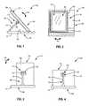
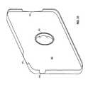
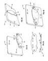
- FIG. 1illustrates a case for a portable electronic device oriented in a portrait viewing mode consistent with embodiments of the present disclosure
- FIG. 2illustrates a top perspective view of the case illustrated in FIG. 1 consistent with embodiments of the present disclosure
- FIG. 3illustrates a rear elevation view of the case illustrated in FIG. 1 consistent with embodiments of the present disclosure
- FIG. 4illustrates a rear elevation view of the case illustrated in FIG. 1 wherein the case is oriented in a landscape viewing mode consistent with embodiments of the present disclosure
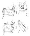
- FIG. 5illustrates another case for a portable electronic device configured in an open position and oriented in a portrait viewing mode consistent with embodiments of the present disclosure
- FIG. 6illustrates a top perspective view of the case illustrated in FIG. 5 consistent with embodiments of the present disclosure
- FIG. 7illustrates a rear elevation view of the case illustrated in FIG. 5 consistent with embodiments of the present disclosure
- FIG. 8illustrates a rear elevation view of the case illustrated in FIG. 5 configured in an open position and oriented in a landscape viewing mode consistent with embodiments of the present disclosure
- FIG. 9illustrates a top perspective view of the case illustrated in FIG. 5 configured in a closed position consistent with embodiments of the present disclosure
- FIG. 10illustrates a side elevation view of the case illustrated in FIG. 5 configured in a closed position consistent with embodiments of the present disclosure
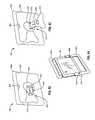
- FIG. 11illustrates another case for a portable electronic device oriented in a portrait viewing mode consistent with embodiments of the present disclosure
- FIG. 12illustrates a top perspective view of the case illustrated in FIG. 11 consistent with embodiments of the present disclosure
- FIG. 13illustrates another case for a portable electronic device oriented in a portrait viewing mode consistent with embodiments of the present disclosure
- FIG. 14illustrates a perspective view of the case illustrated in FIG. 13 consistent with embodiments of the present disclosure
- FIG. 15illustrates another case for a portable electronic device configured in an open position consistent with embodiments of the present disclosure
- FIG. 16illustrates an isometric view of a portion of the case illustrated in FIG. 15 consistent with embodiments of the present disclosure
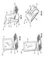
- FIG. 17illustrates a rotatable case for a portable electronic device configured in an open position consistent with embodiments of the present disclosure
- FIG. 18illustrates another case for a portable electronic device configured in an open position and oriented in a portrait viewing mode consistent with embodiments of the present disclosure
- FIG. 19illustrates a top perspective view of the case illustrated in FIG. 18 consistent with embodiments of the present disclosure
- FIG. 20illustrates a rear elevation view of the case illustrated in FIG. 18 consistent with embodiments of the present disclosure
- FIG. 21illustrates a rear elevation view of the case illustrated in FIG. 18 configured in an open position and oriented in a landscape viewing mode consistent with embodiments of the present disclosure
- FIG. 22illustrates a rotatable case in a landscape orientation consistent with embodiments of the present disclosure
- FIG. 23illustrates a rotatable case for a portable electronic device rotated into a portrait orientation consistent with embodiments of the present disclosure
- FIG. 24illustrates a rotatable case in a closed position securing a portable electronic device consistent with embodiments of the present disclosure
- FIG. 25illustrates a rotatable case securing a portable electronic device in a landscape orientation and a first opened position consistent with embodiments of the present disclosure
- FIG. 26illustrates a rotatable case supporting a portable electronic device at an angle in a landscape orientation and in a second opened position consistent with embodiments of the present disclosure
- FIG. 27illustrates a portable electronic device secured by a rotatable case including a pivot flap configured to allow the portable electronic device to be pivoted to a desired angle of inclination consistent with embodiments of the present disclosure
- FIG. 28illustrates a portable electronic device secured by a rotatable case including a grommet configured to allow the portable electronic device to be rotated from a portrait orientation to a landscape orientation and vice versa consistent with embodiments of the present disclosure
- FIG. 29illustrates a rear view of a rotatable case securing a portable electronic device in a portrait orientation consistent with embodiments of the present disclosure
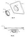
- FIG. 30illustrates an interaction between a support panel of a rotatable case and a securing panel via a grommet consistent with embodiments of the present disclosure
- FIG. 31illustrates a securing panel of a rotatable case and a first portion of a grommet consistent with embodiments of the present disclosure
- FIG. 32illustrates a support panel of a rotatable case including a pivot flap and a grommet consistent with embodiments of the present disclosure
- FIG. 33illustrates a rotatable case integrated into a larger case consistent with embodiments of the present disclosure
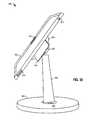
- FIG. 34illustrates a multi-pivot stand for a portable electronic device including a base, a vertical support, and a case configured in a landscape orientation consistent with embodiments of the present disclosure
- FIG. 35illustrates a multi-pivot stand for a portable electronic device including a data dock consistent with embodiments of the present disclosure
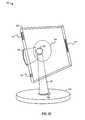
- FIG. 36illustrates a multi-pivot stand securing a portable electronic device in a landscape orientation consistent with embodiments of the present disclosure
- FIG. 37illustrates a rear elevation view of a multi-pivot stand consistent with embodiments of the present disclosure
- FIG. 38illustrates a side elevation view of a multi-pivot stand consistent with embodiments of the present disclosure
- FIG. 39illustrates a multi-pivot stand including a case coupled to a vertical support consistent with embodiments of the present disclosure
- FIG. 40illustrates a release lever configured to selectively release an upper connection member of a multi-pivot stand in order to rotate a case from a landscape orientation to a portrait orientation consistent with embodiments of the present disclosure
- FIG. 41illustrates another view of the release lever illustrated in FIG. 40 consistent with embodiments of the present disclosure
- FIG. 42illustrates another multi-pivot stand including a case configured to secure a portable electronic device capable of rotating from a landscape orientation to a portrait orientation consistent with embodiments of the present disclosure
- FIG. 43illustrates a multi-pivot stand including a case configured to vertically pivot about an upper connection member consistent with embodiments of the present disclosure
- FIG. 44illustrates another view of the multi-pivot stand illustrated in FIG. 43 consistent with embodiments of the present disclosure
- FIG. 45illustrates a multi-pivot stand including a case configured to horizontally pivot about an upper connection member consistent with embodiments of the present disclosure
- FIG. 46illustrates another view of the multi-pivot stand illustrated in FIG. 45 consistent with embodiments of the present disclosure
- FIG. 47illustrates a component view of a multi-pivot stand including a base, a lower connection member, a vertical support, and upper connection member, and a case configured to secure a portable electronic device consistent with embodiments of the present disclosure
- FIG. 48illustrates a base and a vertical support configured to be pivotably coupled via a lower connection member consistent with embodiments of the present disclosure
- FIG. 49illustrates a base and a vertical support configured to be pivotably coupled via another lower connection member consistent with embodiments of the present disclosure
- FIG. 50illustrates an exemplary base and vertical support configured to be pivotably coupled via a lower connection member consistent with embodiments of the present disclosure
- FIG. 51illustrates a holder for a portable electronic device consistent with embodiments of the present disclosure
- FIG. 52illustrates another view of the holder illustrated in FIG. 51 consistent with embodiments of the present disclosure
- FIG. 53illustrates a holder for a portable electronic device in a handheld configuration consistent with embodiments of the present disclosure
- FIG. 54illustrates another view of the holder illustrated in FIG. 53 consistent with embodiments of the present disclosure
- FIG. 56illustrates another view of the holder illustrated in FIG. 53 consistent with embodiments of the present disclosure
- FIG. 57illustrates the holder illustrated in FIG. 54 in a stand configuration consistent with embodiments of the present disclosure
- FIG. 58illustrates another view of the holder illustrated in FIG. 57 consistent with embodiments of the present disclosure
- FIG. 59illustrates a rotatable holder for a portable electronic device in a handheld configuration consistent with embodiments of the present disclosure
- FIG. 60illustrates another view of the rotatable holder illustrated in FIG. 59 consistent with embodiments of the present disclosure
- FIG. 61illustrates a component view of the rotatable holder illustrated in FIG. 59 consistent with embodiments of the present disclosure
- FIG. 63illustrates a handheld holder for a portable electronic device consistent with embodiments of the present disclosure
- FIG. 65illustrates another view of the handheld holder illustrated in FIG. 63 consistent with embodiments of the present disclosure
- FIG. 67illustrates another view of the handheld holder illustrated in FIG. 66 consistent with embodiments of the present disclosure
- FIG. 72illustrates another view of the rotatable coupling mechanism illustrated in FIG. 71 consistent with embodiments of the present disclosure
- FIG. 74illustrates a rotatable case for a portable electronic device oriented in a landscape configuration consistent with embodiments of the present disclosure
- FIG. 75illustrates the rotatable case illustrated in FIG. 74 oriented in a portrait configuration consistent with embodiments of the present disclosure
- FIG. 76illustrates the rotatable case illustrated in FIG. 74 configured in a stowage mode consistent with embodiments of the present disclosure
- FIG. 77illustrates a rear perspective view of the rotatable case illustrated in FIG. 74 oriented in a landscape consistent with embodiments of the present disclosure
- FIG. 80illustrates the support illustrated in FIG. 78 configured in a portrait orientation consistent with embodiments of the present disclosure
- FIG. 81illustrates the support illustrated in FIG. 78 configured in a landscape orientation consistent with embodiments of the present disclosure
- FIG. 84illustrates another view of the rotatable support illustrated in FIG. 82 consistent with embodiments of the present disclosure
- FIG. 85illustrates a handheld holder for a portable electronic device consistent with embodiments of the present disclosure
- FIG. 86illustrates a rear perspective view of the handheld holder illustrated in FIG. 85 consistent with embodiments of the present disclosure
- FIG. 87illustrates a support for a portable electronic device consistent with embodiments of the present disclosure
- FIG. 88illustrates a rear perspective view of the support illustrated in FIG. 87 consistent with embodiments of the present disclosure
- FIG. 90illustrates a rotatable case for a portable electronic device oriented in a landscape configuration consistent with embodiments of the present disclosure
- FIG. 91illustrates the rotatable case illustrated in FIG. 90 configured in a stowage mode consistent with embodiments of the present disclosure
- FIG. 92illustrates a rotatable case for a portable electronic device including an integrated keyboard oriented in a portrait configuration consistent with embodiments of the present disclosure
- FIG. 93illustrates the rotatable case illustrated in FIG. 92 oriented in a landscape configuration consistent with embodiments of the present disclosure
- FIG. 94illustrates the rotatable case illustrated in FIG. 92 configured in a stowage mode consistent with embodiments of the present disclosure
- FIG. 95illustrates a rear perspective view of the rotatable case illustrated in FIG. 92 consistent with embodiments of the present disclosure
- FIG. 96illustrates a rotatable case for a portable electronic device including an integrated keyboard oriented in a landscape configuration consistent with embodiments of the present disclosure
- FIG. 97illustrates a rear perspective view of the rotatable case illustrated in FIG. 96 consistent with embodiments of the present disclosure
- FIG. 98illustrates the rotatable case illustrated in FIG. 96 oriented in a portrait configuration consistent with embodiments of the present disclosure
- FIG. 99illustrates the rotatable case illustrated in FIG. 96 configured in a stowage mode consistent with embodiments of the present disclosure
- FIG. 100illustrates a support for a portable electronic device consistent with embodiments of the present disclosure
- FIG. 101illustrates a front perspective view the support illustrated in FIG. 100 consistent with embodiments of the present disclosure
- FIG. 102illustrates the support illustrated in FIG. 100 configured in a stowage mode consistent with embodiments of the present disclosure
- FIG. 103illustrates an interaction between a support panel of a rotatable case for a portable electronic device and a securing panel via a selectively detachable rotational mechanism consistent with embodiments of the present disclosure
- FIG. 104illustrates an interaction of a selectively detachable rotational mechanism and a securing panel of a rotatable case for a portable electronic device consistent with embodiments of the present disclosure
- FIG. 105illustrates a rotatable case including a user interface consistent with embodiments of the present disclosure.
- PEDsportable electronic devices
- notebook and tablet computerse.g., the Apple® iPadTM
- PDAsportable digital assistants
- smartphoneshave placed more computing power into the hands of users than the computing power of early computers that occupied an entire room.
- This portable computing powerhas enhanced both personal and business mobile productivity. Due to their portability, however, PEDs may be susceptible to damage.
- PEDsmay allow for viewing in a variety of orientations (e.g., portrait and/or landscape), but may not be configured to be easily used in multiple orientations.
- Embodiments of the present disclosureprovide an accessory case for a PED configured to protect the PED from damage.
- the accessory casemay be configured to enclose the PED and rotatably support the PED in at least two orientations.
- the casemay be configured to enclose and protect the PED in a closed position and support the PED upright and/or elevated (i.e., propped up) in an open position.
- the case 100can be configured to receive a PED 102 , and may further function to retain, carry, and protect the PED 102 .
- the PED 102can include on the front and/or the back face of the PED 102 a display 104 that is viewable in either a portrait orientation or a landscape orientation, a user input (not shown), and a data input/output port (not shown).
- the case 100may be configured such that the display 104 , user input, and data input/output port are accessible by a user of the PED 102 while the PED 102 is disposed in the case 100 .
- the case 100may include a protective display disposed over the display 104 .
- the case 100can assist a user in viewing the PED 102 when the display 104 is functioning in either the portrait or landscape orientation. This can be particularly advantageous, as users of a PED 102 may desire to alternate between using the PED 102 in the portrait and landscape orientations. Moreover, some users may prefer to use a PED 102 exclusively in either the portrait mode or the landscape mode. Since either group of users could use the case 100 effectively, the case 100 can advantageously serve to reduce sellers' inventories.
- the rotatable connector 112 or rotational mechanismmay be located at an upper end of the post 118 .
- the connectormay include a ball-and-socket joint 120 , which permits rotation about three mutually perpendicular axes. Stated otherwise, the ball-and-socket joint 120 may permit the holder 110 to rotate about an axis defined by the post 118 (as indicated at the double-headed arrow 122 ), and also permit the holder 110 to rotate about two mutually orthogonal axes that are each perpendicular to the axis defined by the post 118 (as indicated at the double-headed arrows 122 and 124 ).
- the holder 110may be configured to grip or otherwise secure the PED 102 .
- the holder 110may include a sleeve 128 , which may also be referred to as a pocket or a pouch, that is configured to retain therein the PED 102 .
- the sleeve 128may comprise a resilient material that can selectively expand so as to receive the PED 102 through a front opening and resiliently close about an outer edge of the PED 102 .
- the holder 110 and/or sleeve 128may also be configured to substantially cover the entirety of a back face of the PED 102 .
- the ball-and-socket joint 120may be centered relative to both the width and height of the holder 110 . As the support member 108 may be fixed relative to the base 106 , this may result in a different interaction between the bottom edge of the holder 110 and the channels 116 when the PED 102 is in the portrait and landscape orientations. For example, some channels 116 may be accessible in one orientation, but inaccessible in another.
- the connector 112can include a slide 130 or other suitable feature in addition to the ball-and-socket joint 120 so as to permit centering of the holder 110 .
- the base 106may not include a platform 114 that is solid between its outer edges.
- the support member 108may be substantially wider than the post 118 .
- the holder 110may not secure the PED 102 therein, but the PED 102 may rest on the holder 110 .
- any suitable connectors, straps, holders, or other devicesmay be used to secure the PED 102 to the holder 110 .
- the holder 110may include a clear protective sheet (e.g., a sheet of plastic) that covers a display 104 of the PED 110 .
- the holder 110may include an opening at a side or top edge thereof through which the PED 102 may be introduced into the holder 110 .
- the rotatable connector 112may not include a ball-and-socket joint 120 , but instead may include another suitable connection system that permits rotation about at least two mutually orthogonal axes.
- the ball-and-socket joint 120may be self-tensioning, and in further embodiments, the channels 116 are not used.
- the bottom edge of the holder 110may be secured to the base 106 using alternative suitable connectors including, for example, straps, snaps, hook and loop fasteners, and the like.
- FIGS. 5-10illustrate another case 200 for a PED 102 that can be used to assist in viewing a PED 102 .
- case 200may include similar features to case 100 illustrated in FIGS. 1-4 . Accordingly, like features may be designated in certain instances, but not all, with like reference numerals. Relevant disclosure set forth above regarding similarly identified features also may not be repeated hereafter.
- specific features of the case 100 illustrated in FIGS. 1-4may not be shown or identified by reference numerals in the drawings or specifically discussed in the written description that follows. However, such features may clearly be the same, or substantially the same, as features depicted in other embodiments and/or described with respect to such embodiments. Accordingly, the relevant descriptions of such features apply equally to the features of the case 200 . Any suitable combination of the features and variations of the same described with respect to the case 100 can be employed with the case 200 , and vice versa. This pattern of disclosure applies equally to further embodiments depicted in subsequent figures and described hereafter.
- the case 200may include a base 202 that comprises a display cover 204 that in certain configurations, may function as a platform.
- the case 200may further include a post 206 that is attached to the display cover 204 at a hinge 208 .
- the hinge 208can provide the base 202 with one or more a additional degrees of freedom in adjusting a viewing position of a holder 210 , as indicated by the double arrow 212 . This may also facilitate centering of the holder 210 in either a portrait or landscape orientation, as shown in FIG. 7 and FIG. 8 .
- the case 200can transition between various open orientations, as shown in FIGS. 5-7 (i.e., open, portrait) and FIG. 8 (i.e., open, landscape), and a closed orientation, as shown in FIGS. 9-10 .
- the case 200is in the landscape orientation when it is closed.
- the holder 210can encase a periphery and back face of the PED 102
- the display cover 204can cover a front face of the PED 102 , which include a display 104 .
- the post 206may be bent to facilitate alignment of the holder 210 and the display cover 204 .
- FIGS. 11-12illustrate another case 300 for a PED 102 that can be used to assist in viewing the PED 102 .
- the case 300can include a platform 302 that defines an opening 304 .
- the opening 304may be sufficiently large to receive a lower edge of a holder 306 therein in either a landscape or portrait orientation.
- the holder 306can include a support wall 308 and one or more connectors 310 , such as resilient straps, that may be configured to hold the PED 102 against the support wall 308 .
- FIGS. 13-14illustrate another case 400 for a PED 102 that can be used to assist in viewing the PED 102 .
- the case 400can include a platform 402 that defines two support legs 404 and a holder 408 .
- the holder 408can include a support wall 410 and two or more rests 412 , 414 that extend from the support wall 410 .
- the PED 102can rest against the support wall 410 and rest 412 when the holder 408 is configured for portrait orientation viewing, and can rest against the support wall 410 and rest 414 when the holder 408 is configured for landscape orientation viewing.
- the PED 102may not be physically secured to the holder 408 .
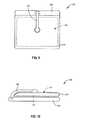
- FIGS. 15-16illustrate a case 500 configured to store items in addition to a PED 102 .
- the case 500may include a holder 502 such as the holders described above.
- the holder 502can comprise a back cover 504 and one or more connectors 506 , which can resemble the connectors described above.
- Other methods and devices for securing the PED 102 to the back cover 504are also possible, including those discussed herein with respect to other embodiments.
- the back cover 504can cover at least a portion of a rear face of the PED 102 .
- the back cover 504may include a storage region 506 , which can be configured to store one or more accessories.
- the storage region 506can include one or more storage compartments 508 , which can receive one or more accessories therein.
- the accessoriesmay be associated with the PED 102 , such as earphones (e.g., earbuds) 510 , a cleaning cloth 512 , cleaning solution 520 , cords (e.g., power cords), styluses, or the like. More or fewer compartments 508 than those shown in FIG. 15 may be used, and the compartments 508 may be of larger or smaller dimensions.
- one or more accessoriesmay be secured to the back cover 504 using other mechanical connection mechanisms including, for example, elastic straps.
- the compartments 508can be box-shaped, and may function as bins.
- the compartments 508may have hinged or removable covers for ready access to the contents thereof.
- the illustrated compartments 508can define a depth that is about the same or slightly greater than a thickness of the PED 102 .
- a front cover 514can be oriented substantially parallel to the back cover 504 when the case 500 is closed.
- one or more of the compartments 508may be shaped as sleeves or pouches.
- the sleevesmay be sealable, such as via snaps, buttons, hook and pile fastener, or the like.
- one or more of the compartments 508may be shaped as loops or elongated sleeves, which may be particularly suitable for receiving writing implements (e.g., pens, pencils, styluses) therein.
- the front cover 514may be connected to the back cover 504 in any suitable manner, such as via one or more hinges 516 , 518 .
- two hinges 516 , 518are present.
- a first hinge 518may be positioned adjacent to a base of the storage region 506
- a second hinge 516may be spaced from the first hinge 518 such that when the case 500 is closed, the second hinge 516 is positioned adjacent to an upper face of the storage region 506 .
- Such an arrangementcan aid in aligning the front and back covers 514 , 504 in a parallel configuration.
- a single hingecan instead be used, which may be positioned at the upper face of the storage region 506 .
- the storage region 506is positioned on the front cover 514 , or portions thereof are positioned on each of the front and back covers 514 , 504 .
- the storage region 506may be positioned at an outer side edge of one or more of the covers 504 , 514 , and in still other or further embodiments, the storage region 506 may be positioned along a top and/or bottom edge of one or more of the covers 504 , 514 .
- FIG. 17illustrates a rotatable case 600 for a PED 102 configured in an open position.
- the rotatable case 600may include similar features to the case 500 illustrated in FIGS. 15-16 and/or any combination of the various features and embodiments described in any of the cases and/or holders described herein.
- the rotatable case 600may include a rotational mechanism 602 coupling the PED 102 to the holder 502 , the back cover 504 , and/or via another PED securement mechanism allowing for variable rotation of the PED 102 relative to the rotatable case 600 .
- the rotational mechanism 602may include a rotational grommet coupling the PED 102 to the holder 502 , the back cover 504 , and/or via another PED securement mechanism allowing for variable rotation of the PED 102 relative to the rotatable case 600 .
- the rotational mechanism 602may include a ratcheting swivel or pivot, a ball and socket mechanism, a temporary adhesive, a releasable latch, a clip, one or more buttons, a suction cup, and/or one or more straps allowing for rotational securement.
- the rotational mechanism 602may snap into certain specific rotational orientations (e.g., portrait orientation and/or landscape orientation) and require rotational force to move to a different specific orientation.
- the rotation mechanism 602may not snap into specific orientations but may allow for rotational articulation in any number of orientations.
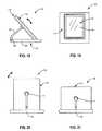
- FIGS. 18-21illustrate another case 700 for a PED 102 that can be used to assist in viewing a PED 102 .
- case 700may include similar features to case 100 illustrated in FIGS. 1-4 , case 200 illustrated in FIGS. 5-10 , and/or any combination of the various features and embodiments described in any of the cases and/or holders described herein.
- the case 700may include a base 702 that comprises a display cover 704 that in certain configurations, may function as a platform.
- the case 700may further include a post 706 that is attached to the display cover 704 at a hinge 708 .
- the hinge 708can provide the base 702 with one or more additional degrees of freedom in adjusting a viewing position of a holder 710 . This may also facilitate centering of the holder 710 in either a portrait or landscape orientation, as shown respectively in FIG. 20 and FIG. 21 .
- the case 700may include a rotational grommet 712 coupling the PED 102 and/or the holder 710 to the post 706 allowing for variable rotation of the PED 102 and/or the holder 710 relative to the post 706 in one or more directions.
- the rotational grommet 712may snap into certain specific rotational orientations (e.g., portrait orientation and/or landscape orientation) and require rotational force to move to a different specific orientation.
- the rotational grommet 712may not snap into specific orientations but may allow for rotational articulation in any number of orientations.
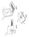
- FIG. 22illustrates a rotatable case 800 in a landscape orientation.
- the rotatable case 800includes a securing panel 802 configured to secure a PED (not shown).
- the rotatable case 800may include various access ports (such as 804 and 806 ) to facilitate interfacing a PED disposed within the case 800 with connector plugs, cables, headphones, speakers, and/or power adaptors.
- the rotatable case 800may include built-in cords to route power, connectivity, and/or headphone cables from a PED to an external device.
- a batterymay be built into a panel or pocket of rotatable case 800 .
- the rotatable case 800may have the ability to rotate securing panel 802 with respect to a supporting panel 808 and a base panel 810 .
- Any of a wide variety of rotatable securing devicesmay be employed to rotatably secure securing panel 802 to supporting panel 808 .
- bushings, flanged bushings, grommets, rivets, eyelets, plain bearings, bearings, and/or any combination thereofmay be employed to rotatably secure securing panel 802 to supporting panel 808 .
- a grommet 812may be configured to rotatably secure the securing panel 802 to the supporting panel 808 .
- the grommet 812may comprise a ring that may allow a logo to show through the hole in the middle of grommet 812 .
- one or more interchangeable accessories and/or insertsmay “snap” into the hole in the middle of grommet 812 including, for example, a logo insert, a proximity alarm or other loss prevention accessory, and the like.
- the hold in the middle of grommet 812may define an opening and/or aperture that may allow viewing of the interior of the rotatable case 800 and/or a portion of a PED (not shown) disposed therein (e.g., a portion of the PED including a logo)
- the base panel 810may be configured with channels or groves 814 to secure the bottom edge of securing panel 802 when the securing panel 802 is in an upright and/or elevated position.
- a frictional surfacee.g., rubberized surface or the like
- frictional contact patchesmay be utilized to secure the bottom edge of the securing panel 802 in an upright and/or elevated position.
- the supporting panel 808may be configured to provide a counterforce to the securing panel 802 in order to support securing panel 802 in an upright and/or elevated position.
- the supporting panel 808 and the base panel 810may comprise a single panel folded or bent at 816 .
- the relative proportions of the base panel 810 and the supporting panel 808may be adapted for a particular application.
- the rotatable case 800may be configured to support a PED at one or more angles relative to the base panel 810 and in a plurality of orientations, including portrait and landscape.
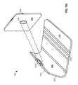
- FIG. 23illustrates a rotatable case 800 for a PED 102 rotated into a portrait orientation.
- the base panel 810may include one or more channels 814 configured to secure the bottom edge of a PED 102 and/or the bottom edge of a securing panel 802 .
- the rotatable casemay further include a supporting panel 808 configured to fold at 816 with respect to the base panel 810 .
- FIG. 22A comparison of FIG. 22 and FIG. 23 illustrates the ability to rotate the securing panel 802 with respect to supporting panel 808 consistent with embodiments disclosed herein.
- the grommet 812may allow a PED 102 to be rotated from a landscape orientation, as illustrated in FIG. 22 , to the portrait orientation illustrated in FIG. 23 .
- the securing panel 802 , base panel 810 , and/or supporting panel 808may provide protection to an enclosed PED 102 .
- the securing panel 802 , base panel 810 , and/or supporting panel 808may be configured to protect the PED 102 from scratches, from damage as a result of a fall, from extreme temperatures, and/or other conditions that may result in damage to the PED 102 .
- any portion of the rotating case 800may be reinforced with padding, metal, plastic, cardboard, rubber, and/or other material or combination thereof.
- the reinforcing materialmay utilize various folds, bends, and/or curvatures to obtain desirable resistance and/or resilience characteristics.
- fold 816may be configured to function as a bi-stable, tri-stable, or N-stable fold, allowing a user to selectively fold the support panel 808 with respect to the base panel 810 into one or more predetermined angles.
- the support panel 808may effectively “snap” into one or more predetermined positions in order to support the PED 102 at predetermined angles with respect to the base panel 810 .
- FIG. 24illustrates a rotatable case 800 in a closed position securing a PED 102 therein.
- the securing panel 802may include one or more access ports 804 .
- a grommet 812may serve to rotatably secure the support panel 808 to securing panel 802 .
- the grommet 812may include a see-through center circle making a portion of the PED 102 visible even when rotatable case 802 is in a closed position.
- a transparent materialmay cover the center of the circle made by grommet 812 .
- the center circle of grommet 812may be filled with any type of material, including the same type of material used for the support panel 808 and/or the securing panel 802 .
- the support panel 808may comprise a lower portion 818 and a pivot flap 820 .
- the pivot flap 820may be configured to fold or pivot with respect to the lower portion 818 of the support panel 808 .
- the grommet 812may be secured to the pivot flap 820 , allowing the grommet 812 and the securing panel 802 to pivot with respect to the lower portion 818 of the supporting panel 808 .
- any of a variety of fastenersmay be employed to selectively maintain the rotatable case 800 in the closed position.
- a fastenermay be configured to selectively maintain the securing panel 802 parallel to base panel 810 .
- the fastenermay comprise any of a variety of fasteners commonly employed in cases, bags, and luggage. Examples of possible closure mechanisms include, but are not limited to, straps, buttons, flaps, snaps, Velcro, hooks, clasps, clips, and combinations thereof.
- the ends of an elastic strapmay be secured to the base panel 810 and the strap may be selectively wrapped around the securing panel 802 . Accordingly, the securing panel 802 may be elastically maintained in a closed position.
- the rotatable case 800may include any of a wide variety of straps, handles, harnesses, and/or the like configured to enable a user to easily transport the rotatable case 800 .
- FIG. 25illustrates a rotatable case 800 securing a PED 102 in a landscape orientation and a first opened position.
- the support panel 808may be folded at 816 with respect to the base panel 810 .
- the grommet 812may be configured to rotatably secure the securing panel 802 with respect to the support panel 808 .
- the grommet 812may rotatably secure a pivot flap 820 of the support panel 808 to the securing panel 802 , thereby allowing the securing panel 802 to be pivoted with respect to a lower portion 818 of the support panel 808 .
- the grommet 812may allow a portion of the PED 102 to be seen through the center ring. For example, a logo included on the PED 102 may be visible.
- the base panel 810may include one or more channels 814 configured to prevent a bottom edge of the securing panel 802 from slipping when in an upright and/or elevated supported position.
- Alternative featuresmay be utilized in place of the one or more channels 814 including, for example, frictional contact patches, catches, magnets, protrusions, and/or other features configured to prevent a bottom edge of the securing panel 802 from slipping.
- the securing panel 802may include one or more access ports, such as a headphone access port 804 .
- FIG. 26illustrates a rotatable case 800 supporting a PED (not shown) at an angle in a landscape orientation and in a second opened position.
- FIG. 26illustrates the functionality of the pivot flap 820 (not visible) included in rotatable case 800 .
- the securing panel 802may be pivoted with respect to the supporting panel 808 .
- the support panel 808supports the securing panel 802 at an angle with respect to the base panel 810 .
- a first channel of channels 814prevents a bottom edge of the securing panel 802 from slipping along the base panel 810 .
- additional folding of the pivot flap 820 and/or the support panel 808 at 816may allow the PED 102 to be supported at various angles of inclination by placing the bottom edge of the securing panel 802 in a different channel of channels 814 .
- the securing panel 802may include one or more access ports, such as a headphone access port 804 .
- FIG. 27illustrates a PED 102 secured by a rotatable case 800 including a pivot flap 820 (not visible) configured to allow the PED 102 to be pivoted to a desired angle of inclination.
- the pivot flap 820may allow the PED 102 to be secured within the securing panel 802 to pivot with respect to the support panel 808 .
- the PED 102may be pivoted into a desired angle of inclination.
- the PED 102may be pivoted from the closed position illustrated in FIG. 24 , in which the PED 102 is parallel to base panel 810 , to any angle of inclination between with respect to the base panel 810 . Accordingly, the PED 102 may be pivoted until the securing panel 802 is again parallel with the base panel 810 and with the display 104 of the PED 102 facing up.
- the PED 102 secured by the securing panel 802may be pivoted to a desired angle of inclination.
- the support panel 808may provide sufficient support to maintain the PED 102 at the desired angle of inclination.
- One or more channels 814may prevent a bottom edge of the securing panel 810 from slipping along the base panel 810 .
- FIG. 28illustrates a PED 102 secured by a rotatable case 800 including a grommet 812 (not visible) configured to allow the PED 102 to be rotated from a portrait orientation to a landscape orientation and vice versa.
- a rotatable grommet 812may be configured to allow a PED 102 disposed in a securing panel 802 to be rotated from a portrait orientation to a landscape orientation and vice versa.
- the PED 102may be configured to rotate from a first landscape position, as illustrated in FIG. 22 to a second portrait position, as illustrated in FIG. 23 .
- the PED 102may be rotated 360 degrees into any desired orientation.
- the PED 102may be configured to rotate only into specific orientations. For example, at 0 degrees the PED 102 may be in a first landscape orientation; the PED 102 may be rotated 90 degrees to a first portrait orientation, rotated an additional 90 degrees to a second landscape orientation, and rotated a final 90 degrees to a second portrait position. In the second portrait position it may reach a stop and may be rotated in the opposite direction to return the PED 102 to prior orientations.
- the rotational mechanisme.g., grommet 812
- the case 800may snap into certain specific orientations and require rotational force to move to a different specific orientation.
- FIG. 29illustrates a rear view of a rotatable case 800 securing a PED 102 in a portrait orientation.
- a pivot flap 820may be folded with respect to a lower portion 818 of the support panel 808 .
- a PED 102 secured by the securing panel 802may be supported at one or more specific angles with respect to the support panel 808 and the base panel 810 (not visible).
- a grommet 812 or other rotational mechanismmay rotatably secure the securing panel 802 to the pivot flap 820 .
- the grommet 812may allow the PED 102 and the securing panel 802 to be rotated with respect to the support panel 808 , including, for example, in a portrait and/or landscape orientation.
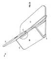
- FIG. 30illustrates an interaction between a support panel 808 of a rotatable case 800 and a securing panel 802 via a grommet 812 .
- the grommet 812may comprise a rear portion 812 and a front portion 822 .
- the rotatable case 800may include a base panel 810 with one or more channels 814 , a supporting panel 808 comprising a lower portion 818 , and a pivot flap 820 , and a rear portion 812 of the grommet.
- a securing panel 802including one or more access ports 804 , may be mounted to a front portion 822 of the grommet.
- the front portion 822 of the grommetmay be mated with the rear portion 812 of the grommet in order to rotatably secure the securing panel 802 to the pivot flap 820 .
- the securing panel 802may be free to rotate 360 degrees relative to the support panel 808 .
- the front portion 822 of the grommet and the rear portion 812 of the grommetmay be joined together during manufacturing or assembly and are not configured to be selectively separated by a user.
- a usermay selectively separate the front portion 822 of the grommet from the rear portion 812 in order to remove the securing panel 802 from the pivot flap 820 .
- the front portion 822 and the rear portion 812 of the grommetare inseparable and the grommet may be selectively detachable from the pivot flap 820 and/or the securing panel 102 .
- FIG. 31illustrates a securing panel 802 of a rotatable case 800 and a front portion of a grommet 822 .
- the securing panel 802may include sidewalls to protect and/or secure the edges of a PED 102 (not shown). According to various embodiments, a PED 102 may effectively snap into place within the securing panel 802 . Alternatively, a PED 102 may be secured within the securing panel 802 utilizing one or more straps, buckles, clips, adhesives, and/or similar features. The securing panel 802 may further utilize neoprene or rubber to selectively secure the PED 102 . Additionally, the sidewalls, or a portion thereof, of the securing panel 802 may wrap around the front of a secured PED 102 . In certain embodiments, the securing panel 802 may comprise a holder similar to the holders described herein.
- the securing panel 802may further include one or more access ports 804 , 806 , 824 .
- a headphone access port 804may be available.
- a volume rocker access port 806may be available.
- a power or connection access port 824may be available.
- a grommet portion 822may be configured to rotatably secure the securing panel 802 to a pivot flap 820 of a support panel 808 .
- the securing panel 802may comprise various materials such as plastic, rubber, metal, leather, faux leather, vinyl, nylon, and/or any of a wide variety of alternative decorative or useful materials utilized in cases, bags, luggage, and the like.
- the pivot flap 820may be connected to a lower portion 818 of the support panel 808 utilizing any of a variety of known pivotable connectors.
- the support panel 808including both the lower portion 818 and the pivot flap 820 may be manufactured using a material or fabric, such as leather, faux leather, and/or vinyl.
- the pivotable connection between the pivot flap 820 and the lower portion 818 of the support panel 808may be a sewn section of a similar or identical material.
- FIG. 33illustrates a rotatable case 800 integrated into a larger case 826 .
- the rotatable case 800may be integrated as an additional side pocket on a larger case 826 .
- the rotatable case 800may alternatively be integrated within an internal compartment of larger case 826 .
- a base panel 810may be a shared panel or wall of the larger case 826 ; and thus only include the remaining portions of the rotatable case 800 . That is, a wall of larger case 826 may share a common wall with the base panel 810 of rotatable case 800 .
- the rotatable case 800may include any combination of the various features and embodiments described in any of the cases described herein.
- the larger case 826may be configured with a handle 830 and a zipper 828 .
- the larger case 826may be any of a wide variety of cases, including a brief case, luggage, a laptop case, a case for a PED 102 , and the like.
- FIG. 34illustrates a multi-pivot stand 900 for a PED (not shown) including a base 902 , a vertical support 904 , and a case 906 configured in a landscape orientation.
- the base 902may be constructed of any shape and/or size suitable to adequately support a PED secured within the case 906 .
- the base 902may be weighted, include adjustable feet, have a no-slip bottom and/or top surface, and/or include a logo disposed thereon.
- a vertical support 904may be coupled to the base 902 via a lower connection member 908 .
- the lower connection member 908may comprise a swivel joint configured to allow the vertical support 904 to be rotated and pivoted in a variety of angles and directions with respect to the base 902 .
- the lower connection member 908may comprise a swivel joint configured to allow the vertical support 904 to be rotated but not pivoted, pivoted but not rotated, or rotated and pivoted.
- the lower connection membermay further comprise any variety of known rotatable and/or pivotable connections, including ball joints, ball and socket connections, bearings, pivot rods, slip rings, swivel joints, swing joints, and the like.
- the lower connection member 908may comprise a fixed connection member securing a vertical support 904 relative to the base 902 .
- the vertical support 904 and the base 902may also be manufactured as a single piece, thereby limiting relative movement between the vertical support 904 and the base 902 .
- the case 906may be configured to securing a PED (not shown).
- the case 906may comprise components and designs similar to the other cases and holders disclosed herein.
- the design of the case 906including its dimensions and positions of any access ports 910 - 914 may be adapted for a specific PED.
- a PEDmay be configured to snap into the case 906 or be secured therein using one or more corner securement members (e.g., resilient straps).
- the case 906may include flexible sidewalls configured to secure a PED.
- the flexible sidewallsmay be configured to secure a PED by wrapping around the sides and/or a portion of the front of a PED.
- the case 906may be coupled to the vertical support 904 via an upper connection member (not visible) configured to allow the case 906 to be rotated and/or pivoted with respect to the vertical support 904 .
- the stand 900may include a lever 916 configured to selectively lock and release the lower connection member 908 and or the upper connection member.
- the stand 900may further include a plurality of levers configured, for example, to control one or more of the connection members separately.
- FIG. 35illustrates a multi-pivot stand 900 for a PED (not shown) including a data dock 918 .
- the data dock 918may be configured to provide power and/or a data connection to a PED secured by a case 906 .
- the data dock 918may be communicatively coupled to an external connector 920 such as, for example, a USB connector and/or power connector, via a cable 922 .
- the type, shape, size and number of data dockets 918may be adapted for a specific PED.
- the data dock 918 and the external connector 920may be interchangeable with each other and/or other various alternative connectors.
- FIG. 36illustrates a multi-pivot stand 900 securing a PED 102 in a landscape orientation.
- the case portion 906 of the stand 900may be configured to secure the PED 102 therein.
- the PED 102may be configured to snap into the case 906 using one or more corner securement members (e.g., resilient straps).
- the case 906may include flexible sidewalls configured to secure the PED 906 .
- the flexible sidewallsmay be configured to secure the PED 906 by wrapping around the sides and/or a portion of the front of a PED 906 while still allowing a user to view the display 104 .
- FIG. 37illustrates a rear elevation view of a multi-pivot stand 900 .
- the stand 900may include a case 906 coupled to a vertical support 904 via an upper connection member 926 .
- the vertical support 904may be coupled to a base 902 via a lower connection member 908 such that the vertical support 904 may be rotated and/or pivoted in one or more directions with respect to the base 902 .
- the upper connection member 926may be a ball-and-socket type connection allowing the case 906 to be rotated and pivoted in one or more directions with respect to the vertical support 904 .
- the upper connection member 926may be generally described as a rotational mechanism.
- the casemay include one or more access ports 914 (e.g., power and/or data access ports).
- a release lever 916may be configured to selectively lock and release the upper connection member 926 and/or the lower connection member 908 .
- the release lever 916when locked, may be configured to selectively prevent the case 906 from pivoting and/or rotating in one or more directions relative to the vertical support 904 , the case 906 , and/or the base 902 .
- the release lever 916may be specifically configured to selectively lock and/or release the vertical and horizontal pivoting of the case 906 relative to the vertical support 904 .
- the case 906may be configured to rotate from a portrait to a landscape orientation regardless of the state of the release lever 916 .
- the case 906may be secured to the upper connection member 926 via a mount 924 .
- the case 906 and/or upper connection member 926may be selectively detached and/or attached from the mount 924 .
- FIG. 38illustrates a side elevation view of a multi-pivot stand 900 .
- the multi-pivot standmay include a vertical support 904 rotatably coupled to a base 902 via a lower connection member 908 .
- the lower connection member 908may allow the vertical support 904 to be rotated and/or pivoted in one or more directions relative to the base 902 .
- a case 906 configured to secure a PEDmay be coupled to an upper connection member 926 via a mount 924 .
- the case 906may be directly coupled to the upper connection member 926 .
- the upper connection member 926may be configured to rotatably couple the case 906 to the vertical support 904 such that the case 906 may be pivoted and/or rotated in one or more directions relative to the vertical support 904 .
- a release lever 916may be configured to selectively lock and release the movement of the upper connection member 926 .
- FIG. 39illustrates a multi-pivot stand 900 including a case 906 coupled to a vertical support 904 .
- the case 906may be coupled to the vertical support 904 via an upper connection member 916 (shown in dashed lines).
- the upper connection member 916may be coupled to the case 906 via a mount 924 (shown in dashed lines).
- the case 906may be configured to pivot and/or rotate in one or more directions relative to the vertical support 904 .
- the vertical support 904may be coupled to the base 902 via a lower connection member 908 and may be configured to pivot and/or rotate in one or more directions relative to the base 902 .
- a release lever 916may be configured to selectively lock and release the upper connection member 926 and/or the lower connection member 908 .
- the upper connection member 926 and/or the lower connection member 908may be configured to frictionally maintain their positions when the PED (not shown) is secured within the case 906 .
- frictionmay enable both connection members 926 , 908 to maintain their positions until acted on by an external force (e.g., from a user repositioning the stand 900 ).
- FIG. 40illustrates a release lever 916 configured to selectively release an upper connection member (not visible) of a multi-pivot stand 900 in order to rotate a case 906 from a landscape orientation to a portrait orientation.
- the release lever 916may be actuated by, for example, pulling it towards the case 906 .
- the release lever 916may be actuated by movement in another direction, by rotation in a particular direction, by pulling the lever 916 outward, and/or by pushing the lever 916 inward.
- the release lever 916may be a release button or other mechanical device configured to selectively actuate the configuration of the upper connection member 926 and/or the lower connection member 908 .
- FIG. 42illustrates another multi-pivot stand 900 including a case 906 configured to secure a PED (not shown) capable of rotating from a landscape orientation to a portrait orientation.
- a release lever(not shown) may need to be actuated prior to rotating the case 906 between orientations.
- the case 906may be free to rotate independent of the release lever.
- the release levermay be configured to selectively prevent the case 906 from vertically and horizontally pivoting but not prevent it from rotating.
- the case 906may be figured to lock (e.g., snap) into one or more desired orientations (e.g., every 90 degrees and/or in portrait/landscape orientations).
- a vertical support 904 coupled to the case 906may further be rotated and/or pivoted relative to a base 902 .
- FIGS. 43-44illustrate a multi-pivot stand 900 including a case 906 configured to vertically pivot about an upper connection member (not shown).
- a base 902may be coupled to a vertical support 904 that, in certain embodiments, may be rotatable and/or pivotable in one or more directions relative to the base 902 .
- the vertical support 904may be rotatably and/or pivotally coupled to the case 906 via an upper connection member (not visible).
- a release lever 916may be configured to selectively lock and release the upper connection member and control the rotation and/or pivoting of the case 906 relative to the vertical support 904 and/or the vertical support 904 relative to the base 902 .
- FIGS. 45-46illustrate a multi-pivot stand 900 including a case 906 configured to horizontally pivot about an upper connection member (not shown).
- a base 902may be coupled to a vertical support 904 that, in certain embodiments, may be rotatable and/or pivotable in one or more directions relative to the base 902 .
- the vertical support 904may be rotatably and/or pivotally coupled to the case 906 via an upper connection member (not visible).
- the vertical support 904may be further rotatably and/or pivotally coupled to the base 902 via a lower connection member 908 .
- a release lever 916may be configured to selectively lock and release the upper connection member and/or the lower connection member 908 and control the rotation and/or pivoting of the case 906 relative to the vertical support 904 and/or the vertical support 904 relative to the base 902 .
- the case 906may be horizontally rotated and/or pivoted with respect to the base 902 as illustrated. In certain embodiments, rotating and/or pivoting the case 906 may require that a release lever 916 be actuated.
- FIG. 47illustrates a component view of a multi-pivot stand including a base 902 , a lower connection member 908 , a vertical support 904 , an upper connection member 926 , and a case 906 configured to secure a PED.
- the standmay further include a release lever 916 and a mount 924 coupled to the case 906 .
- the vertical support 904may be rotatably and/or pivotally coupled to the base 902 .
- a lower connection member 908may comprise a ball joint that is rigidly or rotatably coupled to the vertical support 904 .
- the lower connection member 908may include a lower coupling pin 932 disposed thereon configured to be received by a lower coupling pin receptor 934 disposed in the base 902 .
- the lower coupling pin 932may be securely received by the lower coupling pin receptor 934 using a compression and/or friction fit.
- the lower coupling pin 932may be securely received by the lower coupling pin receptor 934 using a threaded mechanism incorporated into the lower coupling pin 932 and/or the lower coupling pin receptor 934 .
- the lower coupling pin 932may be securely received by the lower coupling pin receptor 934 using a mechanical latching mechanism incorporated into the lower coupling pin 932 and/or the lower coupling pin receptor 934 .
- the vertical support 904may be rotatably and/or pivotally coupled to the case 906 .
- an upper connection member 926may comprise a ball joint that is rigidly or rotatably coupled to the case 906 via, in certain embodiments, a mount 924 .
- the case 906 and/or upper connection member 926may be selectively detached and/or attached from the mount 924 .
- the upper connection member 926may include an upper coupling pin 928 disposed thereon configured to be received by an upper coupling pin receptor 930 disposed in the vertical support 904 .
- the upper coupling pin 928may be securely received by the upper coupling pin receptor 930 using a compression and/or friction fit.
- the upper coupling pin 928may be securely received by the upper coupling pin receptor 930 using a threaded mechanism incorporated into the upper coupling pin 928 and/or the upper coupling pin receptor 930 .
- the upper coupling pin 928may be securely received by the upper coupling pin receptor 930 using a mechanical latching mechanism incorporated into the upper coupling pin 928 and/or the upper coupling pin receptor 930 .
- a release lever 916may be configured to selectively pivotally and/or rotationally lock and release the upper connection member 926 and/or the lower connection member 908 .
- FIG. 48illustrates a base 902 and a vertical support 904 configured to be pivotably coupled via a lower connection member 1002 , 1004 .
- the lower connection membermay comprise a base ball 1004 rigidly coupled to the base 902 .
- a vertical support ball receptor 1002 coupled to the vertical support 904may be configured to mechanically and/or frictionally grasp the base ball 1004 .
- the vertical support 904may be rotated and/or pivoted relative to the base 902 via the lower connection member 1002 , 1004 independent of a selective release and locking mechanism such as, for example, a release lever.
- the vertical support 904may be rotated and/or pivoted relative to the base 902 via the lower connection member 1002 , 1004 at varying degrees of resistance based on the actuation of a selective release and locking mechanism.
- FIG. 49illustrates a base 902 and a vertical support 904 configured to be pivotably coupled via another lower connection member 1006 , 1008 .
- the lower connection membermay comprise a vertical support ball 1006 rigidly coupled to the vertical support 904 .
- a base ball receptor 1008 coupled to the base 902may be configured to mechanically and/or frictionally grasp the vertical support ball 1006 .
- the vertical support 904may be rotated and/or pivoted relative to the base 902 via the lower connection member 1006 , 1008 independent of a selective release and locking mechanism such as, for example, a release lever.
- the vertical support 904may be rotated and/or pivoted relative to the base 902 via the lower connection member 1006 , 1008 at varying degrees of resistance based on the actuation of a selective release and locking mechanism.
- FIG. 50illustrates an exemplary base 1010 and vertical support 904 configured to be pivotably coupled via a lower connection member 932 , 934 .
- the base 1010may include one or more leg members that may extend onto a surface the base 1010 rests upon.
- the vertical support 904may be rotatably and/or pivotally coupled to the base 1010 .
- a lower connection member 908may comprise a ball joint that is rigidly or rotatably coupled to the vertical support 904 .
- the lower connection member 908may include a lower coupling pin 932 disposed thereon configured to be received by a lower coupling pin receptor 934 disposed in the base 902 .
- the lower coupling pin 932may be securely received by the lower coupling pin receptor 934 using a compression and/or friction fit. In other embodiments, the lower coupling pin 932 may be securely received by the lower coupling pin receptor 934 using a threaded mechanism incorporated into the lower coupling pin 932 and/or the lower coupling pin receptor 934 . In further embodiments, the lower coupling pin 932 may be securely received by the lower coupling pin receptor 934 using a mechanical latching mechanism incorporated into the lower coupling pin 932 and/or the lower coupling pin receptor 934 .
- FIGS. 51-52illustrate a holder 1100 for a PED.
- the holder 1100may include a case 1102 , a hand grip 1104 , and a coupling mechanism 1106 , 1108 configured to securely attach the hand grip 1104 to the case 1102 .
- the case 1102may be configured to receive, secure, and carry a PED and may incorporate features of other embodiments of cases disclosed herein.
- the hand grip 1104may include a base plate 1110 and a strap 1112 coupled to the base plate 1110 .
- a usermay be able to slip a part of an appendage (e.g., a hand or forearm) between the base plate 1110 and the strap 1112 to secure the base plate 1110 to the user.
- the strap 1112may be formed integrally with the base plate 1110 . In other embodiments, the strap 1112 may pass through and/or wrap around at least a portion of the base plate 1110 .
- the inside of the strap 1112 and/or the base plate 1110may be lined at least in part with a pad and/or soft material (e.g., microfiber) to provide comfortable use.
- a pad and/or soft materiale.g., microfiber
- the base plate 1110may be a circular shape, as illustrated, to comfortably conform to the palm of a user's hand. In other embodiments, the base plate 1110 may comprise any suitable and/or ergonomic shape.
- the coupling mechanism 1106 , 1108may be configured to detachably secure the base plate 1110 of the hand grip 1104 to the case 1102 .
- the coupling mechanism 1106 , 1108may couple the hand grip 1104 to the case in a manner that allows the hand grip 1104 to be rotatable relative to the case 1102 .
- the coupling mechanism 1106 , 1108comprises hooks and loops, such as Velcro®, which can easily be separated to allow rotation.
- a loop portion 1108may be securely attached to the case 1102
- a hook portion 1106may be securely attached to the hand grip 1104 .
- the hand grip 1104may be secured to the case 1102 when the hook portion 1106 and the loop portion 1108 come into contact.
- the hand grip 1104can be rotated relative to the case 1102 by separating the hook portion 1106 and the loop portion 1108 (i.e., by separating the hand grip 1104 from the case 1102 ), rotating the hand grip 1104 as desired, and recoupling the hook portion 1106 and the loop portion 1108 .
- the coupling mechanism 1106 , 1108allows rotation of the case 1102 relative to the hand grip 1104 to any desired degree, including positions less than ninety degrees, thereby allowing the user to find a rotational orientation of the case 1102 that is comfortable.
- the loop portion 1108may be attached to the case 1102 with an adhesive. In another embodiment, the loop portion 1108 may be formed integrally with the case 1102 . Similarly, the hook portion 1106 may be attached to the base plate 1110 of the hand grip 1104 with an adhesive, or may be integrally formed with the base plate 1110 .
- the coupling mechanism 1106 , 1108can be any suitable securement device that allows the case 1102 to be rotated relative to the hand grip 1104 .
- the coupling mechanism 1106 , 1108may include a ratcheting swivel or pivot, a rotating grommet mechanism, a ball and socket mechanism, a temporary adhesive, a releasable latch, a clip, one or more buttons, a suction cup, and/or one or more straps allowing for rotational securement.
- the coupling mechanism 1106 , 1108may couple directly to a PED (not shown).
- the loop portion 1108may be constructed and arranged to be attached directly to the back of a PED.
- An adhesive designed to adhere to the back of the PEDmay be applied to the back of the loop portion 1108 .
- the hook portion 1106may include an adhesive to attach directly to the PED.
- FIGS. 53-56illustrate a holder 1200 for a PED (not shown) in a handheld configuration.
- the holder 1200may include a case 1202 configured to receive, secure, and retain a PED, and a sheath 1204 .
- the sheath 1204may be constructed and arranged to releasably secure to the case 1202 .
- the case 1202may include one or more cleats 1206 , 1208 and the sheath 1204 may include one or more holes 1210 constructed and arranged to releasably attach the sheath 1204 to the cleats 1206 , 1208 .
- FIG. 53illustrates a back perspective view of the holder 1200 with the sheath 1204 detached from the case 1202 .
- FIG. 54illustrates a back perspective view of the holder 1200 with the holes 1210 of the sheath 1204 attached to a pair of cleats 1208 in a first orientation.
- a usercan insert a hand or other appendage in between the sheath 1204 and the case 1202 and the sheath 204 , such that the holder 1200 can be secured to the user.
- the holder 1200 with the sheath 1204 in the first orientationis configured to be secured such that when the user's hand is positioned with fingers aligned horizontally across the user's body, the PED is oriented in a portrait orientation.
- the PEDmay be oriented in a landscape orientation.
- the sheath 1204can also function as a handle, such that a user can simply grasp the sheath 1204 . Accordingly, the sheath 1204 , in combination with the grasp of a user, can secure the case 1202 and PED disposed therein to a user.
- the sheath 1204can be detached from the first pair of cleats 1206 , as shown in FIG. 56 , rotated relative to the case 1202 , and attached to a second pair of cleats 1208 on the case 1202 , as shown in FIG. 54 . In this manner, the sheath 1204 may be rotatable to allow use of the PED in a portrait orientation or a landscape orientation.
- cleats 1206 , 1208may be attached directly to the PED rather than to the case 1202 . Further, in certain embodiments, any number of cleats 1206 , 1208 may be included allowing for multiple viewing orientations including, or in addition to, a portrait orientation and/or a landscape orientation.
- Additional holes 1210can be included on the sheath 1204 to allow for adjustable sizing and/or tension of the sheath 1204 to accommodate varying user hand sizes. Additionally, the inside of the sheath 1204 may be lined with a microfiber material and or a pad to provide comfortable use.
- FIG. 55is a top perspective view of the case 1202 , and a side view of the sheath 1204 .
- the sheath 1204may include one or more notches 1212 that, in certain embodiments, may be shaped and configured to receive an end of the case 1202 .
- the sheath 1204may be formed of a flexible material that can be bent into substantially a “U” shape, such that the end of the case 1202 can be inserted into notches 1212 .
- FIGS. 57-58illustrate a holder 1200 for a PED (not shown) in a stand configuration.
- the bottom edge of the sheath 1204can be set on a table or other flat surface and can function as a stand for the PED when an end of the case 1202 is disposed in the notches 1212 .
- the sheath 1204may also be configured to receive the PED at different orientations such that the user can insert the case 1202 and/or the PED 102 therein and view the display from a landscape orientation or, alternatively, a portrait orientation.
- the sheath 1204can include a pocket into which the user's hand or other appendage may be inserted. In other embodiments, the sheath 1204 may include an opening through which a user's hand can be inserted.
- the positioning of the cleats 1206 , 1208may be adjustable (e.g., adjustable via a sliding mechanism), to adjust sizing and/or positioning of the sheath 1204 relative to the case 1202 and/or PED. In other embodiments, the cleats 1206 , 1208 may be detachable or configured to be disposed within (i.e., pushed into) the case 1202 when not in use.
- FIGS. 59-62illustrate a rotatable holder 1300 for a PED 102 .
- the holder 1300may include a case 1302 , a hand grip 1304 , and a rotatable coupling member 1306 to rotatably attach the hand grip 1304 to the case 1302 .
- the case 1302may be configured to receive, secure, and carry the PED 102 , and may include any combination of the various features and embodiments described in any of the cases described herein.
- the case 1302may further comprise one or more kickstands 1308 that may be constructed and arranged to prop up the case 1302 in a viewing position.
- the kickstands 1308may be recessed into the case 1302 when not in use, and may rotate out from the case 1302 to prop up the case 1302 , as illustrated in FIG. 61 and FIG. 62 .
- the kickstands 1308may allow the case 1302 to operate as a stand to support the PED 102 in a substantially upright and/or elevated position.
- a first kickstand 1308may prop the case upright and/or elevated in a landscape orientation, as illustrated in FIG. 61
- a second kickstand 1308may prop the case upright and/or elevated in a portrait orientation, as illustrated in FIG. 62 .
- the hand grip 1304may include a knob or similar structure (e.g., a bulb, a handle, etc) that a user can easily grasp.
- the hand grip 1304in combination with a user's grasp may secure the case relative to the user's hand.
- the hand grip 1304is substantially a half sphere.
- the hand grip 1304may be formed in any suitable shape that can be easily grasped by a user.
- Hand grip 1304may also include finger depressions designed to comfortably receive one or more of a user's fingers.
- the hand grip 1304can be a mitt and/or similar glove-like or pocket-like structure coupled to the case 1302 by the rotatable coupling member 1306 .
- the mittcan be constructed and arranged with an opening to receive a hand of a user.
- the mittmay receive the hand of the user with the palm facing toward the back of the case 1302 , and may also be configured to receive the hand of the user with the palm facing away from the case 1302 .
- the mittmay further include a mounting plate to provide a rigid surface for attaching the mitt to the rotatable coupling member 1306 .
- the rotatable coupling member 1306may be configured to rotatably secure the hand grip 1304 to the case 1302 .
- the coupling member 1306may comprise a ratcheted swivel.
- the rotatable coupling member 1306may allow the case 1302 to rotate relative to the hand grip 1304 without decoupling the case 1302 from the hand grip 1304 and without a user releasing the hand grip 1304 .
- the rotation allowed by the rotatable coupling member 1306may be within a plane substantially parallel to a plane of the back surface of the case 1302 or a plane of the back surface of a PED 102 retained within the case 1302 .
- the rotation of the rotatable coupling member 1306may facilitate rotation of the PED 102 between a variety of orientations including, for example, a portrait orientation and a landscape orientation.
- the rotatable coupling member 1306may allow rotation up to at least ninety degrees, from portrait orientation to landscape orientation.
- the rotatable coupling member 1306may also allow 360 degree rotation, such that the PED 102 can be rotated to any angle.
- a ratcheting mechanism included within the rotatable coupling member 1306may substantially secure the case 1302 relative to the hand grip 1304 at various increments of rotation.
- the ratcheting mechanismmay be formed by a plurality of female detents interacting with one or more projecting members, such as spheres or half spheres that catch a detent as it passes during rotation.
- the rotatable coupling member 1306may allow rotation of the case 1302 relative to the hand grip 1304 to substantially any desired degree, including points less than ninety degrees, thereby allowing the user to find a rotational orientation of the case 1302 that is comfortable.
- the rotatable coupling member 1306may be configured such that the rotation may only lock into place at 90-degree intervals that correspond with the landscape and portrait orientations of the PED 102 .
- FIGS. 63-65illustrate a handheld holder 1400 for a PED 102 .
- the holder 1400may include a case 1402 , and a hand pocket 1404 attached to the case 1402 .
- the case 1402may be configured to receive, secure, and carry the PED 102 , and may include any combination of the various features and embodiments described in any of the cases described herein.
- the hand pocket 1404can be coupled to the back of the case 1402 and be configured to receive a hand of a user.
- the hand pocket 1404can be constructed and arranged to receive a hand of a user such that a PED 102 inserted into the case 1402 is oriented in a portrait orientation and also constructed and arranged to receive the hand of the user such that the PED 102 is oriented in a landscape orientation.
- the hand pocket 1404may be stitched to the back of the case 1402 , or otherwise secured using any appropriate securement method or device, including but not limited to an adhesive, hooks and loops, buttons, one or more zippers, and/or clamps.
- the hand pocket 1404may also be integrated into the case 1402 .
- the hand pocket 1404may include a first opening 1406 to receive a hand of a user and thereby secure the PED 102 relative to the hand of the user.
- the PED 102may be secured relative to the hand of the user such that when the user raises the hand substantially near the abdomen or chest, the PED 102 may be oriented in a portrait orientation.
- the user's handmay be received into the hand pocket 1404 with the palm facing toward the back of the PED 102 or, alternatively, with the palm facing away from the PED 102 .
- the hand pocket 1404may further include a second opening 1408 to receive the hand of the user and thereby secure the PED 102 relative to the hand of the user such that the PED 102 is oriented in a landscape orientation.
- the usermay remove a hand from the first opening 1406 and insert the hand into the second opening 1408 to change the orientation of the PED 102 .
- the case 1402is rotatable at least ninety degrees and allows operability of the PED 102 in either a portrait or a landscape orientation.
- the holder 1400may include a pocket 1404 that further includes a third opening 1410 opposite the first opening 1406 and a fourth opening 1412 opposite the second opening 1408 .
- a handcan be inserted into the hand pocket 1404 from any of four directions separated by ninety degrees, thus allowing orientation of the PED 102 in either of two possible landscape orientations (e.g., a first landscape orientation and then a second landscape orientation at 180 degrees from the first) and in either of two possible portrait orientations (e.g., a first portrait orientation and then a second at 180 degrees from the first).
- the hand pocket 1404may be connected to the PED 102 and/or case 1402 via a rotatable coupling mechanism 1414 , such as a grommet or any other rotatable connection and/or mechanism described herein.
- the pocket 1404may comprise a slightly rigid or reinforced side configured to be positioned adjacent to the PED 102 and/or the case 1402 and to be coupled to the rotatable coupling mechanism 1414 .
- FIGS. 66-67illustrate a handheld holder 1500 for a PED (not shown).
- the holder 1500may include a case 1502 and one or more hand pockets 1504 , 1506 coupled to the case 1502 .
- the case 1502may be configured to receive, secure, and carry the PED, and may include any combination of the various features and embodiments described in any of the cases described herein.
- One hand pocket 1506may be oriented to receive a hand of a user and thereby secure the holder such that a PED secured in the case 1502 is oriented in a portrait orientation.
- Another hand pocket 1504may be oriented to receive the hand of the user and thereby secure the holder such that a PED secured in the case 1502 is oriented in a landscape orientation.
- the usercan insert the hand into either of the hand pockets 1504 , 1506 , depending on the desired orientation of the PED.
- the case 1502is rotatable at least ninety degrees and allows operability of the PED in either a portrait or a landscape orientation.
- the holder 1500may comprise additional hand pockets 1504 , 1506 to allow additional degrees of rotation.
- the hand pockets 1504 , 1506may be stitched to the back of the case 1502 , or otherwise be secured using any appropriate securement method or device, including but not limited to an adhesive, hook and loop mechanisms, buttons, one or more zippers, and/or clamps.
- the hand pockets 1504 , 1506may also be integrated into the case 1502 .
- the hand pockets 1504 , 1506may be movable to one or more positions on the back of the case 1502 .
- a back side of the case 1502may include a loop portion of a hook and loop mechanism, and the hand pockets 1504 , 1506 may be attached anywhere on the backside of the case 1502 using a hook portion disposed thereon. In this manner, the hand pockets 1504 , 1506 may be positioned on the case 1502 to allow for a variety of viewing orientations.
- FIGS. 68-69illustrate a case 1600 for a PED (not shown).
- the case 1600may be configured to receive, secure, and carry the PED, and may include any combination of the various features and embodiments described in any of the cases described herein.
- the casemay include one or more kickstands 1604 configure to allow the case 1600 to function as a stand depending on the orientation of the kickstands 1604 (e.g., depending on whether kickstands are deployed).
- the kickstands 1604may be recessed into the case 1600 when not in use to prop the case 1600 in an upright and/or elevated position, and may rotate out from the case 1600 for use, as illustrated.
- the kickstands 1604may allow the case to operate as a stand to support a PED in a substantially upright and/or elevated position.
- a first kickstand 1604may prop the case 1600 upright and/or elevated in a landscape orientation, as illustrated in FIG. 68
- a second kickstand 1604may prop the case 1600 upright and/or elevated in a portrait orientation, as illustrated in FIG. 69 .
- the case 1600may also include a cover 1602 configured to be positioned over a PED inserted into the case 1600 and to substantially enclose and/or protect the PED.
- the cover 1602may snap into the case 1600 , thereby enclosing a PED disposed therein.
- the cover 1602may be strapped or fastened using any other mechanical means into the case 1600 .
- the cover 1602can be used to protect a PED disposed within the case 1600 when the PED is not in use.
- the cover 1602may comprise a transparent window through which a user can view and/or manipulate the PED, and thus the cover 1602 can remain positioned over the PED, both during use and when not in use.
- a window included in the cover 1602may be permanently open or may alternatively be selectively openable.
- FIG. 70illustrates a handheld holder 1700 for a PED (not shown).
- the handheld holder 1700may comprise a case 1702 and a hand pocket 1704 coupled to the case 1702 via a rotatable coupling mechanism 1706 .
- the rotatable coupling mechanism 1706may be a grommet or any other rotatable connection and/or mechanism described herein, and may be coupled directly to a PED rather than the case 1702 .
- the case 1702may be configured to receive, secure, and carry the PED, and may include any combination of the various features and embodiments described in any of the cases described herein.
- the hand pocket 1704may be a pocket, a strap, a pouch, a knob, a handle, and or any interface allowing a user's hand or other appendage to grasp or otherwise be secured into the hand pocket 1704 .
- the rotatable coupling mechanism 1706may allow a PED disposed in the case 1702 to be viewed in a variety of viewing orientations relative to the hand pocket 1704 .
- a usermay secure the hand pocket 1704 in a particular position (e.g., by securing a hand in the hand pocket 1704 or the like), and rotate the case 1702 in a variety of orientations relative to the hand pocket 1704 using the rotatable coupling mechanism 1706 .
- the rotatable coupling mechanism 1706may be configured to have one or more locking positions where the rotatable coupling mechanism 1706 requires a higher degree of rotational resistance to move the rotatable coupling mechanism from the non-locking positions.
- the rotatable coupling mechanism 1706may including locking positions where the case 1702 relative to the hand pocket 1704 is in a portrait orientation and a landscape orientation.
- FIGS. 71-73illustrate a rotatable coupling mechanism 1706 .
- the rotatable coupling mechanism 1706may be included in any of the case designs detailed herein and be used in such designs to change the orientation of a PED to one or more desired orientations (e.g., landscape and/or portrait).
- the rotatable coupling mechanism 1706may be substantially any cylindrical shape (e.g., a long shaft, a short cylinder similar to a hockey puck, etc.) and may comprise two complementary halves 1708 , 1710 configured to rotate relative to each other and interact so as to create one or more locking positions.
- the complementary surfaces of the halves 1708 , 1710may comprise one or more protrusions 1712 and one or more depressions 1714 to implement a locking position.
- the protrusions 1712 of a first half 1708may complement and conform to the depressions 1714 of a second half 1710 , as illustrated in FIG. 72 .
- the protrusions 1712 of the second half 1710may complement and conform to the depressions 1714 of the first half 1708 .
- the protrusions 1712 of the first half 1708may rotate between non-locking positions (i.e., where the protrusions 1712 of the first half 1708 abut the protrusions 1712 of the second half 1710 ) and locking positions (i.e., where the protrusions 1712 of the first half 1708 abut the depressions 1714 of the second half 1710 ).
- the protrusions 1712 and depressions 1714may alternate as illustrated and may be any functionally appropriate shape including, a wave shape, a set of complementary teeth, and the like.
- the protrusions 1712may have a rounded shape and be configured such that a first protrusion 1712 on a first half 1708 allows a second protrusion 1712 on the opposing second half 1710 to smoothly rotate over and past the first protrusion as the halves 1708 , 1710 rotate relative to one another.
- the depressions 1714may have a rounded shape.
- the transition from a protrusion 1712 to a depression 1714may be seamless and continuous to form a gentle rounded surface as illustrated. Accordingly, the halves 1708 , 1710 can easily be rotated relative to one another, and thereby transitioned between locking positions, while the halves 1708 , 1710 are in abutment to one another and without being separated.
- the protrusions 1712may be jagged without a rounded shape.
- the protrusions 1712may comprise complementary teeth.
- the teethmay be triangular in shape, alternating between protrusions 1712 and depressions 1714 .
- the halves 1708 , 1710may need to be pulled apart and separated before rotation can occur.
- the transition from protrusion 1712 to depression 1714may be more pronounced and/or non-continuous, such that there is a separation between each protrusion 1712 and depression 1714 .
- each half 1708 , 1710comprises four protrusions 1712 and four depressions 1714 .
- the rotatable coupling mechanism 1706comprises four locking positions.
- the four locking positionsmay each correspond to ninety degrees of rotation.
- additional protrusions 1712 and depressions 1714may be provided so as to allow additional locking positions at smaller degrees of rotation.
- fewer protrusions 1712 and depressions 1714may be provided as well to provide fewer locking positions.
- the connecting member 1716itself may comprise a biasing member, such as a spring 1718 or an elastic material, that may provide a biasing force, as illustrated in FIG. 73 .
- the biasing forcemay be provided to urge the halves 1708 , 1710 toward one another.
- the biasing forcemay also urge the rotatable coupling mechanism 1706 toward a locking position (i.e., by urging the protrusions 1712 of the first half 1708 toward a position abutting the depressions 1714 of the second half 1710 and vice versa).
- an external forcesuch as, for example, gravity may provide a biasing force to urge the halves 1708 , 1710 toward one another.
- FIGS. 74-77illustrate a rotatable case 1800 for a PED 102 .
- the case 1800may include a holder 1802 configured to receive, secure, retain, and carry the PED 102 , and may include any combination of the various features and embodiments described in any of the cases and/or holders described herein.
- the holder 1802may be configured to retain the PED 102 by mechanically securing the PED 102 at its corners.
- the holder 1802may retain the PED 102 using a compression and/or snap fit mechanism.
- the case 1800may further include a cover 1804 , 1806 comprising a base portion 1804 and a support portion 1806 .
- the base portion 1804 and the support portion 1806may be coupled at a fold 1808 allowing for the base portion 1804 to hinge with respect to the support portion 1806 .
- the base portion 1804 and the support portion 1806may be formed integrally and the fold 1808 may be formed as part of the base portion 1804 and the support portion 1806 .
- the base portion 1804 , the support portion 1806 , and the fold 1808may be separate components.
- the holder 1802 and/or the cover 1804may provide protection to an enclosed PED 102 .
- the holder 1802 , the base portion 1804 , and/or the support portion 1806may be reinforced with padding, metal, plastic, cardboard, rubber, and/or other materials or any combination thereof.
- the fold 1808may include various folds, bends, and/or curvatures in material to obtain desirable resistance and/or resilience characteristics.
- the fold 1808may be configured to function as a bi-stable, tri-stable, or N-stable fold, allowing a user to selectively vary the relative angle between the base portion 1804 and the support portion 1806 into one or more predetermined angles.
- the support portion 1806may effectively “snap” into one or more predetermined positions relative to the base portion 1804 .
- the base portion 1804may be coupled to a vertical support 1810 via a hinge 1812 .
- the vertical support 1810may be configured to support in part the holder 1802 in an upright and/or elevated position allowing for viewing of the display 104 of the PED 102 .
- the vertical support 1810may be coupled to the holder 1802 via a rotational mechanism 1814 allowing for variable rotation of the holder 1802 relative to the vertical support 1810 .
- the rotational mechanism 1814may include a rotational grommet secured to the vertical support 1810 and the holder 1802 allowing for variable rotation of the holder 1802 relative to the vertical support 1810 .
- the rotational mechanism 1814may include a ratcheting swivel or pivot, a ball and socket mechanism, a temporary adhesive, a releasable latch, a clip, one or more buttons, a suction cup, and/or one or more straps allowing for rotational securement.
- the rotational mechanism 1814may snap into certain specific rotational orientations (e.g., portrait orientation, as illustrated in FIG. 75 , and/or landscape orientation, as illustrated in FIG. 74 ) and require rotational force to move to a different specific orientation.
- the rotation mechanism 1814may not snap into specific orientations but may allow for rotational articulation in any number of orientations.
- the vertical support 1810may be coupled to the holder 1802 via a non-rotatable connection including, for example, a fixed and/or hinged mechanism.
- the vertical support 1810may be configured to allow for its length to be adjusted using a sliding track or similar adjustable mechanism. In some embodiments, by adjusting the length of the vertical support 1810 , the relative distance between the base portion 1804 and the holder 1802 may be adjusted. In certain embodiments, the length of the vertical support 1810 may be configured to be adjusted to one or more predetermined positions via a selective locking mechanism or the like. In other embodiments, the vertical support 1810 may have a fixed length.
- the back of the vertical support 1810may include one or more channels 1816 .
- the channelsmay be configured to receive an edge of the support portion 1806 .
- the base portion 1804may be rotated relative to the vertical support 1810 about the hinge 1812 and rested on a work surface.
- the angle of the support portion 1806may be adjusted relative to the base portion 1804 via the fold 1808 , thereby adjusting a viewing angle of the PED 102 included in the holder 1802 .
- an end of the support portion 1804may be positioned in one of the channels 1816 , allowing for the desired viewing angle to be sustained by the case 1800 .
- the end of the support portion 1806may be secured in the channels 1816 via a compression fit.
- a selective securement mechanismmay be used to secure the end of the support portion 1806 in the channels 1816 that may include a magnetic connection, a snap, a button, a clip, or the like.
- the case 1800may be reconfigured by a user into a stowage configuration, as illustrated in FIG. 76 .
- the base portion 1804 and the support portion 1806may be articulated around the hinge 1812 so as to cover the display 104 of the PED 102 .
- the fold 1808may be adjusted to allow the base portion 1804 and the support portion 1806 to be substantially co-planar.
- reconfiguration of the case 1800 in a stowage configuredmay require that the length of the vertical support 1810 be adjusted using a sliding track mechanism or the like.
- the base portion 1804 and the support portion 1806may be secured to the holder 1802 and/or the PED 102 in the stowage configuration via a magnetic connection, one or more releasable clips, straps, and/or other locking mechanisms allowing for the case 1800 to be selectively locked into a stowage configuration and selectively released from the stowage configuration.
- FIGS. 78-81illustrate a support 1900 for a PED 102 .
- the support 1900may include a holder 1902 , 1904 configured to receive, secure, retain, and carry the PED 102 , and may include any combination of the various features and embodiments described in any of the cases and/or holders described herein.
- the holder 1902 , 1904may be configured to retain the PED 102 by mechanically securing the PED 102 using a compression fit mechanism or the like.
- the holder 1902 , 1904may include a main portion 1902 and a selectively removable top portion 1904 .
- a PED 102may be disposed within the main portion 1902 when the top portion 1904 is removed and securely locked within the main portion 1902 when the top portion 1904 is securely coupled to the main portion 1902 using a selective latching mechanism 1906 or the like.
- the main portion 1902 and the top portion 1904may be aligned using one or more ribs and/or channels or similar alignment mechanism.
- the holder 1902 , 1904may further comprise one or more kickstands 1908 that may be configured and arranged to prop up the holder 1902 , 1904 in a viewing position.
- the kickstand 1908may be recessed into the holder 1902 , 1904 when not in use, as illustrated in FIG. 78 and FIG. 79 , and may be rotated out from the holder 1902 , 1904 via a hinge 1910 to prop up the holder 1902 , 1904 , as illustrated in FIG. 80 and FIG. 81 .
- the kickstand 1908may allow the support 1900 to operate as a stand to support the PED 102 disposed in the holder 1902 , 1904 in a substantially upright and/or elevated position.
- a viewing angle of a PED 102 disposed within the support 1900may be adjusted. For example, by increasing the degree to which the kickstand 1908 is rotated out from the holder 1902 , 1904 via the hinge 1910 , the PED 102 may be viewed at a less upright and/or elevated angle. Similarly, by decreasing the degree to which the kickstand 1908 is rotated out from the holder 1902 , 1904 , the PED 102 may be viewed at a more upright and/or elevated angle.
- the hinge 1910may be configured to allow the kickstand 1908 to rotate out from the holder 1902 , 1904 at one or more predetermined angles using, for example, a ratcheting mechanism or the like.
- the length of the kickstand 1908may be adjusted using a sliding and/or ratcheting mechanism 1912 .
- the relative viewing angle of the PED 102 disposed within the support 1900may be adjusted. For example, by lengthening the kickstand 1908 , the PED 102 may be viewed at a more upright and/or elevated angle. Similarly, by shortening the kickstand 1908 , the PED 102 may be viewed at a less upright and/or elevated angle.
- the length of the kickstand 1908may be configured to be adjusted to one or more predetermined positions via a selective locking mechanism 1914 or the like. In alternative embodiments, the kickstand 1908 may have a fixed length.
- a rest 1916may be disposed at an end of the kickstand 1908 and be configured to rest on a working surface when the support 1900 is in use.
- the rest 1916may include one or more edges configured to be positioned parallel to a working surface when the support 1900 is oriented in one or more orientations.
- the rest 1916may include an edge configured to sit parallel to a working surface when the PED 102 is viewed in a portrait configuration.
- the rest 1916may include an edge configured to sit parallel to a working surface when the PED 102 is viewed in a landscape orientation.
- the rest 1916may comprise a material configured to prevent the rest 1916 from easily sliding along the work surface (e.g., rubber or the like).
- FIGS. 82-84illustrate a rotatable support 2000 for a PED 102 .
- the support 2000may include a holder 2002 , 2004 configured to receive, secure, retain, and carry the PED 102 , and may include any combination of the various features and embodiments described in any of the cases and/or holders described herein.
- the holder 2002 , 2004may be configured to retain the PED 102 by mechanically securing the PED 102 using a compression fit mechanism or the like.
- the holder 2002 , 2004may include a main portion 2002 and a selectively removable top portion 2004 .
- the holder 2002 , 2004may define a window allowing for a display 104 of the PED 102 to be viewed by a user. Further, the holder 2002 , 2004 may include one or more access windows 2008 allowing for PED 102 accessories (e.g., cameras) and/or interfaces (e.g., buttons, switches, knobs, etc.) to be accessed through the holder 2002 , 2004 .
- PED 102 accessoriese.g., cameras
- interfacese.g., buttons, switches, knobs, etc.
- the holder 2002 , 2004may further comprise one or more kickstands 2010 that may be configured and arranged to prop up the holder 2002 , 2004 in a viewing position.
- the kickstand 2010may be recessed into the holder 2002 , 2004 when not in use, as illustrated in FIG. 82 , and may be rotated out from the holder 2002 , 2004 via a hinge 2012 to prop up the holder 2002 , 2004 , as illustrated in FIG. 83 . In this manner, the kickstand 2010 may allow the support 2000 to operate as a stand to support the PED 102 disposed in the holder 2002 , 2004 in a substantially upright and/or elevated position.
- the hinge 2012may be configured to allow the kickstand 2010 to rotate out from the holder 2002 , 2004 at one or more predetermined angles using, for example, a ratcheting mechanism or the like.
- the rest 2014may comprise a material configured to prevent the rest 2014 from easily sliding along the work surface (e.g., rubber or the like).
- the length of the kickstand 2010may be adjusted using a sliding and/or ratcheting mechanism 2016 .
- the relative viewing angle of the PED 102 disposed within the support 2000may be adjusted. For example, by lengthening the kickstand 2010 , the PED 102 may be viewed at a more upright and/or elevated angle. Similarly, by shortening the kickstand 2010 , the PED 102 may be viewed at a less upright and/or elevated angle.
- the length of the kickstand 2010may be configured to be adjusted to one or more predetermined positions via a selective locking mechanism or the like. In alternative embodiments, the kickstand 2010 may have a fixed length.
- the rotational mechanism 2018may snap into certain specific rotational orientations (e.g., portrait orientation and/or landscape orientation) and require rotational force to move to a different specific orientation. In alternative embodiments, the rotation mechanism 2018 may not snap into specific orientations but may allow for rotational articulation in any number of orientations. Further, in certain embodiments, the kickstand 2010 may be coupled to the holder 2002 , 2004 via a non-rotatable connection including, for example, a fixed and/or hinged mechanism.
- the support 2000may not include a holder 2002 , 2004 , and the kickstand 2010 may be coupled to the PED 102 directly or via a rotation mechanism 2018 .
- the kickstand 2010 and or rotation mechanism 2018may be coupled to the PED 102 using one or more straps, buckles, clips, adhesives, and/or other mechanical structures integrated into the PED 102 and/or the kickstand 2010 and/or rotation mechanism 2018 .
- FIGS. 85-86illustrate a handheld holder 2100 for a PED 102 .
- the handheld holder 2100may include a case 2102 configured to receive, secure, retain, and carry the PED 102 , and may include any combination of the various features and embodiments described in any of the cases and/or holders described herein.
- the case 2102may be configured to retain the PED 102 by mechanically securing the PED 102 about an outer periphery thereof.
- the case 2102may retain the PED 102 using a compression and/or snap fit mechanism.
- a hand grip 2104may be included on a back of the handheld holder 2100 .
- the hand grip 2104may be mounted to a rotational mechanism 2110 coupled to the back of the case 2102 .
- the hand grip 2104may include a center hub 2108 and one or more straps 2106 extending outward therefrom and coupled to an outer periphery of the rotational mechanism 2110 .
- a usermay be able to slip a part of an appendage (e.g., a hand or forearm as illustrated in FIG. 85 ) between the rotational mechanism 2110 and the straps 2106 to secure the case 2102 to the user.
- the hand grip 2104may be formed integrally with the rotational mechanism 2110 .
- the hand grip 2104 or a portion thereofmay pass through and/or wrap around at least a portion of the rotational mechanism 2110 .
- the center hub 2108may include a mechanism such that when it is rotated, the length of the one or more straps 2106 extending outward therefrom are adjusted. For example, when the center hub 2108 is rotated in a particular direction, the length of the one or more straps 2106 may be shortened. Similarly, when the center hub 2108 is rotated in a different direction, the length of the one or more straps may be increased. By allowing for adjustment of the length of the one or more straps 2106 , the hand grip 2104 may be sized so as to be secured to a user's appendage (e.g., a hand or forearm) regardless of size.
- a user's appendagee.g., a hand or forearm
- the holder 2100may not include a case 2102 and the hand grip 2104 may be coupled to the PED 102 directly or via a rotation mechanism 2110 .
- the hand grip 2104 and/or rotation mechanism 2110may be coupled to the PED 102 using one or more straps, buckles, clips, adhesives, and/or other mechanical structures integrated into the PED 102 and/or the hand grip 2104 and/or the rotation mechanism 2110 .
- FIGS. 87-89illustrate a support 2200 for a PED 102 .
- the support 2200may include a case 2202 configured to receive, secure, retain, and carry the PED 102 , and may include any combination of the various features and embodiments described in any of the cases and/or holders described herein.
- the case 2202may be configured to retain the PED 102 by mechanically securing the PED 102 using a compression fit mechanism or the like.
- the PED 102may be secured within the case 2202 by one or more securement clips 2204 located on an end of the case 2202 configured to receive the PED 102 , as illustrated in FIG. 89 .
- the case 2202may define a window allowing a user to view a display 104 of the PED 102 . Further, the case 2202 may include one or more areas exposing the PED 102 . In certain embodiments, these areas may aid in removing the PED 102 from the case 2202 .
- the rotatable case 2300may include one or more horizontal supports 2302 extending from a rotational hub 2304 and coupled to an outer edge of the PED 102 via horizontal support clips 2306 .
- the horizontal support clips 2306may be coupled to the outer edge of the PED 102 using a compression fit.
- the horizontal support clips 2306may be secured to the outer edge of the PED 102 using releasable clips, straps, or any other selectively locking mechanism.
- the length of the horizontal supports 2302may be adjusted so that the horizontal support clips 2306 fit securely around the outer edge of the PED 102 . In this manner, the horizontal supports 2302 may be adjusted to secure PEDs 102 having varied dimensions.
- the rotational hub 2304may include a rotational mechanism configured to allow the horizontal supports 2302 to rotate relative to one or more vertical supports 2308 .
- the rotational mechanismmay include a rotating grommet, a ratcheting swivel or pivot, a ball and socket mechanism, a temporary adhesive, a releasable latch, a clip, one or more buttons, a suction cup, and/or one or more straps allowing for rotational securement of the horizontal supports 2302 to the vertical supports 2308 .
- the vertical supports 2308may be coupled to an outer edge of the PED 102 via vertical support clips 2310 .
- the vertical support clips 2310may be coupled to the outer edge of the PED 102 using a compression fit.
- the vertical support clips 2310may be secured to the outer edge of the PED 102 using releasable clips, straps, or any other selectively locking mechanism.
- the length of the vertical supports 2308may be adjusted so that the vertical support clips 2310 fit securely around the outer edge of the PED 102 . In this manner, the vertical supports 2308 may be adjusted to secure PEDs 102 having varied dimensions.
- the other ends of the PED supports 2312may be coupled to hinges 2314 configured to allow the PED supports 2312 to rotate in one or more directions relative to the hinges 2314 .
- the hinges 2314may be in turn rigidly coupled to a base 2316 .
- the base 2316may be placed on a working surface.
- the PED 102may be raised and oriented in a viewing position by placing a bottom edge of the PED 102 on a top surface of the base 2316 , as illustrated in FIG. 90 .
- the bottom edge of the PED 102may be positioned in one or more channels (not shown) included on the top surface of the base 2316 that may be similar to the channels 116 illustrated in FIGS. 1-2 .
- the bottom edge of the PED 102may be rested on a material included on the top surface of the base 2316 designed to prevent the bottom edge of the PED 102 from easily sliding along the surface (e.g., rubber, suede, or the like).
- the rotatable case 2300may be reconfigured by a user into a stowage configuration, as illustrated in FIG. 91 .
- the PED 102may be articulated around the PED supports 2312 , hinges 2314 , and/or the horizontal support clips 2306 so as to cover the display 104 of the PED 102 with the top surface of the base 2316 .
- interfaces 2318 disposed on the top surface of the base 2316may also be protected from external damage.
- reconfiguration of the case 2300 in a stowage configurationmay require that the length of the PED supports 2312 be adjusted.
- the base 2316may be secured to the PED 102 in the stowage configuration via a magnetic connection, one or more releasable clips, straps, and/or other locking mechanism allowing for the rotatable case 2300 to be selectively locked into a stowage configuration and selectively release from the stowage configuration.
- FIGS. 92-95illustrate a rotatable case 2400 for a PED 102 including an integrated keyboard 2406 .
- the rotatable case 2400may include a holder (not shown) configured to receive, secure, retain, and carry the PED 102 , and may include any combination of the various features and embodiments described in any of the cases and/or holders described herein.
- the rotatable case 2400may couple directly to the PED 102 .
- the rotatable case 2400may include a holder 2402 extending from a rotational hub 2408 and coupled to the outer edges of the PED 102 .
- the holder 2402may include clips coupled to the outer edge of the PED 102 using a compression fit.
- the holder 2402may be secured to the outer edge of the PED 102 using releasable clips, straps, or any other selectively locking mechanism.
- the length of the holder 2402may be adjusted so that the holder 2402 fits securely around the outer edge of the PED 102 . In this manner, the holder 2402 may be adjusted to secure PEDs 102 having varied dimensions.
- the rotational hub 2408may include a rotational mechanism configured to allow the holder 2402 to rotate relative to a vertical support 2404 .
- the rotational mechanismmay include a rotating grommet, a ratcheting swivel or pivot, a ball and socket mechanism, a temporary adhesive, a releasable latch, a clip, one or more buttons, a suction cup, and/or one or more straps allowing for rotational securement of the holder 2402 to the vertical support 2404 .
- the vertical support 2404may be configured to support the PED 102 in a substantially upright and/or elevated position allowing for viewing of the display 104 .
- the rotational hub 2408may snap into certain specific rotational orientations (e.g., portrait orientation, as illustrated in FIG. 92 , and/or landscape orientation, as illustrated in FIG. 93 ) and require rotational force to move to a different specific orientation.
- the rotational hub 2408may not snap into specific orientations but may allow for rotational articulation in any number of orientations.
- the vertical support 2404may be coupled to the holder 2402 via a non-rotatable connection including, for example, a fixed and/or hinged mechanism.
- the vertical support 2404may be configured to allow for its length to be adjusted using a sliding track or similar adjustable mechanism. In certain embodiments, the length of the vertical support 2404 may be configured to be adjusted to one or more predetermined positions via a selective locking mechanism or the like. In other embodiments, the vertical support 2404 may have a fixed length.
- the vertical support 2404may be coupled to a base 2410 via a hinge 2412 allowing the vertical support 2404 to rotate relative to the base 2410 in one or more directions. In certain embodiments, by varying the orientation of the vertical support 2404 relative to the base 2410 via the hinge 2412 , a viewing angle of the PED 102 disposed in the holder 2402 may be adjusted.
- the base 2410may include one or more integrated interfaces 2406 configured to interface with the PED 102 .
- the base 2410may include a keyboard 2406 .
- the interfaces 2406may include a touch pad, a speaker, or any other interface device capable of being integrated into the base 2410 .
- the base 2410may be secured to the PED 102 in the stowage configuration via a magnetic connection, one or more releasable clips, straps, and/or other locking mechanism allowing for the rotatable case 2400 to be selectively locked into a stowage configuration and selectively release from the stowage configuration.
- FIGS. 96-99illustrate a rotatable case 2500 for a PED 102 including an integrated keyboard 2502 .
- the rotatable case 2500may include a holder 2504 configured to receive, secure, retain, and carry the PED 102 , and may include any combination of the various features and embodiments described in any of the cases and/or holders described herein.
- the holder 2504may be configured to retain the PED 102 by mechanically securing the PED 102 using a compression fit mechanism or the like.
- the holder 2504may retain the PED 102 by securing one or more corners of the PED 102 .
- the holder 2504may be coupled to a rotational mechanism 2506 which in turn may be coupled to a vertical support 2508 via an upper hinge 2510 .
- the rotational mechanism 2506may be configured to allow the holder 2504 to rotate relative to the vertical support 2508 .
- the rotational mechanism 2506may include a rotating grommet, a rotating hub, a ratcheting swivel or pivot, a ball and socket mechanism, a temporary adhesive, a releasable latch, a clip, one or more buttons, a suction cup, and/or one or more straps allowing for rotational securement of the holder 2504 to the vertical support 2508 .
- the vertical support 2508may be configured to support the PED 102 in a substantially upright and/or elevated position allowing for viewing of the display 104 .
- the rotational mechanism 2506may snap into certain specific rotational orientations (e.g., portrait orientation, as illustrated in FIG. 98 , and/or landscape orientation, as illustrated in FIG. 96 , and require rotational force to move to a different specific orientation.
- the rotational mechanism 2506may not snap into specific orientations but may allow for rotational articulation in any number of orientations.
- the vertical support 2508may be coupled the holder 2504 via a non-rotatable connection including, for example, a fixed and/or hinged mechanism, and may be connected directly or via the upper hinge 2510 .
- the vertical support 2508may be further coupled to a base 2514 via a lower hinge 2512 allowing the vertical support 2508 to rotate relative to the base 2514 in one or more directions.
- a viewing angle of the PED 102 disposed in the holder 2404may be adjusted.
- the base 2514may include one or more integrated interfaces 2502 configured to interface with the PED 102 .
- the base 2514may include a keyboard.
- the interfaces 2502may include a touch pad, a speaker, or any other interface device capable of being integrated into the base 2514 .
- the interfaces 2502may be configured to extend outward from the base 2514 on one or more sides and/or in one or more directions. In certain embodiments, by extending outwards, the interfaces 2502 may increase the effective surface area of the base 2514 on a working surface, thereby increasing the stability of the rotational case 2500 when in use.
- the effective usable area of the interfaces 2502may be increased.
- the interfaces 2502include a keyboard, as illustrated in FIGS. 96-98
- extending the keyboard outwardsmay increase the size of the keyboard.
- the interfaces 2502may be slid along a track or similar mechanism into the base 2514 when not in use, as illustrated in FIG. 99 , and be slid out of the base 2514 when in use, as illustrated in FIGS. 96-98 .
- the rotatable case 2500may be reconfigured by a user into a stowage configuration, as illustrated in FIG. 99 .
- the PED 102may be articulated around the upper hinge 2510 and the lower hinge 2512 so as to cover the display 104 of the PED 102 with the top surface of the base 2514 .
- interfaces 2502 disposed on the top surface of the base 2514may also be protected from external damage.
- reconfiguration of the case 2500 into a stowage configurationmay require that the length of the vertical support 2508 be adjusted and/or a particular rotational orientation of the PED 102 be achieved.
- the base 2514may be secured to the PED 102 in the stowage configuration via a magnetic connection, one or more releasable clips, straps, and/or other locking mechanism allowing for the rotatable case 2500 to be selectively locked into a stowage configuration and selectively release from the stowage configuration.
- FIGS. 100-102illustrates a support 2600 for a PED 102 .
- the support 2600may include a holder (not shown) configured to receive, secure, retain, and carry the PED 102 , and may include any combination of the various features and embodiments described in any of the cases and/or holders described herein.
- a rotatable kickstand 2602may be coupled to the holder and configured to support the holder and PED 102 in an substantially upright and/or elevated position
- the support 2600may include a rotatable kickstand 2602 coupled directly to the PED 102 one or more straps, buckles, clips, adhesives, and/or any other similar attachment feature.
- the rotatable kickstand 2602may incorporate similar features to the kickstand 1908 described above in reference to FIGS. 78-81 .
- the viewing angle of the PED 102may be adjusted by articulating the rotatable kickstand 2602 in various manners (e.g., changing the relative angle between the kickstand 2602 and the PED 102 , adjusting the length of the kickstand 2602 , and the like).
- the viewing orientation of the PED 102may be adjusted by rotating the relative position of the kickstand 2602 relative to the PED 102 using a rotational mechanism.
- the support 2600may further include a cover 2604 which in some embodiments, may include one or more integrated interfaces 2606 configured to interface with the PED 102 .
- the cover 2604may include a keyboard.
- the interfaces 2606may include a touch pad, a speaker, or any other interface device capable of being integrated into the cover 2604 .
- the support 2600may be reconfigured by a user into a stowage configuration, as illustrated in FIG. 102 .
- the cover 2604may be secured over a side of the PED 102 so as to cover the display 104 of the PED 102 with the cover 2604 and protect it from external damage.
- interfaces 2606 disposed on an inner surface of the cover 2604may also be protected from external damage.
- the cover 2604may be secured to the PED 102 in the stowage configuration via a magnetic connection, one or more releasable clips, straps, and/or other locking mechanism allowing for the cover 2604 to be selectively locked into a stowage configuration and selectively release from the stowage configuration.
- the rotatable case 2700may include a base 2706 with one or more support channels 2710 and a supporting panel 2708 comprising a lower portion 2712 and a pivot flat 2714 .
- the selectively detachable rotational mechanism 2716 , 2718may include a rear portion 2716 coupled to the supporting panel 808 and a front portion 2718 coupled to the securing panel 2702 , which may include one or more access ports 2704 .
- the rear portion 2716may be coupled to the pivot flat 2714 of the supporting panel 2708 .
- the front portion 2718 and the rear portion 2716 of the grommetmay be joined together during manufacturing or assembly and are not configured to be selectively separated by a user.
- a usermay selectively separate the front portion 2718 from the rear portion 2716 in order to remove the securing panel 2702 from the pivot flap 2714 , as illustrated in FIG. 103 .
- the front portion 2718 and the rear portion 2716 of the grommetare inseparable and the grommet may be selectively detachable from the pivot flap 2714 and/or the securing panel 2702 .
- FIG. 104illustrates an interaction of a selectively detachable rotational mechanism 2716 , 2718 and a securing panel 2702 of a rotatable case 2700 for a PED (not shown).
- FIG. 104illustrates the securing panel 2702 of FIG. 103 mounted on a surface 2720 which may, as shown, be a back of a car seat.
- the surface 2720may be refrigerator door, a wall, a door, a desk, a window, and/or any other appropriate surface.
- the rear portion 2716 of the rotational grommetmay be mounted to the surface 2720 , and the front portion 2718 may be secured to the rear portion 2716 , thereby rotationally securing the securing panel 2702 to the surface 2720 .
- the rear portion 2716may be mounted to the surface 2720 using, for example, an adhesive, hook and loop mechanisms, buttons, one or more zippers, and/or clamps.
- the rear portion 2716may be mounted to the surface 2720 using a mechanism allowing for rotation of the rear portion 2716 in one or more directions relative to the surface 2720 such as, for example, a hinge, a ball and socket joint, and the like.
- the mechanism allowing for rotation of the rear portion 2716 in one or more directionsmay allow a viewing angle of a PED disposed in the securing panel 2702 to be adjusted relative to the surface 2720 .
- FIG. 105illustrates a rotatable case 2800 including a user interface 2820 .
- the rotatable case 2800may include a securing panel 2802 configured to receive, secure, retain, and carry the PED (not shown), and may include any combination of the various features and embodiments described in any of the cases and/or holders described herein.
- the rotatable case 2800may include various access ports (such as 2804 and 2806 ) to facilitate interfacing a PED disposed within the rotatable case 2800 with connector plugs, cables, headphones, speakers, and/or power adaptors.
- the rotatable case 2800may have the ability to rotate the securing panel 2802 with respect to a supporting panel 2808 and a base panel 2810 .
- Any of a wide variety of rotatable securing devicesmay be employed to rotatably secure securing panel 2802 to supporting panel 2808 .
- bushings, flanged bushings, grommets, rivets, eyelets, plain bearings, bearings, and/or any combination thereofmay be employed to rotatably secure the securing panel 2802 to the supporting panel 2808 .
- a grommet 2812may be configured to rotatably secure the securing panel 2802 to the supporting panel 2808 .
- the grommet 2812may comprise a ring that may allow a logo to show through the hole in the middle of grommet 2812 .
- one or more interchangeable accessories and/or insertsmay “snap” into the hole in the middle of grommet 2812 including, for example, a logo insert, a proximity alarm or other loss prevention accessory, and the like.
- the supporting panel 2808may be configured to provide a counterforce to the securing panel 2802 in order to support securing panel 2802 in an upright and/or elevated position.
- the supporting panel 2808 and the base panel 2810may comprise a single panel folded or bent at 2816 .
- the relative proportions of the base panel 2810 and the supporting panel 2808may be adapted for a particular application.
- the rotatable case 2800may be configured to support a PED at one or more angles relative to the base panel 2810 and in a plurality of orientations, including portrait and landscape.
- any suitable combination of various embodiments, or the features thereof,is contemplated.
- any methods disclosed hereinmay comprise one or more steps or actions for performing the described method. These method steps and/or actions may be interchanged with one another. In other words, unless a specific order of steps or actions is required for proper operation of the embodiment, the order and/or use of specific steps and/or actions may be modified.
- any reference to “one embodiment,” “an embodiment,” or “the embodiment”means that a particular feature, structure, or characteristic described in connection with that embodiment is included in at least one embodiment.
- the quoted phrases, or variations thereof, as recited throughout this specificationare not necessarily all referring to the same embodiment.
- various featuresare sometimes grouped together in a single embodiment, figure, or description thereof for the purpose of streamlining the disclosure. This method of disclosure, however, is not to be interpreted as reflecting an intention that any claim require more features than those expressly recited in that claim. Rather, inventive aspects lie in a combination of fewer than all features of any single foregoing disclosed embodiment. It will be apparent to those having skill in the art that changes may be made to the details of the above-described embodiments without departing from the underlying principles set forth herein.
Landscapes
- Engineering & Computer Science (AREA)
- General Engineering & Computer Science (AREA)
- Mechanical Engineering (AREA)
- Theoretical Computer Science (AREA)
- Computer Hardware Design (AREA)
- Human Computer Interaction (AREA)
- Physics & Mathematics (AREA)
- General Physics & Mathematics (AREA)
- Microelectronics & Electronic Packaging (AREA)
- Casings For Electric Apparatus (AREA)
- Telephone Set Structure (AREA)
- Purses, Travelling Bags, Baskets, Or Suitcases (AREA)
Abstract
Description
Claims (28)
Priority Applications (2)
| Application Number | Priority Date | Filing Date | Title |
|---|---|---|---|
| US13/791,445US8746449B2 (en) | 2010-06-07 | 2013-03-08 | Portable electronic device case accessories and related systems and methods |
| US14/099,436US8783458B2 (en) | 2010-06-07 | 2013-12-06 | Portable electronic device case accessories and related systems and methods |
Applications Claiming Priority (5)
| Application Number | Priority Date | Filing Date | Title |
|---|---|---|---|
| US35228610P | 2010-06-07 | 2010-06-07 | |
| US36804710P | 2010-07-27 | 2010-07-27 | |
| US42143110P | 2010-12-09 | 2010-12-09 | |
| US13/155,266US9170611B2 (en) | 2010-06-07 | 2011-06-07 | Portable electronic device case accessories and related systems and methods |
| US13/791,445US8746449B2 (en) | 2010-06-07 | 2013-03-08 | Portable electronic device case accessories and related systems and methods |
Related Parent Applications (1)
| Application Number | Title | Priority Date | Filing Date |
|---|---|---|---|
| US13/155,266ContinuationUS9170611B2 (en) | 2010-06-07 | 2011-06-07 | Portable electronic device case accessories and related systems and methods |
Related Child Applications (1)
| Application Number | Title | Priority Date | Filing Date |
|---|---|---|---|
| US14/099,436ContinuationUS8783458B2 (en) | 2010-06-07 | 2013-12-06 | Portable electronic device case accessories and related systems and methods |
Publications (2)
| Publication Number | Publication Date |
|---|---|
| US20130186682A1 US20130186682A1 (en) | 2013-07-25 |
| US8746449B2true US8746449B2 (en) | 2014-06-10 |
Family
ID=45063643
Family Applications (7)
| Application Number | Title | Priority Date | Filing Date |
|---|---|---|---|
| US13/155,266Active2034-02-07US9170611B2 (en) | 2010-06-07 | 2011-06-07 | Portable electronic device case accessories and related systems and methods |
| US13/601,799Active2034-10-22US10139861B2 (en) | 2010-06-07 | 2012-08-31 | Portable electronic device case accessories and related systems and methods |
| US13/791,445ActiveUS8746449B2 (en) | 2010-06-07 | 2013-03-08 | Portable electronic device case accessories and related systems and methods |
| US14/099,436ActiveUS8783458B2 (en) | 2010-06-07 | 2013-12-06 | Portable electronic device case accessories and related systems and methods |
| US16/183,443Active2033-03-27US11360513B2 (en) | 2010-06-07 | 2018-11-07 | Portable electronic device case accessories and related systems and methods |
| US17/656,533Active2031-06-17US12271227B2 (en) | 2010-06-07 | 2022-03-25 | Portable electronic device case accessories and related systems and methods |
| US19/087,871PendingUS20250284317A1 (en) | 2010-06-07 | 2025-03-24 | Portable electronic device case accessories and related systems and methods |
Family Applications Before (2)
| Application Number | Title | Priority Date | Filing Date |
|---|---|---|---|
| US13/155,266Active2034-02-07US9170611B2 (en) | 2010-06-07 | 2011-06-07 | Portable electronic device case accessories and related systems and methods |
| US13/601,799Active2034-10-22US10139861B2 (en) | 2010-06-07 | 2012-08-31 | Portable electronic device case accessories and related systems and methods |
Family Applications After (4)
| Application Number | Title | Priority Date | Filing Date |
|---|---|---|---|
| US14/099,436ActiveUS8783458B2 (en) | 2010-06-07 | 2013-12-06 | Portable electronic device case accessories and related systems and methods |
| US16/183,443Active2033-03-27US11360513B2 (en) | 2010-06-07 | 2018-11-07 | Portable electronic device case accessories and related systems and methods |
| US17/656,533Active2031-06-17US12271227B2 (en) | 2010-06-07 | 2022-03-25 | Portable electronic device case accessories and related systems and methods |
| US19/087,871PendingUS20250284317A1 (en) | 2010-06-07 | 2025-03-24 | Portable electronic device case accessories and related systems and methods |
Country Status (14)
| Country | Link |
|---|---|
| US (7) | US9170611B2 (en) |
| EP (1) | EP2529281B1 (en) |
| JP (1) | JP5879337B2 (en) |
| KR (1) | KR20130082443A (en) |
| CN (2) | CN102576239B (en) |
| AU (2) | AU2011265093B2 (en) |
| BR (1) | BR112012028204A2 (en) |
| CA (2) | CA2908213C (en) |
| DK (1) | DK2529281T3 (en) |
| ES (1) | ES2543617T3 (en) |
| NZ (2) | NZ594007A (en) |
| PH (1) | PH12012501328A1 (en) |
| SG (1) | SG183467A1 (en) |
| WO (1) | WO2011156275A2 (en) |
Cited By (38)
| Publication number | Priority date | Publication date | Assignee | Title |
|---|---|---|---|---|
| US20140104761A1 (en)* | 2012-10-11 | 2014-04-17 | Fu-Yi Hsu | Protective sheath |
| US20140328019A1 (en)* | 2013-05-03 | 2014-11-06 | Wistron Corporation | Fixing device for fixing a portable electronic device and portable electronic system therewith |
| US20150041622A1 (en)* | 2012-04-16 | 2015-02-12 | Iordanka Koleva Mulhern | Rotating Mechanism for Computer or Similar Device |
| US20150041244A1 (en)* | 2013-08-07 | 2015-02-12 | Rackel Industries Limited | Universal Tablet Holder |
| US20150122851A1 (en)* | 2012-04-16 | 2015-05-07 | Iordanka Koleva Mulhern | Rotating Mechanism for Computer or Similar Device |
| US20150153791A1 (en)* | 2013-12-02 | 2015-06-04 | Chih-Juh Wong | Protective case for electronic equipment |
| US20150212542A1 (en)* | 2014-01-27 | 2015-07-30 | Lenovo (Singapore) Pte. Ltd. | Multi-angle stand for an information handling device |
| US20150301560A1 (en)* | 2011-10-20 | 2015-10-22 | Darryl D. Garland, Sr. | Case and Mounting Apparatus for a Tablet Computer |
| USD750089S1 (en) | 2015-08-17 | 2016-02-23 | FLB Group Limited | Tablet computer stand |
| US20160088749A1 (en)* | 2014-09-19 | 2016-03-24 | Wistron Corp. | Electronic device and stand thereof |
| US20160366997A1 (en)* | 2015-05-20 | 2016-12-22 | World Richman Manufacturing Corporation | Pivot Panel Case Construction for an Electronic Device |
| US9580209B2 (en) | 2012-02-14 | 2017-02-28 | ACCO Brands Corporation | Electronic tablet case with internal easel |
| US9675148B2 (en) | 2015-03-18 | 2017-06-13 | Targus International Llc | Extendable, universal case for portable electronic devices |
| DE212015000238U1 (en) | 2014-10-06 | 2017-06-19 | Thule Inc. | Protective cover for an electronic device |
| USD795238S1 (en)* | 2015-10-02 | 2017-08-22 | Ye Eun Kim | Mobile phone case |
| US9778702B2 (en)* | 2014-02-27 | 2017-10-03 | Hewlett-Packard Development Company, L.P. | Protective cover for a device |
| US20180168303A1 (en)* | 2015-06-05 | 2018-06-21 | Hartley & Marks Publishers Inc. | Tablet case and method of manufacture |
| USD848436S1 (en) | 2018-02-07 | 2019-05-14 | Bank Of America Corporation | Enclosure for electronic device |
| US10361741B2 (en) | 2012-08-02 | 2019-07-23 | GoDirectInc.com, Inc. | Mobile device enclosure system |
| USD855057S1 (en) | 2018-01-16 | 2019-07-30 | Bank Of America Corporation | Enclosure for electronic device |
| US10389398B1 (en)* | 2017-01-23 | 2019-08-20 | Dennis Garcia | Folio boost for tablet device |
| US10628637B2 (en) | 2018-01-16 | 2020-04-21 | Bank Of America Corporation | Enclosure for card reader equipped device |
| US20200132282A1 (en)* | 2018-10-24 | 2020-04-30 | Verilux, Inc. | Lamp with Stand |
| US10782732B2 (en)* | 2013-09-21 | 2020-09-22 | Otter Products, Llc | Mounting system for electronic device |
| USD909391S1 (en) | 2019-12-02 | 2021-02-02 | Fintie Llc | Case for electronic device with multi-angle stand cover |
| USD921637S1 (en) | 2019-11-22 | 2021-06-08 | Fintie Llc | Case for electronic device with pencil holder |
| USD922390S1 (en) | 2020-01-27 | 2021-06-15 | Fintie Llc | Case for electronic device with multi-angle stand cover |
| USD922391S1 (en) | 2020-01-27 | 2021-06-15 | Fintie Llc | Case for electronic device with detachable keyboard |
| USD923011S1 (en) | 2020-02-19 | 2021-06-22 | Fintie Llc | Stand cover for electronic device |
| USD940723S1 (en) | 2020-07-09 | 2022-01-11 | Fintie Llc | Case for electronic device with multi-angle stand |
| USD942982S1 (en) | 2020-06-22 | 2022-02-08 | Fintie Llc | Case for electronic device with multi-angle rotatable stand |
| US20220291715A1 (en)* | 2010-06-07 | 2022-09-15 | Targus International Llc | Portable electronic device case accessories and related systems and methods |
| US11500426B2 (en)* | 2021-03-23 | 2022-11-15 | Lenovo (Singapore) Pte. Ltd. | Display system |
| USD980225S1 (en) | 2020-02-19 | 2023-03-07 | Fintie Llc | Protective case for electronic device |
| USD986251S1 (en) | 2021-09-20 | 2023-05-16 | Fintie Llc | Stand cover for electronic device |
| USD991936S1 (en) | 2020-08-31 | 2023-07-11 | Fintie Llc | Case for electronic device with flexible multi-configuration stand |
| US20240041173A1 (en)* | 2022-08-02 | 2024-02-08 | Dong Guan Mercury Home Appliance Products LTD. | Tablet computer protective cover |
| USD1046870S1 (en)* | 2020-12-08 | 2024-10-15 | Samsung Electronics Co., Ltd. | Accessory panel for television receiver |
Families Citing this family (385)
| Publication number | Priority date | Publication date | Assignee | Title |
|---|---|---|---|---|
| US20140197048A1 (en)* | 2007-06-06 | 2014-07-17 | Belkin International, Inc. | Multiple orientation support for electronic device with touch screen and method |
| US20110287402A1 (en)* | 2007-08-02 | 2011-11-24 | Michael Sanford | Method and apparatus for novel embodiments to repurpose eink ereaders as writing devices to enable children to write on digital workbook learning content |
| US11134580B2 (en) | 2010-07-08 | 2021-09-28 | Zagg Inc | Protective cover for portable electronic device and associated systems and methods |
| US20120024733A1 (en)* | 2010-07-28 | 2012-02-02 | Openpeak Inc. | Protective element and support structure |
| US8328008B2 (en)* | 2010-08-10 | 2012-12-11 | Incase Designs Corp. | Case for electronic tablet |
| USD658187S1 (en) | 2011-03-17 | 2012-04-24 | Incase Designs Corp. | Foldable front cover for electronic tablet |
| USD658188S1 (en)* | 2011-03-17 | 2012-04-24 | Incase Designs Corp. | Foldable front cover for electronic tablet |
| CA2812842A1 (en)* | 2010-09-28 | 2012-04-05 | Bernard John Graham | Stand and/or support for planar or tablet computing devices |
| US9267641B2 (en) | 2010-10-15 | 2016-02-23 | Jon Simon Gillespie-Brown | Multimedia device stand |
| US20120097831A1 (en)* | 2010-10-21 | 2012-04-26 | Lollygig LLC | Display device case, stand and accessory system |
| TWI363026B (en) | 2010-12-13 | 2012-05-01 | Chi Mei Comm Systems Inc | Multi-functional protecting bag |
| TWI491335B (en) | 2011-01-18 | 2015-07-01 | Chiun Mai Comm Systems Inc | Multi-function protective cover |
| US9201185B2 (en) | 2011-02-04 | 2015-12-01 | Microsoft Technology Licensing, Llc | Directional backlighting for display panels |
| US20120217174A1 (en)* | 2011-02-25 | 2012-08-30 | Shao-Chieh Ting | Multifunctional protection device for a flat video product |
| US20120224323A1 (en)* | 2011-03-03 | 2012-09-06 | Shang-Wen Yang | Tablet pc supplementary device |
| US8503857B2 (en)* | 2011-06-16 | 2013-08-06 | Edward Sikorski | Recordable downloadable video audio wedding and photo album and accessories |
| US20120327580A1 (en)* | 2011-06-23 | 2012-12-27 | Zagg Intellectual Property Holding Co., Inc. | Protective devices and systems for portable electronic devices and associated methods |
| US9218024B2 (en)* | 2011-06-23 | 2015-12-22 | Zagg Intellectual Property Holding Co., Inc. | Accessory and support for electronic devices, systems including the same and methods |
| US20120326003A1 (en)* | 2011-06-27 | 2012-12-27 | Solow Michael L | Multi-function tablet computer grip with 360-degree rotating finger ringlet |
| JP2013011978A (en)* | 2011-06-28 | 2013-01-17 | Hakuba Shashin Sangyo Kk | Tablet computer case |
| JP2013011977A (en)* | 2011-06-28 | 2013-01-17 | Hakuba Shashin Sangyo Kk | Tablet computer case |
| US20130016467A1 (en)* | 2011-07-11 | 2013-01-17 | Allen Ku | Leather case with keyboard |
| TW201306583A (en)* | 2011-07-25 | 2013-02-01 | Compal Electronics Inc | Supporting assembly for assembled detachable electronic device and assembled detachable electronic device having the same |
| EP2748690A4 (en)* | 2011-08-25 | 2015-08-05 | Iomounts Llc | Apparatus and methods for supporting an article |
| EP2564722A1 (en)* | 2011-08-31 | 2013-03-06 | Targus Group International, Inc. | Universal case for portable electronic devices |
| FR2980596A1 (en)* | 2011-09-28 | 2013-03-29 | Archos | REMOVABLE KEYBOARD ATTACHMENT FOR DRAWBACK WITH AIMANTATION |
| KR101222173B1 (en)* | 2011-10-07 | 2013-01-17 | (주)펜앤프리 | Mobile phone case and tablet pc case |
| TW201318517A (en)* | 2011-10-19 | 2013-05-01 | Ren-De Chen | Cover body with hand-held auxiliary structure and using method thereof |
| US8925722B2 (en)* | 2011-12-22 | 2015-01-06 | Thule Organization Solutions, Inc. | Protective case for an electronic device |
| EP2607773B1 (en)* | 2011-12-22 | 2017-05-31 | Samsung Electronics Co., Ltd | Display apparatus |
| MX358983B (en)* | 2012-01-06 | 2018-09-11 | Hsuante Tsai Louis | ADJUSTABLE CLAMP FOR TABLET AND COVER TYPE COMPUTER FOR THE SAME. |
| JP5173040B1 (en)* | 2012-01-06 | 2013-03-27 | 株式会社東芝 | Television receiver and electronic device |
| US8867776B2 (en)* | 2012-01-09 | 2014-10-21 | Imation Corp. | Audio speaker frame for multimedia device |
| JP2015510309A (en) | 2012-01-09 | 2015-04-02 | イメイション・コーポレイションImation Corp. | Wireless audio player / speaker system |
| US9071906B2 (en) | 2012-01-09 | 2015-06-30 | Imation Corp. | Wireless audio player and speaker system |
| USD718736S1 (en) | 2012-01-09 | 2014-12-02 | Imation Corp. | Audio player and speaker system |
| US9052414B2 (en) | 2012-02-07 | 2015-06-09 | Microsoft Technology Licensing, Llc | Virtual image device |
| US9354748B2 (en) | 2012-02-13 | 2016-05-31 | Microsoft Technology Licensing, Llc | Optical stylus interaction |
| US8749529B2 (en) | 2012-03-01 | 2014-06-10 | Microsoft Corporation | Sensor-in-pixel display system with near infrared filter |
| US20140031095A1 (en)* | 2012-03-02 | 2014-01-30 | Juan Herrera | Fold out cellular phone case |
| US9298236B2 (en) | 2012-03-02 | 2016-03-29 | Microsoft Technology Licensing, Llc | Multi-stage power adapter configured to provide a first power level upon initial connection of the power adapter to the host device and a second power level thereafter upon notification from the host device to the power adapter |
| US9360893B2 (en) | 2012-03-02 | 2016-06-07 | Microsoft Technology Licensing, Llc | Input device writing surface |
| US9870066B2 (en) | 2012-03-02 | 2018-01-16 | Microsoft Technology Licensing, Llc | Method of manufacturing an input device |
| US9706089B2 (en)* | 2012-03-02 | 2017-07-11 | Microsoft Technology Licensing, Llc | Shifted lens camera for mobile computing devices |
| US9064654B2 (en) | 2012-03-02 | 2015-06-23 | Microsoft Technology Licensing, Llc | Method of manufacturing an input device |
| US9460029B2 (en) | 2012-03-02 | 2016-10-04 | Microsoft Technology Licensing, Llc | Pressure sensitive keys |
| US9075566B2 (en) | 2012-03-02 | 2015-07-07 | Microsoft Technoogy Licensing, LLC | Flexible hinge spine |
| US9426905B2 (en) | 2012-03-02 | 2016-08-23 | Microsoft Technology Licensing, Llc | Connection device for computing devices |
| USRE48963E1 (en) | 2012-03-02 | 2022-03-08 | Microsoft Technology Licensing, Llc | Connection device for computing devices |
| US8873227B2 (en) | 2012-03-02 | 2014-10-28 | Microsoft Corporation | Flexible hinge support layer |
| US8693189B2 (en)* | 2012-03-05 | 2014-04-08 | Gregory Thomas | Case for a tablet computer |
| USD713402S1 (en)* | 2012-03-06 | 2014-09-16 | Apple Inc. | Portable display device with case |
| TWM439327U (en)* | 2012-04-27 | 2012-10-11 | Chi Mei Comm Systems Inc | Supporting bracket for electronic device |
| US8954124B2 (en)* | 2012-05-05 | 2015-02-10 | Bruce Randall Webber | Roll-back cover for an electronic device |
| CN103389775A (en)* | 2012-05-07 | 2013-11-13 | 联想(北京)有限公司 | Electronic equipment |
| US20130300590A1 (en) | 2012-05-14 | 2013-11-14 | Paul Henry Dietz | Audio Feedback |
| US8851280B2 (en)* | 2012-05-22 | 2014-10-07 | Feng Wen | Tablet cover |
| US20130336717A1 (en)* | 2012-05-31 | 2013-12-19 | James Shelby Gragg | Grommet and Flange holder and mounting system for small devices |
| US10031556B2 (en) | 2012-06-08 | 2018-07-24 | Microsoft Technology Licensing, Llc | User experience adaptation |
| US8947353B2 (en) | 2012-06-12 | 2015-02-03 | Microsoft Corporation | Photosensor array gesture detection |
| US9019615B2 (en) | 2012-06-12 | 2015-04-28 | Microsoft Technology Licensing, Llc | Wide field-of-view virtual image projector |
| US9073123B2 (en) | 2012-06-13 | 2015-07-07 | Microsoft Technology Licensing, Llc | Housing vents |
| US9459160B2 (en) | 2012-06-13 | 2016-10-04 | Microsoft Technology Licensing, Llc | Input device sensor configuration |
| US9684382B2 (en) | 2012-06-13 | 2017-06-20 | Microsoft Technology Licensing, Llc | Input device configuration having capacitive and pressure sensors |
| US9256089B2 (en) | 2012-06-15 | 2016-02-09 | Microsoft Technology Licensing, Llc | Object-detecting backlight unit |
| US9355345B2 (en) | 2012-07-23 | 2016-05-31 | Microsoft Technology Licensing, Llc | Transparent tags with encoded data |
| JP5915434B2 (en)* | 2012-07-26 | 2016-05-11 | カシオ計算機株式会社 | cover |
| CN203920581U (en)* | 2012-07-30 | 2014-11-05 | 钱自德 | Built-in automotive side-looking blind spot mirror |
| US9326576B2 (en) | 2012-08-08 | 2016-05-03 | Apple Inc. | Cover for an electronic device |
| TWI489249B (en)* | 2012-08-08 | 2015-06-21 | Wistron Corp | Portable electronic device and housing structure |
| US8964379B2 (en) | 2012-08-20 | 2015-02-24 | Microsoft Corporation | Switchable magnetic lock |
| KR102012958B1 (en)* | 2012-08-29 | 2019-08-21 | 삼성전자주식회사 | Tablet apparatus |
| KR101447457B1 (en)* | 2012-08-31 | 2014-10-07 | (주)블루버드 | Tablet pc |
| US9873380B2 (en)* | 2012-09-02 | 2018-01-23 | Davy Zide Qian | Interior side mirror for side blind spot of a car |
| AU2013100681A4 (en)* | 2012-09-07 | 2013-06-20 | Targus Group International, Inc. | Systems case and keyboard for portable electronic device |
| USD705764S1 (en) | 2012-09-12 | 2014-05-27 | Targus Group International, Inc. | Wallet portable electronic device case |
| US8517172B1 (en)* | 2012-10-01 | 2013-08-27 | Match U International Co., Ltd. | Protective housing assembly for electronic devices |
| US9152173B2 (en) | 2012-10-09 | 2015-10-06 | Microsoft Technology Licensing, Llc | Transparent display device |
| US8654030B1 (en) | 2012-10-16 | 2014-02-18 | Microsoft Corporation | Antenna placement |
| WO2014059625A1 (en) | 2012-10-17 | 2014-04-24 | Microsoft Corporation | Metal alloy injection molding overflows |
| WO2014059618A1 (en) | 2012-10-17 | 2014-04-24 | Microsoft Corporation | Graphic formation via material ablation |
| EP2908970B1 (en) | 2012-10-17 | 2018-01-03 | Microsoft Technology Licensing, LLC | Metal alloy injection molding protrusions |
| WO2014062206A2 (en)* | 2012-10-18 | 2014-04-24 | Smith Stephen Lorance | Mobile device grip |
| WO2014070157A1 (en)* | 2012-10-31 | 2014-05-08 | Hewlett-Packard Development Company, L.P. | Pliable member panel support |
| US8952892B2 (en) | 2012-11-01 | 2015-02-10 | Microsoft Corporation | Input location correction tables for input panels |
| US8786767B2 (en) | 2012-11-02 | 2014-07-22 | Microsoft Corporation | Rapid synchronized lighting and shuttering |
| US8905231B2 (en)* | 2012-11-12 | 2014-12-09 | Quest C. Couch, III | Cover for portable electronic device |
| WO2014078728A1 (en) | 2012-11-16 | 2014-05-22 | Belkin International Inc. | Tablet keyboard case and method of providing the same |
| US8964382B2 (en) | 2012-11-30 | 2015-02-24 | Hewlett-Packard Development Company, L.P. | Computing device with support member |
| US20140151257A1 (en)* | 2012-11-30 | 2014-06-05 | Golden Arrow Printing, Co.,Ltd. | Paper made bearing plate capable of supporting electrical device and packaging box thereof |
| US9131756B2 (en) | 2012-12-05 | 2015-09-15 | Newflux, Llc | Device covering, protecting, and positioning a portable electronic device |
| CN203759583U (en) | 2012-12-12 | 2014-08-06 | 拓乐组织解决方案公司 | Protective shell used for electronic device |
| US9513748B2 (en) | 2012-12-13 | 2016-12-06 | Microsoft Technology Licensing, Llc | Combined display panel circuit |
| USD740882S1 (en) | 2012-12-20 | 2015-10-13 | Thule Organization Solutions, Inc. | Protective case |
| CN103929909A (en)* | 2013-01-04 | 2014-07-16 | 美泰有限公司 | Protective Case For Portable Electronic Device |
| USD771030S1 (en) | 2013-01-09 | 2016-11-08 | Kevin Alan Tussy | Mobile telephone case |
| US8763795B1 (en) | 2013-01-23 | 2014-07-01 | Targus Group International, Inc. | Dual support flap case |
| US20140209503A1 (en)* | 2013-01-31 | 2014-07-31 | Timothy Charles Angel | Portable, adjustable protective case for electronic devices and methods of use thereof |
| USD741867S1 (en)* | 2013-01-31 | 2015-10-27 | GoDirectInc.com, Inc. | Compact tablet computer case |
| US20140224676A1 (en)* | 2013-02-05 | 2014-08-14 | M-Edge Accessories, Llc | Low profile protective cover configurable as a stand with integrated battery |
| US9176538B2 (en) | 2013-02-05 | 2015-11-03 | Microsoft Technology Licensing, Llc | Input device configurations |
| US10578499B2 (en) | 2013-02-17 | 2020-03-03 | Microsoft Technology Licensing, Llc | Piezo-actuated virtual buttons for touch surfaces |
| US9104372B2 (en)* | 2013-02-28 | 2015-08-11 | Berend Frenzel | Multiple footprint stand for a tablet computer |
| US9638835B2 (en) | 2013-03-05 | 2017-05-02 | Microsoft Technology Licensing, Llc | Asymmetric aberration correcting lens |
| EP2979147A4 (en) | 2013-03-26 | 2017-04-19 | Hewlett-Packard Enterprise Development LP | Top loading cartridge |
| WO2014158144A1 (en)* | 2013-03-26 | 2014-10-02 | Hewlett-Packard Development Company, L.P. | Top loading cartridge |
| US9304549B2 (en) | 2013-03-28 | 2016-04-05 | Microsoft Technology Licensing, Llc | Hinge mechanism for rotatable component attachment |
| US20140291176A1 (en)* | 2013-04-01 | 2014-10-02 | Marware, Inc. | Tablet Computer Cover and Stand |
| GB2512884A (en)* | 2013-04-10 | 2014-10-15 | David Richards | A portable electronic device stand and a method of manufacturing a portable electronic device stand |
| AU2013205074B2 (en)* | 2013-04-13 | 2015-07-09 | Targus International Llc | Case with elastic grip holder |
| USD716783S1 (en) | 2013-04-15 | 2014-11-04 | Targus Group International, Inc. | Slim case |
| US9056696B1 (en)* | 2013-04-30 | 2015-06-16 | Armando Reyes | Portfolio with integrated computer and accessory pockets |
| USD749078S1 (en)* | 2013-05-07 | 2016-02-09 | Antenna79, Inc. | Tablet cover |
| USD718768S1 (en)* | 2013-05-08 | 2014-12-02 | Oliver Page | Cross strap case for electronic computer |
| US9552777B2 (en) | 2013-05-10 | 2017-01-24 | Microsoft Technology Licensing, Llc | Phase control backlight |
| US9116670B2 (en)* | 2013-06-21 | 2015-08-25 | Microsoft Technology Licensing, Llc | Surface contact for a support component |
| JP5416856B1 (en)* | 2013-06-24 | 2014-02-12 | 株式会社ディセンター | Portable equipment cover |
| USD725659S1 (en)* | 2013-06-25 | 2015-03-31 | Kevin Alan Tussy | Mobile device case |
| WO2014209343A1 (en) | 2013-06-28 | 2014-12-31 | Hewlett-Packard Development Company, L.P. | Device support stand assembly |
| AU350222S (en)* | 2013-07-01 | 2013-08-20 | Stm Man Pty Ltd | Case for a tablet computer |
| US9110630B2 (en) | 2013-07-25 | 2015-08-18 | Targus Group International, Inc. | Portable electronic device case with an adhesive panel |
| USD719169S1 (en)* | 2013-07-31 | 2014-12-09 | Brian Dale McBroom | Tablet keyboard cover |
| KR101457359B1 (en)* | 2013-08-06 | 2014-11-10 | 한민형 | A bag with an adjustable board for mobile device users |
| US9149100B2 (en)* | 2013-08-07 | 2015-10-06 | ACCO Brands Corporation | Case for a portable electronic device |
| USD723568S1 (en)* | 2013-08-12 | 2015-03-03 | Samsung Electronics Co., Ltd. | Cover for mobile communication terminal |
| USD724090S1 (en)* | 2013-08-12 | 2015-03-10 | Samsung Electronics Co., Ltd. | Cover for mobile communication terminal |
| US9474345B2 (en) | 2013-08-13 | 2016-10-25 | Apple Inc. | Magnetic related features of a cover for an electronic device |
| US10973293B2 (en) | 2013-08-15 | 2021-04-13 | Urban Armor Gear, Llc | Composite protective case for phones, other portable electronic devices and other apparatus |
| TWD161840S (en)* | 2013-08-28 | 2014-07-21 | 富士康(香港)有限公司 | Mult-function case of electronic device |
| US9485338B2 (en) | 2013-09-04 | 2016-11-01 | Apple Inc. | Features and manufacturing methods for a case for a portable electronic device |
| JP6216068B2 (en) | 2013-09-04 | 2017-10-18 | アップル インコーポレイテッド | Case for electronic device and manufacturing method for making case |
| CN104421583B (en)* | 2013-09-09 | 2016-10-05 | 联想(北京)有限公司 | A kind of electronic equipment |
| USD737276S1 (en) | 2013-09-20 | 2015-08-25 | Urban Armor Gear, Llc | Protective case for electronic tablet |
| USD728579S1 (en)* | 2013-09-20 | 2015-05-05 | Amazon Technologies, Inc. | Electronic device cover |
| USD727915S1 (en)* | 2013-09-20 | 2015-04-28 | Amazon Technologies, Inc. | Electronic device cover |
| USD723037S1 (en)* | 2013-09-24 | 2015-02-24 | Triangus Group Co., Ltd. | Tablet computer case |
| US9372507B2 (en)* | 2013-09-28 | 2016-06-21 | Intel Corporation | Adjustable support and a mobile computing device having an adjustable support |
| US9241053B2 (en) | 2013-10-25 | 2016-01-19 | M-Edge International Corp. | Molded shock resistant case for an electronic device |
| US10282566B2 (en) | 2013-11-25 | 2019-05-07 | Hewlett-Packard Development Company, L.P. | Computing device security lock |
| US9874260B2 (en)* | 2013-12-02 | 2018-01-23 | Otter Products, Llc | Case with integrated stand activated by pressure |
| USD723569S1 (en)* | 2013-12-10 | 2015-03-03 | Hon Hai Precision Industry Co., Ltd. | Cover for portable electronic device |
| TWM475789U (en)* | 2013-12-17 | 2014-04-01 | Aevoe Incorporated | Carrying apparatus for flat portable electronic device |
| WO2015094209A1 (en)* | 2013-12-18 | 2015-06-25 | Hewlett-Packard Development Company, L.P. | Electronic device stand |
| USD734761S1 (en)* | 2013-12-20 | 2015-07-21 | Pelican Products, Inc. | Case for electronic pad |
| US9448631B2 (en) | 2013-12-31 | 2016-09-20 | Microsoft Technology Licensing, Llc | Input device haptics and pressure sensing |
| USD732542S1 (en) | 2014-01-07 | 2015-06-23 | Thule Organization Solutions, Inc. | Protective cover for an electronic device |
| USD727916S1 (en)* | 2014-01-07 | 2015-04-28 | TouchFire, Inc. | Protective case |
| USD731495S1 (en) | 2014-01-07 | 2015-06-09 | Thule Organization Solutions, Inc. | Protective case for an electronic device |
| WO2015116355A1 (en) | 2014-01-07 | 2015-08-06 | Otter Products, Llc | Protective enclosure for an electronic device |
| US9317072B2 (en) | 2014-01-28 | 2016-04-19 | Microsoft Technology Licensing, Llc | Hinge mechanism with preset positions |
| USD726191S1 (en)* | 2014-01-28 | 2015-04-07 | Asustek Computer Inc. | Cover |
| US9759854B2 (en) | 2014-02-17 | 2017-09-12 | Microsoft Technology Licensing, Llc | Input device outer layer and backlighting |
| USD721080S1 (en)* | 2014-02-21 | 2015-01-13 | Amazon Technologies, Inc. | Electronic device cover |
| KR101565335B1 (en)* | 2014-02-27 | 2015-11-05 | 조영희 | Supporting structure having multifunction |
| US20150253813A1 (en)* | 2014-03-04 | 2015-09-10 | Kyle Nicholas Morrow | Soft mount for tablet format electronic devices |
| USD730913S1 (en)* | 2014-03-11 | 2015-06-02 | Aevoe International Ltd. | Tablet computer sleeve |
| US10120420B2 (en) | 2014-03-21 | 2018-11-06 | Microsoft Technology Licensing, Llc | Lockable display and techniques enabling use of lockable displays |
| USD733150S1 (en)* | 2014-03-22 | 2015-06-30 | World Richman Manufacturing Corporation | Reversible case for mobile communications device with rotatable device-holding cradle |
| USD733151S1 (en)* | 2014-03-23 | 2015-06-30 | Malcolm Brierley | Case for an E-reader device with viewing stand and a ‘Y’ shaped ergonomic hand strap |
| USD745013S1 (en)* | 2014-03-24 | 2015-12-08 | Malcolm Brierley | Case for an E-reader device with viewing stand and hand strap |
| USD733152S1 (en)* | 2014-03-24 | 2015-06-30 | World Richman Manufacturing Corporation | Reversible case for mobile communications device |
| USD762218S1 (en)* | 2014-03-28 | 2016-07-26 | World Richman Manufacturing Corporation | Reversible case for mobile communications device with universal device-holding mechanism |
| USD723041S1 (en)* | 2014-03-31 | 2015-02-24 | Samsung Electronics Co., Ltd. | Cover for electronic device |
| USD726731S1 (en)* | 2014-03-31 | 2015-04-14 | Samsung Electronics Co., Ltd. | Cover for electronic device |
| USD724095S1 (en)* | 2014-03-31 | 2015-03-10 | Samsung Electronics Co., Ltd. | Cover for electronic device |
| CN103899889A (en)* | 2014-04-02 | 2014-07-02 | 昆山市张浦镇佳聚辉电子厂 | Electronic products support |
| US10063268B2 (en)* | 2014-04-07 | 2018-08-28 | Logitech Europe S.A. | Portable electronic device support |
| EP3129848A4 (en) | 2014-04-09 | 2017-04-19 | Microsoft Technology Licensing, LLC | Hinged cover for computing device |
| KR20160143784A (en)* | 2014-04-10 | 2016-12-14 | 마이크로소프트 테크놀로지 라이센싱, 엘엘씨 | Slider cover for computing devices |
| KR102107275B1 (en) | 2014-04-10 | 2020-05-06 | 마이크로소프트 테크놀로지 라이센싱, 엘엘씨 | Collapsible shell cover for computing device |
| USD726193S1 (en)* | 2014-04-29 | 2015-04-07 | Samsung Electronics Co., Ltd. | Case for electronic device |
| USD734340S1 (en)* | 2014-04-29 | 2015-07-14 | Samsung Electronics Co., Ltd. | Case for electronic device |
| US9958906B2 (en) | 2014-04-30 | 2018-05-01 | Hewlett-Packard Development Company, L.P. | Leaf spring computer device stand |
| USD722059S1 (en)* | 2014-05-07 | 2015-02-03 | Marvelpress Limited | Tablet personal computer flip case |
| USD721081S1 (en)* | 2014-05-14 | 2015-01-13 | Marvelpress Limited | Tablet personal computer flip case |
| US20150342378A1 (en)* | 2014-05-28 | 2015-12-03 | Robert L. Boice, JR. | Notebook cover with integral inflatable pillow |
| USD727919S1 (en) | 2014-06-09 | 2015-04-28 | TouchFire, Inc. | Protective case |
| US9750321B2 (en) | 2014-06-13 | 2017-09-05 | Targus Group International, Inc. | Case for portable electronic devices with internal support |
| USD726192S1 (en)* | 2014-06-25 | 2015-04-07 | Htc Corporation | Foldable front cover for electronic device |
| USD770457S1 (en)* | 2014-06-25 | 2016-11-01 | Htc Corporation | Foldable cover for electronic device |
| TWM491321U (en)* | 2014-06-26 | 2014-12-01 | Chicony Electronics Co Ltd | Protective case |
| US9717314B2 (en) | 2014-06-27 | 2017-08-01 | Targus International Llc | Case for portable electronic devices with shutter stand |
| JP2016013300A (en)* | 2014-07-02 | 2016-01-28 | 坂本ラヂヲ株式会社 | Case for portable terminal |
| TWM496149U (en)* | 2014-07-11 | 2015-02-21 | Ozaki Int Co Ltd | Input device and protective case and combination thereof |
| USD748097S1 (en)* | 2014-07-25 | 2016-01-26 | Youru Feng | Tablet case |
| US10324733B2 (en) | 2014-07-30 | 2019-06-18 | Microsoft Technology Licensing, Llc | Shutdown notifications |
| US9733504B2 (en)* | 2014-08-07 | 2017-08-15 | Mattel, Inc. | Mobile computer with a detachable frame |
| US9225377B1 (en) | 2014-08-11 | 2015-12-29 | Brookstone Purchasing, Inc. | Modular electronic device case for use with tablet-shaped electronic devices |
| TWM493693U (en)* | 2014-08-18 | 2015-01-11 | Ozaki Int Co Ltd | Keyboard and protection cover and assembly structure thereof |
| USD791754S1 (en) | 2014-08-20 | 2017-07-11 | Urban Armor Gear, Llc | Case for a mobile communications device |
| USD733154S1 (en)* | 2014-08-20 | 2015-06-30 | Urban Armor Gear LLC | Tablet computer case |
| USD744489S1 (en)* | 2014-08-23 | 2015-12-01 | World Richman Manufacturing Corporation | Cradle-case combination for an electronic device |
| USD745525S1 (en)* | 2014-09-08 | 2015-12-15 | Logitech Europe S.A. | Protective folio for an input device |
| US9424048B2 (en) | 2014-09-15 | 2016-08-23 | Microsoft Technology Licensing, Llc | Inductive peripheral retention device |
| USD743406S1 (en)* | 2014-09-15 | 2015-11-17 | Amazon Technologies, Inc. | Tablet device case |
| US9447620B2 (en) | 2014-09-30 | 2016-09-20 | Microsoft Technology Licensing, Llc | Hinge mechanism with multiple preset positions |
| USD743967S1 (en)* | 2014-10-15 | 2015-11-24 | Triangus Group Co., Ltd. | Tablet computer case |
| KR101494800B1 (en)* | 2014-10-17 | 2015-02-23 | 주식회사 티씨엠 | Mobile terminal supporter with folding structure |
| USD750085S1 (en)* | 2014-10-21 | 2016-02-23 | Logitech Europe S.A. | Protective folio with keyboard for multiple types of input devices |
| USD744490S1 (en)* | 2014-10-21 | 2015-12-01 | Logitech Europe S.A. | Protective folio for multiple types of input devices |
| USD748635S1 (en)* | 2014-10-21 | 2016-02-02 | Logitech Europe S.A. | Protective folio with keyboard for multiple types of input devices |
| CN106662891B (en) | 2014-10-30 | 2019-10-11 | 微软技术许可有限责任公司 | Multi-configuration input equipment |
| USD744491S1 (en)* | 2014-11-10 | 2015-12-01 | Logitech Europe S.A. | Adjustable protective cover for an input device |
| US20160150067A1 (en)* | 2014-11-21 | 2016-05-26 | Hashmat Khaliqi | Systems and apparatuses for positioning and displaying a mobile device |
| KR101605403B1 (en)* | 2014-12-05 | 2016-03-22 | 엔엠텍코리아 주식회사 | Case for mobile apparatus |
| USD754666S1 (en)* | 2014-12-31 | 2016-04-26 | The Tiffen Company, Llc | Case for image-taking device |
| US9991922B2 (en) | 2015-01-05 | 2018-06-05 | Iomounts, Llc | Apparatus and method for supporting an article |
| USD764472S1 (en)* | 2015-01-05 | 2016-08-23 | Logitech Europe S.A. | Protective case and cover for a mobile display device |
| USD772880S1 (en)* | 2015-01-05 | 2016-11-29 | Logitec Europe S.A. | Protective case and support for a mobile display device |
| US9577694B1 (en)* | 2015-01-06 | 2017-02-21 | Jeffrey M. Albee | Support structure to enable use of tablet computer by persons with limited manual dexterity |
| US9281857B1 (en) | 2015-02-05 | 2016-03-08 | Allstate Insurance Company | Phone holder |
| US9859940B1 (en) | 2015-02-05 | 2018-01-02 | Allstate Insurance Company | Phone holder |
| US9699285B1 (en) | 2015-02-05 | 2017-07-04 | Allstate Insurance Company | Phone holder |
| US9609105B1 (en) | 2015-02-05 | 2017-03-28 | Allstate Insurance Company | Phone holder |
| US9278652B1 (en) | 2015-02-05 | 2016-03-08 | Allstate Insurance Company | Phone holder |
| USD766885S1 (en) | 2015-02-09 | 2016-09-20 | Urban Armor Gear, Llc | Wireless device case |
| USD768123S1 (en) | 2015-02-09 | 2016-10-04 | Urban Armor Gear, Llc | Wireless device case |
| US9287917B1 (en)* | 2015-02-19 | 2016-03-15 | A.G. Findings & Mfg. Co. | Electronic device protective case with convenience features |
| USD762204S1 (en) | 2015-02-26 | 2016-07-26 | Urban Armor Gear, Llc | Wireless device case |
| USD765085S1 (en)* | 2015-03-24 | 2016-08-30 | Max Interactive, Inc. | Case for an electronic device |
| US9986805B2 (en) | 2015-03-30 | 2018-06-05 | Otter Products, Llc | Protective enclosure for an electronic device |
| USD764473S1 (en)* | 2015-04-01 | 2016-08-23 | Incipio, Llc | Device case |
| WO2016167564A1 (en)* | 2015-04-15 | 2016-10-20 | 신웅수 | Terminal support stand, terminal case, and terminal assembly |
| USD763855S1 (en)* | 2015-04-23 | 2016-08-16 | Griffin Technology, Inc. | Tablet computer case |
| DE202015102126U1 (en)* | 2015-04-28 | 2015-05-18 | Klaus Englert | Portable loudspeaker system with large sound and resonance volume based on a sound panel with reflection and resonance effect |
| USD765663S1 (en)* | 2015-05-27 | 2016-09-06 | Asustek Computer Inc. | Protective cover for a portable electronic device |
| US10416799B2 (en) | 2015-06-03 | 2019-09-17 | Microsoft Technology Licensing, Llc | Force sensing and inadvertent input control of an input device |
| US10222889B2 (en) | 2015-06-03 | 2019-03-05 | Microsoft Technology Licensing, Llc | Force inputs and cursor control |
| KR102158297B1 (en) | 2015-06-08 | 2020-09-21 | 박진우 | Protective cases for smart devices with a rotating swivel and tilt angle adjustable secondary display device |
| USD763856S1 (en)* | 2015-06-17 | 2016-08-16 | Max Interactive, Inc. | Case for an electronic device |
| US9752361B2 (en) | 2015-06-18 | 2017-09-05 | Microsoft Technology Licensing, Llc | Multistage hinge |
| USD757018S1 (en)* | 2015-06-19 | 2016-05-24 | Joseph Pearce | Protective case for a tablet computer |
| US9864415B2 (en) | 2015-06-30 | 2018-01-09 | Microsoft Technology Licensing, Llc | Multistage friction hinge |
| KR102427504B1 (en) | 2015-07-15 | 2022-08-02 | 박진우 | Protective cases for mobile devices, with a detachably mountable secondary display device |
| USD763857S1 (en)* | 2015-07-17 | 2016-08-16 | Blackberry Limited | Electronic device shell |
| US10058155B2 (en) | 2015-07-19 | 2018-08-28 | Otter Products, Llc | Protective case system |
| USD766907S1 (en) | 2015-08-05 | 2016-09-20 | Urban Armor Gear, Llc | Case for a computing device |
| USD766249S1 (en) | 2015-08-05 | 2016-09-13 | Urban Armor Gear, Llc | Case for a computing device |
| US9823704B2 (en)* | 2015-08-14 | 2017-11-21 | Urban Armor Gear, Llc | Protective case for a computing device with adjustable stand |
| EP3193233A1 (en)* | 2015-08-19 | 2017-07-19 | World Richman Manufacturing Corporation | Universal device-holding case construction with magnetic fastener feature |
| US9971379B2 (en)* | 2015-08-26 | 2018-05-15 | Apple Inc. | Attachment features for an accessory device |
| CN105120037A (en)* | 2015-09-27 | 2015-12-02 | 陈安炳 | Inclined waterproofing tumbler-like mobile phone fitting |
| WO2017062285A1 (en) | 2015-10-09 | 2017-04-13 | Urban Armor Gear, Llc | Protective case for a computing device and method of use |
| US10061385B2 (en) | 2016-01-22 | 2018-08-28 | Microsoft Technology Licensing, Llc | Haptic feedback for a touch input device |
| TWI701936B (en)* | 2016-03-14 | 2020-08-11 | 美商美光科技公司 | Folding device stand for portable devices |
| US10344797B2 (en) | 2016-04-05 | 2019-07-09 | Microsoft Technology Licensing, Llc | Hinge with multiple preset positions |
| CN105629480A (en)* | 2016-04-06 | 2016-06-01 | 众景视界(北京)科技有限公司 | Screen position regulation device of head-wearing visual device and head-wearing visual device |
| US9901796B2 (en)* | 2016-04-25 | 2018-02-27 | Fred Murray | Smart phone holding system |
| KR102042223B1 (en)* | 2016-06-14 | 2019-11-08 | 엔엠텍코리아 주식회사 | Case for portable terminal |
| CN208784973U (en)* | 2016-06-24 | 2019-04-26 | 周星 | Oral cleaning suit |
| CN106097859B (en)* | 2016-08-10 | 2019-06-14 | 南京医科大学附属口腔医院 | Stomatology teaching mirror training device |
| CN205901851U (en)* | 2016-08-11 | 2017-01-18 | 叶秋霞 | An ultra-thin portable mobile phone holder |
| USD841011S1 (en) | 2016-08-23 | 2019-02-19 | Amazon Technologies, Inc. | Electronic device cover |
| TW201807301A (en)* | 2016-08-26 | 2018-03-01 | 和碩聯合科技股份有限公司 | Hinge structure and electronic device |
| US10705566B2 (en) | 2016-09-09 | 2020-07-07 | Targus International Llc | Systems, methods and devices for native and virtualized video in a hybrid docking station |
| US10037057B2 (en) | 2016-09-22 | 2018-07-31 | Microsoft Technology Licensing, Llc | Friction hinge |
| JP6257006B1 (en)* | 2016-11-01 | 2018-01-10 | Necプラットフォームズ株式会社 | Electronic device support device and electronic device |
| US11336931B2 (en)* | 2016-11-21 | 2022-05-17 | Samsung Electronics Co., Ltd. | Display apparatus and method of displaying content |
| CA2955524A1 (en)* | 2017-01-20 | 2018-07-20 | Chen-Kee Yuan | Support for a mobile electronic device |
| USD837792S1 (en)* | 2017-02-24 | 2019-01-08 | Samsung Electronics Co., Ltd. | Tablet cover with keyboard |
| USD837793S1 (en)* | 2017-02-24 | 2019-01-08 | Samsung Electronics Co., Ltd. | Tablet cover with keyboard |
| USD817962S1 (en)* | 2017-03-02 | 2018-05-15 | Logitech Europe S.A. | Protective cover for a tablet computer |
| US10743628B2 (en)* | 2017-05-15 | 2020-08-18 | Handstand Promo, LLC | Cell phone mount and wallet |
| US11231448B2 (en) | 2017-07-20 | 2022-01-25 | Targus International Llc | Systems, methods and devices for remote power management and discovery |
| US10588812B2 (en) | 2017-07-27 | 2020-03-17 | Medline Industries, Inc. | Dual receptacle carrier |
| USD846552S1 (en)* | 2017-09-26 | 2019-04-23 | Guangzhou Wenyi Communication Equipment Co., Ltd. | Electronic product protective case |
| USD846551S1 (en)* | 2017-09-26 | 2019-04-23 | Guangzhou Wenyi Communication Equipment Co., Ltd. | Electronic product protective case |
| USD846550S1 (en)* | 2017-09-26 | 2019-04-23 | Guangzhou Wenyi Communication Equipment Co., Ltd. | Electronic product protective case |
| USD846553S1 (en)* | 2017-09-26 | 2019-04-23 | Guangzhou Wenyi Communication Equipment Co., Ltd. | Electronic product protective case |
| USD832271S1 (en)* | 2017-10-10 | 2018-10-30 | Fintie Llc | Case with magnetic kickstand for electronic device |
| USD832270S1 (en)* | 2017-10-10 | 2018-10-30 | Fintie Llc | Case with pocket for electronic device |
| USD845305S1 (en)* | 2017-11-02 | 2019-04-09 | Shenzhenshi weimeijuguang Technology Co., Ltd. | Tablet case |
| US20190138052A1 (en) | 2017-11-07 | 2019-05-09 | Popsockets Llc | Interchangeable socket accessory for a portable electronic device |
| US10463116B2 (en) | 2018-01-08 | 2019-11-05 | Popsockets Llc | Expandable socket accessory |
| USD880485S1 (en)* | 2018-01-14 | 2020-04-07 | Dongguan Bluefinger Electronics Co., Limited | Tablet keyboard case with 360-degree biaxial hinge |
| US10623043B2 (en) | 2018-01-23 | 2020-04-14 | Otter Products, Llc | Protective case for electronic device |
| US10694835B2 (en) | 2018-03-15 | 2020-06-30 | Otter Products, Llc | Protective case for use with device grip |
| US10750844B2 (en) | 2018-03-15 | 2020-08-25 | Otter Products, Llc | Protective case for use with device grip |
| TWI647400B (en)* | 2018-03-19 | 2019-01-11 | 仁寶電腦工業股份有限公司 | Support device |
| AU201812714S (en)* | 2018-05-08 | 2018-06-18 | Stm Man Pty Ltd | Tablet computer case |
| CN112567717B (en)* | 2018-06-18 | 2024-04-02 | 阿克比动作学校株式会社 | Terminal holder and terminal storage case |
| USD892125S1 (en)* | 2018-07-27 | 2020-08-04 | Samsung Electronics Co., Ltd. | Cover for electronic device |
| USD892126S1 (en)* | 2018-07-27 | 2020-08-04 | Samsung Electronics Co., Ltd. | Cover for electronic device |
| USD872093S1 (en)* | 2018-08-01 | 2020-01-07 | Shenzhenshi Weimeijuguang Technology Co., Ltd | Tablet case |
| CN109159047A (en)* | 2018-08-31 | 2019-01-08 | 上海华工安全技术服务有限公司 | A kind of site staff's positioning device |
| US11137797B2 (en)* | 2018-09-20 | 2021-10-05 | Google Llc | Adjustable stand and mobile computing device system |
| CN108966635B (en)* | 2018-09-30 | 2024-02-23 | 深圳市立创达自动化设备有限公司 | Online flexible automatic mounting equipment and mounting process |
| USD868789S1 (en)* | 2018-10-25 | 2019-12-03 | Shenzhen Guangyipeng Technology Co., Ltd. | Tablet case |
| USD868788S1 (en)* | 2018-10-25 | 2019-12-03 | Shenzhen Guangyipeng Technology Co., Ltd. | Laptop case |
| USD868790S1 (en)* | 2018-11-29 | 2019-12-03 | Shenzhen Guangyipeng Technology Co., Ltd. | Tablet case |
| AU2019100104B4 (en) | 2018-12-14 | 2020-12-10 | Stm Management Pty Ltd | A case for a tablet shaped device |
| US11740657B2 (en) | 2018-12-19 | 2023-08-29 | Targus International Llc | Display and docking apparatus for a portable electronic device |
| USD868072S1 (en)* | 2018-12-20 | 2019-11-26 | Shenzhen Tuoshang Yike Trading Co., Ltd. | Tablet case stand |
| US11360534B2 (en) | 2019-01-04 | 2022-06-14 | Targus Internatonal Llc | Smart workspace management system |
| US11017334B2 (en) | 2019-01-04 | 2021-05-25 | Targus International Llc | Workspace management system utilizing smart docking station for monitoring power consumption, occupancy, and usage displayed via heat maps |
| USD928771S1 (en) | 2019-01-07 | 2021-08-24 | Popsockets Llc | Grip and stand accessory for personal electronic device |
| USD893498S1 (en) | 2019-01-09 | 2020-08-18 | Urban Armor Gear, Llc | Case for a computing device |
| USD892803S1 (en)* | 2019-02-01 | 2020-08-11 | Urban Armor Gear, Llc | Case for a computing device |
| RU2717959C1 (en)* | 2019-02-07 | 2020-03-27 | Дмитрий Евгеньевич Алейников | Transformable case for tablet computers and mobile phones |
| CN109917855A (en) | 2019-03-04 | 2019-06-21 | 联想(北京)有限公司 | A kind of electronic equipment |
| USD885399S1 (en)* | 2019-03-26 | 2020-05-26 | Hai Wen Chen | Tablet case with pen slot |
| USD901512S1 (en)* | 2019-04-03 | 2020-11-10 | Dongguan YIHE Silicone & Rubber Technology Co., Ltd | Protective case with stand for tablet computer |
| USD906334S1 (en)* | 2019-04-29 | 2020-12-29 | Shenzhen Xizu Technology Co., Ltd. | Protective case for tablet computer |
| EP3976413B1 (en)* | 2019-05-28 | 2023-08-23 | Behr-Hella Thermocontrol GmbH | Display device for a vehicle |
| USD908130S1 (en)* | 2019-06-07 | 2021-01-19 | Shenzhen Zhisihui Technology Co., Ltd. | Tablet case |
| US11528820B2 (en) | 2019-06-11 | 2022-12-13 | Apple Inc. | Low profile computer support |
| USD897329S1 (en) | 2019-07-02 | 2020-09-29 | Otter Products, Llc | Case for a smartphone |
| TWI705755B (en)* | 2019-07-05 | 2020-09-21 | 和碩聯合科技股份有限公司 | Supporting device |
| USD900114S1 (en)* | 2019-08-07 | 2020-10-27 | Shenzhen Tangnisen Technology Co., Ltd. | Protective cover for electronic equipment |
| USD928788S1 (en)* | 2019-08-16 | 2021-08-24 | Samsung Electronics Co., Ltd. | Case for electronic device |
| USD941824S1 (en)* | 2019-08-16 | 2022-01-25 | Samsung Electronics Co., Ltd. | Case for electronic device |
| CN110566776B (en)* | 2019-08-19 | 2024-10-11 | 天津大行道动漫文化发展有限公司 | Inclined plane support foldable storage digital drawing board with axial overturning function |
| BR112022002917A2 (en) | 2019-08-22 | 2022-05-10 | Targus International Llc | Systems and methods for participant-controlled videoconferencing |
| USD900115S1 (en)* | 2019-08-29 | 2020-10-27 | Shenzhen Zhongbo Dingsheng Technology Co., Ltd. | Case for tablets |
| US10855821B1 (en)* | 2019-08-30 | 2020-12-01 | Superior Communications, Inc. | Mobile device stand |
| USD905698S1 (en)* | 2019-09-06 | 2020-12-22 | Amazon Technologies, Inc. | Electronic device cover |
| JP2022550258A (en) | 2019-09-09 | 2022-12-01 | ターガス インターナショナル エルエルシー | Systems and methods for a docking station removably attachable to a display and docking stand assembly |
| EP4030959A4 (en)* | 2019-09-18 | 2023-10-18 | Phil and Teds Design Limited | MULTI-MODE LUGGAGE APPARATUS AND METHOD |
| USD874466S1 (en)* | 2019-09-30 | 2020-02-04 | Shenzhen Tuoshang Yike Trading Co., Ltd. | Tablet computer case |
| USD885402S1 (en)* | 2019-10-16 | 2020-05-26 | Shenzhen Tuoshang Yike Trading Co., Ltd. | Tablet computer case |
| KR102800498B1 (en)* | 2019-11-21 | 2025-04-25 | 삼성전자 주식회사 | Foldable keyboard cover |
| TWI703292B (en)* | 2019-11-28 | 2020-09-01 | 英業達股份有限公司 | Supporting frame adapted for a foldable device and foldable screen device therewith |
| USD923629S1 (en)* | 2019-11-29 | 2021-06-29 | Shenzhen De Feng Yuan Technology Co., Ltd | Tablet keyboard case |
| USD881895S1 (en)* | 2019-12-06 | 2020-04-21 | Yongguo Liu | Tablet cover |
| USD920336S1 (en)* | 2019-12-12 | 2021-05-25 | Shaogang Cheng | Ipad case |
| USD883989S1 (en)* | 2020-01-22 | 2020-05-12 | Jinhua Cheng | Tablet case |
| USD888062S1 (en)* | 2020-01-23 | 2020-06-23 | Pioneer Square Brands, Inc. | Case for a lap-top shaped portable electronic computing device |
| USD942438S1 (en) | 2020-02-28 | 2022-02-01 | Catalyst Lifestyle Limited | Bumper for electronic communications device |
| USD941297S1 (en)* | 2020-02-28 | 2022-01-18 | Catalyst Lifestyle Limited | Bumper for electronic device |
| USD960154S1 (en) | 2020-03-17 | 2022-08-09 | Apple Inc. | Electronic device with cover |
| USD924244S1 (en) | 2020-03-17 | 2021-07-06 | Apple Inc. | Cover |
| USD981406S1 (en) | 2020-03-18 | 2023-03-21 | Apple Inc. | Electronic device with cover |
| USD923012S1 (en)* | 2020-04-09 | 2021-06-22 | Huaiwen Li | Case for portable computer |
| KR102255370B1 (en)* | 2020-05-22 | 2021-05-24 | 김지현 | A stand for smart device |
| USD943589S1 (en)* | 2020-06-22 | 2022-02-15 | Jumei He | Ipad leather case |
| USD902216S1 (en)* | 2020-06-28 | 2020-11-17 | Zhaohong Xu | Portable electronic device case |
| JP1690981S (en)* | 2020-07-01 | 2021-07-26 | ||
| USD958796S1 (en)* | 2020-07-30 | 2022-07-26 | James Dalton | Articulated light transmitting cover |
| CN111911791A (en)* | 2020-08-11 | 2020-11-10 | 天津天慧通科技股份有限公司 | An easy-to-install smart camera |
| CN111930183B (en)* | 2020-09-01 | 2022-03-01 | 安徽首玻光电有限公司 | Storage device of tablet personal computer |
| USD932546S1 (en)* | 2020-09-29 | 2021-10-05 | Qingdao Chaoran Household Products Co., Ltd. | Whiteboard |
| CN112218216B (en)* | 2020-10-12 | 2022-03-22 | 安徽井利电子有限公司 | Folding type loudspeaker fixing device and using method thereof |
| CN112485900A (en)* | 2020-11-23 | 2021-03-12 | 中国人民武装警察部队海警学院 | Handheld peep hole under dark and weak light |
| USD922392S1 (en)* | 2020-12-21 | 2021-06-15 | Pioneer Square Brands, Inc. | Case for portable electronic computing device |
| CN112524396B (en)* | 2020-12-22 | 2025-01-24 | 浙江亨司迈智能机械有限公司 | A reinforced bed bucket device for equipment support |
| CN112511680A (en)* | 2021-01-13 | 2021-03-16 | 谭锦荣 | Backplate type support of mobile phone protective shell |
| CN112901926B (en)* | 2021-01-15 | 2022-06-14 | 上海智汇电器有限公司 | Article support |
| CN112923176B (en)* | 2021-01-19 | 2022-12-23 | 山东旭研信息科技有限公司 | Safety monitoring system for network engineering |
| USD943591S1 (en)* | 2021-02-02 | 2022-02-15 | Kun Zhu | Tablet case |
| USD930002S1 (en)* | 2021-02-08 | 2021-09-07 | Huimin Zhou | Tablet case |
| JP1702763S (en)* | 2021-02-10 | 2021-12-20 | keyboard cover | |
| USD987644S1 (en)* | 2021-02-10 | 2023-05-30 | Huawei Technologies Co., Ltd. | Keyboard cover |
| USD957405S1 (en)* | 2021-02-19 | 2022-07-12 | Zhiwei Wu | Protective case for tablet |
| USD987647S1 (en)* | 2021-03-12 | 2023-05-30 | Huawei Technologies Co., Ltd. | Keyboard leather sheath |
| CN113028227A (en)* | 2021-03-26 | 2021-06-25 | 南京磊浪电子商务有限公司 | Multi-angle adjusting and fixing support for intelligent manufacturing tablet personal computer |
| US12433391B2 (en) | 2021-03-29 | 2025-10-07 | Otter Products, Llc | Collapsible and extendable device grip |
| USD951959S1 (en)* | 2021-05-31 | 2022-05-17 | Hailin Qu | Protective case with stand for tablet computer |
| USD949867S1 (en)* | 2021-06-08 | 2022-04-26 | Shenzhen Huaruixin Trading Co., Ltd. | Tablet case |
| CN113586850B (en)* | 2021-06-28 | 2022-10-04 | 浙江广厦建设职业技术大学 | An action demonstration device for physical education |
| US20220413550A1 (en)* | 2021-06-29 | 2022-12-29 | Hewlett-Packard Development Company, L.P. | Apparatuses to selectively support electonic devices in first and second orientations |
| CN113339660A (en)* | 2021-07-05 | 2021-09-03 | 江西络鑫科技有限公司 | Portable display screen that can conveniently carry |
| US12073205B2 (en) | 2021-09-14 | 2024-08-27 | Targus International Llc | Independently upgradeable docking stations |
| US12313213B2 (en) | 2021-10-26 | 2025-05-27 | ACCO Brands Corporation | Case for a portable electronic device |
| TWI822245B (en)* | 2021-10-26 | 2023-11-11 | 仁寶電腦工業股份有限公司 | Portable electronic device |
| US12368796B2 (en)* | 2021-11-12 | 2025-07-22 | Samsung Electronics Co., Ltd. | Accessory and electronic device including the same |
| USD1002634S1 (en) | 2021-11-24 | 2023-10-24 | Landleben Designs LLC | Inclined tablet display stand |
| USD1020764S1 (en) | 2021-11-24 | 2024-04-02 | Landleben Designs LLC | Upright tablet display stand |
| CN114216021B (en)* | 2021-12-30 | 2023-05-09 | 金陵科技学院 | A terminal based on remote monitoring of the elderly living alone |
| USD965600S1 (en)* | 2021-12-30 | 2022-10-04 | Shenzhen Tianhuifeng Technology Co., Ltd. | Tablet case |
| KR20230116438A (en)* | 2022-01-28 | 2023-08-04 | 삼성전자주식회사 | Displaying device and stand module |
| US20230262911A1 (en)* | 2022-02-16 | 2023-08-17 | Otter Products, Llc | Stand system |
| CN114710896B (en)* | 2022-03-25 | 2023-10-27 | 乐歌人体工学科技股份有限公司 | Housing structure of portable smart terminal |
| USD964999S1 (en)* | 2022-05-06 | 2022-09-27 | Shenzhen JinChannel Innovation Technology Co., Ltd. | Tablet case |
| CN115199894A (en)* | 2022-07-21 | 2022-10-18 | 湖北鸿鑫宇光电有限公司 | Can accomodate dull and stereotyped of meeting of regulation |
| US20240094783A1 (en)* | 2022-09-15 | 2024-03-21 | Hewlett-Packard Development Company, L.P. | Shape-memory alloys to selectively secure components |
| CN115633578A (en)* | 2022-10-31 | 2023-01-24 | 盐城市盐海拖拉机制造有限公司 | Riding type cabbage harvester |
| US20240209978A1 (en)* | 2022-12-23 | 2024-06-27 | Elvis Ramirez | Protective Case With Kickstand |
| US20240255986A1 (en)* | 2023-01-31 | 2024-08-01 | Ncr Corporation | Configurable display holding apparatus and system |
| CN117255507B (en)* | 2023-02-21 | 2024-11-12 | 荣耀终端有限公司 | Electronic equipment protective case and electronic equipment components |
| KR102745065B1 (en)* | 2023-03-21 | 2024-12-19 | 엘지전자 주식회사 | Display device |
| US11805873B1 (en)* | 2023-07-20 | 2023-11-07 | Pioneer Square Brands, Inc. | Stand for portable electronic device |
| USD1050139S1 (en)* | 2023-08-09 | 2024-11-05 | Dcstar Inc | Cover |
| JP7452941B1 (en) | 2023-10-25 | 2024-03-19 | 誠 坂野 | Mobile device holder |
| US12259752B1 (en)* | 2024-04-04 | 2025-03-25 | World Richman Manufacturing Corporation | Case with segmented cradle assembly for a mobile communications device |
| USD1086143S1 (en)* | 2025-04-07 | 2025-07-29 | Kaiming SHI | Tablet case |
Citations (109)
| Publication number | Priority date | Publication date | Assignee | Title |
|---|---|---|---|---|
| US1121422A (en) | 1912-03-02 | 1914-12-15 | Thomas J Tydings | Folding type-writer cabinet. |
| US2554215A (en) | 1949-06-07 | 1951-05-22 | Horace R Schell | Flat opening case |
| US2556066A (en) | 1948-06-02 | 1951-06-05 | Eiseman And Company | Toilet kit |
| US3292778A (en) | 1965-03-22 | 1966-12-20 | Corning Glass Works | Foam packaging member |
| US3441072A (en) | 1966-02-18 | 1969-04-29 | Eastman Kodak Co | Camera carrying case |
| US3530213A (en) | 1969-01-14 | 1970-09-22 | Tainer Tech Corp | Method of forming a hinge in a block of foam polyethylene |
| US4106597A (en) | 1977-10-14 | 1978-08-15 | Executive Products Corporation | Executive food carrying case |
| US4259568A (en) | 1979-10-12 | 1981-03-31 | Henning Dynesen A/S | Combined casing and operational support for a pocket calculator |
| US4700832A (en) | 1986-09-29 | 1987-10-20 | United Foam Plastics Corp. | Packing brace with interlocking members |
| US4901897A (en) | 1985-09-24 | 1990-02-20 | Marcia Briggs | Convertible garment bag with alternate carrying means |
| US5024328A (en) | 1990-07-20 | 1991-06-18 | Great Western Foam Products Corporation | Foam packing frame and blank for forming the same |
| US5165649A (en) | 1991-12-23 | 1992-11-24 | Neumann Leslie S | Display stand |
| US5207327A (en) | 1990-12-19 | 1993-05-04 | Maxtor Corporation | Foldable packaging cushion for protecting items |
| US5217119A (en) | 1992-06-04 | 1993-06-08 | Dale Hollingsworth | Carrying case for laptop computer |
| US5330049A (en) | 1992-03-16 | 1994-07-19 | Tumi Luggage, Inc. | Garment bag with reinforcing members |
| US5356004A (en) | 1992-05-13 | 1994-10-18 | Robert Weinreb | Camera bag divider system |
| JPH073344U (en) | 1993-06-17 | 1995-01-20 | 株式会社モリヤマ | Personal computer carrying bag |
| US5524754A (en) | 1994-05-19 | 1996-06-11 | Port, Incorporated | Carrying case for notebook computer |
| US5544792A (en) | 1994-09-06 | 1996-08-13 | Arnwine; Billy C. | Convertible student book bag |
| US5555157A (en) | 1994-03-02 | 1996-09-10 | Apple Computer, Inc. | Enclosure for electronic apparatus having a cover catch member engageable with two different housing catch members |
| US5594619A (en) | 1990-04-27 | 1997-01-14 | Kabushiki Kaisha Toshiba | Portable computer comprising keyboard and coordinate input tablet hingedly connected to a main body case through a junction base having a cylindrical element defining a linear groove therethrough |
| US5607054A (en) | 1995-03-14 | 1997-03-04 | Port, Inc. | Folio carrying case for a notebook computer |
| US5622262A (en) | 1994-04-19 | 1997-04-22 | Outrigger, Inc. | High pressure air cushion for computer |
| US5769221A (en) | 1995-02-07 | 1998-06-23 | Tamrac, Inc. | Lens-gate divider system for camera bags |
| US5797044A (en) | 1997-02-14 | 1998-08-18 | Eastman Kodak Company | One-time-use camera with throw-away foldable carrier for flat battery |
| US5887723A (en) | 1997-08-05 | 1999-03-30 | Assistive Technology, Inc. | Computer jacket |
| US5971148A (en) | 1997-01-27 | 1999-10-26 | Jackson; W. Shaun | Luggage for nomadic computing |
| JP2000014426A (en) | 1998-06-30 | 2000-01-18 | Sony Corp | Bag |
| US6082543A (en) | 1999-12-06 | 2000-07-04 | Polyform A.G.P. Inc. | Packing protector |
| US6131734A (en) | 1998-01-23 | 2000-10-17 | Targus Group International | Carrying case for portable computer and impact resistant cushions for use therein |
| US6173933B1 (en) | 1998-12-09 | 2001-01-16 | Garmin Corporation | Multi-position articulating mounting apparatus for an electronic device |
| US6237766B1 (en) | 2000-01-28 | 2001-05-29 | Targus Group International | Carrying case for portable computer |
| US20010014010A1 (en) | 1999-11-30 | 2001-08-16 | Jenks Kenneth A. | Handheld computer configured for attachment with an external device |
| US20010052710A1 (en) | 2000-06-19 | 2001-12-20 | Witherell W. David | Portable hand grip |
| US20020179470A1 (en) | 2001-06-05 | 2002-12-05 | Jane Lee | Storage box for portable electronic apparatus |
| US6535199B1 (en) | 1999-02-04 | 2003-03-18 | Palm, Inc. | Smart cover for a handheld computer |
| USD476149S1 (en) | 2002-07-15 | 2003-06-24 | Apple Computer, Inc. | Electronic device holder |
| US20030186729A1 (en) | 2001-05-17 | 2003-10-02 | Engstrom G. Eric | Personalizing electronic device and smart covering |
| US20040018863A1 (en) | 2001-05-17 | 2004-01-29 | Engstrom G. Eric | Personalization of mobile electronic devices using smart accessory covers |
| JP2004509680A (en) | 2000-09-28 | 2004-04-02 | オッフェルマン・ゲゼルシヤフト・ミト・ベシュレンクテル・ハフツング・ウント・コンパニー・コマンデイトゲゼルシャフト | Bag with stabilizing and cushioning frame elements |
| US6746638B1 (en) | 2000-05-31 | 2004-06-08 | Apple Computer, Inc. | Method of forming a computer casing |
| US6772879B1 (en) | 2002-06-25 | 2004-08-10 | The Gem Group, Inc. | Standing case for personal digital assistant |
| US6785566B1 (en) | 2002-02-04 | 2004-08-31 | Louis Irizarry | Cellular telephone case |
| US20040224732A1 (en) | 2003-05-06 | 2004-11-11 | Samsung Electronics Co., Ltd. | Portable communication apparatus having improved capability in inputting data |
| US20040240164A1 (en) | 2003-05-28 | 2004-12-02 | Tom Lee | Portable case for a notebook computer |
| USD500923S1 (en) | 2003-07-07 | 2005-01-18 | Targus Group International, Inc. | Carrying case |
| US6856506B2 (en)* | 2002-06-19 | 2005-02-15 | Motion Computing | Tablet computing device with three-dimensional docking support |
| US20050057893A1 (en) | 2003-09-12 | 2005-03-17 | Homer Steven S. | Computer with adjustable display |
| EP1548544A2 (en) | 2003-11-18 | 2005-06-29 | Kabushiki Kaisha Toshiba | Electronic device with a rotating and translating display |
| US20050237701A1 (en) | 2004-04-23 | 2005-10-27 | Inventec Corporation | Portable electronic device |
| USD527176S1 (en) | 2004-12-23 | 2006-08-29 | Apple Computer, Inc. | Protective case |
| USD529717S1 (en) | 2004-07-07 | 2006-10-10 | Blue Sky The Color Of Imagination, L.L.C. | Molded case |
| USD533348S1 (en) | 2005-10-07 | 2006-12-12 | Apple Computer, Inc. | Case |
| US20070001079A1 (en) | 2002-08-23 | 2007-01-04 | Patterson John S Jr | Multi-positionable notebook computer case |
| US20070056865A1 (en) | 2005-08-09 | 2007-03-15 | Rich Pelo | Carrying systems and methods for delicate items |
| US20070057140A1 (en) | 2005-09-15 | 2007-03-15 | Hannspree, Inc. | Flat panel display with angle adjuster |
| US7207154B2 (en) | 2003-07-09 | 2007-04-24 | Albert Araujo | Intelligent luggage protection pouch, intelligent luggage protection pouch kit, and method of protecting luggage |
| USD541646S1 (en) | 2005-08-24 | 2007-05-01 | Targus Group International, Inc. | Display package |
| US20070279855A1 (en) | 2006-06-02 | 2007-12-06 | Patricia Linsmeier | Removable laptop computer cover for the purpose of displaying advertising or indicia |
| US20080043411A1 (en) | 2006-06-07 | 2008-02-21 | Benq Corporation | Pivot support device and a display apparatus supported thereon |
| US20080045279A1 (en) | 2004-10-01 | 2008-02-21 | Kunihiro Ohki | Mobile information terminal |
| US20080055835A1 (en) | 2005-08-26 | 2008-03-06 | Sony Corporation | Display device |
| USD574375S1 (en) | 2007-09-05 | 2008-08-05 | Apple Inc. | Stand |
| USD574819S1 (en) | 2007-06-25 | 2008-08-12 | Apple Inc. | Case |
| US7414833B2 (en) | 2006-07-21 | 2008-08-19 | Rungrith Kittayapong | Portable computer case |
| US7451872B1 (en) | 2006-07-27 | 2008-11-18 | Boyt Harness Company, Llc | Weaponry container having a rigid outer surface |
| US20080302687A1 (en)* | 2007-06-06 | 2008-12-11 | Belkin International, Inc. | Case for electrical device and method of using same |
| US7467695B2 (en) | 2003-10-01 | 2008-12-23 | Targus Group International, Inc. | Multi-function travel case |
| US7495895B2 (en) | 2006-04-19 | 2009-02-24 | Carnevali Jeffrey D | Protective cover for device having touch screen |
| US7500561B2 (en) | 2003-12-31 | 2009-03-10 | The Matias Corporation | Adjustable cushioning system for carrying case |
| US7503440B2 (en) | 2003-10-01 | 2009-03-17 | Targus Group International, Inc. | Multi-function travel case |
| US20090127423A1 (en) | 2007-11-21 | 2009-05-21 | Compal Electronics, Inc. | Adjustable supporting mechanism |
| US20090178938A1 (en)* | 2008-01-11 | 2009-07-16 | Palmer Russell K | Laptop computer case and stand |
| US20090223765A1 (en) | 2008-03-10 | 2009-09-10 | Marinus Bernard Bosma | Hinged checkpoint-friendly trolley bag with removable laptop case and method of using same |
| US20090223845A1 (en) | 2008-03-10 | 2009-09-10 | Marinus Bernard Bosma | Hinged Checkpoint-Friendly Laptop Bag and Method of Using Same |
| US20090230006A1 (en) | 2005-06-21 | 2009-09-17 | Alex Pidgley | Containers |
| US20100072334A1 (en) | 2008-09-09 | 2010-03-25 | Zero Chroma, LLC | Holder for Electronic Device with Support |
| WO2010036090A2 (en) | 2008-09-24 | 2010-04-01 | Mimos Berhad | A holding and supporting apparatus |
| US20100082445A1 (en) | 2008-09-30 | 2010-04-01 | Apple Inc. | Smart menu options |
| US20100116710A1 (en) | 2008-11-13 | 2010-05-13 | Hannspree, Inc. | Electronic Device Storage/Carrying Case Having A Support Function |
| US7747007B2 (en) | 2007-08-24 | 2010-06-29 | Samsung Electronics Co., Ltd. | Protective cover for portable communication device |
| USD623404S1 (en) | 2007-09-05 | 2010-09-14 | Apple Inc. | Electronic device holder |
| USD623638S1 (en) | 2010-04-07 | 2010-09-14 | Otter Products, Llc | Case |
| USD623639S1 (en) | 2010-04-07 | 2010-09-14 | Otter Products, Llc | Case |
| US20100258602A1 (en) | 2009-04-14 | 2010-10-14 | Omar Amin | In-flight Case for Portable Audio Visual Device |
| US7876550B1 (en) | 2003-02-27 | 2011-01-25 | Palm, Inc. | Transparent cover with access to multi-way navigation assembly |
| US20110034221A1 (en) | 2009-08-06 | 2011-02-10 | Bekin International, Inc. | Case for electrical device and method of providing same |
| US20110090626A1 (en) | 2008-09-30 | 2011-04-21 | Apple Inc. | Cover for portable electronic device |
| US8016107B2 (en) | 2007-12-27 | 2011-09-13 | Timothy Emsky | Holder for portable electronic device |
| US20110221319A1 (en) | 2010-03-15 | 2011-09-15 | David John Law | Tablet Computer Case for Multiple Viewing Orientations |
| WO2011130157A2 (en) | 2010-04-12 | 2011-10-20 | Zero Chroma, LLC | Holder for electronic device with support |
| US8051980B2 (en) | 2007-11-02 | 2011-11-08 | Hong Fu Jin Precision Industry (Shenzhen) Co., Ltd. | Protective sleeve for portable electronic devices |
| US20110284420A1 (en) | 2010-05-20 | 2011-11-24 | Salman Sajid | Combination protective case and stand for a tablet device and keyboard |
| US20110290687A1 (en)* | 2010-05-27 | 2011-12-01 | Hsiu-Ping Han | Protecting cover |
| EP2392986A2 (en) | 2010-06-03 | 2011-12-07 | Kum Oh Electronics Co., Ltd | A case for tablet personal computer |
| US20110297566A1 (en) | 2010-06-07 | 2011-12-08 | Targus Group International, Inc. | Portable electronic device case with cleaning accessory |
| US20110315579A1 (en) | 2010-06-28 | 2011-12-29 | Power Support Co., Ltd. | Case for an electronic device |
| US20120012483A1 (en)* | 2010-07-13 | 2012-01-19 | Eagle Fan | Protective apparatus for tablet electronic device |
| US8132670B1 (en) | 2011-03-16 | 2012-03-13 | E-Lead Electronics Co., Ltd. | Protective cover for portable electronic devices |
| USD658363S1 (en) | 2010-11-05 | 2012-05-01 | Solvej Dilys Biddle | Case |
| US8173893B2 (en) | 2010-05-28 | 2012-05-08 | Yao-Hung Huang | Electronic device case |
| US8201687B2 (en) | 2010-04-22 | 2012-06-19 | Atoz Design Labs Co., Limited | Tablet PC cover with stowable input device |
| US20120217174A1 (en)* | 2011-02-25 | 2012-08-30 | Shao-Chieh Ting | Multifunctional protection device for a flat video product |
| US8281950B2 (en) | 2010-01-21 | 2012-10-09 | Profound Products, Inc. | Versatile multi-compartment beverage container carrier |
| US8312991B2 (en) | 2010-08-10 | 2012-11-20 | Incase Designs Corp. | Case for electronic tablet |
| US20130126365A1 (en) | 2009-05-29 | 2013-05-23 | Belkin International, Inc. | Mobile Media Device Enclosure, Method of Use of Mobile Media Device Enclosure, and Method of Providing Mobile Media Device Enclosure |
| US8467183B2 (en) | 2010-01-28 | 2013-06-18 | Cruxcase, Llc | Tablet computer case and associated methods |
| US8573394B2 (en) | 2010-05-06 | 2013-11-05 | Clamcase, Llc | Electronic device case and method of use |
| EP2337373B1 (en) | 2006-04-27 | 2013-12-04 | BlackBerry Limited | Cover for a case for a handheld electronic device having hidden sound openings offset from an audio source |
Family Cites Families (94)
| Publication number | Priority date | Publication date | Assignee | Title |
|---|---|---|---|---|
| US556526A (en) | 1896-03-17 | Adjustable trunk-tray | ||
| US3023794A (en) | 1958-06-11 | 1962-03-06 | Lifton Lewis | Brief case |
| US3185198A (en) | 1963-09-23 | 1965-05-25 | Eugene D Bryan | Fire fighting devices |
| US3620149A (en) | 1969-08-04 | 1971-11-16 | Olygin Optical Corp | Threaded type coupling device for coupling a lens barrel with a camera body |
| US4685570A (en) | 1985-12-24 | 1987-08-11 | Sheila Medow | Activity tote |
| USD356120S (en) | 1992-10-15 | 1995-03-07 | Listawood Limited | Folding game with tray |
| USD357918S (en) | 1992-12-28 | 1995-05-02 | Daniels S.R.L. | Protective rim for remote controls |
| US5375076A (en) | 1993-09-10 | 1994-12-20 | Compaq Computer Corporation | Combined notepad and notebook computer |
| US5480118A (en) | 1993-11-09 | 1996-01-02 | Cross; Carroll N. | Foldable easel display mount |
| JP3322021B2 (en)* | 1994-08-22 | 2002-09-09 | カシオ計算機株式会社 | Information equipment |
| JPH09135722A (en) | 1995-11-13 | 1997-05-27 | Fujikoowa Kogyo Kk | Bag and buffer frame body |
| US5708561A (en)* | 1996-08-13 | 1998-01-13 | Vivek R. Huilgol | Portable computer having display slidably and rotatably mounted for movement between landscape and portrait orientation and to open and close speaker ports |
| US5996778A (en) | 1997-12-09 | 1999-12-07 | Two Powers Enterprise Co., Ltd. | Structure of markers box |
| US6079528A (en) | 1998-05-06 | 2000-06-27 | The Mead Corporation | Binder with outwardly biased gusset |
| US6494321B1 (en) | 1999-05-03 | 2002-12-17 | Outrigger, Inc. | Securement of portable electronic equipment in carrying case |
| US6522529B1 (en)* | 2000-05-22 | 2003-02-18 | Vivek R. Huilgol | Rotatable computer display apparatus and method |
| USD453749S1 (en) | 2001-02-23 | 2002-02-19 | Appeal Telecom Co., Ltd | Wireless phone |
| US6829140B2 (en) | 2001-12-17 | 2004-12-07 | Toshiba America Information Services, Inc. | Portable computer usable in laptop and tablet configurations |
| US6781824B2 (en)* | 2002-01-29 | 2004-08-24 | Palm, Inc. | Encasement for handheld computer |
| JP2003230417A (en) | 2002-02-13 | 2003-08-19 | Izu Creation:Kk | Storage bag for note-type personal computer |
| US20040134813A1 (en) | 2002-03-05 | 2004-07-15 | Domotor Agnes Csilla | Carrying case for a laptop computer |
| CA2385223C (en) | 2002-05-15 | 2003-04-08 | Jean Gilbert | Hideaway support |
| US6952343B2 (en)* | 2002-06-11 | 2005-10-04 | Fujitsu Limited | Functional expansion apparatus and method for attaching electronic apparatus to the functional expansion apparatus |
| US6763942B1 (en) | 2003-01-10 | 2004-07-20 | Mitac International Corp. | Carrying bag for portable computer |
| US20040217027A1 (en) | 2003-04-29 | 2004-11-04 | Harris Philip Michael | Laptop harness |
| TWM246646U (en)* | 2003-11-14 | 2004-10-11 | Tatung Co | Notebook computer having hanging-type monitor |
| USD513008S1 (en) | 2004-03-09 | 2005-12-20 | Fujitsu Limited | Stand for personal computer |
| TWM259501U (en) | 2004-07-09 | 2005-03-21 | Tatung Co | Foldable computer cover |
| CN2715216Y (en)* | 2004-07-21 | 2005-08-03 | 大同股份有限公司 | foldable computer case |
| KR100630956B1 (en)* | 2004-08-17 | 2006-10-02 | 삼성전자주식회사 | Portable computer |
| EP1677173A1 (en) | 2004-12-29 | 2006-07-05 | Jianxiang Hu | Carrying case |
| US20060226040A1 (en) | 2005-04-12 | 2006-10-12 | Corrine Medina | Scratch resistant skin for a laptop computer |
| EP1961125A4 (en)* | 2005-12-13 | 2009-11-25 | Laird Technologies Map Co Ltd | A swing mechanism for display part of cellular phone |
| ATE429663T1 (en) | 2006-01-17 | 2009-05-15 | Leica Camera Ag | INTERCHANGEABLE LENS WITH OPTICALLY READABLE IDENTIFICATION |
| US20070163897A1 (en) | 2006-01-18 | 2007-07-19 | Fei-Chen Lee | Standing folder |
| US8567740B2 (en) | 2006-03-23 | 2013-10-29 | Byron Richard Tarnutzer | Deployable support unit for reading material |
| US7333327B1 (en)* | 2006-08-03 | 2008-02-19 | Aidma Enterprise Co., Ltd. | Notebook computer support seat which can be conveniently folded and carried |
| USD600699S1 (en) | 2006-09-08 | 2009-09-22 | Amazon Technologies, Inc. | Slip cover |
| CN101204266A (en)* | 2006-12-21 | 2008-06-25 | 英业达股份有限公司 | protective case |
| KR20080075716A (en) | 2007-02-13 | 2008-08-19 | 김정식 | Skin type case for portable equipment and manufacturing method thereof |
| CN101266394A (en) | 2007-03-16 | 2008-09-17 | 鸿富锦精密工业(深圳)有限公司 | Lens turntable device and camera with lens turntable device |
| US20140216954A1 (en) | 2007-06-06 | 2014-08-07 | Belkin International, Inc. | Case for electrical device and method of using same |
| JP4912969B2 (en) | 2007-06-29 | 2012-04-11 | 富士通株式会社 | Electronics |
| TW200912446A (en) | 2007-09-10 | 2009-03-16 | Hannspree Inc | Liquid crystal display with adjustable view angle |
| US7830628B2 (en) | 2007-10-25 | 2010-11-09 | Schaefer Glenn F | Lens and display accessory for portable imaging device |
| FR2923647B1 (en) | 2007-11-08 | 2010-09-03 | Bigben Interactive Sa | PROTECTIVE POUCH FOR VIDEO GAMING CONSOLE |
| US8056780B1 (en)* | 2008-01-08 | 2011-11-15 | Bruns Judi L | Belt buckle with compartment for portable device |
| US7804679B2 (en)* | 2008-02-18 | 2010-09-28 | A T Systems, Inc. | Computer display accessory |
| TWM336468U (en)* | 2008-03-04 | 2008-07-11 | Inventec Appliances Corp | Pivot positioning structure of digital photo frame |
| USD619554S1 (en) | 2008-05-15 | 2010-07-13 | Samsung Electronics Co., Ltd. | Portable phone |
| USD610111S1 (en) | 2008-05-15 | 2010-02-16 | Samsung Electronics Co., Ltd. | Portable phone |
| TWI338212B (en)* | 2008-05-27 | 2011-03-01 | Asustek Comp Inc | Notebook computer |
| US7911784B2 (en)* | 2008-06-23 | 2011-03-22 | Bradley Jones | Mobile computer stand with integrated keyboard |
| USD593528S1 (en) | 2008-07-18 | 2009-06-02 | Fih (Hong Kong) Limited | Portable electronic device |
| US20100044259A1 (en) | 2008-08-21 | 2010-02-25 | Wang han-ping | Bag for a portable computer |
| US8960634B2 (en) | 2008-09-09 | 2015-02-24 | Zero Chroma, LLC | Holder for electronic device with support |
| JP5364328B2 (en)* | 2008-09-29 | 2013-12-11 | Necパーソナルコンピュータ株式会社 | Display device with stand |
| CN101730429A (en) | 2008-10-27 | 2010-06-09 | 鸿富锦精密工业(深圳)有限公司 | Protecting device and electronic equipment assembly using same |
| US20100294683A1 (en) | 2008-12-17 | 2010-11-25 | Patrick Mish | PLATFORM JACKET FOR AN eREADER |
| US8073324B2 (en) | 2009-03-05 | 2011-12-06 | Apple Inc. | Magnet array for coupling and aligning an accessory to an electronic device |
| US8023256B2 (en)* | 2009-03-10 | 2011-09-20 | Research In Motion Limited | Portable folding electronic device |
| CN101876842A (en) | 2009-04-30 | 2010-11-03 | 深圳富泰宏精密工业有限公司 | Portable electronic device |
| CN201477492U (en)* | 2009-07-29 | 2010-05-19 | 厦门集芯科技有限公司 | Laptop with upper panel support and lower panel support |
| CN201489409U (en)* | 2009-08-25 | 2010-05-26 | 联想(北京)有限公司 | Electronic equipment |
| USD629772S1 (en) | 2009-09-03 | 2010-12-28 | Motorola Mobility, Inc. | Communication device |
| USD637814S1 (en) | 2010-01-06 | 2011-05-17 | Apple Inc. | Case |
| TWI440591B (en) | 2010-03-16 | 2014-06-11 | Hon Hai Prec Ind Co Ltd | Protecting bag |
| EP2553543B1 (en) | 2010-04-02 | 2016-03-23 | Stand For Stuff LLC | Holder for tablet computing device |
| TWM392385U (en) | 2010-05-31 | 2010-11-11 | yu-xiong Fan | Auxiliary fixing apparatus |
| USD628197S1 (en) | 2010-06-03 | 2010-11-30 | Getac Technology Corporation | Shell of a notebook computer |
| US20110297581A1 (en) | 2010-06-08 | 2011-12-08 | Timothy Charles Angel | Portable, adjustable protective case for electronic devices and methods of use thereof |
| US8457701B2 (en) | 2010-06-16 | 2013-06-04 | Incase Designs Corp. | Case for portable electronic device |
| US8281924B2 (en) | 2010-08-20 | 2012-10-09 | Cyber Acoustics, Llc | Cover for portable electronic device |
| TWI426415B (en) | 2010-09-03 | 2014-02-11 | Primax Electronics Ltd | Keyboard device for tablet personal computer |
| US8253518B2 (en) | 2010-09-17 | 2012-08-28 | Apple Inc. | Foldable cover for electronic device |
| US8395465B2 (en) | 2010-09-17 | 2013-03-12 | Apple Inc. | Cover for an electric device |
| HK1144881A2 (en) | 2010-11-22 | 2011-03-11 | 梁树球 | One kind of protection case for tablet computer |
| US8459453B2 (en) | 2010-11-22 | 2013-06-11 | Kevin P. Parker | Carrying case for display apparatus |
| US8297440B2 (en) | 2011-01-04 | 2012-10-30 | Fellowes, Inc. | Case with support mechanism for an electronic device having a screen |
| US8649166B2 (en) | 2011-01-11 | 2014-02-11 | Z124 | Multi-positionable portable computer |
| TWI491335B (en) | 2011-01-18 | 2015-07-01 | Chiun Mai Comm Systems Inc | Multi-function protective cover |
| CN102681610B (en) | 2011-01-25 | 2014-11-19 | 仁宝电脑工业股份有限公司 | electronic device |
| WO2012112790A2 (en) | 2011-02-17 | 2012-08-23 | Portable Sound Laboratories, Inc. | Tablet case with integrated speakers |
| WO2012116450A1 (en) | 2011-03-03 | 2012-09-07 | Pedde Richard | Holder for a flat plate such as a tablet computer |
| US20120298394A1 (en) | 2011-03-07 | 2012-11-29 | Pei-Lin Huang | Anti-shedding structure for tablet pc |
| SG194459A1 (en) | 2011-04-14 | 2013-12-30 | G Form Llc | Protective case and methods of making |
| US8659893B2 (en) | 2012-03-06 | 2014-02-25 | Triangus Co., Ltd | Protection casing of electronic device with function of supporting |
| CN103379754A (en) | 2012-04-20 | 2013-10-30 | 富泰华工业(深圳)有限公司 | Protection shell |
| US8522965B1 (en) | 2012-12-24 | 2013-09-03 | Chih-Hao Hsiung | Supportive protective cover for a handheld device |
| US8978883B2 (en) | 2013-03-15 | 2015-03-17 | Fellowes, Inc. | Electronic device case with a co-molded stand |
| US8985543B2 (en) | 2013-03-15 | 2015-03-24 | Superior Communications, Inc. | Mobile device case with a spring loaded stand |
| CN104185393A (en) | 2013-05-24 | 2014-12-03 | 深圳富泰宏精密工业有限公司 | Electronic device protective shell with support |
| US8820525B1 (en) | 2013-09-03 | 2014-09-02 | Li Zanxiang | Protective case with bracket for digital products |
| US9372507B2 (en) | 2013-09-28 | 2016-06-21 | Intel Corporation | Adjustable support and a mobile computing device having an adjustable support |
- 2011
- 2011-06-06NZNZ594007Apatent/NZ594007A/enunknown
- 2011-06-06AUAU2011265093Apatent/AU2011265093B2/enactiveActive
- 2011-06-06EPEP11792957.0Apatent/EP2529281B1/enactiveActive
- 2011-06-06ESES11792957.0Tpatent/ES2543617T3/enactiveActive
- 2011-06-06CACA2908213Apatent/CA2908213C/enactiveActive
- 2011-06-06DKDK11792957.0Tpatent/DK2529281T3/enactive
- 2011-06-06CNCN201180004086.XApatent/CN102576239B/enactiveActive
- 2011-06-06WOPCT/US2011/039287patent/WO2011156275A2/enactiveApplication Filing
- 2011-06-06PHPH1/2012/501328Apatent/PH12012501328A1/enunknown
- 2011-06-06BRBR112012028204Apatent/BR112012028204A2/enactiveIP Right Grant
- 2011-06-06KRKR1020127024011Apatent/KR20130082443A/ennot_activeCeased
- 2011-06-06JPJP2013514251Apatent/JP5879337B2/enactiveActive
- 2011-06-06CACA2785813Apatent/CA2785813C/enactiveActive
- 2011-06-06CNCN201410641660.8Apatent/CN104391543B/enactiveActive
- 2011-06-06SGSG2012062626Apatent/SG183467A1/enunknown
- 2011-06-07AUAU2011100684Apatent/AU2011100684B4/ennot_activeExpired
- 2011-06-07USUS13/155,266patent/US9170611B2/enactiveActive
- 2011-07-12NZNZ594020Apatent/NZ594020A/enunknown
- 2012
- 2012-08-31USUS13/601,799patent/US10139861B2/enactiveActive
- 2013
- 2013-03-08USUS13/791,445patent/US8746449B2/enactiveActive
- 2013-12-06USUS14/099,436patent/US8783458B2/enactiveActive
- 2018
- 2018-11-07USUS16/183,443patent/US11360513B2/enactiveActive
- 2022
- 2022-03-25USUS17/656,533patent/US12271227B2/enactiveActive
- 2025
- 2025-03-24USUS19/087,871patent/US20250284317A1/enactivePending
Patent Citations (120)
| Publication number | Priority date | Publication date | Assignee | Title |
|---|---|---|---|---|
| US1121422A (en) | 1912-03-02 | 1914-12-15 | Thomas J Tydings | Folding type-writer cabinet. |
| US2556066A (en) | 1948-06-02 | 1951-06-05 | Eiseman And Company | Toilet kit |
| US2554215A (en) | 1949-06-07 | 1951-05-22 | Horace R Schell | Flat opening case |
| US3292778A (en) | 1965-03-22 | 1966-12-20 | Corning Glass Works | Foam packaging member |
| US3441072A (en) | 1966-02-18 | 1969-04-29 | Eastman Kodak Co | Camera carrying case |
| US3530213A (en) | 1969-01-14 | 1970-09-22 | Tainer Tech Corp | Method of forming a hinge in a block of foam polyethylene |
| US4106597A (en) | 1977-10-14 | 1978-08-15 | Executive Products Corporation | Executive food carrying case |
| US4259568A (en) | 1979-10-12 | 1981-03-31 | Henning Dynesen A/S | Combined casing and operational support for a pocket calculator |
| US4901897A (en) | 1985-09-24 | 1990-02-20 | Marcia Briggs | Convertible garment bag with alternate carrying means |
| US4700832A (en) | 1986-09-29 | 1987-10-20 | United Foam Plastics Corp. | Packing brace with interlocking members |
| US5594619A (en) | 1990-04-27 | 1997-01-14 | Kabushiki Kaisha Toshiba | Portable computer comprising keyboard and coordinate input tablet hingedly connected to a main body case through a junction base having a cylindrical element defining a linear groove therethrough |
| US5024328A (en) | 1990-07-20 | 1991-06-18 | Great Western Foam Products Corporation | Foam packing frame and blank for forming the same |
| US5207327A (en) | 1990-12-19 | 1993-05-04 | Maxtor Corporation | Foldable packaging cushion for protecting items |
| US5165649A (en) | 1991-12-23 | 1992-11-24 | Neumann Leslie S | Display stand |
| US5330049A (en) | 1992-03-16 | 1994-07-19 | Tumi Luggage, Inc. | Garment bag with reinforcing members |
| US5356004A (en) | 1992-05-13 | 1994-10-18 | Robert Weinreb | Camera bag divider system |
| US5217119A (en) | 1992-06-04 | 1993-06-08 | Dale Hollingsworth | Carrying case for laptop computer |
| JPH073344U (en) | 1993-06-17 | 1995-01-20 | 株式会社モリヤマ | Personal computer carrying bag |
| US5555157A (en) | 1994-03-02 | 1996-09-10 | Apple Computer, Inc. | Enclosure for electronic apparatus having a cover catch member engageable with two different housing catch members |
| US5622262A (en) | 1994-04-19 | 1997-04-22 | Outrigger, Inc. | High pressure air cushion for computer |
| US5524754A (en) | 1994-05-19 | 1996-06-11 | Port, Incorporated | Carrying case for notebook computer |
| US5544792A (en) | 1994-09-06 | 1996-08-13 | Arnwine; Billy C. | Convertible student book bag |
| US5769221A (en) | 1995-02-07 | 1998-06-23 | Tamrac, Inc. | Lens-gate divider system for camera bags |
| US5775496A (en) | 1995-02-07 | 1998-07-07 | Tamrac, Inc. | Lens-gate divider system for camera bags |
| US5607054A (en) | 1995-03-14 | 1997-03-04 | Port, Inc. | Folio carrying case for a notebook computer |
| US5971148A (en) | 1997-01-27 | 1999-10-26 | Jackson; W. Shaun | Luggage for nomadic computing |
| US5797044A (en) | 1997-02-14 | 1998-08-18 | Eastman Kodak Company | One-time-use camera with throw-away foldable carrier for flat battery |
| US5887723A (en) | 1997-08-05 | 1999-03-30 | Assistive Technology, Inc. | Computer jacket |
| US6334533B1 (en) | 1998-01-23 | 2002-01-01 | Targus Group Insternational | Adjustable impact resistant cushion for carrying case |
| US6131734A (en) | 1998-01-23 | 2000-10-17 | Targus Group International | Carrying case for portable computer and impact resistant cushions for use therein |
| US6334534B1 (en) | 1998-01-23 | 2002-01-01 | Targus Group International | Carrying case with impact resistant support |
| JP2000014426A (en) | 1998-06-30 | 2000-01-18 | Sony Corp | Bag |
| US6173933B1 (en) | 1998-12-09 | 2001-01-16 | Garmin Corporation | Multi-position articulating mounting apparatus for an electronic device |
| US6535199B1 (en) | 1999-02-04 | 2003-03-18 | Palm, Inc. | Smart cover for a handheld computer |
| US20010014010A1 (en) | 1999-11-30 | 2001-08-16 | Jenks Kenneth A. | Handheld computer configured for attachment with an external device |
| US6082543A (en) | 1999-12-06 | 2000-07-04 | Polyform A.G.P. Inc. | Packing protector |
| US6237766B1 (en) | 2000-01-28 | 2001-05-29 | Targus Group International | Carrying case for portable computer |
| US6746638B1 (en) | 2000-05-31 | 2004-06-08 | Apple Computer, Inc. | Method of forming a computer casing |
| US20010052710A1 (en) | 2000-06-19 | 2001-12-20 | Witherell W. David | Portable hand grip |
| JP2004509680A (en) | 2000-09-28 | 2004-04-02 | オッフェルマン・ゲゼルシヤフト・ミト・ベシュレンクテル・ハフツング・ウント・コンパニー・コマンデイトゲゼルシャフト | Bag with stabilizing and cushioning frame elements |
| US20030186729A1 (en) | 2001-05-17 | 2003-10-02 | Engstrom G. Eric | Personalizing electronic device and smart covering |
| US20040018863A1 (en) | 2001-05-17 | 2004-01-29 | Engstrom G. Eric | Personalization of mobile electronic devices using smart accessory covers |
| US20020179470A1 (en) | 2001-06-05 | 2002-12-05 | Jane Lee | Storage box for portable electronic apparatus |
| US6785566B1 (en) | 2002-02-04 | 2004-08-31 | Louis Irizarry | Cellular telephone case |
| US6856506B2 (en)* | 2002-06-19 | 2005-02-15 | Motion Computing | Tablet computing device with three-dimensional docking support |
| US6772879B1 (en) | 2002-06-25 | 2004-08-10 | The Gem Group, Inc. | Standing case for personal digital assistant |
| USD476149S1 (en) | 2002-07-15 | 2003-06-24 | Apple Computer, Inc. | Electronic device holder |
| US20080237432A1 (en) | 2002-08-23 | 2008-10-02 | Case Logic, Inc. | Multi-Positionable Notebook Computer Case |
| US7281698B2 (en) | 2002-08-23 | 2007-10-16 | Case Logic, Inc. | Multi-positionable notebook computer case |
| US20070001079A1 (en) | 2002-08-23 | 2007-01-04 | Patterson John S Jr | Multi-positionable notebook computer case |
| US7876550B1 (en) | 2003-02-27 | 2011-01-25 | Palm, Inc. | Transparent cover with access to multi-way navigation assembly |
| US20040224732A1 (en) | 2003-05-06 | 2004-11-11 | Samsung Electronics Co., Ltd. | Portable communication apparatus having improved capability in inputting data |
| US20040240164A1 (en) | 2003-05-28 | 2004-12-02 | Tom Lee | Portable case for a notebook computer |
| USD500923S1 (en) | 2003-07-07 | 2005-01-18 | Targus Group International, Inc. | Carrying case |
| US7207154B2 (en) | 2003-07-09 | 2007-04-24 | Albert Araujo | Intelligent luggage protection pouch, intelligent luggage protection pouch kit, and method of protecting luggage |
| US20050057893A1 (en) | 2003-09-12 | 2005-03-17 | Homer Steven S. | Computer with adjustable display |
| US7503440B2 (en) | 2003-10-01 | 2009-03-17 | Targus Group International, Inc. | Multi-function travel case |
| US7467695B2 (en) | 2003-10-01 | 2008-12-23 | Targus Group International, Inc. | Multi-function travel case |
| EP1548544A2 (en) | 2003-11-18 | 2005-06-29 | Kabushiki Kaisha Toshiba | Electronic device with a rotating and translating display |
| US7500561B2 (en) | 2003-12-31 | 2009-03-10 | The Matias Corporation | Adjustable cushioning system for carrying case |
| US20050237701A1 (en) | 2004-04-23 | 2005-10-27 | Inventec Corporation | Portable electronic device |
| USD529717S1 (en) | 2004-07-07 | 2006-10-10 | Blue Sky The Color Of Imagination, L.L.C. | Molded case |
| US20080045279A1 (en) | 2004-10-01 | 2008-02-21 | Kunihiro Ohki | Mobile information terminal |
| USD527176S1 (en) | 2004-12-23 | 2006-08-29 | Apple Computer, Inc. | Protective case |
| US20090230006A1 (en) | 2005-06-21 | 2009-09-17 | Alex Pidgley | Containers |
| US20070056865A1 (en) | 2005-08-09 | 2007-03-15 | Rich Pelo | Carrying systems and methods for delicate items |
| USD541646S1 (en) | 2005-08-24 | 2007-05-01 | Targus Group International, Inc. | Display package |
| US20080055835A1 (en) | 2005-08-26 | 2008-03-06 | Sony Corporation | Display device |
| US20070057140A1 (en) | 2005-09-15 | 2007-03-15 | Hannspree, Inc. | Flat panel display with angle adjuster |
| USD533348S1 (en) | 2005-10-07 | 2006-12-12 | Apple Computer, Inc. | Case |
| US7495895B2 (en) | 2006-04-19 | 2009-02-24 | Carnevali Jeffrey D | Protective cover for device having touch screen |
| EP2337373B1 (en) | 2006-04-27 | 2013-12-04 | BlackBerry Limited | Cover for a case for a handheld electronic device having hidden sound openings offset from an audio source |
| US20070279855A1 (en) | 2006-06-02 | 2007-12-06 | Patricia Linsmeier | Removable laptop computer cover for the purpose of displaying advertising or indicia |
| US20080043411A1 (en) | 2006-06-07 | 2008-02-21 | Benq Corporation | Pivot support device and a display apparatus supported thereon |
| US7414833B2 (en) | 2006-07-21 | 2008-08-19 | Rungrith Kittayapong | Portable computer case |
| US7451872B1 (en) | 2006-07-27 | 2008-11-18 | Boyt Harness Company, Llc | Weaponry container having a rigid outer surface |
| US20080302687A1 (en)* | 2007-06-06 | 2008-12-11 | Belkin International, Inc. | Case for electrical device and method of using same |
| US8235208B2 (en) | 2007-06-06 | 2012-08-07 | Belkin International, Inc. | Case for electrical device and method of using same |
| US7735644B2 (en) | 2007-06-06 | 2010-06-15 | Belkin International, Inc. | Case for electrical device and method of using same |
| USD582405S1 (en) | 2007-06-25 | 2008-12-09 | Apple Inc. | Case |
| USD574819S1 (en) | 2007-06-25 | 2008-08-12 | Apple Inc. | Case |
| US7747007B2 (en) | 2007-08-24 | 2010-06-29 | Samsung Electronics Co., Ltd. | Protective cover for portable communication device |
| USD574375S1 (en) | 2007-09-05 | 2008-08-05 | Apple Inc. | Stand |
| USD623404S1 (en) | 2007-09-05 | 2010-09-14 | Apple Inc. | Electronic device holder |
| US8051980B2 (en) | 2007-11-02 | 2011-11-08 | Hong Fu Jin Precision Industry (Shenzhen) Co., Ltd. | Protective sleeve for portable electronic devices |
| US20090127423A1 (en) | 2007-11-21 | 2009-05-21 | Compal Electronics, Inc. | Adjustable supporting mechanism |
| US8016107B2 (en) | 2007-12-27 | 2011-09-13 | Timothy Emsky | Holder for portable electronic device |
| US20090178938A1 (en)* | 2008-01-11 | 2009-07-16 | Palmer Russell K | Laptop computer case and stand |
| US20090223845A1 (en) | 2008-03-10 | 2009-09-10 | Marinus Bernard Bosma | Hinged Checkpoint-Friendly Laptop Bag and Method of Using Same |
| US20090223765A1 (en) | 2008-03-10 | 2009-09-10 | Marinus Bernard Bosma | Hinged checkpoint-friendly trolley bag with removable laptop case and method of using same |
| US20100072334A1 (en) | 2008-09-09 | 2010-03-25 | Zero Chroma, LLC | Holder for Electronic Device with Support |
| WO2010036090A2 (en) | 2008-09-24 | 2010-04-01 | Mimos Berhad | A holding and supporting apparatus |
| US20110090626A1 (en) | 2008-09-30 | 2011-04-21 | Apple Inc. | Cover for portable electronic device |
| US20100082445A1 (en) | 2008-09-30 | 2010-04-01 | Apple Inc. | Smart menu options |
| US20100116710A1 (en) | 2008-11-13 | 2010-05-13 | Hannspree, Inc. | Electronic Device Storage/Carrying Case Having A Support Function |
| US20100258602A1 (en) | 2009-04-14 | 2010-10-14 | Omar Amin | In-flight Case for Portable Audio Visual Device |
| US20130126365A1 (en) | 2009-05-29 | 2013-05-23 | Belkin International, Inc. | Mobile Media Device Enclosure, Method of Use of Mobile Media Device Enclosure, and Method of Providing Mobile Media Device Enclosure |
| US20110034221A1 (en) | 2009-08-06 | 2011-02-10 | Bekin International, Inc. | Case for electrical device and method of providing same |
| US8281950B2 (en) | 2010-01-21 | 2012-10-09 | Profound Products, Inc. | Versatile multi-compartment beverage container carrier |
| US8467183B2 (en) | 2010-01-28 | 2013-06-18 | Cruxcase, Llc | Tablet computer case and associated methods |
| WO2011115918A1 (en) | 2010-03-15 | 2011-09-22 | Speck Corp. | Tablet computer case for multiple viewing orientations |
| US20110221319A1 (en) | 2010-03-15 | 2011-09-15 | David John Law | Tablet Computer Case for Multiple Viewing Orientations |
| US8230992B2 (en) | 2010-03-15 | 2012-07-31 | Speculative Product Design, Llc | Tablet computer case for multiple viewing orientations |
| USD623638S1 (en) | 2010-04-07 | 2010-09-14 | Otter Products, Llc | Case |
| USD623639S1 (en) | 2010-04-07 | 2010-09-14 | Otter Products, Llc | Case |
| WO2011130157A2 (en) | 2010-04-12 | 2011-10-20 | Zero Chroma, LLC | Holder for electronic device with support |
| US8201687B2 (en) | 2010-04-22 | 2012-06-19 | Atoz Design Labs Co., Limited | Tablet PC cover with stowable input device |
| US8573394B2 (en) | 2010-05-06 | 2013-11-05 | Clamcase, Llc | Electronic device case and method of use |
| US20110284420A1 (en) | 2010-05-20 | 2011-11-24 | Salman Sajid | Combination protective case and stand for a tablet device and keyboard |
| US20110290687A1 (en)* | 2010-05-27 | 2011-12-01 | Hsiu-Ping Han | Protecting cover |
| US8173893B2 (en) | 2010-05-28 | 2012-05-08 | Yao-Hung Huang | Electronic device case |
| EP2392986A2 (en) | 2010-06-03 | 2011-12-07 | Kum Oh Electronics Co., Ltd | A case for tablet personal computer |
| US20110297566A1 (en) | 2010-06-07 | 2011-12-08 | Targus Group International, Inc. | Portable electronic device case with cleaning accessory |
| US20110315579A1 (en) | 2010-06-28 | 2011-12-29 | Power Support Co., Ltd. | Case for an electronic device |
| US20120012483A1 (en)* | 2010-07-13 | 2012-01-19 | Eagle Fan | Protective apparatus for tablet electronic device |
| US8312991B2 (en) | 2010-08-10 | 2012-11-20 | Incase Designs Corp. | Case for electronic tablet |
| US8328008B2 (en) | 2010-08-10 | 2012-12-11 | Incase Designs Corp. | Case for electronic tablet |
| USD658363S1 (en) | 2010-11-05 | 2012-05-01 | Solvej Dilys Biddle | Case |
| US20120217174A1 (en)* | 2011-02-25 | 2012-08-30 | Shao-Chieh Ting | Multifunctional protection device for a flat video product |
| US8132670B1 (en) | 2011-03-16 | 2012-03-13 | E-Lead Electronics Co., Ltd. | Protective cover for portable electronic devices |
Non-Patent Citations (11)
| Title |
|---|
| Final Office Action for U.S. Appl. No. 13/171,225, filed Jun. 28, 2011, and mailed from the USPTO on Dec. 4, 2013, 17 pgs. |
| International Preliminary Report on Patentability for PCT/2011/039287 filed Jun. 6, 2011, and mailed Dec. 20, 2012, 7 pgs. |
| International Searching Authority, International Search Report and Written Opinion of PCT/2011/039287, filed Jun. 6, 2011, and mailed Dec. 28, 2011, 11 pgs. |
| Non-final Office Action for U.S. Appl. No. 14/099,436, filed Dec. 6, 2013, and mailed from the USPTO on Mar. 26, 2014, 18 pgs. |
| Notice of Allowance and Fee(s) Due for U.S. Appl. No. 12/370,824, filed Feb. 13, 2009, and mailed from the USPTO on Sep. 9, 2013, 12 pgs. |
| Notice of Allowance and Fee(s) Due for U.S. Appl. No. 29/431,992, filed Sep. 12, 2012, and mailed from the USPTO on Apr. 2, 2014, 27 pgs. |
| Office Action for U.S. Appl. No. 12/370,824, filed Feb. 13, 2009, and mailed from the USPTO on May 20, 2013, 22 pgs. |
| Office Action for U.S. Appl. No. 12/370,824, filed Feb. 13, 2009, and mailed Jan. 4, 2013, (19 pgs.). |
| Office Action for U.S. Appl. No. 13/171,225, filed Jun. 28, 2011, and mailed from the USPTO on Apr. 16, 2013, 24 pgs. |
| Office Action for U.S. Appl. No. 13/285,565, filed Oct. 31, 2011, and mailed from the USPTO on May 9, 2013, 11 pgs. |
| Office Action for U.S. Appl. No. 13/747,992, filed Jan. 23, 2013, and mailed from the USPTO on Oct. 23, 2013, 21 pgs. |
Cited By (55)
| Publication number | Priority date | Publication date | Assignee | Title |
|---|---|---|---|---|
| US20220291715A1 (en)* | 2010-06-07 | 2022-09-15 | Targus International Llc | Portable electronic device case accessories and related systems and methods |
| US12271227B2 (en)* | 2010-06-07 | 2025-04-08 | Targus International Llc | Portable electronic device case accessories and related systems and methods |
| US20150301560A1 (en)* | 2011-10-20 | 2015-10-22 | Darryl D. Garland, Sr. | Case and Mounting Apparatus for a Tablet Computer |
| US9606580B2 (en)* | 2011-10-20 | 2017-03-28 | Darryl D. Garland, Sr. | Case and mounting apparatus for a tablet computer |
| US9580209B2 (en) | 2012-02-14 | 2017-02-28 | ACCO Brands Corporation | Electronic tablet case with internal easel |
| US9310837B2 (en)* | 2012-04-16 | 2016-04-12 | World Richman Manufacturing Corporation | Rotating mechanism for computer or similar device |
| US20150122851A1 (en)* | 2012-04-16 | 2015-05-07 | Iordanka Koleva Mulhern | Rotating Mechanism for Computer or Similar Device |
| US20150041622A1 (en)* | 2012-04-16 | 2015-02-12 | Iordanka Koleva Mulhern | Rotating Mechanism for Computer or Similar Device |
| US10361741B2 (en) | 2012-08-02 | 2019-07-23 | GoDirectInc.com, Inc. | Mobile device enclosure system |
| US20140104761A1 (en)* | 2012-10-11 | 2014-04-17 | Fu-Yi Hsu | Protective sheath |
| US9013863B2 (en)* | 2012-10-11 | 2015-04-21 | Fu-Yi Hsu | Protective sheath |
| US9261910B2 (en)* | 2013-05-03 | 2016-02-16 | Wistron Corporation | Fixing device for fixing a portable electronic device and portable electronic system therewith |
| US20140328019A1 (en)* | 2013-05-03 | 2014-11-06 | Wistron Corporation | Fixing device for fixing a portable electronic device and portable electronic system therewith |
| US20150041244A1 (en)* | 2013-08-07 | 2015-02-12 | Rackel Industries Limited | Universal Tablet Holder |
| US10782732B2 (en)* | 2013-09-21 | 2020-09-22 | Otter Products, Llc | Mounting system for electronic device |
| US20150153791A1 (en)* | 2013-12-02 | 2015-06-04 | Chih-Juh Wong | Protective case for electronic equipment |
| US9128683B2 (en)* | 2013-12-02 | 2015-09-08 | Chih-Juh Wong | Protective case for electronic equipment |
| US10761565B2 (en)* | 2014-01-27 | 2020-09-01 | Lenovo (Singapore) Pte. Ltd. | Multi-angle stand for an information handling device |
| US20150212542A1 (en)* | 2014-01-27 | 2015-07-30 | Lenovo (Singapore) Pte. Ltd. | Multi-angle stand for an information handling device |
| US9778702B2 (en)* | 2014-02-27 | 2017-10-03 | Hewlett-Packard Development Company, L.P. | Protective cover for a device |
| US20160088749A1 (en)* | 2014-09-19 | 2016-03-24 | Wistron Corp. | Electronic device and stand thereof |
| US9857022B2 (en)* | 2014-09-19 | 2018-01-02 | Wistron Corp. | Electronic device and stand thereof |
| US10337665B2 (en) | 2014-09-19 | 2019-07-02 | Wistron Corp. | Stand of electronic device |
| DE212015000238U1 (en) | 2014-10-06 | 2017-06-19 | Thule Inc. | Protective cover for an electronic device |
| US9826075B2 (en) | 2014-12-10 | 2017-11-21 | FLB Group Limited | Tablet computer case with detachable stand |
| US9700113B2 (en) | 2015-03-18 | 2017-07-11 | Targus International Llc | Extendable, universal case for portable electronic devices |
| US9675148B2 (en) | 2015-03-18 | 2017-06-13 | Targus International Llc | Extendable, universal case for portable electronic devices |
| US10076168B2 (en)* | 2015-05-20 | 2018-09-18 | World Richman Manufacturing Corporation | Pivot panel case construction for an electronic device |
| US20160366997A1 (en)* | 2015-05-20 | 2016-12-22 | World Richman Manufacturing Corporation | Pivot Panel Case Construction for an Electronic Device |
| US20180168303A1 (en)* | 2015-06-05 | 2018-06-21 | Hartley & Marks Publishers Inc. | Tablet case and method of manufacture |
| US10136714B2 (en)* | 2015-06-05 | 2018-11-27 | Spinbrook Limited | Tablet case and method of manufacture |
| USD750086S1 (en) | 2015-08-17 | 2016-02-23 | FLB Group Limited | Tablet computer case |
| USD750634S1 (en) | 2015-08-17 | 2016-03-01 | FLB Group Limited | Tablet computer case with detachable stand |
| USD750089S1 (en) | 2015-08-17 | 2016-02-23 | FLB Group Limited | Tablet computer stand |
| USD795238S1 (en)* | 2015-10-02 | 2017-08-22 | Ye Eun Kim | Mobile phone case |
| US10389398B1 (en)* | 2017-01-23 | 2019-08-20 | Dennis Garcia | Folio boost for tablet device |
| US10628637B2 (en) | 2018-01-16 | 2020-04-21 | Bank Of America Corporation | Enclosure for card reader equipped device |
| USD899430S1 (en) | 2018-01-16 | 2020-10-20 | Bank Of America Corporation | Enclosure for an electronic device |
| USD855057S1 (en) | 2018-01-16 | 2019-07-30 | Bank Of America Corporation | Enclosure for electronic device |
| USD848436S1 (en) | 2018-02-07 | 2019-05-14 | Bank Of America Corporation | Enclosure for electronic device |
| US20200132282A1 (en)* | 2018-10-24 | 2020-04-30 | Verilux, Inc. | Lamp with Stand |
| USD921637S1 (en) | 2019-11-22 | 2021-06-08 | Fintie Llc | Case for electronic device with pencil holder |
| USD909391S1 (en) | 2019-12-02 | 2021-02-02 | Fintie Llc | Case for electronic device with multi-angle stand cover |
| USD922391S1 (en) | 2020-01-27 | 2021-06-15 | Fintie Llc | Case for electronic device with detachable keyboard |
| USD922390S1 (en) | 2020-01-27 | 2021-06-15 | Fintie Llc | Case for electronic device with multi-angle stand cover |
| USD923011S1 (en) | 2020-02-19 | 2021-06-22 | Fintie Llc | Stand cover for electronic device |
| USD980225S1 (en) | 2020-02-19 | 2023-03-07 | Fintie Llc | Protective case for electronic device |
| USD942982S1 (en) | 2020-06-22 | 2022-02-08 | Fintie Llc | Case for electronic device with multi-angle rotatable stand |
| USD940723S1 (en) | 2020-07-09 | 2022-01-11 | Fintie Llc | Case for electronic device with multi-angle stand |
| USD991936S1 (en) | 2020-08-31 | 2023-07-11 | Fintie Llc | Case for electronic device with flexible multi-configuration stand |
| USD1046870S1 (en)* | 2020-12-08 | 2024-10-15 | Samsung Electronics Co., Ltd. | Accessory panel for television receiver |
| US11500426B2 (en)* | 2021-03-23 | 2022-11-15 | Lenovo (Singapore) Pte. Ltd. | Display system |
| USD986251S1 (en) | 2021-09-20 | 2023-05-16 | Fintie Llc | Stand cover for electronic device |
| US20240041173A1 (en)* | 2022-08-02 | 2024-02-08 | Dong Guan Mercury Home Appliance Products LTD. | Tablet computer protective cover |
| US12251002B2 (en)* | 2022-08-02 | 2025-03-18 | Dong Guan Mercury Home Appliance Products LTD. | Tablet computer protective cover |
Also Published As
Similar Documents
| Publication | Publication Date | Title |
|---|---|---|
| US12271227B2 (en) | Portable electronic device case accessories and related systems and methods | |
| CN103649615B (en) | portable computer support | |
| AU2015200203B2 (en) | Portable electronic device case accessories and related systems and methods | |
| US20120024918A1 (en) | Holder for an electronic device | |
| US20110031287A1 (en) | Holder for Electronic Device with Support | |
| US20140021201A1 (en) | System and method for modular and interchangable human interface solutions for portable electronic devices | |
| AU2013205074B2 (en) | Case with elastic grip holder |
Legal Events
| Date | Code | Title | Description |
|---|---|---|---|
| AS | Assignment | Owner name:TARGUS GROUP INTERNATIONAL, INC., CALIFORNIA Free format text:ASSIGNMENT OF ASSIGNORS INTEREST;ASSIGNORS:GALLAGHER, KEVIN;SHORTT, ROBERT;BALLOU, DANIEL;AND OTHERS;SIGNING DATES FROM 20110531 TO 20110607;REEL/FRAME:029956/0210 Owner name:TARGUS GROUP INTERNATIONAL, INC., CALIFORNIA Free format text:ASSIGNMENT OF ASSIGNORS INTEREST;ASSIGNOR:FRINAK, JAMES C.;REEL/FRAME:029956/0254 Effective date:20120320 | |
| AS | Assignment | Owner name:TARGUS GROUP INTERNATIONAL, INC., CALIFORNIA Free format text:ASSIGNMENT OF ASSIGNORS INTEREST;ASSIGNORS:GALLAGHER, KEVIN;SHORTT, ROBERT;BALLOU, DANIEL;AND OTHERS;SIGNING DATES FROM 20130418 TO 20130423;REEL/FRAME:030278/0742 | |
| STCF | Information on status: patent grant | Free format text:PATENTED CASE | |
| AS | Assignment | Owner name:WILMINGTON SAVINGS FUND SOCIETY, FSB, DELAWARE Free format text:SECURITY INTEREST;ASSIGNORS:TARGUS GROUP HOLDINGS, INC.;TARGUS GROUP INTERNATIONAL, INC.;TARGUS, INC.;AND OTHERS;REEL/FRAME:035893/0276 Effective date:20150521 | |
| AS | Assignment | Owner name:WILMINGTON TRUST, NATIONAL ASSOCIATION, MINNESOTA Free format text:SECURITY INTEREST;ASSIGNOR:TARGUS GROUP INTERNATIONAL, INC.;REEL/FRAME:037551/0337 Effective date:20160120 | |
| AS | Assignment | Owner name:WILMINGTON TRUST, NATIONAL ASSOCIATION, MINNESOTA Free format text:PATENT SECURITY AGREEMENT ASSIGNMENT AND ASSUMPTION;ASSIGNOR:WILMINGTON SAVINGS FUND SOCIETY, FSB;REEL/FRAME:037765/0298 Effective date:20160203 | |
| AS | Assignment | Owner name:TARGUS INTERNATIONAL LLC, CALIFORNIA Free format text:ASSIGNMENT OF ASSIGNORS INTEREST;ASSIGNOR:TARGUS GROUP INTERNATIONAL, INC.;REEL/FRAME:038044/0370 Effective date:20160203 | |
| AS | Assignment | Owner name:WILMINGTON TRUST, NATIONAL ASSOCIATION, MINNESOTA Free format text:SECURITY INTEREST;ASSIGNORS:TARGUS INTERNATIONAL LLC;TARGUS US SUB I INC.;TARGUS US SUB II INC.;AND OTHERS;REEL/FRAME:038137/0025 Effective date:20160203 | |
| FEPP | Fee payment procedure | Free format text:ENTITY STATUS SET TO SMALL (ORIGINAL EVENT CODE: SMAL) | |
| MAFP | Maintenance fee payment | Free format text:PAYMENT OF MAINTENANCE FEE, 4TH YR, SMALL ENTITY (ORIGINAL EVENT CODE: M2551) Year of fee payment:4 | |
| AS | Assignment | Owner name:TARGUS INTERNATIONAL LLC, CALIFORNIA Free format text:RELEASE BY SECURED PARTY;ASSIGNOR:WILMINGTON TRUST, NATIONAL ASSOCIATION;REEL/FRAME:047557/0286 Effective date:20181113 | |
| AS | Assignment | Owner name:BANK OF AMERICA, N.A., AS AGENT, CALIFORNIA Free format text:AMENDED AND RESTATED PATENT SECURITY AGREEMENT;ASSIGNORS:TARGUS INTERNATIONAL LLC;TARGUS US LLC;SENA CASES LLC;AND OTHERS;REEL/FRAME:049785/0245 Effective date:20190619 | |
| MAFP | Maintenance fee payment | Free format text:PAYMENT OF MAINTENANCE FEE, 8TH YR, SMALL ENTITY (ORIGINAL EVENT CODE: M2552); ENTITY STATUS OF PATENT OWNER: SMALL ENTITY Year of fee payment:8 | |
| AS | Assignment | Owner name:PNC BANK, NATIONAL ASSOCIATION, AS AGENT, PENNSYLVANIA Free format text:SECURITY INTEREST;ASSIGNORS:TARGUS INTERNATIONAL LLC;HYPER PRODUCTS INC;REEL/FRAME:061732/0654 Effective date:20221018 | |
| AS | Assignment | Owner name:HYPER PRODUCTS, INC., A DELAWARE CORPORATION, CALIFORNIA Free format text:RELEASE BY SECURED PARTY;ASSIGNOR:BANK OF AMERICA, N.A., A NATIONAL BANKING ASSOCIATION, AS AGENT;REEL/FRAME:061803/0815 Effective date:20221018 Owner name:TARGUS GROUP INTERNATIONAL, INC., A DELAWARE CORPORATION, CALIFORNIA Free format text:RELEASE BY SECURED PARTY;ASSIGNOR:BANK OF AMERICA, N.A., A NATIONAL BANKING ASSOCIATION, AS AGENT;REEL/FRAME:061803/0815 Effective date:20221018 Owner name:TARGUS CAYMAN HOLDCO LIMITED, A CAYMAN ISLANDS EXEMPTED COMPANY, CAYMAN ISLANDS Free format text:RELEASE BY SECURED PARTY;ASSIGNOR:BANK OF AMERICA, N.A., A NATIONAL BANKING ASSOCIATION, AS AGENT;REEL/FRAME:061803/0815 Effective date:20221018 Owner name:TARGUS CAYMAN GP LIMITED, A CAYMAN ISLANDS EXEMPTED COMPANY, CAYMAN ISLANDS Free format text:RELEASE BY SECURED PARTY;ASSIGNOR:BANK OF AMERICA, N.A., A NATIONAL BANKING ASSOCIATION, AS AGENT;REEL/FRAME:061803/0815 Effective date:20221018 Owner name:TARGUS CAYMAN LP, A CAYMAN ISLANDS EXEMPTED LIMITED PARTNERSHIP, CAYMAN ISLANDS Free format text:RELEASE BY SECURED PARTY;ASSIGNOR:BANK OF AMERICA, N.A., A NATIONAL BANKING ASSOCIATION, AS AGENT;REEL/FRAME:061803/0815 Effective date:20221018 Owner name:TARGUS CAYMAN SUBCO LIMITED, A CAYMAN ISLANDS EXEMPTED COMPANY, CAYMAN ISLANDS Free format text:RELEASE BY SECURED PARTY;ASSIGNOR:BANK OF AMERICA, N.A., A NATIONAL BANKING ASSOCIATION, AS AGENT;REEL/FRAME:061803/0815 Effective date:20221018 Owner name:TARGUS INTERNATIONAL HOLDCO (UK) LIMITED, A COMPANY INCORPORATED IN ENGLAND (REGISTERED NUMBER 07135312), ENGLAND Free format text:RELEASE BY SECURED PARTY;ASSIGNOR:BANK OF AMERICA, N.A., A NATIONAL BANKING ASSOCIATION, AS AGENT;REEL/FRAME:061803/0815 Effective date:20221018 Owner name:TARGUS GROUP (UK) LIMITED, A COMPANY INCORPORATED IN ENGLAND (REGISTERED NUMBER 02989548), ENGLAND Free format text:RELEASE BY SECURED PARTY;ASSIGNOR:BANK OF AMERICA, N.A., A NATIONAL BANKING ASSOCIATION, AS AGENT;REEL/FRAME:061803/0815 Effective date:20221018 Owner name:TARGUS EUROPE LIMITED, A COMPANY INCORPORATED IN ENGLAND (REGISTERED NUMBER 01743076), ENGLAND Free format text:RELEASE BY SECURED PARTY;ASSIGNOR:BANK OF AMERICA, N.A., A NATIONAL BANKING ASSOCIATION, AS AGENT;REEL/FRAME:061803/0815 Effective date:20221018 Owner name:TARGUS AUSTRALIA PTY LTD, A COMPANY INCORPORATED UNDER THE LAWS OF AUSTRALIA, AUSTRALIA Free format text:RELEASE BY SECURED PARTY;ASSIGNOR:BANK OF AMERICA, N.A., A NATIONAL BANKING ASSOCIATION, AS AGENT;REEL/FRAME:061803/0815 Effective date:20221018 Owner name:TARGUS ASIA PACIFIC LIMITED, A COMPANY INCORPORATED UNDER THE LAWS OF HONG KONG, HONG KONG Free format text:RELEASE BY SECURED PARTY;ASSIGNOR:BANK OF AMERICA, N.A., A NATIONAL BANKING ASSOCIATION, AS AGENT;REEL/FRAME:061803/0815 Effective date:20221018 Owner name:TARGUS (CANADA) LTD., A CORPORATION CONTINUED UNDER THE FEDERAL LAWS OF CANADA, CANADA Free format text:RELEASE BY SECURED PARTY;ASSIGNOR:BANK OF AMERICA, N.A., A NATIONAL BANKING ASSOCIATION, AS AGENT;REEL/FRAME:061803/0815 Effective date:20221018 Owner name:TARGUS US NEWCO INC., A DELAWARE CORPORATION, CALIFORNIA Free format text:RELEASE BY SECURED PARTY;ASSIGNOR:BANK OF AMERICA, N.A., A NATIONAL BANKING ASSOCIATION, AS AGENT;REEL/FRAME:061803/0815 Effective date:20221018 Owner name:TARGUS US SUB II INC., A DELAWARE CORPORATION, CALIFORNIA Free format text:RELEASE BY SECURED PARTY;ASSIGNOR:BANK OF AMERICA, N.A., A NATIONAL BANKING ASSOCIATION, AS AGENT;REEL/FRAME:061803/0815 Effective date:20221018 Owner name:TARGUS US SUB I INC., A DELAWARE CORPORATION, CALIFORNIA Free format text:RELEASE BY SECURED PARTY;ASSIGNOR:BANK OF AMERICA, N.A., A NATIONAL BANKING ASSOCIATION, AS AGENT;REEL/FRAME:061803/0815 Effective date:20221018 Owner name:TARGUS GROUP US LLC, A DELAWARE LIMITED LIABILITY COMPANY, CALIFORNIA Free format text:RELEASE BY SECURED PARTY;ASSIGNOR:BANK OF AMERICA, N.A., A NATIONAL BANKING ASSOCIATION, AS AGENT;REEL/FRAME:061803/0815 Effective date:20221018 Owner name:SENA CASES LLC, A DELAWARE LIMITED LIABILITY COMPANY, CALIFORNIA Free format text:RELEASE BY SECURED PARTY;ASSIGNOR:BANK OF AMERICA, N.A., A NATIONAL BANKING ASSOCIATION, AS AGENT;REEL/FRAME:061803/0815 Effective date:20221018 Owner name:TARGUS US LLC, A DELAWARE LIMITED LIABILITY COMPANY, CALIFORNIA Free format text:RELEASE BY SECURED PARTY;ASSIGNOR:BANK OF AMERICA, N.A., A NATIONAL BANKING ASSOCIATION, AS AGENT;REEL/FRAME:061803/0815 Effective date:20221018 Owner name:TARGUS INTERNATIONAL LLC, A DELAWARE LIMITED LIABILITY COMPANY, CALIFORNIA Free format text:RELEASE BY SECURED PARTY;ASSIGNOR:BANK OF AMERICA, N.A., A NATIONAL BANKING ASSOCIATION, AS AGENT;REEL/FRAME:061803/0815 Effective date:20221018 |