US8744790B2 - Real-time power line rating - Google Patents
Real-time power line ratingDownload PDFInfo
- Publication number
- US8744790B2 US8744790B2US13/776,956US201313776956AUS8744790B2US 8744790 B2US8744790 B2US 8744790B2US 201313776956 AUS201313776956 AUS 201313776956AUS 8744790 B2US8744790 B2US 8744790B2
- Authority
- US
- United States
- Prior art keywords
- power line
- ampacity
- sensor data
- conductor
- dynamic
- Prior art date
- Legal status (The legal status is an assumption and is not a legal conclusion. Google has not performed a legal analysis and makes no representation as to the accuracy of the status listed.)
- Expired - Fee Related
Links
Images


Classifications
- G—PHYSICS
- G01—MEASURING; TESTING
- G01R—MEASURING ELECTRIC VARIABLES; MEASURING MAGNETIC VARIABLES
- G01R21/00—Arrangements for measuring electric power or power factor
- G01R21/06—Arrangements for measuring electric power or power factor by measuring current and voltage
- H—ELECTRICITY
- H02—GENERATION; CONVERSION OR DISTRIBUTION OF ELECTRIC POWER
- H02J—CIRCUIT ARRANGEMENTS OR SYSTEMS FOR SUPPLYING OR DISTRIBUTING ELECTRIC POWER; SYSTEMS FOR STORING ELECTRIC ENERGY
- H02J3/00—Circuit arrangements for AC mains or AC distribution networks
Definitions
- Real-time power line ratingmay be provided.
- sensor datamay be received corresponding to a conductor of a power line.
- the sensor datamay provide real-time weather conditions for the conductor's environment.
- the sensor datamay be received from a sensor device configured to collect the sensor data.
- the sensor datamay correspond to the weather conditions at a location of the sensor device on the power line.
- design limitations for the power line having the conductormay be received.
- the conductor of the power linemay have a design ampacity based upon the design limitations and assumed weather conditions for the conductor's environment.
- a dynamic ampacitymay be calculated for the power line based upon the received sensor data and the received design limitations for the power line.
- the power linemay then be operated according to the calculated dynamic ampacity instead of the design ampacity.
- FIG. 1shows a sensor device
- FIG. 2shows an operating environment for the sensor device
- FIG. 3shows a SCADA system
- FIG. 4is a flow chart of a method for providing a real-time power line rating.
- a dynamic line rating systemmay provide protection for the power line from overheating, or may provide an increase in capacity during a critical power demand period by providing real-time data to calculate the conductor's actual ampacity.
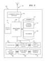
- FIG. 1shows a sensor device 105 .
- Sensor device 105may include a processing unit 110 and a memory 115 .
- Memory 115may include a sensor software module 120 and a database 125 . While executing on processing unit 110 , sensor software module 120 may perform processes for collecting and transmitting real-time sensor data.
- Sensor device 105may also include a communications package 130 that may include and antenna 135 and may be connected to processing unit 110 .
- Communications package 130may transmit real-time sensor data collected from sensor device 105 and may receive other data including control data.
- Communications package 130may communicate over a network (not shown.)
- the networkmay comprise, for example, a local area network (LAN) or a wide area network (WAN).
- LANlocal area network
- WANwide area network
- a network interface located at sensor device 105may be used to interconnect any other processor on the network.
- sensor device 105may include an internal or external modem (not shown) or other means for establishing communications over the WAN.
- data sent over the networkmay be encrypted to insure data security by using encryption/decryption techniques.
- a wireless communications systemmay be utilized as the network.
- Wirelessmay be defined as radio transmission via the airwaves.
- various other communication techniquescan be used to provide wireless transmission, including infrared line of sight, cellular, microwave, satellite, packet radio, and spread spectrum radio.
- sensor device 105may communicate across a wireless interface such as, for example, a cellular interface (e.g., general packet radio system (GPRS), enhanced data rates for global evolution (EDGE), global system for mobile communications (GSM)), a wireless local area network interface (e.g., WLAN, IEEE 802), a bluetooth interface, WiFi, WiMax, another RF communication interface, and/or an optical interface.
- GPRSgeneral packet radio system
- EDGEenhanced data rates for global evolution
- GSMglobal system for mobile communications
- WLANwireless local area network interface
- IEEE 802wireless local area network interface
- WiFiWiFi
- WiMaxanother RF communication interface
- optical interfaceanother RF communication interface
- Sensor device 105may include sensor transducers.
- the sensor transducersmay include, but are not limited to, a barometer 140 , a conductor temperature sensor 145 , an ambient temperature sensor 150 , a wind direction sensor 155 , a wind speed sensor 160 , and a humidity sensor 165 , all of which may collect and communicate sensor data to processing unit 110 .
- Barometer 140may collect sensor data comprising barometric pressure readings at a location where sensor device 105 is located.
- Ambient temperature sensor 150may collect sensor data comprising ambient temperature readings at the location where sensor device 105 is located.
- Wind direction sensor 155may collect sensor data comprising wind direction readings at the location where sensor device 105 is located.
- Wind speed sensor 160may collect sensor data comprising wind speed readings at the location where sensor device 105 is located.
- Humidity sensor 165may collect sensor data comprising humidity readings at the location where sensor device 105 is located.
- conductor temperature sensor 145may comprise a thermal couple coupled to the power line. Conductor temperature sensor 145 may collect sensor data comprising the temperature of a conductor comprising the power line.
- All elements within sensor device 105may be supplied with power from a power supply 170 . Again, because sensor device 105 may be in close proximity to the power line (e.g. coupled to the power line,) power supply 170 may scavenge power from the power line using a current transformer (CT,) for example.
- CTcurrent transformer
- FIG. 2shows an operating environment 200 for sensor device 105 consistent with embodiments of the invention.
- a power line 205may connect a first substation 210 and a second substation 215 .
- Power line 205may be tens or even hundreds of miles long and may pass through many different weather zones.
- RUS BULLETIN 1724E-200“DESIGN MANUAL FOR HIGH VOLTAGE TRANSMISSION LINES”, published by the Electric Staff Division, Rural Utilities Service, U.S. Department of Agriculture shows how power lines may be designed and is incorporated herein by reference.
- sensor devices 105may be placed on power line 205 .
- Sensor devices 105 in environment 200may include any one or more of a combination of the sensor transducers shown in FIG. 1 .
- Each of the sensor devices 105may collect sensor data at a location where the sensor device is located on power line 105 . After collection, each of the sensor devices 105 may transmit its collected sensor data to a central station 220 .
- the received sensor datamay be fed into a real-time rating software and/or supervisory control and data acquisition (SCADA) system 300 as shown in FIG. 3 .
- SCADAsupervisory control and data acquisition
- FIG. 3shows real-time rating software and/or supervisory control and data acquisition (SCADA) system 300 in more detail.
- SCADA system 300may include a processing unit 310 and a memory 315 .
- Memory 315may include a real-time rating software module 320 and a database 325 .
- sensor software module 320may perform, for example, processes for providing a real-time power line rating as described in greater detail below with respect to FIG. 4 .
- SCADA system 300may adapt power line 205 's ampacity rating to actual conditions experienced by power line 205 to increase power line 205 's conductor ampacity.
- SCADA system 300may provide a dynamic line rating for power line 205 in order to provide an increase in power line ampacity by considering a given conductor's heat-storage capacity in power line 205 . For example, if according to the sensor data the conductor's temperature is already at 98 degrees Fahrenheit with a low current load, SCADA system 300 may de-rate the conductor and suggest not loading it to its assumed full capacity. Moreover, if the conductor temperature according to the sensor data in at 15 degrees Fahrenheit with a high current load, SCADA system 300 may up-rate the conductor and suggest loading it above its assumed full capacity.
- SCADA system 300may use other data within the sensor data to accurately predict a rate of change in the conductor's temperature. With an accurately predicted rate of temperature change, SCADA system 300 can help power system operators, for example, to plan on how to load power line 205 latter in the day and take into consideration predicted dynamic line ratings for power line 205 .
- the sensor datamay be used to predict weather along power line 205 and thus predict a real-time rating for power line 205 hours or even days into the future.
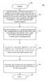
- FIG. 4is a flow chart setting forth the general stages involved in a method 400 consistent with embodiments of the invention for providing a real-time power line rating.
- Method 400may be implemented using SCADA system 300 as described in more detail above with respect to FIG. 3 . Ways to implement the stages of method 400 will be described in greater detail below.
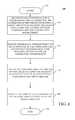
- Method 400may begin at starting block 405 and proceed to stage 410 where SCADA system 300 may receive design limitations for power line 205 having a conductor.
- the conductor of power line 205may have a design ampacity based upon the design limitations and assumed weather conditions for the conductor's environment.
- a power line operatore.g. an electric utility company
- Power line 205may be built to certain design limitations under assumed weather conditions.
- power line 205may be built to have a maximum amount of sag in certain worst case scenarios.
- Such worst case scenariosmay comprise the “hot curve” (i.e. maximum sag) condition.
- the hot curve conditionmay comprise, but is not limited to, maximum conductor operating temperature (e.g.
- power line 205may have the design ampacity based upon these design limitations and assumed weather conditions for the conductor's environment. Making these worst case scenarios helps the designer of power line 205 make sure that power line 205 is placed on tall enough structures and does not sag down too much and violate minimum vertical clearances for power line 205 set out by applicable safety codes (e.g. the National Electric Safety Code (NESC).) In reality, however, such worst case scenarios rarely exist.
- NSCNational Electric Safety Code
- step 410where SCADA system 300 receives the design limitations for power line 205 , method 400 may advance to stage 420 where SCADA system 300 may receive sensor data corresponding to the conductor of power line 205 .
- the sensor datamay provide real-time weather conditions for the conductor's environment.
- any number of sensor devices 105may be placed on power line 205 .
- Sensor devices 105 in environment 200may include any one or more of a combination of the sensor transducers shown in FIG. 1 .
- Each of the sensor devices 105may collect sensor data at a location where the sensor device is located on power line 105 . After collection, each of the sensor devices 105 may transmit its collected sensor data to a central station 220 where it is received by SCADA system 300 .
- the received sensor datamay comprise, but is not limited to: i) ambient temperature of the environment around the conductor at a point along power line 205 where a corresponding sensor device happens to be; ii) wind speed around the conductor at a point along power line 205 where the corresponding sensor device happens to be; iii) a solar radiation level (e.g. amount of cloudiness) at the conductor at a point along power line 205 where a corresponding sensor device happens to be; or iv) a temperature of the conductor itself at a point along power line 205 where a corresponding sensor device happens to be.
- the sensor datamay also include barometric pressure readings, wind direction, and humidity at the conductor at a point along power line 205 where a corresponding sensor device happens to be.
- the aforementionedare examples and the sensor data may comprise any data helpful for calculating real-time conductor ratings.
- SCADA system 300may calculate a dynamic ampacity for power line 205 based upon the received sensor data and the received design limitations for power line 205 . For example, if the sensor data is received at multiple points along power line 205 , like readings may be averaged. For example, conductor temperature at several points along power line may be averaged to provide an average conductor temperature. Or the reading that would produce the most conservative dynamically calculated ampacity for power line 205 may be used. For example, the highest conductor temperature at one of the several points along power line may be used.
- an objective of calculating the dynamic (e.g. real-time) ampacity for power line 205may be to calculate a more accurate ampacity for power line 205 not based on assumed or worst case environmental conditions, but rather on actual conditions for power line 205 's conductors. Notwithstanding, the calculated dynamic ampacity for power line 205 should not cause power line 205 's conductors to sag down too much and violate minimum vertical clearances for power line 205 set out by applicable safety codes. Also, the calculated dynamic ampacity for power line 205 should not cause power line 205 's conductors to become “annealed” or damaged in anyway.
- the objective of calculating the dynamic ampacity for power line 205is to consider the heat-storage capacity of the conductor. If the conductor gets too hot, minimum vertical clearances may be violated or the conductor may be damaged. At least two conditions contribute to the conductor's temperature, the amount of current running through the conductor and the environmental conditions. If the environmental conditions are favorable and contribute less heat to the conductor than assumed environmental conditions, then heat caused by current running through the conductor may be increased. Thus with these favorable environmental conditions, more current may be allowed to run through the conductor than can be allowed under the assumed environmental conditions while still maintaining minimum vertical clearances and not damaging the conductor. Consequently, by knowing the real-time environmental conditions, the ampacity of the conductor may be calculated dynamically thus increasing the current carried by power line 205 resulting in increasing the power delivered by power line 205 .
- method 400may proceed to stage 440 where SCADA system 300 may operate power line 205 according to the dynamic ampacity instead of the design ampacity.
- the design ampacitymay be based on environmental assumptions when power line 205 is designed. For example, by operating power line 205 according to the dynamic ampacity instead of the design ampacity, more power may be delivered between first substation 210 and second substation 215 without the expense of upgrading the size of power line 205 's conductors.
- method 400may then end at stage 450 .
- Embodiment of the present inventionmay, for example, be implemented using a memory, a processing unit, and other components. Any suitable combination of hardware, software, and/or firmware may be used to implement the memory, processing unit, or other components.
- the processing unitmay implement program modules.
- program modulesmay include routines, programs, components, data structures, and other types of structures that perform particular tasks or implement particular abstract data types.
- embodiments of the inventionmay be practiced with other computer system configurations, including hand-held devices, multiprocessor systems, microprocessor-based or programmable consumer electronics, minicomputers, mainframe computers, and the like.
- Embodiments of the inventionmay also be practiced in distributed computing environments where tasks are performed by remote processing devices that are linked through a communications network.
- program modulesmay be located in both local and remote memory storage devices.
- embodiments of the inventionmay be practiced in an electrical circuit comprising discrete electronic elements, packaged or integrated electronic chips containing logic gates, a circuit utilizing a microprocessor, or on a single chip containing electronic elements or microprocessors.
- Embodiments of the inventionmay also be practiced using other technologies capable of performing logical operations such as, for example, AND, OR, and NOT, including but not limited to mechanical, optical, fluidic, and quantum technologies.
- embodiments of the inventionmay be practiced within a general purpose computer or in any other circuits or systems.
- Embodiments of the inventionmay be implemented as a computer process (method), a computing system, or as an article of manufacture, such as a computer program product or computer readable media.
- the computer program productmay be a computer storage media readable by a computer system and encoding a computer program of instructions for executing a computer process.
- the computer program productmay also be a propagated signal on a carrier readable by a computing system and encoding a computer program of instructions for executing a computer process.
- the present inventionmay be embodied in hardware and/or in software (including firmware, resident software, micro-code, etc.).
- embodiments of the present inventionmay take the form of a computer program product on a computer-usable or computer-readable storage medium having computer-usable or computer-readable program code embodied in the medium for use by or in connection with an instruction execution system.
- a computer-usable or computer-readable mediummay be any medium that can contain, store, communicate, propagate, or transport the program for use by or in connection with the instruction execution system, apparatus, or device.
- the computer-usable or computer-readable mediummay be, for example but not limited to, an electronic, magnetic, optical, electromagnetic, infrared, or semiconductor system, apparatus, device, or propagation medium. More specific examples (a non-exhaustive list) of the computer-readable medium would include the following: an electrical connection having one or more wires, a portable computer diskette, a random access memory (RAM), a read-only memory (ROM), an erasable programmable read-only memory (EPROM or Flash memory), an optical fiber, and a portable compact disc read-only memory (CD-ROM).
- RAMrandom access memory
- ROMread-only memory
- EPROM or Flash memoryerasable programmable read-only memory
- CD-ROMportable compact disc read-only memory
- the computer-usable or computer-readable mediumcould even be paper or another suitable medium upon which the program is printed, as the program can be electronically captured, via, for instance, optical scanning of the paper or other medium, then compiled, interpreted, or otherwise processed in a suitable manner, if necessary, and then stored in a computer memory.
- Embodiments of the present inventionare described above with reference to block diagrams and/or operational illustrations of methods, systems, and computer program products according to embodiments of the invention. It is to be understood that the functions/acts noted in the blocks may occur out of the order noted in the operational illustrations. For example, two blocks shown in succession may in fact be executed substantially concurrently or the blocks may sometimes be executed in the reverse order, depending upon the functionality/acts involved.
Landscapes
- Engineering & Computer Science (AREA)
- Power Engineering (AREA)
- Physics & Mathematics (AREA)
- General Physics & Mathematics (AREA)
- Remote Monitoring And Control Of Power-Distribution Networks (AREA)
- Arrangements For Transmission Of Measured Signals (AREA)
- Management, Administration, Business Operations System, And Electronic Commerce (AREA)
Abstract
Description
Claims (20)
Priority Applications (1)
| Application Number | Priority Date | Filing Date | Title |
|---|---|---|---|
| US13/776,956US8744790B2 (en) | 2008-11-06 | 2013-02-26 | Real-time power line rating |
Applications Claiming Priority (3)
| Application Number | Priority Date | Filing Date | Title |
|---|---|---|---|
| US11181408P | 2008-11-06 | 2008-11-06 | |
| US12/612,728US8386198B2 (en) | 2008-11-06 | 2009-11-05 | Real-time power line rating |
| US13/776,956US8744790B2 (en) | 2008-11-06 | 2013-02-26 | Real-time power line rating |
Related Parent Applications (1)
| Application Number | Title | Priority Date | Filing Date |
|---|---|---|---|
| US12/612,728ContinuationUS8386198B2 (en) | 2008-11-06 | 2009-11-05 | Real-time power line rating |
Publications (2)
| Publication Number | Publication Date |
|---|---|
| US20130179079A1 US20130179079A1 (en) | 2013-07-11 |
| US8744790B2true US8744790B2 (en) | 2014-06-03 |
Family
ID=41683117
Family Applications (2)
| Application Number | Title | Priority Date | Filing Date |
|---|---|---|---|
| US12/612,728Expired - Fee RelatedUS8386198B2 (en) | 2008-11-06 | 2009-11-05 | Real-time power line rating |
| US13/776,956Expired - Fee RelatedUS8744790B2 (en) | 2008-11-06 | 2013-02-26 | Real-time power line rating |
Family Applications Before (1)
| Application Number | Title | Priority Date | Filing Date |
|---|---|---|---|
| US12/612,728Expired - Fee RelatedUS8386198B2 (en) | 2008-11-06 | 2009-11-05 | Real-time power line rating |
Country Status (4)
| Country | Link |
|---|---|
| US (2) | US8386198B2 (en) |
| CA (1) | CA2742854C (en) |
| MX (1) | MX2011004874A (en) |
| WO (1) | WO2010054072A1 (en) |
Cited By (5)
| Publication number | Priority date | Publication date | Assignee | Title |
|---|---|---|---|---|
| US20110238374A1 (en)* | 2010-03-23 | 2011-09-29 | Mark Lancaster | Power Line Maintenance Monitoring |
| CN104113083A (en)* | 2014-07-18 | 2014-10-22 | 国家电网公司 | New energy access and energy storage coordination control method under high permeability |
| US20160178681A1 (en)* | 2014-12-22 | 2016-06-23 | Université de Liège, Interface Entreprises - Université | Method and System for Determining the Thermal Power Line Rating |
| US10205307B2 (en) | 2010-03-23 | 2019-02-12 | Southwire Company, Llc | Power line maintenance monitoring |
| US11443155B2 (en)* | 2018-01-19 | 2022-09-13 | Lindsey Manufacturing Company | Insulator leakage current detector and method of detecting insulator leakage current |
Families Citing this family (212)
| Publication number | Priority date | Publication date | Assignee | Title |
|---|---|---|---|---|
| US7786894B2 (en)* | 2006-06-20 | 2010-08-31 | Battelle Energy Alliance, Llc | Methods, apparatus, and systems for monitoring transmission systems |
| CA2742854C (en) | 2008-11-06 | 2017-01-24 | Southwire Company | Real-time power line rating |
| US8437882B2 (en) | 2010-02-17 | 2013-05-07 | Inscope Energy, Llc | Managing power utilized within a local power network |
| DE102010035648A1 (en)* | 2010-08-27 | 2012-03-01 | Siemens Aktiengesellschaft | Sensor arrangement for overhead line facility, has sensor unit having microprocessor for receiving and for processing determined sensor data and communication device for transmission by microprocessor processed data to central office |
| US8738191B2 (en) | 2010-09-17 | 2014-05-27 | Sarantos K. Aivaliotis | System and method for power grid management |
| US8849472B2 (en) | 2011-02-02 | 2014-09-30 | Inscope Energy, Llc | Effectuating energization and deactivation of particular circuits through rules-based smart nodes |
| US20120253538A1 (en)* | 2011-03-28 | 2012-10-04 | Russell Raymond | Method and System for Generating and Optimizing the Capacity Ratings of an Electric Power System Facility |
| US9214832B2 (en)* | 2011-06-23 | 2015-12-15 | Siemens Industry, Inc. | Parallel electric service system and method using meter socket and load center combination |
| US9054531B2 (en)* | 2011-07-19 | 2015-06-09 | Carnegie Mellon University | General method for distributed line flow computing with local communications in meshed electric networks |
| US20130054162A1 (en) | 2011-08-31 | 2013-02-28 | Tollgrade Communications, Inc. | Methods and apparatus for determining conditions of power lines |
| DE102011083790A1 (en) | 2011-09-29 | 2013-04-04 | Bender Gmbh & Co. Kg | Insulation fault monitoring method with dynamic response |
| ES2522832T3 (en) | 2011-11-04 | 2014-11-18 | Rte Réseau De Transport D'electricité | Procedure and control device of a high voltage electric current transmission line |
| CN102565597B (en)* | 2012-02-14 | 2015-01-07 | 广东易事特电源股份有限公司 | Dynamic power transmission line capacity estimation method applying synchronized phasor technology |
| BR112014019973A2 (en)* | 2012-02-14 | 2017-06-13 | Tollgrade Communications Inc | transmission line management system |
| DE102012012401A1 (en) | 2012-06-25 | 2014-01-02 | Rwe Innogy Gmbh | METHOD FOR CURRENT CONTROL |
| US10009065B2 (en) | 2012-12-05 | 2018-06-26 | At&T Intellectual Property I, L.P. | Backhaul link for distributed antenna system |
| US9113347B2 (en) | 2012-12-05 | 2015-08-18 | At&T Intellectual Property I, Lp | Backhaul link for distributed antenna system |
| US9519014B2 (en) | 2012-12-06 | 2016-12-13 | Dynamic Engineers, Inc. | Systems and methods for calculating power transmission line capacity |
| US20140163884A1 (en) | 2012-12-10 | 2014-06-12 | Universite De Liege | Method and system for the determination of wind speeds and incident radiation parameters of overhead power lines |
| US9198500B2 (en) | 2012-12-21 | 2015-12-01 | Murray W. Davis | Portable self powered line mountable electric power line and environment parameter monitoring transmitting and receiving system |
| US20140244192A1 (en)* | 2013-02-25 | 2014-08-28 | Inscope Energy, Llc | System and method for providing monitoring of industrial equipment |
| US9525524B2 (en) | 2013-05-31 | 2016-12-20 | At&T Intellectual Property I, L.P. | Remote distributed antenna system |
| US9999038B2 (en) | 2013-05-31 | 2018-06-12 | At&T Intellectual Property I, L.P. | Remote distributed antenna system |
| US10128658B2 (en) | 2013-06-17 | 2018-11-13 | Carnegie Mellon University | Autonomous methods, systems, and software for self-adjusting generation, demand, and/or line flows/reactances to ensure feasible AC power flow |
| CN103426064A (en)* | 2013-08-21 | 2013-12-04 | 国家电网公司 | Background auxiliary analysis system for wireless temperature measurement of transformer substation power supply line |
| US8897697B1 (en) | 2013-11-06 | 2014-11-25 | At&T Intellectual Property I, Lp | Millimeter-wave surface-wave communications |
| US9209902B2 (en) | 2013-12-10 | 2015-12-08 | At&T Intellectual Property I, L.P. | Quasi-optical coupler |
| CN103926484B (en)* | 2014-03-14 | 2017-01-25 | 广东电网公司电力科学研究院 | Electric transmission line dynamic capacity increasing method based on circuit sag real-time measurement |
| US9972989B2 (en) | 2014-03-31 | 2018-05-15 | Aclara Technologies Llc | Optical voltage sensing for underground medium voltage wires |
| US9853445B2 (en) | 2014-05-02 | 2017-12-26 | Maple Microsystems Inc. | Method and system for monitoring an electrical power grid |
| US9692101B2 (en) | 2014-08-26 | 2017-06-27 | At&T Intellectual Property I, L.P. | Guided wave couplers for coupling electromagnetic waves between a waveguide surface and a surface of a wire |
| EP3186646B1 (en) | 2014-08-29 | 2021-10-20 | Aclara Technologies LLC | Power extraction for a medium voltage sensor using a capacitive voltage divider |
| US9768833B2 (en) | 2014-09-15 | 2017-09-19 | At&T Intellectual Property I, L.P. | Method and apparatus for sensing a condition in a transmission medium of electromagnetic waves |
| US10063280B2 (en) | 2014-09-17 | 2018-08-28 | At&T Intellectual Property I, L.P. | Monitoring and mitigating conditions in a communication network |
| US9628854B2 (en) | 2014-09-29 | 2017-04-18 | At&T Intellectual Property I, L.P. | Method and apparatus for distributing content in a communication network |
| US9615269B2 (en) | 2014-10-02 | 2017-04-04 | At&T Intellectual Property I, L.P. | Method and apparatus that provides fault tolerance in a communication network |
| US9685992B2 (en) | 2014-10-03 | 2017-06-20 | At&T Intellectual Property I, L.P. | Circuit panel network and methods thereof |
| US9503189B2 (en) | 2014-10-10 | 2016-11-22 | At&T Intellectual Property I, L.P. | Method and apparatus for arranging communication sessions in a communication system |
| US9973299B2 (en) | 2014-10-14 | 2018-05-15 | At&T Intellectual Property I, L.P. | Method and apparatus for adjusting a mode of communication in a communication network |
| US9762289B2 (en) | 2014-10-14 | 2017-09-12 | At&T Intellectual Property I, L.P. | Method and apparatus for transmitting or receiving signals in a transportation system |
| US9577306B2 (en) | 2014-10-21 | 2017-02-21 | At&T Intellectual Property I, L.P. | Guided-wave transmission device and methods for use therewith |
| US9780834B2 (en) | 2014-10-21 | 2017-10-03 | At&T Intellectual Property I, L.P. | Method and apparatus for transmitting electromagnetic waves |
| US9769020B2 (en) | 2014-10-21 | 2017-09-19 | At&T Intellectual Property I, L.P. | Method and apparatus for responding to events affecting communications in a communication network |
| US9653770B2 (en) | 2014-10-21 | 2017-05-16 | At&T Intellectual Property I, L.P. | Guided wave coupler, coupling module and methods for use therewith |
| US9312919B1 (en) | 2014-10-21 | 2016-04-12 | At&T Intellectual Property I, Lp | Transmission device with impairment compensation and methods for use therewith |
| US9520945B2 (en) | 2014-10-21 | 2016-12-13 | At&T Intellectual Property I, L.P. | Apparatus for providing communication services and methods thereof |
| US9564947B2 (en) | 2014-10-21 | 2017-02-07 | At&T Intellectual Property I, L.P. | Guided-wave transmission device with diversity and methods for use therewith |
| US9627768B2 (en) | 2014-10-21 | 2017-04-18 | At&T Intellectual Property I, L.P. | Guided-wave transmission device with non-fundamental mode propagation and methods for use therewith |
| US9544006B2 (en) | 2014-11-20 | 2017-01-10 | At&T Intellectual Property I, L.P. | Transmission device with mode division multiplexing and methods for use therewith |
| US9954287B2 (en) | 2014-11-20 | 2018-04-24 | At&T Intellectual Property I, L.P. | Apparatus for converting wireless signals and electromagnetic waves and methods thereof |
| US10340573B2 (en) | 2016-10-26 | 2019-07-02 | At&T Intellectual Property I, L.P. | Launcher with cylindrical coupling device and methods for use therewith |
| US10009067B2 (en) | 2014-12-04 | 2018-06-26 | At&T Intellectual Property I, L.P. | Method and apparatus for configuring a communication interface |
| US9680670B2 (en) | 2014-11-20 | 2017-06-13 | At&T Intellectual Property I, L.P. | Transmission device with channel equalization and control and methods for use therewith |
| US9742462B2 (en) | 2014-12-04 | 2017-08-22 | At&T Intellectual Property I, L.P. | Transmission medium and communication interfaces and methods for use therewith |
| US9654173B2 (en) | 2014-11-20 | 2017-05-16 | At&T Intellectual Property I, L.P. | Apparatus for powering a communication device and methods thereof |
| US9997819B2 (en) | 2015-06-09 | 2018-06-12 | At&T Intellectual Property I, L.P. | Transmission medium and method for facilitating propagation of electromagnetic waves via a core |
| US10243784B2 (en) | 2014-11-20 | 2019-03-26 | At&T Intellectual Property I, L.P. | System for generating topology information and methods thereof |
| US9461706B1 (en) | 2015-07-31 | 2016-10-04 | At&T Intellectual Property I, Lp | Method and apparatus for exchanging communication signals |
| US9800327B2 (en) | 2014-11-20 | 2017-10-24 | At&T Intellectual Property I, L.P. | Apparatus for controlling operations of a communication device and methods thereof |
| US10144036B2 (en) | 2015-01-30 | 2018-12-04 | At&T Intellectual Property I, L.P. | Method and apparatus for mitigating interference affecting a propagation of electromagnetic waves guided by a transmission medium |
| US9876570B2 (en) | 2015-02-20 | 2018-01-23 | At&T Intellectual Property I, Lp | Guided-wave transmission device with non-fundamental mode propagation and methods for use therewith |
| US9749013B2 (en) | 2015-03-17 | 2017-08-29 | At&T Intellectual Property I, L.P. | Method and apparatus for reducing attenuation of electromagnetic waves guided by a transmission medium |
| US9705561B2 (en) | 2015-04-24 | 2017-07-11 | At&T Intellectual Property I, L.P. | Directional coupling device and methods for use therewith |
| US10224981B2 (en) | 2015-04-24 | 2019-03-05 | At&T Intellectual Property I, Lp | Passive electrical coupling device and methods for use therewith |
| US9793954B2 (en) | 2015-04-28 | 2017-10-17 | At&T Intellectual Property I, L.P. | Magnetic coupling device and methods for use therewith |
| US9948354B2 (en) | 2015-04-28 | 2018-04-17 | At&T Intellectual Property I, L.P. | Magnetic coupling device with reflective plate and methods for use therewith |
| US9490869B1 (en) | 2015-05-14 | 2016-11-08 | At&T Intellectual Property I, L.P. | Transmission medium having multiple cores and methods for use therewith |
| US9871282B2 (en) | 2015-05-14 | 2018-01-16 | At&T Intellectual Property I, L.P. | At least one transmission medium having a dielectric surface that is covered at least in part by a second dielectric |
| US9748626B2 (en) | 2015-05-14 | 2017-08-29 | At&T Intellectual Property I, L.P. | Plurality of cables having different cross-sectional shapes which are bundled together to form a transmission medium |
| US10650940B2 (en) | 2015-05-15 | 2020-05-12 | At&T Intellectual Property I, L.P. | Transmission medium having a conductive material and methods for use therewith |
| US10679767B2 (en) | 2015-05-15 | 2020-06-09 | At&T Intellectual Property I, L.P. | Transmission medium having a conductive material and methods for use therewith |
| US9917341B2 (en) | 2015-05-27 | 2018-03-13 | At&T Intellectual Property I, L.P. | Apparatus and method for launching electromagnetic waves and for modifying radial dimensions of the propagating electromagnetic waves |
| US9866309B2 (en) | 2015-06-03 | 2018-01-09 | At&T Intellectual Property I, Lp | Host node device and methods for use therewith |
| US10812174B2 (en) | 2015-06-03 | 2020-10-20 | At&T Intellectual Property I, L.P. | Client node device and methods for use therewith |
| US10154493B2 (en) | 2015-06-03 | 2018-12-11 | At&T Intellectual Property I, L.P. | Network termination and methods for use therewith |
| US9912381B2 (en) | 2015-06-03 | 2018-03-06 | At&T Intellectual Property I, Lp | Network termination and methods for use therewith |
| US10103801B2 (en) | 2015-06-03 | 2018-10-16 | At&T Intellectual Property I, L.P. | Host node device and methods for use therewith |
| US10348391B2 (en) | 2015-06-03 | 2019-07-09 | At&T Intellectual Property I, L.P. | Client node device with frequency conversion and methods for use therewith |
| US9913139B2 (en) | 2015-06-09 | 2018-03-06 | At&T Intellectual Property I, L.P. | Signal fingerprinting for authentication of communicating devices |
| US9608692B2 (en) | 2015-06-11 | 2017-03-28 | At&T Intellectual Property I, L.P. | Repeater and methods for use therewith |
| US10142086B2 (en) | 2015-06-11 | 2018-11-27 | At&T Intellectual Property I, L.P. | Repeater and methods for use therewith |
| US9820146B2 (en) | 2015-06-12 | 2017-11-14 | At&T Intellectual Property I, L.P. | Method and apparatus for authentication and identity management of communicating devices |
| US9667317B2 (en) | 2015-06-15 | 2017-05-30 | At&T Intellectual Property I, L.P. | Method and apparatus for providing security using network traffic adjustments |
| US9509415B1 (en) | 2015-06-25 | 2016-11-29 | At&T Intellectual Property I, L.P. | Methods and apparatus for inducing a fundamental wave mode on a transmission medium |
| US9640850B2 (en) | 2015-06-25 | 2017-05-02 | At&T Intellectual Property I, L.P. | Methods and apparatus for inducing a non-fundamental wave mode on a transmission medium |
| US9865911B2 (en) | 2015-06-25 | 2018-01-09 | At&T Intellectual Property I, L.P. | Waveguide system for slot radiating first electromagnetic waves that are combined into a non-fundamental wave mode second electromagnetic wave on a transmission medium |
| US10170840B2 (en) | 2015-07-14 | 2019-01-01 | At&T Intellectual Property I, L.P. | Apparatus and methods for sending or receiving electromagnetic signals |
| US9847566B2 (en) | 2015-07-14 | 2017-12-19 | At&T Intellectual Property I, L.P. | Method and apparatus for adjusting a field of a signal to mitigate interference |
| US9628116B2 (en) | 2015-07-14 | 2017-04-18 | At&T Intellectual Property I, L.P. | Apparatus and methods for transmitting wireless signals |
| US10320586B2 (en) | 2015-07-14 | 2019-06-11 | At&T Intellectual Property I, L.P. | Apparatus and methods for generating non-interfering electromagnetic waves on an insulated transmission medium |
| US10033107B2 (en) | 2015-07-14 | 2018-07-24 | At&T Intellectual Property I, L.P. | Method and apparatus for coupling an antenna to a device |
| US10148016B2 (en) | 2015-07-14 | 2018-12-04 | At&T Intellectual Property I, L.P. | Apparatus and methods for communicating utilizing an antenna array |
| US10341142B2 (en) | 2015-07-14 | 2019-07-02 | At&T Intellectual Property I, L.P. | Apparatus and methods for generating non-interfering electromagnetic waves on an uninsulated conductor |
| US9722318B2 (en) | 2015-07-14 | 2017-08-01 | At&T Intellectual Property I, L.P. | Method and apparatus for coupling an antenna to a device |
| US10205655B2 (en) | 2015-07-14 | 2019-02-12 | At&T Intellectual Property I, L.P. | Apparatus and methods for communicating utilizing an antenna array and multiple communication paths |
| US9882257B2 (en) | 2015-07-14 | 2018-01-30 | At&T Intellectual Property I, L.P. | Method and apparatus for launching a wave mode that mitigates interference |
| US10044409B2 (en) | 2015-07-14 | 2018-08-07 | At&T Intellectual Property I, L.P. | Transmission medium and methods for use therewith |
| US10033108B2 (en) | 2015-07-14 | 2018-07-24 | At&T Intellectual Property I, L.P. | Apparatus and methods for generating an electromagnetic wave having a wave mode that mitigates interference |
| US9853342B2 (en) | 2015-07-14 | 2017-12-26 | At&T Intellectual Property I, L.P. | Dielectric transmission medium connector and methods for use therewith |
| US9836957B2 (en) | 2015-07-14 | 2017-12-05 | At&T Intellectual Property I, L.P. | Method and apparatus for communicating with premises equipment |
| US9793951B2 (en) | 2015-07-15 | 2017-10-17 | At&T Intellectual Property I, L.P. | Method and apparatus for launching a wave mode that mitigates interference |
| US9608740B2 (en) | 2015-07-15 | 2017-03-28 | At&T Intellectual Property I, L.P. | Method and apparatus for launching a wave mode that mitigates interference |
| US10090606B2 (en) | 2015-07-15 | 2018-10-02 | At&T Intellectual Property I, L.P. | Antenna system with dielectric array and methods for use therewith |
| US9871283B2 (en) | 2015-07-23 | 2018-01-16 | At&T Intellectual Property I, Lp | Transmission medium having a dielectric core comprised of plural members connected by a ball and socket configuration |
| US10784670B2 (en) | 2015-07-23 | 2020-09-22 | At&T Intellectual Property I, L.P. | Antenna support for aligning an antenna |
| US9912027B2 (en) | 2015-07-23 | 2018-03-06 | At&T Intellectual Property I, L.P. | Method and apparatus for exchanging communication signals |
| US9948333B2 (en) | 2015-07-23 | 2018-04-17 | At&T Intellectual Property I, L.P. | Method and apparatus for wireless communications to mitigate interference |
| US9749053B2 (en) | 2015-07-23 | 2017-08-29 | At&T Intellectual Property I, L.P. | Node device, repeater and methods for use therewith |
| US10020587B2 (en) | 2015-07-31 | 2018-07-10 | At&T Intellectual Property I, L.P. | Radial antenna and methods for use therewith |
| US9967173B2 (en) | 2015-07-31 | 2018-05-08 | At&T Intellectual Property I, L.P. | Method and apparatus for authentication and identity management of communicating devices |
| US9735833B2 (en) | 2015-07-31 | 2017-08-15 | At&T Intellectual Property I, L.P. | Method and apparatus for communications management in a neighborhood network |
| CN105118242B (en)* | 2015-08-19 | 2017-03-15 | 国网浙江省电力公司湖州供电公司 | A kind of temperature and humidity intelligent warning device based on SCADA |
| CN105115543B (en)* | 2015-08-19 | 2017-03-15 | 国网浙江省电力公司湖州供电公司 | A kind of temperature and humidity intelligent alarm device based on SCADA |
| US9904535B2 (en) | 2015-09-14 | 2018-02-27 | At&T Intellectual Property I, L.P. | Method and apparatus for distributing software |
| US10009063B2 (en) | 2015-09-16 | 2018-06-26 | At&T Intellectual Property I, L.P. | Method and apparatus for use with a radio distributed antenna system having an out-of-band reference signal |
| US10136434B2 (en) | 2015-09-16 | 2018-11-20 | At&T Intellectual Property I, L.P. | Method and apparatus for use with a radio distributed antenna system having an ultra-wideband control channel |
| US9705571B2 (en) | 2015-09-16 | 2017-07-11 | At&T Intellectual Property I, L.P. | Method and apparatus for use with a radio distributed antenna system |
| US10079661B2 (en) | 2015-09-16 | 2018-09-18 | At&T Intellectual Property I, L.P. | Method and apparatus for use with a radio distributed antenna system having a clock reference |
| US10009901B2 (en) | 2015-09-16 | 2018-06-26 | At&T Intellectual Property I, L.P. | Method, apparatus, and computer-readable storage medium for managing utilization of wireless resources between base stations |
| US10051629B2 (en) | 2015-09-16 | 2018-08-14 | At&T Intellectual Property I, L.P. | Method and apparatus for use with a radio distributed antenna system having an in-band reference signal |
| US9769128B2 (en) | 2015-09-28 | 2017-09-19 | At&T Intellectual Property I, L.P. | Method and apparatus for encryption of communications over a network |
| US9729197B2 (en) | 2015-10-01 | 2017-08-08 | At&T Intellectual Property I, L.P. | Method and apparatus for communicating network management traffic over a network |
| US9876264B2 (en) | 2015-10-02 | 2018-01-23 | At&T Intellectual Property I, Lp | Communication system, guided wave switch and methods for use therewith |
| US9882277B2 (en) | 2015-10-02 | 2018-01-30 | At&T Intellectual Property I, Lp | Communication device and antenna assembly with actuated gimbal mount |
| US10074890B2 (en) | 2015-10-02 | 2018-09-11 | At&T Intellectual Property I, L.P. | Communication device and antenna with integrated light assembly |
| CN105162414B (en)* | 2015-10-09 | 2016-08-24 | 浙江嘉科新能源科技有限公司 | Photovoltaic power station power prediction system based on time sequence database platform |
| US10355367B2 (en) | 2015-10-16 | 2019-07-16 | At&T Intellectual Property I, L.P. | Antenna structure for exchanging wireless signals |
| US10051483B2 (en) | 2015-10-16 | 2018-08-14 | At&T Intellectual Property I, L.P. | Method and apparatus for directing wireless signals |
| US10665942B2 (en) | 2015-10-16 | 2020-05-26 | At&T Intellectual Property I, L.P. | Method and apparatus for adjusting wireless communications |
| ES2569431B1 (en)* | 2015-12-29 | 2017-02-23 | Universidad De Cantabria | Methodology for the calculation and prediction of ampacity in overhead power lines, according to the choice of critical sites |
| US9912419B1 (en) | 2016-08-24 | 2018-03-06 | At&T Intellectual Property I, L.P. | Method and apparatus for managing a fault in a distributed antenna system |
| US9860075B1 (en) | 2016-08-26 | 2018-01-02 | At&T Intellectual Property I, L.P. | Method and communication node for broadband distribution |
| US10291311B2 (en) | 2016-09-09 | 2019-05-14 | At&T Intellectual Property I, L.P. | Method and apparatus for mitigating a fault in a distributed antenna system |
| US11032819B2 (en) | 2016-09-15 | 2021-06-08 | At&T Intellectual Property I, L.P. | Method and apparatus for use with a radio distributed antenna system having a control channel reference signal |
| CN106231645B (en)* | 2016-09-22 | 2017-08-08 | 国家电网公司 | The wireless sensor network data transmission method of distribution line status monitoring |
| US10340600B2 (en) | 2016-10-18 | 2019-07-02 | At&T Intellectual Property I, L.P. | Apparatus and methods for launching guided waves via plural waveguide systems |
| US10135147B2 (en) | 2016-10-18 | 2018-11-20 | At&T Intellectual Property I, L.P. | Apparatus and methods for launching guided waves via an antenna |
| US10135146B2 (en) | 2016-10-18 | 2018-11-20 | At&T Intellectual Property I, L.P. | Apparatus and methods for launching guided waves via circuits |
| US10811767B2 (en) | 2016-10-21 | 2020-10-20 | At&T Intellectual Property I, L.P. | System and dielectric antenna with convex dielectric radome |
| US9991580B2 (en) | 2016-10-21 | 2018-06-05 | At&T Intellectual Property I, L.P. | Launcher and coupling system for guided wave mode cancellation |
| US10374316B2 (en) | 2016-10-21 | 2019-08-06 | At&T Intellectual Property I, L.P. | System and dielectric antenna with non-uniform dielectric |
| US9876605B1 (en) | 2016-10-21 | 2018-01-23 | At&T Intellectual Property I, L.P. | Launcher and coupling system to support desired guided wave mode |
| US10312567B2 (en) | 2016-10-26 | 2019-06-04 | At&T Intellectual Property I, L.P. | Launcher with planar strip antenna and methods for use therewith |
| US10498044B2 (en) | 2016-11-03 | 2019-12-03 | At&T Intellectual Property I, L.P. | Apparatus for configuring a surface of an antenna |
| US10291334B2 (en) | 2016-11-03 | 2019-05-14 | At&T Intellectual Property I, L.P. | System for detecting a fault in a communication system |
| US10225025B2 (en) | 2016-11-03 | 2019-03-05 | At&T Intellectual Property I, L.P. | Method and apparatus for detecting a fault in a communication system |
| US10224634B2 (en) | 2016-11-03 | 2019-03-05 | At&T Intellectual Property I, L.P. | Methods and apparatus for adjusting an operational characteristic of an antenna |
| US10535928B2 (en) | 2016-11-23 | 2020-01-14 | At&T Intellectual Property I, L.P. | Antenna system and methods for use therewith |
| US10340601B2 (en) | 2016-11-23 | 2019-07-02 | At&T Intellectual Property I, L.P. | Multi-antenna system and methods for use therewith |
| US10340603B2 (en) | 2016-11-23 | 2019-07-02 | At&T Intellectual Property I, L.P. | Antenna system having shielded structural configurations for assembly |
| US10090594B2 (en) | 2016-11-23 | 2018-10-02 | At&T Intellectual Property I, L.P. | Antenna system having structural configurations for assembly |
| US10178445B2 (en) | 2016-11-23 | 2019-01-08 | At&T Intellectual Property I, L.P. | Methods, devices, and systems for load balancing between a plurality of waveguides |
| US10305190B2 (en) | 2016-12-01 | 2019-05-28 | At&T Intellectual Property I, L.P. | Reflecting dielectric antenna system and methods for use therewith |
| US10361489B2 (en) | 2016-12-01 | 2019-07-23 | At&T Intellectual Property I, L.P. | Dielectric dish antenna system and methods for use therewith |
| US10637149B2 (en) | 2016-12-06 | 2020-04-28 | At&T Intellectual Property I, L.P. | Injection molded dielectric antenna and methods for use therewith |
| US10439675B2 (en) | 2016-12-06 | 2019-10-08 | At&T Intellectual Property I, L.P. | Method and apparatus for repeating guided wave communication signals |
| US10135145B2 (en) | 2016-12-06 | 2018-11-20 | At&T Intellectual Property I, L.P. | Apparatus and methods for generating an electromagnetic wave along a transmission medium |
| US10382976B2 (en) | 2016-12-06 | 2019-08-13 | At&T Intellectual Property I, L.P. | Method and apparatus for managing wireless communications based on communication paths and network device positions |
| US10020844B2 (en) | 2016-12-06 | 2018-07-10 | T&T Intellectual Property I, L.P. | Method and apparatus for broadcast communication via guided waves |
| US9927517B1 (en) | 2016-12-06 | 2018-03-27 | At&T Intellectual Property I, L.P. | Apparatus and methods for sensing rainfall |
| US10755542B2 (en) | 2016-12-06 | 2020-08-25 | At&T Intellectual Property I, L.P. | Method and apparatus for surveillance via guided wave communication |
| US10727599B2 (en) | 2016-12-06 | 2020-07-28 | At&T Intellectual Property I, L.P. | Launcher with slot antenna and methods for use therewith |
| US10694379B2 (en) | 2016-12-06 | 2020-06-23 | At&T Intellectual Property I, L.P. | Waveguide system with device-based authentication and methods for use therewith |
| US10326494B2 (en) | 2016-12-06 | 2019-06-18 | At&T Intellectual Property I, L.P. | Apparatus for measurement de-embedding and methods for use therewith |
| US10819035B2 (en) | 2016-12-06 | 2020-10-27 | At&T Intellectual Property I, L.P. | Launcher with helical antenna and methods for use therewith |
| US10547348B2 (en) | 2016-12-07 | 2020-01-28 | At&T Intellectual Property I, L.P. | Method and apparatus for switching transmission mediums in a communication system |
| US10027397B2 (en) | 2016-12-07 | 2018-07-17 | At&T Intellectual Property I, L.P. | Distributed antenna system and methods for use therewith |
| US10359749B2 (en) | 2016-12-07 | 2019-07-23 | At&T Intellectual Property I, L.P. | Method and apparatus for utilities management via guided wave communication |
| US10139820B2 (en) | 2016-12-07 | 2018-11-27 | At&T Intellectual Property I, L.P. | Method and apparatus for deploying equipment of a communication system |
| US10446936B2 (en) | 2016-12-07 | 2019-10-15 | At&T Intellectual Property I, L.P. | Multi-feed dielectric antenna system and methods for use therewith |
| US10243270B2 (en) | 2016-12-07 | 2019-03-26 | At&T Intellectual Property I, L.P. | Beam adaptive multi-feed dielectric antenna system and methods for use therewith |
| US9893795B1 (en) | 2016-12-07 | 2018-02-13 | At&T Intellectual Property I, Lp | Method and repeater for broadband distribution |
| US10168695B2 (en) | 2016-12-07 | 2019-01-01 | At&T Intellectual Property I, L.P. | Method and apparatus for controlling an unmanned aircraft |
| US10389029B2 (en) | 2016-12-07 | 2019-08-20 | At&T Intellectual Property I, L.P. | Multi-feed dielectric antenna system with core selection and methods for use therewith |
| US9998870B1 (en) | 2016-12-08 | 2018-06-12 | At&T Intellectual Property I, L.P. | Method and apparatus for proximity sensing |
| US10601494B2 (en) | 2016-12-08 | 2020-03-24 | At&T Intellectual Property I, L.P. | Dual-band communication device and method for use therewith |
| US10411356B2 (en) | 2016-12-08 | 2019-09-10 | At&T Intellectual Property I, L.P. | Apparatus and methods for selectively targeting communication devices with an antenna array |
| US10938108B2 (en) | 2016-12-08 | 2021-03-02 | At&T Intellectual Property I, L.P. | Frequency selective multi-feed dielectric antenna system and methods for use therewith |
| US10530505B2 (en) | 2016-12-08 | 2020-01-07 | At&T Intellectual Property I, L.P. | Apparatus and methods for launching electromagnetic waves along a transmission medium |
| US10326689B2 (en) | 2016-12-08 | 2019-06-18 | At&T Intellectual Property I, L.P. | Method and system for providing alternative communication paths |
| US10777873B2 (en) | 2016-12-08 | 2020-09-15 | At&T Intellectual Property I, L.P. | Method and apparatus for mounting network devices |
| US10389037B2 (en) | 2016-12-08 | 2019-08-20 | At&T Intellectual Property I, L.P. | Apparatus and methods for selecting sections of an antenna array and use therewith |
| US10916969B2 (en) | 2016-12-08 | 2021-02-09 | At&T Intellectual Property I, L.P. | Method and apparatus for providing power using an inductive coupling |
| US10103422B2 (en) | 2016-12-08 | 2018-10-16 | At&T Intellectual Property I, L.P. | Method and apparatus for mounting network devices |
| US9911020B1 (en) | 2016-12-08 | 2018-03-06 | At&T Intellectual Property I, L.P. | Method and apparatus for tracking via a radio frequency identification device |
| US10069535B2 (en) | 2016-12-08 | 2018-09-04 | At&T Intellectual Property I, L.P. | Apparatus and methods for launching electromagnetic waves having a certain electric field structure |
| US9838896B1 (en) | 2016-12-09 | 2017-12-05 | At&T Intellectual Property I, L.P. | Method and apparatus for assessing network coverage |
| US10340983B2 (en) | 2016-12-09 | 2019-07-02 | At&T Intellectual Property I, L.P. | Method and apparatus for surveying remote sites via guided wave communications |
| US10264586B2 (en) | 2016-12-09 | 2019-04-16 | At&T Mobility Ii Llc | Cloud-based packet controller and methods for use therewith |
| US9973940B1 (en) | 2017-02-27 | 2018-05-15 | At&T Intellectual Property I, L.P. | Apparatus and methods for dynamic impedance matching of a guided wave launcher |
| WO2018160924A1 (en) | 2017-03-02 | 2018-09-07 | Rosemount Inc. | Trending functions for partial discharge |
| US10298293B2 (en) | 2017-03-13 | 2019-05-21 | At&T Intellectual Property I, L.P. | Apparatus of communication utilizing wireless network devices |
| US10637239B2 (en)* | 2017-10-13 | 2020-04-28 | Honeywell International Inc. | Utility network monitoring device |
| US11067639B2 (en) | 2017-11-03 | 2021-07-20 | Rosemount Inc. | Trending functions for predicting the health of electric power assets |
| CN108152531B (en)* | 2017-11-21 | 2019-10-11 | 东南大学 | A capacitive three-dimensional wind speed and direction sensor |
| US10794736B2 (en) | 2018-03-15 | 2020-10-06 | Rosemount Inc. | Elimination of floating potential when mounting wireless sensors to insulated conductors |
| US11181570B2 (en) | 2018-06-15 | 2021-11-23 | Rosemount Inc. | Partial discharge synthesizer |
| US10833531B2 (en) | 2018-10-02 | 2020-11-10 | Rosemount Inc. | Electric power generation or distribution asset monitoring |
| IT201800011059A1 (en)* | 2018-12-13 | 2020-06-13 | C R M Consulenze Ricerche Mecc S R L | Wind-induced motion or vibration monitoring system in at least one suspended cable, in particular an overhead cable conducting a transmission or distribution power line; relative method and relative sensor |
| BR112021012093A2 (en) | 2018-12-21 | 2021-08-31 | 3M Innovative Properties Company | ELECTRIC POWER CABLE PREPARATION SYSTEM |
| WO2020132526A1 (en) | 2018-12-21 | 2020-06-25 | 3M Innovative Properties Company | Electrical power cable preparation device |
| WO2021025947A1 (en)* | 2019-08-02 | 2021-02-11 | 3M Innovative Properties Company | Multichannel electrical power grid monitoring system for detecting and analyzing sensor installation and configuration errors |
| CN110601254B (en)* | 2019-08-23 | 2021-06-01 | 国网福建省电力有限公司 | An optimal configuration method and system for wind farm energy storage considering dynamic current-carrying characteristics |
| US11313895B2 (en) | 2019-09-24 | 2022-04-26 | Rosemount Inc. | Antenna connectivity with shielded twisted pair cable |
| EP3839989B1 (en)* | 2019-12-19 | 2024-08-21 | HSP Hochspannungsgeräte GmbH | Air throttling coil with temperature sensing system |
| BR112022012733A2 (en) | 2019-12-26 | 2022-09-06 | 3M Innovative Properties Co | AUTOMATED CABLE PREPARATION WITH MODULAR SYSTEM |
| EP4085265A1 (en) | 2019-12-31 | 2022-11-09 | 3M Innovative Properties Company | Local partial discharge monitoring |
| WO2022097178A1 (en)* | 2020-11-05 | 2022-05-12 | Laki Power EHF. | Surveillance and weather stations on overhead power lines |
| CN113109640B (en)* | 2021-03-04 | 2022-05-17 | 国网浙江省电力有限公司嘉兴供电公司 | Power line intelligent dynamic capacity increasing system and method based on pre-simulation |
| CN112946399B (en)* | 2021-03-04 | 2022-04-29 | 国网浙江省电力有限公司嘉兴供电公司 | A method of dynamic line capacity expansion based on big data technology |
| CN113887061B (en)* | 2021-10-14 | 2024-06-28 | 上海电力大学 | Power transmission line dynamic capacity-increasing system considering multi-factor correction |
| WO2024211858A1 (en)* | 2023-04-05 | 2024-10-10 | Ctc Global Corporation | Systems and methods for operating an overhead electrical line |
Citations (98)
| Publication number | Priority date | Publication date | Assignee | Title |
|---|---|---|---|---|
| US3771356A (en) | 1972-03-14 | 1973-11-13 | Saskatchewan Power Corp | Vibration measuring assemblies for energized and non-energized power line vibration measurements |
| US4384289A (en) | 1981-01-23 | 1983-05-17 | General Electric Company | Transponder unit for measuring temperature and current on live transmission lines |
| US4420752A (en) | 1978-03-20 | 1983-12-13 | Murray W. Davis | Real-time parameter sensor-transmitter |
| US4689752A (en) | 1983-04-13 | 1987-08-25 | Niagara Mohawk Power Corporation | System and apparatus for monitoring and control of a bulk electric power delivery system |
| US4728887A (en)* | 1984-06-22 | 1988-03-01 | Davis Murray W | System for rating electric power transmission lines and equipment |
| US4777381A (en) | 1983-04-13 | 1988-10-11 | Fernandes Roosevelt A | Electrical power line and substation monitoring apparatus and systems |
| US4786862A (en) | 1986-06-09 | 1988-11-22 | Niagara Mohawk Power Corporation | Watchdog circuit for transmission line sensor module |
| US4794327A (en) | 1983-04-13 | 1988-12-27 | Fernandes Roosevelt A | Electrical parameter sensing module for mounting on and removal from an energized high voltage power conductor |
| US4796027A (en) | 1983-04-13 | 1989-01-03 | Niagara Mohawk Power Corporation | Apparatus for data transmission from multiple sources on a single channel |
| US4806855A (en) | 1984-06-22 | 1989-02-21 | Davis Murray W | System for rating electric power transmission lines and equipment |
| US4808917A (en) | 1983-04-13 | 1989-02-28 | Niagara Mohawk Power Corporation | Transmission line sensor apparatus operable with near zero current line conditions |
| US4821138A (en) | 1986-05-23 | 1989-04-11 | Sumitomo Electric Industries, Ltd. | Monitoring device for overhead power transmission system |
| US4827272A (en) | 1984-06-04 | 1989-05-02 | Davis Murray W | Overhead power line clamp and antenna |
| US4829298A (en) | 1983-04-13 | 1989-05-09 | Fernandes Roosevelt A | Electrical power line monitoring systems, including harmonic value measurements and relaying communications |
| US4886980A (en) | 1985-11-05 | 1989-12-12 | Niagara Mohawk Power Corporation | Transmission line sensor apparatus operable with near zero current line conditions |
| US4891576A (en) | 1988-08-22 | 1990-01-02 | The United States Of America As Represented By The Secretary Of The Interior | Ground-based transmission line conductor motion sensor |
| US4894785A (en) | 1987-09-18 | 1990-01-16 | Fernandes Roosevelt A | High voltage conductor mounted line powered monitoring system |
| US4904996A (en) | 1988-01-19 | 1990-02-27 | Fernandes Roosevelt A | Line-mounted, movable, power line monitoring system |
| US5006846A (en) | 1987-11-12 | 1991-04-09 | Granville J Michael | Power transmission line monitoring system |
| US5029101A (en) | 1987-09-18 | 1991-07-02 | Fernandes Roosevelt A | High voltage conductor mounted line powered monitoring system |
| US5107447A (en) | 1988-05-16 | 1992-04-21 | Hitachi, Ltd. | Abnormality diagnosing system and method for a high voltage power apparatus |
| US5121644A (en) | 1990-02-14 | 1992-06-16 | Stc Plc | Deploying cables in pipelines |
| US5140257A (en) | 1984-06-22 | 1992-08-18 | Davis Murray W | System for rating electric power transmission lines and equipment |
| US5214595A (en) | 1988-05-16 | 1993-05-25 | Hitachi, Ltd. | Abnormality diagnosing system and method for a high voltage power apparatus |
| US5235681A (en) | 1988-06-22 | 1993-08-10 | Hitachi, Ltd. | Image filing system for protecting partial regions of image data of a document |
| US5235861A (en) | 1991-05-03 | 1993-08-17 | Seppa Tapani O | Power transmission line monitoring system |
| US5341088A (en) | 1984-06-22 | 1994-08-23 | Davis Murray W | System for rating electric power transmission lines and equipment |
| US5397983A (en) | 1993-01-22 | 1995-03-14 | Consolidated Edison Company Of New York, Inc. | Vibration based deenergized cable detector and method |
| WO1995029553A1 (en) | 1994-04-25 | 1995-11-02 | Foster-Miller Inc. | Self-powered powerline sensor |
| WO1995035478A1 (en) | 1994-06-20 | 1995-12-28 | Hafslund Nycomed A.S | Apparatus for monitoring overhead electric lines |
| US5517864A (en) | 1994-05-31 | 1996-05-21 | Seppa; Tapani O. | Power transmission line tension monitoring system |
| US5559430A (en) | 1994-07-27 | 1996-09-24 | Seppa; Tapani O. | Net radiation sensor |
| US5565783A (en) | 1994-09-29 | 1996-10-15 | Pacific Gas And Electric Company | Fault sensor device with radio transceiver |
| WO1998020468A1 (en) | 1996-11-01 | 1998-05-14 | Foster-Miller, Inc. | Modular core, self-powered powerline sensor |
| US5918288A (en) | 1997-03-11 | 1999-06-29 | Seppa; Tapani O | Transmission line load cell protection system |
| US5933355A (en)* | 1995-05-04 | 1999-08-03 | Deb; Anjan Kumar | Object oriented expert power line ampacity system |
| US6097298A (en) | 1998-02-13 | 2000-08-01 | Ecsi Corporation | Apparatus and method of monitoring a power transmission line |
| WO2000062317A1 (en) | 1999-04-08 | 2000-10-19 | Doble Engineering Company | Monitoring leakage currents from high-voltage devices |
| US6205867B1 (en) | 1998-10-07 | 2001-03-27 | American Electric Power, Inc. | Power line sag monitor |
| WO2002037925A2 (en) | 2000-10-10 | 2002-05-16 | Sempra Fiber Links | Methods and systems for installing cable and conduit in pipelines |
| US20030014199A1 (en) | 2001-07-12 | 2003-01-16 | Patrick Toomey | System and methods for detecting fault in structure |
| US6677743B1 (en) | 1999-03-05 | 2004-01-13 | Foster-Miller, Inc. | High voltage powerline sensor with a plurality of voltage sensing devices |
| EP1385013A1 (en) | 2002-07-22 | 2004-01-28 | General Electric Company | Multifunction intelligent electronic device and method |
| US6727604B2 (en) | 1998-12-04 | 2004-04-27 | Hydro-Quebec | Switching apparatus and method for a segment of an electric power line |
| WO2004038891A2 (en) | 2002-10-07 | 2004-05-06 | Protura As | System and device for monitoring an overhead power line |
| US6735549B2 (en) | 2001-03-28 | 2004-05-11 | Westinghouse Electric Co. Llc | Predictive maintenance display system |
| US6776572B2 (en) | 2001-07-18 | 2004-08-17 | Ferag Ag | Method and device for stacking flat articles |
| US6799080B1 (en) | 2003-06-12 | 2004-09-28 | The Boc Group, Inc. | Configurable PLC and SCADA-based control system |
| US6873746B2 (en) | 2001-08-02 | 2005-03-29 | Electric Power Research Institute, Inc. | Apparatus and method for monitoring a cable |
| WO2005059491A2 (en) | 2003-12-11 | 2005-06-30 | Joslyn Hi-Voltage Corp. | Transmission/distribution line fault indicator with remote polling and current sensing and reporting capability |
| US7006524B2 (en) | 2002-06-12 | 2006-02-28 | Natis Communications Corporation | Modular SCADA communication apparatus and system for using same |
| WO2006085804A1 (en) | 2005-02-14 | 2006-08-17 | Abb Research Ltd | Line inspection |
| US7103511B2 (en) | 1998-10-14 | 2006-09-05 | Statsignal Ipc, Llc | Wireless communication networks for providing remote monitoring of devices |
| EP1703428A2 (en) | 2005-03-18 | 2006-09-20 | ABB PATENT GmbH | System and method for process data simulation |
| US7136725B1 (en) | 2001-06-21 | 2006-11-14 | Paciorek Ronald R | Load shed notification method, product, and apparatus |
| US20060265175A1 (en) | 2005-05-09 | 2006-11-23 | Manuchehr Shimohamadi | Low-cost multi-span conductor temperature measurement system |
| US20070038396A1 (en)* | 2001-12-21 | 2007-02-15 | Abb Schweiz Ag | Parameter estimation for and use of a thermal model of a power line |
| US7188997B2 (en) | 2005-01-21 | 2007-03-13 | Eaton Corporation | Apparatus and method for detecting hot spots in an electric power conductor |
| WO2007031435A1 (en) | 2005-09-16 | 2007-03-22 | Universite De Liege | Device, system and method for real-time monitoring of overhead power lines |
| US7274186B2 (en) | 2004-01-16 | 2007-09-25 | Fieldmetrics, Inc | Temperature compensated and self-calibrated current sensor |
| US7282944B2 (en) | 2003-07-25 | 2007-10-16 | Power Measurement, Ltd. | Body capacitance electric field powered device for high voltage lines |
| WO2007134022A2 (en) | 2006-05-11 | 2007-11-22 | Underground Systems, Inc. | A power line temperature and sag monitor system |
| US7310948B2 (en) | 2002-10-09 | 2007-12-25 | Manucheher Shirmohamadi | De-icer for suspended overhead lines |
| WO2007149668A2 (en) | 2006-06-20 | 2007-12-27 | Battelle Energy Alliance, Llc | Methods, apparatus, and systems for monitoring transmission systems |
| US7336202B2 (en) | 2001-04-17 | 2008-02-26 | Sanyo Electric Co., Ltd. | Temperature monitoring device |
| US20080077336A1 (en) | 2006-09-25 | 2008-03-27 | Roosevelt Fernandes | Power line universal monitor |
| US20080189061A1 (en) | 2007-02-05 | 2008-08-07 | Abb Research Ltd. | Real-time power-line sag monitoring using time-synchronized power system measurements |
| WO2008097458A1 (en) | 2007-02-05 | 2008-08-14 | Abb Research Ltd. | Power-line sag calculation by way of power-system state estimation |
| US7430932B2 (en) | 2002-10-31 | 2008-10-07 | Boris Iosifovitch Mekhanoshin | Device for telemonitoring the state of aerial power lines(variants) |
| US20090015239A1 (en) | 2007-03-01 | 2009-01-15 | Georgiou George E | Transmission Line Sensor |
| US7504819B2 (en) | 2004-07-21 | 2009-03-17 | Underground Systems, Inc. | Dynamic line rating system with real-time tracking of conductor creep to establish the maximum allowable conductor loading as limited by clearance |
| US20090115426A1 (en) | 2007-11-02 | 2009-05-07 | Cooper Technologies Company | Faulted circuit indicator apparatus with transmission line state display and method of use thereof |
| WO2009058955A1 (en) | 2007-11-02 | 2009-05-07 | Cooper Technologies Company | Faulted circuit indicator apparatus with transmission line state display and method of use thereof |
| US7575371B1 (en) | 2004-11-11 | 2009-08-18 | Fieldmetrics, Inc | Temperature sensor and extensometer |
| US20090284249A1 (en) | 2006-09-08 | 2009-11-19 | Syracuse Steven J | Sensor, Method and System of Monitoring Transmission Lines |
| US7641387B2 (en) | 2007-05-08 | 2010-01-05 | Underground Systems, Inc. | Power line temperature and sag monitor system |
| US20100017153A1 (en) | 2006-05-18 | 2010-01-21 | Ldic Gmbh | Method and Device for Determining the Electrical Loadability of Overhead Lines by Means of Temperature Measurement |
| US7672794B2 (en) | 2003-06-24 | 2010-03-02 | Expro Meters, Inc. | System and method for operating a flow process |
| US20100085036A1 (en) | 2007-11-02 | 2010-04-08 | Cooper Technologies Company | Overhead Communicating Device |
| WO2010042442A1 (en) | 2008-10-08 | 2010-04-15 | Cooper Technologies Company | Overhead communicating device |
| US7705747B2 (en) | 2005-08-18 | 2010-04-27 | Terahop Networks, Inc. | Sensor networks for monitoring pipelines and power lines |
| US20100114392A1 (en) | 2008-11-06 | 2010-05-06 | Mark Lancaster | Real-Time Power Line Rating |
| US7733094B2 (en) | 2004-11-01 | 2010-06-08 | Underground Systems, Inc. | Electrical instrument platform for mounting on and removal from an energized high voltage power conductor |
| WO2010127145A1 (en) | 2009-04-30 | 2010-11-04 | Underground Systems, Inc. | Overhead power line monitor |
| US7902854B2 (en) | 2003-07-25 | 2011-03-08 | Power Measurement, Ltd. | Body capacitance electric field powered device for high voltage lines |
| US20110080283A1 (en) | 2006-05-19 | 2011-04-07 | Schweitzer Iii Edmund O | Fault detection using phase comparison |
| WO2011042906A1 (en) | 2009-10-11 | 2011-04-14 | Moshe Henig | Loads management and outages detection for smart grid |
| US7930141B2 (en) | 2007-11-02 | 2011-04-19 | Cooper Technologies Company | Communicating faulted circuit indicator apparatus and method of use thereof |
| US7987071B1 (en) | 2007-07-30 | 2011-07-26 | Raytheon BBN Technologies, Corp. | Remote passive detection of failed power lines and estimation of power line current and power flow |
| US20110196536A1 (en) | 2010-02-10 | 2011-08-11 | Electric Power Research Institute, Inc. | Line inspection robot and system |
| US20110196535A1 (en) | 2010-02-10 | 2011-08-11 | Electric Power Research Institute, Inc. | Line inspection robot and system |
| US20110218790A1 (en) | 2008-11-08 | 2011-09-08 | Ajgaonkar Mahesh U | System and method for determining characteristics of power cables using distributed temperature sensing systems |
| EP2369718A2 (en) | 2010-03-23 | 2011-09-28 | Southwire Company | Power line maintenance monitoring |
| WO2011119065A2 (en) | 2010-03-24 | 2011-09-29 | Vladimir Aleksandrovitch Shkaptsov | Remote monitoring device for disposal conductor condition of the overhead transmission line |
| US20120278011A1 (en) | 2010-03-23 | 2012-11-01 | Mark Lancaster | Power Line Maintenance Monitoring |
| US20120299603A1 (en) | 2011-05-25 | 2012-11-29 | Electric Power Research Institute, Inc. | On-line monitoring system of insulation losses for underground power cables |
| US20130022078A1 (en) | 2011-07-21 | 2013-01-24 | Electric Power Research Institute, Inc. | Overhead Conductor Sensor |
| US20130054162A1 (en) | 2011-08-31 | 2013-02-28 | Tollgrade Communications, Inc. | Methods and apparatus for determining conditions of power lines |
- 2009
- 2009-11-05CACA2742854Apatent/CA2742854C/ennot_activeExpired - Fee Related
- 2009-11-05MXMX2011004874Apatent/MX2011004874A/enactiveIP Right Grant
- 2009-11-05USUS12/612,728patent/US8386198B2/ennot_activeExpired - Fee Related
- 2009-11-05WOPCT/US2009/063390patent/WO2010054072A1/enactiveApplication Filing
- 2013
- 2013-02-26USUS13/776,956patent/US8744790B2/ennot_activeExpired - Fee Related
Patent Citations (119)
| Publication number | Priority date | Publication date | Assignee | Title |
|---|---|---|---|---|
| US3771356A (en) | 1972-03-14 | 1973-11-13 | Saskatchewan Power Corp | Vibration measuring assemblies for energized and non-energized power line vibration measurements |
| US4420752A (en) | 1978-03-20 | 1983-12-13 | Murray W. Davis | Real-time parameter sensor-transmitter |
| US4384289A (en) | 1981-01-23 | 1983-05-17 | General Electric Company | Transponder unit for measuring temperature and current on live transmission lines |
| US4808917A (en) | 1983-04-13 | 1989-02-28 | Niagara Mohawk Power Corporation | Transmission line sensor apparatus operable with near zero current line conditions |
| US4689752A (en) | 1983-04-13 | 1987-08-25 | Niagara Mohawk Power Corporation | System and apparatus for monitoring and control of a bulk electric power delivery system |
| US4777381A (en) | 1983-04-13 | 1988-10-11 | Fernandes Roosevelt A | Electrical power line and substation monitoring apparatus and systems |
| US4829298A (en) | 1983-04-13 | 1989-05-09 | Fernandes Roosevelt A | Electrical power line monitoring systems, including harmonic value measurements and relaying communications |
| US4794327A (en) | 1983-04-13 | 1988-12-27 | Fernandes Roosevelt A | Electrical parameter sensing module for mounting on and removal from an energized high voltage power conductor |
| US4796027A (en) | 1983-04-13 | 1989-01-03 | Niagara Mohawk Power Corporation | Apparatus for data transmission from multiple sources on a single channel |
| US4827272A (en) | 1984-06-04 | 1989-05-02 | Davis Murray W | Overhead power line clamp and antenna |
| US4806855A (en) | 1984-06-22 | 1989-02-21 | Davis Murray W | System for rating electric power transmission lines and equipment |
| US4728887A (en)* | 1984-06-22 | 1988-03-01 | Davis Murray W | System for rating electric power transmission lines and equipment |
| US5341088A (en) | 1984-06-22 | 1994-08-23 | Davis Murray W | System for rating electric power transmission lines and equipment |
| US5140257A (en) | 1984-06-22 | 1992-08-18 | Davis Murray W | System for rating electric power transmission lines and equipment |
| US4886980A (en) | 1985-11-05 | 1989-12-12 | Niagara Mohawk Power Corporation | Transmission line sensor apparatus operable with near zero current line conditions |
| US4821138A (en) | 1986-05-23 | 1989-04-11 | Sumitomo Electric Industries, Ltd. | Monitoring device for overhead power transmission system |
| US4786862A (en) | 1986-06-09 | 1988-11-22 | Niagara Mohawk Power Corporation | Watchdog circuit for transmission line sensor module |
| US5029101A (en) | 1987-09-18 | 1991-07-02 | Fernandes Roosevelt A | High voltage conductor mounted line powered monitoring system |
| US4894785A (en) | 1987-09-18 | 1990-01-16 | Fernandes Roosevelt A | High voltage conductor mounted line powered monitoring system |
| US5006846A (en) | 1987-11-12 | 1991-04-09 | Granville J Michael | Power transmission line monitoring system |
| US4904996A (en) | 1988-01-19 | 1990-02-27 | Fernandes Roosevelt A | Line-mounted, movable, power line monitoring system |
| US5107447A (en) | 1988-05-16 | 1992-04-21 | Hitachi, Ltd. | Abnormality diagnosing system and method for a high voltage power apparatus |
| US5214595A (en) | 1988-05-16 | 1993-05-25 | Hitachi, Ltd. | Abnormality diagnosing system and method for a high voltage power apparatus |
| US5235681A (en) | 1988-06-22 | 1993-08-10 | Hitachi, Ltd. | Image filing system for protecting partial regions of image data of a document |
| US4891576A (en) | 1988-08-22 | 1990-01-02 | The United States Of America As Represented By The Secretary Of The Interior | Ground-based transmission line conductor motion sensor |
| US5121644A (en) | 1990-02-14 | 1992-06-16 | Stc Plc | Deploying cables in pipelines |
| US5235861A (en) | 1991-05-03 | 1993-08-17 | Seppa Tapani O | Power transmission line monitoring system |
| US5397983A (en) | 1993-01-22 | 1995-03-14 | Consolidated Edison Company Of New York, Inc. | Vibration based deenergized cable detector and method |
| WO1995029553A1 (en) | 1994-04-25 | 1995-11-02 | Foster-Miller Inc. | Self-powered powerline sensor |
| US5892430A (en) | 1994-04-25 | 1999-04-06 | Foster-Miller, Inc. | Self-powered powerline sensor |
| US5517864A (en) | 1994-05-31 | 1996-05-21 | Seppa; Tapani O. | Power transmission line tension monitoring system |
| WO1995035478A1 (en) | 1994-06-20 | 1995-12-28 | Hafslund Nycomed A.S | Apparatus for monitoring overhead electric lines |
| US5559430A (en) | 1994-07-27 | 1996-09-24 | Seppa; Tapani O. | Net radiation sensor |
| US5565783A (en) | 1994-09-29 | 1996-10-15 | Pacific Gas And Electric Company | Fault sensor device with radio transceiver |
| US5933355A (en)* | 1995-05-04 | 1999-08-03 | Deb; Anjan Kumar | Object oriented expert power line ampacity system |
| WO1998020468A1 (en) | 1996-11-01 | 1998-05-14 | Foster-Miller, Inc. | Modular core, self-powered powerline sensor |
| US5918288A (en) | 1997-03-11 | 1999-06-29 | Seppa; Tapani O | Transmission line load cell protection system |
| US6229451B1 (en) | 1998-02-13 | 2001-05-08 | Linesoft Corporation | Apparatus and method of monitoring a power transmission line |
| US6097298A (en) | 1998-02-13 | 2000-08-01 | Ecsi Corporation | Apparatus and method of monitoring a power transmission line |
| US6205867B1 (en) | 1998-10-07 | 2001-03-27 | American Electric Power, Inc. | Power line sag monitor |
| US6523424B1 (en) | 1998-10-07 | 2003-02-25 | Ray M. Hayes | Power line sag monitor |
| US7103511B2 (en) | 1998-10-14 | 2006-09-05 | Statsignal Ipc, Llc | Wireless communication networks for providing remote monitoring of devices |
| US6727604B2 (en) | 1998-12-04 | 2004-04-27 | Hydro-Quebec | Switching apparatus and method for a segment of an electric power line |
| US6677743B1 (en) | 1999-03-05 | 2004-01-13 | Foster-Miller, Inc. | High voltage powerline sensor with a plurality of voltage sensing devices |
| WO2000062317A1 (en) | 1999-04-08 | 2000-10-19 | Doble Engineering Company | Monitoring leakage currents from high-voltage devices |
| US6633169B1 (en) | 1999-04-08 | 2003-10-14 | Doble Engineering Company | Monitoring leakage currents from high-voltage devices |
| WO2002037925A2 (en) | 2000-10-10 | 2002-05-16 | Sempra Fiber Links | Methods and systems for installing cable and conduit in pipelines |
| US6735549B2 (en) | 2001-03-28 | 2004-05-11 | Westinghouse Electric Co. Llc | Predictive maintenance display system |
| US7336202B2 (en) | 2001-04-17 | 2008-02-26 | Sanyo Electric Co., Ltd. | Temperature monitoring device |
| US7136725B1 (en) | 2001-06-21 | 2006-11-14 | Paciorek Ronald R | Load shed notification method, product, and apparatus |
| US20030014199A1 (en) | 2001-07-12 | 2003-01-16 | Patrick Toomey | System and methods for detecting fault in structure |
| US6776572B2 (en) | 2001-07-18 | 2004-08-17 | Ferag Ag | Method and device for stacking flat articles |
| US6873746B2 (en) | 2001-08-02 | 2005-03-29 | Electric Power Research Institute, Inc. | Apparatus and method for monitoring a cable |
| US20070038396A1 (en)* | 2001-12-21 | 2007-02-15 | Abb Schweiz Ag | Parameter estimation for and use of a thermal model of a power line |
| US7006524B2 (en) | 2002-06-12 | 2006-02-28 | Natis Communications Corporation | Modular SCADA communication apparatus and system for using same |
| EP1385013A1 (en) | 2002-07-22 | 2004-01-28 | General Electric Company | Multifunction intelligent electronic device and method |
| US7369045B2 (en) | 2002-10-07 | 2008-05-06 | Roger Hansen | Monitoring system and device for an electric power line network |
| WO2004038891A2 (en) | 2002-10-07 | 2004-05-06 | Protura As | System and device for monitoring an overhead power line |
| US7310948B2 (en) | 2002-10-09 | 2007-12-25 | Manucheher Shirmohamadi | De-icer for suspended overhead lines |
| US7430932B2 (en) | 2002-10-31 | 2008-10-07 | Boris Iosifovitch Mekhanoshin | Device for telemonitoring the state of aerial power lines(variants) |
| US6799080B1 (en) | 2003-06-12 | 2004-09-28 | The Boc Group, Inc. | Configurable PLC and SCADA-based control system |
| US7672794B2 (en) | 2003-06-24 | 2010-03-02 | Expro Meters, Inc. | System and method for operating a flow process |
| US7902854B2 (en) | 2003-07-25 | 2011-03-08 | Power Measurement, Ltd. | Body capacitance electric field powered device for high voltage lines |
| US7282944B2 (en) | 2003-07-25 | 2007-10-16 | Power Measurement, Ltd. | Body capacitance electric field powered device for high voltage lines |
| WO2005059491A2 (en) | 2003-12-11 | 2005-06-30 | Joslyn Hi-Voltage Corp. | Transmission/distribution line fault indicator with remote polling and current sensing and reporting capability |
| US7279885B2 (en) | 2004-01-16 | 2007-10-09 | Field Metrics, Inc | Temperature compensated current sensor using reference magnetic field |
| US7279884B2 (en) | 2004-01-16 | 2007-10-09 | Field Metrics, Inc | Temperature compensated and self-calibrated current sensor using reference magnetic field |
| US7274186B2 (en) | 2004-01-16 | 2007-09-25 | Fieldmetrics, Inc | Temperature compensated and self-calibrated current sensor |
| US7504819B2 (en) | 2004-07-21 | 2009-03-17 | Underground Systems, Inc. | Dynamic line rating system with real-time tracking of conductor creep to establish the maximum allowable conductor loading as limited by clearance |
| US7733094B2 (en) | 2004-11-01 | 2010-06-08 | Underground Systems, Inc. | Electrical instrument platform for mounting on and removal from an energized high voltage power conductor |
| US7845847B2 (en) | 2004-11-11 | 2010-12-07 | Fieldmetrics, Inc. | Temperature sensor and extensometer for electrical power cables |
| US7845848B2 (en) | 2004-11-11 | 2010-12-07 | Fieldmetrics, Inc. | Temperature sensor and extensometer for electrical power cables |
| US7575371B1 (en) | 2004-11-11 | 2009-08-18 | Fieldmetrics, Inc | Temperature sensor and extensometer |
| US7188997B2 (en) | 2005-01-21 | 2007-03-13 | Eaton Corporation | Apparatus and method for detecting hot spots in an electric power conductor |
| WO2006085804A1 (en) | 2005-02-14 | 2006-08-17 | Abb Research Ltd | Line inspection |
| EP1703428A2 (en) | 2005-03-18 | 2006-09-20 | ABB PATENT GmbH | System and method for process data simulation |
| US20060265175A1 (en) | 2005-05-09 | 2006-11-23 | Manuchehr Shimohamadi | Low-cost multi-span conductor temperature measurement system |
| US7705747B2 (en) | 2005-08-18 | 2010-04-27 | Terahop Networks, Inc. | Sensor networks for monitoring pipelines and power lines |
| WO2007031435A1 (en) | 2005-09-16 | 2007-03-22 | Universite De Liege | Device, system and method for real-time monitoring of overhead power lines |
| US20090243876A1 (en) | 2005-09-16 | 2009-10-01 | Jean-Louis Lilien | Device, system and method for real-time monitoring of overhead power lines |
| WO2007134022A2 (en) | 2006-05-11 | 2007-11-22 | Underground Systems, Inc. | A power line temperature and sag monitor system |
| US20100017153A1 (en) | 2006-05-18 | 2010-01-21 | Ldic Gmbh | Method and Device for Determining the Electrical Loadability of Overhead Lines by Means of Temperature Measurement |
| US20110080283A1 (en) | 2006-05-19 | 2011-04-07 | Schweitzer Iii Edmund O | Fault detection using phase comparison |
| US7786894B2 (en) | 2006-06-20 | 2010-08-31 | Battelle Energy Alliance, Llc | Methods, apparatus, and systems for monitoring transmission systems |
| WO2007149668A2 (en) | 2006-06-20 | 2007-12-27 | Battelle Energy Alliance, Llc | Methods, apparatus, and systems for monitoring transmission systems |
| US20100033345A1 (en) | 2006-06-20 | 2010-02-11 | Battelle Energy Alliance, Llc | Methods, apparatus, and systems for monitoring transmission systems |
| US20090284249A1 (en) | 2006-09-08 | 2009-11-19 | Syracuse Steven J | Sensor, Method and System of Monitoring Transmission Lines |
| US20080077336A1 (en) | 2006-09-25 | 2008-03-27 | Roosevelt Fernandes | Power line universal monitor |
| US7620517B2 (en) | 2007-02-05 | 2009-11-17 | Abb Research Ltd. | Real-time power-line sag monitoring using time-synchronized power system measurements |
| US20080189061A1 (en) | 2007-02-05 | 2008-08-07 | Abb Research Ltd. | Real-time power-line sag monitoring using time-synchronized power system measurements |
| US7494271B2 (en) | 2007-02-05 | 2009-02-24 | Abb Research Ltd. | Power-line sag calculation by way of power-system state estimation |
| WO2008097458A1 (en) | 2007-02-05 | 2008-08-14 | Abb Research Ltd. | Power-line sag calculation by way of power-system state estimation |
| US20090015239A1 (en) | 2007-03-01 | 2009-01-15 | Georgiou George E | Transmission Line Sensor |
| US7641387B2 (en) | 2007-05-08 | 2010-01-05 | Underground Systems, Inc. | Power line temperature and sag monitor system |
| US7987071B1 (en) | 2007-07-30 | 2011-07-26 | Raytheon BBN Technologies, Corp. | Remote passive detection of failed power lines and estimation of power line current and power flow |
| US20090115426A1 (en) | 2007-11-02 | 2009-05-07 | Cooper Technologies Company | Faulted circuit indicator apparatus with transmission line state display and method of use thereof |
| WO2009058955A1 (en) | 2007-11-02 | 2009-05-07 | Cooper Technologies Company | Faulted circuit indicator apparatus with transmission line state display and method of use thereof |
| US20100085036A1 (en) | 2007-11-02 | 2010-04-08 | Cooper Technologies Company | Overhead Communicating Device |
| US7930141B2 (en) | 2007-11-02 | 2011-04-19 | Cooper Technologies Company | Communicating faulted circuit indicator apparatus and method of use thereof |
| WO2010042442A1 (en) | 2008-10-08 | 2010-04-15 | Cooper Technologies Company | Overhead communicating device |
| WO2010054072A1 (en) | 2008-11-06 | 2010-05-14 | Mark Lancaster | Real-time power line rating |
| US20100114392A1 (en) | 2008-11-06 | 2010-05-06 | Mark Lancaster | Real-Time Power Line Rating |
| US8386198B2 (en) | 2008-11-06 | 2013-02-26 | Southwire Company | Real-time power line rating |
| US20110218790A1 (en) | 2008-11-08 | 2011-09-08 | Ajgaonkar Mahesh U | System and method for determining characteristics of power cables using distributed temperature sensing systems |
| WO2010127145A1 (en) | 2009-04-30 | 2010-11-04 | Underground Systems, Inc. | Overhead power line monitor |
| WO2011042906A1 (en) | 2009-10-11 | 2011-04-14 | Moshe Henig | Loads management and outages detection for smart grid |
| US20120197558A1 (en) | 2009-10-11 | 2012-08-02 | Moshe Henig | Loads management and outages detection for smart grid |
| WO2011100409A1 (en) | 2010-02-10 | 2011-08-18 | Electric Power Research Institute, Inc. | Line inspection robot and system |
| WO2011100404A1 (en) | 2010-02-10 | 2011-08-18 | Electric Power Research Institute, Inc. | Line inspection robot and system |
| US20110196536A1 (en) | 2010-02-10 | 2011-08-11 | Electric Power Research Institute, Inc. | Line inspection robot and system |
| US20110196535A1 (en) | 2010-02-10 | 2011-08-11 | Electric Power Research Institute, Inc. | Line inspection robot and system |
| EP2369718A2 (en) | 2010-03-23 | 2011-09-28 | Southwire Company | Power line maintenance monitoring |
| US20110238374A1 (en) | 2010-03-23 | 2011-09-29 | Mark Lancaster | Power Line Maintenance Monitoring |
| US20120278011A1 (en) | 2010-03-23 | 2012-11-01 | Mark Lancaster | Power Line Maintenance Monitoring |
| WO2011119065A2 (en) | 2010-03-24 | 2011-09-29 | Vladimir Aleksandrovitch Shkaptsov | Remote monitoring device for disposal conductor condition of the overhead transmission line |
| WO2012162486A2 (en) | 2011-05-25 | 2012-11-29 | Electric Power Research Institute, Inc. | On-line monitoring system of insulation losses for underground power cables |
| US20120299603A1 (en) | 2011-05-25 | 2012-11-29 | Electric Power Research Institute, Inc. | On-line monitoring system of insulation losses for underground power cables |
| US20130022078A1 (en) | 2011-07-21 | 2013-01-24 | Electric Power Research Institute, Inc. | Overhead Conductor Sensor |
| US20130054162A1 (en) | 2011-08-31 | 2013-02-28 | Tollgrade Communications, Inc. | Methods and apparatus for determining conditions of power lines |
Non-Patent Citations (41)
| Title |
|---|
| "ComEd: Energized for the Future," Commonwealth Edison pamphlet, 10 pgs., date unknown. |
| "Guide for Partial-Discharge Test Procedure," Publication T-24-380, Revised Dec. 1980, Insulated Cable Engineers Association, Inc., 6 pgs., author unknown. |
| A. Akbar et al., "Insulator Pollution Monitoring," Electra No. 152, Feb. 1994, pp. 78-89. |
| A. Vlastós et al., "Outdoor Leakage Current Monitoring of Silicone Composite Insulators in Coastal Service Conditions," IEEE Transactions on Power Delivery, vol. 11, No. 2, Apr. 1996, pp. 1066-1070. |
| AEIC CS5-94, Specifications for Cross-Linked Polyethylene Insulated Shielded Power Cables Rated 5 Through 46 Kv, 10th Edition, Association of Edison Illuminating Companies, Mar. 1, 1994, author unknown, pp. 24-25, 33, & 34. |
| Alfred Roller et al., "Fortified with Fiber Optics," Siemens Telecommunication Cables, Neustadt, Technology, 3 pgs., date unknown. |
| Cable Design-partial article, pp. 2-10, author, publication, & date unknown. |
| D.A. Douglass, "Radial and Axial Temperature Gradients in Bare Stranded Conductor," IEEE Power Engineering Review, Apr. 1986, PER 6/Issue 4, pp. 1-7. |
| Doble brochure, IDD, Intelligent Diagnostic Device, Jun. 2013, 2 pgs. |
| Fierro-Chavez et al, "Online leakage current monitoring of 400 kV insulator strings in polluted areas," IEEE (1996), 5 pgs. |
| G.P. Van Der Wijk et al., "An Intelligent HV Power Cable System," CIGRE 1996: 15/21/33-11, 6 pgs., publication unknown. |
| G.R. Kirikera et al., "Initial evaluation of an active/passive structural neural system for health monitoring of composite materials," Institute of Physics, Smart Materials & Structures, 2006, pp. 1275-1286. |
| Gary Schmidt et al. "Advances in Fiber Optic Distributed Temperature Sensing for Underground Transmission Cables," presented to the Cable Systems Sub-Committee C of the IEEE PES Insulated Conductors Committee, St. Petersburg, FL, Nov. 1999, 6 pgs. |
| Gary Schmidt et al., "Advances in Fiber Optic Distributed Temperature Sensing for Underground Transmission Cables," SPEC SensorTran Division ComEd, Nov. 1999, 7 pgs. |
| Gene Sanders, "FO Conductor: Temp Sensing," Problem Solving Report Question No. 1058607.002, Jan. 19, 2000, pp. 1-18. |
| Ichiro Matsubara et al., "Total Monitoring System for the Reiboku Thermal Power Transmission Line of the Kyushu Electric Power Company," 7 pgs, publication & date unknown. |
| International Search Report dated Mar. 9, 2010 cited in Application No. PCT/US2009/063390. |
| International Search Report dated Oct. 11, 2013 cited in Application No. PCT/us2013/049908. |
| J. Lundquist et al., "New Method for Measurement of the Resistive Leakage Currents of Metal-Oxide Surge Arresters in Service," IEEE 1989, 89 SM 817-8 PWRD, pp. 1-9. |
| J.F. Minambres et al., "Radial Temperature Distribution in ACSR Conductors Applying Finite Elements," Power Delivery, IEEE Transactions on vol. 14, Issue 2, Apr. 1999, pp. 473-480. |
| Jay A. Williams et al., "Increasing Cable Rating by Distributed Fiber Optic Temperature Monitoring and Ampacity Analysis," Transmission and Distribution Conference, IEEE vol. 1, Apr. 1999, 7 pgs. |
| K.T. Yoon, "Controlling and Monitoring Singapore's Underground Grid," PowerGrid Ltd., Singapore, ISSN 0895-0156, Oct. 1999, pp. 23-29. |
| Mexican Office Action dated Feb. 15, 2013 cited in Application No. MX/a/2011/004874, 4 pgs. |
| Mexican Office Action dated Jun. 12, 2013 cited in Application No. MX/a/2011/003141, 5 pgs. |
| Mexican Office Action dated Sep. 24, 2012 cited in Application No. MX/a/2011/004874, 6 pgs. |
| Mike Mahoney, Nerac citation, Nerac, Inc., Electrical Cables; Power Delivery; Power Distribution Patents, Mar. 23, 2013, pp. 1-15. |
| Murray W. Davis, "A New Thermal Rating Approach: The Real Time Thermal Rating System for Strategic Overhead Conductor Transmission Lines, Part 1, General Description and justification of the Real Time Thermal Rating System," IEEE Transactions on Power Apparatus and Systems, vol. PAS-96, No. 3, May/Jun. 1977, pp. 803-809. |
| O. Nigol et al., "Characteristics of ACSR Conductors at High Temperatures and Stresses," IEEE Transactions on Power Apparatus and Systems, vol. PAS-100, No. 2, Feb. 1981, pp. 485-493. |
| RUS Bulletin 1724E-200, Design Manual for High Voltage Transmission Lines, Electric Staff Division, Rural Utilities Service, U.S. Department of Agriculture, Revised May 2005, 314 pgs. |
| RUS-Bulleting 1724E-200, "Design manual for high voltage transmission lines," (2009), 322 pgs. |
| Stephen D. Foss et al., "Significance of the Conductor Radial Temperature Gradient within a Dynamic Line Rating Methodology," IEEE Power Delivery, vol. 2, Issue 2, 1986, 7 pgs. |
| Todd Hudson, "Fine-tuned for cable TV Introducting an optical power meter ideally suited for analog measurements," Communications Test Equipment, Siemens Industrial Automation, Products, 1 pg., date unknown. |
| Tom Rodenbaugh et al., "Temperature sensors maximize underground cable power transfer," Electric Light & Power, Dec. 1, 1998, Technology, 2 pgs. |
| Transmission & Distribution World, "Oncor Seeks Stimulus Funds for Real-Time Dynamic Transmission Line Rating Technology Study," Aug. 27, 2009, Business Wire, 2 pgs., http://www.tdworld.com/test-monitor-control/highlights/oncor-transmission-line-rating-funds-0809/index.html. |
| U.S. Department of Energy, "Sensing and Measurement," (2007), 26 pgs. |
| U.S. Final Office Action dated Mar. 27, 2014 in U.S. Appl. No. 12/729,319, 38 pgs. |
| U.S. Final Office Action dated May 14, 2012 cited in U.S. Appl. No. 12/729,319, 27 pgs. |
| U.S. Office Action dated Jul. 30, 2013 cited in U.S. Appl. No. 12/729,319, 39 pgs. |
| U.S. Office Action dated Jul. 6, 2011 cited in U.S. Appl. No. 12/729,319, 19 pgs. |
| Wang et al., Oak Ridge National Laboratory, ORNL/TM-2008/156, "Integrity of ACSR Full tension single0stage splice connector at higher operation temperature," (2008), 191 pgs. |
| Whapham et al., "Use of factor-formed dead-ends on high temperature conductors," Transmission and distribution conference and exhibition IEEE PES (2006), 5 pgs. |
Cited By (7)
| Publication number | Priority date | Publication date | Assignee | Title |
|---|---|---|---|---|
| US20110238374A1 (en)* | 2010-03-23 | 2011-09-29 | Mark Lancaster | Power Line Maintenance Monitoring |
| US10205307B2 (en) | 2010-03-23 | 2019-02-12 | Southwire Company, Llc | Power line maintenance monitoring |
| CN104113083A (en)* | 2014-07-18 | 2014-10-22 | 国家电网公司 | New energy access and energy storage coordination control method under high permeability |
| CN104113083B (en)* | 2014-07-18 | 2016-07-06 | 国家电网公司 | Under a kind of high permeability, new forms of energy access and energy reserve control method for coordinating |
| US20160178681A1 (en)* | 2014-12-22 | 2016-06-23 | Université de Liège, Interface Entreprises - Université | Method and System for Determining the Thermal Power Line Rating |
| US10197610B2 (en)* | 2014-12-22 | 2019-02-05 | Ampacimon S.A. | Method and system for determining the thermal power line rating |
| US11443155B2 (en)* | 2018-01-19 | 2022-09-13 | Lindsey Manufacturing Company | Insulator leakage current detector and method of detecting insulator leakage current |
Also Published As
| Publication number | Publication date |
|---|---|
| CA2742854A1 (en) | 2010-05-14 |
| CA2742854C (en) | 2017-01-24 |
| MX2011004874A (en) | 2011-11-01 |
| US20100114392A1 (en) | 2010-05-06 |
| US20130179079A1 (en) | 2013-07-11 |
| WO2010054072A1 (en) | 2010-05-14 |
| US8386198B2 (en) | 2013-02-26 |
Similar Documents
| Publication | Publication Date | Title |
|---|---|---|
| US8744790B2 (en) | Real-time power line rating | |
| El‐Fergany | Optimal capacitor allocations using evolutionary algorithms | |
| Hossain et al. | Investigation of the interaction between step voltage regulators and large‐scale photovoltaic systems regarding voltage regulation and unbalance | |
| Shaker et al. | Fuzzy dynamic thermal rating of transmission lines | |
| US9519014B2 (en) | Systems and methods for calculating power transmission line capacity | |
| CN102879696B (en) | Automatic judgment method for over-load operational feasibility of transformer | |
| US20210391747A1 (en) | Dynamic Computation and Control of Distributed Assets at the Edge of a Power Grid | |
| Wang et al. | Flexible transmission expansion planning for integrating wind power based on wind power distribution characteristics | |
| Carlini et al. | Methodologies to uprate an overhead line. Italian TSO case study. | |
| CN108702025B (en) | Installation for monitoring a part of a high-voltage current transmission network | |
| McCall et al. | Enhanced economic and operational advantages of next generation dynamic line rating systems | |
| Greenwood et al. | Unlocking the benefits of real‐time thermal ratings through probabilistic power network planning | |
| Abas et al. | Optimizing grid with dynamic line rating of conductors: A comprehensive review | |
| Liu et al. | Risk-based underground cable circuit ratings for flexible wind power integration | |
| Couto et al. | Impact of the dynamic line rating analysis in regions with high levels of wind and solar PV generation | |
| WO2015004447A9 (en) | Method of determining a condition of an electrical power network and apparatus therefor | |
| Hur et al. | High-wire act | |
| CN115833100B (en) | Method for determining photovoltaic power generation output power, electronic device and storage medium | |
| EP4145660A1 (en) | Dynamic computation and control of distributed assets at the edge of a power grid | |
| Estanqueiro et al. | Dynamic Line Rating Models and Their Potential for a Cost‐Effective Transition to Carbon‐Neutral Power Systems | |
| Malska | Analysis of current ampacity of the 110 kV overhead transmission line using a multiple regression model | |
| Goh et al. | Power stability monitoring based on voltage instability prediction approach through wide area system | |
| Montana-Salas et al. | Weather-Based Quasi Dynamic Thermal Ratings for Power Transformers | |
| Zhang et al. | Time Series Power Flow and Contingency Analysis with Weather Adjusted Line Ratings: A Synthetic WECC Case Study | |
| Call et al. | Real-time reliability-based dynamic line rating system for transmission asset optimization |
Legal Events
| Date | Code | Title | Description |
|---|---|---|---|
| AS | Assignment | Owner name:BANK OF AMERICA, N.A., AS COLLATERAL AGENT, NORTH CAROLINA Free format text:SECURITY AGREEMENT;ASSIGNORS:SOUTHWIRE COMPANY, LLC;COLEMAN CABLE, INC.;TECHNOLOGY RESEARCH CORPORATION;REEL/FRAME:032251/0277 Effective date:20140211 Owner name:BANK OF AMERICA, N.A., AS COLLATERAL AGENT, NORTH Free format text:SECURITY AGREEMENT;ASSIGNORS:SOUTHWIRE COMPANY, LLC;COLEMAN CABLE, INC.;TECHNOLOGY RESEARCH CORPORATION;REEL/FRAME:032251/0277 Effective date:20140211 | |
| AS | Assignment | Owner name:WELLS FARGO BANK, NATIONAL ASSOCIATION, AS COLLATERAL AGENT, GEORGIA Free format text:GRANT OF SECURITY INTEREST IN PATENT RIGHTS;ASSIGNORS:SOUTHWIRE COMPANY, LLC;COLEMAN CABLE, INC.;TECHNOLOGY RESEARCH CORPORATION;REEL/FRAME:032308/0469 Effective date:20140211 Owner name:WELLS FARGO BANK, NATIONAL ASSOCIATION, AS COLLATE Free format text:GRANT OF SECURITY INTEREST IN PATENT RIGHTS;ASSIGNORS:SOUTHWIRE COMPANY, LLC;COLEMAN CABLE, INC.;TECHNOLOGY RESEARCH CORPORATION;REEL/FRAME:032308/0469 Effective date:20140211 | |
| STCF | Information on status: patent grant | Free format text:PATENTED CASE | |
| MAFP | Maintenance fee payment | Free format text:PAYMENT OF MAINTENANCE FEE, 4TH YEAR, LARGE ENTITY (ORIGINAL EVENT CODE: M1551) Year of fee payment:4 | |
| FEPP | Fee payment procedure | Free format text:MAINTENANCE FEE REMINDER MAILED (ORIGINAL EVENT CODE: REM.); ENTITY STATUS OF PATENT OWNER: LARGE ENTITY | |
| LAPS | Lapse for failure to pay maintenance fees | Free format text:PATENT EXPIRED FOR FAILURE TO PAY MAINTENANCE FEES (ORIGINAL EVENT CODE: EXP.); ENTITY STATUS OF PATENT OWNER: LARGE ENTITY | |
| STCH | Information on status: patent discontinuation | Free format text:PATENT EXPIRED DUE TO NONPAYMENT OF MAINTENANCE FEES UNDER 37 CFR 1.362 | |
| FP | Lapsed due to failure to pay maintenance fee | Effective date:20220603 | |
| AS | Assignment | Owner name:WIIP, INC., CANADA Free format text:TERMINATION AND RELEASE OF INTELLECTUAL PROPERTY SECURITY AGREEMENTS;ASSIGNOR:BANK OF AMERICA, N.A., AS AGENT;REEL/FRAME:069235/0104 Effective date:20241022 Owner name:OBI PARTNERS, LLC, GEORGIA Free format text:TERMINATION AND RELEASE OF INTELLECTUAL PROPERTY SECURITY AGREEMENTS;ASSIGNOR:BANK OF AMERICA, N.A., AS AGENT;REEL/FRAME:069235/0104 Effective date:20241022 Owner name:TOPAZ LIGHTING COMPANY LLC, GEORGIA Free format text:TERMINATION AND RELEASE OF INTELLECTUAL PROPERTY SECURITY AGREEMENTS;ASSIGNOR:BANK OF AMERICA, N.A., AS AGENT;REEL/FRAME:069235/0104 Effective date:20241022 Owner name:UNITED COPPER INDUSTRIES, LLC, DELAWARE Free format text:TERMINATION AND RELEASE OF INTELLECTUAL PROPERTY SECURITY AGREEMENTS;ASSIGNOR:BANK OF AMERICA, N.A., AS AGENT;REEL/FRAME:069235/0104 Effective date:20241022 Owner name:TAPPAN WIRE & CABLE, LLC, NEW YORK Free format text:TERMINATION AND RELEASE OF INTELLECTUAL PROPERTY SECURITY AGREEMENTS;ASSIGNOR:BANK OF AMERICA, N.A., AS AGENT;REEL/FRAME:069235/0104 Effective date:20241022 Owner name:WATTEREDGE, LLC, OHIO Free format text:TERMINATION AND RELEASE OF INTELLECTUAL PROPERTY SECURITY AGREEMENTS;ASSIGNOR:BANK OF AMERICA, N.A., AS AGENT;REEL/FRAME:069235/0104 Effective date:20241022 Owner name:NOVINIUM, LLC, GEORGIA Free format text:TERMINATION AND RELEASE OF INTELLECTUAL PROPERTY SECURITY AGREEMENTS;ASSIGNOR:BANK OF AMERICA, N.A., AS AGENT;REEL/FRAME:069235/0104 Effective date:20241022 Owner name:MADISON ELECTRIC PRODUCTS, LLC, OHIO Free format text:TERMINATION AND RELEASE OF INTELLECTUAL PROPERTY SECURITY AGREEMENTS;ASSIGNOR:BANK OF AMERICA, N.A., AS AGENT;REEL/FRAME:069235/0104 Effective date:20241022 Owner name:SUMNER MANUFACTURING COMPANY, LLC, DELAWARE Free format text:TERMINATION AND RELEASE OF INTELLECTUAL PROPERTY SECURITY AGREEMENTS;ASSIGNOR:BANK OF AMERICA, N.A., AS AGENT;REEL/FRAME:069235/0104 Effective date:20241022 Owner name:TECHNOLOGY RESEARCH, LLC (F/K/A TECHNOLOGY RESEARCH CORPORATION), FLORIDA Free format text:TERMINATION AND RELEASE OF INTELLECTUAL PROPERTY SECURITY AGREEMENTS;ASSIGNOR:BANK OF AMERICA, N.A., AS AGENT;REEL/FRAME:069235/0104 Effective date:20241022 Owner name:COLEMAN CABLE, LLC (F/K/A COLEMAN CABLE, INC.), ILLINOIS Free format text:TERMINATION AND RELEASE OF INTELLECTUAL PROPERTY SECURITY AGREEMENTS;ASSIGNOR:BANK OF AMERICA, N.A., AS AGENT;REEL/FRAME:069235/0104 Effective date:20241022 Owner name:SOUTHWIRE COMPANY, LLC, GEORGIA Free format text:TERMINATION AND RELEASE OF INTELLECTUAL PROPERTY SECURITY AGREEMENTS;ASSIGNOR:BANK OF AMERICA, N.A., AS AGENT;REEL/FRAME:069235/0104 Effective date:20241022 | |
| AS | Assignment | Owner name:SOUTHWIRE COMPANY, LLC, GEORGIA Free format text:RELEASE BY SECURED PARTY;ASSIGNOR:WELLS FARGO BANK, NATIONAL ASSOCIATION;REEL/FRAME:072299/0141 Effective date:20250730 Owner name:COLEMAN CABLE, LLC, GEORGIA Free format text:RELEASE BY SECURED PARTY;ASSIGNOR:WELLS FARGO BANK, NATIONAL ASSOCIATION;REEL/FRAME:072299/0141 Effective date:20250730 Owner name:TECHNOLOGY RESEARCH, LLC, GEORGIA Free format text:RELEASE BY SECURED PARTY;ASSIGNOR:WELLS FARGO BANK, NATIONAL ASSOCIATION;REEL/FRAME:072299/0141 Effective date:20250730 Owner name:SUMNER MANUFACTURING COMPANY, LLC, GEORGIA Free format text:RELEASE BY SECURED PARTY;ASSIGNOR:WELLS FARGO BANK, NATIONAL ASSOCIATION;REEL/FRAME:072299/0141 Effective date:20250730 Owner name:MADISON ELECTRIC PRODUCTS, LLC, GEORGIA Free format text:RELEASE BY SECURED PARTY;ASSIGNOR:WELLS FARGO BANK, NATIONAL ASSOCIATION;REEL/FRAME:072299/0141 Effective date:20250730 Owner name:NOVINIUM, LLC, GEORGIA Free format text:RELEASE BY SECURED PARTY;ASSIGNOR:WELLS FARGO BANK, NATIONAL ASSOCIATION;REEL/FRAME:072299/0141 Effective date:20250730 Owner name:NOVINIUM HOLDINGS, INC., GEORGIA Free format text:RELEASE BY SECURED PARTY;ASSIGNOR:WELLS FARGO BANK, NATIONAL ASSOCIATION;REEL/FRAME:072299/0141 Effective date:20250730 Owner name:WATTEREDGE, LLC, GEORGIA Free format text:RELEASE BY SECURED PARTY;ASSIGNOR:WELLS FARGO BANK, NATIONAL ASSOCIATION;REEL/FRAME:072299/0141 Effective date:20250730 Owner name:TAPPAN WIRE & CABLE, LLC, GEORGIA Free format text:RELEASE BY SECURED PARTY;ASSIGNOR:WELLS FARGO BANK, NATIONAL ASSOCIATION;REEL/FRAME:072299/0141 Effective date:20250730 Owner name:UNITED COPPER INDUSTRIES, LLC, GEORGIA Free format text:RELEASE BY SECURED PARTY;ASSIGNOR:WELLS FARGO BANK, NATIONAL ASSOCIATION;REEL/FRAME:072299/0141 Effective date:20250730 Owner name:TOPAZ LIGHTING COMPANY LLC, GEORGIA Free format text:RELEASE BY SECURED PARTY;ASSIGNOR:WELLS FARGO BANK, NATIONAL ASSOCIATION;REEL/FRAME:072299/0141 Effective date:20250730 Owner name:OBI PARTNERS, LLC, GEORGIA Free format text:RELEASE BY SECURED PARTY;ASSIGNOR:WELLS FARGO BANK, NATIONAL ASSOCIATION;REEL/FRAME:072299/0141 Effective date:20250730 Owner name:WIIP, INC., GEORGIA Free format text:RELEASE BY SECURED PARTY;ASSIGNOR:WELLS FARGO BANK, NATIONAL ASSOCIATION;REEL/FRAME:072299/0141 Effective date:20250730 |