US8744621B2 - Medical cabinet access belt optimization system - Google Patents
Medical cabinet access belt optimization systemDownload PDFInfo
- Publication number
- US8744621B2 US8744621B2US13/087,070US201113087070AUS8744621B2US 8744621 B2US8744621 B2US 8744621B2US 201113087070 AUS201113087070 AUS 201113087070AUS 8744621 B2US8744621 B2US 8744621B2
- Authority
- US
- United States
- Prior art keywords
- opening
- compartments
- belt
- cover
- compartment
- Prior art date
- Legal status (The legal status is an assumption and is not a legal conclusion. Google has not performed a legal analysis and makes no representation as to the accuracy of the status listed.)
- Active, expires
Links
Images


Classifications
- G—PHYSICS
- G16—INFORMATION AND COMMUNICATION TECHNOLOGY [ICT] SPECIALLY ADAPTED FOR SPECIFIC APPLICATION FIELDS
- G16H—HEALTHCARE INFORMATICS, i.e. INFORMATION AND COMMUNICATION TECHNOLOGY [ICT] SPECIALLY ADAPTED FOR THE HANDLING OR PROCESSING OF MEDICAL OR HEALTHCARE DATA
- G16H20/00—ICT specially adapted for therapies or health-improving plans, e.g. for handling prescriptions, for steering therapy or for monitoring patient compliance
- G16H20/10—ICT specially adapted for therapies or health-improving plans, e.g. for handling prescriptions, for steering therapy or for monitoring patient compliance relating to drugs or medications, e.g. for ensuring correct administration to patients
- G16H20/13—ICT specially adapted for therapies or health-improving plans, e.g. for handling prescriptions, for steering therapy or for monitoring patient compliance relating to drugs or medications, e.g. for ensuring correct administration to patients delivered from dispensers
- A—HUMAN NECESSITIES
- A47—FURNITURE; DOMESTIC ARTICLES OR APPLIANCES; COFFEE MILLS; SPICE MILLS; SUCTION CLEANERS IN GENERAL
- A47B—TABLES; DESKS; OFFICE FURNITURE; CABINETS; DRAWERS; GENERAL DETAILS OF FURNITURE
- A47B88/00—Drawers for tables, cabinets or like furniture; Guides for drawers
- A47B88/90—Constructional details of drawers
- A47B88/969—Drawers having means for organising or sorting the content
- A47B88/975—Drawers having means for organising or sorting the content in the form of repositionable partition walls
- A—HUMAN NECESSITIES
- A47—FURNITURE; DOMESTIC ARTICLES OR APPLIANCES; COFFEE MILLS; SPICE MILLS; SUCTION CLEANERS IN GENERAL
- A47B—TABLES; DESKS; OFFICE FURNITURE; CABINETS; DRAWERS; GENERAL DETAILS OF FURNITURE
- A47B88/00—Drawers for tables, cabinets or like furniture; Guides for drawers
- A47B88/90—Constructional details of drawers
- A47B88/969—Drawers having means for organising or sorting the content
- A47B88/994—Drawers having means for organising or sorting the content in the form of trays or inserts
- A—HUMAN NECESSITIES
- A61—MEDICAL OR VETERINARY SCIENCE; HYGIENE
- A61B—DIAGNOSIS; SURGERY; IDENTIFICATION
- A61B50/00—Containers, covers, furniture or holders specially adapted for surgical or diagnostic appliances or instruments, e.g. sterile covers
- A61B50/10—Furniture specially adapted for surgical or diagnostic appliances or instruments
- A61B50/18—Cupboards; Drawers therefor
- A—HUMAN NECESSITIES
- A61—MEDICAL OR VETERINARY SCIENCE; HYGIENE
- A61J—CONTAINERS SPECIALLY ADAPTED FOR MEDICAL OR PHARMACEUTICAL PURPOSES; DEVICES OR METHODS SPECIALLY ADAPTED FOR BRINGING PHARMACEUTICAL PRODUCTS INTO PARTICULAR PHYSICAL OR ADMINISTERING FORMS; DEVICES FOR ADMINISTERING FOOD OR MEDICINES ORALLY; BABY COMFORTERS; DEVICES FOR RECEIVING SPITTLE
- A61J7/00—Devices for administering medicines orally, e.g. spoons; Pill counting devices; Arrangements for time indication or reminder for taking medicine
- A61J7/0076—Medicament distribution means
- A61J7/0084—Medicament distribution means for multiple medicaments
- E—FIXED CONSTRUCTIONS
- E05—LOCKS; KEYS; WINDOW OR DOOR FITTINGS; SAFES
- E05B—LOCKS; ACCESSORIES THEREFOR; HANDCUFFS
- E05B47/00—Operating or controlling locks or other fastening devices by electric or magnetic means
- E—FIXED CONSTRUCTIONS
- E05—LOCKS; KEYS; WINDOW OR DOOR FITTINGS; SAFES
- E05B—LOCKS; ACCESSORIES THEREFOR; HANDCUFFS
- E05B65/00—Locks or fastenings for special use
- E05B65/46—Locks or fastenings for special use for drawers
- E05B65/462—Locks or fastenings for special use for drawers for two or more drawers
- G—PHYSICS
- G07—CHECKING-DEVICES
- G07F—COIN-FREED OR LIKE APPARATUS
- G07F11/00—Coin-freed apparatus for dispensing, or the like, discrete articles
- G07F11/02—Coin-freed apparatus for dispensing, or the like, discrete articles from non-movable magazines
- G07F11/04—Coin-freed apparatus for dispensing, or the like, discrete articles from non-movable magazines in which magazines the articles are stored one vertically above the other
- G07F11/16—Delivery means
- G07F11/18—Recessed drawers
- G—PHYSICS
- G07—CHECKING-DEVICES
- G07F—COIN-FREED OR LIKE APPARATUS
- G07F11/00—Coin-freed apparatus for dispensing, or the like, discrete articles
- G07F11/46—Coin-freed apparatus for dispensing, or the like, discrete articles from movable storage containers or supports
- G07F11/60—Coin-freed apparatus for dispensing, or the like, discrete articles from movable storage containers or supports the storage containers or supports being rectilinearly movable
- G—PHYSICS
- G07—CHECKING-DEVICES
- G07F—COIN-FREED OR LIKE APPARATUS
- G07F11/00—Coin-freed apparatus for dispensing, or the like, discrete articles
- G07F11/62—Coin-freed apparatus for dispensing, or the like, discrete articles in which the articles are stored in compartments in fixed receptacles
- G—PHYSICS
- G07—CHECKING-DEVICES
- G07F—COIN-FREED OR LIKE APPARATUS
- G07F17/00—Coin-freed apparatus for hiring articles; Coin-freed facilities or services
- G07F17/0092—Coin-freed apparatus for hiring articles; Coin-freed facilities or services for assembling and dispensing of pharmaceutical articles
- G—PHYSICS
- G16—INFORMATION AND COMMUNICATION TECHNOLOGY [ICT] SPECIALLY ADAPTED FOR SPECIFIC APPLICATION FIELDS
- G16Z—INFORMATION AND COMMUNICATION TECHNOLOGY [ICT] SPECIALLY ADAPTED FOR SPECIFIC APPLICATION FIELDS, NOT OTHERWISE PROVIDED FOR
- G16Z99/00—Subject matter not provided for in other main groups of this subclass
- A—HUMAN NECESSITIES
- A61—MEDICAL OR VETERINARY SCIENCE; HYGIENE
- A61B—DIAGNOSIS; SURGERY; IDENTIFICATION
- A61B50/00—Containers, covers, furniture or holders specially adapted for surgical or diagnostic appliances or instruments, e.g. sterile covers
- A61B50/10—Furniture specially adapted for surgical or diagnostic appliances or instruments
- A61B2050/105—Cabinets
- A—HUMAN NECESSITIES
- A61—MEDICAL OR VETERINARY SCIENCE; HYGIENE
- A61B—DIAGNOSIS; SURGERY; IDENTIFICATION
- A61B50/00—Containers, covers, furniture or holders specially adapted for surgical or diagnostic appliances or instruments, e.g. sterile covers
- A61B50/10—Furniture specially adapted for surgical or diagnostic appliances or instruments
- A61B50/18—Cupboards; Drawers therefor
- A61B2050/185—Drawers
- E—FIXED CONSTRUCTIONS
- E05—LOCKS; KEYS; WINDOW OR DOOR FITTINGS; SAFES
- E05B—LOCKS; ACCESSORIES THEREFOR; HANDCUFFS
- E05B47/00—Operating or controlling locks or other fastening devices by electric or magnetic means
- E05B2047/0094—Mechanical aspects of remotely controlled locks
Definitions
- the present disclosurerelates generally to the field of cabinetry for storing medical supplies. More specifically, the present disclosure relates to a cabinet system for providing security related to stored items, such as medical supplies.
- the secured drawerincludes a plurality of compartments which are arranged end to end from a first end to a second end.
- the beltis moveably supported by the rollers and moveably aligns at least one of the openings with one of the compartments while restricting access to at least one of the compartments.
- a belt actuatoris operable to selectively move the belt in either a first direction or a second direction to change access from one of the compartments to another of the compartments.
- the actuatoris configured to move the belt in the direction which minimizes the time required to change access from one compartment to another.
- the storage systemincludes a drawer unit having a plurality of compartments formed therein.
- a beltis rotatably disposed about the compartments of the drawer unit and has at least a first opening formed therein.
- the beltis rotatable in either a clockwise or counter-clockwise direction to align the opening with a compartment to provide access to at least one of the plurality of compartments while restricting access to at least one of the plurality of compartments.
- a belt actuatorselectively rotates the belt to provide access to one of the plurality of compartments. The direction of rotation of the belt actuator is selected to minimize the time required to move the opening to provide access to compartments.
- the storage systemincludes a drawer unit comprising a plurality of compartments formed therein.
- An actuatorselectively moves the cover during operation use of the system.
- a controllerin communication with the actuator directs the actuator to move the cover such that either the first opening or the second opening is aligned with a designated compartment, depending upon the size of the designated compartment.
- a storage systemfor securely storing items therein.
- the storage systemincludes a drawer unit comprising a plurality of compartments formed therein.
- a cover covering the plurality of compartmentsincludes an opening that may be selectively aligned with a designated compartment to allow access thereto.
- An actuatorselectively moves the belt during operational use of the system.
- a sensoris configured to detect a position of the cover.
- a controllerin communication with the actuator and the sensor receives data from the sensor that is representative of the position of the cover relative to the drawer unit. The controller directs the actuator to move the cover such that the opening is aligned with the designated compartment during operation use of the system.
- FIG. 1is a perspective view of a cabinet system according to an exemplary embodiment of the invention.
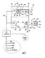
- FIG. 2is a schematic diagram of a cabinet system according to another exemplary embodiment of the invention.
- FIG. 3is a perspective view of a portion of a cabinet system according to an exemplary embodiment of the invention.
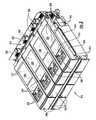
- FIG. 4is an exploded view of a drawer unit according to an exemplary embodiment of the invention.
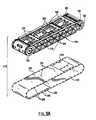
- FIG. 5Ais an exploded view of an insert of the drawer unit of FIG. 4 .
- FIG. 5Bis an exploded view of an alternate embodiment of an insert.
- FIG. 6is a perspective view of a portion of the drawer unit of FIG. 5 .
- FIG. 7is a perspective view of a portion of the cabinet system of FIG. 3 .
- FIG. 8is a schematic view of a portion of a cabinet system according to an exemplary embodiment of the invention.
- FIG. 9is a schematic view of a portion of a cabinet system according to another exemplary embodiment of the invention.
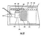
- FIG. 10is a schematic view of a portion of a cabinet system according to yet another exemplary embodiment of the invention.
- FIG. 11is a schematic view of a portion of a cabinet system according to still another exemplary embodiment of the invention.
- FIG. 12is a block diagram of an item management system.
- FIG. 13is a schematic illustration of a belt tension adjustment arrangement and a sensor assembly.
- FIG. 14is a schematic view of the compartments of a drawer unit in reference to a belt cover.
- Access to medical itemsmay be controlled by a storage cabinet system (e.g., medication cabinetry) designed to inhibit misuse, mistaken use, and theft of such items.
- the cabinet systemmay be used by doctors, nurses, technicians, pharmacists, and others to store and controllably distribute the items.
- a cabinet systemprovides selective access to the items, which are stored in one or more drawer units of the cabinet system.
- the cabinet systemis sensitive to unauthorized attempts to access the contents of the one or more drawer units, and stores data representative of such attempts, whether or not the attempts are successful.
- a cabinet system 110(e.g., dispensing station) includes a cabinet housing 112 (e.g., frame), a controller 114 , and one or more drawer units 116 (e.g., secure drawers with lids).
- the drawer units 116 of the cabinet system 110are arranged in one or more vertically-stacked rows 122 , each row 122 including one or more drawer units 116 .
- the drawer units 116 of the rows 122may be uniform in size (see, e.g., assembly 310 of drawer units 312 as shown in FIG. 3 ), or may include a variety of different sizes and relative capacities.
- One or more of the drawer units 116are configured to be releasably locked at least partially within the cabinet housing 112 by a locking mechanism (see, e.g., locking mechanism 222 as shown in FIG. 2 ). Locking of the drawer unit 116 within the cabinet housing 112 may inhibit unauthorized access to contents of the drawer unit 116 , and/or unauthorized removal of the entire drawer unit 116 . However, when the locking mechanism is released, the drawer unit 116 may be slid relative to the cabinet housing 112 , such as pulled partially or fully out of the cabinet housing 112 .
- a locking mechanismsee, e.g., locking mechanism 222 as shown in FIG. 2 .
- each drawer unit 116includes a storage compartment 118 (e.g., container) and a cover 120 coupled thereto.
- the storage compartment 118is designed to securely store one or more items therein, such as medical supplies, and the cover 120 is designed to move to an open configuration and a closed configuration. While in a closed configuration, the cover 120 is designed to limit access to the items of the storage compartment 118 . However, when the cover 120 is in the open configuration and the drawer unit 116 has been sufficiently slid from the cabinet housing 112 , contents of the storage compartment 118 may be accessible for removal from the drawer unit 116 .
- the controller 114is shown to include a computer terminal (e.g., laptop computer).
- the controller 114is in communication (e.g., wireless communication 124 or over a wired network) with at least one of the cabinet housing 112 and/or one of the drawer units 116 .
- the controller 114is configured to control operation of the locking mechanism, so as to control the release of the locking mechanism and correspondingly release the drawer unit 116 with respect to the cabinet housing 112 .
- the controller 114is further configured to control movement of the cover 120 , such as to move the cover 120 from the closed configuration to the open configuration, and/or visa versa.
- At least one of the drawer units 116includes a tamper detection system.
- the drawer unit 116is sensitive to additional movements of the cover 120 . For example, if a would-be thief attempts to manually force movement of the cover 120 to gain unauthorized access to additional compartments, a component(s) (e.g., sensor) of the drawer unit 116 provides notice of the attempt—regardless of whether the attempt was successful or not. In some embodiments, the component generates a signal that triggers an alarm.
- the signalis stored in memory coupled to the drawer unit 116 , and/or communicated to the controller 114 to be analyzed and possibly further communicated.
- the memorymay be coupled to the cabinet housing 112 or to the controller 114 .
- a cabinet system 210includes a cabinet housing 212 , a controller 214 , an upper drawer unit 216 , and a lower drawer unit 218 .
- each drawer unit 216 , 218includes at least a first storage compartment 224 and a second storage compartment 226 .
- Each storage compartment 224 , 226is configured to store (e.g., hold, contain) one or more items.
- a locking mechanism 222is configured to releasably lock each drawer unit 216 , 218 at least partially within the cabinet housing 212 —for example, substantially within the cabinet housing 212 , but with an end (e.g., face, handle, extensions) of each drawer unit 216 , 218 extending from the cabinet housing 212 .
- a cover 230 of the upper drawer unit 216is in a closed configuration, blocking access to contents of the storage compartments 224 , 226 thereof.
- a cover 232 of the lower drawer unit 218is in an open configuration relative to the first storage compartment 224 thereof, where the cover 232 is clear of an opening 234 (e.g., open end, top) of the first storage compartment 224 .
- items stored in the first storage compartment 224 of the lower drawer unit 218may be accessed (e.g., removed, added, replaced, used).
- items stored in the second storage compartment 226 of the lower drawer unit 218are inaccessible as shown in FIG. 2 , because the cover 232 is in a closed configuration relative to the second storage compartment 226 blocking access thereto.
- the cabinet housing 212includes a vertical arrangement of enclosures 250 (e.g., bays, openings, etc.). Each enclosure 250 includes a rear portion 244 and a front portion 242 . The front portion 242 of each enclosure 250 is configured to receive at least one drawer unit 216 , 218 inserted through an opening and slid within the cabinet housing 212 toward the rear portion 244 . Proximate to the rear portion 244 of each enclosure 250 , the cabinet housing 212 includes a connector 248 (e.g., port, interface, link, coupling) for receiving a complementary connector 246 coupled each drawer unit 216 , 218 .
- a connector 248e.g., port, interface, link, coupling
- the connectors 246 , 248allows for power and/or data communication between the controller 214 and the drawer units 216 , 218 , where the controller 214 is linked to the enclosures 250 of the cabinet housing 212 by wire 260 .
- the connectors 246 , 248may be disconnected from each other when each drawer unit 216 , 218 is slid away from the rear portion 244 of the enclosure 250 , and may be reconnected when the respective drawer unit 216 , 218 is then slid back to the rear portion 244 of the enclosure 250 , reconnecting the connectors 246 , 248 .
- At least one of the connectors 246 , 248includes one or more spring-loaded pins (see, e.g., pins 330 as shown in FIG. 3 ) and the other of the connectors 246 , 248 includes one or more complementary ports configured to receive the pins.
- the pinsmay be pulled from the ports as the drawer units 216 , 218 are slid away from the rear portion 244 of the cabinet housing 212 , and then reconnected to the ports when the drawer units 216 , 218 are slid back.
- the controller 214 and each drawer unit 216 , 218remain in continuous communication (e.g., wired or wireless communication), even when the drawer units 216 , 218 are slid partially out of each enclosure 250 .
- the controller 214may include a broad range of control devices, such as a general purpose processor, application-specific integrated circuitry, a digital control interface mounted directly to the cabinet housing, a handheld remote control, a network of computers hard-wired to the cabinet system 210 , or any other collection of circuitry components configured to conduct calculations or to facilitate the activities described herein.
- the controller 214may be in wired or wireless communication, fiber optic communication, communication via mechanical linkage, or otherwise coupled to at least one of the cabinet housing 212 and/or one of the drawer units 216 , 218 of the cabinet system 210 .
- the controller 214 of FIG. 2may also be linked to a network 254 , such as an arrangement of hospital computers coupled to the internet or databases containing medical item information, medical personnel authorization information, or patient-related care information.
- the controller 214is configured to operate the locking mechanism 222 for each drawer unit 216 , 218 via an actuator 252 , such as an electric solenoid coupled to the locking mechanism 222 .
- the locking mechanism 222includes at least one of a latch, a pin, a hook, a sliding bar, an interfering member, or another type of locking mechanisms, such as other remotely-controllable locking mechanisms that are commercially available. While the locking mechanism 222 in FIG.
- each drawer unit 216 , 218is shown to selectively lock an underside 262 of each drawer unit 216 , 218 to the rear portion 244 of each enclosure 250 , it is contemplated that in other embodiments a locking mechanism may be configured to selectively lock any portion of each drawer unit 216 , 218 to any other portion of the cabinet system 210 .
- the controller 214is further configured to operate the covers 230 , 232 of the drawer units 216 , 218 , such as to instruct one or more of the covers 230 , 232 to move to an open configuration relative to one or more of the respective compartments 224 , 226 .
- movement of the covers 230 , 232may occur while each drawer unit 216 , 218 is in one of the enclosures 250 , such that the items of the drawer units 216 , 218 may be then accessible when the drawer units 216 , 218 are sufficiently slid out of the cabinet housing 212 .
- the covers 230 , 232are configured to move forward and backward (e.g., bi-directionally) relative to the compartments 224 , 226 .
- the controller 214is still further configured to operate a lock 256 coupled to each cover 230 , 232 .
- the lock 256may be used to fix the respective cover 230 , 232 in a particular configuration, orientation, or position when the corresponding drawer unit 216 , 218 is slid away from the rear portion 244 of the cabinet housing 212 .
- the lock 256may include, but is not limited to a solenoid configured to engage locking holes in the covers 230 , 232 (see, e.g., track 338 with perforations 346 as shown in FIG.
- a spring-biased latchconfigured to engage each cover 230 , 232 when the respective drawer unit 216 , 218 is removed from the cabinet housing 212 , and/or a high-ratio gear reduction (e.g., high-reduction gear box) of an electric motor 258 or other actuator used for controllably moving the covers 230 , 232 , where with the electric motor 258 stopped, the gear reduction is difficult to manually overcome.
- the covers 230 , 232may be braked or locked by a motor brake or by reversing the polarity of the motor.
- each drawer unit 216 , 218is coupled to an electronic memory 236 and a power source 238 for the electronic memory 236 .
- memory 236 and power source 238are physically supported by their respective drawer units to move with the drawer units when they are moved.
- the electronic memory 236may store data in a variety of states, such as volatile, non-volatile, random-access memory, read-only memory, solid states, and the like.
- the electronic memory 236is configured to store (e.g., record, retain, hold) data associated with movement of the covers 230 , 232 .
- the electronic memory 236stores when the covers 230 , 232 are directed to move by the controller 214 , and/or when the covers 230 , 232 are manually forced to move, such during an attempted theft of items stored in the cabinet system 210 . In some embodiments, the electronic memory 236 stores such data regardless of whether the covers 230 , 232 are fully moved to an open or closed configuration.
- the electronic memory 236is coupled to a clock and stores the time, date, and duration of movements of the covers 230 , 232 and/or relative configurations, positions, and orientations of the covers 230 , 232 (e.g., data such as: ‘compartment 226 of drawer unit 218 was open from 18:00:31 to 18:17:09 hours on Month, Day, Year).
- the electronic memory 236is configured to only store data when the covers 230 , 232 have been manually forced to move, such as without authorization from the controller 214 .
- Datamay include data representative of one or more signals generated by encoders (e.g.
- the power source 238 for the electronic memory 236includes a battery, a power cell, a capacitor selectively charged by the controller 214 , and/or other power sources, which may be coupled to each drawer unit 216 , 218 .
- Memory of eventsmay be recorded on the electronic memory 236 and retained for download, even after the power source 238 has expired or terminated.
- the electronic memory 236may distinguish between authorized and unauthorized manual movements of the covers 230 , 232 .
- the electronic memorymay record when an authorized user is implementing a manual key override, such as during a power outage.
- an unauthorized movement of the covers 230 , 232may be detected by comparing the relative position of one of the covers 230 , 232 before and after a drawer unit 216 , 218 has been accessed, not requiring use of the electronic memory 236 and power source 238 .
- datamay be transferred from the electronic memory 236 to the controller 214 .
- data stored on the electronic memory 236may be downloaded by the controller (e.g., processor) and analyzed.
- the datamay include a broad spectrum of information, including by way of non-limiting example, a time and date of access or movement, contents of a drawer unit, a form of access (e.g., authorized or unauthorized, manual or automatic, etc.), accessing individual, form of authorization (e.g., prescription code, etc.), duration of access, and other such data. Analysis of the data may be designed to determine whether an attempt had been made to access to the items within the cabinet system 210 without authorization.
- electronic memory 236is attached to each of the drawer units 216 , 218 in FIG. 2
- electronic memorymay coupled to a controller, a cabinet housing, or elsewhere in a cabinet system, and analysis of data collected regarding movement of a cover for a drawer unit may be performed in real time, substantially as the cover is moved.
- At least one of the drawer units 216 , 218further includes a sensor 270 (e.g., photosensor, accelerometer, reed switch) coupled to the respective cover 230 , 232 .
- the sensor 270is configured and arranged so as to directly or indirectly detect movement of the respective cover 230 , 232 , and to communicate the movement to the electronic memory 236 and/or to the controller 214 .
- the sensor 270includes a potentiometer coupled to a pivot or wheel associated with movement of the cover (see, e.g., roller 332 as shown in FIG. 4 ). The potentiometer generates an electric signal responsive to movement of the cover 232 relative to the compartments 224 , 226 .
- the cover 230 , 232includes the electric motor 258 or other actuator configured to move the cover 230 , 232 in response to instructions from the controller 214 .
- Manual movement of the electric motor 258e.g., reverse operation thereof
- the electronic memory 236which records data representative of the electric signal, and in turn of the manual movement of the cover 230 , 232 .
- each drawer unit 216 , 218includes an alarm 264 .
- Another alarm 266is coupled to the controller 214 .
- an electric signal generated in response to movement of one of the covers 230 , 232is also directed to at least one of the alarms 264 , 266 , which are configured to provide notice (e.g., alert, warn, broadcast) of unauthorized attempts to access items stored in the cabinet system 210 .
- the alarm 266may be triggered subsequent to an unauthorized attempt, following analysis of data downloaded by the controller 214 from the electronic memory 236 .
- the alarms 264 , 266may be visual alarms, such as flashing lights, liquid crystal displays, light-emitting diode displays, warning messages, or other such visual signals.
- the alarms 264 , 266may be audio alarms, such as beeping, sirens, pre-recorded messages, or other such audio signals, or a combination of both visual and audio signals.
- the alarm 266may be a silent alarm, not intended to be noticed by the someone triggering the alarm 266 , such as an electronic-mail (e-mail) message automatically transmitted, which reports an incident to an email account of at least one pre-determined person (e.g., on-call doctor, hospital security, etc.).
- each drawer unit 312includes a cover 320 (e.g., sliding cover, indexing belt, hinged cover, removable cover, etc.) having an opening 322 therein.
- Each drawer unit 312further includes side walls 328 ( FIG. 4 ) that form compartments 334 interior to the drawer unit 312 .
- Restraining bars 340are biased to hold contents of the compartments 334 within the compartments 334 when the opening 322 of the cover 320 is aligned with each compartment 334 . However, the bars 340 may be manually lifted or pivoted as necessary to remove items from the compartments 334 . In still other embodiments, restraining bars are not included.
- a visual interfacesuch as a light-emitting diode (LED) display 348 , is coupled to a face 350 of at least one of the drawer units 312 .
- the LED display 348is configured to provide a visual signal to a user of the cabinet system.
- the visual signal of the LED display 348indicates that unauthorized tampering has occurred with the respective drawer unit 312 .
- the LED display 348provides other information, such as contents of the drawer unit 312 , supply status information, etc.
- a controllermay be in electrical or other communication with the drawer units 312 .
- the rear portion 314 of the cabinet housingmay also include an interlock (e.g., a switch, spring pin connection, etc.) that can break communication between the controller and the drawer units 312 when a substantial portion of each drawer unit 312 is slid from the rear portion 314 of the cabinet housing (e.g., substantial enough that an unauthorized person could grip and pull the drawer unit 312 and/or cover 320 in order to force access to the compartments 334 thereof).
- spring-loaded connection pins 330separate connectivity between the drawer unit 312 from the rear portion 314 , cutting communication between the drawer unit 312 and the controller, upon sliding of the drawer unit 312 from the rear portion 314 of the cabinet housing.
- the cover 320forms a closure with respect to the compartments 334 of the drawer unit 312 .
- the cover 320may be moved by an electric motor 352 (see FIG. 6 ), repositioning the opening 322 of the cover 320 to allow controlled access to one or more of the compartments 334 and/or to form a closure with respect to other compartments 334 .
- sliding of the drawer unit 312 from the rear portion 314 of the cabinet housingstops the flow of electricity to the electric motor 352 (see FIG. 6 ) used to move the cover 320 interlocking the cover 320 .
- the rear portion 314 of the cabinet housingincludes a circuitry board (e.g., firmware, programmable read-only memory (PROM)) and a releasable latch 354 ( FIG. 7 ), both coupled to the controller.
- the latch 354is configured to lock the drawer unit 312 to the rear portion 314 of the cabinet housing.
- An actuator 342e.g., solenoid, motorized pulley
- the drawer unit 312may slide relative to the cabinet housing along a slide rail 344 that extends from the rear portion 314 of the cabinet housing.
- the drawer unit 312includes a top frame 316 (e.g. cover), an insert 318 , and a shell 324 .
- the insert 318fits within the shell 324
- the top frame 316with flanges 326 extending therefrom, fits over the insert 318 and attaches to the shell 324 .
- the top frame 316can be securely fastened to the shell 324 by means of a thumb screw or other fasteners, to prevent removal of the insert 318 from the shell 324 .
- the insert 318includes the cover 320 , a side wall 328 , and rollers 332 .
- the cover 320may slide relative to the side wall 328 and compartments 334 via the rollers 332 .
- the insert 318includes intermediary flanges 372 extending from the side wall 328 (or from the shell 324 ) to contact receiving portions 374 of the shell 324 in order to separate the cover 320 from the shell 324 during movement of the cover 320 (i.e., providing space for the cover 320 to move).
- the insert 318includes the cover 320 and a body 336 .
- the body 336includes divider walls 356 and side walls 328 , which together form compartments 334 .
- some of the divider walls 356may be fixed while others may be removable, providing adjustable compartmentalization.
- the insert 318can optionally have two, three, or four compartments 334 , depending upon the use of the removable divider walls 356 . Items of varying sizes may be stored in differently sized compartments 334 .
- the cover 320may include two openings 322 , one configured to match a larger compartment and the other sized for a smaller compartment.
- the fixed divider walls 356may be injection molded with the body 336 , glued, welded, or otherwise fixed to the body 336 .
- a body of an insertmay be both longer and/or deeper (or shorter and/or narrower) than the body 336 of FIG. 5 .
- a body of an insertmay include up to six compartments, with ten such inserts in a drawer assembly (cf. assembly 310 as shown in FIG. 3 ).
- FIG. 5Bis similar to FIG. 5A , however, it includes more compartments.
- insertsmay include sprockets which drive both sides of a cover.
- the cover 320may be an indexing belt made of a continuous material, such as about 0.005 inch thick stainless steel sheet.
- Other contemplated embodimentsinclude belts of thicker clear mylar, polycarbonate sheet, rubber, or other materials.
- the cover 320is preferably made to be flexible, such that the cover 320 may bend about a portion of the insert 318 , such as a roller 332 . Bending of the cover 320 allows for a more-compact drawer unit design, because unused portions of the cover 320 may be folded about the body 336 .
- Other contemplated embodimentsinclude flexible covers, such as straps, strips, bands, and the like, which may not slide fully around the body 336 .
- some embodimentsinclude spools for winding the flexible covers for storage and control thereof.
- the cover 320is designed with a series of small holes 358 that are in coded sequences, readable by a sensor.
- the coded sequencesvary at different positions on the cover 320 , such that detection of a portion of the coded sequence by the sensor provides positional information to the controller of the cover 320 orientation relative to the body 336 .
- Still other embodimentscount rotations of one of the rollers 332 to determine the position of the cover 320 relative to a starting position thereof.
- holesmay be noncircular, such as diamond-shaped, teardrop shaped, or otherwise shaped. Including a corner (e.g., crack initiation location, vertex) to the shape of the holes may improve tamper evidence by facilitating a controlled tearing of the cover if unauthorized, forced entry is attempted.
- rollers 332are positioned on the longitudinal ends of the insert 318 , where at least one of the rollers 332 is in the form of a sprocket 360 (with teeth).
- the cover 320includes perforated tracks 338 .
- the teeth of the sprocket 360fit the perforations 346 , such that the cover 320 is moved relative to the body 336 via controlled rotation of the sprocket 360 .
- rollers 332have a high-friction surface, such as sandpaper grit or a gripping rubber, for providing force to move the cover 320 , without teeth.
- the rollers 332may be injection molded from Celcon or Delrin materials, cast or molded metals, and/or composites.
- FIG. 6further illustrates the side walls 328 , a removable divider wall 356 , rollers 332 (one being a sprocket 360 ), the electric motor 352 , and a gear reduction 362 .
- the electric motor 352e.g., direct current motor
- the electric motor 352is coupled to the gear reduction 362 , which in turn is coupled to the sprocket 360 , coupled to the cover 320 .
- the electric motor 352is selectively powered by the controller via a power/data bus coupled to the insert 318 , and selectively connected to a power source when the drawer unit 312 is locked within the cabinet housing.
- the inserts 318 of FIGS. 5A and 5Bmay additionally include a data storage device coupled to the power/data bus.
- the data storage deviceis coupled to the electric motor 352 (illustrated in FIG. 6 ).
- Manual sliding of the cover 320forces the electric motor 352 to operate in reverse, generating an electric signal that is transmitted on the power/data bus.
- Data representative of the electric signalis stored on the data storage device 373 .
- the data storage device 373is a mechanical detection device, such as a spring-loaded interlock. Manual sliding of the cover 320 triggers the interlock, which locks the cover 320 and may additionally trigger an alarm.
- the shell 324may be locked to the rear portion 314 of the cabinet housing by a latch 354 .
- the latch 354extends beneath the shell 324 and connects to the shell 324 via a strike 364 (e.g., reinforced hole, catch) coupled to the shell 324 .
- the latch 354is coupled with the actuator 342 , which is coupled by the controller to selectively release the shell 324 .
- a security deflection tab 366e.g., “fishability bracket”
- FIG. 4may serve to block attempts to manipulate the latch 354 from an above position, such as by drilling a hole in the top of the cabinet housing and reaching down through the hole with a rod to release the latch 354 .
- a second tab 368extends from the shell 324 to block attempts to manipulate the latch 354 from the front of the cabinet housing.
- a manual release plate 370allows for release of the drawer units 312 by key, code, etc., during a power outage (e.g., manual key override).
- a drawer 412includes at least one compartment 418 and an actuator (e.g., electric motor, solenoid, electromagnet pair, etc.) in the form of an electric motor 420 , which is coupled to a sprocket 422 .
- a cover 424is coupled to the drawer 412 and is configured to selectively block access to the compartment 418 .
- the cover 424is a belt that surrounds at least a portion of the drawer 412 .
- An opening 426 in the covermay be aligned with the compartment 418 in the drawer 412 .
- Alignment of the opening 426 of the cover 424 with the compartment 418allows for access to items stored in the compartment 418 and while simultaneously preventing access to other compartments in drawer 412 . Misalignment of the opening 426 of the cover 424 with the compartment 418 allows the cover 424 to block access to the items.
- the sprocket 422is configured to engage a track 428 on the cover 424 to move the cover 424 (and the opening 426 therein) relative to the drawer 412 (and compartment 418 therein).
- the electric motor 420 of the drawer 412includes electric leads 430 (e.g., wires, conductive extensions, prongs, etc.) in electrical communication with the working components (e.g., rotor/stator portions) of the motor 420 .
- the leads 430are configured to engage couplings 432 associated with a housing 416 .
- the leads 430 of the motor 420are in electrical communication with a power source connected through the housing 416 .
- the leads 430are decoupled from the power source, breaking electrical connectivity to the motor 420 . Accordingly, the motor 420 does not rotate the sprocket 422 , and the cover 424 is not moved by the motor 420 when the drawer 412 is slid from an enclosure 414 .
- cabinet system 410includes a locking mechanism for locking the cover 424 when the drawer 412 is slid from the housing 416 , which includes a switch 434 (e.g., relay) extending between the leads 430 of the motor 420 .
- the switch 434is open when the drawer 412 is electrically coupled to the power source by way of the couplings 432 of the housing 416 .
- the switch 434is automatically closed, shorting the leads 430 of the electric motor 420 .
- the internal components of the motor 420e.g., rotator/stator, drive shaft, gear reduction, transmission, etc.
- the internal components of the motor 420serve as an interlock, resisting manual movement of the cover 424 by an unauthorized user.
- One type of effective gear reduction for providing lockingis a 90° worm-gear drive. (Not specifically shown.)
- Shorting the leads 430also may serve to prevent an unauthorized user from attaching a supplemental power source to the leads 430 , to power the motor 420 (e.g., hotwire the motor 420 ).
- the switch 434 and electric motor 420as coupled to the cover 424 by way of the sprocket 422 , serve as a locking mechanism (e.g., brake) for the cover 424 when the drawer 412 is removed from the cabinet housing 416 .
- the motor 420will generate electricity (e.g. a voltage and/or current) when manually operated in reverse, the occurrence of which may be recorded in an electric memory as evidence of tampering.
- drawer 512also has a compartment 514 and an electric motor 516 coupled to a sprocket 518 .
- the cover 528is movable by the electric motor 516 via rotation of the sprocket 518 which engages a track 530 on the cover 528 . Movement of the cover 528 provides selective access to items stored in the compartment 514 of the drawer 512 by way of an opening 532 in the cover.
- a locking mechanism in the form of a pin 534may be used to lock the cover 528 relative to the drawer 512 (and the compartment 514 therein).
- the pin 534may be biased by a spring 536 and may interlock the cover 528 when the drawer 512 is slid from the housing 520 . Sliding the drawer 512 from the housing 520 may release the pin 534 from being held in place by the housing 520 , releasing tension on the spring 536 , which slides the pin 534 into a corresponding slot 538 in the cover 528 .
- the housing 520reengages the pin 534 , removing the pin 534 from the slot 538 and unlocking the cover 528 .
- the pin 534may be used in conjunction with a switch selectively coupling the leads 526 (see, e.g., switch 434 as shown in FIG. 8 ).
- the pin 534may also be positioned within an electromagnet 540 (e.g., acting as solenoid), and is biased by the spring 536 in opposition to electromagnetic forces on the pin 534 selectively provided by the electromagnet 540 .
- an electromagnet 540e.g., acting as solenoid
- the pin 534is pulled against the spring 536 , compressing the spring 536 .
- the spring 536is released, pushing the pin 534 forward to engage and lock the cover 528 in the slot 538 (e.g., hole) therein.
- a manual override keye.g., physical key, push button code, etc.
- a clamp coupled to the pin 534may be used to selectively grip the cover, in place of engagement with the slot 538 .
- drawer 614includes several compartments 616 for storage of medical items.
- a cover 618 having an opening 620 thereinis coupled to the drawer 614 , and moveable relative to the compartments 616 of the drawer 614 via a sprocket 622 coupled to a motor 624 , the sprocket 622 engaging a track 626 on the cover 618 .
- a locking mechanism in the form of a motor brake 628(e.g. function brake or jaw brake) is coupled to the motor 624 .
- the motor brake 628is configured to lock a shaft 630 of the motor 624 when electrical power is cut to the motor brake 628 .
- a power sourceis coupled to the drawer 614 by way of couplings 632 of the housing 612 that may be selectively connected to leads 634 of the motor 624 and to the motor brake 628 of the drawer 614 . When the drawer 614 is pulled from the cabinet housing 612 , electricity to the drawer 614 is cut and the cover 618 is locked relative to the compartments 616 of the drawer 614 .
- the cover 618is released and may be moved (by way of the motor 624 and sprocket 622 ) relative to the compartments 616 of the drawer 614 to block or allow access to items stored therein.
- FIG. 11another version of the drawer, drawer 714 , is shown.
- an electric motor 716is powered via an electric coupling 728 with the housing 712 driving a worm gear 718 by way of intermediate gearing 720 is configured to control movement of a cover 722 that includes an opening 724 that is adjustable to selectively block access to contents stored in a compartment 726 of the drawer 714 .
- the drawer 714is electrically coupled to a power source, and the motor 716 controls rotation of the worm gear 718 to move the cover 722 .
- electrical connectivity between the drawer 714 and the power sourceis severed.
- the worm gear 718 and motor 716serve as an interlock, preventing manual movement of the cover 722 by an unauthorized user attempting to gain access to items stored in a compartment 726 of the drawer 714 that is intended by a controller of the cabinet system 710 to be closed.
- FIGS. 8-11Although electrical connectivity in FIGS. 8-11 is shown as a coupling of leads of the electric motors connected to leads extending from the cabinet housing, in other embodiments the power source or a portion of the power source may be coupled to a drawer even when the drawer is pulled from the cabinet housing. Movement of the drawer, or relative position of the drawer may trigger actuation of a combination of the locking mechanisms of FIGS. 8-11 . Additionally, alternative locking mechanisms that are commercially available, may be used in combination with the or in place of the locking mechanisms shown in FIGS. 8-11 , to control access to items securely stored in the drawers.
- a cabinet system 810(e.g., item management system, controlled-access medication dispensing system) includes cabinet hardware 816 including a first stationary cabinet 890 , a second stationary cabinet 892 that is smaller than the first stationary cabinet 890 , and a portable cabinet 880 (e.g., including wheels or casters 882 ).
- the first and second stationary cabinets 890 , 892are linked together via a communication wire 874
- the first stationary cabinet 890is linked with the portable cabinet 880 via wireless communication 876 (e.g., RF).
- the first and second stationary cabinets 890 , 892include structure for coupling the cabinets 890 , 892 together, either side-by-side or one on top of the other.
- the cabinet system 810further includes a computerized controller 814 (e.g., electronic control system), which includes a user interface 822 (e.g., terminal) and a computer 824 having a processor, memory, and a logic module.
- the computerized controller 814may further or otherwise include a server 830 and additional computers and terminals 872 .
- the computerized controller 814is connected to an interface 870 on the first stationary cabinet 890 , and is also connected to the second stationary cabinet 892 and the portable cabinet 880 by way of the first stationary cabinet 890 (e.g., daisy-chain arrangement). In other embodiments, the controller 814 is directly connected to the second stationary cabinet 892 and the portable cabinet 880 .
- Each of the cabinets 890 , 892 , 880include one or more drawer units 850 that are slidable within housings 852 (e.g., bays, enclosures) of the cabinets 890 , 892 , 880 .
- the system 810may also include a locking connector 854 (e.g., a latch) that selectively locks the drawer units 850 within the housing 852 .
- the interfaces 870connect the controller 814 via a bus 820 to sensors 844 , the locking connector 854 , and other components within the housing 852 .
- the drawer units 850are locked within the housings 852 of the cabinets 890 , 892 , 880 until released by the computerized controller 814 .
- Each of the drawer units 850include one or more compartments formed therein (shown as large and small boxes in each drawer unit 850 ), within which items may be securely stored.
- Covers 842are coupled to the drawer units 850 . Sensory data from the sensors 844 allows the controller 814 to estimate a position of the covers 842 .
- the coversare designed to selectively block access to the compartments when the drawer units 850 have been slid from the housing 852 .
- the computerized controller 814may instruct an actuator 840 coupled to one of the drawer units 850 to move the respective cover 842 relative to the drawer unit 850 .
- the compartmentmay be accessed by an authorized operator of the system 810 when the drawer unit 850 has been slid from the housing 852 .
- FIGS. 5A , 5 B, 6 , and 8 - 11A number of embodiments of the drawer units have been described above in reference to the figures (e.g. FIGS. 5A , 5 B, 6 , and 8 - 11 ).
- various forms of belt tensioningmay be used.
- One exampleis to provide fixed rollers/sprockets 332 on each end of the belt with an adjustable idler roller or slide to tension the belt.
- Another exampleis to provide a tensioning assembly which is configured to permit both removal and tensioning of the belt relative to a drawer unit. This is accomplished by supporting the shaft of at least one of the belt rollers/sprockets 332 with bearings which are adjustable relative to the frame of the drawer unit.
- This form of adjustmentincludes having the bearings slidably mounted on slides which permit movement of the roller along a path generally parallel to the length of the belt. The slides are moved with adjustment screws or bolts and can be held in place with set screws.
- FIG. 13schematically illustrates a form of the second example of the tension adjustment discussed.
- each side of the roller shaft 1302is supported by a slide assembly 1304 .
- a bolt 482is engaged with a threaded portion of the sliding portion of assembly 1304 .
- the head of bolt 482rests against an adjustment stop 1308 so that when bolt 482 is turned into the threaded portion, the belt 320 (also referred to as cover) is tightened.
- the belt 320can be tightened and adjusted so that the belt 320 is not biased to tend to move off of the rollers 332 .
- FIG. 13also shows a sensor assembly which includes an optical sensor 492 attached to a back wall a cabinet housing proximate to the back side of a drawer unit.
- the assemblyalso includes light source 494 (e.g. LED) which directs light from the interior of belt through openings 358 (see FIGS. 5A and 5B ) of belt 320 toward sensor 492 .
- the sensor assemblyprovides belt orientation information to controller 214 (see FIG. 2 ), so that the controller 214 may operate the motor 352 (see FIG. 6 ) (or other actuator) in relation to a current and/or desired orientation of the belt 320 .
- openings 358are either uniformly spaced to provide uniform light interruptions which generate interrupt signals to the controller which are interpreted by the controller to determine the location of the belt openings relative to the compartments. This is done typically with the use of an initial position which has a unique light interruption, and then counting of interrupt signals from the initial position.
- the openings 358may be patterned such that sensor 492 generates a signal representative of the pattern of openings 358 detected when light is transmitted through the belts. These signals are transmitted to the controller 214 which interprets the signals to determine the location of the belt openings relative to the compartments based on the coded patterns that vary at different positions on the belt 320 . Detection of a particular coded sequence by the sensor 492 provides positional information.
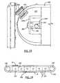
- FIG. 14a side schematic view of a drawer unit having a 3 compartments arranged end to end from a first end to a second end.
- One of the compartmentsis divided in half to form 2 half-size compartments.
- the belt rollers 332 supported at each end of the belt 320are also schematically shown in combination with belt 320 .
- Belt 320has 2 openings which are schematically marked as A and B. Opening B is sized to correspond to the size of a half-size compartment.
- a belt actuatorwhich includes a motor such as motor 352 (see FIG. 6 ) moves the belt 320 to align one of the openings A or B with the opening of a compartment 334 which includes a desired item such as a particular medication. By properly aligning an opening in the belt with the opening of one compartment, the remainder of the belt serves to restrict access to the other compartments of the drawer unit when the user slides the drawer unit from the associated cabinet.
- the belt 320is moved to align an opening A, B in the belt 320 with the opening in a compartment when the drawer unit is located within the cabinet. Accordingly, when a cabinet user requests a particular item, the actuator operates to move the belt 320 to provide access to the compartment having the requested item. Initiating and completing this operation must be done in the shortest period of time within which the system is capable of operating. The speed of operation is limited by the belt, drawer unit, actuator, and other drawer structure parameters. Accordingly, for a given set of parameters operation of the belt must be optimized.
- the belt actuatoris configured so that the belt 320 may be moved in both directions.
- arrows Cillustrate belt motion in either the clockwise or counter-clockwise directions.
- the distance of travel or movementis defined as either the time or physical distance the belt must travel to move either opening A or opening B over the opening of the compartment 334 which contains a selected item.
- the distance of travelwill typically be different depending upon the direction of travel (e.g. clockwise or counter-clockwise).
- the distance of travel in the clockwise direction required to move opening B over compartment C 6is much less than the distance of travel in the counter-clockwise direction.
- controller 214is programmed to keep track of belt 320 opening A, B positions relative to compartments C 1 -C 6 , and to select the direction of travel to minimize the distance of travel.
- Controller 214may also be programmed to keep track of the frequency at which items in the compartments C 1 -C 6 are accessed and position the belt 320 when the drawer unit is not in use to increase the likelihood that belt travel will be minimized.
- controller 214would position belt 320 so that opening B was located generally in the vicinity of compartments C 1 and C 3 when the drawer is returned and locked in the cabinet and not in use. This would result in opening B being positioned over approximately over compartment C 2 depending upon whether or not the speed of belt movement available from the actuator is designed for a particular application to be the same in both directions.
- cabinet systemas shown in the various exemplary embodiments are illustrative only. Although only a few embodiments have been described in detail in this disclosure, many modifications are possible (e.g., variations in sizes, dimensions, structures, shapes and proportions of the various elements, values of parameters, mounting arrangements, use of materials, colors, orientations, etc.) without materially departing from the novel teachings and advantages of the subject matter described herein.
- elements shown as integrally formedmay be constructed of multiple parts or elements, the position of elements may be reversed or otherwise varied, and the nature or number of discrete elements or positions may be altered or varied.
- the order or sequence of any process, logical algorithm, or method stepsmay be varied or re-sequenced according to alternative embodiments.
- Other substitutions, modifications, changes and omissionsmay also be made in the design, operating conditions and arrangement of the various exemplary embodiments without departing from the scope of the present invention.
Landscapes
- Health & Medical Sciences (AREA)
- General Physics & Mathematics (AREA)
- Physics & Mathematics (AREA)
- Engineering & Computer Science (AREA)
- Public Health (AREA)
- General Health & Medical Sciences (AREA)
- Life Sciences & Earth Sciences (AREA)
- Medical Informatics (AREA)
- Animal Behavior & Ethology (AREA)
- Veterinary Medicine (AREA)
- Surgery (AREA)
- Chemical & Material Sciences (AREA)
- Bioinformatics & Cheminformatics (AREA)
- Medicinal Chemistry (AREA)
- Epidemiology (AREA)
- Primary Health Care (AREA)
- Molecular Biology (AREA)
- Heart & Thoracic Surgery (AREA)
- Biomedical Technology (AREA)
- Nuclear Medicine, Radiotherapy & Molecular Imaging (AREA)
- Drawers Of Furniture (AREA)
Abstract
Description
Claims (23)
Priority Applications (8)
| Application Number | Priority Date | Filing Date | Title |
|---|---|---|---|
| US13/087,070US8744621B2 (en) | 2009-01-09 | 2011-04-14 | Medical cabinet access belt optimization system |
| PCT/US2012/030922WO2012141893A2 (en) | 2011-04-14 | 2012-03-28 | Medical cabinet access belt optimization system |
| CA2828628ACA2828628C (en) | 2011-04-14 | 2012-03-28 | Medical cabinet access belt optimization system |
| US14/256,740US9345644B2 (en) | 2009-01-09 | 2014-04-18 | Medical cabinet access belt optimization system |
| US15/072,008US9511001B2 (en) | 2009-01-09 | 2016-03-16 | Medical cabinet access belt optimization system |
| US15/295,706US9925123B2 (en) | 2009-01-09 | 2016-10-17 | Medical cabinet access belt optimization system |
| US15/891,937US10123944B2 (en) | 2009-01-09 | 2018-02-08 | Medical cabinet access belt optimization system |
| US16/157,936US10342740B2 (en) | 2009-01-09 | 2018-10-11 | Medical cabinet access belt optimization system |
Applications Claiming Priority (4)
| Application Number | Priority Date | Filing Date | Title |
|---|---|---|---|
| US12/351,679US8103379B2 (en) | 2009-01-09 | 2009-01-09 | Medication cabinetry |
| US13/032,753US8588966B2 (en) | 2009-01-09 | 2011-02-23 | Cabinet system |
| US13/040,931US9121197B2 (en) | 2009-01-09 | 2011-03-04 | Cabinet system with improved drawer security |
| US13/087,070US8744621B2 (en) | 2009-01-09 | 2011-04-14 | Medical cabinet access belt optimization system |
Related Parent Applications (1)
| Application Number | Title | Priority Date | Filing Date |
|---|---|---|---|
| US13/040,931Continuation-In-PartUS9121197B2 (en) | 2009-01-09 | 2011-03-04 | Cabinet system with improved drawer security |
Related Child Applications (1)
| Application Number | Title | Priority Date | Filing Date |
|---|---|---|---|
| US14/256,740ContinuationUS9345644B2 (en) | 2009-01-09 | 2014-04-18 | Medical cabinet access belt optimization system |
Publications (2)
| Publication Number | Publication Date |
|---|---|
| US20110196538A1 US20110196538A1 (en) | 2011-08-11 |
| US8744621B2true US8744621B2 (en) | 2014-06-03 |
Family
ID=47009910
Family Applications (6)
| Application Number | Title | Priority Date | Filing Date |
|---|---|---|---|
| US13/087,070Active2029-09-05US8744621B2 (en) | 2009-01-09 | 2011-04-14 | Medical cabinet access belt optimization system |
| US14/256,740ActiveUS9345644B2 (en) | 2009-01-09 | 2014-04-18 | Medical cabinet access belt optimization system |
| US15/072,008ActiveUS9511001B2 (en) | 2009-01-09 | 2016-03-16 | Medical cabinet access belt optimization system |
| US15/295,706ActiveUS9925123B2 (en) | 2009-01-09 | 2016-10-17 | Medical cabinet access belt optimization system |
| US15/891,937ActiveUS10123944B2 (en) | 2009-01-09 | 2018-02-08 | Medical cabinet access belt optimization system |
| US16/157,936ActiveUS10342740B2 (en) | 2009-01-09 | 2018-10-11 | Medical cabinet access belt optimization system |
Family Applications After (5)
| Application Number | Title | Priority Date | Filing Date |
|---|---|---|---|
| US14/256,740ActiveUS9345644B2 (en) | 2009-01-09 | 2014-04-18 | Medical cabinet access belt optimization system |
| US15/072,008ActiveUS9511001B2 (en) | 2009-01-09 | 2016-03-16 | Medical cabinet access belt optimization system |
| US15/295,706ActiveUS9925123B2 (en) | 2009-01-09 | 2016-10-17 | Medical cabinet access belt optimization system |
| US15/891,937ActiveUS10123944B2 (en) | 2009-01-09 | 2018-02-08 | Medical cabinet access belt optimization system |
| US16/157,936ActiveUS10342740B2 (en) | 2009-01-09 | 2018-10-11 | Medical cabinet access belt optimization system |
Country Status (3)
| Country | Link |
|---|---|
| US (6) | US8744621B2 (en) |
| CA (1) | CA2828628C (en) |
| WO (1) | WO2012141893A2 (en) |
Cited By (23)
| Publication number | Priority date | Publication date | Assignee | Title |
|---|---|---|---|---|
| US20140172161A1 (en)* | 2012-10-03 | 2014-06-19 | James Marcus Norris | Controlling dispensing of items |
| US20140222196A1 (en)* | 2009-01-09 | 2014-08-07 | Automed Technologies, Inc. | Medical cabinet access belt optimization system |
| US20150005934A1 (en)* | 2013-06-28 | 2015-01-01 | Carefusion 303, Inc. | Secure medication transport |
| US20150041355A1 (en)* | 2011-11-08 | 2015-02-12 | Isish Healthcare System, S.L. | Tube for Storing Unit Doses of a Drug, Method and Device for Filling Same and Dispensing Cabinet Using Same |
| US9117016B2 (en) | 2012-07-23 | 2015-08-25 | Omnicare, Inc. | Universal label and verification systems and methods for filling customer orders of medical items |
| US9208635B2 (en)* | 2012-09-28 | 2015-12-08 | Innovative Product Achievements, Llc | Item dispensing apparatus |
| US9245406B2 (en) | 2007-05-04 | 2016-01-26 | Innovative Product Achievements, Llc | Apparatus for inserting a cart, such as a cart with one or more fixed wheels, into an enclosure |
| US9478093B2 (en) | 2012-02-15 | 2016-10-25 | Innovative Product Achievements, Llc | Item dispensing apparatus |
| US9770106B2 (en)* | 2009-01-09 | 2017-09-26 | Arxium, Inc. | Cabinet system with improved drawer security |
| US9809240B2 (en) | 2015-02-02 | 2017-11-07 | Innovative Product Achievements, Llc | Item dispensing apparatus |
| US9891658B2 (en) | 2010-01-27 | 2018-02-13 | Arxium, Inc. | Medical supply cabinet with lighting features |
| US9888774B2 (en)* | 2009-01-09 | 2018-02-13 | Arxium, Inc. | Medication cabinetry |
| US20180235843A1 (en)* | 2007-10-30 | 2018-08-23 | Carefusion 303, Inc. | Managing medications at the bedside |
| US20190060176A1 (en)* | 2017-08-31 | 2019-02-28 | Omnicell, Inc. | Unit dose dispensing mechanisms |
| US10262490B2 (en) | 2015-02-27 | 2019-04-16 | Omnicell, Inc. | Unit dose dispensing systems and methods |
| USD862941S1 (en)* | 2016-12-01 | 2019-10-15 | Gühring KG | Tool cabinet |
| US20200032555A1 (en)* | 2011-01-24 | 2020-01-30 | Carefusion 303, Inc. | Self-aligning modular latch |
| US10751239B2 (en) | 2015-11-13 | 2020-08-25 | Humanscale Corporation | Medical technology station and method of use |
| US11078997B2 (en) | 2015-07-20 | 2021-08-03 | National Machine Group | Motor driven electromechanical actuator |
| US11246800B2 (en)* | 2012-10-05 | 2022-02-15 | Alixa Rx, Llc | Locking canister for dispensing medications |
| US20230072341A1 (en)* | 2021-09-03 | 2023-03-09 | Inventec (Pudong) Technology Corporation | Hard disk supporting structure |
| US11908307B2 (en) | 2018-06-07 | 2024-02-20 | William J. Hoofe, IV | Security system |
| US12008888B1 (en) | 2021-08-09 | 2024-06-11 | William J. Hoofe, IV | Security system |
Families Citing this family (24)
| Publication number | Priority date | Publication date | Assignee | Title |
|---|---|---|---|---|
| US20100300130A1 (en)* | 2006-03-29 | 2010-12-02 | S&S X-Ray Products, Inc. | Medical Storage Case with Remote Unlocking Refrigerator with thermal Spoilage Protection |
| US8588966B2 (en) | 2009-01-09 | 2013-11-19 | Automed Technologies, Inc. | Cabinet system |
| US9078520B2 (en)* | 2011-11-08 | 2015-07-14 | S&S X-Ray, Products Inc | Locking bin drawer with slide-out trays for medications cabinet |
| US8700211B2 (en) | 2011-11-08 | 2014-04-15 | S & S X-Ray Products, Inc | Slide bar locking drawer for medications cabinet |
| DE102011086423B4 (en)* | 2011-11-15 | 2014-05-08 | Trumpf Medizin Systeme Gmbh + Co. Kg | Carrier system for a medical supply unit |
| US9195804B2 (en)* | 2012-12-06 | 2015-11-24 | S & S X-Ray Products | Daisy chain array of medications cabinets |
| US9387153B1 (en)* | 2013-06-19 | 2016-07-12 | Robert G. Mazur | Metered dispensing system |
| AU2014292968B2 (en) | 2013-07-26 | 2019-06-20 | Helmer Scientific, Llc | Medical products storage device including access control |
| US20160259904A1 (en)* | 2015-03-03 | 2016-09-08 | Abide Technologies, Llc | System and method for providing dispensing security for controlled substances within a care facility |
| US10490016B2 (en)* | 2015-05-13 | 2019-11-26 | Carefusion Germany 326 Gmbh | Device for packaging medication portions |
| US10346590B2 (en)* | 2015-08-21 | 2019-07-09 | Scriptpro Llc | Prescription storage and retrieval system |
| US20170156985A1 (en)* | 2015-12-04 | 2017-06-08 | Hayley Sebrina Guldan | Personal electronic medication safe |
| US10406074B1 (en) | 2016-01-21 | 2019-09-10 | Robert Gerhard Mazur | Medication dispensing tray adapter and system |
| CN105996492A (en)* | 2016-07-27 | 2016-10-12 | 国网山东省电力公司惠民县供电公司 | Power supply system for medical instruments |
| EP4531014A3 (en) | 2017-10-17 | 2025-06-25 | Helmer Scientific, LLC | Undercounter refrigerator with access control |
| CN108245258A (en)* | 2018-01-10 | 2018-07-06 | 徐莉 | A kind of intelligence surgery edge of a knife restores care device |
| CN108516272B (en)* | 2018-04-23 | 2020-06-12 | 合肥哈工众志自动化科技有限公司 | a shelf |
| CN110002161B (en)* | 2019-04-15 | 2021-05-11 | 南通大学附属医院 | A hospital intelligent drug classification management device |
| CN110200419B (en)* | 2019-07-02 | 2024-05-10 | 欧艳 | Novel infusion bottle storage cabinet and storing and taking method thereof |
| US11615875B2 (en)* | 2020-03-30 | 2023-03-28 | Omnicell, Inc. | Sensor driven secure dispensing unit |
| US12045773B2 (en)* | 2020-05-29 | 2024-07-23 | Ethicon, Inc. | Inventory system and methods of using the same |
| US20220076815A1 (en)* | 2020-09-10 | 2022-03-10 | Mark KENNER | Apparatus, method, and system for medical instrument management and distribution |
| CN114348512B (en)* | 2022-01-07 | 2024-01-23 | 重庆名医在线信息技术有限公司 | Intelligent medicine distribution system |
| US20240078894A1 (en)* | 2022-09-06 | 2024-03-07 | FireAvert, LLC | Smoke alarm tamper protection device |
Citations (122)
| Publication number | Priority date | Publication date | Assignee | Title |
|---|---|---|---|---|
| US3682113A (en)* | 1971-01-25 | 1972-08-08 | Meilink Steel Safe Co | Deal drawer |
| US4057145A (en) | 1976-03-19 | 1977-11-08 | Wray Betty B | Compliance dispenser for oral medication |
| US4267942A (en) | 1979-06-20 | 1981-05-19 | John B. Wick, Jr. | Pharmaceutical dispensing cabinet |
| US4785969A (en) | 1986-11-10 | 1988-11-22 | Pyxis Corporation | Medication dispensing system |
| US4865404A (en) | 1988-07-18 | 1989-09-12 | Harpers | Interlock for multi-drawer cabinet |
| US4927051A (en) | 1987-10-26 | 1990-05-22 | Unidynamics Corporation | Multiple-product merchandising machine |
| US4941570A (en) | 1989-04-19 | 1990-07-17 | Easco Hand Tools, Inc. | Wrench socket dispenser |
| US5014875A (en)* | 1989-03-01 | 1991-05-14 | Pyxis Corporation | Medication dispenser station |
| US5046455A (en) | 1990-12-17 | 1991-09-10 | Christiansen Steven A | Automatic animal feeder |
| US5087107A (en) | 1989-01-19 | 1992-02-11 | M.I.B. Elettronica S.R.L. | Device and process for protecting and handling bank notes and valuables |
| US5222789A (en) | 1990-11-29 | 1993-06-29 | Koichi Yoshikawa | Drawer system |
| US5255971A (en) | 1990-08-31 | 1993-10-26 | Zaca Inc. | Medicine cabinet |
| US5259668A (en) | 1991-03-01 | 1993-11-09 | Artromick International Inc. | Cart for medication |
| US5263596A (en) | 1991-12-02 | 1993-11-23 | Williams David R | Medication dispenser station sub-assembly |
| US5282678A (en) | 1991-03-01 | 1994-02-01 | Artromick International, Inc. | Cart for medication |
| US5322365A (en) | 1992-04-10 | 1994-06-21 | Artromick International, Inc. | Vertically adjustable extension drawers |
| US5346297A (en) | 1993-01-04 | 1994-09-13 | Colson Jr Angus R | Auxiliary storage and dispensing unit |
| US5377864A (en) | 1989-05-25 | 1995-01-03 | Baxter International Inc. | Drug dispensing apparatus |
| US5404384A (en) | 1993-01-25 | 1995-04-04 | Medselect Systems, Inc. | Inventory monitoring apparatus employing counter for adding and subtracting objects being monitored |
| US5405048A (en) | 1993-06-22 | 1995-04-11 | Kvm Technologies, Inc. | Vacuum operated medicine dispenser |
| US5445295A (en) | 1992-01-17 | 1995-08-29 | Brown; Graham | Automated vending machine system for recorded goods |
| US5460294A (en) | 1994-05-12 | 1995-10-24 | Pyxis Corporation | Single dose pharmaceutical dispenser subassembly |
| US5467266A (en)* | 1991-09-03 | 1995-11-14 | Lutron Electronics Co., Inc. | Motor-operated window cover |
| US5533079A (en) | 1993-01-25 | 1996-07-02 | Medselect Systems, Inc. | Inventory monitoring apparatus |
| US5713485A (en) | 1995-10-18 | 1998-02-03 | Adds, Inc. | Drug dispensing system |
| US5724764A (en) | 1995-10-10 | 1998-03-10 | Alsup; Charles Kent | Storage box |
| US5745366A (en) | 1994-07-14 | 1998-04-28 | Omnicell Technologies, Inc. | Pharmaceutical dispensing device and methods |
| US5790409A (en) | 1993-01-25 | 1998-08-04 | Medselect Systems, Inc. | Inventory monitoring and dispensing system for medical items |
| US5797515A (en) | 1995-10-18 | 1998-08-25 | Adds, Inc. | Method for controlling a drug dispensing system |
| US5805456A (en) | 1994-07-14 | 1998-09-08 | Omnicell Technologies, Inc. | Device and method for providing access to items to be dispensed |
| US5839257A (en) | 1996-04-22 | 1998-11-24 | Automed Technologies Incorporated | Drug packaging machine |
| US5848593A (en) | 1994-12-16 | 1998-12-15 | Diebold, Incorporated | System for dispensing a kit of associated medical items |
| US5905653A (en) | 1994-07-14 | 1999-05-18 | Omnicell Technologies, Inc. | Methods and devices for dispensing pharmaceutical and medical supply items |
| US5912818A (en) | 1993-01-25 | 1999-06-15 | Diebold, Incorporated | System for tracking and dispensing medical items |
| US5927540A (en) | 1997-08-20 | 1999-07-27 | Omnicell Technologies, Inc. | Controlled dispensing system and method |
| US5961036A (en) | 1996-07-12 | 1999-10-05 | Diebold, Incorporated | Apparatus and method for accepting return of unused medical items |
| US6011999A (en) | 1997-12-05 | 2000-01-04 | Omnicell Technologies, Inc. | Apparatus for controlled dispensing of pharmaceutical and medical supplies |
| US6019249A (en) | 1997-04-30 | 2000-02-01 | Diebold, Incorporated | Apparatus for dispensing medical items |
| US6109774A (en) | 1995-08-01 | 2000-08-29 | Pyxis Corporation | Drawer operating system |
| US6116461A (en) | 1998-05-29 | 2000-09-12 | Pyxis Corporation | Method and apparatus for the dispensing of drugs |
| US6151536A (en) | 1998-09-28 | 2000-11-21 | Omnicell.Com | Dispensing system and methods |
| US6170929B1 (en) | 1998-12-02 | 2001-01-09 | Ronald H. Wilson | Automated medication-dispensing cart |
| US6170230B1 (en) | 1998-12-04 | 2001-01-09 | Automed Technologies, Inc. | Medication collecting system |
| US6175779B1 (en) | 1998-09-29 | 2001-01-16 | J. Todd Barrett | Computerized unit dose medication dispensing cart |
| US6256967B1 (en) | 1998-08-27 | 2001-07-10 | Automed Technologies, Inc. | Integrated automated drug dispenser method and apparatus |
| US20010019065A1 (en) | 1997-12-05 | 2001-09-06 | William Jeffrey P. | Pill dispensing system |
| JP2001275766A (en) | 2000-03-31 | 2001-10-09 | Kyoei Ind Co Ltd | Cabinet with device latching safely |
| US20010044731A1 (en) | 2000-05-18 | 2001-11-22 | Coffman Damon J. | Distributed remote asset and medication management drug delivery system |
| US6401991B1 (en) | 2001-02-15 | 2002-06-11 | Kathleen H. Eannone | Computer timed-locked medication container with individual compartments |
| US6427865B1 (en) | 1998-04-15 | 2002-08-06 | Kenneth Stillwell | Automatic pill dispenser |
| US6502718B2 (en)* | 2001-03-19 | 2003-01-07 | Innovative Product Achievements, Inc. | Garment dispensing and receiving apparatus having a removable cartridge body and a flexible dispensing door |
| US6564121B1 (en) | 1999-09-22 | 2003-05-13 | Telepharmacy Solutions, Inc. | Systems and methods for drug dispensing |
| US6594549B2 (en) | 2001-04-04 | 2003-07-15 | Bruce Siegel | Web-enabled medication dispenser |
| US6609047B1 (en) | 1993-07-21 | 2003-08-19 | Omnicell Technologies, Inc. | Methods and apparatus for dispensing items |
| US6650964B2 (en) | 2002-04-16 | 2003-11-18 | Mckesson Automation Inc. | Medication dispensing apparatus override check and communication system |
| US6658322B1 (en) | 2000-05-05 | 2003-12-02 | Medselect Inc. | System and method for tracking medical items and supplies |
| US6662081B1 (en) | 2000-06-08 | 2003-12-09 | Medport Llc | Medication regimen container and system |
| US20040026442A1 (en) | 2002-08-09 | 2004-02-12 | Mckesson Automation Sys Inc | Vacuum pill dispensing cassette and counting machine |
| US20040104652A1 (en) | 2002-08-07 | 2004-06-03 | Holmes William K. | Apparatus for securing drawer contents |
| US6746091B2 (en) | 2001-12-05 | 2004-06-08 | Artromick International, Inc. | Cart locking device |
| US6760643B2 (en) | 1994-10-11 | 2004-07-06 | Omnicell, Inc. | Methods and apparatus for dispensing items |
| US20040134043A1 (en) | 2002-12-25 | 2004-07-15 | Sanyo Electric Co., Ltd. | Medicine supply apparatus |
| US6775591B1 (en) | 2003-01-24 | 2004-08-10 | S&S X-Ray Products, Inc. | Portable medication dispensing unit |
| US20040158350A1 (en) | 2001-05-15 | 2004-08-12 | Jens Ostergaard | Medicine dispenser |
| US6776306B1 (en) | 1997-04-30 | 2004-08-17 | Medselect Inc. | Apparatus for dispensing medical items |
| US6785589B2 (en) | 2001-11-30 | 2004-08-31 | Mckesson Automation, Inc. | Dispensing cabinet with unit dose dispensing drawer |
| US6788997B1 (en) | 1998-06-01 | 2004-09-07 | Medselect, Inc. | Medical cabinet with adjustable drawers |
| US6847861B2 (en) | 2001-11-30 | 2005-01-25 | Mckesson Automation, Inc. | Carousel product for use in integrated restocking and dispensing system |
| US6895304B2 (en) | 2001-12-07 | 2005-05-17 | Mckesson Automation, Inc. | Method of operating a dispensing cabinet |
| US6902083B1 (en) | 1997-04-30 | 2005-06-07 | Automed Technologies, Inc. | Method for dispensing medical items |
| US20050145644A1 (en) | 2002-02-20 | 2005-07-07 | Sanyo Electric Co., Ltd. | Chemical feeding device |
| US6975922B2 (en) | 2003-05-08 | 2005-12-13 | Omnicell, Inc. | Secured dispensing cabinet and methods |
| US6997377B2 (en) | 2002-12-31 | 2006-02-14 | Diebold Self-Service Systems Division Of Diebold, Incorporated | ATM cassette with self-locking media directing guide |
| US7006893B2 (en) | 1999-09-22 | 2006-02-28 | Telepharmacy Solutions, Inc. | Systems for dispensing medical products |
| US20060079994A1 (en) | 2004-10-08 | 2006-04-13 | Chu Woei C | Unit-dose medication dispensing cart and method of operating the same |
| US7044569B1 (en) | 1996-11-04 | 2006-05-16 | Artromick International, Inc. | Modular drawer system |
| US7048142B1 (en) | 1997-04-30 | 2006-05-23 | Automed Technologies, Inc. | Apparatus for dispensing medical items |
| US7052097B2 (en) | 2002-12-06 | 2006-05-30 | Mckesson Automation, Inc. | High capacity drawer with mechanical indicator for a dispensing device |
| US20060125356A1 (en) | 2004-12-03 | 2006-06-15 | Mckesson Automation Inc. | Mobile point of care system and associated method and computer program product |
| US20060151517A1 (en) | 2002-08-21 | 2006-07-13 | Reijo Varis | Device for dispensing tablet-or capsule-shaped medicaments in desired doses |
| US7077286B2 (en) | 2002-08-09 | 2006-07-18 | Mckesson Automation Systems Inc. | Drug dispensing cabinet having a drawer interlink, counterbalance and locking system |
| US20060197419A1 (en) | 2005-03-03 | 2006-09-07 | Sorensen Robert J | Overhead storage device |
| US20060277269A1 (en) | 2005-06-02 | 2006-12-07 | Automed Technologies, Inc. | Apparatus and methods for dispensing pre-filled containers with precisely-applied patient-specific information |
| US7152441B2 (en) | 2004-03-11 | 2006-12-26 | Artromick International, Inc. | Cart locking device |
| US20070023193A1 (en) | 2003-09-17 | 2007-02-01 | King Roy D | Inventory control system |
| US20070078562A1 (en) | 2005-10-03 | 2007-04-05 | Sabal Medical, Inc. | Mobile medication storage and dispensing apparatus |
| JP2007126270A (en) | 2005-11-07 | 2007-05-24 | Sumita System:Kk | Picking device |
| US7228200B2 (en) | 2004-04-22 | 2007-06-05 | Parata Systems, Llc | Apparatus, system and methods for dispensing products |
| US7258241B2 (en) | 2005-03-31 | 2007-08-21 | Amerisourcebergen Drug Corporation | Method and apparatus for facilitating bar-code scanning of rack contents using rack column mounted display |
| US7258249B1 (en) | 2000-05-05 | 2007-08-21 | Automed Technologies, Inc. | Medical item storage cabinet and method |
| US20070208598A1 (en) | 1994-12-16 | 2007-09-06 | Mcgrady R M | Method of dispensing and tracking the giving of medical items to patients |
| US7293673B2 (en) | 2004-09-08 | 2007-11-13 | Supplypro, Inc. | Drawer item dispenser |
| US20070262147A1 (en) | 2006-05-10 | 2007-11-15 | Mckesson Automation Inc. | System, method and corresponding apparatus for storing, retrieving and delivering unit dose blisters |
| US20070283733A1 (en) | 2006-06-12 | 2007-12-13 | Ratkus Jeffery R | Electronic locking system |
| US20080065264A1 (en) | 2004-09-03 | 2008-03-13 | Tosho Inc. | Medical Resource Storage and Management Apparatus and Medical Supply Management System |
| US20080129171A1 (en) | 2002-02-06 | 2008-06-05 | Lori Greiner | Jewelry organizer |
| US7395945B2 (en) | 2004-09-24 | 2008-07-08 | Nexiant | Controlled dispensing system with modular carousel |
| US20080190953A1 (en) | 2003-09-19 | 2008-08-14 | Vesta Medical, Llc | Combination Disposal and Dispensing Apparatus and Method |
| US7427022B2 (en) | 2004-04-01 | 2008-09-23 | Matsushita Electric Industrial Co., Ltd. | Ticket management system, terminal device, ticket management server, register device, value conversion method, computer program, and recording medium |
| US7434704B2 (en) | 2002-08-05 | 2008-10-14 | Yuyama Mfg. Co., Ltd. | Medicine feeder |
| US7463947B1 (en) | 2000-05-05 | 2008-12-09 | Automed Technologies, Inc. | Medical item storage cabinet and method |
| US7467093B1 (en) | 1994-12-16 | 2008-12-16 | Automed Technologies, Inc | Method of tracking and despensing medical items to patients through self service delivery system |
| US7464832B2 (en) | 2003-12-31 | 2008-12-16 | Lg N-Sys Inc. | Media cassette with internal lock |
| US20090015116A1 (en) | 2003-02-24 | 2009-01-15 | Rubbermaid Commercial Products, Llc | Medical cart, medication module, height adjustment mechanism, and method of medication transport |
| US7502666B2 (en) | 2004-05-14 | 2009-03-10 | Mts Medication Technologies, Inc. | Systems and methods for storing and dispensing medication |
| US20090108016A1 (en) | 2007-10-30 | 2009-04-30 | Cardinal Health 303, Inc. | Secure medication transport and administration system |
| US20090114672A1 (en) | 2007-02-09 | 2009-05-07 | Cerner Innovation, Inc. | Medication dispensing apparatus for dispensing single items from multiple-compartment bins |
| US20090138122A1 (en) | 2007-11-26 | 2009-05-28 | Wagner David J | Pharmacy medication verification system |
| US7596427B1 (en) | 2000-05-05 | 2009-09-29 | Automed Technologies, Inc. | Medical item storage cabinet and method |
| US7630791B2 (en)* | 2005-12-09 | 2009-12-08 | CareFusion 303 Inc. | System and method for storing items and tracking item usage |
| US7685026B1 (en) | 2000-05-05 | 2010-03-23 | Automed Technologies, Inc. | Method of tracking and dispensing medical items |
| US7689316B1 (en) | 2000-05-05 | 2010-03-30 | Automed Technologies, Inc. | Medical item storage cabinet and method |
| US20100079240A1 (en) | 2004-07-29 | 2010-04-01 | Omnicell, Inc. | Rfid cabinet |
| US7719420B2 (en) | 2008-02-14 | 2010-05-18 | Mckesson Automation Inc. | Lock status notification and next case medication method, apparatus and corresponding medication storage device |
| US20100176699A1 (en) | 2009-01-09 | 2010-07-15 | Amerisourcebergen Corporation | Medication cabinetry |
| US20100228392A1 (en) | 2009-03-03 | 2010-09-09 | McKesson Automation Inc., | Medication Storage And Dispensing Unit Having A Vial Dispenser |
| US7823993B2 (en) | 2007-04-03 | 2010-11-02 | Carefusion 303, Inc. | Piezo actuated slide latching mechanism |
| US20110015782A1 (en) | 2003-12-05 | 2011-01-20 | Automed Technologies, Inc. | Pharmacy dispensing system and method |
| US8068932B2 (en)* | 2007-08-14 | 2011-11-29 | Roche Diagnostics Operations, Inc. | Access-controlled storage system |
| US8180484B2 (en)* | 2004-04-22 | 2012-05-15 | Parata Systems, Llc | Apparatus, system and methods for dispensing products |
| US8197017B2 (en) | 2009-07-20 | 2012-06-12 | Carefusion 303, Inc. | Rotating multi-latch release mechanism |
| US8234008B2 (en) | 2008-02-29 | 2012-07-31 | Carefusion 303, Inc. | Lidded drawer for single line item dispensing |
Family Cites Families (31)
| Publication number | Priority date | Publication date | Assignee | Title |
|---|---|---|---|---|
| GB8519701D0 (en) | 1985-08-06 | 1985-09-11 | Videomat Automation Ltd | Dispensing apparatus |
| US4763810A (en) | 1986-12-19 | 1988-08-16 | Christiansen Lee T | Medication dispenser |
| AT393956B (en) | 1989-10-20 | 1992-01-10 | Loidl Rudolf | DEVICE FOR STORING AND TIMELY TAKING DRUGS |
| US5392951A (en) | 1993-05-20 | 1995-02-28 | Lionville Systems, Inc. | Drawer operating system |
| US5431299A (en) | 1994-01-26 | 1995-07-11 | Andrew E. Brewer | Medication dispensing and storing system with dispensing modules |
| AU3638495A (en)* | 1994-09-28 | 1996-04-19 | Kvm Technologies, Inc. | Secure medication storage and retrieval system |
| US8423180B1 (en) | 1994-12-16 | 2013-04-16 | Automed Technologies, Inc. | System for tracking and dispensing medical items from environmentally controlled storage area |
| CN2254674Y (en) | 1996-06-30 | 1997-05-28 | 姜祝萍 | Household health medicine cabinet |
| US6348864B1 (en) | 2000-05-06 | 2002-02-19 | Magnex Corporation | Organizer management system using R.F. identification |
| US6532399B2 (en)* | 2001-06-05 | 2003-03-11 | Baxter International Inc. | Dispensing method using indirect coupling |
| US20030201697A1 (en) | 2002-04-30 | 2003-10-30 | Richardson William R. | Storage device for health care facility |
| US20040050750A1 (en)* | 2002-09-18 | 2004-03-18 | Hannan Robin E. | Medication cart drawer liner and method for using same to reduce nosocomial infections |
| JP2005143401A (en) | 2003-11-17 | 2005-06-09 | Satomi Matoba | Toilet for small animal |
| JP2005287609A (en) | 2004-03-31 | 2005-10-20 | Katsutoshi Ando | Multifunctional storage case for notebook computer |
| US7533797B2 (en)* | 2004-05-10 | 2009-05-19 | Apg Cash Drawer | Short depth cash drawer with a moveable base |
| JP4626370B2 (en) | 2005-04-11 | 2011-02-09 | ブラザー工業株式会社 | Image forming apparatus |
| JP4923734B2 (en) | 2005-05-31 | 2012-04-25 | 株式会社湯山製作所 | Drug packaging device |
| US8276739B2 (en)* | 2007-01-25 | 2012-10-02 | Bastian Material Handling, Llc | Three-dimensional automated pick module |
| US7782198B2 (en) | 2007-12-03 | 2010-08-24 | International Business Machines Corporation | Apparatus and method for detecting tampering of a printer compartment |
| GB2461070A (en) | 2008-06-19 | 2009-12-23 | Shafir Production Systems Ltd | Cabinet for handling distributable items comprising drawer access and control system and lockable bins |
| KR100963597B1 (en) | 2008-07-18 | 2010-06-15 | 강연균 | Closed Circulation Reagent Center |
| US8165929B2 (en)* | 2008-08-04 | 2012-04-24 | Chudy Group, LLC | Adaptive pharmaceutical product management methods and system |
| US8744621B2 (en)* | 2009-01-09 | 2014-06-03 | Automed Technologies, Inc. | Medical cabinet access belt optimization system |
| US8588966B2 (en) | 2009-01-09 | 2013-11-19 | Automed Technologies, Inc. | Cabinet system |
| US9121197B2 (en) | 2009-01-09 | 2015-09-01 | Automed Technologies, Inc. | Cabinet system with improved drawer security |
| US8262174B2 (en) | 2009-06-05 | 2012-09-11 | Carefusion 303, Inc. | Multi-latch release mechanism |
| US8746908B2 (en) | 2010-01-27 | 2014-06-10 | Automed Technologies, Inc. | Medical supply cabinet with lighting features |
| US8335588B2 (en) | 2010-06-30 | 2012-12-18 | Carefusion 303, Inc. | Multi-lidded dispensing cartridge system |
| US9243427B2 (en) | 2011-01-24 | 2016-01-26 | Carefusion 303, Inc. | Self-aligning modular latch |
| US9122783B2 (en)* | 2012-07-23 | 2015-09-01 | Omnicare, Inc. | Automated label and verification systems and methods for filling customer orders of medical items |
| CN106226768B (en) | 2016-08-09 | 2018-08-21 | 北京空间飞行器总体设计部 | Ultrahigh resolution agility SAR satellites slide beam bunching mode System Parameter Design method |
- 2011
- 2011-04-14USUS13/087,070patent/US8744621B2/enactiveActive
- 2012
- 2012-03-28CACA2828628Apatent/CA2828628C/enactiveActive
- 2012-03-28WOPCT/US2012/030922patent/WO2012141893A2/enactiveApplication Filing
- 2014
- 2014-04-18USUS14/256,740patent/US9345644B2/enactiveActive
- 2016
- 2016-03-16USUS15/072,008patent/US9511001B2/enactiveActive
- 2016-10-17USUS15/295,706patent/US9925123B2/enactiveActive
- 2018
- 2018-02-08USUS15/891,937patent/US10123944B2/enactiveActive
- 2018-10-11USUS16/157,936patent/US10342740B2/enactiveActive
Patent Citations (165)
| Publication number | Priority date | Publication date | Assignee | Title |
|---|---|---|---|---|
| US3682113A (en)* | 1971-01-25 | 1972-08-08 | Meilink Steel Safe Co | Deal drawer |
| US4057145A (en) | 1976-03-19 | 1977-11-08 | Wray Betty B | Compliance dispenser for oral medication |
| US4267942A (en) | 1979-06-20 | 1981-05-19 | John B. Wick, Jr. | Pharmaceutical dispensing cabinet |
| US4785969A (en) | 1986-11-10 | 1988-11-22 | Pyxis Corporation | Medication dispensing system |
| US4927051A (en) | 1987-10-26 | 1990-05-22 | Unidynamics Corporation | Multiple-product merchandising machine |
| US4865404A (en) | 1988-07-18 | 1989-09-12 | Harpers | Interlock for multi-drawer cabinet |
| US5087107A (en) | 1989-01-19 | 1992-02-11 | M.I.B. Elettronica S.R.L. | Device and process for protecting and handling bank notes and valuables |
| US5014875A (en)* | 1989-03-01 | 1991-05-14 | Pyxis Corporation | Medication dispenser station |
| US4941570A (en) | 1989-04-19 | 1990-07-17 | Easco Hand Tools, Inc. | Wrench socket dispenser |
| US5377864A (en) | 1989-05-25 | 1995-01-03 | Baxter International Inc. | Drug dispensing apparatus |
| US5255971B1 (en) | 1990-08-31 | 1996-12-17 | Zaca Inc | Medicine cabinet |
| US5255971A (en) | 1990-08-31 | 1993-10-26 | Zaca Inc. | Medicine cabinet |
| US5222789A (en) | 1990-11-29 | 1993-06-29 | Koichi Yoshikawa | Drawer system |
| US5046455A (en) | 1990-12-17 | 1991-09-10 | Christiansen Steven A | Automatic animal feeder |
| US5282678A (en) | 1991-03-01 | 1994-02-01 | Artromick International, Inc. | Cart for medication |
| US5743607A (en) | 1991-03-01 | 1998-04-28 | Artromick International, Inc. | Cart for medication |
| US5259668A (en) | 1991-03-01 | 1993-11-09 | Artromick International Inc. | Cart for medication |
| US5467266A (en)* | 1991-09-03 | 1995-11-14 | Lutron Electronics Co., Inc. | Motor-operated window cover |
| US5263596A (en) | 1991-12-02 | 1993-11-23 | Williams David R | Medication dispenser station sub-assembly |
| US5445295A (en) | 1992-01-17 | 1995-08-29 | Brown; Graham | Automated vending machine system for recorded goods |
| US5322365A (en) | 1992-04-10 | 1994-06-21 | Artromick International, Inc. | Vertically adjustable extension drawers |
| US5346297A (en) | 1993-01-04 | 1994-09-13 | Colson Jr Angus R | Auxiliary storage and dispensing unit |
| US5520450A (en) | 1993-01-04 | 1996-05-28 | Pyxis Corporation | Supply station with internal computer |
| US5533079A (en) | 1993-01-25 | 1996-07-02 | Medselect Systems, Inc. | Inventory monitoring apparatus |
| US6163737A (en) | 1993-01-25 | 2000-12-19 | Diebold, Incorporated | Medical item dispensing apparatus |
| US5404384A (en) | 1993-01-25 | 1995-04-04 | Medselect Systems, Inc. | Inventory monitoring apparatus employing counter for adding and subtracting objects being monitored |
| US5912818A (en) | 1993-01-25 | 1999-06-15 | Diebold, Incorporated | System for tracking and dispensing medical items |
| US5790409A (en) | 1993-01-25 | 1998-08-04 | Medselect Systems, Inc. | Inventory monitoring and dispensing system for medical items |
| US7689317B2 (en) | 1993-01-25 | 2010-03-30 | Automed Technologies, Inc. | Medical item inventory monitoring system with automatic electronic reordering |
| US7751932B1 (en) | 1993-01-25 | 2010-07-06 | Automed Technologies, Inc. | Method for tracking and dispensing medical items |
| US5405048A (en) | 1993-06-22 | 1995-04-11 | Kvm Technologies, Inc. | Vacuum operated medicine dispenser |
| US6609047B1 (en) | 1993-07-21 | 2003-08-19 | Omnicell Technologies, Inc. | Methods and apparatus for dispensing items |
| US5460294A (en) | 1994-05-12 | 1995-10-24 | Pyxis Corporation | Single dose pharmaceutical dispenser subassembly |
| US5745366A (en) | 1994-07-14 | 1998-04-28 | Omnicell Technologies, Inc. | Pharmaceutical dispensing device and methods |
| US5905653A (en) | 1994-07-14 | 1999-05-18 | Omnicell Technologies, Inc. | Methods and devices for dispensing pharmaceutical and medical supply items |
| US5805456A (en) | 1994-07-14 | 1998-09-08 | Omnicell Technologies, Inc. | Device and method for providing access to items to be dispensed |
| US6760643B2 (en) | 1994-10-11 | 2004-07-06 | Omnicell, Inc. | Methods and apparatus for dispensing items |
| US20070208598A1 (en) | 1994-12-16 | 2007-09-06 | Mcgrady R M | Method of dispensing and tracking the giving of medical items to patients |
| US7467093B1 (en) | 1994-12-16 | 2008-12-16 | Automed Technologies, Inc | Method of tracking and despensing medical items to patients through self service delivery system |
| US7349858B1 (en) | 1994-12-16 | 2008-03-25 | Automed Technologies, Inc. | Method of dispensing and tracking the giving of medical items to patients |
| US5848593A (en) | 1994-12-16 | 1998-12-15 | Diebold, Incorporated | System for dispensing a kit of associated medical items |
| US6109774A (en) | 1995-08-01 | 2000-08-29 | Pyxis Corporation | Drawer operating system |
| US5724764A (en) | 1995-10-10 | 1998-03-10 | Alsup; Charles Kent | Storage box |
| US7427002B2 (en) | 1995-10-18 | 2008-09-23 | Telepharmacy Solutions, Inc. | Method for controlling a drug dispensing system |
| US6471089B2 (en) | 1995-10-18 | 2002-10-29 | Telepharmacy Solutions, Inc. | Method for controlling a drug dispensing system |
| US6068156A (en) | 1995-10-18 | 2000-05-30 | Adds, Inc. | Method for controlling a drug dispensing system |
| US5797515A (en) | 1995-10-18 | 1998-08-25 | Adds, Inc. | Method for controlling a drug dispensing system |
| US7991507B2 (en) | 1995-10-18 | 2011-08-02 | Telepharmacy Solutions, Inc. | Method for controlling a drug dispensing system |
| US7151982B2 (en) | 1995-10-18 | 2006-12-19 | Telepharmacy Solutions, Inc. | Pharmaceutical dispensing system |
| US6814254B2 (en) | 1995-10-18 | 2004-11-09 | Telepharmacy Solutions, Incorporated | Method for controlling a drug dispensing system |
| US6814255B2 (en) | 1995-10-18 | 2004-11-09 | Telepharmacy Solutions, Inc. | Method for controlling a drug dispensing system |
| US6776304B2 (en) | 1995-10-18 | 2004-08-17 | Telepharmacy Solutions, Inc. | Method for controlling a drug dispensing system |
| US5713485A (en) | 1995-10-18 | 1998-02-03 | Adds, Inc. | Drug dispensing system |
| US6581798B2 (en) | 1995-10-18 | 2003-06-24 | Telepharmacy Solutions, Incorporated | Method for controlling a drug dispensing system |
| US20030088333A1 (en) | 1995-10-18 | 2003-05-08 | Telepharmacy Solutions, Incorporated | Method for controlling a drug dispensing system |
| US5839257A (en) | 1996-04-22 | 1998-11-24 | Automed Technologies Incorporated | Drug packaging machine |
| US6073834A (en) | 1996-07-12 | 2000-06-13 | Diebold, Incorporated | Apparatus and method for accepting return of unused medical items |
| US5961036A (en) | 1996-07-12 | 1999-10-05 | Diebold, Incorporated | Apparatus and method for accepting return of unused medical items |
| US7044569B1 (en) | 1996-11-04 | 2006-05-16 | Artromick International, Inc. | Modular drawer system |
| US6019249A (en) | 1997-04-30 | 2000-02-01 | Diebold, Incorporated | Apparatus for dispensing medical items |
| US6776306B1 (en) | 1997-04-30 | 2004-08-17 | Medselect Inc. | Apparatus for dispensing medical items |
| US6902083B1 (en) | 1997-04-30 | 2005-06-07 | Automed Technologies, Inc. | Method for dispensing medical items |
| US7048142B1 (en) | 1997-04-30 | 2006-05-23 | Automed Technologies, Inc. | Apparatus for dispensing medical items |
| US5927540A (en) | 1997-08-20 | 1999-07-27 | Omnicell Technologies, Inc. | Controlled dispensing system and method |
| US20010019065A1 (en) | 1997-12-05 | 2001-09-06 | William Jeffrey P. | Pill dispensing system |
| US6011999A (en) | 1997-12-05 | 2000-01-04 | Omnicell Technologies, Inc. | Apparatus for controlled dispensing of pharmaceutical and medical supplies |
| US6427865B1 (en) | 1998-04-15 | 2002-08-06 | Kenneth Stillwell | Automatic pill dispenser |
| US6338007B1 (en) | 1998-05-29 | 2002-01-08 | Pyxis Corporation | System and apparatus for the storage and dispensing of items |
| US6116461A (en) | 1998-05-29 | 2000-09-12 | Pyxis Corporation | Method and apparatus for the dispensing of drugs |
| US7630789B2 (en) | 1998-05-29 | 2009-12-08 | CareFusion 303 Inc. | System and apparatus for the dispensing of drugs |
| US7040504B2 (en) | 1998-05-29 | 2006-05-09 | Cardinal Health 301, Inc. | System and apparatus for the dispensing of drugs |
| US6788997B1 (en) | 1998-06-01 | 2004-09-07 | Medselect, Inc. | Medical cabinet with adjustable drawers |
| US6742671B2 (en) | 1998-08-27 | 2004-06-01 | Automed Technologies, Inc. | Integrated automated drug dispenser method and apparatus |
| US6256967B1 (en) | 1998-08-27 | 2001-07-10 | Automed Technologies, Inc. | Integrated automated drug dispenser method and apparatus |
| US6151536A (en) | 1998-09-28 | 2000-11-21 | Omnicell.Com | Dispensing system and methods |
| US6175779B1 (en) | 1998-09-29 | 2001-01-16 | J. Todd Barrett | Computerized unit dose medication dispensing cart |
| US6170929B1 (en) | 1998-12-02 | 2001-01-09 | Ronald H. Wilson | Automated medication-dispensing cart |
| JP2003509084A (en) | 1998-12-02 | 2003-03-11 | ネクストアールエックス・コーポレーション | Automatic drug distribution cart |
| US6625952B1 (en) | 1998-12-04 | 2003-09-30 | Automed Technologies, Inc. | Medication collecting system |
| US6170230B1 (en) | 1998-12-04 | 2001-01-09 | Automed Technologies, Inc. | Medication collecting system |
| US6735497B2 (en) | 1999-09-22 | 2004-05-11 | Telepharmacy Solutions, Inc. | Systems and methods for dispensing medical products |
| US6564121B1 (en) | 1999-09-22 | 2003-05-13 | Telepharmacy Solutions, Inc. | Systems and methods for drug dispensing |
| US7006893B2 (en) | 1999-09-22 | 2006-02-28 | Telepharmacy Solutions, Inc. | Systems for dispensing medical products |
| JP2001275766A (en) | 2000-03-31 | 2001-10-09 | Kyoei Ind Co Ltd | Cabinet with device latching safely |
| US7262698B1 (en) | 2000-05-05 | 2007-08-28 | Automed Technologies, Inc. | Medical item storage cabinet and method |
| US7685026B1 (en) | 2000-05-05 | 2010-03-23 | Automed Technologies, Inc. | Method of tracking and dispensing medical items |
| US7689316B1 (en) | 2000-05-05 | 2010-03-30 | Automed Technologies, Inc. | Medical item storage cabinet and method |
| US7263410B1 (en) | 2000-05-05 | 2007-08-28 | Automed Technologies, Inc. | Medical item storage cabinet and method |
| US6963791B1 (en) | 2000-05-05 | 2005-11-08 | Automed Technologies, Inc. | System and method for tracking medical items and supplies |
| US7258249B1 (en) | 2000-05-05 | 2007-08-21 | Automed Technologies, Inc. | Medical item storage cabinet and method |
| US6658322B1 (en) | 2000-05-05 | 2003-12-02 | Medselect Inc. | System and method for tracking medical items and supplies |
| US7515988B1 (en) | 2000-05-05 | 2009-04-07 | Automed Technologies, Inc. | Medical item storage cabinet and method |
| US7286900B1 (en) | 2000-05-05 | 2007-10-23 | Automed Technologies, Inc. | Medical item storage cabinet and method |
| US7596427B1 (en) | 2000-05-05 | 2009-09-29 | Automed Technologies, Inc. | Medical item storage cabinet and method |
| US7463947B1 (en) | 2000-05-05 | 2008-12-09 | Automed Technologies, Inc. | Medical item storage cabinet and method |
| US20010044731A1 (en) | 2000-05-18 | 2001-11-22 | Coffman Damon J. | Distributed remote asset and medication management drug delivery system |
| US6662081B1 (en) | 2000-06-08 | 2003-12-09 | Medport Llc | Medication regimen container and system |
| US6401991B1 (en) | 2001-02-15 | 2002-06-11 | Kathleen H. Eannone | Computer timed-locked medication container with individual compartments |
| US6502718B2 (en)* | 2001-03-19 | 2003-01-07 | Innovative Product Achievements, Inc. | Garment dispensing and receiving apparatus having a removable cartridge body and a flexible dispensing door |
| US6594549B2 (en) | 2001-04-04 | 2003-07-15 | Bruce Siegel | Web-enabled medication dispenser |
| US20040158350A1 (en) | 2001-05-15 | 2004-08-12 | Jens Ostergaard | Medicine dispenser |
| US7072737B2 (en) | 2001-11-30 | 2006-07-04 | Mckesson Automation, Inc. | Filling a restocking package using a carousel |
| US6785589B2 (en) | 2001-11-30 | 2004-08-31 | Mckesson Automation, Inc. | Dispensing cabinet with unit dose dispensing drawer |
| US6847861B2 (en) | 2001-11-30 | 2005-01-25 | Mckesson Automation, Inc. | Carousel product for use in integrated restocking and dispensing system |
| US7010389B2 (en) | 2001-11-30 | 2006-03-07 | Mckesson Automation, Inc. | Restocking system using a carousel |
| US6996455B2 (en) | 2001-11-30 | 2006-02-07 | Mckesson Automation Inc. | Dispensing cabinet with unit dose dispensing drawer |
| US6746091B2 (en) | 2001-12-05 | 2004-06-08 | Artromick International, Inc. | Cart locking device |
| US6985797B2 (en) | 2001-12-07 | 2006-01-10 | Mckesson Automation, Inc. | Method of operating a dispensing cabinet |
| US6895304B2 (en) | 2001-12-07 | 2005-05-17 | Mckesson Automation, Inc. | Method of operating a dispensing cabinet |
| US20080129171A1 (en) | 2002-02-06 | 2008-06-05 | Lori Greiner | Jewelry organizer |
| US20050145644A1 (en) | 2002-02-20 | 2005-07-07 | Sanyo Electric Co., Ltd. | Chemical feeding device |
| US7293672B2 (en) | 2002-02-20 | 2007-11-13 | Sanyo Electric Co., Ltd. | Chemical feeding device |
| US6650964B2 (en) | 2002-04-16 | 2003-11-18 | Mckesson Automation Inc. | Medication dispensing apparatus override check and communication system |
| US7434704B2 (en) | 2002-08-05 | 2008-10-14 | Yuyama Mfg. Co., Ltd. | Medicine feeder |
| US20040104652A1 (en) | 2002-08-07 | 2004-06-03 | Holmes William K. | Apparatus for securing drawer contents |
| US7805216B2 (en) | 2002-08-09 | 2010-09-28 | Parata Systems, Llc | Secure medicament dispensing cabinet, method and system |
| US20040026442A1 (en) | 2002-08-09 | 2004-02-12 | Mckesson Automation Sys Inc | Vacuum pill dispensing cassette and counting machine |
| US7077286B2 (en) | 2002-08-09 | 2006-07-18 | Mckesson Automation Systems Inc. | Drug dispensing cabinet having a drawer interlink, counterbalance and locking system |
| US20060151517A1 (en) | 2002-08-21 | 2006-07-13 | Reijo Varis | Device for dispensing tablet-or capsule-shaped medicaments in desired doses |
| US7426425B2 (en) | 2002-12-06 | 2008-09-16 | Mckesson Automation Inc. | High capacity drawer with mechanical indicator for a dispensing device |
| US7052097B2 (en) | 2002-12-06 | 2006-05-30 | Mckesson Automation, Inc. | High capacity drawer with mechanical indicator for a dispensing device |
| US20090055018A1 (en) | 2002-12-06 | 2009-02-26 | Mckesson Automation Inc. | High capacity drawer with mechanical indicator for a dispensing device |
| US7848846B2 (en) | 2002-12-25 | 2010-12-07 | Sanyo Electric Co., Ltd. | Medicine supply apparatus |
| US20040134043A1 (en) | 2002-12-25 | 2004-07-15 | Sanyo Electric Co., Ltd. | Medicine supply apparatus |
| US6997377B2 (en) | 2002-12-31 | 2006-02-14 | Diebold Self-Service Systems Division Of Diebold, Incorporated | ATM cassette with self-locking media directing guide |
| US6775591B1 (en) | 2003-01-24 | 2004-08-10 | S&S X-Ray Products, Inc. | Portable medication dispensing unit |
| US20090015116A1 (en) | 2003-02-24 | 2009-01-15 | Rubbermaid Commercial Products, Llc | Medical cart, medication module, height adjustment mechanism, and method of medication transport |
| US6975922B2 (en) | 2003-05-08 | 2005-12-13 | Omnicell, Inc. | Secured dispensing cabinet and methods |
| US20070023193A1 (en) | 2003-09-17 | 2007-02-01 | King Roy D | Inventory control system |
| US20080190953A1 (en) | 2003-09-19 | 2008-08-14 | Vesta Medical, Llc | Combination Disposal and Dispensing Apparatus and Method |
| US20110015782A1 (en) | 2003-12-05 | 2011-01-20 | Automed Technologies, Inc. | Pharmacy dispensing system and method |
| US7464832B2 (en) | 2003-12-31 | 2008-12-16 | Lg N-Sys Inc. | Media cassette with internal lock |
| US7152441B2 (en) | 2004-03-11 | 2006-12-26 | Artromick International, Inc. | Cart locking device |
| US7427022B2 (en) | 2004-04-01 | 2008-09-23 | Matsushita Electric Industrial Co., Ltd. | Ticket management system, terminal device, ticket management server, register device, value conversion method, computer program, and recording medium |
| US8180484B2 (en)* | 2004-04-22 | 2012-05-15 | Parata Systems, Llc | Apparatus, system and methods for dispensing products |
| US7228200B2 (en) | 2004-04-22 | 2007-06-05 | Parata Systems, Llc | Apparatus, system and methods for dispensing products |
| US7502666B2 (en) | 2004-05-14 | 2009-03-10 | Mts Medication Technologies, Inc. | Systems and methods for storing and dispensing medication |
| US20100079240A1 (en) | 2004-07-29 | 2010-04-01 | Omnicell, Inc. | Rfid cabinet |
| US20080065264A1 (en) | 2004-09-03 | 2008-03-13 | Tosho Inc. | Medical Resource Storage and Management Apparatus and Medical Supply Management System |
| US7293673B2 (en) | 2004-09-08 | 2007-11-13 | Supplypro, Inc. | Drawer item dispenser |
| US7395945B2 (en) | 2004-09-24 | 2008-07-08 | Nexiant | Controlled dispensing system with modular carousel |
| US20060079994A1 (en) | 2004-10-08 | 2006-04-13 | Chu Woei C | Unit-dose medication dispensing cart and method of operating the same |
| US20060125356A1 (en) | 2004-12-03 | 2006-06-15 | Mckesson Automation Inc. | Mobile point of care system and associated method and computer program product |
| US20060197419A1 (en) | 2005-03-03 | 2006-09-07 | Sorensen Robert J | Overhead storage device |
| US7258241B2 (en) | 2005-03-31 | 2007-08-21 | Amerisourcebergen Drug Corporation | Method and apparatus for facilitating bar-code scanning of rack contents using rack column mounted display |
| US20060277269A1 (en) | 2005-06-02 | 2006-12-07 | Automed Technologies, Inc. | Apparatus and methods for dispensing pre-filled containers with precisely-applied patient-specific information |
| US8231749B2 (en) | 2005-06-02 | 2012-07-31 | Automed Technologies, Inc. | Apparatus and methods for dispensing pre-filled containers with precisely-applied patient-specific information |
| US20070078562A1 (en) | 2005-10-03 | 2007-04-05 | Sabal Medical, Inc. | Mobile medication storage and dispensing apparatus |
| JP2007126270A (en) | 2005-11-07 | 2007-05-24 | Sumita System:Kk | Picking device |
| US7630791B2 (en)* | 2005-12-09 | 2009-12-08 | CareFusion 303 Inc. | System and method for storing items and tracking item usage |
| US20070262147A1 (en) | 2006-05-10 | 2007-11-15 | Mckesson Automation Inc. | System, method and corresponding apparatus for storing, retrieving and delivering unit dose blisters |
| US20070283733A1 (en) | 2006-06-12 | 2007-12-13 | Ratkus Jeffery R | Electronic locking system |
| US20090114672A1 (en) | 2007-02-09 | 2009-05-07 | Cerner Innovation, Inc. | Medication dispensing apparatus for dispensing single items from multiple-compartment bins |
| US7823993B2 (en) | 2007-04-03 | 2010-11-02 | Carefusion 303, Inc. | Piezo actuated slide latching mechanism |
| US20110012374A1 (en) | 2007-04-03 | 2011-01-20 | Carefusion 303, Inc. | Piezo actuated slide latching mechanism |
| US8096628B2 (en) | 2007-04-03 | 2012-01-17 | Carefusion 303, Inc. | Piezo actuated slide latching mechanism |
| US8068932B2 (en)* | 2007-08-14 | 2011-11-29 | Roche Diagnostics Operations, Inc. | Access-controlled storage system |
| US20090108016A1 (en) | 2007-10-30 | 2009-04-30 | Cardinal Health 303, Inc. | Secure medication transport and administration system |
| US20090138122A1 (en) | 2007-11-26 | 2009-05-28 | Wagner David J | Pharmacy medication verification system |
| US7719420B2 (en) | 2008-02-14 | 2010-05-18 | Mckesson Automation Inc. | Lock status notification and next case medication method, apparatus and corresponding medication storage device |
| US8234008B2 (en) | 2008-02-29 | 2012-07-31 | Carefusion 303, Inc. | Lidded drawer for single line item dispensing |
| US20100176699A1 (en) | 2009-01-09 | 2010-07-15 | Amerisourcebergen Corporation | Medication cabinetry |
| US8103379B2 (en) | 2009-01-09 | 2012-01-24 | Automed Technologies, Inc. | Medication cabinetry |
| US20100228392A1 (en) | 2009-03-03 | 2010-09-09 | McKesson Automation Inc., | Medication Storage And Dispensing Unit Having A Vial Dispenser |
| US8197017B2 (en) | 2009-07-20 | 2012-06-12 | Carefusion 303, Inc. | Rotating multi-latch release mechanism |
Non-Patent Citations (9)
| Title |
|---|
| English language translation of JP 2007126270 provided by foreign associate on Dec. 27, 2013, 13 pages. |
| International Search Report and Written Opinion for International Application No. PCT/US2009/069432, mail date Aug. 27, 2010, 6 pages. |
| International Search Report and Written Opinion for International Application No. PCT/US2012/025673, mail date Dec. 26, 2012, 10 pages. |
| International Search Report and Written Opinion for International Application No. PCT/US2012/026156, mail date Dec. 10, 2012, 9 pages. |
| International Search Report and Written Opinion for International Application No. PCT/US2012/030922, mailed on Oct. 18, 2012, 12 pages. |
| U.S. Appl. No. 09/086,857, filed May 29, 1998, Frederick et al. |
| U.S. Appl. No. 13/015,349, filed Jan. 27, 2011, AutoMed Technologies, Inc. |
| U.S. Appl. No. 13/032,753, filed Feb. 23, 2011, AutoMed Technologies, Inc. |
| U.S. Appl. No. 13/040,931, filed Mar. 4, 2011, AutoMed Technologies, Inc. |
Cited By (69)
| Publication number | Priority date | Publication date | Assignee | Title |
|---|---|---|---|---|
| US10145723B2 (en) | 2007-05-04 | 2018-12-04 | Innovative Product Achievements, Llc | Cart enclosure for weighing a cart inserted therein |
| US9245406B2 (en) | 2007-05-04 | 2016-01-26 | Innovative Product Achievements, Llc | Apparatus for inserting a cart, such as a cart with one or more fixed wheels, into an enclosure |
| US20180235843A1 (en)* | 2007-10-30 | 2018-08-23 | Carefusion 303, Inc. | Managing medications at the bedside |
| US10813841B2 (en)* | 2007-10-30 | 2020-10-27 | Carefusion 303, Inc. | Managing medications at the bedside |
| US11400022B2 (en)* | 2007-10-30 | 2022-08-02 | Carefusion 303, Inc. | Managing medications at the bedside |
| US11839589B2 (en) | 2007-10-30 | 2023-12-12 | Carefusion 303, Inc. | Managing medications at the bedside |
| US10342740B2 (en) | 2009-01-09 | 2019-07-09 | Arxium, Inc. | Medical cabinet access belt optimization system |
| US9345644B2 (en)* | 2009-01-09 | 2016-05-24 | Arxium, Inc. | Medical cabinet access belt optimization system |
| US10123944B2 (en)* | 2009-01-09 | 2018-11-13 | Arxium, Inc. | Medical cabinet access belt optimization system |
| US9511001B2 (en) | 2009-01-09 | 2016-12-06 | Arxium, Inc. | Medical cabinet access belt optimization system |
| US20140222196A1 (en)* | 2009-01-09 | 2014-08-07 | Automed Technologies, Inc. | Medical cabinet access belt optimization system |
| US9925123B2 (en) | 2009-01-09 | 2018-03-27 | Arxium, Inc. | Medical cabinet access belt optimization system |
| US9888774B2 (en)* | 2009-01-09 | 2018-02-13 | Arxium, Inc. | Medication cabinetry |
| US9770106B2 (en)* | 2009-01-09 | 2017-09-26 | Arxium, Inc. | Cabinet system with improved drawer security |
| US9891658B2 (en) | 2010-01-27 | 2018-02-13 | Arxium, Inc. | Medical supply cabinet with lighting features |
| US11821239B2 (en) | 2011-01-24 | 2023-11-21 | Carefusion 303, Inc. | Self-aligning modular latch |
| US20200032555A1 (en)* | 2011-01-24 | 2020-01-30 | Carefusion 303, Inc. | Self-aligning modular latch |
| US11466476B2 (en)* | 2011-01-24 | 2022-10-11 | Carefusion 303, Inc. | Self-aligning modular latch |
| US12196007B2 (en) | 2011-01-24 | 2025-01-14 | Carefusion 303, Inc. | Self-aligning modular latch |
| US20150041355A1 (en)* | 2011-11-08 | 2015-02-12 | Isish Healthcare System, S.L. | Tube for Storing Unit Doses of a Drug, Method and Device for Filling Same and Dispensing Cabinet Using Same |
| US9968517B2 (en)* | 2011-11-08 | 2018-05-15 | Isish Healthcare System, S.L. | Tube for storing unit doses of a drug, method and device for filling same and dispensing cabinet using same |
| US9478093B2 (en) | 2012-02-15 | 2016-10-25 | Innovative Product Achievements, Llc | Item dispensing apparatus |
| US10559158B2 (en) | 2012-02-15 | 2020-02-11 | Innovative Product Achievements, Llc | Item dispensing apparatus |
| US10068410B2 (en) | 2012-02-15 | 2018-09-04 | Innovative Product Achievements, Llc | Item dispensing apparatus |
| US9122783B2 (en)* | 2012-07-23 | 2015-09-01 | Omnicare, Inc. | Automated label and verification systems and methods for filling customer orders of medical items |
| US9117016B2 (en) | 2012-07-23 | 2015-08-25 | Omnicare, Inc. | Universal label and verification systems and methods for filling customer orders of medical items |
| US10504316B2 (en)* | 2012-09-28 | 2019-12-10 | Innovative Product Achievements, Llc | Item dispensing apparatus |
| US9208635B2 (en)* | 2012-09-28 | 2015-12-08 | Innovative Product Achievements, Llc | Item dispensing apparatus |
| US20170161983A1 (en)* | 2012-09-28 | 2017-06-08 | Innovative Product Achievements, Llc | Item dispensing apparatus |
| US9959698B2 (en)* | 2012-09-28 | 2018-05-01 | Innovative Product Achievements, Llc | Item dispensing apparatus |
| US20180247484A1 (en)* | 2012-09-28 | 2018-08-30 | Innovative Product Achievements, Llc | Item dispensing apparatus |
| US9576418B2 (en) | 2012-09-28 | 2017-02-21 | Innovative Product Achievements, Llc | Item dispensing apparatus |
| US20140172161A1 (en)* | 2012-10-03 | 2014-06-19 | James Marcus Norris | Controlling dispensing of items |
| US10140801B2 (en)* | 2012-10-03 | 2018-11-27 | James Marcus Norris | Controlling dispensing of items |
| US11246800B2 (en)* | 2012-10-05 | 2022-02-15 | Alixa Rx, Llc | Locking canister for dispensing medications |
| US10318713B2 (en) | 2013-06-28 | 2019-06-11 | Carefusion 303, Inc. | Secure medication transport |
| US10777311B2 (en) | 2013-06-28 | 2020-09-15 | Carefusion 303, Inc. | Secure medication transport |
| US11238971B2 (en) | 2013-06-28 | 2022-02-01 | Carefusion 303, Inc. | Secure medication transport |
| US9600634B2 (en)* | 2013-06-28 | 2017-03-21 | Carefusion 303, Inc. | Secure medication transport |
| US20150005934A1 (en)* | 2013-06-28 | 2015-01-01 | Carefusion 303, Inc. | Secure medication transport |
| US10246114B2 (en) | 2015-02-02 | 2019-04-02 | Innovative Product Achievements, Llc | Item dispensing apparatus |
| US9809240B2 (en) | 2015-02-02 | 2017-11-07 | Innovative Product Achievements, Llc | Item dispensing apparatus |
| US10800438B2 (en) | 2015-02-02 | 2020-10-13 | Innovative Product Achievements, Llc | Item dispensing apparatus |
| US10388102B2 (en) | 2015-02-27 | 2019-08-20 | Omnicell, Inc. | Unit dose dispensing systems and methods |
| US10262490B2 (en) | 2015-02-27 | 2019-04-16 | Omnicell, Inc. | Unit dose dispensing systems and methods |
| US11078997B2 (en) | 2015-07-20 | 2021-08-03 | National Machine Group | Motor driven electromechanical actuator |
| US11439555B2 (en) | 2015-11-13 | 2022-09-13 | Capsa Solutions Llc | Medical technology station and method of use |
| US12171695B2 (en) | 2015-11-13 | 2024-12-24 | Capsa Solutions Llc | Medical technology station and method of use |
| US12102569B2 (en) | 2015-11-13 | 2024-10-01 | Capsa Solutions Llc | Medical technology station and method of use |
| US12011395B2 (en) | 2015-11-13 | 2024-06-18 | Capsa Solutions Llc | Medical technology station and method of use |
| US10751239B2 (en) | 2015-11-13 | 2020-08-25 | Humanscale Corporation | Medical technology station and method of use |
| USD862941S1 (en)* | 2016-12-01 | 2019-10-15 | Gühring KG | Tool cabinet |
| US11612545B2 (en)* | 2017-08-31 | 2023-03-28 | Omnicell, Inc. | Unit dose dispensing mechanisms |
| CN111050727A (en)* | 2017-08-31 | 2020-04-21 | 欧美尼公司 | unit dose dispenser |
| US20220339073A1 (en)* | 2017-08-31 | 2022-10-27 | Omnicell, Inc. | Unit dose dispensing mechanisms |
| US12324788B2 (en) | 2017-08-31 | 2025-06-10 | Omnicell, Inc. | Unit dose dispensing mechanisms |
| US10327996B2 (en) | 2017-08-31 | 2019-06-25 | Omnicell, Inc. | Unit dose dispensing mechanisms |
| CN111050727B (en)* | 2017-08-31 | 2023-06-30 | 欧美尼公司 | Unit Dose Dispensing Agency |
| US20190060176A1 (en)* | 2017-08-31 | 2019-02-28 | Omnicell, Inc. | Unit dose dispensing mechanisms |
| US10251816B2 (en)* | 2017-08-31 | 2019-04-09 | Omnicell, Inc. | Unit dose dispensing mechanisms |
| WO2019045949A1 (en)* | 2017-08-31 | 2019-03-07 | Omnicell, Inc. | Unit dose dispensing mechanisms |
| US11400023B2 (en) | 2017-08-31 | 2022-08-02 | Omnicell, Inc. | Unit dose dispensing mechanisms |
| US10675223B2 (en) | 2017-08-31 | 2020-06-09 | Omnicell, Inc. | Unit dose dispensing mechanisms |
| US10517799B2 (en) | 2017-08-31 | 2019-12-31 | Omnicell, Inc. | Unit dose dispensing mechanisms |
| US11908307B2 (en) | 2018-06-07 | 2024-02-20 | William J. Hoofe, IV | Security system |
| US12136334B2 (en) | 2021-08-09 | 2024-11-05 | William J. Hoofe, IV | Security system |
| US12008888B1 (en) | 2021-08-09 | 2024-06-11 | William J. Hoofe, IV | Security system |
| US11818857B2 (en)* | 2021-09-03 | 2023-11-14 | Inventec (Pudong) Technology Corporation | Hard disk supporting structure |
| US20230072341A1 (en)* | 2021-09-03 | 2023-03-09 | Inventec (Pudong) Technology Corporation | Hard disk supporting structure |
Also Published As
| Publication number | Publication date |
|---|---|
| US9345644B2 (en) | 2016-05-24 |
| CA2828628C (en) | 2019-04-23 |
| US20140222196A1 (en) | 2014-08-07 |
| US9925123B2 (en) | 2018-03-27 |
| US10123944B2 (en) | 2018-11-13 |
| US9511001B2 (en) | 2016-12-06 |
| US20110196538A1 (en) | 2011-08-11 |
| US10342740B2 (en) | 2019-07-09 |
| WO2012141893A2 (en) | 2012-10-18 |
| US20170035658A1 (en) | 2017-02-09 |
| CA2828628A1 (en) | 2012-10-18 |
| US20160193115A1 (en) | 2016-07-07 |
| WO2012141893A3 (en) | 2012-12-06 |
| US20190038511A1 (en) | 2019-02-07 |
| US20180161248A1 (en) | 2018-06-14 |
Similar Documents
| Publication | Publication Date | Title |
|---|---|---|
| US10342740B2 (en) | Medical cabinet access belt optimization system | |
| US9770106B2 (en) | Cabinet system with improved drawer security | |
| US9536055B2 (en) | Cabinet system | |
| EP3195758B1 (en) | Medication cabinetry | |
| US20020165641A1 (en) | Medical cart with electronically lockable pharmaceutical and narcotic drawers | |
| AU2015200269B2 (en) | Medication cabinetry | |
| WO2014076505A2 (en) | Key store |
Legal Events
| Date | Code | Title | Description |
|---|---|---|---|
| AS | Assignment | Owner name:AUTOMED TECHNOLOGIES, INC., ILLINOIS Free format text:ASSIGNMENT OF ASSIGNORS INTEREST;ASSIGNOR:MICHAEL, JAMES A.;REEL/FRAME:026129/0757 Effective date:20110414 | |
| AS | Assignment | Owner name:AUTOMED TECHNOLOGIES, INC., ILLINOIS Free format text:ASSIGNMENT OF ASSIGNORS INTEREST;ASSIGNOR:MICHAEL, JAMES A.;REEL/FRAME:026239/0572 Effective date:20110504 | |
| STCF | Information on status: patent grant | Free format text:PATENTED CASE | |
| AS | Assignment | Owner name:CALLIDUS CAPITAL CORPORATION, CANADA Free format text:SECURITY INTEREST;ASSIGNOR:AUTOMED TECHNOLOGIES, INC.;REEL/FRAME:035355/0762 Effective date:20150306 | |
| FEPP | Fee payment procedure | Free format text:PAT HOLDER CLAIMS SMALL ENTITY STATUS, ENTITY STATUS SET TO SMALL (ORIGINAL EVENT CODE: LTOS); ENTITY STATUS OF PATENT OWNER: SMALL ENTITY | |
| AS | Assignment | Owner name:ARXIUM, INC., ILLINOIS Free format text:MERGER AND CHANGE OF NAME;ASSIGNORS:AUTOMED TECHNOLOGIES, INC.;INTELLIGENT HOSPITAL SYSTEMS, INC.;REEL/FRAME:037635/0895 Effective date:20151222 | |
| AS | Assignment | Owner name:AUTOMED TECHNOLOGIES, INC., ILLINOIS Free format text:RELEASE BY SECURED PARTY;ASSIGNOR:CALLIDUS CAPITAL CORPORATION;REEL/FRAME:040996/0491 Effective date:20161212 | |
| AS | Assignment | Owner name:ROYAL BANK OF CANADA, CANADA Free format text:SECURITY INTEREST;ASSIGNOR:ARXIUM, INC.;REEL/FRAME:041496/0130 Effective date:20170125 | |
| MAFP | Maintenance fee payment | Free format text:PAYMENT OF MAINTENANCE FEE, 4TH YR, SMALL ENTITY (ORIGINAL EVENT CODE: M2551) Year of fee payment:4 | |
| AS | Assignment | Owner name:T.E.C.M. LIMITED, CANADA Free format text:SECURITY INTEREST;ASSIGNOR:ARXIUM, INC.;REEL/FRAME:052432/0157 Effective date:20200407 | |
| AS | Assignment | Owner name:ARXIUM, INC., ILLINOIS Free format text:RELEASE BY SECURED PARTY;ASSIGNOR:ROYAL BANK OF CANADA;REEL/FRAME:052741/0463 Effective date:20181219 | |
| MAFP | Maintenance fee payment | Free format text:PAYMENT OF MAINTENANCE FEE, 8TH YR, SMALL ENTITY (ORIGINAL EVENT CODE: M2552); ENTITY STATUS OF PATENT OWNER: SMALL ENTITY Year of fee payment:8 | |
| AS | Assignment | Owner name:ARXIUM, INC., ILLINOIS Free format text:RELEASE BY SECURED PARTY;ASSIGNOR:T.E.C.M. LIMITED;REEL/FRAME:061654/0627 Effective date:20221026 |