US8744600B2 - Medical device lead including a unifilar coil with improved torque transmission capacity and reduced MRI heating - Google Patents
Medical device lead including a unifilar coil with improved torque transmission capacity and reduced MRI heatingDownload PDFInfo
- Publication number
- US8744600B2 US8744600B2US13/665,223US201213665223AUS8744600B2US 8744600 B2US8744600 B2US 8744600B2US 201213665223 AUS201213665223 AUS 201213665223AUS 8744600 B2US8744600 B2US 8744600B2
- Authority
- US
- United States
- Prior art keywords
- polymer sheath
- helically coiled
- conductor
- coiled conductor
- medical device
- Prior art date
- Legal status (The legal status is an assumption and is not a legal conclusion. Google has not performed a legal analysis and makes no representation as to the accuracy of the status listed.)
- Active
Links
- 238000010438heat treatmentMethods0.000titleclaimsdescription7
- 230000005540biological transmissionEffects0.000titledescription4
- 239000004020conductorSubstances0.000claimsabstractdescription107
- 229920000642polymerPolymers0.000claimsabstractdescription82
- 239000000463materialSubstances0.000claimsdescription17
- 229920000295expanded polytetrafluoroethylenePolymers0.000claimsdescription12
- 238000002679ablationMethods0.000claimsdescription11
- 239000004812Fluorinated ethylene propyleneSubstances0.000claimsdescription8
- 229920009441perflouroethylene propylenePolymers0.000claimsdescription8
- 229920001343polytetrafluoroethylenePolymers0.000claimsdescription8
- 239000004810polytetrafluoroethyleneSubstances0.000claimsdescription8
- 229920002635polyurethanePolymers0.000claimsdescription8
- 239000004814polyurethaneSubstances0.000claimsdescription8
- VGGSQFUCUMXWEO-UHFFFAOYSA-NEtheneChemical compoundC=CVGGSQFUCUMXWEO-UHFFFAOYSA-N0.000claimsdescription4
- 239000005977EthyleneSubstances0.000claimsdescription4
- 229920001577copolymerPolymers0.000claimsdescription4
- HQQADJVZYDDRJT-UHFFFAOYSA-Nethene;prop-1-eneChemical groupC=C.CC=CHQQADJVZYDDRJT-UHFFFAOYSA-N0.000claimsdescription4
- 229920001296polysiloxanePolymers0.000claimsdescription4
- -1polytetrafluoroethylenePolymers0.000claimsdescription4
- 238000002595magnetic resonance imagingMethods0.000description9
- 230000000747cardiac effectEffects0.000description4
- 238000012986modificationMethods0.000description4
- 230000004048modificationEffects0.000description4
- 210000005245right atriumAnatomy0.000description3
- 210000005241right ventricleAnatomy0.000description3
- 206010003119arrhythmiaDiseases0.000description2
- 230000006793arrhythmiaEffects0.000description2
- 238000010276constructionMethods0.000description2
- 210000003748coronary sinusAnatomy0.000description2
- 230000000694effectsEffects0.000description2
- 230000005284excitationEffects0.000description2
- 238000002513implantationMethods0.000description2
- 230000003993interactionEffects0.000description2
- 230000033764rhythmic processEffects0.000description2
- 238000002560therapeutic procedureMethods0.000description2
- 210000003462veinAnatomy0.000description2
- 208000020446Cardiac diseaseDiseases0.000description1
- 210000001015abdomenAnatomy0.000description1
- 238000007792additionMethods0.000description1
- 239000000853adhesiveSubstances0.000description1
- 230000001070adhesive effectEffects0.000description1
- 239000011248coating agentSubstances0.000description1
- 238000000576coating methodMethods0.000description1
- 238000005530etchingMethods0.000description1
- 238000000227grindingMethods0.000description1
- 208000019622heart diseaseDiseases0.000description1
- 238000010329laser etchingMethods0.000description1
- 210000005246left atriumAnatomy0.000description1
- 210000005240left ventricleAnatomy0.000description1
- 238000004519manufacturing processMethods0.000description1
- 238000000034methodMethods0.000description1
- 208000010125myocardial infarctionDiseases0.000description1
- 210000000653nervous systemAnatomy0.000description1
- 230000002028prematureEffects0.000description1
- 238000002626targeted therapyMethods0.000description1
- 210000005166vasculatureAnatomy0.000description1
Images


Classifications
- A—HUMAN NECESSITIES
- A61—MEDICAL OR VETERINARY SCIENCE; HYGIENE
- A61N—ELECTROTHERAPY; MAGNETOTHERAPY; RADIATION THERAPY; ULTRASOUND THERAPY
- A61N1/00—Electrotherapy; Circuits therefor
- A61N1/02—Details
- A61N1/04—Electrodes
- A61N1/05—Electrodes for implantation or insertion into the body, e.g. heart electrode
- A61N1/056—Transvascular endocardial electrode systems
- A—HUMAN NECESSITIES
- A61—MEDICAL OR VETERINARY SCIENCE; HYGIENE
- A61N—ELECTROTHERAPY; MAGNETOTHERAPY; RADIATION THERAPY; ULTRASOUND THERAPY
- A61N1/00—Electrotherapy; Circuits therefor
- A61N1/02—Details
- A61N1/08—Arrangements or circuits for monitoring, protecting, controlling or indicating
- A61N1/086—Magnetic resonance imaging [MRI] compatible leads
Definitions
- the present inventionrelates to implantable medical devices. More particularly, the present invention relates to medical device lead constructions including a unifilar coil with a polymer coating.
- Implantable medical devicesfor treating a variety of medical conditions with electrical stimuli are well known.
- Implantable medical devicesgenerally include a medical electrical lead for delivering an electrical stimulus to a targeted site within a patient's body such as, for example, a patient's heart or nervous system.
- Such leadsgenerally have an elongated, flexible insulating body, one or more inner conductors extending through lumens formed in the body and one or more exposed electrodes connected to the distal ends of the conductors.
- Leadsmay be introduced into the patient's vasculature at a venous access site and transvenously guided through veins to the sites where the lead electrodes will be implanted or otherwise contact tissue at the targeted therapy site.
- a pulse generator attached to the proximal ends of the conductorsdelivers an electrical stimulus therapy to the targeted site via the one or more conductors.
- the present disclosurerelates to a medical device lead including an electrode, a helically coiled conductor electrically coupled to the electrode, and a polymer sheath formed over the helically coiled conductor.
- the helically coiled conductorincludes a plurality of turns helically wound around a longitudinal axis of the conductor, and consists of one filar.
- the present disclosurerelates to a medical device lead including an electrode and a helically coiled conductor electrically coupled to the electrode.
- the helically coiled conductorincludes a plurality of turns helically wound around a longitudinal axis of the conductor assembly.
- the helically coiled conductorhas a coil pitch and an outer diameter and consists of one filar having a filar diameter. The coil pitch and outer diameter are selected based on the filar diameter to minimize heating of the helically coiled conductor in the presence of an MRI field.
- a polymer sheathis formed over the helically coiled conductor.
- the present disclosurerelates to a conductor assembly for a medical device lead.
- the conductor assemblyincludes a helically coiled conductor configured to be coupled to a pulse generator at a proximal end and an electrode at a distal end.
- the helically coiled conductorincludes a plurality of turns helically wound around a longitudinal axis of the conductor assembly.
- the helically coiled conductorconsists of one filar.
- the conductor assemblyfurther includes a polymer sheath formed over the helically coiled conductor.
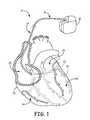
- FIG. 1is a schematic view of a cardiac rhythm management system including a pulse generator coupled to a lead deployed in a patient's heart.
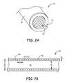
- FIG. 2Ais a perspective view of a conductor assembly including a unifilar conductive coil and a polymer sheath according to an embodiment of the present invention.
- FIG. 2Bis a cross-sectional view of the conductor assembly shown in FIG. 2A .
- FIG. 3Ais a cross-sectional view of a conductor assembly including a partially ablated polymer sheath according to another embodiment of the present invention.
- FIG. 3Bis a plan view of the conductor assembly shown in FIG. 3A .
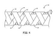
- FIG. 4is a plan view of a conductor assembly including a polymer sheath ablated with a stent like pattern according to another embodiment of the present invention.
- FIG. 1is a schematic view of a cardiac rhythm management system 10 including an implantable medical device (IMD) 12 with a lead 14 having a proximal end 16 and a distal end 18 .
- the IMD 12includes a pulse generator such as a pacemaker or a defibrillator.
- the IMD 12can be implanted subcutaneously within the body, typically at a location such as in the patient's chest or abdomen, although other implantation locations are possible.
- the proximal end 16 of the lead 14can be coupled to or formed integrally with the IMD 12 .
- the distal end 18 of the lead 14in turn, can be implanted at a desired location in or near the heart 20 .
- a distal portion of the lead 14is disposed in a patient's heart 20 , which includes a right atrium 22 , a right ventricle 24 , a left atrium 26 , and a left ventricle 28 .
- the distal end 18 of the lead 14is transvenously guided through the right atrium 22 , through the coronary sinus ostium 29 , and into a branch of the coronary sinus 31 or the great cardiac vein 33 .
- the illustrated position of the lead 14can be used for sensing or for delivering pacing and/or defibrillation energy to the left side of the heart 20 , or to treat arrhythmias or other cardiac disorders requiring therapy delivered to the left side of the heart 20 . Additionally, it will be appreciated that the lead 14 can also be used to provide treatment in other regions of the heart 20 (e.g., the right ventricle 24 ).
- the illustrative embodimentdepicts only a single implanted lead 14 , it should be understood that multiple leads can be utilized so as to electrically stimulate other areas of the heart 20 .
- the distal end of a second leadmay be implanted in the right atrium 22
- the distal end of a third leadmay be implanted in the right ventricle 24 .
- Other types of leadssuch as epicardial leads may also be utilized in addition to, or in lieu of, the lead 14 depicted in FIG. 1 .
- the lead 14can be configured to convey electrical signals between the IMD 12 and the heart 20 .
- the lead 14can be utilized to deliver electrical stimuli for pacing the heart 20 .
- the lead 14can be utilized to deliver electric shocks to the heart 20 in response to an event such as a heart attack or arrhythmia.
- the IMD 12includes both pacing and defibrillation capabilities.
- the electrical signalsare carried between the IMD 12 and electrodes at the distal end 18 by one or more conductors extending through the lead 14 .
- the one or more conductorsare electrically coupled to a connector suitable for interfacing with the IMD 12 at the proximal end 16 of the lead 14 , and to one or more electrodes at the distal end 18 .
- the one or more conductorsare helically coiled including a plurality of turns having a coil pitch and an outer diameter and consisting of one filar having a filar diameter.
- the coil pitch and outer diameterare selected based on the filar diameter to minimize effects of magnetic resonance imaging (MRI) scans on the functionality and operation of the lead 14 .
- MRImagnetic resonance imaging
- a polymer sheathis formed about the helically coiled conductor such that the coil pitch of the unifilar helically coiled conductor is maintained.
- the polymer sheathis also configured to increase a torque transmitting capacity of the helically coiled conductor.
- FIG. 2Ais a perspective view
- FIG. 2Bis a cross-sectional view, of a conductor assembly 50 according to the present invention.
- the conductor assembly 50extends through the interior of the lead 14 and includes a coil 52 and a polymer sheath 54 .
- the coil 52is coupled to the IMD 12 via a connector at the proximal end 16 of the lead 14 and to one or more electrodes at the distal end 18 of the lead 14 . While a single coil 52 is shown in FIG. 2A and FIG. 2B , the conductor assembly 50 can be configured to included multiple coils 52 each capable of delivering signals between the IMD 12 and the electrodes at the distal end 18 .
- the coil 52includes a single filar 56 that is helically wound around a longitudinal axis of the conductor assembly 50 .
- the filar 56has a diameter d.
- a lumen 58extends through the center of the coil 52 and is suitable for receiving a tool to deliver the lead 14 , such as a guidewire or stent.
- the coil 52includes a plurality of turns having an outer diameter OD and an inner diameter ID.
- the coil 52also has a coil pitch p that extends from the center of a turn of the coil 52 to the center of an adjacent turn of the coil 52 .
- Exposure of the lead 14 to magnetic resonance imaging (MRI) fieldscan result in localized heating of the electrodes at the distal end 18 due to excitation of the lead conductors (e.g., coil 52 ).
- Conductors with high inductanceare more resistant to excitation in MRI fields.
- the inductance of the conductoris determined by its geometric properties, including whether the conductor is straight or coiled.
- a coiled or wound conductorsuch as the coil 52 , several parameters influence its inductance, including the coil pitch p, the outer diameter OD, the cross-sectional area of the coil 52 , and the number of filars comprising the coil.
- the dimensions of the coil 52may be selected to minimize the effects of magnetic resonance imaging (MRI) fields on the performance and response of the lead 14 .
- MRImagnetic resonance imaging
- a coil pitch p in the range of one to about two times the filar diameter d, and an outer diameter OD at least about 4.5 times the coil pitch pincreases the inductance of the coil sufficiently to minimize the energy picked up by the coil 52 .
- Table 1 belowprovides example dimensions for the coil 52 to minimize electrode heating caused by MRI fields.
- the listed dimensionsare for a coil 52 having a length (extending from the connector to the distal end 18 ) in the range of about 450 mm to about 600 mm.
- the listed dimensions for the filar diameter d, coil pitch p, and coil outer diameter ODare only by way of example, and other dimensions that reduce electrode heating due to MRI fields to suitable levels are also contemplated. In addition, for embodiments of the conductor assembly 50 including multiple coaxial unifilar coils, these dimensions may change to account for the interaction of the coils with each other in the presence of an MRI field.
- the coil 52 with a small diameter OD and having a small pitch pmay be prone to damage during construction and use.
- the coil 52is intended to rotate relative to the lead body and drive torque to extend the fixation helix into tissue of the heart 20 .
- Unifilar coils, such as coil 52often do not conduct torque well, and the forces typically encountered by the lead 14 can cause the coil 52 to experience stress concentrations in portions of the coil 52 , which can lead to premature fatigue of the coil 52 .
- the polymer sheath 54is formed around the coil 52 such that the polymer sheath 54 covers or envelops the coil 52 .
- the polymer sheath 54may be formed over the coil 52 such that portions of the polymer sheath 54 extend between turns of the coil 52 to maintain proper spacing of the coil turns with respect to each other.
- the polymer sheath 54is a sleeve that is pulled over the coil 52 during manufacture.
- the polymer sheath 54is extruded over, molded around, adhered to, or heat shrunk over the coil 52 .
- the polymer sheath 54may be formed over a coil 52 with an open lumen 58 .
- the coil 52may be coiled around a tube or cylinder of insulative material, and the polymer sheath 54 subsequently formed around the coil 52 .
- the polymer sheath 54is thick enough and is comprised of a material that is stiff enough to increase the torque transmission capacity and maintain the coil pitch p of the coil 52 , while still allowing the conductor assembly 50 to sufficiently flex during use.
- the thickness t of the polymer sheath 54is less than about 0.002 inch and is made of a material selected from the group consisting of expanded polytetrafluoroethylene (ePTFE), layered ePTFE, polytetrafluoroethylene (PTFE), ethylene/tetrafluoroethylene copolymer (ETFE), fluorinated ethylene propylene (FEP), silicone, polyurethane, silicone-polyurethane copolymer, and a porous polymer. It will be appreciated that other materials and other thicknesses t are also possible.
- the polymer sheath 54may be adhered to portions of the coil 52 to prevent the polymer sheath 54 from delaminating from the coil 52 . Often, this may be accomplished by applying an adhesive material to the coil 52 prior to forming the polymer sheath 54 thereon. However, in some cases, the material used for the polymer sheath 54 does not adhere well to the material used for the coil 52 .
- the coil 52may be coated with a material that bonds well with the polymer sheath 54 .
- the filar 56may be coated in a suitable polymer prior to coiling the filar 56 into coil 52 .
- the coil 52may be etched, such as via laser etching, with a pattern that allows for good bonding with the polymer sheath 54 .
- portions of the polymer sheath 54may be modified to increase the flexibility of the polymer sheath 54 .
- the leadin a J-shaped lead, the lead has a sharp bend at the location of the J-shaped portion. The interaction between certain materials for the polymer sheath 54 and the conductive coil 52 at this sharp bend may cause the conductor assembly 50 to remain in the J-shape, which may prevent manipulation of the J-shaped portion during implantation.
- FIG. 3Ais a cross-sectional view and FIG. 3B is a plan view of a conductor assembly 60 according to another embodiment of the present invention that includes features that improve the flexibility of the conductor assembly 60 .
- the conductor assembly 60includes a coil 62 and a polymer sheath 64 having material and dimension characteristics substantially similar to the coil 52 and polymer sheath 54 , respectively, discussed above with regard to FIGS. 2A and 2B .
- the polymer sheath 64is partially ablated with an ablation pattern 70 along a length of at least a portion of the conductor assembly 60 .
- the polymer sheath 64is partially ablated in that the polymer sheath 64 is not completely removed (i.e., the coil 52 is not exposed) at the ablated portions of the polymer sheath 64 .
- the polymer sheath 64may be partially ablated along the inner radius of the sharp bend at the J-shaped portion. While improving the flexibility of the conductor assembly 60 , the remaining thickness of the polymer sheath 64 at the partially ablated locations serve to maintain the pitch p of the coil 62 and improve the torque transmission capacity of the coil 62 .
- the ablation pattern 70is a spiral pattern that winds around polymer sheath 64 , and about 20% of the polymer sheath 64 is partially ablated.
- the ablation pattern 70may comprise any form, and any percentage of the polymer sheath 64 may be partially ablated, to improve the flexibility of the conductor assembly 60 while maintaining the coil pitch p and improving the torque transmission capacity of the conductor assembly 60 .
- the polymer sheath 64may be partially ablated with the ablation pattern 70 using a variety of techniques. In some embodiments, an unmodified polymer sheath 64 is formed over the coil 62 and subsequently modified into the desired pattern.
- the ablation pattern 70may be formed by, for example, laser ablating the ablation pattern 70 into the polymer sheath 64 .
- the ablation pattern 70may alternatively be formed by etching or grinding the ablation pattern 70 into the polymer sheath 64 .
- FIG. 4is a plan view of a conductor assembly 80 according to another embodiment of the present invention.
- the conductor assembly 80includes a coil 82 and a polymer sheath 84 having material and dimension characteristics substantially similar to the coil 52 and polymer sheath 54 , respectively, discussed above with regard to FIGS. 2A and 2B .
- the polymer sheath 84is ablated with a stent-like pattern 90 along a length of at least a portion of the conductor assembly 80 .
- the stent-like pattern 90includes substantially diamond-shaped ablated portions 92 and unablated portions 94 .
- the ablated portions 92are partial ablations that do not extend completely through the thickness t of the polymer sheath 84 .
- the ablated portions 92are ablated completely through the thickness t of the polymer sheath 84 .
- the present inventionrelates to a conductor assembly for a medical device lead that includes a helically coiled conductor including a plurality of turns having a coil pitch and an outer diameter and consisting of one filar having a filar diameter.
- the coil pitch and outer diameterare selected based on the filar diameter to minimize heating of the helically coiled conductor in the presence of an MRI field.
- the coil pitchis one to about two times the filar diameter
- the outer diameteris at least 4.5 times the coil pitch.
- a polymer sheathis formed about the helically coiled conductor such that the coil pitch of the unifilar helically coiled conductor is maintained.
- the polymer sheathis configured to increase a torque transmitting capacity of the helically coiled conductor.
- the polymer sheathis partially ablated in a pattern along a length of the polymer sheath that enhances the torque transmitting capacity of the helically coiled conductor.
- the medical device leadincludes an insulated lead body including at least one electrode, and the helically coiled conductor is electrically coupled to the at least one electrode.
Landscapes
- Health & Medical Sciences (AREA)
- Heart & Thoracic Surgery (AREA)
- Nuclear Medicine, Radiotherapy & Molecular Imaging (AREA)
- Cardiology (AREA)
- Engineering & Computer Science (AREA)
- Biomedical Technology (AREA)
- Radiology & Medical Imaging (AREA)
- Life Sciences & Earth Sciences (AREA)
- Animal Behavior & Ethology (AREA)
- General Health & Medical Sciences (AREA)
- Public Health (AREA)
- Veterinary Medicine (AREA)
- Vascular Medicine (AREA)
- Electrotherapy Devices (AREA)
Abstract
Description
This application is a continuation of U.S. patent application Ser. No. 12/774,170, filed May 5, 2010, which claims priority to Provisional Application No. 61/220,658, filed Jun. 26, 2009, which is herein incorporated by reference in its entirety.
The present invention relates to implantable medical devices. More particularly, the present invention relates to medical device lead constructions including a unifilar coil with a polymer coating.
Implantable medical devices for treating a variety of medical conditions with electrical stimuli are well known. Implantable medical devices generally include a medical electrical lead for delivering an electrical stimulus to a targeted site within a patient's body such as, for example, a patient's heart or nervous system. Such leads generally have an elongated, flexible insulating body, one or more inner conductors extending through lumens formed in the body and one or more exposed electrodes connected to the distal ends of the conductors.
Leads may be introduced into the patient's vasculature at a venous access site and transvenously guided through veins to the sites where the lead electrodes will be implanted or otherwise contact tissue at the targeted therapy site. A pulse generator attached to the proximal ends of the conductors delivers an electrical stimulus therapy to the targeted site via the one or more conductors.
The present disclosure relates to a medical device lead including an electrode, a helically coiled conductor electrically coupled to the electrode, and a polymer sheath formed over the helically coiled conductor. The helically coiled conductor includes a plurality of turns helically wound around a longitudinal axis of the conductor, and consists of one filar.
In another aspect, the present disclosure relates to a medical device lead including an electrode and a helically coiled conductor electrically coupled to the electrode. The helically coiled conductor includes a plurality of turns helically wound around a longitudinal axis of the conductor assembly. The helically coiled conductor has a coil pitch and an outer diameter and consists of one filar having a filar diameter. The coil pitch and outer diameter are selected based on the filar diameter to minimize heating of the helically coiled conductor in the presence of an MRI field. A polymer sheath is formed over the helically coiled conductor.
In a further aspect, the present disclosure relates to a conductor assembly for a medical device lead. The conductor assembly includes a helically coiled conductor configured to be coupled to a pulse generator at a proximal end and an electrode at a distal end. The helically coiled conductor includes a plurality of turns helically wound around a longitudinal axis of the conductor assembly. The helically coiled conductor consists of one filar. The conductor assembly further includes a polymer sheath formed over the helically coiled conductor.
While multiple embodiments are disclosed, still other embodiments of the present invention will become apparent to those skilled in the art from the following detailed description, which shows and describes illustrative embodiments of the invention. Accordingly, the drawings and detailed description are to be regarded as illustrative in nature and not restrictive.
While the invention is amenable to various modifications and alternative forms, specific embodiments have been shown by way of example in the drawings and are described in detail below. The intention, however, is not to limit the invention to the particular embodiments described. On the contrary, the invention is intended to cover all modifications, equivalents, and alternatives falling within the scope of the invention as defined by the appended claims.
As shown inFIG. 1 , a distal portion of thelead 14 is disposed in a patient'sheart 20, which includes aright atrium 22, aright ventricle 24, aleft atrium 26, and aleft ventricle 28. In the embodiment illustrated inFIG. 1 , thedistal end 18 of thelead 14 is transvenously guided through theright atrium 22, through thecoronary sinus ostium 29, and into a branch of thecoronary sinus 31 or the great cardiac vein33. The illustrated position of thelead 14 can be used for sensing or for delivering pacing and/or defibrillation energy to the left side of theheart 20, or to treat arrhythmias or other cardiac disorders requiring therapy delivered to the left side of theheart 20. Additionally, it will be appreciated that thelead 14 can also be used to provide treatment in other regions of the heart20 (e.g., the right ventricle24).
Although the illustrative embodiment depicts only a single implantedlead 14, it should be understood that multiple leads can be utilized so as to electrically stimulate other areas of theheart 20. In some embodiments, for example, the distal end of a second lead (not shown) may be implanted in theright atrium 22, and/or the distal end of a third lead (not shown) may be implanted in theright ventricle 24. Other types of leads such as epicardial leads may also be utilized in addition to, or in lieu of, thelead 14 depicted inFIG. 1 .
During operation, thelead 14 can be configured to convey electrical signals between theIMD 12 and theheart 20. For example, in those embodiments where the IMD12 is a pacemaker, thelead 14 can be utilized to deliver electrical stimuli for pacing theheart 20. In those embodiments where the IMD12 is an implantable cardiac defibrillator, thelead 14 can be utilized to deliver electric shocks to theheart 20 in response to an event such as a heart attack or arrhythmia. In some embodiments, the IMD12 includes both pacing and defibrillation capabilities.
The electrical signals are carried between theIMD 12 and electrodes at thedistal end 18 by one or more conductors extending through thelead 14. The one or more conductors are electrically coupled to a connector suitable for interfacing with theIMD 12 at theproximal end 16 of thelead 14, and to one or more electrodes at thedistal end 18. According to the present invention, the one or more conductors are helically coiled including a plurality of turns having a coil pitch and an outer diameter and consisting of one filar having a filar diameter. The coil pitch and outer diameter are selected based on the filar diameter to minimize effects of magnetic resonance imaging (MRI) scans on the functionality and operation of thelead 14. A polymer sheath is formed about the helically coiled conductor such that the coil pitch of the unifilar helically coiled conductor is maintained. The polymer sheath is also configured to increase a torque transmitting capacity of the helically coiled conductor.
Thecoil 52 includes asingle filar 56 that is helically wound around a longitudinal axis of theconductor assembly 50. The filar56 has a diameter d. Alumen 58 extends through the center of thecoil 52 and is suitable for receiving a tool to deliver thelead 14, such as a guidewire or stent. Thecoil 52 includes a plurality of turns having an outer diameter OD and an inner diameter ID. Thecoil 52 also has a coil pitch p that extends from the center of a turn of thecoil 52 to the center of an adjacent turn of thecoil 52.
Exposure of thelead 14 to magnetic resonance imaging (MRI) fields can result in localized heating of the electrodes at thedistal end 18 due to excitation of the lead conductors (e.g., coil52). Conductors with high inductance (>1 μH) are more resistant to excitation in MRI fields. The inductance of the conductor is determined by its geometric properties, including whether the conductor is straight or coiled. For a coiled or wound conductor, such as thecoil 52, several parameters influence its inductance, including the coil pitch p, the outer diameter OD, the cross-sectional area of thecoil 52, and the number of filars comprising the coil. Thus, the dimensions of thecoil 52 may be selected to minimize the effects of magnetic resonance imaging (MRI) fields on the performance and response of thelead 14. For example, for aconductor assembly 50 as shown including a single,unifilar coil 52, a coil pitch p in the range of one to about two times the filar diameter d, and an outer diameter OD at least about 4.5 times the coil pitch p increases the inductance of the coil sufficiently to minimize the energy picked up by thecoil 52.
Table 1 below provides example dimensions for thecoil 52 to minimize electrode heating caused by MRI fields. The listed dimensions are for acoil 52 having a length (extending from the connector to the distal end18) in the range of about 450 mm to about 600 mm.
| TABLE 1 | ||||
| Filar Diameter (d) | Coil Pitch (p) | Coil Outer Diameter (OD) | ||
| (inch) | (inch) | (inch) | ||
| 0.0005 | 0.0005-0.0008 | 0.002 | ||
| 0.001 | 0.001-0.002 | 0.004 | ||
| 0.002 | 0.002-0.003 | 0.009 | ||
| 0.003 | 0.003-0.004 | 0.013 | ||
| 0.004 | 0.004-0.005 | 0.020 | ||
| 0.005 | 0.005-0.007 | 0.022 | ||
| 0.006 | 0.006-0.008 | 0.027 | ||
| 0.007 | 0.007-0.009 | 0.031 | ||
| 0.008 | 0.008-0.010 | 0.036 | ||
| 0.009 | 0.009-0.011 | 0.040 | ||
| 0.010 | 0.010-0.012 | 0.045 | ||
| 0.011 | 0.011-0.013 | 0.049 | ||
These dimensions are suitable for a
Thecoil 52 with a small diameter OD and having a small pitch p may be prone to damage during construction and use. For example, in active fixation leads, thecoil 52 is intended to rotate relative to the lead body and drive torque to extend the fixation helix into tissue of theheart 20. Unifilar coils, such ascoil 52, often do not conduct torque well, and the forces typically encountered by thelead 14 can cause thecoil 52 to experience stress concentrations in portions of thecoil 52, which can lead to premature fatigue of thecoil 52. In order to improve the torque transmitting capacity of thecoil 52, as well as to maintain the integrity of the coil pitch p, thepolymer sheath 54 is formed around thecoil 52 such that thepolymer sheath 54 covers or envelops thecoil 52.
Thepolymer sheath 54 may be formed over thecoil 52 such that portions of thepolymer sheath 54 extend between turns of thecoil 52 to maintain proper spacing of the coil turns with respect to each other. In some embodiments, thepolymer sheath 54 is a sleeve that is pulled over thecoil 52 during manufacture. In other embodiments, thepolymer sheath 54 is extruded over, molded around, adhered to, or heat shrunk over thecoil 52. Thepolymer sheath 54 may be formed over acoil 52 with anopen lumen 58. Alternatively, thecoil 52 may be coiled around a tube or cylinder of insulative material, and thepolymer sheath 54 subsequently formed around thecoil 52.
Thepolymer sheath 54 is thick enough and is comprised of a material that is stiff enough to increase the torque transmission capacity and maintain the coil pitch p of thecoil 52, while still allowing theconductor assembly 50 to sufficiently flex during use. In some embodiments, the thickness t of thepolymer sheath 54 is less than about 0.002 inch and is made of a material selected from the group consisting of expanded polytetrafluoroethylene (ePTFE), layered ePTFE, polytetrafluoroethylene (PTFE), ethylene/tetrafluoroethylene copolymer (ETFE), fluorinated ethylene propylene (FEP), silicone, polyurethane, silicone-polyurethane copolymer, and a porous polymer. It will be appreciated that other materials and other thicknesses t are also possible.
Thepolymer sheath 54 may be adhered to portions of thecoil 52 to prevent thepolymer sheath 54 from delaminating from thecoil 52. Often, this may be accomplished by applying an adhesive material to thecoil 52 prior to forming thepolymer sheath 54 thereon. However, in some cases, the material used for thepolymer sheath 54 does not adhere well to the material used for thecoil 52. In order to assure good adhesion, thecoil 52 may be coated with a material that bonds well with thepolymer sheath 54. For example, the filar56 may be coated in a suitable polymer prior to coiling the filar56 intocoil 52. Alternatively, thecoil 52 may be etched, such as via laser etching, with a pattern that allows for good bonding with thepolymer sheath 54.
In some cases, portions of thepolymer sheath 54 may be modified to increase the flexibility of thepolymer sheath 54. For example, in a J-shaped lead, the lead has a sharp bend at the location of the J-shaped portion. The interaction between certain materials for thepolymer sheath 54 and theconductive coil 52 at this sharp bend may cause theconductor assembly 50 to remain in the J-shape, which may prevent manipulation of the J-shaped portion during implantation.
In the embodiment shown, theablation pattern 70 is a spiral pattern that winds aroundpolymer sheath 64, and about 20% of thepolymer sheath 64 is partially ablated. However, it will be appreciated that theablation pattern 70 may comprise any form, and any percentage of thepolymer sheath 64 may be partially ablated, to improve the flexibility of theconductor assembly 60 while maintaining the coil pitch p and improving the torque transmission capacity of theconductor assembly 60.
Thepolymer sheath 64 may be partially ablated with theablation pattern 70 using a variety of techniques. In some embodiments, anunmodified polymer sheath 64 is formed over thecoil 62 and subsequently modified into the desired pattern. Theablation pattern 70 may be formed by, for example, laser ablating theablation pattern 70 into thepolymer sheath 64. Theablation pattern 70 may alternatively be formed by etching or grinding theablation pattern 70 into thepolymer sheath 64.
In summary, the present invention relates to a conductor assembly for a medical device lead that includes a helically coiled conductor including a plurality of turns having a coil pitch and an outer diameter and consisting of one filar having a filar diameter. The coil pitch and outer diameter are selected based on the filar diameter to minimize heating of the helically coiled conductor in the presence of an MRI field. In some embodiments, the coil pitch is one to about two times the filar diameter, and the outer diameter is at least 4.5 times the coil pitch. A polymer sheath is formed about the helically coiled conductor such that the coil pitch of the unifilar helically coiled conductor is maintained. The polymer sheath is configured to increase a torque transmitting capacity of the helically coiled conductor. In some embodiments, the polymer sheath is partially ablated in a pattern along a length of the polymer sheath that enhances the torque transmitting capacity of the helically coiled conductor. In one exemplary embodiment, the medical device lead includes an insulated lead body including at least one electrode, and the helically coiled conductor is electrically coupled to the at least one electrode.
Various modifications and additions can be made to the exemplary embodiments discussed without departing from the scope of the present invention. For example, while the embodiments described above refer to particular features, the scope of this invention also includes embodiments having different combinations of features and embodiments that do not include all of the described features. Accordingly, the scope of the present invention is intended to embrace all such alternatives, modifications, and variations as fall within the scope of the claims, together with all equivalents thereof.
Claims (22)
1. A medical device lead comprising:
an electrode;
a helically coiled conductor electrically coupled to the electrode, the helically coiled conductor including a plurality of turns helically wound around a longitudinal axis of the conductor, wherein the helically coiled conductor consists of one filar; and
a polymer sheath formed over the helically coiled conductor.
2. The medical device lead ofclaim 1 , wherein the helically coiled conductor has a coil pitch and an outer diameter, wherein the filar has a filar diameter, and wherein the coil pitch is one to about two times the filar diameter and the outer diameter is at least 4.5 times the coil pitch.
3. The medical device lead ofclaim 1 , wherein the polymer sheath is partially ablated in a pattern along a length of the polymer sheath to increase the flexibility of the conductor assembly around the partial ablation.
4. The medical device lead ofclaim 1 , wherein the helically coiled conductor is adapted to promote adhesion with the polymer sheath.
5. The medical device lead ofclaim 3 , wherein the helically coiled conductor is coated in a material that promotes adhesion between the polymer sheath and the helically coiled conductor.
6. The medical device lead ofclaim 3 , wherein a surface of the helically coiled conductor is etched to promote adhesion with the polymer sheath.
7. The medical device lead ofclaim 1 , wherein the polymer sheath is comprised of a material selected from the group consisting of expanded polytetrafluoroethylene (ePTFE), layered ePTFE, polytetrafluoroethylene (PTFE), ethylene/tetrafluoroethylene copolymer (ETFE), fluorinated ethylene propylene (FEP), silicone, polyurethane, silicone-polyurethane copolymer, and a porous polymer.
8. The medical device lead ofclaim 1 , wherein a thickness of the polymer sheath is less than about 0.002 inch (0.051 mm).
9. A medical device lead comprising:
an electrode;
a helically coiled conductor electrically coupled to the electrode, the helically coiled conductor including a plurality of turns helically wound around a longitudinal axis of the conductor assembly, the helically coiled conductor having a coil pitch and an outer diameter and consisting of one filar having a filar diameter, wherein the coil pitch and outer diameter are selected based on the filar diameter to minimize heating of the helically coiled conductor in the presence of an MRI field; and
a polymer sheath formed over the helically coiled conductor.
10. The medical device lead ofclaim 9 , wherein the coil pitch is one to about two times the filar diameter.
11. The medical device lead ofclaim 9 , wherein the outer diameter is at least 4.5 times the coil pitch.
12. The medical device lead ofclaim 9 , wherein the polymer sheath is partially ablated in a pattern along a length of the polymer sheath such that a thickness of the polymer sheath along the partially ablated pattern is less than a thickness of non-ablated portions of the polymer sheath.
13. The medical device lead ofclaim 9 , wherein the helically coiled conductor is adapted to promote adhesion with the polymer sheath.
14. The medical device lead ofclaim 13 , wherein the helically coiled conductor is coated in a material that promotes adhesion between the polymer sheath and the helically coiled conductor.
15. The medical device lead ofclaim 13 , wherein a surface of the helically coiled conductor is etched to promote adhesion with the polymer sheath.
16. The medical device lead ofclaim 9 , wherein the polymer sheath is comprised of a material selected from the group consisting of expanded polytetrafluoroethylene (ePTFE), layered ePTFE, polytetrafluoroethylene (PTFE), ethylene/tetrafluoroethylene copolymer (ETFE), fluorinated ethylene propylene (FEP), silicone, polyurethane, silicone-polyurethane copolymer, and a porous polymer.
17. A conductor assembly for a medical device lead, the conductor assembly comprising:
a helically coiled conductor configured to be coupled to a pulse generator at a proximal end and an electrode at a distal end, the helically coiled conductor including a plurality of turns helically wound around a longitudinal axis of the conductor assembly, wherein the helically coiled conductor consists of one filar; and
a polymer sheath formed over the helically coiled conductor.
18. The conductor assembly ofclaim 17 , wherein the helically coiled conductor has a coil pitch and an outer diameter, wherein the filar has a filar diameter, and wherein the coil pitch is one to about two times the filar diameter and the outer diameter is at least 4.5 times the coil pitch.
19. The conductor assembly ofclaim 17 , wherein the polymer sheath is partially ablated in a pattern along a length of the polymer sheath to increase the flexibility of the conductor assembly around the partial ablation.
20. The conductor assembly ofclaim 17 , wherein the helically coiled conductor is coated in a material that promotes adhesion between the polymer sheath and the helically coiled conductor.
21. The conductor assembly ofclaim 17 , wherein a surface of the helically coiled conductor is etched to promote adhesion with the polymer sheath.
22. The conductor assembly ofclaim 17 , wherein the polymer sheath is comprised of a material selected from the group consisting of expanded polytetrafluoroethylene (ePTFE), layered ePTFE, polytetrafluoroethylene (PTFE), ethylene/tetrafluoroethylene copolymer (ETFE), fluorinated ethylene propylene (FEP), silicone, polyurethane, silicone-polyurethane copolymer, and a porous polymer.
Priority Applications (1)
| Application Number | Priority Date | Filing Date | Title |
|---|---|---|---|
| US13/665,223US8744600B2 (en) | 2009-06-26 | 2012-10-31 | Medical device lead including a unifilar coil with improved torque transmission capacity and reduced MRI heating |
Applications Claiming Priority (3)
| Application Number | Priority Date | Filing Date | Title |
|---|---|---|---|
| US22065809P | 2009-06-26 | 2009-06-26 | |
| US12/774,170US8332050B2 (en) | 2009-06-26 | 2010-05-05 | Medical device lead including a unifilar coil with improved torque transmission capacity and reduced MRI heating |
| US13/665,223US8744600B2 (en) | 2009-06-26 | 2012-10-31 | Medical device lead including a unifilar coil with improved torque transmission capacity and reduced MRI heating |
Related Parent Applications (1)
| Application Number | Title | Priority Date | Filing Date |
|---|---|---|---|
| US12/774,170ContinuationUS8332050B2 (en) | 2009-06-26 | 2010-05-05 | Medical device lead including a unifilar coil with improved torque transmission capacity and reduced MRI heating |
Related Child Applications (1)
| Application Number | Title | Priority Date | Filing Date |
|---|---|---|---|
| US14/629,241ContinuationUS9616693B2 (en) | 2011-11-30 | 2015-02-23 | Printing control apparatus, control method thereof, and storage medium |
Publications (2)
| Publication Number | Publication Date |
|---|---|
| US20130190849A1 US20130190849A1 (en) | 2013-07-25 |
| US8744600B2true US8744600B2 (en) | 2014-06-03 |
Family
ID=42352175
Family Applications (2)
| Application Number | Title | Priority Date | Filing Date |
|---|---|---|---|
| US12/774,170Expired - Fee RelatedUS8332050B2 (en) | 2009-06-26 | 2010-05-05 | Medical device lead including a unifilar coil with improved torque transmission capacity and reduced MRI heating |
| US13/665,223ActiveUS8744600B2 (en) | 2009-06-26 | 2012-10-31 | Medical device lead including a unifilar coil with improved torque transmission capacity and reduced MRI heating |
Family Applications Before (1)
| Application Number | Title | Priority Date | Filing Date |
|---|---|---|---|
| US12/774,170Expired - Fee RelatedUS8332050B2 (en) | 2009-06-26 | 2010-05-05 | Medical device lead including a unifilar coil with improved torque transmission capacity and reduced MRI heating |
Country Status (7)
| Country | Link |
|---|---|
| US (2) | US8332050B2 (en) |
| EP (1) | EP2445577B1 (en) |
| JP (1) | JP5542926B2 (en) |
| CN (1) | CN102802723B (en) |
| AU (1) | AU2010263218B2 (en) |
| ES (1) | ES2547713T3 (en) |
| WO (1) | WO2010151376A1 (en) |
Cited By (8)
| Publication number | Priority date | Publication date | Assignee | Title |
|---|---|---|---|---|
| US8958889B2 (en) | 2012-08-31 | 2015-02-17 | Cardiac Pacemakers, Inc. | MRI compatible lead coil |
| US9050457B2 (en) | 2009-12-31 | 2015-06-09 | Cardiac Pacemakers, Inc. | MRI conditionally safe lead with low-profile conductor for longitudinal expansion |
| US9199077B2 (en) | 2009-12-31 | 2015-12-01 | Cardiac Pacemakers, Inc. | MRI conditionally safe lead with multi-layer conductor |
| US9333344B2 (en) | 2012-06-01 | 2016-05-10 | Cardiac Pacemakers, Inc. | Implantable device lead including a distal electrode assembly with a coiled component |
| US9504822B2 (en) | 2012-10-18 | 2016-11-29 | Cardiac Pacemakers, Inc. | Inductive element for providing MRI compatibility in an implantable medical device lead |
| US9504821B2 (en) | 2014-02-26 | 2016-11-29 | Cardiac Pacemakers, Inc. | Construction of an MRI-safe tachycardia lead |
| US9750944B2 (en) | 2009-12-30 | 2017-09-05 | Cardiac Pacemakers, Inc. | MRI-conditionally safe medical device lead |
| DE102019106675A1 (en) | 2018-03-20 | 2019-09-26 | Biotronik Se & Co. Kg | Lead for a medical implant, with integrated periodic induction coils (iPIC) for reduced interactions with electromagnetic fields |
Families Citing this family (23)
| Publication number | Priority date | Publication date | Assignee | Title |
|---|---|---|---|---|
| US7610101B2 (en) | 2006-11-30 | 2009-10-27 | Cardiac Pacemakers, Inc. | RF rejecting lead |
| AU2008335462B2 (en) | 2007-12-06 | 2014-02-20 | Cardiac Pacemakers, Inc. | Implantable lead having a variable coil conductor pitch |
| WO2009100003A1 (en) | 2008-02-06 | 2009-08-13 | Cardiac Pacemakers, Inc. | Lead with mri compatible design features |
| US8103360B2 (en) | 2008-05-09 | 2012-01-24 | Foster Arthur J | Medical lead coil conductor with spacer element |
| US9084883B2 (en) | 2009-03-12 | 2015-07-21 | Cardiac Pacemakers, Inc. | Thin profile conductor assembly for medical device leads |
| ES2547713T3 (en) | 2009-06-26 | 2015-10-08 | Cardiac Pacemakers, Inc. | Bypass of a medical device that includes a single-coil coil with improved torque transmission capacity and reduced RM heating |
| US8335572B2 (en) | 2009-10-08 | 2012-12-18 | Cardiac Pacemakers, Inc. | Medical device lead including a flared conductive coil |
| US9254380B2 (en) | 2009-10-19 | 2016-02-09 | Cardiac Pacemakers, Inc. | MRI compatible tachycardia lead |
| US20120004714A1 (en)* | 2010-06-30 | 2012-01-05 | Ryan Kleve | Lead having coil electrode with preferential bending region |
| US8825181B2 (en) | 2010-08-30 | 2014-09-02 | Cardiac Pacemakers, Inc. | Lead conductor with pitch and torque control for MRI conditionally safe use |
| JP2014511752A (en)* | 2011-04-20 | 2014-05-19 | カーディアック ペースメイカーズ, インコーポレイテッド | Ultrasound monitoring of implantable medical devices |
| US8666512B2 (en) | 2011-11-04 | 2014-03-04 | Cardiac Pacemakers, Inc. | Implantable medical device lead including inner coil reverse-wound relative to shocking coil |
| AU2013249088B2 (en) | 2012-04-20 | 2015-12-03 | Cardiac Pacemakers, Inc. | Implantable medical device lead including a unifilar coiled cable |
| JP2013232356A (en)* | 2012-04-27 | 2013-11-14 | Junkosha Co Ltd | Coiled cable |
| US20140046415A1 (en)* | 2012-08-09 | 2014-02-13 | Cardiac Pacemakers, Inc. | Reinforced coil created from polymer coated wire for improved torque transfer |
| US9295808B2 (en) | 2012-08-14 | 2016-03-29 | Cardiac Pacemakers, Inc. | Medical device with textured surface |
| AU2013303074B2 (en) | 2012-08-14 | 2015-12-17 | Cardiac Pacemakers, Inc. | Lead with an inner conductor provided with a textured insulative layer |
| US10702674B2 (en) | 2013-06-28 | 2020-07-07 | Normedix, Inc. | Braided catheter assemblies |
| CA2919458C (en) | 2013-06-28 | 2021-08-17 | Gmedix, Inc. | Introducer sheath for radial artery access |
| MX2018014179A (en)* | 2016-05-18 | 2019-08-26 | Normedix Inc | Braided catheter assemblies. |
| US11278717B2 (en) | 2017-08-29 | 2022-03-22 | Medtronic, Inc. | Implantable medical electrical lead construction and associated implant systems |
| WO2020046921A1 (en)* | 2018-08-27 | 2020-03-05 | Invuity, Inc. | Electrosurgical device, methods of making an electrosurgical device, and methods of using an electrosurgical device |
| AU2019222842A1 (en) | 2018-09-10 | 2020-03-26 | Northern Development AS | Percutaneous Lead |
Citations (190)
| Publication number | Priority date | Publication date | Assignee | Title |
|---|---|---|---|---|
| US3614692A (en) | 1970-06-02 | 1971-10-19 | Magnetech Ind Inc | Variable induction device |
| US4131759A (en) | 1977-08-10 | 1978-12-26 | United States Steel Corporation | Slip sleeve mechanism for a strength tapered caged armored electromechanical cable |
| US4135518A (en) | 1976-05-21 | 1979-01-23 | Medtronic, Inc. | Body implantable lead and electrode |
| US4404125A (en) | 1981-10-14 | 1983-09-13 | General Electric Company | Polyphenylene ether resin compositions for EMI electromagnetic interference shielding |
| US4484586A (en) | 1982-05-27 | 1984-11-27 | Berkley & Company, Inc. | Hollow conductive medical tubing |
| US4493329A (en) | 1982-08-19 | 1985-01-15 | Lynn Crawford | Implantable electrode having different stiffening and curvature maintaining characteristics along its length |
| US4643203A (en) | 1982-07-01 | 1987-02-17 | Molins Plc | Conveying and uniting rod-like articles of the tobacco industry |
| US4869970A (en) | 1986-07-14 | 1989-09-26 | Shipley Company Inc. | Radiation attenuation shielding |
| US5056516A (en) | 1989-11-02 | 1991-10-15 | Intermedics, Inc. | Implantable endocordial lead with torque-transmitting lanyard |
| US5217010A (en) | 1991-05-28 | 1993-06-08 | The Johns Hopkins University | Ecg amplifier and cardiac pacemaker for use during magnetic resonance imaging |
| US5222506A (en) | 1991-07-29 | 1993-06-29 | Medtronic, Inc. | Implantable medical lead with electrical cross-over adaptor |
| US5231996A (en) | 1992-01-28 | 1993-08-03 | Medtronic, Inc. | Removable endocardial lead |
| US5241957A (en) | 1991-11-18 | 1993-09-07 | Medtronic, Inc. | Bipolar temporary pacing lead and connector and permanent bipolar nerve wire |
| US5243911A (en) | 1990-09-18 | 1993-09-14 | Dow Robert L | Attenuator for protecting electronic equipment from undesired exposure to RF energy and/or lightning |
| US5246014A (en) | 1991-11-08 | 1993-09-21 | Medtronic, Inc. | Implantable lead system |
| US5330522A (en) | 1992-12-29 | 1994-07-19 | Siemens Pacesetter, Inc. | Ring electrode for a multilumen lead and method of constructing a multilumen lead |
| US5354327A (en) | 1993-04-07 | 1994-10-11 | Medtronic, Inc. | Conductor coil with specific ratio of torque to bending stiffness |
| US5378234A (en) | 1993-03-15 | 1995-01-03 | Pilot Cardiovascular Systems, Inc. | Coil polymer composite |
| US5387199A (en) | 1992-02-24 | 1995-02-07 | Baxter International Inc. | Polymer blends for torque transmitting catheters |
| US5425755A (en) | 1992-12-04 | 1995-06-20 | Pacesetter, Inc. | Rotatable pin, screw-in pacing and sensing lead having Teflon-coated conductor coil |
| US5456707A (en) | 1993-10-22 | 1995-10-10 | Vitatron Medical Bv | Pacing lead with improved torsion characteristics |
| US5483022A (en) | 1994-04-12 | 1996-01-09 | Ventritex, Inc. | Implantable conductor coil formed from cabled composite wire |
| WO1996006655A1 (en) | 1994-08-29 | 1996-03-07 | Angeion Corporation | Low profile defibrillation catheter |
| US5522872A (en) | 1994-12-07 | 1996-06-04 | Ventritex, Inc. | Electrode-conductor sleeve joint for cardiac lead |
| US5522875A (en) | 1994-07-28 | 1996-06-04 | Medtronic, Inc. | Medical electrical lead system having a torque transfer stylet |
| US5554139A (en) | 1993-12-24 | 1996-09-10 | Terumo Kabushiki Kaisha | Catheter |
| US5574249A (en) | 1994-07-18 | 1996-11-12 | Lindsay Audiophile Inc. | High resistivity inner shields for cabinets housing electronic circuitry |
| US5584873A (en) | 1995-05-08 | 1996-12-17 | Medtronic, Inc. | Medical lead with compression lumens |
| US5599576A (en) | 1995-02-06 | 1997-02-04 | Surface Solutions Laboratories, Inc. | Medical apparatus with scratch-resistant coating and method of making same |
| US5609622A (en) | 1993-02-01 | 1997-03-11 | W. L. Gore & Associates, Inc. | Implantable electrode with conductive polytetrafluoroethylene elecrode |
| US5618208A (en) | 1994-06-03 | 1997-04-08 | Siemens Medical Systems, Inc. | Fully insulated, fully shielded electrical connector arrangement |
| US5728149A (en) | 1995-12-20 | 1998-03-17 | Medtronic, Inc. | Integral spiral band electrode for transvenous defibrillation leads |
| US5760341A (en) | 1996-09-10 | 1998-06-02 | Medtronic, Inc. | Conductor cable for biomedical lead |
| US5800496A (en) | 1996-06-24 | 1998-09-01 | Medtronic, Inc. | Medical electrical lead having a crush resistant lead body |
| US5810887A (en) | 1996-08-23 | 1998-09-22 | Rhythm Technologies, Inc. | Temporary catheter |
| US5833715A (en) | 1992-09-03 | 1998-11-10 | Pacesetter, Inc. | Implantable stimulation lead having an advanceable therapeutic drug delivery system |
| US5935159A (en) | 1996-12-19 | 1999-08-10 | Medtronic, Inc. | Medical electrical lead |
| US5957970A (en) | 1998-02-18 | 1999-09-28 | Medtronic, Inc. | Method of fabricating a medical electrical lead |
| US5957966A (en) | 1998-02-18 | 1999-09-28 | Intermedics Inc. | Implantable cardiac lead with multiple shape memory polymer structures |
| US5968087A (en) | 1996-12-19 | 1999-10-19 | Medtronic, Inc. | Multi-component lead body for medical electrical leads |
| US6057031A (en) | 1997-08-21 | 2000-05-02 | Gfe Metalle Und Materialien Gmbh. | Plastic substrate with thin metal-containing layer |
| US6078840A (en) | 1997-04-30 | 2000-06-20 | Medtronic, Inc. | Medical electrical lead having improved fixation |
| US6083216A (en) | 1999-01-05 | 2000-07-04 | Intermedics Inc. | Bent cardiac lead with shape memory torque coil |
| US6106522A (en) | 1993-10-14 | 2000-08-22 | Ep Technologies, Inc. | Systems and methods for forming elongated lesion patterns in body tissue using straight or curvilinear electrode elements |
| US6141593A (en) | 1998-11-10 | 2000-10-31 | Intermedics Inc. | Cardiac lead with ETEE coated DBS coil |
| US6143013A (en) | 1995-04-28 | 2000-11-07 | Target Therapeutics, Inc. | High performance braided catheter |
| US6178355B1 (en) | 1997-04-29 | 2001-01-23 | Medtronic, Inc. | Intracardiac defibrillation leads |
| US6208881B1 (en) | 1998-10-20 | 2001-03-27 | Micropure Medical, Inc. | Catheter with thin film electrodes and method for making same |
| US6249708B1 (en) | 1997-08-26 | 2001-06-19 | Angeion Corporation | Fluted channel construction for a multi-conductor catheter lead |
| US6256541B1 (en) | 1998-04-17 | 2001-07-03 | Cardiac Pacemakers, Inc. | Endocardial lead having defibrillation and sensing electrodes with septal anchoring |
| US6259954B1 (en) | 1999-02-18 | 2001-07-10 | Intermedics Inc. | Endocardial difibrillation lead with strain-relief coil connection |
| US6289250B1 (en) | 1998-05-27 | 2001-09-11 | Kabushiki Kaisha Cardio-Pacing Research Laboratory | Implantable electrode lead |
| US6295476B1 (en) | 1999-11-01 | 2001-09-25 | Medtronic, Inc. | Medical lead conductor fracture visualization method and apparatus |
| US20020065544A1 (en) | 1999-11-29 | 2002-05-30 | Medtronic, Inc. | Medical electrical lead having variable bending stiffness |
| US6400992B1 (en) | 1999-03-18 | 2002-06-04 | Medtronic, Inc. | Co-extruded, multi-lumen medical lead |
| US20020072769A1 (en) | 2000-12-11 | 2002-06-13 | Sergiu Silvian | System and method of protecting transformer-driven switches from external magnetic fields |
| US20020111664A1 (en) | 1999-09-29 | 2002-08-15 | Cardiac Pacemakers, Inc. | Low profile, ventricular, transvenous, epicardial defibrillation lead |
| US20020128689A1 (en) | 2001-02-20 | 2002-09-12 | Connelly Patrick R. | Electromagnetic interference immune tissue invasive system |
| US6456888B1 (en) | 2000-08-18 | 2002-09-24 | Cardiac Pacemakers, Inc. | Geometry for coupling and electrode to a conductor |
| US20020144720A1 (en) | 1997-08-20 | 2002-10-10 | Zahorik Russell C. | Method and apparatus for selective removal of material from wafer alignment marks |
| US6493591B1 (en) | 2000-07-19 | 2002-12-10 | Medtronic, Inc. | Implantable active fixation lead with guidewire tip |
| US6501994B1 (en) | 1997-12-24 | 2002-12-31 | Cardiac Pacemakers, Inc. | High impedance electrode tip |
| US6501991B1 (en) | 2000-06-21 | 2002-12-31 | Medtronic, Inc. | Electrically-isolated multiple conductor lead body |
| US6510345B1 (en) | 2000-04-24 | 2003-01-21 | Medtronic, Inc. | System and method of bridging a transreceiver coil of an implantable medical device during non-communication periods |
| US6516230B2 (en) | 2000-04-26 | 2003-02-04 | Medtronic, Inc. | Medical electrical lead with fiber core |
| US6526321B1 (en) | 1998-06-05 | 2003-02-25 | Intermedics, Inc. | Method for making cardiac leads with zone insulated electrodes |
| US20030050680A1 (en) | 2001-09-07 | 2003-03-13 | Gibson Scott R. | Electronic lead for a medical implant device, method of making same, and method and apparatus for inserting same |
| US20030063946A1 (en) | 2000-12-18 | 2003-04-03 | Janet Williams | Disposable lotion applicator |
| US20030083723A1 (en) | 2001-10-31 | 2003-05-01 | Wilkinson Jeffrey D. | Apparatus and method for shunting induced currents in an electrical lead |
| US20030083726A1 (en) | 2001-10-31 | 2003-05-01 | Medtronic, Inc. | Method and apparatus for shunting induced currents in an electrical lead |
| US6564107B1 (en) | 2000-08-21 | 2003-05-13 | Cardiac Pacemakers, Inc. | Coil-less lead system |
| US20030093138A1 (en) | 2001-11-09 | 2003-05-15 | Osypka Thomas P. | High impedance drug eluting cardiac lead |
| US20030092303A1 (en) | 2001-11-09 | 2003-05-15 | Osypka Thomas P. | Multifilar conductor for cardiac leads |
| US20030139794A1 (en) | 2002-01-18 | 2003-07-24 | Jenney Christopher R. | Body implantable lead including one or more conductive polymer electrodes and methods for fabricating same |
| US20030144718A1 (en) | 2002-01-29 | 2003-07-31 | Zeijlemaker Volkert A. | Method and apparatus for shielding coating for MRI resistant electrode systems |
| US20030144705A1 (en) | 2002-01-29 | 2003-07-31 | Medtronic, Inc. | Methods and apparatus for controlling a pacing system in the presence of EMI |
| US20030144719A1 (en) | 2002-01-29 | 2003-07-31 | Zeijlemaker Volkert A. | Method and apparatus for shielding wire for MRI resistant electrode systems |
| US20030144716A1 (en) | 2002-01-29 | 2003-07-31 | Reinke James D. | Method and apparatus for shunting induced currents in an electrical lead |
| US20030144721A1 (en) | 2002-01-29 | 2003-07-31 | Villaseca Eduardo H. | Conditioning of coupled electromagnetic signals on a lead |
| US20030140931A1 (en) | 2002-01-29 | 2003-07-31 | Zeijlemaker Volkert A. | Medical implantable system for reducing magnetic resonance effects |
| WO2003089045A2 (en) | 2002-04-11 | 2003-10-30 | Medtronic, Inc. | Implantable medical lead conductor insulation |
| US20030204217A1 (en) | 2002-04-25 | 2003-10-30 | Wilson Greatbatch | MRI-safe cardiac stimulation device |
| US20040014355A1 (en) | 2002-07-10 | 2004-01-22 | Osypka Thomas P. | Low profile cardiac leads |
| US20040064173A1 (en) | 2002-09-27 | 2004-04-01 | Hine Douglas S. | Cardiac vein lead with flexible anode and method for forming same |
| US20040064174A1 (en) | 2002-09-27 | 2004-04-01 | Belden Elisabeth L. | Methods and apparatus for joining small diameter conductors within medical electrical leads |
| US6721604B1 (en) | 2000-07-27 | 2004-04-13 | Micronet Medical, Inc. | Reduced diameter, low resistance medical electrical lead |
| US20040088033A1 (en) | 2002-10-31 | 2004-05-06 | Smits Karel F.A.A. | Implantable medical lead designs |
| JP2004141679A (en) | 1996-04-30 | 2004-05-20 | Target Therapeutics Inc | Superelastic alloy braiding structure |
| US20040122490A1 (en) | 2002-09-25 | 2004-06-24 | Medtronic, Inc. | Implantable medical device communication system with pulsed power biasing |
| US20040162600A1 (en) | 2003-02-14 | 2004-08-19 | Medtronic, Inc. | Reverse wound electrodes |
| US20040193140A1 (en) | 2003-03-27 | 2004-09-30 | Scimed Life Systems,Inc. | Medical device |
| US6813251B1 (en) | 1999-07-27 | 2004-11-02 | Intel Corporation | Split Transaction protocol for a bus system |
| US20040243210A1 (en) | 2003-05-30 | 2004-12-02 | Morgan Kevin L. | Fixation of a left heart medical lead in the coronary sinus |
| US20040267107A1 (en) | 2003-06-24 | 2004-12-30 | Medtronic, Inc. | Medical electrical lead conductor formed from modified MP35N alloy |
| US6850803B1 (en) | 2000-06-16 | 2005-02-01 | Medtronic, Inc. | Implantable medical device with a recharging coil magnetic shield |
| US20050030322A1 (en) | 1998-06-25 | 2005-02-10 | Gardos Thomas R. | Perceptually based display |
| US6854994B2 (en) | 2001-04-19 | 2005-02-15 | Medtronic, Inc. | Medical electrical lead connector arrangement including anti-rotation means |
| US20050070972A1 (en) | 2003-09-26 | 2005-03-31 | Wahlstrand Carl D. | Energy shunt for producing an MRI-safe implantable medical device |
| US20050090886A1 (en) | 2001-02-20 | 2005-04-28 | Biophan Technologies, Inc. | Medical device with an electrically conductive anti-antenna geometrical shaped member |
| US20050113873A1 (en) | 2003-04-02 | 2005-05-26 | Biophan Technologies, Inc. | Device and method for preventing magnetic-resonance imaging induced damage |
| JP2005515854A (en) | 2002-01-29 | 2005-06-02 | メドトロニック・インコーポレーテッド | Medical electrical leads |
| US6925334B1 (en) | 2003-08-04 | 2005-08-02 | Pacesetter, Inc. | Implantable medical lead having multiple, jointly insulated electrical conductors |
| US20050182471A1 (en) | 2002-01-22 | 2005-08-18 | Xingwu Wang | Magnetically shielded conductor |
| US6949929B2 (en) | 2003-06-24 | 2005-09-27 | Biophan Technologies, Inc. | Magnetic resonance imaging interference immune device |
| US20050222657A1 (en) | 2004-03-30 | 2005-10-06 | Wahlstrand Carl D | MRI-safe implantable lead |
| US20050222642A1 (en) | 2004-03-30 | 2005-10-06 | Medtronic, Inc. | Lead electrode for use in an MRI-safe implantable medical device |
| US20050222656A1 (en) | 2004-03-30 | 2005-10-06 | Wahlstrand Carl D | MRI-safe implantable medical device |
| US20050222658A1 (en) | 2004-03-30 | 2005-10-06 | Medtronic, Inc. | Lead electrode for use in an MRI-safe implantable medical device |
| US20050222659A1 (en) | 2004-03-30 | 2005-10-06 | Medtronic, Inc. | Lead electrode for use in an MRI-safe implantable medical device |
| US20050246007A1 (en) | 2004-04-28 | 2005-11-03 | Medtronic, Inc. | Novel lead body assemblies |
| US20050272280A1 (en) | 2001-10-22 | 2005-12-08 | Osypka Thomas P | Lead adaptor having low resistance conductors and/or encapsulated housing |
| US20050283167A1 (en) | 2003-08-25 | 2005-12-22 | Biophan Technologies, Inc. | Medical device with an electrically conductive anti-antenna member |
| US20060009819A1 (en) | 2004-07-12 | 2006-01-12 | Medtronic, Inc. | Medical electrical device including novel means for reducing high frequency electromagnetic field-induced tissue heating |
| US6993373B2 (en) | 2000-11-24 | 2006-01-31 | Koninklijke Philips Electronics, N.V. | Invasive device provided with a segmented electrical connection conductor |
| US20060030774A1 (en) | 2003-06-24 | 2006-02-09 | Biophan Technologies, Inc. | Magnetic resonance imaging interference immune device |
| US20060041294A1 (en) | 2004-08-20 | 2006-02-23 | Biophan Technologies, Inc. | Magnetic resonance imaging interference immune device |
| US7013182B1 (en) | 2000-05-04 | 2006-03-14 | Cardiac Pacemakers, Inc. | Conductive polymer sheath on defibrillator shocking coils |
| CN1762510A (en) | 2004-09-02 | 2006-04-26 | 巨佰-雪莱公司 | Apparatus and process for reducing the susceptability of active implantable medical devices to medical procedures such as magnetic resonance imaging |
| US20060089691A1 (en) | 2004-10-21 | 2006-04-27 | Medtronic, Inc. | Implantable medical lead with axially oriented coiled wire conductors |
| US20060089695A1 (en) | 2004-10-21 | 2006-04-27 | Medtronic, Inc. | Implantable medical lead with helical reinforcement |
| US20060089696A1 (en) | 2004-10-21 | 2006-04-27 | Medtronic, Inc. | Implantable medical lead with reinforced outer jacket |
| US20060093685A1 (en) | 2004-10-28 | 2006-05-04 | Mower Thomas W | High mineral content dietary supplement |
| US20060106442A1 (en) | 2004-05-19 | 2006-05-18 | The Board Of Trustees Of The Leland Stanford Junior University | Devices and methods for treating cardiac pathologies |
| US20060105066A1 (en) | 2003-07-22 | 2006-05-18 | Avoca, Inc. | Compounds for altering food intake in humans |
| US20060167536A1 (en) | 2005-01-25 | 2006-07-27 | Nygren Lea A | Method for fabrication of low-polarization implantable stimulation electrode |
| US20060200218A1 (en) | 2005-02-01 | 2006-09-07 | Wahlstrand Carl D | Extensible implantable medical lead |
| WO2006105066A2 (en) | 2005-03-31 | 2006-10-05 | Medtronic. Inc. | Medical electrical lead with co-radial multi-conductor coil |
| US20060247747A1 (en) | 2005-04-29 | 2006-11-02 | Medtronic, Inc. | Lead electrode for use in an MRI-safe implantable medical device |
| US20060247748A1 (en) | 2005-04-29 | 2006-11-02 | Medtronic, Inc. | Lead electrode for use in an MRI-safe implantable medical device |
| US20060271138A1 (en) | 2005-05-27 | 2006-11-30 | Biophan Technologies, Inc. | Electromagnetic interference immune pacing/defibrillation lead |
| US20060293737A1 (en) | 2005-06-22 | 2006-12-28 | Cardiac Pacemakers, Inc. | Multiple electrode implantable lead |
| US7174219B2 (en) | 2004-03-30 | 2007-02-06 | Medtronic, Inc. | Lead electrode for use in an MRI-safe implantable medical device |
| US7174220B1 (en) | 2004-03-16 | 2007-02-06 | Pacesetter, Inc. | Construction of a medical electrical lead |
| US7205768B2 (en) | 2002-10-23 | 2007-04-17 | Koninklijke Philips Electronics N.V. | Connection lead for an electrical accessory device of an MRI system |
| WO2007047966A2 (en) | 2005-10-21 | 2007-04-26 | Surgi-Vision, Inc. | Mri-safe high impedance lead systems |
| US20070106332A1 (en) | 2005-11-04 | 2007-05-10 | Stephen Denker | MRI Compatible Implanted Electronic Medical Device |
| US20070112398A1 (en) | 2005-11-11 | 2007-05-17 | Greatbatch Ltd. | Tank filters placed in series with the lead wires or circuits of active medical devices to enhance mri compatibility |
| US20070156205A1 (en) | 2006-01-05 | 2007-07-05 | Larson Dennis E | Implantable medical device with inductive coil configurable for mechanical fixation |
| US20070179582A1 (en) | 2006-01-31 | 2007-08-02 | Marshall Mark T | Polymer reinforced coil conductor for torque transmission |
| US20070179577A1 (en) | 2006-01-31 | 2007-08-02 | Marshall Mark T | Medical electrical lead having improved inductance |
| US7257449B2 (en) | 2001-05-30 | 2007-08-14 | Cardiac Pacemakers, Inc. | Extendable/retractable lead having downsized lead body |
| US20070191914A1 (en) | 2006-02-16 | 2007-08-16 | Stessman Nicholas J | Mri detector for implantable medical device |
| US20070208383A1 (en) | 2002-04-11 | 2007-09-06 | Williams Terrell M | Medical electrical lead body designs incorporating energy dissipating shunt |
| CN101039619A (en) | 2004-08-09 | 2007-09-19 | 约翰斯·霍普金斯大学 | Implantable mri compatible stimulation leads and antennas and related systems and methods |
| WO2007118194A2 (en) | 2006-04-07 | 2007-10-18 | Biophan Technologies, Inc. | Resonance circuit for implantable devices and leads |
| US20080033497A1 (en) | 2005-11-04 | 2008-02-07 | Cherik Bulkes | Mri compatible implanted electronic medical device and lead |
| US20080049376A1 (en) | 1998-11-04 | 2008-02-28 | Greatbatch Ltd. | Non-ferromagnetic tank filters in lead wires of active implantable medical devices to enhance mri compatibility |
| US20080058902A1 (en) | 2006-04-07 | 2008-03-06 | Biophan Technologies, Inc. | Resonance tuning module for implantable devices and leads |
| US7363090B2 (en) | 2001-04-13 | 2008-04-22 | Greatbatch Ltd. | Band stop filter employing a capacitor and an inductor tank circuit to enhance MRI compatibility of active implantable medical devices |
| US7378931B2 (en) | 2005-09-29 | 2008-05-27 | Murata Manufacturing Co., Ltd. | Multilayer coil component |
| US20080125754A1 (en) | 2006-07-17 | 2008-05-29 | Beer Lawrence P | Polymer tube with embedded electrically conductive patterns and method for providing electrically conductive paths in polymer tubing |
| US20080129435A1 (en) | 2003-06-24 | 2008-06-05 | Medtronic, Inc. | Magnetic resonance imaging interference immune device |
| US7389148B1 (en) | 2004-05-05 | 2008-06-17 | Pacesetter, Inc. | Electrode design for defibrillation and/or sensing capabilities |
| US20080243218A1 (en) | 2007-03-19 | 2008-10-02 | Bottomley Paul A | Mri and rf compatible leads and related methods of operating and fabricating leads |
| US20080262584A1 (en) | 2007-03-19 | 2008-10-23 | Bottomley Paul A | Methods and apparatus for fabricating leads with conductors and related flexible lead configurations |
| US7453344B2 (en) | 2005-10-14 | 2008-11-18 | Murata Manufacturing Co., Ltd. | Multilayer coil component |
| US20090099555A1 (en) | 2007-10-11 | 2009-04-16 | Ingmar Viohl | Reduction of rf induced tissue heating using conductive surface pattern |
| US20090099440A1 (en) | 2007-10-11 | 2009-04-16 | Ingmar Viohl | Reduction of rf induced tissue heating using discrete winding patterns |
| US20090118610A1 (en) | 2005-11-29 | 2009-05-07 | Karmarkar Parag V | Mri-guided localization and/or lead placement systems, related methods, devices and computer program products |
| US20090149920A1 (en) | 2007-12-06 | 2009-06-11 | Yingbo Li | Leads with high surface resistance |
| US20090149934A1 (en) | 2007-12-06 | 2009-06-11 | Cardiac Pacemakers, Inc. | Implantable lead with shielding |
| US20090149933A1 (en) | 2007-12-06 | 2009-06-11 | Cardiac Pacemakers, Inc. | Implantable lead having a variable coil conductor pitch |
| US7571010B2 (en) | 2005-05-06 | 2009-08-04 | Cardiac Pacemakers, Inc. | Cable electrode assembly for a lead terminal and method therefor |
| US20090198314A1 (en) | 2008-02-06 | 2009-08-06 | Foster Arthur J | Lead with mri compatible design features |
| US7610101B2 (en) | 2006-11-30 | 2009-10-27 | Cardiac Pacemakers, Inc. | RF rejecting lead |
| US20090270956A1 (en) | 2008-04-25 | 2009-10-29 | Pacesetter, Inc. | Implantable medical lead configured for improved mri safety |
| WO2009137186A1 (en) | 2008-05-09 | 2009-11-12 | Cardiac Pacemakers, Inc. | Medical lead coil conductor with spacer element |
| US20100114277A1 (en) | 2008-10-30 | 2010-05-06 | Pacesetter, Inc. | Mri compatible implantable medical lead and method of making same |
| US20100174348A1 (en) | 2009-01-05 | 2010-07-08 | Cherik Bulkes | Mri compatible electrical lead for an implanted electronic medical device |
| US7765005B2 (en) | 2004-02-12 | 2010-07-27 | Greatbatch Ltd. | Apparatus and process for reducing the susceptability of active implantable medical devices to medical procedures such as magnetic resonance imaging |
| US20100234929A1 (en) | 2009-03-12 | 2010-09-16 | Torsten Scheuermann | Thin profile conductor assembly for medical device leads |
| US20100331936A1 (en) | 2009-06-26 | 2010-12-30 | Christopher Perrey | Medical device lead including a unifilar coil with improved torque transmission capacity and reduced mri heating |
| US20110079423A1 (en) | 2009-10-06 | 2011-04-07 | Pacesetter, Inc. | Mri compatible implantable lead |
| US20110087299A1 (en) | 2009-10-08 | 2011-04-14 | Masoud Ameri | Medical device lead including a flared conductive coil |
| US20110093054A1 (en) | 2009-10-19 | 2011-04-21 | Masoud Ameri | Mri compatible tachycardia lead |
| US20110160818A1 (en) | 2009-12-30 | 2011-06-30 | Roger Struve | Mri-conditionally safe medical device lead |
| US20110160817A1 (en) | 2009-12-31 | 2011-06-30 | Foster Arthur J | Mri safe, multipolar active fixation stimulation lead with co-radial construction |
| US20110160828A1 (en) | 2009-12-31 | 2011-06-30 | Foster Arthur J | Mri conditionally safe lead with low-profile multi-layer conductor for longitudinal expansion |
| US20110160829A1 (en) | 2009-12-31 | 2011-06-30 | Foster Arthur J | Mri conditionally safe lead with multi-layer conductor |
| US20110208280A1 (en) | 2010-02-19 | 2011-08-25 | Yingbo Li | Lead including conductors configured for reduced mri-induced currents |
| US20110218422A1 (en) | 2005-05-04 | 2011-09-08 | Surgivision, Inc. | Electrical lead for an electronic device such as an implantable device |
| US20110288403A1 (en) | 2006-11-09 | 2011-11-24 | Greatbatch Ltd. | Multilayer helical wave filter for mri applications |
| US20120016451A1 (en) | 2010-07-13 | 2012-01-19 | Roger Struve | Torque enhancement for mri-conditionally safe medical device lead |
| US20120022356A1 (en) | 2009-03-31 | 2012-01-26 | St Jude Medical Ab | implantable mri compatible medical lead with a rotatable control member |
| US20120035698A1 (en) | 2006-11-09 | 2012-02-09 | Greatbatch Ltd. | Capacitor and inductor elements physically disposed in series whose lumped parameters are electrically connected in parallel to form a bandstop filter |
| US20120053662A1 (en) | 2010-08-30 | 2012-03-01 | Foster Arthur J | Lead conductor with pitch and torque control for mri conditionally safe use |
| US20120161901A1 (en) | 2006-06-08 | 2012-06-28 | Greatbatch Ltd. | Method of tuning bandstop filters for implantable medical leads |
| US20120253340A1 (en) | 2009-02-04 | 2012-10-04 | Greatbatch Ltd. | Composite rf current attenuator for a medical lead |
| US20130116764A1 (en) | 2011-11-04 | 2013-05-09 | Joseph Walker | Implantable medical device lead including inner coil reverse-wound relative to shocking coil |
| US20130282093A1 (en) | 2012-04-20 | 2013-10-24 | Cardiac Pacemakers, Inc. | Implantable medical device lead including a unifilar coiled cable |
Family Cites Families (8)
| Publication number | Priority date | Publication date | Assignee | Title |
|---|---|---|---|---|
| US4493239A (en)* | 1982-04-19 | 1985-01-15 | The United States Of America As Represented By The Secretary Of The Navy | Range clearance by enhancing oxidation of ferrous ordnance in-situ |
| US4643202A (en) | 1985-04-15 | 1987-02-17 | Cordis Corporation | Multi-material insulation sheath for pacer lead |
| US6931285B2 (en) | 2001-04-17 | 2005-08-16 | Medtronic, Inc. | Drive shaft seal for a medical electrical lead |
| DE10227527A1 (en)* | 2002-06-20 | 2004-01-08 | Clariant Gmbh | Process for the preparation of disazo pigments |
| JP4144269B2 (en)* | 2002-06-28 | 2008-09-03 | ヤマハ株式会社 | Performance processor |
| US7486994B2 (en)* | 2002-09-13 | 2009-02-03 | Cardiac Pacemakers, Inc. | Method and device for supporting or strengthening a portion of a lead |
| US7012180B2 (en)* | 2003-04-02 | 2006-03-14 | Koeppe Jr Douglas F | Apparatus and method for adjusting stringed musical instruments for fretted and unfretted play |
| WO2007112578A1 (en)* | 2006-04-04 | 2007-10-11 | University Health Network | A coil electrode apparatus for thermal therapy |
- 2010
- 2010-05-05ESES10720213.7Tpatent/ES2547713T3/enactiveActive
- 2010-05-05EPEP10720213.7Apatent/EP2445577B1/ennot_activeNot-in-force
- 2010-05-05USUS12/774,170patent/US8332050B2/ennot_activeExpired - Fee Related
- 2010-05-05CNCN201080027308.5Apatent/CN102802723B/ennot_activeExpired - Fee Related
- 2010-05-05WOPCT/US2010/033686patent/WO2010151376A1/enactiveApplication Filing
- 2010-05-05AUAU2010263218Apatent/AU2010263218B2/ennot_activeCeased
- 2010-05-05JPJP2012517528Apatent/JP5542926B2/ennot_activeExpired - Fee Related
- 2012
- 2012-10-31USUS13/665,223patent/US8744600B2/enactiveActive
Patent Citations (231)
| Publication number | Priority date | Publication date | Assignee | Title |
|---|---|---|---|---|
| US3614692A (en) | 1970-06-02 | 1971-10-19 | Magnetech Ind Inc | Variable induction device |
| US4135518A (en) | 1976-05-21 | 1979-01-23 | Medtronic, Inc. | Body implantable lead and electrode |
| US4131759A (en) | 1977-08-10 | 1978-12-26 | United States Steel Corporation | Slip sleeve mechanism for a strength tapered caged armored electromechanical cable |
| US4404125A (en) | 1981-10-14 | 1983-09-13 | General Electric Company | Polyphenylene ether resin compositions for EMI electromagnetic interference shielding |
| US4484586A (en) | 1982-05-27 | 1984-11-27 | Berkley & Company, Inc. | Hollow conductive medical tubing |
| US4643203A (en) | 1982-07-01 | 1987-02-17 | Molins Plc | Conveying and uniting rod-like articles of the tobacco industry |
| US4493329A (en) | 1982-08-19 | 1985-01-15 | Lynn Crawford | Implantable electrode having different stiffening and curvature maintaining characteristics along its length |
| US4869970A (en) | 1986-07-14 | 1989-09-26 | Shipley Company Inc. | Radiation attenuation shielding |
| US5056516A (en) | 1989-11-02 | 1991-10-15 | Intermedics, Inc. | Implantable endocordial lead with torque-transmitting lanyard |
| US5243911A (en) | 1990-09-18 | 1993-09-14 | Dow Robert L | Attenuator for protecting electronic equipment from undesired exposure to RF energy and/or lightning |
| US5217010A (en) | 1991-05-28 | 1993-06-08 | The Johns Hopkins University | Ecg amplifier and cardiac pacemaker for use during magnetic resonance imaging |
| US5222506A (en) | 1991-07-29 | 1993-06-29 | Medtronic, Inc. | Implantable medical lead with electrical cross-over adaptor |
| US5246014A (en) | 1991-11-08 | 1993-09-21 | Medtronic, Inc. | Implantable lead system |
| US5241957A (en) | 1991-11-18 | 1993-09-07 | Medtronic, Inc. | Bipolar temporary pacing lead and connector and permanent bipolar nerve wire |
| US5231996A (en) | 1992-01-28 | 1993-08-03 | Medtronic, Inc. | Removable endocardial lead |
| US5387199A (en) | 1992-02-24 | 1995-02-07 | Baxter International Inc. | Polymer blends for torque transmitting catheters |
| US5833715A (en) | 1992-09-03 | 1998-11-10 | Pacesetter, Inc. | Implantable stimulation lead having an advanceable therapeutic drug delivery system |
| US5425755A (en) | 1992-12-04 | 1995-06-20 | Pacesetter, Inc. | Rotatable pin, screw-in pacing and sensing lead having Teflon-coated conductor coil |
| US5330522A (en) | 1992-12-29 | 1994-07-19 | Siemens Pacesetter, Inc. | Ring electrode for a multilumen lead and method of constructing a multilumen lead |
| US5609622A (en) | 1993-02-01 | 1997-03-11 | W. L. Gore & Associates, Inc. | Implantable electrode with conductive polytetrafluoroethylene elecrode |
| US5378234A (en) | 1993-03-15 | 1995-01-03 | Pilot Cardiovascular Systems, Inc. | Coil polymer composite |
| US5354327A (en) | 1993-04-07 | 1994-10-11 | Medtronic, Inc. | Conductor coil with specific ratio of torque to bending stiffness |
| US6106522A (en) | 1993-10-14 | 2000-08-22 | Ep Technologies, Inc. | Systems and methods for forming elongated lesion patterns in body tissue using straight or curvilinear electrode elements |
| US5456707A (en) | 1993-10-22 | 1995-10-10 | Vitatron Medical Bv | Pacing lead with improved torsion characteristics |
| US5554139A (en) | 1993-12-24 | 1996-09-10 | Terumo Kabushiki Kaisha | Catheter |
| US5483022A (en) | 1994-04-12 | 1996-01-09 | Ventritex, Inc. | Implantable conductor coil formed from cabled composite wire |
| US5618208A (en) | 1994-06-03 | 1997-04-08 | Siemens Medical Systems, Inc. | Fully insulated, fully shielded electrical connector arrangement |
| US5574249A (en) | 1994-07-18 | 1996-11-12 | Lindsay Audiophile Inc. | High resistivity inner shields for cabinets housing electronic circuitry |
| US5522875A (en) | 1994-07-28 | 1996-06-04 | Medtronic, Inc. | Medical electrical lead system having a torque transfer stylet |
| WO1996006655A1 (en) | 1994-08-29 | 1996-03-07 | Angeion Corporation | Low profile defibrillation catheter |
| US5522872A (en) | 1994-12-07 | 1996-06-04 | Ventritex, Inc. | Electrode-conductor sleeve joint for cardiac lead |
| US5599576A (en) | 1995-02-06 | 1997-02-04 | Surface Solutions Laboratories, Inc. | Medical apparatus with scratch-resistant coating and method of making same |
| US6143013A (en) | 1995-04-28 | 2000-11-07 | Target Therapeutics, Inc. | High performance braided catheter |
| US5584873A (en) | 1995-05-08 | 1996-12-17 | Medtronic, Inc. | Medical lead with compression lumens |
| US5728149A (en) | 1995-12-20 | 1998-03-17 | Medtronic, Inc. | Integral spiral band electrode for transvenous defibrillation leads |
| JP2004141679A (en) | 1996-04-30 | 2004-05-20 | Target Therapeutics Inc | Superelastic alloy braiding structure |
| US5800496A (en) | 1996-06-24 | 1998-09-01 | Medtronic, Inc. | Medical electrical lead having a crush resistant lead body |
| US5810887A (en) | 1996-08-23 | 1998-09-22 | Rhythm Technologies, Inc. | Temporary catheter |
| US5760341A (en) | 1996-09-10 | 1998-06-02 | Medtronic, Inc. | Conductor cable for biomedical lead |
| US5935159A (en) | 1996-12-19 | 1999-08-10 | Medtronic, Inc. | Medical electrical lead |
| US5968087A (en) | 1996-12-19 | 1999-10-19 | Medtronic, Inc. | Multi-component lead body for medical electrical leads |
| US6178355B1 (en) | 1997-04-29 | 2001-01-23 | Medtronic, Inc. | Intracardiac defibrillation leads |
| US6078840A (en) | 1997-04-30 | 2000-06-20 | Medtronic, Inc. | Medical electrical lead having improved fixation |
| US20020144720A1 (en) | 1997-08-20 | 2002-10-10 | Zahorik Russell C. | Method and apparatus for selective removal of material from wafer alignment marks |
| US6057031A (en) | 1997-08-21 | 2000-05-02 | Gfe Metalle Und Materialien Gmbh. | Plastic substrate with thin metal-containing layer |
| EP0897997B1 (en) | 1997-08-21 | 2003-02-26 | GfE Metalle und Materialien GmbH | Composite material |
| US6249708B1 (en) | 1997-08-26 | 2001-06-19 | Angeion Corporation | Fluted channel construction for a multi-conductor catheter lead |
| US6501994B1 (en) | 1997-12-24 | 2002-12-31 | Cardiac Pacemakers, Inc. | High impedance electrode tip |
| US5957970A (en) | 1998-02-18 | 1999-09-28 | Medtronic, Inc. | Method of fabricating a medical electrical lead |
| US5957966A (en) | 1998-02-18 | 1999-09-28 | Intermedics Inc. | Implantable cardiac lead with multiple shape memory polymer structures |
| US6256541B1 (en) | 1998-04-17 | 2001-07-03 | Cardiac Pacemakers, Inc. | Endocardial lead having defibrillation and sensing electrodes with septal anchoring |
| US6289250B1 (en) | 1998-05-27 | 2001-09-11 | Kabushiki Kaisha Cardio-Pacing Research Laboratory | Implantable electrode lead |
| US6526321B1 (en) | 1998-06-05 | 2003-02-25 | Intermedics, Inc. | Method for making cardiac leads with zone insulated electrodes |
| US20050030322A1 (en) | 1998-06-25 | 2005-02-10 | Gardos Thomas R. | Perceptually based display |
| US6208881B1 (en) | 1998-10-20 | 2001-03-27 | Micropure Medical, Inc. | Catheter with thin film electrodes and method for making same |
| US20080049376A1 (en) | 1998-11-04 | 2008-02-28 | Greatbatch Ltd. | Non-ferromagnetic tank filters in lead wires of active implantable medical devices to enhance mri compatibility |
| US6141593A (en) | 1998-11-10 | 2000-10-31 | Intermedics Inc. | Cardiac lead with ETEE coated DBS coil |
| US6083216A (en) | 1999-01-05 | 2000-07-04 | Intermedics Inc. | Bent cardiac lead with shape memory torque coil |
| US6259954B1 (en) | 1999-02-18 | 2001-07-10 | Intermedics Inc. | Endocardial difibrillation lead with strain-relief coil connection |
| US6434430B2 (en) | 1999-03-18 | 2002-08-13 | Medtronic, Inc. | Co-extruded, multi-lumen medical lead |
| US6400992B1 (en) | 1999-03-18 | 2002-06-04 | Medtronic, Inc. | Co-extruded, multi-lumen medical lead |
| US6813251B1 (en) | 1999-07-27 | 2004-11-02 | Intel Corporation | Split Transaction protocol for a bus system |
| US20020111664A1 (en) | 1999-09-29 | 2002-08-15 | Cardiac Pacemakers, Inc. | Low profile, ventricular, transvenous, epicardial defibrillation lead |
| US6295476B1 (en) | 1999-11-01 | 2001-09-25 | Medtronic, Inc. | Medical lead conductor fracture visualization method and apparatus |
| US20020065544A1 (en) | 1999-11-29 | 2002-05-30 | Medtronic, Inc. | Medical electrical lead having variable bending stiffness |
| US6510345B1 (en) | 2000-04-24 | 2003-01-21 | Medtronic, Inc. | System and method of bridging a transreceiver coil of an implantable medical device during non-communication periods |
| US6516230B2 (en) | 2000-04-26 | 2003-02-04 | Medtronic, Inc. | Medical electrical lead with fiber core |
| US7013182B1 (en) | 2000-05-04 | 2006-03-14 | Cardiac Pacemakers, Inc. | Conductive polymer sheath on defibrillator shocking coils |
| US6850803B1 (en) | 2000-06-16 | 2005-02-01 | Medtronic, Inc. | Implantable medical device with a recharging coil magnetic shield |
| US6501991B1 (en) | 2000-06-21 | 2002-12-31 | Medtronic, Inc. | Electrically-isolated multiple conductor lead body |
| US6493591B1 (en) | 2000-07-19 | 2002-12-10 | Medtronic, Inc. | Implantable active fixation lead with guidewire tip |
| US6721604B1 (en) | 2000-07-27 | 2004-04-13 | Micronet Medical, Inc. | Reduced diameter, low resistance medical electrical lead |
| US6456888B1 (en) | 2000-08-18 | 2002-09-24 | Cardiac Pacemakers, Inc. | Geometry for coupling and electrode to a conductor |
| US6564107B1 (en) | 2000-08-21 | 2003-05-13 | Cardiac Pacemakers, Inc. | Coil-less lead system |
| US6993373B2 (en) | 2000-11-24 | 2006-01-31 | Koninklijke Philips Electronics, N.V. | Invasive device provided with a segmented electrical connection conductor |
| US20020072769A1 (en) | 2000-12-11 | 2002-06-13 | Sergiu Silvian | System and method of protecting transformer-driven switches from external magnetic fields |
| US20030063946A1 (en) | 2000-12-18 | 2003-04-03 | Janet Williams | Disposable lotion applicator |
| US20050090886A1 (en) | 2001-02-20 | 2005-04-28 | Biophan Technologies, Inc. | Medical device with an electrically conductive anti-antenna geometrical shaped member |
| US20020128689A1 (en) | 2001-02-20 | 2002-09-12 | Connelly Patrick R. | Electromagnetic interference immune tissue invasive system |
| US7363090B2 (en) | 2001-04-13 | 2008-04-22 | Greatbatch Ltd. | Band stop filter employing a capacitor and an inductor tank circuit to enhance MRI compatibility of active implantable medical devices |
| US6854994B2 (en) | 2001-04-19 | 2005-02-15 | Medtronic, Inc. | Medical electrical lead connector arrangement including anti-rotation means |
| US7257449B2 (en) | 2001-05-30 | 2007-08-14 | Cardiac Pacemakers, Inc. | Extendable/retractable lead having downsized lead body |
| JP2005501673A (en) | 2001-09-07 | 2005-01-20 | メドトロニック ミニメド インコーポレイテッド | ELECTRONIC LEAD FOR MEDICAL IMPLEMENTATION DEVICE, ITS MANUFACTURING METHOD, AND INSERTION METHOD AND DEVICE |
| US20030050680A1 (en) | 2001-09-07 | 2003-03-13 | Gibson Scott R. | Electronic lead for a medical implant device, method of making same, and method and apparatus for inserting same |
| US6671554B2 (en) | 2001-09-07 | 2003-12-30 | Medtronic Minimed, Inc. | Electronic lead for a medical implant device, method of making same, and method and apparatus for inserting same |
| US20050272280A1 (en) | 2001-10-22 | 2005-12-08 | Osypka Thomas P | Lead adaptor having low resistance conductors and/or encapsulated housing |
| US20030083726A1 (en) | 2001-10-31 | 2003-05-01 | Medtronic, Inc. | Method and apparatus for shunting induced currents in an electrical lead |
| US20030083723A1 (en) | 2001-10-31 | 2003-05-01 | Wilkinson Jeffrey D. | Apparatus and method for shunting induced currents in an electrical lead |
| US6978185B2 (en) | 2001-11-09 | 2005-12-20 | Oscor Inc. | Multifilar conductor for cardiac leads |
| US20030093138A1 (en) | 2001-11-09 | 2003-05-15 | Osypka Thomas P. | High impedance drug eluting cardiac lead |
| US20030092303A1 (en) | 2001-11-09 | 2003-05-15 | Osypka Thomas P. | Multifilar conductor for cardiac leads |
| US6999821B2 (en) | 2002-01-18 | 2006-02-14 | Pacesetter, Inc. | Body implantable lead including one or more conductive polymer electrodes and methods for fabricating same |
| US20030139794A1 (en) | 2002-01-18 | 2003-07-24 | Jenney Christopher R. | Body implantable lead including one or more conductive polymer electrodes and methods for fabricating same |
| US20050182471A1 (en) | 2002-01-22 | 2005-08-18 | Xingwu Wang | Magnetically shielded conductor |
| US7013180B2 (en) | 2002-01-29 | 2006-03-14 | Medtronic, Inc. | Conditioning of coupled electromagnetic signals on a lead |
| US20030140931A1 (en) | 2002-01-29 | 2003-07-31 | Zeijlemaker Volkert A. | Medical implantable system for reducing magnetic resonance effects |
| US20030144719A1 (en) | 2002-01-29 | 2003-07-31 | Zeijlemaker Volkert A. | Method and apparatus for shielding wire for MRI resistant electrode systems |
| US20030144716A1 (en) | 2002-01-29 | 2003-07-31 | Reinke James D. | Method and apparatus for shunting induced currents in an electrical lead |
| US20030144705A1 (en) | 2002-01-29 | 2003-07-31 | Medtronic, Inc. | Methods and apparatus for controlling a pacing system in the presence of EMI |
| US20030144718A1 (en) | 2002-01-29 | 2003-07-31 | Zeijlemaker Volkert A. | Method and apparatus for shielding coating for MRI resistant electrode systems |
| US20030144721A1 (en) | 2002-01-29 | 2003-07-31 | Villaseca Eduardo H. | Conditioning of coupled electromagnetic signals on a lead |
| JP2005515854A (en) | 2002-01-29 | 2005-06-02 | メドトロニック・インコーポレーテッド | Medical electrical leads |
| JP2005515852A (en) | 2002-01-29 | 2005-06-02 | メドトロニック・インコーポレーテッド | Method and apparatus for shielding coating for MRI-resistant electrode system |
| US20030144720A1 (en) | 2002-01-29 | 2003-07-31 | Villaseca Eduardo H. | Electromagnetic trap for a lead |
| WO2003089045A2 (en) | 2002-04-11 | 2003-10-30 | Medtronic, Inc. | Implantable medical lead conductor insulation |
| US20070208383A1 (en) | 2002-04-11 | 2007-09-06 | Williams Terrell M | Medical electrical lead body designs incorporating energy dissipating shunt |
| US20030204217A1 (en) | 2002-04-25 | 2003-10-30 | Wilson Greatbatch | MRI-safe cardiac stimulation device |
| US20040014355A1 (en) | 2002-07-10 | 2004-01-22 | Osypka Thomas P. | Low profile cardiac leads |
| US7158837B2 (en) | 2002-07-10 | 2007-01-02 | Oscor Inc. | Low profile cardiac leads |
| US20040122490A1 (en) | 2002-09-25 | 2004-06-24 | Medtronic, Inc. | Implantable medical device communication system with pulsed power biasing |
| US20040064173A1 (en) | 2002-09-27 | 2004-04-01 | Hine Douglas S. | Cardiac vein lead with flexible anode and method for forming same |
| US20040064174A1 (en) | 2002-09-27 | 2004-04-01 | Belden Elisabeth L. | Methods and apparatus for joining small diameter conductors within medical electrical leads |
| US7205768B2 (en) | 2002-10-23 | 2007-04-17 | Koninklijke Philips Electronics N.V. | Connection lead for an electrical accessory device of an MRI system |
| US20040088033A1 (en) | 2002-10-31 | 2004-05-06 | Smits Karel F.A.A. | Implantable medical lead designs |
| EP1594564A1 (en) | 2003-02-14 | 2005-11-16 | Medtronic, Inc. | Reverse wound electrodes |
| US6920361B2 (en) | 2003-02-14 | 2005-07-19 | Medtronic, Inc. | Reverse wound electrodes |
| US20040162600A1 (en) | 2003-02-14 | 2004-08-19 | Medtronic, Inc. | Reverse wound electrodes |
| WO2004073791A1 (en) | 2003-02-14 | 2004-09-02 | Medtronic, Inc. | Reverse wound electrodes |
| US20040193140A1 (en) | 2003-03-27 | 2004-09-30 | Scimed Life Systems,Inc. | Medical device |
| US20050113873A1 (en) | 2003-04-02 | 2005-05-26 | Biophan Technologies, Inc. | Device and method for preventing magnetic-resonance imaging induced damage |
| US20050113676A1 (en) | 2003-04-02 | 2005-05-26 | Biophan Technologies, Inc. | Device and method for preventing magnetic-resonance imaging induced damage |
| US20050113876A1 (en) | 2003-04-02 | 2005-05-26 | Biophan Technologies, Inc. | Device and method for preventing magnetic-resonance imaging induced damage |
| US20040243210A1 (en) | 2003-05-30 | 2004-12-02 | Morgan Kevin L. | Fixation of a left heart medical lead in the coronary sinus |
| US20040267107A1 (en) | 2003-06-24 | 2004-12-30 | Medtronic, Inc. | Medical electrical lead conductor formed from modified MP35N alloy |
| US20060030774A1 (en) | 2003-06-24 | 2006-02-09 | Biophan Technologies, Inc. | Magnetic resonance imaging interference immune device |
| US6949929B2 (en) | 2003-06-24 | 2005-09-27 | Biophan Technologies, Inc. | Magnetic resonance imaging interference immune device |
| US20080129435A1 (en) | 2003-06-24 | 2008-06-05 | Medtronic, Inc. | Magnetic resonance imaging interference immune device |
| US7388378B2 (en) | 2003-06-24 | 2008-06-17 | Medtronic, Inc. | Magnetic resonance imaging interference immune device |
| US7138582B2 (en) | 2003-06-24 | 2006-11-21 | Medtronic, Inc. | Medical electrical lead conductor formed from modified MP35N alloy |
| US7123013B2 (en) | 2003-06-24 | 2006-10-17 | Biophan Technologies, Inc. | Magnetic resonance imaging interference immune device |
| US20060105066A1 (en) | 2003-07-22 | 2006-05-18 | Avoca, Inc. | Compounds for altering food intake in humans |
| US6925334B1 (en) | 2003-08-04 | 2005-08-02 | Pacesetter, Inc. | Implantable medical lead having multiple, jointly insulated electrical conductors |
| US20050283167A1 (en) | 2003-08-25 | 2005-12-22 | Biophan Technologies, Inc. | Medical device with an electrically conductive anti-antenna member |
| US20050070972A1 (en) | 2003-09-26 | 2005-03-31 | Wahlstrand Carl D. | Energy shunt for producing an MRI-safe implantable medical device |
| US7765005B2 (en) | 2004-02-12 | 2010-07-27 | Greatbatch Ltd. | Apparatus and process for reducing the susceptability of active implantable medical devices to medical procedures such as magnetic resonance imaging |
| US7174220B1 (en) | 2004-03-16 | 2007-02-06 | Pacesetter, Inc. | Construction of a medical electrical lead |
| US20050222657A1 (en) | 2004-03-30 | 2005-10-06 | Wahlstrand Carl D | MRI-safe implantable lead |
| US20050222659A1 (en) | 2004-03-30 | 2005-10-06 | Medtronic, Inc. | Lead electrode for use in an MRI-safe implantable medical device |
| US20050222642A1 (en) | 2004-03-30 | 2005-10-06 | Medtronic, Inc. | Lead electrode for use in an MRI-safe implantable medical device |
| US7174219B2 (en) | 2004-03-30 | 2007-02-06 | Medtronic, Inc. | Lead electrode for use in an MRI-safe implantable medical device |
| US20050222656A1 (en) | 2004-03-30 | 2005-10-06 | Wahlstrand Carl D | MRI-safe implantable medical device |
| US20050222658A1 (en) | 2004-03-30 | 2005-10-06 | Medtronic, Inc. | Lead electrode for use in an MRI-safe implantable medical device |
| US20050246007A1 (en) | 2004-04-28 | 2005-11-03 | Medtronic, Inc. | Novel lead body assemblies |
| US7389148B1 (en) | 2004-05-05 | 2008-06-17 | Pacesetter, Inc. | Electrode design for defibrillation and/or sensing capabilities |
| US20060106442A1 (en) | 2004-05-19 | 2006-05-18 | The Board Of Trustees Of The Leland Stanford Junior University | Devices and methods for treating cardiac pathologies |
| US20060009819A1 (en) | 2004-07-12 | 2006-01-12 | Medtronic, Inc. | Medical electrical device including novel means for reducing high frequency electromagnetic field-induced tissue heating |
| US20080039709A1 (en) | 2004-08-09 | 2008-02-14 | Karmarkar Parag V | Implantable Mri compatible Stimulation Leads And Antennas And Related Systems And Methods |
| CN101039619A (en) | 2004-08-09 | 2007-09-19 | 约翰斯·霍普金斯大学 | Implantable mri compatible stimulation leads and antennas and related systems and methods |
| US20060041294A1 (en) | 2004-08-20 | 2006-02-23 | Biophan Technologies, Inc. | Magnetic resonance imaging interference immune device |
| CN1762510A (en) | 2004-09-02 | 2006-04-26 | 巨佰-雪莱公司 | Apparatus and process for reducing the susceptability of active implantable medical devices to medical procedures such as magnetic resonance imaging |
| US20060089691A1 (en) | 2004-10-21 | 2006-04-27 | Medtronic, Inc. | Implantable medical lead with axially oriented coiled wire conductors |
| US20060089696A1 (en) | 2004-10-21 | 2006-04-27 | Medtronic, Inc. | Implantable medical lead with reinforced outer jacket |
| US20060089695A1 (en) | 2004-10-21 | 2006-04-27 | Medtronic, Inc. | Implantable medical lead with helical reinforcement |
| US20060093685A1 (en) | 2004-10-28 | 2006-05-04 | Mower Thomas W | High mineral content dietary supplement |
| US20060167536A1 (en) | 2005-01-25 | 2006-07-27 | Nygren Lea A | Method for fabrication of low-polarization implantable stimulation electrode |
| US20060200218A1 (en) | 2005-02-01 | 2006-09-07 | Wahlstrand Carl D | Extensible implantable medical lead |
| WO2006093685A1 (en) | 2005-02-25 | 2006-09-08 | Medtronic, Inc. | Lead electrode for use in an mri-safe implantable medical device |
| US20060229693A1 (en) | 2005-03-31 | 2006-10-12 | Bauer Ryan T | Medical electrical lead with co-radial multi-conductor coil |
| WO2006105066A2 (en) | 2005-03-31 | 2006-10-05 | Medtronic. Inc. | Medical electrical lead with co-radial multi-conductor coil |
| US20060247748A1 (en) | 2005-04-29 | 2006-11-02 | Medtronic, Inc. | Lead electrode for use in an MRI-safe implantable medical device |
| US20060247747A1 (en) | 2005-04-29 | 2006-11-02 | Medtronic, Inc. | Lead electrode for use in an MRI-safe implantable medical device |
| US20110218422A1 (en) | 2005-05-04 | 2011-09-08 | Surgivision, Inc. | Electrical lead for an electronic device such as an implantable device |
| US7571010B2 (en) | 2005-05-06 | 2009-08-04 | Cardiac Pacemakers, Inc. | Cable electrode assembly for a lead terminal and method therefor |
| US20060271138A1 (en) | 2005-05-27 | 2006-11-30 | Biophan Technologies, Inc. | Electromagnetic interference immune pacing/defibrillation lead |
| US20060293737A1 (en) | 2005-06-22 | 2006-12-28 | Cardiac Pacemakers, Inc. | Multiple electrode implantable lead |
| US7378931B2 (en) | 2005-09-29 | 2008-05-27 | Murata Manufacturing Co., Ltd. | Multilayer coil component |
| US7453344B2 (en) | 2005-10-14 | 2008-11-18 | Murata Manufacturing Co., Ltd. | Multilayer coil component |
| WO2007047966A2 (en) | 2005-10-21 | 2007-04-26 | Surgi-Vision, Inc. | Mri-safe high impedance lead systems |
| US20080033497A1 (en) | 2005-11-04 | 2008-02-07 | Cherik Bulkes | Mri compatible implanted electronic medical device and lead |
| US20070106332A1 (en) | 2005-11-04 | 2007-05-10 | Stephen Denker | MRI Compatible Implanted Electronic Medical Device |
| US7917213B2 (en) | 2005-11-04 | 2011-03-29 | Kenergy, Inc. | MRI compatible implanted electronic medical lead |
| US20070112398A1 (en) | 2005-11-11 | 2007-05-17 | Greatbatch Ltd. | Tank filters placed in series with the lead wires or circuits of active medical devices to enhance mri compatibility |
| US20090118610A1 (en) | 2005-11-29 | 2009-05-07 | Karmarkar Parag V | Mri-guided localization and/or lead placement systems, related methods, devices and computer program products |
| US20070156205A1 (en) | 2006-01-05 | 2007-07-05 | Larson Dennis E | Implantable medical device with inductive coil configurable for mechanical fixation |
| US20070179582A1 (en) | 2006-01-31 | 2007-08-02 | Marshall Mark T | Polymer reinforced coil conductor for torque transmission |
| US20070179577A1 (en) | 2006-01-31 | 2007-08-02 | Marshall Mark T | Medical electrical lead having improved inductance |
| WO2007089986A1 (en) | 2006-01-31 | 2007-08-09 | Medtronic, Inc. | Polymer reinforced coil conductor for torque transmission |
| US20070191914A1 (en) | 2006-02-16 | 2007-08-16 | Stessman Nicholas J | Mri detector for implantable medical device |
| US20080132986A1 (en) | 2006-04-07 | 2008-06-05 | Medtronic, Inc. | Resonance tuning module for implantable devices and leads |
| WO2007118194A2 (en) | 2006-04-07 | 2007-10-18 | Biophan Technologies, Inc. | Resonance circuit for implantable devices and leads |
| US20080058902A1 (en) | 2006-04-07 | 2008-03-06 | Biophan Technologies, Inc. | Resonance tuning module for implantable devices and leads |
| US20120161901A1 (en) | 2006-06-08 | 2012-06-28 | Greatbatch Ltd. | Method of tuning bandstop filters for implantable medical leads |
| US20080125754A1 (en) | 2006-07-17 | 2008-05-29 | Beer Lawrence P | Polymer tube with embedded electrically conductive patterns and method for providing electrically conductive paths in polymer tubing |
| US20110288403A1 (en) | 2006-11-09 | 2011-11-24 | Greatbatch Ltd. | Multilayer helical wave filter for mri applications |
| US20120035698A1 (en) | 2006-11-09 | 2012-02-09 | Greatbatch Ltd. | Capacitor and inductor elements physically disposed in series whose lumped parameters are electrically connected in parallel to form a bandstop filter |
| US20100010602A1 (en) | 2006-11-30 | 2010-01-14 | Wedan Steven R | Rf rejecting lead |
| US20120179233A1 (en) | 2006-11-30 | 2012-07-12 | Wedan Steven R | Rf rejecting lead |
| US7610101B2 (en) | 2006-11-30 | 2009-10-27 | Cardiac Pacemakers, Inc. | RF rejecting lead |
| US8401671B2 (en) | 2006-11-30 | 2013-03-19 | Cardiac Pacemakers, Inc. | RF rejecting lead |
| US8170688B2 (en) | 2006-11-30 | 2012-05-01 | Cardiac Pacemakers, Inc. | RF rejecting lead |
| US20130190850A1 (en) | 2006-11-30 | 2013-07-25 | Cardiac Pacemakers, Inc. | Rf rejecting lead |
| US20110238146A1 (en) | 2006-11-30 | 2011-09-29 | Wedan Steven R | Rf rejecting lead |
| US7986999B2 (en) | 2006-11-30 | 2011-07-26 | Cardiac Pacemakers, Inc. | RF rejecting lead |
| US20080243218A1 (en) | 2007-03-19 | 2008-10-02 | Bottomley Paul A | Mri and rf compatible leads and related methods of operating and fabricating leads |
| US20080262584A1 (en) | 2007-03-19 | 2008-10-23 | Bottomley Paul A | Methods and apparatus for fabricating leads with conductors and related flexible lead configurations |
| US20090099555A1 (en) | 2007-10-11 | 2009-04-16 | Ingmar Viohl | Reduction of rf induced tissue heating using conductive surface pattern |
| US20090099440A1 (en) | 2007-10-11 | 2009-04-16 | Ingmar Viohl | Reduction of rf induced tissue heating using discrete winding patterns |
| US20090149934A1 (en) | 2007-12-06 | 2009-06-11 | Cardiac Pacemakers, Inc. | Implantable lead with shielding |
| US20090149920A1 (en) | 2007-12-06 | 2009-06-11 | Yingbo Li | Leads with high surface resistance |
| US20090149933A1 (en) | 2007-12-06 | 2009-06-11 | Cardiac Pacemakers, Inc. | Implantable lead having a variable coil conductor pitch |
| US20120271394A1 (en) | 2008-02-06 | 2012-10-25 | Foster Arthur J | Lead with mri compatible design features |
| US8244346B2 (en) | 2008-02-06 | 2012-08-14 | Cardiac Pacemakers, Inc. | Lead with MRI compatible design features |
| US20090198314A1 (en) | 2008-02-06 | 2009-08-06 | Foster Arthur J | Lead with mri compatible design features |
| US20090270956A1 (en) | 2008-04-25 | 2009-10-29 | Pacesetter, Inc. | Implantable medical lead configured for improved mri safety |
| US20090281608A1 (en) | 2008-05-09 | 2009-11-12 | Cardiac Pacemakers, Inc. | Medical lead coil conductor with spacer element |
| WO2009137186A1 (en) | 2008-05-09 | 2009-11-12 | Cardiac Pacemakers, Inc. | Medical lead coil conductor with spacer element |
| US20120109270A1 (en) | 2008-05-09 | 2012-05-03 | Foster Arthur J | Medical lead coil conductor with spacer element |
| US8103360B2 (en) | 2008-05-09 | 2012-01-24 | Foster Arthur J | Medical lead coil conductor with spacer element |
| US20100114277A1 (en) | 2008-10-30 | 2010-05-06 | Pacesetter, Inc. | Mri compatible implantable medical lead and method of making same |
| WO2010078552A1 (en) | 2009-01-05 | 2010-07-08 | Kenergy, Inc. | Mri compatible electrical lead for an implantable electronic medical device |
| US20100174348A1 (en) | 2009-01-05 | 2010-07-08 | Cherik Bulkes | Mri compatible electrical lead for an implanted electronic medical device |
| US20120253340A1 (en) | 2009-02-04 | 2012-10-04 | Greatbatch Ltd. | Composite rf current attenuator for a medical lead |
| US20100234929A1 (en) | 2009-03-12 | 2010-09-16 | Torsten Scheuermann | Thin profile conductor assembly for medical device leads |
| US20120022356A1 (en) | 2009-03-31 | 2012-01-26 | St Jude Medical Ab | implantable mri compatible medical lead with a rotatable control member |
| US8332050B2 (en) | 2009-06-26 | 2012-12-11 | Cardiac Pacemakers, Inc. | Medical device lead including a unifilar coil with improved torque transmission capacity and reduced MRI heating |
| US20100331936A1 (en) | 2009-06-26 | 2010-12-30 | Christopher Perrey | Medical device lead including a unifilar coil with improved torque transmission capacity and reduced mri heating |
| US20110079423A1 (en) | 2009-10-06 | 2011-04-07 | Pacesetter, Inc. | Mri compatible implantable lead |
| US20110087299A1 (en) | 2009-10-08 | 2011-04-14 | Masoud Ameri | Medical device lead including a flared conductive coil |
| US8335572B2 (en) | 2009-10-08 | 2012-12-18 | Cardiac Pacemakers, Inc. | Medical device lead including a flared conductive coil |
| US20110093054A1 (en) | 2009-10-19 | 2011-04-21 | Masoud Ameri | Mri compatible tachycardia lead |
| US20110160818A1 (en) | 2009-12-30 | 2011-06-30 | Roger Struve | Mri-conditionally safe medical device lead |
| US20110160829A1 (en) | 2009-12-31 | 2011-06-30 | Foster Arthur J | Mri conditionally safe lead with multi-layer conductor |
| US20110160817A1 (en) | 2009-12-31 | 2011-06-30 | Foster Arthur J | Mri safe, multipolar active fixation stimulation lead with co-radial construction |
| US8391994B2 (en) | 2009-12-31 | 2013-03-05 | Cardiac Pacemakers, Inc. | MRI conditionally safe lead with low-profile multi-layer conductor for longitudinal expansion |
| US20110160828A1 (en) | 2009-12-31 | 2011-06-30 | Foster Arthur J | Mri conditionally safe lead with low-profile multi-layer conductor for longitudinal expansion |
| US20130158641A1 (en) | 2009-12-31 | 2013-06-20 | Cardiac Pacemakers, Inc. | Mri conditionally safe lead with low-profile multi-layer conductor for longitudinal expansion |
| US20110208280A1 (en) | 2010-02-19 | 2011-08-25 | Yingbo Li | Lead including conductors configured for reduced mri-induced currents |
| US20120016451A1 (en) | 2010-07-13 | 2012-01-19 | Roger Struve | Torque enhancement for mri-conditionally safe medical device lead |
| US20120053662A1 (en) | 2010-08-30 | 2012-03-01 | Foster Arthur J | Lead conductor with pitch and torque control for mri conditionally safe use |
| US20130116764A1 (en) | 2011-11-04 | 2013-05-09 | Joseph Walker | Implantable medical device lead including inner coil reverse-wound relative to shocking coil |
| US20130282093A1 (en) | 2012-04-20 | 2013-10-24 | Cardiac Pacemakers, Inc. | Implantable medical device lead including a unifilar coiled cable |
Non-Patent Citations (12)
| Title |
|---|
| Gray, Robert W. et al., "Simple design changes to wires to substantially reduce MRI-induced heating at 1.5 T: implications for implanted leads", Magnetic Resonance Imaging 23 (2005) 887-891. |
| International Search Report and Written Opinion issued in PCT/US2008/085518 on Oct. 29, 2009, 15 pages. |
| International Search Report and Written Opinion issued in PCT/US2009/032838, mailed May 4, 2009, 14 pages. |
| International Search Report and Written Opinion issued in PCT/US2009/038629, mailed Jun. 29, 2009, 11 pages. |
| International Search Report and Written Opinion issued in PCT/US2010/024062, mailed Sep. 27, 2010. |
| International Search Report and Written Opinion issued in PCT/US2010/033686 on Aug. 10, 2010, 12 pages. |
| International Search Report and Written Opinion issued in PCT/US2010/055130, mailed Mar. 10, 2011, 11 pages. |
| International Search Report and Written Opinion issued in PCT/US2010/055653, mailed Feb. 1, 2011, 14 pages. |
| International Search Report and Written Opinion issued in PCT/US2012/055673, mailed Dec. 13, 2012, 10 pages. |
| Invitation to Pay Additional Fees and Partial Search Report, dated Aug. 17, 2009, issued in PCT/US2008/085533, 6 pages. |
| Invitation to Pay Additional Fees and Partial Search Report, issued in PCT/US2010/024062, mailed May 7, 2010. |
| Partial International Search Report issued in PCT/US2013/037432, mailed Jul. 17, 2013, 6 pages. |
Cited By (9)
| Publication number | Priority date | Publication date | Assignee | Title |
|---|---|---|---|---|
| US9750944B2 (en) | 2009-12-30 | 2017-09-05 | Cardiac Pacemakers, Inc. | MRI-conditionally safe medical device lead |
| US9050457B2 (en) | 2009-12-31 | 2015-06-09 | Cardiac Pacemakers, Inc. | MRI conditionally safe lead with low-profile conductor for longitudinal expansion |
| US9199077B2 (en) | 2009-12-31 | 2015-12-01 | Cardiac Pacemakers, Inc. | MRI conditionally safe lead with multi-layer conductor |
| US9333344B2 (en) | 2012-06-01 | 2016-05-10 | Cardiac Pacemakers, Inc. | Implantable device lead including a distal electrode assembly with a coiled component |
| US8958889B2 (en) | 2012-08-31 | 2015-02-17 | Cardiac Pacemakers, Inc. | MRI compatible lead coil |
| US9504822B2 (en) | 2012-10-18 | 2016-11-29 | Cardiac Pacemakers, Inc. | Inductive element for providing MRI compatibility in an implantable medical device lead |
| US9504821B2 (en) | 2014-02-26 | 2016-11-29 | Cardiac Pacemakers, Inc. | Construction of an MRI-safe tachycardia lead |
| US9682231B2 (en) | 2014-02-26 | 2017-06-20 | Cardiac Pacemakers, Inc. | Construction of an MRI-safe tachycardia lead |
| DE102019106675A1 (en) | 2018-03-20 | 2019-09-26 | Biotronik Se & Co. Kg | Lead for a medical implant, with integrated periodic induction coils (iPIC) for reduced interactions with electromagnetic fields |
Also Published As
| Publication number | Publication date |
|---|---|
| WO2010151376A1 (en) | 2010-12-29 |
| CN102802723B (en) | 2015-10-14 |
| US20100331936A1 (en) | 2010-12-30 |
| EP2445577B1 (en) | 2015-08-05 |
| EP2445577A1 (en) | 2012-05-02 |
| US8332050B2 (en) | 2012-12-11 |
| CN102802723A (en) | 2012-11-28 |
| JP2012531254A (en) | 2012-12-10 |
| JP5542926B2 (en) | 2014-07-09 |
| US20130190849A1 (en) | 2013-07-25 |
| AU2010263218A1 (en) | 2011-12-08 |
| AU2010263218B2 (en) | 2014-03-06 |
| ES2547713T3 (en) | 2015-10-08 |
Similar Documents
| Publication | Publication Date | Title |
|---|---|---|
| US8744600B2 (en) | Medical device lead including a unifilar coil with improved torque transmission capacity and reduced MRI heating | |
| US8825181B2 (en) | Lead conductor with pitch and torque control for MRI conditionally safe use | |
| US8688236B2 (en) | Medical lead coil conductor with spacer element | |
| US7389148B1 (en) | Electrode design for defibrillation and/or sensing capabilities | |
| US7711437B1 (en) | Lead fixation device | |
| US6456888B1 (en) | Geometry for coupling and electrode to a conductor | |
| US6925334B1 (en) | Implantable medical lead having multiple, jointly insulated electrical conductors | |
| EP1481706A1 (en) | Fixation of a left heart medical lead in the coronary sinus | |
| US8494651B2 (en) | Implantable leads with a conductor coil having two or more sections | |
| US20090259283A1 (en) | Sheathed lead for pacing or defibrillation | |
| US20050080471A1 (en) | Lead body construction | |
| US20060074470A1 (en) | Electrode lead | |
| US10478613B2 (en) | Temporary implantable medical electrical stimulation lead | |
| US8868209B2 (en) | Fixation mechanisms for temporary implantable medical electrical stimulation leads | |
| US7239923B1 (en) | Lead having varying stiffness and method of manufacturing thereof | |
| AU2013300181B2 (en) | Reinforced coil created from polymer coated wire for improved torque transfer | |
| US20070239249A1 (en) | Lead having varying stiffness and method of manufacturing thereof | |
| US20140039592A1 (en) | Lead shaped for stimulation at the base left ventricle | |
| US7558632B1 (en) | Method of manufacturing an implantable J-shaped lead | |
| US6374142B1 (en) | Isodiametric pacing/defibrillation lead | |
| CA2578169A1 (en) | Novel distal portions for medical electrical leads |
Legal Events
| Date | Code | Title | Description |
|---|---|---|---|
| FEPP | Fee payment procedure | Free format text:PAYOR NUMBER ASSIGNED (ORIGINAL EVENT CODE: ASPN); ENTITY STATUS OF PATENT OWNER: LARGE ENTITY | |
| STCF | Information on status: patent grant | Free format text:PATENTED CASE | |
| MAFP | Maintenance fee payment | Free format text:PAYMENT OF MAINTENANCE FEE, 4TH YEAR, LARGE ENTITY (ORIGINAL EVENT CODE: M1551) Year of fee payment:4 | |
| MAFP | Maintenance fee payment | Free format text:PAYMENT OF MAINTENANCE FEE, 8TH YEAR, LARGE ENTITY (ORIGINAL EVENT CODE: M1552); ENTITY STATUS OF PATENT OWNER: LARGE ENTITY Year of fee payment:8 |