US8743023B2 - System for generating non-homogenous biologically-adjusted light and associated methods - Google Patents
System for generating non-homogenous biologically-adjusted light and associated methodsDownload PDFInfo
- Publication number
- US8743023B2 US8743023B2US13/803,825US201313803825AUS8743023B2US 8743023 B2US8743023 B2US 8743023B2US 201313803825 AUS201313803825 AUS 201313803825AUS 8743023 B2US8743023 B2US 8743023B2
- Authority
- US
- United States
- Prior art keywords
- light
- luminaires
- wavelength
- computerized device
- luminaire
- Prior art date
- Legal status (The legal status is an assumption and is not a legal conclusion. Google has not performed a legal analysis and makes no representation as to the accuracy of the status listed.)
- Active
Links
- 238000000034methodMethods0.000titleclaimsdescription66
- 230000003595spectral effectEffects0.000claimsabstractdescription33
- YJPIGAIKUZMOQA-UHFFFAOYSA-NMelatoninNatural productsCOC1=CC=C2N(C(C)=O)C=C(CCN)C2=C1YJPIGAIKUZMOQA-UHFFFAOYSA-N0.000claimsabstractdescription23
- DRLFMBDRBRZALE-UHFFFAOYSA-NmelatoninChemical compoundCOC1=CC=C2NC=C(CCNC(C)=O)C2=C1DRLFMBDRBRZALE-UHFFFAOYSA-N0.000claimsabstractdescription23
- 229960003987melatoninDrugs0.000claimsabstractdescription23
- 230000001629suppressionEffects0.000claimsabstractdescription19
- 238000004891communicationMethods0.000claimsdescription20
- 230000003247decreasing effectEffects0.000claimsdescription4
- 238000001429visible spectrumMethods0.000abstractdescription3
- 230000004044responseEffects0.000description5
- 230000000007visual effectEffects0.000description5
- 230000008901benefitEffects0.000description4
- 230000003287optical effectEffects0.000description4
- 238000005286illuminationMethods0.000description3
- 238000013507mappingMethods0.000description3
- 239000003086colorantSubstances0.000description2
- 230000006870functionEffects0.000description2
- 230000002452interceptive effectEffects0.000description2
- 238000009877renderingMethods0.000description2
- 206010010904ConvulsionDiseases0.000description1
- 206010019233HeadachesDiseases0.000description1
- 230000004075alterationEffects0.000description1
- 230000004071biological effectEffects0.000description1
- 230000008859changeEffects0.000description1
- 238000006243chemical reactionMethods0.000description1
- 239000000470constituentSubstances0.000description1
- 238000010586diagramMethods0.000description1
- 230000007613environmental effectEffects0.000description1
- 230000003203everyday effectEffects0.000description1
- 231100000869headacheToxicity0.000description1
- 239000000463materialSubstances0.000description1
- 230000007246mechanismEffects0.000description1
- 238000012986modificationMethods0.000description1
- 230000004048modificationEffects0.000description1
- JTJMJGYZQZDUJJ-UHFFFAOYSA-NphencyclidineChemical compoundC1CCCCN1C1(C=2C=CC=CC=2)CCCCC1JTJMJGYZQZDUJJ-UHFFFAOYSA-N0.000description1
- APTZNLHMIGJTEW-UHFFFAOYSA-Npyraflufen-ethylChemical compoundC1=C(Cl)C(OCC(=O)OCC)=CC(C=2C(=C(OC(F)F)N(C)N=2)Cl)=C1FAPTZNLHMIGJTEW-UHFFFAOYSA-N0.000description1
- 239000004065semiconductorSubstances0.000description1
- 230000003068static effectEffects0.000description1
- 238000012800visualizationMethods0.000description1
Images


Classifications
- H—ELECTRICITY
- H05—ELECTRIC TECHNIQUES NOT OTHERWISE PROVIDED FOR
- H05B—ELECTRIC HEATING; ELECTRIC LIGHT SOURCES NOT OTHERWISE PROVIDED FOR; CIRCUIT ARRANGEMENTS FOR ELECTRIC LIGHT SOURCES, IN GENERAL
- H05B47/00—Circuit arrangements for operating light sources in general, i.e. where the type of light source is not relevant
- H05B47/10—Controlling the light source
- H05B47/155—Coordinated control of two or more light sources
- A—HUMAN NECESSITIES
- A61—MEDICAL OR VETERINARY SCIENCE; HYGIENE
- A61N—ELECTROTHERAPY; MAGNETOTHERAPY; RADIATION THERAPY; ULTRASOUND THERAPY
- A61N5/00—Radiation therapy
- A61N5/06—Radiation therapy using light
- A61N5/0613—Apparatus adapted for a specific treatment
- A61N5/0618—Psychological treatment
- H—ELECTRICITY
- H05—ELECTRIC TECHNIQUES NOT OTHERWISE PROVIDED FOR
- H05B—ELECTRIC HEATING; ELECTRIC LIGHT SOURCES NOT OTHERWISE PROVIDED FOR; CIRCUIT ARRANGEMENTS FOR ELECTRIC LIGHT SOURCES, IN GENERAL
- H05B47/00—Circuit arrangements for operating light sources in general, i.e. where the type of light source is not relevant
- A—HUMAN NECESSITIES
- A61—MEDICAL OR VETERINARY SCIENCE; HYGIENE
- A61N—ELECTROTHERAPY; MAGNETOTHERAPY; RADIATION THERAPY; ULTRASOUND THERAPY
- A61N5/00—Radiation therapy
- A61N5/06—Radiation therapy using light
- A61N2005/0626—Monitoring, verifying, controlling systems and methods
- A—HUMAN NECESSITIES
- A61—MEDICAL OR VETERINARY SCIENCE; HYGIENE
- A61N—ELECTROTHERAPY; MAGNETOTHERAPY; RADIATION THERAPY; ULTRASOUND THERAPY
- A61N5/00—Radiation therapy
- A61N5/06—Radiation therapy using light
- A61N2005/065—Light sources therefor
- A61N2005/0651—Diodes
- A61N2005/0652—Arrays of diodes
- A—HUMAN NECESSITIES
- A61—MEDICAL OR VETERINARY SCIENCE; HYGIENE
- A61N—ELECTROTHERAPY; MAGNETOTHERAPY; RADIATION THERAPY; ULTRASOUND THERAPY
- A61N5/00—Radiation therapy
- A61N5/06—Radiation therapy using light
- A61N2005/0658—Radiation therapy using light characterised by the wavelength of light used
- A61N2005/0662—Visible light
- A61N2005/0663—Coloured light
Definitions
- the present inventionrelates to systems and methods for producing light and, more specifically, systems and methods for producing light that combines to form light having desirable characteristics.
- Lighting devices intended to provide illumination for a roomhave tended to operate according to one of two principles; to provide light that is desirable for everyday use, or light that is desirable for entertainment value.
- Light intended for the formerhas been static, consistently producing light of a given color, color temperature, or brightness, although so-called dimmer lights, which change the brightness of the light, are known.
- Light intended for the lattertends to be colored, hence usually having a lower color rendering index (CRI), and has also tended to be dimmer, which tends to make such light generally unsuitable for normal lighting purposes. Therefore, there is a need for a lighting device that can simultaneously produce light that is dynamic and entertaining while also being suitable for normal lighting purposes.
- CRIcolor rendering index
- inventions of the present inventionare related to a system for providing non-homogeneous light and associated methods.
- the systemmay include a plurality of luminaires capable of generating polychromatic light having a dominant wavelength in the visible spectrum and arranged into an array and a computerized device electrically coupled to the plurality of luminaires so as to selectively operate each individual luminaire.
- the computerized devicemay operate the luminaires such that the luminaires each emit a source light, and the source lights combine to form a combined light having selected characteristics of light.
- the computerized devicemay operate the luminaires such that at least one source light has a dominant wavelength that is different from the dominant wavelength of another source light.
- the computerized devicemay operate the luminaires to vary the dominant wavelength of at least one source light with time.
- a method of operating a lighting system as described abovecomprising the steps of operating the plurality of luminaires to generate first source lights, and operating the plurality of luminaires to generate second source lights, where at least one of the first source lights has a dominant wavelength that is different from another first source light, and where the dominant wavelength of the first source light for one of the luminaires is different from the dominant wavelength of the second source light for that same luminaire.
- the first source lightsmay combine to form a first combined light having a selected characteristic of light
- the second source lightsmay combine to form a second combine light having a selected characteristic that is generally the same as the selected characteristic of the first combined light.
- the computerized devicemay operate the luminaires to recreate a lighting scenario that is received from internal memory or an external source.
- Another method of operating a lighting systemcomprising the steps of determining a lighting scenario comprising a plurality of pixels that correspond to the plurality of luminaires, determining the selected combined light, assigning a dominant wavelength of each pixel to an according luminaire, determining whether a metamer comprising the dominant wavelengths produces the selected combined light, and, if necessary, determining a subordinate light that can be included in the pixel light assigned to a luminaire that, when added to the metamer, produces the selected combined light.
- FIG. 1is a schematic diagram of a lighting system according to an embodiment of the present invention.
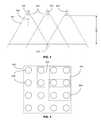
- FIG. 2is a side elevation view of a plurality of luminaires of a lighting system according to an embodiment of the present invention.
- FIG. 3is a side elevation view of a plurality of luminaires of a lighting system according to an embodiment of the present invention.
- FIG. 4is a bottom view of a lighting system according to an embodiment of the present invention.
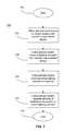
- FIG. 5is a flowchart illustrating a method of operating a lighting system according to an embodiment of the present invention.
- FIG. 6is a flowchart illustrating a method of operating a lighting system according to an alternative embodiment of the present invention.
- FIG. 7is a flowchart illustrating a method of operating a lighting system according to an alternative embodiment of the present invention.
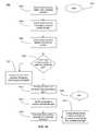
- FIG. 8is a flowchart illustrating a method of operating a lighting system according to an alternative embodiment of the present invention.
- FIG. 9is a flowchart illustrating a method of operating a lighting system according to an alternative embodiment of the present invention.
- FIG. 10is a flowchart illustrating a method of operating a lighting system according to an alternative embodiment of the present invention.
- FIG. 11is a flowchart illustrating a method of operating a lighting system according to an alternative embodiment of the present invention.
- An embodiment of the inventionprovides a lighting system for providing non-homogenous light. More specifically, a lighting system comprising a plurality of luminaires that that emit a plurality of source lights that combine to form a combined light at a distance from the plurality of luminaires is provided.
- the lighting system 100may comprise a computerized device 200 and a plurality of luminaires 300 .
- the computerized device 200may be positioned in communication with each of the plurality of luminaires 300 . Additionally, the computerized device 200 may be configured so as to individually operate each of the plurality of luminaires 300 .
- the operation of the plurality of luminaires 300 by the computerized device 200may cause some or all of the plurality of luminaires 300 to emit a source light.
- the source light emitted by each of the plurality of luminairesmay propagate into a volume adjacent the plurality of luminaires 300 and combine to form a combined light.
- the plurality of luminaires 300may be positioned in such a configuration so as to form an array of luminaires 302 , as shown in FIG. 1 .
- the array 302will be in a row-and-column configuration, such as an N by M array
- the computerized device 200may be any electronic device that contains the necessary electronic components and attending circuitry to enable operation of the plurality of luminaires 300 .
- the computerized device 200may include a microcontroller, such as an integrated circuit.
- the computerized device 200may include communication circuitry that enables the computerized device 200 to be positioned in communication with the plurality of luminaires 300 .
- the communication between the computerized device 200 and the plurality of luminaires 300may be accomplished by any electronic communication means or methods known in the art, including, but not limited to, Ethernet, Universal Serial Bus (USB), IEEE 1394/Firewire, ThunderBolt, 802.XX communication standards including WiFi, Bluetooth, ZigBee, RuBee, and all other wired and wireless communication standard known in the art. More details regarding communication between the computerized device 200 and the plurality of luminaires 300 may be found in U.S. patent application Ser. No. 13/403,531 titled Configurable Environmental Condition Sensing Luminaire, System and Associated Methods which is hereby incorporated by reference in its entirety.
- the computerized device 200may include the necessary electronic components necessary to perform calculations to determine the characteristics of source light emitted by each of the plurality of luminaires 300 as well as the characteristics of a combined light comprising the source lights of all the plurality of luminaires 300 or, alternatively, a combined light comprising the source lights of a subset of the plurality of luminaires 300 .
- the computerized device 200may include electronic components that enable the communication device to communicate with another computerized device so as to receive a lighting scenario.
- a lighting scenariomay be a picture, video, or other visual element that may be recreated, either in whole or in part, by the operation of the plurality of luminaires 300 by the computerized device 200 .
- the receipt of a lighting scenario by the computerized device 200may cause the computerized device 200 to operate the plurality of luminaires 300 responsive to the received lighting scenario.
- the computerized device 200may communicate with the other computerized device so as to receive the lighting scenario by any means or method known in the art, including, but not limited to, the electronic communication means listed hereinabove.
- the computerized device 200may operate the plurality of luminaires 300 in a manner that varies with time responsive to the lighting scenario.
- the lighting scenariomay be a representation of an event.
- the lighting scenariomay be a representation of a naturally occurring phenomenon, such as, for example, the Aurora Borealis.
- the lighting scenariomay be a representation of a human event, such as Mardi Gras.
- the lighting scenariois a visual representation of an event that has associated with it a varying visual element, usually including variations in color, brightness, and any other visual elements.
- These varying visual elementsmay be represented by the plurality of luminaires 300 through their operation by the computerized device 200 . Accordingly, a person looking directly at the plurality of luminaires 300 , such as when they are positioned in an array, may have the impression that they perceive the event that the lighting scenario represents.
- the observerwhen not looking directly at the plurality of luminaires 300 , but instead looking at the walls, floor, or any other object disposed within a volume within which the observer is positioned and into which the plurality of luminaires 300 are emitting light, the observer will not perceive the varying colors, brightness, or other characteristics of light that are varying in the light emitted by the plurality of luminaires 300 individually, as each of the individual emitted lights will have combined to form a light having generally consistent lighting characteristics, such as those that are generally associated with providing normal lighting to a room. More details regarding the combined light are provided hereinbelow.
- the event that is being reproduced by the lighting scenariomay be digitized in a number of ways.
- a video capture device having a field of viewmay be positioned and operated so as to capture a video of the event.
- the video capture devicemay provide a video signal to the computerized device 200 in real-time such that the computerized device can recreate the event as it is happening.
- Such a configurationis typically accomplished by positioning in electrical communication each of the video capture device and the computerized device with a network, either directly or through connection to an intermediate electronic device.
- the video signalmay then be sent from the video capture device to the computerized device 200 across the network.
- a remote computerized deviceis used to facilitate communication between the video capture device and the computerized device 200 .
- an audio capture devicemay be positioned to receive audio input, either electronically or using a microphone, and transmit a signal to the computerized device that may present a visualization of the received audio input.
- the computerized device 200may be associated with a memory within which a lighting scenario may be stored.
- the memorymay be an integral part of the computerized device 200 , or it may be temporarily attached to and associated with the computerized device 200 .
- the lighting scenariomay be stored in the memory for retrieval at another time by the computerized device 200 .
- the computerized device 200may determine the location of each of the plurality of luminaires 300 . More specifically, the computerized device 200 may determine the location of each luminaire 300 with respect to its adjacent luminaires 300 , or it may determine the location of each luminaire 300 with respect to every other luminaire 300 of the plurality of luminaires 300 . In order to determine the location of the plurality of luminaires 300 , the computerized device 200 may enter an acquisition phase, wherein it transmits a signal to each of the plurality of luminaires 300 . In some embodiments, the quantity and arrangement of the plurality of luminaires 300 may be predetermined, and a user may position the luminaires 300 accordingly. The signal sent by the computerized device 200 may either confirm the proper quantity and arrangement of the luminaires 300 or it may indicate a missing or an incorrectly arranged luminaire 300 .
- the luminaires 300may operate a locating device comprised within either some or all of the luminaires 300 to determine their location.
- the locating devicemay function to determine the position of at least the containing luminaire 300 and potentially luminaires 300 adjacent thereto.
- the locating devicemay use any means or method in determining the above locations, including, without limitation, electromagnetic mapping, acoustic mapping, network trace mapping, visible light communication, radio communication, and any other method known in the art. These methods are exemplary only and do not limit the scope of the invention.
- the locating devicemay determine the location of the containing luminaire 300 either with respect to adjacent luminaires, with respect to the entire plurality of luminaires 300 , with respect to the volume into which light emitted by the luminaire 300 will propagate, and any combination thereof. Moreover, the locating device may be configured to detect the presence of interfering objects within the volume or among the plurality of luminaires 300 that may affect the operation of the lighting system.
- the locating devicemay transmit a response signal to the computerized device 200 providing location information for the containing luminaire 300 , adjacent luminaires 300 , the volume into which light emitted by the luminaire 300 will propagate, and any combination thereof.
- the computerized device 200may be programmed to determine how to operate the plurality of luminaires 300 to both represent the selected lighting scenario as well as to result in the selected combined light.
- Each of the plurality of luminaires 300may be configured to produce polychromatic light.
- Polychromatic lightis light that comprises two or more wavelengths, hence being composed of two or more colors. More details regarding luminaires configured to produce polychromatic light, as well as the methods of producing polychromatic light generally, may be found in U.S. patent application Ser. No. 13/107,928 and U.S. Provisional Patent Application Ser. No. 61/643,308, both of which are incorporated by reference hereinabove.
- Some of the luminairesmay be capable of generating a wider variety of lights, including having a broader color gamut, having greater or lesser color intensity, and the like.
- the computerized device 200may selectively operate each of the plurality of luminaires 300 .
- a luminaire 300When a luminaire 300 is operated, it may emit a source light 304 .
- the source light 304 of each luminaire 300may have a known rate of lateral propagation 306 .
- the rate of lateral propagation 306may be described as the rate at which the source light 304 expands through a volume away from a longitudinal axis 308 of the source light 304 .
- Each of the plurality of luminaires 300may have an equivalent rate of lateral propagation 306 , or some or all luminaires 300 may have a rate of lateral propagation 306 that is different from the other luminaires 300 .
- each pair of adjacent luminaires 300may be separated by an offset distance 310 .
- the proportion of the offset distance 310 to the rate of lateral propagation 306 of adjacent luminaires 300may determine a combination distance 312 .
- the combination distance 312may be defined as a distance along the longitudinal axis 308 of a luminaire 300 where the source light 304 of a first luminaire 300 overlaps with the source light 304 of a second luminaire 300 .
- the first and second luminaires 300are adjacent to one another.
- the overlap between the source lights 304 of two or more luminaires 300may be defined as a combined light 314 .
- the offset distance 310 , rate of lateral propagation 306 , or bothmay be configured so as to result in a combination distance 312 that is generally less than the distance to the eye level of an average observer.
- the offset distance 310 between each adjacent luminairesmay be uniform, or it may vary.
- the longitudinal axes 308 defined by each luminaire 300may be parallel, intersecting, or skew.
- some or all of the luminaires 300may be capable of altering their offset distance 310 or angle of their longitudinal axis 308 by repositioning or rotating itself by any electrical, mechanical, magnet, or any other mechanism or system capable of enabling such movement. Moreover, such movement may be controlled by the computerized device 200 and the computerized device 200 may alter the source lights 304 of any moving luminaire 300 to compensate for such movement.
- each luminaire of the plurality of luminaires 300may be operable to emit light having an increased spectral opponency. It is understood in the art that certain wavelengths of light are associated with melatonin suppression in observers of light. More information regarding melatonin suppression may be found in U.S. patent application Ser. No. 13/652,207, which is incorporated by reference hereinabove in its entirety. Moreover, increasing spectral opponency, specifically opponency of generally blue light, is known to reduce melatonin suppression.
- the computerized device 200may be programmed to operate at least one of the plurality of luminaires 300 to emit light having a spectral power distribution that increases spectral opponency, thereby minimizing melatonin suppression. More specifically, the computerized device 200 may be programmed to operate the plurality of luminaires 300 to emit light having a spectral power distribution that reduces the intensity of light having a wavelength associated with melatonin suppression from a maximum intensity associated with that wavelength.
- the computerized device 200may operate at least one of the plurality of luminaires 300 to emit light having an intensity of not greater than about 45% of the maximum intensity at a wavelength of about 440 nm, an intensity of not greater than about 53% of the maximum intensity at a wavelength of about 460 nm, an intensity of not greater than about 75% of the maximum intensity at a wavelength of about 480 nm, an intensity of not greater than about 77% of the maximum intensity at a wavelength of about 560 nm, an intensity of not greater than about 74% of the maximum intensity at a wavelength of about 580 nm, and an intensity of not greater than about 71% of the maximum intensity at a wavelength of about 600 nm.
- the computerized device 200may reduce the intensity of light at the above wavelengths through the use of any method known in the art, including, but not limited to, pulse-width modulation.
- the plurality of luminaires 300may be configured to generate light through the use of light-emitting semiconductors, such as light-emitting diodes (LEDs). Where LEDs are employed, each luminaire of the plurality of luminaires 300 may further include a driver circuit configured to enable the operation of the LEDs by the computerized device 200 . In some embodiments, the driver circuit may be configured to operate the LEDs with a ripple current at frequencies greater than 200 Hz. A ripple current at frequencies above 200 Hz is chosen to avoid biological effects that may be caused by ripple currents at frequencies below 200 Hz. For example, studies have shown that some individuals are sensitive to light flicker below 200 Hz, and in some instances experience headaches, seizures, etc.
- LEDslight-emitting diodes
- the computerized device 200may be in communication with a time-keeping device.
- the time-keeping devicemay be an atomic clock.
- the time-keeping devicemay generate an indication of the current time that is receivable by the computerized device 200 .
- the computerized device 200may operate the plurality of luminaires 300 responsive to the time indicated. For example, if the time indicated is generally associated with evening or night, the computerized device 200 may operate the plurality of luminaires 300 to emit light that generally does not suppress melatonin, therefore avoiding interfering with melatonin levels in observers.
- the computerized device 200may operate the plurality of luminaires to include light having decreased spectral opponency and to include light comprising wavelengths associated with melatonin suppression.
- the combined light 314may be a polychromatic light comprising the wavelengths of each of the source lights 304 that overlapped to form the combined light 314 .
- the source lights 304 emitted by each of the plurality of luminaires 300are monochromatic and have the same single wavelength, the resulting combined light 314 will be similarly monochromatic.
- the polychromaticity of the combined light 314will comprise an increased number of included wavelengths. As the wavelength of each source light 304 varies with time, so too will the wavelengths comprised by the combined light 314 vary with time.
- the combined light 314may have a spectral power distribution configured to increase spectral opponency to thereby reduce melatonin suppression. More specifically, the computerized device 200 may operate at least one of the plurality of luminaires 300 to emit light that, when combined to form the combined light 314 , causes the spectral power distribution of the combined light 314 to have an intensity at wavelengths associated with melatonin suppression that is less than a maximum intensity.
- the computerized device 200may operate the plurality of luminaires 300 such that the combined light 314 has an intensity of not greater than about 45% of the maximum intensity at a wavelength of about 440 nm, an intensity of not greater than about 53% of the maximum intensity at a wavelength of about 460 nm, an intensity of not greater than about 75% of the maximum intensity at a wavelength of about 480 nm, an intensity of not greater than about 77% of the maximum intensity at a wavelength of about 560 nm, an intensity of not greater than about 74% of the maximum intensity at a wavelength of about 580 nm, and an intensity of not greater than about 71% of the maximum intensity at a wavelength of about 600 nm.
- the combined light 314may have other selected lighting characteristics, such as chromaticity, luminous intensity, color rendering index (CRI), color temperature, and any other lighting characteristic.
- the combined light 314may be a generally white light, may have luminous intensity within the range from about 100 lumens to about 2,600 lumens, may be a generally white light, may have a CRI of about 50 or greater, or may have a color temperature within the range from about 2,000 Kelvin to about 25,000 Kelvin, or any combination of the above.
- the combined light 314may form a metamer, wherein the apparent color of the light is the result of the spectral power distribution of the combined source lights 304 combining to form the combined light 314 .
- These selections of lighting characteristicsare exemplary only and non-limiting and any other possible selection for each of the characteristics of light are contemplated and included within the scope of the invention.
- the computerized device 200may control the operation of each of the plurality of luminaires 300 . Furthermore, the computerized device 200 may be configured to operate each of the plurality of luminaires 300 to emit a source light 304 comprising one or more selected wavelengths.
- the source light emitted by each luminaire 300may include a dominant wavelength.
- the dominant wavelengthmay be within a range of wavelengths generally considered as within the visible spectrum of wavelengths. More specifically, the dominant wavelength may be within the range of from about 390 nanometers to about 750 nanometers.
- the dominant wavelengthmay principally define a color of the source light 304 .
- the dominant wavelengthmay be a white color or a non-white color.
- the color of the source light 304 of a luminaire 300may be assigned to the luminaire 300 by the computerized device 200 , which may operate the plurality of luminaires 300 according to a lighting scenario as described hereinabove. More specifically, the computerized device 200 may determine that a luminaire 300 will represent a portion of the lighting scenario, and operate that luminaire 300 so as to represent that portion of the lighting scenario, recreating the lighting characteristics of that portion of the lighting scenario, including such lighting characteristics such as luminous intensity, chromaticity, and any other characteristic which can be controlled by the operation of the luminaire 300 .
- the source light 304 emitted by each luminaire 300may vary with time. More specifically, the computerized device 200 may operate a luminaire 300 to emit a first source light 304 having a first selected characteristic of light. After some interval of time, the computerized device 200 may operate the luminaire 300 to emit a second source light 304 having a second selected characteristic of light that differs from the first selected characteristic of light. Accordingly, the computerized device 200 may operate each of the plurality of luminaires 300 so as to vary the characteristics of the source lights 304 emitted thereby.
- the computerized device 200may be configured to operate the plurality of luminaires 300 so as to emit source lights 304 that combine to form a second combined light 316 at a second combination distance 318 having desired lighting characteristics.
- the second combination distance 318may be defined as a distance along the longitudinal axis 308 of a luminaire 300 where the source light 304 of a first luminaire 300 ′ overlaps with the source light 304 of a second luminaire 300 ′′ and a third luminaire 300 ′′.
- the second combined light 316may essentially contain within it the combined lights of each of the first luminaire 300 ′ and the second luminaire 300 ′′ as well as the second luminaire 300 ′′ and the third luminaire 300 ′′′.
- the second combination distance 318will be greater than a combination distance for the combined lights of the first luminaire 300 ′ and the second luminaire 300 ′′ as well as the second luminaire 300 ′′ and the third luminaire 300 ′′′.
- the combined lights 314 , 316will comprise one or more wavelengths that are determined by the source lights 304 emitted by each of the luminaires 300 that combine to form the combined lights 314 , 316 .
- the plurality of luminaires 300comprises more than two luminaires in the case of combined light 314 , and more than three luminaires 300 in the case of combined light 316 , there will be more than one combined light formed in each of those embodiments.
- the source lights 304 of a luminaire 300comprises one or more wavelengths that differs from the source lights 304 of other luminaires 300 , it is possible for there to be a variety of combined lights comprising different wavelengths in the polychromatic light. Accordingly, where the plurality of luminaires 300 are formed into an array, the combined light formed by the plurality of luminaires 300 may vary across the length and width of an area of illumination offset from the array at the combining distance, depending on what source lights 304 are combining to form the combined light at a given location.
- the computerized device 200may control the operation to control the variation of the combined light formed by the plurality of luminaires 300 across the length and width of the area of illumination. More specifically, the computerized device 200 may control the operation of the plurality of luminaires 300 to control the variation of a characteristic of light, such as those disclosed hereinabove, of the combined light formed thereby. More specifically, the computerized device 200 may control the variation of the characteristic of light to not exceed 5% of a selected value or magnitude.
- the lighting systemmay further comprise one or more optical sensors.
- the optical sensorsmay be positioned so as to measure the source lights, the combined lights, and reflections thereof throughout the volume through which they propagate.
- the optical sensorsmay be placed in electrical communication with the computerized device so as to function as a feedback system, providing information to the computerized device about the volume into which the light emitted by the luminaires is emitted, and if the desired combined light is being formed. Types of information included may be obstructions in the volume, the color of any walls or objects in the volume, the actual combined light, and the like.
- the computerized devicemay alter the source lights of the plurality of luminaires responsive to the indication of the characteristics of light being observed by the optical sensors.
- the computerized device 200may group subsets of the plurality of luminaires 300 into combination groups. Referring now to FIG. 4 , an array 400 of luminaires 300 is depicted, wherein the luminaires 300 are positioned such that the array 400 is in a 4 ⁇ 4 grid configuration.
- the computerized device 200may determine a plurality of combination groups from the array 400 of luminaires 300 . For instance, the computerized device 200 may designate a first combination group 402 comprising a four luminaires 300 in a 2 ⁇ 2 grid configuration. The computerized device 200 may operate each of the luminaires 300 of the first combination group such that a combined light formed by the first combination group 402 is a metamer comprising the wavelengths of light of each source light emitted by the luminaires 300 . Moreover, the computerized device 200 may operate the luminaires 300 of the first combination group 402 such that the metamer formed thereby has one or more selected characteristic of light, such as those described hereinabove.
- the metamermay be configured to have a spectral power distribution that increases spectral opponency, thereby reducing melatonin suppression. More specifically, the computerized device 200 may operate at least one of the plurality of luminaires 300 to emit light that, when combined to form the metamer, causes the spectral power distribution of the metamer to have an intensity at wavelengths associated with melatonin suppression that is less than a maximum intensity.
- the computerized device 200may operate the plurality of luminaires 300 such that the metamer has an intensity of not greater than about 45% of the maximum intensity at a wavelength of about 440 nm, an intensity of not greater than about 53% of the maximum intensity at a wavelength of about 460 nm, an intensity of not greater than about 75% of the maximum intensity at a wavelength of about 480 nm, an intensity of not greater than about 77% of the maximum intensity at a wavelength of about 560 nm, an intensity of not greater than about 74% of the maximum intensity at a wavelength of about 580 nm, and an intensity of not greater than about 71% of the maximum intensity at a wavelength of about 600 nm.
- the computerized devicemay further designate a second combination group 404 .
- the second combination group 404may comprise two luminaires 300 positioned in a 1 ⁇ 2 array.
- the computerized device 200may similarly operate the luminaires 300 of the second combination group 404 such that the metamer formed thereby has one or more selected characteristic of light.
- the characteristic of light selected for the metamer formed by the second combination group 404may be the same as the selected characteristic of light for the metamer formed by the first combination group 402 , or it may be different.
- the selected characteristicsmay be of the same type (i.e., chromaticity, luminous intensity, etc.), the magnitudes may be different.
- the combination height of the metamer formed therebywill be different from the combination height of the metamer formed by the first combination group 402 .
- the computerized device 200may define a third combination group 406 .
- the third combination group 406may comprise four luminaires 300 positioned in a 2 ⁇ 2 array. Moreover, two of the luminaires 300 comprised by the third combination group 406 may also be included in the first combination group 402 . Accordingly, the source lights emitted by luminaires 300 shared between the first combination group 402 and the third combination group 406 will be constituent components of the metamers formed by each of the combination groups. Moreover, any changes to those shared luminaires 300 will affect both metamers formed by the first and third combination groups 402 , 406 . This phenomenon will be discussed in greater detail hereinbelow.
- the method according to the present inventionis directed to a method of operating a lighting system to reproduce a lighting scenario while forming a combined light having selected characteristics of light.
- the lighting systemmay include some or all of the features described hereinabove.
- a computerized devicemay send a first signal to a plurality of luminaires at Step 502 .
- the first signalmay be configured to cause the plurality of luminaires to emit light having a spectral power distribution configured to increase spectral opponency, thereby reducing melatonin suppression, as described hereinabove.
- the luminairesmay operate responsive to the first signal, emitting a source light having a first dominant wavelength.
- the source light emitted by a first luminairemay have a different first dominant wavelength than a dominant wavelength of a source light for a second luminaire.
- the source lights emitted by the luminairesmay combine to form a first combined light.
- the computerized devicemay transmit a second signal to the luminaires. The sequential nature of the above steps results in the second signal being transmitted at some time after the transmittal of the first signal.
- the luminairesmay operate responsive to the second signal, emitting a source light having a second dominant wavelength. For at least one of the luminaires, the first dominant wavelength may be different than the second dominant wavelength.
- the source lights emitted by the luminaires having second dominant wavelengthsmay combine to form a second combined light. The method is ended at Step 514 .
- a method aspect of the present inventionis now described in greater detail.
- the method according to the present inventionis directed to a lighting system that operates responsive to a lighting scenario received from a remote computerized device.
- a computerized device of the lighting systemmay be placed in communication with a remote computerized device, as described hereinabove, at Step 602 .
- the computerized devicemay receive from the remote computerized device a lighting scenario.
- the lighting scenariomay be generated by a signal capture device, such as a video capture device, an audio capture device, a video playback device, an audio playback device, and the like. Furthermore, the lighting scenario may be captured live by the signal capture device. Alternatively, the lighting scenario may be pre-programmed on the remote computerized device.
- the computerized devicemay then operate a plurality of luminaires of the lighting system responsive to the received lighting scenario. For example, the computerized device may operate the luminaires as described in flowchart 500 as shown in FIG. 5 . Any method of operation described in this application or known in the art are contemplated and included within the scope of the invention. The method is ended at Step 608 .
- a method aspect of the present inventionis directed to a lighting system that includes a computerized device comprising a memory.
- a computerized device of the lighting systemmay be placed in communication with a remote computerized device, as described hereinabove, at Step 702 .
- the computerized devicemay receive from the remote computerized device a lighting scenario, also as described hereinabove.
- the computerized devicemay write the received lighting scenario to a memory associated with the computerized device.
- the computerized devicemay retrieve the lighting scenario from the memory and operate the luminaires responsive to the stored lighting scenario, as described hereinabove.
- the methodis ended at Step 710 .
- a method aspect of the present inventionis now described in greater detail.
- the method according to the present inventionis directed to a lighting system that determines the location of a plurality of luminaires positioned in an array.
- a computerized devicemay transmit a locating signal to each of a plurality of luminaires at Step 802 .
- each of the plurality of luminairesmay determine its location by any method disclosed hereinabove.
- Each luminairemay determine its location according to one of at least three location perspectives.
- the containing luminairesmay determine its location with respect to at least one of its adjacent luminaires, as shown in Step 806 , with respect to at least all the other luminaires of the plurality of luminaires, as shown in Step 808 , or with respect to the volume into which light emitted by the plurality of luminaires will propagate into, as sown at Step 810 , and any combination thereof.
- each luminairemay transmit a response signal to the computerized device providing its location information.
- the computerized devicemay operate the luminaires responsive to the response signals received from the luminaires. The location indicated by each response signal associated with each luminaire may facilitate the computerized device in determining which portion of the lighting scenario each luminaire may be assigned and operated to recreate. The method is ended at Step 816 .
- a method aspect of the present inventionis now described in greater detail.
- the method according to the present inventionis directed to a lighting system determines whether light emitted responsive to a lighting scenario will produce a selected combined light.
- a computerized devicemay determine a lighting scenario at Step 902 .
- the determination of the lighting scenariomay include the receipt of a lighting scenario as described hereinabove, or it may include the selection of one lighting scenario from many lighting scenarios available to the computerized device by any of the methods disclosed hereinabove.
- the lighting scenario of this embodimentmay comprise a plurality of pixels arranged into an array.
- the determination of the lighting scenariomay include assigning each pixel of the lighting scenario to a luminaire of the plurality of luminaires, defining a pixel light for each of the luminaires.
- the color of each pixel lightmay be designated a dominant wavelength of a source light for the luminaire associated with the pixel light.
- the lighting scenariomay comprise a plurality of pixels that is greater in number than the number of luminaires in the plurality of luminaires.
- the lighting scenariomay have an aspect ratio that is different than an aspect ratio of the array of luminaires. Accordingly, in determining the lighting scenario, the computerized device may render the lighting scenario either by pixelating, deresolving, cropping, resizing, or in some other way modifying the lighting scenario such that it may be producible by the plurality of luminaires.
- the computerized devicemay determine a selected combined light.
- the selected combined lightmay be a combined light that has a selected characteristic of light as described hereinabove.
- the computerized devicemay determine the selected combined light by a number of methods. One such method is for the computerized device to be pre-programmed to include a predetermined combined light. Another method is for the computerized device to receive included with the lighting scenario a selected combined light. Another method is for the computerized device to receive an input providing the selected combined light.
- the inputmay be received from a variety of sources, including, without limitation, a remote computerized device, such as a computer terminal, a smart phone, a tablet computer, a wireless device specifically associated with the computerized device, or any other electrical device capable of transmitting the selected combined light to the computerized device.
- a remote computerized devicesuch as a computer terminal, a smart phone, a tablet computer, a wireless device specifically associated with the computerized device, or any other electrical device capable of transmitting the selected combined light to the computerized device.
- a remote computerized devicesuch as a computer terminal, a smart phone, a tablet computer, a wireless device specifically associated with the computerized device, or any other electrical device capable of transmitting the selected combined light to the computerized device.
- the selected combined lightmay be configured to have a spectral power distribution configured to increase spectral opponency, thereby reducing melatonin suppression, as described hereinabove.
- the computerized devicemay determine whether a metamer comprising the dominant wavelengths of the plurality of luminaires produces the selected combined light. If, at Step 906 , it is determined the metamer comprising the dominant wavelengths of the plurality of luminaires will produce the selected combined light, then at Step 908 the computerized device may operate the plurality of luminaires according to each of their previously determined pixel lights.
- the computerized devicemay determine a first subordinate light that, when combined with the metamer, will produce the selected combined light.
- the computerized devicemay identify a pixel light, and hence a luminaire, that can be adjusted to include the first subordinate light.
- the computerized devicemay determine a modified pixel light that includes both the dominant wavelength for that pixel light as well as the first subordinate light.
- the computerized devicemay determine that, upon addition of the first subordinate light, the identified pixel light will still produce the color, luminous intensity, or other characteristic of light that is required for conformity with the lighting scenario.
- the computerized devicemay then operate the luminaires according to their pixel light or, in the case of the identified pixel light, the modified pixel light. The method is ended at Step 918 .
- the computerized devicemay determine a lighting scenario, as described hereinabove, at Step 1002 .
- the computerized devicemay determine the selected combined light as described hereinabove.
- the computerized devicemay define a plurality of combination groups consisting of subsets of the plurality of luminaires. The various configurations of combination groups are disclosed hereinabove. Each combination group defined by the computerized device has associated with it a metamer comprising the dominant wavelengths of each of the pixel lights of the combination groups.
- the computerized devicemay determine whether the metamers of each combination group produces the selected combined light. If, at Step 1008 , it is determined the metamer comprising the dominant wavelengths of the plurality of luminaires will produce the selected combined light, then at Step 1010 the computerized device may operate the plurality of luminaires according to each of their previously determined pixel lights.
- the computerized devicemay identify the non-conforming metamer and determine a first subordinate light that, when combined with the metamer, will produce the selected combined light.
- the computerized devicemay identify a first pixel light selected from the pixel lights of the non-conforming combination group that can be adjusted to include the first subordinate light.
- the computerized devicemay determine a first modified pixel light that includes both the dominant wavelength for the identified pixel light as well as the first subordinate light. The computerized device may determine that, upon addition of the first subordinate light, the identified pixel light will still produce the color, luminous intensity, or other characteristic of light that is required for conformity with the lighting scenario. At Step 1018 the computerized device may then operate the luminaires according to their pixel light or, in the case of the identified pixel light, the modified pixel light.
- Step 1012 , 1014 , and 1016may be repeated for each combination group producing a non-conforming metamer. The method is ended at Step 1020 .
- the method according to the present inventionis directed to a lighting system similar to that described in flowchart 1000 of FIG. 10 wherein the computerized device determines a plurality of metamers, further wherein the computerized device defines a plurality of combination groups that are overlapping, such that one luminaire may be included in two or more combination groups.
- the computerized devicemay determine a lighting scenario, as described hereinabove, at Step 1102 .
- the computerized devicemay determine the selected combined light as described hereinabove.
- the computerized devicemay define a plurality of combination groups consisting of subsets of the plurality of luminaires as described hereinabove.
- the computerized devicemay determine whether the metamers of each combination group produces the selected combined light. If, at Step 1108 , it is determined the metamer comprising the dominant wavelengths of the plurality of luminaires will produce the selected combined light, then at Step 1110 the computerized device may operate the plurality of luminaires according to each of their previously determined pixel lights.
- the computerized devicemay identify the non-conforming metamer and determine a first subordinate light that, when combined with the metamer, will produce the selected combined light.
- the computerized devicemay identify a first pixel light selected from the pixel lights of the non-conforming combination group that can be adjusted to include the first subordinate light.
- the computerized devicemay determine a first modified pixel light that includes both the dominant wavelength for the identified pixel light as well as the first subordinate light.
- the computerized devicemay determine that, upon addition of the first subordinate light, the identified pixel light will still produce the color, luminous intensity, or other characteristic of light that is required for conformity with the lighting scenario.
- the combination groups of this embodimentmay overlap such that one luminaire may be included in two or more combination groups. Accordingly, when a modified pixel light is determined, it is possible that the modified pixel light may be associated with a luminaire that is included in more than one combination group, namely a first and second combination groups, wherein at least the first combination group is determined to be producing a non-conforming metamer. Moreover, should that luminaire be included in more than one combination group, it is possible that while the modified pixel light may cause the previously non-conforming metamer of the first combination group to produce the selected combined light, it may have the unintended consequence of causing the metamer of the second combination group to become non-conforming.
- the computerized devicemay determine whether the modified pixel light is included in more than one combination group. If it is determined that the modified pixel light is not associated with more than one combination group, then at Step 1120 the computerized device may then operate the luminaires according to their pixel light or, in the case of the identified pixel light, the modified pixel light.
- the computerized devicemay determine whether a second metamer associated with a second combination group now including the modified pixel light produces the selected combined light. If the second metamer produces the selected combined light, then the method may proceed to Step 1120 and the computerized device may operate the luminaires according to their pixel light or, in the case of the identified pixel light, the modified pixel light.
- the computerized devicemay determine a second subordinate light that, when combined with the second metamer, produces the selected combined light.
- the computerized devicemay then identify a second pixel light from the pixel lights included in the second combination group to include the second subordinate light.
- the second identified pixel lightmay be the same as the first identified pixel light, or it may be a pixel light of the second combination group other than the first identified pixel light.
- the computerized devicemay determine a second modified pixel light that includes both the dominant wavelength for the second identified pixel light as well as the second subordinate light.
- the computerized devicemay determine that, upon addition of the second subordinate light, the second identified pixel light will still produce the color, luminous intensity, or other characteristic of light that is required for conformity with the lighting scenario.
- Step 1118may be performed for the second modified pixel light, with Steps 1120 through 1126 potentially being performed again. It is contemplated that these steps may be performed iteratively until it is determined by the computerized device that the metamer of every combination group produces the selected combined light. Accordingly, the computerized device may operate the luminaires according to their respective pixel light, first modified pixel light, second modified pixel light, and any number modified pixel light as is required. The method is ended at Step 1130 .
Landscapes
- Health & Medical Sciences (AREA)
- Biomedical Technology (AREA)
- Engineering & Computer Science (AREA)
- Psychiatry (AREA)
- Nuclear Medicine, Radiotherapy & Molecular Imaging (AREA)
- Psychology (AREA)
- Social Psychology (AREA)
- Developmental Disabilities (AREA)
- Child & Adolescent Psychology (AREA)
- Pathology (AREA)
- Hospice & Palliative Care (AREA)
- Radiology & Medical Imaging (AREA)
- Life Sciences & Earth Sciences (AREA)
- Animal Behavior & Ethology (AREA)
- General Health & Medical Sciences (AREA)
- Public Health (AREA)
- Veterinary Medicine (AREA)
- Circuit Arrangement For Electric Light Sources In General (AREA)
Abstract
Description
Claims (20)
Priority Applications (13)
| Application Number | Priority Date | Filing Date | Title |
|---|---|---|---|
| US13/803,825US8743023B2 (en) | 2010-07-23 | 2013-03-14 | System for generating non-homogenous biologically-adjusted light and associated methods |
| EP14774608.5AEP2974554A4 (en) | 2013-03-14 | 2014-03-13 | SYSTEM FOR THE PRODUCTION OF NON-HOMOGENEOUS BIOLOGICALLY CONTROLLED LIGHT AND RELATED METHODS |
| PCT/US2014/026141WO2014160244A1 (en) | 2013-03-14 | 2014-03-13 | System for generating non-homogenous biologically-adjusted light and associated methods |
| HK16101059.8AHK1213723A1 (en) | 2013-03-14 | 2014-03-13 | System for generating non-homogenous biologically-adjusted light and associated methods |
| CN201480027170.7ACN105210452A (en) | 2013-03-14 | 2014-03-13 | System for generating non-homogenous biologically-adjusted light and associated methods |
| JP2016502062AJP6367912B2 (en) | 2013-03-14 | 2014-03-13 | System for generating heterogeneous biologically modulated light and related methods |
| US14/260,371US9265968B2 (en) | 2010-07-23 | 2014-04-24 | System for generating non-homogenous biologically-adjusted light and associated methods |
| US14/573,922US9532423B2 (en) | 2010-07-23 | 2014-12-17 | System and methods for operating a lighting device |
| US14/590,557US9827439B2 (en) | 2010-07-23 | 2015-01-06 | System for dynamically adjusting circadian rhythm responsive to scheduled events and associated methods |
| US15/370,802US9794996B2 (en) | 2010-07-23 | 2016-12-06 | System and methods for operating a lighting device |
| US15/483,327US9974973B2 (en) | 2010-07-23 | 2017-04-10 | System and associated methods for dynamically adjusting circadian rhythm responsive to calendared future events |
| US15/935,391US10258808B2 (en) | 2010-07-23 | 2018-03-26 | System and associated methods for dynamically adjusting circadian rhythm responsive to identified future events |
| US16/271,208US10765886B2 (en) | 2010-07-23 | 2019-02-08 | System, user device and associated methods for dynamically adjusting circadian rhythm responsive to future events |
Applications Claiming Priority (9)
| Application Number | Priority Date | Filing Date | Title |
|---|---|---|---|
| US12/842,887US8253336B2 (en) | 2010-07-23 | 2010-07-23 | LED lamp for producing biologically-corrected light |
| US13/107,928US8547391B2 (en) | 2011-05-15 | 2011-05-15 | High efficacy lighting signal converter and associated methods |
| US13/174,339US8324808B2 (en) | 2010-07-23 | 2011-06-30 | LED lamp for producing biologically-corrected light |
| US13/234,371US8465167B2 (en) | 2011-09-16 | 2011-09-16 | Color conversion occlusion and associated methods |
| US201261643308P | 2012-05-06 | 2012-05-06 | |
| US201261643316P | 2012-05-06 | 2012-05-06 | |
| US13/652,207US8643276B2 (en) | 2010-07-23 | 2012-10-15 | LED lamp for producing biologically-corrected light |
| US13/709,942US8760370B2 (en) | 2011-05-15 | 2012-12-10 | System for generating non-homogenous light and associated methods |
| US13/803,825US8743023B2 (en) | 2010-07-23 | 2013-03-14 | System for generating non-homogenous biologically-adjusted light and associated methods |
Related Parent Applications (3)
| Application Number | Title | Priority Date | Filing Date |
|---|---|---|---|
| US13/107,928Continuation-In-PartUS8547391B2 (en) | 2010-07-23 | 2011-05-15 | High efficacy lighting signal converter and associated methods |
| US13/652,207Continuation-In-PartUS8643276B2 (en) | 2010-07-23 | 2012-10-15 | LED lamp for producing biologically-corrected light |
| US13/709,942Continuation-In-PartUS8760370B2 (en) | 2010-07-23 | 2012-12-10 | System for generating non-homogenous light and associated methods |
Related Child Applications (3)
| Application Number | Title | Priority Date | Filing Date |
|---|---|---|---|
| US13/107,928Continuation-In-PartUS8547391B2 (en) | 2010-07-23 | 2011-05-15 | High efficacy lighting signal converter and associated methods |
| US14/260,371ContinuationUS9265968B2 (en) | 2010-07-23 | 2014-04-24 | System for generating non-homogenous biologically-adjusted light and associated methods |
| US14/573,922ContinuationUS9532423B2 (en) | 2010-07-23 | 2014-12-17 | System and methods for operating a lighting device |
Publications (2)
| Publication Number | Publication Date |
|---|---|
| US20130257312A1 US20130257312A1 (en) | 2013-10-03 |
| US8743023B2true US8743023B2 (en) | 2014-06-03 |
Family
ID=49233997
Family Applications (2)
| Application Number | Title | Priority Date | Filing Date |
|---|---|---|---|
| US13/803,825ActiveUS8743023B2 (en) | 2010-07-23 | 2013-03-14 | System for generating non-homogenous biologically-adjusted light and associated methods |
| US14/260,371Expired - Fee RelatedUS9265968B2 (en) | 2010-07-23 | 2014-04-24 | System for generating non-homogenous biologically-adjusted light and associated methods |
Family Applications After (1)
| Application Number | Title | Priority Date | Filing Date |
|---|---|---|---|
| US14/260,371Expired - Fee RelatedUS9265968B2 (en) | 2010-07-23 | 2014-04-24 | System for generating non-homogenous biologically-adjusted light and associated methods |
Country Status (1)
| Country | Link |
|---|---|
| US (2) | US8743023B2 (en) |
Cited By (15)
| Publication number | Priority date | Publication date | Assignee | Title |
|---|---|---|---|---|
| US9265968B2 (en) | 2010-07-23 | 2016-02-23 | Biological Illumination, Llc | System for generating non-homogenous biologically-adjusted light and associated methods |
| US9532423B2 (en) | 2010-07-23 | 2016-12-27 | Lighting Science Group Corporation | System and methods for operating a lighting device |
| US9595118B2 (en) | 2011-05-15 | 2017-03-14 | Lighting Science Group Corporation | System for generating non-homogenous light and associated methods |
| US9768831B2 (en) | 2014-09-02 | 2017-09-19 | LIFI Labs, Inc. | Power outlet and method for use |
| US9788387B2 (en) | 2015-09-15 | 2017-10-10 | Biological Innovation & Optimization Systems, LLC | Systems and methods for controlling the spectral content of LED lighting devices |
| US9827439B2 (en) | 2010-07-23 | 2017-11-28 | Biological Illumination, Llc | System for dynamically adjusting circadian rhythm responsive to scheduled events and associated methods |
| US9844116B2 (en) | 2015-09-15 | 2017-12-12 | Biological Innovation & Optimization Systems, LLC | Systems and methods for controlling the spectral content of LED lighting devices |
| US9883563B2 (en) | 2014-05-22 | 2018-01-30 | LIFI Labs, Inc. | Directional lighting system and method |
| US9943042B2 (en) | 2015-05-18 | 2018-04-17 | Biological Innovation & Optimization Systems, LLC | Grow light embodying power delivery and data communications features |
| US10375789B2 (en) | 2014-05-22 | 2019-08-06 | LIFI Labs, Inc. | Directional lighting system and method |
| US10440794B2 (en) | 2016-11-02 | 2019-10-08 | LIFI Labs, Inc. | Lighting system and method |
| US10588206B2 (en) | 2013-11-14 | 2020-03-10 | LIFI Labs, Inc. | Resettable lighting system and method |
| US10595376B2 (en) | 2016-09-13 | 2020-03-17 | Biological Innovation & Optimization Systems, LLC | Systems and methods for controlling the spectral content of LED lighting devices |
| US10851950B2 (en) | 2013-10-15 | 2020-12-01 | LIFI Labs, Inc. | Lighting assembly |
| US12080158B2 (en) | 2014-09-02 | 2024-09-03 | Feit Electric Company, Inc. | Lighting system |
Families Citing this family (10)
| Publication number | Priority date | Publication date | Assignee | Title |
|---|---|---|---|---|
| US8754832B2 (en) | 2011-05-15 | 2014-06-17 | Lighting Science Group Corporation | Lighting system for accenting regions of a layer and associated methods |
| US9173269B2 (en) | 2011-05-15 | 2015-10-27 | Lighting Science Group Corporation | Lighting system for accentuating regions of a layer and associated methods |
| WO2015160564A2 (en)* | 2014-04-15 | 2015-10-22 | 3M Innovative Properties Company | Luminaire for crosswalk, method for making, and method for controlling |
| US9326359B2 (en) | 2014-09-02 | 2016-04-26 | LIFI Labs, Inc. | Lighting system operation management method |
| NZ773836A (en) | 2015-03-16 | 2022-07-01 | Magic Leap Inc | Methods and systems for diagnosing and treating health ailments |
| JP6923552B2 (en) | 2016-04-08 | 2021-08-18 | マジック リープ, インコーポレイテッドMagic Leap,Inc. | Augmented reality systems and methods with varifocal lens elements |
| IL311431A (en) | 2017-02-23 | 2024-05-01 | Magic Leap Inc | Display system with variable power reflector |
| US11058889B1 (en) | 2017-04-03 | 2021-07-13 | Xiant Technologies, Inc. | Method of using photon modulation for regulation of hormones in mammals |
| CN110738957B (en)* | 2019-09-17 | 2023-04-25 | 苏州佳世达电通有限公司 | Display system and color characteristic measurement method |
| TWI716212B (en)* | 2019-12-04 | 2021-01-11 | 美商美國未來科技公司 | Dynamic light field system |
Citations (219)
| Publication number | Priority date | Publication date | Assignee | Title |
|---|---|---|---|---|
| US5046494A (en) | 1990-08-27 | 1991-09-10 | John Searfoss | Phototherapy method |
| US5523878A (en) | 1994-06-30 | 1996-06-04 | Texas Instruments Incorporated | Self-assembled monolayer coating for micro-mechanical devices |
| US5680230A (en) | 1993-09-09 | 1997-10-21 | Canon Kabushiki Kaisha | Image processing method and apparatus thereof |
| US5704701A (en) | 1992-03-05 | 1998-01-06 | Rank Brimar Limited | Spatial light modulator system |
| EP0851260A2 (en) | 1996-12-16 | 1998-07-01 | Ngk Insulators, Ltd. | Display device |
| US5813753A (en) | 1997-05-27 | 1998-09-29 | Philips Electronics North America Corporation | UV/blue led-phosphor device with efficient conversion of UV/blues light to visible light |
| US5997150A (en) | 1995-10-25 | 1999-12-07 | Texas Instruments Incorporated | Multiple emitter illuminator engine |
| US6140646A (en) | 1998-12-17 | 2000-10-31 | Sarnoff Corporation | Direct view infrared MEMS structure |
| US6259572B1 (en) | 1996-02-21 | 2001-07-10 | Rosco Laboratories, Inc. | Photographic color effects lighting filter system |
| US6341876B1 (en) | 1997-02-19 | 2002-01-29 | Digital Projection Limited | Illumination system |
| US6356700B1 (en) | 1998-06-08 | 2002-03-12 | Karlheinz Strobl | Efficient light engine systems, components and methods of manufacture |
| US20020113555A1 (en) | 1997-08-26 | 2002-08-22 | Color Kinetics, Inc. | Lighting entertainment system |
| US6450652B1 (en) | 2001-05-24 | 2002-09-17 | Daniel Nathan Karpen | Neodymium oxide doped motor vehicle windshield and safety glazing material |
| US6459919B1 (en) | 1997-08-26 | 2002-10-01 | Color Kinetics, Incorporated | Precision illumination methods and systems |
| US6528954B1 (en) | 1997-08-26 | 2003-03-04 | Color Kinetics Incorporated | Smart light bulb |
| US6561656B1 (en) | 2001-09-17 | 2003-05-13 | Mitsubishi Denki Kabushiki Kaisha | Illumination optical system with reflecting light valve |
| US6586882B1 (en) | 1999-04-20 | 2003-07-01 | Koninklijke Philips Electronics N.V. | Lighting system |
| US6594090B2 (en) | 2001-08-27 | 2003-07-15 | Eastman Kodak Company | Laser projection display system |
| WO2004011846A1 (en) | 2002-07-25 | 2004-02-05 | Philips Intellectual Property & Standards Gmbh | Lamp system with green-blue gas-discharge lamp and yellow-red led |
| US20040052076A1 (en) | 1997-08-26 | 2004-03-18 | Mueller George G. | Controlled lighting methods and apparatus |
| US6734639B2 (en) | 2001-08-15 | 2004-05-11 | Koninklijke Philips Electronics N.V. | Sample and hold method to achieve square-wave PWM current source for light emitting diode arrays |
| US6733135B2 (en) | 2002-04-02 | 2004-05-11 | Samsung Electronics Co., Ltd. | Image projection apparatus |
| US20040093045A1 (en) | 2002-10-23 | 2004-05-13 | Charles Bolta | Balanced blue spectrum therapy lighting |
| US20040119086A1 (en) | 2002-11-25 | 2004-06-24 | Matsushita Electric Industrial Co. Ltd. | Led Lamp |
| US6762562B2 (en) | 2002-11-19 | 2004-07-13 | Denovo Lighting, Llc | Tubular housing with light emitting diodes |
| US6767111B1 (en) | 2003-02-26 | 2004-07-27 | Kuo-Yen Lai | Projection light source from light emitting diodes |
| US6817735B2 (en) | 2001-05-24 | 2004-11-16 | Matsushita Electric Industrial Co., Ltd. | Illumination light source |
| US6870523B1 (en) | 2000-06-07 | 2005-03-22 | Genoa Color Technologies | Device, system and method for electronic true color display |
| US20050062446A1 (en)* | 2003-07-23 | 2005-03-24 | Tir Systems Ltd. | Control system for an illumination device incorporating discrete light sources |
| US6871982B2 (en) | 2003-01-24 | 2005-03-29 | Digital Optics International Corporation | High-density illumination system |
| US6902296B2 (en) | 2002-06-15 | 2005-06-07 | Searfoss, Iii Robert Lee | Nightlight for phototherapy |
| US20050189557A1 (en) | 2004-02-26 | 2005-09-01 | Joseph Mazzochette | Light emitting diode package assembly that emulates the light pattern produced by an incandescent filament bulb |
| US20050218780A1 (en) | 2002-09-09 | 2005-10-06 | Hsing Chen | Method for manufacturing a triple wavelengths white LED |
| US6967761B2 (en) | 2000-10-31 | 2005-11-22 | Microsoft Corporation | Microelectrical mechanical structure (MEMS) optical modulator and optical display system |
| US20050267213A1 (en) | 2004-01-08 | 2005-12-01 | Dusa Pharmaceuticals, Inc. | Use of photodynamic therapy to enhance treatment with immuno-modulating agents |
| US6974713B2 (en) | 2000-08-11 | 2005-12-13 | Reflectivity, Inc. | Micromirrors with mechanisms for enhancing coupling of the micromirrors with electrostatic fields |
| US20060002108A1 (en) | 2004-06-30 | 2006-01-05 | Ouderkirk Andrew J | Phosphor based illumination system having a short pass reflector and method of making same |
| WO2006001221A1 (en) | 2004-06-29 | 2006-01-05 | Matsushita Electric Industrial Co., Ltd. | Illumination source |
| US20060002110A1 (en) | 2004-03-15 | 2006-01-05 | Color Kinetics Incorporated | Methods and systems for providing lighting systems |
| US7008559B2 (en) | 2001-06-06 | 2006-03-07 | Nomadics, Inc. | Manganese doped upconversion luminescence nanoparticles |
| US7012542B2 (en) | 2002-04-05 | 2006-03-14 | Gibson Guitar Corp. | Multicolor function indicator light |
| US7034934B2 (en) | 2003-12-30 | 2006-04-25 | Neway Systems & Products, Inc. | Anti-carcinogenic lights and lighting |
| US7042623B1 (en) | 2004-10-19 | 2006-05-09 | Reflectivity, Inc | Light blocking layers in MEMS packages |
| US7058197B1 (en) | 1999-11-04 | 2006-06-06 | Board Of Trustees Of The University Of Illinois | Multi-variable model for identifying crop response zones in a field |
| US7072096B2 (en) | 2001-12-14 | 2006-07-04 | Digital Optics International, Corporation | Uniform illumination system |
| US7070281B2 (en) | 2002-12-04 | 2006-07-04 | Nec Viewtechnology, Ltd. | Light source device and projection display |
| US7075707B1 (en) | 1998-11-25 | 2006-07-11 | Research Foundation Of The University Of Central Florida, Incorporated | Substrate design for optimized performance of up-conversion phosphors utilizing proper thermal management |
| US20060164005A1 (en) | 2005-01-25 | 2006-07-27 | Chuan-Sheng Sun | Illumination apparatus having adjustable color temperature and method for adjusting the color temperature |
| US7083304B2 (en) | 2003-08-01 | 2006-08-01 | Illumination Management Solutions, Inc. | Apparatus and method of using light sources of differing wavelengths in an unitized beam |
| US7095053B2 (en) | 2003-05-05 | 2006-08-22 | Lamina Ceramics, Inc. | Light emitting diodes packaged for high temperature operation |
| US7144131B2 (en) | 2004-09-29 | 2006-12-05 | Advanced Optical Technologies, Llc | Optical system using LED coupled with phosphor-doped reflective materials |
| US20060285193A1 (en) | 2005-06-03 | 2006-12-21 | Fuji Photo Film Co., Ltd. | Optical modulation element array |
| US7157745B2 (en) | 2004-04-09 | 2007-01-02 | Blonder Greg E | Illumination devices comprising white light emitting diodes and diode arrays and method and apparatus for making them |
| US20070013871A1 (en) | 2005-07-15 | 2007-01-18 | Marshall Stephen W | Light-emitting diode (LED) illumination in display systems using spatial light modulators (SLM) |
| US7178941B2 (en) | 2003-05-05 | 2007-02-20 | Color Kinetics Incorporated | Lighting methods and systems |
| US20070040512A1 (en)* | 2005-08-17 | 2007-02-22 | Tir Systems Ltd. | Digitally controlled luminaire system |
| US7184201B2 (en) | 2004-11-02 | 2007-02-27 | Texas Instruments Incorporated | Digital micro-mirror device having improved contrast and method for the same |
| US7187484B2 (en) | 2002-12-30 | 2007-03-06 | Texas Instruments Incorporated | Digital micromirror device with simplified drive electronics for use as temporal light modulator |
| EP1671059B1 (en) | 2003-10-03 | 2007-04-04 | General Electric Company | Automotive headlamps with improved beam chromaticity |
| US7213926B2 (en) | 2004-11-12 | 2007-05-08 | Hewlett-Packard Development Company, L.P. | Image projection system and method |
| US7234844B2 (en) | 2002-12-11 | 2007-06-26 | Charles Bolta | Light emitting diode (L.E.D.) lighting fixtures with emergency back-up and scotopic enhancement |
| US20070159492A1 (en) | 2006-01-11 | 2007-07-12 | Wintek Corporation | Image processing method and pixel arrangement used in the same |
| US20070165193A1 (en) | 2006-01-19 | 2007-07-19 | Kabushiki Kaisha Toshiba | Projection type image-displaying system, projection type image-displaying apparatus, and lamp lighting-controlling method |
| US7247874B2 (en) | 2003-05-26 | 2007-07-24 | Agfa-Gevaert Healthcare Gmbh | Device for detecting information contained in a phosphor layer |
| US7246923B2 (en) | 2004-02-11 | 2007-07-24 | 3M Innovative Properties Company | Reshaping light source modules and illumination systems using the same |
| US7252408B2 (en) | 2004-07-19 | 2007-08-07 | Lamina Ceramics, Inc. | LED array package with internal feedback and control |
| US7255469B2 (en) | 2004-06-30 | 2007-08-14 | 3M Innovative Properties Company | Phosphor based illumination system having a light guide and an interference reflector |
| US7261453B2 (en) | 2005-01-25 | 2007-08-28 | Morejon Israel J | LED polarizing optics for color illumination system and method of using same |
| US7289090B2 (en) | 2003-12-10 | 2007-10-30 | Texas Instruments Incorporated | Pulsed LED scan-ring array for boosting display system lumens |
| US20070262714A1 (en) | 2006-05-15 | 2007-11-15 | X-Rite, Incorporated | Illumination source including photoluminescent material and a filter, and an apparatus including same |
| US7300177B2 (en) | 2004-02-11 | 2007-11-27 | 3M Innovative Properties | Illumination system having a plurality of light source modules disposed in an array with a non-radially symmetrical aperture |
| US7303291B2 (en) | 2004-03-31 | 2007-12-04 | Sanyo Electric Co., Ltd. | Illumination apparatus and video projection display system |
| US7319293B2 (en) | 2004-04-30 | 2008-01-15 | Lighting Science Group Corporation | Light bulb having wide angle light dispersion using crystalline material |
| US7324076B2 (en) | 2004-07-28 | 2008-01-29 | Avago Technologies Ecbu Ip (Singapore) Pte. Ltd. | Methods and apparatus for setting the color point of an LED light source |
| US7325956B2 (en) | 2005-01-25 | 2008-02-05 | Jabil Circuit, Inc. | Light-emitting diode (LED) illumination system for a digital micro-mirror device (DMD) and method of providing same |
| US7342658B2 (en) | 2005-12-28 | 2008-03-11 | Eastman Kodak Company | Programmable spectral imaging system |
| US7344279B2 (en) | 2003-12-11 | 2008-03-18 | Philips Solid-State Lighting Solutions, Inc. | Thermal management methods and apparatus for lighting devices |
| US7349095B2 (en) | 2005-05-19 | 2008-03-25 | Casio Computer Co., Ltd. | Light source apparatus and projection apparatus |
| US7353859B2 (en) | 2004-11-24 | 2008-04-08 | General Electric Company | Heat sink with microchannel cooling for power devices |
| US7369056B2 (en) | 2005-11-16 | 2008-05-06 | Hendrix Wire & Cable, Inc. | Photoelectric controller for electric street lighting |
| US20080119912A1 (en) | 2006-01-11 | 2008-05-22 | Stephen Bryce Hayes | Phototherapy lights |
| US7382632B2 (en) | 2005-04-06 | 2008-06-03 | International Business Machines Corporation | Computer acoustic baffle and cable management system |
| US7382091B2 (en) | 2005-07-27 | 2008-06-03 | Lung-Chien Chen | White light emitting diode using phosphor excitation |
| US20080143973A1 (en) | 2006-10-12 | 2008-06-19 | Jing Miau Wu | Light source device of laser LED and projector having the same device |
| US20080198572A1 (en) | 2007-02-21 | 2008-08-21 | Medendorp Nicholas W | LED lighting systems including luminescent layers on remote reflectors |
| US7427146B2 (en) | 2004-02-11 | 2008-09-23 | 3M Innovative Properties Company | Light-collecting illumination system |
| US20080232084A1 (en) | 2007-03-19 | 2008-09-25 | Nec Lighting, Ltd | White light source device |
| JP2008226567A (en) | 2007-03-12 | 2008-09-25 | Yamaguchi Univ | Street light |
| US7429983B2 (en) | 2005-11-01 | 2008-09-30 | Cheetah Omni, Llc | Packet-based digital display system |
| US7436996B2 (en) | 2001-06-07 | 2008-10-14 | Genoa Color Technologies Ltd | Device, system and method of data conversion for wide gamut displays |
| US7434946B2 (en) | 2005-06-17 | 2008-10-14 | Texas Instruments Incorporated | Illumination system with integrated heat dissipation device for use in display systems employing spatial light modulators |
| US7438443B2 (en) | 2003-09-19 | 2008-10-21 | Ricoh Company, Limited | Lighting device, image-reading device, color-document reading apparatus, image-forming apparatus, projection apparatus |
| US7476016B2 (en) | 2005-06-28 | 2009-01-13 | Seiko Instruments Inc. | Illuminating device and display device including the same |
| US7497596B2 (en) | 2001-12-29 | 2009-03-03 | Mane Lou | LED and LED lamp |
| US20090059585A1 (en) | 2007-08-29 | 2009-03-05 | Young Optics Inc. | Illumination system |
| US7521875B2 (en) | 2004-04-23 | 2009-04-21 | Lighting Science Group Corporation | Electronic light generating element light bulb |
| US7520607B2 (en) | 2002-08-28 | 2009-04-21 | Melcort Inc. | Device for the prevention of melationin suppression by light at night |
| US7528421B2 (en) | 2003-05-05 | 2009-05-05 | Lamina Lighting, Inc. | Surface mountable light emitting diode assemblies packaged for high temperature operation |
| US7530708B2 (en) | 2004-10-04 | 2009-05-12 | Lg Electronics Inc. | Surface emitting light source and projection display device using the same |
| US20090128781A1 (en) | 2006-06-13 | 2009-05-21 | Kenneth Li | LED multiplexer and recycler and micro-projector incorporating the Same |
| US7537347B2 (en) | 2005-11-29 | 2009-05-26 | Texas Instruments Incorporated | Method of combining dispersed light sources for projection display |
| US7540616B2 (en) | 2005-12-23 | 2009-06-02 | 3M Innovative Properties Company | Polarized, multicolor LED-based illumination source |
| US7556406B2 (en) | 2003-03-31 | 2009-07-07 | Lumination Llc | Led light with active cooling |
| US7556376B2 (en) | 2006-08-23 | 2009-07-07 | High Performance Optics, Inc. | System and method for selective light inhibition |
| US7573210B2 (en) | 2004-10-12 | 2009-08-11 | Koninklijke Philips Electronics N.V. | Method and system for feedback and control of a luminaire |
| US20090232683A1 (en) | 2006-12-09 | 2009-09-17 | Murata Manufacturing Co., Ltd. | Piezoelectric micro-blower |
| US7598961B2 (en) | 2003-10-21 | 2009-10-06 | Samsung Electronics Co., Ltd. | method and apparatus for converting from a source color space to a target color space |
| US7598686B2 (en) | 1997-12-17 | 2009-10-06 | Philips Solid-State Lighting Solutions, Inc. | Organic light emitting diode methods and apparatus |
| WO2009121539A1 (en) | 2008-03-31 | 2009-10-08 | Tridonicatco Schweiz Ag | System and method for controlling leds |
| US7605971B2 (en) | 2003-11-01 | 2009-10-20 | Silicon Quest Kabushiki-Kaisha | Plurality of hidden hinges for mircromirror device |
| US20090273931A1 (en) | 2007-01-15 | 2009-11-05 | Alps Electric Co., Ltd. | Illumination device and input unit with illumination device |
| US7619372B2 (en) | 2007-03-02 | 2009-11-17 | Lighting Science Group Corporation | Method and apparatus for driving a light emitting diode |
| US20090284169A1 (en)* | 2008-05-16 | 2009-11-19 | Charles Bernard Valois | Systems and Methods for Communicating in a Lighting Network |
| US7626755B2 (en) | 2007-01-31 | 2009-12-01 | Panasonic Corporation | Wavelength converter and two-dimensional image display device |
| US20090303694A1 (en) | 2006-03-31 | 2009-12-10 | Seoul Semiconductor Co., Ltd. | Light emitting device and lighting system having the same |
| US7633093B2 (en) | 2003-05-05 | 2009-12-15 | Lighting Science Group Corporation | Method of making optical light engines with elevated LEDs and resulting product |
| US7633779B2 (en) | 2007-01-31 | 2009-12-15 | Lighting Science Group Corporation | Method and apparatus for operating a light emitting diode with a dimmer |
| US7637643B2 (en) | 2007-11-27 | 2009-12-29 | Lighting Science Group Corporation | Thermal and optical control in a light fixture |
| US20100001652A1 (en) | 2006-09-11 | 2010-01-07 | Jan Willy Damsleth | Control device, system and method for public illumination |
| US20100006762A1 (en) | 2007-03-27 | 2010-01-14 | Kabushiki Kaisha Toshiba | Scintillator panel and radiation detector |
| US20100051976A1 (en) | 2006-11-15 | 2010-03-04 | Lemnis Lighting Patent Holding B.V. | Led lighting assembly |
| US20100053959A1 (en) | 2007-04-16 | 2010-03-04 | Koninklijke Philips Electronics N.V. | Optical arrangement |
| US7679281B2 (en) | 2007-03-19 | 2010-03-16 | Seoul Semiconductor Co., Ltd. | Light emitting device having various color temperature |
| US7678140B2 (en) | 2000-05-10 | 2010-03-16 | George Brainard | Photoreceptor system for melatonin regulation and phototherapy |
| US7677736B2 (en) | 2004-02-27 | 2010-03-16 | Panasonic Corporation | Illumination light source and two-dimensional image display using same |
| US7684007B2 (en) | 2004-08-23 | 2010-03-23 | The Boeing Company | Adaptive and interactive scene illumination |
| US20100076250A1 (en) | 2007-03-09 | 2010-03-25 | Koninklijke Philips Electronics N.V. | Lighting system for energy stimulation |
| US7703943B2 (en) | 2007-05-07 | 2010-04-27 | Intematix Corporation | Color tunable light source |
| US7705810B2 (en) | 2003-05-07 | 2010-04-27 | Samsung Electronics Co., Ltd. | Four-color data processing system |
| US20100103389A1 (en) | 2008-10-28 | 2010-04-29 | Mcvea Kenneth Brian | Multi-MEMS Single Package MEMS Device |
| US7709811B2 (en) | 2007-07-03 | 2010-05-04 | Conner Arlie R | Light emitting diode illumination system |
| US7708452B2 (en) | 2006-06-08 | 2010-05-04 | Lighting Science Group Corporation | Lighting apparatus including flexible power supply |
| CN101702421A (en) | 2009-10-23 | 2010-05-05 | 中外合资江苏稳润光电有限公司 | Manufacturing method of white light LED |
| US20100121420A1 (en) | 2007-04-30 | 2010-05-13 | Peter Depew Fiset | Uva1-led phototherapy device and method |
| US7719766B2 (en) | 2007-06-20 | 2010-05-18 | Texas Instruments Incorporated | Illumination source and method therefor |
| US7728846B2 (en) | 2003-10-21 | 2010-06-01 | Samsung Electronics Co., Ltd. | Method and apparatus for converting from source color space to RGBW target color space |
| US7732825B2 (en) | 2007-03-13 | 2010-06-08 | Seoul Opto Device Co., Ltd. | AC light emitting diode |
| US20100157573A1 (en) | 2008-12-19 | 2010-06-24 | Panasonic Electric Works Co., Ltd. | Light source apparatus |
| US7748845B2 (en) | 2002-08-28 | 2010-07-06 | Robert Casper | Method and device for preventing alterations in circadian rhythm |
| US7766490B2 (en) | 2006-12-13 | 2010-08-03 | Philips Lumileds Lighting Company, Llc | Multi-color primary light generation in a projection system using LEDs |
| US20100202129A1 (en) | 2009-01-21 | 2010-08-12 | Abu-Ageel Nayef M | Illumination system utilizing wavelength conversion materials and light recycling |
| US20100213859A1 (en) | 2006-01-20 | 2010-08-26 | Exclara Inc. | Adaptive Current Regulation for Solid State Lighting |
| US20100231863A1 (en) | 2007-10-08 | 2010-09-16 | Koninklijke Philips Electronics N.V. | Lighting device, array of lighting devices and optical projection device |
| US20100231131A1 (en) | 2009-03-11 | 2010-09-16 | Anderson Deloren E | Light array maintenance system and method |
| US20100244740A1 (en) | 2007-08-24 | 2010-09-30 | Photonic Developments Llc | Multi-chip light emitting diode light device |
| US20100244700A1 (en) | 2007-12-24 | 2010-09-30 | Patrick Chong | System for Representing Colors Including an Integrating Light Capsule |
| US20100244724A1 (en) | 2007-06-05 | 2010-09-30 | Koninklijke Philips Electronics N.V. | Lighting system for horticultural applications |
| US20100244735A1 (en) | 2009-03-26 | 2010-09-30 | Energy Focus, Inc. | Lighting Device Supplying Temporally Appropriate Light |
| US7819556B2 (en) | 2006-12-22 | 2010-10-26 | Nuventix, Inc. | Thermal management system for LED array |
| US20100270942A1 (en) | 2009-04-24 | 2010-10-28 | City University Of Hong Kong | Apparatus and methods of operation of passive led lighting equipment |
| US20100277316A1 (en) | 2008-01-17 | 2010-11-04 | Koninklijke Philips Electronics N.V. | Lighting device |
| US20100277084A1 (en) | 2005-06-28 | 2010-11-04 | Seoul Opto Device Co., Ltd. | Light emitting device for ac power operation |
| US7828453B2 (en) | 2009-03-10 | 2010-11-09 | Nepes Led Corporation | Light emitting device and lamp-cover structure containing luminescent material |
| US7828465B2 (en) | 2007-05-04 | 2010-11-09 | Koninlijke Philips Electronis N.V. | LED-based fixtures and related methods for thermal management |
| US7832878B2 (en) | 2006-03-06 | 2010-11-16 | Innovations In Optics, Inc. | Light emitting diode projection system |
| US7835056B2 (en) | 2005-05-13 | 2010-11-16 | Her Majesty the Queen in Right of Canada, as represented by Institut National d'Optique | Image projector with flexible reflective analog modulator |
| US7834867B2 (en) | 2006-04-11 | 2010-11-16 | Microvision, Inc. | Integrated photonics module and devices using integrated photonics modules |
| US7841714B2 (en) | 2008-02-07 | 2010-11-30 | Quantum Modulation Scientific Inc. | Retinal melatonin suppressor |
| US20100302464A1 (en) | 2009-05-29 | 2010-12-02 | Soraa, Inc. | Laser Based Display Method and System |
| US20100308738A1 (en) | 2009-06-04 | 2010-12-09 | Exclara Inc. | Apparatus, Method and System for Providing AC Line Power to Lighting Devices |
| US20100315320A1 (en) | 2007-12-07 | 2010-12-16 | Sony Corporation | Light source device and display device |
| US7855376B2 (en) | 2005-12-19 | 2010-12-21 | Institut National D'optique | Lighting system and method for illuminating and detecting object |
| US20100320927A1 (en) | 2009-06-22 | 2010-12-23 | Richard Landry Gray | Power Reforming Methods and Associated Multiphase Lights |
| US20100320928A1 (en) | 2008-02-13 | 2010-12-23 | Canon Components, Inc. | White light emitting apparatus and line illuminator using the same in image reading apparatus |
| US20100321641A1 (en) | 2008-02-08 | 2010-12-23 | Koninklijke Philips Electronics N.V. | Light module device |
| US7871839B2 (en) | 2004-06-30 | 2011-01-18 | Seoul Opto Device Co., Ltd. | Light emitting element with a plurality of cells bonded, method of manufacturing the same, and light emitting device using the same |
| US20110012137A1 (en) | 2004-08-31 | 2011-01-20 | Industrial Technology Research Institute | Structure of ac light-emitting diode dies |
| US7880400B2 (en) | 2007-09-21 | 2011-02-01 | Exclara, Inc. | Digital driver apparatus, method and system for solid state lighting |
| US7889430B2 (en) | 2006-05-09 | 2011-02-15 | Ostendo Technologies, Inc. | LED-based high efficiency illumination systems for use in projection systems |
| EP2292464A1 (en) | 2009-09-01 | 2011-03-09 | Koito Manufacturing Co., Ltd. | Vehicle headlight system |
| US7906789B2 (en) | 2008-07-29 | 2011-03-15 | Seoul Semiconductor Co., Ltd. | Warm white light emitting apparatus and back light module comprising the same |
| US20110080635A1 (en) | 2008-06-13 | 2011-04-07 | Katsuyuki Takeuchi | Image display device and image display method |
| US7928565B2 (en) | 2004-06-15 | 2011-04-19 | International Business Machines Corporation | Semiconductor device with a high thermal dissipation efficiency |
| US7972030B2 (en) | 2007-03-05 | 2011-07-05 | Intematix Corporation | Light emitting diode (LED) based lighting systems |
| US7976205B2 (en) | 2005-08-31 | 2011-07-12 | Osram Opto Semiconductors Gmbh | Light-emitting module, particularly for use in an optical projection apparatus |
| US7976182B2 (en) | 2007-03-21 | 2011-07-12 | International Rectifier Corporation | LED lamp assembly with temperature control and method of making the same |
| US7984989B2 (en) | 2008-02-07 | 2011-07-26 | Gruber Jake A | Retinal melatonin suppressor comprising a filter layer |
| US8016443B2 (en) | 2008-05-02 | 2011-09-13 | Light Prescriptions Innovators, Llc | Remote-phosphor LED downlight |
| US8040070B2 (en) | 2008-01-23 | 2011-10-18 | Cree, Inc. | Frequency converted dimming signal generation |
| US8049763B2 (en) | 2007-08-13 | 2011-11-01 | Samsung Electronics Co., Ltd. | RGB to RGBW color decomposition method and system |
| US8047660B2 (en) | 2005-09-13 | 2011-11-01 | Texas Instruments Incorporated | Projection system and method including spatial light modulator and compact diffractive optics |
| US8061857B2 (en) | 2008-11-21 | 2011-11-22 | Hong Kong Applied Science And Technology Research Institute Co. Ltd. | LED light shaping device and illumination system |
| US8070302B2 (en) | 2005-05-10 | 2011-12-06 | Iwasaki Electric Co., Ltd. | Laminate type light-emitting diode device, and reflection type light-emitting diode unit |
| US8076680B2 (en) | 2005-03-11 | 2011-12-13 | Seoul Semiconductor Co., Ltd. | LED package having an array of light emitting cells coupled in series |
| US20110310446A1 (en) | 2010-06-21 | 2011-12-22 | Ricoh Company, Limited | Image forming apparatus, color adjustment method, and computer program product |
| US8083364B2 (en) | 2008-12-29 | 2011-12-27 | Osram Sylvania Inc. | Remote phosphor LED illumination system |
| US20120008326A1 (en) | 2010-07-09 | 2012-01-12 | National Tsing Hua University (Taiwan) | Lighting Device Capable of Reducing the Phenomenon of Melatonin Suppression |
| US8096668B2 (en) | 2008-01-16 | 2012-01-17 | Abu-Ageel Nayef M | Illumination systems utilizing wavelength conversion materials |
| WO2012012245A2 (en) | 2010-07-23 | 2012-01-26 | Biological Illumination, Llc | Led lamp for producing biologically-corrected light |
| US8164844B2 (en) | 2005-03-16 | 2012-04-24 | Panasonic Corporation | Optical filter and lighting apparatus |
| US8182106B2 (en) | 2007-08-27 | 2012-05-22 | Samsung Led Co., Ltd | Surface light source using white light emitting diodes and liquid crystal display backlight unit having the same |
| US8182115B2 (en) | 2008-10-02 | 2012-05-22 | Fujinon Corporation | Light source device |
| US8192047B2 (en) | 2007-02-15 | 2012-06-05 | Lighting Science Group Corporation | High color rendering index white LED light system using multi-wavelength pump sources and mixed phosphors |
| US8207676B2 (en) | 2007-09-11 | 2012-06-26 | Koninklijke Philips Electronics N.V. | Ambient light compensation sensor and procedure |
| US8212836B2 (en) | 2008-02-15 | 2012-07-03 | Panasonic Corporation | Color management module, color management apparatus, integrated circuit, display unit, and method of color management |
| US8253336B2 (en) | 2010-07-23 | 2012-08-28 | Biological Illumination, Llc | LED lamp for producing biologically-corrected light |
| US8256921B2 (en) | 2008-05-16 | 2012-09-04 | Musco Corporation | Lighting system with combined directly viewable luminous or transmissive surface and controlled area illumination |
| US8274089B2 (en) | 2006-09-30 | 2012-09-25 | Seoul Opto Device Co., Ltd. | Light emitting diode having light emitting cell with different size and light emitting device thereof |
| WO2012135173A1 (en) | 2011-03-28 | 2012-10-04 | Lighting Science Group Corporation | Mems wavelength converting lighting device and associated methods |
| US20120249013A1 (en)* | 2011-03-16 | 2012-10-04 | Charles Bernard Valois | System and method for low level dimming |
| US8297783B2 (en) | 2008-09-10 | 2012-10-30 | Samsung Electronics Co., Ltd. | Light emitting device and system providing white light with various color temperatures |
| US8304978B2 (en) | 2008-09-11 | 2012-11-06 | Samsung Display Co., Ltd. | Light source module and display apparatus having the same |
| US20120280625A1 (en)* | 2011-05-05 | 2012-11-08 | I2Systems Inc | Systems and methods for active thermal management |
| US8310171B2 (en) | 2009-03-13 | 2012-11-13 | Led Specialists Inc. | Line voltage dimmable constant current LED driver |
| US20120285667A1 (en) | 2011-05-13 | 2012-11-15 | Lighting Science Group Corporation | Sound baffling cooling system for led thermal management and associated methods |
| US20120286700A1 (en) | 2011-05-15 | 2012-11-15 | Lighting Science Group Corporation | High efficacy lighting signal converter and associated methods |
| US8319445B2 (en) | 2008-04-15 | 2012-11-27 | Boca Flasher, Inc. | Modified dimming LED driver |
| US8324823B2 (en) | 2008-09-05 | 2012-12-04 | Seoul Semiconductor Co., Ltd. | AC LED dimmer and dimming method thereby |
| US8324840B2 (en) | 2009-06-04 | 2012-12-04 | Point Somee Limited Liability Company | Apparatus, method and system for providing AC line power to lighting devices |
| US8331099B2 (en) | 2006-06-16 | 2012-12-11 | Robert Bosch Gmbh | Method for fixing an electrical or an electronic component, particularly a printed-circuit board, in a housing and fixing element therefor |
| US8337029B2 (en) | 2008-01-17 | 2012-12-25 | Intematix Corporation | Light emitting device with phosphor wavelength conversion |
| US8378574B2 (en) | 2007-05-25 | 2013-02-19 | Koninklijke Philips Electronics N.V. | Lighting system for creating a biological effect |
| US8401231B2 (en) | 2010-11-09 | 2013-03-19 | Biological Illumination, Llc | Sustainable outdoor lighting system for use in environmentally photo-sensitive area |
| US20130070439A1 (en) | 2011-09-16 | 2013-03-21 | Lighting Science Group Corporation | Color conversion occlusion and associated methods |
| US20130088155A1 (en)* | 2011-10-07 | 2013-04-11 | Lighting Science Group Corporation | Wavelength sensing lighting system and associated methods |
| US20130120963A1 (en)* | 2009-10-05 | 2013-05-16 | Lighting Science Group Corporation | Low profile light having concave reflector and associated methods |
| US20130140988A1 (en) | 2011-12-05 | 2013-06-06 | Fredric S. Maxik | Tunable led lamp for producing biologically-adjusted light |
| US20130223055A1 (en)* | 2009-10-05 | 2013-08-29 | Lighting Science Group Corporation | Low profile light having elongated reflector and associated methods |
| US20130257312A1 (en)* | 2010-07-23 | 2013-10-03 | Lighting Science Group Corporation | System for generating non-homogenous biologically-adjusted light and associated methods |
Family Cites Families (11)
| Publication number | Priority date | Publication date | Assignee | Title |
|---|---|---|---|---|
| US7112806B2 (en) | 2001-09-27 | 2006-09-26 | Robert Lussier | Bio-imaging and information system for scanning, detecting, diagnosing and optimizing plant health |
| SE521058C3 (en) | 2002-05-21 | 2003-10-22 | Cellux Ab | Device for lighting and extinguishing lights on roads, tracks or other stretches |
| US8249308B2 (en) | 2008-09-26 | 2012-08-21 | Robert Lussier | Portable intelligent fluorescence and transmittance imaging spectroscopy system |
| US9681522B2 (en) | 2012-05-06 | 2017-06-13 | Lighting Science Group Corporation | Adaptive light system and associated methods |
| US8760370B2 (en) | 2011-05-15 | 2014-06-24 | Lighting Science Group Corporation | System for generating non-homogenous light and associated methods |
| CA2814873C (en) | 2010-11-17 | 2018-04-24 | Kci Licensing, Inc. | Systems and methods for managing reduced pressure at a plurality of wound sites |
| US8901850B2 (en) | 2012-05-06 | 2014-12-02 | Lighting Science Group Corporation | Adaptive anti-glare light system and associated methods |
| US8754832B2 (en) | 2011-05-15 | 2014-06-17 | Lighting Science Group Corporation | Lighting system for accenting regions of a layer and associated methods |
| US20140015438A1 (en) | 2012-05-06 | 2014-01-16 | Lighting Science Group Corporation | Tunable light system and associated methods |
| US8680457B2 (en) | 2012-05-07 | 2014-03-25 | Lighting Science Group Corporation | Motion detection system and associated methods having at least one LED of second set of LEDs to vary its voltage |
| US9174067B2 (en) | 2012-10-15 | 2015-11-03 | Biological Illumination, Llc | System for treating light treatable conditions and associated methods |
- 2013
- 2013-03-14USUS13/803,825patent/US8743023B2/enactiveActive
- 2014
- 2014-04-24USUS14/260,371patent/US9265968B2/ennot_activeExpired - Fee Related
Patent Citations (240)
| Publication number | Priority date | Publication date | Assignee | Title |
|---|---|---|---|---|
| US5046494A (en) | 1990-08-27 | 1991-09-10 | John Searfoss | Phototherapy method |
| US5704701A (en) | 1992-03-05 | 1998-01-06 | Rank Brimar Limited | Spatial light modulator system |
| US5680230A (en) | 1993-09-09 | 1997-10-21 | Canon Kabushiki Kaisha | Image processing method and apparatus thereof |
| US5523878A (en) | 1994-06-30 | 1996-06-04 | Texas Instruments Incorporated | Self-assembled monolayer coating for micro-mechanical devices |
| US5997150A (en) | 1995-10-25 | 1999-12-07 | Texas Instruments Incorporated | Multiple emitter illuminator engine |
| US6259572B1 (en) | 1996-02-21 | 2001-07-10 | Rosco Laboratories, Inc. | Photographic color effects lighting filter system |
| EP0851260A2 (en) | 1996-12-16 | 1998-07-01 | Ngk Insulators, Ltd. | Display device |
| US6341876B1 (en) | 1997-02-19 | 2002-01-29 | Digital Projection Limited | Illumination system |
| US5813753A (en) | 1997-05-27 | 1998-09-29 | Philips Electronics North America Corporation | UV/blue led-phosphor device with efficient conversion of UV/blues light to visible light |
| US6577080B2 (en) | 1997-08-26 | 2003-06-10 | Color Kinetics Incorporated | Lighting entertainment system |
| US7845823B2 (en) | 1997-08-26 | 2010-12-07 | Philips Solid-State Lighting Solutions, Inc. | Controlled lighting methods and apparatus |
| US20040052076A1 (en) | 1997-08-26 | 2004-03-18 | Mueller George G. | Controlled lighting methods and apparatus |
| US20020113555A1 (en) | 1997-08-26 | 2002-08-22 | Color Kinetics, Inc. | Lighting entertainment system |
| US6459919B1 (en) | 1997-08-26 | 2002-10-01 | Color Kinetics, Incorporated | Precision illumination methods and systems |
| US6528954B1 (en) | 1997-08-26 | 2003-03-04 | Color Kinetics Incorporated | Smart light bulb |
| US7598686B2 (en) | 1997-12-17 | 2009-10-06 | Philips Solid-State Lighting Solutions, Inc. | Organic light emitting diode methods and apparatus |
| US6356700B1 (en) | 1998-06-08 | 2002-03-12 | Karlheinz Strobl | Efficient light engine systems, components and methods of manufacture |
| US7075707B1 (en) | 1998-11-25 | 2006-07-11 | Research Foundation Of The University Of Central Florida, Incorporated | Substrate design for optimized performance of up-conversion phosphors utilizing proper thermal management |
| US6140646A (en) | 1998-12-17 | 2000-10-31 | Sarnoff Corporation | Direct view infrared MEMS structure |
| US6586882B1 (en) | 1999-04-20 | 2003-07-01 | Koninklijke Philips Electronics N.V. | Lighting system |
| US7058197B1 (en) | 1999-11-04 | 2006-06-06 | Board Of Trustees Of The University Of Illinois | Multi-variable model for identifying crop response zones in a field |
| US7678140B2 (en) | 2000-05-10 | 2010-03-16 | George Brainard | Photoreceptor system for melatonin regulation and phototherapy |
| US6870523B1 (en) | 2000-06-07 | 2005-03-22 | Genoa Color Technologies | Device, system and method for electronic true color display |
| US6974713B2 (en) | 2000-08-11 | 2005-12-13 | Reflectivity, Inc. | Micromirrors with mechanisms for enhancing coupling of the micromirrors with electrostatic fields |
| US6967761B2 (en) | 2000-10-31 | 2005-11-22 | Microsoft Corporation | Microelectrical mechanical structure (MEMS) optical modulator and optical display system |
| US6817735B2 (en) | 2001-05-24 | 2004-11-16 | Matsushita Electric Industrial Co., Ltd. | Illumination light source |
| US6450652B1 (en) | 2001-05-24 | 2002-09-17 | Daniel Nathan Karpen | Neodymium oxide doped motor vehicle windshield and safety glazing material |
| US7008559B2 (en) | 2001-06-06 | 2006-03-07 | Nomadics, Inc. | Manganese doped upconversion luminescence nanoparticles |
| US7436996B2 (en) | 2001-06-07 | 2008-10-14 | Genoa Color Technologies Ltd | Device, system and method of data conversion for wide gamut displays |
| US6734639B2 (en) | 2001-08-15 | 2004-05-11 | Koninklijke Philips Electronics N.V. | Sample and hold method to achieve square-wave PWM current source for light emitting diode arrays |
| US6594090B2 (en) | 2001-08-27 | 2003-07-15 | Eastman Kodak Company | Laser projection display system |
| US6561656B1 (en) | 2001-09-17 | 2003-05-13 | Mitsubishi Denki Kabushiki Kaisha | Illumination optical system with reflecting light valve |
| US7400439B2 (en) | 2001-12-14 | 2008-07-15 | Digital Optics International Corporation | Uniform illumination system |
| US7072096B2 (en) | 2001-12-14 | 2006-07-04 | Digital Optics International, Corporation | Uniform illumination system |
| US7497596B2 (en) | 2001-12-29 | 2009-03-03 | Mane Lou | LED and LED lamp |
| US6733135B2 (en) | 2002-04-02 | 2004-05-11 | Samsung Electronics Co., Ltd. | Image projection apparatus |
| US7012542B2 (en) | 2002-04-05 | 2006-03-14 | Gibson Guitar Corp. | Multicolor function indicator light |
| US6902296B2 (en) | 2002-06-15 | 2005-06-07 | Searfoss, Iii Robert Lee | Nightlight for phototherapy |
| WO2004011846A1 (en) | 2002-07-25 | 2004-02-05 | Philips Intellectual Property & Standards Gmbh | Lamp system with green-blue gas-discharge lamp and yellow-red led |
| US7520607B2 (en) | 2002-08-28 | 2009-04-21 | Melcort Inc. | Device for the prevention of melationin suppression by light at night |
| US7748845B2 (en) | 2002-08-28 | 2010-07-06 | Robert Casper | Method and device for preventing alterations in circadian rhythm |
| US20050218780A1 (en) | 2002-09-09 | 2005-10-06 | Hsing Chen | Method for manufacturing a triple wavelengths white LED |
| US20040093045A1 (en) | 2002-10-23 | 2004-05-13 | Charles Bolta | Balanced blue spectrum therapy lighting |
| US6762562B2 (en) | 2002-11-19 | 2004-07-13 | Denovo Lighting, Llc | Tubular housing with light emitting diodes |
| US20040119086A1 (en) | 2002-11-25 | 2004-06-24 | Matsushita Electric Industrial Co. Ltd. | Led Lamp |
| US7070281B2 (en) | 2002-12-04 | 2006-07-04 | Nec Viewtechnology, Ltd. | Light source device and projection display |
| US7234844B2 (en) | 2002-12-11 | 2007-06-26 | Charles Bolta | Light emitting diode (L.E.D.) lighting fixtures with emergency back-up and scotopic enhancement |
| US7187484B2 (en) | 2002-12-30 | 2007-03-06 | Texas Instruments Incorporated | Digital micromirror device with simplified drive electronics for use as temporal light modulator |
| US7520642B2 (en) | 2003-01-24 | 2009-04-21 | Digital Optics International Corporation | High-density illumination system |
| US6871982B2 (en) | 2003-01-24 | 2005-03-29 | Digital Optics International Corporation | High-density illumination system |
| US6767111B1 (en) | 2003-02-26 | 2004-07-27 | Kuo-Yen Lai | Projection light source from light emitting diodes |
| US7556406B2 (en) | 2003-03-31 | 2009-07-07 | Lumination Llc | Led light with active cooling |
| US7633093B2 (en) | 2003-05-05 | 2009-12-15 | Lighting Science Group Corporation | Method of making optical light engines with elevated LEDs and resulting product |
| US7178941B2 (en) | 2003-05-05 | 2007-02-20 | Color Kinetics Incorporated | Lighting methods and systems |
| US7528421B2 (en) | 2003-05-05 | 2009-05-05 | Lamina Lighting, Inc. | Surface mountable light emitting diode assemblies packaged for high temperature operation |
| US7095053B2 (en) | 2003-05-05 | 2006-08-22 | Lamina Ceramics, Inc. | Light emitting diodes packaged for high temperature operation |
| US7705810B2 (en) | 2003-05-07 | 2010-04-27 | Samsung Electronics Co., Ltd. | Four-color data processing system |
| US7247874B2 (en) | 2003-05-26 | 2007-07-24 | Agfa-Gevaert Healthcare Gmbh | Device for detecting information contained in a phosphor layer |
| US7140752B2 (en) | 2003-07-23 | 2006-11-28 | Tir Systems Ltd. | Control system for an illumination device incorporating discrete light sources |
| US7687753B2 (en) | 2003-07-23 | 2010-03-30 | Koninklijke Philips Electronics N.V. | Control system for an illumination device incorporating discrete light sources |
| US20050062446A1 (en)* | 2003-07-23 | 2005-03-24 | Tir Systems Ltd. | Control system for an illumination device incorporating discrete light sources |
| US20080224024A1 (en)* | 2003-07-23 | 2008-09-18 | Tir Systems Ltd. | Control system for an illumination device incorporating discrete light sources |
| US7083304B2 (en) | 2003-08-01 | 2006-08-01 | Illumination Management Solutions, Inc. | Apparatus and method of using light sources of differing wavelengths in an unitized beam |
| US7438443B2 (en) | 2003-09-19 | 2008-10-21 | Ricoh Company, Limited | Lighting device, image-reading device, color-document reading apparatus, image-forming apparatus, projection apparatus |
| EP1671059B1 (en) | 2003-10-03 | 2007-04-04 | General Electric Company | Automotive headlamps with improved beam chromaticity |
| US7598961B2 (en) | 2003-10-21 | 2009-10-06 | Samsung Electronics Co., Ltd. | method and apparatus for converting from a source color space to a target color space |
| US7728846B2 (en) | 2003-10-21 | 2010-06-01 | Samsung Electronics Co., Ltd. | Method and apparatus for converting from source color space to RGBW target color space |
| US7605971B2 (en) | 2003-11-01 | 2009-10-20 | Silicon Quest Kabushiki-Kaisha | Plurality of hidden hinges for mircromirror device |
| US7289090B2 (en) | 2003-12-10 | 2007-10-30 | Texas Instruments Incorporated | Pulsed LED scan-ring array for boosting display system lumens |
| US7344279B2 (en) | 2003-12-11 | 2008-03-18 | Philips Solid-State Lighting Solutions, Inc. | Thermal management methods and apparatus for lighting devices |
| US7034934B2 (en) | 2003-12-30 | 2006-04-25 | Neway Systems & Products, Inc. | Anti-carcinogenic lights and lighting |
| US20050267213A1 (en) | 2004-01-08 | 2005-12-01 | Dusa Pharmaceuticals, Inc. | Use of photodynamic therapy to enhance treatment with immuno-modulating agents |
| US7246923B2 (en) | 2004-02-11 | 2007-07-24 | 3M Innovative Properties Company | Reshaping light source modules and illumination systems using the same |
| US7427146B2 (en) | 2004-02-11 | 2008-09-23 | 3M Innovative Properties Company | Light-collecting illumination system |
| US7300177B2 (en) | 2004-02-11 | 2007-11-27 | 3M Innovative Properties | Illumination system having a plurality of light source modules disposed in an array with a non-radially symmetrical aperture |
| US20050189557A1 (en) | 2004-02-26 | 2005-09-01 | Joseph Mazzochette | Light emitting diode package assembly that emulates the light pattern produced by an incandescent filament bulb |
| US7677736B2 (en) | 2004-02-27 | 2010-03-16 | Panasonic Corporation | Illumination light source and two-dimensional image display using same |
| US20060002110A1 (en) | 2004-03-15 | 2006-01-05 | Color Kinetics Incorporated | Methods and systems for providing lighting systems |
| US7303291B2 (en) | 2004-03-31 | 2007-12-04 | Sanyo Electric Co., Ltd. | Illumination apparatus and video projection display system |
| US7157745B2 (en) | 2004-04-09 | 2007-01-02 | Blonder Greg E | Illumination devices comprising white light emitting diodes and diode arrays and method and apparatus for making them |
| US7521875B2 (en) | 2004-04-23 | 2009-04-21 | Lighting Science Group Corporation | Electronic light generating element light bulb |
| US7319293B2 (en) | 2004-04-30 | 2008-01-15 | Lighting Science Group Corporation | Light bulb having wide angle light dispersion using crystalline material |
| US7928565B2 (en) | 2004-06-15 | 2011-04-19 | International Business Machines Corporation | Semiconductor device with a high thermal dissipation efficiency |
| WO2006001221A1 (en) | 2004-06-29 | 2006-01-05 | Matsushita Electric Industrial Co., Ltd. | Illumination source |
| US7255469B2 (en) | 2004-06-30 | 2007-08-14 | 3M Innovative Properties Company | Phosphor based illumination system having a light guide and an interference reflector |
| US20060002108A1 (en) | 2004-06-30 | 2006-01-05 | Ouderkirk Andrew J | Phosphor based illumination system having a short pass reflector and method of making same |
| US7871839B2 (en) | 2004-06-30 | 2011-01-18 | Seoul Opto Device Co., Ltd. | Light emitting element with a plurality of cells bonded, method of manufacturing the same, and light emitting device using the same |
| US7252408B2 (en) | 2004-07-19 | 2007-08-07 | Lamina Ceramics, Inc. | LED array package with internal feedback and control |
| US7324076B2 (en) | 2004-07-28 | 2008-01-29 | Avago Technologies Ecbu Ip (Singapore) Pte. Ltd. | Methods and apparatus for setting the color point of an LED light source |
| US7684007B2 (en) | 2004-08-23 | 2010-03-23 | The Boeing Company | Adaptive and interactive scene illumination |
| US20110012137A1 (en) | 2004-08-31 | 2011-01-20 | Industrial Technology Research Institute | Structure of ac light-emitting diode dies |
| US7144131B2 (en) | 2004-09-29 | 2006-12-05 | Advanced Optical Technologies, Llc | Optical system using LED coupled with phosphor-doped reflective materials |
| US7530708B2 (en) | 2004-10-04 | 2009-05-12 | Lg Electronics Inc. | Surface emitting light source and projection display device using the same |
| US7573210B2 (en) | 2004-10-12 | 2009-08-11 | Koninklijke Philips Electronics N.V. | Method and system for feedback and control of a luminaire |
| US7042623B1 (en) | 2004-10-19 | 2006-05-09 | Reflectivity, Inc | Light blocking layers in MEMS packages |
| US7184201B2 (en) | 2004-11-02 | 2007-02-27 | Texas Instruments Incorporated | Digital micro-mirror device having improved contrast and method for the same |
| US7213926B2 (en) | 2004-11-12 | 2007-05-08 | Hewlett-Packard Development Company, L.P. | Image projection system and method |
| US7353859B2 (en) | 2004-11-24 | 2008-04-08 | General Electric Company | Heat sink with microchannel cooling for power devices |
| US20060164005A1 (en) | 2005-01-25 | 2006-07-27 | Chuan-Sheng Sun | Illumination apparatus having adjustable color temperature and method for adjusting the color temperature |
| US7325956B2 (en) | 2005-01-25 | 2008-02-05 | Jabil Circuit, Inc. | Light-emitting diode (LED) illumination system for a digital micro-mirror device (DMD) and method of providing same |
| US7261453B2 (en) | 2005-01-25 | 2007-08-28 | Morejon Israel J | LED polarizing optics for color illumination system and method of using same |
| US8076680B2 (en) | 2005-03-11 | 2011-12-13 | Seoul Semiconductor Co., Ltd. | LED package having an array of light emitting cells coupled in series |
| US8164844B2 (en) | 2005-03-16 | 2012-04-24 | Panasonic Corporation | Optical filter and lighting apparatus |
| US7382632B2 (en) | 2005-04-06 | 2008-06-03 | International Business Machines Corporation | Computer acoustic baffle and cable management system |
| US8070302B2 (en) | 2005-05-10 | 2011-12-06 | Iwasaki Electric Co., Ltd. | Laminate type light-emitting diode device, and reflection type light-emitting diode unit |
| US7835056B2 (en) | 2005-05-13 | 2010-11-16 | Her Majesty the Queen in Right of Canada, as represented by Institut National d'Optique | Image projector with flexible reflective analog modulator |
| US7349095B2 (en) | 2005-05-19 | 2008-03-25 | Casio Computer Co., Ltd. | Light source apparatus and projection apparatus |
| US20060285193A1 (en) | 2005-06-03 | 2006-12-21 | Fuji Photo Film Co., Ltd. | Optical modulation element array |
| US7434946B2 (en) | 2005-06-17 | 2008-10-14 | Texas Instruments Incorporated | Illumination system with integrated heat dissipation device for use in display systems employing spatial light modulators |
| US20100277084A1 (en) | 2005-06-28 | 2010-11-04 | Seoul Opto Device Co., Ltd. | Light emitting device for ac power operation |
| US8188687B2 (en) | 2005-06-28 | 2012-05-29 | Seoul Opto Device Co., Ltd. | Light emitting device for AC power operation |
| US7476016B2 (en) | 2005-06-28 | 2009-01-13 | Seiko Instruments Inc. | Illuminating device and display device including the same |
| US20070013871A1 (en) | 2005-07-15 | 2007-01-18 | Marshall Stephen W | Light-emitting diode (LED) illumination in display systems using spatial light modulators (SLM) |
| US7382091B2 (en) | 2005-07-27 | 2008-06-03 | Lung-Chien Chen | White light emitting diode using phosphor excitation |
| US7319298B2 (en) | 2005-08-17 | 2008-01-15 | Tir Systems, Ltd. | Digitally controlled luminaire system |
| US20070040512A1 (en)* | 2005-08-17 | 2007-02-22 | Tir Systems Ltd. | Digitally controlled luminaire system |
| US7976205B2 (en) | 2005-08-31 | 2011-07-12 | Osram Opto Semiconductors Gmbh | Light-emitting module, particularly for use in an optical projection apparatus |
| US8047660B2 (en) | 2005-09-13 | 2011-11-01 | Texas Instruments Incorporated | Projection system and method including spatial light modulator and compact diffractive optics |
| US7429983B2 (en) | 2005-11-01 | 2008-09-30 | Cheetah Omni, Llc | Packet-based digital display system |
| US7369056B2 (en) | 2005-11-16 | 2008-05-06 | Hendrix Wire & Cable, Inc. | Photoelectric controller for electric street lighting |
| US7537347B2 (en) | 2005-11-29 | 2009-05-26 | Texas Instruments Incorporated | Method of combining dispersed light sources for projection display |
| US7855376B2 (en) | 2005-12-19 | 2010-12-21 | Institut National D'optique | Lighting system and method for illuminating and detecting object |
| US7540616B2 (en) | 2005-12-23 | 2009-06-02 | 3M Innovative Properties Company | Polarized, multicolor LED-based illumination source |
| US7342658B2 (en) | 2005-12-28 | 2008-03-11 | Eastman Kodak Company | Programmable spectral imaging system |
| US20070159492A1 (en) | 2006-01-11 | 2007-07-12 | Wintek Corporation | Image processing method and pixel arrangement used in the same |
| US20080119912A1 (en) | 2006-01-11 | 2008-05-22 | Stephen Bryce Hayes | Phototherapy lights |
| US20070165193A1 (en) | 2006-01-19 | 2007-07-19 | Kabushiki Kaisha Toshiba | Projection type image-displaying system, projection type image-displaying apparatus, and lamp lighting-controlling method |
| US20100213859A1 (en) | 2006-01-20 | 2010-08-26 | Exclara Inc. | Adaptive Current Regulation for Solid State Lighting |
| US7832878B2 (en) | 2006-03-06 | 2010-11-16 | Innovations In Optics, Inc. | Light emitting diode projection system |
| US20090303694A1 (en) | 2006-03-31 | 2009-12-10 | Seoul Semiconductor Co., Ltd. | Light emitting device and lighting system having the same |
| US7834867B2 (en) | 2006-04-11 | 2010-11-16 | Microvision, Inc. | Integrated photonics module and devices using integrated photonics modules |
| US7889430B2 (en) | 2006-05-09 | 2011-02-15 | Ostendo Technologies, Inc. | LED-based high efficiency illumination systems for use in projection systems |
| US20070262714A1 (en) | 2006-05-15 | 2007-11-15 | X-Rite, Incorporated | Illumination source including photoluminescent material and a filter, and an apparatus including same |
| US7708452B2 (en) | 2006-06-08 | 2010-05-04 | Lighting Science Group Corporation | Lighting apparatus including flexible power supply |
| US20090128781A1 (en) | 2006-06-13 | 2009-05-21 | Kenneth Li | LED multiplexer and recycler and micro-projector incorporating the Same |
| US8331099B2 (en) | 2006-06-16 | 2012-12-11 | Robert Bosch Gmbh | Method for fixing an electrical or an electronic component, particularly a printed-circuit board, in a housing and fixing element therefor |
| US7556376B2 (en) | 2006-08-23 | 2009-07-07 | High Performance Optics, Inc. | System and method for selective light inhibition |
| US20100001652A1 (en) | 2006-09-11 | 2010-01-07 | Jan Willy Damsleth | Control device, system and method for public illumination |
| US8274089B2 (en) | 2006-09-30 | 2012-09-25 | Seoul Opto Device Co., Ltd. | Light emitting diode having light emitting cell with different size and light emitting device thereof |
| US20080143973A1 (en) | 2006-10-12 | 2008-06-19 | Jing Miau Wu | Light source device of laser LED and projector having the same device |
| US20100051976A1 (en) | 2006-11-15 | 2010-03-04 | Lemnis Lighting Patent Holding B.V. | Led lighting assembly |
| US20090232683A1 (en) | 2006-12-09 | 2009-09-17 | Murata Manufacturing Co., Ltd. | Piezoelectric micro-blower |
| US7766490B2 (en) | 2006-12-13 | 2010-08-03 | Philips Lumileds Lighting Company, Llc | Multi-color primary light generation in a projection system using LEDs |
| US7819556B2 (en) | 2006-12-22 | 2010-10-26 | Nuventix, Inc. | Thermal management system for LED array |
| US20090273931A1 (en) | 2007-01-15 | 2009-11-05 | Alps Electric Co., Ltd. | Illumination device and input unit with illumination device |
| US7633779B2 (en) | 2007-01-31 | 2009-12-15 | Lighting Science Group Corporation | Method and apparatus for operating a light emitting diode with a dimmer |
| US7626755B2 (en) | 2007-01-31 | 2009-12-01 | Panasonic Corporation | Wavelength converter and two-dimensional image display device |
| US8192047B2 (en) | 2007-02-15 | 2012-06-05 | Lighting Science Group Corporation | High color rendering index white LED light system using multi-wavelength pump sources and mixed phosphors |
| US20080198572A1 (en) | 2007-02-21 | 2008-08-21 | Medendorp Nicholas W | LED lighting systems including luminescent layers on remote reflectors |
| US7619372B2 (en) | 2007-03-02 | 2009-11-17 | Lighting Science Group Corporation | Method and apparatus for driving a light emitting diode |
| US7972030B2 (en) | 2007-03-05 | 2011-07-05 | Intematix Corporation | Light emitting diode (LED) based lighting systems |
| US20100076250A1 (en) | 2007-03-09 | 2010-03-25 | Koninklijke Philips Electronics N.V. | Lighting system for energy stimulation |
| JP2008226567A (en) | 2007-03-12 | 2008-09-25 | Yamaguchi Univ | Street light |
| US7732825B2 (en) | 2007-03-13 | 2010-06-08 | Seoul Opto Device Co., Ltd. | AC light emitting diode |
| US7679281B2 (en) | 2007-03-19 | 2010-03-16 | Seoul Semiconductor Co., Ltd. | Light emitting device having various color temperature |
| US20080232084A1 (en) | 2007-03-19 | 2008-09-25 | Nec Lighting, Ltd | White light source device |
| US7976182B2 (en) | 2007-03-21 | 2011-07-12 | International Rectifier Corporation | LED lamp assembly with temperature control and method of making the same |
| US20100006762A1 (en) | 2007-03-27 | 2010-01-14 | Kabushiki Kaisha Toshiba | Scintillator panel and radiation detector |
| US20100053959A1 (en) | 2007-04-16 | 2010-03-04 | Koninklijke Philips Electronics N.V. | Optical arrangement |
| US20100121420A1 (en) | 2007-04-30 | 2010-05-13 | Peter Depew Fiset | Uva1-led phototherapy device and method |
| US7828465B2 (en) | 2007-05-04 | 2010-11-09 | Koninlijke Philips Electronis N.V. | LED-based fixtures and related methods for thermal management |
| US7703943B2 (en) | 2007-05-07 | 2010-04-27 | Intematix Corporation | Color tunable light source |
| US8378574B2 (en) | 2007-05-25 | 2013-02-19 | Koninklijke Philips Electronics N.V. | Lighting system for creating a biological effect |
| US20100244724A1 (en) | 2007-06-05 | 2010-09-30 | Koninklijke Philips Electronics N.V. | Lighting system for horticultural applications |
| US7719766B2 (en) | 2007-06-20 | 2010-05-18 | Texas Instruments Incorporated | Illumination source and method therefor |
| US7709811B2 (en) | 2007-07-03 | 2010-05-04 | Conner Arlie R | Light emitting diode illumination system |
| US8049763B2 (en) | 2007-08-13 | 2011-11-01 | Samsung Electronics Co., Ltd. | RGB to RGBW color decomposition method and system |
| US20100244740A1 (en) | 2007-08-24 | 2010-09-30 | Photonic Developments Llc | Multi-chip light emitting diode light device |
| US8182106B2 (en) | 2007-08-27 | 2012-05-22 | Samsung Led Co., Ltd | Surface light source using white light emitting diodes and liquid crystal display backlight unit having the same |
| US20090059585A1 (en) | 2007-08-29 | 2009-03-05 | Young Optics Inc. | Illumination system |
| US8207676B2 (en) | 2007-09-11 | 2012-06-26 | Koninklijke Philips Electronics N.V. | Ambient light compensation sensor and procedure |
| US7880400B2 (en) | 2007-09-21 | 2011-02-01 | Exclara, Inc. | Digital driver apparatus, method and system for solid state lighting |
| US20100231863A1 (en) | 2007-10-08 | 2010-09-16 | Koninklijke Philips Electronics N.V. | Lighting device, array of lighting devices and optical projection device |
| US7637643B2 (en) | 2007-11-27 | 2009-12-29 | Lighting Science Group Corporation | Thermal and optical control in a light fixture |
| US20100315320A1 (en) | 2007-12-07 | 2010-12-16 | Sony Corporation | Light source device and display device |
| US20100244700A1 (en) | 2007-12-24 | 2010-09-30 | Patrick Chong | System for Representing Colors Including an Integrating Light Capsule |
| US8096668B2 (en) | 2008-01-16 | 2012-01-17 | Abu-Ageel Nayef M | Illumination systems utilizing wavelength conversion materials |
| US20100277316A1 (en) | 2008-01-17 | 2010-11-04 | Koninklijke Philips Electronics N.V. | Lighting device |
| US8337029B2 (en) | 2008-01-17 | 2012-12-25 | Intematix Corporation | Light emitting device with phosphor wavelength conversion |
| US8040070B2 (en) | 2008-01-23 | 2011-10-18 | Cree, Inc. | Frequency converted dimming signal generation |
| US8115419B2 (en) | 2008-01-23 | 2012-02-14 | Cree, Inc. | Lighting control device for controlling dimming, lighting device including a control device, and method of controlling lighting |
| US7841714B2 (en) | 2008-02-07 | 2010-11-30 | Quantum Modulation Scientific Inc. | Retinal melatonin suppressor |
| US7984989B2 (en) | 2008-02-07 | 2011-07-26 | Gruber Jake A | Retinal melatonin suppressor comprising a filter layer |
| US20100321641A1 (en) | 2008-02-08 | 2010-12-23 | Koninklijke Philips Electronics N.V. | Light module device |
| US20100320928A1 (en) | 2008-02-13 | 2010-12-23 | Canon Components, Inc. | White light emitting apparatus and line illuminator using the same in image reading apparatus |
| US8212836B2 (en) | 2008-02-15 | 2012-07-03 | Panasonic Corporation | Color management module, color management apparatus, integrated circuit, display unit, and method of color management |
| WO2009121539A1 (en) | 2008-03-31 | 2009-10-08 | Tridonicatco Schweiz Ag | System and method for controlling leds |
| US8319445B2 (en) | 2008-04-15 | 2012-11-27 | Boca Flasher, Inc. | Modified dimming LED driver |
| US8016443B2 (en) | 2008-05-02 | 2011-09-13 | Light Prescriptions Innovators, Llc | Remote-phosphor LED downlight |
| US20090284184A1 (en)* | 2008-05-16 | 2009-11-19 | Integrated Illumination Systems, Inc. | Cooperative Communications with Multiple Master/Slaves in a Led Lighting Network |
| US8243278B2 (en) | 2008-05-16 | 2012-08-14 | Integrated Illumination Systems, Inc. | Non-contact selection and control of lighting devices |
| US8256921B2 (en) | 2008-05-16 | 2012-09-04 | Musco Corporation | Lighting system with combined directly viewable luminous or transmissive surface and controlled area illumination |
| US20090284169A1 (en)* | 2008-05-16 | 2009-11-19 | Charles Bernard Valois | Systems and Methods for Communicating in a Lighting Network |
| US20090284747A1 (en)* | 2008-05-16 | 2009-11-19 | Charles Bernard Valois | Non-Contact Selection and Control of Lighting Devices |
| US8264172B2 (en) | 2008-05-16 | 2012-09-11 | Integrated Illumination Systems, Inc. | Cooperative communications with multiple master/slaves in a LED lighting network |
| US20100084992A1 (en)* | 2008-05-16 | 2010-04-08 | Charles Bernard Valois | Intensity control and color mixing of light emitting devices |
| US8255487B2 (en) | 2008-05-16 | 2012-08-28 | Integrated Illumination Systems, Inc. | Systems and methods for communicating in a lighting network |
| US20110080635A1 (en) | 2008-06-13 | 2011-04-07 | Katsuyuki Takeuchi | Image display device and image display method |
| US7906789B2 (en) | 2008-07-29 | 2011-03-15 | Seoul Semiconductor Co., Ltd. | Warm white light emitting apparatus and back light module comprising the same |
| US8324823B2 (en) | 2008-09-05 | 2012-12-04 | Seoul Semiconductor Co., Ltd. | AC LED dimmer and dimming method thereby |
| US8297783B2 (en) | 2008-09-10 | 2012-10-30 | Samsung Electronics Co., Ltd. | Light emitting device and system providing white light with various color temperatures |
| US8304978B2 (en) | 2008-09-11 | 2012-11-06 | Samsung Display Co., Ltd. | Light source module and display apparatus having the same |
| US8182115B2 (en) | 2008-10-02 | 2012-05-22 | Fujinon Corporation | Light source device |
| US20100103389A1 (en) | 2008-10-28 | 2010-04-29 | Mcvea Kenneth Brian | Multi-MEMS Single Package MEMS Device |
| US8061857B2 (en) | 2008-11-21 | 2011-11-22 | Hong Kong Applied Science And Technology Research Institute Co. Ltd. | LED light shaping device and illumination system |
| US8405299B2 (en) | 2008-12-19 | 2013-03-26 | Panasonic Corporation | Light source apparatus |
| US20100157573A1 (en) | 2008-12-19 | 2010-06-24 | Panasonic Electric Works Co., Ltd. | Light source apparatus |
| US8083364B2 (en) | 2008-12-29 | 2011-12-27 | Osram Sylvania Inc. | Remote phosphor LED illumination system |
| US20100202129A1 (en) | 2009-01-21 | 2010-08-12 | Abu-Ageel Nayef M | Illumination system utilizing wavelength conversion materials and light recycling |
| US7828453B2 (en) | 2009-03-10 | 2010-11-09 | Nepes Led Corporation | Light emitting device and lamp-cover structure containing luminescent material |
| US20100231131A1 (en) | 2009-03-11 | 2010-09-16 | Anderson Deloren E | Light array maintenance system and method |
| US8310171B2 (en) | 2009-03-13 | 2012-11-13 | Led Specialists Inc. | Line voltage dimmable constant current LED driver |
| US20100244735A1 (en) | 2009-03-26 | 2010-09-30 | Energy Focus, Inc. | Lighting Device Supplying Temporally Appropriate Light |
| US20100270942A1 (en) | 2009-04-24 | 2010-10-28 | City University Of Hong Kong | Apparatus and methods of operation of passive led lighting equipment |
| US20100302464A1 (en) | 2009-05-29 | 2010-12-02 | Soraa, Inc. | Laser Based Display Method and System |
| US20100308738A1 (en) | 2009-06-04 | 2010-12-09 | Exclara Inc. | Apparatus, Method and System for Providing AC Line Power to Lighting Devices |
| US8324840B2 (en) | 2009-06-04 | 2012-12-04 | Point Somee Limited Liability Company | Apparatus, method and system for providing AC line power to lighting devices |
| US20100320927A1 (en) | 2009-06-22 | 2010-12-23 | Richard Landry Gray | Power Reforming Methods and Associated Multiphase Lights |
| EP2292464A1 (en) | 2009-09-01 | 2011-03-09 | Koito Manufacturing Co., Ltd. | Vehicle headlight system |
| US20130120963A1 (en)* | 2009-10-05 | 2013-05-16 | Lighting Science Group Corporation | Low profile light having concave reflector and associated methods |
| US20130223055A1 (en)* | 2009-10-05 | 2013-08-29 | Lighting Science Group Corporation | Low profile light having elongated reflector and associated methods |
| CN101702421A (en) | 2009-10-23 | 2010-05-05 | 中外合资江苏稳润光电有限公司 | Manufacturing method of white light LED |
| US20110310446A1 (en) | 2010-06-21 | 2011-12-22 | Ricoh Company, Limited | Image forming apparatus, color adjustment method, and computer program product |
| US20120008326A1 (en) | 2010-07-09 | 2012-01-12 | National Tsing Hua University (Taiwan) | Lighting Device Capable of Reducing the Phenomenon of Melatonin Suppression |
| US8446095B2 (en) | 2010-07-23 | 2013-05-21 | Lighting Science Group Corporation | LED lamp for producing biologically-corrected light |
| US8324808B2 (en) | 2010-07-23 | 2012-12-04 | Biological Illumination, Llc | LED lamp for producing biologically-corrected light |
| WO2012012245A2 (en) | 2010-07-23 | 2012-01-26 | Biological Illumination, Llc | Led lamp for producing biologically-corrected light |
| US8253336B2 (en) | 2010-07-23 | 2012-08-28 | Biological Illumination, Llc | LED lamp for producing biologically-corrected light |
| US20130257312A1 (en)* | 2010-07-23 | 2013-10-03 | Lighting Science Group Corporation | System for generating non-homogenous biologically-adjusted light and associated methods |
| US8401231B2 (en) | 2010-11-09 | 2013-03-19 | Biological Illumination, Llc | Sustainable outdoor lighting system for use in environmentally photo-sensitive area |
| US20120249013A1 (en)* | 2011-03-16 | 2012-10-04 | Charles Bernard Valois | System and method for low level dimming |
| US8384984B2 (en) | 2011-03-28 | 2013-02-26 | Lighting Science Group Corporation | MEMS wavelength converting lighting device and associated methods |
| WO2012135173A1 (en) | 2011-03-28 | 2012-10-04 | Lighting Science Group Corporation | Mems wavelength converting lighting device and associated methods |
| US20120280625A1 (en)* | 2011-05-05 | 2012-11-08 | I2Systems Inc | Systems and methods for active thermal management |
| US20120285667A1 (en) | 2011-05-13 | 2012-11-15 | Lighting Science Group Corporation | Sound baffling cooling system for led thermal management and associated methods |
| US20120286700A1 (en) | 2011-05-15 | 2012-11-15 | Lighting Science Group Corporation | High efficacy lighting signal converter and associated methods |
| US20130070439A1 (en) | 2011-09-16 | 2013-03-21 | Lighting Science Group Corporation | Color conversion occlusion and associated methods |
| US20130088155A1 (en)* | 2011-10-07 | 2013-04-11 | Lighting Science Group Corporation | Wavelength sensing lighting system and associated methods |
| US8492995B2 (en) | 2011-10-07 | 2013-07-23 | Environmental Light Technologies Corp. | Wavelength sensing lighting system and associated methods |
| US20130140988A1 (en) | 2011-12-05 | 2013-06-06 | Fredric S. Maxik | Tunable led lamp for producing biologically-adjusted light |
Non-Patent Citations (51)
| Title |
|---|
| Akashi, Yukio, et al., Assessment of Headlamp Glare and Potential Countermeasures: Survey of Advanced Front Lighting System (AFS), U.S. Department of Transportation, National Highway Traffic Safety Administration, Contract No. DTNH22-99-D-07005, (Dec. 2005). |
| Arthur P. Fraas, Heat Exchanger Design, 1989, p. 60, John Wiley & Sons, Inc., Canada. |
| Binnie et al. (1979) "Fluorescent Lighting and Epilepsy" Epilepsia 20(6):725-727. |
| Boeing, (Jul. 6, 2011), International Space Program, S684-13489 Revision A "ISS Interior Solid State Lighting Assembly (SSLA) Specification", Submitted to National Aeronautics and Space Administration, Johnson Space Center, Contract No. NAS15-10000, pp. 1-60. |
| Brainard, et al., (Aug. 15, 2001), "Action Spectrum for Melatonin Regulation in Humans: Evidence for a Novel Circadian Photoreceptor", The Journal of Neuroscience, 21(16):6405-6412. |
| Bullough, John, et al., "Discomfort Glare from Headlamps: Interactions Among Spectrum, Control of Gaze and Background Light Level", Society of Automotive Engineers, Inc., 2003-1-0296, (2003). |
| Charamisinau et al. (2005) "Semiconductor laser insert with Uniform Illumination for Use in Photodynamic Therapy" Appl Opt 44(24):5055-5068. |
| Derlofske, et al., "Headlamp Parameters and Glare", Society of Automotive Engineers, Inc., 2004-01-1280, (2004). |
| ERBA Shedding Light on Photosensitivity, One of Epilepsy's Most Complex Conditions. Photosensitivity and Epilepsy. Epilepsy Foundation. Accessed: Aug. 28, 2009. http://www.epilepsyfoundation.org/aboutepilepsy/seizures/photosensitivity-/gerba.cfm. |
| Figueiro et al. (2004) "Spectral Sensitivity of the Circadian System" Proc. SPIE 5187:207. |
| Figueiro et al. (2008) "Retinal Mechanisms Determine the Subadditive Response to Polychromatic Light by the Human Circadian System" Neurosci Lett 438(2):242. |
| Gabrecht et al. (2007) "Design of a Light Delivery System for the Photodynamic Treatment of the Crohn's Disease" Proc. SPIE 6632:1-9. |
| H. A El-Shaikh, S. V. Garimella, "Enhancement of Air Jet Impingement Heat Transfer using Pin-Fin Heat Sinks", D IEEE Transactions on Components and Packaging Technology, Jun. 2000, vol. 23, No. 2. |
| Happawana et al. (2009) "Direct De-Ionized Water-Cooled Semiconductor Laser Package for Photodynamic Therapy of Esophageal Carcinoma: Design and Analysis" J Electron Pack 131(2):1-7. |
| Harding & Harding (1999) "Televised Material and Photosensitive Epilepsy" Epilepsia 40(Suppl. 4):65. |
| Hickcox, Sweater K., et al., Lighting Research Center, "Effect of different colored background lighting on LED discomfort glare perception", Proc. of SPIE, vol. 8484, 84840O-1, (2012). |
| J. Y. San, C. H. Huang, M. H, Shu, "Impingement cooling of a confined circular air jet", In t. J. Heat Mass Transf., 1997. pp. 1355-1364, vol. 40. |
| Jones, Eric D., Light Emitting Diodes (LEDS) for General Lumination, an Optoelectronics Industry Development Association (OIDA) Technology Roadmap, OIDA Report, Mar. 2001, published by OIDA in Washington D.C. |
| Kooi, Frank, "Yellow Lessens Discomfort Glare: Physiological Mechanism(S)", TNO Human Factors, Netherlands, Contract No. FA8655-03-1-3043, (Mar. 9, 2004). |
| Kuller & Laike (1998) "The Impact of Flicker from Fluorescent Lighting on Well-Being, Perfiormance and Physiological Arousal" Ergonomics 41(4):433-447. |
| Lakatos (2006) "Recent trends in the epidemiology of Inflammatory Bowel Disease: Up or Down?" World J Gastroenterol 12(38):6102. |
| Mace, Douglas, et al., "Countermeasures for Reducing the Effects of Headlight Glare", The Last Resource, Prepared for the AAA Foundation for Traffic Safety, pp. 1 to 110, (Dec. 2001). |
| Mehta, Arpit, "Map Colors of a CIE Plot and Color Temperature Using an RGB Color Sensor", Strategic Applications Engineer, Maxim Integrated Products, A1026, p. 1-11, (2005). |
| N. T. Obot, W. J. Douglas, A S. Mujumdar, "Effect of Semi-confinement on Impingement Heat Transfer", Proc. 7th Int. Heat Transf. Conf., 1982, pp. 1355-1364. vol. 3. |
| Ortner & Dorta (2006) "Technology Insight: Photodynamic Therapy for Cholangiocarcinoma" Nat Clin Pract Gastroenterol Hepatol 3(8):459-467. |
| Rea (2010) "Circadian Light" J Circadian Rhythms 8(1):2. |
| Rea et al. (2010) "The Potential of Outdoor Lighting for Stimulating the Human Circadian System" Alliance for Solid-State Illumination Systems and Technologies (ASSIST), May 13, 2010, p. 1-11. |
| Rosco Laboratories Poster "Color Filter Technical Data Sheet: #87 Pale Yellow Green" (2001). |
| S. A Solovitz, L. D. Stevanovic, R. A Beaupre, "Microchannels Take Heatsinks to the Next Level", Power Electronics Technology, Nov. 2006. |
| Sivak, Michael, et al., "Blue Content of LED Headlamps and Discomfort Glare", The University of Michigan Transportation Research Institute, Report No. UMTRI-2005-2, pp. 1-18, (Feb. 2005). |
| Stevens (1987) "Electronic Power Use and Breast Cancer: A Hypothesis" Am J Epidemiol 125(4):556-561. |
| Stockman, Andrew, "The spectral sensitivity of the human short-wavelength sensitive cones derived from thresholds and color matches", Pergamon, Vision Research 39, pp. 2901-2927 (1999). |
| Tannith Cattermole, "Smart Energy Class controls light on demand", Gizmag.com, Apr. 18, 2010 accessed Nov. 1, 2011. |
| Topalkara et al. (1998) "Effects of flash frequency and repetition of intermittent photic stimulation on photoparoxysmal responses" Seizure 7(13):249-253. |
| U.S. Appl. No. 13/652,207, filed Oct. 2012, Fredric S. Maxik et al. |
| U.S. Appl. No. 13/709,942, filed Dec. 2012, Fredric S. Maxik et al. |
| U.S. Appl. No. 13/715,085, filed Dec. 2012, Fredric S. Maxik et al. |
| U.S. Appl. No. 13/737,606, filed Jan. 2013, Fredric S. Maxik et al. |
| U.S. Appl. No. 13/739,665, filed Jan. 2013, Fredric S. Maxik et al. |
| U.S. Appl. No. 13/753,890, filed Jan. 2013, Fredric S. Maxik et al. |
| U.S. Appl. No. 13/775,936, filed Feb. 2013, Fredric S. Maxik et al. |
| U.S. Appl. No. 13/792,354, filed Mar. 2013, Fredric S. Maxik et al. |
| U.S. Appl. No. 13/803,825, filed Mar. 2013, Fredric S. Maxik et al. |
| U.S. Appl. No. 13/832,459, filed Mar. 2013, Fredric S. Maxik et al. |
| U.S. Appl. No. 13/837,643, filed Mar. 2013, Fredric S. Maxik et al. |
| U.S. Appl. No. 13/842,875, filed Mar. 2013, Eric Holland et al. |
| Veitch & McColl (1995) "Modulation of Fluorescent Light: Flicker Rate and Light Source Effects on Visual Performance and Visual Comfort" Lighting Research and Technology 27:243-256. |
| Wang (2005) "The Critical Role of Light in Promoting Intestinal Inflammation and Crohn's Disease" J Immunol 174 (12):8173-8182. |
| Wilkins et al. (1979) "Neurophysical aspects of pattern-sensitive epilepsy" Brain 102:1-25. |
| Wilkins et al. (1989) "Fluorescent lighting, headaches, and eyestrain" Lighting Res Technol 21(1):11-18. |
| Yongmann M. Chung, Kai H. Luo, "Unsteady Heat Transfer Analysis of an Impinging Jet", Journal of Heat Transfer-Transactions of the ASME, Dec. 2002, pp. 1039-1048, vol. 124, No. 6. |
Cited By (29)
| Publication number | Priority date | Publication date | Assignee | Title |
|---|---|---|---|---|
| US9827439B2 (en) | 2010-07-23 | 2017-11-28 | Biological Illumination, Llc | System for dynamically adjusting circadian rhythm responsive to scheduled events and associated methods |
| US9532423B2 (en) | 2010-07-23 | 2016-12-27 | Lighting Science Group Corporation | System and methods for operating a lighting device |
| US9265968B2 (en) | 2010-07-23 | 2016-02-23 | Biological Illumination, Llc | System for generating non-homogenous biologically-adjusted light and associated methods |
| US9595118B2 (en) | 2011-05-15 | 2017-03-14 | Lighting Science Group Corporation | System for generating non-homogenous light and associated methods |
| US10851950B2 (en) | 2013-10-15 | 2020-12-01 | LIFI Labs, Inc. | Lighting assembly |
| US11359771B2 (en) | 2013-10-15 | 2022-06-14 | LIFI Labs, Inc. | Lighting assembly |
| US11632846B2 (en) | 2013-11-14 | 2023-04-18 | Feit Electric Company, Inc. | Resettable lighting system and method |
| US11985749B2 (en) | 2013-11-14 | 2024-05-14 | Feit Electric Company, Inc. | Resettable lighting system and method |
| US10588206B2 (en) | 2013-11-14 | 2020-03-10 | LIFI Labs, Inc. | Resettable lighting system and method |
| US10779385B2 (en) | 2013-11-14 | 2020-09-15 | LIFI Labs, Inc. | Resettable lighting system and method |
| US9883563B2 (en) | 2014-05-22 | 2018-01-30 | LIFI Labs, Inc. | Directional lighting system and method |
| US10375789B2 (en) | 2014-05-22 | 2019-08-06 | LIFI Labs, Inc. | Directional lighting system and method |
| US10772171B2 (en) | 2014-05-22 | 2020-09-08 | LIFI Labs, Inc. | Directional lighting system and method |
| US11166144B2 (en) | 2014-09-02 | 2021-11-02 | LIFI Labs, Inc. | Power outlet and method for use |
| US10645558B2 (en) | 2014-09-02 | 2020-05-05 | LIFI Labs, Inc. | Power outlet and method for use |
| US10136292B2 (en) | 2014-09-02 | 2018-11-20 | LIFI Labs, Inc. | Power outlet and method for use |
| US12080158B2 (en) | 2014-09-02 | 2024-09-03 | Feit Electric Company, Inc. | Lighting system |
| US11006262B2 (en) | 2014-09-02 | 2021-05-11 | LIFI Labs, Inc. | Power outlet and method for use |
| US9768831B2 (en) | 2014-09-02 | 2017-09-19 | LIFI Labs, Inc. | Power outlet and method for use |
| US10517231B2 (en) | 2015-05-18 | 2019-12-31 | Biological Innovation And Optimization Systems, Llc | Vegetation grow light embodying power delivery and data communication features |
| US9943042B2 (en) | 2015-05-18 | 2018-04-17 | Biological Innovation & Optimization Systems, LLC | Grow light embodying power delivery and data communications features |
| US9844116B2 (en) | 2015-09-15 | 2017-12-12 | Biological Innovation & Optimization Systems, LLC | Systems and methods for controlling the spectral content of LED lighting devices |
| US9788387B2 (en) | 2015-09-15 | 2017-10-10 | Biological Innovation & Optimization Systems, LLC | Systems and methods for controlling the spectral content of LED lighting devices |
| US11857732B2 (en) | 2016-09-13 | 2024-01-02 | Biological Innovation And Optimization Systems, Llc | Luminaires, systems and methods for providing spectrally and spatially modulated illumination |
| US10595376B2 (en) | 2016-09-13 | 2020-03-17 | Biological Innovation & Optimization Systems, LLC | Systems and methods for controlling the spectral content of LED lighting devices |
| US11426555B2 (en) | 2016-09-13 | 2022-08-30 | Biological Innovation And Optimization Systems, Llc | Luminaires, systems and methods for providing spectrally and spatially modulated illumination |
| US10440794B2 (en) | 2016-11-02 | 2019-10-08 | LIFI Labs, Inc. | Lighting system and method |
| US11425802B2 (en) | 2016-11-02 | 2022-08-23 | LIFI Labs, Inc. | Lighting system and method |
| US10952296B2 (en) | 2016-11-02 | 2021-03-16 | LIFI Labs, Inc. | Lighting system and method |
Also Published As
| Publication number | Publication date |
|---|---|
| US20140236266A1 (en) | 2014-08-21 |
| US9265968B2 (en) | 2016-02-23 |
| US20130257312A1 (en) | 2013-10-03 |
Similar Documents
| Publication | Publication Date | Title |
|---|---|---|
| US8743023B2 (en) | System for generating non-homogenous biologically-adjusted light and associated methods | |
| US9723682B2 (en) | Luminaire for use in a system for generating non-homogenous light and associated methods | |
| US10660175B2 (en) | Lighting | |
| US8981672B2 (en) | Color control of dynamic lighting | |
| CN110100502B (en) | Lighting apparatus and control method | |
| KR101591509B1 (en) | Methods and apparatus for facilitating design, selection and/or customization of lighting effects or lighting shows | |
| CN101036106B (en) | Lighting device with user interface for light control | |
| US10194503B2 (en) | Composite light source systems and methods | |
| KR20150026968A (en) | Circadian-friendly led light source | |
| JP2012511801A (en) | How to maximize lighting fixture performance | |
| US20150302609A1 (en) | Method and apparatus for spectral enhancement using machine vision for color/object recognition | |
| CN107110442A (en) | The Lighting control of one or more length based on flexible base board | |
| JP6369820B2 (en) | Lighting production system and program | |
| WO2014160244A1 (en) | System for generating non-homogenous biologically-adjusted light and associated methods | |
| WO2011070494A2 (en) | User interface for multi-color led system to set color point and spectrum independently | |
| US20140184101A1 (en) | Controller for light-emitting devices | |
| US7586273B2 (en) | Method and apparatus for achieving perceived light mixing via alternating different colored LEDS | |
| CN105103657B (en) | Lighting system and method of controlling the lighting system | |
| CN105453702B (en) | Lighting system | |
| EP2953119A1 (en) | Video display device with color purity control | |
| KR101076863B1 (en) | Lighting device |
Legal Events
| Date | Code | Title | Description |
|---|---|---|---|
| AS | Assignment | Owner name:BIOLOGICAL ILLUMINATION, LLC, FLORIDA Free format text:ASSIGNMENT OF ASSIGNORS INTEREST;ASSIGNORS:MAXIK, FREDRIC S.;SOLER, ROBERT R.;BARTINE, DAVID E.;AND OTHERS;REEL/FRAME:030939/0664 Effective date:20130802 | |
| AS | Assignment | Owner name:BIOLOGICAL ILLUMINATION, LLC, FLORIDA Free format text:CORRECTIVE ASSIGNMENT TO CORRECT THE CONVEYING PARTIES. THE WRONG ASSIGNMENT SIGNATURE PAGE WAS UPLOADED. PREVIOUSLY RECORDED ON REEL 030939 FRAME 0664. ASSIGNOR(S) HEREBY CONFIRMS THE ASSIGNMENT.;ASSIGNORS:MAXIK, FREDRIC S.;BARTINE, DAVID E.;SOLER, ROBERT R.;AND OTHERS;REEL/FRAME:031076/0154 Effective date:20130730 | |
| AS | Assignment | Owner name:FCC, LLC D/B/A FIRST CAPITAL, AS AGENT, GEORGIA Free format text:SECURITY INTEREST;ASSIGNORS:LIGHTING SCIENCE GROUP CORPORATION;BIOLOGICAL ILLUMINATION, LLC;REEL/FRAME:032765/0910 Effective date:20140425 | |
| STCF | Information on status: patent grant | Free format text:PATENTED CASE | |
| AS | Assignment | Owner name:MEDLEY CAPTIAL CORPORATION, AS AGENT, NEW YORK Free format text:SECURITY INTEREST;ASSIGNORS:LIGHTING SCIENCE GROUP CORPORATION;BIOLOGICAL ILLUMINATION, LLC;REEL/FRAME:033072/0395 Effective date:20140219 | |
| AS | Assignment | Owner name:ACF FINCO I LP, NEW YORK Free format text:ASSIGNMENT AND ASSUMPTION OF SECURITY INTERESTS IN PATENTS;ASSIGNOR:FCC, LLC D/B/A FIRST CAPITAL;REEL/FRAME:035774/0632 Effective date:20150518 | |
| AS | Assignment | Owner name:ACF FINCO I LP, AS AGENT, NEW YORK Free format text:SECURITY INTEREST;ASSIGNORS:LIGHTING SCIENCE GROUP CORPORATION;BIOLOGICAL ILLUMINATION, LLC;REEL/FRAME:040555/0884 Effective date:20161031 | |
| AS | Assignment | Owner name:LIGHTING SCIENCE GROUP CORPORATION, A DELAWARE COR Free format text:RELEASE BY SECURED PARTY;ASSIGNOR:ACF FINCO I LP, A DELAWARE LIMITED PARTNERSHIP;REEL/FRAME:042340/0309 Effective date:20170425 Owner name:BIOLOGICAL ILLUMINATION, LLC, A DELAWARE LIMITED L Free format text:RELEASE BY SECURED PARTY;ASSIGNOR:ACF FINCO I LP, A DELAWARE LIMITED PARTNERSHIP;REEL/FRAME:042340/0309 Effective date:20170425 Owner name:BIOLOGICAL ILLUMINATION, LLC, A DELAWARE LIMITED L Free format text:RELEASE BY SECURED PARTY;ASSIGNOR:ACF FINCO I LP, A DELAWARE LIMITED PARTNERSHIP;REEL/FRAME:042340/0471 Effective date:20170425 Owner name:LIGHTING SCIENCE GROUP CORPORATION, A DELAWARE COR Free format text:RELEASE BY SECURED PARTY;ASSIGNOR:ACF FINCO I LP, A DELAWARE LIMITED PARTNERSHIP;REEL/FRAME:042340/0471 Effective date:20170425 | |
| MAFP | Maintenance fee payment | Free format text:PAYMENT OF MAINTENANCE FEE, 4TH YR, SMALL ENTITY (ORIGINAL EVENT CODE: M2551) Year of fee payment:4 | |
| AS | Assignment | Owner name:LIGHTING SCIENCE GROUP CORPORATION, A DELAWARE COR Free format text:RELEASE BY SECURED PARTY;ASSIGNOR:MEDLEY CAPITAL CORPORATION;REEL/FRAME:048018/0515 Effective date:20180809 Owner name:BIOLOGICAL ILLUMINATION, LLC, A DELAWARE LIMITED L Free format text:RELEASE BY SECURED PARTY;ASSIGNOR:MEDLEY CAPITAL CORPORATION;REEL/FRAME:048018/0515 Effective date:20180809 | |
| AS | Assignment | Owner name:HEALTHE INC, FLORIDA Free format text:ASSIGNMENT OF ASSIGNORS INTEREST;ASSIGNOR:BIOLOGICAL ILLUMINATION LLC;REEL/FRAME:052833/0906 Effective date:20200505 | |
| MAFP | Maintenance fee payment | Free format text:PAYMENT OF MAINTENANCE FEE, 8TH YR, SMALL ENTITY (ORIGINAL EVENT CODE: M2552); ENTITY STATUS OF PATENT OWNER: SMALL ENTITY Year of fee payment:8 |