US8741085B2 - Method of making a resilient floor tile - Google Patents
Method of making a resilient floor tileDownload PDFInfo
- Publication number
- US8741085B2 US8741085B2US12/854,942US85494210AUS8741085B2US 8741085 B2US8741085 B2US 8741085B2US 85494210 AUS85494210 AUS 85494210AUS 8741085 B2US8741085 B2US 8741085B2
- Authority
- US
- United States
- Prior art keywords
- press die
- resilient floor
- continuous sheet
- floor tile
- film layer
- Prior art date
- Legal status (The legal status is an assumption and is not a legal conclusion. Google has not performed a legal analysis and makes no representation as to the accuracy of the status listed.)
- Expired - Fee Related, expires
Links
Images


Classifications
- E—FIXED CONSTRUCTIONS
- E04—BUILDING
- E04F—FINISHING WORK ON BUILDINGS, e.g. STAIRS, FLOORS
- E04F15/00—Flooring
- E04F15/02—Flooring or floor layers composed of a number of similar elements
- E04F15/02005—Construction of joints, e.g. dividing strips
- E04F15/02033—Joints with beveled or recessed upper edges
- B—PERFORMING OPERATIONS; TRANSPORTING
- B26—HAND CUTTING TOOLS; CUTTING; SEVERING
- B26F—PERFORATING; PUNCHING; CUTTING-OUT; STAMPING-OUT; SEVERING BY MEANS OTHER THAN CUTTING
- B26F1/00—Perforating; Punching; Cutting-out; Stamping-out; Apparatus therefor
- B26F1/38—Cutting-out; Stamping-out
- B26F1/40—Cutting-out; Stamping-out using a press, e.g. of the ram type
- B—PERFORMING OPERATIONS; TRANSPORTING
- B29—WORKING OF PLASTICS; WORKING OF SUBSTANCES IN A PLASTIC STATE IN GENERAL
- B29C—SHAPING OR JOINING OF PLASTICS; SHAPING OF MATERIAL IN A PLASTIC STATE, NOT OTHERWISE PROVIDED FOR; AFTER-TREATMENT OF THE SHAPED PRODUCTS, e.g. REPAIRING
- B29C67/00—Shaping techniques not covered by groups B29C39/00 - B29C65/00, B29C70/00 or B29C73/00
- B29C67/0044—Shaping techniques not covered by groups B29C39/00 - B29C65/00, B29C70/00 or B29C73/00 for shaping edges or extremities
- E—FIXED CONSTRUCTIONS
- E04—BUILDING
- E04F—FINISHING WORK ON BUILDINGS, e.g. STAIRS, FLOORS
- E04F15/00—Flooring
- E04F15/02—Flooring or floor layers composed of a number of similar elements
- E04F15/10—Flooring or floor layers composed of a number of similar elements of other materials, e.g. fibrous or chipped materials, organic plastics, magnesite tiles, hardboard, or with a top layer of other materials
- B—PERFORMING OPERATIONS; TRANSPORTING
- B26—HAND CUTTING TOOLS; CUTTING; SEVERING
- B26D—CUTTING; DETAILS COMMON TO MACHINES FOR PERFORATING, PUNCHING, CUTTING-OUT, STAMPING-OUT OR SEVERING
- B26D7/00—Details of apparatus for cutting, cutting-out, stamping-out, punching, perforating, or severing by means other than cutting
- B26D7/18—Means for removing cut-out material or waste
- B26D7/1818—Means for removing cut-out material or waste by pushing out
- B—PERFORMING OPERATIONS; TRANSPORTING
- B26—HAND CUTTING TOOLS; CUTTING; SEVERING
- B26F—PERFORATING; PUNCHING; CUTTING-OUT; STAMPING-OUT; SEVERING BY MEANS OTHER THAN CUTTING
- B26F1/00—Perforating; Punching; Cutting-out; Stamping-out; Apparatus therefor
- B26F1/38—Cutting-out; Stamping-out
- B26F1/44—Cutters therefor; Dies therefor
- B26F2001/4427—Cutters therefor; Dies therefor combining cutting and forming operations
- B—PERFORMING OPERATIONS; TRANSPORTING
- B29—WORKING OF PLASTICS; WORKING OF SUBSTANCES IN A PLASTIC STATE IN GENERAL
- B29C—SHAPING OR JOINING OF PLASTICS; SHAPING OF MATERIAL IN A PLASTIC STATE, NOT OTHERWISE PROVIDED FOR; AFTER-TREATMENT OF THE SHAPED PRODUCTS, e.g. REPAIRING
- B29C35/00—Heating, cooling or curing, e.g. crosslinking or vulcanising; Apparatus therefor
- B29C35/16—Cooling
- B29C2035/1616—Cooling using liquids
- B—PERFORMING OPERATIONS; TRANSPORTING
- B29—WORKING OF PLASTICS; WORKING OF SUBSTANCES IN A PLASTIC STATE IN GENERAL
- B29C—SHAPING OR JOINING OF PLASTICS; SHAPING OF MATERIAL IN A PLASTIC STATE, NOT OTHERWISE PROVIDED FOR; AFTER-TREATMENT OF THE SHAPED PRODUCTS, e.g. REPAIRING
- B29C2793/00—Shaping techniques involving a cutting or machining operation
- B29C2793/0009—Cutting out
- B—PERFORMING OPERATIONS; TRANSPORTING
- B29—WORKING OF PLASTICS; WORKING OF SUBSTANCES IN A PLASTIC STATE IN GENERAL
- B29L—INDEXING SCHEME ASSOCIATED WITH SUBCLASS B29C, RELATING TO PARTICULAR ARTICLES
- B29L2009/00—Layered products
- B—PERFORMING OPERATIONS; TRANSPORTING
- B29—WORKING OF PLASTICS; WORKING OF SUBSTANCES IN A PLASTIC STATE IN GENERAL
- B29L—INDEXING SCHEME ASSOCIATED WITH SUBCLASS B29C, RELATING TO PARTICULAR ARTICLES
- B29L2031/00—Other particular articles
- B29L2031/10—Building elements, e.g. bricks, blocks, tiles, panels, posts, beams
- B29L2031/104—Tiles
- B—PERFORMING OPERATIONS; TRANSPORTING
- B32—LAYERED PRODUCTS
- B32B—LAYERED PRODUCTS, i.e. PRODUCTS BUILT-UP OF STRATA OF FLAT OR NON-FLAT, e.g. CELLULAR OR HONEYCOMB, FORM
- B32B38/00—Ancillary operations in connection with laminating processes
- B32B38/16—Drying; Softening; Cleaning
- B32B38/164—Drying
- B32B2038/166—Removing moisture
- B—PERFORMING OPERATIONS; TRANSPORTING
- B32—LAYERED PRODUCTS
- B32B—LAYERED PRODUCTS, i.e. PRODUCTS BUILT-UP OF STRATA OF FLAT OR NON-FLAT, e.g. CELLULAR OR HONEYCOMB, FORM
- B32B2419/00—Buildings or parts thereof
- B32B2419/04—Tiles for floors or walls
- B—PERFORMING OPERATIONS; TRANSPORTING
- B32—LAYERED PRODUCTS
- B32B—LAYERED PRODUCTS, i.e. PRODUCTS BUILT-UP OF STRATA OF FLAT OR NON-FLAT, e.g. CELLULAR OR HONEYCOMB, FORM
- B32B37/00—Methods or apparatus for laminating, e.g. by curing or by ultrasonic bonding
- B32B37/14—Methods or apparatus for laminating, e.g. by curing or by ultrasonic bonding characterised by the properties of the layers
- B32B37/15—Methods or apparatus for laminating, e.g. by curing or by ultrasonic bonding characterised by the properties of the layers with at least one layer being manufactured and immediately laminated before reaching its stable state, e.g. in which a layer is extruded and laminated while in semi-molten state
- B32B37/156—Methods or apparatus for laminating, e.g. by curing or by ultrasonic bonding characterised by the properties of the layers with at least one layer being manufactured and immediately laminated before reaching its stable state, e.g. in which a layer is extruded and laminated while in semi-molten state at least one layer is calendered and immediately laminated
- B—PERFORMING OPERATIONS; TRANSPORTING
- B32—LAYERED PRODUCTS
- B32B—LAYERED PRODUCTS, i.e. PRODUCTS BUILT-UP OF STRATA OF FLAT OR NON-FLAT, e.g. CELLULAR OR HONEYCOMB, FORM
- B32B38/00—Ancillary operations in connection with laminating processes
- B32B38/0004—Cutting, tearing or severing, e.g. bursting; Cutter details
- B—PERFORMING OPERATIONS; TRANSPORTING
- B32—LAYERED PRODUCTS
- B32B—LAYERED PRODUCTS, i.e. PRODUCTS BUILT-UP OF STRATA OF FLAT OR NON-FLAT, e.g. CELLULAR OR HONEYCOMB, FORM
- B32B38/00—Ancillary operations in connection with laminating processes
- B32B38/0012—Mechanical treatment, e.g. roughening, deforming, stretching
- B—PERFORMING OPERATIONS; TRANSPORTING
- B32—LAYERED PRODUCTS
- B32B—LAYERED PRODUCTS, i.e. PRODUCTS BUILT-UP OF STRATA OF FLAT OR NON-FLAT, e.g. CELLULAR OR HONEYCOMB, FORM
- B32B38/00—Ancillary operations in connection with laminating processes
- B32B38/06—Embossing
- Y—GENERAL TAGGING OF NEW TECHNOLOGICAL DEVELOPMENTS; GENERAL TAGGING OF CROSS-SECTIONAL TECHNOLOGIES SPANNING OVER SEVERAL SECTIONS OF THE IPC; TECHNICAL SUBJECTS COVERED BY FORMER USPC CROSS-REFERENCE ART COLLECTIONS [XRACs] AND DIGESTS
- Y10—TECHNICAL SUBJECTS COVERED BY FORMER USPC
- Y10T—TECHNICAL SUBJECTS COVERED BY FORMER US CLASSIFICATION
- Y10T156/00—Adhesive bonding and miscellaneous chemical manufacture
- Y10T156/10—Methods of surface bonding and/or assembly therefor
- Y10T156/1002—Methods of surface bonding and/or assembly therefor with permanent bending or reshaping or surface deformation of self sustaining lamina
- Y10T156/1026—Methods of surface bonding and/or assembly therefor with permanent bending or reshaping or surface deformation of self sustaining lamina with slitting or removal of material at reshaping area prior to reshaping
- Y—GENERAL TAGGING OF NEW TECHNOLOGICAL DEVELOPMENTS; GENERAL TAGGING OF CROSS-SECTIONAL TECHNOLOGIES SPANNING OVER SEVERAL SECTIONS OF THE IPC; TECHNICAL SUBJECTS COVERED BY FORMER USPC CROSS-REFERENCE ART COLLECTIONS [XRACs] AND DIGESTS
- Y10—TECHNICAL SUBJECTS COVERED BY FORMER USPC
- Y10T—TECHNICAL SUBJECTS COVERED BY FORMER US CLASSIFICATION
- Y10T156/00—Adhesive bonding and miscellaneous chemical manufacture
- Y10T156/10—Methods of surface bonding and/or assembly therefor
- Y10T156/1002—Methods of surface bonding and/or assembly therefor with permanent bending or reshaping or surface deformation of self sustaining lamina
- Y10T156/1043—Subsequent to assembly
- Y10T156/1044—Subsequent to assembly of parallel stacked sheets only
- Y—GENERAL TAGGING OF NEW TECHNOLOGICAL DEVELOPMENTS; GENERAL TAGGING OF CROSS-SECTIONAL TECHNOLOGIES SPANNING OVER SEVERAL SECTIONS OF THE IPC; TECHNICAL SUBJECTS COVERED BY FORMER USPC CROSS-REFERENCE ART COLLECTIONS [XRACs] AND DIGESTS
- Y10—TECHNICAL SUBJECTS COVERED BY FORMER USPC
- Y10T—TECHNICAL SUBJECTS COVERED BY FORMER US CLASSIFICATION
- Y10T156/00—Adhesive bonding and miscellaneous chemical manufacture
- Y10T156/10—Methods of surface bonding and/or assembly therefor
- Y10T156/1052—Methods of surface bonding and/or assembly therefor with cutting, punching, tearing or severing
- Y10T156/1056—Perforating lamina
- Y10T156/1057—Subsequent to assembly of laminae
- Y—GENERAL TAGGING OF NEW TECHNOLOGICAL DEVELOPMENTS; GENERAL TAGGING OF CROSS-SECTIONAL TECHNOLOGIES SPANNING OVER SEVERAL SECTIONS OF THE IPC; TECHNICAL SUBJECTS COVERED BY FORMER USPC CROSS-REFERENCE ART COLLECTIONS [XRACs] AND DIGESTS
- Y10—TECHNICAL SUBJECTS COVERED BY FORMER USPC
- Y10T—TECHNICAL SUBJECTS COVERED BY FORMER US CLASSIFICATION
- Y10T156/00—Adhesive bonding and miscellaneous chemical manufacture
- Y10T156/10—Methods of surface bonding and/or assembly therefor
- Y10T156/1052—Methods of surface bonding and/or assembly therefor with cutting, punching, tearing or severing
- Y10T156/1062—Prior to assembly
- Y10T156/1066—Cutting to shape joining edge surfaces only
- Y—GENERAL TAGGING OF NEW TECHNOLOGICAL DEVELOPMENTS; GENERAL TAGGING OF CROSS-SECTIONAL TECHNOLOGIES SPANNING OVER SEVERAL SECTIONS OF THE IPC; TECHNICAL SUBJECTS COVERED BY FORMER USPC CROSS-REFERENCE ART COLLECTIONS [XRACs] AND DIGESTS
- Y10—TECHNICAL SUBJECTS COVERED BY FORMER USPC
- Y10T—TECHNICAL SUBJECTS COVERED BY FORMER US CLASSIFICATION
- Y10T156/00—Adhesive bonding and miscellaneous chemical manufacture
- Y10T156/10—Methods of surface bonding and/or assembly therefor
- Y10T156/1052—Methods of surface bonding and/or assembly therefor with cutting, punching, tearing or severing
- Y10T156/108—Flash, trim or excess removal
- Y—GENERAL TAGGING OF NEW TECHNOLOGICAL DEVELOPMENTS; GENERAL TAGGING OF CROSS-SECTIONAL TECHNOLOGIES SPANNING OVER SEVERAL SECTIONS OF THE IPC; TECHNICAL SUBJECTS COVERED BY FORMER USPC CROSS-REFERENCE ART COLLECTIONS [XRACs] AND DIGESTS
- Y10—TECHNICAL SUBJECTS COVERED BY FORMER USPC
- Y10T—TECHNICAL SUBJECTS COVERED BY FORMER US CLASSIFICATION
- Y10T428/00—Stock material or miscellaneous articles
- Y10T428/24—Structurally defined web or sheet [e.g., overall dimension, etc.]
- Y10T428/24777—Edge feature
Definitions
- the present inventiongenerally relates to a resilient floor tile and more particularly to resilient floor tile having a shaped edge and a method of making the same.
- Resilient floor tiles that have the appearance of ceramic or natural tileare a popular alternative to the more expensive ceramic and natural floor tiles in the marketplace.
- a few ways in which the resilient floor tiles can be formed to have the appearance of ceramic or natural tileinclude forming the resilient floor tiles such that the resilient floor tiles are groutable, providing the resilient floor tiles with a shaped edge about a perimeter thereof, and/or embossing the resilient floor tiles such that the resilient floor tiles have a similar look and/or feel as ceramic or natural tile.
- U.S. Pat. No. 7,550,192teaches a multi-step process for forming resilient floor tiles that includes forming a plurality of resilient floor tile blanks, stacking the resilient floor tile blanks on a pallet, transporting the pallet of resilient floor tile blanks to a destacker, feeding the resilient floor tile blanks one at a time onto a conveyor belt, conveying the resilient tile blanks through a pre-heated oven, and then finally cutting and molding the resilient floor tile blanks to form the resilient floor tiles.
- the inventionrelates to a method of making a resilient floor tile, comprising: conveying a continuous sheet of a base layer into a press; actuating the press die from an open position to a closed position; cutting the continuous sheet with a blade of a cutting tool of the press die to form side surfaces of the resilient floor tile when the press die is in the closed position; and forming a shaped edge on at least a portion of a perimeter of an upper surface of the resilient floor tile with a forming tool of the press die when the press die is in the closed position.
- FIG. 1is a sectional view of a resilient floor tile according to an embodiment of the present invention.
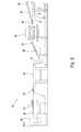
- FIG. 2is a schematic diagram of part of a continuous process for making the resilient floor tile of FIG. 1 .
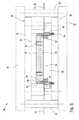
- FIG. 3is a partial sectional view of a press die containing a die assembly wherein the press die is shown in an open position.
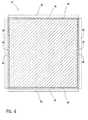
- FIG. 4is a plan view of a support block of the die assembly of FIG. 3 .
- FIG. 5is a partial sectional view of the press die containing the die assembly wherein the press die is shown in a closed position.
- FIG. 6is an enlarged sectional view of a cutting tool and a forming tool of the press die of FIG. 5 .
- FIG. 7is a partial plan view of a floating floor system incorporating the resilient floor tile.
- FIG. 8is a partial plan view of an alternate embodiment of the floating floor system incorporating the resilient floor tile.
- FIG. 1shows a resilient floor tile 1 according to an embodiment of the present invention.
- the resilient floor tile 1comprises a base layer 2 , a film layer 3 , a decorative film layer 4 , and a topcoat 5 .
- the base layer 2has a top surface 7 and a bottom surface 8 .
- Substantially vertical side walls 9extend between the top surface 7 and the bottom surface 8 .
- Each of the side walls 9has a recessed portion 10 formed in a side thereof.
- the recessed portion 10is substantially concave in shape and has a depth 11 , for example, of up to about 20 mils and, more preferably, about 15-20 mils.
- side walls 9 shown and described hereinare provided with the recessed portion 10 , it will be appreciated by those skilled in the art that the side walls 9 may alternatively be formed without the recessed portion 10 by varying the composition of the base layer 2 and/or the method of making the resilient floor tile 1 .
- the base layer 2comprises a binder, a filler, and an optional pigment.
- the bindermay be, for example, a polymeric resin, such as a vinyl resin, mixed with a plasticizer and a stabilizer.
- the polymeric resinmay include, for example, a homoploymer, a copolymer or a combination thereof.
- the homopolymermay include, for example, polyvinyl chloride, polyvinyl acetate, polyvinyl propionate, polyvinyl butyrate, polymerized vinylidene chloride, polymerized acrylic acid, polymerized ethyl acrylate, polymerized methyl acrylate, polymerized propyl acrylate, polymerized butyl acrylate, polyethylene, polypropylene, or mixtures thereof.
- the copolymermay include, for example, polyvinyl chloride/polyvinyl acetate, vinylidene chloride/vinyl chloride, methyl methacrylate/vinyl chloride, methyl acrylate/ethyl acrylate, ethyl acrylate/butyl acrylate copolymer, ethylene propylene copolymers, ethylene styrene copolymers, or mixtures thereof.
- the plasticizermay include, for example, ester type plasticizers, such as tributyl phosphate, dioctyl phthalate, dipropylene glycol dibenzoate, phenyl phosphate, dibutyl tartrate, amyl tartrate, butyl benzyl benzoate, dibutyl sebacate, dioctyl adipate, or didecyl adipate, rubbery plasticizers, such as butadiene-styrene copolymer, butadiene-acrylonitrile copolymer, or ethylene vinyl acetate, or other materials which function as plasticizers, such as epoxidized drying oils and aromatic hydrocarbon condensates. Where certain flexible soft vinyl resins are used, such as polymers containing large proportions of ethyl acrylate, no plasticizer may be needed.
- the stabilizermay include, for example, a mixed metal stabilizer, such as a calcium-zinc composition.
- the fillermay include, for example, an inorganic or organic material, such as calcium carbonate, magnesium carbonate, silica, diatomaceous earth, dolomite, clay, or mixtures thereof.
- the fillermay be a recyclable or renewable material.
- the optional pigmentmay include, for example, titanium dioxide, iron oxides, phthalocyanine blue, phthalocyanine green, azo red, benzidene yellow, carbon black, or mixtures thereof.
- the base layer 2may have a thickness of about 95-166 mils.
- the formulation of the base layer 2contains, for example, less than about 36% weight of the binder, preferably less than about 25% weight of the binder, and more preferably about 20-25% weight of the binder. Additionally, the base layer 2 contains for example, at least about 64% weight of the filler, preferably at least about 75% weight of the filler, and more preferably about 75-80% weight of the filler. Table 1 illustrates several examples of formulations for the base layer 2 .
- the film layer 3is disposed on the top surface 11 of the base layer 2 .
- the film layer 3has a thickness of about 2-4 mils.
- the film layer 3may consist, for example, of a polymeric vinyl film.
- the film layer 3is a substantially opaque white film. It will be appreciated by those skilled in the art, however, that the film layer 3 may alternatively be clear or provided with a printed ink pattern on a surface thereof. Additionally, the film layer 3 could be omitted and/or a printed pattern could be provided directly on the top surface 7 of the base layer 7 .
- the decorative film layer 4is disposed on a top surface of the film layer 3 .
- the decorative film layer 4has a thickness of about 2-3 mils.
- the decorative film layer 4may consist, for example, of a polymeric vinyl film.
- the decorative film layer 4is provided with a printed ink pattern on a back surface thereof.
- the decorative film layer 4is positioned on the film layer 3 , such that the printed ink pattern faces the film layer 3 .
- the decorative film layer 4may alternatively be clear or provided with a printed ink pattern on a top surface thereof. Additionally, the decorative film layer 4 could be omitted.
- the decorative film layer 4may also optionally be mechanically and/or chemically embossed. Because mechanical and chemical embossing of film layers is well known in the art, further description thereof has been omitted.
- the topcoat 5is provided on a top surface of the decorative film layer 4 .
- the topcoat 5has a thickness of about 1-2 mils.
- the topcoat 5may be, for example, a radiation curable coating, such as acrylated urethane or acrylated polyester.
- the topcoat 5may be a radiation curable biobased coating comprising a biobased component.
- the biobased componentmay be, for example, a biobased polyol, acylated biobased polyol, or biobased resin derived, for example, from renewable and/or biobased materials, such as plant oils, polyester, polyester-ether, vegetable oils, corn, cellulose, starch, sugar, or sugar alcohols.
- the topcoat 5may also comprise additional components, such as particles, which provide performance enhancement and/or texture to the topcoat 5 .
- the particlesmay include, for example, aluminum oxide particles, nylon particles, and the like. It will be appreciated by those skilled in the art that although the topcoat 5 is shown and described herein as being a single layer topcoat that the topcoat 5 could alternatively be a multiple layer topcoat. Additionally, the resilient floor tile 1 could be provided without the topcoat 5 .
- the resilient floor tile 1has a shaped edge 6 formed at an upper surface 13 of the resilient floor tile 1 that extends about a perimeter thereof.
- the shaped edge 6extends around the entire perimeter of the resilient floor tile 1 .
- the shaped edge 6could also extend around a portion of the perimeter of the resilient floor tile 1 .
- the shaped edge 6is substantially rounded or convex.
- the shaped edge 6could have other geometric configurations, for example, the shaped edge 6 could be beveled, stepped, scalloped, or concave or could consist of a combination of geometric configurations.
- the film layer 3 , decorative film layer 4 , and topcoat 5extend over at least a portion of the shaped edge 6 , and preferably, over the entirety of the shaped edge 6 . In other words, it is preferable that the film layer 3 , decorative film layer 4 , and topcoat 5 extend to an end portion 12 of the shaped edge 6 where the shaped edge 6 meets the side wall 8 of the base layer 2 .
- the resilient floor tile 1has a substantially square shape and a thickness of about 100-175 mils. It will be appreciated by those skilled in the art, however, that the resilient floor tile 1 is not limited to the structure shown and described herein.
- the resilient floor tile 1may comprise additional base layers, film layers, decorative film layers, and or topcoats.
- the thickness and the geometrical configuration of the resilient floor tile 1may be varied depending on the desired structural characteristics of the resilient floor tile 1 .
- the thickness of the base layer 2 , the film layer 3 , the decorative film layer 4 , and/or the topcoat 5may be varied.
- the shape of the resilient floor tile 1may alternatively be rectangular, round, oval, triangular, or the like.
- the method of making the resilient floor tile 1is a continuous process 20 , which is shown in part in FIG. 2 .
- the continuous processbegins with the binder, the filler, and the pigment being individually weighed and blended together at an ambient temperature of about 60-100 degrees Fahrenheit for about 5-10 minutes.
- the blend of the binder, the filler, and the pigmentare then mixed in a continuous mixer at a temperature of about 350-400 degrees Fahrenheit for about 15-30 seconds to form a fused mixture.
- the fused mixtureis then conveyed to a two roll mill. Using the two roll mill, the fused mixture is rolled out into a continuous sheet 21 that forms the base layer 2 of the resilient floor tile 1 .
- the continuous sheet 21As the continuous sheet 21 exits the two roll mill, the continuous sheet 21 is deposited onto a conveyor belt 22 , which supports the continuous sheet 21 as the continuous sheet 21 is conveyed to a first processing station where the film layer 3 is laminated to the top surface 7 .
- the conveyor belt 22then conveys the continuous sheet 21 to a second processing station where the decorative film layer 4 is laminated to the film layer 3 .
- the conveyor belt 22conveys the continuous sheet 21 to a third processing station where the continuous sheet 21 is mechanically embossed. From the time the continuous sheet 21 exits the two roll mill until after the continuous sheet 21 is mechanically embossed, the continuous sheet 21 is maintained at a constant temperature of about 300-320 degrees Fahrenheit.
- the conveyor belt 22conveys the continuous sheet 21 through a water bath 23 .
- the water bath 23consists, for example, of a chamber that is flooded with a coolant, such as water.
- the water bath 23cools the continuous sheet 21 to a temperature of about 135-145 degrees Fahrenheit.
- the conveyor belt 22conveys the continuous sheet 21 to a water removal station 24 .
- the coolantis removed from the continuous sheet 21 , as well as the conveyor belt 22 , by blowing air onto the upper surface of the continuous sheet 21 .
- the continuous sheet 21is transferred from the conveyor belt 22 to a press die conveyor 26 .
- the continuous sheet 21passes through a drying station 25 .
- the drying station 25blows air onto the upper surface of the continuous sheet 21 while a lower surface of the continuous sheet 21 is drawn across a squeegee. Additionally or alternatively, air could be blown onto the lower surface of the continuous sheet 21 .
- the continuous sheet 22could alternatively be processed on a drum line instead of on the conveyor belt 22 .
- the application of the film layer 3 , the application of the decorative film layer 4 , the mechanical embossing, and/or the cooling of the continuous sheet 21could take place on the drum line.
- the method of processing resilient floor tiles on drum linesis well known in the art and is shown and described, for example, in U.S. Pat. Nos. 4,804,429, 6,333,076, and 6,440,500, which are hereby incorporated by reference in their entireties.
- the continuous sheet 21is transferred onto the press die conveyor 26 , which conveys the continuous sheet 21 into a processing loop 27 .
- the continuous sheet 21is then conveyed up an infeed support 28 and into a press die 40 by infeed rollers 29 and outfeed rollers 30 .
- the processing loop 27can vary in size and compensates for variances in processing times between the press die 40 and the processing steps prior thereto.
- the continuous sheet 21is between about 130-140 degrees Fahrenheit, and more preferable about 135 degrees Fahrenheit.
- FIGS. 3-6show the press die 40 .
- the press die 40cuts and forms the continuous sheet 21 into individual tiles 31 that form the resilient floor tiles 1 .
- FIG. 3shows the press die 40 in an open position
- FIG. 5shows the press die 40 in a closed position.
- the press die 40includes an upper platen 61 and a lower platen 42 separated by press posts 43 .
- the upper platen 61is moveable with respect to the lower platen 42 along the press posts 43 via hydraulics (not shown) or, alternatively, electrical or mechanical means.
- a die assembly 44is arranged between the upper platen 61 and the lower platen 42 .
- the die assembly 44comprises an upper die shoe 41 attached to the upper platen 61 and a lower die shoe 46 attached to the lower platen 42 .
- An upper die member 45is attached to the upper die shoe 41 .
- a support block 47is attached to the upper die member 45 .
- the support block 47is provided with a forming tool 48 , a cutting tool 49 , and a knife support block 50 .
- the upper die 47has a substantially square shape and may be formed, for example, of a block of metal.
- the forming tool 48is provided in four separate parts each being removeably attached to a side of the support block 47 substantially about a perimeter thereof.
- the forming tool 48may be removeably attached to the support block 47 , for example, with any known attachment mechanism (not shown), such as a screw or the like. As best shown in FIG.
- the forming tool 48is provided with a shaped surface 51 configured to correspond to the desired size and dimension of the shaped edge 6 of the resilient tile 1 .
- the shaped surface 51is substantially rounded or convex.
- the shaped surface 51could have other geometric configurations, for example, the shaped surface 51 could be beveled, stepped, scalloped, or concave or could consist of a combination of geometric configurations.
- the cutting tool 49is provided in four separate parts each being removeably attached to the side of the support block 47 substantially about a perimeter thereof.
- the cutting tool 49is attached to the support block 47 such that the cutting tool 49 abuts the forming tool 48 .
- the cutting tool 49may be removeably attached to the support block 47 , for example, with any known attachment mechanism (not shown), such, as a screw or the like.
- the cutting tool 49is provided with a substantially inclined blade 52 positioned opposite the shaped edge 51 of the forming tool 48 such that the blade 52 inclines toward the shaped edge 51 of the forming tool 48 .
- the blade 52is inclined at an angle of about 30 degrees. However, it will be appreciated by those skilled in the art that the angle of the blade 52 may be varied depending on the desired configuration of the resilient floor tile 1 .
- the knife support block 50is provided in four separate parts each being removeably attached to the cutting tool 49 substantially about a perimeter thereof. As best shown in FIG. 6 , the knife support block 50 is attached to the cutting tool 49 such that the knife support block 50 abuts the cutting tool 49 .
- the knife support block 50may be removeably attached to the cutting tool 49 , for example, with any known attachment mechanism (not shown), such as a screw or the like.
- a stripper plate 53is attached to a bottom surface of the support block 47 in an area inside the forming tool 48 .
- the stripper plate 53is attached to the support block 47 via springs 54 such that the stripper plate 53 moves toward the support block 47 when the springs 54 are compressed.
- a clearance 60is provided between a side of the stripper plate 53 and a side of the forming tool 48 to enable the stripper plate 53 to easily move relative thereto.
- a lower die 55is attached to the lower die shoe 46 .
- the lower die 55has a substantially flat support surface 56 facing the support block 47 .
- Carbides 57form a provided perimeter of the lower die 55 .
- a frame scrap support plate 58is attached adjacent to the lower die 55 via springs 59 such that the frame scrap support plate 58 moves away from the support block 47 when the springs 59 are compressed.
- the continuous sheet 21consisting of the base layer 2 , the film layer 3 , and the decorative film layer 4 is drawn into the press die 40 by the infeed rollers 28 and the outfeed rollers 29 shown in FIG. 2 .
- the continuous sheet 21is supported on the support surface 56 of the lower die 55 .
- the infeed rollers 28 and the outfeed rollers 29stop advancing the continuous sheet 21 , and the press die 40 is actuated to move the press die 40 from the open position to the closed position, as shown in FIG. 5 .
- the blade 52 of the cutting tool 49cuts the continuous sheet 21 to form the side walls 9 of the resilient floor tile 1 while the forming tool 48 concurrently forms the shaped edge 6 on the perimeter of the upper surface 13 of the resilient floor tile 1 , as best shown in FIG. 6 .
- the stripper plate 53moves toward the support block 47 , as a result of the springs 54 being compressed.
- the frame scrap support plate 58moves away from the support block 47 , as a result of the springs 59 being compressed.
- the cutting tool 49is able to easily cut the continuous sheet 21 .
- the frame scrap support plate 58also supports any frame scrap 32 cut from the continuous sheet 21 during the cutting and forming of the individual tile 31 .
- the press die 40applies about 23 tons of pressure to the continuous sheet 21 for a period of about 0.25 seconds.
- the press die 40is returned to the open position.
- the stripper plate 53is pushed downwards and back to its original position by the springs 54 .
- the stripper plate 53eases the individual tile 31 from the forming tool 48 .
- the frame scrap support plate 58is pushed upwards by the springs 59 allowing the individual tile 31 to be positioned within the frame scrap 32 for subsequent removal from the press die 40 .
- the infeed rollers 28 and the outfeed rollers 29then advance the individual tile 31 and the frame scrap 32 out of the press die 40 .
- the individual tile 31 and the frame scrap 32are advanced out of the press die 40 , the individual tile 31 is separated from the frame scrap 32 and is conveyed onto a tile conveyor 33 while the frame scrap 32 is conveyed onto a separate scrap conveyor 34 that conveys the frame scrap 32 to a scrap recycle station.
- the infeed rollers 28 and the outfeed rollers 29continue to advance the individual tile 31 and the frame scrap 32 until an uncut portion of the trailing continuous sheet 21 has been positioned in the press die 40 .
- the press die 40is then re-actuated to form another one of the individual tiles 31 . This process is repeated for the remainder of the continuous sheet 21 .
- the tile conveyor 33optionally conveys the individual tiles 31 to a brushing station.
- the brushing stationcomprises, for example, at least two rotary brushes.
- the rotary brushesmay have a diameter, for example, of about 4.5 inches.
- Each of the rotary brushesis provided with a plurality of rows of bristles.
- Each of the bristlesmay have a diameter of about 60 mils and may be made, for example, from a material such as nylon.
- the rotary brushesare positioned such that the bristles extend substantially perpendicular to the side walls 9 of the individual tiles 31 .
- the rotary brushesare rotated such that the bristles contact the individual tiles 31 with a downward motion.
- the bristlescontact the upper surface 13 of the individual tiles 31 and then are rotated downward toward the bottom surface 8 of the individual tiles 31 .
- the bristlesbrush the side walls 9 of the individual tiles 31 in a downward direction to correct and/or reposition any lifted corners on the individual tiles 31 and to remove loose film hairs, debris, and the like from the individual tiles 31 .
- the individual tiles 31may be conveyed through the brushing station such that one set of the opposing side walls 9 of the individual tiles 31 are contacted by the brushes and then the individual tiles 31 and/or the brushes can be rotated such that the other set of the opposing side walls 9 of the individual tiles 31 are contacted by the brushes.
- the tile conveyor 33then optionally conveys the individual tiles 31 to a coating station.
- the topcoat 5is provided overtop of the decorative film layer 4 to complete the formation of the resilient floor tile 1 .
- the topcoat 5may be coated, for example, in a liquid or flowable form onto the decorative film layer 4 and then cured. It is known to cure the topcoat 5 by controlled exposure to radiation, such as ultraviolet or electron beam radiation.
- the resilient floor tile 1is then conveyed to an inspection station and a stacking station where the resilient floor tile 1 is subsequently packaged.
- the individual tiles 31could be conveyed by the tile conveyor 33 directly to an inspection, stacking, and/or packaging station.
- FIGS. 7-8show a floating floor system 70 comprising a plurality of the resilient floor tiles 1 installed on a sub-floor 71 .
- a liner 72is provided on the sub-floor 71 .
- the liner 72may be, for example, made from felt, vinyl, or glass and may optionally be coated or impregnated with a plastisol.
- the liner 72is provided on the sub-floor 71 such that the liner 72 is not attached to the sub-floor 71 by an adhesive or any other means.
- An adhesive 73is provided on a top surface of the liner 72 .
- the resilient floor tiles 1are then positioned on the adhesive 73 such that a space 74 is created between the side walls 8 of the adjacent resilient floor tiles 1 .
- Grout 75is then provided in the space 74 .
- the grout 75may be, for example, any conventional flooring grout.
- the grout 75is provided in the space such that the grout is substantially below the upper surface 13 of the resilient floor tile.
- the recessed portions 10 in the side walls 9 of the resilient floor tiles 1provide an undercut, which provides additional area for the grout 75 to bond to the side walls 9 of the resilient floor tiles 1 .
- the floating floor system 70has the appearance of a flooring system formed from ceramic or natural tile.
- FIG. 8shows an alternate embodiment of the floating floor system 70 .
- the resilient floor tiles 1may alternatively be adhered to the liner 72 in a butt-fit arrangement such that the shaped edges 6 of the adjacent floor tiles 1 are positioned against each other.
- the resilient floor tiles 1 or the liner 72 shown in FIGS. 7-8may be alternatively adhered directly to the sub-floor 71 .
Landscapes
- Engineering & Computer Science (AREA)
- Architecture (AREA)
- Civil Engineering (AREA)
- Structural Engineering (AREA)
- Mechanical Engineering (AREA)
- Life Sciences & Earth Sciences (AREA)
- Forests & Forestry (AREA)
- Floor Finish (AREA)
Abstract
Description
| TABLE 1 |
| Base Layer Formulations |
| EX-1 | EX-2 | EX-3 | |||
| Percent by | Percent by | Percent by | |||
| Component | Weight | Weight | Weight | ||
| Homopolymer | 11.0 | 12.1 | 10.05 | ||
| Copolymer | 3.8 | 4.2 | 4.01 | ||
| Plasticizer | 4.9 | 5.4 | 5.68 | ||
| Stabilizer | 0.3 | 0.3 | 0.27 | ||
| Filler | 78.7 | 76.7 | 78.87 | ||
| Pigment | 1.3 | 1.3 | 1.12 | ||
| Total | 100 | 100 | 100 | ||
Claims (18)
Priority Applications (2)
| Application Number | Priority Date | Filing Date | Title |
|---|---|---|---|
| US12/854,942US8741085B2 (en) | 2009-08-21 | 2010-08-12 | Method of making a resilient floor tile |
| US14/259,237US20140227491A1 (en) | 2009-08-21 | 2014-04-23 | Resilient floor tile and method of making the same |
Applications Claiming Priority (2)
| Application Number | Priority Date | Filing Date | Title |
|---|---|---|---|
| US23573309P | 2009-08-21 | 2009-08-21 | |
| US12/854,942US8741085B2 (en) | 2009-08-21 | 2010-08-12 | Method of making a resilient floor tile |
Related Child Applications (1)
| Application Number | Title | Priority Date | Filing Date |
|---|---|---|---|
| US14/259,237ContinuationUS20140227491A1 (en) | 2009-08-21 | 2014-04-23 | Resilient floor tile and method of making the same |
Publications (2)
| Publication Number | Publication Date |
|---|---|
| US20110041989A1 US20110041989A1 (en) | 2011-02-24 |
| US8741085B2true US8741085B2 (en) | 2014-06-03 |
Family
ID=43604342
Family Applications (2)
| Application Number | Title | Priority Date | Filing Date |
|---|---|---|---|
| US12/854,942Expired - Fee RelatedUS8741085B2 (en) | 2009-08-21 | 2010-08-12 | Method of making a resilient floor tile |
| US14/259,237AbandonedUS20140227491A1 (en) | 2009-08-21 | 2014-04-23 | Resilient floor tile and method of making the same |
Family Applications After (1)
| Application Number | Title | Priority Date | Filing Date |
|---|---|---|---|
| US14/259,237AbandonedUS20140227491A1 (en) | 2009-08-21 | 2014-04-23 | Resilient floor tile and method of making the same |
Country Status (1)
| Country | Link |
|---|---|
| US (2) | US8741085B2 (en) |
Cited By (2)
| Publication number | Priority date | Publication date | Assignee | Title |
|---|---|---|---|---|
| US20140360117A1 (en)* | 2012-01-06 | 2014-12-11 | Lg Hausys, Ltd. | Flooring using pvc and method of constructing the flooring |
| US20190240856A1 (en)* | 2018-02-06 | 2019-08-08 | Toyota Jidosha Kabushiki Kaisha | Cutting apparatus for membrane electrode and gas diffusion layer assembly |
Families Citing this family (10)
| Publication number | Priority date | Publication date | Assignee | Title |
|---|---|---|---|---|
| US20140255659A1 (en)* | 2011-10-31 | 2014-09-11 | Wpt Gmbh | Plastic floor covering |
| GB2546746B (en)* | 2016-01-26 | 2020-04-01 | Reco Surfaces Ltd | Method for mounting wall panels & wall panel system |
| DE102016201433A1 (en) | 2016-02-01 | 2017-08-03 | Bayerische Motoren Werke Aktiengesellschaft | Method for processing and / or producing a component |
| US11559961B2 (en)* | 2019-09-17 | 2023-01-24 | Daltile Corporation | Pressing equipment, a plant and a method for forming a floor element |
| US20240239132A1 (en)* | 2021-05-12 | 2024-07-18 | Unilin, Bv | Methods for manufacturing a decorative panel, and decorative panels |
| PL4088949T3 (en)* | 2021-05-12 | 2025-09-01 | Unilin, Bv | Methods for manufacturing a decorative panel |
| EP4088950A1 (en)* | 2021-05-12 | 2022-11-16 | Flooring Industries Limited, SARL | Methods for manufacturing a decorative panel |
| US12162179B2 (en)* | 2022-06-30 | 2024-12-10 | Shaw Industries Group, Inc. | System and method for plank processing |
| KR20250067139A (en)* | 2022-09-07 | 2025-05-14 | 뵈린게 이노베이션 에이비이 | Slopes on building panels and methods for manufacturing such building panels |
| TWI852655B (en)* | 2023-06-30 | 2024-08-11 | 友達光電股份有限公司 | Lamination apparatus and lamination method |
Citations (15)
| Publication number | Priority date | Publication date | Assignee | Title |
|---|---|---|---|---|
| US3616144A (en) | 1966-07-21 | 1971-10-26 | Dunlop Co Ltd | Wall-covering elements |
| US4219598A (en) | 1974-08-06 | 1980-08-26 | Sanyo Electric Co., Ltd. | Molded article, the method for manufacturing the same and the dies therefor |
| US4312686A (en) | 1980-02-11 | 1982-01-26 | American Biltrite Inc. | Printed and embossed floor covering and method and apparatus for its manufacture |
| US4614556A (en) | 1984-04-16 | 1986-09-30 | Armstrong World Industries, Inc. | Method for making decorative product |
| US4678528A (en) | 1985-03-05 | 1987-07-07 | American Biltrite, Inc. | Method and apparatus for making a printed and embossed floor covering using a cast wear layer |
| US4772500A (en) | 1985-05-20 | 1988-09-20 | Mondo Rubber S.P.A. | Covering of synthetic material in the form of tiles and a method for its manufacture |
| US4804429A (en) | 1987-12-11 | 1989-02-14 | Armstrong World Industries, Inc. | Method of forming a floor tile on a drum |
| US5077112A (en) | 1990-04-12 | 1991-12-31 | Armstrong World Industries, Inc. | Floor covering with inorganic wear layer |
| US5188876A (en) | 1990-04-12 | 1993-02-23 | Armstrong World Industries, Inc. | Surface covering with inorganic wear layer |
| US5962111A (en)* | 1996-08-13 | 1999-10-05 | Mac Dermid, Incorporated | Compressible printing plates and manufacturing process therefor |
| US6333076B1 (en) | 1999-07-28 | 2001-12-25 | Armstrong World Industries, Inc. | Composition and method for manufacturing a surface covering product having a controlled gloss surface coated wearlayer |
| US6783720B2 (en)* | 1999-10-04 | 2004-08-31 | Fort James Corporation | Punch stripper ring knock-out for pressware die sets |
| US20060043633A1 (en) | 2003-04-30 | 2006-03-02 | Robert Dempsey | Resilient floor tile and method for making same |
| US20060083902A1 (en) | 2003-04-30 | 2006-04-20 | Jarosz Dennis P | Resilient floor tile and method for making same |
| US20080119604A1 (en) | 2006-11-20 | 2008-05-22 | Greenawalt Thomas P | Non-or reduced PVC copolymer vinyl composition tile |
Family Cites Families (5)
| Publication number | Priority date | Publication date | Assignee | Title |
|---|---|---|---|---|
| GB9525851D0 (en)* | 1995-08-15 | 1996-02-21 | Pollitt Clifford B | Improvements in or relating to surfaces |
| US7014802B1 (en)* | 1997-02-20 | 2006-03-21 | Mannington Mills, Of Delaware, Inc. | Methods to make a surface covering having a natural appearance |
| US6921791B2 (en)* | 2002-05-07 | 2005-07-26 | Awi Licensing Company | Thermoplastic elastomer |
| US20040229020A1 (en)* | 2003-05-14 | 2004-11-18 | Laborde Paul Timothy | Corrosion resistant tile and protective tiling system |
| US7175904B2 (en)* | 2003-08-28 | 2007-02-13 | Congoleum Corporation | Non-vinyl flooring and method for making same |
- 2010
- 2010-08-12USUS12/854,942patent/US8741085B2/ennot_activeExpired - Fee Related
- 2014
- 2014-04-23USUS14/259,237patent/US20140227491A1/ennot_activeAbandoned
Patent Citations (19)
| Publication number | Priority date | Publication date | Assignee | Title |
|---|---|---|---|---|
| US3616144A (en) | 1966-07-21 | 1971-10-26 | Dunlop Co Ltd | Wall-covering elements |
| US4219598A (en) | 1974-08-06 | 1980-08-26 | Sanyo Electric Co., Ltd. | Molded article, the method for manufacturing the same and the dies therefor |
| US4312686A (en) | 1980-02-11 | 1982-01-26 | American Biltrite Inc. | Printed and embossed floor covering and method and apparatus for its manufacture |
| US4614556A (en) | 1984-04-16 | 1986-09-30 | Armstrong World Industries, Inc. | Method for making decorative product |
| US4678528A (en) | 1985-03-05 | 1987-07-07 | American Biltrite, Inc. | Method and apparatus for making a printed and embossed floor covering using a cast wear layer |
| US4772500A (en) | 1985-05-20 | 1988-09-20 | Mondo Rubber S.P.A. | Covering of synthetic material in the form of tiles and a method for its manufacture |
| US4804429A (en) | 1987-12-11 | 1989-02-14 | Armstrong World Industries, Inc. | Method of forming a floor tile on a drum |
| US5188876A (en) | 1990-04-12 | 1993-02-23 | Armstrong World Industries, Inc. | Surface covering with inorganic wear layer |
| US5077112A (en) | 1990-04-12 | 1991-12-31 | Armstrong World Industries, Inc. | Floor covering with inorganic wear layer |
| US5962111A (en)* | 1996-08-13 | 1999-10-05 | Mac Dermid, Incorporated | Compressible printing plates and manufacturing process therefor |
| US6333076B1 (en) | 1999-07-28 | 2001-12-25 | Armstrong World Industries, Inc. | Composition and method for manufacturing a surface covering product having a controlled gloss surface coated wearlayer |
| US6440500B1 (en) | 1999-07-28 | 2002-08-27 | Armstrong World Industries, Inc. | Method for manufacturing a surface covering product having a controlled gloss surface coated wearlayer |
| US6783720B2 (en)* | 1999-10-04 | 2004-08-31 | Fort James Corporation | Punch stripper ring knock-out for pressware die sets |
| US20060043633A1 (en) | 2003-04-30 | 2006-03-02 | Robert Dempsey | Resilient floor tile and method for making same |
| US20060083902A1 (en) | 2003-04-30 | 2006-04-20 | Jarosz Dennis P | Resilient floor tile and method for making same |
| US7550192B2 (en) | 2003-04-30 | 2009-06-23 | Congoleum Corporation | Resilient floor tile |
| US20090186197A1 (en) | 2003-04-30 | 2009-07-23 | Congleum Corporation | Resilient floor tile and method of making same |
| US20100146895A1 (en) | 2003-04-30 | 2010-06-17 | Congleum Corporation | Resilient floor tile and method of making same |
| US20080119604A1 (en) | 2006-11-20 | 2008-05-22 | Greenawalt Thomas P | Non-or reduced PVC copolymer vinyl composition tile |
Cited By (3)
| Publication number | Priority date | Publication date | Assignee | Title |
|---|---|---|---|---|
| US20140360117A1 (en)* | 2012-01-06 | 2014-12-11 | Lg Hausys, Ltd. | Flooring using pvc and method of constructing the flooring |
| US20190240856A1 (en)* | 2018-02-06 | 2019-08-08 | Toyota Jidosha Kabushiki Kaisha | Cutting apparatus for membrane electrode and gas diffusion layer assembly |
| US11040460B2 (en)* | 2018-02-06 | 2021-06-22 | Toyota Jidosha Kabushiki Kaisha | Cutting apparatus for membrane electrode and gas diffusion layer assembly |
Also Published As
| Publication number | Publication date |
|---|---|
| US20110041989A1 (en) | 2011-02-24 |
| US20140227491A1 (en) | 2014-08-14 |
Similar Documents
| Publication | Publication Date | Title |
|---|---|---|
| US8741085B2 (en) | Method of making a resilient floor tile | |
| RU2729571C2 (en) | Facing panels custom-made by digital printing on the base panel | |
| US7550192B2 (en) | Resilient floor tile | |
| EP3526422B1 (en) | A dimensionally stable floor panel | |
| US9127459B2 (en) | Surface covering tiles having an edge treatment for assembly that allows for grouting | |
| CN114829472A (en) | Multilayer floor based on PVC (polyvinyl chloride) plastisol | |
| KR102128607B1 (en) | Multi-layer solid tile and process for the preparation thereof | |
| US20240075730A1 (en) | Methods to manufacture a building panel with bevel | |
| US20050221056A1 (en) | Multi-layered plastic strip or plate having a three-dimensional optical aspect, method for the production and use thereof | |
| US20070202305A1 (en) | Floor including wood powder and method of manufacturing the same | |
| EP1951527A2 (en) | Resilient floor tile and method for making same | |
| EP1838510B1 (en) | Homogenous surface covering | |
| US20230382096A1 (en) | A method to produce a laminated substrate with an embossed structure | |
| US20160279912A1 (en) | Dimensionally stable product and process of fabricating a dimensionally stable product | |
| US20240342977A1 (en) | Floor plank modification system | |
| US20050167031A1 (en) | Homogeneous amorphous marble flooring and process of making the same | |
| US20250010534A1 (en) | Method for manufacturing panels | |
| US20230382099A1 (en) | Method to produce a panel with an embossed structure | |
| US20230311471A1 (en) | Method to produce a laminated substrate and such a laminated substrate | |
| KR102176175B1 (en) | Flooring tile for telegraph elimination and a process for the preparation thereof | |
| HK40004561A (en) | A dimensionally stable floor panel | |
| HK40013928B (en) | A dimensionally stable floor panel | |
| HK40013928A (en) | A dimensionally stable floor panel |
Legal Events
| Date | Code | Title | Description |
|---|---|---|---|
| AS | Assignment | Owner name:ARMSTRONG WORLD INDUSTRIES, INC., PENNSYLVANIA Free format text:ASSIGNMENT OF ASSIGNORS INTEREST;ASSIGNORS:ANSPACH, KEAN M.;BAIR, THOMAS C.;ESHBACH, JOHN R., JR.;REEL/FRAME:024827/0206 Effective date:20100811 | |
| AS | Assignment | Owner name:AWI LICENSING COMPANY, DELAWARE Free format text:ASSIGNMENT OF ASSIGNORS INTEREST;ASSIGNOR:ARMSTRONG WORLD INDUSTRIES, INC.;REEL/FRAME:032632/0356 Effective date:20140404 | |
| STCF | Information on status: patent grant | Free format text:PATENTED CASE | |
| AS | Assignment | Owner name:AFI LICENSING LLC, PENNSYLVANIA Free format text:ASSIGNMENT OF ASSIGNORS INTEREST;ASSIGNOR:AWI LICENSING COMPANY;REEL/FRAME:038629/0767 Effective date:20160328 | |
| AS | Assignment | Owner name:BANK OF AMERICA, N.A., AS COLLATERAL AGENT, NEW YORK Free format text:SECURITY INTEREST;ASSIGNOR:AFI LICENSING LLC;REEL/FRAME:040381/0180 Effective date:20160401 Owner name:BANK OF AMERICA, N.A., AS COLLATERAL AGENT, NEW YO Free format text:SECURITY INTEREST;ASSIGNOR:AFI LICENSING LLC;REEL/FRAME:040381/0180 Effective date:20160401 | |
| MAFP | Maintenance fee payment | Free format text:PAYMENT OF MAINTENANCE FEE, 4TH YEAR, LARGE ENTITY (ORIGINAL EVENT CODE: M1551) Year of fee payment:4 | |
| AS | Assignment | Owner name:AFI LICENSING LLC, PENNSYLVANIA Free format text:RELEASE BY SECURED PARTY;ASSIGNOR:BANK OF AMERICA, N.A., AS COLLATERAL AGENT;REEL/FRAME:047996/0459 Effective date:20181231 | |
| AS | Assignment | Owner name:BANK OF AMERICA, N.A., AS COLLATERAL AGENT, NORTH CAROLINA Free format text:SECURITY INTEREST;ASSIGNOR:AFI LICENSING LLC;REEL/FRAME:047999/0554 Effective date:20181231 Owner name:BANK OF AMERICA, N.A., AS COLLATERAL AGENT, NORTH Free format text:SECURITY INTEREST;ASSIGNOR:AFI LICENSING LLC;REEL/FRAME:047999/0554 Effective date:20181231 | |
| AS | Assignment | Owner name:BANK OF AMERICA, N.A., AS COLLATERAL AGENT, NORTH CAROLINA Free format text:CORRECTIVE ASSIGNMENT TO CORRECT THE PROPERTY NUMBERS PREVIOUSLY RECORDED AT REEL: 47999 FRAME: 554. ASSIGNOR(S) HEREBY CONFIRMS THE ASSIGNMENT;ASSIGNOR:AFI LICENSING LLC;REEL/FRAME:052804/0921 Effective date:20181231 | |
| AS | Assignment | Owner name:PATHLIGHT CAPITAL, LP, MASSACHUSETTS Free format text:SECURITY INTEREST;ASSIGNORS:ARMSTRONG FLOORING, INC.;AFI LICENSING, LLC;REEL/FRAME:053033/0726 Effective date:20200623 | |
| AS | Assignment | Owner name:BANK OF AMERICA, N.A., AS COLLATERAL AGENT, NORTH CAROLINA Free format text:SECURITY INTEREST;ASSIGNOR:AFI LICENSING LLC;REEL/FRAME:053731/0016 Effective date:20200623 | |
| FEPP | Fee payment procedure | Free format text:MAINTENANCE FEE REMINDER MAILED (ORIGINAL EVENT CODE: REM.); ENTITY STATUS OF PATENT OWNER: LARGE ENTITY | |
| LAPS | Lapse for failure to pay maintenance fees | Free format text:PATENT EXPIRED FOR FAILURE TO PAY MAINTENANCE FEES (ORIGINAL EVENT CODE: EXP.); ENTITY STATUS OF PATENT OWNER: LARGE ENTITY | |
| STCH | Information on status: patent discontinuation | Free format text:PATENT EXPIRED DUE TO NONPAYMENT OF MAINTENANCE FEES UNDER 37 CFR 1.362 | |
| AS | Assignment | Owner name:AFI LICENSING LLC, PENNSYLVANIA Free format text:RELEASE BY SECURED PARTY;ASSIGNOR:BANK OF AMERICA, N.A.;REEL/FRAME:060934/0566 Effective date:20220725 Owner name:ARMSTRONG FLOORING, INC., PENNSYLVANIA Free format text:RELEASE BY SECURED PARTY;ASSIGNOR:BANK OF AMERICA, N.A.;REEL/FRAME:060934/0566 Effective date:20220725 Owner name:AFI LICENSING LLC, PENNSYLVANIA Free format text:RELEASE BY SECURED PARTY;ASSIGNOR:BANK OF AMERICA, N.A.;REEL/FRAME:060934/0554 Effective date:20220725 Owner name:ARMSTRONG FLOORING, INC., PENNSYLVANIA Free format text:RELEASE BY SECURED PARTY;ASSIGNOR:BANK OF AMERICA, N.A.;REEL/FRAME:060934/0554 Effective date:20220725 Owner name:AFI LICENSING LLC, PENNSYLVANIA Free format text:RELEASE BY SECURED PARTY;ASSIGNOR:PATHLIGHT CAPITAL LP;REEL/FRAME:060934/0242 Effective date:20220725 Owner name:ARMSTRONG FLOORING, INC., PENNSYLVANIA Free format text:RELEASE BY SECURED PARTY;ASSIGNOR:PATHLIGHT CAPITAL LP;REEL/FRAME:060934/0242 Effective date:20220725 | |
| FP | Lapsed due to failure to pay maintenance fee | Effective date:20220603 |