US8740850B2 - Safety catheter system and method - Google Patents
Safety catheter system and methodDownload PDFInfo
- Publication number
- US8740850B2 US8740850B2US13/225,229US201113225229AUS8740850B2US 8740850 B2US8740850 B2US 8740850B2US 201113225229 AUS201113225229 AUS 201113225229AUS 8740850 B2US8740850 B2US 8740850B2
- Authority
- US
- United States
- Prior art keywords
- needle
- tube
- locking
- insertion mechanism
- distal
- Prior art date
- Legal status (The legal status is an assumption and is not a legal conclusion. Google has not performed a legal analysis and makes no representation as to the accuracy of the status listed.)
- Expired - Lifetime, expires
Links
- 238000000034methodMethods0.000titleabstractdescription28
- 238000003780insertionMethods0.000claimsabstractdescription76
- 230000037431insertionEffects0.000claimsabstractdescription76
- 230000007246mechanismEffects0.000claimsabstractdescription62
- 239000000463materialSubstances0.000claimsdescription3
- 230000008878couplingEffects0.000claims1
- 238000010168coupling processMethods0.000claims1
- 238000005859coupling reactionMethods0.000claims1
- 230000002633protecting effectEffects0.000abstractdescription5
- 230000001681protective effectEffects0.000abstractdescription5
- 239000012530fluidSubstances0.000description24
- 210000003462veinAnatomy0.000description21
- 238000001990intravenous administrationMethods0.000description17
- 239000008280bloodSubstances0.000description15
- 210000004369bloodAnatomy0.000description15
- 238000013459approachMethods0.000description5
- 208000035473Communicable diseaseDiseases0.000description4
- 238000001802infusionMethods0.000description4
- 230000036541healthEffects0.000description3
- 208000015181infectious diseaseDiseases0.000description3
- 229920001296polysiloxanePolymers0.000description3
- 238000002360preparation methodMethods0.000description3
- 230000004888barrier functionEffects0.000description2
- 210000004204blood vesselAnatomy0.000description2
- 230000006835compressionEffects0.000description2
- 238000007906compressionMethods0.000description2
- 239000003814drugSubstances0.000description2
- 229940079593drugDrugs0.000description2
- 238000002347injectionMethods0.000description2
- 239000007924injectionSubstances0.000description2
- 230000000670limiting effectEffects0.000description2
- 230000002093peripheral effectEffects0.000description2
- 229920003023plasticPolymers0.000description2
- 230000002829reductive effectEffects0.000description2
- 210000003813thumbAnatomy0.000description2
- 208000035049Blood-Borne InfectionsDiseases0.000description1
- 241001631457CannulaSpecies0.000description1
- 241000725303Human immunodeficiency virusSpecies0.000description1
- 230000009471actionEffects0.000description1
- 239000002390adhesive tapeSubstances0.000description1
- 238000002512chemotherapyMethods0.000description1
- 239000002131composite materialSubstances0.000description1
- 238000011109contaminationMethods0.000description1
- 238000011161developmentMethods0.000description1
- 235000015872dietary supplementNutrition0.000description1
- 239000003792electrolyteSubstances0.000description1
- 229920002457flexible plasticPolymers0.000description1
- 210000005224forefingerAnatomy0.000description1
- 230000002458infectious effectEffects0.000description1
- 238000002642intravenous therapyMethods0.000description1
- 238000012423maintenanceMethods0.000description1
- 238000004519manufacturing processMethods0.000description1
- 230000013011matingEffects0.000description1
- 238000002483medicationMethods0.000description1
- 238000012986modificationMethods0.000description1
- 230000004048modificationEffects0.000description1
- 230000007935neutral effectEffects0.000description1
- 230000036961partial effectEffects0.000description1
- 230000000149penetrating effectEffects0.000description1
- 238000003825pressingMethods0.000description1
- 230000001902propagating effectEffects0.000description1
- 230000000452restraining effectEffects0.000description1
- 230000007480spreadingEffects0.000description1
- 238000003892spreadingMethods0.000description1
- 230000001954sterilising effectEffects0.000description1
- 238000002560therapeutic procedureMethods0.000description1
Images


Classifications
- A—HUMAN NECESSITIES
- A61—MEDICAL OR VETERINARY SCIENCE; HYGIENE
- A61M—DEVICES FOR INTRODUCING MEDIA INTO, OR ONTO, THE BODY; DEVICES FOR TRANSDUCING BODY MEDIA OR FOR TAKING MEDIA FROM THE BODY; DEVICES FOR PRODUCING OR ENDING SLEEP OR STUPOR
- A61M25/00—Catheters; Hollow probes
- A61M25/01—Introducing, guiding, advancing, emplacing or holding catheters
- A61M25/06—Body-piercing guide needles or the like
- A61M25/0612—Devices for protecting the needle; Devices to help insertion of the needle, e.g. wings or holders
- A61M25/0631—Devices for protecting the needle; Devices to help insertion of the needle, e.g. wings or holders having means for fully covering the needle after its withdrawal, e.g. needle being withdrawn inside the handle or a cover being advanced over the needle
- A—HUMAN NECESSITIES
- A61—MEDICAL OR VETERINARY SCIENCE; HYGIENE
- A61M—DEVICES FOR INTRODUCING MEDIA INTO, OR ONTO, THE BODY; DEVICES FOR TRANSDUCING BODY MEDIA OR FOR TAKING MEDIA FROM THE BODY; DEVICES FOR PRODUCING OR ENDING SLEEP OR STUPOR
- A61M39/00—Tubes, tube connectors, tube couplings, valves, access sites or the like, specially adapted for medical use
- A61M39/02—Access sites
- A61M39/04—Access sites having pierceable self-sealing members
- A61M39/045—Access sites having pierceable self-sealing members pre-slit to be pierced by blunt instrument
- A—HUMAN NECESSITIES
- A61—MEDICAL OR VETERINARY SCIENCE; HYGIENE
- A61M—DEVICES FOR INTRODUCING MEDIA INTO, OR ONTO, THE BODY; DEVICES FOR TRANSDUCING BODY MEDIA OR FOR TAKING MEDIA FROM THE BODY; DEVICES FOR PRODUCING OR ENDING SLEEP OR STUPOR
- A61M39/00—Tubes, tube connectors, tube couplings, valves, access sites or the like, specially adapted for medical use
- A61M39/22—Valves or arrangement of valves
- A61M39/26—Valves closing automatically on disconnecting the line and opening on reconnection thereof
- A61M2039/262—Valves closing automatically on disconnecting the line and opening on reconnection thereof having a fluid space within the valve remaining the same upon connection and disconnection, i.e. neutral-drawback valve
- A—HUMAN NECESSITIES
- A61—MEDICAL OR VETERINARY SCIENCE; HYGIENE
- A61M—DEVICES FOR INTRODUCING MEDIA INTO, OR ONTO, THE BODY; DEVICES FOR TRANSDUCING BODY MEDIA OR FOR TAKING MEDIA FROM THE BODY; DEVICES FOR PRODUCING OR ENDING SLEEP OR STUPOR
- A61M39/00—Tubes, tube connectors, tube couplings, valves, access sites or the like, specially adapted for medical use
- A61M39/22—Valves or arrangement of valves
- A61M39/26—Valves closing automatically on disconnecting the line and opening on reconnection thereof
- A61M2039/263—Valves closing automatically on disconnecting the line and opening on reconnection thereof where the fluid space within the valve is decreasing upon disconnection
- A—HUMAN NECESSITIES
- A61—MEDICAL OR VETERINARY SCIENCE; HYGIENE
- A61M—DEVICES FOR INTRODUCING MEDIA INTO, OR ONTO, THE BODY; DEVICES FOR TRANSDUCING BODY MEDIA OR FOR TAKING MEDIA FROM THE BODY; DEVICES FOR PRODUCING OR ENDING SLEEP OR STUPOR
- A61M25/00—Catheters; Hollow probes
- A61M25/01—Introducing, guiding, advancing, emplacing or holding catheters
- A61M25/06—Body-piercing guide needles or the like
- A61M25/0693—Flashback chambers
Definitions
- IV therapyis a versatile technique used for the administration of medical fluids to patients. It has been used for various purposes such as the maintenance of fluid and electrolyte balance, the transfusion of blood, the administration of nutritional supplements, chemotherapy, and the administration of drugs and medications. Fluids may be administered intravenously by injection through a hypodermic syringe, or intermittently or continuously by infusion using a needle or a plastic or silicone catheter.
- Catheters used for peripheral IV therapytend to be relatively short, between 19 mm and 32 mm long, although they are occasionally 50.8 mm long for insertion into a deep vein.
- a peripheral IV catheteris made of soft, flexible plastic or silicone, generally between 16 gauge and 24 gauge. In the conventional venipuncture procedure, the catheter is inserted into a vein in the patient's hand, foot, or the inner aspect of the arm or any vein in the body that will accept an IV catheter.
- Pre-slit septum systemsalso do not typically allow access to the catheter with standard male Luer connectors.
- An adapteris required, which is not desirable. In addition to the expense of an additional part, such adapters can get lost or may not be in stock when needed.
- a movable elementis positioned within the housing, the movable element having a first position at which the movable element blocks fluid flow through the housing and a second position at which the movable element permits fluid flow through the housing.
- the movable elementcomprises a head defining a bore forming a part of the fluid passageway through the connector, the head being configured such that when the movable element is in the second position, the bore assumes it naturally open configuration thereby permitting fluid flow through the connector and cannula, the head being further configured such that when the moveable element is in the first position, the bore moves to a closed configuration preventing fluid flow.
- the methodfurther comprises the step of protecting the sharp tip of the needle with a physical barrier whereby the possibilities of a operator being punctured with the sharp tip are reduced.
- the of moving a blunt cannula into a first port of a connector into contact with a movable elementcomprises moving the movable element into a second position within a housing of the connector at which position a bore through the movable element resumes its naturally open shape providing a fluid flow passageway through the connector, and moving the blunt cannula into the bore of the movable element to provide protection to the movable element.
- the methodfurther comprises the steps of threadably connecting an insertion mechanism to the connector, the insertion mechanism containing the blunt cannula and the sharp needle, and unthreading the insertion device from the connector after the biological site has been accessed whereby the insertion device containing the sharp needle may be discarded. Additionally, the method further comprises the steps of controlling the position of the sharp needle in the insertion mechanism with a control handle, wherein moving the control handle to a retracted position causes the sharp needle to be moved to a retracted position within the insertion mechanism so that the insertion mechanism covers the sharp tip of the needle, and moving the control handle to an extended position causes the sharp needle to be extended from the insertion mechanism so that the sharp needle may be extended through the catheter and used to access the biological site. In yet a further step, the method comprises locking the sharp needle in a retracted position within the insertion mechanism after its use in accessing the biological site at which position the sharp tip of the needle is protected.
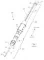
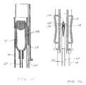
- FIG. 3is a cross sectional view of the safety catheter system of FIG. 2 rotated ninety degrees from the view of FIG. 2 and showing internal details of the insertion mechanism connected to a valved connector which is in turn connected to a catheter for accessing a biological site;
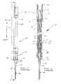
- FIG. 15is a side cross-sectional view of the proximal end of the needle tube showing the connection of the control handle with a flashback chamber attached to the sharp needle;
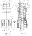
- FIGS. 18 and 19are respectively a full, side, elevation view and a cross-sectional view of an alternate safety catheter connector/catheter device showing the valved connector and the flexible catheter permanently mounted together;
- FIGS. 20 and 21are cross-sectional views of a positive bolus valved connector usable with the safety catheter system in accordance with an alternate embodiment.
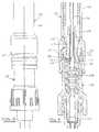
- the connector 38 shown in this embodimentis the ALARIS Medical
- the marquise-shaped bore 92is oriented such that its major axis 94 is perpendicular to the major axis 96 of the elliptically-shaped piston head 88 .
- This geometryassists in naturally biasing the marquise-shaped bore 92 into its naturally open position.
- the naturally open marquise shape of the bore 92creates an outward force parallel to the major axis 96 of the elliptical shaped piston head 88 and an inward force parallel to the minor axis 94 .
- the dimensions of the elliptical piston head 88 and the marquise-shaped bore 92are selected such that when the head is constrained into the circular interior of the ISO Luer taper section 102 of the female luer adapter 74 (see FIG. 5 ), the bore 92 is completely collapsed and tightly closed off from flow.
- the tapered shoulder 104 of the taper lock section 90contacts the ramp/lock section 106 of the female Luer adapter 74 and prevents the top of the piston head 88 from extending beyond the connection port proximal surface 108 to make it substantially flush.
- the internal diameter of the center section 110 of the Luer adapter 74is selected such that, when the piston head 88 is positioned therein (shown in FIG. 9 ), the piston head is free to resume its elliptical shape. This in turn allows the bore 92 to resume its naturally open marquise-shape thereby opening a fluid path through the piston element 80 and the connector 38 .
- the insertion mechanism 34Prior to use the insertion mechanism 34 is initially in its unaccessed state or closed position as shown in FIGS. 2 and 3 .
- the compressible section 66is pre-loaded and causes the piston head 64 to be biased into the ISO Luer taper section 54 of the female Luer adapter 74 of the connector.
- the shoulder 104 of the taper-lock section 90contacts the tapered ramp/lock section 106 of the adapter 74 and prevents the top of the piston head 88 from extending beyond the connection port proximal surface 108 to form a smooth and flush surface.
- the bore 92 throughout the piston head 88is tightly squeezed shut by virtue of the normally elliptically shaped piston head being constrained into the circular cross-section of the ISO Luer taper section 54 .
- the insertion mechanism 34is shown in the initial position with the control handle 58 located near the proximal end 66 of the insertion mechanism.
- the control handleis then grasped by the clinician, such as with a thumb and forefinger, and is slid carefully in the distal direction.
- the flashback chamber 72contacts the blunt cannula control tube 64 as shown in FIG. 11 causing it to also move in the distal direction until its locking tabs 70 engage the locking slots 68 in the wall of the needle tube 48 .
- the position of the control handle at this occurrenceis shown in FIG. 10 .
- the blunt cannula control tubethen no longer interferes with the flashback chamber and the flashback chamber 72 /sharp needle 50 can be extended farther.
- the protecting action of the blunt cannula 62can be clearly seen.
- the blunt cannulaextends from the needle tube 48 into the female port 56 of the female Luer adapter 46 of the connector 38 .
- the piston head 88 of the piston element 80By pressing the piston head 88 of the piston element 80 into the larger diameter center section 110 of the connector, the naturally open, marquise-shaped bore 92 of the piston is permitted to resume its naturally open shape.
- the blunt cannula 62is small enough to fit within the bore 92 thereby providing protection to the piston head from possible tearing or puncture that might be inflicted by the sharp needle 50 if it were not housed within the blunt cannula.
- the sharp needle 50moves with the blunt cannula 62 into the piston head, as can be seen in FIG. 9 .
- the locking tabs 70 of the blunt cannula control tube 64protrude into the locking slots 68 of the wall of the needle tube 59 preventing further extension of the blunt cannula into the connector 38 .
- FIGS. 15 and 16An exemplary locking mechanism is shown in FIGS. 15 and 16 .
- FIG. 15shows the connection between the control handle 58 and the flashback chamber 72 .
- a connection arm 116provides a rigid connection between the control handle 58 and the flashback chamber 72 , which in turn is connected to the sharp needle 50 . Therefore, movement of the control handle will cause movement of the sharp needle. Conversely, securing the control handle in a fixed position will prevent movement of the sharp needle.
- a control handle locking deviceis provided to retain the sharp needle 50 within the needle tube 48 once it has been retracted. As is seen in FIG. 1 , a pair of locking arms 118 face each other, yet are spaced apart. A locking notch 120 provides for movement in the proximal direction from the locking arms. Referring now to FIG.
- the blunt cannula 62When the control handle 58 has been retracted to the position shown in FIG. 17 , the blunt cannula 62 will remain extended. As the needle tube 48 is unthreaded from the connector, movement of the blunt cannula in the proximal direction will permit the spring 86 of the connector to force the piston head 88 once again into the smaller size female Luer port 76 causing the marquise-shaped bore 92 to close, preventing blood from flowing from the catheter out of the connector 38 . A site is now available through the connector 38 to the patient's circulatory system.
- a one way filter or valvemay be included with the flashback chamber 72 so that blood remains in the chamber when the insertion mechanism is removed from the connector 38 , as shown in FIG. 17 .
- the catheter 36is shown permanently attached to the distal port 44 of the connector 38 . This reduces the number of components by combining the catheter hub with the connector housing 38 . Another variation if shown in FIGS.
Landscapes
- Health & Medical Sciences (AREA)
- Heart & Thoracic Surgery (AREA)
- Life Sciences & Earth Sciences (AREA)
- Biomedical Technology (AREA)
- Engineering & Computer Science (AREA)
- Anesthesiology (AREA)
- Pulmonology (AREA)
- Hematology (AREA)
- Animal Behavior & Ethology (AREA)
- General Health & Medical Sciences (AREA)
- Public Health (AREA)
- Veterinary Medicine (AREA)
- Biophysics (AREA)
- Infusion, Injection, And Reservoir Apparatuses (AREA)
- Media Introduction/Drainage Providing Device (AREA)
Abstract
Description
Claims (11)
Priority Applications (3)
| Application Number | Priority Date | Filing Date | Title |
|---|---|---|---|
| US13/225,229US8740850B2 (en) | 2002-12-30 | 2011-09-02 | Safety catheter system and method |
| US14/295,197US9707378B2 (en) | 2002-12-30 | 2014-06-03 | Safety catheter system and method |
| US15/650,660US10881834B2 (en) | 2002-12-30 | 2017-07-14 | Safety catheter system and method |
Applications Claiming Priority (3)
| Application Number | Priority Date | Filing Date | Title |
|---|---|---|---|
| US10/334,125US7125396B2 (en) | 2002-12-30 | 2002-12-30 | Safety catheter system and method |
| US11/585,434US8029472B2 (en) | 2002-12-30 | 2006-10-23 | Safety catheter system and method |
| US13/225,229US8740850B2 (en) | 2002-12-30 | 2011-09-02 | Safety catheter system and method |
Related Parent Applications (1)
| Application Number | Title | Priority Date | Filing Date |
|---|---|---|---|
| US11/585,434ContinuationUS8029472B2 (en) | 2002-12-30 | 2006-10-23 | Safety catheter system and method |
Related Child Applications (1)
| Application Number | Title | Priority Date | Filing Date |
|---|---|---|---|
| US14/295,197ContinuationUS9707378B2 (en) | 2002-12-30 | 2014-06-03 | Safety catheter system and method |
Publications (2)
| Publication Number | Publication Date |
|---|---|
| US20110319827A1 US20110319827A1 (en) | 2011-12-29 |
| US8740850B2true US8740850B2 (en) | 2014-06-03 |
Family
ID=32654939
Family Applications (5)
| Application Number | Title | Priority Date | Filing Date |
|---|---|---|---|
| US10/334,125Expired - LifetimeUS7125396B2 (en) | 2002-12-30 | 2002-12-30 | Safety catheter system and method |
| US11/585,434Expired - LifetimeUS8029472B2 (en) | 2002-12-30 | 2006-10-23 | Safety catheter system and method |
| US13/225,229Expired - LifetimeUS8740850B2 (en) | 2002-12-30 | 2011-09-02 | Safety catheter system and method |
| US14/295,197Expired - Fee RelatedUS9707378B2 (en) | 2002-12-30 | 2014-06-03 | Safety catheter system and method |
| US15/650,660Expired - Fee RelatedUS10881834B2 (en) | 2002-12-30 | 2017-07-14 | Safety catheter system and method |
Family Applications Before (2)
| Application Number | Title | Priority Date | Filing Date |
|---|---|---|---|
| US10/334,125Expired - LifetimeUS7125396B2 (en) | 2002-12-30 | 2002-12-30 | Safety catheter system and method |
| US11/585,434Expired - LifetimeUS8029472B2 (en) | 2002-12-30 | 2006-10-23 | Safety catheter system and method |
Family Applications After (2)
| Application Number | Title | Priority Date | Filing Date |
|---|---|---|---|
| US14/295,197Expired - Fee RelatedUS9707378B2 (en) | 2002-12-30 | 2014-06-03 | Safety catheter system and method |
| US15/650,660Expired - Fee RelatedUS10881834B2 (en) | 2002-12-30 | 2017-07-14 | Safety catheter system and method |
Country Status (8)
| Country | Link |
|---|---|
| US (5) | US7125396B2 (en) |
| EP (1) | EP1581296B1 (en) |
| JP (1) | JP4870927B2 (en) |
| AU (1) | AU2003299981B2 (en) |
| CA (1) | CA2510586C (en) |
| ES (1) | ES2637772T3 (en) |
| NZ (1) | NZ540915A (en) |
| WO (1) | WO2004060466A1 (en) |
Cited By (6)
| Publication number | Priority date | Publication date | Assignee | Title |
|---|---|---|---|---|
| USD808013S1 (en) | 2016-10-27 | 2018-01-16 | Smiths Medical Asd, Inc. | Catheter |
| US10675440B2 (en) | 2016-02-18 | 2020-06-09 | Smiths Medical Asd, Inc. | Closed system catheter |
| US11071849B2 (en) | 2015-08-18 | 2021-07-27 | B. Braun Melsungen Ag | Catheter devices with valves and related methods |
| US11389624B2 (en) | 2020-11-26 | 2022-07-19 | Avia Vascular, Llc | Blood collection devices, systems, and methods |
| US11850377B2 (en) | 2018-12-17 | 2023-12-26 | B. Braun Melsungen Ag | Catheter assemblies and related methods |
| US12048541B2 (en) | 2018-06-08 | 2024-07-30 | Smiths Medical Asd, Inc. | Blood sequestration device and method |
Families Citing this family (183)
| Publication number | Priority date | Publication date | Assignee | Title |
|---|---|---|---|---|
| US6695817B1 (en) | 2000-07-11 | 2004-02-24 | Icu Medical, Inc. | Medical valve with positive flow characteristics |
| US20030010718A1 (en)* | 2001-07-12 | 2003-01-16 | Nxstage Medical, Inc. | Hemodilution cap and methods of use in blood-processing procedures |
| WO2003018104A2 (en) | 2001-08-22 | 2003-03-06 | Nypro, Inc. | Medical valve with expandable seal member |
| US7837658B2 (en) | 2001-11-13 | 2010-11-23 | Nypro Inc. | Anti-drawback medical valve |
| WO2003063934A1 (en)* | 2002-01-28 | 2003-08-07 | Sez Corp. | Safety syringe |
| US8083804B2 (en)* | 2002-06-19 | 2011-12-27 | Tyco Healthcare Group Lp | Method and apparatus for anastomosis including annular joining member |
| DE20210394U1 (en) | 2002-07-04 | 2002-09-12 | B. Braun Melsungen Ag, 34212 Melsungen | catheter introducer |
| US7357792B2 (en) | 2002-10-29 | 2008-04-15 | Nypro Inc. | Positive push medical valve with internal seal |
| US7625346B2 (en)* | 2003-05-30 | 2009-12-01 | Boston Scientific Scimed, Inc. | Transbronchial needle aspiration device |
| US7914502B2 (en) | 2003-07-31 | 2011-03-29 | Nypro Inc. | Anti-drawback medical valve |
| HK1077154A2 (en) | 2003-12-30 | 2006-02-03 | Icu Medical, Inc. | Valve assembly |
| US7331613B2 (en)* | 2004-05-13 | 2008-02-19 | Medtronic, Inc. | Medical tubing connector assembly incorporating strain relief sleeve |
| US20100096311A1 (en)* | 2004-10-28 | 2010-04-22 | Nxstage Medical, Inc | Blood treatment dialyzer/filter design to trap entrained air in a fluid circuit |
| US20060161115A1 (en) | 2004-11-05 | 2006-07-20 | Fangrow Thomas F | Soft-grip medical connector |
| US7537245B2 (en) | 2005-02-14 | 2009-05-26 | Medtronic, Inc. | Strain relief device and connector assemblies incorporating same |
| WO2006127123A2 (en) | 2005-05-20 | 2006-11-30 | Medtronic, Inc. | Locking catheter connector and method |
| US7387624B2 (en)* | 2005-05-20 | 2008-06-17 | Medtronic, Inc. | Squeeze-actuated catheter connecter and method |
| US20070088293A1 (en)* | 2005-07-06 | 2007-04-19 | Fangrow Thomas F Jr | Medical connector with closeable male luer |
| EP1907042B1 (en) | 2005-07-06 | 2009-03-11 | Vascular Pathways Inc. | Intravenous catheter insertion device and method of use |
| US7998134B2 (en) | 2007-05-16 | 2011-08-16 | Icu Medical, Inc. | Medical connector |
| US7753877B2 (en) | 2005-08-08 | 2010-07-13 | Smiths Medical Asd, Inc. | Needle guard strut wall clip |
| DE102005049659B3 (en)* | 2005-10-18 | 2007-04-05 | Autoliv Development Ab | Tightening device for safety belt system in motor vehicle has piston, which is formed in form of olive, with radius in longitudinal direction of pipe is larger than effective radius in transverse direction of pipe |
| CA2626829C (en)* | 2005-10-20 | 2017-01-03 | Frank M. Richmond | Conversion device |
| US7658725B2 (en)* | 2006-02-16 | 2010-02-09 | Smiths Medical Asd, Inc. | Enclosed needle device with duckbill release mechanism |
| US20070191777A1 (en)* | 2006-02-16 | 2007-08-16 | Medex, Inc. | Enclosed Needle Device with Fluid Path Access |
| US7857284B2 (en) | 2006-04-11 | 2010-12-28 | Nypro Inc. | Medical valve with movable member |
| US8308691B2 (en) | 2006-11-03 | 2012-11-13 | B. Braun Melsungen Ag | Catheter assembly and components thereof |
| JP4994775B2 (en) | 2006-10-12 | 2012-08-08 | 日本コヴィディエン株式会社 | Needle point protector |
| BRPI0717401A2 (en) | 2006-10-25 | 2013-11-12 | Icu Medical Inc | CONNECTOR FOR MEDICAL USE |
| US7988674B2 (en) | 2006-10-30 | 2011-08-02 | Medtronic, Inc. | Externally releasable body portal anchors and systems |
| JP4909097B2 (en)* | 2007-01-17 | 2012-04-04 | 日本コヴィディエン株式会社 | Indwelling needle |
| US7922696B2 (en) | 2007-01-24 | 2011-04-12 | Access Scientific, Inc. | Access device |
| US8066717B2 (en)* | 2007-03-19 | 2011-11-29 | Restoration Robotics, Inc. | Device and method for harvesting and implanting follicular units |
| EP3093038B1 (en) | 2007-04-18 | 2019-05-22 | Access Scientific, Inc. | Access device |
| EP2150304B1 (en) | 2007-05-07 | 2010-12-01 | Vascular Pathways Inc. | Intravenous catheter insertion and blood sample devices and method of use |
| US7736342B2 (en)* | 2007-05-30 | 2010-06-15 | Smiths Medical Asd, Inc. | Enclosed needle cannula device with proximal end cap |
| US8784654B2 (en)* | 2007-11-14 | 2014-07-22 | Bayer Medical Care, Inc. | Methods and systems for biological sample collection and analysis |
| US9248240B2 (en)* | 2008-10-14 | 2016-02-02 | Astrazeneca Pharmaceuticals Lp | Formulation delivery device |
| US8202253B1 (en) | 2008-10-17 | 2012-06-19 | Wexler Toby J | Method and apparatus for introducing an intravenous catheter |
| US9078992B2 (en) | 2008-10-27 | 2015-07-14 | Pursuit Vascular, Inc. | Medical device for applying antimicrobial to proximal end of catheter |
| US8679090B2 (en) | 2008-12-19 | 2014-03-25 | Icu Medical, Inc. | Medical connector with closeable luer connector |
| US9168366B2 (en) | 2008-12-19 | 2015-10-27 | Icu Medical, Inc. | Medical connector with closeable luer connector |
| US8454579B2 (en) | 2009-03-25 | 2013-06-04 | Icu Medical, Inc. | Medical connector with automatic valves and volume regulator |
| WO2010117791A1 (en)* | 2009-03-30 | 2010-10-14 | Np Medical Inc. | Medical valve with distal seal actuator |
| JP5836939B2 (en) | 2009-06-22 | 2015-12-24 | エヌピー メディカル インコーポレイテッド | Medical valve with improved back pressure seal |
| US8216187B2 (en)* | 2009-06-29 | 2012-07-10 | Millaghi Medical, Inc. | Safety catheter |
| US8216188B2 (en) | 2009-06-29 | 2012-07-10 | Don Millerd | Safety catheter |
| IL201323A0 (en) | 2009-10-01 | 2010-05-31 | Medimop Medical Projects Ltd | Fluid transfer device for assembling a vial with pre-attached female connector |
| DE102009052962A1 (en) | 2009-11-12 | 2011-06-01 | B. Braun Melsungen Ag | catheter introducer |
| IL202070A0 (en) | 2009-11-12 | 2010-06-16 | Medimop Medical Projects Ltd | Inline liquid drug medical device |
| IL202069A0 (en) | 2009-11-12 | 2010-06-16 | Medimop Medical Projects Ltd | Fluid transfer device with sealing arrangement |
| DK2512398T3 (en) | 2010-02-24 | 2014-10-13 | Medimop Medical Projects Ltd | Liquid drug transfer device with vented ampoule adapter |
| DK2512399T3 (en) | 2010-02-24 | 2015-06-22 | Medimop Medical Projects Ltd | Fluid transfer device with vent arrangement |
| USD644731S1 (en) | 2010-03-23 | 2011-09-06 | Icu Medical, Inc. | Medical connector |
| EP2550058B1 (en) | 2010-05-06 | 2014-03-26 | ICU Medical, Inc. | Medical connector with closeable luer connector |
| US8932258B2 (en) | 2010-05-14 | 2015-01-13 | C. R. Bard, Inc. | Catheter placement device and method |
| US9950139B2 (en) | 2010-05-14 | 2018-04-24 | C. R. Bard, Inc. | Catheter placement device including guidewire and catheter control elements |
| US9872971B2 (en) | 2010-05-14 | 2018-01-23 | C. R. Bard, Inc. | Guidewire extension system for a catheter placement device |
| US11925779B2 (en) | 2010-05-14 | 2024-03-12 | C. R. Bard, Inc. | Catheter insertion device including top-mounted advancement components |
| US10384039B2 (en) | 2010-05-14 | 2019-08-20 | C. R. Bard, Inc. | Catheter insertion device including top-mounted advancement components |
| US8758306B2 (en) | 2010-05-17 | 2014-06-24 | Icu Medical, Inc. | Medical connectors and methods of use |
| US9138572B2 (en) | 2010-06-24 | 2015-09-22 | Np Medical Inc. | Medical valve with fluid volume alteration |
| US9028425B2 (en)* | 2010-07-15 | 2015-05-12 | Becton, Dickinson And Company | Vented blood sampling device |
| IL209290A0 (en) | 2010-11-14 | 2011-01-31 | Medimop Medical Projects Ltd | Inline liquid drug medical device having rotary flow control member |
| EP2670469A4 (en)* | 2011-01-31 | 2017-10-25 | Robert E. Helm, Jr. | Snap-seal sterile intravascular catheter-dressing system |
| US8690833B2 (en) | 2011-01-31 | 2014-04-08 | Vascular Pathways, Inc. | Intravenous catheter and insertion device with reduced blood spatter |
| ES2835652T3 (en) | 2011-02-25 | 2021-06-22 | Bard Inc C R | Medical component insertion device including a retractable needle |
| IL212420A0 (en) | 2011-04-17 | 2011-06-30 | Medimop Medical Projects Ltd | Liquid drug transfer assembly |
| ES2662356T3 (en) | 2011-04-27 | 2018-04-06 | Kpr U.S., Llc | Safety IV catheter assemblies |
| USD903101S1 (en) | 2011-05-13 | 2020-11-24 | C. R. Bard, Inc. | Catheter |
| WO2012162259A2 (en) | 2011-05-20 | 2012-11-29 | Excelsior Medical Corporation | Caps for cannula access devices |
| WO2013009998A2 (en) | 2011-07-12 | 2013-01-17 | Pursuit Vascular, Inc. | Device for delivery of antimicrobial agent into trans-dermal catheter |
| US11173244B2 (en) | 2011-09-02 | 2021-11-16 | Unl Holdings Llc | Drive mechanism for drug delivery pumps with integrated status indication |
| US9707335B2 (en) | 2011-09-02 | 2017-07-18 | Unitract Syringe Pty Ltd | Drive mechanism for drug delivery pumps with integrated status indication |
| CA2845379C (en) | 2011-09-02 | 2019-08-06 | Unitract Syringe Pty Ltd | Insertion mechanism for a drug delivery pump |
| EP2731641B1 (en) | 2011-09-02 | 2021-09-29 | UNL Holdings LLC | Drive mechanism for drug delivery pumps with integrated status indication |
| US9814832B2 (en) | 2011-09-02 | 2017-11-14 | Unl Holdings Llc | Drive mechanism for drug delivery pumps with integrated status indication |
| ES2664517T3 (en) | 2011-09-09 | 2018-04-19 | Icu Medical, Inc. | Medical connectors with fluid resistant coupling interfaces |
| ES2566179T5 (en) | 2011-09-13 | 2019-11-14 | Unitract Syringe Pty Ltd | Connection of sterile fluid passage to medication containers for medication release pumps |
| EP2760521B1 (en) | 2011-09-26 | 2016-01-06 | Covidien LP | Safety iv catheter and needle assembly |
| WO2013048975A1 (en) | 2011-09-26 | 2013-04-04 | Covidien Lp | Safety catheter |
| IL215699A0 (en) | 2011-10-11 | 2011-12-29 | Medimop Medical Projects Ltd | Liquid drug reconstitution assemblage for use with iv bag and drug vial |
| US8834422B2 (en) | 2011-10-14 | 2014-09-16 | Covidien Lp | Vascular access assembly and safety device |
| ES2686114T3 (en)* | 2011-12-20 | 2018-10-16 | Angioclinic Ag | Hyaluronic acid and its use for the treatment of venous insufficiency and varicose veins |
| USD737436S1 (en) | 2012-02-13 | 2015-08-25 | Medimop Medical Projects Ltd. | Liquid drug reconstitution assembly |
| USD720451S1 (en) | 2012-02-13 | 2014-12-30 | Medimop Medical Projects Ltd. | Liquid drug transfer assembly |
| KR20140135736A (en) | 2012-03-12 | 2014-11-26 | 유니트랙트 시린지 피티와이 엘티디 | Fill-finish cartridges for sterile fluid pathway assemblies and drug delivery devices incorporating fill-finish cartridges |
| IL219065A0 (en) | 2012-04-05 | 2012-07-31 | Medimop Medical Projects Ltd | Fluid transfer device with manual operated cartridge release arrangement |
| US8622967B2 (en)* | 2012-05-15 | 2014-01-07 | Becton, Dickinson And Company | Over-the-needle intravenous catheter assembly with integrated intravenous tubing |
| IL221635A0 (en) | 2012-08-26 | 2012-12-31 | Medimop Medical Projects Ltd | Drug vial mixing and transfer device for use with iv bag and drug vial |
| IL221634A0 (en) | 2012-08-26 | 2012-12-31 | Medimop Medical Projects Ltd | Universal drug vial adapter |
| ES2637229T3 (en) | 2012-08-29 | 2017-10-11 | Unitract Syringe Pty Ltd | Controlled drive mechanisms for medication delivery pumps |
| USD745142S1 (en) | 2012-08-30 | 2015-12-08 | Unitract Syringe Pty Ltd | Drug delivery pump |
| DK2872100T3 (en) | 2012-09-13 | 2017-07-10 | Medimop Medical Projects Ltd | Telescopic female adapter for drug ampoule |
| EP2916905A4 (en) | 2012-11-12 | 2016-11-09 | Icu Medical Inc | MEDICAL CONNECTION |
| USD734868S1 (en) | 2012-11-27 | 2015-07-21 | Medimop Medical Projects Ltd. | Drug vial adapter with downwardly depending stopper |
| US10426932B2 (en) | 2013-01-17 | 2019-10-01 | Toby Wexler | Method and apparatus for introducing an intravenous catheter |
| US9802030B2 (en) | 2013-01-25 | 2017-10-31 | Unl Holdings Llc | Integrated sliding seal fluid pathway connection and drug containers for drug delivery pumps |
| USD723157S1 (en) | 2013-03-12 | 2015-02-24 | Unitract Syringe Pty Ltd | Drug delivery pump |
| WO2014119986A1 (en)* | 2013-01-30 | 2014-08-07 | Equipos Médicos Vizcarra, S.A. | Peripheral intravenous catheter with bellows-type passive safety system ivcbts |
| WO2014120741A1 (en) | 2013-01-30 | 2014-08-07 | Vascular Pathways, Inc. | Systems and methods for venipuncture and catheter placement |
| IL225734A0 (en) | 2013-04-14 | 2013-09-30 | Medimop Medical Projects Ltd | Ready-to-use drug vial assemblages including drug vial and drug vial closure having fluid transfer member, and drug vial closure therefor |
| CN105228676B (en) | 2013-05-10 | 2018-01-05 | 麦迪麦珀医疗工程有限公司 | Include the medical treatment device of the vial adapter with inline dry kit |
| US9415199B2 (en)* | 2013-06-14 | 2016-08-16 | Skill Partner Limited | Leak proof needleless medical connector |
| US20140378914A1 (en)* | 2013-06-24 | 2014-12-25 | Ziad Hassan Abu Ayyash | Cannula Apparatus |
| USD767124S1 (en) | 2013-08-07 | 2016-09-20 | Medimop Medical Projects Ltd. | Liquid transfer device with integral vial adapter |
| USD765837S1 (en) | 2013-08-07 | 2016-09-06 | Medimop Medical Projects Ltd. | Liquid transfer device with integral vial adapter |
| DE212014000169U1 (en) | 2013-08-07 | 2016-03-14 | Medimop Medical Projects Ltd. | Fluid transfer devices for use with infusion fluid containers |
| AU2014308659B2 (en) | 2013-08-23 | 2018-11-01 | Unl Holdings Llc | Integrated pierceable seal fluid pathway connection and drug containers for drug delivery pumps |
| US9456775B2 (en) | 2013-09-06 | 2016-10-04 | Millaghi Medical, Inc. | Passive safety I.V. blood collection catheter |
| AU2014364218B2 (en) | 2013-12-11 | 2019-06-06 | Icu Medical, Inc. | Check valve |
| CA2939929C (en) | 2014-02-28 | 2023-04-11 | Sentreheart, Inc. | Pericardial access devices and methods |
| EP3137122B1 (en) | 2014-05-02 | 2019-09-04 | Excelsior Medical Corporation | Strip package for antiseptic cap |
| WO2016037127A1 (en) | 2014-09-05 | 2016-03-10 | C.R. Bard, Inc. | Catheter insertion device including retractable needle |
| USD757933S1 (en) | 2014-09-11 | 2016-05-31 | Medimop Medical Projects Ltd. | Dual vial adapter assemblage |
| EP3200851A1 (en) | 2014-09-29 | 2017-08-09 | Unitract Syringe Pty Ltd | Rigid needle insertion mechanism for a drug delivery pump |
| TWD174176S (en) | 2014-11-07 | 2016-03-01 | 優尼翠克注射器有限公司 | Portion of drug delivery device (2) |
| USD793551S1 (en) | 2014-12-03 | 2017-08-01 | Icu Medical, Inc. | Fluid manifold |
| USD786427S1 (en) | 2014-12-03 | 2017-05-09 | Icu Medical, Inc. | Fluid manifold |
| JP6358724B2 (en) | 2015-01-05 | 2018-07-18 | ウエスト・ファーマ.サービシーズ・イスラエル,リミテッド | Dual vial adapter assembly with easy removable pill adapter to ensure accurate use |
| US20160220805A1 (en) | 2015-01-30 | 2016-08-04 | Smiths Medical Asd, Inc. | Intravenous catheter assembly design |
| WO2016123620A1 (en) | 2015-01-30 | 2016-08-04 | Smiths Medical Asd, Inc. | Needle assembly with diagnostic analysis provisions |
| USD903100S1 (en) | 2015-05-01 | 2020-11-24 | C. R. Bard, Inc. | Catheter placement device |
| DK3294404T3 (en) | 2015-05-08 | 2025-09-08 | Icu Medical Inc | MEDICAL CONNECTORS CONFIGURED TO RECEIVE EMISSIONS OF THERAPEUTIC AGENTS |
| CN104799915B (en)* | 2015-05-11 | 2017-04-05 | 南京微创医学科技股份有限公司 | A kind of ultrasonic pin |
| CN113350614A (en) | 2015-05-15 | 2021-09-07 | C·R·巴德股份有限公司 | Catheter placement device including extendable needle safety feature |
| USD794770S1 (en) | 2015-06-26 | 2017-08-15 | Unitract Syringe Pty Ltd | Drug delivery pump |
| USD794771S1 (en) | 2015-07-10 | 2017-08-15 | Unitract Syringe Pty Ltd. | Drug delivery pump |
| WO2017009822A1 (en) | 2015-07-16 | 2017-01-19 | Medimop Medical Projects Ltd | Liquid drug transfer devices for secure telescopic snap fit on injection vials |
| US10039913B2 (en) | 2015-07-30 | 2018-08-07 | Carefusion 303, Inc. | Tamper-resistant cap |
| USD779662S1 (en)* | 2015-08-07 | 2017-02-21 | Laborie Medical Technologies, Corp. | Female catheter connector |
| CA2998359C (en)* | 2015-09-18 | 2024-02-06 | Becton, Dickinson And Company | Safety iv catheter with molded-open blood control valve |
| US10195415B2 (en) | 2015-09-21 | 2019-02-05 | Carefusion 303, Inc. | Priming device |
| USD801522S1 (en) | 2015-11-09 | 2017-10-31 | Medimop Medical Projects Ltd. | Fluid transfer assembly |
| CN115721558A (en) | 2015-11-25 | 2023-03-03 | 西部制药服务以色列有限公司 | Dual vial adapter assembly comprising a drug vial adapter having a self-sealing inlet valve |
| JP6927667B2 (en)* | 2016-03-08 | 2021-09-01 | ニプロ株式会社 | Enteral nutrition connector |
| CN105997201B (en)* | 2016-05-04 | 2020-06-26 | 冯军峰 | paracentesis catheter |
| IL245800A0 (en) | 2016-05-24 | 2016-08-31 | West Pharma Services Il Ltd | Dual vial adapter assemblages including identical twin vial adapters |
| IL245803A0 (en) | 2016-05-24 | 2016-08-31 | West Pharma Services Il Ltd | Dual vial adapter assemblages including vented drug vial adapter and vented liquid vial adapter |
| IL246073A0 (en) | 2016-06-06 | 2016-08-31 | West Pharma Services Il Ltd | Fluid transfer devices for use with drug pump cartridge having slidable driving plunger |
| IL264404B (en) | 2016-08-08 | 2022-07-01 | Unitract Syringe Pty Ltd | Drug delivery device and method for connecting a fluid flow path |
| IL247376A0 (en) | 2016-08-21 | 2016-12-29 | Medimop Medical Projects Ltd | Syringe assembly |
| US10695487B2 (en) | 2016-08-30 | 2020-06-30 | Unl Holdings Llc | Controlled delivery drive mechanisms for drug delivery pumps |
| US10493262B2 (en) | 2016-09-12 | 2019-12-03 | C. R. Bard, Inc. | Blood control for a catheter insertion device |
| PT3525865T (en) | 2016-10-14 | 2022-11-17 | Icu Medical Inc | Sanitizing caps for medical connectors |
| USD832430S1 (en) | 2016-11-15 | 2018-10-30 | West Pharma. Services IL, Ltd. | Dual vial adapter assemblage |
| IL249408A0 (en) | 2016-12-06 | 2017-03-30 | Medimop Medical Projects Ltd | Liquid transfer device for use with infusion liquid container and pincers-like hand tool for use therewith for releasing intact drug vial therefrom |
| EP3585471B1 (en) | 2017-03-01 | 2025-01-01 | C. R. Bard, Inc. | Catheter insertion device |
| IL251458A0 (en) | 2017-03-29 | 2017-06-29 | Medimop Medical Projects Ltd | User actuated liquid drug transfer devices for use in ready-to-use (rtu) liquid drug transfer assemblages |
| EP4480525A3 (en) | 2017-04-13 | 2025-04-09 | Teleflex Medical Incorporated | Catheter insertion device |
| WO2018204206A2 (en) | 2017-05-01 | 2018-11-08 | Icu Medical, Inc. | Medical fluid connectors and methods for providing additives in medical fluid lines |
| IL254802A0 (en) | 2017-09-29 | 2017-12-31 | Medimop Medical Projects Ltd | Dual vial adapter assemblages with twin vented female vial adapters |
| ES2980192T3 (en) | 2018-03-07 | 2024-09-30 | Bard Access Systems Inc | Guidewire advancement and blood reflux systems for a medical device insertion system |
| US11571550B2 (en)* | 2018-04-20 | 2023-02-07 | Becton, Dickinson And Company | Catheter system with remote instrument delivery |
| USD903864S1 (en) | 2018-06-20 | 2020-12-01 | West Pharma. Services IL, Ltd. | Medication mixing apparatus |
| JP1630477S (en) | 2018-07-06 | 2019-05-07 | ||
| USD921884S1 (en) | 2018-07-27 | 2021-06-08 | Bard Access Systems, Inc. | Catheter insertion device |
| US11541220B2 (en) | 2018-11-07 | 2023-01-03 | Icu Medical, Inc. | Needleless connector with antimicrobial properties |
| US11400195B2 (en) | 2018-11-07 | 2022-08-02 | Icu Medical, Inc. | Peritoneal dialysis transfer set with antimicrobial properties |
| US11541221B2 (en) | 2018-11-07 | 2023-01-03 | Icu Medical, Inc. | Tubing set with antimicrobial properties |
| US11534595B2 (en) | 2018-11-07 | 2022-12-27 | Icu Medical, Inc. | Device for delivering an antimicrobial composition into an infusion device |
| US11517732B2 (en) | 2018-11-07 | 2022-12-06 | Icu Medical, Inc. | Syringe with antimicrobial properties |
| EP3883638A1 (en) | 2018-11-21 | 2021-09-29 | ICU Medical, Inc. | Antimicrobial device comprising a cap with ring and insert |
| US12246157B2 (en) | 2019-01-14 | 2025-03-11 | Becton, Dickinson And Company | Needleless access connector facilitating instrument delivery to a catheter assembly |
| USD923812S1 (en) | 2019-01-16 | 2021-06-29 | West Pharma. Services IL, Ltd. | Medication mixing apparatus |
| JP1648075S (en) | 2019-01-17 | 2019-12-16 | ||
| JP7209849B2 (en) | 2019-01-18 | 2023-01-20 | ウェスト・ファーマ・サービシーズ・アイエル・リミテッド | Liquid transfer device for use with IV bottles |
| US11918542B2 (en) | 2019-01-31 | 2024-03-05 | West Pharma. Services IL, Ltd. | Liquid transfer device |
| JP7284289B2 (en) | 2019-04-09 | 2023-05-30 | ウェスト ファーマ サービシーズ イスラエル リミテッド | Infusion device with integrated syringe |
| US12350418B2 (en) | 2019-04-12 | 2025-07-08 | Stryker Corporation | Manifold for a medical waste collection system |
| US10471188B1 (en) | 2019-04-12 | 2019-11-12 | Stryker Corporation | Manifold for filtering medical waste being drawn under vacuum into a medical waste collection system |
| CN113966238B (en)* | 2019-04-12 | 2024-09-27 | 史赛克公司 | Manifolds for medical waste collection systems |
| KR20240122586A (en) | 2019-04-30 | 2024-08-12 | 웨스트 파마. 서비시즈 일, 리미티드 | Liquid transfer device with dual lumen iv spike |
| WO2020263824A1 (en)* | 2019-06-26 | 2020-12-30 | Smiths Medical Asd, Inc. | Catheter hub adapted to be used with mutiuse blood control valve |
| CA3151126A1 (en) | 2019-08-19 | 2021-02-25 | Becton, Dickinson And Company | Midline catheter placement device |
| CA3169051A1 (en) | 2019-09-10 | 2021-03-18 | Medsource International Llc | An intravenous catheter device |
| USD956958S1 (en) | 2020-07-13 | 2022-07-05 | West Pharma. Services IL, Ltd. | Liquid transfer device |
| JP7024843B2 (en)* | 2020-10-20 | 2022-02-24 | ニプロ株式会社 | Medical connector |
| AU2021393133A1 (en)* | 2020-12-04 | 2023-06-29 | Tucann Medical Pty Ltd | Over-the-needle intravenous introducer assembly |
| CA3204371A1 (en) | 2020-12-07 | 2022-06-16 | Icu Medical, Inc. | Peritoneal dialysis caps, systems and methods |
| US12337123B2 (en) | 2021-05-06 | 2025-06-24 | Medsource Labs, Llc | Safety intravenous cannula |
| US12186497B2 (en) | 2022-01-14 | 2025-01-07 | Medsource International Llc | Intravenous cannula |
| US20240151339A1 (en)* | 2022-11-08 | 2024-05-09 | Carefusion 303, Inc. | Fluid connector assembly with neutral fluid displacement that limits connector damage |
Citations (5)
| Publication number | Priority date | Publication date | Assignee | Title |
|---|---|---|---|---|
| US4917669A (en)* | 1989-02-08 | 1990-04-17 | Safetyject | Catheter inserter |
| US5562631A (en)* | 1995-06-07 | 1996-10-08 | Johnson & Johnson Medical, Inc. | Catheter arrangement with interlocking sequenced guarding members for protecting cannula |
| US5672160A (en)* | 1995-01-21 | 1997-09-30 | The Boc Group Plc | Medical devices |
| US5725503A (en)* | 1996-08-07 | 1998-03-10 | Aeroquip Corporation | Ratcheting needle protector assembly |
| US6213978B1 (en)* | 1998-10-27 | 2001-04-10 | Cherie A. Voyten | Intravenous catheter insertion apparatus |
Family Cites Families (96)
| Publication number | Priority date | Publication date | Assignee | Title |
|---|---|---|---|---|
| US34223A (en)* | 1862-01-21 | Maerits act ure of abtipicial teeth | ||
| US500740A (en)* | 1893-07-04 | Administratrix of luke | ||
| US4512766A (en)* | 1982-12-08 | 1985-04-23 | Whitman Medical Corporation | Catheter valve |
| US5688254A (en)* | 1983-01-24 | 1997-11-18 | Icu Medical, Inc. | Medical connector |
| GB8618253D0 (en)* | 1986-07-25 | 1986-09-03 | Wallace Ltd H G | Intermittent administration of therapeutic substance |
| US4762516A (en)* | 1987-03-05 | 1988-08-09 | Luther Medical Products, Inc. | Assembly of needle catheter protector |
| US4832696A (en)* | 1987-03-05 | 1989-05-23 | Luther Medical Products, Inc. | Assembly of needle and protector |
| US4828548A (en)* | 1987-03-16 | 1989-05-09 | Walter Gregory W | Safety catheter |
| US4874375A (en)* | 1987-04-13 | 1989-10-17 | Ellison Arthur E | Tissue retractor |
| US4944725A (en)* | 1987-06-01 | 1990-07-31 | Mcdonald Michael | Safety needle apparatus |
| US4834718A (en)* | 1987-06-01 | 1989-05-30 | Michael McDonald | Safety needle apparatus |
| US4850961A (en)* | 1987-07-30 | 1989-07-25 | Wanderer Alan A | Indwelling placement device with guard |
| US5009642A (en)* | 1987-09-28 | 1991-04-23 | Bio-Plexus, Inc. | Self-blunting needle assembly for use with a catheter, and catheter assembly using the same |
| US4950252A (en)* | 1987-11-02 | 1990-08-21 | Luther Medical Products, Inc. | Single hand actuated locking safety catheter and method of use |
| US4846805A (en)* | 1987-12-04 | 1989-07-11 | Icu Medical, Inc. | Catheter insert device |
| US4842591A (en)* | 1988-01-21 | 1989-06-27 | Luther Ronald B | Connector with one-way septum valve, and assembly |
| US5064416A (en)* | 1988-05-26 | 1991-11-12 | Newgard Kent W | Self-occluding intravascular cannula assembly |
| US4944728A (en)* | 1988-10-17 | 1990-07-31 | Safe Medical Devices, Inc. | Intravenous catheter placement device |
| USRE34223E (en)* | 1989-02-08 | 1993-04-13 | Care Medical Devices, Inc. | Catheter inserter |
| US5000740A (en)* | 1989-04-10 | 1991-03-19 | Critikon, Inc. | Catheter with needle guard |
| US5078687A (en)* | 1989-05-17 | 1992-01-07 | Critikon, Inc. | Catheter with backflow restriction |
| US4994042A (en)* | 1989-10-02 | 1991-02-19 | Vadher Dinesh L | Combined catheter and needle |
| US5053014A (en)* | 1990-02-01 | 1991-10-01 | Critikon, Inc. | Catheter with controlled valve |
| US5205829A (en)* | 1990-02-09 | 1993-04-27 | Lituchy Andrew E | Safety disposable intravenous (I.V. assembly) |
| US5019049A (en)* | 1990-02-20 | 1991-05-28 | Haining Michael L | Intravenous catheter and insertion device |
| US5108378A (en)* | 1990-05-09 | 1992-04-28 | Safety Syringes, Inc. | Disposable self-shielding hypodermic syringe |
| US5279581A (en)* | 1990-05-09 | 1994-01-18 | Firth John R | Disposable self-shielding hypodermic syringe |
| US5102394A (en)* | 1990-12-19 | 1992-04-07 | Abbott Laboratories | Catheter assembly with protective shield |
| US5112312A (en)* | 1991-03-14 | 1992-05-12 | Luther Medical Products, Inc. | Vascular/venous access device and method of utilizing and forming the same |
| DE9105229U1 (en)* | 1991-04-27 | 1991-06-13 | B. Braun Melsungen Ag, 3508 Melsungen | Valve device for a catheter |
| FR2677544B1 (en) | 1991-06-14 | 1993-09-24 | Oreal | COSMETIC COMPOSITION CONTAINING A MIXTURE OF NANOPIGMENTS OF METAL OXIDES AND MELANIC PIGMENTS. |
| IT1251532B (en)* | 1991-10-31 | 1995-05-16 | Pasquale Mastronardi | NEEDLE CANNULA PROVIDED WITH SAFETY DEVICE |
| US5312359A (en)* | 1991-12-03 | 1994-05-17 | Wallace Henry G | Intravenous cannula insertion assembly with protective shield |
| US5304136A (en)* | 1992-02-07 | 1994-04-19 | Becton, Dickinson And Company | Needle sheath |
| US5176650A (en)* | 1992-02-10 | 1993-01-05 | Haining Michael L | Intravenous catheter and insertion device |
| US5279590A (en)* | 1992-08-21 | 1994-01-18 | Gesco International, Inc. | Catheter placement apparatus |
| US5215525A (en)* | 1992-09-29 | 1993-06-01 | Sturman Warren M | Safety casing for intravenous catheter needle |
| ES2105330T3 (en)* | 1992-11-24 | 1997-10-16 | Braun Melsungen Ag | CATHETERIZATION INSTRUMENTAL. |
| SE502537C2 (en)* | 1992-11-26 | 1995-11-06 | Boc Ohmeda Ab | Device for infusion cannula |
| CA2127206A1 (en) | 1993-07-23 | 1995-01-24 | Charles W. Daugherty | Self contained needle and shield |
| US5830125A (en)* | 1993-08-12 | 1998-11-03 | Scribner-Browne Medical Design Incorporated | Catheter introducer with suture capability |
| US5419766A (en)* | 1993-09-28 | 1995-05-30 | Critikon, Inc. | Catheter with stick protection |
| GB9323121D0 (en)* | 1993-11-09 | 1994-01-05 | Smiths Industries Plc | Needle protection assemblies |
| CA2135706C (en)* | 1993-11-15 | 1999-06-15 | Walter E. Cover | Retractable-needle cannula insertion set with refinements to better control leakage, retraction speed, and reuse |
| US5830165A (en)* | 1994-01-03 | 1998-11-03 | Rowe; Denis O. | Upper extremity swathe sling apparatus |
| US5456668A (en)* | 1994-01-14 | 1995-10-10 | F. H. Faulding & Co. Limited | Retractable venipuncture catheter needle and receptacle |
| GB9403021D0 (en)* | 1994-02-17 | 1994-04-06 | Clinical Product Dev Ltd | Couplings for medical cannulae |
| US5405323A (en) | 1994-02-22 | 1995-04-11 | Aeroquip Corporation | Catheter check valve assembly |
| US5573510A (en)* | 1994-02-28 | 1996-11-12 | Isaacson; Dennis R. | Safety intravenous catheter assembly with automatically retractable needle |
| US5531701A (en)* | 1994-06-06 | 1996-07-02 | Luther Medical Products, Inc. | Over-the-needle catheter |
| US5531720A (en)* | 1994-07-08 | 1996-07-02 | Atkins; Stephen L. | I.V. starting kit and coupling, and method |
| US5462253A (en)* | 1994-07-22 | 1995-10-31 | General Motors Corporation | Dual slope flow control valve |
| US5584812A (en)* | 1994-12-16 | 1996-12-17 | Stonefield Medical Products, Inc. | Closed intravenous system |
| CA2168615A1 (en)* | 1995-03-07 | 1996-09-08 | Timothy J. Erskine | Catheter-advancement actuated needle retraction system |
| CA2169220A1 (en)* | 1995-03-16 | 1996-09-17 | Greg L. Brimhall | Control forward introducer needle and catheter assembly |
| CA2215507C (en)* | 1995-03-16 | 2001-08-21 | City Of Hope | Intravascular needle with movable safety shield |
| US5688249A (en)* | 1995-03-28 | 1997-11-18 | Johnson & Johnson Medical, Inc. | Telescoping members for catheter introducer assembly |
| US5620427A (en)* | 1995-04-27 | 1997-04-15 | David R. Kipp | Luer lock system |
| NZ286445A (en)* | 1995-05-16 | 1997-12-19 | Ivac Corp | Needleless luer connector: deformable piston occludes bore |
| US5688253A (en)* | 1995-05-31 | 1997-11-18 | Paradis; Joseph R. | Needle locking system |
| US5830189A (en)* | 1995-06-07 | 1998-11-03 | Johnson & Johnson Medical, Inc. | Catheter hub to nose engagement |
| US5685860A (en)* | 1995-06-07 | 1997-11-11 | Johnson & Johnson Medical, Inc. | Self-capping needle assembly |
| US5853393A (en)* | 1995-06-07 | 1998-12-29 | Johnson & Johnson Medical, Inc. | Catheter needle locking and catheter hub unlocking mechanism |
| GB9512531D0 (en)* | 1995-06-20 | 1995-08-23 | Boc Group Plc | Medical devices |
| EP0763369B1 (en)* | 1995-09-18 | 2002-01-09 | Becton, Dickinson and Company | Needle shield with collapsible cover |
| US5843038A (en)* | 1995-10-31 | 1998-12-01 | University Of Southern California | Finder-thinwall needle combination for safely inserting a catheter into a central vein |
| US5651772A (en)* | 1996-02-28 | 1997-07-29 | Aeroquip Corporation | Needle guard assembly |
| US5817069A (en)* | 1996-02-28 | 1998-10-06 | Vadus, Inc. | Valve assembly |
| GB9605206D0 (en)* | 1996-03-12 | 1996-05-15 | Boc Group Plc | Medical devices |
| US5865806A (en)* | 1996-04-04 | 1999-02-02 | Becton Dickinson And Company | One step catheter advancement automatic needle retraction system |
| US5820610A (en)* | 1996-04-30 | 1998-10-13 | Medtronic, Inc. | Microbore catheter with velocity reducing chamber |
| US5824001A (en)* | 1996-06-10 | 1998-10-20 | Becton Dickinson And Company | Radially vented flashback chamber and plug assembly |
| US5830190A (en)* | 1996-06-11 | 1998-11-03 | Becton Dickinson And Company | Protected needle catheter placement device having needle placement visualization features and method for its use |
| US5810785A (en)* | 1996-08-19 | 1998-09-22 | Johnson & Johnson Medical, Inc. | Blown-in-place blood gasket for a safety catheter |
| GB9617502D0 (en)* | 1996-08-21 | 1996-10-02 | Boc Group Plc | Medical devices |
| US5800399A (en)* | 1996-08-27 | 1998-09-01 | Johnson & Johnson Medical, Inc. | Low-cost method of assembling an extruded cannula holder for a catheter insertion device |
| US5683368A (en)* | 1996-09-19 | 1997-11-04 | Johnson & Johnson Medical, Inc. | Controlled motion lock for safety catheter |
| WO1998026835A1 (en) | 1996-12-16 | 1998-06-25 | Icu Medical, Inc. | Positive flow valve |
| US5951520A (en)* | 1996-12-19 | 1999-09-14 | Bio-Plexus, Inc. | Self-blunting needle medical devices and methods of manufacture thereof |
| US5817058A (en)* | 1996-12-23 | 1998-10-06 | Shaw; Thomas J. | Retractable catheter introducer structure |
| US6080137A (en)* | 1997-01-08 | 2000-06-27 | Vadus, Inc. | Needle protector |
| US5954698A (en)* | 1997-01-08 | 1999-09-21 | Vadus, Inc. | Catheter apparatus having valved catheter hub and needle protector |
| US6089541A (en)* | 1998-09-10 | 2000-07-18 | Halkey-Roberts Corporation | Valve having a valve body and a deformable stem therein |
| US6077244A (en)* | 1998-04-30 | 2000-06-20 | Mdc Investment Holdings, Inc. | Catheter insertion device with retractable needle |
| US6056718A (en)* | 1998-03-04 | 2000-05-02 | Minimed Inc. | Medication infusion set |
| US6217556B1 (en)* | 1998-03-19 | 2001-04-17 | Allegiance Corporation | Drainage catheter |
| US5989220A (en)* | 1998-05-26 | 1999-11-23 | Retractable Technologies Inc. | Self-retracting IV catheter introducer |
| US5885252A (en)* | 1998-06-03 | 1999-03-23 | Liu; Wen-Neng | Automatic safety infusion catheter needle |
| US5891098A (en)* | 1998-08-17 | 1999-04-06 | Huang; Robert | Safety intravenous catheter |
| US6050976A (en)* | 1998-12-23 | 2000-04-18 | Specialized Health Products, Inc. | In-line retractable safety catheter needle insertion assembly |
| US6149629A (en)* | 1999-05-14 | 2000-11-21 | Specialized Health Products, Inc. | Medical needle safety apparatus and methods |
| JP2001170187A (en)* | 1999-12-17 | 2001-06-26 | Terumo Corp | Connector |
| US6641564B1 (en)* | 2000-11-06 | 2003-11-04 | Medamicus, Inc. | Safety introducer apparatus and method therefor |
| JP4996015B2 (en)* | 2001-03-12 | 2012-08-08 | メディキット株式会社 | Indwelling catheter |
| US6506181B2 (en)* | 2001-05-25 | 2003-01-14 | Becton, Dickinson And Company | Catheter having a low drag septum |
| AUPR568901A0 (en) | 2001-06-14 | 2001-07-12 | Occupational & Medical Innovations Ltd | A retractable needle assembly for a catheter and which uses an elastomeric member to retract the needle |
- 2002
- 2002-12-30USUS10/334,125patent/US7125396B2/ennot_activeExpired - Lifetime
- 2003
- 2003-12-22AUAU2003299981Apatent/AU2003299981B2/ennot_activeExpired
- 2003-12-22CACA2510586Apatent/CA2510586C/ennot_activeExpired - Lifetime
- 2003-12-22WOPCT/US2003/041390patent/WO2004060466A1/enactiveApplication Filing
- 2003-12-22EPEP03800246.5Apatent/EP1581296B1/ennot_activeExpired - Lifetime
- 2003-12-22ESES03800246.5Tpatent/ES2637772T3/ennot_activeExpired - Lifetime
- 2003-12-22NZNZ540915Apatent/NZ540915A/ennot_activeIP Right Cessation
- 2003-12-22JPJP2004565748Apatent/JP4870927B2/ennot_activeExpired - Lifetime
- 2006
- 2006-10-23USUS11/585,434patent/US8029472B2/ennot_activeExpired - Lifetime
- 2011
- 2011-09-02USUS13/225,229patent/US8740850B2/ennot_activeExpired - Lifetime
- 2014
- 2014-06-03USUS14/295,197patent/US9707378B2/ennot_activeExpired - Fee Related
- 2017
- 2017-07-14USUS15/650,660patent/US10881834B2/ennot_activeExpired - Fee Related
Patent Citations (5)
| Publication number | Priority date | Publication date | Assignee | Title |
|---|---|---|---|---|
| US4917669A (en)* | 1989-02-08 | 1990-04-17 | Safetyject | Catheter inserter |
| US5672160A (en)* | 1995-01-21 | 1997-09-30 | The Boc Group Plc | Medical devices |
| US5562631A (en)* | 1995-06-07 | 1996-10-08 | Johnson & Johnson Medical, Inc. | Catheter arrangement with interlocking sequenced guarding members for protecting cannula |
| US5725503A (en)* | 1996-08-07 | 1998-03-10 | Aeroquip Corporation | Ratcheting needle protector assembly |
| US6213978B1 (en)* | 1998-10-27 | 2001-04-10 | Cherie A. Voyten | Intravenous catheter insertion apparatus |
Cited By (14)
| Publication number | Priority date | Publication date | Assignee | Title |
|---|---|---|---|---|
| US11883614B2 (en) | 2015-08-18 | 2024-01-30 | B. Braun Melsungen Ag | Catheter devices with valves and related methods |
| US11071849B2 (en) | 2015-08-18 | 2021-07-27 | B. Braun Melsungen Ag | Catheter devices with valves and related methods |
| US11141569B2 (en) | 2015-08-18 | 2021-10-12 | B. Braun Melsungen Ag | Catheter devices with valves and related methods |
| US11957850B2 (en) | 2015-08-18 | 2024-04-16 | B. Braun Melsungen Ag | Catheter devices with valves and related methods |
| US11684757B2 (en) | 2015-08-18 | 2023-06-27 | B. Braun Melsungen Ag | Valved catheter assemblies and related methods |
| US10675440B2 (en) | 2016-02-18 | 2020-06-09 | Smiths Medical Asd, Inc. | Closed system catheter |
| US12343482B2 (en) | 2016-02-18 | 2025-07-01 | Icu Medical, Inc. | Closed system catheter |
| USD893711S1 (en) | 2016-10-27 | 2020-08-18 | Smiths Medical Asd, Inc. | Catheter assembly |
| USD808013S1 (en) | 2016-10-27 | 2018-01-16 | Smiths Medical Asd, Inc. | Catheter |
| US12048541B2 (en) | 2018-06-08 | 2024-07-30 | Smiths Medical Asd, Inc. | Blood sequestration device and method |
| US11850377B2 (en) | 2018-12-17 | 2023-12-26 | B. Braun Melsungen Ag | Catheter assemblies and related methods |
| US11638806B2 (en) | 2020-11-26 | 2023-05-02 | Avia Vascular, Llc | Blood collection devices, systems, and methods |
| US11452847B1 (en) | 2020-11-26 | 2022-09-27 | Avia Vascular, Llc | Blood collection devices, systems, and methods |
| US11389624B2 (en) | 2020-11-26 | 2022-07-19 | Avia Vascular, Llc | Blood collection devices, systems, and methods |
Also Published As
| Publication number | Publication date |
|---|---|
| WO2004060466A1 (en) | 2004-07-22 |
| US8029472B2 (en) | 2011-10-04 |
| EP1581296B1 (en) | 2017-05-24 |
| ES2637772T3 (en) | 2017-10-17 |
| US7125396B2 (en) | 2006-10-24 |
| CA2510586A1 (en) | 2004-07-22 |
| JP2006512166A (en) | 2006-04-13 |
| US20070100284A1 (en) | 2007-05-03 |
| JP4870927B2 (en) | 2012-02-08 |
| US20040127854A1 (en) | 2004-07-01 |
| NZ540915A (en) | 2007-11-30 |
| CA2510586C (en) | 2012-01-31 |
| AU2003299981A1 (en) | 2004-07-29 |
| US20140288500A1 (en) | 2014-09-25 |
| AU2003299981B2 (en) | 2009-07-02 |
| US20110319827A1 (en) | 2011-12-29 |
| US9707378B2 (en) | 2017-07-18 |
| US20170368315A1 (en) | 2017-12-28 |
| US10881834B2 (en) | 2021-01-05 |
| EP1581296A1 (en) | 2005-10-05 |
Similar Documents
| Publication | Publication Date | Title |
|---|---|---|
| US10881834B2 (en) | Safety catheter system and method | |
| US12343482B2 (en) | Closed system catheter | |
| US12318559B2 (en) | Ported IV catheter having external needle shield and internal blood control septum | |
| US6213978B1 (en) | Intravenous catheter insertion apparatus | |
| JP2023133444A (en) | Releasable safety catheter insertion assembly | |
| US20040181192A1 (en) | Vascular access device and method of using same | |
| EP3773856B1 (en) | Iv catheter with a tip protector | |
| EP3651845A1 (en) | Methods and devices for vascular access | |
| US20250152918A1 (en) | Closed system catheter | |
| KR20220159999A (en) | pediatric catheter system | |
| CN118541189A (en) | Intravenous cannula | |
| US20120101454A1 (en) | Splash free needle assembly |
Legal Events
| Date | Code | Title | Description |
|---|---|---|---|
| AS | Assignment | Owner name:CAREFUSION 303, INC., CALIFORNIA Free format text:CHANGE OF NAME;ASSIGNOR:CARDINAL HEALTH 303, INC.;REEL/FRAME:032754/0726 Effective date:20090729 Owner name:ALARIS MEDICAL SYSTEMS, INC., CALIFORNIA Free format text:ASSIGNMENT OF ASSIGNORS INTEREST;ASSIGNORS:LEINSING, KARL R.;SHUTE, MATTHEW R.;SIGNING DATES FROM 20030226 TO 20030408;REEL/FRAME:032726/0540 Owner name:ALARIS MEDICAL, INC., CALIFORNIA Free format text:MERGER;ASSIGNOR:ALARIS MEDICAL SYSTEMS, INC.;REEL/FRAME:032726/0689 Effective date:20030630 Owner name:CARDINAL HEALTH 303, INC., CALIFORNIA Free format text:CHANGE OF NAME;ASSIGNOR:ALARIS MEDICAL SYSTEMS, INC.;REEL/FRAME:032733/0370 Effective date:20041013 Owner name:CARDINAL HEALTH 303, INC., CALIFORNIA Free format text:CHANGE OF NAME;ASSIGNOR:ALARIS MEDICAL SYSTEMS, INC.;REEL/FRAME:032733/0350 Effective date:20041013 Owner name:ALARIS MEDICAL SYSTEMS, INC., CALIFORNIA Free format text:CHANGE OF NAME;ASSIGNOR:ALARIS MEDICAL, INC.;REEL/FRAME:032733/0346 Effective date:20030630 | |
| STCF | Information on status: patent grant | Free format text:PATENTED CASE | |
| MAFP | Maintenance fee payment | Free format text:PAYMENT OF MAINTENANCE FEE, 4TH YEAR, LARGE ENTITY (ORIGINAL EVENT CODE: M1551) Year of fee payment:4 | |
| MAFP | Maintenance fee payment | Free format text:PAYMENT OF MAINTENANCE FEE, 8TH YEAR, LARGE ENTITY (ORIGINAL EVENT CODE: M1552); ENTITY STATUS OF PATENT OWNER: LARGE ENTITY Year of fee payment:8 |