US8740817B2 - Device and method for determining forces of a patient's joint - Google Patents
Device and method for determining forces of a patient's jointDownload PDFInfo
- Publication number
- US8740817B2 US8740817B2US12/415,350US41535009AUS8740817B2US 8740817 B2US8740817 B2US 8740817B2US 41535009 AUS41535009 AUS 41535009AUS 8740817 B2US8740817 B2US 8740817B2
- Authority
- US
- United States
- Prior art keywords
- joint
- patient
- housing
- sensor
- display
- Prior art date
- Legal status (The legal status is an assumption and is not a legal conclusion. Google has not performed a legal analysis and makes no representation as to the accuracy of the status listed.)
- Active, expires
Links
Images


Classifications
- A—HUMAN NECESSITIES
- A61—MEDICAL OR VETERINARY SCIENCE; HYGIENE
- A61F—FILTERS IMPLANTABLE INTO BLOOD VESSELS; PROSTHESES; DEVICES PROVIDING PATENCY TO, OR PREVENTING COLLAPSING OF, TUBULAR STRUCTURES OF THE BODY, e.g. STENTS; ORTHOPAEDIC, NURSING OR CONTRACEPTIVE DEVICES; FOMENTATION; TREATMENT OR PROTECTION OF EYES OR EARS; BANDAGES, DRESSINGS OR ABSORBENT PADS; FIRST-AID KITS
- A61F2/00—Filters implantable into blood vessels; Prostheses, i.e. artificial substitutes or replacements for parts of the body; Appliances for connecting them with the body; Devices providing patency to, or preventing collapsing of, tubular structures of the body, e.g. stents
- A61F2/02—Prostheses implantable into the body
- A61F2/30—Joints
- A61F2/46—Special tools for implanting artificial joints
- A61F2/4657—Measuring instruments used for implanting artificial joints
- A—HUMAN NECESSITIES
- A61—MEDICAL OR VETERINARY SCIENCE; HYGIENE
- A61B—DIAGNOSIS; SURGERY; IDENTIFICATION
- A61B5/00—Measuring for diagnostic purposes; Identification of persons
- A61B5/103—Measuring devices for testing the shape, pattern, colour, size or movement of the body or parts thereof, for diagnostic purposes
- A61B5/11—Measuring movement of the entire body or parts thereof, e.g. head or hand tremor or mobility of a limb
- A61B5/1107—Measuring contraction of parts of the body, e.g. organ or muscle
- A—HUMAN NECESSITIES
- A61—MEDICAL OR VETERINARY SCIENCE; HYGIENE
- A61B—DIAGNOSIS; SURGERY; IDENTIFICATION
- A61B5/00—Measuring for diagnostic purposes; Identification of persons
- A61B5/45—For evaluating or diagnosing the musculoskeletal system or teeth
- A61B5/4528—Joints
- A—HUMAN NECESSITIES
- A61—MEDICAL OR VETERINARY SCIENCE; HYGIENE
- A61B—DIAGNOSIS; SURGERY; IDENTIFICATION
- A61B90/00—Instruments, implements or accessories specially adapted for surgery or diagnosis and not covered by any of the groups A61B1/00 - A61B50/00, e.g. for luxation treatment or for protecting wound edges
- A61B90/06—Measuring instruments not otherwise provided for
- A—HUMAN NECESSITIES
- A61—MEDICAL OR VETERINARY SCIENCE; HYGIENE
- A61B—DIAGNOSIS; SURGERY; IDENTIFICATION
- A61B17/00—Surgical instruments, devices or methods
- A61B17/02—Surgical instruments, devices or methods for holding wounds open, e.g. retractors; Tractors
- A61B17/025—Joint distractors
- A—HUMAN NECESSITIES
- A61—MEDICAL OR VETERINARY SCIENCE; HYGIENE
- A61B—DIAGNOSIS; SURGERY; IDENTIFICATION
- A61B90/00—Instruments, implements or accessories specially adapted for surgery or diagnosis and not covered by any of the groups A61B1/00 - A61B50/00, e.g. for luxation treatment or for protecting wound edges
- A61B90/06—Measuring instruments not otherwise provided for
- A61B2090/064—Measuring instruments not otherwise provided for for measuring force, pressure or mechanical tension
- A—HUMAN NECESSITIES
- A61—MEDICAL OR VETERINARY SCIENCE; HYGIENE
- A61B—DIAGNOSIS; SURGERY; IDENTIFICATION
- A61B2505/00—Evaluating, monitoring or diagnosing in the context of a particular type of medical care
- A61B2505/05—Surgical care
- A—HUMAN NECESSITIES
- A61—MEDICAL OR VETERINARY SCIENCE; HYGIENE
- A61B—DIAGNOSIS; SURGERY; IDENTIFICATION
- A61B2562/00—Details of sensors; Constructional details of sensor housings or probes; Accessories for sensors
- A61B2562/02—Details of sensors specially adapted for in-vivo measurements
- A61B2562/0247—Pressure sensors
- A—HUMAN NECESSITIES
- A61—MEDICAL OR VETERINARY SCIENCE; HYGIENE
- A61B—DIAGNOSIS; SURGERY; IDENTIFICATION
- A61B2562/00—Details of sensors; Constructional details of sensor housings or probes; Accessories for sensors
- A61B2562/04—Arrangements of multiple sensors of the same type
- A61B2562/046—Arrangements of multiple sensors of the same type in a matrix array
- A—HUMAN NECESSITIES
- A61—MEDICAL OR VETERINARY SCIENCE; HYGIENE
- A61F—FILTERS IMPLANTABLE INTO BLOOD VESSELS; PROSTHESES; DEVICES PROVIDING PATENCY TO, OR PREVENTING COLLAPSING OF, TUBULAR STRUCTURES OF THE BODY, e.g. STENTS; ORTHOPAEDIC, NURSING OR CONTRACEPTIVE DEVICES; FOMENTATION; TREATMENT OR PROTECTION OF EYES OR EARS; BANDAGES, DRESSINGS OR ABSORBENT PADS; FIRST-AID KITS
- A61F2/00—Filters implantable into blood vessels; Prostheses, i.e. artificial substitutes or replacements for parts of the body; Appliances for connecting them with the body; Devices providing patency to, or preventing collapsing of, tubular structures of the body, e.g. stents
- A61F2/02—Prostheses implantable into the body
- A61F2/30—Joints
- A61F2/38—Joints for elbows or knees
- A61F2/3877—Patellae or trochleae
- A—HUMAN NECESSITIES
- A61—MEDICAL OR VETERINARY SCIENCE; HYGIENE
- A61F—FILTERS IMPLANTABLE INTO BLOOD VESSELS; PROSTHESES; DEVICES PROVIDING PATENCY TO, OR PREVENTING COLLAPSING OF, TUBULAR STRUCTURES OF THE BODY, e.g. STENTS; ORTHOPAEDIC, NURSING OR CONTRACEPTIVE DEVICES; FOMENTATION; TREATMENT OR PROTECTION OF EYES OR EARS; BANDAGES, DRESSINGS OR ABSORBENT PADS; FIRST-AID KITS
- A61F2/00—Filters implantable into blood vessels; Prostheses, i.e. artificial substitutes or replacements for parts of the body; Appliances for connecting them with the body; Devices providing patency to, or preventing collapsing of, tubular structures of the body, e.g. stents
- A61F2/02—Prostheses implantable into the body
- A61F2/30—Joints
- A61F2/44—Joints for the spine, e.g. vertebrae, spinal discs
- A—HUMAN NECESSITIES
- A61—MEDICAL OR VETERINARY SCIENCE; HYGIENE
- A61F—FILTERS IMPLANTABLE INTO BLOOD VESSELS; PROSTHESES; DEVICES PROVIDING PATENCY TO, OR PREVENTING COLLAPSING OF, TUBULAR STRUCTURES OF THE BODY, e.g. STENTS; ORTHOPAEDIC, NURSING OR CONTRACEPTIVE DEVICES; FOMENTATION; TREATMENT OR PROTECTION OF EYES OR EARS; BANDAGES, DRESSINGS OR ABSORBENT PADS; FIRST-AID KITS
- A61F2/00—Filters implantable into blood vessels; Prostheses, i.e. artificial substitutes or replacements for parts of the body; Appliances for connecting them with the body; Devices providing patency to, or preventing collapsing of, tubular structures of the body, e.g. stents
- A61F2/02—Prostheses implantable into the body
- A61F2/30—Joints
- A61F2/46—Special tools for implanting artificial joints
- A61F2/4684—Trial or dummy prostheses
- A—HUMAN NECESSITIES
- A61—MEDICAL OR VETERINARY SCIENCE; HYGIENE
- A61F—FILTERS IMPLANTABLE INTO BLOOD VESSELS; PROSTHESES; DEVICES PROVIDING PATENCY TO, OR PREVENTING COLLAPSING OF, TUBULAR STRUCTURES OF THE BODY, e.g. STENTS; ORTHOPAEDIC, NURSING OR CONTRACEPTIVE DEVICES; FOMENTATION; TREATMENT OR PROTECTION OF EYES OR EARS; BANDAGES, DRESSINGS OR ABSORBENT PADS; FIRST-AID KITS
- A61F2/00—Filters implantable into blood vessels; Prostheses, i.e. artificial substitutes or replacements for parts of the body; Appliances for connecting them with the body; Devices providing patency to, or preventing collapsing of, tubular structures of the body, e.g. stents
- A61F2/02—Prostheses implantable into the body
- A61F2/30—Joints
- A61F2/46—Special tools for implanting artificial joints
- A61F2/4657—Measuring instruments used for implanting artificial joints
- A61F2002/4666—Measuring instruments used for implanting artificial joints for measuring force, pressure or mechanical tension
Definitions
- the present disclosurerelates generally to orthopaedic surgical instruments and, more particularly, to systems, devices, and methods for determining and displaying joint force data.
- Orthopaedic prosthesesare implanted in patients by orthopaedic surgeons to, for example, correct or otherwise alleviate bone and/or soft tissue loss, trauma damage, and/or deformation of the bone(s) of the patients.
- Orthopaedic prosthesesmay replace a portion or the complete joint of a patient.
- the orthopaedic prosthesismay replace the patient's knee, hip, shoulder, ankle, or other joint.
- the orthopaedic knee prosthesismay include a tibial tray, a femoral component, and a polymer insert or bearing positioned between the tibial tray and the femoral component.
- the knee prosthesismay also include a prosthetic patella component, which is secured to a posterior side of the patient's surgically-prepared patella.
- a surgeoninitially prepares the patient's bone(s) to receive the orthopaedic prosthesis. For example, in the case of a knee replacement orthopaedic surgical procedure, the surgeon may resect a portion of the patient's proximal tibia to which the tibia tray will be attached, a portion of patient's distal femur to which the femoral component will be attached, and/or a portion of the patient's patella to which the patella component will be attached. During such procedures, the surgeon may attempt to balance or otherwise distribute the joint forces of the patient's joint in order to produce joint motion that is similar to the motion of a natural joint.
- surgeonmay use surgical experience and manually “feel” for the appropriate joint force balance.
- orthopaedic surgeonmay use surgical instruments, such as a ligament balancer in the case of a knee replacement procedure, to assist in the balancing or distributing of joint forces.
- CAOScomputer assisted orthopaedic surgery
- CAOScomputer assisted orthopaedic surgery
- an orthopaedic surgical devicemay include a sensor housing and a handle secured to the sensor housing.
- the sensor housingmay be shaped to be positioned in a joint of the patient and may include concavely-curved upper housing piece.
- a sensor arraymay be positioned in the sensor housing.
- the sensor arraymay include a plurality of pressure sensors configured to generate sensor signals indicative of a joint force of the patient's joint.
- the orthopaedic surgical devicemay also include a first display secured to an end of the handle and a circuit positioned in the handle. The circuit may be configured to receive the sensor signals from the sensor array and to control the display to provide a visual indication of the joint force of the patient's joint.
- the sensor housingmay be cup-shaped in some embodiments.
- the sensor housingmay be configured to be positioned in a hip joint, should joint, and/or ankle joint of the patient.
- the sensor housingmay include a convexly-curved lower housing piece.
- an outer rim of the concavely-curved upper housing piecemay be spaced apart from a corresponding outer rim of the convexly-curved lower housing when no force is applied to the sensor housing.
- the plurality of pressure sensorsmay be embodied as capacitive pressure sensors in some embodiments.
- the first displaymay be embodied as a plurality of light emitting diodes.
- the circuitmay be configured to control the plurality of light emitting diodes to provide a visual indication of the joint force.
- the orthopaedic surgical devicemay further include a second display secured to the end of the handle.
- the handlemay include a top handle housing and a bottom handle housing.
- the first displaymay be secured to an end of the top handle housing and the second display may be secured to an end of the bottom handle housing.
- the circuitmay include a wireless transmitter configured to transmit data indicative of the joint force.
- an orthopaedic surgical devicemay include a sensor housing and a handle.
- the sensor housingmay be shaped to be positioned in a joint of the patient.
- the handlemay be communicatively coupled to the sensor housing via a plurality of wires.
- the orthopaedic surgical devicemay also include a sensor array positioned in the sensor housing.
- the sensor arraymay include a plurality of pressure sensors configured to generate sensor signals indicative of a joint force of the patient's joint.
- the orthopaedic surgical devicemay further include a first display secured to an end of the handle and a circuit positioned in the handle. The circuit may be configured to receive the sensor signals from the sensor array and to control the display to provide a visual indication of the joint force of the patient's joint.
- the sensor housingmay include a hemispherical outer surface in some embodiments. In other embodiments, the sensor housing may be substantially planar. Additionally, in some embodiments, the sensor housing may be sized to be placed between a first and second vertebra of the patient's spine. In such embodiments, the sensor housing may include a notch shaped to receive a portion of the patient's spinal cord. In other embodiments, the sensor housing may be sized to be placed between a patella and femur of the patient. In such embodiments, the sensor housing may have a generally oval shape.
- the plurality of pressure sensorsmay be embodied as capacitive pressure sensors.
- the first displaymay be embodied as a plurality of light emitting diodes.
- the circuitmay be configured to control the plurality of light emitting diodes to provide a visual indication of the joint force.
- the orthopaedic surgical devicemay further include a second display secured to the end of the handle.
- the handlemay include a top handle housing and a bottom handle housing. The first display may be secured to an end of the top handle housing and the second display may be secured to an end of the bottom handle housing.
- the circuitmay include a wireless transmitter configured to transmit data indicative of the joint force.
- an orthopaedic surgical devicemay include a sensor housing and a handle coupled to the sensor housing.
- the sensor housingmay be shaped to be positioned in a joint of the patient.
- the sensor housingmay be cup-shaped.
- the sensor housingmay be substantially planar.
- the sensor housingmay be sized to be placed between a first and second vertebra of the patient's spine.
- the sensor housingmay also include a notch shaped to receive a portion of the patient's spinal cord.
- the sensor housingmay be sized to be placed between a patella and femur of the patient.
- the sensor housingmay have a generally oval shape.
- a plurality of pressure sensorsmay be positioned in the sensor housing and may be configured to generate sensor signals indicative of a joint force of the joint of the patient.
- a displaymay be coupled to the handle.
- the orthopaedic surgical devicemay also include a processor electrically coupled to the plurality of pressure sensors and a memory device electrically coupled to the processor.
- the memory devicemay have stored therein a plurality of instructions, which when executed by the processor, cause the processor to control the display to provide a visual indication of the joint force of the joint of the patient.
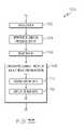
- FIG. 1is a simplified diagram of one embodiment of a system for measuring and displaying joint force data of a patient's joint;
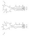
- FIG. 2is a perspective view of one embodiment of a sensor module of the system of FIG. 1 ;
- FIG. 3is a plan view of a top side of the sensor module of FIG. 2 ;
- FIG. 4is a plan view of a bottom side of the sensor module of FIG. 2 ;
- FIG. 5is an exploded, perspective view of the sensor module of FIG. 2 ;
- FIG. 6is an elevation view of an end of the sensor module of FIG. 2 ;
- FIG. 7is a graph of one embodiment of a display protocol for the displays of the sensor module of FIG. 2 ;
- FIG. 8is a simplified diagram of one embodiment of a sensor array of the sensor module of FIG. 2 ;
- FIG. 9is a simplified diagram of another embodiment of the sensor array of the sensor module of FIG. 2 ;
- FIG. 10is a simplified block diagram of one embodiment of an electrical circuit of the sensor module of FIG. 2 ;
- FIG. 11is a simplified flow diagram of one embodiment of a method for determining and displaying joint force data that may be executed by the sensor module of FIG. 2 ;
- FIG. 12is a simplified flow diagram of one embodiment of a method for displaying relative joint force data that may be executed by the sensor module of FIG. 2 ;
- FIG. 13is a perspective view of another embodiment of a sensor module of the system of FIG. 1 ;
- FIG. 14is a perspective view of another embodiment of a sensor module of the system of FIG. 1 ;
- FIG. 15is a perspective view of another embodiment of a sensor module of the system of FIG. 1 ;
- FIG. 16is a perspective view of another embodiment of a sensor module of the system of FIG. 1 ;
- FIG. 17is a perspective view of another embodiment of a sensor module of the system of FIG. 1 ;
- FIG. 18is a perspective view of another embodiment of a sensor module of the system of FIG. 1 ;
- FIG. 19is a perspective view of another embodiment of a sensor module of the system of FIG. 1 ;
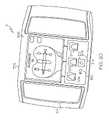
- FIG. 20is a perspective view of one embodiment of a display module of the system of FIG. 1 ;
- FIG. 21is a plan view of the display module of FIG. 20 ;
- FIG. 22is a simplified block diagram of one embodiment of an electrical circuit of the display module of FIG. 20 ;
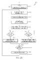
- FIG. 23is a simplified flow diagram of one embodiment of a method for displaying joint force data
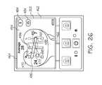
- FIGS. 24-26are illustrative screenshots that may be displayed to a user on the display module of FIG. 20 ;
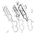
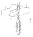
- FIG. 27is a perspective view of one embodiment of a joint distactor of the system of FIG. 1 having the sensor module of FIG. 2 coupled therewith;
- FIG. 28is an elevation view of an end of the joint distactor of FIG. 27 ;
- FIG. 29is a top plan view of the joint distactor of FIG. 27 ;
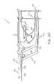
- FIG. 30is a side elevation view of the joint distactor of FIG. 27 ;
- FIG. 31is a perspective view of another embodiment of a joint distactor of the system of FIG. 1 ;
- FIG. 32is a simplified block diagram of one embodiment of a computer assisted surgery system of the system of FIG. 1 ;
- FIG. 33is a simplified flow diagram of one embodiment of a method for performing an orthopaedic surgical procedure using the computer assisted surgery system of FIG. 32 ;
- FIG. 34is a simplified flow diagram of one embodiment of a method for determining and displaying navigation and joint force data that may be executed by the computer assisted surgery system of FIG. 32 ;
- FIG. 35is a simplified flow diagram of one embodiment of a method for determining and displaying flexion angle and force data of a patient's joint that may be executed by the computer assisted surgery system of FIG. 32 ;
- FIG. 36is a simplified flow diagram of one embodiment of a method for performing an orthopaedic surgical procedure using the system of FIG. 1 ;
- FIG. 37is a perspective view of a patient's joint in extension during an orthopaedic surgical procedure using the sensor module of FIG. 2 ;
- FIG. 38is a perspective view of a patient's joint during an orthopaedic surgical procedure using the distractor and sensor module of FIG. 20 ;
- FIG. 39is another perspective view of a patient's joint in flexion during an orthopaedic surgical procedure using the sensor module of FIG. 2 ;
- FIG. 40is another perspective view of a patient's joint in extension during an orthopaedic surgical procedure using the sensor module of FIG. 2 ;
- FIG. 41is another perspective view of a patient's joint in flexion during an orthopaedic surgical procedure using the sensor module of FIG. 2 .
- Terms representing anatomical referencessuch as anterior, posterior, medial, lateral, superior, inferior, etcetera, may be used throughout this disclosure in reference to both the orthopaedic implants described herein and a patient's natural anatomy. Such terms have well-understood meanings in both the study of anatomy and the field of orthopaedics. Use of such anatomical reference terms in the specification and claims is intended to be consistent with their well-understood meanings unless noted otherwise.
- a system 10 for determining and displaying joint forces of a patient's joint during an orthopaedic surgical procedureincludes a sensor module 12 , a hand-held display module 14 , and a joint distractor 16 .
- the system 10may also includes a computer assisted surgery system (CAOS) system 18 in some embodiments.
- CAOScomputer assisted surgery system
- the sensor module 12is configured to be inserted into a patient's joint and provide a visual indication of the joint forces to an orthopaedic surgeon.
- the sensor module 12provides a visual indication of the relative or balance of the medial-lateral joint forces of a patient's knee joint.
- the sensor module 12may also be configured to transmit joint force data to the hand-held display module 14 via a wireless communication link 20 and/or the computer assisted surgery system 18 via a wireless communication link 22 .
- the display module 14 and/or computer assisted surgery system 18are configured to display the joint force data, or data derived therefrom, to an orthopaedic surgeon.
- the sensor module 12may be coupled to the joint distractor 16 to provide visual indication of the joint forces of the patient's joint during distraction thereof as discussed below.
- the sensor module 12includes a sensor housing 30 and a handle 32 coupled to the sensor housing 30 .
- the sensor housing 30is sized and shaped to be positioned in a joint of the patient.
- the sensor housing 30is embodied as a tibial paddle 34 , which is shaped to be positioned in a knee joint of the patient.
- the sensor housing 30may be configured to be used with other joints of the patient in other embodiments as discussed in more detail below in regard to FIGS. 11 and 12 .
- the tibial paddle 34is configured to be positioned on a proximal plateau of a patient's resected tibia (see, e.g., FIG. 29-33 ). As discussed in more detail below, the tibial paddle 34 may be placed in contact with the patient's tibia or may be placed on an intervening platform or other member. Additionally, the sensor module 12 may be used on the patient's left or right knee. For example, the sensor module 12 may be used on a patient's left knee via a medial surgical approach wherein the tibial paddle 34 is inserted into the patient's left knee joint via a medial capsular incision. In such position, as discussed below, the handle 32 extends out of the medial capsular incision.
- the module 12may be used on the patient's left knee via a lateral surgical approach wherein the tibial paddle 34 is inserted into the patient's left knee joint via a lateral capsular incision. Again, in such position, the handle 32 extends out of the lateral capsular incision.
- sensor module 12may be used on the patient's left or right knee using a medial or lateral surgical approach.
- the sensor module 12 and the system 10are described below with reference to an orthopaedic surgical procedure using a medial surgical approach (i.e., using a medial capsular incision to access the patient's joint).
- a medial surgical approachi.e., using a medial capsular incision to access the patient's joint.
- lateral surgical approach proceduresi.e., lateral and medial
- some structuresare described using particular anatomical references (e.g., lateral and medial) with the understanding that such references would be flipped or switched when the module 12 is used in a lateral surgical approach procedure.
- a “medial side” of the tibial paddle 34becomes a “lateral side” of the tibial paddle 34 when used in a lateral surgical approach procedure.
- the tibial paddle 34is substantially planar and has a shape generally corresponding to the shape of the orthopaedic prosthesis to be implanted in the patient.
- the tibial paddle 34has a shape generally corresponding to a knee prosthesis of a particular size.
- the paddle 34(or sensor housing 30 ) may have a shape generally corresponding to other types of orthopedic prostheses such as a hip prosthesis, a shoulder prosthesis, an ankle prosthesis, a spine prosthesis, or a patella prosthesis.
- the illustrative tibial paddle 34includes a curved anterior side 36 , a curved lateral side 38 , a curved medial side 40 , and a curved posterior side 42 , each shaped to approximate the shape a tibial bearing of an orthopaedic knee prosthesis.
- the lateral side 38 and the medial side 40are lateral and medial sides, respectively, in those embodiments wherein the sensor module 12 is used in a lateral surgical approach procedure.
- the posterior side 42includes a posterior notch 44 to allow the tibial paddle 34 to be positioned around the soft tissue of the patient's joint such as the posterior cruciate ligament.
- the posterior notch 44may also provide a mount for other surgical devices such as a trail post for rotating mobile bearing trails. Further, in some embodiments, the posterior notch 44 may be extended or otherwise have other configurations so as to provide a mount for other orthopaedic surgical devices such as fixed and/or mobile tibial trials or the like.
- the overall size of the tibial paddle 34may be selected based on the particular anatomical structure of the patient.
- the tibial paddle 34may be provided in various sizes to accommodate patients of varying sizes. It should be appreciated that the general shape and size of the paddle 34 (and sensor housing 30 ) is designed and selected such that the paddle 34 or housing 30 does not significantly overhang with respect to the associated bony anatomy of the patient such that the paddle 34 or housing 30 nor adversely impinge the surrounding soft tissue.
- the handle 32includes a pair of displays 50 , 52 coupled to a first end 54 of the handle 32 .
- a second end 56 of the handle 32 opposite the first end 54is coupled to the tibial paddle 34 .
- the handle 32 and tibial paddle 34are substantially monolithic in structure.
- the tibial paddle 34may be removably coupled to the handle 32 via a suitable connector or the like.
- the handle 32extends from a side of the tibial paddle 34 .
- the handle 32extends from the medial side 40 (which is a lateral side when the sensor module 12 is used in a lateral surgical approach procedure).
- the tibial paddle 34may be positioned in a knee joint of a patient without the need to sublux or evert the patient's patella. That is, the tibial paddle 34 may be properly positioned between the patient's proximal tibia and distal femur with the patient's patella in the natural position.
- the surgeonmay flip the sensor module 12 to the proper orientation such that the tibial paddle 34 is inserted into the patient's knee joint through the associated capsular incision.
- the handle 32extends out of the capsular incision and at least one of the displays 50 , 52 is visible to the orthopaedic surgeon.
- the orthopaedic surgeonmay position the sensor module 12 in the orientation illustrated in FIG.
- the orthopaedic surgeonmay position the sensor module 12 in the orientation illustrated in FIG. 4 such that the handle 32 extends from the lateral side of the patient's knee (through the lateral capsular incision) when the tibial paddle 34 is inserted into the knee joint and the display 52 is visible to the surgeon.
- the sensor module 12is configured to assist a surgeon during the performance of an orthopaedic surgical procedure.
- the sensor module 12includes an outer housing 58 formed from a bio-compatible material.
- the outer housing 58may be formed from a bio-compatible plastic or polymer.
- the sensor module 12is configured for single-usage and, as such, is provided in a sterile form.
- the sensor module 12may be provided in a sterile packaging.
- the tibial paddle 34may be designed for single-usage and the handle 32 may be configured to be reusable via an autoclaving procedure or the like.
- the outer housing 58 of the sensor module 12includes an upper housing 60 and a lower housing 62 , which are coupled to each other.
- the upper housing 60 and the lower housing 62are mirror images of each other.
- the upper housing 60includes an upper tibial paddle housing 64 and an upper handle housing 66 .
- the lower housing 62includes a lower tibial paddle housing 68 and a lower handle housing 70 .
- the display 50is coupled to the end 54 of the upper housing 60 and the display 52 is coupled to the 54 of the lower housing 62 .
- the displays 50 , 52are illustratively embodied as arrays of light emitting diodes. However, in other embodiments, the displays 50 , 52 may be embodied as other types of displays such as liquid crystal displays, segmented displays, and/or the like. In the illustrative embodiment of FIG. 6 , each of the displays 50 , 52 includes five separate light emitting diodes 80 , 82 , 84 , 86 , 88 .
- the central light emitting diodes 84are illuminated when the medial-lateral joint forces of the patient's knee joint are approximately equal. Additionally, the light emitting diodes 80 and/or 82 are illuminated when the medial joint force is greater than the lateral joint force of the patient's knee joint by a predetermined threshold amount and the light emitting diodes 86 and 88 are illuminated when the lateral joint force is greater than the medial joint force of the patient's knee by the predetermine threshold amount (again, assuming a medial surgical approach). As shown in FIG.
- the light emitting diodes 80 , 82 , 84 , 86 , 88 of the displays 50 , 52are arranged such that the light emitting diodes 80 , 82 correspond with the medial side 40 of the tibial paddle 34 and the light emitting diodes 86 , 88 correspond with the lateral side 38 of the tibial paddle 34 regardless of the orientation (i.e., regardless of whether the upper housing 60 or the lower housing 62 is facing upwardly).
- the light emitting diodes 80 , 82 , 84 , 86 , 88may be illuminated according to a predetermined display protocol to provide a visual indication to the surgeon of the relative medial-lateral joint force balance.
- a predetermined display protocolto provide a visual indication to the surgeon of the relative medial-lateral joint force balance.
- an orthopaedic surgeonmay visual determine which side of the patient's joint is exerting a greater amount of force and the general magnitude of such force relative to the opposite side of the patient's joint.
- one illustrative display protocolis presented in graph 170 in FIG. 7 .
- only the light emitting diode 88is illuminated if the medial-lateral joint force balance is 30% medial-70% lateral, respectively, or laterally greater. However, both light emitting diodes 86 and 88 are illuminated if the medial-lateral joint force balance is about 35% medial-65% lateral, respectively. If the medial-lateral joint force balance is about 40% medial-60% lateral, respectively, only the light emitting diode 86 is illumined. If the medial-lateral joint force balance is about 45% medial-55% lateral, respectively, both light emitting diodes 84 and 86 are illuminated.
- the medial-lateral joint force balanceis about 50% medial-50% lateral, only the light emitting diode 84 is illumined. If the medial-lateral joint force balance is about 55% medial-45% lateral, respectively, both light emitting diodes 82 and 84 are illuminated. If the medial-lateral joint force balance is about 60% medial-40% lateral, respectively, only the light emitting diode 82 is illumined. If the medial-lateral joint force balance is about 65% medial-35% lateral, respectively, both light emitting diodes 80 and 82 are illuminated. Additionally, if the medial-lateral joint force balance is 70% medial-30% lateral, respectively, or medially greater, only the light emitting diode 80 is illuminated. In this way, a visual indication of the relative joint force balance of the patient's knee is provided to the orthopaedic surgeon. Of course, in other embodiments, other display protocols may be used to control and illuminate the displays 50 , 52 .
- the sensor module 12includes a sensor array 90 positioned in the tibial paddle 34 and communicatively coupled to a control circuit 92 positioned in the handle 32 .
- the sensor array 90is “sandwiched” between the upper housing piece 60 and the lower housing piece 62 .
- the upper housing piece 60 and the lower housing piece 62are spaced apart to allow the sensor array 90 to be compressed by the joint force applied to the tibial paddle 34 .
- the upper housing 64includes an outer rim 94 and the lower housing 68 includes an outer rim 96 , which is spaced apart from the outer rim 94 of the upper housing 64 by a distance 98 .
- the sensor array 90includes a plurality of pressure sensors or sensor elements 100 (see FIGS. 8 and 9 ) configured to generate sensor signals indicative of the joint force applied to the sensor array 90 .
- the pressure sensors 100are embodied as capacitive pressure sensors, but may be embodied as other types of sensors in other embodiments.
- the pressure sensors 100 of the sensor array 90are arranged in a particular configuration.
- the sensor array 90includes a set of pressure sensors 102 , 104 , 106 , 108 arranged in a substantially circular pattern and positioned toward the medial side 38 of the tibial paddle 34 .
- the sensor array 90includes a set of pressure sensors 112 , 114 , 116 , 118 arranged in a substantially circular pattern and positioned toward the lateral side 40 of the tibial paddle 34 .
- the sensor array 90also includes a pressure sensor 120 positioned toward the anterior side 36 and medical side 38 of the tibial paddle 34 and a pressure sensor 122 positioned toward the anterior side 36 and lateral side 40 of the tibial paddle 34 .
- the sensor array 90includes a pressure sensor 124 positioned toward the posterior side 42 and medial side 38 of the tibial paddle 34 and a pressure sensor 126 positioned toward the posterior side 42 and lateral side 40 of the tibial paddle 34 .
- sensor arrayshaving pressure sensors arranged in other configurations may be used.
- the pressure sensors 102 , 104 , 106 , 108 and 112 , 114 , 116 , 118are arranged in a pattern corresponding to the shape and size of a tibial paddle of the distractor 16 to improve sensitivity thereto as illustrated in and described below in regard to FIG. 27 .
- the pressure sensors 102 , 104 , 108 , 106 , 120 , 124form a medial set of pressure sensors that generate sensor signals indicative of a medial joint force component of the joint force of a patient's knee (again, assuming a medial surgical approach).
- the pressure sensors 112 , 114 , 118 , 116 , 122 , 124form a lateral set of pressure sensors that generate sensor signals indicative of a lateral joint force component of the joint force of a patient's knee.
- pressure sensors 102 , 104 , 120form an anterior-medial set of pressure sensors that generate sensor signals indicative of an anterior-medial joint force component of the joint force of a patient's knee.
- the pressure sensors 112 , 114 , 122form an anterior-lateral set of pressure sensors that generate sensor signals indicative of an anterior-lateral joint force component of the joint force of a patient's knee.
- the pressure sensors 106 , 108 , 124form a posterior-medial set of pressure sensors that generate sensor signals indicative of a posterior-medial joint force component of the joint force of a patient's knee.
- the pressure sensors 116 , 118 , 126form a posterior-lateral set of pressure sensors that generate sensor signals indicative of a posterior-lateral joint force component of the joint force of a patient's knee.
- the sensor array 90may include more or fewer pressure sensors. In one particular embodiment, the sensor array 90 may include additional medial and lateral pressure sensors for each condyle of the patient's femur. For example, as illustrated in FIG. 9 , the sensor array 90 may include a medial-medial pressure sensor 180 , a medial-lateral pressure sensor 182 , a lateral-medial pressure sensor 184 , and lateral-lateral pressure sensor 186 . That is, the pressure sensor 180 is configured to sense or measure the medial component of the medial joint force exerted by the patient's medial femoral condyle.
- the pressure sensor 182is configured to sense or measure the lateral component of the medial joint exerted by the patient's medial femoral condyle.
- the pressure sensor 184is configured to sense or measure the medial component of the lateral joint force exerted by the patient's lateral femoral condyle.
- the pressure sensor 186is configured to sense or measure the lateral component of the lateral joint exerted by the patient's lateral femoral condyle.
- the particular shape and size of the pressure sensors 180 , 182 , 184 , 186may be selected based on size, shape, and positioning of the other pressure sensors of the sensor array 90 .
- the control circuit 92includes a processor 130 and a memory device 132 .
- the processor 130may be embodied as any type of processor configured to perform the functions described herein.
- the processor 130may be embodied as a separate integrated circuit or as a collection of electronic devices.
- the processormay be a single or multi-core processor. Although only a single processor 130 is illustrated in FIG. 10 , it should be appreciated that in other embodiments, the control circuit 92 may include any number of additional processors.
- the memory device 132may be embodied read-only memory devices and/or random access memory devices.
- the memory device 132may be embodied as or otherwise include electrically erasable programmable read-only memory devices (EEPROM), dynamic random access memory devices (DRAM), synchronous dynamic random access memory devices (SDRAM), double-data rate dynamic random access memory devices (DDR SDRAM), and/or other volatile or non-volatile memory devices.
- EEPROMelectrically erasable programmable read-only memory devices
- DRAMdynamic random access memory devices
- SDRAMsynchronous dynamic random access memory devices
- DDR SDRAMdouble-data rate dynamic random access memory devices
- the control circuit 92may include additional memory devices.
- the processor 130is communicatively coupled to the memory device 132 via signal paths 134 .
- the signal paths 134may be embodied as any type of signal paths capable of facilitating communication between the processor 130 and the memory device 132 .
- the signal paths 134may be embodied as any number of wires, printed circuit board traces, via, bus, intervening devices, and/or the like.
- the processor 130is also communicatively coupled to the sensor array 90 via signal paths 136 . Similar to signal paths 134 , the signal paths 136 may be embodied as any type of signal paths capable of facilitating communication between the processor 130 and the sensor array 90 including, for example any number of wires, printed circuit board traces, via, bus, intervening devices, and/or the like. Additionally, the signal path 136 may include a connector 138 (see FIG. 5 ) configured to receive a plug-end 140 of the sensor array 90 .
- the control circuit 92also includes a power source 142 and associated power control circuitry 144 .
- the power source 142may be embodied as a number of batteries sized to fit in the sensor module 12 .
- the power source 142is electrically coupled to the power control circuitry 144 via signal paths 146 and the power control circuitry 144 is electrically coupled to the processor 130 and other devices of the control circuit 92 via signal paths 148 .
- the signal paths 146 , 148may be embodied as any type of signal paths including, for example any number of wires, printed circuit board traces, via, bus, intervening devices, and/or the like.
- the power circuitry 144may include power control, distribution, and filtering circuitry and is configured to provide or distribute power from the power source 142 to the processor 130 and other devices or components of the control circuit 92 .
- the control circuit 92also includes user controls 150 communicatively coupled to the processor 130 via signal paths 152 .
- the user controls 150are embodied as power buttons 154 (see FIG. 6 ) located on the displays 50 , 52 and selectable by a user to turn the sensor module 12 on.
- the control circuit 92is configured to prevent or otherwise limit the ability of the user from turning off the sensor module 12 via the power buttons 154 or other controls after the sensor module 12 has been turned on. That is, once turned on, the control circuit 92 is configured to remain on until the power source 142 is depleted. Such a configuration ensures that the sensor module 12 is used during a single orthopaedic surgical procedure and is not otherwise reusable in multiple procedures.
- the signal paths 152are similar to the signal paths 134 and may be embodied as any type of signal paths capable of facilitating communication between the user controls 150 and the processor 130 including, for example any number of wires, printed circuit board traces, via, bus, intervening devices, and/or the like.
- the control circuit 92also includes display circuitry 156 for driving and/or controlling the displays 50 , 52 .
- the display circuitry 156is communicatively coupled to the processor 130 via signal paths 158 and to the displays 50 , 52 via signal paths 160 .
- the signal paths 158 , 160may be embodied as any type of signal paths capable of facilitating communication between the processor 130 and display circuitry 156 and the display circuit 156 and displays 50 , 52 , respectively.
- the signal paths 158 , 160may be embodied as any number of wires, printed circuit board traces, via, bus, intervening devices, and/or the like.
- the displays 50 , 52are embodied as an arrangement of light emitting diodes 80 , 82 , 84 , 86 , 88 .
- the sensor module 12is configured to transmit force data to the display module 14 and/or computer assisted orthopaedic surgery (CAOS) system 18 .
- the control circuitincludes transmitter circuitry 162 and an antenna 164 .
- the transmitter circuitry 162is communicatively coupled to the processor 130 via signal paths 166 and to the antenna 164 via signal paths 168 .
- the signal paths 166 , 168may be embodied as any type of signal paths capable of facilitating communication between the transmitter circuitry 162 and the processor 130 and antenna 164 , respectively.
- the signal paths 166 , 168may be embodied as any number of wires, printed circuit board traces, via, bus, intervening devices, and/or the like.
- the transmitter circuitry 162may be configured to use any type of wireless communication protocol, standard, or technologies to transmit the joint force data to the display module 14 and/or computer assisted orthopaedic surgery (CAOS) system 18 .
- CAOScomputer assisted orthopaedic surgery
- the transmitter circuitry 162may be configured to use a wireless networking protocol, a cellular communication protocol such as a code division multiple access (CDMA) protocol, a Bluetooth® protocol, or other wireless communication protocol, standard, or technology.
- CDMAcode division multiple access
- Bluetooth® protocolor other wireless communication protocol, standard, or technology.
- the control circuit 92(see FIG. 10 ) is configured to execute a method 200 for determining joint force data of a patient's joint and providing a visual indication of the medial-lateral balance of the patient's joint force.
- the method 200begins with block 202 in which the control circuit 92 is initialized.
- the control circuit 92may perform any number of system checks, clear any registers of the processor 130 , and/or perform other initialization and/or integrity checks.
- the control circuit 92is configured to perform a handshaking routine in block 204 with the hand-held display device 14 and/or the computer assisted orthopaedic surgery (CAOS) system 18 .
- CAOScomputer assisted orthopaedic surgery
- control circuit 92 and the hand-held display device 14 and/or the computer assisted orthopaedic surgery (CAOS) system 18may be configured to determine communication protocols and/or otherwise establish any type of communication procedures for transmitting the joint force data from the sensor module 12 to the device 14 or system 18 .
- CAOScomputer assisted orthopaedic surgery
- the control circuit 92receives the sensor signals or data from the sensor array 90 .
- the sensor array 90generates sensor signals indicative of a joint force applied to the tibial paddle 34 when the paddle 34 is positioned in the knee joint of a patient.
- the processor 130 of the control circuit 92determines joint force data based on the sensor signals received from the sensor array 90 .
- the joint force datais indicative of the joint force of the patient's knee.
- the joint force datamay be embodied as specific joint force values such as a medial joint force value, a lateral joint force value, an anterior joint force value, and/or a posterior joint force value, each force being determined in Newtons or similar force measurement unit.
- the medial joint forcemay be determined based on the sensor signals from the pressure sensors 102 , 104 , 106 , 108 , 120 , 124 .
- the lateral joint forcemay be determined based on the sensor signals from the pressure sensors 112 , 114 , 116 , 118 , 122 , 126 .
- the anterior joint forcemay be based on the pressure sensor anterior-medial pressure sensors 102 , 104 , 120 and/or the anterior-lateral pressure sensors 112 , 114 , 122 .
- the posterior joint forcemay be based on the sensor signals from the posterior-medial pressure sensors 106 , 108 , 124 and/or the posterior-lateral sensors 116 , 118 , 126 .
- control circuit 92controls or otherwise activates the displays 50 , 52 to display the joint force data determined in block 208 .
- the processor 130may display the determine joint forces or indicia thereof on the displays 50 , 52 .
- control circuit 92may be configured to determine the relative medial-lateral joint force balance and display indicia of such medial-lateral balance on the displays 50 , 52 in blocks 208 , 210 .
- the control circuit 92may execute a method 220 for determining the relative medical-lateral joint forces of the patient's joint.
- the control circuit 92determines medical joint force data based on the sensor signals received from the pressure sensors 102 , 104 , 106 , 108 , 120 , 124 .
- the control circuit 92determines lateral joint force data based on the sensor signals received from the pressure sensors 102 , 104 , 106 , 108 , 120 , 124 .
- the medial and lateral joint force datamay be embodied as the specific joint force determined in Newtons or may be embodied as some representation thereof.
- the medial and lateral joint force datais measured in capacitance. It should be appreciated that the blocks 222 and 224 may be executed in either order.
- the control circuit 92determines the relative medial-lateral balance of the joint force of the patient's joint. To do so, the control circuit 92 compares the medial force data and the lateral force data. For example, in one embodiment, the control circuit 92 is configured to determine a total force value by summing the medial force data and the lateral force data. The control circuit 92 subsequently determines a medial percentage value by dividing the medial force data by the total force value and a lateral percentage value by dividing the lateral force data by the total force value. As such, if the medial and lateral forces of a patient's joint are balanced, the medial percentage value would be determined to be about 50% and the lateral percentage value would be determined to be about 50%. Of course, in some embodiments, the control circuit 92 may be configured to determine only one of the medial and lateral percentage values, the remaining one being known or determined by simple subtraction from 100%.
- the control circuit 92activates or controls the displays 50 , 52 to provide a visual indication of the relative medial-lateral balance of the joint forces of the patient's joint.
- the control circuit 92is configured to activate or illuminate one or more of the light emitting diodes to provide a visual indication of the medial-lateral balance of joint forces.
- the control circuit 92may use any display protocol or pattern of illumination of the light emitting diodes that provides an appropriate indication to the orthopaedic surgeon of such joint forces.
- control circuit 92is configured to control the displays 50 , 52 according to the display protocol 170 illustrated in and discussed above in regard to FIG. 7 .
- the control circuit 92is configured to illuminate the centrally located light emitting diode 84 of the displays 50 , 52 if the medial and lateral joint forces are about equal (i.e., about 50% medial-50% lateral).
- the control circuit 92is configured to illuminate the centrally located light emitting diode 84 and the lateral light emitting diode 86 if the medial-lateral balance of the joint forces is about 45% medial-55% lateral, respectively.
- the control circuit 92is configured to illuminate the lateral light emitting diodes 86 , 88 if the medial-lateral balance of the joint forces is about 35% medial-65% lateral, respectively. Additionally, the control circuit 92 is configured to illuminate the lateral-most light emitting diode 88 if the medial-lateral balance of the joint forces is about 30% medial-70% lateral (or more lateral), respectively. Similarly, the control circuit 92 is configured to illuminate the centrally located light emitting diode 84 and the medial light emitting diode 82 if the medial-lateral balance of the joint forces is about 55% medial-45% lateral, respectively.
- the control circuit 92is configured to illuminate the lateral light emitting diodes 80 , 82 if the medial-lateral balance of the joint forces is about 65% medial-35% lateral, respectively. Additionally, the control circuit 92 is configured to illuminate the medial-most light emitting diode 80 if the medial-lateral balance of the joint forces is about 70% medial-30% lateral (or more medial), respectively.
- sensor module 12provides a visual indication to the orthopaedic surgeon of the relative medial and lateral forces of the patient's joint.
- the orthopaedic surgeoncan perform balancing procedures on the patient's knee joint while monitoring the current balance of the medial and lateral forces via the displays 50 , 52 to achieve the desired balance for the particular patient.
- the sensor module 12includes a display 50 , 52 on either side, the orthopaedic surgeon is provide the visual indication of the joint forces whether the surgeon is operating on the patient's left or right knee.
- the sensor module 12may be configured to transmit the joint force data in block 212 .
- the sensor module 12may transmit the joint force data to the hand-held display 14 and/or computer assisted orthopaedic surgery (CAOS) system 18 in block 212 .
- the transmitted joint force datamay be embodied as the specific joint forces measured in Newtons, for example, or may be representations thereof.
- the sensor signals received from the sensor array 90 or electrical representations of the levels of such signalsmay be transmitted in block 212 .
- the sensor module 12is configured to transmit joint force data that is indicative of the joint forces of the patient's knee joint to the display 14 and/or the system 18 in block 212 .
- the handle 32 and tibial paddle 34may be coupled to each other at other orientations and/or via other intervening structures.
- the sensor module 12may be embodied as a module 230 in which the handle 32 is coupled to the anterior side 36 of the tibial paddle 34 is some embodiments.
- the handle 32extends anteriorly from the patient's knee joint (e.g., through an anterior capsular incision) when the tibial paddle 34 is inserted therein.
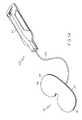
- the sensor module 12may be embodied as a module 232 in which the handle 32 and the tibial paddle 34 are coupled to each other via a wire 234 .
- the wire 234may be embodied as a plurality of wires, cables, or other interconnects that communicatively couple the sensor array 90 positioned in the tibial paddle 34 to the control circuit 92 located in the handle 32 .
- the wire 234is illustratively coupled to the posterior side 36 of the tibial paddle 34 in the embodiment of FIG. 14 , it should be appreciated that the wire 234 may be coupled to the tibial paddle 34 on the lateral side 38 , the medial side 40 , or the posterior side 42 in other embodiments.
- the sensor module 12may be configured for use with joint's other than the patient's knee joint.
- the sensor module 12is embodied as a sensor module 250 , which includes a sensor housing 252 and a handle 254 connected to the sensor housing 252 via an elongated neck 256 .
- the handle 254is similar to the housing 32 of the sensor module 12 and includes the control circuit 92 positioned therein and displays 50 , 52 coupled to an end 258 of the handle 254 .
- the sensor housing 252is configured to be positioned in a ball-and-socket joint of the patient such as the patient's hip joint or shoulder joint.
- the sensor housing 252is substantially “cup”-shaped and includes a concave upper housing piece 260 and a corresponding convex lower housing piece 262 .
- the concave upper housing piece 260defines an inner recess 260 , which may receive a portion of an orthopaedic prosthetic or prosthetic trial or an end of a patient's natural or prosthetic bone during the performance of the orthopaedic surgical procedure.
- the sensor array 90is positioned in the sensor housing 252 and is configured to generate sensor signals indicative of the joint forces of the patient's relative joint.
- the sensor housing 252may be detached from the handle 254 , but communicatively coupled therewith, to improve the ease of use of the sensor module 250 with particular joints.
- the sensor housing 252 and the handle 254may be detached from each other but communicatively coupled via a wire or plurality of wires 266 . That is, the sensor array 90 positioned in the sensor housing 252 is communicatively coupled with the control circuit 90 positioned in the handle 254 .
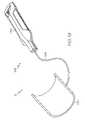
- the sensor module 12may be embodied as a sensor module 270 configured to be used with a spinal joint of the patient.
- the sensor module 270includes a spinal paddle 272 coupled to the handle 254 via the elongated neck 256 .
- the spinal paddle 272is configured to be inserted between the vertebra of the patient's spine.
- the paddle 272has a substantial curricular shape, but may have other shapes in other embodiments.
- the spinal paddle 272includes a notch 274 configured to receive a portion of the patient's spinal cord such that the spinal paddle 272 may be fully inserted into the patient's spine.
- a sensor arrayis included in the spinal paddle 272 to measure or sense the joint force of the patient's spine.
- the spinal sensor arraymay have any number of pressure sensors arranged in a configuration similar to the sensor array 90 discussed above or in another configuration.
- the sensor module 12may be embodied as a sensor module 280 configured to be used with the patella of the patient's knee joint to measure patellofemoral forces.
- the sensor module 280includes a patella paddle 282 coupled to the handle 254 via the elongated neck 256 .
- the patella paddle 282is configured to be inserted between the patient's patella and femur.
- the paddle 282has a substantial oval shape, but may have other shapes in other embodiments.
- a sensor arrayis included in the patella paddle 282 to measure or sense the force exerted by the patient's patella on the patient's femur.
- the patella sensor arraymay have any number of pressure sensors arranged in a configuration similar to the sensor array 90 discussed above or in another configuration.
- the sensor module 12is embodied as a sensor module 290 configured to be used with an ankle joint of the patient.
- the sensor module 290includes an ankle sensor housing 292 coupled to handle 254 via a wire 294 .
- the wire 294may be embodied as a plurality of wires, cables, and/or other interconnects to communicatively couple the ankle sensor housing 292 and the control circuit 92 located in the handle 254 .
- the ankle sensor housing 292is configured to be inserted in an ankle joint of the patient.
- the ankle sensor housing 292is shaped as a half-cylinder, but may have other shapes in other embodiments.
- a sensor arrayis included in the ankle sensor housing 292 to measure or sense the patient's ankle joint force.
- the ankle sensor arraymay have any number of pressure sensors arranged in a configuration similar to the sensor array 90 discussed above or in another configuration.
- the hand-held display module 14includes a housing 300 sized to be held in the hands of an orthopaedic surgeon and used during the performance of an orthopaedic surgical procedure. In this way, the display module 14 is configured to be mobile.
- the display module 14also includes a display 302 coupled to an upper side 304 of the housing 300 .
- a plurality of user input buttons 306 , 308 , 310are also positioned on the upper side 304 of the housing 300 below the display 302 .
- the display module 14also includes a power button 312 . In the illustrative embodiment of FIGS.
- the power button 312is positioned below the row of input buttons 306 , 308 , 310 , but the buttons 306 , 308 , 310 , 312 may be positioned in other configurations and/or orientations in other embodiments.
- the display module 14may include a power-on indicator 314 and a battery state indicator 316 located on the upper side 304 of the housing 300 .
- the hand-held display module 14is configured to be used with the sensor module 12 to receive joint force data form the module 12 and display indicia on the display 302 indicative of the joint forces of the patient's joint. Similar to the sensor module 12 , the display module 14 may be configured to determine the relative medial-lateral and/or anterior-posterior balance of the patient's joint forces and display indicia of such balances on the display 302 . Additionally, the display module 14 may be configured to determine the anterior-posterior balance of the patient's joint forces and display indicia of such balances on the display 302 .
- the display module 14may be configured to determine the specific joint force values (e.g., the medial and lateral joint forces) and display such force values on the display 302 . That is, in addition to an indication of the joint forces relative to each other, the hand-held display module 14 may calculate or otherwise determine the magnitude of the joint force values as measured in a suitable unit of force such as Newtons. Additionally, the display module 14 may also be configured to perform other functions such as store screenshots and data of the patient's joint forces as displayed on the display 302 and download such data to other devices.
- the specific joint force valuese.g., the medial and lateral joint forces
- the hand-held display module 14includes a control circuit 320 positioned in the housing 300 .
- the control circuit 320includes a processor 322 and a memory device 324 .
- the processor 322may be embodied as any type of processor configurable to perform the functions described herein.
- the processor 322may be embodied as a separate integrated circuit or as a collection of electronic devices.
- the processormay be a single or multi-core processors. Although only a single processor 322 is illustrated in FIG. 22 , it should be appreciated that in other embodiments, the control circuit 320 may include any number of additional processors.
- the memory device 324may be embodied read-only memory devices and/or random access memory devices.
- the memory device 324may be embodied as or otherwise include electrically erasable programmable memory devices (EEPROM), dynamic random access memory devices (DRAM), synchronous dynamic random access memory devices (SDRAM), double-data rate dynamic random access memory devices (DDR SDRAM), and/or other volatile or non-volatile memory devices.
- EEPROMelectrically erasable programmable memory devices
- DRAMdynamic random access memory devices
- SDRAMsynchronous dynamic random access memory devices
- DDR SDRAMdouble-data rate dynamic random access memory devices
- the control circuit 320may include additional memory devices.
- the processor 322is communicatively coupled to the memory device 324 via signal paths 326 .
- the signal paths 326may be embodied as any type of signal paths capable of facilitating communication between the processor 322 and the memory device 324 .
- the signal paths 326may be embodied as any number of wires, printed circuit board traces, via, bus, intervening devices, and/or the like.
- the processor 322is also communicatively coupled to the user input buttons 306 , 308 , 310 via signal paths 328 and to the power indicator 314 via signal paths 344 .
- the signal paths 328 , 344may be embodied as any type of signal paths capable of facilitating communication between the processor 322 and the user input buttons 306 , 308 , 310 and the power indicator 314 , respectively.
- the signal paths 328 , 344may include any number of wires, printed circuit board traces, via, bus, intervening devices, and/or the like.
- the user input buttons 306 , 308 , 310are software or “soft” buttons, the functionality of each of which may be determined based on the particular screen displayed on the display 302 .
- the control circuit 320also includes an external power input circuitry 330 , a rechargeable power source 332 such as a rechargeable battery or the like, and power circuitry 334 .
- the external power input circuitry 330is configured to receive a plug of a charger such as a “wall charger” and is communicatively coupled to the rechargeable power source 332 via signal paths 336 .
- the rechargeable power source 332is communicatively coupled to the power circuitry 334 via signal paths 338 .
- the power circuitry 334is communicatively coupled to the processor 332 via signal paths 340 and to the power button 312 via signal paths 342 .
- the signal paths 336 , 338 , 340 , 342may be embodied as any type of signal paths including, for example any number of wires, printed circuit board traces, via, bus, intervening devices, and/or the like.
- the power circuitry 334may include power control, distribution, and filtering circuitry and is configured to provide or distribute power the rechargeable power source 332 to the processor 322 and other devices or components of the control circuit 320 .
- the control circuit 320also includes display circuitry 346 for driving and/or controlling the display 392 .
- the display circuitry 346is communicatively coupled to the processor 322 via signal paths 348 and to the display 302 via signal paths 350 .
- the signal paths 348 , 350may be embodied as any type of signal paths capable of facilitating communication between the processor 322 and display circuitry 346 and the display circuit 346 and display 302 , respectively.
- the signal paths 348 , 350may be embodied as any number of wires, printed circuit board traces, via, bus, intervening devices, and/or the like.
- the hand-held display module 14is configured to receive joint force data from the sensor module 12 .
- the control circuit 320includes receiver circuitry 352 and an antenna 354 .
- the receiver circuitry 352is communicatively coupled to the processor 322 via signal paths 356 and to the antenna 354 via signal paths 358 .
- the signal paths 356 , 358may be embodied as any type of signal paths capable of facilitating communication between the receiver circuitry 352 and the processor 322 and the antenna 354 , respectively.
- the signal paths 356 , 358may be embodied as any number of wires, printed circuit board traces, via, bus, intervening devices, and/or the like.
- the receiver circuitry 352may be configured to use any type of wireless communication protocol, standard, or technologies to receive the joint force data from the sensor module 12 .
- the display module 14may be configured to a wireless networking protocol, a cellular communication protocol such as a code division multiple access (CDMA) protocol, a Bluetooth® protocol, or other wireless communication protocol, standard, or technology to communicate with the sensor module 12 .
- CDMAcode division multiple access
- Bluetooth®or other wireless communication protocol, standard, or technology to communicate with the sensor module 12 .
- the control circuit 320also includes a universal serial bus (USB) interface 360 .
- the USB interface 360is communicatively coupled to the processor 322 via signal paths 362 , which may be embodied as any type of signal paths capable of facilitating communication between the USB interface 360 and the processor 322 .
- the signal paths 362may be embodied as any number of wires, printed circuit board traces, via, bus, intervening devices, and/or the like.
- the USB interface 360may be used to download data, such as joint force data or screenshot data, from the display module 14 to another device such as a computer. Additionally, the USB interface 360 may be used to update the software or firmware of the control circuit 320 .
- the control circuit 320is configured to execute a method 400 for determining and displaying joint force data related to a patient's joint to an orthopaedic surgeon.
- the method 400begins with block 402 in which the control circuit 320 is initialized.
- the control circuit 320may perform any number of system checks, clear any registers of the processor 322 , and/or perform other initialization and/or integrity checks.
- the control circuit 320is configured to perform a handshaking routine in block 404 with the sensor module 12 . During this handshaking routine, the control circuit 320 and the sensor module 12 may be configured to determine communication protocols and/or otherwise establish any type of communication procedures for transmitting the joint force data from the sensor module 12 to the device module 14 .
- the control circuit 320receives the joint force data from the sensor module 12 .
- the joint force datais indicative of the joint force of the patient's knee as indicated by the sensor signals generated by the sensor array 90 of the sensor module 12 .
- the control circuit 320determines a medial joint force value and a lateral joint force value based on the joint force data received in block 406 .
- the medial joint force valueis based on the sensor signals received from the pressure sensors 102 , 104 , 106 , 108 , 120 , 124 and the lateral joint force value is based on the sensor signals received from the pressure sensors 112 , 114 , 116 , 118 , 122 , 126 .
- the control circuit 320determines an average medial/lateral force value based on the medial joint force value and the lateral joint force value determined in block 408 .
- the medial joint force value, the lateral joint force value, and the average joint force valueare subsequently displayed on the display 302 in block 412 .
- the medial joint force value 430is displayed toward a medially designated side 460 of the display 302
- the lateral joint force value 432is displayed toward a laterally designated side 462 of the display 302
- the average force value 434is displayed toward a posterior designated side 464 .
- the control circuit 320determines which mode the orthopaedic surgeon has selected.
- the orthopaedic surgeonmay select a first mode in which indicia of only the medial-lateral balance of the patient's joint forces is displayed on the display 302 or a second mode in which may indicia of the medial-lateral and the anterior-posterior balance of the patient's joint forces is displayed in the display 302 .
- the usermay switch between the two modes by selecting the appropriate user input buttons 306 , 308 , 310 .
- the method 400advances to block 418 in which indicia of the medial-lateral balance of the joint forces of the patient's knee are displayed on the display 302 .
- a screen display 450is presented on the display 302 of the display module 14 .
- the screen display 450includes a background image 470 , which illustrative is embodied as an image of a proximal end of a resected tibia.
- the control circuit 320displays a balance bar 472 on the background image 470 and an icon 474 on the balance bar 472 in a position that indicates the relative medial-lateral balance of the joint forces of the patient's joint.
- the icon 474which is embodied as a rounded rectangle, is displayed on the balance bar 472 toward the lateral side 462 of the screen display 450 (i.e., the side of the display 302 corresponding to the lateral side of the resected tibia image 470 , which illustrative corresponds to the right side of the display 302 ).
- the lateral force component of the total joint force of the patient's knee jointis greater than the medial joint force component.
- the farther way the icon 474 is located from the center of the balance bar 472the greater the respective medial or lateral force component.
- the balance bar 472may be calibrated to provide an indicative of the numerical balance between the medial-lateral forces.
- the background image 470includes an “balanced” icon 476 , illustratively embodied as a rounded rectangular outline, positioned on the background image 470 such that when the icon 474 is located within the boundaries of the icon 476 , the medial joint force and the lateral joint force of the patient's knee are balanced or within a predetermined threshold of each other.
- the medical end 480 of the balance bar 472is positioned toward the anterior side 466 of the display 302 and the lateral end 482 of the balance bar 472 is positioned toward the posterior side 464 of the display 302 .
- Such positioningindicates that the anterior force component of the medical force component is greater than the posterior force component of the medical force component and that the posterior force component of the lateral force component is greater than the anterior force component of the lateral force component. The farther way the ends 480 , 482 are from the anterior-posterior center, the greater the respective anterior or posterior force component.
- the medial end 480 of the balance bar 472is positioned toward the anterior side 466 of the display 302 and the lateral end 482 of the balance bar 472 is positioned toward the posterior side 464 of the display 302 .
- Such positioningindicates that the anterior force component of the medial force component is greater than the posterior force component of the medial force component and that the posterior force component of the lateral force component is greater than the anterior force component of the lateral force component. The farther way the ends 480 , 482 are from the anterior-posterior center, the greater the respective anterior or posterior force component.
- the control circuit 320determines whether the orthopaedic surgeon would like to take a snapshot of the current display in block 422 .
- the orthopaedic surgeonmay take a screenshot of the display 302 by selecting the appropriate user input button 306 , 308 , 310 . Additionally, the screenshot is stored in the memory device 324 in block 424 and may be subsequently downloaded from the display module 14 .
- an icon 484appears in the upper right corner of the display 302 .
- the icon 484displays the average force value that was measured on the respective stored screenshot. Any number of icons 484 may be displayed on the display 302 to indicate corresponding stored screenshots. Additionally, although only a select number of icons 484 may be displayed on the display 302 , the control circuit 320 may be configured to store any number of screenshots.
- a corresponding vertical balance line 486is displayed on the display 302 .
- the balance line 486provides a visual indication of the medial-lateral balance of the joint forces displayed in the associated stored screenshot.
- an anterior-posterior balance line 488is displayed on the display 302 .
- the balance line 488provides a visual indication of the anterior-posterior balance of the medial and lateral forces of the patient's knee joint displayed in the associated stored screenshot.
- the sensor module 12may be coupled to the joint distractor 16 during the performance of an orthopaedic surgical procedure.
- the joint distractor 16includes a cradle 500 sized and configured to receive the sensor module 12 , a first distractor component 502 movably coupled to a side 504 of the cradle 500 , and a second distractor component 506 movably coupled to a side 508 of the cradle 500 opposite the side 504 .
- the cradle 500includes an opening 509 having a shape corresponding to the cross-sectional shape of the handle 32 of the sensor module 12 .
- the sensor module 12may be coupled to the joint distractor 16 by sliding the sensor module 12 handle-first into the cradle 500 .
- the cradle 500includes a locking mechanism 510 that is operable to lock the sensor module 12 in the cradle 500 .
- each of the distractor components 502 , 506includes a mounting bar 512 , 514 , respectively, which is received in a corresponding slot 516 , 518 of the cradle 500 .
- the distractor component 502 , 506may be independently moved in an outwardly direction 520 with respect to the cradle 500 by sliding the respective mounting bars 512 , 514 in or out off the corresponding slots 516 , 518 of the cradle 500 .
- either distractor component 502 , 506may be positioned to extend farther than the other component 502 , 506 such that the joint distractor is selectively configured for use with either knee of the patient from either a medial or lateral approach.
- the distractor components 502 , 506may be adjusted and positioned based on the shape and/or size of the sensor housing 30 of the sensor module 12 , the shape and size of the patient's knee, and/or other criteria.
- the mounting bars 512 , 514may include indicia to provide a visual indication of the amount of extension for each respective distractor component 502 , 506 . Such visual indication may be viewable by the orthopaedic surgeon via windows 522 , 524 defined in the cradle 500 .
- the corresponding mounting bars 512 , 514may be locked into position via use of associated locking mechanisms 526 , 528 . When so locked, the distractor components 502 , 506 are restricted from movement relative to the cradle 500 .
- each distractor component 502 , 506includes a paddle set 530 , 532 and a pair of handles 534 , 536 .
- the paddle set 530 of the distractor component 502includes a tibial paddle 538 and a femoral paddle 540 .
- the paddle set 532 of the distractor component 506includes a tibial paddle 542 and a femoral paddle 544 .
- the handles 534may be operated to move the femoral paddle 540 with respect to the tibial paddle 538 (e.g., upwardly from the tibial paddle 538 ).
- the handles 536may be operated to move the femoral paddle 544 with respect to the tibial paddle 542 (e.g., upwardly from the tibial paddle 538 ).
- the tibial paddles 538 , 542 and the femoral paddles 540 , 544are biased to a closed or contacting position via springs 546 , 548 , which are illustratively positioned within the handles 534 , 536 .
- each pair of handles 534 , 536includes an associated locking mechanism 550 , 552 , respectively, which is operable to lock the handles 534 , 536 , and thereby the associated tibial paddles 538 , 542 and femoral paddles 540 , 544 , in a selected position.
- the sensor module 12is positioned in the cradle 500 and secured in place via the locking mechanism 510 .
- the distractor components 502 , 506may be positioned such that the tibial paddles 538 , 542 contact the tibial paddle 34 of the sensor module 12 as illustrated in FIG. 20 .
- the tibial paddles 538 , 542have a substantially circular shape generally corresponding to the circular orientation of the pressure sensor 102 , 104 , 106 , 108 and the circular orientation of the pressure sensors 112 , 114 , 116 , 118 .
- the joint distractor 16 and sensor module 12may then be inserted into the patient's joint (e.g., between the proximal end of the patient's tibia and the distal end of the patient's femur).
- the joint distractor 16may be subsequently used to distract the patient's joint and, in response to the joint force applied to the tibial paddle 34 , the sensor module 12 displays the medial-lateral balance of the joint forces of the joint at the selected degree of distraction.
- an orthopaedic surgeonmay use the distractor 16 and sensor module 12 to adjust and monitor the relative joint forces of the patient's joint during the performance of the orthopaedic surgical procedure.
- the femoral paddles 540 , 544pivot with respect to the tibial paddles 538 , 542 about a pivot joint 554 (see FIG. 30 ). As such, the femoral paddles 540 , 544 are moved to an oblique orientation relative to the tibial paddles 538 , 542 during use.
- the distractor 16may include a four-bar linkage 272 or other mechanism configured such that the femoral paddles 540 , 544 are moved to a substantially parallel orientation relative to the tibial paddles 538 , 542 during use.
- the femoral paddles 540 , 544 and the tibial paddles 538 , 542remain substantially parallel to each other as the femoral paddles 540 , 544 are moved away from the tibial paddles 538 , 542 .
- the distractor components 502 , 506are but one illustrative embodiment of distractor components to which the cradle 500 may be coupled and, in other embodiments, the cradle 500 may be coupled to other types of distractor components configured to operate in manners similar to or different from the distractor components 502 , 506 .
- the sensor module 12may be configured for use with the computer assisted orthopaedic surgery (CAOS) system 18 .
- the sensor module 12is configured to transmit the joint force data to the system 18 .
- the computer assisted orthopaedic surgery (CAOS) system 18includes a computer 600 , a display 602 , and a camera unit 604 .
- the computer 600is communicatively coupled to the display 602 via signal paths 606 and to the camera unit 604 via signal paths 608 .
- the signal paths 606 , 608may be embodied as any type of signal paths capable of facilitating electrical communication between the computer 600 and the display 602 and the computer 600 and the camera unit 604 , respectively.
- the signal pathsmay be embodied as any number of wires, printed circuit board traces, via, bus, intervening devices, and/or the like.
- the display 602may be embodied as any type of device such as a liquid crystal display monitor, a cathode ray tube (CRT) display monitor, or the like. Additionally, in some embodiments, the display 602 may be embodied as a “heads-up” display. In such embodiments, the signal path 606 may be embodied as a wired or wireless signal path.
- the camera unit 604includes two or more cameras 610 , which are positioned such that reflective arrays 620 coupled to the relevant bones of a patient 612 are in the field of view 614 of the cameras 610 .
- the computer 600includes a processor 622 , a memory device 624 , and a receiver or receiver circuitry 626 .
- the processor 622may be embodied as any type of processor configurable to perform the functions described herein.
- the processor 622may be embodied as a separate integrated circuit or as a collection of electronic devices.
- the processormay be a single or multi-core processors. Although only a single processor 622 is illustrated in FIG. 32 , it should be appreciated that in other embodiments, the computer 600 may include any number of additional processors.
- the memory device 624may be embodied read-only memory devices and/or random access memory devices.
- the memory device 624may be embodied as or otherwise include electrically erasable programmable memory devices (EEPROM), dynamic random access memory devices (DRAM), synchronous dynamic random access memory devices (SDRAM), double-data rate dynamic random access memory devices (DDR SDRAM), and/or other volatile or non-volatile memory devices.
- EEPROMelectrically erasable programmable memory devices
- DRAMdynamic random access memory devices
- SDRAMsynchronous dynamic random access memory devices
- DDR SDRAMdouble-data rate dynamic random access memory devices
- the computer 600may include additional memory devices.
- the receiver circuitry 626may be configured to use any type of wireless communication protocol, standard, or technologies to receive the joint force data from the sensor module 12 .
- the computer 600may be configured to communicate using a wireless networking protocol, a cellular communication protocol such as a code division multiple access (CDMA) protocol, a Bluetooth® protocol, or other wireless communication protocol, standard, or technology to communicate with the sensor module 12 .
- CDMAcode division multiple access
- Bluetooth®or other wireless communication protocol, standard, or technology to communicate with the sensor module 12 .
- the computer assisted orthopaedic surgery (CAOS) system 18is configured to provide surgical navigation by tracking and displaying the position of the patient's relevant bony anatomy (e.g., the patient's tibia and femur) to which the reflective arrays 620 are coupled and provide an amount of surgical procedure walk-through. Additionally, the computer assisted orthopaedic surgery (CAOS) system 18 is configured to receive the joint force data from the sensor module 12 and display the joint force data or other indicia of the joint forces of the patient's joint on the display 602 .
- CAOScomputer assisted orthopaedic surgery
- the computer 600may execute a method 700 for performing an orthopaedic surgical procedure as illustrated in FIG. 33 .
- the method 700begins with block 702 in which the system 18 is initialized.
- the computer 600may perform any number of system checks, clear any registers of the processor 622 , and/or perform other initialization and/or integrity checks.
- any number of settings, preferences, and calibrations of the CAOS system 18may be established and performed in block 702 .
- the video settings of the display 602may be selected, the language displayed by the computer 600 may be chosen, and the touch screen of the display device 602 , if applicable, may be calibrated in block 702 .
- the selections and preferences of the orthopaedic surgical procedureare chosen by the surgeon. Such selections may include the type of orthopaedic surgical procedure that is to be performed (e.g., a total knee arthroplasty), the type of orthopaedic implant that will be used (e.g., make, model, size, fixation type, etc.), the sequence of operation (e.g., the tibia or the femur first), and the like.
- the bones of the patientare registered in block 706 . To do so, the reflective arrays 620 are coupled with the relevant bones of the patient (e.g., the tibia and femur of the patient).
- the contours of such bonesare registered using an appropriate registration tool. To do so, a pointer end of such tool is touched to various areas of the bones to be registered.
- the computer 600displays rendered images of the bones wherein the location and orientation of the bones are determined based on the reflective arrays coupled therewith and the contours of the bones are determined based on the registered points.
- one or more surgical toolsmay be registered with the computer assisted orthopaedic surgery (CAOS) system in block 706 .
- CAOScomputer assisted orthopaedic surgery
- the computer 600in cooperation with the camera unit 604 , displays the images of the surgical steps of the orthopaedic surgical procedure and associated navigation data (e.g., location of surgical tools) in block 708 .
- the process step 708may include any number of sub-steps in which each surgical procedure step is displayed to the orthopaedic surgeon in sequential order along with the associated navigational data.
- the computer 600receives joint force data from the sensor module 12 .
- the joint force datais indicative of the joint force of the patient's knee as indicated by the sensor signals generated by the sensor array 90 of the sensor module 12 .
- the computer 600displays the joint force data or other data derived therefrom that is indicative of the joint forces of the patient's joint on the display 602 .
- the computer 600may be configured to determine any one or more joint force values based on the joint force data in block 712 .
- the computer 600may be configured to determine a medial joint force value and a lateral joint force value based on the joint force data received in block 710 .
- Such medial joint force valueis based on the sensor signals received from the pressure sensors 102 , 104 , 106 , 108 , 120 , 124 and the lateral joint force value is based on the sensor signals received from the pressure sensors 112 , 114 , 116 , 118 , 122 , 126 .
- the computer 600may also determine an average medial/lateral force value based on the medial joint force value and the lateral joint force value. In such embodiments, the medial joint force value, the lateral joint force value, and the average joint force value are subsequently displayed on the display 602 in block 712 .
- the computer 600may be configured to determine the medial-lateral and/or anterior-posterior balance of the joint forces based on the joint force data and display indicia of joint force balance on the display 602 in a manner similar to the hand-held display module 14 .
- the computer 600may present displays similar to the displays 450 , 452 , 454 illustrated in and described above in regard to FIGS. 24 , 25 , and 26 , respectively, in block 412 .
- the computer assisted orthopaedic surgery (CAOS) system 18may be configured to determine and display joint force data on the display 602 in association with the navigation data.
- the computer 600may execute a method 720 for displaying joint force data in association with navigation data as illustrated in FIG. 34 .
- the method 720includes a block 722 in which the computer 600 receives joint force data from the sensor module 12 .
- the joint force datais indicative of the joint force of the patient's knee as indicated by the sensor signals generated by the sensor array 90 of the sensor module 12 .
- the computer 600determines the medial, lateral, and/or average joint force values based on the joint force data received in block 722 .
- the computer 600determines the location and orientation of the patient's relevant bones, such as the patient's femur and tibia in those embodiments wherein the patient's knee is undergoing an orthopaedic surgical procedure, in block 724 . Subsequently, in block 728 , the computer 600 displays the joint force values determined in block 722 and the image of the knee joint in block 728 . As such, the computer 600 may be used to display, for example, the flexion and extension gaps of the medial and lateral condyles of the patient's knee and contemporaneously display the associated medial, lateral, and/or average joint force values of the patient's knee. By monitoring the flexion and extension gaps and the associated joint force values, the orthopaedic surgeon may determine the appropriate amount of gap or joint force for a particular orthopaedic procedure.
- the computer 600may also be configured to determine other anatomical data based on the orientation and position of the patients bones determined in block 726 and display such anatomical data along with the associated joint force values. For example, in one embodiment, the computer 600 is configured to determine the varus/valgus angle of the patient's knee and display the associated medial and lateral force values. Additionally, the computer 600 may be configured to determine the loaded condyle based on the medial and lateral force values and identify the loaded condyle to the orthopaedic surgeon on the display 602 .
- the computer 600may be configured to store the anatomical data, the joint force values, and/or other surgical data such as the implant type size, patient identification data, and/or the like in association with each other in the memory device 624 or other storage device.
- the computer 600may also be configured to determine and display a graph of flexion angle and associated joint force values in some embodiments. To do so, the computer 600 executes a method 730 as illustrated in FIG. 35 .
- the method 730includes a block 732 in which the computer 600 receives joint force data from the sensor module 12 . Again, the joint force data is indicative of the joint force of the patient's knee as indicated by the sensor signals generated by the sensor array 90 of the sensor module 12 .
- the computer 600determines the medial, lateral, and/or average joint force values based on the joint force data received in block 732 .
- the computer 600determines the flexion angle of the patient's knee in block 736 . To do so, the computer 600 determines the relative location of the patient's tibia and femur and determines the flexion angle defined therebetween based on these locations. In block 738 , the computer 600 stores the joint force data determined in block 734 and the flexion angle data determined in block 738 . The method repeats through blocks 732 , 734 , 736 to collect data and each, or every predetermined, flexion angle within a desired range of flexion. After such data has been collected, the method 730 advances to block 740 in which the computer 600 displays a graph of joint force values versus flexion angle. Such graph may include medial and lateral joint force values or may include an average joint force values depending on the preference of the orthopaedic surgeon.
- the sensor module 12may be used during the performance of an orthopaedic surgical procedure to monitor the relative medial-lateral balance of the patient's joint forces.
- a surgical method 800 for performing a total knee arthroplasty procedure using the sensor module 12is illustrated in FIG. 36 .
- the method 800begins with block 802 in which the proximal tibia 900 of the patient is resected. By resecting the patient's tibia 900 , a resected planar surface or plateau is established on the proximal end of the tibia.
- CAOScomputer assisted orthopaedic surgery
- the distal end of the patient's femur 902may be resected in block 804 .
- the patient's kneeis placed in extension.
- the patient's kneeis distracted while in extension and the joint forces are balanced.
- the orthopaedic surgeonmay place the tibial paddle 34 of the sensor module 12 in the patient's knee joint.
- the tibial paddle 34is placed on the resected plateau 850 of the patient's proximal tibia as illustrated in FIG. 37 .
- the tibial paddle 34may be placed in contact with the patient's tibia or may be placed on a membrane or other intervening member.
- a spacer block 832may be used to distract the patient's knee in extension a desired amount.
- the sensor module 12may be coupled to the joint distractor 16 , which may be inserted into the patient's knee joint and operated to distract the joint to the desired amount.
- the patient's knee jointis distracted in extension an amount necessary to establish a generally rectangular joint gap (i.e., the resected plateau 850 of the patient's tibia is approximately parallel with the resected distal end of the patient's femur).
- the orthopaedic surgeonmay balance the medial and lateral joint forces. To do so, the orthopaedic surgeon may perform a ligament release or balancing procedure to reduce the medial or lateral force of the patient's knee. While so doing, the orthopaedic surgeon may monitor the display 50 , 52 of the sensor module 12 and/or the hand-held display module 14 to determine which side to release and when the medial and lateral forces are approximately equal (e.g., when the middle light emitting diode 84 is illuminated).
- the orthopaedic surgeonmay decide that an alternative joint force balance, such as a 45%/55% medial-lateral joint force balance, is desirable for the particular patient based on such criteria as, for example, the age of the patient, the gender of the patient, the extent of soft tissue damage of the patient's joint, the extent of pre-operative deformity of the patient's joint, etc.
- an alternative joint force balancesuch as a 45%/55% medial-lateral joint force balance
- CAOScomputer assisted orthopaedic surgery
- the patient's jointis placed in flexion in block 812 .
- the patient's kneeis distracted while in flexion to the desired balance of joint forces.
- the orthopaedic surgeonmay again place the tibial paddle 34 of the sensor module 12 on the resected plateau 850 of the patient's proximal tibia 900 .
- the tibial paddle 34may be placed in contact with the patient's tibia or may be placed on a membrane or other intervening member.
- the orthopaedic surgeonmay distract the patient's knee using, for example, the distractor 16 , 560 , or other distractor to distract each condyle of the patient's femur differing amounts until the medial and lateral joint forces are approximately equal. By, equalizing the medial and lateral joint forces, the rotation of the femur is established.
- a number of additional resectioning cutsare performed on the patient's distal femur 902 in block 816 .
- a cutting block 860may be coupled to the joint distractor 16 and used to perform an anterior femoral cut, a posterior femoral cut, and/or chamfer cuts on the patient's distal femur 902 while the patient's joint is distracted in flexion.
- the cutting block 860is positioned such that the anterior and posterior femoral cuts are substantially parallel to the tibial cut while the patient's knee is distracted in flexion as discussed above.
- the cutting block 860may be positioned such that the angle of the anterior and posterior femoral cuts correspond to particular angles of the intended implant. As such, the anterior and posterior femoral cuts are performed with the femur rotated to the desired position. The position of the cutting block 860 may also be adjusted anteriorly or posteriorly to set the flexion gap for the orthopaedic implant.
- the rotation of the femur in flexionis predetermined based on anatomical references such as the posterior condyles, Whiteside's line, and/or the transepicondylar axis.
- the anterior femoral cut, a posterior femoral cut, and/or chamfer cutsare performed on the patient's distal femur 902 based on the predetermined rotation of the femur.
- a spacer block 854may be used to check or verify such femoral cuts.
- ligamentous releasemay be used by the surgeon to balance or define the desired medial-lateral joint forces. In such embodiments, the orthopaedic surgeon may also verify that ligament releases performed in flexion do not adversely affect the joint force balance in extension.
- the joint force balance of the patient's knee jointis verified in block 818 .
- the orthopaedic surgeonmay place the tibial paddle 34 of the sensor module 12 on the resected plateau 850 of the patient's proximal tibia 900 as illustrated in FIGS. 40 and 41 .
- a trial tibial insert or bearing 862may be placed on the tibial paddle 34 and a trial femoral component may be temporarily coupled to the distal end of the patient's femur 902 .
- the patient's knee jointmay then be moved through various degrees of flexion as illustrated in FIG. 41 while the orthopaedic surgeon monitors the associated joint force balance as indicated by the displays 50 , 52 of the sensor module 12 to verify that the desired joint for balance is maintained throughout flexion of the patient's joint.
- joint forcesgenerally correspond to the joint pressure of the patient's joint over a defined area.
- the sensor module 12 , the hand-held display module 14 , and the computer assisted surgery system 18may be configured to measure, determine, and display the pressure of the patient's relative joint in addition to or alternatively to the patient's joint force.
- the pressure of the patient's jointmay be determined based on the known area of each sensor of the pressure sensors or sensor elements 100 of the sensor array 90 .
Landscapes
- Health & Medical Sciences (AREA)
- Life Sciences & Earth Sciences (AREA)
- Surgery (AREA)
- Heart & Thoracic Surgery (AREA)
- Veterinary Medicine (AREA)
- Oral & Maxillofacial Surgery (AREA)
- Public Health (AREA)
- General Health & Medical Sciences (AREA)
- Animal Behavior & Ethology (AREA)
- Engineering & Computer Science (AREA)
- Biomedical Technology (AREA)
- Biophysics (AREA)
- Medical Informatics (AREA)
- Molecular Biology (AREA)
- Pathology (AREA)
- Orthopedic Medicine & Surgery (AREA)
- Physics & Mathematics (AREA)
- Transplantation (AREA)
- Dentistry (AREA)
- Nuclear Medicine, Radiotherapy & Molecular Imaging (AREA)
- Physical Education & Sports Medicine (AREA)
- Rheumatology (AREA)
- Cardiology (AREA)
- Vascular Medicine (AREA)
- Physiology (AREA)
- Surgical Instruments (AREA)
- Orthopedics, Nursing, And Contraception (AREA)
- Measurement Of The Respiration, Hearing Ability, Form, And Blood Characteristics Of Living Organisms (AREA)
- Prostheses (AREA)
Abstract
Description
Claims (17)
Priority Applications (3)
| Application Number | Priority Date | Filing Date | Title |
|---|---|---|---|
| US12/415,350US8740817B2 (en) | 2009-03-31 | 2009-03-31 | Device and method for determining forces of a patient's joint |
| EP10156105AEP2238904A1 (en) | 2009-03-31 | 2010-03-10 | Device for determining forces of a patient's joint |
| JP2010077089AJP5710141B2 (en) | 2009-03-31 | 2010-03-30 | Device for determining the force of a patient's joint |
Applications Claiming Priority (1)
| Application Number | Priority Date | Filing Date | Title |
|---|---|---|---|
| US12/415,350US8740817B2 (en) | 2009-03-31 | 2009-03-31 | Device and method for determining forces of a patient's joint |
Publications (2)
| Publication Number | Publication Date |
|---|---|
| US20100249777A1 US20100249777A1 (en) | 2010-09-30 |
| US8740817B2true US8740817B2 (en) | 2014-06-03 |
Family
ID=42173845
Family Applications (1)
| Application Number | Title | Priority Date | Filing Date |
|---|---|---|---|
| US12/415,350Active2031-06-04US8740817B2 (en) | 2009-03-31 | 2009-03-31 | Device and method for determining forces of a patient's joint |
Country Status (3)
| Country | Link |
|---|---|
| US (1) | US8740817B2 (en) |
| EP (1) | EP2238904A1 (en) |
| JP (1) | JP5710141B2 (en) |
Cited By (10)
| Publication number | Priority date | Publication date | Assignee | Title |
|---|---|---|---|---|
| US10085645B2 (en) | 2015-09-30 | 2018-10-02 | DePuy Synthes Products, Inc. | Implant placement method with feedback |
| US10772640B2 (en) | 2016-12-22 | 2020-09-15 | Orthosensor Inc. | Surgical apparatus having a medial plate and a lateral plate and method therefore |
| US11051955B2 (en) | 2012-03-31 | 2021-07-06 | DePuy Synthes Products, Inc. | System and method for validating an orthopaedic surgical plan |
| US11185425B2 (en) | 2016-12-22 | 2021-11-30 | Orthosensor Inc. | Surgical tensor configured to distribute loading through at least two pivot points |
| US11266512B2 (en) | 2016-12-22 | 2022-03-08 | Orthosensor Inc. | Surgical apparatus to support installation of a prosthetic component and method therefore |
| US11284873B2 (en) | 2016-12-22 | 2022-03-29 | Orthosensor Inc. | Surgical tensor where each distraction mechanism is supported and aligned by at least two guide shafts |
| US11291437B2 (en) | 2016-12-22 | 2022-04-05 | Orthosensor Inc. | Tilting surgical tensor to support at least one bone cut |
| US12201534B2 (en) | 2020-01-29 | 2025-01-21 | Howmedica Osteonics Corp. | Load sensor balancer instruments |
| US12324752B2 (en) | 2012-03-31 | 2025-06-10 | Depuy Ireland Unlimited Company | Orthopaedic surgical system for determining joint forces of a patient's knee joint |
| US12408908B2 (en)* | 2018-08-07 | 2025-09-09 | Smith & Nephew, Inc. | Force-indicating retractor device and methods of use |
Families Citing this family (26)
| Publication number | Priority date | Publication date | Assignee | Title |
|---|---|---|---|---|
| WO2013155501A1 (en)* | 2012-04-13 | 2013-10-17 | Conformis, Inc. | Patient adapted joint arthroplasty devices, surgical tools and methods of use |
| US8197489B2 (en)* | 2008-06-27 | 2012-06-12 | Depuy Products, Inc. | Knee ligament balancer |
| US8551023B2 (en) | 2009-03-31 | 2013-10-08 | Depuy (Ireland) | Device and method for determining force of a knee joint |
| US8721568B2 (en) | 2009-03-31 | 2014-05-13 | Depuy (Ireland) | Method for performing an orthopaedic surgical procedure |
| US8661893B2 (en)* | 2010-06-29 | 2014-03-04 | Orthosensor Inc. | Prosthetic component having a compliant surface |
| US8951266B2 (en)* | 2011-01-07 | 2015-02-10 | Restoration Robotics, Inc. | Methods and systems for modifying a parameter of an automated procedure |
| US8690888B2 (en)* | 2011-09-23 | 2014-04-08 | Orthosensor Inc. | Modular active spine tool for measuring vertebral load and position of load |
| US9414940B2 (en)* | 2011-09-23 | 2016-08-16 | Orthosensor Inc. | Sensored head for a measurement tool for the muscular-skeletal system |
| US9381011B2 (en) | 2012-03-29 | 2016-07-05 | Depuy (Ireland) | Orthopedic surgical instrument for knee surgery |
| US10070973B2 (en) | 2012-03-31 | 2018-09-11 | Depuy Ireland Unlimited Company | Orthopaedic sensor module and system for determining joint forces of a patient's knee joint |
| US9545459B2 (en) | 2012-03-31 | 2017-01-17 | Depuy Ireland Unlimited Company | Container for surgical instruments and system including same |
| CN102688097B (en)* | 2012-05-14 | 2014-11-26 | 清华大学 | Attitude acquisition method and system for acetabulum and femoral head in artificial hip joint replacement |
| US9308102B2 (en) | 2013-03-04 | 2016-04-12 | Howmedica Osteonics Corp. | Acetabular cup positioning device |
| US9408557B2 (en) | 2013-03-18 | 2016-08-09 | Orthosensor Inc. | System and method to change a contact point of the muscular-skeletal system |
| US11793424B2 (en) | 2013-03-18 | 2023-10-24 | Orthosensor, Inc. | Kinetic assessment and alignment of the muscular-skeletal system and method therefor |
| EP2976047B1 (en)* | 2013-03-20 | 2017-11-01 | MiRus LLC | Systems and methods for measuring performance parameters related to orthopedic arthroplasty |
| CN104083182A (en)* | 2013-04-01 | 2014-10-08 | 德普伊新特斯产品有限责任公司 | Shaping sensor module and system for determining joint force of knee joints of patient |
| US10470900B2 (en)* | 2016-06-17 | 2019-11-12 | Paragon 28, Inc. | Implants, devices, systems, kits and methods of implanting |
| CN107242907B (en)* | 2017-07-26 | 2020-09-04 | 北京易迈医疗科技有限公司 | Knee joint unicondylar pressure measuring device and system |
| WO2020037380A1 (en)* | 2018-08-24 | 2020-02-27 | Q L Spacer Blocks Pty Ltd | A surgical device |
| CN113423324B (en)* | 2018-10-05 | 2024-11-29 | 豪迈帝凯奥斯泰纳克公司 | Measurement system configured to support installation of ball-and-socket joints and method therefor |
| CN111067675B (en)* | 2019-12-31 | 2021-05-04 | 牛依芃 | Knee joint unicondylar pressure and frictional force measuring device |
| WO2021158972A1 (en)* | 2020-02-07 | 2021-08-12 | New York Society For The Relief Of The Ruptured And Crippled, Maintaining The Hospital For Special Surgery | System and method for quantifying gap assessment examination |
| US12144497B2 (en)* | 2020-09-18 | 2024-11-19 | Board Of Regents, The University Of Texas System | Suture anchor with real-time tension sensor |
| US12370062B2 (en) | 2021-06-04 | 2025-07-29 | Zimmer, Inc. | Independently implantable sensors for orthopedic implants |
| US12232790B2 (en) | 2022-12-30 | 2025-02-25 | IvyTech Design LLC | Adjustable angle orthopedic distractor, compressor, and distractor-compressor |
Citations (205)
| Publication number | Priority date | Publication date | Assignee | Title |
|---|---|---|---|---|
| US4501266A (en) | 1983-03-04 | 1985-02-26 | Biomet, Inc. | Knee distraction device |
| US4566448A (en) | 1983-03-07 | 1986-01-28 | Rohr Jr William L | Ligament tensor and distal femoral resector guide |
| US4795473A (en) | 1987-01-09 | 1989-01-03 | Grimes James B | Extramedullary femoral head-neck prosthesis and method of implanting same |
| US4796610A (en) | 1987-07-02 | 1989-01-10 | Donjoy, Inc. | Lateral impact knee guard and medial collateral ligament knee brace |
| US4804000A (en) | 1987-01-21 | 1989-02-14 | Steve Lamb | Dynamic sagittal knee test apparatus |
| US4808186A (en) | 1988-02-02 | 1989-02-28 | Boehringer Mannheim Corporation | Controlled stiffness femoral hip implant |
| US4822362A (en) | 1987-05-19 | 1989-04-18 | Walker Peter S | Process and apparatus for tibial plateau compenent |
| US4825857A (en) | 1982-02-18 | 1989-05-02 | Howmedica, Inc. | Prosthetic knee implantation |
| US4828562A (en) | 1988-02-04 | 1989-05-09 | Pfizer Hospital Products Group, Inc. | Anterior cruciate ligament prosthesis |
| US4834057A (en) | 1980-03-31 | 1989-05-30 | Physical Diagnostics, Inc. | Dynamic joint motion analysis technique |
| US4856993A (en) | 1985-03-29 | 1989-08-15 | Tekscan, Inc. | Pressure and contact sensor system for measuring dental occlusion |
| US4888021A (en) | 1988-02-02 | 1989-12-19 | Joint Medical Products Corporation | Knee and patellar prosthesis |
| US4892093A (en) | 1988-10-28 | 1990-01-09 | Osteonics Corp. | Femoral cutting guide |
| US4892546A (en) | 1987-05-15 | 1990-01-09 | Howmedica Gmbh | Adjustable prosthesis for a joint bone |
| US4899761A (en) | 1988-03-31 | 1990-02-13 | Brown Mark D | Apparatus and method for measuring spinal instability |
| US4907578A (en) | 1986-07-23 | 1990-03-13 | Petersen Thomas D | Method and instruments for resection of the distal femur |
| US4926847A (en) | 1988-12-27 | 1990-05-22 | Johnson & Johnson Orthopaedics, Inc. | Surgical cutting block |
| US4932974A (en) | 1989-07-06 | 1990-06-12 | Pappas Michael J | Prosthetic device with predetermined crystal orientation |
| US4935023A (en) | 1989-01-09 | 1990-06-19 | Dow Corning Wright | Femoral surface shaping guide for knee implants |
| US4936853A (en) | 1989-01-11 | 1990-06-26 | Kirschner Medical Corporation | Modular knee prosthesis |
| US4938762A (en) | 1987-12-16 | 1990-07-03 | Protek Ag | Reference system for implantation of condylar total knee prostheses |
| US4944756A (en) | 1988-02-03 | 1990-07-31 | Pfizer Hospital Products Group | Prosthetic knee joint with improved patellar component tracking |
| US4959071A (en) | 1988-02-03 | 1990-09-25 | Biomet, Inc. | Partially stabilized knee prosthesis |
| US4963153A (en) | 1987-06-30 | 1990-10-16 | Sulzer Brothers Limited | Metal tibial anchoring part for a partial knee joint prosthesis |
| US4973331A (en) | 1989-03-08 | 1990-11-27 | Autogenesis Corporation | Automatic compression-distraction-torsion method and apparatus |
| US4979949A (en) | 1988-04-26 | 1990-12-25 | The Board Of Regents Of The University Of Washington | Robot-aided system for surgery |
| US4986281A (en) | 1984-08-23 | 1991-01-22 | Starkey Laboratories, Inc. | Method for obtaining a signal for analyzing human and animal joint functions |
| US5002547A (en) | 1987-02-07 | 1991-03-26 | Pfizer Hospital Products Group, Inc. | Apparatus for knee prosthesis |
| US5018514A (en) | 1987-06-11 | 1991-05-28 | Brace Technologies, Inc. | Knee brace |
| US5020797A (en) | 1989-12-15 | 1991-06-04 | Burns Clay A | Method and apparatus for exercising the knee while correcting for tibial subluxation |
| US5032132A (en) | 1990-01-22 | 1991-07-16 | Boehringer Mannheim Corporation | Glenoid component |
| US5033291A (en) | 1989-12-11 | 1991-07-23 | Tekscan, Inc. | Flexible tactile sensor for measuring foot pressure distributions and for gaskets |
| US5037423A (en) | 1983-10-26 | 1991-08-06 | Pfizer Hospital Products Group, Inc. | Method and instrumentation for the replacement of a knee prosthesis |
| US5056530A (en) | 1988-12-15 | 1991-10-15 | University Of Cincinnati | Method of measuring axial force in mammalian fibrous tissue and device |
| US5080675A (en) | 1990-03-12 | 1992-01-14 | Howmedica | Tibial component for a replacement knee prosthesis |
| US5082003A (en) | 1990-01-05 | 1992-01-21 | Orthopedic Systems, Inc. | Apparatus for determining interskeletal distances |
| US5098436A (en) | 1991-03-07 | 1992-03-24 | Dow Corning Wright Corporation | Modular guide for shaping of femur to accommodate intercondylar stabilizing housing and patellar track of implant |
| US5122144A (en) | 1989-09-26 | 1992-06-16 | Kirschner Medical Corporation | Method and instrumentation for unicompartmental total knee arthroplasty |
| US5125408A (en) | 1988-10-24 | 1992-06-30 | The United States Of America As Represented By The Of The Department Of Health And Human Services | Pressure sensor element and method to measure contact stress |
| US5129909A (en) | 1991-03-13 | 1992-07-14 | Sutherland Charles J | Apparatus and method for making precise bone cuts in total knee replacement |
| US5197488A (en) | 1991-04-05 | 1993-03-30 | N. K. Biotechnical Engineering Co. | Knee joint load measuring instrument and joint prosthesis |
| US5207711A (en) | 1990-01-08 | 1993-05-04 | Caspari Richard B | Knee joint prosthesis |
| US5213112A (en) | 1992-01-29 | 1993-05-25 | Pfizer Hospital Products Group, Inc. | Tension meter for orthopedic surgery |
| US5228459A (en) | 1990-01-08 | 1993-07-20 | Caspari Richard B | Method of resecting bone |
| US5234434A (en) | 1992-08-17 | 1993-08-10 | Marlowe Goble E | Mutliple guide sleeve drill guide |
| US5234433A (en) | 1989-09-26 | 1993-08-10 | Kirschner Medical Corporation | Method and instrumentation for unicompartmental total knee arthroplasty |
| US5234435A (en) | 1991-03-08 | 1993-08-10 | Seagrave Jr Richard A | Surgical method and apparatus |
| US5250050A (en) | 1987-02-07 | 1993-10-05 | Pfizer Hospital Products Group, Inc. | Apparatus for knee prosthesis |
| US5257996A (en) | 1991-12-13 | 1993-11-02 | Mcguire David A | Surgical pin passer |
| US5312411A (en) | 1992-10-27 | 1994-05-17 | Smith & Nephew Richards, Inc. | Uni-compartmental femoral knee instruments and prosthesis |
| US5326363A (en) | 1992-09-14 | 1994-07-05 | Zimmer, Inc. | Provisional implant |
| US5329933A (en) | 1991-09-24 | 1994-07-19 | Henry Graf | Device for measuring the angle of movement of two vertebrae |
| US5342367A (en) | 1992-02-20 | 1994-08-30 | Wright Medical Technology, Inc. | Rotationally and angularly adjustable tibial cutting guide and method of use |
| US5358527A (en) | 1991-03-22 | 1994-10-25 | Forte Mark R | Total knee prosthesis with resurfacing and posterior stabilization capability |
| US5364402A (en) | 1993-07-29 | 1994-11-15 | Intermedics Orthopedics, Inc. | Tibial spacer saw guide |
| US5364401A (en) | 1992-10-08 | 1994-11-15 | Wright Medical Technology, Inc. | External alignment system for preparing a femur for an implant |
| US5395401A (en) | 1991-06-17 | 1995-03-07 | Bahler; Andre | Prosthetic device for a complex joint |
| US5417694A (en) | 1993-11-08 | 1995-05-23 | Smith & Nephew Richards Inc. | Distal femoral cutting guide apparatus with anterior or posterior referencing for use in knee joint replacement surgery |
| US5425775A (en) | 1992-06-23 | 1995-06-20 | N.K. Biotechnical Engineering Company | Method for measuring patellofemoral forces |
| US5431652A (en) | 1991-12-25 | 1995-07-11 | Gunze Limited | Bone-treating devices and their manufacturing method |
| US5431653A (en) | 1993-07-06 | 1995-07-11 | Callaway; George H. | Knee joint flexion-gap distraction device |
| US5443518A (en) | 1993-07-20 | 1995-08-22 | Zimmer, Inc. | Knee position indicator |
| US5456724A (en) | 1993-12-15 | 1995-10-10 | Industrial Technology Research Institute | Load sensor for bone graft |
| US5470354A (en) | 1991-11-12 | 1995-11-28 | Biomet Inc. | Force sensing apparatus and method for orthopaedic joint reconstruction |
| US5489311A (en) | 1994-01-21 | 1996-02-06 | Joint Medical Products Corporation | Prosthesis with orientable bearing surface |
| US5496352A (en) | 1994-04-04 | 1996-03-05 | Pacesetter, Inc. | Activity sensors for implantable medical devices |
| US5514144A (en) | 1993-12-20 | 1996-05-07 | Bolton; Carl W. | Drill guide device for the arthroscopic anatomic placement of a straight tibio-femoral bone tunnel for ACL reconstruction |
| US5514183A (en) | 1994-12-20 | 1996-05-07 | Epstein; Norman | Reduced friction prosthetic knee joint utilizing replaceable roller bearings |
| US5520695A (en) | 1992-02-14 | 1996-05-28 | Johnson & Johnson Professional, Inc. | Instruments for use in knee replacement surgery |
| WO1996017552A1 (en) | 1994-12-05 | 1996-06-13 | Intermedics Orthopedics, Inc. | Knee distractor device |
| US5540696A (en) | 1995-01-06 | 1996-07-30 | Zimmer, Inc. | Instrumentation for use in orthopaedic surgery |
| US5562674A (en) | 1995-02-27 | 1996-10-08 | Zimmer, Inc. | Intramedullary rod with guide member locator |
| US5597379A (en) | 1994-09-02 | 1997-01-28 | Hudson Surgical Design, Inc. | Method and apparatus for femoral resection alignment |
| US5611774A (en) | 1992-10-23 | 1997-03-18 | Françoise Ghislaine Dumont | Knee support or replacement apparatus |
| US5613971A (en) | 1995-08-11 | 1997-03-25 | Depuy Inc. | Ratcheting tibial and femoral guide |
| US5643272A (en) | 1994-09-02 | 1997-07-01 | Hudson Surgical Design, Inc. | Method and apparatus for tibial resection |
| US5649929A (en) | 1995-07-10 | 1997-07-22 | Callaway; George Hadley | Knee joint flexion-gap distraction device |
| US5656785A (en) | 1995-08-07 | 1997-08-12 | The Charles Stark Draper Laboratory, Inc. | Micromechanical contact load force sensor for sensing magnitude and distribution of loads and tool employing micromechanical contact load force sensor |
| US5658293A (en) | 1995-10-10 | 1997-08-19 | Zimmer, Inc. | Guide platform associated with intramedullary rod |
| US5669914A (en) | 1996-02-16 | 1997-09-23 | Board Of Regents Of The University Of Colorado | Rotation alignment instrument |
| US5671695A (en) | 1994-07-28 | 1997-09-30 | Depuy Inc. | Replacement ligament graft passer and method |
| US5682886A (en) | 1995-12-26 | 1997-11-04 | Musculographics Inc | Computer-assisted surgical system |
| US5683397A (en) | 1995-02-15 | 1997-11-04 | Smith & Nephew, Inc. | Distal femoral cutting guide apparatus for use in knee joint replacement surgery |
| US5688282A (en) | 1995-08-24 | 1997-11-18 | Benois & Girard & Cie | Distraction apparatus for a knee |
| US5702463A (en) | 1996-02-20 | 1997-12-30 | Smith & Nephew Inc. | Tibial prosthesis with polymeric liner and liner insertion/removal instrument |
| US5702422A (en) | 1995-12-06 | 1997-12-30 | Stone; Kevin R. | Anterior cruciate ligament repair method |
| US5733292A (en) | 1995-09-15 | 1998-03-31 | Midwest Orthopaedic Research Foundation | Arthroplasty trial prosthesis alignment devices and associated methods |
| US5735904A (en) | 1995-07-05 | 1998-04-07 | Pappas; Michael J. | Spacer for establishng prosthetic gap and ligamentous tension |
| US5743909A (en) | 1996-06-24 | 1998-04-28 | Collette; Michel | Radiological method for preoperative determination of isometric attachment points of an ACL graft, surgical aiming instrument and method of use |
| US5769894A (en) | 1997-02-05 | 1998-06-23 | Smith & Nephew, Inc. | Graft attachment device and method of attachment |
| US5782925A (en) | 1997-11-06 | 1998-07-21 | Howmedica Inc. | Knee implant rotational alignment apparatus |
| US5800438A (en) | 1995-10-23 | 1998-09-01 | Finsbury (Instruments) Limited | Surgical tool |
| US5810827A (en) | 1994-09-02 | 1998-09-22 | Hudson Surgical Design, Inc. | Method and apparatus for bony material removal |
| US5824104A (en) | 1996-04-17 | 1998-10-20 | Finsbury (Instruments) Limited | Meniscal knee prosthesis having bollard and mooring attachment means |
| US5840047A (en) | 1996-04-16 | 1998-11-24 | Prosthetic Sensing Technologies, Llc | Sensor device for monitoring a prosthetic device |
| US5860980A (en) | 1997-09-15 | 1999-01-19 | Axelson, Jr.; Stuart L. | Surgical apparatus for use in total knee arthroplasty and surgical methods for using said apparatus |
| US5880976A (en) | 1997-02-21 | 1999-03-09 | Carnegie Mellon University | Apparatus and method for facilitating the implantation of artificial components in joints |
| US5879389A (en) | 1995-04-07 | 1999-03-09 | Koshino; Tomihisa | Medical substituting element for hard tissues and artificial joint |
| US5891150A (en) | 1996-12-04 | 1999-04-06 | Chan; Kwan-Ho | Apparatus and method for fixing a ligament in a bone tunnel |
| US5911723A (en) | 1996-05-28 | 1999-06-15 | Howmedice International Inc. | Surgical apparatus |
| US5931777A (en) | 1998-03-11 | 1999-08-03 | Sava; Gerard A. | Tissue retractor and method for use |
| US5935086A (en) | 1994-11-01 | 1999-08-10 | Beacon; Jonathan Paul | Orthopaedic measurement and display system |
| US6013103A (en) | 1996-07-11 | 2000-01-11 | Wright Medical Technology, Inc. | Medial pivot knee prosthesis |
| US6019767A (en) | 1990-07-16 | 2000-02-01 | Arthrotek | Tibial guide |
| US6022377A (en) | 1998-01-20 | 2000-02-08 | Sulzer Orthopedics Inc. | Instrument for evaluating balance of knee joint |
| EP0979636A2 (en) | 1998-08-11 | 2000-02-16 | Johnson & Johnson Professional, Inc. | Femoral ligament tensing and prosthesis sizing device |
| US6034296A (en) | 1997-03-11 | 2000-03-07 | Elvin; Niell | Implantable bone strain telemetry sensing system and method |
| US6056752A (en) | 1997-10-24 | 2000-05-02 | Smith & Nephew, Inc. | Fixation of cruciate ligament grafts |
| US6080154A (en) | 1997-03-22 | 2000-06-27 | Atlantech Medical Devices Limited | Locating anchor |
| US6086592A (en) | 1998-01-07 | 2000-07-11 | Smith & Nephew, Inc. | Tissue graft impingement device |
| US6096043A (en) | 1998-12-18 | 2000-08-01 | Depuy Orthopaedics, Inc. | Epicondylar axis alignment-femoral positioning drill guide |
| US6113604A (en) | 1997-01-14 | 2000-09-05 | Ethicon, Inc. | Method and apparatus for fixing a graft in a bone tunnel |
| US6126692A (en) | 1998-06-25 | 2000-10-03 | New York Society For The Relief Of The Ruptured And Crippled Maintaining The Hospital For Special Surgery | Retaining mechanism for a modular tibial component of a knee prosthesis |
| US6165142A (en)* | 1998-09-21 | 2000-12-26 | Roho, Inc. | Biomedical apparatus |
| WO2000078225A1 (en) | 1999-06-19 | 2000-12-28 | Mathys Medizinaltechnik Ag | Ligament-tensioning device for non-spheroid joints |
| US6174294B1 (en) | 1996-08-02 | 2001-01-16 | Orbital Technologies, Inc. | Limb load monitor |
| US20010021877A1 (en) | 2000-02-24 | 2001-09-13 | Aesculap | Femoral component of a knee prosthetic including three curvature radii |
| US20020029045A1 (en) | 2000-01-14 | 2002-03-07 | Bonutti Peter M. | Method of performing surgery |
| US20020052606A1 (en) | 2000-01-14 | 2002-05-02 | Bonutti Peter M. | Method of performing surgery |
| US6447448B1 (en) | 1998-12-31 | 2002-09-10 | Ball Semiconductor, Inc. | Miniature implanted orthopedic sensors |
| US20020133175A1 (en) | 2001-02-27 | 2002-09-19 | Carson Christopher P. | Surgical navigation systems and processes for unicompartmental knee arthroplasty |
| WO2002071924A2 (en) | 2001-03-14 | 2002-09-19 | Electro-Biology, Inc. | Bone plate and retractor assembly |
| US20020156480A1 (en) | 2001-03-29 | 2002-10-24 | Sulzer Orthopedics Ltd. | Spreader apparatus for knee joints |
| US6488711B1 (en) | 1997-12-19 | 2002-12-03 | Josef Grafinger | Knee-joint prosthesis |
| US20030028196A1 (en) | 2000-01-14 | 2003-02-06 | Bonutti Peter M. | Method of performing surgery |
| US20030069644A1 (en) | 2001-10-05 | 2003-04-10 | Nebojsa Kovacevic | Dual-tray teletibial implant |
| US20030069591A1 (en) | 2001-02-27 | 2003-04-10 | Carson Christopher Patrick | Computer assisted knee arthroplasty instrumentation, systems, and processes |
| US6553681B2 (en) | 2000-02-29 | 2003-04-29 | Carl Roger Ekholm, Jr. | Methods for measuring a bio-material for use in an implant |
| US6575980B1 (en) | 1997-01-28 | 2003-06-10 | New York Society For The Ruptured And Crippled Maintaining The Hospital For Special Surgery | Method and apparatus for femoral resection |
| US6589283B1 (en) | 2001-05-15 | 2003-07-08 | Biomet, Inc. | Elongated femoral component |
| US20030130665A1 (en) | 2000-03-10 | 2003-07-10 | Pinczewski Leo Arieh | Method of arthroplastly on a knee joint and apparatus for use in same |
| US20030139645A1 (en) | 2002-01-23 | 2003-07-24 | Adelman Thomas G. | Rotational freedom for a body organ |
| US20030144669A1 (en) | 2001-12-05 | 2003-07-31 | Robinson Randolph C. | Limb lengthener |
| US20030153978A1 (en) | 2002-02-08 | 2003-08-14 | Whiteside Biomechanics, Inc. | Apparatus and method of ligament balancing and component fit check in total knee arthroplasty |
| US6610096B2 (en) | 2001-08-22 | 2003-08-26 | Macdonald Stuart G. | Prosthetic implants having enhanced utility |
| EP1348382A2 (en) | 2002-03-29 | 2003-10-01 | DePuy Orthopaedics, Inc. | Instruments for flexion gap adjustment of a knee prosthesis |
| US6632225B2 (en) | 2001-06-20 | 2003-10-14 | Zimmer, Inc. | Method and apparatus for resecting a distal femur and a proximal tibia in preparation for implanting a partial knee prosthesis |
| WO2003084412A1 (en) | 2002-04-08 | 2003-10-16 | Mathys Medizinaltechnik Ag | Ligament tensioning device with cutting jig, and osteotomy method |
| US20030236472A1 (en) | 2002-06-19 | 2003-12-25 | James Van Hoeck | Systems and methods for moving anatomical elements |
| US20040019382A1 (en) | 2002-03-19 | 2004-01-29 | Farid Amirouche | System and method for prosthetic fitting and balancing in joints |
| WO2004008988A2 (en) | 2002-07-23 | 2004-01-29 | Ortho Development Corporation | Knee balancing block |
| US6706005B2 (en) | 2000-08-25 | 2004-03-16 | The Cleveland Clinic Foundation | Apparatus and method for assessing loads on adjacent bones |
| US20040064191A1 (en)* | 2002-09-30 | 2004-04-01 | Wasielewski Ray C. | Apparatus, system and method for intraoperative performance analysis during joint arthroplasty |
| US20040064073A1 (en) | 2002-09-30 | 2004-04-01 | Heldreth Mark A. | Modified system and method for intraoperative tension assessment during joint arthroplasty |
| US20040097951A1 (en) | 2002-11-18 | 2004-05-20 | Steffensmeier Scott J. | Measurement instrument for use in orthopaedic surgery |
| US20040122441A1 (en) | 2002-12-09 | 2004-06-24 | Zimmer Kabushiki Kaisha | Measuring apparatus for total knee replacement operation |
| US6821299B2 (en) | 2002-07-24 | 2004-11-23 | Zimmer Technology, Inc. | Implantable prosthesis for measuring six force components |
| US20040243148A1 (en) | 2003-04-08 | 2004-12-02 | Wasielewski Ray C. | Use of micro- and miniature position sensing devices for use in TKA and THA |
| US20050010302A1 (en) | 2003-07-11 | 2005-01-13 | Terry Dietz | Telemetric tibial tray |
| US20050021044A1 (en) | 2003-06-09 | 2005-01-27 | Vitruvian Orthopaedics, Llc | Surgical orientation device and method |
| US6856834B2 (en) | 2000-02-02 | 2005-02-15 | Massachusetts Institute Of Technology | Arthroscopic impedance probe to detect cartilage degeneration |
| US20050038442A1 (en) | 2003-08-15 | 2005-02-17 | Finsbury (Development) Limited | Apparatus, operating means and process |
| DE10335410A1 (en) | 2003-08-01 | 2005-02-24 | Aesculap Ag & Co. Kg | Device for stretching knee area for evaluation of tension of ligaments, comprising specifically shaped lifting elements |
| WO2005023120A1 (en) | 2003-09-04 | 2005-03-17 | Mathys Ag Bettlach | Hydraulic ligament-tensioning device |
| US20050085920A1 (en) | 2000-06-29 | 2005-04-21 | Williamson Richard V. | Instruments and methods for use in performing knee surgery |
| US20050113846A1 (en) | 2001-02-27 | 2005-05-26 | Carson Christopher P. | Surgical navigation systems and processes for unicompartmental knee arthroplasty |
| US6905513B1 (en) | 2002-08-30 | 2005-06-14 | Biomet, Inc. | Knee prosthesis with graft ligaments |
| US20050149041A1 (en) | 2003-11-14 | 2005-07-07 | Mcginley Brian J. | Adjustable surgical cutting systems |
| US20050177173A1 (en) | 1998-10-02 | 2005-08-11 | Max Aebi | Spinal disc space distractor |
| US20050177169A1 (en) | 2004-02-06 | 2005-08-11 | Synvasive Technology, Inc. | Dynamic knee balancer |
| US20050234448A1 (en) | 2004-03-19 | 2005-10-20 | Mccarthy James | Implantable bone-lengthening device |
| US20050234332A1 (en) | 2004-01-16 | 2005-10-20 | Murphy Stephen B | Method of computer-assisted ligament balancing and component placement in total knee arthroplasty |
| US20050234466A1 (en) | 2004-03-31 | 2005-10-20 | Jody Stallings | TLS adjustable block |
| US20050234465A1 (en) | 2004-03-31 | 2005-10-20 | Mccombs Daniel L | Guided saw with pins |
| US20050251026A1 (en) | 2003-06-09 | 2005-11-10 | Vitruvian Orthopaedics, Llc | Surgical orientation system and method |
| US20050261071A1 (en) | 1998-09-17 | 2005-11-24 | Cameron Don T | Method and apparatus for determining golf ball performance versus golf club configuration in accordance with a golfer's individual swing characteristics |
| US6972039B2 (en) | 1999-03-01 | 2005-12-06 | Biomet, Inc. | Floating bearing knee joint prosthesis with a fixed tibial post |
| US6984249B2 (en) | 2001-04-25 | 2006-01-10 | Walde Mar Link Gmbh & Co. Kg | Knee prosthesis with a flexion hinge |
| US20060012736A1 (en) | 2002-10-29 | 2006-01-19 | Casio Computer Co., Ltd. | Liquid crystal display device viewable from both surfaces and portable apparatus using same |
| US20060081063A1 (en) | 2004-10-11 | 2006-04-20 | Timo Neubauer | Ligament force detection system |
| US20060149277A1 (en) | 2003-02-27 | 2006-07-06 | Philippe Cinquin | Knee distractor |
| US20060161051A1 (en) | 2005-01-18 | 2006-07-20 | Lauralan Terrill-Grisoni | Method of computer-assisted ligament balancing and component placement in total knee arthroplasty |
| US20060224088A1 (en) | 2005-03-29 | 2006-10-05 | Roche Martin W | Body parameter detecting sensor and method for detecting body parameters |
| US20060241569A1 (en) | 2005-03-31 | 2006-10-26 | Disilvestro Mark R | Method and apparatus for use in balancing ligaments of a knee |
| US20060271056A1 (en) | 2005-05-10 | 2006-11-30 | Smith & Nephew, Inc. | System and method for modular navigated osteotome |
| US7153281B2 (en) | 2002-10-30 | 2006-12-26 | Mekanika, Inc | Apparatus and method for measuring instability of a motion segment unit of a spine |
| WO2007036694A1 (en) | 2005-09-30 | 2007-04-05 | Depuy International Limited | Instrument assembly for use in knee joint replacement surgery |
| WO2007036699A1 (en) | 2005-09-30 | 2007-04-05 | Depuy International Limited | A distractor instrument |
| US7232416B2 (en) | 2000-04-14 | 2007-06-19 | Jacek Czernicki | Method and device for determining the anatomical condition of a human being or an animal and a strength training machine and a computer program which is saved to a memory medium |
| EP1800616A1 (en) | 2005-12-26 | 2007-06-27 | DePuy Products, Inc. | Computer assisted surgery system with light source |
| US20070162142A1 (en) | 2005-06-15 | 2007-07-12 | Vitruvian Orthopaedics, Llc | Knee surgery method and apparatus |
| US20070219561A1 (en) | 2006-03-20 | 2007-09-20 | Perception Raisonnement Action En Medecine | Distractor system |
| US20070233144A1 (en) | 2006-03-20 | 2007-10-04 | Stephane Lavallee | Distractor system |
| US20070239165A1 (en) | 2006-03-29 | 2007-10-11 | Farid Amirouche | Device and method of spacer and trial design during joint arthroplasty |
| US20070244488A1 (en) | 2006-03-03 | 2007-10-18 | Robert Metzger | Tensor for use in surgical navigation |
| US20080051892A1 (en)* | 2005-02-17 | 2008-02-28 | Malandain Hugues F | Percutaneous spinal implants and methods |
| EP1915951A2 (en) | 2006-10-26 | 2008-04-30 | Howmedica Osteonics Corp. | Knee distractor |
| US20080133022A1 (en)* | 2006-09-29 | 2008-06-05 | Caylor Edward J | Acetabular cup having a wireless communication device |
| US7412897B2 (en) | 2004-06-15 | 2008-08-19 | Synthes (U.S.A.) | Device for measuring tibio-femoral force amplitudes and force locations in total knee arthroplasty |
| EP1645229B1 (en) | 2004-10-11 | 2008-11-26 | BrainLAB AG | System for determining the ligament force |
| US20090005708A1 (en) | 2007-06-29 | 2009-01-01 | Johanson Norman A | Orthopaedic Implant Load Sensor And Method Of Interpreting The Same |
| US20090018544A1 (en) | 2007-07-13 | 2009-01-15 | Zimmer, Inc. | Method and apparatus for soft tissue balancing |
| US20090099570A1 (en) | 2007-10-10 | 2009-04-16 | Francois Paradis | Hip replacement in computer-assisted surgery |
| US7615005B2 (en) | 2003-05-16 | 2009-11-10 | Ethicon Endo-Surgery, Inc. | Medical apparatus for use with an endoscope |
| US20090326544A1 (en) | 2008-06-27 | 2009-12-31 | Ryan Chessar | Knee ligament balancer |
| WO2010011978A1 (en) | 2008-07-24 | 2010-01-28 | OrthAlign, Inc. | Systems and methods for joint replacement |
| WO2010022272A1 (en) | 2008-08-20 | 2010-02-25 | Synvasive Technology, Inc. | Sensing force during partial and total knee replacement surgery |
| WO2010030809A1 (en) | 2008-09-10 | 2010-03-18 | Orthalign, Inc | Hip surgery systems and methods |
| US20100198275A1 (en) | 2008-10-30 | 2010-08-05 | Synvavise Technology, Inc. | Force sensing distal femoral alignment system and method of use |
| US7794499B2 (en)* | 2004-06-08 | 2010-09-14 | Theken Disc, L.L.C. | Prosthetic intervertebral spinal disc with integral microprocessor |
| US20100250571A1 (en) | 2009-03-26 | 2010-09-30 | Jay Pierce | System and method for an orthopedic dynamic data repository and registry for range |
| US7849751B2 (en) | 2005-02-15 | 2010-12-14 | Clemson University Research Foundation | Contact sensors and methods for making same |
| US7892236B1 (en)* | 2000-01-14 | 2011-02-22 | Marctec, Llc | System and method for total joint replacement |
| US20110251694A1 (en) | 2008-11-18 | 2011-10-13 | Wasielewski Ray C | Method of Designing Orthopedic Implants Using In Vivo Data |
| US8118815B2 (en) | 2009-07-24 | 2012-02-21 | OrthAlign, Inc. | Systems and methods for joint replacement |
Family Cites Families (4)
| Publication number | Priority date | Publication date | Assignee | Title |
|---|---|---|---|---|
| JPH10192259A (en)* | 1997-01-14 | 1998-07-28 | Polymertech Kk | Balance measuring device |
| EP1814471B1 (en)* | 2004-10-25 | 2010-03-03 | Synvasive Technology, Inc. | Dynamic knee balancer with pressure sensing |
| JP2006158722A (en)* | 2004-12-08 | 2006-06-22 | Jikei Univ School Of Medicine | Artificial femoral head for measuring pressure distribution, measuring instrument, and intraoperative evaluation method of artificial joint installation situation |
| JP4522343B2 (en)* | 2005-08-26 | 2010-08-11 | ナカシマプロペラ株式会社 | Tensor used for joint replacement |
- 2009
- 2009-03-31USUS12/415,350patent/US8740817B2/enactiveActive
- 2010
- 2010-03-10EPEP10156105Apatent/EP2238904A1/ennot_activeWithdrawn
- 2010-03-30JPJP2010077089Apatent/JP5710141B2/enactiveActive
Patent Citations (259)
| Publication number | Priority date | Publication date | Assignee | Title |
|---|---|---|---|---|
| US4834057A (en) | 1980-03-31 | 1989-05-30 | Physical Diagnostics, Inc. | Dynamic joint motion analysis technique |
| US4825857A (en) | 1982-02-18 | 1989-05-02 | Howmedica, Inc. | Prosthetic knee implantation |
| US4501266A (en) | 1983-03-04 | 1985-02-26 | Biomet, Inc. | Knee distraction device |
| US4566448A (en) | 1983-03-07 | 1986-01-28 | Rohr Jr William L | Ligament tensor and distal femoral resector guide |
| US5037423A (en) | 1983-10-26 | 1991-08-06 | Pfizer Hospital Products Group, Inc. | Method and instrumentation for the replacement of a knee prosthesis |
| US4986281A (en) | 1984-08-23 | 1991-01-22 | Starkey Laboratories, Inc. | Method for obtaining a signal for analyzing human and animal joint functions |
| US4856993A (en) | 1985-03-29 | 1989-08-15 | Tekscan, Inc. | Pressure and contact sensor system for measuring dental occlusion |
| US4907578A (en) | 1986-07-23 | 1990-03-13 | Petersen Thomas D | Method and instruments for resection of the distal femur |
| US4795473A (en) | 1987-01-09 | 1989-01-03 | Grimes James B | Extramedullary femoral head-neck prosthesis and method of implanting same |
| US4804000A (en) | 1987-01-21 | 1989-02-14 | Steve Lamb | Dynamic sagittal knee test apparatus |
| US5250050A (en) | 1987-02-07 | 1993-10-05 | Pfizer Hospital Products Group, Inc. | Apparatus for knee prosthesis |
| US5002547A (en) | 1987-02-07 | 1991-03-26 | Pfizer Hospital Products Group, Inc. | Apparatus for knee prosthesis |
| US4892546A (en) | 1987-05-15 | 1990-01-09 | Howmedica Gmbh | Adjustable prosthesis for a joint bone |
| US4822362A (en) | 1987-05-19 | 1989-04-18 | Walker Peter S | Process and apparatus for tibial plateau compenent |
| US5018514A (en) | 1987-06-11 | 1991-05-28 | Brace Technologies, Inc. | Knee brace |
| US4963153A (en) | 1987-06-30 | 1990-10-16 | Sulzer Brothers Limited | Metal tibial anchoring part for a partial knee joint prosthesis |
| US4796610A (en) | 1987-07-02 | 1989-01-10 | Donjoy, Inc. | Lateral impact knee guard and medial collateral ligament knee brace |
| US4938762A (en) | 1987-12-16 | 1990-07-03 | Protek Ag | Reference system for implantation of condylar total knee prostheses |
| US4888021A (en) | 1988-02-02 | 1989-12-19 | Joint Medical Products Corporation | Knee and patellar prosthesis |
| US4808186A (en) | 1988-02-02 | 1989-02-28 | Boehringer Mannheim Corporation | Controlled stiffness femoral hip implant |
| US4959071A (en) | 1988-02-03 | 1990-09-25 | Biomet, Inc. | Partially stabilized knee prosthesis |
| US4944756A (en) | 1988-02-03 | 1990-07-31 | Pfizer Hospital Products Group | Prosthetic knee joint with improved patellar component tracking |
| US4828562A (en) | 1988-02-04 | 1989-05-09 | Pfizer Hospital Products Group, Inc. | Anterior cruciate ligament prosthesis |
| US4899761A (en) | 1988-03-31 | 1990-02-13 | Brown Mark D | Apparatus and method for measuring spinal instability |
| US5236432A (en) | 1988-04-26 | 1993-08-17 | Board Of Regents Of The University Of Washington | Robot-aided system for surgery |
| US4979949A (en) | 1988-04-26 | 1990-12-25 | The Board Of Regents Of The University Of Washington | Robot-aided system for surgery |
| US5403319A (en) | 1988-04-26 | 1995-04-04 | Board Of Regents Of The University Of Washington | Bone imobilization device |
| US5690635A (en) | 1988-04-26 | 1997-11-25 | The Board Of Regents Of The University Of Washington | Prosthesis template for use in a robot-aided system for surgery |
| US5571110A (en) | 1988-04-26 | 1996-11-05 | Board Of Regents Of The University Of Washington | Orthopedic saw guide for use in a robot-aided system for surgery |
| US5125408A (en) | 1988-10-24 | 1992-06-30 | The United States Of America As Represented By The Of The Department Of Health And Human Services | Pressure sensor element and method to measure contact stress |
| US4892093A (en) | 1988-10-28 | 1990-01-09 | Osteonics Corp. | Femoral cutting guide |
| US5056530A (en) | 1988-12-15 | 1991-10-15 | University Of Cincinnati | Method of measuring axial force in mammalian fibrous tissue and device |
| US4926847A (en) | 1988-12-27 | 1990-05-22 | Johnson & Johnson Orthopaedics, Inc. | Surgical cutting block |
| US4935023A (en) | 1989-01-09 | 1990-06-19 | Dow Corning Wright | Femoral surface shaping guide for knee implants |
| US4936853A (en) | 1989-01-11 | 1990-06-26 | Kirschner Medical Corporation | Modular knee prosthesis |
| US4973331A (en) | 1989-03-08 | 1990-11-27 | Autogenesis Corporation | Automatic compression-distraction-torsion method and apparatus |
| US4932974A (en) | 1989-07-06 | 1990-06-12 | Pappas Michael J | Prosthetic device with predetermined crystal orientation |
| US5122144A (en) | 1989-09-26 | 1992-06-16 | Kirschner Medical Corporation | Method and instrumentation for unicompartmental total knee arthroplasty |
| US5234433A (en) | 1989-09-26 | 1993-08-10 | Kirschner Medical Corporation | Method and instrumentation for unicompartmental total knee arthroplasty |
| US5033291A (en) | 1989-12-11 | 1991-07-23 | Tekscan, Inc. | Flexible tactile sensor for measuring foot pressure distributions and for gaskets |
| US5020797A (en) | 1989-12-15 | 1991-06-04 | Burns Clay A | Method and apparatus for exercising the knee while correcting for tibial subluxation |
| US5082003A (en) | 1990-01-05 | 1992-01-21 | Orthopedic Systems, Inc. | Apparatus for determining interskeletal distances |
| US5228459A (en) | 1990-01-08 | 1993-07-20 | Caspari Richard B | Method of resecting bone |
| US5207711A (en) | 1990-01-08 | 1993-05-04 | Caspari Richard B | Knee joint prosthesis |
| US5032132A (en) | 1990-01-22 | 1991-07-16 | Boehringer Mannheim Corporation | Glenoid component |
| US5080675A (en) | 1990-03-12 | 1992-01-14 | Howmedica | Tibial component for a replacement knee prosthesis |
| US6019767A (en) | 1990-07-16 | 2000-02-01 | Arthrotek | Tibial guide |
| US5098436A (en) | 1991-03-07 | 1992-03-24 | Dow Corning Wright Corporation | Modular guide for shaping of femur to accommodate intercondylar stabilizing housing and patellar track of implant |
| US5234435A (en) | 1991-03-08 | 1993-08-10 | Seagrave Jr Richard A | Surgical method and apparatus |
| US5129909A (en) | 1991-03-13 | 1992-07-14 | Sutherland Charles J | Apparatus and method for making precise bone cuts in total knee replacement |
| US5358527A (en) | 1991-03-22 | 1994-10-25 | Forte Mark R | Total knee prosthesis with resurfacing and posterior stabilization capability |
| US5800552A (en) | 1991-03-22 | 1998-09-01 | Forte; Mark R. | Mechanically linked hinged total knee prosthesis |
| US5197488A (en) | 1991-04-05 | 1993-03-30 | N. K. Biotechnical Engineering Co. | Knee joint load measuring instrument and joint prosthesis |
| US5360016A (en) | 1991-04-05 | 1994-11-01 | N. K. Biotechnical Engineering Company | Force transducer for a joint prosthesis |
| US5395401A (en) | 1991-06-17 | 1995-03-07 | Bahler; Andre | Prosthetic device for a complex joint |
| US5329933A (en) | 1991-09-24 | 1994-07-19 | Henry Graf | Device for measuring the angle of movement of two vertebrae |
| US5470354A (en) | 1991-11-12 | 1995-11-28 | Biomet Inc. | Force sensing apparatus and method for orthopaedic joint reconstruction |
| US5257996A (en) | 1991-12-13 | 1993-11-02 | Mcguire David A | Surgical pin passer |
| US5431652A (en) | 1991-12-25 | 1995-07-11 | Gunze Limited | Bone-treating devices and their manufacturing method |
| US5213112A (en) | 1992-01-29 | 1993-05-25 | Pfizer Hospital Products Group, Inc. | Tension meter for orthopedic surgery |
| US5520695A (en) | 1992-02-14 | 1996-05-28 | Johnson & Johnson Professional, Inc. | Instruments for use in knee replacement surgery |
| US5342367A (en) | 1992-02-20 | 1994-08-30 | Wright Medical Technology, Inc. | Rotationally and angularly adjustable tibial cutting guide and method of use |
| US5425775A (en) | 1992-06-23 | 1995-06-20 | N.K. Biotechnical Engineering Company | Method for measuring patellofemoral forces |
| US5234434A (en) | 1992-08-17 | 1993-08-10 | Marlowe Goble E | Mutliple guide sleeve drill guide |
| US5326363A (en) | 1992-09-14 | 1994-07-05 | Zimmer, Inc. | Provisional implant |
| US5364401A (en) | 1992-10-08 | 1994-11-15 | Wright Medical Technology, Inc. | External alignment system for preparing a femur for an implant |
| US5611774A (en) | 1992-10-23 | 1997-03-18 | Françoise Ghislaine Dumont | Knee support or replacement apparatus |
| US5312411A (en) | 1992-10-27 | 1994-05-17 | Smith & Nephew Richards, Inc. | Uni-compartmental femoral knee instruments and prosthesis |
| US5431653A (en) | 1993-07-06 | 1995-07-11 | Callaway; George H. | Knee joint flexion-gap distraction device |
| US5443518A (en) | 1993-07-20 | 1995-08-22 | Zimmer, Inc. | Knee position indicator |
| US5571197A (en) | 1993-07-20 | 1996-11-05 | Insall; John N. | Knee position indicator |
| US5364402A (en) | 1993-07-29 | 1994-11-15 | Intermedics Orthopedics, Inc. | Tibial spacer saw guide |
| US5417694A (en) | 1993-11-08 | 1995-05-23 | Smith & Nephew Richards Inc. | Distal femoral cutting guide apparatus with anterior or posterior referencing for use in knee joint replacement surgery |
| US5569261A (en) | 1993-11-08 | 1996-10-29 | Smith & Nephew Richards Inc. | Distal femoral cutting guide apparatus with anterior or posterior referencing for use in knee joint replacement surgery |
| US5456724A (en) | 1993-12-15 | 1995-10-10 | Industrial Technology Research Institute | Load sensor for bone graft |
| US5514144A (en) | 1993-12-20 | 1996-05-07 | Bolton; Carl W. | Drill guide device for the arthroscopic anatomic placement of a straight tibio-femoral bone tunnel for ACL reconstruction |
| US5489311A (en) | 1994-01-21 | 1996-02-06 | Joint Medical Products Corporation | Prosthesis with orientable bearing surface |
| US5496352A (en) | 1994-04-04 | 1996-03-05 | Pacesetter, Inc. | Activity sensors for implantable medical devices |
| US5671695A (en) | 1994-07-28 | 1997-09-30 | Depuy Inc. | Replacement ligament graft passer and method |
| US5643272A (en) | 1994-09-02 | 1997-07-01 | Hudson Surgical Design, Inc. | Method and apparatus for tibial resection |
| US5597379A (en) | 1994-09-02 | 1997-01-28 | Hudson Surgical Design, Inc. | Method and apparatus for femoral resection alignment |
| US6056754A (en) | 1994-09-02 | 2000-05-02 | Hudson Surgical Design, Inc. | Method and apparatus for patella resection and guide handle |
| US5810827A (en) | 1994-09-02 | 1998-09-22 | Hudson Surgical Design, Inc. | Method and apparatus for bony material removal |
| US5935086A (en) | 1994-11-01 | 1999-08-10 | Beacon; Jonathan Paul | Orthopaedic measurement and display system |
| WO1996017552A1 (en) | 1994-12-05 | 1996-06-13 | Intermedics Orthopedics, Inc. | Knee distractor device |
| US5630820A (en) | 1994-12-05 | 1997-05-20 | Sulzer Orthopedics Inc. | Surgical bicompartmental tensiometer for revision knee surgery |
| US5514183A (en) | 1994-12-20 | 1996-05-07 | Epstein; Norman | Reduced friction prosthetic knee joint utilizing replaceable roller bearings |
| EP0720834B1 (en) | 1995-01-06 | 1999-06-02 | Bristol-Myers Squibb Company | Instrumentation for use in orthopaedic surgery |
| US5540696A (en) | 1995-01-06 | 1996-07-30 | Zimmer, Inc. | Instrumentation for use in orthopaedic surgery |
| US5688280A (en) | 1995-01-06 | 1997-11-18 | Bristol-Myers Squibb Co. | Instrumentation for use in orthopaedic surgery |
| US5683397A (en) | 1995-02-15 | 1997-11-04 | Smith & Nephew, Inc. | Distal femoral cutting guide apparatus for use in knee joint replacement surgery |
| US5562674A (en) | 1995-02-27 | 1996-10-08 | Zimmer, Inc. | Intramedullary rod with guide member locator |
| US5879389A (en) | 1995-04-07 | 1999-03-09 | Koshino; Tomihisa | Medical substituting element for hard tissues and artificial joint |
| US6102952A (en) | 1995-04-07 | 2000-08-15 | Koshino; Tomihisa | Medical substituting element for hard tissues and artificial joint |
| US5735904A (en) | 1995-07-05 | 1998-04-07 | Pappas; Michael J. | Spacer for establishng prosthetic gap and ligamentous tension |
| US5649929A (en) | 1995-07-10 | 1997-07-22 | Callaway; George Hadley | Knee joint flexion-gap distraction device |
| US5656785A (en) | 1995-08-07 | 1997-08-12 | The Charles Stark Draper Laboratory, Inc. | Micromechanical contact load force sensor for sensing magnitude and distribution of loads and tool employing micromechanical contact load force sensor |
| US5613971A (en) | 1995-08-11 | 1997-03-25 | Depuy Inc. | Ratcheting tibial and femoral guide |
| US5688282A (en) | 1995-08-24 | 1997-11-18 | Benois & Girard & Cie | Distraction apparatus for a knee |
| US5733292A (en) | 1995-09-15 | 1998-03-31 | Midwest Orthopaedic Research Foundation | Arthroplasty trial prosthesis alignment devices and associated methods |
| US5658293A (en) | 1995-10-10 | 1997-08-19 | Zimmer, Inc. | Guide platform associated with intramedullary rod |
| US5800438A (en) | 1995-10-23 | 1998-09-01 | Finsbury (Instruments) Limited | Surgical tool |
| US5702422A (en) | 1995-12-06 | 1997-12-30 | Stone; Kevin R. | Anterior cruciate ligament repair method |
| US5682886A (en) | 1995-12-26 | 1997-11-04 | Musculographics Inc | Computer-assisted surgical system |
| US5871018A (en) | 1995-12-26 | 1999-02-16 | Delp; Scott L. | Computer-assisted surgical method |
| US5669914A (en) | 1996-02-16 | 1997-09-23 | Board Of Regents Of The University Of Colorado | Rotation alignment instrument |
| US5702463A (en) | 1996-02-20 | 1997-12-30 | Smith & Nephew Inc. | Tibial prosthesis with polymeric liner and liner insertion/removal instrument |
| US5840047A (en) | 1996-04-16 | 1998-11-24 | Prosthetic Sensing Technologies, Llc | Sensor device for monitoring a prosthetic device |
| US5824104A (en) | 1996-04-17 | 1998-10-20 | Finsbury (Instruments) Limited | Meniscal knee prosthesis having bollard and mooring attachment means |
| US5911723A (en) | 1996-05-28 | 1999-06-15 | Howmedice International Inc. | Surgical apparatus |
| US5743909A (en) | 1996-06-24 | 1998-04-28 | Collette; Michel | Radiological method for preoperative determination of isometric attachment points of an ACL graft, surgical aiming instrument and method of use |
| US6013103A (en) | 1996-07-11 | 2000-01-11 | Wright Medical Technology, Inc. | Medial pivot knee prosthesis |
| US6174294B1 (en) | 1996-08-02 | 2001-01-16 | Orbital Technologies, Inc. | Limb load monitor |
| US5891150A (en) | 1996-12-04 | 1999-04-06 | Chan; Kwan-Ho | Apparatus and method for fixing a ligament in a bone tunnel |
| US6113604A (en) | 1997-01-14 | 2000-09-05 | Ethicon, Inc. | Method and apparatus for fixing a graft in a bone tunnel |
| US6575980B1 (en) | 1997-01-28 | 2003-06-10 | New York Society For The Ruptured And Crippled Maintaining The Hospital For Special Surgery | Method and apparatus for femoral resection |
| US5769894A (en) | 1997-02-05 | 1998-06-23 | Smith & Nephew, Inc. | Graft attachment device and method of attachment |
| US5880976A (en) | 1997-02-21 | 1999-03-09 | Carnegie Mellon University | Apparatus and method for facilitating the implantation of artificial components in joints |
| US6034296A (en) | 1997-03-11 | 2000-03-07 | Elvin; Niell | Implantable bone strain telemetry sensing system and method |
| US6080154A (en) | 1997-03-22 | 2000-06-27 | Atlantech Medical Devices Limited | Locating anchor |
| US5860980A (en) | 1997-09-15 | 1999-01-19 | Axelson, Jr.; Stuart L. | Surgical apparatus for use in total knee arthroplasty and surgical methods for using said apparatus |
| US6056752A (en) | 1997-10-24 | 2000-05-02 | Smith & Nephew, Inc. | Fixation of cruciate ligament grafts |
| US5782925A (en) | 1997-11-06 | 1998-07-21 | Howmedica Inc. | Knee implant rotational alignment apparatus |
| US6488711B1 (en) | 1997-12-19 | 2002-12-03 | Josef Grafinger | Knee-joint prosthesis |
| US6086592A (en) | 1998-01-07 | 2000-07-11 | Smith & Nephew, Inc. | Tissue graft impingement device |
| US6022377A (en) | 1998-01-20 | 2000-02-08 | Sulzer Orthopedics Inc. | Instrument for evaluating balance of knee joint |
| US5931777A (en) | 1998-03-11 | 1999-08-03 | Sava; Gerard A. | Tissue retractor and method for use |
| US6126692A (en) | 1998-06-25 | 2000-10-03 | New York Society For The Relief Of The Ruptured And Crippled Maintaining The Hospital For Special Surgery | Retaining mechanism for a modular tibial component of a knee prosthesis |
| US6056756A (en) | 1998-08-11 | 2000-05-02 | Johnson & Johnson Professional, Inc. | Femoral tensing and sizing device |
| EP0979636A2 (en) | 1998-08-11 | 2000-02-16 | Johnson & Johnson Professional, Inc. | Femoral ligament tensing and prosthesis sizing device |
| US20050261071A1 (en) | 1998-09-17 | 2005-11-24 | Cameron Don T | Method and apparatus for determining golf ball performance versus golf club configuration in accordance with a golfer's individual swing characteristics |
| US6165142A (en)* | 1998-09-21 | 2000-12-26 | Roho, Inc. | Biomedical apparatus |
| US20050177173A1 (en) | 1998-10-02 | 2005-08-11 | Max Aebi | Spinal disc space distractor |
| US6096043A (en) | 1998-12-18 | 2000-08-01 | Depuy Orthopaedics, Inc. | Epicondylar axis alignment-femoral positioning drill guide |
| US6447448B1 (en) | 1998-12-31 | 2002-09-10 | Ball Semiconductor, Inc. | Miniature implanted orthopedic sensors |
| US6972039B2 (en) | 1999-03-01 | 2005-12-06 | Biomet, Inc. | Floating bearing knee joint prosthesis with a fixed tibial post |
| WO2000078225A1 (en) | 1999-06-19 | 2000-12-28 | Mathys Medizinaltechnik Ag | Ligament-tensioning device for non-spheroid joints |
| US20020029045A1 (en) | 2000-01-14 | 2002-03-07 | Bonutti Peter M. | Method of performing surgery |
| US6770078B2 (en) | 2000-01-14 | 2004-08-03 | Peter M. Bonutti | Movable knee implant and methods therefor |
| US6702821B2 (en) | 2000-01-14 | 2004-03-09 | The Bonutti 2003 Trust A | Instrumentation for minimally invasive joint replacement and methods for using same |
| US20030028196A1 (en) | 2000-01-14 | 2003-02-06 | Bonutti Peter M. | Method of performing surgery |
| US7892236B1 (en)* | 2000-01-14 | 2011-02-22 | Marctec, Llc | System and method for total joint replacement |
| US20020052606A1 (en) | 2000-01-14 | 2002-05-02 | Bonutti Peter M. | Method of performing surgery |
| US7104996B2 (en) | 2000-01-14 | 2006-09-12 | Marctec. Llc | Method of performing surgery |
| US6856834B2 (en) | 2000-02-02 | 2005-02-15 | Massachusetts Institute Of Technology | Arthroscopic impedance probe to detect cartilage degeneration |
| EP1129676B1 (en) | 2000-02-24 | 2005-05-11 | Aesculap AG & Co. KG | Femoral piece of a knee prosthesis with three radii of curvature |
| US20010021877A1 (en) | 2000-02-24 | 2001-09-13 | Aesculap | Femoral component of a knee prosthetic including three curvature radii |
| US6540787B2 (en) | 2000-02-24 | 2003-04-01 | Aesculap | Femoral component of a knee prosthetic including three curvature radii |
| US6553681B2 (en) | 2000-02-29 | 2003-04-29 | Carl Roger Ekholm, Jr. | Methods for measuring a bio-material for use in an implant |
| US20030130665A1 (en) | 2000-03-10 | 2003-07-10 | Pinczewski Leo Arieh | Method of arthroplastly on a knee joint and apparatus for use in same |
| US7232416B2 (en) | 2000-04-14 | 2007-06-19 | Jacek Czernicki | Method and device for determining the anatomical condition of a human being or an animal and a strength training machine and a computer program which is saved to a memory medium |
| US20050085920A1 (en) | 2000-06-29 | 2005-04-21 | Williamson Richard V. | Instruments and methods for use in performing knee surgery |
| US6706005B2 (en) | 2000-08-25 | 2004-03-16 | The Cleveland Clinic Foundation | Apparatus and method for assessing loads on adjacent bones |
| US20020133175A1 (en) | 2001-02-27 | 2002-09-19 | Carson Christopher P. | Surgical navigation systems and processes for unicompartmental knee arthroplasty |
| US6923817B2 (en) | 2001-02-27 | 2005-08-02 | Smith & Nephew, Inc. | Total knee arthroplasty systems and processes |
| US20050113846A1 (en) | 2001-02-27 | 2005-05-26 | Carson Christopher P. | Surgical navigation systems and processes for unicompartmental knee arthroplasty |
| US20050234468A1 (en) | 2001-02-27 | 2005-10-20 | Carson Christopher P | Total knee arthroplasty systems and processes |
| US20020147455A1 (en) | 2001-02-27 | 2002-10-10 | Carson Christopher P. | Total knee arthroplasty systems and processes |
| US20030069591A1 (en) | 2001-02-27 | 2003-04-10 | Carson Christopher Patrick | Computer assisted knee arthroplasty instrumentation, systems, and processes |
| US6827723B2 (en) | 2001-02-27 | 2004-12-07 | Smith & Nephew, Inc. | Surgical navigation systems and processes for unicompartmental knee arthroplasty |
| WO2002071924A2 (en) | 2001-03-14 | 2002-09-19 | Electro-Biology, Inc. | Bone plate and retractor assembly |
| US20020156480A1 (en) | 2001-03-29 | 2002-10-24 | Sulzer Orthopedics Ltd. | Spreader apparatus for knee joints |
| US6648896B2 (en) | 2001-03-29 | 2003-11-18 | Sulzer Orthopedics Ltd. | Spreader apparatus for knee joints |
| EP1245193B1 (en) | 2001-03-29 | 2004-11-03 | Centerpulse Orthopedics Ltd. | Knee distraction device |
| US6984249B2 (en) | 2001-04-25 | 2006-01-10 | Walde Mar Link Gmbh & Co. Kg | Knee prosthesis with a flexion hinge |
| US6589283B1 (en) | 2001-05-15 | 2003-07-08 | Biomet, Inc. | Elongated femoral component |
| US6632225B2 (en) | 2001-06-20 | 2003-10-14 | Zimmer, Inc. | Method and apparatus for resecting a distal femur and a proximal tibia in preparation for implanting a partial knee prosthesis |
| US6610096B2 (en) | 2001-08-22 | 2003-08-26 | Macdonald Stuart G. | Prosthetic implants having enhanced utility |
| US20030069644A1 (en) | 2001-10-05 | 2003-04-10 | Nebojsa Kovacevic | Dual-tray teletibial implant |
| US20030144669A1 (en) | 2001-12-05 | 2003-07-31 | Robinson Randolph C. | Limb lengthener |
| US20030139645A1 (en) | 2002-01-23 | 2003-07-24 | Adelman Thomas G. | Rotational freedom for a body organ |
| WO2003065949A2 (en) | 2002-02-08 | 2003-08-14 | Whiteside Leo A | Apparatus for fitting implants and balancing ligaments |
| US20030153978A1 (en) | 2002-02-08 | 2003-08-14 | Whiteside Biomechanics, Inc. | Apparatus and method of ligament balancing and component fit check in total knee arthroplasty |
| US20040019382A1 (en) | 2002-03-19 | 2004-01-29 | Farid Amirouche | System and method for prosthetic fitting and balancing in joints |
| US7575602B2 (en) | 2002-03-19 | 2009-08-18 | The Board Of Trustees Of The University Of Illinois | System and method for prosthetic fitting and balancing in joints |
| EP1348382A2 (en) | 2002-03-29 | 2003-10-01 | DePuy Orthopaedics, Inc. | Instruments for flexion gap adjustment of a knee prosthesis |
| US20030187452A1 (en) | 2002-03-29 | 2003-10-02 | Smith Bryan J. | Instruments and methods for flexion gap adjustment |
| US6758850B2 (en) | 2002-03-29 | 2004-07-06 | Depuy Orthopaedics, Inc. | Instruments and methods for flexion gap adjustment |
| WO2003084412A1 (en) | 2002-04-08 | 2003-10-16 | Mathys Medizinaltechnik Ag | Ligament tensioning device with cutting jig, and osteotomy method |
| US20030236472A1 (en) | 2002-06-19 | 2003-12-25 | James Van Hoeck | Systems and methods for moving anatomical elements |
| WO2004008988A2 (en) | 2002-07-23 | 2004-01-29 | Ortho Development Corporation | Knee balancing block |
| US6821299B2 (en) | 2002-07-24 | 2004-11-23 | Zimmer Technology, Inc. | Implantable prosthesis for measuring six force components |
| US6905513B1 (en) | 2002-08-30 | 2005-06-14 | Biomet, Inc. | Knee prosthesis with graft ligaments |
| US20040064191A1 (en)* | 2002-09-30 | 2004-04-01 | Wasielewski Ray C. | Apparatus, system and method for intraoperative performance analysis during joint arthroplasty |
| US20040064073A1 (en) | 2002-09-30 | 2004-04-01 | Heldreth Mark A. | Modified system and method for intraoperative tension assessment during joint arthroplasty |
| US7632283B2 (en)* | 2002-09-30 | 2009-12-15 | Depuy Products, Inc. | Modified system and method for intraoperative tension assessment during joint arthroplasty |
| EP1402857B1 (en) | 2002-09-30 | 2010-08-25 | DePuy Products, Inc. | System for tension assessment during joint arthroplasty |
| US20060012736A1 (en) | 2002-10-29 | 2006-01-19 | Casio Computer Co., Ltd. | Liquid crystal display device viewable from both surfaces and portable apparatus using same |
| US7153281B2 (en) | 2002-10-30 | 2006-12-26 | Mekanika, Inc | Apparatus and method for measuring instability of a motion segment unit of a spine |
| US20040097951A1 (en) | 2002-11-18 | 2004-05-20 | Steffensmeier Scott J. | Measurement instrument for use in orthopaedic surgery |
| US20040122441A1 (en) | 2002-12-09 | 2004-06-24 | Zimmer Kabushiki Kaisha | Measuring apparatus for total knee replacement operation |
| US20060149277A1 (en) | 2003-02-27 | 2006-07-06 | Philippe Cinquin | Knee distractor |
| US20040243148A1 (en) | 2003-04-08 | 2004-12-02 | Wasielewski Ray C. | Use of micro- and miniature position sensing devices for use in TKA and THA |
| US20090138019A1 (en) | 2003-04-08 | 2009-05-28 | Zimmer, Inc. | Use of micro and miniature position sensing devices for use in tka and tha |
| US7615005B2 (en) | 2003-05-16 | 2009-11-10 | Ethicon Endo-Surgery, Inc. | Medical apparatus for use with an endoscope |
| US20050251026A1 (en) | 2003-06-09 | 2005-11-10 | Vitruvian Orthopaedics, Llc | Surgical orientation system and method |
| US20090318930A1 (en) | 2003-06-09 | 2009-12-24 | OrthAlign, Inc. | Surgical orientation device and method |
| US20090318836A1 (en) | 2003-06-09 | 2009-12-24 | OrthAlign, Inc. | Surgical orientation device and method |
| US20090318931A1 (en) | 2003-06-09 | 2009-12-24 | OrthAlign, Inc. | Surgical orientation device and method |
| US20100016705A1 (en) | 2003-06-09 | 2010-01-21 | Orthalign, Inc | Surgical orientation system and method |
| US7559931B2 (en) | 2003-06-09 | 2009-07-14 | OrthAlign, Inc. | Surgical orientation system and method |
| US20050021044A1 (en) | 2003-06-09 | 2005-01-27 | Vitruvian Orthopaedics, Llc | Surgical orientation device and method |
| US20050010302A1 (en) | 2003-07-11 | 2005-01-13 | Terry Dietz | Telemetric tibial tray |
| DE10335410A1 (en) | 2003-08-01 | 2005-02-24 | Aesculap Ag & Co. Kg | Device for stretching knee area for evaluation of tension of ligaments, comprising specifically shaped lifting elements |
| US20050038442A1 (en) | 2003-08-15 | 2005-02-17 | Finsbury (Development) Limited | Apparatus, operating means and process |
| WO2005023120A1 (en) | 2003-09-04 | 2005-03-17 | Mathys Ag Bettlach | Hydraulic ligament-tensioning device |
| US20050149041A1 (en) | 2003-11-14 | 2005-07-07 | Mcginley Brian J. | Adjustable surgical cutting systems |
| US20050234332A1 (en) | 2004-01-16 | 2005-10-20 | Murphy Stephen B | Method of computer-assisted ligament balancing and component placement in total knee arthroplasty |
| US20050177170A1 (en) | 2004-02-06 | 2005-08-11 | Synvasive Technology, Inc. | Dynamic knee balancer with pressure sensing |
| US20050177169A1 (en) | 2004-02-06 | 2005-08-11 | Synvasive Technology, Inc. | Dynamic knee balancer |
| US20050267485A1 (en)* | 2004-02-06 | 2005-12-01 | Synvasive Technology, Inc. | Dynamic knee balancer with opposing adjustment mechanism |
| US20050234448A1 (en) | 2004-03-19 | 2005-10-20 | Mccarthy James | Implantable bone-lengthening device |
| US20050234466A1 (en) | 2004-03-31 | 2005-10-20 | Jody Stallings | TLS adjustable block |
| US20050234465A1 (en) | 2004-03-31 | 2005-10-20 | Mccombs Daniel L | Guided saw with pins |
| US7794499B2 (en)* | 2004-06-08 | 2010-09-14 | Theken Disc, L.L.C. | Prosthetic intervertebral spinal disc with integral microprocessor |
| US7412897B2 (en) | 2004-06-15 | 2008-08-19 | Synthes (U.S.A.) | Device for measuring tibio-femoral force amplitudes and force locations in total knee arthroplasty |
| US20080306413A1 (en) | 2004-06-15 | 2008-12-11 | Denis Crottet | Device for Measuring Tibio-Femoral Force Amplitudes and Force Locations in Total Knee Arthroplasty |
| US20060081063A1 (en) | 2004-10-11 | 2006-04-20 | Timo Neubauer | Ligament force detection system |
| EP1645229B1 (en) | 2004-10-11 | 2008-11-26 | BrainLAB AG | System for determining the ligament force |
| US20060161051A1 (en) | 2005-01-18 | 2006-07-20 | Lauralan Terrill-Grisoni | Method of computer-assisted ligament balancing and component placement in total knee arthroplasty |
| US7849751B2 (en) | 2005-02-15 | 2010-12-14 | Clemson University Research Foundation | Contact sensors and methods for making same |
| US20080051892A1 (en)* | 2005-02-17 | 2008-02-28 | Malandain Hugues F | Percutaneous spinal implants and methods |
| US20060224088A1 (en) | 2005-03-29 | 2006-10-05 | Roche Martin W | Body parameter detecting sensor and method for detecting body parameters |
| US20060241569A1 (en) | 2005-03-31 | 2006-10-26 | Disilvestro Mark R | Method and apparatus for use in balancing ligaments of a knee |
| EP1707159B1 (en) | 2005-03-31 | 2008-11-05 | DePuy Products, Inc. | Apparatus for use in balancing ligaments in a joint |
| US20060271056A1 (en) | 2005-05-10 | 2006-11-30 | Smith & Nephew, Inc. | System and method for modular navigated osteotome |
| US20070162142A1 (en) | 2005-06-15 | 2007-07-12 | Vitruvian Orthopaedics, Llc | Knee surgery method and apparatus |
| US20090138021A1 (en) | 2005-09-30 | 2009-05-28 | Callum Colquhoun | Instrument assembly for use in knee joint replacement surgery |
| WO2007036699A1 (en) | 2005-09-30 | 2007-04-05 | Depuy International Limited | A distractor instrument |
| WO2007036694A1 (en) | 2005-09-30 | 2007-04-05 | Depuy International Limited | Instrument assembly for use in knee joint replacement surgery |
| US20090270869A1 (en) | 2005-09-30 | 2009-10-29 | Callum Colquhoun | Distractor instrument |
| EP1800616A1 (en) | 2005-12-26 | 2007-06-27 | DePuy Products, Inc. | Computer assisted surgery system with light source |
| US20070244488A1 (en) | 2006-03-03 | 2007-10-18 | Robert Metzger | Tensor for use in surgical navigation |
| US20070219561A1 (en) | 2006-03-20 | 2007-09-20 | Perception Raisonnement Action En Medecine | Distractor system |
| US20070233144A1 (en) | 2006-03-20 | 2007-10-04 | Stephane Lavallee | Distractor system |
| US20070239165A1 (en) | 2006-03-29 | 2007-10-11 | Farid Amirouche | Device and method of spacer and trial design during joint arthroplasty |
| US20080133022A1 (en)* | 2006-09-29 | 2008-06-05 | Caylor Edward J | Acetabular cup having a wireless communication device |
| EP1915951A2 (en) | 2006-10-26 | 2008-04-30 | Howmedica Osteonics Corp. | Knee distractor |
| EP1915951B1 (en) | 2006-10-26 | 2011-06-29 | Howmedica Osteonics Corp. | Knee distractor |
| US20090005708A1 (en) | 2007-06-29 | 2009-01-01 | Johanson Norman A | Orthopaedic Implant Load Sensor And Method Of Interpreting The Same |
| US20090018544A1 (en) | 2007-07-13 | 2009-01-15 | Zimmer, Inc. | Method and apparatus for soft tissue balancing |
| US20090099570A1 (en) | 2007-10-10 | 2009-04-16 | Francois Paradis | Hip replacement in computer-assisted surgery |
| US20090326544A1 (en) | 2008-06-27 | 2009-12-31 | Ryan Chessar | Knee ligament balancer |
| US20100069911A1 (en) | 2008-07-24 | 2010-03-18 | OrthAlign, Inc. | Systems and methods for joint replacement |
| US20100064216A1 (en) | 2008-07-24 | 2010-03-11 | OrthAlign, Inc. | Systems and methods for joint replacement |
| WO2010011978A1 (en) | 2008-07-24 | 2010-01-28 | OrthAlign, Inc. | Systems and methods for joint replacement |
| US20100137869A1 (en) | 2008-07-24 | 2010-06-03 | OrthAlign, Inc. | Systems and methods for joint replacement |
| US20100063508A1 (en) | 2008-07-24 | 2010-03-11 | OrthAlign, Inc. | Systems and methods for joint replacement |
| US20100063509A1 (en) | 2008-07-24 | 2010-03-11 | OrthAlign, Inc. | Systems and methods for joint replacement |
| US20100217156A1 (en) | 2008-08-20 | 2010-08-26 | Synvasive Technology, Inc. | Sensing force during partial and total knee replacement surgery |
| WO2010022272A1 (en) | 2008-08-20 | 2010-02-25 | Synvasive Technology, Inc. | Sensing force during partial and total knee replacement surgery |
| US8211041B2 (en)* | 2008-08-20 | 2012-07-03 | Synvasive Technology, Inc. | Sensing force during partial and total knee replacement surgery |
| WO2010030809A1 (en) | 2008-09-10 | 2010-03-18 | Orthalign, Inc | Hip surgery systems and methods |
| US20100137871A1 (en) | 2008-09-10 | 2010-06-03 | OrthAlign, Inc. | Hip surgery systems and methods |
| US20100076505A1 (en) | 2008-09-10 | 2010-03-25 | OrthAlign, Inc. | Hip surgery systems and methods |
| US20100198275A1 (en) | 2008-10-30 | 2010-08-05 | Synvavise Technology, Inc. | Force sensing distal femoral alignment system and method of use |
| US20110251694A1 (en) | 2008-11-18 | 2011-10-13 | Wasielewski Ray C | Method of Designing Orthopedic Implants Using In Vivo Data |
| US20100250571A1 (en) | 2009-03-26 | 2010-09-30 | Jay Pierce | System and method for an orthopedic dynamic data repository and registry for range |
| US8118815B2 (en) | 2009-07-24 | 2012-02-21 | OrthAlign, Inc. | Systems and methods for joint replacement |
Non-Patent Citations (10)
| Title |
|---|
| European Communication pursuant to Article 94(3) EPC, European Application No. 10156120.7-2201, Jan. 17, 2013, 4 pages. |
| European Communication pursuant to Article 94(3) EPC, European Patent Application No. 10156105.8-2319, Aug. 1, 2012, 5 pages. |
| European Office Action, European Application No. 10156128.0-1506, Mar. 1, 2013, 10 pages. |
| European Office Action, European Application No. 10156132.2-2201, Jan. 16, 2013, 4 pages. |
| European Search Report for European Patent Application No. 10156105.8-2319, Jun. 15, 2010, 8 pgs. |
| European Search Report, dated Jul. 14, 2006. |
| European Search Report, European Patent Application No. 10156120.7-2201, Jul. 7, 2010, 6 pages. |
| European Search Report, European Patent Application No. 10156128.0-1526/2237014, Dec. 13, 2012, 6 pages. |
| European Search Report, European Patent Application No. 10156132.2-2201, Jul. 12, 2010, 6 pages. |
| Jian Wu et al., A Method for Widening the Range of Force Measurement and Gap Adjustment in the Total Knee Replacement, International Conference on BioMedical Engineering and Informatics, 2008, 4 pages. |
Cited By (17)
| Publication number | Priority date | Publication date | Assignee | Title |
|---|---|---|---|---|
| US11051955B2 (en) | 2012-03-31 | 2021-07-06 | DePuy Synthes Products, Inc. | System and method for validating an orthopaedic surgical plan |
| US12324752B2 (en) | 2012-03-31 | 2025-06-10 | Depuy Ireland Unlimited Company | Orthopaedic surgical system for determining joint forces of a patient's knee joint |
| US10206579B2 (en) | 2015-09-30 | 2019-02-19 | DePuy Synthes Products, Inc. | Implant placement method with feeback |
| US10575733B2 (en) | 2015-09-30 | 2020-03-03 | DePuy Synthes Products, Inc. | Implant placement system and method with feedback |
| US10085645B2 (en) | 2015-09-30 | 2018-10-02 | DePuy Synthes Products, Inc. | Implant placement method with feedback |
| US11266512B2 (en) | 2016-12-22 | 2022-03-08 | Orthosensor Inc. | Surgical apparatus to support installation of a prosthetic component and method therefore |
| US11129605B2 (en) | 2016-12-22 | 2021-09-28 | Orthosensor Inc. | Surgical apparatus to support installation of a prosthetic component and method therefore |
| US11185425B2 (en) | 2016-12-22 | 2021-11-30 | Orthosensor Inc. | Surgical tensor configured to distribute loading through at least two pivot points |
| US10772641B2 (en) | 2016-12-22 | 2020-09-15 | Orthosensor Inc. | Surgical apparatus having a frame and moving support structure and method therefore |
| US11284873B2 (en) | 2016-12-22 | 2022-03-29 | Orthosensor Inc. | Surgical tensor where each distraction mechanism is supported and aligned by at least two guide shafts |
| US11291437B2 (en) | 2016-12-22 | 2022-04-05 | Orthosensor Inc. | Tilting surgical tensor to support at least one bone cut |
| US11399818B2 (en) | 2016-12-22 | 2022-08-02 | Orthosensor Inc. | Surgical apparatus to support installation of a prosthetic component with reduced alignment error |
| US11937800B2 (en) | 2016-12-22 | 2024-03-26 | Howmedica Osteonics Corp. | Tilting surgical tensor to support at least one bone cut |
| US12070201B2 (en) | 2016-12-22 | 2024-08-27 | Howmedica Osteonics Corp. | Surgical apparatus to support installation of a prosthetic component with reduced alignment error |
| US10772640B2 (en) | 2016-12-22 | 2020-09-15 | Orthosensor Inc. | Surgical apparatus having a medial plate and a lateral plate and method therefore |
| US12408908B2 (en)* | 2018-08-07 | 2025-09-09 | Smith & Nephew, Inc. | Force-indicating retractor device and methods of use |
| US12201534B2 (en) | 2020-01-29 | 2025-01-21 | Howmedica Osteonics Corp. | Load sensor balancer instruments |
Also Published As
| Publication number | Publication date |
|---|---|
| JP2010240402A (en) | 2010-10-28 |
| JP5710141B2 (en) | 2015-04-30 |
| EP2238904A1 (en) | 2010-10-13 |
| US20100249777A1 (en) | 2010-09-30 |
Similar Documents
| Publication | Publication Date | Title |
|---|---|---|
| US20220354512A1 (en) | Method for performing an orthopaedic surgical procedure | |
| US8740817B2 (en) | Device and method for determining forces of a patient's joint | |
| US8556830B2 (en) | Device and method for displaying joint force data | |
| US8597210B2 (en) | System and method for displaying joint force data | |
| US9538953B2 (en) | Device and method for determining force of a knee joint | |
| US20210378843A1 (en) | Orthopaedic surgical system for determining joint forces of a patient's knee joint | |
| US10070973B2 (en) | Orthopaedic sensor module and system for determining joint forces of a patient's knee joint | |
| AU2014271332B2 (en) | Device and method for determining forces of a knee joint |
Legal Events
| Date | Code | Title | Description |
|---|---|---|---|
| AS | Assignment | Owner name:DEPUY PRODUCTS, INC., INDIANA Free format text:ASSIGNMENT OF ASSIGNORS INTEREST;ASSIGNORS:SHERMAN, JASON T., MR.;ROCK, MICK, MR.;HASTINGS, ROBERT, MR.;AND OTHERS;SIGNING DATES FROM 20090403 TO 20090512;REEL/FRAME:022959/0235 | |
| AS | Assignment | Owner name:DEPUY SYNTHES PRODUCTS, LLC, MASSACHUSETTS Free format text:CHANGE OF NAME;ASSIGNOR:HAND INNOVATIONS LLC;REEL/FRAME:030352/0536 Effective date:20121231 Owner name:HAND INNOVATIONS LLC, FLORIDA Free format text:ASSIGNMENT OF ASSIGNORS INTEREST;ASSIGNOR:DEPUY SPINE, LLC;REEL/FRAME:030352/0518 Effective date:20121230 Owner name:DEPUY SPINE, LLC, MASSACHUSETTS Free format text:ASSIGNMENT OF ASSIGNORS INTEREST;ASSIGNOR:DEPUY PRODUCTS, INC.;REEL/FRAME:030352/0370 Effective date:20121230 | |
| AS | Assignment | Owner name:DEPUY (IRELAND), IRELAND Free format text:ASSIGNMENT OF ASSIGNORS INTEREST;ASSIGNOR:DEPUY SYNTHES PRODUCTS, LLC;REEL/FRAME:032766/0856 Effective date:20130805 | |
| STCF | Information on status: patent grant | Free format text:PATENTED CASE | |
| AS | Assignment | Owner name:DEPUY IRELAND UNLIMITED COMPANY, IRELAND Free format text:CHANGE OF NAME;ASSIGNOR:DEPUY (IRELAND);REEL/FRAME:043830/0010 Effective date:20160812 | |
| MAFP | Maintenance fee payment | Free format text:PAYMENT OF MAINTENANCE FEE, 4TH YEAR, LARGE ENTITY (ORIGINAL EVENT CODE: M1551) Year of fee payment:4 | |
| MAFP | Maintenance fee payment | Free format text:PAYMENT OF MAINTENANCE FEE, 8TH YEAR, LARGE ENTITY (ORIGINAL EVENT CODE: M1552); ENTITY STATUS OF PATENT OWNER: LARGE ENTITY Year of fee payment:8 |