US8740783B2 - System and methods for performing neurophysiologic assessments with pressure monitoring - Google Patents
System and methods for performing neurophysiologic assessments with pressure monitoringDownload PDFInfo
- Publication number
- US8740783B2 US8740783B2US11/490,717US49071706AUS8740783B2US 8740783 B2US8740783 B2US 8740783B2US 49071706 AUS49071706 AUS 49071706AUS 8740783 B2US8740783 B2US 8740783B2
- Authority
- US
- United States
- Prior art keywords
- nerve
- stimulation
- pressure
- retractor
- processing unit
- Prior art date
- Legal status (The legal status is an assumption and is not a legal conclusion. Google has not performed a legal analysis and makes no representation as to the accuracy of the status listed.)
- Active, expires
Links
Images


Classifications
- A—HUMAN NECESSITIES
- A61—MEDICAL OR VETERINARY SCIENCE; HYGIENE
- A61B—DIAGNOSIS; SURGERY; IDENTIFICATION
- A61B5/00—Measuring for diagnostic purposes; Identification of persons
- A61B5/24—Detecting, measuring or recording bioelectric or biomagnetic signals of the body or parts thereof
- A61B5/316—Modalities, i.e. specific diagnostic methods
- A61B5/389—Electromyography [EMG]
- A61B5/395—Details of stimulation, e.g. nerve stimulation to elicit EMG response
- A—HUMAN NECESSITIES
- A61—MEDICAL OR VETERINARY SCIENCE; HYGIENE
- A61B—DIAGNOSIS; SURGERY; IDENTIFICATION
- A61B5/00—Measuring for diagnostic purposes; Identification of persons
- A61B5/05—Detecting, measuring or recording for diagnosis by means of electric currents or magnetic fields; Measuring using microwaves or radio waves
- A—HUMAN NECESSITIES
- A61—MEDICAL OR VETERINARY SCIENCE; HYGIENE
- A61B—DIAGNOSIS; SURGERY; IDENTIFICATION
- A61B5/00—Measuring for diagnostic purposes; Identification of persons
- A61B5/24—Detecting, measuring or recording bioelectric or biomagnetic signals of the body or parts thereof
- A61B5/316—Modalities, i.e. specific diagnostic methods
- A61B5/388—Nerve conduction study, e.g. detecting action potential of peripheral nerves
- A—HUMAN NECESSITIES
- A61—MEDICAL OR VETERINARY SCIENCE; HYGIENE
- A61B—DIAGNOSIS; SURGERY; IDENTIFICATION
- A61B5/00—Measuring for diagnostic purposes; Identification of persons
- A61B5/24—Detecting, measuring or recording bioelectric or biomagnetic signals of the body or parts thereof
- A61B5/316—Modalities, i.e. specific diagnostic methods
- A61B5/389—Electromyography [EMG]
- A—HUMAN NECESSITIES
- A61—MEDICAL OR VETERINARY SCIENCE; HYGIENE
- A61B—DIAGNOSIS; SURGERY; IDENTIFICATION
- A61B5/00—Measuring for diagnostic purposes; Identification of persons
- A61B5/40—Detecting, measuring or recording for evaluating the nervous system
- A61B5/4029—Detecting, measuring or recording for evaluating the nervous system for evaluating the peripheral nervous systems
- A—HUMAN NECESSITIES
- A61—MEDICAL OR VETERINARY SCIENCE; HYGIENE
- A61B—DIAGNOSIS; SURGERY; IDENTIFICATION
- A61B5/00—Measuring for diagnostic purposes; Identification of persons
- A61B5/48—Other medical applications
- A61B5/4887—Locating particular structures in or on the body
- A61B5/4893—Nerves
Definitions
- the present inventionrelates to a system and methods generally aimed at surgery. More particularly, the present invention is directed at a system and related methods for performing neurophysiologic assessments with additional pressure monitoring.
- spine surgerymay provide great benefit to the patient, often allowing patients to resume activities long since abandoned because of the debilitating pain.
- Spine surgeryis not without risk.
- Operating on or near the spinegenerally means operating in close proximity to delicate neural tissue, such as the spinal cord and nerve roots.
- delicate nerve tissueOften, in order to reach the surgical target site the delicate nerve tissue must be retracted out of the surgical corridor.
- a typical nerve retractorserves to pull or otherwise maintain the nerve outside the area of surgery, thereby protecting the nerve from inadvertent damage or contact by the “active” instrumentation used to perform the actual surgery. While generally advantageous in protecting the nerve, it has been observed that such retraction can cause nerve function to become impaired or otherwise pathologic over time due to the retraction. In certain surgical applications, such as spinal surgery, it is not possible to determine if such retraction is hurting or damaging the retracted nerve until after the surgery (generally referred to as a change in “nerve health” or “nerve status”).
- the present inventionis directed at eliminating, or at least reducing the effects of, the above-described problems.
- the present inventionincludes a system and methods capable of performing a variety of neurophysiologic assessments, and particularly nerve pathology monitoring (via Nerve Retractor mode), by combining neurophysiology monitoring with any of a variety of instruments used in or in preparation for surgery (referred to herein as “surgical accessories”).
- Other assessments performed by the system 10may include one or more of, but not necessarily limited to, neuromuscular pathway status (Twitch Test), pedicle integrity testing (Screw Test), nerve proximity testing during surgical access (Detection), nerve pathology monitoring (Nerve Retractor), and detection of spontaneous muscle activity (Free Run EMG-which may be conducted alone or in conjunction with any other assessment).
- the nerve pathology monitoring of the present inventionmay be augmented by equipping a nerve root retractor with one or more pressure sensing technologies and/or providing an additional system or device for assessing or monitoring the pressure being exerted upon a nerve or nerve root before, during and/or after nerve retraction.
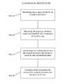
- the fundamental method steps for performing the nerve pathology assessmentsinclude: (a) stimulating one or more nerves with the surgical accessory (e.g. nerve retractor among others); (b) measuring the response of nerves innervated by the stimulation of step (a); (c) determining a relationship between the surgical accessory and the nerve based upon the response measured in step (b); and (d) communicating this relationship to the surgeon in an easy-to-interpret fashion.
- the surgical accessorye.g. nerve retractor among others
- the step of measuring the response of nerves innervated by the stimulation stepmay be performed in any number of suitable fashions, including but not limited to the use of evoked muscle action potential (EMAP) monitoring techniques (that is, measuring the EMG responses of muscle groups associated with a particular nerve).
- EMGevoked muscle action potential
- the measuring stepis preferably accomplished via monitoring or measuring the EMG responses of the muscles innervated by the stimulated nerve(s).
- the step of determining a relationship between the surgical accessory and the nerve based upon the measurement stepmay be performed in any number of suitable fashions depending upon the manner of measuring the response, and may define the relationship in any of a variety of fashions (based on any number of suitable parameters and/or characteristics).
- the relationshipmay be, by way of example only, whether the neurophysiologic response of the nerve has changed over time. Such changes may be quickly determined using a hunting algorithm to determine a stimulation threshold current level at various times during the procedure.
- these parametersmay be augmented with information regarding the pressure being exerted upon a retracted nerve or nerve root.
- the step of communicating the relationship to the usermay also include information about the pressure being exerted upon a retracted nerve or nerve root, such as the retraction duration, the extent of retraction, and/or the resulting pressure.
- FIG. 1is a flow chart illustrating the fundamental steps of the neurophysiology-based surgical system according to the present invention
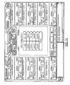
- FIG. 3is a block diagram of the system 10 shown in FIG. 2 ;
- FIGS. 8-9are perspective and side views, respectively, of an exemplary nerve root retractor assembly according to one embodiment of the present invention.
- FIG. 10is a perspective view of an exemplary nerve root retractor forming part of the assembly of FIGS. 8 and 9 , according to one embodiment of the present invention.
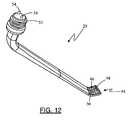
- FIG. 12is a perspective view of an exemplary nerve root retractor including a pressure sensor according to one embodiment of the present invention.
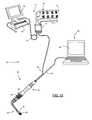
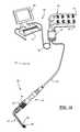
- FIG. 13is a perspective view of the system of FIG. 2 adapted to perform additional pressure sensing functions according to one embodiment of the present invention
- FIG. 14is an exemplary multi-function screen display of the pressure sensing features of the system 10 according to one embodiment of the present invention.
- FIG. 15is an exemplary full screen display of the 2-dimensional pressure mapping feature according to one embodiment of the present invention.
- FIG. 16is an exemplary full screen display of the 3-dimensional pressure mapping feature according to one embodiment of the present invention.
- FIG. 17is an exemplary full screen display of the pressure distribution chart feature according to one embodiment of the present invention.
- FIG. 18is an exemplary full screen display of the pressure vs. time chart feature according to one embodiment of the present invention.
- FIG. 20is an exemplary screen display illustrating one embodiment of the Nerve Retractor mode for performing neural pathology monitoring augmented by pressure monitoring according to one embodiment of the present invention.
- the present inventionis capable of performing a variety of neurophysiologic assessments, and particularly nerve pathology monitoring (via Nerve Retractor mode), by combining neurophysiology monitoring with any of a variety of instruments used in or in preparation for surgery (referred to herein as “surgical accessories”).
- Other assessments performed by the system 10may include one or more of, but not necessarily limited to, neuromuscular pathway status (Twitch Test), pedicle integrity testing (Screw Test), nerve proximity testing during surgical access (Detection), and detection of spontaneous muscle activity (Free Run EMG-which may be conducted alone or in conjunction with any other mode).
- the nerve pathology monitoring of the present inventionmay be augmented by equipping a nerve root retractor 29 with one or more pressure sensing technologies and/or providing an additional system or device for assessing or monitoring the pressure being exerted upon a nerve or nerve root before, during and/or after nerve retraction. It is expressly noted that, although described herein largely in terms of use in spinal surgery, the neuromonitoring system 10 and related methods of the present invention are suitable for use in any number of additional surgical procedures where neurological impairment due to nerve retraction is a concern.
- FIG. 1illustrates the fundamental method steps for performing the nerve pathology assessments (as well as many of the other assessments which may be performed) according to the present invention, namely: (a) stimulating one or more nerves with the surgical accessory (e.g. nerve retactor); (b) measuring the response of nerves innervated by the stimulation of step (a); (c) determining a relationship between the surgical accessory and the nerve based upon the response measured in step (b); and (d) communicating this relationship to the surgeon in an easy-to-interpret fashion.
- the surgical accessorye.g. nerve retactor
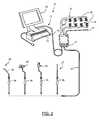
- FIGS. 2-3illustrate, by way of example only, a surgical system 10 provided in accordance with a broad aspect of the present invention.
- the surgical system 10includes a control unit 12 , a patient module 14 , an EMG harness 16 including 8 pairs of EMG electrodes 18 and a return electrode 22 coupled to the patient module 14 , and a host of surgical accessories 24 capable of being coupled to the patient module 14 via one or more accessory cables 26 .
- the surgical accessories 24include (by way of example only) a screw test assembly 27 and a nerve root retractor assembly 28 .
- Other surgical accessories not shown heremay include, but are not necessarily limited to, a K-wire, a sequential dilation access system (e.g.
- an MEP stimulator(not shown) may also be connected to the system 10 .
- the display 30 and/or base 32may contain patient module interface circuitry that commands the stimulation sources, receives digitized signals and other information from the patient module 14 , processes the EMG responses to extract characteristic information for each muscle group, and displays the processed data to the operator via the display 30 .
- the step (a) of stimulating one or more target tissues with the surgical accessory 24is accomplished be coupling one or more surgical accessories 24 equipped with an electrode region(s) to a stimulation source (e.g. the patient module) communicatively linked to the control unit 12 .
- a stimulation sourcee.g. the patient module
- multiple coupling optionsare included with the system 10 to accommodate the variety of surgical accessories and functions performed by the system 10 .
- a stimulation handpiece 36FIG. 1
- the stimulation handpiece 36may include one or more buttons 38 for selectively initiating stimulation according to the selected function.
- the stimulation handpiece 36is reusable and sterilizable.
- an electric coupling devicesuch as, by way of example only, stimulation clip 40 and/or stimulation clip 42 ( FIG. 1 ) may be provided to couple surgical accessories 24 (such as for example, a tap member, access probe, tissue retractor assembly, and/or various cannulae) to the system 10 such that stimulation signals may be transmitted through the tool during use.
- the electric coupling devicemay be used alone or using in conjunction with stimulation handpiece 36 , as is shown.
- Various other connectorsmay also be employed to couple the surgical accessory to the stimulation source, such as for example, a male/female type socket connection and other commonly know electrical connectors.
- EMG electrode placementdepends on a multitude of factors, including for example, the spinal cord level and particular nerves at risk and user preference, among others. In one embodiment (set forth by way of example only), the preferred EMG configuration is described for Lumbar surgery in Table 1, Thoracolumbar surgery in Table 2, and Cervical surgery in Table 3 below:
- the step (c) of determining a relationship between the surgical accessory and the nerve based upon the response measured in step (b)may be performed in any number of suitable fashions depending upon the manner of measuring the response, and may define the relationship in any of a variety of fashions based on any number of suitable parameters and/or characteristics).
- the step of determining a relationshipwithin the context of a nerve pathology assessment, may involve identifying what stimulation current level is required to evoke a significant muscle response (i.e. the relationship between the surgical accessory (and more specifically the stimulation signal emitted from the surgical accessory) and the nerve may be defined as the stimulation threshold current level, described below).
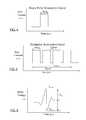
- a significant EMG responseis defined as having a V pp of approximately 100 uV.
- the lowest stimulation signal current, I stim that evokes this threshold voltage (V Thresh )is called I Thresh .
- Finding I threshis useful in making neurophysiologic assessments because it provides a relative indication as to the degree of communication between a stimulation signal and nerve tissue. For example, as the degree of electrical communication between a stimulation signal and a nerve decreases, I thresh will increase. Conversely, as the degree of communication between the stimulation signal and a nerve increases, I thresh will decrease.
- the system 10capitalizes on and enhances the information derived from I thresh by quickly, accurately, and efficiently finding I thresh and comparing the determined value against predetermined safety indicator levels.
- the surgeonmay detect early on any problem or potential problem and then act to avoid and/or mitigate the situation.
- an excessively high I thresh or an increase over a previous I thresh measurement during Nerve Retractor modemay indicate a deterioration of nerve root function caused by excessive and/or prolonged retraction.
- a decrease in I thresh over previous measurementsmay indicate During Screw Test and Detection modes, a low I thresh value may indicate a breach in the pedicle, or the close proximity of a nerve, respectively.
- the system 10may employ a variety of suitable algorithms and techniques which are described in detail in the “NeuroVision Applications,” all of which are incorporated by reference below, as if they were set forth herein in their entireties.
- One exemplary threshold hunting algorithmis described hereafter in only brief detail.
- the threshold hunting algorithmutilizes a bracketing method and a bisection method to find I thresh .
- the bracketing methodfinds a range (bracket) of stimulation currents that must contain I thresh .
- the algorithmdirects stimulation to begin at a predetermined current level (based on the selected function). For each subsequent stimulation, the current level is doubled from the previous current level.
- V threshe.g. 100 uV.
- the initial bracketis successively reduced via the bisection method to a predetermined width. This is accomplished by applying a first bisection stimulation current that bisects (i.e. forms the midpoint of) the initial bracket. If this first bisection stimulation current recruits, the bracket is reduced to the lower half of the initial bracket. If this first bisection stimulation current does not recruit, the bracket is reduced to the upper half of the initial bracket. This process is continued for each successive bracket until I thresh is bracketed by stimulation currents separated by the predetermined width.
- the midpoint of this final bracketmay be defined as I thresh ; however, any value falling within the final bracket may be selected as I thresh without departing from the scope of the present invention.
- stimulationsmay stop after I thresh is determined for the channel possessing the lowest I thresh .
- functionse.g. Screw Tests and Detection
- the hunting algorithmmay employ additional methods allowing it to omit certain stimulations, thereby reducing the number of stimulations and time required to obtain an I thresh value on each channel. I thresh is still found using the bracketing and bisection methods described above, however the algorithm will omit stimulations for which the result is predictable from data previously acquired. When a stimulation signal is omitted, the algorithm proceeds as if the stimulation had taken place.
- the algorithmmay confirm previously obtained I thresh values (e.g. by stimulation at current levels just below and at/or just above I thresh and determining whether the resulting responses are consistent with the previously acquired I thresh value), rather than initiating stimulations from the beginning each time a function is performed.
- the final step (d) of communicating this relationship to the surgeon in an easy-to-interpret fashionmay be accomplished in any number of suitable fashions, including but not limited to the use of visual indicia (such as alpha-numeric characters, light-emitting elements, and/or graphics) and audio communications (such as a speaker element).
- visual indiciasuch as alpha-numeric characters, light-emitting elements, and/or graphics
- audio communicationssuch as a speaker element
- the determined I thresh valuemay be visually displayed as a simple numerical value on display 30 .
- color coded graphicsmay be displayed to indicate the relative safety level indicated by the I thresh (e.g.
- the step of communicating the relationship to the usermay also include information about the pressure being exerted upon a retracted nerve or nerve root, such as the retraction duration, the extent of retraction, and/or the resulting pressure.
- the information shown on the display 30may include at least some of the following components (depending on the active mode) as set forth in Table 1:
- Mode Indicator Graphics and/or nameto indicate the currently active mode (Twitch Test, Free-Run EMG, Basic Screw Test, Dynamic Screw Test, Difference Screw Test, Detection, Nerve Retractor).
- Graphics and/or namemay also be displayed to indicate the instrument in use, such as the dilator, K-wire, retractor blades, screw test instruments, and associated size information, if applicable, of the cannula, with the numeric size. If no instrument is in use, then no indicator is displayed.
- Stimulation BarA graphical stimulation indicator depicting the present stimulation status (i.e. on or off and stimulation current level) Sequence Bar Shows the last seven stimulation results and provides for annotation of results.
- EMG waveformsmay be optionally displayed on screen along with the stimulation results.
- Pressure IndiciaData regarding pressure being exerted upon a retracted nerve or nerve root, such as the duration of retraction, the extent of retraction, and/or the resulting pressure.
- the various functional modes capable of being performed by system 10may include, but is not necessarily limited to, the Twitch Test, Free-run EMG, Basic Screw Test, Difference Screw Test, Dynamic Screw Test, MaXcess® Detection, Nerve Retractor, MEP Auto, MEP manual, and SSEP modes, all of which are described only briefly hereafter.
- the Twitch Test modeis designed to assess the neuromuscular pathway via the so-called “train-of-four test” test to ensure the neuromuscular pathway is free from muscle relaxants prior to performing neurophysiology-based testing, such as bone integrity (e.g. pedicle) testing, nerve detection, and nerve retraction. This is described in greater detail within Int'l Patent App. No.
- PCT/US2005/036089entitled “System and Methods for Assessing the Neuromuscular Pathway Prior to Nerve Testing,” filed Oct. 7, 2005, the entire contents of which is hereby incorporated by reference as if set forth fully herein.
- the Basic Screw Test, Difference Screw Test, and Dynamic Screw Test modesare designed to assess the integrity of bone (e.g. pedicle) during all aspects of pilot hole formation (e.g., via an awl), pilot hole preparation (e.g. via a tap), and screw introduction (during and after). These modes are described in greater detail in Int'l Patent App. No. PCT/US02/35047 entitled “System and Methods for Performing Percutaneous Pedicle Integrity Assessments,” filed on Oct.
- the MaXcess® Detection modeis designed to detect the presence of nerves during the use of the various surgical access instruments of the neuromonitoring system 10 , including the k-wire 62 , dilator 64 , cannula 66 , retractor assembly 70 . This mode is described in greater detail within Int'l Patent App. No PCT/US02/22247, entitled “System and Methods for Determining Nerve Proximity, Direction, and Pathology During Surgery,” filed on Jul.
- the MEP Auto and MEP Manual modesare designed to test the motor pathway to detect potential damage to the spinal cord by stimulating the motor cortex in the brain and recording the resulting EMG response of various muscles in the upper and lower extremities.
- the SSEP functionis designed to test the sensory pathway to detect potential damage to the spinal cord by stimulating peripheral nerves inferior to the target spinal level and recording the action potential from sensors superior to the spinal level.
- the MEP Auto, MEP manual, and SSEP modesare described in greater detail within Int'l Patent App. No. PCT/US2006/003966, entitled “System and Methods for Performing Neurophysiologic Assessments During Spine Surgery,” filed on Feb.
- the Nerve Retractor modeis designed to assess the health or pathology of a nerve before, during, and after retraction of the nerve during a surgical procedure. This mode is described in greater detail within Int'l Patent App. No. PCT/US02/30617, entitled “System and Methods for Performing Surgical Procedures and Assessments,” filed on Sep. 25, 2002, the entire contents of which is hereby incorporated by reference as if set forth fully herein.
- Nerve pathology monitoringas it may be performed by the system 10 during Nerve Retractor mode is described hereafter in more detail.
- the system 10preferably accomplishes neural pathology monitoring via the Nerve Retractor mode, specifically by determining a baseline stimulation threshold (again, stimulation threshold is the value I thresh ) with direct contact between the nerve retractor 29 and the nerve, prior to retraction. Subsequent stimulation thresholds are determined during retraction and they are compared to the baseline threshold. Significant changes in the stimulation threshold may indicate potential trauma to the nerve caused by the retraction and are displayed to the user on the display 30 . An increase in I thresh over time is an indication that the nerve function is deteriorating.
- I threshmay preferably be determined for each channel according to the multi-channel hunting algorithm described above.
- the nerve root retractor assembly 28shown in a preferred embodiment in FIGS. 8-10 , comprises the stimulation handpiece 36 employed with a selectively removable nerve root retractor 29 .
- the nerve root retractor 29has a generally angled orientation relative to the longitudinal axis of the stimulation handpiece 36 .
- the distal end 44is generally curved and includes an arcuate nerve engagement surface 46 equipped with, by way of example only, at least one stimulation electrode 48 .
- the nerve root retractor 29is preferably removable from the stimulation handpiece 36 .
- the stimulation handpiece 36includes a detachable cap member 50 .
- Threads 52are provided on the proximal end of the nerve root retractor 29 to allow a threaded coupling engagement between the stimulation handpiece 36 and the nerve root retractor 29 .
- electrical contacts 54 on the nerve root retractor 29become electrically coupled to the stimulation handpiece 36 such that, upon activation of one or more of the buttons 38 a stimulation current signal will be transmitted from the control unit 12 and/or patient module 14 and delivered to the stimulation electrode(s) 48 on the nerve root retractor 29 for the purpose of performing neural pathology monitoring according to the present invention.
- the nerve root retractor 29is preferably disposable and, as described above, the stimulation handpiece 36 is preferably reusable and sterilizable.
- the nerve root retractor 29is introduced into or near a surgical target site in order to hook and retract a given nerve out of the way.
- the nerve rootmay be stimulated (monopolar or bipolar) before, during, and/or after retraction in order to assess the degree to which such retraction impairs or otherwise degrades nerve function over time.
- the usermay operate one or more buttons 38 of the stimulation handpiece 36 to selectively transmit a stimulation current signal, according to the algorithm described above, from the patient module 14 to the electrode(s) 48 on the engagement surface 46 of the nerve root retractor 29 .
- the system 10can assess whether (and the degree to which) such retraction impairs or adversely affects nerve function over time. With this information, a user may wish to periodically release the nerve root from retraction to allow nerve function to recover, thereby preventing or minimizing the risk of long-term or irreversible nerve impairment. Similarly, an unhealthy nerve may be monitored in the same manner to determine if nerve function improves due to a particular procedure, such as spinal nerve decompression surgery.
- the nerve retraction monitoring feature of the present inventionis best viewed with regard to FIG. 11 .
- the screen display for the Nerve Retractor modemay include any of a variety of indicia capable of communicating parameters associated with the nerve retraction monitoring feature of the present invention to a surgeon, including but not limited to, channel windows containing one or more of the channel number, myotome name, spinal level, baseline I thresh , previous I thresh , current I thresh and the associated waveform, and various selection tabs for one or more of starting baseline stimulation, starting retraction stimulation, stopping stimulation, activating free-run EMG monitoring and adjusting the sensitivity of the free-run EMG, noting the retraction site, mode selection, annotating results, and remote messaging.
- the nerve pathology assessments (Nerve Retractor mode) conducted by the system 10may be further augmented via the use of any number of pressure sensing technologies working in addition to the stimulation based nerve monitoring described above and throughout this disclosure.
- the pressure sensing features contemplated hereinoffer added safety and qualitative assessment features by providing the ability to monitor how much pressure is being applied to a particular nerve during nerve root retraction. This pressure may be a function of, among other factors, the degree of retraction (that is, distance the nerve is moved during retraction) and the duration of retraction. In any case, the pressure resulting on a nerve during retraction—if too high in magnitude and/or too long in duration—may result in neurologic deficit of varying degrees.
- a usermay selectively reduce the degree of retraction (such as by moving the retractor assembly 28 and nerve closer to the “natural” position of the nerve) and/or periodically releaseing the nerve to avoid and/or minimize any resulting neurologic deficit due to retraction.
- the pressure sensing technologiesmay include any number of commercially available and/or publicly known pressure sensing technologies, and/or those later developed.
- the commercially available and/or publicly known pressure sensing technologiesinclude, but are not necessarily limited to, the piezoelectric-based pressure sensing technique shown and described in U.S. Pat. No. 5,769,781 to James Chumbles, the capacitive-based pressure mapping system shown and described in U.S. Pat. No. 5,010,772 to Bourland et. al., the strain gauge-based pressure sensing technology shown and described in U.S. Pat. No. 4,784,150 to Voorhies et. al., the pressure sensitive ink-based technique shown and described in U.S. Pat. No. 5,989,700 to Krivopal, and that shown and described in U.S. Pat. No. 6,272,936 to Oreper et. al.
- Augmenting the nerve pathology monitoring with pressure sensing capabilitiesmay be accomplished in any number of suitable manners, including but not limited to equipping the nerve retractor assembly 28 (and more specifically, one or more of the nerve root retractor 29 , the stimulation handpiece 36 , the distal end 44 , and the nerve engagement surface 46 ) with one or more pressure sensing technologies.
- thismay be done by equipping the nerve engagement surface 46 with a pressure sensor 56 .
- the pressure sensor 56 illustrated in FIG. 12is a capacitive foam grid (comprising any number of suitable grid units) adhered to nerve engagement surface 46 of nerve retractor 29 .
- pressure sensor 56is shown herein having a small number of relatively large grid units, this is done for illustrative purposes. It will be readily understood by those skilled in the art that that any number of grid units and unit sizes may be utilized, and sensor 56 preferably comprises a large number of relatively small grid units to increase precision.
- a data cable(not shown) may be run along the nerve retractor 29 , and is preferably integrated within the interior of nerve retractor 29 , and from there may be connected to the processing unit via cable 58 .
- wireless communicationmay be used to link the pressure sensor and processing unit.
- the processormay be control unit 12 or an additional dedicated processor may be employed for pressure sensing features.
- pressure applied to the capacitive foam gridinduces voltage responses corresponding to the affected grid units.
- the voltage responsesare relayed to the processor which translates the response into one or more of numerical and/or graphical (e.g. color) indicia relating to pressure, which may be displayed to the surgeon.
- a separate system or devicemay be employed for assessing or monitoring the pressure being exerted upon a nerve or nerve root before, during and/or after nerve retraction.
- a separate systemmay supplant (that is, take the place of) and/or augment (that is, serve in along with) the nerve root retractor 29 equipped with pressure sensing capabilities described above.
- the pressure sensing features of the system 10are controlled via a separate processing unit 60 while the EMG based nerve monitoring features are controlled via control unit 12 (as described throughout the description).
- Processing unit 60is preferably a personal workstation or laptop computer (by way of example only) running pressure sensing software designed to interface with the pressure sensor 56 and display pressure data to the user on the processor screen 62 .
- One such software programis the X3 Series software distributed by XSENSORTM Technology Corporation, Calgary Canada.
- processing unit 60is preferably arranged near the control unit 12 such that the surgeon may view nerve pathology data from the display 30 and pressure data from screen 62 at the same time.
- pressure applied to the retracted nervemay be a function of, among other factors, the degree of retraction (that is, distance the nerve is moved during retraction) and the duration of retraction, either of which may result in neurologic deficit of varying degrees.
- FIG. 14illustrates by way of example, a multi-function screen view of the pressure sensing software.
- the multi-function screenmay include (by way of example only) a 2-dimensional (2-D) grid map 64 , a 3-dimensional (3-D) grid map 66 , and a pressure distribution chart 68 , and a pressure vs.
- the tool bar 74 and legend 72may be found on all screen views of the pressure mapping software.
- the tool bar 74allows the user to select between different view screens, among other functions (such as for example, selecting the desired sensor range and precision).
- the legend 74indicates the numerical pressure value associated with a specific color (e.g. in one example red indicates the highest pressure of the selected range, 15.0 PSI in FIG. 14 ).
- FIGS. 15-18illustrate exemplary embodiments of the full screen displays.
- FIG. 15is a full screen display of the 2-D grid map 64 , wherein various colors are used (according to the legend 72 ) to indicate the amount of pressure measured for each grid unit on the sensor 56 .
- a reference marker 76is included which corresponds to a specific corner of the pressure sensor 56 , to help orient the viewer.
- FIG. 16illustrates the full screen display of the 3-D grid map, wherein various colors (according to the legend 72 ) are again used to indicate the amount of pressure measured on the grid units of sensor 56 .
- FIG. 15is a full screen display of the 2-D grid map 64 , wherein various colors are used (according to the legend 72 ) to indicate the amount of pressure measured for each grid unit on the sensor 56 .
- a reference marker 76is included which corresponds to a specific corner of the pressure sensor 56 , to help orient the viewer.
- FIG. 16illustrates the full screen display of the 3-D grid map, wherein various colors
- FIG. 17illustrates the full screen display of the pressure distribution graph 68 , wherein the vertical axis indicates the percentage of grid units at the given moment which are under a measured pressure falling within the pressure intervals on the horizontal axis.
- FIG. 18shows the full screen display of a PvT graph, wherein the maximum pressure measured on sensor 56 is charted against the retraction time.
- the surgeonmay keep be kept aware to the extent which pressure is applied to a nerve throughout retraction, and also the length of time which a nerve is retracted.
- the 2-D and 3-D maps 64 , 66also allow the surgeon to quickly assess not only the extent and duration of the pressure, but also the position, orientation, and center mass of the nerve retractor 29 on the nerve.
- the processor 60may preferably be viewed in real time, however, the processor 60 may also save the data for the entire procedure and the surgeon may go back and view any data from the same procedure at any time.
- the pressure sensing features of the system 10are controlled via the control unit 12 and the pressure features may be fully integrated with the Nerve Retractor mode described above.
- both the pressure sensor 56 and the stimulation electrode 48are communicatively linked to the patient module 14 and pressure data is preferably viewed from within the Nerve Retractor screen display (discussed above with reference to FIG. 11 ).
- An embodiment of the Nerve Retractor screen display when system 10 is augmented with pressure sensing capabilities according to this embodimentis illustrated by way of example only in FIG. 20 .
- the screen displayincludes, among its other features, a pressure selection tab 78 for initiating pressure monitoring (preferably at the same time nerve retraction) begins, a maximum pressure readout 80 , and a timer readout 82 . Selecting the pressure selection tab 78 using the GUI activates the pressure sensor 56 and starts the timer. The running time is displayed to the user in the timer readout 82 . The maximum pressure measured on the sensor 56 is displayed with constant real time updating.
- any of a number of various featuressuch as the 2-D and 3-D grid maps, pressure distribution, and pressure vs. time graph may also be generated and displayed in this embodiment.
- Pressure data measured by the system 10is recorded and saved such that it may be accessed again if necessary. Pressure data may also be included in procedure reports generated by the system 10 such that an accurate record is easily obtained.
- monitoring retraction pressuremay be useful for any number of different body tissues which must be retracted out of the way during surgery.
- itmay be extremely beneficial to monitor retraction pressure on the larynx and/or esophagus which must be retracted during anterior cervical procedure.
- the datamay be transmitted (along with the nerve pathology and other neurophysiologic assessment data) to one or more remote locations and viewable by authorized persons. This may be accomplished by any number of data transmission methods.
- the datamay be transmitted to a remote user via remote monitoring software such as that described in detail in the commonly owned and co-pending U.S. patent application Ser. No. 11/418,589, entitled “System and Methods for Performing and Monitoring Neurophysiologic Assessments,” filed on May 5, 2006, the entire contents of which are incorporated by reference herein as if set forth in its entirety.
- the present inventionmay be implemented using any combination of computer programming software, firmware or hardware.
- the computer programming code(whether software or firmware) according to the invention will typically be stored in one or more machine readable storage mediums such as fixed (hard) drives, diskettes, optical disks, magnetic tape, semiconductor memories such as ROMs, PROMs, etc., thereby making an article of manufacture in accordance with the invention.
- the article of manufacture containing the computer programming codeis used by either executing the code directly from the storage device, by copying the code from the storage device into another storage device such as a hard disk, RAM, etc. or by transmitting the code on a network for remote execution.
- a hard disksuch as a hard disk, RAM, etc.
Landscapes
- Health & Medical Sciences (AREA)
- Life Sciences & Earth Sciences (AREA)
- Medical Informatics (AREA)
- Molecular Biology (AREA)
- Veterinary Medicine (AREA)
- Biophysics (AREA)
- Pathology (AREA)
- Engineering & Computer Science (AREA)
- Biomedical Technology (AREA)
- Heart & Thoracic Surgery (AREA)
- Public Health (AREA)
- Physics & Mathematics (AREA)
- Surgery (AREA)
- Animal Behavior & Ethology (AREA)
- General Health & Medical Sciences (AREA)
- Neurology (AREA)
- Neurosurgery (AREA)
- Nuclear Medicine, Radiotherapy & Molecular Imaging (AREA)
- Radiology & Medical Imaging (AREA)
- Physiology (AREA)
- Measurement And Recording Of Electrical Phenomena And Electrical Characteristics Of The Living Body (AREA)
Abstract
Description
| TABLE 1 |
| Lumbar |
| Color | Channel | Myotome | Nerve | Spinal |
| Red | Right | |||
| 1 | Right Vastus Medialis | Femoral | L2, L3, | |
| Orange | Right | |||
| 2 | Right Tibialis Anterior | Common | L4, L5 | |
| Peroneal | ||||
| Yellow | Right 3 | Right Biceps Femoris | Sciatic | L5, S1, S2 |
| Green | Right 4 | Right Medial Gastroc. | Post Tibial | S1, |
| Blue | Left | |||
| 1 | Left Vastus Medialis | Femoral | L2, L3, | |
| Violet | Left | |||
| 2 | Left Tibialis Anterior | Common | L4, L5 | |
| Peroneal | ||||
| Gray | Left 3 | Left Biceps Femoris | Sciatic | L5, S1, S2 |
| White | Left 4 | Left Medial Gastroc. | Post Tibial | S1, S2 |
| TABLE 2 |
| Thoracolumbar |
| Color | Channel | Myotome | Nerve | Spinal |
| Red | Right | |||
| 1 | Right Abductor | Median | C6, C7, C8, T1 | |
| Pollicis | ||||
| Orange | Right | |||
| 2 | Right Vastus Medialis | Femoral | L2, L3, L4 | |
| Yellow | Right 3 | Right Tibialis Anterior | Common | L4, L5 |
| Peroneal | ||||
| Green | Right 4 | Right Abductor Hallucis | Tibial | L4, L5, |
| Blue | Left | |||
| 1 | Left Abductor | Median | C6, C7, C8, T1 | |
| Pollicis | ||||
| Violet | Left | |||
| 2 | Left Vastus Medialis | Femoral | L2, L3, L4 | |
| Gray | Left 3 | Left Tibialis Anterior | Common | L4, L5 |
| Peroneal | ||||
| White | Left 4 | Left Abductor Hallucis | Tibial | L4, L5, S1 |
| TABLE 3 |
| Cervical |
| Color | Channel | Myotome | Nerve | Spinal |
| Red | Right | |||
| 1 | Right Deltoid | Axilliary | C5, | |
| Orange | Right | |||
| 2 | Right Flexor Carpi | Median | C6, C7, C8 | |
| Radialis | ||||
| Yellow | Right 3 | Right Abductor | Median | C6, C7, C8, T1 |
| Pollicis Brevis | ||||
| Green | Right 4 | Right Abductor Hallucis | Tibial | L4, L5, |
| Blue | Left | |||
| 1 | Left Deltoid | Axillary | C5, | |
| Violet | Left | |||
| 2 | Left Flexor Carpi | Median | C6, C7, C8 | |
| Radialis | ||||
| Gray | Left 3 | Left Abductor Pollicis | Median | C6, C7, C8, T1 |
| Brevis | ||||
| White | Left 4 | Left Abductor Hallucis | Tibial | L4, L5, S1 |
| TABLE 1 | |
| Screen | |
| Component | Description |
| Spine Image | An image of the human body/skeleton showing the electrode placement |
| on the body, with labeled channel number tabs on each side (1-4 on the | |
| left and right). Left and right labels will show the patient orientation. | |
| The channel number tabs may be highlighted or colored depending on | |
| the specific function being performed. | |
| Myotome & Level | A label to indicate the Myotome name and corresponding Spinal |
| Names | Level(s) associated with the channel of interest. |
| Menu | A drop down navigation component for toggling between functions. |
| Display Area | Shows procedure-specific information including stimulation results. |
| Color Indication | Enhances stimulation results with a color display of green, yellow, or |
| red corresponding to the relative safety level determined by the system. | |
| Mode Indicator | Graphics and/or name to indicate the currently active mode (Twitch |
| Test, Free-Run EMG, Basic Screw Test, Dynamic Screw Test, | |
| Difference Screw Test, Detection, Nerve Retractor). In an alternate | |
| embodiment, Graphics and/or name may also be displayed to indicate | |
| the instrument in use, such as the dilator, K-wire, retractor blades, | |
| screw test instruments, and associated size information, if applicable, | |
| of the cannula, with the numeric size. If no instrument is in use, then | |
| no indicator is displayed. | |
| Stimulation Bar | A graphical stimulation indicator depicting the present stimulation |
| status (i.e. on or off and stimulation current level) | |
| Sequence Bar | Shows the last seven stimulation results and provides for annotation of |
| results. | |
| EMG waveforms | EMG waveforms may be optionally displayed on screen along with the |
| stimulation results. | |
| Pressure Indicia | Data regarding pressure being exerted upon a retracted nerve or nerve |
| root, such as the duration of retraction, the extent of retraction, and/or | |
| the resulting pressure. | |
Claims (20)
Priority Applications (3)
| Application Number | Priority Date | Filing Date | Title |
|---|---|---|---|
| US11/490,717US8740783B2 (en) | 2005-07-20 | 2006-07-20 | System and methods for performing neurophysiologic assessments with pressure monitoring |
| US12/817,161US20100317989A1 (en) | 2005-07-20 | 2010-06-16 | Systems and Methods for Performing Neurophysiologic Assesments With Pressure Monitoring |
| US14/294,304US20140288389A1 (en) | 2005-07-20 | 2014-06-03 | Systems and Methods for Performing Neurophysiologic Assessments with Pressure Monitoring |
Applications Claiming Priority (2)
| Application Number | Priority Date | Filing Date | Title |
|---|---|---|---|
| US70130505P | 2005-07-20 | 2005-07-20 | |
| US11/490,717US8740783B2 (en) | 2005-07-20 | 2006-07-20 | System and methods for performing neurophysiologic assessments with pressure monitoring |
Related Child Applications (2)
| Application Number | Title | Priority Date | Filing Date |
|---|---|---|---|
| US12/817,161DivisionUS20100317989A1 (en) | 2005-07-20 | 2010-06-16 | Systems and Methods for Performing Neurophysiologic Assesments With Pressure Monitoring |
| US14/294,304ContinuationUS20140288389A1 (en) | 2005-07-20 | 2014-06-03 | Systems and Methods for Performing Neurophysiologic Assessments with Pressure Monitoring |
Publications (2)
| Publication Number | Publication Date |
|---|---|
| US20070021682A1 US20070021682A1 (en) | 2007-01-25 |
| US8740783B2true US8740783B2 (en) | 2014-06-03 |
Family
ID=37680020
Family Applications (3)
| Application Number | Title | Priority Date | Filing Date |
|---|---|---|---|
| US11/490,717Active2030-01-17US8740783B2 (en) | 2005-07-20 | 2006-07-20 | System and methods for performing neurophysiologic assessments with pressure monitoring |
| US12/817,161AbandonedUS20100317989A1 (en) | 2005-07-20 | 2010-06-16 | Systems and Methods for Performing Neurophysiologic Assesments With Pressure Monitoring |
| US14/294,304AbandonedUS20140288389A1 (en) | 2005-07-20 | 2014-06-03 | Systems and Methods for Performing Neurophysiologic Assessments with Pressure Monitoring |
Family Applications After (2)
| Application Number | Title | Priority Date | Filing Date |
|---|---|---|---|
| US12/817,161AbandonedUS20100317989A1 (en) | 2005-07-20 | 2010-06-16 | Systems and Methods for Performing Neurophysiologic Assesments With Pressure Monitoring |
| US14/294,304AbandonedUS20140288389A1 (en) | 2005-07-20 | 2014-06-03 | Systems and Methods for Performing Neurophysiologic Assessments with Pressure Monitoring |
Country Status (1)
| Country | Link |
|---|---|
| US (3) | US8740783B2 (en) |
Cited By (33)
| Publication number | Priority date | Publication date | Assignee | Title |
|---|---|---|---|---|
| US9037250B2 (en) | 2001-07-11 | 2015-05-19 | Nuvasive, Inc. | System and methods for determining nerve proximity, direction and pathology during surgery |
| US9204871B2 (en) | 2002-10-08 | 2015-12-08 | Nuvasive, Inc. | Surgical access system and related methods |
| US9265493B2 (en) | 2003-09-25 | 2016-02-23 | Nuvasive, Inc. | Surgical access system and related methods |
| US9301743B2 (en) | 2003-01-16 | 2016-04-05 | Nuvasive, Inc. | Surgical access system and related methods |
| US9314152B2 (en) | 2003-09-25 | 2016-04-19 | Nuvasive, Inc. | Surgical access system and related methods |
| US9468405B2 (en) | 2003-02-27 | 2016-10-18 | Nuvasive, Inc. | Surgical access system and related methods |
| US9533155B2 (en) | 2014-08-15 | 2017-01-03 | Axonics Modulation Technologies, Inc. | Methods for determining neurostimulation electrode configurations based on neural localization |
| US9555246B2 (en) | 2014-08-15 | 2017-01-31 | Axonics Modulation Technologies, Inc. | Electromyographic lead positioning and stimulation titration in a nerve stimulation system for treatment of overactive bladder |
| US9743853B2 (en) | 1999-11-24 | 2017-08-29 | Nuvasive, Inc. | Electromyography system |
| US9750490B2 (en) | 2002-06-26 | 2017-09-05 | Nuvasive, Inc. | Surgical access system and related methods |
| US10016600B2 (en) | 2013-05-30 | 2018-07-10 | Neurostim Solutions, Llc | Topical neurological stimulation |
| US10092762B2 (en) | 2014-08-15 | 2018-10-09 | Axonics Modulation Technologies, Inc. | Integrated electromyographic clinician programmer for use with an implantable neurostimulator |
| US10507120B2 (en) | 2001-09-25 | 2019-12-17 | Nuvasive, Inc. | Systems and methods for performing surgical procedures and assessments |
| US10953225B2 (en) | 2017-11-07 | 2021-03-23 | Neurostim Oab, Inc. | Non-invasive nerve activator with adaptive circuit |
| US10959860B2 (en) | 2008-12-26 | 2021-03-30 | Pantheon Spinal, Llc | Method of retroperitoneal lateral insertion of spinal implants |
| US11026627B2 (en) | 2013-03-15 | 2021-06-08 | Cadwell Laboratories, Inc. | Surgical instruments for determining a location of a nerve during a procedure |
| US11077301B2 (en) | 2015-02-21 | 2021-08-03 | NeurostimOAB, Inc. | Topical nerve stimulator and sensor for bladder control |
| US11177610B2 (en) | 2017-01-23 | 2021-11-16 | Cadwell Laboratories, ino. | Neuromonitoring connection system |
| US11229789B2 (en) | 2013-05-30 | 2022-01-25 | Neurostim Oab, Inc. | Neuro activator with controller |
| US11253182B2 (en) | 2018-05-04 | 2022-02-22 | Cadwell Laboratories, Inc. | Apparatus and method for polyphasic multi-output constant-current and constant-voltage neurophysiological stimulation |
| US11443649B2 (en) | 2018-06-29 | 2022-09-13 | Cadwell Laboratories, Inc. | Neurophysiological monitoring training simulator |
| US11439829B2 (en) | 2019-05-24 | 2022-09-13 | Axonics, Inc. | Clinician programmer methods and systems for maintaining target operating temperatures |
| US11458311B2 (en) | 2019-06-26 | 2022-10-04 | Neurostim Technologies Llc | Non-invasive nerve activator patch with adaptive circuit |
| US11701047B2 (en) | 2017-06-16 | 2023-07-18 | Alphatec Spine, Inc. | Systems, methods, and devices for detecting the threshold of nerve-muscle response using variable frequency of stimulation |
| US11730958B2 (en) | 2019-12-16 | 2023-08-22 | Neurostim Solutions, Llc | Non-invasive nerve activator with boosted charge delivery |
| US11848090B2 (en) | 2019-05-24 | 2023-12-19 | Axonics, Inc. | Trainer for a neurostimulator programmer and associated methods of use with a neurostimulation system |
| US11963784B2 (en) | 2013-11-07 | 2024-04-23 | Safeop Surgical, Inc. | Systems and methods for detecting nerve function |
| US11963775B2 (en) | 2017-03-22 | 2024-04-23 | Safeop Surgical, Inc. | Medical systems and methods for detecting changes in electrophysiological evoked potentials |
| US11986321B2 (en) | 2016-09-22 | 2024-05-21 | Safeop Surgical, Inc. | System and method for detecting and removing periodic non-physiological artifact from evoked potentials |
| US11992339B2 (en) | 2018-05-04 | 2024-05-28 | Cadwell Laboratories, Inc. | Systems and methods for dynamic neurophysiological stimulation |
| US12048567B2 (en) | 2015-05-04 | 2024-07-30 | Safeop Surgical, Inc. | System, method, and computer algorithm for measuring, displaying, and accurately detecting changes in electrophysiological evoked potentials |
| US12082944B2 (en) | 2018-10-31 | 2024-09-10 | Stryker Corporation | System and method for monitoring nerve activity within a trachea of a patient |
| US12343069B2 (en) | 2017-02-01 | 2025-07-01 | Avent, Inc. | EMG guidance for probe placement, nearby tissue preservation, and lesion confirmation |
Families Citing this family (44)
| Publication number | Priority date | Publication date | Assignee | Title |
|---|---|---|---|---|
| US8313430B1 (en) | 2006-01-11 | 2012-11-20 | Nuvasive, Inc. | Surgical access system and related methods |
| US9795367B1 (en)* | 2003-10-17 | 2017-10-24 | Nuvasive, Inc. | Surgical access system and related methods |
| WO2007038290A2 (en) | 2005-09-22 | 2007-04-05 | Nuvasive, Inc. | Multi-channel stimulation threshold detection algorithm for use in neurophysiology monitoring |
| WO2008124079A1 (en)* | 2007-04-03 | 2008-10-16 | Nuvasive, Inc. | Neurophysiologic monitoring system |
| BRPI0818608A2 (en) | 2007-10-05 | 2015-04-22 | Synthes Gmbh | Sequential directional dilatation system for dilating from a nerve of a patient's anatomy, and method for forming an access opening through a psoas muscle to a patient's spine using a dilatation system |
| US7811138B2 (en)* | 2008-02-29 | 2010-10-12 | Pioneer Surgical Technology, Inc. | Electrical connector for surgical systems |
| US8137285B1 (en)* | 2008-08-26 | 2012-03-20 | Rhythmlink International, Llc | Monopolar stimulation probe system |
| EP3231365B1 (en)* | 2008-10-15 | 2025-01-22 | Nuvasive, Inc. | Neurophysiologic monitoring system |
| US9084551B2 (en) | 2008-12-08 | 2015-07-21 | Medtronic Xomed, Inc. | Method and system for monitoring a nerve |
| EP2429388A2 (en)* | 2009-05-11 | 2012-03-21 | Timothy Taylor Davis | Neurologic monitoring system and method |
| US20110230785A1 (en)* | 2010-03-16 | 2011-09-22 | ProNerve, LLC | Somatosensory Evoked Potential (SSEP) Automated Alert System |
| US9392953B1 (en)* | 2010-09-17 | 2016-07-19 | Nuvasive, Inc. | Neurophysiologic monitoring |
| WO2012040206A1 (en) | 2010-09-20 | 2012-03-29 | Synthes Usa, Llc | Spinal access retractor |
| US9155503B2 (en)* | 2010-10-27 | 2015-10-13 | Cadwell Labs | Apparatus, system, and method for mapping the location of a nerve |
| US9808232B2 (en) | 2011-11-01 | 2017-11-07 | DePuy Synthes Products, Inc. | Dilation system |
| US9265490B2 (en) | 2012-04-16 | 2016-02-23 | DePuy Synthes Products, Inc. | Detachable dilator blade |
| US11259737B2 (en) | 2012-11-06 | 2022-03-01 | Nuvasive, Inc. | Systems and methods for performing neurophysiologic monitoring during spine surgery |
| US11877860B2 (en) | 2012-11-06 | 2024-01-23 | Nuvasive, Inc. | Systems and methods for performing neurophysiologic monitoring during spine surgery |
| US9757067B1 (en) | 2012-11-09 | 2017-09-12 | Nuvasive, Inc. | Systems and methods for performing neurophysiologic monitoring during spine surgery |
| US9757072B1 (en) | 2013-02-11 | 2017-09-12 | Nuvasive, Inc. | Waveform marker placement algorithm for use in neurophysiologic monitoring |
| FR3010628B1 (en) | 2013-09-18 | 2015-10-16 | Medicrea International | METHOD FOR REALIZING THE IDEAL CURVATURE OF A ROD OF A VERTEBRAL OSTEOSYNTHESIS EQUIPMENT FOR STRENGTHENING THE VERTEBRAL COLUMN OF A PATIENT |
| FR3012030B1 (en) | 2013-10-18 | 2015-12-25 | Medicrea International | METHOD FOR REALIZING THE IDEAL CURVATURE OF A ROD OF A VERTEBRAL OSTEOSYNTHESIS EQUIPMENT FOR STRENGTHENING THE VERTEBRAL COLUMN OF A PATIENT |
| US10258228B2 (en) | 2014-08-08 | 2019-04-16 | K2M, Inc. | Retraction devices, systems, and methods for minimally invasive spinal surgery |
| US10420480B1 (en) | 2014-09-16 | 2019-09-24 | Nuvasive, Inc. | Systems and methods for performing neurophysiologic monitoring |
| US10433793B1 (en) | 2015-03-27 | 2019-10-08 | Cadwell Laboratories, Inc. | Methods and systems for simultaneous review of brain activity and physical manifestations of users |
| US10456211B2 (en) | 2015-11-04 | 2019-10-29 | Medicrea International | Methods and apparatus for spinal reconstructive surgery and measuring spinal length and intervertebral spacing, tension and rotation |
| US9801582B2 (en)* | 2015-11-12 | 2017-10-31 | King Saud University | Thigh adhesion quantitative measurement system |
| US11241297B2 (en) | 2016-12-12 | 2022-02-08 | Cadwell Laboratories, Inc. | System and method for high density electrode management |
| WO2018109556A1 (en) | 2016-12-12 | 2018-06-21 | Medicrea International | Systems and methods for patient-specific spinal implants |
| EP3612122B1 (en) | 2017-04-21 | 2023-12-20 | Medicrea International | A system for developing one or more patient-specific spinal implants |
| US10918422B2 (en) | 2017-12-01 | 2021-02-16 | Medicrea International | Method and apparatus for inhibiting proximal junctional failure |
| US11517239B2 (en) | 2018-04-05 | 2022-12-06 | Cadwell Laboratories, Inc. | Systems and methods for processing and displaying electromyographic signals |
| US11596337B2 (en) | 2018-04-24 | 2023-03-07 | Cadwell Laboratories, Inc | Methods and systems for operating an intraoperative neurophysiological monitoring system in conjunction with electrocautery procedures |
| US11185684B2 (en) | 2018-09-18 | 2021-11-30 | Cadwell Laboratories, Inc. | Minimally invasive two-dimensional grid electrode |
| US11517245B2 (en) | 2018-10-30 | 2022-12-06 | Cadwell Laboratories, Inc. | Method and system for data synchronization |
| US11471087B2 (en) | 2018-11-09 | 2022-10-18 | Cadwell Laboratories, Inc. | Integrity verification system for testing high channel count neuromonitoring recording equipment |
| US11317841B2 (en) | 2018-11-14 | 2022-05-03 | Cadwell Laboratories, Inc. | Method and system for electrode verification |
| US11529107B2 (en) | 2018-11-27 | 2022-12-20 | Cadwell Laboratories, Inc. | Methods for automatic generation of EEG montages |
| US11128076B2 (en) | 2019-01-21 | 2021-09-21 | Cadwell Laboratories, Inc. | Connector receptacle |
| US11877801B2 (en) | 2019-04-02 | 2024-01-23 | Medicrea International | Systems, methods, and devices for developing patient-specific spinal implants, treatments, operations, and/or procedures |
| US11944385B2 (en) | 2019-04-02 | 2024-04-02 | Medicrea International | Systems and methods for medical image analysis |
| US11925417B2 (en) | 2019-04-02 | 2024-03-12 | Medicrea International | Systems, methods, and devices for developing patient-specific spinal implants, treatments, operations, and/or procedures |
| US11769251B2 (en) | 2019-12-26 | 2023-09-26 | Medicrea International | Systems and methods for medical image analysis |
| US12318144B2 (en) | 2021-06-23 | 2025-06-03 | Medicrea International SA | Systems and methods for planning a patient-specific spinal correction |
Citations (193)
| Publication number | Priority date | Publication date | Assignee | Title |
|---|---|---|---|---|
| US972983A (en) | 1909-05-17 | 1910-10-18 | Lester R Lantz | Dilator. |
| US1328624A (en) | 1917-08-13 | 1920-01-20 | Frank B Graham | Dilator |
| US1548184A (en) | 1923-04-11 | 1925-08-04 | Will J Cameron | Holder and control for pulp testers |
| US2704064A (en) | 1952-09-10 | 1955-03-15 | Meditron Company | Neurosurgical stimulator |
| US2736002A (en) | 1956-02-21 | oriel | ||
| US2808826A (en) | 1956-01-19 | 1957-10-08 | Teca Corp | Electro-diagnostic apparatus and a circuit therefor |
| US3364929A (en) | 1964-12-21 | 1968-01-23 | Burroughs Wellcome Co | Method for administering muscle relaxant drug |
| US3664329A (en) | 1970-03-09 | 1972-05-23 | Concept | Nerve locator/stimulator |
| US3682162A (en) | 1968-12-13 | 1972-08-08 | Wellcome Found | Combined electrode and hypodermic syringe needle |
| US3785368A (en) | 1971-08-23 | 1974-01-15 | Carthy T Mc | Abnormal nerve pressure locus detector and method |
| US3830226A (en) | 1973-06-15 | 1974-08-20 | Concept | Variable output nerve locator |
| US3957036A (en) | 1975-02-03 | 1976-05-18 | Baylor College Of Medicine | Method and apparatus for recording activity in intact nerves |
| US4099519A (en) | 1977-01-14 | 1978-07-11 | Warren Fred E | Diagnostic device |
| US4164214A (en) | 1977-07-25 | 1979-08-14 | The Regents Of The University Of California | Method and apparatus for measuring the sensitivity of teeth |
| US4207897A (en) | 1976-07-21 | 1980-06-17 | Spembly Limited | Cryosurgical probe |
| US4224949A (en) | 1977-11-17 | 1980-09-30 | Cornell Research Foundation, Inc. | Method and electrical resistance probe for detection of estrus in bovine |
| US4226228A (en) | 1978-11-02 | 1980-10-07 | Shin Hee J | Multiple joint retractor with light |
| US4235242A (en) | 1979-04-02 | 1980-11-25 | Med General, Inc. | Electronic circuit permitting simultaneous use of stimulating and monitoring equipment |
| US4285347A (en) | 1979-07-25 | 1981-08-25 | Cordis Corporation | Stabilized directional neural electrode lead |
| US4291705A (en) | 1979-09-10 | 1981-09-29 | The Regents Of The University Of California | Neuromuscular block monitor |
| US4461300A (en) | 1982-01-18 | 1984-07-24 | Sutter Biomedical, Inc. | Bone and tissue healing device including a special electrode assembly and method |
| US4515168A (en) | 1983-07-22 | 1985-05-07 | Chester Martin H | Clamp-on nerve stimulator and locator |
| US4519403A (en) | 1983-04-29 | 1985-05-28 | Medtronic, Inc. | Balloon lead and inflator |
| US4545374A (en) | 1982-09-03 | 1985-10-08 | Jacobson Robert E | Method and instruments for performing a percutaneous lumbar diskectomy |
| US4561445A (en) | 1983-05-25 | 1985-12-31 | Joseph J. Berke | Elongated needle electrode and method of making same |
| US4562832A (en) | 1984-01-21 | 1986-01-07 | Wilder Joseph R | Medical instrument and light pipe illumination assembly |
| US4573448A (en) | 1983-10-05 | 1986-03-04 | Pilling Co. | Method for decompressing herniated intervertebral discs |
| US4592369A (en) | 1982-07-12 | 1986-06-03 | National Research Development Corp. | Method and apparatus for use in temporal analysis of waveforms |
| US4595018A (en) | 1983-06-10 | 1986-06-17 | Instrumentarium Corp. | Method of further developing the measuring of a neuro-muscular junction |
| US4616660A (en) | 1984-12-10 | 1986-10-14 | Suncoast Medical Manufacturing, Inc. | Variable alternating current output nerve locator/stimulator |
| US4633889A (en) | 1984-12-12 | 1987-01-06 | Andrew Talalla | Stimulation of cauda-equina spinal nerves |
| US4658835A (en) | 1985-07-25 | 1987-04-21 | Cordis Corporation | Neural stimulating lead with fixation canopy formation |
| US4744371A (en) | 1987-04-27 | 1988-05-17 | Cordis Leads, Inc. | Multi-conductor lead assembly for temporary use |
| US4759377A (en) | 1986-11-26 | 1988-07-26 | Regents Of The University Of Minnesota | Apparatus and method for mechanical stimulation of nerves |
| US4784150A (en) | 1986-11-04 | 1988-11-15 | Research Corporation | Surgical retractor and blood flow monitor |
| US4807642A (en) | 1985-08-16 | 1989-02-28 | Brown David A | Electromyographic repetitive strain injury monitor |
| US4892105A (en) | 1986-03-28 | 1990-01-09 | The Cleveland Clinic Foundation | Electrical stimulus probe |
| US4926865A (en) | 1987-10-01 | 1990-05-22 | Oman Paul S | Microcomputer-based nerve and muscle stimulator |
| US4962766A (en) | 1989-07-19 | 1990-10-16 | Herzon Garrett D | Nerve locator and stimulator |
| US4964411A (en) | 1989-07-13 | 1990-10-23 | Empi, Inc. | Evoked EMG signal processing |
| US5007902A (en) | 1988-03-09 | 1991-04-16 | B. Braun Melsungen Ag | Catheter set for plexus anesthesia |
| US5058602A (en) | 1988-09-30 | 1991-10-22 | Brody Stanley R | Paraspinal electromyography scanning |
| US5081990A (en) | 1990-05-11 | 1992-01-21 | New York University | Catheter for spinal epidural injection of drugs and measurement of evoked potentials |
| US5092344A (en) | 1990-11-19 | 1992-03-03 | Lee Tzium Shou | Remote indicator for stimulator |
| US5125406A (en) | 1989-11-29 | 1992-06-30 | Eet Limited Partnership (Del) | Electrode endotracheal tube |
| US5127403A (en) | 1988-07-05 | 1992-07-07 | Cardiac Control Systems, Inc. | Pacemaker catheter utilizing bipolar electrodes spaced in accordance to the length of a heart depolarization signal |
| US5161533A (en) | 1991-09-19 | 1992-11-10 | Xomed-Treace Inc. | Break-apart needle electrode system for monitoring facial EMG |
| US5196015A (en) | 1992-04-30 | 1993-03-23 | Neubardt Seth L | Procedure for spinal pedicle screw insertion |
| US5201325A (en)* | 1989-09-01 | 1993-04-13 | Andronic Devices Ltd. | Advanced surgical retractor |
| USRE34390E (en) | 1980-12-31 | 1993-09-28 | Nicolet Instrument Corporation | Apparatus and method for topographic display of multichannel EEG data |
| US5255691A (en) | 1991-11-13 | 1993-10-26 | Medtronic, Inc. | Percutaneous epidural lead introducing system and method |
| US5282468A (en) | 1990-06-07 | 1994-02-01 | Medtronic, Inc. | Implantable neural electrode |
| US5284153A (en) | 1992-04-14 | 1994-02-08 | Brigham And Women's Hospital | Method for locating a nerve and for protecting nerves from injury during surgery |
| US5299563A (en) | 1992-07-31 | 1994-04-05 | Seton Joseph Z | Method of using a surgical retractor |
| US5312417A (en) | 1992-07-29 | 1994-05-17 | Wilk Peter J | Laparoscopic cannula assembly and associated method |
| US5313956A (en) | 1990-12-04 | 1994-05-24 | Dorsograf Ab | Apparatus for measuring the transport time of nerve signals |
| US5313962A (en) | 1991-10-18 | 1994-05-24 | Obenchain Theodore G | Method of performing laparoscopic lumbar discectomy |
| US5327902A (en) | 1993-05-14 | 1994-07-12 | Lemmen Roger D | Apparatus for use in nerve conduction studies |
| US5333618A (en) | 1993-06-30 | 1994-08-02 | Gregory Lekhtman | Portable self-contained instrument for the measurement of nerve resistance of a patient |
| US5375067A (en) | 1992-12-11 | 1994-12-20 | Nicolet Instrument Corporation | Method and apparatus for adjustment of acquisition parameters in a data acquisition system such as a digital oscilloscope |
| US5383876A (en) | 1992-11-13 | 1995-01-24 | American Cardiac Ablation Co., Inc. | Fluid cooled electrosurgical probe for cutting and cauterizing tissue |
| US5474558A (en) | 1992-04-30 | 1995-12-12 | Neubardt; Seth L. | Procedure and system for spinal pedicle screw insertion |
| US5480440A (en) | 1991-08-15 | 1996-01-02 | Smith & Nephew Richards, Inc. | Open surgical technique for vertebral fixation with subcutaneous fixators positioned between the skin and the lumbar fascia of a patient |
| US5482038A (en) | 1994-06-28 | 1996-01-09 | Cadwell Industries, Inc. | Needle electrode assembly |
| US5484437A (en) | 1988-06-13 | 1996-01-16 | Michelson; Gary K. | Apparatus and method of inserting spinal implants |
| US5540235A (en) | 1994-06-30 | 1996-07-30 | Wilson; John R. | Adaptor for neurophysiological monitoring with a personal computer |
| US5549656A (en) | 1993-08-16 | 1996-08-27 | Med Serve Group, Inc. | Combination neuromuscular stimulator and electromyograph system |
| US5560372A (en) | 1994-02-02 | 1996-10-01 | Cory; Philip C. | Non-invasive, peripheral nerve mapping device and method of use |
| US5566678A (en) | 1993-09-10 | 1996-10-22 | Cadwell Industries, Inc. | Digital EEG noise synthesizer |
| US5569248A (en) | 1992-03-17 | 1996-10-29 | Danek Medical, Inc. | Apparatus for subcutaneous suprafascial pedicular internal fixation |
| US5579781A (en) | 1994-10-13 | 1996-12-03 | Cooke; Thomas H. | Wireless transmitter for needle electrodes as used in electromyography |
| US5593429A (en) | 1994-06-28 | 1997-01-14 | Cadwell Industries, Inc. | Needle electrode with depth of penetration limiter |
| US5599279A (en) | 1994-03-16 | 1997-02-04 | Gus J. Slotman | Surgical instruments and method useful for endoscopic spinal procedures |
| US5601608A (en) | 1995-02-02 | 1997-02-11 | Pacesetter, Inc. | Methods and apparatus for applying charge-balanced antiarrhythmia shocks |
| EP0759307A2 (en) | 1995-08-22 | 1997-02-26 | STERIMED Medizinprodukte GmbH | Puncturing and/or catheterizing device for locating nerves |
| US5630813A (en) | 1994-12-08 | 1997-05-20 | Kieturakis; Maciej J. | Electro-cauterizing dissector and method for facilitating breast implant procedure |
| US5671752A (en) | 1995-03-31 | 1997-09-30 | Universite De Montreal/The Royal Insitution For The Advancement Of Learning (Mcgill University) | Diaphragm electromyography analysis method and system |
| US5707359A (en) | 1995-11-14 | 1998-01-13 | Bufalini; Bruno | Expanding trocar assembly |
| US5711307A (en) | 1995-04-13 | 1998-01-27 | Liberty Mutual Insurance Company | Method and apparatus for detecting myoelectric activity from the surface of the skin |
| US5728046A (en) | 1995-06-23 | 1998-03-17 | Aesculap Ag | Surgical retractor |
| US5741253A (en) | 1988-06-13 | 1998-04-21 | Michelson; Gary Karlin | Method for inserting spinal implants |
| US5759159A (en) | 1996-09-25 | 1998-06-02 | Ormco Corporation | Method and apparatus for apical detection with complex impedance measurement |
| US5769781A (en) | 1995-11-13 | 1998-06-23 | Chappuis; James L. | Protector retractor |
| US5772661A (en) | 1988-06-13 | 1998-06-30 | Michelson; Gary Karlin | Methods and instrumentation for the surgical correction of human thoracic and lumbar spinal disease from the antero-lateral aspect of the spine |
| US5775331A (en) | 1995-06-07 | 1998-07-07 | Uromed Corporation | Apparatus and method for locating a nerve |
| US5776144A (en) | 1996-05-10 | 1998-07-07 | Implex Gmbh Spezialhorgerate | Device for positioning and fixing of therapeutic, surgical, or diagnostic instruments |
| US5779642A (en) | 1996-01-16 | 1998-07-14 | Nightengale; Christopher | Interrogation device and method |
| US5785658A (en) | 1992-09-14 | 1998-07-28 | Sexant Medical Corporation | In vivo tissue analysis methods and apparatus |
| US5797854A (en) | 1995-08-01 | 1998-08-25 | Hedgecock; James L. | Method and apparatus for testing and measuring current perception threshold and motor nerve junction performance |
| US5814073A (en) | 1996-12-13 | 1998-09-29 | Bonutti; Peter M. | Method and apparatus for positioning a suture anchor |
| US5830151A (en) | 1995-04-10 | 1998-11-03 | Innovative Design Associates | Apparatus for locating and anesthetizing peripheral nerves a method therefor |
| US5851191A (en) | 1997-07-01 | 1998-12-22 | Neurometrix, Inc. | Apparatus and methods for assessment of neuromuscular function |
| US5853373A (en) | 1996-08-05 | 1998-12-29 | Becton, Dickinson And Company | Bi-level charge pulse apparatus to facilitate nerve location during peripheral nerve block procedures |
| US5862314A (en) | 1996-11-01 | 1999-01-19 | Micron Electronics, Inc. | System and method for remapping defective memory locations |
| US5860973A (en) | 1995-02-27 | 1999-01-19 | Michelson; Gary Karlin | Translateral spinal implant |
| US5872314A (en) | 1997-07-25 | 1999-02-16 | Clinton; Robert P. | Method and apparatus for measuring characteristics of meat |
| US5888196A (en) | 1990-03-02 | 1999-03-30 | General Surgical Innovations, Inc. | Mechanically expandable arthroscopic retractors |
| US5902231A (en) | 1996-03-22 | 1999-05-11 | Sdgi Holdings, Inc. | Devices and methods for percutaneous surgery |
| DE29908259U1 (en) | 1999-05-07 | 1999-07-15 | Aesculap AG & Co. KG, 78532 Tuttlingen | Rotating surgical tool |
| US5928139A (en) | 1998-04-24 | 1999-07-27 | Koros; Tibor B. | Retractor with adjustable length blades and light pipe guides |
| US5928158A (en) | 1997-03-25 | 1999-07-27 | Aristides; Arellano | Medical instrument with nerve sensor |
| US6004262A (en) | 1998-05-04 | 1999-12-21 | Ad-Tech Medical Instrument Corp. | Visually-positioned electrical monitoring apparatus |
| US6011985A (en) | 1994-04-01 | 2000-01-04 | University Of South Florida | Medical diagnostic instrument using light-to-frequency converter |
| US6027456A (en) | 1998-07-10 | 2000-02-22 | Advanced Neuromodulation Systems, Inc. | Apparatus and method for positioning spinal cord stimulation leads |
| US6038477A (en) | 1998-12-23 | 2000-03-14 | Axon Engineering, Inc. | Multiple channel nerve stimulator with channel isolation |
| US6038469A (en) | 1994-10-07 | 2000-03-14 | Ortivus Ab | Myocardial ischemia and infarction analysis and monitoring method and apparatus |
| US6050992A (en) | 1997-05-19 | 2000-04-18 | Radiotherapeutics Corporation | Apparatus and method for treating tissue with multiple electrodes |
| US6074343A (en) | 1999-04-16 | 2000-06-13 | Nathanson; Michael | Surgical tissue retractor |
| US6104957A (en) | 1998-08-21 | 2000-08-15 | Alo; Kenneth M. | Epidural nerve root stimulation with lead placement method |
| US6104960A (en) | 1998-07-13 | 2000-08-15 | Medtronic, Inc. | System and method for providing medical electrical stimulation to a portion of the nervous system |
| US6119068A (en) | 1996-12-27 | 2000-09-12 | Kannonji; Michihiro | Rear-end collision alarming device and method linked to speed control device of a vehicle |
| US6120503A (en) | 1994-03-28 | 2000-09-19 | Michelson; Gary Karlin | Apparatus instrumentation, and method for spinal fixation |
| US6128576A (en) | 1998-07-13 | 2000-10-03 | Mitsubishi Denki Kabushiki Kaisha | Obstruction detecting apparatus |
| US6126660A (en) | 1998-07-29 | 2000-10-03 | Sofamor Danek Holdings, Inc. | Spinal compression and distraction devices and surgical methods |
| US6132386A (en) | 1997-07-01 | 2000-10-17 | Neurometrix, Inc. | Methods for the assessment of neuromuscular function by F-wave latency |
| US6132387A (en) | 1997-07-01 | 2000-10-17 | Neurometrix, Inc. | Neuromuscular electrode |
| US6135965A (en) | 1996-12-02 | 2000-10-24 | Board Of Regents, The University Of Texas System | Spectroscopic detection of cervical pre-cancer using radial basis function networks |
| US6139493A (en) | 1998-07-08 | 2000-10-31 | Koros; Tibor B. | Retractor with adjustable length blades and light pipe guides |
| US6139545A (en) | 1998-09-09 | 2000-10-31 | Vidaderm | Systems and methods for ablating discrete motor nerve regions |
| US6146335A (en) | 1997-07-01 | 2000-11-14 | Neurometrix, Inc. | Apparatus for methods for the assessment of neuromuscular function of the lower extremity |
| US6161047A (en) | 1998-04-30 | 2000-12-12 | Medtronic Inc. | Apparatus and method for expanding a stimulation lead body in situ |
| US6181961B1 (en) | 1997-12-16 | 2001-01-30 | Richard L. Prass | Method and apparatus for an automatic setup of a multi-channel nerve integrity monitoring system |
| FR2796846A1 (en) | 1999-07-30 | 2001-02-02 | Mohamed Zouheir Naja | Thoraco-abdominal or pelvic anaesthesia apparatus comprises needle and electrode linked to electrical power source, extension, guide tube and catheter |
| US6206826B1 (en) | 1997-12-18 | 2001-03-27 | Sdgi Holdings, Inc. | Devices and methods for percutaneous surgery |
| US6210324B1 (en) | 1996-12-05 | 2001-04-03 | Waldix Teixeira Reno | Lever retractor for surgical flaps with handle |
| US6224549B1 (en) | 1999-04-20 | 2001-05-01 | Nicolet Biomedical, Inc. | Medical signal monitoring and display |
| US6259945B1 (en)* | 1999-04-30 | 2001-07-10 | Uromed Corporation | Method and device for locating a nerve |
| US6266558B1 (en) | 1998-12-01 | 2001-07-24 | Neurometrix, Inc. | Apparatus and method for nerve conduction measurements with automatic setting of stimulus intensity |
| US6273905B1 (en) | 1999-03-23 | 2001-08-14 | Jackson Streeter | Method for treating spinal cord transection |
| US6292701B1 (en) | 1998-08-12 | 2001-09-18 | Medtronic Xomed, Inc. | Bipolar electrical stimulus probe with planar electrodes |
| FR2795624B1 (en) | 1999-07-01 | 2001-09-28 | Vanacker Gerard | METHOD FOR DRILLING THE VERTEBRAL PEDICLE, PARTICULARLY FOR THE PLACEMENT OF A PEDICULAR SCREW, AN INSTRUMENT FOR THE IMPLEMENTATION OF SUCH A PROCESS |
| US6306100B1 (en) | 1997-12-16 | 2001-10-23 | Richard L. Prass | Intraoperative neurophysiological monitoring system |
| US6312392B1 (en) | 2000-04-06 | 2001-11-06 | Garrett D. Herzon | Bipolar handheld nerve locator and evaluator |
| US20010039949A1 (en) | 1999-05-04 | 2001-11-15 | Loubser Paul G. | Superglottic and peri-laryngeal apparatus for supraglottic airway insertion |
| US6334068B1 (en) | 1999-09-14 | 2001-12-25 | Medtronic Xomed, Inc. | Intraoperative neuroelectrophysiological monitor |
| US20010056280A1 (en) | 1992-01-07 | 2001-12-27 | Underwood Ronald A. | Systems and methods for electrosurgical spine surgery |
| US20020007129A1 (en) | 2000-06-08 | 2002-01-17 | Marino James F. | Nerve movement and status detection system and method |
| US6346078B1 (en) | 2000-12-04 | 2002-02-12 | Alan G. Ellman | Eyelid retractor for electrosurgery |
| US6348058B1 (en) | 1997-12-12 | 2002-02-19 | Surgical Navigation Technologies, Inc. | Image guided spinal surgery guide, system, and method for use thereof |
| US6393325B1 (en) | 1999-01-07 | 2002-05-21 | Advanced Bionics Corporation | Directional programming for implantable electrode arrays |
| US20020072686A1 (en) | 2000-05-18 | 2002-06-13 | Nuvasive, Inc. | Tissue discrimination and applications in medical procedures |
| US6425901B1 (en) | 1995-12-07 | 2002-07-30 | Loma Linda University Medical Center | Vascular wound closure system |
| US6451015B1 (en) | 1998-11-18 | 2002-09-17 | Sherwood Services Ag | Method and system for menu-driven two-dimensional display lesion generator |
| US6466817B1 (en) | 1999-11-24 | 2002-10-15 | Nuvasive, Inc. | Nerve proximity and status detection system and method |
| US20020161415A1 (en) | 2001-04-26 | 2002-10-31 | Ehud Cohen | Actuation and control of limbs through motor nerve stimulation |
| US20020193843A1 (en) | 2000-09-26 | 2002-12-19 | Hill Michael R.S. | Method and system for spinal cord stimulation prior to and during a medical procedure |
| US6507755B1 (en) | 1998-12-01 | 2003-01-14 | Neurometrix, Inc. | Apparatus and method for stimulating human tissue |
| US20030032966A1 (en) | 1999-10-20 | 2003-02-13 | Foley Kevin T. | Methods and instrumentation for distraction of a disc space |
| US6546271B1 (en)* | 1999-10-01 | 2003-04-08 | Bioscience, Inc. | Vascular reconstruction |
| US20030078618A1 (en) | 2001-10-19 | 2003-04-24 | Fey Kate E. | System and method for removing implanted devices |
| US6564078B1 (en) | 1998-12-23 | 2003-05-13 | Nuvasive, Inc. | Nerve surveillance cannula systems |
| US20030105503A1 (en) | 2001-06-08 | 2003-06-05 | Nuvasive, Inc. | Relative nerve movement and status detection system and method |
| US6579244B2 (en) | 2001-10-24 | 2003-06-17 | Cutting Edge Surgical, Inc. | Intraosteal ultrasound during surgical implantation |
| US6582441B1 (en) | 2000-02-24 | 2003-06-24 | Advanced Bionics Corporation | Surgical insertion tool |
| US6585638B1 (en) | 1998-09-18 | 2003-07-01 | Hidehiro Yamamoto | Endoscope power supplying appliance |
| US6618626B2 (en) | 2001-01-16 | 2003-09-09 | Hs West Investments, Llc | Apparatus and methods for protecting the axillary nerve during thermal capsullorhaphy |
| WO2004012809A8 (en) | 2002-08-06 | 2004-04-01 | Neopraxis Pty Ltd | A method and system for inserting an electrode |
| US6719692B2 (en) | 1999-05-07 | 2004-04-13 | Aesculap Ag & Co. Kg | Rotating surgical tool |
| US6730021B2 (en) | 2001-11-07 | 2004-05-04 | Computer Motion, Inc. | Tissue spreader with force measurement, force indication or force limitation |
| US6770074B2 (en) | 1988-06-13 | 2004-08-03 | Gary Karlin Michelson | Apparatus for use in inserting spinal implants |
| US20040199084A1 (en) | 1999-11-24 | 2004-10-07 | Nuvasive, Inc. | Electromyography system |
| US20040225228A1 (en)* | 2003-05-08 | 2004-11-11 | Ferree Bret A. | Neurophysiological apparatus and procedures |
| US6819956B2 (en) | 1998-08-05 | 2004-11-16 | Dilorenzo Daniel J. | Optimal method and apparatus for neural modulation for the treatment of neurological disease, particularly movement disorders |
| US20050004593A1 (en) | 2001-10-30 | 2005-01-06 | Depuy Spine, Inc. | Non cannulated dilators |
| US20050004623A1 (en) | 2002-10-30 | 2005-01-06 | Patrick Miles | System and methods for performing percutaneous pedicle integrity assessments |
| US6847849B2 (en) | 2000-11-15 | 2005-01-25 | Medtronic, Inc. | Minimally invasive apparatus for implanting a sacral stimulation lead |
| US6855105B2 (en) | 2001-07-11 | 2005-02-15 | Jackson, Iii Avery M. | Endoscopic pedicle probe |
| US20050075578A1 (en) | 2001-09-25 | 2005-04-07 | James Gharib | System and methods for performing surgical procedures and assessments |
| US20050080418A1 (en) | 2001-10-30 | 2005-04-14 | Simonson Robert E. | Instruments and methods for minimally invasive spine surgery |
| US20050119660A1 (en) | 2002-02-11 | 2005-06-02 | Maurice Bourlion | Device for monitoring penetration into anatomical members |
| US6902569B2 (en) | 2000-08-17 | 2005-06-07 | Image-Guided Neurologics, Inc. | Trajectory guide with instrument immobilizer |
| US6916294B2 (en) | 2002-07-09 | 2005-07-12 | George Washington University | Brain retraction sensor |
| WO2005013805A3 (en) | 2003-08-05 | 2005-07-28 | Nuvasive Inc | Systemand methods for performing dynamic pedicle integrity assessments |
| US6926728B2 (en) | 2001-07-18 | 2005-08-09 | St. Francis Medical Technologies, Inc. | Curved dilator and method |
| US6929606B2 (en) | 2001-01-29 | 2005-08-16 | Depuy Spine, Inc. | Retractor and method for spinal pedicle screw placement |
| US20050182454A1 (en) | 2001-07-11 | 2005-08-18 | Nuvasive, Inc. | System and methods for determining nerve proximity, direction, and pathology during surgery |
| US20050256582A1 (en) | 1999-10-08 | 2005-11-17 | Ferree Bret A | Spinal implants, including devices that reduce pressure on the annulus fibrosis |
| US20060052828A1 (en) | 2004-09-08 | 2006-03-09 | Kim Daniel H | Methods for stimulating a nerve root ganglion |
| US20060069315A1 (en) | 2003-09-25 | 2006-03-30 | Patrick Miles | Surgical access system and related methods |
| US7079883B2 (en) | 1998-12-23 | 2006-07-18 | Nuvaslve, Inc. | Nerve surveillance cannulae systems |
| US7089059B1 (en) | 2000-11-03 | 2006-08-08 | Pless Benjamin D | Predicting susceptibility to neurological dysfunction based on measured neural electrophysiology |
| WO2006084193A9 (en) | 2005-02-02 | 2006-10-12 | Nuvasive Inc | System and methods for performing neurophysiologic assessments during spine surgery |
| US7153279B2 (en) | 2002-07-09 | 2006-12-26 | George Washington University | Brain retraction sensor |
| US20070016097A1 (en) | 2003-01-15 | 2007-01-18 | Nuvasive, Inc. | System and methods for determining nerve direction to a surgical instrument |
| US7258688B1 (en) | 2002-04-16 | 2007-08-21 | Baylis Medical Company Inc. | Computerized electrical signal generator |
| US7294127B2 (en) | 2002-03-05 | 2007-11-13 | Baylis Medical Company Inc. | Electrosurgical tissue treatment method |
| US7306563B2 (en)* | 2002-03-02 | 2007-12-11 | Huang Herb H | Pulse diagnostic system |
| US7310546B2 (en) | 2001-11-06 | 2007-12-18 | Prass Richard L | Artifact detection electrode |
| US20080015612A1 (en) | 2002-09-04 | 2008-01-17 | Urmey William F | Positioning system for a nerve stimulator needle |
| US20080039914A1 (en) | 2000-11-24 | 2008-02-14 | Nervonix, Inc. | Needle with depth determination capability and method of use |
| US20080058606A1 (en) | 2002-10-08 | 2008-03-06 | Nuvasive, Inc. | Surgical access system and related methods |
| USD621041S1 (en) | 2007-06-22 | 2010-08-03 | Vioptix Inc. | Portion of nerve root retractor with sensor |
| US7775974B2 (en) | 2004-07-23 | 2010-08-17 | North Carolina State University | Force-determining retraction device and associated method |
Family Cites Families (11)
| Publication number | Priority date | Publication date | Assignee | Title |
|---|---|---|---|---|
| GB8411480D0 (en)* | 1984-05-04 | 1984-06-13 | Raychem Corp | Sensor array |
| US5085226A (en)* | 1990-05-30 | 1992-02-04 | Trustees Of Boston University | Force monitoring apparatus for back muscles |
| US5163328A (en)* | 1990-08-06 | 1992-11-17 | Colin Electronics Co., Ltd. | Miniature pressure sensor and pressure sensor arrays |
| US5253656A (en)* | 1991-05-23 | 1993-10-19 | Rincoe Richard G | Apparatus and method for monitoring contact pressure between body parts and contact surfaces |
| US6500210B1 (en)* | 1992-09-08 | 2002-12-31 | Seattle Systems, Inc. | System and method for providing a sense of feel in a prosthetic or sensory impaired limb |
| US5924984A (en)* | 1997-01-30 | 1999-07-20 | University Of Iowa Research Foundation | Anorectal probe apparatus having at least one muscular activity sensor |
| US6511427B1 (en)* | 2000-03-10 | 2003-01-28 | Acuson Corporation | System and method for assessing body-tissue properties using a medical ultrasound transducer probe with a body-tissue parameter measurement mechanism |
| US6543299B2 (en)* | 2001-06-26 | 2003-04-08 | Geoffrey L. Taylor | Pressure measurement sensor with piezoresistive thread lattice |
| AU2003232111B2 (en)* | 2002-05-09 | 2008-10-02 | Covidien Lp | Endoscopic organ retractor and method of using the same |
| US20040068203A1 (en)* | 2002-10-03 | 2004-04-08 | Scimed Life Systems, Inc. | Sensing pressure |
| AU2004216229B2 (en)* | 2003-02-21 | 2010-12-09 | Electro-Cat, Llc | System and method for measuring cross-sectional areas and pressure gradients in luminal organs |
- 2006
- 2006-07-20USUS11/490,717patent/US8740783B2/enactiveActive
- 2010
- 2010-06-16USUS12/817,161patent/US20100317989A1/ennot_activeAbandoned
- 2014
- 2014-06-03USUS14/294,304patent/US20140288389A1/ennot_activeAbandoned
Patent Citations (215)
| Publication number | Priority date | Publication date | Assignee | Title |
|---|---|---|---|---|
| US2736002A (en) | 1956-02-21 | oriel | ||
| US972983A (en) | 1909-05-17 | 1910-10-18 | Lester R Lantz | Dilator. |
| US1328624A (en) | 1917-08-13 | 1920-01-20 | Frank B Graham | Dilator |
| US1548184A (en) | 1923-04-11 | 1925-08-04 | Will J Cameron | Holder and control for pulp testers |
| US2704064A (en) | 1952-09-10 | 1955-03-15 | Meditron Company | Neurosurgical stimulator |
| US2808826A (en) | 1956-01-19 | 1957-10-08 | Teca Corp | Electro-diagnostic apparatus and a circuit therefor |
| US3364929A (en) | 1964-12-21 | 1968-01-23 | Burroughs Wellcome Co | Method for administering muscle relaxant drug |
| US3682162A (en) | 1968-12-13 | 1972-08-08 | Wellcome Found | Combined electrode and hypodermic syringe needle |
| US3664329A (en) | 1970-03-09 | 1972-05-23 | Concept | Nerve locator/stimulator |
| US3785368A (en) | 1971-08-23 | 1974-01-15 | Carthy T Mc | Abnormal nerve pressure locus detector and method |
| US3830226A (en) | 1973-06-15 | 1974-08-20 | Concept | Variable output nerve locator |
| US3957036A (en) | 1975-02-03 | 1976-05-18 | Baylor College Of Medicine | Method and apparatus for recording activity in intact nerves |
| US4207897A (en) | 1976-07-21 | 1980-06-17 | Spembly Limited | Cryosurgical probe |
| US4099519A (en) | 1977-01-14 | 1978-07-11 | Warren Fred E | Diagnostic device |
| US4164214A (en) | 1977-07-25 | 1979-08-14 | The Regents Of The University Of California | Method and apparatus for measuring the sensitivity of teeth |
| US4224949A (en) | 1977-11-17 | 1980-09-30 | Cornell Research Foundation, Inc. | Method and electrical resistance probe for detection of estrus in bovine |
| US4226228A (en) | 1978-11-02 | 1980-10-07 | Shin Hee J | Multiple joint retractor with light |
| US4235242A (en) | 1979-04-02 | 1980-11-25 | Med General, Inc. | Electronic circuit permitting simultaneous use of stimulating and monitoring equipment |
| US4285347A (en) | 1979-07-25 | 1981-08-25 | Cordis Corporation | Stabilized directional neural electrode lead |
| US4291705A (en) | 1979-09-10 | 1981-09-29 | The Regents Of The University Of California | Neuromuscular block monitor |
| USRE34390E (en) | 1980-12-31 | 1993-09-28 | Nicolet Instrument Corporation | Apparatus and method for topographic display of multichannel EEG data |
| US4461300A (en) | 1982-01-18 | 1984-07-24 | Sutter Biomedical, Inc. | Bone and tissue healing device including a special electrode assembly and method |
| US4592369A (en) | 1982-07-12 | 1986-06-03 | National Research Development Corp. | Method and apparatus for use in temporal analysis of waveforms |
| US4545374A (en) | 1982-09-03 | 1985-10-08 | Jacobson Robert E | Method and instruments for performing a percutaneous lumbar diskectomy |
| US4519403A (en) | 1983-04-29 | 1985-05-28 | Medtronic, Inc. | Balloon lead and inflator |
| US4561445A (en) | 1983-05-25 | 1985-12-31 | Joseph J. Berke | Elongated needle electrode and method of making same |
| US4595018A (en) | 1983-06-10 | 1986-06-17 | Instrumentarium Corp. | Method of further developing the measuring of a neuro-muscular junction |
| US4515168A (en) | 1983-07-22 | 1985-05-07 | Chester Martin H | Clamp-on nerve stimulator and locator |
| US4573448A (en) | 1983-10-05 | 1986-03-04 | Pilling Co. | Method for decompressing herniated intervertebral discs |
| US4562832A (en) | 1984-01-21 | 1986-01-07 | Wilder Joseph R | Medical instrument and light pipe illumination assembly |
| US4616660A (en) | 1984-12-10 | 1986-10-14 | Suncoast Medical Manufacturing, Inc. | Variable alternating current output nerve locator/stimulator |
| US4633889A (en) | 1984-12-12 | 1987-01-06 | Andrew Talalla | Stimulation of cauda-equina spinal nerves |
| US4658835A (en) | 1985-07-25 | 1987-04-21 | Cordis Corporation | Neural stimulating lead with fixation canopy formation |
| US4807642A (en) | 1985-08-16 | 1989-02-28 | Brown David A | Electromyographic repetitive strain injury monitor |
| US4892105A (en) | 1986-03-28 | 1990-01-09 | The Cleveland Clinic Foundation | Electrical stimulus probe |
| US4784150A (en) | 1986-11-04 | 1988-11-15 | Research Corporation | Surgical retractor and blood flow monitor |
| US4759377A (en) | 1986-11-26 | 1988-07-26 | Regents Of The University Of Minnesota | Apparatus and method for mechanical stimulation of nerves |
| US4744371A (en) | 1987-04-27 | 1988-05-17 | Cordis Leads, Inc. | Multi-conductor lead assembly for temporary use |
| US4926865A (en) | 1987-10-01 | 1990-05-22 | Oman Paul S | Microcomputer-based nerve and muscle stimulator |
| US5007902A (en) | 1988-03-09 | 1991-04-16 | B. Braun Melsungen Ag | Catheter set for plexus anesthesia |
| US6770074B2 (en) | 1988-06-13 | 2004-08-03 | Gary Karlin Michelson | Apparatus for use in inserting spinal implants |
| US5772661A (en) | 1988-06-13 | 1998-06-30 | Michelson; Gary Karlin | Methods and instrumentation for the surgical correction of human thoracic and lumbar spinal disease from the antero-lateral aspect of the spine |
| US5741253A (en) | 1988-06-13 | 1998-04-21 | Michelson; Gary Karlin | Method for inserting spinal implants |
| US5484437A (en) | 1988-06-13 | 1996-01-16 | Michelson; Gary K. | Apparatus and method of inserting spinal implants |
| US5127403A (en) | 1988-07-05 | 1992-07-07 | Cardiac Control Systems, Inc. | Pacemaker catheter utilizing bipolar electrodes spaced in accordance to the length of a heart depolarization signal |
| US5058602A (en) | 1988-09-30 | 1991-10-22 | Brody Stanley R | Paraspinal electromyography scanning |
| US4964411A (en) | 1989-07-13 | 1990-10-23 | Empi, Inc. | Evoked EMG signal processing |
| US4962766A (en) | 1989-07-19 | 1990-10-16 | Herzon Garrett D | Nerve locator and stimulator |
| US5201325A (en)* | 1989-09-01 | 1993-04-13 | Andronic Devices Ltd. | Advanced surgical retractor |
| US5125406A (en) | 1989-11-29 | 1992-06-30 | Eet Limited Partnership (Del) | Electrode endotracheal tube |
| US5888196A (en) | 1990-03-02 | 1999-03-30 | General Surgical Innovations, Inc. | Mechanically expandable arthroscopic retractors |
| US5081990A (en) | 1990-05-11 | 1992-01-21 | New York University | Catheter for spinal epidural injection of drugs and measurement of evoked potentials |
| US5282468A (en) | 1990-06-07 | 1994-02-01 | Medtronic, Inc. | Implantable neural electrode |
| US5092344A (en) | 1990-11-19 | 1992-03-03 | Lee Tzium Shou | Remote indicator for stimulator |
| US5313956A (en) | 1990-12-04 | 1994-05-24 | Dorsograf Ab | Apparatus for measuring the transport time of nerve signals |
| US5480440A (en) | 1991-08-15 | 1996-01-02 | Smith & Nephew Richards, Inc. | Open surgical technique for vertebral fixation with subcutaneous fixators positioned between the skin and the lumbar fascia of a patient |
| US5161533A (en) | 1991-09-19 | 1992-11-10 | Xomed-Treace Inc. | Break-apart needle electrode system for monitoring facial EMG |
| US5313962A (en) | 1991-10-18 | 1994-05-24 | Obenchain Theodore G | Method of performing laparoscopic lumbar discectomy |
| US5255691A (en) | 1991-11-13 | 1993-10-26 | Medtronic, Inc. | Percutaneous epidural lead introducing system and method |
| US20010056280A1 (en) | 1992-01-07 | 2001-12-27 | Underwood Ronald A. | Systems and methods for electrosurgical spine surgery |
| US5569248A (en) | 1992-03-17 | 1996-10-29 | Danek Medical, Inc. | Apparatus for subcutaneous suprafascial pedicular internal fixation |
| US5284154A (en) | 1992-04-14 | 1994-02-08 | Brigham And Women's Hospital | Apparatus for locating a nerve and for protecting nerves from injury during surgery |
| US5284153A (en) | 1992-04-14 | 1994-02-08 | Brigham And Women's Hospital | Method for locating a nerve and for protecting nerves from injury during surgery |
| US5474558A (en) | 1992-04-30 | 1995-12-12 | Neubardt; Seth L. | Procedure and system for spinal pedicle screw insertion |
| US5196015A (en) | 1992-04-30 | 1993-03-23 | Neubardt Seth L | Procedure for spinal pedicle screw insertion |
| US5312417A (en) | 1992-07-29 | 1994-05-17 | Wilk Peter J | Laparoscopic cannula assembly and associated method |
| US5299563A (en) | 1992-07-31 | 1994-04-05 | Seton Joseph Z | Method of using a surgical retractor |
| US5785658A (en) | 1992-09-14 | 1998-07-28 | Sexant Medical Corporation | In vivo tissue analysis methods and apparatus |
| US5383876A (en) | 1992-11-13 | 1995-01-24 | American Cardiac Ablation Co., Inc. | Fluid cooled electrosurgical probe for cutting and cauterizing tissue |
| US5375067A (en) | 1992-12-11 | 1994-12-20 | Nicolet Instrument Corporation | Method and apparatus for adjustment of acquisition parameters in a data acquisition system such as a digital oscilloscope |
| US5327902A (en) | 1993-05-14 | 1994-07-12 | Lemmen Roger D | Apparatus for use in nerve conduction studies |
| US5333618A (en) | 1993-06-30 | 1994-08-02 | Gregory Lekhtman | Portable self-contained instrument for the measurement of nerve resistance of a patient |
| US5549656A (en) | 1993-08-16 | 1996-08-27 | Med Serve Group, Inc. | Combination neuromuscular stimulator and electromyograph system |
| US5566678B1 (en) | 1993-09-10 | 1999-11-30 | Cadwell Ind Inc | Digital eeg noise synthesizer |
| US5566678A (en) | 1993-09-10 | 1996-10-22 | Cadwell Industries, Inc. | Digital EEG noise synthesizer |
| US5560372A (en) | 1994-02-02 | 1996-10-01 | Cory; Philip C. | Non-invasive, peripheral nerve mapping device and method of use |
| US5599279A (en) | 1994-03-16 | 1997-02-04 | Gus J. Slotman | Surgical instruments and method useful for endoscopic spinal procedures |
| US6120503A (en) | 1994-03-28 | 2000-09-19 | Michelson; Gary Karlin | Apparatus instrumentation, and method for spinal fixation |
| US6011985A (en) | 1994-04-01 | 2000-01-04 | University Of South Florida | Medical diagnostic instrument using light-to-frequency converter |
| US5593429A (en) | 1994-06-28 | 1997-01-14 | Cadwell Industries, Inc. | Needle electrode with depth of penetration limiter |
| US5482038A (en) | 1994-06-28 | 1996-01-09 | Cadwell Industries, Inc. | Needle electrode assembly |
| US5540235A (en) | 1994-06-30 | 1996-07-30 | Wilson; John R. | Adaptor for neurophysiological monitoring with a personal computer |
| US6038469A (en) | 1994-10-07 | 2000-03-14 | Ortivus Ab | Myocardial ischemia and infarction analysis and monitoring method and apparatus |
| US5579781A (en) | 1994-10-13 | 1996-12-03 | Cooke; Thomas H. | Wireless transmitter for needle electrodes as used in electromyography |
| US5630813A (en) | 1994-12-08 | 1997-05-20 | Kieturakis; Maciej J. | Electro-cauterizing dissector and method for facilitating breast implant procedure |
| US5601608A (en) | 1995-02-02 | 1997-02-11 | Pacesetter, Inc. | Methods and apparatus for applying charge-balanced antiarrhythmia shocks |
| US5860973A (en) | 1995-02-27 | 1999-01-19 | Michelson; Gary Karlin | Translateral spinal implant |
| US5671752A (en) | 1995-03-31 | 1997-09-30 | Universite De Montreal/The Royal Insitution For The Advancement Of Learning (Mcgill University) | Diaphragm electromyography analysis method and system |
| US5830151A (en) | 1995-04-10 | 1998-11-03 | Innovative Design Associates | Apparatus for locating and anesthetizing peripheral nerves a method therefor |
| US5711307A (en) | 1995-04-13 | 1998-01-27 | Liberty Mutual Insurance Company | Method and apparatus for detecting myoelectric activity from the surface of the skin |
| US5775331A (en) | 1995-06-07 | 1998-07-07 | Uromed Corporation | Apparatus and method for locating a nerve |
| US5728046A (en) | 1995-06-23 | 1998-03-17 | Aesculap Ag | Surgical retractor |
| US5797854A (en) | 1995-08-01 | 1998-08-25 | Hedgecock; James L. | Method and apparatus for testing and measuring current perception threshold and motor nerve junction performance |
| EP0759307A2 (en) | 1995-08-22 | 1997-02-26 | STERIMED Medizinprodukte GmbH | Puncturing and/or catheterizing device for locating nerves |
| US5769781A (en) | 1995-11-13 | 1998-06-23 | Chappuis; James L. | Protector retractor |
| US5707359A (en) | 1995-11-14 | 1998-01-13 | Bufalini; Bruno | Expanding trocar assembly |
| US6425901B1 (en) | 1995-12-07 | 2002-07-30 | Loma Linda University Medical Center | Vascular wound closure system |
| US5779642A (en) | 1996-01-16 | 1998-07-14 | Nightengale; Christopher | Interrogation device and method |
| US5885219A (en) | 1996-01-16 | 1999-03-23 | Nightengale; Christopher | Interrogation device and method |
| US6425859B1 (en) | 1996-03-22 | 2002-07-30 | Sdgi Holdings, Inc. | Cannula and a retractor for percutaneous surgery |
| US5902231A (en) | 1996-03-22 | 1999-05-11 | Sdgi Holdings, Inc. | Devices and methods for percutaneous surgery |
| US5776144A (en) | 1996-05-10 | 1998-07-07 | Implex Gmbh Spezialhorgerate | Device for positioning and fixing of therapeutic, surgical, or diagnostic instruments |
| US5853373A (en) | 1996-08-05 | 1998-12-29 | Becton, Dickinson And Company | Bi-level charge pulse apparatus to facilitate nerve location during peripheral nerve block procedures |
| US6325764B1 (en) | 1996-08-05 | 2001-12-04 | Becton, Dickinson And Company | Bi-level charge pulse apparatus to facilitate nerve location during peripheral nerve block procedures |
| US5759159A (en) | 1996-09-25 | 1998-06-02 | Ormco Corporation | Method and apparatus for apical detection with complex impedance measurement |
| US5862314A (en) | 1996-11-01 | 1999-01-19 | Micron Electronics, Inc. | System and method for remapping defective memory locations |
| US6135965A (en) | 1996-12-02 | 2000-10-24 | Board Of Regents, The University Of Texas System | Spectroscopic detection of cervical pre-cancer using radial basis function networks |
| US6210324B1 (en) | 1996-12-05 | 2001-04-03 | Waldix Teixeira Reno | Lever retractor for surgical flaps with handle |
| US5814073A (en) | 1996-12-13 | 1998-09-29 | Bonutti; Peter M. | Method and apparatus for positioning a suture anchor |
| US6119068A (en) | 1996-12-27 | 2000-09-12 | Kannonji; Michihiro | Rear-end collision alarming device and method linked to speed control device of a vehicle |
| US5928158A (en) | 1997-03-25 | 1999-07-27 | Aristides; Arellano | Medical instrument with nerve sensor |
| US6050992A (en) | 1997-05-19 | 2000-04-18 | Radiotherapeutics Corporation | Apparatus and method for treating tissue with multiple electrodes |
| US5976094A (en) | 1997-07-01 | 1999-11-02 | Neurometrix, Inc. | Apparatus and methods for assessment of neuromuscular function |
| US5851191A (en) | 1997-07-01 | 1998-12-22 | Neurometrix, Inc. | Apparatus and methods for assessment of neuromuscular function |
| US6132386A (en) | 1997-07-01 | 2000-10-17 | Neurometrix, Inc. | Methods for the assessment of neuromuscular function by F-wave latency |
| US6132387A (en) | 1997-07-01 | 2000-10-17 | Neurometrix, Inc. | Neuromuscular electrode |
| US6146335A (en) | 1997-07-01 | 2000-11-14 | Neurometrix, Inc. | Apparatus for methods for the assessment of neuromuscular function of the lower extremity |
| US5872314A (en) | 1997-07-25 | 1999-02-16 | Clinton; Robert P. | Method and apparatus for measuring characteristics of meat |
| US6348058B1 (en) | 1997-12-12 | 2002-02-19 | Surgical Navigation Technologies, Inc. | Image guided spinal surgery guide, system, and method for use thereof |
| US6306100B1 (en) | 1997-12-16 | 2001-10-23 | Richard L. Prass | Intraoperative neurophysiological monitoring system |
| US6181961B1 (en) | 1997-12-16 | 2001-01-30 | Richard L. Prass | Method and apparatus for an automatic setup of a multi-channel nerve integrity monitoring system |
| US6206826B1 (en) | 1997-12-18 | 2001-03-27 | Sdgi Holdings, Inc. | Devices and methods for percutaneous surgery |
| US5928139A (en) | 1998-04-24 | 1999-07-27 | Koros; Tibor B. | Retractor with adjustable length blades and light pipe guides |
| US6161047A (en) | 1998-04-30 | 2000-12-12 | Medtronic Inc. | Apparatus and method for expanding a stimulation lead body in situ |
| US6004262A (en) | 1998-05-04 | 1999-12-21 | Ad-Tech Medical Instrument Corp. | Visually-positioned electrical monitoring apparatus |
| US6139493A (en) | 1998-07-08 | 2000-10-31 | Koros; Tibor B. | Retractor with adjustable length blades and light pipe guides |
| US6027456A (en) | 1998-07-10 | 2000-02-22 | Advanced Neuromodulation Systems, Inc. | Apparatus and method for positioning spinal cord stimulation leads |
| US6104960A (en) | 1998-07-13 | 2000-08-15 | Medtronic, Inc. | System and method for providing medical electrical stimulation to a portion of the nervous system |
| EP0972538A3 (en) | 1998-07-13 | 2000-12-20 | Medtronic, Inc. | System for providing medical electrical stimulation to a portion of the nervous system |
| US6128576A (en) | 1998-07-13 | 2000-10-03 | Mitsubishi Denki Kabushiki Kaisha | Obstruction detecting apparatus |
| US6126660A (en) | 1998-07-29 | 2000-10-03 | Sofamor Danek Holdings, Inc. | Spinal compression and distraction devices and surgical methods |
| US6819956B2 (en) | 1998-08-05 | 2004-11-16 | Dilorenzo Daniel J. | Optimal method and apparatus for neural modulation for the treatment of neurological disease, particularly movement disorders |
| US6292701B1 (en) | 1998-08-12 | 2001-09-18 | Medtronic Xomed, Inc. | Bipolar electrical stimulus probe with planar electrodes |
| US6104957A (en) | 1998-08-21 | 2000-08-15 | Alo; Kenneth M. | Epidural nerve root stimulation with lead placement method |
| US6139545A (en) | 1998-09-09 | 2000-10-31 | Vidaderm | Systems and methods for ablating discrete motor nerve regions |
| US6585638B1 (en) | 1998-09-18 | 2003-07-01 | Hidehiro Yamamoto | Endoscope power supplying appliance |
| US6451015B1 (en) | 1998-11-18 | 2002-09-17 | Sherwood Services Ag | Method and system for menu-driven two-dimensional display lesion generator |
| US6266558B1 (en) | 1998-12-01 | 2001-07-24 | Neurometrix, Inc. | Apparatus and method for nerve conduction measurements with automatic setting of stimulus intensity |
| US6507755B1 (en) | 1998-12-01 | 2003-01-14 | Neurometrix, Inc. | Apparatus and method for stimulating human tissue |
| US6564078B1 (en) | 1998-12-23 | 2003-05-13 | Nuvasive, Inc. | Nerve surveillance cannula systems |
| US7079883B2 (en) | 1998-12-23 | 2006-07-18 | Nuvaslve, Inc. | Nerve surveillance cannulae systems |
| US6038477A (en) | 1998-12-23 | 2000-03-14 | Axon Engineering, Inc. | Multiple channel nerve stimulator with channel isolation |
| US6393325B1 (en) | 1999-01-07 | 2002-05-21 | Advanced Bionics Corporation | Directional programming for implantable electrode arrays |
| US6273905B1 (en) | 1999-03-23 | 2001-08-14 | Jackson Streeter | Method for treating spinal cord transection |
| US6074343A (en) | 1999-04-16 | 2000-06-13 | Nathanson; Michael | Surgical tissue retractor |
| US6224549B1 (en) | 1999-04-20 | 2001-05-01 | Nicolet Biomedical, Inc. | Medical signal monitoring and display |
| US6259945B1 (en)* | 1999-04-30 | 2001-07-10 | Uromed Corporation | Method and device for locating a nerve |
| US20010039949A1 (en) | 1999-05-04 | 2001-11-15 | Loubser Paul G. | Superglottic and peri-laryngeal apparatus for supraglottic airway insertion |
| US6719692B2 (en) | 1999-05-07 | 2004-04-13 | Aesculap Ag & Co. Kg | Rotating surgical tool |
| DE29908259U1 (en) | 1999-05-07 | 1999-07-15 | Aesculap AG & Co. KG, 78532 Tuttlingen | Rotating surgical tool |
| US6796985B2 (en) | 1999-07-01 | 2004-09-28 | Spinevision S.A. | Method for drilling bone, in particular for setting a pedicle screw, equipment, instrument and control device for implementing said method |
| FR2795624B1 (en) | 1999-07-01 | 2001-09-28 | Vanacker Gerard | METHOD FOR DRILLING THE VERTEBRAL PEDICLE, PARTICULARLY FOR THE PLACEMENT OF A PEDICULAR SCREW, AN INSTRUMENT FOR THE IMPLEMENTATION OF SUCH A PROCESS |
| FR2796846A1 (en) | 1999-07-30 | 2001-02-02 | Mohamed Zouheir Naja | Thoraco-abdominal or pelvic anaesthesia apparatus comprises needle and electrode linked to electrical power source, extension, guide tube and catheter |
| US6334068B1 (en) | 1999-09-14 | 2001-12-25 | Medtronic Xomed, Inc. | Intraoperative neuroelectrophysiological monitor |
| US6546271B1 (en)* | 1999-10-01 | 2003-04-08 | Bioscience, Inc. | Vascular reconstruction |
| US20050256582A1 (en) | 1999-10-08 | 2005-11-17 | Ferree Bret A | Spinal implants, including devices that reduce pressure on the annulus fibrosis |
| US20030032966A1 (en) | 1999-10-20 | 2003-02-13 | Foley Kevin T. | Methods and instrumentation for distraction of a disc space |
| US7177677B2 (en) | 1999-11-24 | 2007-02-13 | Nuvasive, Inc. | Nerve proximity and status detection system and method |
| US20070293782A1 (en) | 1999-11-24 | 2007-12-20 | Nu Vasive, Inc. | Electromyography system |
| US20080064977A1 (en) | 1999-11-24 | 2008-03-13 | Nuvasive, Inc. | Electromyography system |
| US20080065178A1 (en) | 1999-11-24 | 2008-03-13 | Nuvasive, Inc. | Electromyography system |
| US20080064976A1 (en) | 1999-11-24 | 2008-03-13 | Nuvasive, Inc. | Electromyography system |
| US20040199084A1 (en) | 1999-11-24 | 2004-10-07 | Nuvasive, Inc. | Electromyography system |
| US6466817B1 (en) | 1999-11-24 | 2002-10-15 | Nuvasive, Inc. | Nerve proximity and status detection system and method |
| US20080071191A1 (en) | 1999-11-24 | 2008-03-20 | Nuvasive, Inc. | Electromyography system |
| US6582441B1 (en) | 2000-02-24 | 2003-06-24 | Advanced Bionics Corporation | Surgical insertion tool |
| US6312392B1 (en) | 2000-04-06 | 2001-11-06 | Garrett D. Herzon | Bipolar handheld nerve locator and evaluator |
| US6760616B2 (en) | 2000-05-18 | 2004-07-06 | Nu Vasive, Inc. | Tissue discrimination and applications in medical procedures |
| US7050848B2 (en) | 2000-05-18 | 2006-05-23 | Nuvasive, Inc. | Tissue discrimination and applications in medical procedures |
| US20020072686A1 (en) | 2000-05-18 | 2002-06-13 | Nuvasive, Inc. | Tissue discrimination and applications in medical procedures |
| US20060224078A1 (en) | 2000-05-18 | 2006-10-05 | Nuvasive, Inc. | Tissue discrimination and applications in medical procedures |
| US20020007129A1 (en) | 2000-06-08 | 2002-01-17 | Marino James F. | Nerve movement and status detection system and method |
| US6500128B2 (en) | 2000-06-08 | 2002-12-31 | Nuvasive, Inc. | Nerve movement and status detection system and method |
| US6902569B2 (en) | 2000-08-17 | 2005-06-07 | Image-Guided Neurologics, Inc. | Trajectory guide with instrument immobilizer |
| US20020193843A1 (en) | 2000-09-26 | 2002-12-19 | Hill Michael R.S. | Method and system for spinal cord stimulation prior to and during a medical procedure |
| US7089059B1 (en) | 2000-11-03 | 2006-08-08 | Pless Benjamin D | Predicting susceptibility to neurological dysfunction based on measured neural electrophysiology |
| US6847849B2 (en) | 2000-11-15 | 2005-01-25 | Medtronic, Inc. | Minimally invasive apparatus for implanting a sacral stimulation lead |
| US20080039914A1 (en) | 2000-11-24 | 2008-02-14 | Nervonix, Inc. | Needle with depth determination capability and method of use |
| US6346078B1 (en) | 2000-12-04 | 2002-02-12 | Alan G. Ellman | Eyelid retractor for electrosurgery |
| US6618626B2 (en) | 2001-01-16 | 2003-09-09 | Hs West Investments, Llc | Apparatus and methods for protecting the axillary nerve during thermal capsullorhaphy |
| US6929606B2 (en) | 2001-01-29 | 2005-08-16 | Depuy Spine, Inc. | Retractor and method for spinal pedicle screw placement |
| US20020161415A1 (en) | 2001-04-26 | 2002-10-31 | Ehud Cohen | Actuation and control of limbs through motor nerve stimulation |
| US20030105503A1 (en) | 2001-06-08 | 2003-06-05 | Nuvasive, Inc. | Relative nerve movement and status detection system and method |
| US6855105B2 (en) | 2001-07-11 | 2005-02-15 | Jackson, Iii Avery M. | Endoscopic pedicle probe |
| US20050182454A1 (en) | 2001-07-11 | 2005-08-18 | Nuvasive, Inc. | System and methods for determining nerve proximity, direction, and pathology during surgery |
| US6926728B2 (en) | 2001-07-18 | 2005-08-09 | St. Francis Medical Technologies, Inc. | Curved dilator and method |
| US20050075578A1 (en) | 2001-09-25 | 2005-04-07 | James Gharib | System and methods for performing surgical procedures and assessments |
| US20030078618A1 (en) | 2001-10-19 | 2003-04-24 | Fey Kate E. | System and method for removing implanted devices |
| US6849047B2 (en) | 2001-10-24 | 2005-02-01 | Cutting Edge Surgical, Inc. | Intraosteal ultrasound during surgical implantation |
| US6579244B2 (en) | 2001-10-24 | 2003-06-17 | Cutting Edge Surgical, Inc. | Intraosteal ultrasound during surgical implantation |
| US20050080418A1 (en) | 2001-10-30 | 2005-04-14 | Simonson Robert E. | Instruments and methods for minimally invasive spine surgery |
| US20050004593A1 (en) | 2001-10-30 | 2005-01-06 | Depuy Spine, Inc. | Non cannulated dilators |
| US7310546B2 (en) | 2001-11-06 | 2007-12-18 | Prass Richard L | Artifact detection electrode |
| US6730021B2 (en) | 2001-11-07 | 2004-05-04 | Computer Motion, Inc. | Tissue spreader with force measurement, force indication or force limitation |
| US20050119660A1 (en) | 2002-02-11 | 2005-06-02 | Maurice Bourlion | Device for monitoring penetration into anatomical members |
| US7306563B2 (en)* | 2002-03-02 | 2007-12-11 | Huang Herb H | Pulse diagnostic system |
| US7294127B2 (en) | 2002-03-05 | 2007-11-13 | Baylis Medical Company Inc. | Electrosurgical tissue treatment method |
| US7258688B1 (en) | 2002-04-16 | 2007-08-21 | Baylis Medical Company Inc. | Computerized electrical signal generator |
| US7153279B2 (en) | 2002-07-09 | 2006-12-26 | George Washington University | Brain retraction sensor |
| US6916294B2 (en) | 2002-07-09 | 2005-07-12 | George Washington University | Brain retraction sensor |
| WO2004012809A8 (en) | 2002-08-06 | 2004-04-01 | Neopraxis Pty Ltd | A method and system for inserting an electrode |
| US20080015612A1 (en) | 2002-09-04 | 2008-01-17 | Urmey William F | Positioning system for a nerve stimulator needle |
| US20080058606A1 (en) | 2002-10-08 | 2008-03-06 | Nuvasive, Inc. | Surgical access system and related methods |
| US20050004623A1 (en) | 2002-10-30 | 2005-01-06 | Patrick Miles | System and methods for performing percutaneous pedicle integrity assessments |
| US20070016097A1 (en) | 2003-01-15 | 2007-01-18 | Nuvasive, Inc. | System and methods for determining nerve direction to a surgical instrument |
| US20040225228A1 (en)* | 2003-05-08 | 2004-11-11 | Ferree Bret A. | Neurophysiological apparatus and procedures |
| US20060025703A1 (en) | 2003-08-05 | 2006-02-02 | Nuvasive, Inc. | System and methods for performing dynamic pedicle integrity assessments |
| WO2005013805A3 (en) | 2003-08-05 | 2005-07-28 | Nuvasive Inc | Systemand methods for performing dynamic pedicle integrity assessments |
| US20060069315A1 (en) | 2003-09-25 | 2006-03-30 | Patrick Miles | Surgical access system and related methods |
| US20070198062A1 (en) | 2003-09-25 | 2007-08-23 | Nuvasive, Inc. | Surgical access system and related methods |
| US7207949B2 (en) | 2003-09-25 | 2007-04-24 | Nuvasive, Inc. | Surgical access system and related methods |
| US7775974B2 (en) | 2004-07-23 | 2010-08-17 | North Carolina State University | Force-determining retraction device and associated method |
| US20060052828A1 (en) | 2004-09-08 | 2006-03-09 | Kim Daniel H | Methods for stimulating a nerve root ganglion |
| WO2006084193A9 (en) | 2005-02-02 | 2006-10-12 | Nuvasive Inc | System and methods for performing neurophysiologic assessments during spine surgery |
| USD621041S1 (en) | 2007-06-22 | 2010-08-03 | Vioptix Inc. | Portion of nerve root retractor with sensor |
Non-Patent Citations (45)
| Title |
|---|
| "Brackmann II EMG System," Medical Electronics, 1999, 4 pages. |
| "Electromyography System," International Search report from International Application No. PCT/US00/32329, Apr. 27, 2001, 9 pages. |
| "Multi-Channel Stimulation Threshold Detection Algorithm for Use in Neurophysiology Monitoring," International Search Report from International Application No. PCT/US06/37013, Mar. 19, 2007, 10 pages. |
| "Nerve Proximity and Status Detection System and Method," International Search Report from International Application No. PCT/US01/18606, Oct. 18, 2001, 6 pages. |
| "Neurovision SE Nerve Locator/Monitor", RLN Systems Inc. Operators Manual, 1999, 22 pages. |
| "New data analyzer combines the functions of six instruments in one unit" News Release, Nov. 11, 1987, 3 pages. |
| "NIM-Response, so advanced . . . yet so simple," XoMed, Inc., 1999, 12 pages. |
| "NuVasive's spine surgery system cleared in the US," Pharm & Medical Industry Week, Dec. 10, 2001, 1 page. |
| "Relative Nerve Movement and Status Detection System and Method," International Search Report from International Application No. PCT/US01/18579, Jan. 15, 2002, 6 pages. |
| "Risk Capital Funds," Innovation, Mar. 6, 1990, 172: 3 pages. |
| "System and Method for Determining Nerve Proximity Direction and Pathology During Surgery," International Search Report from International Application No. PCT/US02/22247, Mar. 27, 2003, 4 pages. |
| "System and Methods for Determining Nerve Direction to a Surgical Instrument," International Search Report from International Application No. PCT/US03/02056, Aug. 12, 2003, 5 pages. |
| "Systems and Methods for Performing Neurophysiologic Assessments During Spine Surgery," International Search Report from International Application No. PCT/US06/03966, Oct. 23, 2006, 5 pages. |
| "Systems and Methods for Performing Percutaneous Pedicle Integrity Assessments," International Search Report from International Application No. PCT/US02/35047, Aug. 11, 2003, 5 pages. |
| "Systems and Methods for Performing Surgery Procedures and Assessments," International Search Report from International Application No. PCT/US02/30617, Jun. 5, 2003, 4 pages. |
| "The Brackmann II EMG Monitoring System," Medical Electronics Co. Operator's Manual Version 1.1, 1995, 50 pages. |
| "The Nicolet Viking IV," Nicolet Biomedical Products, 1999, 6 pages. |
| Anderson et al., "Pedicle screws with stimulus-evoked EMG," Spine, Department of Orthopaedic Surgery University of Virginia, Jul. 15, 2002, 27(14): 1577-1581. |
| Bose et al., "Neurophysiologic Monitoring of Spinal Nerve Root Function During Instrumented Posterior Lumber Spine Surgery," Spine, 2002, 27(13):1444-1450. |
| Calancie et al., "Stimulus-Evoked EMG Monitoring During Transpedicular Lumbosacral Spine Instrumentation" Spine, 1994, 19(24): 2780-2786. |
| Clements et al., "Evoked and Spontaneous Electromyography to Evaluate Lumbosacral Pedicle Screw Placement," Spine, 1996, 21(5): 600-604. |
| Danesh-Clough et al. ,"The Use of Evoked EMG in Detecting Misplaced Thoracolumbar Pedicle Screws," Spine, Orthopaedic Department Dunedin Hospital, Jun. 15, 2001, 26(12): 1313-1316. |
| Darden et al., "A Comparison of Impedance and Electromyogram Measurements in Detecting the Presence of Pedicle Wall Breakthrough," Spine, Charlotte Spine Center North Carolina, Jan. 15, 1998, 23(2): 256-262. |
| Ebraheim et al., "Anatomic Relations Between the Lumbar Pedicle and the Adjacent Neural Structures," Spine, Department of Orthopaedic Surgery Medical College of Ohio, Oct. 15, 1997, 22(20): 2338-2341. |
| Ford et al. "Electrical Characteristics of Peripheral Nerve Stimulators Implications for Nerve Localization," Regional Anesthesia, 1984, 9: 73-77. |
| Glassman et al., "A Prospective Analysis of Intraoperative Electromyographic Monitoring of Pedicle Screw Placement With Computed Tomographic Scan Confirmation," Spine, 1995, 20(12): 1375-1379. |
| Greenblatt et al., "Needle Nerve Stimulator-Locator: Nerve Blocks with a New Instrument for Locating Nerves," Anesthesia& Analgesia, 1962, 41(5): 599-602. |
| Haig et al., "The Relation Among Spinal Geometry on MRI, Paraspinal Electromyographic Abnormalities, and Age in Persons Referred for Electrodiagnostic Testing of Low Back Symptoms," Spine, Department of Physical Medicine and Rehabilitation University of Michigan, Sep. 1, 2002, 27(17): 1918-1925. |
| Haig, "Point of view," Spine, 2002, 27(24): 2819. |
| Holland et al., "Higher Electrical Stimulus Intensities are Required to Activate Chronically Compressed Nerve Roots: Implications for Intraoperative Electromyographic Pedicle Screw Testing," Spine, Department of Neurology, Johns Hopkins University School of Medicine, Jan. 15, 1998, 23(2): 224-227. |
| Holland, "Intraoperative Electromyography During Thoracolumbar Spinal Surgery," Spine, 1998, 23(17): 1915-1922. |
| Journee et al., "System for Intra-Operative Monitoring of the Cortical Integrity of the Pedicle During Pedicle Screw Placement in Low-Back Surgery: Design and Clinical Results," Sensory and Neuromuscular Diagnostic Instrumentation and Data Analysis I, 18th Annual International Conference on Engineering in Medicine and Biology Society, Amsterdam, 1996, pp. 144-145. |
| Lenke et al., "Triggered Electromyographic Threshold for Accuracy of Pedicle Screw Placement," Spine, 1995, 20(4): 1585-1591. |
| Maguire et al., "Evaluation of Intrapedicular Screw Position Using Intraoperative Evoked Electromyography," Spine, 1995, 20(9): 1068-1074. |
| Martin et al. "Initiation of Erection and Semen Release by Rectal Probe Electrostimulation (RPE)," The Journal of Urology, The Williams& Wilkins Co., 1983, 129: 637-642. |
| Minahan et al., "The Effect of Neuromuscular Spine, Department of Neurology, Johns Blockade on Pedicle Screw Stimulation Thresholds" Hopkins University School of Medicine, Oct. 1, 2000, 25(19): 2526-2530. |
| Moed et al., "Insertion of an iliosacral implant in an animal model," Journal of Bone and Joint Surgery, Nov. 1999, 81A(11): 1529-1537. |
| Moed et al., "Intraoperative monitoring with stimulus-evoked electromyography during placement of iliosacral screws," The Journal of Bone and Joint Surgery, Apr. 1998, 81A(4): 10 pages. |
| Pither et al., "The Use of Peripheral Nerve Stimulators for Regional Anesthesia: Review of Experimental Characteristics Technique and Clinical Applications," Regional Anesthesia, 1985, 10:49-58. |
| Raj et al., "Infraclavicular Brachial Plexus Block-A New Approach" Anesthesia and Analgesia, 1973, (52)6: 897-904. |
| Raj et al., "The Use of Peripheral Nerve Stimulators for Regional Anesthesia," Clinical Issues in Regional Anesthesia, 1985, 1(4):1-6. |
| Raj et al., "Use of the Nerve Stimulator for Peripheral Blocks," Regional Anesthesia, Apr.-Jun. 1980, pp. 14-21. |
| Raymond et al., "The Nerve Seeker: A System for Automated Nerve Localization," Regional Anesthesia, 1992, 17(3): 151-162. |
| Shafik, "Cavernous Nerve Simulation through an Extrapelvic Subpubic Approach: Role in Penile Erection," Eur. Urol, 1994, 26: 98-102. |
| Toleikis et al., "The Usefulness of Electrical Stimulation for Assessing Pedicle Screw Replacements," Journal of Spinal Disorder, 2000, 13(4): 283-289. |
Cited By (68)
| Publication number | Priority date | Publication date | Assignee | Title |
|---|---|---|---|---|
| US9743853B2 (en) | 1999-11-24 | 2017-08-29 | Nuvasive, Inc. | Electromyography system |
| US9037250B2 (en) | 2001-07-11 | 2015-05-19 | Nuvasive, Inc. | System and methods for determining nerve proximity, direction and pathology during surgery |
| US10716509B2 (en) | 2001-07-11 | 2020-07-21 | Nuvasive, Inc. | System and methods for determining nerve proximity, direction and pathology during surgery |
| US9931077B2 (en) | 2001-07-11 | 2018-04-03 | Nuvasive, Inc. | System and methods for determining nerve proximity, direction and pathology during surgery |
| US9456783B2 (en) | 2001-07-11 | 2016-10-04 | Nuvasive, Inc. | System and methods for determining nerve proximity, direction and pathology during surgery |
| US10507120B2 (en) | 2001-09-25 | 2019-12-17 | Nuvasive, Inc. | Systems and methods for performing surgical procedures and assessments |
| US10251633B2 (en) | 2002-06-26 | 2019-04-09 | Nuvasive, Inc. | Surgical access system and related methods |
| US9750490B2 (en) | 2002-06-26 | 2017-09-05 | Nuvasive, Inc. | Surgical access system and related methods |
| US9848861B2 (en) | 2002-06-26 | 2017-12-26 | Nuvasive, Inc. | Surgical access system and related methods |
| US9833227B2 (en) | 2002-06-26 | 2017-12-05 | Nuvasive, Inc. | Surgical access system and related methods |
| US9826968B2 (en) | 2002-06-26 | 2017-11-28 | Nuvasive, Inc. | Surgical access system and related methods |
| US9572562B2 (en) | 2002-10-08 | 2017-02-21 | Nuvasive, Inc. | Surgical access system and related methods |
| US9820729B2 (en) | 2002-10-08 | 2017-11-21 | Nuvasive, Inc. | Surgical access system and related methods |
| US9204871B2 (en) | 2002-10-08 | 2015-12-08 | Nuvasive, Inc. | Surgical access system and related methods |
| US10695044B2 (en) | 2002-10-08 | 2020-06-30 | Nuvasive, Inc. | Surgical access system and related methods |
| US10357238B2 (en) | 2003-01-16 | 2019-07-23 | Nuvasive, Inc. | Surgical access system and related methods |
| US9795371B2 (en) | 2003-01-16 | 2017-10-24 | Nuvasive, Inc. | Surgical access system and related methods |
| US9301743B2 (en) | 2003-01-16 | 2016-04-05 | Nuvasive, Inc. | Surgical access system and related methods |
| US11219440B2 (en) | 2003-01-16 | 2022-01-11 | Nuvasive, Inc. | Surgical access system and related methods |
| US9468405B2 (en) | 2003-02-27 | 2016-10-18 | Nuvasive, Inc. | Surgical access system and related methods |
| US9788822B2 (en) | 2003-09-25 | 2017-10-17 | Nuvasive, Inc. | Surgical access system and related methods |
| US9974531B2 (en) | 2003-09-25 | 2018-05-22 | Nuvasive, Inc. | Surgical access system and related methods |
| US11064934B2 (en) | 2003-09-25 | 2021-07-20 | Nuvasive, Inc. | Surgical access system and related methods |
| US9314152B2 (en) | 2003-09-25 | 2016-04-19 | Nuvasive, Inc. | Surgical access system and related methods |
| US10357233B2 (en) | 2003-09-25 | 2019-07-23 | Nuvasive, Inc. | Surgical access system and related methods |
| US9265493B2 (en) | 2003-09-25 | 2016-02-23 | Nuvasive, Inc. | Surgical access system and related methods |
| US10653308B2 (en) | 2003-10-17 | 2020-05-19 | Nuvasive, Inc. | Surgical access system and related methods |
| US10959860B2 (en) | 2008-12-26 | 2021-03-30 | Pantheon Spinal, Llc | Method of retroperitoneal lateral insertion of spinal implants |
| US12383411B2 (en) | 2008-12-26 | 2025-08-12 | Pantheon Spinal, Llc | Spinal surgery methods and devices |
| US11969359B2 (en) | 2008-12-26 | 2024-04-30 | Pantheon Spinal, Llc | Method of retroperitoneal lateral insertion of spinal implants |
| US11026627B2 (en) | 2013-03-15 | 2021-06-08 | Cadwell Laboratories, Inc. | Surgical instruments for determining a location of a nerve during a procedure |
| US12178606B2 (en) | 2013-03-15 | 2024-12-31 | Cadwell Laboratories, Inc. | Neuromonitoring systems and methods |
| US10946185B2 (en) | 2013-05-30 | 2021-03-16 | Neurostim Solutions, Llc | Topical neurological stimulation |
| US10016600B2 (en) | 2013-05-30 | 2018-07-10 | Neurostim Solutions, Llc | Topical neurological stimulation |
| US10918853B2 (en) | 2013-05-30 | 2021-02-16 | Neurostim Solutions, Llc | Topical neurological stimulation |
| US11291828B2 (en) | 2013-05-30 | 2022-04-05 | Neurostim Solutions LLC | Topical neurological stimulation |
| US10307591B2 (en) | 2013-05-30 | 2019-06-04 | Neurostim Solutions, Llc | Topical neurological stimulation |
| US11229789B2 (en) | 2013-05-30 | 2022-01-25 | Neurostim Oab, Inc. | Neuro activator with controller |
| US11963784B2 (en) | 2013-11-07 | 2024-04-23 | Safeop Surgical, Inc. | Systems and methods for detecting nerve function |
| US9855423B2 (en) | 2014-08-15 | 2018-01-02 | Axonics Modulation Technologies, Inc. | Systems and methods for neurostimulation electrode configurations based on neural localization |
| US9561372B2 (en) | 2014-08-15 | 2017-02-07 | Axonics Modulation Technologies, Inc. | Electromyographic lead positioning and stimulation titration in a nerve stimulation system for treatment of overactive bladder |
| US11116985B2 (en) | 2014-08-15 | 2021-09-14 | Axonics, Inc. | Clinician programmer for use with an implantable neurostimulation lead |
| US10406369B2 (en) | 2014-08-15 | 2019-09-10 | Axonics Modulation Technologies, Inc. | Electromyographic lead positioning and stimulation titration in a nerve stimulation system for treatment of overactive bladder |
| US10729903B2 (en) | 2014-08-15 | 2020-08-04 | Axonics Modulation Technologies, Inc. | Methods for determining neurostimulation electrode configurations based on neural localization |
| US10092762B2 (en) | 2014-08-15 | 2018-10-09 | Axonics Modulation Technologies, Inc. | Integrated electromyographic clinician programmer for use with an implantable neurostimulator |
| US11730411B2 (en) | 2014-08-15 | 2023-08-22 | Axonics, Inc. | Methods for determining neurostimulation electrode configurations based on neural localization |
| US9533155B2 (en) | 2014-08-15 | 2017-01-03 | Axonics Modulation Technologies, Inc. | Methods for determining neurostimulation electrode configurations based on neural localization |
| US9555246B2 (en) | 2014-08-15 | 2017-01-31 | Axonics Modulation Technologies, Inc. | Electromyographic lead positioning and stimulation titration in a nerve stimulation system for treatment of overactive bladder |
| US11497916B2 (en) | 2014-08-15 | 2022-11-15 | Axonics, Inc. | Electromyographic lead positioning and stimulation titration in a nerve stimulation system for treatment of overactive bladder |
| US11077301B2 (en) | 2015-02-21 | 2021-08-03 | NeurostimOAB, Inc. | Topical nerve stimulator and sensor for bladder control |
| US12048567B2 (en) | 2015-05-04 | 2024-07-30 | Safeop Surgical, Inc. | System, method, and computer algorithm for measuring, displaying, and accurately detecting changes in electrophysiological evoked potentials |
| US11986321B2 (en) | 2016-09-22 | 2024-05-21 | Safeop Surgical, Inc. | System and method for detecting and removing periodic non-physiological artifact from evoked potentials |
| US11949188B2 (en) | 2017-01-23 | 2024-04-02 | Cadwell Laboratories, Inc. | Methods for concurrently forming multiple electrical connections in a neuro-monitoring system |
| US11177610B2 (en) | 2017-01-23 | 2021-11-16 | Cadwell Laboratories, ino. | Neuromonitoring connection system |
| US12343069B2 (en) | 2017-02-01 | 2025-07-01 | Avent, Inc. | EMG guidance for probe placement, nearby tissue preservation, and lesion confirmation |
| US11963775B2 (en) | 2017-03-22 | 2024-04-23 | Safeop Surgical, Inc. | Medical systems and methods for detecting changes in electrophysiological evoked potentials |
| US11701047B2 (en) | 2017-06-16 | 2023-07-18 | Alphatec Spine, Inc. | Systems, methods, and devices for detecting the threshold of nerve-muscle response using variable frequency of stimulation |
| US10953225B2 (en) | 2017-11-07 | 2021-03-23 | Neurostim Oab, Inc. | Non-invasive nerve activator with adaptive circuit |
| US11992339B2 (en) | 2018-05-04 | 2024-05-28 | Cadwell Laboratories, Inc. | Systems and methods for dynamic neurophysiological stimulation |
| US11998338B2 (en) | 2018-05-04 | 2024-06-04 | Cadwell Laboratories, Inc. | Systems and methods for dynamically switching output port cathode and anode designations |
| US11253182B2 (en) | 2018-05-04 | 2022-02-22 | Cadwell Laboratories, Inc. | Apparatus and method for polyphasic multi-output constant-current and constant-voltage neurophysiological stimulation |
| US11978360B2 (en) | 2018-06-29 | 2024-05-07 | Cadwell Laboratories, Inc. | Systems and methods for neurophysiological simulation |
| US11443649B2 (en) | 2018-06-29 | 2022-09-13 | Cadwell Laboratories, Inc. | Neurophysiological monitoring training simulator |
| US12082944B2 (en) | 2018-10-31 | 2024-09-10 | Stryker Corporation | System and method for monitoring nerve activity within a trachea of a patient |
| US11848090B2 (en) | 2019-05-24 | 2023-12-19 | Axonics, Inc. | Trainer for a neurostimulator programmer and associated methods of use with a neurostimulation system |
| US11439829B2 (en) | 2019-05-24 | 2022-09-13 | Axonics, Inc. | Clinician programmer methods and systems for maintaining target operating temperatures |
| US11458311B2 (en) | 2019-06-26 | 2022-10-04 | Neurostim Technologies Llc | Non-invasive nerve activator patch with adaptive circuit |
| US11730958B2 (en) | 2019-12-16 | 2023-08-22 | Neurostim Solutions, Llc | Non-invasive nerve activator with boosted charge delivery |
Also Published As
| Publication number | Publication date |
|---|---|
| US20100317989A1 (en) | 2010-12-16 |
| US20140288389A1 (en) | 2014-09-25 |
| US20070021682A1 (en) | 2007-01-25 |
Similar Documents
| Publication | Publication Date | Title |
|---|---|---|
| US8740783B2 (en) | System and methods for performing neurophysiologic assessments with pressure monitoring | |
| US12127877B2 (en) | System and methods for nerve monitoring | |
| US11793447B2 (en) | System and methods for performing neurophysiologic assessments during spine surgery | |
| US8989866B2 (en) | System and methods for assessing the neuromuscular pathway prior to nerve testing | |
| US8977352B2 (en) | Systems and methods for performing surgical procedures and assessments | |
| US11471086B2 (en) | Systems and methods for performing neurophysiologic monitoring |
Legal Events
| Date | Code | Title | Description |
|---|---|---|---|
| AS | Assignment | Owner name:NUVASIVE, INC., CALIFORNIA Free format text:ASSIGNMENT OF ASSIGNORS INTEREST;ASSIGNORS:GHARIB, JAMES;FARQUHAR, ALLEN;MARTINELLI, SCOT;AND OTHERS;SIGNING DATES FROM 20101011 TO 20101020;REEL/FRAME:031357/0844 | |
| STCF | Information on status: patent grant | Free format text:PATENTED CASE | |
| AS | Assignment | Owner name:BANK OF AMERICA, N.A., AS ADMINISTRATIVE AGENT, CALIFORNIA Free format text:NOTICE OF GRANT OF SECURITY INTEREST IN PATENTS;ASSIGNORS:NUVASIVE, INC.;IMPULSE MONITORING, INC.;REEL/FRAME:040634/0404 Effective date:20160208 Owner name:BANK OF AMERICA, N.A., AS ADMINISTRATIVE AGENT, CA Free format text:NOTICE OF GRANT OF SECURITY INTEREST IN PATENTS;ASSIGNORS:NUVASIVE, INC.;IMPULSE MONITORING, INC.;REEL/FRAME:040634/0404 Effective date:20160208 | |
| AS | Assignment | Owner name:BANK OF AMERICA, N.A., AS ADMINISTRATIVE AGENT, TE Free format text:NOTICE OF GRANT OF SECURITY INTEREST IN PATENTS;ASSIGNORS:NUVASIVE, INC.;BIOTRONIC NATIONAL, LLC;NUVASIVE CLINICAL SERVICES MONITORING, INC.;AND OTHERS;REEL/FRAME:042490/0236 Effective date:20170425 Owner name:BANK OF AMERICA, N.A., AS ADMINISTRATIVE AGENT, TEXAS Free format text:NOTICE OF GRANT OF SECURITY INTEREST IN PATENTS;ASSIGNORS:NUVASIVE, INC.;BIOTRONIC NATIONAL, LLC;NUVASIVE CLINICAL SERVICES MONITORING, INC.;AND OTHERS;REEL/FRAME:042490/0236 Effective date:20170425 | |
| MAFP | Maintenance fee payment | Free format text:PAYMENT OF MAINTENANCE FEE, 4TH YEAR, LARGE ENTITY (ORIGINAL EVENT CODE: M1551) Year of fee payment:4 | |
| AS | Assignment | Owner name:BANK OF AMERICA, N.A., AS ADMINISTRATIVE AGENT, NORTH CAROLINA Free format text:SECURITY INTEREST;ASSIGNORS:NUVASIVE, INC.;NUVASIVE CLINICAL SERVICES MONITORING, INC.;NUVASIVE CLINICAL SERVICES, INC.;AND OTHERS;REEL/FRAME:052918/0595 Effective date:20200224 | |
| MAFP | Maintenance fee payment | Free format text:PAYMENT OF MAINTENANCE FEE, 8TH YEAR, LARGE ENTITY (ORIGINAL EVENT CODE: M1552); ENTITY STATUS OF PATENT OWNER: LARGE ENTITY Year of fee payment:8 | |
| MAFP | Maintenance fee payment | Free format text:PAYMENT OF MAINTENANCE FEE, 12TH YEAR, LARGE ENTITY (ORIGINAL EVENT CODE: M1553); ENTITY STATUS OF PATENT OWNER: LARGE ENTITY Year of fee payment:12 |