US8739863B2 - Remote operation of a rotating control device bearing clamp - Google Patents
Remote operation of a rotating control device bearing clampDownload PDFInfo
- Publication number
- US8739863B2 US8739863B2US13/300,320US201113300320AUS8739863B2US 8739863 B2US8739863 B2US 8739863B2US 201113300320 AUS201113300320 AUS 201113300320AUS 8739863 B2US8739863 B2US 8739863B2
- Authority
- US
- United States
- Prior art keywords
- clamp
- control device
- rotating control
- motor
- clamp device
- Prior art date
- Legal status (The legal status is an assumption and is not a legal conclusion. Google has not performed a legal analysis and makes no representation as to the accuracy of the status listed.)
- Active, expires
Links
Images


Classifications
- E—FIXED CONSTRUCTIONS
- E21—EARTH OR ROCK DRILLING; MINING
- E21B—EARTH OR ROCK DRILLING; OBTAINING OIL, GAS, WATER, SOLUBLE OR MELTABLE MATERIALS OR A SLURRY OF MINERALS FROM WELLS
- E21B19/00—Handling rods, casings, tubes or the like outside the borehole, e.g. in the derrick; Apparatus for feeding the rods or cables
- E21B19/002—Handling rods, casings, tubes or the like outside the borehole, e.g. in the derrick; Apparatus for feeding the rods or cables specially adapted for underwater drilling
- E—FIXED CONSTRUCTIONS
- E21—EARTH OR ROCK DRILLING; MINING
- E21B—EARTH OR ROCK DRILLING; OBTAINING OIL, GAS, WATER, SOLUBLE OR MELTABLE MATERIALS OR A SLURRY OF MINERALS FROM WELLS
- E21B17/00—Drilling rods or pipes; Flexible drill strings; Kellies; Drill collars; Sucker rods; Cables; Casings; Tubings
- E21B17/02—Couplings; joints
- F—MECHANICAL ENGINEERING; LIGHTING; HEATING; WEAPONS; BLASTING
- F16—ENGINEERING ELEMENTS AND UNITS; GENERAL MEASURES FOR PRODUCING AND MAINTAINING EFFECTIVE FUNCTIONING OF MACHINES OR INSTALLATIONS; THERMAL INSULATION IN GENERAL
- F16B—DEVICES FOR FASTENING OR SECURING CONSTRUCTIONAL ELEMENTS OR MACHINE PARTS TOGETHER, e.g. NAILS, BOLTS, CIRCLIPS, CLAMPS, CLIPS OR WEDGES; JOINTS OR JOINTING
- F16B2200/00—Constructional details of connections not covered for in other groups of this subclass
- F16B2200/50—Flanged connections
- F16B2200/509—Flanged connections clamped
Definitions
- the present disclosurerelates generally to equipment utilized and operations performed in conjunction with a subterranean well and, in an embodiment described herein, more particularly provides for remote operation of a rotating control device bearing clamp.
- a conventional rotating control devicemay require human activity in close proximity thereto, in order to maintain or replace bearings, seals, etc. of the rotating control device. It can be hazardous for a human to be in close proximity to a rotating control device, for example, if the rotating control device is used with a floating rig.
- FIG. 1is a schematic view of a well system and associated method which embody principles of the present disclosure.
- FIG. 2is a partially cross-sectional view of a prior art rotating control device.
- FIG. 3is a schematic partially cross-sectional top view of an improvement to the rotating control device, the improvement comprising a clamp device and embodying principles of this disclosure, and the clamp device being shown in an unclamped arrangement.
- FIG. 4is a schematic partially cross-sectional side view of the clamp device in a clamped arrangement.
- FIG. 5is a schematic partially cross-sectional top view of the clamp device in the clamped arrangement.
- FIG. 6is a schematic fluid circuit diagram for operation of the clamp device.
- FIG. 7is a schematic partially cross-sectional view of another configuration of the clamp device.
- FIGS. 8A & Bare schematic partially cross-sectional views of another configuration of the clamp device.
- FIGS. 9A & Bare schematic partially cross-sectional views of another configuration of the clamp device.
- FIG. 10is another schematic fluid circuit diagram for operation of the clamp device.
- FIG. 1Representatively illustrated in FIG. 1 is a well system 10 and associated method which can embody principles of the present disclosure.
- a rotating control device (RCD) 12is connected at an upper end of a riser assembly 14 .
- the riser assembly 14is suspended from a floating rig 16 .
- the area surrounding the top of the riser assembly 14is a relatively hazardous area.
- the rig 16may heave due to wave action, multiple lines and cables 18 may be swinging about, etc. Therefore, it is desirable to reduce or eliminate any human activity in this area.
- Seals and bearings in a rotating control devicemay need to be maintained or replaced, and so one important feature of the RCD depicted in FIG. 1 is that its clamp device 22 can be unclamped and clamped without requiring human activity in the moon pool area of the rig 16 . Instead, fluid pressure lines 20 are used to apply pressure to the clamp device 22 , in order to clamp and unclamp the device (as described more fully below).
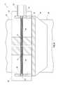
- FIG. 2a prior art rotating control device is representatively illustrated.
- the rotating control device depicted in FIG. 2is used as an example of a type of rotating control device which can be improved using the principles of this disclosure.
- various other types of rotating control devicescan incorporate the principles of this disclosure, as well.
- Rotating control devicesare also known by the terms “rotating control head,” “rotating blowout preventer,” “rotating diverter” and “RCD.”
- a rotating control deviceis used to seal off an annulus 24 formed radially between a body 26 of the rotating control device and a tubular string 28 (such as a drill string) positioned within the body. The annulus 24 is sealed off by the rotating control device, even while the tubular string 28 rotates therein.
- the rotating control deviceincludes one or more annular seals 30 . If multiple seals 30 are used, the rotating control device may include an upper seal housing 54 . To permit the seals 30 to rotate as the tubular string 28 rotates, a bearing assembly 32 is provided in a bearing housing assembly 33 .
- a clamp 34releasably secures the housing assembly 33 (with the bearing assembly 32 and seals 30 therein) to the body 26 , so that the bearing assembly and seals can be removed from the body for maintenance or replacement.
- threaded bolts 36are used to secure ends of the clamp 34 , and so human activity in the area adjacent the rotating control device (e.g., in the moon pool) is needed to unbolt the ends of the clamp whenever the bearing assembly 32 and seals 30 are to be removed from the body 26 . This limits the acceptability of the FIG. 2 rotating control device for use with land rigs, floating rigs, other types of offshore rigs, etc.
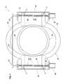
- the improved RCD 12 having the remotely operable clamp device 22is representatively illustrated.
- the lip 38 of the body 26is shown, since the lip is the portion of the body which is engaged by the clamp device 22 in this example.
- FIG. 3An unclamped configuration of the clamp device 22 is depicted in FIG. 3 .
- two clamp sections 40have been displaced outward, thereby permitting removal of the housing assembly 33 , bearing assembly 32 and seals 30 from the body 26 .
- the clamp sections 40are displaced outward (in opposite directions, away from each other) by two fluid motors 42 .
- the motors 42rotate respective threaded members 44 , which are threaded into each of the clamp sections 40 .
- each threaded member 44has two oppositely threaded portions 46 , 48 (e.g., with one portion being right-hand threaded, and the other portion being left-hand threaded).
- a threaded member 44rotates, it will cause the clamp sections 40 to displace in opposite directions (toward or away from each other, depending on the direction of rotation of the threaded member).
- the motors 42 , ends of the clamp sections 40 and ends of the threaded members 44are supported by bracket-type supports 50 .
- the ends of the threaded members 44preferably are rotationally mounted to the supports 50 using, for example, bushings 52 .
- the motors 42are preferably rigidly mounted to the supports 50 , for example, using fasteners (not shown).
- FIGS. 2 & 3Although two each of the clamp sections 40 , motors 42 and threaded members 44 are depicted in FIGS. 2 & 3 , it should be clearly understood that any number (including one) of these components may be used in keeping with the principles of this disclosure.
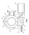
- FIG. 4an enlarged scale side, partially cross-sectional view of the clamp device 22 on the RCD 12 is representatively illustrated.
- the clamp device 22is in a clamped configuration.
- FIG. 5a top, partially cross-sectional view of the clamp device 22 in the closed configuration is representatively illustrated. Although only one lateral side of the clamp device 22 is shown in FIG. 5 , it will be appreciated that the other side is preferably identical to the illustrated side.
- the motors 42are preferably fluid motors, that is, motors which are operated in response to fluid pressure applied thereto.
- the motors 42could be hydraulic or pneumatic motors.
- other types of motorssuch as electric motors could be used, if desired.
- FIG. 6a schematic fluid circuit diagram for operation of the clamp device 22 is representatively illustrated.
- the motors 42are connected via the lines 20 to a pressure source 56 (such as a pump, an accumulator, a pressurized gas container, etc.).
- a pressure source 56such as a pump, an accumulator, a pressurized gas container, etc.
- Pressureis delivered to the motors 42 from the pressure source 56 under control of a control system 58 .
- the control system 58may cause the pressure source 56 to deliver a pressurized fluid flow to one of the lines 20 (with fluid being returned via the other of the lines), in order to cause the motors 42 to rotate the threaded members 44 in one direction.
- the control system 58may cause the pressure source 56 to deliver a pressurized fluid flow to another of the lines 20 (with fluid being returned via the first line), in order to cause the motors 42 to rotate the threaded members 44 in an opposite direction.
- Connectors 60may be provided for connecting the lines 20 to the pressure source 56 , which is preferably positioned at a remote location on the rig 16 .
- the motors 42 and/or threaded members 44are preferably designed so that the threaded members will not rotate if the connectors 60 are disconnected, or if pressurized fluid is not flowed through the lines.
- a pitch of the threads on the threaded members 44could be sufficiently fine, so that any force applied from the clamp sections 40 to the threaded members will not cause the threaded members to rotate. In this manner, the loss of a capability to apply fluid pressure to the motors 42 will not result in any danger that the clamp device 22 will become unclamped, even if the body 26 is internally pressurized.
- the motors 42are preferably connected to the lines 20 in series, so that they operate simultaneously. In this manner, the ends of the clamp sections 40 will be displaced the same distance, at the same time, in equal but opposite directions, by the motors 42 .
- any number of linesmay be used in keeping with the principles of this disclosure. If pressurized gas is used as the fluid, it may not be necessary to flow the gas from the motors 42 back to the pressure source 56 (for example, the gas could be exhausted to atmosphere).
- FIG. 7another configuration of the clamp device 22 is representatively illustrated.
- the configuration of FIG. 7is similar in many respects to the configuration of FIG. 3 .
- the threaded members 44 in the configuration of FIG. 7are constrained to rotate together at the same speed by devices 45 , such as sprockets and a chain, pulleys and a belt, gears, etc. This ensures that the clamp sections 40 are displaced the same distance at the same time on both sides of the body 26 .
- FIG. 7Two of the motors 42 are depicted in FIG. 7 for rotating the threaded members 44 . However, only one motor 42 may be used, if desired.
- the clamp device 22includes a single fluid motor 42 positioned between ends 62 of the clamp sections 40 . Opposite ends 64 of the clamp sections 40 are pivotably mounted to the body 26 at a pivot 66 .
- the motor 42 in the example of FIGS. 8A & Brotates an internally threaded member 44 .
- Externally threaded portions 46 , 48are pivotably mounted to the ends 62 of the clamp sections 40 .
- the threaded portions 46 , 48displace either toward each other, or away from each other, depending on the direction of rotation of the threaded member 44 .
- the clamp device 22is depicted in its clamped arrangement in FIGS. 8A & B. It will be appreciated that, if the threaded member 44 is rotated by the motor 42 to displace the ends 62 of the clamp sections 40 away from each other, the clamp sections will pivot away from each other (on the pivot 66 ), thereby allowing removal or installation of the bearing housing assembly 33 onto the body 26 .
- the motor 42is preferably slidably mounted to the body 26 so that, when the clamp sections 40 are displaced away from each other, the motor can move laterally inward toward the body. When the clamp sections 40 are displaced toward each other, the motor 42 can move laterally outward away from the body 26 .
- the motor 42is preferably a pneumatic motor, and is provided with a gearbox 68 for increasing a torque output of the motor.
- the motor 42is pivotably mounted to one of the clamp section ends 62 .
- the threaded portion 46 of the threaded member 44is received in an internally threaded member 70 pivotably mounted to the other clamp section end 62 .
- a central stabilizer 72is mounted to the support 50 for supporting the threaded member 44 .
- the ends 62 of the clamp sections 40displace either toward or away from each other, with the clamp sections pivoting about the pivot 66 .
- the motor 42 and/or threaded member 44are preferably designed (e.g., with sufficiently fine pitch threads, by providing a brake for the motor, etc.) so that the loss of a capability to apply fluid pressure to the motor will not result in any danger that the clamp device 22 will become unclamped, even if the body 26 is internally pressurized.
- FIG. 10another fluid circuit diagram for the RCD 12 is representatively illustrated.
- This fluid circuit diagramdiffers from the one depicted in FIG. 6 , at least in that the control system 58 is interposed between the pressure source 56 and the motor 42 .
- the control system 58includes valves, etc. to direct pressure from the pressure source 56 to appropriate ones of the lines 20 to operate the motor 42 .
- one or more lines 74may be used to transmit lubrication to the bearing assembly 32 .
- One or more ports 76can be used for connecting the lines 74 to the interior of the housing assembly 33 .
- FIG. 10 fluid circuitOne advantage of the FIG. 10 fluid circuit is that the same pressure source 56 may be used to operate the clamp device 22 , and to deliver lubricant to the bearing assembly 32 .
- the control system 58can direct lubricant to the bearing assembly 32 while the tubular string 28 is rotating within the RCD 12 , and the control system can direct fluid pressure to the motor(s) 42 when needed to operate the clamp device 22 .
- RCD 12in its various configurations is described above as being used in conjunction with the floating rig 16 , it should be clearly understood that the RCD can be used with any types of rigs (e.g., on a drill ship, semi-submersible, jack-up, tension leg, land-based, etc., rigs) in keeping with the principles of this disclosure.
- rigse.g., on a drill ship, semi-submersible, jack-up, tension leg, land-based, etc., rigs
- the pneumatic motor 42 of FIGS. 9A & Bcan be used with the clamp device 22 of FIGS. 3-8B
- the pivoting clamp sections 40 of FIGS. 8A-9Bcan be used with the clamp device of FIGS. 3-7 , etc.
- the clamp device 22can be remotely operated, to thereby permit removal and/or installation of the bearing assembly 32 and seals 30 , without requiring human activity in close proximity to the RCD 12 .
- a rotating control device 12which can include a housing assembly 33 containing a bearing assembly 32 and at least one annular seal 30 which rotates and seals off an annulus 24 between a tubular string 28 and a body 26 of the rotating control device 12 , and a remotely operable clamp device 22 which selectively permits and prevents displacement of the housing assembly 33 relative to the body 26 .
- Pressuremay be selectively supplied to the clamp device 22 from a pressure source 56 , with the pressure source 56 being remotely located relative to the clamp device 22 .
- Lubricantmay also be supplied from the pressure source 56 to the bearing assembly 32 .
- the clamp device 22can include at least one motor 42 which rotates at least one threaded member 44 .
- the motor 42may comprise a fluid motor.
- the threaded member 44may comprise multiple threaded members.
- the motor 42may comprise multiple motors.
- the clamp device 22may selectively permit and prevent separation of the bearing assembly 32 and annular seal 30 from the body 26 .
- the methodcan include rotating at least one threaded member 44 which is rotationally secured relative to a body 26 of the rotating control device 12 ; and displacing at least one clamp section 40 of the clamp device 22 in response to rotation of the threaded member 44 , thereby selectively securing and releasing a bearing assembly 32 and at least one annular seal 30 relative to the body 26 .
- the methodcan also include supplying fluid pressure to at least one fluid motor 42 , thereby causing the fluid motor to rotate the threaded member 44
- the fluid pressurecan be supplied from a location which is remote from the rotating control device 12 .
- the fluid motor 42may comprise a hydraulic or pneumatic motor. Multiple fluid motors 42 can be used for rotating multiple respective threaded members 44 .
- the methodcan include connecting the multiple fluid motors 42 in series, whereby the fluid motors 42 operate simultaneously.
- the above disclosurealso describes a rotating control device 12 which can comprise at least one annular seal 30 which rotates and seals off an annulus 24 between a tubular string 28 and a body 26 of the rotating control device 12 , and a remotely operable clamp device 22 which selectively permits and prevents access to an interior of the body 26 .
- the clamp device 22can include at least one motor 42 which rotates a threaded member 44 .
- a pressure source 56may supply fluid pressure to the motor 42 , and the pressure source 56 may be remotely located from the motor 42 .
- the clamp device 22may selectively prevent and permit separation of a bearing assembly 32 from the body 26 .
- the annular seal 30may rotate relative to the body 26 via the bearing assembly 32 .
- the clamp device 22may selectively prevent and permit separation of the annular seal 30 from the rotating control device 12 .
Landscapes
- Engineering & Computer Science (AREA)
- Life Sciences & Earth Sciences (AREA)
- Geology (AREA)
- Mining & Mineral Resources (AREA)
- Mechanical Engineering (AREA)
- Physics & Mathematics (AREA)
- Environmental & Geological Engineering (AREA)
- Fluid Mechanics (AREA)
- General Life Sciences & Earth Sciences (AREA)
- Geochemistry & Mineralogy (AREA)
- Earth Drilling (AREA)
Abstract
Description
Claims (22)
Priority Applications (1)
| Application Number | Priority Date | Filing Date | Title |
|---|---|---|---|
| US13/300,320US8739863B2 (en) | 2010-11-20 | 2011-11-18 | Remote operation of a rotating control device bearing clamp |
Applications Claiming Priority (4)
| Application Number | Priority Date | Filing Date | Title |
|---|---|---|---|
| PCT/US2010/057539WO2012067627A1 (en) | 2010-11-20 | 2010-11-20 | Remote operation of a rotating control device bearing clamp |
| WOPCT/US2010/057539 | 2010-11-20 | ||
| USPCT/US10/57539 | 2010-11-20 | ||
| US13/300,320US8739863B2 (en) | 2010-11-20 | 2011-11-18 | Remote operation of a rotating control device bearing clamp |
Publications (2)
| Publication Number | Publication Date |
|---|---|
| US20120125636A1 US20120125636A1 (en) | 2012-05-24 |
| US8739863B2true US8739863B2 (en) | 2014-06-03 |
Family
ID=46063248
Family Applications (1)
| Application Number | Title | Priority Date | Filing Date |
|---|---|---|---|
| US13/300,320Active2032-01-01US8739863B2 (en) | 2010-11-20 | 2011-11-18 | Remote operation of a rotating control device bearing clamp |
Country Status (1)
| Country | Link |
|---|---|
| US (1) | US8739863B2 (en) |
Cited By (6)
| Publication number | Priority date | Publication date | Assignee | Title |
|---|---|---|---|---|
| US20140291027A1 (en)* | 2012-04-26 | 2014-10-02 | Jtb Tools & Oilfield Services, Llc | Apparatus and method for the installation or removal of a rotary control device insert or a component thereof |
| US20150226268A1 (en)* | 2012-08-31 | 2015-08-13 | Lenze Drives Gmbh | Geared Motor |
| US9260934B2 (en) | 2010-11-20 | 2016-02-16 | Halliburton Energy Services, Inc. | Remote operation of a rotating control device bearing clamp |
| US10072779B2 (en)* | 2016-07-25 | 2018-09-11 | Glenn Brown | Clamshell coupling |
| US11598172B2 (en) | 2021-01-25 | 2023-03-07 | The Sydco System, Inc. | Rotating head with bypass circuit |
| US12320456B2 (en) | 2019-06-11 | 2025-06-03 | Glenn Brown | Coupling device and a method of using a coupling device |
Families Citing this family (14)
| Publication number | Priority date | Publication date | Assignee | Title |
|---|---|---|---|---|
| US9172217B2 (en) | 2010-11-23 | 2015-10-27 | Woodward, Inc. | Pre-chamber spark plug with tubular electrode and method of manufacturing same |
| US9476347B2 (en) | 2010-11-23 | 2016-10-25 | Woodward, Inc. | Controlled spark ignited flame kernel flow in fuel-fed prechambers |
| US8584648B2 (en) | 2010-11-23 | 2013-11-19 | Woodward, Inc. | Controlled spark ignited flame kernel flow |
| US9494002B2 (en) | 2012-09-06 | 2016-11-15 | Reform Energy Services Corp. | Latching assembly |
| US9828817B2 (en)* | 2012-09-06 | 2017-11-28 | Reform Energy Services Corp. | Latching assembly |
| US9856848B2 (en) | 2013-01-08 | 2018-01-02 | Woodward, Inc. | Quiescent chamber hot gas igniter |
| US8839762B1 (en) | 2013-06-10 | 2014-09-23 | Woodward, Inc. | Multi-chamber igniter |
| US9765682B2 (en) | 2013-06-10 | 2017-09-19 | Woodward, Inc. | Multi-chamber igniter |
| US9653886B2 (en) | 2015-03-20 | 2017-05-16 | Woodward, Inc. | Cap shielded ignition system |
| JP6580701B2 (en) | 2015-03-20 | 2019-09-25 | ウッドワード, インコーポレーテッドWoodward, Inc. | Parallel pre-combustion chamber ignition system |
| US9587446B2 (en)* | 2015-03-26 | 2017-03-07 | Chevron U.S.A. Inc. | Subsea removable flex joint laydown tool |
| JP6613058B2 (en)* | 2015-06-08 | 2019-11-27 | シャープ株式会社 | Self-propelled vacuum cleaner |
| US9890689B2 (en) | 2015-10-29 | 2018-02-13 | Woodward, Inc. | Gaseous fuel combustion |
| US11415041B2 (en) | 2019-09-16 | 2022-08-16 | Woodward, Inc. | Flame triggered and controlled volumetric ignition |
Citations (140)
| Publication number | Priority date | Publication date | Assignee | Title |
|---|---|---|---|---|
| US5651A (en)* | 1848-06-27 | Tjel west and nathan thompson | ||
| US2326941A (en)* | 1940-04-01 | 1943-08-17 | Heitner Joseph | Joint for demountable steel structures |
| US2684166A (en) | 1951-09-10 | 1954-07-20 | Paul A Medearis | Power elevator for oil wells |
| US2897895A (en) | 1956-03-30 | 1959-08-04 | Jersey Prod Res Co | Blowout closure device pressure head |
| US3071188A (en) | 1958-10-29 | 1963-01-01 | Otis Eng Co | Remotely controlled latch for well tools |
| US3142337A (en) | 1960-10-24 | 1964-07-28 | Shell Oil Co | Hydraulic system for underwater wellheads |
| US3163223A (en) | 1961-07-26 | 1964-12-29 | Shell Oil Co | Wellhead connector |
| US3251611A (en) | 1963-04-05 | 1966-05-17 | Shell Oil Co | Wellhead connector |
| US3387851A (en) | 1966-01-12 | 1968-06-11 | Shaffer Tool Works | Tandem stripper sealing apparatus |
| US3472518A (en) | 1966-10-24 | 1969-10-14 | Texaco Inc | Dynamic seal for drill pipe annulus |
| US3561723A (en) | 1968-05-07 | 1971-02-09 | Edward T Cugini | Stripping and blow-out preventer device |
| US3614111A (en) | 1969-10-23 | 1971-10-19 | John Regan | Tool joint stripping stationary blowout preventer with a retrievable packing insert |
| US3621912A (en) | 1969-12-10 | 1971-11-23 | Exxon Production Research Co | Remotely operated rotating wellhead |
| US3695633A (en) | 1970-03-19 | 1972-10-03 | Vetco Offshore Ind Inc | Remotely controlled hydraulically operated connectible and disconnectible flexible joint |
| US3868832A (en) | 1973-03-08 | 1975-03-04 | Morris S Biffle | Rotary drilling head assembly |
| US3967678A (en) | 1975-06-02 | 1976-07-06 | Dresser Industries, Inc. | Stuffing box control system |
| US4033701A (en)* | 1976-04-08 | 1977-07-05 | Halliburton Company | Clamp -- self aligning |
| US4098341A (en) | 1977-02-28 | 1978-07-04 | Hydril Company | Rotating blowout preventer apparatus |
| US4185856A (en) | 1973-04-13 | 1980-01-29 | Mcevoy Oilfield Equipment Company | Pipe joint with remotely operable latch |
| US4258792A (en) | 1979-03-15 | 1981-03-31 | Otis Engineering Corporation | Hydraulic tubing tensioner |
| US4285406A (en) | 1979-08-24 | 1981-08-25 | Smith International, Inc. | Drilling head |
| US4293047A (en) | 1979-08-24 | 1981-10-06 | Smith International, Inc. | Drilling head |
| US4304310A (en) | 1979-08-24 | 1981-12-08 | Smith International, Inc. | Drilling head |
| US4312404A (en) | 1980-05-01 | 1982-01-26 | Lynn International Inc. | Rotating blowout preventer |
| US4416340A (en) | 1981-12-24 | 1983-11-22 | Smith International, Inc. | Rotary drilling head |
| US4448255A (en) | 1982-08-17 | 1984-05-15 | Shaffer Donald U | Rotary blowout preventer |
| US4494609A (en) | 1981-04-29 | 1985-01-22 | Otis Engineering Corporation | Test tree |
| US4526406A (en) | 1981-07-16 | 1985-07-02 | Nelson Norman A | Wellhead connector |
| US4531580A (en) | 1983-07-07 | 1985-07-30 | Cameron Iron Works, Inc. | Rotating blowout preventers |
| US4546828A (en) | 1984-01-10 | 1985-10-15 | Hydril Company | Diverter system and blowout preventer |
| US4601608A (en) | 1985-02-19 | 1986-07-22 | Shell Offshore Inc. | Subsea hydraulic connection method and apparatus |
| US4626135A (en) | 1984-10-22 | 1986-12-02 | Hydril Company | Marine riser well control method and apparatus |
| US4673041A (en) | 1984-10-22 | 1987-06-16 | Otis Engineering Corporation | Connector for well servicing system |
| US4693497A (en) | 1986-06-19 | 1987-09-15 | Cameron Iron Works, Inc. | Collet connector |
| US4754820A (en) | 1986-06-18 | 1988-07-05 | Drilex Systems, Inc. | Drilling head with bayonet coupling |
| US4813495A (en) | 1987-05-05 | 1989-03-21 | Conoco Inc. | Method and apparatus for deepwater drilling |
| US4828024A (en) | 1984-01-10 | 1989-05-09 | Hydril Company | Diverter system and blowout preventer |
| US5022472A (en) | 1989-11-14 | 1991-06-11 | Masx Energy Services Group, Inc. | Hydraulic clamp for rotary drilling head |
| US5085129A (en)* | 1991-03-08 | 1992-02-04 | Golden Technologies Company, Inc. | Joint system |
| US5137084A (en) | 1990-12-20 | 1992-08-11 | The Sydco System, Inc. | Rotating head |
| US5166650A (en)* | 1991-07-25 | 1992-11-24 | Loral Aerospace Corp. | Remote waveguide flange clamp |
| US5178215A (en) | 1991-07-22 | 1993-01-12 | Folsom Metal Products, Inc. | Rotary blowout preventer adaptable for use with both kelly and overhead drive mechanisms |
| US5213158A (en) | 1991-12-20 | 1993-05-25 | Masx Entergy Services Group, Inc. | Dual rotating stripper rubber drilling head |
| US5224557A (en) | 1991-07-22 | 1993-07-06 | Folsom Metal Products, Inc. | Rotary blowout preventer adaptable for use with both kelly and overhead drive mechanisms |
| US5322137A (en) | 1992-10-22 | 1994-06-21 | The Sydco System | Rotating head with elastomeric member rotating assembly |
| US5588491A (en) | 1995-08-10 | 1996-12-31 | Varco Shaffer, Inc. | Rotating blowout preventer and method |
| US5647444A (en) | 1992-09-18 | 1997-07-15 | Williams; John R. | Rotating blowout preventor |
| US5662181A (en) | 1992-09-30 | 1997-09-02 | Williams; John R. | Rotating blowout preventer |
| US5720356A (en) | 1996-02-01 | 1998-02-24 | Gardes; Robert | Method and system for drilling underbalanced radial wells utilizing a dual string technique in a live well |
| WO1999042696A1 (en) | 1998-02-19 | 1999-08-26 | Robert Gardes | Method and system for drilling and completing underbalanced multilateral wells |
| US6016880A (en) | 1997-10-02 | 2000-01-25 | Abb Vetco Gray Inc. | Rotating drilling head with spaced apart seals |
| US6024172A (en) | 1997-09-25 | 2000-02-15 | Lee; Daniel | Blow-out preventer |
| US6109348A (en) | 1996-08-23 | 2000-08-29 | Caraway; Miles F. | Rotating blowout preventer |
| US6129152A (en) | 1998-04-29 | 2000-10-10 | Alpine Oil Services Inc. | Rotating bop and method |
| US6138774A (en) | 1998-03-02 | 2000-10-31 | Weatherford Holding U.S., Inc. | Method and apparatus for drilling a borehole into a subsea abnormal pore pressure environment |
| US6230824B1 (en) | 1998-03-27 | 2001-05-15 | Hydril Company | Rotating subsea diverter |
| US6263982B1 (en) | 1998-03-02 | 2001-07-24 | Weatherford Holding U.S., Inc. | Method and system for return of drilling fluid from a sealed marine riser to a floating drilling rig while drilling |
| US6276450B1 (en) | 1999-05-02 | 2001-08-21 | Varco International, Inc. | Apparatus and method for rapid replacement of upper blowout preventers |
| WO2001083941A1 (en) | 2000-05-03 | 2001-11-08 | Psl Pipeline Process Excavation Norway As | Well pump device |
| WO2001090528A1 (en) | 2000-05-22 | 2001-11-29 | Gardes Robert A | Method for controlled drilling and completing of wells |
| US6325159B1 (en) | 1998-03-27 | 2001-12-04 | Hydril Company | Offshore drilling system |
| WO2002044518A1 (en) | 2000-11-02 | 2002-06-06 | Agr Services As | Tool, method and system for flushing a vertical riser |
| US20020112888A1 (en) | 2000-12-18 | 2002-08-22 | Christian Leuchtenberg | Drilling system and method |
| US6457540B2 (en) | 1996-02-01 | 2002-10-01 | Robert Gardes | Method and system for hydraulic friction controlled drilling and completing geopressured wells utilizing concentric drill strings |
| US6470975B1 (en) | 1999-03-02 | 2002-10-29 | Weatherford/Lamb, Inc. | Internal riser rotating control head |
| WO2003015336A1 (en) | 2001-08-10 | 2003-02-20 | Motorola, Inc., A Corporation Of The State Of Delaware | A method for implementing a modified radio link protocol |
| US20030066650A1 (en) | 1998-07-15 | 2003-04-10 | Baker Hughes Incorporated | Drilling system and method for controlling equivalent circulating density during drilling of wellbores |
| US6547002B1 (en) | 2000-04-17 | 2003-04-15 | Weatherford/Lamb, Inc. | High pressure rotating drilling head assembly with hydraulically removable packer |
| US6554016B2 (en) | 2000-12-12 | 2003-04-29 | Northland Energy Corporation | Rotating blowout preventer with independent cooling circuits and thrust bearing |
| US20030098181A1 (en) | 2001-09-20 | 2003-05-29 | Baker Hughes Incorporated | Active controlled bottomhole pressure system & method |
| US6588502B2 (en) | 2000-12-05 | 2003-07-08 | Baker Hughes, Incorporated | Well pressure activated pack-off head |
| US20040009033A1 (en)* | 2002-07-12 | 2004-01-15 | Rieber Frederick M. | Swing attachment |
| WO2004005667A1 (en) | 2002-07-08 | 2004-01-15 | Shell Internationale Research Maatschappij B.V. | Choke for controlling the flow of drilling mud |
| WO2003025334A8 (en) | 2001-09-14 | 2004-04-22 | Shell Int Research | System for controlling the discharge of drilling fluid |
| US6732804B2 (en) | 2002-05-23 | 2004-05-11 | Weatherford/Lamb, Inc. | Dynamic mudcap drilling and well control system |
| WO2003071091A9 (en) | 2002-02-20 | 2004-06-24 | Shell Int Research | Dynamic annular pressure control apparatus and method |
| WO2004074627A1 (en) | 2003-02-18 | 2004-09-02 | Shell Internationale Research Maatschappij B.V. | Dynamic annular pressure control apparatus and method |
| WO2004085788A3 (en) | 2003-03-13 | 2004-11-25 | Ocean Riser Systems As | Method and arrangement for performing drilling operations |
| WO2005001237A1 (en) | 2003-06-23 | 2005-01-06 | Baker Hughes Incorporated | Downhole activatable annular seal assembly |
| WO2005017308A1 (en) | 2003-08-19 | 2005-02-24 | Shell Internationale Research Maatschappij B.V. | Drilling system and method |
| US6896076B2 (en) | 2001-12-04 | 2005-05-24 | Abb Vetco Gray Inc. | Rotating drilling head gripper |
| US6913092B2 (en) | 1998-03-02 | 2005-07-05 | Weatherford/Lamb, Inc. | Method and system for return of drilling fluid from a sealed marine riser to a floating drilling rig while drilling |
| US6981561B2 (en) | 2001-09-20 | 2006-01-03 | Baker Hughes Incorporated | Downhole cutting mill |
| WO2006029379A1 (en) | 2004-09-09 | 2006-03-16 | Baker Hughes Incorporated | Control systems and methods for active controlled bottomhole pressure systems |
| WO2006031119A1 (en) | 2004-08-19 | 2006-03-23 | Agr Subsea As | Method and system for return of drilling fluid |
| US7040394B2 (en) | 2002-10-31 | 2006-05-09 | Weatherford/Lamb, Inc. | Active/passive seal rotating control head |
| US7055627B2 (en) | 2002-11-22 | 2006-06-06 | Baker Hughes Incorporated | Wellbore fluid circulation system and method |
| US20060124318A1 (en) | 2004-12-14 | 2006-06-15 | Schlumberger Technology Corporation | Control Line Telemetry |
| US20060144622A1 (en) | 2002-10-31 | 2006-07-06 | Weatherford/Lamb, Inc. | Rotating control head radial seal protection and leak detection systems |
| US7096975B2 (en) | 1998-07-15 | 2006-08-29 | Baker Hughes Incorporated | Modular design for downhole ECD-management devices and related methods |
| WO2006099362A1 (en) | 2005-03-11 | 2006-09-21 | Baker Hughes Incorporated | Control systems and methods for real time pressure management (ecdcontrol) |
| WO2006138565A1 (en) | 2005-06-17 | 2006-12-28 | Baker Hughes Incorporated | Active controlled bottomhole pressure system and method with continuous circulation system |
| US7159669B2 (en) | 1999-03-02 | 2007-01-09 | Weatherford/Lamb, Inc. | Internal riser rotating control head |
| US20070012457A1 (en) | 2005-07-13 | 2007-01-18 | Curtis Fredrick D | Underbalanced drilling applications hydraulically operated formation isolation valve |
| WO2007008085A1 (en) | 2005-07-13 | 2007-01-18 | Siem Wis As | System and method for dynamic sealing around a drill stem |
| US7165610B2 (en) | 2003-09-24 | 2007-01-23 | Cameron International Corporation | Removable seal |
| WO2007016000A1 (en) | 2005-07-27 | 2007-02-08 | Baker Hughes Incorporated | Active bottomhole pressure control with liner drilling and compeltion system |
| US7185719B2 (en) | 2002-02-20 | 2007-03-06 | Shell Oil Company | Dynamic annular pressure control apparatus and method |
| US7185718B2 (en) | 1996-02-01 | 2007-03-06 | Robert Gardes | Method and system for hydraulic friction controlled drilling and completing geopressured wells utilizing concentric drill strings |
| WO2007030017A1 (en) | 2005-07-18 | 2007-03-15 | Siem Wis As | Pressure accumulator to establish sufficient power to handle and operate external equipment, and use thereof |
| US20070068704A1 (en) | 1998-07-15 | 2007-03-29 | Baker Hughes Incorporated | Active buttonhole pressure control with liner drilling and completion systems |
| US7237623B2 (en) | 2003-09-19 | 2007-07-03 | Weatherford/Lamb, Inc. | Method for pressurized mud cap and reverse circulation drilling from a floating drilling rig using a sealed marine riser |
| WO2006118920A3 (en) | 2005-04-29 | 2007-07-12 | Shell Oil Co | Systems and methods for managing downhole pressure |
| US7264058B2 (en) | 2001-09-10 | 2007-09-04 | Ocean Riser Systems As | Arrangement and method for regulating bottom hole pressures when drilling deepwater offshore wells |
| US7273102B2 (en) | 2004-05-28 | 2007-09-25 | Schlumberger Technology Corporation | Remotely actuating a casing conveyed tool |
| WO2007126833A1 (en) | 2006-03-29 | 2007-11-08 | Baker Hughes Incorporated | Reverse circulation pressure control method and system |
| US20070278007A1 (en) | 2002-11-22 | 2007-12-06 | Baker Hughes Incorporated | Reverse Circulation Pressure Control Method and System |
| WO2007112292A3 (en) | 2006-03-28 | 2007-12-21 | At Balance Americas Llc | Method for controlling fluid pressure in a borehole using a dynamic annular pressure control system |
| US20080017388A1 (en)* | 2001-06-25 | 2008-01-24 | Emanuel Kulhanek | Well string injection system and method |
| WO2007081711A3 (en) | 2006-01-05 | 2008-02-21 | At Balance Americas Llc | Method for determining formation fluid entry into or drilling fluid loss from a borehole using a dynamic annular pressure control system |
| US7367410B2 (en) | 2002-03-08 | 2008-05-06 | Ocean Riser Systems As | Method and device for liner system |
| US20080105434A1 (en) | 2006-11-07 | 2008-05-08 | Halliburton Energy Services, Inc. | Offshore Universal Riser System |
| WO2008120025A2 (en) | 2007-04-03 | 2008-10-09 | Weatherford/Lamb, Inc. | Rotating control device docking station |
| WO2007124330A3 (en) | 2006-04-20 | 2008-10-16 | At Balance Americas Llc | Pressure safety system for use with a dynamic annular pressure control system |
| US20080251257A1 (en) | 2007-04-11 | 2008-10-16 | Christian Leuchtenberg | Multipart Sliding Joint For Floating Rig |
| WO2008134266A1 (en) | 2007-04-24 | 2008-11-06 | Agr Deepwater Development Systems, Inc. | Subsea well control system and method |
| WO2008133523A1 (en) | 2007-04-27 | 2008-11-06 | Siem Wis As | Seal for a drill string |
| WO2008156376A1 (en) | 2007-06-21 | 2008-12-24 | Siem Wis As | Device and method for maintaining constant pressure on, and flow drill fluid, in a drill string |
| US7472870B2 (en)* | 2004-05-12 | 2009-01-06 | Rilco Manufacturing Company, Inc. | Cryogenic clamp-on pipe anchor |
| WO2009017418A1 (en) | 2007-07-27 | 2009-02-05 | Siem Wis As | Sealing arrangement, and corresponding method |
| US7487837B2 (en) | 2004-11-23 | 2009-02-10 | Weatherford/Lamb, Inc. | Riser rotating control device |
| US20090057021A1 (en) | 2007-08-27 | 2009-03-05 | Williams John R | Bearing assembly inner barrel and well drilling equipment comprising same |
| EP2050924A2 (en) | 2007-10-19 | 2009-04-22 | Weatherford/Lamb Inc. | Oilfield equipment |
| WO2009058706A2 (en) | 2007-11-02 | 2009-05-07 | Agr Subsea, Inc. | Anchored riserless mud return systems |
| US20100006297A1 (en) | 2006-07-14 | 2010-01-14 | Agr Subsea As | Pipe string device for conveying a fluid from a well head to a vessel |
| US7658228B2 (en) | 2005-03-15 | 2010-02-09 | Ocean Riser System | High pressure system |
| WO2008151128A9 (en) | 2007-06-01 | 2010-02-18 | Agr Deepwater Development Systems, Inc. | Dual density mud return system |
| US7665773B2 (en)* | 2006-06-21 | 2010-02-23 | Conocophillips Company | Self-tightening clamp assemblies for protection against full pipe separation |
| US7677329B2 (en) | 2003-11-27 | 2010-03-16 | Agr Subsea As | Method and device for controlling drilling fluid pressure |
| US7699109B2 (en) | 2006-11-06 | 2010-04-20 | Smith International | Rotating control device apparatus and method |
| US7708064B2 (en) | 2007-12-27 | 2010-05-04 | At Balance Americas, Llc | Wellbore pipe centralizer having increased restoring force and self-sealing capability |
| US20100175882A1 (en) | 2009-01-15 | 2010-07-15 | Weatherford/Lamb, Inc. | Subsea Internal Riser Rotating Control Device System and Method |
| EP2216498A2 (en) | 2009-02-06 | 2010-08-11 | Weatherford/Lamb Inc. | Latch position indicator system and method |
| US7779903B2 (en) | 2002-10-31 | 2010-08-24 | Weatherford/Lamb, Inc. | Solid rubber packer for a rotating control device |
| US7806203B2 (en) | 1998-07-15 | 2010-10-05 | Baker Hughes Incorporated | Active controlled bottomhole pressure system and method with continuous circulation system |
| US20110024195A1 (en) | 2009-07-31 | 2011-02-03 | Weatherford/Lamb, Inc. | Drilling with a high pressure rotating control device |
| US20110108282A1 (en) | 2005-10-20 | 2011-05-12 | Transocean Sedco Forex Ventures Limited | Apparatus and Method for Managed Pressure Drilling |
| US20110127040A1 (en) | 2009-12-02 | 2011-06-02 | Gavin Humphreys | Assembly and method for subsea well drilling and intervention |
| GB2478119A (en) | 2010-02-24 | 2011-08-31 | Managed Pressure Operations Llc | A drilling system having a riser closure mounted above a telescopic joint |
| EP2378056A2 (en) | 2010-04-16 | 2011-10-19 | Weatherford Lamb, Inc. | Drilling fluid pressure control system for a floating rig |
- 2011
- 2011-11-18USUS13/300,320patent/US8739863B2/enactiveActive
Patent Citations (186)
| Publication number | Priority date | Publication date | Assignee | Title |
|---|---|---|---|---|
| US5651A (en)* | 1848-06-27 | Tjel west and nathan thompson | ||
| US2326941A (en)* | 1940-04-01 | 1943-08-17 | Heitner Joseph | Joint for demountable steel structures |
| US2684166A (en) | 1951-09-10 | 1954-07-20 | Paul A Medearis | Power elevator for oil wells |
| US2897895A (en) | 1956-03-30 | 1959-08-04 | Jersey Prod Res Co | Blowout closure device pressure head |
| US3071188A (en) | 1958-10-29 | 1963-01-01 | Otis Eng Co | Remotely controlled latch for well tools |
| US3142337A (en) | 1960-10-24 | 1964-07-28 | Shell Oil Co | Hydraulic system for underwater wellheads |
| US3163223A (en) | 1961-07-26 | 1964-12-29 | Shell Oil Co | Wellhead connector |
| US3251611A (en) | 1963-04-05 | 1966-05-17 | Shell Oil Co | Wellhead connector |
| US3387851A (en) | 1966-01-12 | 1968-06-11 | Shaffer Tool Works | Tandem stripper sealing apparatus |
| US3472518A (en) | 1966-10-24 | 1969-10-14 | Texaco Inc | Dynamic seal for drill pipe annulus |
| US3561723A (en) | 1968-05-07 | 1971-02-09 | Edward T Cugini | Stripping and blow-out preventer device |
| US3614111A (en) | 1969-10-23 | 1971-10-19 | John Regan | Tool joint stripping stationary blowout preventer with a retrievable packing insert |
| US3621912A (en) | 1969-12-10 | 1971-11-23 | Exxon Production Research Co | Remotely operated rotating wellhead |
| US3695633A (en) | 1970-03-19 | 1972-10-03 | Vetco Offshore Ind Inc | Remotely controlled hydraulically operated connectible and disconnectible flexible joint |
| US3868832A (en) | 1973-03-08 | 1975-03-04 | Morris S Biffle | Rotary drilling head assembly |
| US4185856A (en) | 1973-04-13 | 1980-01-29 | Mcevoy Oilfield Equipment Company | Pipe joint with remotely operable latch |
| US3967678A (en) | 1975-06-02 | 1976-07-06 | Dresser Industries, Inc. | Stuffing box control system |
| US4033701A (en)* | 1976-04-08 | 1977-07-05 | Halliburton Company | Clamp -- self aligning |
| US4098341A (en) | 1977-02-28 | 1978-07-04 | Hydril Company | Rotating blowout preventer apparatus |
| US4258792A (en) | 1979-03-15 | 1981-03-31 | Otis Engineering Corporation | Hydraulic tubing tensioner |
| US4285406A (en) | 1979-08-24 | 1981-08-25 | Smith International, Inc. | Drilling head |
| US4293047A (en) | 1979-08-24 | 1981-10-06 | Smith International, Inc. | Drilling head |
| US4304310A (en) | 1979-08-24 | 1981-12-08 | Smith International, Inc. | Drilling head |
| US4312404A (en) | 1980-05-01 | 1982-01-26 | Lynn International Inc. | Rotating blowout preventer |
| US4494609A (en) | 1981-04-29 | 1985-01-22 | Otis Engineering Corporation | Test tree |
| US4526406A (en) | 1981-07-16 | 1985-07-02 | Nelson Norman A | Wellhead connector |
| US4416340A (en) | 1981-12-24 | 1983-11-22 | Smith International, Inc. | Rotary drilling head |
| US4448255A (en) | 1982-08-17 | 1984-05-15 | Shaffer Donald U | Rotary blowout preventer |
| US4531580A (en) | 1983-07-07 | 1985-07-30 | Cameron Iron Works, Inc. | Rotating blowout preventers |
| US4546828A (en) | 1984-01-10 | 1985-10-15 | Hydril Company | Diverter system and blowout preventer |
| US4828024A (en) | 1984-01-10 | 1989-05-09 | Hydril Company | Diverter system and blowout preventer |
| US4626135A (en) | 1984-10-22 | 1986-12-02 | Hydril Company | Marine riser well control method and apparatus |
| US4673041A (en) | 1984-10-22 | 1987-06-16 | Otis Engineering Corporation | Connector for well servicing system |
| US4601608A (en) | 1985-02-19 | 1986-07-22 | Shell Offshore Inc. | Subsea hydraulic connection method and apparatus |
| US4754820A (en) | 1986-06-18 | 1988-07-05 | Drilex Systems, Inc. | Drilling head with bayonet coupling |
| US4693497A (en) | 1986-06-19 | 1987-09-15 | Cameron Iron Works, Inc. | Collet connector |
| US4813495A (en) | 1987-05-05 | 1989-03-21 | Conoco Inc. | Method and apparatus for deepwater drilling |
| US5022472A (en) | 1989-11-14 | 1991-06-11 | Masx Energy Services Group, Inc. | Hydraulic clamp for rotary drilling head |
| US5137084A (en) | 1990-12-20 | 1992-08-11 | The Sydco System, Inc. | Rotating head |
| US5085129A (en)* | 1991-03-08 | 1992-02-04 | Golden Technologies Company, Inc. | Joint system |
| US5224557A (en) | 1991-07-22 | 1993-07-06 | Folsom Metal Products, Inc. | Rotary blowout preventer adaptable for use with both kelly and overhead drive mechanisms |
| US5178215A (en) | 1991-07-22 | 1993-01-12 | Folsom Metal Products, Inc. | Rotary blowout preventer adaptable for use with both kelly and overhead drive mechanisms |
| US5277249A (en) | 1991-07-22 | 1994-01-11 | Folsom Metal Products, Inc. | Rotary blowout preventer adaptable for use with both kelly and overhead drive mechanisms |
| US5279365A (en) | 1991-07-22 | 1994-01-18 | Folsom Metal Products, Inc. | Rotary blowout preventer adaptable for use with both kelly and overhead drive mechanisms |
| US5166650A (en)* | 1991-07-25 | 1992-11-24 | Loral Aerospace Corp. | Remote waveguide flange clamp |
| US5213158A (en) | 1991-12-20 | 1993-05-25 | Masx Entergy Services Group, Inc. | Dual rotating stripper rubber drilling head |
| US5647444A (en) | 1992-09-18 | 1997-07-15 | Williams; John R. | Rotating blowout preventor |
| US5662181A (en) | 1992-09-30 | 1997-09-02 | Williams; John R. | Rotating blowout preventer |
| US5409073A (en) | 1992-10-22 | 1995-04-25 | The Sydco System | Rotating head with elastomeric member rotating assembly |
| US5322137A (en) | 1992-10-22 | 1994-06-21 | The Sydco System | Rotating head with elastomeric member rotating assembly |
| US5588491A (en) | 1995-08-10 | 1996-12-31 | Varco Shaffer, Inc. | Rotating blowout preventer and method |
| US6065550A (en) | 1996-02-01 | 2000-05-23 | Gardes; Robert | Method and system for drilling and completing underbalanced multilateral wells utilizing a dual string technique in a live well |
| US5720356A (en) | 1996-02-01 | 1998-02-24 | Gardes; Robert | Method and system for drilling underbalanced radial wells utilizing a dual string technique in a live well |
| US6457540B2 (en) | 1996-02-01 | 2002-10-01 | Robert Gardes | Method and system for hydraulic friction controlled drilling and completing geopressured wells utilizing concentric drill strings |
| US7185718B2 (en) | 1996-02-01 | 2007-03-06 | Robert Gardes | Method and system for hydraulic friction controlled drilling and completing geopressured wells utilizing concentric drill strings |
| US6109348A (en) | 1996-08-23 | 2000-08-29 | Caraway; Miles F. | Rotating blowout preventer |
| US6024172A (en) | 1997-09-25 | 2000-02-15 | Lee; Daniel | Blow-out preventer |
| US6016880A (en) | 1997-10-02 | 2000-01-25 | Abb Vetco Gray Inc. | Rotating drilling head with spaced apart seals |
| WO1999042696A1 (en) | 1998-02-19 | 1999-08-26 | Robert Gardes | Method and system for drilling and completing underbalanced multilateral wells |
| US6913092B2 (en) | 1998-03-02 | 2005-07-05 | Weatherford/Lamb, Inc. | Method and system for return of drilling fluid from a sealed marine riser to a floating drilling rig while drilling |
| US6263982B1 (en) | 1998-03-02 | 2001-07-24 | Weatherford Holding U.S., Inc. | Method and system for return of drilling fluid from a sealed marine riser to a floating drilling rig while drilling |
| US6138774A (en) | 1998-03-02 | 2000-10-31 | Weatherford Holding U.S., Inc. | Method and apparatus for drilling a borehole into a subsea abnormal pore pressure environment |
| US6230824B1 (en) | 1998-03-27 | 2001-05-15 | Hydril Company | Rotating subsea diverter |
| US6325159B1 (en) | 1998-03-27 | 2001-12-04 | Hydril Company | Offshore drilling system |
| US6129152A (en) | 1998-04-29 | 2000-10-10 | Alpine Oil Services Inc. | Rotating bop and method |
| US7096975B2 (en) | 1998-07-15 | 2006-08-29 | Baker Hughes Incorporated | Modular design for downhole ECD-management devices and related methods |
| US7353887B2 (en) | 1998-07-15 | 2008-04-08 | Baker Hughes Incorporated | Control systems and methods for active controlled bottomhole pressure systems |
| US20040206548A1 (en) | 1998-07-15 | 2004-10-21 | Baker Hughes Incorporated | Active controlled bottomhole pressure system & method |
| US20070068704A1 (en) | 1998-07-15 | 2007-03-29 | Baker Hughes Incorporated | Active buttonhole pressure control with liner drilling and completion systems |
| US7721822B2 (en) | 1998-07-15 | 2010-05-25 | Baker Hughes Incorporated | Control systems and methods for real-time downhole pressure management (ECD control) |
| US20030066650A1 (en) | 1998-07-15 | 2003-04-10 | Baker Hughes Incorporated | Drilling system and method for controlling equivalent circulating density during drilling of wellbores |
| US7174975B2 (en) | 1998-07-15 | 2007-02-13 | Baker Hughes Incorporated | Control systems and methods for active controlled bottomhole pressure systems |
| US7806203B2 (en) | 1998-07-15 | 2010-10-05 | Baker Hughes Incorporated | Active controlled bottomhole pressure system and method with continuous circulation system |
| US7270185B2 (en) | 1998-07-15 | 2007-09-18 | Baker Hughes Incorporated | Drilling system and method for controlling equivalent circulating density during drilling of wellbores |
| US20060065402A9 (en) | 1998-07-15 | 2006-03-30 | Baker Hughes Incorporated | Drilling system and method for controlling equivalent circulating density during drilling of wellbores |
| US7258171B2 (en) | 1999-03-02 | 2007-08-21 | Weatherford/Lamb, Inc. | Internal riser rotating control head |
| US6470975B1 (en) | 1999-03-02 | 2002-10-29 | Weatherford/Lamb, Inc. | Internal riser rotating control head |
| US7159669B2 (en) | 1999-03-02 | 2007-01-09 | Weatherford/Lamb, Inc. | Internal riser rotating control head |
| US6276450B1 (en) | 1999-05-02 | 2001-08-21 | Varco International, Inc. | Apparatus and method for rapid replacement of upper blowout preventers |
| US6547002B1 (en) | 2000-04-17 | 2003-04-15 | Weatherford/Lamb, Inc. | High pressure rotating drilling head assembly with hydraulically removable packer |
| US6702012B2 (en) | 2000-04-17 | 2004-03-09 | Weatherford/Lamb, Inc. | High pressure rotating drilling head assembly with hydraulically removable packer |
| US7080685B2 (en) | 2000-04-17 | 2006-07-25 | Weatherford/Lamb, Inc. | High pressure rotating drilling head assembly with hydraulically removable packer |
| WO2001083941A1 (en) | 2000-05-03 | 2001-11-08 | Psl Pipeline Process Excavation Norway As | Well pump device |
| WO2001090528A1 (en) | 2000-05-22 | 2001-11-29 | Gardes Robert A | Method for controlled drilling and completing of wells |
| WO2002044518A1 (en) | 2000-11-02 | 2002-06-06 | Agr Services As | Tool, method and system for flushing a vertical riser |
| US6588502B2 (en) | 2000-12-05 | 2003-07-08 | Baker Hughes, Incorporated | Well pressure activated pack-off head |
| US6953085B2 (en) | 2000-12-05 | 2005-10-11 | Baker Hughes Incorporated | Well pressure activated pack-off head |
| US7004444B2 (en) | 2000-12-12 | 2006-02-28 | Precision Drilling Technology Services Group, Inc. | Rotating blowout preventer with independent cooling circuits and thrust bearing |
| US7007913B2 (en) | 2000-12-12 | 2006-03-07 | Precision Drilling Technology Services Group, Inc. | Rotating blowout preventer with independent cooling circuits and thrust bearing |
| US6749172B2 (en) | 2000-12-12 | 2004-06-15 | Precision Drilling Technology Services Group, Inc. | Rotating blowout preventer with independent cooling circuits and thrust bearing |
| US6554016B2 (en) | 2000-12-12 | 2003-04-29 | Northland Energy Corporation | Rotating blowout preventer with independent cooling circuits and thrust bearing |
| US7367411B2 (en) | 2000-12-18 | 2008-05-06 | Secure Drilling International, L.P. | Drilling system and method |
| US7278496B2 (en) | 2000-12-18 | 2007-10-09 | Christian Leuchtenberg | Drilling system and method |
| US7650950B2 (en) | 2000-12-18 | 2010-01-26 | Secure Drilling International, L.P. | Drilling system and method |
| EP1356186B1 (en) | 2000-12-18 | 2005-06-29 | Impact Solutions Group Limited | Closed loop fluid-handing system for well drilling |
| US7044237B2 (en) | 2000-12-18 | 2006-05-16 | Impact Solutions Group Limited | Drilling system and method |
| US20020112888A1 (en) | 2000-12-18 | 2002-08-22 | Christian Leuchtenberg | Drilling system and method |
| US20080017388A1 (en)* | 2001-06-25 | 2008-01-24 | Emanuel Kulhanek | Well string injection system and method |
| WO2003015336A1 (en) | 2001-08-10 | 2003-02-20 | Motorola, Inc., A Corporation Of The State Of Delaware | A method for implementing a modified radio link protocol |
| US7497266B2 (en) | 2001-09-10 | 2009-03-03 | Ocean Riser Systems As | Arrangement and method for controlling and regulating bottom hole pressure when drilling deepwater offshore wells |
| US7264058B2 (en) | 2001-09-10 | 2007-09-04 | Ocean Riser Systems As | Arrangement and method for regulating bottom hole pressures when drilling deepwater offshore wells |
| WO2003025334A8 (en) | 2001-09-14 | 2004-04-22 | Shell Int Research | System for controlling the discharge of drilling fluid |
| EP1432887B1 (en) | 2001-09-14 | 2006-03-29 | Shell Internationale Researchmaatschappij B.V. | System for controlling the discharge of drilling fluid |
| US7134489B2 (en) | 2001-09-14 | 2006-11-14 | Shell Oil Company | System for controlling the discharge of drilling fluid |
| US6981561B2 (en) | 2001-09-20 | 2006-01-03 | Baker Hughes Incorporated | Downhole cutting mill |
| US20030098181A1 (en) | 2001-09-20 | 2003-05-29 | Baker Hughes Incorporated | Active controlled bottomhole pressure system & method |
| US6896076B2 (en) | 2001-12-04 | 2005-05-24 | Abb Vetco Gray Inc. | Rotating drilling head gripper |
| EP1488073B1 (en) | 2002-02-20 | 2006-08-09 | Shell Internationale Research Maatschappij B.V. | Dynamic annular pressure control apparatus and method |
| WO2003071091A9 (en) | 2002-02-20 | 2004-06-24 | Shell Int Research | Dynamic annular pressure control apparatus and method |
| US6904981B2 (en) | 2002-02-20 | 2005-06-14 | Shell Oil Company | Dynamic annular pressure control apparatus and method |
| US7185719B2 (en) | 2002-02-20 | 2007-03-06 | Shell Oil Company | Dynamic annular pressure control apparatus and method |
| US7367410B2 (en) | 2002-03-08 | 2008-05-06 | Ocean Riser Systems As | Method and device for liner system |
| US6732804B2 (en) | 2002-05-23 | 2004-05-11 | Weatherford/Lamb, Inc. | Dynamic mudcap drilling and well control system |
| WO2004005667A1 (en) | 2002-07-08 | 2004-01-15 | Shell Internationale Research Maatschappij B.V. | Choke for controlling the flow of drilling mud |
| US20060086538A1 (en) | 2002-07-08 | 2006-04-27 | Shell Oil Company | Choke for controlling the flow of drilling mud |
| US20070240875A1 (en) | 2002-07-08 | 2007-10-18 | Van Riet Egbert J | Choke for controlling the flow of drilling mud |
| US20040009033A1 (en)* | 2002-07-12 | 2004-01-15 | Rieber Frederick M. | Swing attachment |
| US7836946B2 (en) | 2002-10-31 | 2010-11-23 | Weatherford/Lamb, Inc. | Rotating control head radial seal protection and leak detection systems |
| US7040394B2 (en) | 2002-10-31 | 2006-05-09 | Weatherford/Lamb, Inc. | Active/passive seal rotating control head |
| US20060144622A1 (en) | 2002-10-31 | 2006-07-06 | Weatherford/Lamb, Inc. | Rotating control head radial seal protection and leak detection systems |
| US7926560B2 (en) | 2002-10-31 | 2011-04-19 | Weatherford/Lamb, Inc. | Solid rubber packer for a rotating control device |
| US7779903B2 (en) | 2002-10-31 | 2010-08-24 | Weatherford/Lamb, Inc. | Solid rubber packer for a rotating control device |
| US7055627B2 (en) | 2002-11-22 | 2006-06-06 | Baker Hughes Incorporated | Wellbore fluid circulation system and method |
| US20070278007A1 (en) | 2002-11-22 | 2007-12-06 | Baker Hughes Incorporated | Reverse Circulation Pressure Control Method and System |
| EP1595057B1 (en) | 2003-02-18 | 2006-07-19 | Shell Internationale Research Maatschappij B.V. | Dynamic annular pressure control apparatus and method |
| WO2004074627A1 (en) | 2003-02-18 | 2004-09-02 | Shell Internationale Research Maatschappij B.V. | Dynamic annular pressure control apparatus and method |
| US20060169491A1 (en) | 2003-03-13 | 2006-08-03 | Ocean Riser Systems As | Method and arrangement for performing drilling operations |
| WO2004085788A3 (en) | 2003-03-13 | 2004-11-25 | Ocean Riser Systems As | Method and arrangement for performing drilling operations |
| US7513310B2 (en) | 2003-03-13 | 2009-04-07 | Ocean Riser Systems As | Method and arrangement for performing drilling operations |
| WO2005001237A1 (en) | 2003-06-23 | 2005-01-06 | Baker Hughes Incorporated | Downhole activatable annular seal assembly |
| US7350597B2 (en) | 2003-08-19 | 2008-04-01 | At-Balance Americas Llc | Drilling system and method |
| WO2005017308A1 (en) | 2003-08-19 | 2005-02-24 | Shell Internationale Research Maatschappij B.V. | Drilling system and method |
| US7395878B2 (en) | 2003-08-19 | 2008-07-08 | At-Balance Americas, Llc | Drilling system and method |
| EP1664478B1 (en) | 2003-08-19 | 2006-12-27 | Shell Internationale Researchmaatschappij B.V. | Drilling system and method |
| US7237623B2 (en) | 2003-09-19 | 2007-07-03 | Weatherford/Lamb, Inc. | Method for pressurized mud cap and reverse circulation drilling from a floating drilling rig using a sealed marine riser |
| US7165610B2 (en) | 2003-09-24 | 2007-01-23 | Cameron International Corporation | Removable seal |
| US7677329B2 (en) | 2003-11-27 | 2010-03-16 | Agr Subsea As | Method and device for controlling drilling fluid pressure |
| US7472870B2 (en)* | 2004-05-12 | 2009-01-06 | Rilco Manufacturing Company, Inc. | Cryogenic clamp-on pipe anchor |
| US7273102B2 (en) | 2004-05-28 | 2007-09-25 | Schlumberger Technology Corporation | Remotely actuating a casing conveyed tool |
| WO2006031119A1 (en) | 2004-08-19 | 2006-03-23 | Agr Subsea As | Method and system for return of drilling fluid |
| WO2006029379A1 (en) | 2004-09-09 | 2006-03-16 | Baker Hughes Incorporated | Control systems and methods for active controlled bottomhole pressure systems |
| US7487837B2 (en) | 2004-11-23 | 2009-02-10 | Weatherford/Lamb, Inc. | Riser rotating control device |
| US7926593B2 (en) | 2004-11-23 | 2011-04-19 | Weatherford/Lamb, Inc. | Rotating control device docking station |
| US20110168392A1 (en) | 2004-11-23 | 2011-07-14 | Weatherford/Lamb, Inc. | Remote Operation of an Oilfield Device |
| US20060124318A1 (en) | 2004-12-14 | 2006-06-15 | Schlumberger Technology Corporation | Control Line Telemetry |
| WO2006099362A1 (en) | 2005-03-11 | 2006-09-21 | Baker Hughes Incorporated | Control systems and methods for real time pressure management (ecdcontrol) |
| US7658228B2 (en) | 2005-03-15 | 2010-02-09 | Ocean Riser System | High pressure system |
| WO2006118920A3 (en) | 2005-04-29 | 2007-07-12 | Shell Oil Co | Systems and methods for managing downhole pressure |
| WO2006138565A1 (en) | 2005-06-17 | 2006-12-28 | Baker Hughes Incorporated | Active controlled bottomhole pressure system and method with continuous circulation system |
| WO2007008085A1 (en) | 2005-07-13 | 2007-01-18 | Siem Wis As | System and method for dynamic sealing around a drill stem |
| US20070012457A1 (en) | 2005-07-13 | 2007-01-18 | Curtis Fredrick D | Underbalanced drilling applications hydraulically operated formation isolation valve |
| US20090211239A1 (en) | 2005-07-18 | 2009-08-27 | Siem Wis As | Pressure accumulator to establish sufficient power to handle and operate external equipment and use thereof |
| WO2007030017A1 (en) | 2005-07-18 | 2007-03-15 | Siem Wis As | Pressure accumulator to establish sufficient power to handle and operate external equipment, and use thereof |
| WO2007016000A1 (en) | 2005-07-27 | 2007-02-08 | Baker Hughes Incorporated | Active bottomhole pressure control with liner drilling and compeltion system |
| US20110108282A1 (en) | 2005-10-20 | 2011-05-12 | Transocean Sedco Forex Ventures Limited | Apparatus and Method for Managed Pressure Drilling |
| WO2007081711A3 (en) | 2006-01-05 | 2008-02-21 | At Balance Americas Llc | Method for determining formation fluid entry into or drilling fluid loss from a borehole using a dynamic annular pressure control system |
| US7562723B2 (en) | 2006-01-05 | 2009-07-21 | At Balance Americas, Llc | Method for determining formation fluid entry into or drilling fluid loss from a borehole using a dynamic annular pressure control system |
| WO2007112292A3 (en) | 2006-03-28 | 2007-12-21 | At Balance Americas Llc | Method for controlling fluid pressure in a borehole using a dynamic annular pressure control system |
| WO2007126833A1 (en) | 2006-03-29 | 2007-11-08 | Baker Hughes Incorporated | Reverse circulation pressure control method and system |
| WO2007124330A3 (en) | 2006-04-20 | 2008-10-16 | At Balance Americas Llc | Pressure safety system for use with a dynamic annular pressure control system |
| US7665773B2 (en)* | 2006-06-21 | 2010-02-23 | Conocophillips Company | Self-tightening clamp assemblies for protection against full pipe separation |
| US20100006297A1 (en) | 2006-07-14 | 2010-01-14 | Agr Subsea As | Pipe string device for conveying a fluid from a well head to a vessel |
| US7699109B2 (en) | 2006-11-06 | 2010-04-20 | Smith International | Rotating control device apparatus and method |
| US20100018715A1 (en) | 2006-11-07 | 2010-01-28 | Halliburton Energy Services, Inc. | Offshore universal riser system |
| US20080105434A1 (en) | 2006-11-07 | 2008-05-08 | Halliburton Energy Services, Inc. | Offshore Universal Riser System |
| US8033335B2 (en) | 2006-11-07 | 2011-10-11 | Halliburton Energy Services, Inc. | Offshore universal riser system |
| WO2008120025A2 (en) | 2007-04-03 | 2008-10-09 | Weatherford/Lamb, Inc. | Rotating control device docking station |
| US20080251257A1 (en) | 2007-04-11 | 2008-10-16 | Christian Leuchtenberg | Multipart Sliding Joint For Floating Rig |
| WO2008134266A1 (en) | 2007-04-24 | 2008-11-06 | Agr Deepwater Development Systems, Inc. | Subsea well control system and method |
| EP2150681A1 (en) | 2007-04-27 | 2010-02-10 | Siem Wis As | Seal for a drill string |
| WO2008133523A1 (en) | 2007-04-27 | 2008-11-06 | Siem Wis As | Seal for a drill string |
| WO2008151128A9 (en) | 2007-06-01 | 2010-02-18 | Agr Deepwater Development Systems, Inc. | Dual density mud return system |
| WO2008156376A1 (en) | 2007-06-21 | 2008-12-24 | Siem Wis As | Device and method for maintaining constant pressure on, and flow drill fluid, in a drill string |
| WO2009017418A1 (en) | 2007-07-27 | 2009-02-05 | Siem Wis As | Sealing arrangement, and corresponding method |
| US20090057021A1 (en) | 2007-08-27 | 2009-03-05 | Williams John R | Bearing assembly inner barrel and well drilling equipment comprising same |
| US20090101351A1 (en) | 2007-10-19 | 2009-04-23 | Weatherford/Lamb, Inc. | Universal marine diverter converter |
| EP2050924A2 (en) | 2007-10-19 | 2009-04-22 | Weatherford/Lamb Inc. | Oilfield equipment |
| WO2009058706A2 (en) | 2007-11-02 | 2009-05-07 | Agr Subsea, Inc. | Anchored riserless mud return systems |
| US7708064B2 (en) | 2007-12-27 | 2010-05-04 | At Balance Americas, Llc | Wellbore pipe centralizer having increased restoring force and self-sealing capability |
| EP2208855A2 (en) | 2009-01-15 | 2010-07-21 | Weatherford Lamb, Inc. | Subsea rotating control device system internal to a riser and method |
| US20100175882A1 (en) | 2009-01-15 | 2010-07-15 | Weatherford/Lamb, Inc. | Subsea Internal Riser Rotating Control Device System and Method |
| EP2216498A2 (en) | 2009-02-06 | 2010-08-11 | Weatherford/Lamb Inc. | Latch position indicator system and method |
| US20110024195A1 (en) | 2009-07-31 | 2011-02-03 | Weatherford/Lamb, Inc. | Drilling with a high pressure rotating control device |
| US20110127040A1 (en) | 2009-12-02 | 2011-06-02 | Gavin Humphreys | Assembly and method for subsea well drilling and intervention |
| GB2478119A (en) | 2010-02-24 | 2011-08-31 | Managed Pressure Operations Llc | A drilling system having a riser closure mounted above a telescopic joint |
| EP2378056A2 (en) | 2010-04-16 | 2011-10-19 | Weatherford Lamb, Inc. | Drilling fluid pressure control system for a floating rig |
Non-Patent Citations (25)
| Title |
|---|
| Cameron; "Deepwater Collet Connector", web page, dated 2006, 1 page. |
| Diamond Rotating Heads, Inc.; Diamond Model 8000/9000, Technical data sheet, received Dec. 3, 2010, 2 pages. |
| Diamond Rotating Heads, Inc.; Product information, company brochure, received Dec. 3, 2010, 4 pages. |
| Don Hannegan; "Offshore drilling hazard mitigation: Controlled pressure drilling redefines what is drillable", Drilling Contractor magazine, dated Jan./Feb. 2009, 4 pages. |
| Halliburton Energy Services, Inc.; "RCD 1000 Rotating Control Device", H07903, dated Aug. 2010, 2 pages. |
| Halliburton Energy Services, Inc.; "RCD 5000 Rotating Control Device", H05284, dated Feb. 2010, 8 pages. |
| International Preliminary Report on Patentability issued Oct. 4, 2012 for US PCT Patent Application No. PCT/US2011/029116, 6 pages. |
| International Search Report with Written Opinion issued Aug. 19, 2011 for International Patent Application No. PCT/US/10/057539, 12 pages. |
| International Search Report with Written Opinion issued Aug. 19, 2011 for International Patent Application No. PCT/US/10/057540, 11 pages. |
| International Search Report with Written Opinion issued Sep. 28, 2011 for International Patent Application No. PCT/US11/029116, 9 pages. |
| International Search Report with Written Opinion issued Sep. 29, 2011 for International Patent Application No. PCT/US11/028384, 11 pages. |
| Oceaneering; "Remotely Operated Connectors", Grayloc Products webpage, received Feb. 18, 2010, 2 pages. |
| Smith Services; "Hold 2500 Rotating Control Device", brochure SS-04-0055.10M, dated 2004, 4 pages. |
| Smith Services; "Marine Riser RCD", company presentation, dated Jul. 2009, 18 pages. |
| Vector Group; "Optima Subsea Connector", company web page, dated 2010, 2 pages. |
| Vetcogray; "H-4 Subsea Connectors", GE Oil & Gas article, dated Jan. 9, 2008, 7 pages. |
| Weatherford; "Model 7000", Technical data sheet, dated Nov. 2006, 2 pages. |
| Weatherford; "Model 7100" Technical data sheet, dated Nov. 2006, 2 pages. |
| Weatherford; "Model 7800 Rotating Control Device" Technical data sheet, dated Nov. 2006, 2 pages. |
| Weatherford; "Model 7875 Rotating Control Device", 4594.01, dated 2010, 4 pages. |
| Weatherford; "Model 8000" Technical data sheet, dated Nov. 2006, 2 pages. |
| Weatherford; "Model 9000" Technical data sheet, dated Nov. 2006, 2 pages. |
| Weatherford; "Model IP 1000" Technical data sheet, dated Nov. 2006, 2 pages. |
| Weatherford; "Weatherford Model 7800 Rotating Control Device", 4593.00, dated 2007, 5 pages. |
| Weatherford; "Williams Model IP 1000", brochure # 325.02, dated 2002, 2 pages. |
Cited By (8)
| Publication number | Priority date | Publication date | Assignee | Title |
|---|---|---|---|---|
| US9260934B2 (en) | 2010-11-20 | 2016-02-16 | Halliburton Energy Services, Inc. | Remote operation of a rotating control device bearing clamp |
| US20140291027A1 (en)* | 2012-04-26 | 2014-10-02 | Jtb Tools & Oilfield Services, Llc | Apparatus and method for the installation or removal of a rotary control device insert or a component thereof |
| US8881801B2 (en)* | 2012-04-26 | 2014-11-11 | Jtb Tools & Oilfield Services, Llc | Apparatus and method for the installation or removal of a rotary control device insert or a component thereof |
| US20150226268A1 (en)* | 2012-08-31 | 2015-08-13 | Lenze Drives Gmbh | Geared Motor |
| US10060481B2 (en)* | 2012-08-31 | 2018-08-28 | Lenze Drives Gmbh | Geared motor |
| US10072779B2 (en)* | 2016-07-25 | 2018-09-11 | Glenn Brown | Clamshell coupling |
| US12320456B2 (en) | 2019-06-11 | 2025-06-03 | Glenn Brown | Coupling device and a method of using a coupling device |
| US11598172B2 (en) | 2021-01-25 | 2023-03-07 | The Sydco System, Inc. | Rotating head with bypass circuit |
Also Published As
| Publication number | Publication date |
|---|---|
| US20120125636A1 (en) | 2012-05-24 |
Similar Documents
| Publication | Publication Date | Title |
|---|---|---|
| US8739863B2 (en) | Remote operation of a rotating control device bearing clamp | |
| US10145199B2 (en) | Remote operation of a rotating control device bearing clamp and safety latch | |
| US6554072B1 (en) | Co-linear tensioner and methods for assembling production and drilling risers using same | |
| US6530430B2 (en) | Tensioner/slip-joint assembly | |
| AU2010346598B2 (en) | Pressure control device with remote orientation relative to a rig | |
| US7219739B2 (en) | Heave compensation system for hydraulic workover | |
| CN107107998A (en) | Offshore drilling system, vessel and method | |
| US20060254776A1 (en) | Co-linear tensioner and methods of installing and removing same | |
| US9260934B2 (en) | Remote operation of a rotating control device bearing clamp | |
| US7314087B2 (en) | Heave compensation system for hydraulic workover | |
| AU2010363985B2 (en) | Remote operation of a rotating control device bearing clamp | |
| AU2011329491B2 (en) | Remote operation of a rotating control device bearing clamp and safety latch | |
| EP3980326B1 (en) | Offshore drilling system, vessel and method | |
| AU2014202256B2 (en) | Pressure control device with remote orientation relative to a rig |
Legal Events
| Date | Code | Title | Description |
|---|---|---|---|
| AS | Assignment | Owner name:HALLIBURTON ENERGY SERVICES, INC., TEXAS Free format text:ASSIGNMENT OF ASSIGNORS INTEREST;ASSIGNORS:LINDE, LEONARD CHARLES;CURTIS, FREDRICK D.;LEWIS, DERRICK W.;AND OTHERS;SIGNING DATES FROM 20110318 TO 20110322;REEL/FRAME:027264/0592 Owner name:DIAMOND ROTATING HEADS, INC., TEXAS Free format text:ASSIGNMENT OF ASSIGNORS INTEREST;ASSIGNOR:CENTRIFLO PUMP & MACHINE COMPANY;REEL/FRAME:027264/0620 Effective date:20100310 Owner name:DIAMOND ROTATING HEADS, INC., TEXAS Free format text:ASSIGNMENT OF ASSIGNORS INTEREST;ASSIGNOR:LOOPER, PAT;REEL/FRAME:027261/0626 Effective date:20100310 Owner name:HALLIBURTON ENERGY SERVICES, INC., TEXAS Free format text:MERGER;ASSIGNOR:DIAMOND ROTATING HEADS, INC.;REEL/FRAME:027259/0843 Effective date:20100622 | |
| FEPP | Fee payment procedure | Free format text:PAYOR NUMBER ASSIGNED (ORIGINAL EVENT CODE: ASPN); ENTITY STATUS OF PATENT OWNER: LARGE ENTITY | |
| STCF | Information on status: patent grant | Free format text:PATENTED CASE | |
| FPAY | Fee payment | Year of fee payment:4 | |
| MAFP | Maintenance fee payment | Free format text:PAYMENT OF MAINTENANCE FEE, 8TH YEAR, LARGE ENTITY (ORIGINAL EVENT CODE: M1552); ENTITY STATUS OF PATENT OWNER: LARGE ENTITY Year of fee payment:8 |