US8739854B2 - Pre-assembled and pre-tensioned shade with indexing gear tensioner - Google Patents
Pre-assembled and pre-tensioned shade with indexing gear tensionerDownload PDFInfo
- Publication number
- US8739854B2 US8739854B2US13/539,736US201213539736AUS8739854B2US 8739854 B2US8739854 B2US 8739854B2US 201213539736 AUS201213539736 AUS 201213539736AUS 8739854 B2US8739854 B2US 8739854B2
- Authority
- US
- United States
- Prior art keywords
- gear
- housing
- spindle
- assembly
- counterbalance
- Prior art date
- Legal status (The legal status is an assumption and is not a legal conclusion. Google has not performed a legal analysis and makes no representation as to the accuracy of the status listed.)
- Expired - Fee Related
Links
- 230000008878couplingEffects0.000claimsdescription2
- 238000010168coupling processMethods0.000claimsdescription2
- 238000005859coupling reactionMethods0.000claimsdescription2
- 230000000712assemblyEffects0.000description7
- 238000000429assemblyMethods0.000description7
- 238000010276constructionMethods0.000description4
- 238000009434installationMethods0.000description4
- 241000269799Perca fluviatilisSpecies0.000description2
- 230000013011matingEffects0.000description2
- 238000000034methodMethods0.000description2
- 230000005540biological transmissionEffects0.000description1
- 230000003071parasitic effectEffects0.000description1
- 238000005381potential energyMethods0.000description1
Images


Classifications
- E—FIXED CONSTRUCTIONS
- E06—DOORS, WINDOWS, SHUTTERS, OR ROLLER BLINDS IN GENERAL; LADDERS
- E06B—FIXED OR MOVABLE CLOSURES FOR OPENINGS IN BUILDINGS, VEHICLES, FENCES OR LIKE ENCLOSURES IN GENERAL, e.g. DOORS, WINDOWS, BLINDS, GATES
- E06B9/00—Screening or protective devices for wall or similar openings, with or without operating or securing mechanisms; Closures of similar construction
- E06B9/56—Operating, guiding or securing devices or arrangements for roll-type closures; Spring drums; Tape drums; Counterweighting arrangements therefor
- E06B9/60—Spring drums operated only by closure members
- E—FIXED CONSTRUCTIONS
- E06—DOORS, WINDOWS, SHUTTERS, OR ROLLER BLINDS IN GENERAL; LADDERS
- E06B—FIXED OR MOVABLE CLOSURES FOR OPENINGS IN BUILDINGS, VEHICLES, FENCES OR LIKE ENCLOSURES IN GENERAL, e.g. DOORS, WINDOWS, BLINDS, GATES
- E06B9/00—Screening or protective devices for wall or similar openings, with or without operating or securing mechanisms; Closures of similar construction
- E06B9/56—Operating, guiding or securing devices or arrangements for roll-type closures; Spring drums; Tape drums; Counterweighting arrangements therefor
- E06B9/80—Safety measures against dropping or unauthorised opening; Braking or immobilising devices; Devices for limiting unrolling
- E06B2009/807—Brakes preventing fast screen movement
Definitions
- the present inventionis generally directed to shade assemblies.
- the present inventionis directed to a tensioning device used with shade assemblies.
- the present inventionis directed to a tensioning device wherein the tension is set in a factory or at installation of the shade assembly.
- Shade or blind assemblies used with windows or similar openingsare well known.
- the assembliesprovide for privacy when desired and block sunlight or allow sunlight to enter a room.
- Many types of shadesare configured with vertical or horizontal slats that are raised and lowered, or moved sideways, by a chord wherein the angular position adjustment of the slats can also be provided. Both adjustments can be automated or manually implemented.
- the shade assembliescan be programmed to open and close at particular times of day or evening so as to let in sunlight when desired or block sunlight when heat in the room becomes uncomfortable.
- the internal mechanism for raising and lowering of the shademay incorporate a counterbalance assembly.
- the counterbalance assemblywhich usually includes a spring, is utilized to compensate for the weight of the shade and reduces strain on the motor, if provided.
- the counterbalance springmay be pre-tensioned so as to prevent excessive current draw by the motor which drains the battery more quickly and causes the motor to wear prematurely.
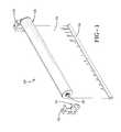
- FIG. 1is a perspective view of a roller shade assembly made in accordance with the concepts of the present invention
- FIG. 2is a perspective view showing a shade drive assembly maintained within the roller shade assembly according to the concepts of the present invention
- FIG. 3is an end view of the shade drive assembly showing internal components of a gear tensioner made in accordance with the concepts of the present invention
- FIG. 4is an exploded perspective view of the gear tensioner according to the concepts of the present invention.
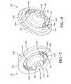
- FIG. 5is a right side perspective view of the gear tensioner
- FIG. 6is an exploded cross-sectional view of the gear tensioner
- FIG. 7is a left side perspective view of selected components of the gear tensioner according to the concepts of the present invention.
- FIG. 8is a right side perspective view of selected components of the gear tensioner according to the concepts of the present invention.
- FIG. 9is a left side perspective view of other selected components of the gear tensioner according to the concepts of the present invention.
- FIG. 10is a perspective view showing an alternative shade drive assembly maintained within the roller shade assembly according to the concepts of the present invention.
- FIG. 11is a left side perspective view of selected components of the alternative gear tensioner according to the concepts of the present invention.
- FIG. 12is a right side perspective view of selected components of the alternative gear tensioner according to the concepts of the present invention.
- a roller shade assemblyaccording to the concepts of the present invention is designated generally by the numeral 20 .
- the assembly 20includes a covering 22 which could be a shade or a blind or any other covering of a window or similar opening. Skilled artisans will appreciate that the roller shade assembly is typically installed on the interior side of a window or opening, but in some instances the assembly may be installed on the exterior side. Attached to the covering 22 is a bottom bar 24 which is disposed at a distal end of the covering wherein the other end of the covering is attached to a storage roll 26 .
- the storage rollis typically of a tubular construction so as to hold internal components as will be discussed.
- the covering 22wraps around the storage roll 26 when in an open or upward position and unwraps or unreels from the storage roll when moved to a closed or lowered position.
- Extending axially from the storage roll 26are a pair of opposed support shafts 28 .
- a bearing housing 56is radially disposed between the support shaft and the interior surface of the storage roll 26 .
- a support bracket 32is mounted to the structure surrounding the opening or window with fasteners or the like. Each bracket 32 provides a bracket slot 34 which rotatably receives the support shafts 28 . As such, the storage roll 26 is allowed to freely rotate between the bracket slots 34 .
- the storage roll 26is of a tubular construction.
- the roll 26has an exterior surface 36 and an interior surface 38 which forms a hollow interior 40 .
- the exterior surface 36provides for an outer channel 42 which receives a shade clip 44 that is attached to a surface of the shade covering 22 so as to provide for a secure attachment between the storage roll 26 and the covering 22 .
- the interior surface 38includes a plurality of inner tabs 46 which extend radially inwardly. Each tab 46 provides semi-rigid tab ends 48 which collectively form a storage roll inner diameter.
- a shade drive assemblywhich is designated generally by the numeral 54 is received within the hollow interior 40 .
- the shade drive assembly 54includes a bearing housing 56 which rotatably supports the shafts 28 .
- FIG. 2only shows one bearing housing 56 , but it will be appreciated that a similar bearing housing is located at the opposite end of the drive assembly 54 .
- a gear tensionerdesignated generally by the numeral 60 .
- Axially disposed next to the gear tensioner 60is a counterbalance assembly 62 which carries a counterbalance spring 64 inside the counterbalance assembly 62 .
- the counterbalance assembly 62assists in moving the covering 22 from an open position to a closed position so as to minimize the power or force required to move the covering between positions.
- a dampener assembly 66Positioned axially adjacent the counterbalance assembly 62 is a dampener assembly 66 which controls the speed of the shade movement.
- the shade drive assembly 54may further include a motor and an appropriate power source, such as a battery or batteries, so as to facilitate movement of the shade covering between positions.
- the gear tensioner 60is designated generally by the numeral 60 .
- the gear tensioner 60includes a housing 70 which includes a gear holder 72 that is mateable with a housing cover 74 .
- Maintained within the gear tensioner 60is a ring gear 78 which is rotatably received within the gear holder 72 ; a pinion gear 80 which is rotatably captured by the gear holder 72 and the housing cover 74 ; and a spindle 82 which is rotatable within the housing 70 .
- the gear tensioner 60is maintained between the bearing housing 56 and the counter balance assembly 62 .
- the gear holder 72is of a substantially circular construction and provides a bearing side 86 which has an exterior surface 88 opposite an interior surface 90 .
- the exterior surface 88is configured so as to be adjacent the bearing housing 56 and includes structural features that allow for the tensioner to rotate with the bearing housing 56 as appropriate.
- the gear holder 72and in particular the bearing side 86 , includes a spindle hole 94 which rotatably receives one end of the spindle 82 .
- a plurality of slotted openings 96extend through the bearing side 86 and allow for coupling to the bearing housing 56 as best seen in FIGS. 4 and 5 .
- the bearing side 86also includes a pinion hole 98 extending therethrough so as to rotatably receive one end of the pinion gear 80 .
- the housing 102includes an interior surface 104 and a radially outward facing exterior surface 106 .
- a plurality of lateral grooves 108are provided on the exterior surface 106 .
- the groves 108receive the inner tabs 48 provided by the interior surface of the storage roll 26 . Accordingly, as the storage roll rotates, the gear tensioner 60 rotates in a like direction.
- the outer housing wall 102also provides for a plurality of notches 110 which are mateable with the housing cover 74 as will be described.
- an inner housing wall 116Extending from the interior surface 90 of the bearing side 86 is an inner housing wall 116 which is of a substantially circular configuration and substantially parallel and concentric with the outer housing wall 102 . Together, the inner housing wall 116 and the outer housing wall 102 form a gear groove 118 . Positioned adjacent the interior surface 90 of the bearing side 86 and the outer housing wall 102 is a housing stop 120 . As such, it will be appreciated that the housing stop 120 extends radially inward into the gear groove 118 .
- the ring gear 78includes an outer surface 124 which is sized to be rotatably received within the gear groove 118 .
- the ring gear 78includes an inner toothed surface 126 which is opposite the outer surface 124 .
- a collar 128axially extends from the outer surface 124 .
- a gear stop 130extends radially outward from the collar 128 so that it is flush with the outer surface 124 .
- the pinion gear 80includes opposed axle ends 132 wherein one end is rotatably received in the housing pinion hole 98 and the other end is rotatably received in a housing cover pinion hole 178 .
- the pinion gear 80includes a plurality of radially extending teeth which alternate between a short length tooth 134 and a long length tooth 136 . In other words, the teeth 134 and 136 alternate with one another so that the long length teeth extend further along the length of the pinion gear. Both sets of teeth 134 and 136 engage and mesh with the teeth of the inner toothed surface 126 provided by the ring gear 78 .
- the spindle 82includes a body 140 which is an elongated somewhat cylindrical construction.
- the bodyprovides a bearing assembly end 142 opposite a counterbalance assembly end 144 .
- a non-circular shaft hole 143extends axially through the body 140 so as to receive a drive shaft 145 therethrough.
- the bearing assembly end 142provides a wall portion 146 that provides a bearing surface that is rotatably received in the spindle hole 94 .
- the wall portion 146provides a bearing surface which bears against the interior surface 90 of the gear holder 72 .
- Disposed between the ends 142 and 144is a gear portion 150 .
- the gear portion 150includes a radially extending rim 152 which fits in the space provided by the shorter teeth of the pinion gear.
- the thickness of the rim 152fits in a space at the end of the short tooth 134 so that rotation of the spindle and the rim does not always result in rotation of the pinion gear 80 .
- Extending axially along the gear portion 150is a spindle gear tooth 154 which provides for two outer tooth surfaces 156 that form a tooth groove 158 therebetween. Whenever the gear tooth 154 engages the teeth 134 , 136 the pinion gear rotates incrementally, as does the ring gear.
- a cover wall 160which has a diameter less than the rim 152 , axially extends from the rim 152 to the counterbalance end 144 of the spindle 82 .
- the housing 70includes a housing cover 74 .
- the cover 74includes a counterbalance side 162 which has an exterior surface 164 that is positioned adjacent the counterbalance assembly 62 .
- the counterbalance side 162also has an interior surface 166 that faces the components maintained within the gear holder 72 .
- the counterbalance side or housing cover 74has a spindle hole 170 extending therethrough that receives the counterbalance end 144 of the spindle.
- the outer perimeter of the counterbalance side 162contains a plurality of lateral grooves 172 that are aligned with the lateral grooves 108 of the gear holder 72 .
- the exterior surface 164may be provided with a plurality of external surface hooks 176 for engaging mating features of the counterbalance assembly 62 .
- the housing cover 74also has a pinion hole 178 extending therethrough which receives one of the axle ends 132 of the pinion gear 80 .
- the gear tensionerincludes a plurality of parts that are assembled to one another.
- the pinion hole 98 of the gear holder 72receives an axle end 132 of the pinion gear 80 .
- the pinion gear 80is oriented such that the alternating teeth 136 , 136 of the gear are all adjacent to or in bearing contact with the interior surface 90 of the bearing side. As such, the gap or space between the end of the short tooth and the end of the long tooth is positioned away from the interior surface 90 .
- the ring gear 78is positioned within the gear groove 118 such that the internal teeth 126 are engageable with the teeth 134 , 136 of the pinion gear. It will further be appreciated that the stop 130 allows the ring gear to rotate almost 360°.
- the stop 130engages and is stopped from fully rotating by the housing stop 120 maintained by the gear holder 72 .
- the spindleis insertable through the spindle hole 94 of the gear holder 72 in such a manner that the spindle is freely rotatable therein, except when the gear stop 130 engages the housing stop 120 .
- the spindleonly incrementally rotates the pinion gear when the spindle gear tooth 154 engages the long tooth of the pinion gear. As such, a complete rotation of the spindle is required to make an incremental movement of the pinion gear.
- the ring gear 78incrementally moves in the opposite direction.
- the housing cover 74is mated with the gear cover so that the tabs 174 are mated with the corresponding notches 110 . It will further be appreciated that the housing cover is aligned such that the pinion hole 178 rotatably receives the other axle end 132 of the pinion gear.
- the gear tensioneris received within the storage roll 25 such that the lateral grooves are engaged by the tabs 48 . Accordingly, the gear tensioner 60 rotates as the storage roll 26 rotates, but the spindle does not.
- a pre-tensioncan be applied to the spring or springs maintained in the counterbalance assembly.
- Skilled artisanswill appreciate that the gear tensioner can be initially provided with the stops engaging one another and then the gear tensioner can be engaged to the counterbalance assembly so as to pre-tension the springs contained therein.
- one end of the counterbalance spring 64is fixed at one end so that the spring does not rotate with normal operation of the curtain.
- the support shaftextends through the spindle so as to allow for connection between bearing housing support shaft 28 and counterbalance spring(s) 64 .
- the support shaft 28is fixed from rotation and extends through the bearing housing 56 mating with the drive shaft 145 carrying the spindle 82 .
- the drive shaft 145is also rotatably attached to the counterbalance assembly 62 .
- an alternative roller shade assemblyis designated generally by the numeral 20 ′. Those components which are the same are identified with the same number. Those components which are somewhat similar are identified with the same number and a prime (′) designation.
- This configurationis for torsional counterbalance systems and is substantially the same as the previous embodiment described, however instead of utilizing a drive shaft extending through the spindle to a flat type counterbalance spring, the spindle is provided with non-circular ends so as to allow for a driving force from the torsional springs in the counterbalance assembly to be transmitted therethrough.
- a roller shade assembly 20 ′includes a gear tensioner 60 ′ positioned axially adjacent one side of the bearing housing 56 . And, as in the other embodiment, a counterbalance assembly 62 , and a dampener 66 or a motor assembly are axially positioned adjacent one another in a shade drive assembly 54 ′.
- the gear tensioner 60 ′is substantially the same as the gear tensioner 60 in the previously described embodiment.
- One end of the spindle 82 ′is provided with a hex end 200 while the opposite end is provided with a star end 202 .
- the hex endmates with the counterbalance assembly 62 so as to allow for transfer of the tensioning force between the gear tensioner and the counterbalance spring 64 .
- the star endis mateable with the bearing assembly 56 . Accordingly, the gear tensioner 60 ′ rotates with the storage roll 26 until such time that the stops 130 and 120 engage or come in contact with one another.
- one end of the counterbalance springmust be attached to the structure such that it does not rotate in normal operation of the curtain.
- the spindle 82 ′has the hex end 200 attached to a spring perch on one end of the counterbalance spring and the star end 202 attached to the support shaft 28 which is attached to the supporting structure through the bracket 32 .
- the star end 202is coupled to the support shaft 28 and is stationary. This is similar to the drive shaft 145 being coupled to the shaft 28 in the first embodiment.
- the spindle 82is a pass-through for the drive shaft 145 to bearing housing support shaft 28 .
- the spindle 82 ′is an adaptor between the bearing housing support shaft 28 and an appropriate driving force generated by the torsion counterbalance assembly 66 ′.
- the counterbalance springis pre-tensioned against the stops.
- the stopsmove away from one another. This functions the same as the first embodiment except with a different type of spring system.
- the gear tensionerallows for the shade or blind to be shipped and installed with a pre-tension already provided on the counterbalance springs. This avoids having the installer, and/or the end user, attempting to provide a pre-tension to the counterbalance springs and operation of the shade.
- Use of the gear tensionerdoes allow for the tension of the counterbalance springs to be adjusted after installation by a skilled technician.
- This configuration of the gear tensioneris advantageous in that it induces less parasitic drag into the counterbalance system than a conventional gear train.
- the disclosed gear tensionercan be pre-charged with tension in such a way as to be safe for the end user to handle without the potential of the tension being accidentally released.
Landscapes
- Engineering & Computer Science (AREA)
- Structural Engineering (AREA)
- Architecture (AREA)
- Civil Engineering (AREA)
- Operating, Guiding And Securing Of Roll- Type Closing Members (AREA)
Abstract
Description
Claims (9)
Priority Applications (2)
| Application Number | Priority Date | Filing Date | Title |
|---|---|---|---|
| US13/539,736US8739854B2 (en) | 2012-07-02 | 2012-07-02 | Pre-assembled and pre-tensioned shade with indexing gear tensioner |
| PCT/US2013/046451WO2014007983A1 (en) | 2012-07-02 | 2013-06-19 | Pre-assembled and pre-tensioned shade with indexing gear tensioner |
Applications Claiming Priority (1)
| Application Number | Priority Date | Filing Date | Title |
|---|---|---|---|
| US13/539,736US8739854B2 (en) | 2012-07-02 | 2012-07-02 | Pre-assembled and pre-tensioned shade with indexing gear tensioner |
Publications (2)
| Publication Number | Publication Date |
|---|---|
| US20140000819A1 US20140000819A1 (en) | 2014-01-02 |
| US8739854B2true US8739854B2 (en) | 2014-06-03 |
Family
ID=48782609
Family Applications (1)
| Application Number | Title | Priority Date | Filing Date |
|---|---|---|---|
| US13/539,736Expired - Fee RelatedUS8739854B2 (en) | 2012-07-02 | 2012-07-02 | Pre-assembled and pre-tensioned shade with indexing gear tensioner |
Country Status (2)
| Country | Link |
|---|---|
| US (1) | US8739854B2 (en) |
| WO (1) | WO2014007983A1 (en) |
Cited By (17)
| Publication number | Priority date | Publication date | Assignee | Title |
|---|---|---|---|---|
| US20150179994A1 (en)* | 2012-06-13 | 2015-06-25 | Somfy Sas | Element for mounting a battery in a winding tube of a home-automation screen |
| USD734651S1 (en)* | 2012-09-18 | 2015-07-21 | Larson Manufacturing Company Of South Dakota, Inc. | Shaped spindle of a door handle for operating a door lock box |
| USD734652S1 (en)* | 2012-09-18 | 2015-07-21 | Larson Manufacturing Company Of South Dakota, Inc. | Shaped spindle of a door handle for operating a door lock box |
| US9631425B2 (en) | 2015-09-08 | 2017-04-25 | Crestron Electronics, Inc. | Roller shade with a pretensioned spring and method for pretensioning the spring |
| US20170138127A1 (en)* | 2008-08-26 | 2017-05-18 | Hunter Douglas Inc. | Roll-up retractable covering for architectural openings |
| US10166413B1 (en)* | 2016-07-13 | 2019-01-01 | Bailout Systems, Llc | Controlled descent safety systems and methods |
| US10501988B2 (en)* | 2017-02-02 | 2019-12-10 | Hunter Douglas Inc. | Power assist module for coverings for architectural structures |
| US10597940B2 (en) | 2012-06-13 | 2020-03-24 | Somfy Sas | Motor-driven control device for controlling a movable screen consisting of a windable canvas of a window-covering device or projection screen |
| US10738530B2 (en) | 2018-01-16 | 2020-08-11 | Crestron Electronics, Inc. | Motor pretensioned roller shade |
| US10934773B2 (en) | 2012-06-13 | 2021-03-02 | Somfy Activites Sa | Motorized manoeuvring device intended to manoeuvre a moving windable fabric screen of a window or projection screen cover device |
| US11053731B2 (en) | 2019-05-28 | 2021-07-06 | Crestron Electronics, Inc. | Skylight roller shade with a cable cone indexing mechanism |
| US11234549B2 (en) | 2018-01-26 | 2022-02-01 | Current Products Corp. | Grommet drapery system |
| US11634945B2 (en)* | 2019-09-25 | 2023-04-25 | Hunter Douglas Industries Switzerland Gmbh | Roller blind, process for manufacturing same and roller blind system with such a roller blind |
| US20230143993A1 (en)* | 2020-04-29 | 2023-05-11 | Hunter Douglas Inc. | Architectural-structure coverings, and components thereof |
| US11744393B2 (en) | 2018-01-26 | 2023-09-05 | Current Products Corp. | Tabbed drapery system |
| US11905758B2 (en) | 2020-07-02 | 2024-02-20 | Springs Window Fashions, Llc | Roller shade assembly |
| US20250067120A1 (en)* | 2023-08-22 | 2025-02-27 | Csl Sunmaster Enterprises Co., Ltd. | Roller blind and adjusting device thereof |
Families Citing this family (7)
| Publication number | Priority date | Publication date | Assignee | Title |
|---|---|---|---|---|
| FR3039194B1 (en)* | 2015-07-24 | 2017-08-25 | Somfy Sas | MULTIPURPOSE MOTOREDUCER FOR ROLLING BLINDS AND NON-ROLLING BLINDS |
| NL2015678B1 (en)* | 2015-10-29 | 2017-05-29 | Coulisse Bv | Roller blind system comprising a releasably mountable spring operated roller blind. |
| CN105696930B (en)* | 2016-04-08 | 2017-08-25 | 无锡利日能源科技有限公司 | A kind of lower caging device of electric-powered shutter |
| IT201600092253A1 (en)* | 2016-09-15 | 2018-03-15 | Palagina S R L | CURTAIN WITH ROLLER SHUTTER EQUIPPED WITH A VOLTAGE ADJUSTMENT DEVICE |
| TWM573197U (en)* | 2018-04-23 | 2019-01-21 | 上慧機械企業有限公司 | Roller blind structure without pulling cord |
| IT201800020503A1 (en)* | 2018-12-20 | 2020-06-20 | Teleco Automation Srl | DEVICE TO BE MOUNTED ON A ROLLING COVER INSTALLATION |
| CN211008356U (en)* | 2019-08-07 | 2020-07-14 | 川立开发实业有限公司 | gate |
Citations (41)
| Publication number | Priority date | Publication date | Assignee | Title |
|---|---|---|---|---|
| US2060676A (en) | 1935-05-21 | 1936-11-10 | Rolscreen Co | Roller spring adjusting means |
| US4047441A (en)* | 1976-02-02 | 1977-09-13 | The Boeing Company | Mechanical counterbalance assembly |
| US4294313A (en)* | 1973-08-01 | 1981-10-13 | Otis Engineering Corporation | Kickover tool |
| US4768733A (en)* | 1986-11-21 | 1988-09-06 | Trw Vehicle Safety Systems Inc. | Seat belt retractor |
| US4911381A (en)* | 1987-12-28 | 1990-03-27 | Simula, Inc. | Energy-absorbing leg assembly for aircraft passenger seats |
| US5769345A (en)* | 1995-10-23 | 1998-06-23 | Tensator Limited | Seat belt retractor |
| US5794876A (en)* | 1994-07-06 | 1998-08-18 | Nsk Ltd. | Seat belt retractor with pretensioner |
| US5964427A (en)* | 1996-06-04 | 1999-10-12 | Breed Automotive Technology, Inc. | Seat belt mechanism |
| US6318662B1 (en)* | 1998-11-02 | 2001-11-20 | Kabushiki Kaisha Tokai-Rika-Denki-Seisakusho | Webbing winding device |
| US6419176B1 (en)* | 1999-02-26 | 2002-07-16 | Takata Corporation | Pre-tensioner |
| US6712116B2 (en)* | 2001-07-06 | 2004-03-30 | Canimex Inc. | Drive mechanism for use with an overhead shaft of a sectional door |
| US20050189080A1 (en)* | 2004-02-26 | 2005-09-01 | Wayne-Dalton Corp. | Tensioning tool for a counterbalance system for sectional doors |
| US6959748B2 (en)* | 2002-12-06 | 2005-11-01 | Wayne-Dalton Corp. | Apparatus for covering an opening in a building |
| US7066699B2 (en)* | 2002-12-16 | 2006-06-27 | Siemens Westinghouse Power Corporation | Tensioning apparatus and method |
| US20060232234A1 (en)* | 2005-04-01 | 2006-10-19 | Newman Robert C Jr | Motorized roller tube system having dual-mode operation |
| US7296607B2 (en)* | 2004-10-27 | 2007-11-20 | Overhead Door Corporation | Side mount counterbalance system for upward acting door |
| US20070284053A1 (en)* | 2006-05-12 | 2007-12-13 | Mullet Willis J | Assembly to lock a storm curtain adjacent to an opening in a building |
| US20080067278A1 (en)* | 2004-10-22 | 2008-03-20 | Damorgold Pty Ltd. | Connector for a Blind Assembly |
| US20080121353A1 (en)* | 2006-11-16 | 2008-05-29 | Detmer Brandon J | Manual roller shade having clutch mechanism, chain guide and universal mounting |
| US20080191083A1 (en)* | 2007-02-08 | 2008-08-14 | Kabushiki Kaisha Tokai-Rika-Denki-Seisakusho | Webbing retractor |
| US20080210802A1 (en)* | 2007-03-01 | 2008-09-04 | Kabushiki Kaisha Tokai-Rika-Denki-Seisakusho | Webbing retractor |
| US7533842B2 (en)* | 2004-04-01 | 2009-05-19 | Kabushiki Kaisha Tokai-Rika-Denki-Seisakusho | Webbing retractor |
| US7562840B2 (en)* | 2005-01-20 | 2009-07-21 | Kabushiki Kaisha Tokai-Rika-Denki-Seisakusho | Webbing take-up device |
| US7607263B2 (en)* | 2004-04-21 | 2009-10-27 | Wayne-Dalton Corp. | Door operator system |
| US7686061B2 (en)* | 2002-04-24 | 2010-03-30 | Overhead Door Corporation | Winding assembly for door counterbalance system |
| US20100269988A1 (en)* | 2008-12-04 | 2010-10-28 | Willis Jay Mullet | Counterbalanced motorized shade roll system and method |
| US20100308149A1 (en)* | 2009-03-10 | 2010-12-09 | Holmes Solutions Limited | Line dispensing device with eddy current breaking for use with climbing and evacuation |
| US7883045B2 (en)* | 2006-03-20 | 2011-02-08 | Kabushiki Kaisha Tokai-Rika-Denki-Seisakusho | Webbing retracting device |
| US7934673B2 (en)* | 2004-04-01 | 2011-05-03 | Kabushiki Kaisha Tokai-Rika-Denki-Seisakusho | Webbing take-up device |
| US20110101145A1 (en)* | 2005-05-19 | 2011-05-05 | Eiji Maemura | Seat belt device |
| US20110203754A1 (en)* | 2010-02-23 | 2011-08-25 | Homerun Holdings, Corp | Method for Operating a Motorized Roller Shade |
| US20110272106A1 (en)* | 2010-05-04 | 2011-11-10 | Willis Jay Mullet | Anti-reversible power spring apparatus and method |
| US20120024485A1 (en)* | 2010-05-04 | 2012-02-02 | Willis Jay Mullet | Modular anti-reversible power spring apparatus and method |
| US20120031571A1 (en)* | 2010-02-23 | 2012-02-09 | Homerun Holdings Corporation | High Efficiency Roller Shade |
| US8136569B2 (en)* | 2006-09-01 | 2012-03-20 | Hunter Douglas Industries Bv | Operating and mounting system for a window covering |
| US8186413B2 (en)* | 2007-01-29 | 2012-05-29 | Hunter Douglas Inc. | Control system for architectural coverings with reversible drive and single operating element |
| US8210460B2 (en)* | 2004-03-09 | 2012-07-03 | Takata Corporation | Seat belt tensioner |
| US8299734B2 (en)* | 2010-02-23 | 2012-10-30 | Homerun Holdings Corporation | High efficiency roller shade |
| US8371358B1 (en)* | 2008-12-04 | 2013-02-12 | Homerun Holdings Corp | Removable battery system and method |
| US20130099714A1 (en)* | 2010-02-23 | 2013-04-25 | Homerun Holdings Corporation | High efficiency roller shade and method for setting artificial stops |
| US20130105095A1 (en)* | 2011-11-01 | 2013-05-02 | Homerun Holdings Corporation | Motorized roller shade or blind having an antenna and antenna cable connection |
- 2012
- 2012-07-02USUS13/539,736patent/US8739854B2/ennot_activeExpired - Fee Related
- 2013
- 2013-06-19WOPCT/US2013/046451patent/WO2014007983A1/enactiveApplication Filing
Patent Citations (42)
| Publication number | Priority date | Publication date | Assignee | Title |
|---|---|---|---|---|
| US2060676A (en) | 1935-05-21 | 1936-11-10 | Rolscreen Co | Roller spring adjusting means |
| US4294313A (en)* | 1973-08-01 | 1981-10-13 | Otis Engineering Corporation | Kickover tool |
| US4047441A (en)* | 1976-02-02 | 1977-09-13 | The Boeing Company | Mechanical counterbalance assembly |
| US4768733A (en)* | 1986-11-21 | 1988-09-06 | Trw Vehicle Safety Systems Inc. | Seat belt retractor |
| US4911381A (en)* | 1987-12-28 | 1990-03-27 | Simula, Inc. | Energy-absorbing leg assembly for aircraft passenger seats |
| US5794876A (en)* | 1994-07-06 | 1998-08-18 | Nsk Ltd. | Seat belt retractor with pretensioner |
| US5769345A (en)* | 1995-10-23 | 1998-06-23 | Tensator Limited | Seat belt retractor |
| US5964427A (en)* | 1996-06-04 | 1999-10-12 | Breed Automotive Technology, Inc. | Seat belt mechanism |
| US6318662B1 (en)* | 1998-11-02 | 2001-11-20 | Kabushiki Kaisha Tokai-Rika-Denki-Seisakusho | Webbing winding device |
| US6419176B1 (en)* | 1999-02-26 | 2002-07-16 | Takata Corporation | Pre-tensioner |
| US6712116B2 (en)* | 2001-07-06 | 2004-03-30 | Canimex Inc. | Drive mechanism for use with an overhead shaft of a sectional door |
| US7686061B2 (en)* | 2002-04-24 | 2010-03-30 | Overhead Door Corporation | Winding assembly for door counterbalance system |
| US6959748B2 (en)* | 2002-12-06 | 2005-11-01 | Wayne-Dalton Corp. | Apparatus for covering an opening in a building |
| US7066699B2 (en)* | 2002-12-16 | 2006-06-27 | Siemens Westinghouse Power Corporation | Tensioning apparatus and method |
| US20050189080A1 (en)* | 2004-02-26 | 2005-09-01 | Wayne-Dalton Corp. | Tensioning tool for a counterbalance system for sectional doors |
| US8210460B2 (en)* | 2004-03-09 | 2012-07-03 | Takata Corporation | Seat belt tensioner |
| US7533842B2 (en)* | 2004-04-01 | 2009-05-19 | Kabushiki Kaisha Tokai-Rika-Denki-Seisakusho | Webbing retractor |
| US7934673B2 (en)* | 2004-04-01 | 2011-05-03 | Kabushiki Kaisha Tokai-Rika-Denki-Seisakusho | Webbing take-up device |
| US7607263B2 (en)* | 2004-04-21 | 2009-10-27 | Wayne-Dalton Corp. | Door operator system |
| US20080067278A1 (en)* | 2004-10-22 | 2008-03-20 | Damorgold Pty Ltd. | Connector for a Blind Assembly |
| US7296607B2 (en)* | 2004-10-27 | 2007-11-20 | Overhead Door Corporation | Side mount counterbalance system for upward acting door |
| US7562840B2 (en)* | 2005-01-20 | 2009-07-21 | Kabushiki Kaisha Tokai-Rika-Denki-Seisakusho | Webbing take-up device |
| US20060232234A1 (en)* | 2005-04-01 | 2006-10-19 | Newman Robert C Jr | Motorized roller tube system having dual-mode operation |
| US20110101145A1 (en)* | 2005-05-19 | 2011-05-05 | Eiji Maemura | Seat belt device |
| US7883045B2 (en)* | 2006-03-20 | 2011-02-08 | Kabushiki Kaisha Tokai-Rika-Denki-Seisakusho | Webbing retracting device |
| US20070284053A1 (en)* | 2006-05-12 | 2007-12-13 | Mullet Willis J | Assembly to lock a storm curtain adjacent to an opening in a building |
| US8136569B2 (en)* | 2006-09-01 | 2012-03-20 | Hunter Douglas Industries Bv | Operating and mounting system for a window covering |
| US20080121353A1 (en)* | 2006-11-16 | 2008-05-29 | Detmer Brandon J | Manual roller shade having clutch mechanism, chain guide and universal mounting |
| US8186413B2 (en)* | 2007-01-29 | 2012-05-29 | Hunter Douglas Inc. | Control system for architectural coverings with reversible drive and single operating element |
| US20080191083A1 (en)* | 2007-02-08 | 2008-08-14 | Kabushiki Kaisha Tokai-Rika-Denki-Seisakusho | Webbing retractor |
| US20080210802A1 (en)* | 2007-03-01 | 2008-09-04 | Kabushiki Kaisha Tokai-Rika-Denki-Seisakusho | Webbing retractor |
| US20100269988A1 (en)* | 2008-12-04 | 2010-10-28 | Willis Jay Mullet | Counterbalanced motorized shade roll system and method |
| US8371358B1 (en)* | 2008-12-04 | 2013-02-12 | Homerun Holdings Corp | Removable battery system and method |
| US20100308149A1 (en)* | 2009-03-10 | 2010-12-09 | Holmes Solutions Limited | Line dispensing device with eddy current breaking for use with climbing and evacuation |
| US20120031571A1 (en)* | 2010-02-23 | 2012-02-09 | Homerun Holdings Corporation | High Efficiency Roller Shade |
| US20110203754A1 (en)* | 2010-02-23 | 2011-08-25 | Homerun Holdings, Corp | Method for Operating a Motorized Roller Shade |
| US8299734B2 (en)* | 2010-02-23 | 2012-10-30 | Homerun Holdings Corporation | High efficiency roller shade |
| US8368328B2 (en)* | 2010-02-23 | 2013-02-05 | Homerun Holdings Corporation | Method for operating a motorized roller shade |
| US20130099714A1 (en)* | 2010-02-23 | 2013-04-25 | Homerun Holdings Corporation | High efficiency roller shade and method for setting artificial stops |
| US20110272106A1 (en)* | 2010-05-04 | 2011-11-10 | Willis Jay Mullet | Anti-reversible power spring apparatus and method |
| US20120024485A1 (en)* | 2010-05-04 | 2012-02-02 | Willis Jay Mullet | Modular anti-reversible power spring apparatus and method |
| US20130105095A1 (en)* | 2011-11-01 | 2013-05-02 | Homerun Holdings Corporation | Motorized roller shade or blind having an antenna and antenna cable connection |
Non-Patent Citations (2)
| Title |
|---|
| International Search Report for corresponding application PCT/US2013/046451 mailed Nov. 27, 2013. |
| Written Opinion for corresponding application PCT/US2013/046451 mailed Nov. 27, 2013. |
Cited By (22)
| Publication number | Priority date | Publication date | Assignee | Title |
|---|---|---|---|---|
| US20170138127A1 (en)* | 2008-08-26 | 2017-05-18 | Hunter Douglas Inc. | Roll-up retractable covering for architectural openings |
| US10724298B2 (en)* | 2008-08-26 | 2020-07-28 | Hunter Douglas Inc. | Roll-up retractable covering for architectural openings |
| US10597940B2 (en) | 2012-06-13 | 2020-03-24 | Somfy Sas | Motor-driven control device for controlling a movable screen consisting of a windable canvas of a window-covering device or projection screen |
| US9722220B2 (en)* | 2012-06-13 | 2017-08-01 | Somfy Sas | Element for mounting a battery in a winding tube of a home-automation screen |
| US10934773B2 (en) | 2012-06-13 | 2021-03-02 | Somfy Activites Sa | Motorized manoeuvring device intended to manoeuvre a moving windable fabric screen of a window or projection screen cover device |
| US20150179994A1 (en)* | 2012-06-13 | 2015-06-25 | Somfy Sas | Element for mounting a battery in a winding tube of a home-automation screen |
| USD734651S1 (en)* | 2012-09-18 | 2015-07-21 | Larson Manufacturing Company Of South Dakota, Inc. | Shaped spindle of a door handle for operating a door lock box |
| USD734652S1 (en)* | 2012-09-18 | 2015-07-21 | Larson Manufacturing Company Of South Dakota, Inc. | Shaped spindle of a door handle for operating a door lock box |
| USD770264S1 (en) | 2012-09-18 | 2016-11-01 | Larson Manufacturing Company Of South Dakota, Inc. | Shaped spindle of a door handle for operating a door lock box |
| US9631425B2 (en) | 2015-09-08 | 2017-04-25 | Crestron Electronics, Inc. | Roller shade with a pretensioned spring and method for pretensioning the spring |
| US10221622B2 (en) | 2015-09-08 | 2019-03-05 | Crestron Electronics, Inc. | Roller shade with a pretensioned spring and method for pretensioning the spring |
| US10166413B1 (en)* | 2016-07-13 | 2019-01-01 | Bailout Systems, Llc | Controlled descent safety systems and methods |
| US10501988B2 (en)* | 2017-02-02 | 2019-12-10 | Hunter Douglas Inc. | Power assist module for coverings for architectural structures |
| US10738530B2 (en) | 2018-01-16 | 2020-08-11 | Crestron Electronics, Inc. | Motor pretensioned roller shade |
| US11234549B2 (en) | 2018-01-26 | 2022-02-01 | Current Products Corp. | Grommet drapery system |
| US11744393B2 (en) | 2018-01-26 | 2023-09-05 | Current Products Corp. | Tabbed drapery system |
| US11053731B2 (en) | 2019-05-28 | 2021-07-06 | Crestron Electronics, Inc. | Skylight roller shade with a cable cone indexing mechanism |
| US11634945B2 (en)* | 2019-09-25 | 2023-04-25 | Hunter Douglas Industries Switzerland Gmbh | Roller blind, process for manufacturing same and roller blind system with such a roller blind |
| US20230143993A1 (en)* | 2020-04-29 | 2023-05-11 | Hunter Douglas Inc. | Architectural-structure coverings, and components thereof |
| US12221832B2 (en)* | 2020-04-29 | 2025-02-11 | Hunter Douglas Inc. | Architectural-structure coverings, and components thereof |
| US11905758B2 (en) | 2020-07-02 | 2024-02-20 | Springs Window Fashions, Llc | Roller shade assembly |
| US20250067120A1 (en)* | 2023-08-22 | 2025-02-27 | Csl Sunmaster Enterprises Co., Ltd. | Roller blind and adjusting device thereof |
Also Published As
| Publication number | Publication date |
|---|---|
| US20140000819A1 (en) | 2014-01-02 |
| WO2014007983A1 (en) | 2014-01-09 |
Similar Documents
| Publication | Publication Date | Title |
|---|---|---|
| US8739854B2 (en) | Pre-assembled and pre-tensioned shade with indexing gear tensioner | |
| AU2019246829B2 (en) | Control of architectural opening coverings | |
| EP2638229B1 (en) | Modular anti-reversible power spring apparatus and method | |
| US10874242B2 (en) | Rotatable drive element for moving a window covering | |
| CN108691496B (en) | Shaft assembly, locking or protecting device and assembly kit | |
| US20230313611A1 (en) | Window Treatment Having a Spring Wrap Brake | |
| CA3047310C (en) | Coupling mechanism for use with a roller tube of a window treatment and a motorized window treatment | |
| US8857494B2 (en) | Window treatment having an adjustable bottom bar | |
| US20110272106A1 (en) | Anti-reversible power spring apparatus and method | |
| EP3133235A1 (en) | Shading device for an architectural opening and method for adjusting an end stop position of the shading device | |
| US20160130863A1 (en) | Light Input-adjustable Window Shade | |
| CA2993867A1 (en) | Improved power assist module for coverings for architectural structures | |
| EP3029258B1 (en) | Lifting device for a cordless covering | |
| EP3513028B1 (en) | Adjustable spring system and method for roller blinds | |
| WO2017007944A1 (en) | Cable drum drive system for sliding window sash | |
| US12152436B2 (en) | Battery-powered Roman shade system | |
| US11187032B2 (en) | Power assist module for coverings for architectural structures and related drive plug assemblies | |
| NL2021657A (en) | An architectural structure covering having a speed regulating assembly | |
| EP1936107B1 (en) | Adjustable drive coupling for adjacent architectural coverings | |
| EP2899359B1 (en) | A device for pre-loading a spring of a rolling curtain |
Legal Events
| Date | Code | Title | Description |
|---|---|---|---|
| AS | Assignment | Owner name:HOMERUN HOLDINGS CORPORATION, FLORIDA Free format text:ASSIGNMENT OF ASSIGNORS INTEREST;ASSIGNORS:MULLET, WILLIS J.;ASBURY, HARRY E.;REEL/FRAME:028476/0315 Effective date:20120627 | |
| AS | Assignment | Owner name:QMOTION INCORPORATED, FLORIDA Free format text:CHANGE OF NAME;ASSIGNOR:HOMERUN HOLDINGS CORPORATION;REEL/FRAME:032695/0132 Effective date:20130501 | |
| AS | Assignment | Owner name:THE WATT STOPPER, INC., CALIFORNIA Free format text:ASSIGNMENT OF ASSIGNORS INTEREST;ASSIGNOR:QMOTION INCORPORATED;REEL/FRAME:037608/0688 Effective date:20151217 | |
| FEPP | Fee payment procedure | Free format text:PAT HOLDER NO LONGER CLAIMS SMALL ENTITY STATUS, ENTITY STATUS SET TO UNDISCOUNTED (ORIGINAL EVENT CODE: STOL); ENTITY STATUS OF PATENT OWNER: LARGE ENTITY | |
| FEPP | Fee payment procedure | Free format text:MAINTENANCE FEE REMINDER MAILED (ORIGINAL EVENT CODE: REM.) | |
| LAPS | Lapse for failure to pay maintenance fees | Free format text:PATENT EXPIRED FOR FAILURE TO PAY MAINTENANCE FEES (ORIGINAL EVENT CODE: EXP.) | |
| STCH | Information on status: patent discontinuation | Free format text:PATENT EXPIRED DUE TO NONPAYMENT OF MAINTENANCE FEES UNDER 37 CFR 1.362 | |
| FP | Lapsed due to failure to pay maintenance fee | Effective date:20180603 |