US8739060B2 - Method and system for displaying multiple aspect ratios of a viewport - Google Patents
Method and system for displaying multiple aspect ratios of a viewportDownload PDFInfo
- Publication number
- US8739060B2 US8739060B2US10/704,211US70421103AUS8739060B2US 8739060 B2US8739060 B2US 8739060B2US 70421103 AUS70421103 AUS 70421103AUS 8739060 B2US8739060 B2US 8739060B2
- Authority
- US
- United States
- Prior art keywords
- viewport
- outline
- viewports
- displayed
- image
- Prior art date
- Legal status (The legal status is an assumption and is not a legal conclusion. Google has not performed a legal analysis and makes no representation as to the accuracy of the status listed.)
- Expired - Lifetime
Links
Images


Classifications
- G—PHYSICS
- G11—INFORMATION STORAGE
- G11B—INFORMATION STORAGE BASED ON RELATIVE MOVEMENT BETWEEN RECORD CARRIER AND TRANSDUCER
- G11B27/00—Editing; Indexing; Addressing; Timing or synchronising; Monitoring; Measuring tape travel
- G11B27/02—Editing, e.g. varying the order of information signals recorded on, or reproduced from, record carriers
- G11B27/031—Electronic editing of digitised analogue information signals, e.g. audio or video signals
- G11B27/034—Electronic editing of digitised analogue information signals, e.g. audio or video signals on discs
- G—PHYSICS
- G06—COMPUTING OR CALCULATING; COUNTING
- G06F—ELECTRIC DIGITAL DATA PROCESSING
- G06F3/00—Input arrangements for transferring data to be processed into a form capable of being handled by the computer; Output arrangements for transferring data from processing unit to output unit, e.g. interface arrangements
- G06F3/01—Input arrangements or combined input and output arrangements for interaction between user and computer
- G06F3/048—Interaction techniques based on graphical user interfaces [GUI]
- G06F3/0481—Interaction techniques based on graphical user interfaces [GUI] based on specific properties of the displayed interaction object or a metaphor-based environment, e.g. interaction with desktop elements like windows or icons, or assisted by a cursor's changing behaviour or appearance
- G—PHYSICS
- G06—COMPUTING OR CALCULATING; COUNTING
- G06T—IMAGE DATA PROCESSING OR GENERATION, IN GENERAL
- G06T13/00—Animation
- G06T13/80—2D [Two Dimensional] animation, e.g. using sprites
- G—PHYSICS
- G11—INFORMATION STORAGE
- G11B—INFORMATION STORAGE BASED ON RELATIVE MOVEMENT BETWEEN RECORD CARRIER AND TRANSDUCER
- G11B27/00—Editing; Indexing; Addressing; Timing or synchronising; Monitoring; Measuring tape travel
- G11B27/10—Indexing; Addressing; Timing or synchronising; Measuring tape travel
- G11B27/19—Indexing; Addressing; Timing or synchronising; Measuring tape travel by using information detectable on the record carrier
- G11B27/28—Indexing; Addressing; Timing or synchronising; Measuring tape travel by using information detectable on the record carrier by using information signals recorded by the same method as the main recording
- G11B27/32—Indexing; Addressing; Timing or synchronising; Measuring tape travel by using information detectable on the record carrier by using information signals recorded by the same method as the main recording on separate auxiliary tracks of the same or an auxiliary record carrier
- G11B27/327—Table of contents
- G11B27/329—Table of contents on a disc [VTOC]
- G—PHYSICS
- G06—COMPUTING OR CALCULATING; COUNTING
- G06F—ELECTRIC DIGITAL DATA PROCESSING
- G06F2203/00—Indexing scheme relating to G06F3/00 - G06F3/048
- G06F2203/048—Indexing scheme relating to G06F3/048
- G06F2203/04806—Zoom, i.e. interaction techniques or interactors for controlling the zooming operation
Definitions
- the described technologyrelates generally to displaying images and generating plans for controlling the display of images.
- FIG. 1is a display page illustrating a user interface of the planning system in one embodiment.
- FIGS. 2A-2Fillustrate the manipulation of viewports in one embodiment.
- FIG. 3illustrates a display page for setting a pan path into one embodiment.
- FIGS. 4A-4Cillustrate display pages for setting the pan speed in one embodiment.
- FIG. 5is a block diagram illustrating components of the planning system in one embodiment.
- FIG. 6is a flow diagram illustrating the processing of the set viewports component in one embodiment.
- FIG. 7is a flow diagram illustrating the processing of the display outline component in one embodiment.
- FIG. 8is a flow diagram illustrating the setting of the color of the matte in one embodiment.
- FIG. 9is a flow diagram illustrating the processing of the set path function component in one embodiment.
- FIG. 10is a flow diagram representing the processing of the set pan speed function component in one embodiment.
- a planning systemallows a user to create a display plan that specifies a sequence of images that are to be displayed and how the images are to be displayed. For each image in a plan, the plan may specify a viewport for the image (i.e., portion of the image to be displayed), the type and speed of transitioning from one image to the next, the time of display of each image, and so on.
- the planning systemmay allow a user to specify the aspect ratio of the viewport. For example, the aspect ratio may be 16:9 for a wide-screen display and 4:3 for a conventional display.
- the planning systemallows the user to publish the plan by generating a plan document, which may be in XML format, describing the plan.
- the plan documentmay be executed by a display device controller to display images in accordance with the plan.
- the planning systemdisplays an image that is to be included in the plan and displays over the image a rectangle representing the viewport with the desired aspect ratio.
- the planning systemallows a user to move the viewport around the image to select the portion of the image to be displayed and allows the user to resize the viewport while maintaining its aspect ratio.
- the planning systemallows a user to specify different versions of the plan for different aspect ratios.
- the planning systemmay display multiple viewports simultaneously on the image, one for each of the different aspect ratios. For example, if a user specifies viewports with an aspect ratio of 16:9 and 4:3, then the planning system may display these viewports centered at the same location (e.g., pixel) of the image.
- the horizontal or vertical size (i.e., a dimension) of the viewportsmay be the same.
- a 16:9 viewportmay have a horizontal size of 160 pixels and a vertical size of 90 pixels. If the horizontal size of the viewports are the same, then a 4:3 viewport would have a horizontal size of 160 and a vertical size of 120.
- the planning systemmay allow the multiple viewports to be moved around and resized as a unit maintaining a common center point for the viewports.
- the planning systemmay allow a user to specify different center points for each viewport. For example, a 16:9 viewport and a 4:3 viewport may share the same upper-left pixel, in which case their center points would be different. In such a case, the viewports can be also moved around and resized as a unit.
- the planning systemmay create a separate plan document for each aspect ratio. In this way, the planning system allows a user to view at the same time the portions of the image that will be included in the plans for different aspect ratios.
- the planning systemallows a user to specify a sequence of viewports to effect the panning of an image.
- the planning systemmay allow a user specify a start viewport and an end viewport that define the bounds of panning. For example, a user may specify a start viewport located in the upper-left corner of the image and specify an end viewport in the lower-right corner of the image. While the image is displayed by a display device controller, the viewport successively moves from the upper-left corner to the lower-right corner of the image to effect the panning. If the start viewport is smaller than the end viewport, then the panning includes a zoom out. Conversely, if the start viewport is larger than the end viewport, then the panning includes a zoom in. If the start viewport and the end viewport are different sizes centered at the same location, then the zoom in or zoom out is effected without panning.
- the planning systemmay allow a user to specify the pan path between the start viewport and the end viewport.
- the pan pathdefines the path of the viewports.
- the default pan pathmay be a straight line between the center points of the start viewport and the end viewport.
- the planning systemmay allow a user to specify an arbitrary function that defines the pan path. For example, a user may specify that the pan path takes the shape of an “S.”
- the input to the functionmay be the current percent of pan time with the output being the location of the center point of the viewport for that percent of the total pan time.
- the planning systemmay also allow a user to specify a variable pan speed and zoom speed. For example, a user may specify that the time between successive changes in the center point of the viewport occurs at a faster rate (i.e., pan speed acceleration) as of the displayed viewport approaches the end viewport.
- the planning systemmay allow a user to specify a variable zoom speed that indicates the speed at which the viewport zooms in or out. Both the pan speed and the zoom speed can each be specified by arbitrary functions. The speed functions may input time and output the percent of path or zoom that is to occur at that time.
- a display device controllermay, at certain time intervals, invoke the pan speed function passing the current percent of the total pan time and receiving the percent of the pan path that should be traveled by that time. The display device controller then invokes the path function passing the percent and receiving the centerpoint associated with that percent of the pan path.
- the planning systemmay allow a user to specify the size of a viewport during zooming.
- the defaultmay be that the rate of change from the start viewport size to the end viewport size may be constant over the zoom time.
- a usermay specify a function defining the zoom size (viewport size) based on zoom time or based on the distance of the pan path.
- the functionmay be non-linear.
- the zoom size functionmay specify that the zoom size very quickly approaches the end viewport size and stays that size for the duration of the zoom or pan time.
- FIG. 1is a display page illustrating a user interface of the planning system in one embodiment.
- the display page 100includes image area 101 on which is displayed image 102 along with background area 103 .
- the imageis displayed in its base aspect ratio, which corresponds to the number of pixels in the horizontal and vertical directions that are used to represent the image.
- the background areais filled with a color that corresponds to the average of the colors of the image.
- Viewport 104illustrates the location and size of the start viewport
- viewport 105illustrates the location and size of the end viewport.
- a 16:10 viewport and a 16:9 viewportare displayed with a common center point and horizontally aligned.
- the outline of the viewportsincludes various handles for use in resizing the viewport.
- the vertical borders of the end viewportsare shown as a single line since the horizontal dimensions of the viewports are nearly the same.
- the userhas selected three images 109 for the plan.
- the number of images field 106indicates that the plan currently contains three images, and the playing time field 107 indicates that the total playing time for the plan is 45 minutes.
- the usermay use buttons 108 to add images to, remove images from, and reorder images of the plan.
- the current field 110identifies the number of the image that is currently displayed in image area 101 .
- the planning systemallows the user to use the next button 111 and the previous button 112 to browse through the images of the plan.
- the transition fields 113allow the user to specify the type of transition from one image to the next image.
- the pan fields 114allow the user to specify the pan time.
- the start and end viewport fields 115specify the location and size of the start and end viewports. A user may specify the location and size of the viewport using the viewport fields or by dragging the outlines of the viewports and resizing the viewports using the handles.
- the matte and reset matte buttons 116are used to specify the background color for the image. In one embodiment, the reset matte button allows a user to use a color of a matte that is the average of the colors of the image. The matte button may allow a user to specify the specific color to be used as a background.
- the group field 117allows a user to define a group of images to be treated as a unit when displayed by the display device controller.
- a display device controllerhas a display next image function then when the images of a group are being displayed and a user selects the next image function, the remaining images of the group are skipped.
- the images of a groupmay be different views of the same image or different images.
- the text field 118allows the user to specify information about the image.
- the informationmay include title, author, date of creation, and so on.
- the display device controllermay display this information before, during, or after the associated image is displayed.
- the display device controllermay display the information on a display device that is different from the one on which the images are displayed.
- the text fieldmay also allow entry of a reference to a file that contains the information (e.g., in XML format) or a file that defines a display page (e.g., HTML document) to control the displaying of the information.
- the planning systemallows a user to publish or create a plan document by selecting the publish button 119 .
- FIGS. 2A-2Fillustrate the manipulation of viewports in one embodiment.
- FIG. 2Aillustrates the display of a single viewport in one embodiment.
- the viewport 201has a 16:9 aspect ratio and is centered at center point 211 over the image. A user may select the viewport 201 to resize the viewport or move the viewport around the image.
- FIG. 2Billustrates a display of multiple viewports in one embodiment.
- the viewport 201has a 16:9 aspect ratio and is displayed at center point 211 . In this example, a 16:10 viewport 202 and a 4:3 viewport 203 are also displayed.
- FIG. 2Cillustrates a display of a viewport in multiple modes (e.g., landscape or portrait).
- the 16:9 viewport 201 and a 9:16 viewport 204are displayed at the center point 211 .
- the 16:9 viewportrepresents a landscape mode
- the 9:16 viewportrepresent a portrait mode.
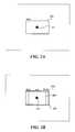
- FIG. 2Dillustrates a display of multiple viewports in portrait mode.
- the viewports 221are in portrait mode and correspond to the viewports of FIG. 2B .
- FIG. 2Eillustrates the display of multiple viewports in both landscape mode and portrait mode.
- the viewports 221are in portrait mode, and the corresponding viewports 222 are in landscape mode.
- the planning systemmay allow all the viewports to be adjusted (e.g., moved and resized) simultaneously as a group. Alternatively, the planning system may allow the landscape mode viewports to be moved or resized separately from the portrait mode viewports.
- FIG. 2Fillustrates multiple viewports that do not share a centerpoint. In this example, a 16:9 viewport, a 16:10 viewport, and a 4:3 viewport share the same upper-right corner and thus do not share the same center point.
- FIG. 3illustrates a display page for setting a pan path in one embodiment.
- the start viewport 301 and the end viewport 302are connected via a line 303 .
- the lineis displayed as a straight line between the center point of the start viewport and the center point of the end viewport.
- the lineincludes control points 304 and 305 .
- the straight line between the center pointsindicates the default pan path in one embodiment.
- a usermay select the control points to alter the pan path. In this example, the user has selected control point 305 and moved it to the lower right and has selected control point 304 and moved it to the upper left to effect an “S” pan path.
- the control points and the center pointsmay be curve fitted using a spline curve.
- the pan pathmay be specified by an arbitrary function. For example, if the center point of the end viewport is the center of the image, then a spiral pan path function may be used as to show the viewport spiraling in towards the center of the image.
- complex zooming and panningmay be effected by a sequence of viewports over the same image.
- the usermay specify a start and end viewport along with intermediate viewports of an image and an arbitrary pan path between each pair of successive viewports.
- a similar effectmay be obtained by having a plan with duplicate images in which the end viewport in one image is the start viewport of the duplicate image.
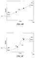
- FIGS. 4A-4Cillustrate display pages for setting the pan speed in one embodiment.
- FIG. 4Aillustrates a display page with a constant pan speed specified.
- the display pageincludes a start viewport 401 and an end viewport 402 connected by a speed line 403 .
- the speed linerepresents speed in the y coordinate 451 as a function of time in the x coordinate 452 .
- the x coordinaterepresents the pan time (e.g., 15 minutes) to pan from the start viewport to the end viewport over the pan path. In this example, since the line is horizontal, the pan speed is constant over the pan time.
- FIG. 4Billustrates a display page with a linearly increasing pan speed.
- the start viewport 421is positioned at a low speed and at the end viewport 422 is positioned at a high speed.
- Line 423illustrates the increase in pan speed when panning from the start viewport to the end viewport.
- a usermay move the start viewport or the end viewport up or down to change the acceleration of the panning.
- FIG. 4Cillustrates a display page with an acceleration that varies non-linearly over the pan time.
- the start viewport 431is positioned at a low speed
- the end viewport 432is positioned at a high speed.
- the line 433was initially a straight line between the start viewport and the end viewport.
- a usermoved control points 434 and 435 to alter the shape of the line (including its slope) and thus the pan speed over the pan time.
- the planning systemadjusts the speed function so that the average speed of the panning is maintained.
- the zoom speedcan be specified by a user in a similar manner. Also, a user may provide an arbitrary function to control the pan and zoom speeds.
- Table 1provides a sample plan document in XML format. This sample plan specifies to transition into “image1” and display for 900 seconds, to fade into “image2” and then pan around “image2” for 900 seconds, and to fade into “image3” and then hold for 900 seconds.
- the first xfade elementindicates to transition over 5 seconds from the current screen image to the “image” at offset 0,0 with a width of 1366 and height of 768 (i.e., 16:9 aspect ratio) and hold for 900 seconds.
- the second xfade elementindicates to transition over 5 seconds from the current image (i.e., “image1”) to “image2” at offset 24,68 and hold for 5 seconds.
- the pan elementindicates to pan over 900 seconds from the start viewport (i.e.
- the display elementindicates to display the current image (i.e., “image2”) at the offsets (i.e., panned to location) for 5 seconds.
- the last xfade elementindicates to transition over 5 seconds to “image3” at offset 0,0 and hold for 900 seconds.
- the backgroundcolor elementspecifies the color of the matte.
- the group elementis used for defining a group of images.
- the info elementis used to specify the information of the text field.
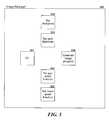
- FIG. 5is a block diagram illustrating components of the planning system in one embodiment.
- the planning system 500includes a user interface component 501 , a set viewports component 502 , a set pan path function component 503 , a set pan speed function component 504 , a set zoom speed function component 505 , and a publish image plan component 506 .
- the user interface componentreceives user commands, invokes the appropriate components to perform those commands, and updates the display accordingly.
- the set viewport componentcontrols the establishing of the viewport including the position and size of the viewports.
- the set pan path function componentcontrols the setting of the pan path between the start viewport and the end viewport. In one embodiment, the component initially displays a straight line with control points between the center points of the start viewport and the end viewport.
- the usercan then move the control points to change the shape of line with the resulting function defining the pan path between the start viewport and the end viewport.
- the pathis defined by a spline curve based on the position of control points.
- the set pan speed function componentdisplays a representation of the start viewport and the end viewport relative to a speed axis and a time axis.
- the time axisrepresents the pan time (e.g., 15 minutes), and the speed axis represents the speed of the pan over the pan time.
- the average pan speedis the pan distance (e.g., in number of pixels) as defined by the pan path function divided by the pan time, regardless of the specified pan speed function.
- the pan speed functionspecifies a relative speed, rather than an absolute speed.
- the set zoom speed function componentoperates in a similar manner to the set pan speed function component except for controlling the zoom speed.
- the planning systemmay also have a set zoom size function component that is used to specify the zoom size during zooming.
- a usermay specify the zoom size by changing the shape of a line connecting an indication of the start and end viewports that is displayed on a coordinate system with the x-axis representing zoom time and the y-axis representing zoom size.
- the sizes of the indicators of the start and end viewportsmay represent the relative sizes of the viewports themselves and may include the content of the viewport.
- the planning systemmay execute on a computer system that includes a central processing unit, memory, input devices (e.g., keyboard and pointing devices), output devices (e.g., display devices), and storage devices (e.g., disk drives).
- the memory and storage devicesare computer-readable media that may contain instructions that implement the planning system.
- the data structures and message structuresmay be stored or transmitted via a data transmission medium, such as a signal on a communications link.
- Various communications linksmay be used, such as the Internet, a local area network, a wide area network, or a point-to-point dial-up connection for distribution of the plan documents.
- FIG. 6is a flow diagram illustrating the processing of the set viewports component in one embodiment.
- the componentcontrols the positioning and sizing of the start and end viewports.
- the componentmay also allow the user to specify viewports with different aspect ratios that can be moved and resized as a group.
- the componentallows a user to specify the relative position of the viewports with different aspect ratios. For example, a relative position may indicate that all the viewports share the same center point, the same corner point, and so on.
- the componentdisplays an outline of the start viewport.
- the start and end viewportsmay have initial sizes and positions specified by the planning system.
- the componentdisplays an outline of the end viewport.
- the componentmay display the viewports using different attributes (e.g., different colors) to distinguish the start viewport from the end viewport.
- the viewportscan be of an arbitrary shape such as rectangular, circular, heart, star, and so on.
- an interpolation functionmay be used to define the viewport shape as it transitions from the start viewport shape to the end viewport shape.
- the componentreceives user input.
- decision block 604if the user indicates to resize a viewport, then the component continues at block 605 to control the resizing of the viewport and then loops to block 601 , else the component continues at block 606 .
- decision block 606if the user specifies to move a viewport, then the component continues at block 607 to control the moving of the viewport and loops to block 601 , else the component continues at block 608 .
- decision block 608if the user specifies completion of the manipulation of the viewports, then the component completes, else the component performs other processing specified by the user such as changing the attributes or shape of a viewport as indicated by the ellipses.
- FIG. 7is a flow diagram illustrating the processing of the display outline component in one embodiment.
- the componentdisplays outlines representing viewports with different aspect ratios at a common center point.
- the componentis passed an indication of the center point and the number of pixels per unit of an aspect ratio.
- the componentloops selecting and displaying the outline for each aspect ratio.
- the componentselects the next aspect ratio.
- decision block 702if all the aspect ratios already been selected, then the component returns, else the component continues at block 703 .
- the componentsets the x coordinate of the upper-left location of the viewport to the x coordinate of the center point minus one half of the x value of the aspect ratio times the number of pixels per aspect ratio unit. For example, if the x coordinate of the center point is 100, the aspect ratio is 16:9, and the pixels per unit are 5, then the x coordinate of the upper-left corner of the rectangular viewport is 60 (e.g., 100 ⁇ (0.5*16*5)).
- the componentsets the y coordinate of the upper-left corner of the viewport to the y coordinate of the center point minus one half of the y value of the aspect ratio times the number of pixels per aspect ratio unit.
- the componentdraws the outline of the viewport positioned at the designated upper-left corner and loops to block 701 to select the next aspect ratio.
- FIG. 8is a flow diagram illustrating the setting of the color of the matte in one embodiment.
- the componentis passed an indication of the area of the image from which the color is to be derived.
- the componentaverages the color values of the pixels within that area and uses that average color as the color of the matte.
- the componentselects the next row of the image area.
- decision block 802if all the rows have already been selected, then the component continues at block 807 , else the component continues at block 803 .
- the componentselects the next column of the selected row.
- decision block 804if all the columns of the selected row have already been selected, then the component loops to block 801 to select the next row, else the component continues at block 805 .
- the componentadds the color of the pixel indicated by the selected row and the selected column to a running total of the color values of the pixels. In one embodiment, the component calculates a separate total for the each component of the color, such as red, green, and blue components.
- the componentincrements the number of pixels in the area and then loops to block 803 to select the next column within the selected row.
- the componentcalculates the color of the matte by dividing the sum of the colors by the number of pixels and then returns.
- the planning systemmay allow a user to specify rules for selecting the color of the matte that is to be displayed when an image is displayed.
- the planning systemmay also allow a user to specify the area of the image from which the matte color is automatically derived, or the planning system may automatically select the area.
- the automatic selectionmay, for example, use an algorithm to identify the area surrounding the subject of the image or to identify background area.
- the rulesmay specify to select a complimentary color to the average color of the subject area, to not allow certain colors (e.g., brown) to be the matte color, and so on; the matte color may also change as the image is panned.
- the matte colormay be the average color of the current viewport.
- FIG. 9is a flow diagram illustrating the processing of the set path function component in one embodiment.
- the componentis passed an indication of the image and the start and end viewports.
- the componentallows the user to manipulate the control points of a line defining the pan path that extends from the center of the start viewport to the center of the end viewport.
- the componentdisplays the image.
- the componentdisplays the start viewport.
- the componentdisplays the end viewport.
- the componentdisplays a line connecting the center points of the start and end viewports.
- the linemay include handles representing control points for controlling the shape of the pan path.
- the componentreceives the adjustments for the control points.
- the componentthen returns the function defining the pan path as defined by the position of the control points.
- FIG. 10is a flow diagram representing the processing of the set pan speed function component in one embodiment.
- the componentdisplays an indication of a speed-versus-time coordinate system and allows the user to define a function specifying the speed of the pan over time.
- the componentdisplays a start viewport indicator corresponding to a time of zero.
- the componentdisplays an end viewport indicator corresponding to the pan time.
- the componentdisplays a line connecting the start viewport and the end viewport. The connecting line is initially horizontal to indicate a constant speed of the pan.
- the componentallows the user to set the start speed by moving the start viewport to a faster or slower speed.
- the componentallows the user to set pan the end pan speed by allowing the user to move the end viewport indicator to a different speed.
- the componentallows a user to adjust the positions of the control points of the line to specify the speed function. The component then returns the pan speed function based on the position of the control points.
- a component for specifying a zoom speed functionwould operate in a similar manner.
- the color of the line representing a pan pathmay be varied to represent the pan speed along the pan path. For example, high intensity yellow may represent a slow pan speed, high intensity green may represent the average pan speed, and high intensity blue may represent a fast pan speed.
- the thickness of the linemay represent the zoom speed or the size of the viewport.
- the contents of each aspect ratio of a viewportmay be displayed separately from the displayed image so that a user can see what the contents of each aspect ratio will look like separately.
- the planning systemmay also define the functions for pan path, pan speed, zoom speed, and zoom size by a map of discreet values such as zoom size to zoom speed.
- the controllermay enlarge the content of each viewport to fill the display or may display the content of each viewport with a size based on the relative viewport sizes.
- Zoomingrefers to changes in viewport size, regardless of the size at which the content of a viewport is ultimately displayed. Accordingly, the invention is not limited except by the appended claims.
Landscapes
- Engineering & Computer Science (AREA)
- Theoretical Computer Science (AREA)
- Physics & Mathematics (AREA)
- General Physics & Mathematics (AREA)
- General Engineering & Computer Science (AREA)
- Human Computer Interaction (AREA)
- Multimedia (AREA)
- Controls And Circuits For Display Device (AREA)
Abstract
Description
| U.S. application Ser. No. | Title |
| 10/704,339 | Method and System for Specifying a Pan Path |
| 10/704,185 | Method and System for Specifying Pan Speed |
| 10/704,212 | Method and System for Specifying Zoom |
| Speed | |
| 10/704,186 | Method and System for Specifying Zoom Size |
| 10/703,407 | Method and System for Specifying Color of a |
| Fill Area | |
| 10/704,378 | Method and System for Generating Image |
| Display Plans | |
| TABLE 1 | ||
| <?xml version=“1.0” encoding=“utf-8” ?> | ||
| <RGBImageScript> | ||
| <Xfade> | ||
| <Group></Group> | ||
| <Duration>5</Duration> | ||
| <Hold>900</Hold> | ||
| <Width>1366</Width> | ||
| <Height>768</Height> | ||
| <OffsetX>0</OffsetX> | ||
| <OffsetY>0</OffsetY> | ||
| <StartImage> | ||
| <Path>Screen</Path> | ||
| </StartImage> | ||
| <EndImage> | ||
| <Path> (16x9) Image1.tif</Path> | ||
| <BackgroundColor>0x617082</BackgroundColor> | ||
| </EndImage> | ||
| <Info></Info> | ||
| </Xfade> | ||
| <Xfade> | ||
| <Group></Group> | ||
| <Duration>5</Duration> | ||
| <Hold>5</Hold> | ||
| <Width>1366</Width> | ||
| <Height>768</Height> | ||
| <OffsetX>26</OffsetX> | ||
| <OffsetY>68</OffsetY> | ||
| <StartImage> | ||
| <Path>Screen</Path> | ||
| </StartImage> | ||
| <EndImage> | ||
| <Path> (16x9) Image2.tif</Path> | ||
| <BackgroundColor>0x637690</BackgroundColor> | ||
| </EndImage> | ||
| <Info></Info> | ||
| </Xfade> | ||
| <Pan> | ||
| <Group></Group> | ||
| <Duration>900</Duration> | ||
| <StartX>26</StartX> | ||
| <StartY>68</StartY> | ||
| <EndX>3610</EndX> | ||
| <EndY>3026</EndY> | ||
| <StartWidth>1366</StartWidth> | ||
| <EndWidth>1366</EndWidth> | ||
| <StartHeight>768</StartHeight> | ||
| <EndHeight>768</EndHeight> | ||
| <RGBImage> | ||
| <BackgroundColor>0x637690</BackgroundColor> | ||
| <Path> (16x9) Image2.tif</Path> | ||
| </RGBImage> | ||
| <Info></Info> | ||
| </Pan> | ||
| <Display> | ||
| <Group></Group> | ||
| <Duration>5</Duration> | ||
| <Width>1366</Width> | ||
| <Height>768</Height> | ||
| <OffsetX>3610</OffsetX> | ||
| <OffsetY>3026</OffsetY> | ||
| <RGBImage> | ||
| <Path>Screen</Path> | ||
| <BackgroundColor>0x637690</BackgroundColor> | ||
| </RGBImage> | ||
| <Info></Info> | ||
| </Display> | ||
| <Xfade> | ||
| <Group></Group> | ||
| <Duration>5</Duration> | ||
| <Hold>900</Hold> | ||
| <Width>1364</Width> | ||
| <Height>768</Height> | ||
| <OffsetX>0</OffsetX> | ||
| <OffsetY>0</OffsetY> | ||
| <StartImage> | ||
| <Path>Screen</Path> | ||
| </StartImage> | ||
| <EndImage> | ||
| <Path> (16x9) Image3.tif</Path> | ||
| <BackgroundColor>0x473522</BackgroundColor> | ||
| </EndImage> | ||
| <Info></Info> | ||
| </Xfade> | ||
| </RGBImageScript> | ||
Claims (48)
Priority Applications (1)
| Application Number | Priority Date | Filing Date | Title |
|---|---|---|---|
| US10/704,211US8739060B2 (en) | 2003-09-29 | 2003-11-07 | Method and system for displaying multiple aspect ratios of a viewport |
Applications Claiming Priority (2)
| Application Number | Priority Date | Filing Date | Title |
|---|---|---|---|
| US10/675,925US8949380B2 (en) | 2003-09-29 | 2003-09-29 | Method and system for distributing images to client systems |
| US10/704,211US8739060B2 (en) | 2003-09-29 | 2003-11-07 | Method and system for displaying multiple aspect ratios of a viewport |
Related Parent Applications (1)
| Application Number | Title | Priority Date | Filing Date |
|---|---|---|---|
| US10/675,925Continuation-In-PartUS8949380B2 (en) | 2003-09-29 | 2003-09-29 | Method and system for distributing images to client systems |
Publications (2)
| Publication Number | Publication Date |
|---|---|
| US20050071774A1 US20050071774A1 (en) | 2005-03-31 |
| US8739060B2true US8739060B2 (en) | 2014-05-27 |
Family
ID=46301694
Family Applications (1)
| Application Number | Title | Priority Date | Filing Date |
|---|---|---|---|
| US10/704,211Expired - LifetimeUS8739060B2 (en) | 2003-09-29 | 2003-11-07 | Method and system for displaying multiple aspect ratios of a viewport |
Country Status (1)
| Country | Link |
|---|---|
| US (1) | US8739060B2 (en) |
Cited By (3)
| Publication number | Priority date | Publication date | Assignee | Title |
|---|---|---|---|---|
| US20150363082A1 (en)* | 2014-06-17 | 2015-12-17 | Vmware, Inc. | User interface control based on pinch gestures |
| WO2017196131A1 (en)* | 2016-05-12 | 2017-11-16 | Samsung Electronics Co., Ltd. | Method and apparatus for providing content navigation |
| USD812075S1 (en)* | 2014-11-21 | 2018-03-06 | Mitsubishi Electric Corporation | Building monitoring display with graphical user interface |
Families Citing this family (33)
| Publication number | Priority date | Publication date | Assignee | Title |
|---|---|---|---|---|
| JP4465142B2 (en)* | 2002-01-30 | 2010-05-19 | 富士通株式会社 | Window display control program, window display control method, and window display control device |
| US7532753B2 (en) | 2003-09-29 | 2009-05-12 | Lipsky Scott E | Method and system for specifying color of a fill area |
| US20060004697A1 (en)* | 2004-06-09 | 2006-01-05 | Lipsky Scott E | Method and system for restricting the display of images |
| US20060070001A1 (en)* | 2004-09-29 | 2006-03-30 | Fuji Xerox Co., Ltd. | Computer assisted presentation authoring for multimedia venues |
| US7752548B2 (en)* | 2004-10-29 | 2010-07-06 | Microsoft Corporation | Features such as titles, transitions, and/or effects which vary according to positions |
| US7710423B2 (en)* | 2005-03-21 | 2010-05-04 | Microsoft Corproation | Automatic layout of items along an embedded one-manifold path |
| JP2007025862A (en)* | 2005-07-13 | 2007-02-01 | Sony Computer Entertainment Inc | Image processor |
| US7639873B2 (en)* | 2005-07-28 | 2009-12-29 | Microsoft Corporation | Robust shot detection in a video |
| US7739599B2 (en)* | 2005-09-23 | 2010-06-15 | Microsoft Corporation | Automatic capturing and editing of a video |
| US20070083821A1 (en)* | 2005-10-07 | 2007-04-12 | International Business Machines Corporation | Creating viewports from selected regions of windows |
| US7644364B2 (en)* | 2005-10-14 | 2010-01-05 | Microsoft Corporation | Photo and video collage effects |
| US7274377B2 (en)* | 2005-10-28 | 2007-09-25 | Seiko Epson Corporation | Viewport panning feedback system |
| USD546834S1 (en)* | 2005-11-16 | 2007-07-17 | Microsoft Corporation | Icon for a portion of a display screen |
| US7945142B2 (en)* | 2006-06-15 | 2011-05-17 | Microsoft Corporation | Audio/visual editing tool |
| US20080100642A1 (en)* | 2006-10-31 | 2008-05-01 | International Business Machines Corporation | User definable aspect ratios for image regions |
| KR101411324B1 (en)* | 2007-08-14 | 2014-06-25 | 삼성전자주식회사 | Image display method and display device using the method |
| US8335996B2 (en)* | 2008-04-10 | 2012-12-18 | Perceptive Pixel Inc. | Methods of interfacing with multi-input devices and multi-input display systems employing interfacing techniques |
| KR20140147136A (en)* | 2008-04-15 | 2014-12-29 | 오페라 소프트웨어 에이에스에이 | Method and device for dynamically wrapping text when displaying a selected region of an electronic document |
| US9310907B2 (en) | 2009-09-25 | 2016-04-12 | Apple Inc. | Device, method, and graphical user interface for manipulating user interface objects |
| WO2011037558A1 (en) | 2009-09-22 | 2011-03-31 | Apple Inc. | Device, method, and graphical user interface for manipulating user interface objects |
| US8832585B2 (en) | 2009-09-25 | 2014-09-09 | Apple Inc. | Device, method, and graphical user interface for manipulating workspace views |
| US8766928B2 (en)* | 2009-09-25 | 2014-07-01 | Apple Inc. | Device, method, and graphical user interface for manipulating user interface objects |
| US8799826B2 (en)* | 2009-09-25 | 2014-08-05 | Apple Inc. | Device, method, and graphical user interface for moving a calendar entry in a calendar application |
| US8381125B2 (en)* | 2009-12-16 | 2013-02-19 | Apple Inc. | Device and method for resizing user interface content while maintaining an aspect ratio via snapping a perimeter to a gridline |
| US8612884B2 (en) | 2010-01-26 | 2013-12-17 | Apple Inc. | Device, method, and graphical user interface for resizing objects |
| US8539385B2 (en)* | 2010-01-26 | 2013-09-17 | Apple Inc. | Device, method, and graphical user interface for precise positioning of objects |
| US8539386B2 (en)* | 2010-01-26 | 2013-09-17 | Apple Inc. | Device, method, and graphical user interface for selecting and moving objects |
| US8972879B2 (en) | 2010-07-30 | 2015-03-03 | Apple Inc. | Device, method, and graphical user interface for reordering the front-to-back positions of objects |
| US9081494B2 (en) | 2010-07-30 | 2015-07-14 | Apple Inc. | Device, method, and graphical user interface for copying formatting attributes |
| US9098182B2 (en) | 2010-07-30 | 2015-08-04 | Apple Inc. | Device, method, and graphical user interface for copying user interface objects between content regions |
| JP5882975B2 (en)* | 2012-12-26 | 2016-03-09 | キヤノン株式会社 | Image processing apparatus, imaging apparatus, image processing method, and recording medium |
| US9703757B2 (en)* | 2013-09-30 | 2017-07-11 | Google Inc. | Automatically determining a size for a content item for a web page |
| USD983817S1 (en)* | 2021-02-16 | 2023-04-18 | Kimberly-Clark Worldwide, Inc. | Package with surface ornamentation or display screen with icon |
Citations (32)
| Publication number | Priority date | Publication date | Assignee | Title |
|---|---|---|---|---|
| US4189743A (en) | 1976-12-20 | 1980-02-19 | New York Institute Of Technology | Apparatus and method for automatic coloration and/or shading of images |
| US4533910A (en)* | 1982-11-02 | 1985-08-06 | Cadtrak Corporation | Graphics display system with viewports of arbitrary location and content |
| US4642790A (en)* | 1983-03-31 | 1987-02-10 | International Business Machines Corporation | Presentation space management and viewporting on a multifunction virtual terminal |
| US4872056A (en) | 1987-02-05 | 1989-10-03 | Video Graphic Styling, Inc. | Method for displaying selected hairstyles in video form |
| US4982345A (en)* | 1989-01-23 | 1991-01-01 | International Business Machines Corporation | Interactive computer graphics display system processing method for identifying an operator selected displayed object |
| US5093717A (en) | 1987-08-03 | 1992-03-03 | American Film Technologies, Inc. | System and method for digitally coloring images |
| JPH04205484A (en) | 1990-11-30 | 1992-07-27 | Daikin Ind Ltd | Edge-enhanced polygon filling method and device |
| US5428721A (en) | 1990-02-07 | 1995-06-27 | Kabushiki Kaisha Toshiba | Data processing apparatus for editing image by using image conversion |
| US5506946A (en) | 1991-10-01 | 1996-04-09 | Electronics For Imaging, Inc. | Selective color correction |
| US5630037A (en) | 1994-05-18 | 1997-05-13 | Schindler Imaging, Inc. | Method and apparatus for extracting and treating digital images for seamless compositing |
| US5841883A (en) | 1994-10-27 | 1998-11-24 | Yazaki Corporation | Method of diagnosing a plant automatically and device for executing method thereof |
| US5929867A (en) | 1996-08-07 | 1999-07-27 | Adobe System Incorporated | Floating keyframes |
| US5995194A (en) | 1996-12-26 | 1999-11-30 | Fuji Photo Film Co., Ltd. | Reproducing machine and a method of determining reproducing conditions |
| US6012071A (en)* | 1996-01-29 | 2000-01-04 | Futuretense, Inc. | Distributed electronic publishing system |
| US6014464A (en) | 1997-10-21 | 2000-01-11 | Kurzweil Educational Systems, Inc. | Compression/ decompression algorithm for image documents having text graphical and color content |
| US6587119B1 (en)* | 1998-08-04 | 2003-07-01 | Flashpoint Technology, Inc. | Method and apparatus for defining a panning and zooming path across a still image during movie creation |
| US6628283B1 (en)* | 2000-04-12 | 2003-09-30 | Codehorse, Inc. | Dynamic montage viewer |
| US20040095375A1 (en)* | 2002-05-10 | 2004-05-20 | Burmester Christopher Paul | Method of and apparatus for interactive specification of manufactured products customized with digital media |
| US6768488B1 (en) | 1999-05-25 | 2004-07-27 | Nippon Telegraph And Telephone Corporation | Image filling method, apparatus and computer readable medium for reducing filling process in processing animation |
| US20040239681A1 (en) | 2000-08-07 | 2004-12-02 | Zframe, Inc. | Visual content browsing using rasterized representations |
| US20040268413A1 (en) | 2003-05-29 | 2004-12-30 | Reid Duane M. | System for presentation of multimedia content |
| US20050081247A1 (en) | 2003-09-29 | 2005-04-14 | Lipsky Scott E. | Method and system for generating image display plans |
| US6956589B2 (en) | 2003-09-29 | 2005-10-18 | Beon Media Inc. | Method and system for specifying zoom size |
| US6987522B2 (en) | 2003-09-29 | 2006-01-17 | Beon Media Inc. | Method and system for specifying pan speed |
| US6989848B2 (en) | 2003-09-29 | 2006-01-24 | Beon Media Inc. | Method and system for specifying zoom speed |
| US7043465B2 (en) | 2000-02-24 | 2006-05-09 | Holding B.E.V.S.A. | Method and device for perception of an object by its shape, its size and/or its orientation |
| US7050072B2 (en) | 2003-09-29 | 2006-05-23 | Galleryplayer, Inc. | Method and system for specifying a pan path |
| US7133571B2 (en)* | 2000-12-22 | 2006-11-07 | Hewlett-Packard Development Company, L.P. | Automated cropping of electronic images |
| US7190844B2 (en) | 2002-02-22 | 2007-03-13 | Konica Corporation | Image processing method, storage medium, image processor and image recorder |
| US7305146B2 (en)* | 2001-06-30 | 2007-12-04 | Hewlett-Packard Development Company, L.P. | Tilt correction of electronic images |
| US7324246B2 (en) | 2001-09-27 | 2008-01-29 | Fujifilm Corporation | Apparatus and method for image processing |
| US7532753B2 (en) | 2003-09-29 | 2009-05-12 | Lipsky Scott E | Method and system for specifying color of a fill area |
- 2003
- 2003-11-07USUS10/704,211patent/US8739060B2/ennot_activeExpired - Lifetime
Patent Citations (36)
| Publication number | Priority date | Publication date | Assignee | Title |
|---|---|---|---|---|
| US4189743A (en) | 1976-12-20 | 1980-02-19 | New York Institute Of Technology | Apparatus and method for automatic coloration and/or shading of images |
| US4533910A (en)* | 1982-11-02 | 1985-08-06 | Cadtrak Corporation | Graphics display system with viewports of arbitrary location and content |
| US4642790A (en)* | 1983-03-31 | 1987-02-10 | International Business Machines Corporation | Presentation space management and viewporting on a multifunction virtual terminal |
| US4872056A (en) | 1987-02-05 | 1989-10-03 | Video Graphic Styling, Inc. | Method for displaying selected hairstyles in video form |
| US5093717A (en) | 1987-08-03 | 1992-03-03 | American Film Technologies, Inc. | System and method for digitally coloring images |
| US4982345A (en)* | 1989-01-23 | 1991-01-01 | International Business Machines Corporation | Interactive computer graphics display system processing method for identifying an operator selected displayed object |
| US5428721A (en) | 1990-02-07 | 1995-06-27 | Kabushiki Kaisha Toshiba | Data processing apparatus for editing image by using image conversion |
| JPH04205484A (en) | 1990-11-30 | 1992-07-27 | Daikin Ind Ltd | Edge-enhanced polygon filling method and device |
| US5506946A (en) | 1991-10-01 | 1996-04-09 | Electronics For Imaging, Inc. | Selective color correction |
| US5630037A (en) | 1994-05-18 | 1997-05-13 | Schindler Imaging, Inc. | Method and apparatus for extracting and treating digital images for seamless compositing |
| US5841883A (en) | 1994-10-27 | 1998-11-24 | Yazaki Corporation | Method of diagnosing a plant automatically and device for executing method thereof |
| US6012071A (en)* | 1996-01-29 | 2000-01-04 | Futuretense, Inc. | Distributed electronic publishing system |
| US5929867A (en) | 1996-08-07 | 1999-07-27 | Adobe System Incorporated | Floating keyframes |
| US5995194A (en) | 1996-12-26 | 1999-11-30 | Fuji Photo Film Co., Ltd. | Reproducing machine and a method of determining reproducing conditions |
| US6014464A (en) | 1997-10-21 | 2000-01-11 | Kurzweil Educational Systems, Inc. | Compression/ decompression algorithm for image documents having text graphical and color content |
| US6246791B1 (en) | 1997-10-21 | 2001-06-12 | Lernout & Hauspie Speech Products Nv | Compression/decompression algorithm for image documents having text, graphical and color content |
| US6320982B1 (en) | 1997-10-21 | 2001-11-20 | L&H Applications Usa, Inc. | Compression/decompression algorithm for image documents having text, graphical and color content |
| US6587119B1 (en)* | 1998-08-04 | 2003-07-01 | Flashpoint Technology, Inc. | Method and apparatus for defining a panning and zooming path across a still image during movie creation |
| US7102649B2 (en) | 1999-05-25 | 2006-09-05 | Nippon Telegraph And Telephone Corporation | Image filling method, apparatus and computer readable medium for reducing filling process in processing animation |
| US6768488B1 (en) | 1999-05-25 | 2004-07-27 | Nippon Telegraph And Telephone Corporation | Image filling method, apparatus and computer readable medium for reducing filling process in processing animation |
| US7043465B2 (en) | 2000-02-24 | 2006-05-09 | Holding B.E.V.S.A. | Method and device for perception of an object by its shape, its size and/or its orientation |
| US6628283B1 (en)* | 2000-04-12 | 2003-09-30 | Codehorse, Inc. | Dynamic montage viewer |
| US20040239681A1 (en) | 2000-08-07 | 2004-12-02 | Zframe, Inc. | Visual content browsing using rasterized representations |
| US7133571B2 (en)* | 2000-12-22 | 2006-11-07 | Hewlett-Packard Development Company, L.P. | Automated cropping of electronic images |
| US7305146B2 (en)* | 2001-06-30 | 2007-12-04 | Hewlett-Packard Development Company, L.P. | Tilt correction of electronic images |
| US7324246B2 (en) | 2001-09-27 | 2008-01-29 | Fujifilm Corporation | Apparatus and method for image processing |
| US7190844B2 (en) | 2002-02-22 | 2007-03-13 | Konica Corporation | Image processing method, storage medium, image processor and image recorder |
| US20040095375A1 (en)* | 2002-05-10 | 2004-05-20 | Burmester Christopher Paul | Method of and apparatus for interactive specification of manufactured products customized with digital media |
| US20040268413A1 (en) | 2003-05-29 | 2004-12-30 | Reid Duane M. | System for presentation of multimedia content |
| US7050072B2 (en) | 2003-09-29 | 2006-05-23 | Galleryplayer, Inc. | Method and system for specifying a pan path |
| US6989848B2 (en) | 2003-09-29 | 2006-01-24 | Beon Media Inc. | Method and system for specifying zoom speed |
| US6987522B2 (en) | 2003-09-29 | 2006-01-17 | Beon Media Inc. | Method and system for specifying pan speed |
| US6956589B2 (en) | 2003-09-29 | 2005-10-18 | Beon Media Inc. | Method and system for specifying zoom size |
| US20050081247A1 (en) | 2003-09-29 | 2005-04-14 | Lipsky Scott E. | Method and system for generating image display plans |
| US7532753B2 (en) | 2003-09-29 | 2009-05-12 | Lipsky Scott E | Method and system for specifying color of a fill area |
| US7957587B2 (en) | 2003-09-29 | 2011-06-07 | Eqapez Foundation, L.L.C. | Method and system for specifying color of a fill area |
Non-Patent Citations (16)
| Title |
|---|
| "Microsoft Computer Dictionary, 5th Edition", 2002, pp. 37, Microsoft Press. |
| O'Shea, J., "Power Point 97 Introduction (Windows 95) ActiveLearn Series", Ziff-Davis Education, Student Manual, 1998, (8 pages). |
| United States Patent and Trademark Office, Final Office Action, U.S. Appl. No. 10/703,407, mailed Jul. 9, 2008, 10 pages. |
| United States Patent and Trademark Office, Non-Final Office Action, U.S. Appl. No. 10/703,407, mailed Apr. 19, 2007, 8 pages. |
| United States Patent and Trademark Office, Non-Final Office Action, U.S. Appl. No. 10/703,407, mailed Nov. 27, 2007, 7 pages. |
| United States Patent and Trademark Office, Non-Final Office Action, U.S. Appl. No. 10/704,185, mailed May 6, 2005, 7 pages. |
| United States Patent and Trademark Office, Non-Final Office Action, U.S. Appl. No. 10/704,212, mailed May 5, 2005, 7 pages. |
| United States Patent and Trademark Office, Non-Final Office Action, U.S. Appl. No. 10/704,339, mailed May 6, 2005, 17 pages. |
| United States Patent and Trademark Office, Non-Final Office Action, U.S. Appl. No. 10/704,378, mailed Apr. 19, 2005, 11 pages. |
| United States Patent and Trademark Office, Non-Final Office Action, U.S. Appl. No. 12/414,599, mailed Sep. 3, 2010, 6 pages. |
| United States Patent and Trademark Office, Notice of Allowance, U.S. Appl. No. 10/703,407, mailed Dec. 30, 2008, 8 pages. |
| United States Patent and Trademark Office, Notice of Allowance, U.S. Appl. No. 10/704,185, mailed Aug. 26, 2005, 4 pages. |
| United States Patent and Trademark Office, Notice of Allowance, U.S. Appl. No. 10/704,186, mailed May 10, 2005, 12 pages. |
| United States Patent and Trademark Office, Notice of Allowance, U.S. Appl. No. 10/704,212, mailed Aug. 26, 2005, 4 pages. |
| United States Patent and Trademark Office, Notice of Allowance, U.S. Appl. No. 10/704,339, mailed Oct. 24, 2005, 10 pages. |
| United States Patent and Trademark Office, Notice of Allowance, U.S. Appl. No. 12/414,599, mailed Feb. 22, 2011, 6 pages. |
Cited By (5)
| Publication number | Priority date | Publication date | Assignee | Title |
|---|---|---|---|---|
| US20150363082A1 (en)* | 2014-06-17 | 2015-12-17 | Vmware, Inc. | User interface control based on pinch gestures |
| US10042547B2 (en)* | 2014-06-17 | 2018-08-07 | Vmware, Inc. | User interface control based on pinch gestures |
| USD812075S1 (en)* | 2014-11-21 | 2018-03-06 | Mitsubishi Electric Corporation | Building monitoring display with graphical user interface |
| WO2017196131A1 (en)* | 2016-05-12 | 2017-11-16 | Samsung Electronics Co., Ltd. | Method and apparatus for providing content navigation |
| US10841557B2 (en) | 2016-05-12 | 2020-11-17 | Samsung Electronics Co., Ltd. | Content navigation |
Also Published As
| Publication number | Publication date |
|---|---|
| US20050071774A1 (en) | 2005-03-31 |
Similar Documents
| Publication | Publication Date | Title |
|---|---|---|
| US8739060B2 (en) | Method and system for displaying multiple aspect ratios of a viewport | |
| US7957587B2 (en) | Method and system for specifying color of a fill area | |
| US6956589B2 (en) | Method and system for specifying zoom size | |
| US7050072B2 (en) | Method and system for specifying a pan path | |
| US6989848B2 (en) | Method and system for specifying zoom speed | |
| US9024967B2 (en) | Digital video editing system including multiple viewing windows of a same image | |
| US8578273B2 (en) | Slideshow method for displaying images on a display | |
| US10228832B2 (en) | Grouping with frames to transform display elements within a zooming user interface | |
| EP3041221B1 (en) | Image processing device and image processing program | |
| US20140009502A1 (en) | Image displaying apparatus and image displaying method | |
| US20080055315A1 (en) | Method and System to Establish and Animate a Coordinate System for Content on a Display | |
| US11347380B2 (en) | Adding new slides on a canvas in a zooming user interface | |
| JP2004523036A (en) | Image-based digital representation of landscape | |
| CN118556404B (en) | Machine-implemented method, machine-readable medium, and data processing system | |
| WO2023165301A1 (en) | Content publishing method and apparatus, computer device, and storage medium | |
| CN112565858A (en) | Program editing method and device and program publishing method and device | |
| US20050081247A1 (en) | Method and system for generating image display plans | |
| US6987522B2 (en) | Method and system for specifying pan speed | |
| US8988423B2 (en) | Electronic album generating apparatus, stereoscopic image pasting apparatus, and methods and programs for controlling operation of same | |
| KR101825598B1 (en) | Apparatus and method for providing contents, and computer program recorded on computer readable recording medium for executing the method | |
| GB2397456A (en) | Calculation of the location of a region in frames between two selected frames in which region location is defined | |
| CN112770099B (en) | Multimedia playing method, device, terminal and storage medium | |
| CN110121032A (en) | A kind of method, apparatus, equipment and storage medium showing animation effect | |
| Harder | Creating a Parallax: Bring Your Vintage or Historical Photos to Life | |
| JP2006048151A (en) | Content browsing system, content server, program, and storage medium |
Legal Events
| Date | Code | Title | Description |
|---|---|---|---|
| AS | Assignment | Owner name:RGB LABS, INC., WASHINGTON Free format text:ASSIGNMENT OF ASSIGNORS INTEREST;ASSIGNORS:LIPSKY, SCOTT E.;BROWNLOW, PAUL;REEL/FRAME:015426/0789;SIGNING DATES FROM 20040526 TO 20040527 Owner name:RGB LABS, INC., WASHINGTON Free format text:ASSIGNMENT OF ASSIGNORS INTEREST;ASSIGNORS:LIPSKY, SCOTT E.;BROWNLOW, PAUL;SIGNING DATES FROM 20040526 TO 20040527;REEL/FRAME:015426/0789 | |
| AS | Assignment | Owner name:BEON MEDIA INC., WASHINGTON Free format text:CHANGE OF NAME;ASSIGNOR:RGB LABS, INC.;REEL/FRAME:016152/0520 Effective date:20040923 | |
| AS | Assignment | Owner name:GALLERYPLAYER, INC., WASHINGTON Free format text:ASSIGNMENT OF ASSIGNORS INTEREST;ASSIGNOR:BEON MEDIA INC.;REEL/FRAME:017087/0571 Effective date:20050927 | |
| AS | Assignment | Owner name:TRIPLEPOINT CAPITAL LLC, CALIFORNIA Free format text:SECURITY AGREEMENT;ASSIGNOR:GALLERYPLAYER, INC.;REEL/FRAME:018816/0444 Effective date:20070126 | |
| AS | Assignment | Owner name:EQAPEZ FOUNDATION, L.L.C., DELAWARE Free format text:AFFIDAVIT OF FORECLOSURE;ASSIGNOR:TRIPLEPOINT CAPITAL LLC;REEL/FRAME:021439/0121 Effective date:20080815 | |
| STCF | Information on status: patent grant | Free format text:PATENTED CASE | |
| AS | Assignment | Owner name:OL SECURITY LIMITED LIABILITY COMPANY, DELAWARE Free format text:MERGER;ASSIGNOR:EQAPEZ FOUNDATION, L.L.C;REEL/FRAME:036807/0020 Effective date:20150826 | |
| MAFP | Maintenance fee payment | Free format text:PAYMENT OF MAINTENANCE FEE, 4TH YEAR, LARGE ENTITY (ORIGINAL EVENT CODE: M1551) Year of fee payment:4 | |
| MAFP | Maintenance fee payment | Free format text:PAYMENT OF MAINTENANCE FEE, 8TH YEAR, LARGE ENTITY (ORIGINAL EVENT CODE: M1552); ENTITY STATUS OF PATENT OWNER: LARGE ENTITY Year of fee payment:8 |