US8738330B1 - Scalable, inert munition data recorder and method to characterize performance of a weapon system - Google Patents
Scalable, inert munition data recorder and method to characterize performance of a weapon systemDownload PDFInfo
- Publication number
- US8738330B1 US8738330B1US13/213,521US201113213521AUS8738330B1US 8738330 B1US8738330 B1US 8738330B1US 201113213521 AUS201113213521 AUS 201113213521AUS 8738330 B1US8738330 B1US 8738330B1
- Authority
- US
- United States
- Prior art keywords
- data recorder
- cartridge
- scalable
- assembly
- data
- Prior art date
- Legal status (The legal status is an assumption and is not a legal conclusion. Google has not performed a legal analysis and makes no representation as to the accuracy of the status listed.)
- Expired - Fee Related, expires
Links
- 238000000034methodMethods0.000titledescription7
- 238000010304firingMethods0.000claimsdescription2
- 238000004806packaging method and processMethods0.000abstractdescription6
- 230000007613environmental effectEffects0.000abstractdescription3
- 230000006870functionEffects0.000abstractdescription3
- 238000005259measurementMethods0.000description5
- 239000002775capsuleSubstances0.000description4
- 230000008569processEffects0.000description3
- 239000011347resinSubstances0.000description3
- 229920005989resinPolymers0.000description3
- 238000013461designMethods0.000description2
- 238000000465mouldingMethods0.000description2
- 238000012805post-processingMethods0.000description2
- 230000000007visual effectEffects0.000description2
- 230000009471actionEffects0.000description1
- 230000009286beneficial effectEffects0.000description1
- 238000006243chemical reactionMethods0.000description1
- 238000013480data collectionMethods0.000description1
- 230000000694effectsEffects0.000description1
- 239000000463materialSubstances0.000description1
- 238000000691measurement methodMethods0.000description1
- 230000007246mechanismEffects0.000description1
- 230000005055memory storageEffects0.000description1
- 238000012986modificationMethods0.000description1
- 230000004048modificationEffects0.000description1
- 238000012545processingMethods0.000description1
- 230000035939shockEffects0.000description1
- 230000003068static effectEffects0.000description1
- 238000012360testing methodMethods0.000description1
- 230000001960triggered effectEffects0.000description1
Images


Classifications
- F—MECHANICAL ENGINEERING; LIGHTING; HEATING; WEAPONS; BLASTING
- F41—WEAPONS
- F41A—FUNCTIONAL FEATURES OR DETAILS COMMON TO BOTH SMALLARMS AND ORDNANCE, e.g. CANNONS; MOUNTINGS FOR SMALLARMS OR ORDNANCE
- F41A31/00—Testing arrangements
- F—MECHANICAL ENGINEERING; LIGHTING; HEATING; WEAPONS; BLASTING
- F41—WEAPONS
- F41A—FUNCTIONAL FEATURES OR DETAILS COMMON TO BOTH SMALLARMS AND ORDNANCE, e.g. CANNONS; MOUNTINGS FOR SMALLARMS OR ORDNANCE
- F41A33/00—Adaptations for training; Gun simulators
- F—MECHANICAL ENGINEERING; LIGHTING; HEATING; WEAPONS; BLASTING
- F42—AMMUNITION; BLASTING
- F42B—EXPLOSIVE CHARGES, e.g. FOR BLASTING, FIREWORKS, AMMUNITION
- F42B12/00—Projectiles, missiles or mines characterised by the warhead, the intended effect, or the material
- F42B12/02—Projectiles, missiles or mines characterised by the warhead, the intended effect, or the material characterised by the warhead or the intended effect
- F42B12/36—Projectiles, missiles or mines characterised by the warhead, the intended effect, or the material characterised by the warhead or the intended effect for dispensing materials; for producing chemical or physical reaction; for signalling ; for transmitting information
- F42B12/365—Projectiles transmitting information to a remote location using optical or electronic means
- F—MECHANICAL ENGINEERING; LIGHTING; HEATING; WEAPONS; BLASTING
- F42—AMMUNITION; BLASTING
- F42B—EXPLOSIVE CHARGES, e.g. FOR BLASTING, FIREWORKS, AMMUNITION
- F42B35/00—Testing or checking of ammunition
Definitions
- the present inventionrelates in general to the field of munitions. More specifically, this invention relates to data acquisition acquired by an ammunition cartridge at firing, exit, and during flight. More specifically this invention pertains to data acquisition within ammunition environments including, but not limited to, the weapon system, ammunition packaging, exposure to meteorological and environmental conditions, and the bare case of the ammunition.
- Useful information about a weapon system and associated ammunitioncan be gathered with external visual observation of the weapon system in action, and the ammunition whether or not it is packaged.
- weapon barrel sensorsrecord chemical reactions that occur in milliseconds of elapsed time.
- the feed mechanism and loading chamber of the weaponare not, however, simply observed or characterized by available measurement techniques.
- the nature of the moving partsprevents a static measurement device from being placed within this part of the weapon.
- the present inventionsatisfies this need, and describes a scalable, inert munition data recorder assembly and method to characterize the performance of a weapon system, ammunition storage, transportation unit, and bare case enclosure.
- the inert data recorder assemblyincludes the following components that are scalable to the weapon system of interest.
- the internal electronic componentsinclude a data sensor, such as one or more 3-axis accelerometer, thermocouple, strain gauge, etc., that is encapsulated in resin and connected to a memory storage device.
- a data interface portallows the cartridge to be connected to a computer.
- An internal power supplypowers the electronic components.
- the housing of the electronic componentssubstantially replicates the outside profile of a cartridge case that is meant to interface with a desired weapon system.
- an inert data recorder built to work with the M242 autogunwill have the outside profile of a 25 mm cartridge.
- the data recordercan be manually, remotely, and/or automatically activated prior to, or at the onset of a data recording session within a weapon system or other ammunition environment.
- an ammunition eventi.e., weapon system activity, ammunition container vibration, ejection from a weapon, etc.
- the data recorderlogs data measurements taken by the internal data sensor.
- the data recorderrecords data from within a weapon loading magazine, weapon chamber, and during ejection from the weapon. Data logging ends when the data recorder is triggered to, or meets the proper criteria to cease recording. Recorded data will be transferred to a computer where post-processing will occur.
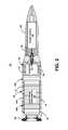
- FIG. 2is a cross-sectional view of the cartridge of FIG. 1 , illustrating the components the data recorder assembly;
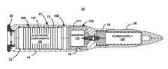
- FIG. 1is a perspective, side elevational view of an exemplary cartridge (also alternatively referred to herein as munition or projectile) 10 containing an inert data recorder assembly 100 ( FIGS. 2 , 3 ) of the present invention.
- the data recorder assembly 100is assembled and fits within a weapon system or ammunition packaging or transportation unit.
- the data recorder assembly 100records data specific to a sensor during a specific weapon operation. This device can be placed or inserted into any location where the non-inert, live cartridge 10 is, or can in the future, be secured.
- the cartridge 10can be used independently to collect data. Although the cartridge 10 is designed to interface with a weapon and ammunition packaging based on its shape, it still functions as designed regardless of its location and application. This would allow the cartridge 10 to be placed anywhere an actual live cartridge of ammunition could be placed.
- the cartridge 10generally includes a casing (or casing assembly) 11 and a data recorder assembly 100 .
- the casing 11is comprised of a body 12 that includes a cover 13 and a housing 14 , a cartridge extractor cap 20 , a nose 50 , and two screw sets 60 , 70 ( FIG. 3 ).
- the inert data recorder assembly 100is generally comprised of an onboard data recorder 160 , a sensor package 170 , a power supply 180 , a data interface port 190 ( FIG. 3 ), and a set of screws 195 ( FIG. 3 ).
- the data recorder assembly 100could be integrated into a single unit where the sensors and memory chips are formed in one package.
- the single unit designwould keep the same function and fit into the cartridge casing 11 described herein, and consequently it would increases space within the casing 11 for multiple sensors or additional batteries (or power supplies).
- the onboard data recorder 160 and the sensor package 170are independently and separately placed in an axially-oriented cavity 15 of the electronic housing 14 . It should however be understood that the onboard data recorder 160 and the sensor package 170 may alternatively be built into the same casing 11 .
- the exterior shape (or profile) of the data recorder 160 and that of the sensor package 170substantially correspond to, or match the interior shape of the cavity 15 , in order to minimize, if not to prevent the movement of the data recorder 160 and the sensor package 170 within the casing 11 .
- the data recorder 160 and the sensor package 170have generally cylindrical shapes that match that of the cavity 15 .
- the cover 13is then fitted to the housing 14 in order to further secure and house the data recorder 160 and the sensor package 170 , within the chamber that is formed by the cavity 15 of the housing 14 , a corresponding (or matching as needed for design purpose) cavity in the cover 13 , and an extension 16 of the housing 14 .
- the housing 14is integrally provided with the generally cylindrically shaped extension 16 that houses, at least in part, the sensor package 170 .
- the extension 16has a generally cylindrically interior shape that substantially matches that of the exterior surface of the sensor package 170 .
- the casing 11includes a forward locking feature 19 that prevents the rotation of the sensor package 170 within the casing 11 .
- FIG. 3illustrates one or more lateral protrusions 23 that project inwardly, in order to prevent the sensor package 170 from sliding, along the axial direction, within the casing 11 .
- the locking feature 19 and the protrusion 23suspend the sensor package 170 with zero degrees of freedom, which is a beneficial feature particularly to a 3-axis accelerometer package where a fixed origin must be maintained for data collection.
- the casing 11further includes locking features to suspend the data recorder 160 with zero degrees of freedom.
- a rearward anti-rotation feature 22that is formed of one or more lateral protrusions that project inwardly, prevents the data recorder 160 from rotating within the casing 11 .
- This anti-rotation feature 22may be used as an alignment reference for the data recorder 160 , allowing the data recorder assembly 100 to be used in any orientation.
- a mid-casing inward lateral protrusion 24prevents sliding of the data recorder 160 in the axial direction along the central axis of the casing 11 .
- the housing 14includes, at its rearward end, a notch 30 that is formed in a rearward wall 31 of the housing 14 , enables access to the data captured by the data recorder assembly 100 .
- a data interface port 190protrudes, in part through the notch 30 and is electrically connected to the onboard data recorder 160 .
- the data interface port 190is secured to the rearward wall 31 by means of, for example, the set of screws 195 .
- the cover 13has a similar feature to that described in connection with the housing 14 to accommodate and secure the data interface port 190 . Once assembled, the data interface port 190 further stabilizes the data recorder 160 securely in position within the casing 11 .
- the sensor package 170generally includes one or more sensors, such as one or more 3D accelerometers and/or other sensors 175 , such as pressure sensors, humidity sensors, temperature, etc.
- the sensors 175are enclosed in a capsule 177 .
- the capsule 177can be formed using, for example, a molding process where the sensors 175 are surrounded by cured resin in a mold, such that the outer profile (i.e., shape and dimensions) of the capsule 177 is substantially similar or identical to the interior of the extension 16 .
- the onboard data recorder 160is the main hub of all internal wiring of the data recorder assembly 100 .
- the onboard data recorder 160generally includes one or more electronic components 165 and wiring that accept, record (or store), and possibly process the data captured by the sensors 175 and transmitted to the onboard data recorder 160 by means of the wiring.
- the onboard data recorder 160further includes a housing 167 that houses the electronic components 165 .
- the housing 167can be formed using, for example, a molding process where the electronic components 165 are surrounded by cured resin in a mold, such that the outside housing 167 shape and dimensions are substantially similar or identical to the interior of the cavity (or chamber) 15 .
- the housing 167 of the onboard data recorder 160 and the capsule 177 of the sensor package 170are generally cylindrically shaped, and have substantially equal radii. As a result, upon assembly of the onboard data recorder 160 and the sensor package 170 within the casing 11 , the exterior surface of the assembly fits within the cavity 15 of the casing 11 .
- the onboard data recorder 160 and the sensor package 170may be combined in a single package because they have a similar cylindrical shape.
- the cartridge extractor cap 20which houses, in part, the data interface port 190 , is securely affixed to the cover 13 and the housing 14 by means of a set of screws 70 ( FIG. 3 ).
- the cartridge extractor cap 20allows external access to the data interface port 190 .
- the cover 13 and housing 14 of the casing 11are made of durable material that withstands shocks and that will not be damaged during the ram/extract phase on an autogun or during environmental testing.
- the extractor cap alignment cap 20further creates a mechanical lock between the cover 13 and the housing 14 .
- the nose 50houses the power supply 180 of the onboard data recorder 160 .
- the nose 50is affixed to the casing 11 by means of known or available techniques, but allows access to the power supply 180 .
- the nose 50is secured to the casing 11 , by for example, threading it to the extension 16 .
- poweris supplied to the data recorder assembly 100 as soon as the nose 50 containing the power supply 180 is secured to the extension 16 . Power is terminated once the nose 50 is unscrewed.
- Datais retrieved from the onboard data recorder 160 , using the data interface port 190 , either wirelessly or upon connection to a computer.
- all post processing of datais done externally from the data recorder assembly 100 . It should however be understood that some or all the processing could be done onboard the cartridge 10 and transmitted externally, either wirelessly or by cable.
Landscapes
- Engineering & Computer Science (AREA)
- General Engineering & Computer Science (AREA)
- Chemical & Material Sciences (AREA)
- Combustion & Propulsion (AREA)
- Recording Measured Values (AREA)
Abstract
Description
Claims (13)
Priority Applications (1)
| Application Number | Priority Date | Filing Date | Title |
|---|---|---|---|
| US13/213,521US8738330B1 (en) | 2011-08-19 | 2011-08-19 | Scalable, inert munition data recorder and method to characterize performance of a weapon system |
Applications Claiming Priority (1)
| Application Number | Priority Date | Filing Date | Title |
|---|---|---|---|
| US13/213,521US8738330B1 (en) | 2011-08-19 | 2011-08-19 | Scalable, inert munition data recorder and method to characterize performance of a weapon system |
Publications (1)
| Publication Number | Publication Date |
|---|---|
| US8738330B1true US8738330B1 (en) | 2014-05-27 |
Family
ID=50736574
Family Applications (1)
| Application Number | Title | Priority Date | Filing Date |
|---|---|---|---|
| US13/213,521Expired - Fee RelatedUS8738330B1 (en) | 2011-08-19 | 2011-08-19 | Scalable, inert munition data recorder and method to characterize performance of a weapon system |
Country Status (1)
| Country | Link |
|---|---|
| US (1) | US8738330B1 (en) |
Cited By (12)
| Publication number | Priority date | Publication date | Assignee | Title |
|---|---|---|---|---|
| DE102016005911A1 (en) | 2016-05-17 | 2017-11-23 | Rheinmetall Air Defence Ag | Measuring projectile and method for measuring a condition of a gun by means of a measuring projectile |
| US10267582B2 (en) | 2014-04-01 | 2019-04-23 | The United States Of America, As Represented By The Secretary Of The Navy | Apparatus for measuring the temperature of chambered projectile |
| US10557676B2 (en) | 2018-03-08 | 2020-02-11 | Maztech Industries, LLC | Firearm ammunition availability detection system |
| US10571232B1 (en)* | 2018-02-20 | 2020-02-25 | The United States Of America As Represented By The Secretary Of The Army | Compressible cartridge case |
| US10962314B2 (en) | 2017-04-12 | 2021-03-30 | Laser Aiming Systems Corporation | Firearm including electronic components to enhance user experience |
| US11015890B2 (en) | 2018-10-22 | 2021-05-25 | Magpul Industries Corp. | Determination of round count by hall switch encoding |
| US11719497B2 (en) | 2018-10-22 | 2023-08-08 | Magpul Industries Corp. | Determination of round count by hall switch encoding |
| US11971238B2 (en) | 2018-10-22 | 2024-04-30 | Magpul Industries Corp. | Determination of round count by hall switch encoding |
| US12130121B1 (en) | 2020-07-21 | 2024-10-29 | Laser Aiming Systems Corporation | Data redundancy and hardware tracking system for gun-mounted recording device |
| US12173992B1 (en) | 2020-07-21 | 2024-12-24 | Laser Aiming Systems Corporation | Gun mounted recording device with quick release battery |
| US12320611B2 (en) | 2021-11-12 | 2025-06-03 | Maztech Industries, LLC | Firearm ammunition availability detection system |
| US12431737B2 (en) | 2016-10-14 | 2025-09-30 | Laser Aiming Systems Corporation | Gun-mounted recording device |
Citations (17)
| Publication number | Priority date | Publication date | Assignee | Title |
|---|---|---|---|---|
| US4538991A (en)* | 1980-05-01 | 1985-09-03 | Detras Training Aids Limited | Target apparatus for weapon fire training |
| US4930421A (en)* | 1988-07-11 | 1990-06-05 | The Boeing Company | Partitioned, fluid supported, high efficiency traveling charge for hyper-velocity guns |
| US5361505A (en)* | 1993-05-03 | 1994-11-08 | The United States Of America As Represented By The Secretary Of The Army | Projectile ram depth and orientation gauge for a cannontube |
| US5432546A (en)* | 1992-12-21 | 1995-07-11 | Enel Company | Weapon impact assessment system |
| US6255658B1 (en)* | 1997-05-28 | 2001-07-03 | Delta Protection | Method and apparatus for locating a point source of radiation in a contaminated site |
| US6349652B1 (en)* | 2001-01-29 | 2002-02-26 | The United States Of America As Represented By The Secretary Of The Army | Aeroballistic diagnostic system |
| US6542076B1 (en)* | 1993-06-08 | 2003-04-01 | Raymond Anthony Joao | Control, monitoring and/or security apparatus and method |
| US6542077B2 (en)* | 1993-06-08 | 2003-04-01 | Raymond Anthony Joao | Monitoring apparatus for a vehicle and/or a premises |
| US20040200109A1 (en)* | 2003-02-07 | 2004-10-14 | Vasquez Eduardo Carlos | Weapon use tracking and signaling system |
| US20050153262A1 (en)* | 2003-11-26 | 2005-07-14 | Kendir O. T. | Firearm laser training system and method employing various targets to simulate training scenarios |
| US20060124020A1 (en)* | 2002-06-20 | 2006-06-15 | Ben Bishop | Cartridge assembly for multiple projectiles |
| US20070068414A1 (en)* | 2003-02-10 | 2007-03-29 | O'dwyer James M | Projectile with selectable kinetic energy |
| US7397363B2 (en)* | 1993-06-08 | 2008-07-08 | Raymond Anthony Joao | Control and/or monitoring apparatus and method |
| US20080168895A1 (en)* | 2004-06-15 | 2008-07-17 | Henri Duong | Detectable automatic shooting weapons comprising using anesthetic |
| US20090006222A1 (en)* | 2006-01-30 | 2009-01-01 | L'air Liquide Societe Anonyme Pour L'etude Et L'exploitation Des Procedes Georges Claude | System for the Operation and Management of a Fleet of Refrigerated Autonomous Containers |
| US20120160089A1 (en)* | 2009-07-03 | 2012-06-28 | Timo Burzel | Weapon assembly, weapon system as well as a method for a weapon assembly and a method for a weapon system |
| US8424233B2 (en)* | 2006-01-17 | 2013-04-23 | Metal Storm Limited | Projectile for a stacked projectile weapon |
- 2011
- 2011-08-19USUS13/213,521patent/US8738330B1/ennot_activeExpired - Fee Related
Patent Citations (21)
| Publication number | Priority date | Publication date | Assignee | Title |
|---|---|---|---|---|
| US4538991A (en)* | 1980-05-01 | 1985-09-03 | Detras Training Aids Limited | Target apparatus for weapon fire training |
| US4930421A (en)* | 1988-07-11 | 1990-06-05 | The Boeing Company | Partitioned, fluid supported, high efficiency traveling charge for hyper-velocity guns |
| US5432546A (en)* | 1992-12-21 | 1995-07-11 | Enel Company | Weapon impact assessment system |
| US5361505A (en)* | 1993-05-03 | 1994-11-08 | The United States Of America As Represented By The Secretary Of The Army | Projectile ram depth and orientation gauge for a cannontube |
| US6542076B1 (en)* | 1993-06-08 | 2003-04-01 | Raymond Anthony Joao | Control, monitoring and/or security apparatus and method |
| US6542077B2 (en)* | 1993-06-08 | 2003-04-01 | Raymond Anthony Joao | Monitoring apparatus for a vehicle and/or a premises |
| US7397363B2 (en)* | 1993-06-08 | 2008-07-08 | Raymond Anthony Joao | Control and/or monitoring apparatus and method |
| US6255658B1 (en)* | 1997-05-28 | 2001-07-03 | Delta Protection | Method and apparatus for locating a point source of radiation in a contaminated site |
| US6349652B1 (en)* | 2001-01-29 | 2002-02-26 | The United States Of America As Represented By The Secretary Of The Army | Aeroballistic diagnostic system |
| US20060124020A1 (en)* | 2002-06-20 | 2006-06-15 | Ben Bishop | Cartridge assembly for multiple projectiles |
| US7464649B2 (en)* | 2002-06-20 | 2008-12-16 | Metal Storm Limited | Cartridge assembly for multiple projectiles |
| US20090120317A1 (en)* | 2002-06-20 | 2009-05-14 | Metal Storm Limited | Cartridge assembly for multiple projectiles |
| US7707941B2 (en)* | 2002-06-20 | 2010-05-04 | Metal Storm Limited | Cartridge assembly for multiple projectiles |
| US20040200109A1 (en)* | 2003-02-07 | 2004-10-14 | Vasquez Eduardo Carlos | Weapon use tracking and signaling system |
| US7509766B2 (en)* | 2003-02-07 | 2009-03-31 | Eduardo Carlos Vasquez | Weapon use tracking and signaling system |
| US20070068414A1 (en)* | 2003-02-10 | 2007-03-29 | O'dwyer James M | Projectile with selectable kinetic energy |
| US20050153262A1 (en)* | 2003-11-26 | 2005-07-14 | Kendir O. T. | Firearm laser training system and method employing various targets to simulate training scenarios |
| US20080168895A1 (en)* | 2004-06-15 | 2008-07-17 | Henri Duong | Detectable automatic shooting weapons comprising using anesthetic |
| US8424233B2 (en)* | 2006-01-17 | 2013-04-23 | Metal Storm Limited | Projectile for a stacked projectile weapon |
| US20090006222A1 (en)* | 2006-01-30 | 2009-01-01 | L'air Liquide Societe Anonyme Pour L'etude Et L'exploitation Des Procedes Georges Claude | System for the Operation and Management of a Fleet of Refrigerated Autonomous Containers |
| US20120160089A1 (en)* | 2009-07-03 | 2012-06-28 | Timo Burzel | Weapon assembly, weapon system as well as a method for a weapon assembly and a method for a weapon system |
Cited By (21)
| Publication number | Priority date | Publication date | Assignee | Title |
|---|---|---|---|---|
| US10267582B2 (en) | 2014-04-01 | 2019-04-23 | The United States Of America, As Represented By The Secretary Of The Navy | Apparatus for measuring the temperature of chambered projectile |
| DE102016005911A1 (en) | 2016-05-17 | 2017-11-23 | Rheinmetall Air Defence Ag | Measuring projectile and method for measuring a condition of a gun by means of a measuring projectile |
| US12431737B2 (en) | 2016-10-14 | 2025-09-30 | Laser Aiming Systems Corporation | Gun-mounted recording device |
| US10962314B2 (en) | 2017-04-12 | 2021-03-30 | Laser Aiming Systems Corporation | Firearm including electronic components to enhance user experience |
| US12253327B2 (en) | 2017-04-12 | 2025-03-18 | Laser Aiming Systems Corporation | Firearm including electronic components to enhance user experience |
| US11561057B2 (en) | 2017-04-12 | 2023-01-24 | Laser Aiming Systems Corporation | Firearm including electronic components to enhance user experience |
| US10571232B1 (en)* | 2018-02-20 | 2020-02-25 | The United States Of America As Represented By The Secretary Of The Army | Compressible cartridge case |
| US11466947B2 (en) | 2018-03-08 | 2022-10-11 | Maztech Industries, LLC | Firearm ammunition availability detection system |
| US10584929B2 (en) | 2018-03-08 | 2020-03-10 | Maztech Industries, LLC | Firearm ammunition availability detection system |
| US10557676B2 (en) | 2018-03-08 | 2020-02-11 | Maztech Industries, LLC | Firearm ammunition availability detection system |
| US10900727B2 (en) | 2018-03-08 | 2021-01-26 | Maztech Industries, LLC | Firearm ammunition availability detection system |
| US10619958B2 (en) | 2018-03-08 | 2020-04-14 | Maztech Industries, LLC | Firearm ammunition availability detection system |
| US12385705B2 (en) | 2018-03-08 | 2025-08-12 | Maztech Industries, LLC | Firearm ammunition availability detection system |
| US11859935B2 (en) | 2018-03-08 | 2024-01-02 | Maztech Industries, LLC | Firearm ammunition availability detection system |
| US10900726B2 (en) | 2018-03-08 | 2021-01-26 | Maztech Industries, LLC | Firearm ammunition availability detection system |
| US11971238B2 (en) | 2018-10-22 | 2024-04-30 | Magpul Industries Corp. | Determination of round count by hall switch encoding |
| US11719497B2 (en) | 2018-10-22 | 2023-08-08 | Magpul Industries Corp. | Determination of round count by hall switch encoding |
| US11015890B2 (en) | 2018-10-22 | 2021-05-25 | Magpul Industries Corp. | Determination of round count by hall switch encoding |
| US12130121B1 (en) | 2020-07-21 | 2024-10-29 | Laser Aiming Systems Corporation | Data redundancy and hardware tracking system for gun-mounted recording device |
| US12173992B1 (en) | 2020-07-21 | 2024-12-24 | Laser Aiming Systems Corporation | Gun mounted recording device with quick release battery |
| US12320611B2 (en) | 2021-11-12 | 2025-06-03 | Maztech Industries, LLC | Firearm ammunition availability detection system |
Similar Documents
| Publication | Publication Date | Title |
|---|---|---|
| US8738330B1 (en) | Scalable, inert munition data recorder and method to characterize performance of a weapon system | |
| KR102427571B1 (en) | Archery utilization monitoring system, monitoring device and monitoring method therefor | |
| US10876824B2 (en) | Integrated event detection and electrical generator devices for gravity dropped or ejected weapons | |
| US10003240B2 (en) | Methods for generating power from miniature electrical generators and power sources | |
| US7600421B1 (en) | Instrumented ballistic test projectile | |
| ITMI20081178A1 (en) | CASTERS SYSTEM FOR LIGHT FIRE WEAPONS | |
| US12111125B2 (en) | Electromechanical gun | |
| US6349652B1 (en) | Aeroballistic diagnostic system | |
| US6378437B1 (en) | Hardened subminiture telemetry and sensor system for a ballistic projectile | |
| US7721648B1 (en) | External telemetry method | |
| US8333152B2 (en) | Projectile that includes an umbilical interface cover | |
| US9784547B2 (en) | Device for the surveillance of a weapon system, particularly of missile type | |
| US6450454B1 (en) | Spacecraft attack and distress ejectable recorder | |
| WO2015020528A1 (en) | Docking station | |
| US11852429B1 (en) | Weapon magazine retainer | |
| RU2724066C2 (en) | Telemetric projectile | |
| CN111174650A (en) | A self-triggering missile-borne data recorder | |
| US2451015A (en) | Dispensing package for cartridge reloading components | |
| US12442609B2 (en) | Systems for managing an energy store at a gun | |
| US6873945B2 (en) | Rocket motor propellant temperature simulator | |
| US20230400274A1 (en) | Systems for managing an energy store at a gun | |
| KR100553338B1 (en) | Penetration history measuring device for high impact | |
| CN118565258A (en) | Protecting device for missile-borne electronic component | |
| Sidor | Design and Development of RED-Data2: A Data Recording Reentry Vehicle | |
| US741836A (en) | Means for setting the time-fuses of cartridges, &c. |
Legal Events
| Date | Code | Title | Description |
|---|---|---|---|
| AS | Assignment | Owner name:U.S. GOVERNMENT AS REPRESENTED BY THE SECRETARY OF Free format text:ASSIGNMENT OF ASSIGNORS INTEREST;ASSIGNORS:DIMARTINO, DANIEL;DARBIG, JEFFREY;REEL/FRAME:027071/0069 Effective date:20110822 | |
| STCF | Information on status: patent grant | Free format text:PATENTED CASE | |
| AS | Assignment | Owner name:U.S. GOVERNMENT AS REPRESENTED BY THE SECRETARY OF Free format text:ASSIGNMENT OF ASSIGNORS INTEREST;ASSIGNORS:DELUCA, PATRICK, JR.;SWEENEY, PATRICK J., JR.;REEL/FRAME:034591/0918 Effective date:20141110 | |
| CC | Certificate of correction | ||
| MAFP | Maintenance fee payment | Free format text:PAYMENT OF MAINTENANCE FEE, 4TH YEAR, LARGE ENTITY (ORIGINAL EVENT CODE: M1551) Year of fee payment:4 | |
| FEPP | Fee payment procedure | Free format text:MAINTENANCE FEE REMINDER MAILED (ORIGINAL EVENT CODE: REM.); ENTITY STATUS OF PATENT OWNER: LARGE ENTITY | |
| LAPS | Lapse for failure to pay maintenance fees | Free format text:PATENT EXPIRED FOR FAILURE TO PAY MAINTENANCE FEES (ORIGINAL EVENT CODE: EXP.); ENTITY STATUS OF PATENT OWNER: LARGE ENTITY | |
| STCH | Information on status: patent discontinuation | Free format text:PATENT EXPIRED DUE TO NONPAYMENT OF MAINTENANCE FEES UNDER 37 CFR 1.362 | |
| FP | Lapsed due to failure to pay maintenance fee | Effective date:20220527 |