US8738255B2 - Systems and methods for control of transmission and/or prime mover - Google Patents
Systems and methods for control of transmission and/or prime moverDownload PDFInfo
- Publication number
- US8738255B2 US8738255B2US12/525,294US52529408AUS8738255B2US 8738255 B2US8738255 B2US 8738255B2US 52529408 AUS52529408 AUS 52529408AUS 8738255 B2US8738255 B2US 8738255B2
- Authority
- US
- United States
- Prior art keywords
- cvt
- controller
- control system
- drive motor
- actuator
- Prior art date
- Legal status (The legal status is an assumption and is not a legal conclusion. Google has not performed a legal analysis and makes no representation as to the accuracy of the status listed.)
- Active, expires
Links
Images


Classifications
- B—PERFORMING OPERATIONS; TRANSPORTING
- B60—VEHICLES IN GENERAL
- B60W—CONJOINT CONTROL OF VEHICLE SUB-UNITS OF DIFFERENT TYPE OR DIFFERENT FUNCTION; CONTROL SYSTEMS SPECIALLY ADAPTED FOR HYBRID VEHICLES; ROAD VEHICLE DRIVE CONTROL SYSTEMS FOR PURPOSES NOT RELATED TO THE CONTROL OF A PARTICULAR SUB-UNIT
- B60W30/00—Purposes of road vehicle drive control systems not related to the control of a particular sub-unit, e.g. of systems using conjoint control of vehicle sub-units
- B60W30/18—Propelling the vehicle
- B60W30/188—Controlling power parameters of the driveline, e.g. determining the required power
- B—PERFORMING OPERATIONS; TRANSPORTING
- B60—VEHICLES IN GENERAL
- B60L—PROPULSION OF ELECTRICALLY-PROPELLED VEHICLES; SUPPLYING ELECTRIC POWER FOR AUXILIARY EQUIPMENT OF ELECTRICALLY-PROPELLED VEHICLES; ELECTRODYNAMIC BRAKE SYSTEMS FOR VEHICLES IN GENERAL; MAGNETIC SUSPENSION OR LEVITATION FOR VEHICLES; MONITORING OPERATING VARIABLES OF ELECTRICALLY-PROPELLED VEHICLES; ELECTRIC SAFETY DEVICES FOR ELECTRICALLY-PROPELLED VEHICLES
- B60L15/00—Methods, circuits, or devices for controlling the traction-motor speed of electrically-propelled vehicles
- B60L15/20—Methods, circuits, or devices for controlling the traction-motor speed of electrically-propelled vehicles for control of the vehicle or its driving motor to achieve a desired performance, e.g. speed, torque, programmed variation of speed
- B—PERFORMING OPERATIONS; TRANSPORTING
- B60—VEHICLES IN GENERAL
- B60L—PROPULSION OF ELECTRICALLY-PROPELLED VEHICLES; SUPPLYING ELECTRIC POWER FOR AUXILIARY EQUIPMENT OF ELECTRICALLY-PROPELLED VEHICLES; ELECTRODYNAMIC BRAKE SYSTEMS FOR VEHICLES IN GENERAL; MAGNETIC SUSPENSION OR LEVITATION FOR VEHICLES; MONITORING OPERATING VARIABLES OF ELECTRICALLY-PROPELLED VEHICLES; ELECTRIC SAFETY DEVICES FOR ELECTRICALLY-PROPELLED VEHICLES
- B60L50/00—Electric propulsion with power supplied within the vehicle
- B60L50/20—Electric propulsion with power supplied within the vehicle using propulsion power generated by humans or animals
- B—PERFORMING OPERATIONS; TRANSPORTING
- B60—VEHICLES IN GENERAL
- B60L—PROPULSION OF ELECTRICALLY-PROPELLED VEHICLES; SUPPLYING ELECTRIC POWER FOR AUXILIARY EQUIPMENT OF ELECTRICALLY-PROPELLED VEHICLES; ELECTRODYNAMIC BRAKE SYSTEMS FOR VEHICLES IN GENERAL; MAGNETIC SUSPENSION OR LEVITATION FOR VEHICLES; MONITORING OPERATING VARIABLES OF ELECTRICALLY-PROPELLED VEHICLES; ELECTRIC SAFETY DEVICES FOR ELECTRICALLY-PROPELLED VEHICLES
- B60L50/00—Electric propulsion with power supplied within the vehicle
- B60L50/50—Electric propulsion with power supplied within the vehicle using propulsion power supplied by batteries or fuel cells
- B60L50/52—Electric propulsion with power supplied within the vehicle using propulsion power supplied by batteries or fuel cells characterised by DC-motors
- B—PERFORMING OPERATIONS; TRANSPORTING
- B60—VEHICLES IN GENERAL
- B60W—CONJOINT CONTROL OF VEHICLE SUB-UNITS OF DIFFERENT TYPE OR DIFFERENT FUNCTION; CONTROL SYSTEMS SPECIALLY ADAPTED FOR HYBRID VEHICLES; ROAD VEHICLE DRIVE CONTROL SYSTEMS FOR PURPOSES NOT RELATED TO THE CONTROL OF A PARTICULAR SUB-UNIT
- B60W10/00—Conjoint control of vehicle sub-units of different type or different function
- B60W10/04—Conjoint control of vehicle sub-units of different type or different function including control of propulsion units
- B60W10/08—Conjoint control of vehicle sub-units of different type or different function including control of propulsion units including control of electric propulsion units, e.g. motors or generators
- B—PERFORMING OPERATIONS; TRANSPORTING
- B60—VEHICLES IN GENERAL
- B60W—CONJOINT CONTROL OF VEHICLE SUB-UNITS OF DIFFERENT TYPE OR DIFFERENT FUNCTION; CONTROL SYSTEMS SPECIALLY ADAPTED FOR HYBRID VEHICLES; ROAD VEHICLE DRIVE CONTROL SYSTEMS FOR PURPOSES NOT RELATED TO THE CONTROL OF A PARTICULAR SUB-UNIT
- B60W10/00—Conjoint control of vehicle sub-units of different type or different function
- B60W10/10—Conjoint control of vehicle sub-units of different type or different function including control of change-speed gearings
- B60W10/101—Infinitely variable gearings
- B60W10/108—Friction gearings
- B60W10/109—Friction gearings of the toroïd type
- B—PERFORMING OPERATIONS; TRANSPORTING
- B62—LAND VEHICLES FOR TRAVELLING OTHERWISE THAN ON RAILS
- B62M—RIDER PROPULSION OF WHEELED VEHICLES OR SLEDGES; POWERED PROPULSION OF SLEDGES OR SINGLE-TRACK CYCLES; TRANSMISSIONS SPECIALLY ADAPTED FOR SUCH VEHICLES
- B62M6/00—Rider propulsion of wheeled vehicles with additional source of power, e.g. combustion engine or electric motor
- B62M6/40—Rider propelled cycles with auxiliary electric motor
- B62M6/45—Control or actuating devices therefor
- B—PERFORMING OPERATIONS; TRANSPORTING
- B62—LAND VEHICLES FOR TRAVELLING OTHERWISE THAN ON RAILS
- B62M—RIDER PROPULSION OF WHEELED VEHICLES OR SLEDGES; POWERED PROPULSION OF SLEDGES OR SINGLE-TRACK CYCLES; TRANSMISSIONS SPECIALLY ADAPTED FOR SUCH VEHICLES
- B62M6/00—Rider propulsion of wheeled vehicles with additional source of power, e.g. combustion engine or electric motor
- B62M6/40—Rider propelled cycles with auxiliary electric motor
- B62M6/60—Rider propelled cycles with auxiliary electric motor power-driven at axle parts
- B62M6/65—Rider propelled cycles with auxiliary electric motor power-driven at axle parts with axle and driving shaft arranged coaxially
- F—MECHANICAL ENGINEERING; LIGHTING; HEATING; WEAPONS; BLASTING
- F16—ENGINEERING ELEMENTS AND UNITS; GENERAL MEASURES FOR PRODUCING AND MAINTAINING EFFECTIVE FUNCTIONING OF MACHINES OR INSTALLATIONS; THERMAL INSULATION IN GENERAL
- F16H—GEARING
- F16H15/00—Gearings for conveying rotary motion with variable gear ratio, or for reversing rotary motion, by friction between rotary members
- F16H15/48—Gearings for conveying rotary motion with variable gear ratio, or for reversing rotary motion, by friction between rotary members with members having orbital motion
- F16H15/50—Gearings providing a continuous range of gear ratios
- F16H15/52—Gearings providing a continuous range of gear ratios in which a member of uniform effective diameter mounted on a shaft may co-operate with different parts of another member
- F—MECHANICAL ENGINEERING; LIGHTING; HEATING; WEAPONS; BLASTING
- F16—ENGINEERING ELEMENTS AND UNITS; GENERAL MEASURES FOR PRODUCING AND MAINTAINING EFFECTIVE FUNCTIONING OF MACHINES OR INSTALLATIONS; THERMAL INSULATION IN GENERAL
- F16H—GEARING
- F16H61/00—Control functions within control units of change-speed- or reversing-gearings for conveying rotary motion ; Control of exclusively fluid gearing, friction gearing, gearings with endless flexible members or other particular types of gearing
- F16H61/66—Control functions within control units of change-speed- or reversing-gearings for conveying rotary motion ; Control of exclusively fluid gearing, friction gearing, gearings with endless flexible members or other particular types of gearing specially adapted for continuously variable gearings
- F16H61/664—Friction gearings
- F16H61/6649—Friction gearings characterised by the means for controlling the torque transmitting capability of the gearing
- F—MECHANICAL ENGINEERING; LIGHTING; HEATING; WEAPONS; BLASTING
- F16—ENGINEERING ELEMENTS AND UNITS; GENERAL MEASURES FOR PRODUCING AND MAINTAINING EFFECTIVE FUNCTIONING OF MACHINES OR INSTALLATIONS; THERMAL INSULATION IN GENERAL
- F16H—GEARING
- F16H9/00—Gearings for conveying rotary motion with variable gear ratio, or for reversing rotary motion, by endless flexible members
- F16H9/02—Gearings for conveying rotary motion with variable gear ratio, or for reversing rotary motion, by endless flexible members without members having orbital motion
- F16H9/04—Gearings for conveying rotary motion with variable gear ratio, or for reversing rotary motion, by endless flexible members without members having orbital motion using belts, V-belts, or ropes
- B—PERFORMING OPERATIONS; TRANSPORTING
- B60—VEHICLES IN GENERAL
- B60L—PROPULSION OF ELECTRICALLY-PROPELLED VEHICLES; SUPPLYING ELECTRIC POWER FOR AUXILIARY EQUIPMENT OF ELECTRICALLY-PROPELLED VEHICLES; ELECTRODYNAMIC BRAKE SYSTEMS FOR VEHICLES IN GENERAL; MAGNETIC SUSPENSION OR LEVITATION FOR VEHICLES; MONITORING OPERATING VARIABLES OF ELECTRICALLY-PROPELLED VEHICLES; ELECTRIC SAFETY DEVICES FOR ELECTRICALLY-PROPELLED VEHICLES
- B60L2200/00—Type of vehicles
- B60L2200/12—Bikes
- B—PERFORMING OPERATIONS; TRANSPORTING
- B60—VEHICLES IN GENERAL
- B60L—PROPULSION OF ELECTRICALLY-PROPELLED VEHICLES; SUPPLYING ELECTRIC POWER FOR AUXILIARY EQUIPMENT OF ELECTRICALLY-PROPELLED VEHICLES; ELECTRODYNAMIC BRAKE SYSTEMS FOR VEHICLES IN GENERAL; MAGNETIC SUSPENSION OR LEVITATION FOR VEHICLES; MONITORING OPERATING VARIABLES OF ELECTRICALLY-PROPELLED VEHICLES; ELECTRIC SAFETY DEVICES FOR ELECTRICALLY-PROPELLED VEHICLES
- B60L2240/00—Control parameters of input or output; Target parameters
- B60L2240/40—Drive Train control parameters
- B60L2240/44—Drive Train control parameters related to combustion engines
- B60L2240/441—Speed
- B—PERFORMING OPERATIONS; TRANSPORTING
- B60—VEHICLES IN GENERAL
- B60L—PROPULSION OF ELECTRICALLY-PROPELLED VEHICLES; SUPPLYING ELECTRIC POWER FOR AUXILIARY EQUIPMENT OF ELECTRICALLY-PROPELLED VEHICLES; ELECTRODYNAMIC BRAKE SYSTEMS FOR VEHICLES IN GENERAL; MAGNETIC SUSPENSION OR LEVITATION FOR VEHICLES; MONITORING OPERATING VARIABLES OF ELECTRICALLY-PROPELLED VEHICLES; ELECTRIC SAFETY DEVICES FOR ELECTRICALLY-PROPELLED VEHICLES
- B60L2240/00—Control parameters of input or output; Target parameters
- B60L2240/60—Navigation input
- B60L2240/64—Road conditions
- B60L2240/642—Slope of road
- B—PERFORMING OPERATIONS; TRANSPORTING
- B60—VEHICLES IN GENERAL
- B60L—PROPULSION OF ELECTRICALLY-PROPELLED VEHICLES; SUPPLYING ELECTRIC POWER FOR AUXILIARY EQUIPMENT OF ELECTRICALLY-PROPELLED VEHICLES; ELECTRODYNAMIC BRAKE SYSTEMS FOR VEHICLES IN GENERAL; MAGNETIC SUSPENSION OR LEVITATION FOR VEHICLES; MONITORING OPERATING VARIABLES OF ELECTRICALLY-PROPELLED VEHICLES; ELECTRIC SAFETY DEVICES FOR ELECTRICALLY-PROPELLED VEHICLES
- B60L2250/00—Driver interactions
- B60L2250/16—Driver interactions by display
- B—PERFORMING OPERATIONS; TRANSPORTING
- B60—VEHICLES IN GENERAL
- B60W—CONJOINT CONTROL OF VEHICLE SUB-UNITS OF DIFFERENT TYPE OR DIFFERENT FUNCTION; CONTROL SYSTEMS SPECIALLY ADAPTED FOR HYBRID VEHICLES; ROAD VEHICLE DRIVE CONTROL SYSTEMS FOR PURPOSES NOT RELATED TO THE CONTROL OF A PARTICULAR SUB-UNIT
- B60W2510/00—Input parameters relating to a particular sub-units
- B60W2510/06—Combustion engines, Gas turbines
- B60W2510/0638—Engine speed
- B—PERFORMING OPERATIONS; TRANSPORTING
- B60—VEHICLES IN GENERAL
- B60W—CONJOINT CONTROL OF VEHICLE SUB-UNITS OF DIFFERENT TYPE OR DIFFERENT FUNCTION; CONTROL SYSTEMS SPECIALLY ADAPTED FOR HYBRID VEHICLES; ROAD VEHICLE DRIVE CONTROL SYSTEMS FOR PURPOSES NOT RELATED TO THE CONTROL OF A PARTICULAR SUB-UNIT
- B60W2510/00—Input parameters relating to a particular sub-units
- B60W2510/10—Change speed gearings
- B60W2510/1005—Transmission ratio engaged
- B—PERFORMING OPERATIONS; TRANSPORTING
- B60—VEHICLES IN GENERAL
- B60W—CONJOINT CONTROL OF VEHICLE SUB-UNITS OF DIFFERENT TYPE OR DIFFERENT FUNCTION; CONTROL SYSTEMS SPECIALLY ADAPTED FOR HYBRID VEHICLES; ROAD VEHICLE DRIVE CONTROL SYSTEMS FOR PURPOSES NOT RELATED TO THE CONTROL OF A PARTICULAR SUB-UNIT
- B60W2510/00—Input parameters relating to a particular sub-units
- B60W2510/24—Energy storage means
- B60W2510/242—Energy storage means for electrical energy
- B60W2510/244—Charge state
- B—PERFORMING OPERATIONS; TRANSPORTING
- B60—VEHICLES IN GENERAL
- B60W—CONJOINT CONTROL OF VEHICLE SUB-UNITS OF DIFFERENT TYPE OR DIFFERENT FUNCTION; CONTROL SYSTEMS SPECIALLY ADAPTED FOR HYBRID VEHICLES; ROAD VEHICLE DRIVE CONTROL SYSTEMS FOR PURPOSES NOT RELATED TO THE CONTROL OF A PARTICULAR SUB-UNIT
- B60W2520/00—Input parameters relating to overall vehicle dynamics
- B60W2520/10—Longitudinal speed
- B—PERFORMING OPERATIONS; TRANSPORTING
- B60—VEHICLES IN GENERAL
- B60W—CONJOINT CONTROL OF VEHICLE SUB-UNITS OF DIFFERENT TYPE OR DIFFERENT FUNCTION; CONTROL SYSTEMS SPECIALLY ADAPTED FOR HYBRID VEHICLES; ROAD VEHICLE DRIVE CONTROL SYSTEMS FOR PURPOSES NOT RELATED TO THE CONTROL OF A PARTICULAR SUB-UNIT
- B60W2540/00—Input parameters relating to occupants
- B60W2540/10—Accelerator pedal position
- B—PERFORMING OPERATIONS; TRANSPORTING
- B60—VEHICLES IN GENERAL
- B60W—CONJOINT CONTROL OF VEHICLE SUB-UNITS OF DIFFERENT TYPE OR DIFFERENT FUNCTION; CONTROL SYSTEMS SPECIALLY ADAPTED FOR HYBRID VEHICLES; ROAD VEHICLE DRIVE CONTROL SYSTEMS FOR PURPOSES NOT RELATED TO THE CONTROL OF A PARTICULAR SUB-UNIT
- B60W2552/00—Input parameters relating to infrastructure
- B60W2552/15—Road slope, i.e. the inclination of a road segment in the longitudinal direction
- B—PERFORMING OPERATIONS; TRANSPORTING
- B60—VEHICLES IN GENERAL
- B60W—CONJOINT CONTROL OF VEHICLE SUB-UNITS OF DIFFERENT TYPE OR DIFFERENT FUNCTION; CONTROL SYSTEMS SPECIALLY ADAPTED FOR HYBRID VEHICLES; ROAD VEHICLE DRIVE CONTROL SYSTEMS FOR PURPOSES NOT RELATED TO THE CONTROL OF A PARTICULAR SUB-UNIT
- B60W2710/00—Output or target parameters relating to a particular sub-units
- B60W2710/08—Electric propulsion units
- B60W2710/081—Speed
- B—PERFORMING OPERATIONS; TRANSPORTING
- B60—VEHICLES IN GENERAL
- B60W—CONJOINT CONTROL OF VEHICLE SUB-UNITS OF DIFFERENT TYPE OR DIFFERENT FUNCTION; CONTROL SYSTEMS SPECIALLY ADAPTED FOR HYBRID VEHICLES; ROAD VEHICLE DRIVE CONTROL SYSTEMS FOR PURPOSES NOT RELATED TO THE CONTROL OF A PARTICULAR SUB-UNIT
- B60W2710/00—Output or target parameters relating to a particular sub-units
- B60W2710/10—Change speed gearings
- B60W2710/1005—Transmission ratio engaged
- B—PERFORMING OPERATIONS; TRANSPORTING
- B60—VEHICLES IN GENERAL
- B60Y—INDEXING SCHEME RELATING TO ASPECTS CROSS-CUTTING VEHICLE TECHNOLOGY
- B60Y2200/00—Type of vehicle
- B60Y2200/10—Road Vehicles
- B60Y2200/12—Motorcycles, Trikes; Quads; Scooters
- F—MECHANICAL ENGINEERING; LIGHTING; HEATING; WEAPONS; BLASTING
- F16—ENGINEERING ELEMENTS AND UNITS; GENERAL MEASURES FOR PRODUCING AND MAINTAINING EFFECTIVE FUNCTIONING OF MACHINES OR INSTALLATIONS; THERMAL INSULATION IN GENERAL
- F16H—GEARING
- F16H15/00—Gearings for conveying rotary motion with variable gear ratio, or for reversing rotary motion, by friction between rotary members
- F16H15/02—Gearings for conveying rotary motion with variable gear ratio, or for reversing rotary motion, by friction between rotary members without members having orbital motion
- F16H15/04—Gearings providing a continuous range of gear ratios
- F16H15/40—Gearings providing a continuous range of gear ratios in which two members co-operative by means of balls, or rollers of uniform effective diameter, not mounted on shafts
- F—MECHANICAL ENGINEERING; LIGHTING; HEATING; WEAPONS; BLASTING
- F16—ENGINEERING ELEMENTS AND UNITS; GENERAL MEASURES FOR PRODUCING AND MAINTAINING EFFECTIVE FUNCTIONING OF MACHINES OR INSTALLATIONS; THERMAL INSULATION IN GENERAL
- F16H—GEARING
- F16H61/00—Control functions within control units of change-speed- or reversing-gearings for conveying rotary motion ; Control of exclusively fluid gearing, friction gearing, gearings with endless flexible members or other particular types of gearing
- F16H61/66—Control functions within control units of change-speed- or reversing-gearings for conveying rotary motion ; Control of exclusively fluid gearing, friction gearing, gearings with endless flexible members or other particular types of gearing specially adapted for continuously variable gearings
- F16H61/664—Friction gearings
- F16H61/6648—Friction gearings controlling of shifting being influenced by a signal derived from the engine and the main coupling
- Y—GENERAL TAGGING OF NEW TECHNOLOGICAL DEVELOPMENTS; GENERAL TAGGING OF CROSS-SECTIONAL TECHNOLOGIES SPANNING OVER SEVERAL SECTIONS OF THE IPC; TECHNICAL SUBJECTS COVERED BY FORMER USPC CROSS-REFERENCE ART COLLECTIONS [XRACs] AND DIGESTS
- Y02—TECHNOLOGIES OR APPLICATIONS FOR MITIGATION OR ADAPTATION AGAINST CLIMATE CHANGE
- Y02T—CLIMATE CHANGE MITIGATION TECHNOLOGIES RELATED TO TRANSPORTATION
- Y02T10/00—Road transport of goods or passengers
- Y02T10/60—Other road transportation technologies with climate change mitigation effect
- Y02T10/70—Energy storage systems for electromobility, e.g. batteries
- Y—GENERAL TAGGING OF NEW TECHNOLOGICAL DEVELOPMENTS; GENERAL TAGGING OF CROSS-SECTIONAL TECHNOLOGIES SPANNING OVER SEVERAL SECTIONS OF THE IPC; TECHNICAL SUBJECTS COVERED BY FORMER USPC CROSS-REFERENCE ART COLLECTIONS [XRACs] AND DIGESTS
- Y02—TECHNOLOGIES OR APPLICATIONS FOR MITIGATION OR ADAPTATION AGAINST CLIMATE CHANGE
- Y02T—CLIMATE CHANGE MITIGATION TECHNOLOGIES RELATED TO TRANSPORTATION
- Y02T10/00—Road transport of goods or passengers
- Y02T10/60—Other road transportation technologies with climate change mitigation effect
- Y02T10/72—Electric energy management in electromobility
- Y—GENERAL TAGGING OF NEW TECHNOLOGICAL DEVELOPMENTS; GENERAL TAGGING OF CROSS-SECTIONAL TECHNOLOGIES SPANNING OVER SEVERAL SECTIONS OF THE IPC; TECHNICAL SUBJECTS COVERED BY FORMER USPC CROSS-REFERENCE ART COLLECTIONS [XRACs] AND DIGESTS
- Y02—TECHNOLOGIES OR APPLICATIONS FOR MITIGATION OR ADAPTATION AGAINST CLIMATE CHANGE
- Y02T—CLIMATE CHANGE MITIGATION TECHNOLOGIES RELATED TO TRANSPORTATION
- Y02T90/00—Enabling technologies or technologies with a potential or indirect contribution to GHG emissions mitigation
- Y02T90/10—Technologies relating to charging of electric vehicles
- Y02T90/16—Information or communication technologies improving the operation of electric vehicles
- Y—GENERAL TAGGING OF NEW TECHNOLOGICAL DEVELOPMENTS; GENERAL TAGGING OF CROSS-SECTIONAL TECHNOLOGIES SPANNING OVER SEVERAL SECTIONS OF THE IPC; TECHNICAL SUBJECTS COVERED BY FORMER USPC CROSS-REFERENCE ART COLLECTIONS [XRACs] AND DIGESTS
- Y10—TECHNICAL SUBJECTS COVERED BY FORMER USPC
- Y10T—TECHNICAL SUBJECTS COVERED BY FORMER US CLASSIFICATION
- Y10T29/00—Metal working
- Y10T29/49—Method of mechanical manufacture
- Y10T29/49002—Electrical device making
Definitions
- the present inventionrelates generally to mechanical power transmission, and more specifically to systems for and methods of control of continuously variable transmissions and electric drive motors.
- Electric vehiclesare becoming more popular around the world as battery prices decline and technology and performance advance. Factors such as high fuel costs and internal combustion engine emissions are making electric vehicles more attractive to customers looking for a cost-effective commuting option.
- performance and range of a typical electric vehicleis often inferior when compared to that of competitive gasoline-powered vehicles.
- manufacturer stated maximum speed and range valuesare often based on idealized duty cycles that are not representative of real-world conditions.
- One aspect of the inventionconcerns a drive system having a prime mover coupled to a continuously variable transmission (CVT).
- the drive systemincludes a control system operably coupled to the CVT, wherein the control system is configured to manage power distribution to the prime mover, and wherein the control system is further configured to adjust a transmission speed ratio of the CVT.
- Another aspect of the inventionis directed to a drive system having a continuously variable transmission (CVT) and a control system coupled to the CVT.
- the control systemincludes a mechanical actuator coupled to the CVT, a controller configured to be in electrical communication with the mechanical actuator (the controller configured to control the mechanical actuator), a data display configured to be in electrical communication with the controller, and a plurality of sensors coupled to the controller.
- control systemfor use with a continuously variable transmission (CVT).
- the control systemhas a controller configured to provide a plurality of operating modes for the CVT, said modes being selectable by a user of the CVT.
- the control systemcan further include an actuator motor coupled to the CVT and in electrical communication with the controller.
- the control systemalso includes a drive motor coupled to the CVT and in electrical communication with the controller.
- the control systemincludes an actuator position sensor coupled to the actuator motor and in electrical communication with the controller, wherein the actuator position sensor is configured to provide an indication of a transmission speed ratio of the CVT.
- the inventionis concerned with a drive system having a continuously variable transmission (CVT) housed in a wheel hub, a drive motor operably coupled to the CVT and configured to provide power to the CVT, and an actuator motor coupled to the CVT and configured to adjust a transmission speed ratio of the CVT.
- CVTcontinuously variable transmission
- control systemfor a drivetrain having a continuously variable transmission (CVT) and a drive motor.
- the control systemincludes a controller having a microcontroller, a random access memory, and a flash memory; a power control module configured to be in electrical communication with a power source and the controller, the power control module adapted to regulate a voltage; and a communication interface operably coupled to the power control module and the controller, the communication interface configured to connect to an external programming or data acquisition hardware.
- the control systemcan also include a main drive module configured to communicate with the controller, the main drive module further configured to modulate electrical power provided to the drive motor; and an actuator control module configured to communicate with the controller, the actuator control module operably coupled to the CVT.
- the inventionis directed to a control system for a drivetrain having a continuously variable transmission (CVT), an actuator motor, and a drive motor.
- the control systemincludes a transmission controller module configured to communicate with the actuator motor, a drive motor controller module configured to communicate with the transmission controller module and the drive motor, and a throttle position sensor configured to communicate with the transmission controller.
- the control systemcan additionally include a brake cut-off switch configured to communicate with the drive motor controller, a wheel speed sensor configured to communicate with the transmission controller, and an actuator position sensor configured to communicate with the transmission controller.
- the inventionconcerns a method of controlling a drivetrain of a vehicle having a continuously variable transmission (CVT) and a drive motor.
- the methodincludes the steps of sensing a vehicle speed and a battery voltage, determining an optimum transmission speed ratio of the CVT based at least in part on the sensed vehicle speed and battery voltage, and commanding a shift actuator of the CVT based at least in part on the optimum transmission speed ratio.
- controllerhaving a controller housing, which controller housing exhibits an interior cavity; a controller board assembly coupled to the controller housing and arranged in the interior cavity.
- the controller board assemblyincludes a motor controller board and a transmission controller board, which transmission controller board is configured to be in electrical communication with the motor controller board.
- Yet another aspect of the inventionaddresses a controller housing having a body with a generally rectangular-shaped interior cavity adapted to receive a controller board assembly.
- Said bodyincludes, in one embodiment, a plurality of protrusions located on the interior cavity, the protrusions configured to attach to the controller board assembly.
- Said bodycan further be provided with a potting formed in the interior cavity, the potting configured to enclose substantially the controller board assembly.
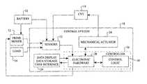
- FIG. 1is a block diagram of a drive system that can implement the control systems and methods disclosed here.
- FIG. 2is a block diagram of one embodiment of a control system that can be used with the drive system of FIG. 1 .
- FIG. 3is a block diagram of a drive control system having an integrated controller.
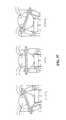
- FIG. 4is a perspective view of a drive control system as implemented in a vehicle.
- FIG. 5is a second perspective view of the drive control system of FIG. 4 .
- FIG. 6is a perspective view of one embodiment of a user interface device that can be used with the control system of FIG. 2 .
- FIG. 7is a schematic block diagram of one embodiment of an integrated transmission and drive motor controller that can be used with the drive system of FIG. 1 .
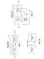
- FIG. 8is a schematic block diagram of one embodiment of a transmission and drive motor controller adapted to cooperate with a stand alone drive motor controller.
- FIG. 8Ais a schematic block diagram of one embodiment of a CVT controller adapted to cooperate with a stand alone drive motor controller.
- FIG. 9is a chart showing a typical saw tooth vehicle acceleration that can be simulated by embodiments of the transmission and/or prime mover controllers disclosed here.
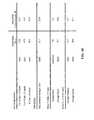
- FIG. 10is a data table showing observed differences and advantages obtained by using the transmission and/or prime mover controllers disclosed here as compared to certain known fixed ratio drive systems.
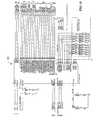
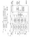
- FIG. 11is a schematic diagram of one embodiment of a transmission and/or prime mover control system according to inventive systems and methods disclosed here.
- FIG. 12is a schematic diagram of a power control module that can be used with the control system of FIG. 11 .
- FIG. 13is a schematic diagram of a universal serial bus interface that can be used with the control system of FIG. 11 .
- FIG. 14is a schematic diagram of a test interface that can be used with the control system of FIG. 11 .
- FIG. 15is a schematic diagram of a controller that can be used with the control system of FIG. 11 .
- FIG. 16is a schematic diagram of a main drive module that can be used with the control system of FIG. 11 .
- FIG. 17is a schematic diagram of a user interface module that can be used with the control system of FIG. 11 .
- FIG. 18is a schematic diagram of a shift actuator control module that can be used with the control system of FIG. 11 .
- FIG. 19is a schematic diagram of a serial peripheral interface that can be used with the control system of FIG. 11 .
- FIG. 20is a schematic diagram of a com interface module that can be used with the control system of FIG. 11 .
- FIG. 21is a schematic diagram of a power monitor module that can be used with the control system of FIG. 11 .
- FIG. 22is a block diagram of a control system that can be used with the drive system of FIG. 1 .
- FIG. 23is a block diagram of one embodiment of yet another control system that can be used with the drive system of FIG. 1 .
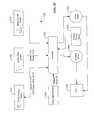
- FIG. 24is a block diagram of one embodiment of another control system that can be used with the drive system of FIG. 1 .
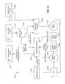
- FIG. 25is a block diagram of one embodiment of yet another control system that can be used with the drive system of FIG. 1 .
- FIG. 25 Ais a block diagram of one embodiment of still another control system that can be used with the drive system of FIG. 1 .
- FIG. 26is a block diagram of one embodiment of a yet another control system that can be used with the drive system of FIG. 1 .
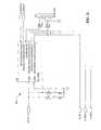
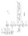
- FIG. 27is a flowchart describing one embodiment of a control process that can be used with the drive system of FIG. 1 .
- FIG. 28is a flowchart of a transmission and/or prime mover control subprocess that can be used with the process of FIG. 27 .
- FIG. 29is a flowchart of a transmission control subprocess that can be used with the subprocess of FIG. 28 .
- FIG. 30is a flowchart of a subprocess for determining a speed ratio of a CVT, which subprocess can be used with the transmission control subprocess of FIG. 29 .
- FIG. 31is a flowchart of a subprocess for controlling a shift actuator of a CVT, which subprocess can be used with the transmission control subprocess of FIG. 29 .
- FIG. 32is a chart representing a speed ratio of a CVT versus vehicle speed lookup table that can be used with the subprocess, of FIG. 30 , for determining a speed ratio of a CVT.
- FIG. 33is a data table used to derive the chart of FIG. 32 .
- FIG. 34is a cross-sectional view of a CVT that can be used with the control systems described here.
- FIG. 35is a cross-sectional view of a shifting mechanism for a CVT that can be used with the control systems and methods described here.
- FIG. 36is a cross-sectional view of a CVT variator mechanism for adjusting the speed ratio of a CVT, which can use the shifting mechanism of FIG. 36 .
- FIG. 37is a schematic diagram that shows certain kinematic relationships of a ball planetary CVT.
- FIG. 38is chart that presents data illustrating the power level delivered to the wheel of an EV when equipped with a CVT and when equipped with a fixed ratio drive.
- FIG. 39is a chart that presents data illustrating the torque versus speed relationships for an EV equipped with a CVT and for an EV equipped with a fixed ratio drive.
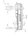
- FIG. 40is a perspective view of an exemplary controller that can be used EV drivetrains disclosed here.
- FIG. 41is an exploded perspective view of certain components of the controller of FIG. 40 .
- FIG. 42is a partial, cross-section showing certain components of the controller of FIG. 40 .
- FIG. 43is an exploded, assembly view of an actuator control circuit board and a drive motor control circuit board that can be configured for use with the controller of FIG. 40 .
- a typical powertrain of an electric vehicleincludes a power source (for example, a battery), an electric drive (for example, a drive motor and a drive motor controller), and a fixed-gear transmission device (for example, sprockets, chain, gearing, etc.).
- a power sourcefor example, a battery
- an electric drivefor example, a drive motor and a drive motor controller
- a fixed-gear transmission devicefor example, sprockets, chain, gearing, etc.
- an EV systemcan be improved by incorporating a continuously variable transmission (CVT) into the EV drivetrain.
- CVTcontinuously variable transmission
- vehicle performancecan be improved because the drivetrain can be optimized at particular operational speeds and load conditions.
- a CVTalso improves the efficiency of an EV.
- the efficiency of the electric motoris a function of operating speed and load, and battery life is a function of current draw.
- a CVT and a suitable controllerallow the drivetrain to operate at speeds of the drive motor, and with selected drive motor current management, such that overall efficiency and range can be improved.
- the CVTis a NuVinci® CVT, which is a compact, high torque-density unit that uses a planetary configuration based on spheres and traction to provide continuously variable speed ratio control.
- a NuVinci® CVT and a suitable control systemcan provide smooth, seamless shifts of the transmission speed ratio across the full range of speed ratios.
- the control systemis able to control component speeds precisely, allowing them to operate substantially at their optimal speed for a given operating condition.
- the control logicalso allows programming for different conditions, allowing the user (or manufacturer) to decide when performance or range is ultimately desired. Certain configurations of the NuVinci® CVT are easily packaged on an EV, and do not significantly affect the cost or the weight of the EV.
- a CVTcan allow the EV to operate in a desired mode, such as a performance mode or an efficiency mode.
- range and efficiencyare less important than outright performance, and the transmission control system optimizes for acceleration, maximum speed of the EV, and hill climbing at speed, for example.
- rangeis the priority, so the control system keeps the drive motor at its most efficient speed and imposes limits on current draw from the battery, for example.
- a control strategyuses data for motor efficiency versus motor speed and motor torque, as well as battery life versus current draw, to improve performance and efficiency of the overall system.
- Analysis modelsindicate that there are benefits of using a CVT in EVs, and the results of the modeling have been confirmed by empirical testing of CVT-equipped EVs that were compared to benchmark stock vehicles (fixed-gear ratio).
- the typical duty cycle of an EVis highly dynamic because it involves numerous stops and starts, uneven terrain, and variable wind resistance.
- a drivetrain with a CVTcan benefit an EV that operates over these dynamic speed and load conditions by allowing the drive motor to operate closer to its peak power or peak efficiency over a broad range of a given duty cycle.
- a propulsion sourcewhen coupled to a CVT a propulsion source is capable of generating more torque and more speed than when coupled with a fixed gear ratio transmission.
- a CVT lower gear ratiocan allow for better launch feel and better hill climb ability, while a CVT higher gear ratio can allow for higher maximum speeds.
- increased acceleration of the EVis possible because the CVT changes the effective inertia seen at the drive motor.
- the CVTis installed in a recreational-type LEV using an in-wheel configuration where the housing of the CVT also forms the spokes and rim of the wheel.
- a drive motoris configured to transfer power to the transmission via a chain and sprocket coupled to the transmission.
- Alternative methods of integrating the CVP to a vehicleinclude mounting the CVP to the chassis or the drive motor, or integrating the wheel, CVP, and drive motor as one unit, for example.
- FIG. 37there is shown the system kinematics of a well-known CVT, where r i is the contact radius of the input contact, and r o is the contact radius at the output contact.
- the transmission speed ratiois determined by the tilt angle of the ball axis, which changes the ratio of r i to r o , and thus the transmission speed ratio. The result is the ability to sweep the transmission through the entire ratio range smoothly.
- the firstis the geometric configuration of the drive, which is based on differential contact radii of a sphere. Contacting a rotating sphere at two different locations provides a “gear ratio” (that is, a transmission speed ratio), which can range from underdrive to overdrive depending on the location of the contact points for input and output speed.
- the spheresare placed in a circular array around a central traction component and contact an input ring and an output ring. Continuously variable transmission speed ratios are possible by tilting the rotational axis of the spheres (that is, varying the contact radii between the spheres and the input and output rings). This configuration allows input and output to be concentric and compact. The result is the ability to sweep the CVT through the entire ratio range smoothly.
- the second feature the NuVinci® CVT exhibitsis a traction fluid.
- a typical traction driveuses a traction fluid that under normal circumstances and pressures provides lubrication for the drive. When the traction fluid undergoes high contact pressures, the fluid undergoes a phase change and becomes a tractive solid. Within a traction patch, molecules of the fluid stack up and form a solid through which shear and torque can be transferred.
- the CVT for an EVuses multiple spheres to transfer torque through multiple traction patches.
- a drive motor and a transmission controllerare configured to optimize the drive-train components of the EV.
- the hardwarecan be provided as an add-on controller that works in conjunction with the existing motor controller of the EV, or as a stand-alone integrated controller.
- correct CVT speed ratiocan be determined from a speed sensor and a throttle position (intercepted between the throttle and the drive motor controller).
- control of the drive motor and of the CVTcan be joined more intimately, thereby increasing efficiency, simplicity, and reducing cost.
- the control systemcan react to driving conditions and is configured to keep the drive motor in an optimal range for a given operating condition.
- the term “operating condition”refers to a vehicle operating parameter, environmental state, and/or user selections, commands, or inputs. Additionally, the control system can take into account battery state of charge and duty cycle efficiency to help manage power consumption.
- the NuVinci® CVTis installed in an EV.
- the CVTis integrated into the rear wheel of the EV, and the CVT speed ratio is controlled automatically via a shift actuator and an electronic control system.
- the EV application of the NuVinci® CVTuses a shift actuator and a suitable control system to allow continuous and optimized shifting.
- the EVis equipped with an electronic controller that monitors system operating parameters (for example, battery current, wheel speed, shift position, etc.) to control the CVT and the drive motor in closed loop control.
- system operating parametersfor example, battery current, wheel speed, shift position, etc.
- inventive embodiments described herecan be used with various types of CVTs, including belt-pulley CVTs, toroidal CVTs, cone-based CVTs, Milner CVT, hydrostatic CVTs, and the like.
- control systemcan optimize the drive motor speed, battery current, and transmission speed ratio based on, for example, drive motor and CVT efficiency maps. In one example, the system seeks to keep relatively constant the speed of the drive motor and/or to limit the maximum current draw from the battery.
- a shift actuatoris configured to shift the speed ratio of the transmission.
- the transmission control systemcan be integrated with the motor controller (single control unit per vehicle), or can operate in conjunction with a drive motor controller already provided with the EV.
- the transmission controllercan be configured to read drive motor current draw, drive motor speed, wheel speed, and/or battery voltage to determine the best CVT speed ratio for a given operating condition. This allows the drive components to operate at optimal speeds for the given operating conditions (including taking into account the selected mode of operation).
- Currie IZIP 1000 scooter(a direct-drive EV) was used for simulation and analysis.
- Vehicle dynamics equationsillustrate the possible performance advantages of a CVT added to this direct-drive EV.
- M vmass of the vehicle and rider
- a vacceleration of the vehicle and rider
- F ttractive force at the drive wheel
- F fforce due to total road loads
- F wforce due to aerodynamic drag.
- F t( T m - I eg m ⁇ ⁇ m ) ⁇ i o ⁇ i cvp ⁇ ⁇ cvp r d ( 2 )
- F fM v ⁇ g ⁇ ( f r + slope ) ( 3 )
- F w1 2 ⁇ ⁇ ⁇ ⁇ C d ⁇ A f ⁇ v 2 ( 4 )
- T mtorque output of the drive motor
- I eg mequivalent reflected inertia at the drive motor
- ⁇ mangular acceleration of the drive motor
- i ogear ratio of the drive motor to the CVP (motor speed/CVP input speed)
- i cvpgear ratio of CVP (CVP input speed/CVP output speed);
- ⁇ cvpefficiency of CVP
- r deffective radius of the tire
- gacceleration due to gravity
- f rrolling resistance coefficient
- slopeelevation divided by distance
- ⁇density of air
- C daerodynamic drag coefficient
- a ffrontal area of vehicle and rider
- vvelocity of vehicle and rider.
- I mrotational inertia of the motor
- I wrotational inertia of the wheel
- Equation 1For vehicle launch, initial speed and aerodynamic drag are zero. At this instant, the acceleration of the vehicle is determined from Equations 1 through 4 and is:
- a v( T m - I eq m ⁇ ⁇ ) ⁇ i o ⁇ i cvp ⁇ ⁇ cvp M v ⁇ r d - gf r ( 6 )
- FIG. 38shows that for a representative drive motor curve, the CVT allows the drive motor to reach the peak power condition at a lower speed of the EV than with a fixed ratio configuration.
- the CVTcan also have a significant effect on reflected inertia at the motor shaft, as defined in equation 5.
- a higher gear ratioreduces the rotational inertia reflected at the drive motor, and thus increases acceleration for a given torque.
- the control systemcan use the CVT to manage acceleration at all portions of the drive cycle.
- a reasonable metric for hill climb capabilitycan be defined as the max num steady state speed that can be achieved on a given slope. Because this is a steady state metric, the acceleration component of equation 1 is zero and we can determine the speed for a given slope by combining equations 1 through 4 and solving for steady state velocity:
- a CVT equipped scootercan theoretically obtain at least a 69% increase in steady state velocity up a given slope. It should be noted that this is the case because in the stock scooter the speed of the drive motor drops below its base speed, where the drive motor delivers less power. It can also be shown that the maximum slope the EV and rider can climb increases by at least 45% with a CVT.
- FIG. 39shows that in underdrive the CVT increases the torque delivered to ground and increases the hill climb capability of the EV.
- Maximum speedis defined as the maximum speed a vehicle and rider can reach at steady state, with no grade. Similar to the hill climb, acceleration is zero at this condition and there is no dependence on system inertia.
- Two scenarioscan define the maximum possible speed for an electric vehicle. If the drive motor can spin freely to its maximum speed, the vehicle is said to be motor speed-limited. If the drive motor cannot overcome the total road load and aerodynamic forces before reaching its top speed, the vehicle is said to be power-limited.
- the maximum speed of the EVcan be increased by adding a CVT, as shown in the overdrive region of FIG. 39 .
- the vehiclecan be geared such that, at the maximum speed of the EV, the tractive force at the wheel is completely opposed by the road loads and aerodynamic drag. This is also governed by equation 7.
- the Currie IZIP 1000 scooteris motor speed-limited, and therefore it benefits from the addition of the CVT.
- equation 7with representative values for the Currie scooter, it can be shown that the maximum speed of the EV can be increased by up to 75%.
- the control systempreferably takes into account battery performance, as well as drive motor and transmission efficiency. Additionally, the control system is preferably configured to take a systems approach to controlling all the components to conditions that optimize overall system efficiency.
- the operating range of an EVis dependent on the drive cycle (for example, frequency of stops and starts and hill climb and descent).
- a drive cyclewas used that included no stops, four substantial elevation changes, and speeds ranging from 16-kph to 24-kph on the stock Currie IZIP 1000 scooter.
- a dynamic simulationwas created to model the performance of a 1000 W scooter over the chosen drive cycle.
- the simulationincluded the following features: (a) dynamic permanent magnet DC motor model (including measured efficiency data), (b) dynamic CVP model (including measured efficiency data), (c) total road load and aerodynamic drag model, (d) battery model where voltage drops as a function of current draw, and (e) current limiter that limits input power to the drive motor.
- a control processsimulated control of the transmission speed ratio of the CVT to shift the CVT when an efficiency improvement could be achieved. Otherwise, the control process kept the CVT at the transmission speed ratio of peak efficiency.
- the simulationshowed that for the given duty cycle, the CVT-equipped scooter approximately matched the range performance of the stock scooter while still providing improvements in hill climb, acceleration, and maximum speed of the EV.
- test EVwas the 2006 model Currie IZIP 1000 scooter.
- a NuVinci® CVTwas integrated into a rear wheel design, which is compatible with the frame of the stock scooter.
- Testswere conducted with a data acquisition system fixed to the vehicle that included a data logger, supply battery, and various sensors and wiring. Four tests were performed, including standing start acceleration, maximum speed, hill climb ability and range. For acceleration, hill climb, and range tests, the system control software limited the maximum speed of the CVT-equipped scooter to match approximately the maximum speed of the stock scooter.
- the acceleration testwas conducted from a standing start on flat asphalt and used a predetermined start line and an infrared photogate for the finish line at a distance of 0.2-km.
- Speed datawas used to obtain acceleration times from 0-kph to 16-kph and 0-kph to 19-kph, and the time to complete the distance.
- the maximum speed of the scooterwas measured as an independent test on flat asphalt with the speed limit removed.
- the systemwas manually set to its maximum, possible sustained vehicle speed, and speed data was recorded.
- the hill climb benchmarkwas performed on a predetermined hill with a subtly increasing grade over a fixed distance of 0.75-km.
- the range testinvolved driving the vehicle continually over a 5.15-km loop until the maximum, sustained vehicle speed dropped below a predetermined level.
- the courseincluded a variety of grades and two stops and starts.
- drive cycle characteristicssuch as GPS data, elevation, and hill grade
- the results of the benchmark testsindicate significant increases in performance and hill climb capability.
- the 0-kph to 16-kph and 0-kph to 19-kph timesrepresent 25% and 24% increases, respectively, with the use of the CVT and the control system. Additionally, the time to complete the hill climb test was almost halved, and there was an 85% increase in average speed.
- the CVT-equipped vehicleachieved a maximum speed of 34-kph, which represents a 61% increase over the maximum speed of the stock vehicle. This indicates that the maximum speed of the stock vehicle is not power-limited, but rather, is motor speed-limited.
- the maximum speed limit of the CVT-equipped EVwas set slightly higher than with the stock EV, yielding higher aerodynamic losses.
- the drive motor controllerallowed the battery to deliver slightly higher current with the CVT-equipped EV. It is notable that the CVT and the control system provided substantial performance improvements with negligible impact on range. The benefits realized are, in part, a result of controlling the drive motor and the transmission as a system.
- the stock scootershowed reasonable consistency in performance data, but failed to climb hills with a 10% without overloading the drive motor controller. With an adult rider, the advertised maximum speed of the stock scooter could not be achieved.
- the controllercan be configured to facilitate different modes of operation. In some cases, it is preferable to have an economy mode where the EV is used for commuting or a performance mode where the EV is used for recreation. Although not as efficient, manual shifting of the transmission can provide a unique and fun aspect to rider experience.
- the desired controller modecan be selected through an external user interface, throttle position, or can be set by the control system automatically by analyzing driving parameters, inputs, and history.
- the control systemcan be configured to command the CVT to allow the drive motor to operate at its most efficient speed for generating energy to supply back to the battery system, when regeneration is required during braking or extended descents.
- drivetrains for EVsthat incorporate one or more configurations of CVTs, drive motor, and suitable controllers and processes for optimizing EV performance, range, etc., under various operating conditions and/or desired operating modes.
- drivetrainand “powertrain” are used interchangeably; it should be understood that in some embodiments a drivetrain includes references to a power source, such as a battery.
- a drive system 10includes a prime mover 12 coupled to a continuously variable transmission (CVT) 14 , which is coupled to a load 16 .
- a control system 18is adapted to receive information from the prime mover 12 , CVT 14 , and/or load 16 .
- the control system 18can also be adapted to provide commands to or actuate the prime mover 12 and/or the CVT 14 .
- the prime mover 12can be any source of power, such as an electric motor, internal combustion engine, wind turbine, a combination thereof, etc.
- the electric motorcan be, for example, a brushed DC motor, a brushless DC motor, a permanent magnet motor, or any other type of electric motor.
- the load 16can be a tractive load, which can include the weight of vehicle and/or an operator and/or cargo and passengers.
- the CVTcan be a ball planetary CVT, a toroidal CVT, or a belt-and-pulley CVT, for example.
- a drive system 10includes a NuVinci® continuously variable planetary, and a drive mechanism between the prime mover and the CVT.
- the drive mechanismcan be, for example, a chain and sprocket drive, a direct gear drive, or any other type of power transmission gearing.
- the control system 18includes sensors, actuators, and control hardware, firmware, and logic as described further below.
- the system, or subassemblies thereof, shown in FIG. 1can be adapted for use in any ground, air, or water transportation machine, industrial or agricultural equipment, aerospace vehicles and equipment, and household machines, to name a few applications.
- FIG. 2illustrates one embodiment of a control system 18 that includes a controller 20 in communication with sensors 22 , a data display and user interface 24 , a mechanical actuator 26 , and the prime mover 12 .
- the controller 20includes electronic hardware 28 in communication with control logic 30 .
- the sensors 22are adapted to sense conditions of the prime mover 12 , load 16 , and a battery 32 , which can be configured to provide power to the prime mover 12 .
- the battery 32can be, for example, a 36V battery.
- a controller 302can control the CVT 14 and the prime mover 12 to maximize the performance and efficiency of a vehicle.
- This embodimentcan be referred to as an integrated control in that most or all of the control components and functionality used to control the CVT 14 and the prime mover 12 can be integrated in a single controller 302 , which in some embodiments includes a single electronic board.
- the controller 302can be adapted to receive a throttle input (which can be a voltage source).
- a control system 300can include an actuator motor 304 to actuate a shift (that is, an adjustment) of the speed ratio of the CVT 14 .
- the CVT 14can be coupled to the drive wheel assembly of a vehicle, for example.
- the systemincludes sensors. These can include a wheel speed sensor 306 for sensing wheel speed and/or a motor speed sensor 308 for sensing the speed of the drive motor.
- the sensors 306 , 308can be any type of speed sensor, for example an active magnetic sensor, passive magnetic sensor, or encoder of any type.
- the speed of the drive motor 12can be sensed directly in a controller 340 by measuring the frequency of electric current supplied to the drive motor.
- an actuator position sensor 310can be, for example, an encoder or potentiometer.
- the actuator positioncan be derived from the measured speed ratio of the CVT 14 .
- the speed ratio of the CVT 14can be calculated from the wheel speed, speed of the drive motor 12 , and any gear ratios in the system.
- the system 300can additionally include a throttle position sensor 312 , a battery fuse switch and/or sensor 314 , and a brake cut-off switch and/or sensor 316 , any of which can be configured to provide signals to the controller 302 .
- FIGS. 4 and 5show different views of one embodiment of a drive system 400 .
- a frame 402 of a vehicle(a scooter, electric bicycle, or motorcycle, for example) supports a drive motor 404 that is coupled to a CVT 406 via a pinion 408 , a chain 410 , and a sprocket 412 .
- the CVT 406is integrated in the rear wheel hub of the vehicle and it drives a rim 414 via spoke 416 .
- a shift actuator 418is coupled to the CVT 406 .
- the shift actuator 418can include a shift actuator motor and suitable gearing (such as reduction gears, for example).
- the control system 18includes a user interface device 502 as shown in FIG. 6 .
- the interface device 502can display at least some of the operating parameters of the system 10 , for example, battery voltage, speed of the drive motor 12 , speed of the vehicle 506 , throttle position, speed ratio of the CVT 14 , or mileage. Mileage can be displayed in terms of Watt-hrs/mile or some other units.
- the interface device 502can be equipped with input buttons 504 to allow selection of different modes of operation while stopped or driving.
- the interface device 502can be integral with the vehicle 506 . Alternatively, the interface device 502 can be removable, with attachment hardware that allows easy removal of the interface device 502 .
- the interface device 502can be configured to record data of any signal generated or derived from the controller 340 . Data can be recorded at periodic frequency, for example, a reading of all measured or derived signals every 50 ms.
- a machine equipped with the control system 300offers advantages over control systems with either a fixed ratio chain drive or a manually controlled CVT.
- the controller 302manages the speed and current of a drive motor 12 , the current draw from a battery, and the speed ratio of the CVT 14 to optimize the efficiency, acceleration, hill climb capability, and ride feel of a given vehicle, while minimizing noise.
- the controller 302can be assembled and operated in several configurations.
- the controller 302can include a drive motor controller 302 A, for controlling the drive motor 12 , as well as a CVT controller 302 B, for controlling the CVT 14 , all integrated on one board, as shown in FIG. 7 .
- the controller 302can be operated to control only the CVT 14 and to cooperate with an existing drive motor controller 320 installed on a given vehicle.
- the drive motor controller 302 A in the fully integrated configuration of Figure Gis disabled and the CVT controller 302 B cooperates with the separate motor controller 320 , as shown in FIG. 8 .
- the CVT controller 302 Bcan sense and communicate different operating parameters generated by the separate motor controller 320 .
- the controller 302can control the drivetrain based on several inputs, such as speed of the drive motor 12 , vehicle speed, current of the drive motor 12 , or throttle signal.
- the control system 18can have several modes of operation.
- an acceleration mode(“drag race”)
- vehicle accelerationis maximized by quickly setting the CVT 14 in a full underdrive configuration as the vehicle launches, thus allowing the drive motor 12 to accelerate to its highest power condition and providing mechanical torque advantage to the drive motor 12 .
- the control system 18shifts the CVT 14 according to the speed of the vehicle such that the speed of the drive motor 12 is held at the peak power condition of the drive motor 12 according to the torque, current draw, and speed of the drive motor 12 .
- the control system 18in acceleration mode the control system 18 can control the electrical current between the battery 32 and the drive motor 12 in several ways.
- the control system 18can limit the maximum allowable current or the length of time above a certain current level, for example 65 Amps (A).
- a range mode(“economy”), the operating range of the vehicle on a single battery charge is maximized by controlling the acceleration and top speed of the vehicle to minimize power usage during driving.
- the controller 20controls the speed ratio of the CVT 14 to allow the drive motor 12 to operate at its most efficient speed through all operating conditions in a given driving cycle. Further, the controller 20 can minimize the maximum current draw from the battery and the length of time operating above a certain current condition.
- the control system 18can control the CVT 14 to simulate the operation of a multispeed transmission.
- the controller 20controls the speed ratio of the CVT 14 to a constant underdrive value, for example 2:1, and allows the speed of the drive motor 12 to accelerate through the operating range of the drive motor 12 , for example from 500 rpm to 3500 rpm, as the vehicle accelerates.
- the controller 20then quickly shifts the CVT 14 , for example in less than 500 ms, to a higher speed ratio, for example 1.5:1 while simultaneously allowing the speed of the drive motor 12 to quickly drop back to a low speed, for example 500 rpm.
- controller 20repeats the same acceleration of the drive motor 12 and continues vehicle acceleration while holding constant the speed ratio of the CVT 14 .
- the controller 20can repeat this procedure for any number of speed ratios of the CVT 14 , for example 5 or 6 settings.
- the mode of operation described by the fixed ratio simulation modeis similar to the “saw tooth” acceleration shown in FIG. 9 .
- a hill climb modethe performance of the vehicle while climbing a hill is maximized.
- the control system 18controls the CVT 14 to a low speed ratio such that the drive motor 12 has a mechanical advantage as compared with a fixed ratio vehicle driveline. Additionally, the controller 20 can optimize the current draw to the drive motor 12 to manage the power delivered to the ground to optimize the ability of the vehicle to climb the hill.
- the control system 18allows an operator to control manually the CVT 14 .
- the usercan use buttons, for example, on the user interface device 502 to increase or decrease the speed ratio of the CVT 14 .
- the operatorcan additionally select the mode (for example, economy, hill climb, etc.) using the user interface device 502 .
- the top speed of the vehicle and the drive motor 12can be controlled to any desired value within the full operating ratio range of the CVT 14 and the drive motor 12 .
- the operating modes described abovecan provide performance improvements of a vehicle equipped with the control system 18 and a CVT 14 versus a conventional fixed ratio drive system.
- FIG. 10presents an example of observed performance differences and/or improvements.
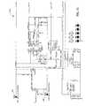
- FIG. 11shows a schematic diagram of one embodiment of a control system 600 .
- the control system 600can include several subsystems, such as a power control module 610 , a USB Interface 620 , a test interface 630 , a controller 640 , a main Drive 650 , a user interface 660 , an actuator control module 670 , SPI 680 , a com interface 690 , and a power monitor 695 .
- FIG. 12shows one embodiment of the power control module 610 .
- the power control module 610receives power from the battery 32 and incorporates voltage regulators and signal conditioners to regulate the output voltage into several distinct steady levels, possibly including for example 3 volt (V), 5V, 15V, 36V.
- the power control module 610can provide an analog diagnostic signal of the battery voltage to the controller 640 .
- the power control module 610includes two connections points TERM 5 101 and TERM 6 102 , which represent the positive and negative lines coming from the 36V battery.
- the power control module 10has six built-in connection points that enable the power control module 610 to communicate with other subsystems on the control system 600 .
- a connection VCCP 3 _ 3 Vsupplies a steady 3.3V supply rail to the rest of the system.
- a connection VCCP 5 Vsupplies a 5V
- VCCP 15 Vsupplies 15V
- VCCP 36 VOis the battery voltage supply rail to the entire system.
- BAT_VFBis an analog voltage signal that is sent to the controller 640 to monitor the voltage of the battery 32 during operation.
- FIG. 13shows a USB interface 620 , which includes a Universal Serial Bus (USB) interface that allows a user to connect external programming or data acquisition hardware, for example a personal computer, to the control system 600 and specifically interface with hardware on the controller 640 .
- the USB interface 620includes six connection points.
- the USB interface 620is powered by VCCP 5 V and VCCP 3 _ 3 V. The remaining four connections are common to a typical USB interface.
- the lines marked DDn and DDpare differential data pairs that enable the controller 640 to recognize the device connected to the USB port.
- the line marked VBis the 5V bus detector.
- the PC lineis the pull up control.
- FIG. 14shows one embodiment of the test interface 630 .
- the test interface 630allows developers to access the hardware on the control system 600 and, in particular, to access components built into the controller 640 .
- the test interface 630has specific test points built into the board to measure voltage and confirm operation of various components.
- the test interface 630functions as the port through which firmware is downloaded to the controller 640 .
- the test interface 630can contain a series of headers or connector pins so that a developer can connect external programming hardware, for example a computer.
- connection points in the test interface 630there are twelve connection points in the test interface 630 .
- the test interfacereceives signals from the VCCP 5 V and the VCCP 3 _ 3 V to power the subsystem for its communication with the controller 40 .
- the test interface 30can be adapted to communicate with the controller 640 through connections that are organized into industry standard functional groups.
- the lines labeled SEL, TDI, TMS, TCK, TDO, and NRSTare part of an IEEE standard 1149.1 for Standard Test Access Port and Boundary-Scan Architecture for test access ports used for testing printed circuit boards. This standard is often referred to as JTAG, an acronym for Joint Test Action Group.
- the lines labeled TST and ERASEare used to put the controller 640 into different modes and erase the flash memory, respectively.
- the lines labeled DTXD and DRXDare part of a known connection type called a universal asynchronous receiver/transmitter (UART), which is computer hardware that translates data between parallel and serial interfaces. These connections are used for serial data telecommunications, a UART converts bytes of data to and from asynchronous start-stop bit streams represented as binary electrical impulses.
- UARTuniversal asynchronous receiver/transmitter
- FIG. 15shows one embodiment of the controller 640 , which contains a microcontroller, firmware, random access memory, flash memory, and other hardware peripherals to allow communication between the controller 640 and other subsystems of the control system 600 .
- the controller 640holds a majority of the control processes for the controller 640 , which is used to manage operations of the control system 600 .
- Certain subsystemshave several connections to communicate with the controller 640 . These connections are described in correlation with the subsystems disclosed. In addition to those connections, there can be additional connection points or headers included in the board of the controller 640 for miscellaneous use. For example, referencing FIG. 11 , there are three pins TP 4 , TP 1 , and TP 2 .
- FIG. 16illustrates one embodiment of the main drive 650 .
- the main drive 650can be adapted to control the drive motor 12 .
- There are several power connections to the main drive 650which utilizes power from the VCCP 36 V line that is connected directly to TERM 4 on the drive motor 12 .
- the DRV_PWM linerepresents a pulse width modulated current signal that the controller 640 generates to control the current that passes to the drive motor 12 and thus control the torque the drive motor 12 applies to the system 10 .
- the BRAKE linedelivers a signal from the brake detection switch that can be installed on the vehicle under the brake lever, for example, to detect when the operator engages the brake. If the brake is engaged, the BRAKE signal commands the main drive 650 to turn off to prevent damage to any component in the drivetrain or the control system 600 .
- VCCP 5 V, VCCP 3 _ 3 V, VCCP 15 Vare lines for 5V, 3.3V and 15V supply voltages respectively.
- the DRV_IFB lineis the motor current detection signal from the main drive 650 .
- DRV_IFBis an analog signal read by the controller 640 .
- the firmware loaded on the controller 640uses the DRV_IFB signal as feed back to control the drive motor and protect against over-current conditions that may arise during normal operation.
- the lines DRV_POS_A and DRV_POS_Bcan be used to detect the direction of the drive motor 12 .
- DRV_POS_Acan be used to measure speed of the drive motor and DRV_POS_B can be used to detect operating modes from the controller 640 .
- FIG. 17shows one embodiment of a user interface module 660 .
- the user interface module 660represents the communication with hardware the operator uses to control the system 600 .
- the user interface 660includes the Brake, Throttle and Battery Voltage feedback.
- the user interface 660can receive signals from VCCP 36 V and VCCP 5 V.
- FIG. 18illustrates one embodiment of a shift actuator control 670 .
- the shift actuator control 670can be adapted to control the actuator motor 304 (for example, see FIG. 3 ) that adjusts the speed ratio of the CVT 14 .
- the shift actuator control 670is the physical interface to the actuator motor 304 and receives power from all of the regulated voltage lines.
- the shift actuator control 670receives signals via ACT_DIR 1 and ACT_DIR 0 from the controller 640 that define the direction of rotation of the actuator motor 304 .
- the shift actuator control 670can receive a PWM signal from the controller 640 via ACT PWM that defines the electrical power and current level going to the actuator motor 304 .
- ACT IFBis a measurement signal indicating to the controller 640 the current amperage to the actuator motor 304 .
- the controller 640can include logic to limit and manage the current driving the actuator motor 304 .
- the shift actuator control 670can receive signals from an actuator position sensor 310 , for example, and quadrature encoder or potentiometer and sends the signals to the controller 640 via ACT_POS_A and ACT_POS_B.
- FIG. 19shows the serial peripheral interface (SPI) 680 .
- the SPI 680can be a standard synchronous serial data link that operates in full duplex mode. Devices communicate in master/slave mode where the master device initiates the data frame. Multiple slave devices are allowed with individual slave select (chip select) lines.
- FIG. 20illustrates one embodiment of the com interface 690 , which is the physical interface for an interface module 502 .
- the connectors shown in FIG. 11are known transmitter/receiver pairs for communication with the interface module 502 .
- FIG. 21shows one embodiment of the power monitor 695 , which monitors the operation of the system 600 and in the event of a loss of control or unexpected occurrence shuts down the system 600 by short circuiting the battery lines and blowing the fuse of the system 600 .
- the shutdown commandis sent via D_RWAY and RUN_AWAY.
- the power monitor 695can include a second microcontroller that makes decisions based on the system operation.
- the power monitor 695monitors actuator current, A_IFB, and will disable power to the actuator motor via A_SHDN if necessary.
- the power monitor 695monitors the PWM signal to the drive motor via D PWM.
- the power monitor 695can receive a signal VCCP 3 _ 3 V.
- a control system 2200can include a controller 2202 adapted to receive inputs such as battery status, throttle position, throttle rate, vehicle speed, current in a drive motor 2204 , speed of the drive motor 2204 , a mode selection, and a position of an actuator 2206 that adjusts a speed ratio of a CVT 2208 . Based on at least some of these inputs, the controller 2202 commands a motion of the actuator 2206 .
- the controller 2202can be additionally adapted to provide status or other indicators to, for example, a user interface and/or to a data storage device.
- a control system 2300can include a controller 2302 coupled to a drive motor 2304 and to an actuator motor 2306 .
- the drive motor 2304couples to a CVT 2308 , which couples to the actuator motor 2306 .
- the controller 2302can be adapted to receive signals from an actuator position sensor 2310 and/or a wheel speed sensor 2312 .
- the controller 2302can be adapted to receive signals from a throttle position sensor 2314 , a battery fuse switch 2316 , and/or a brake cut-off switch 2318 . Signals from the battery can include voltage and/or current signals indicating the status of the battery.
- a control system 2400can include a transmission controller 2402 coupled to a shift actuator motor 2404 .
- the shift actuator motorcouples to a CVT 2408 .
- the transmission controller 2402can provide commands and/or power to the shift actuator motor 2404 .
- a shift actuator position sensor 2406can be coupled to the shift actuator motor 2404 or to a component of the CVT 2408 .
- a wheel speed sensor 2410which can be coupled to the CVT 2408 , provides signals to the controller 2402 .
- the transmission controller 2402receives signals from a throttle position sensor 2412 and/or a battery status sensor 2414 , which couples to a battery or battery fuse switch 2416 .
- the transmission controller 2402cooperates with a drive motor controller 2418 that is coupled to a drive motor 2420 .
- the CVT 2408can be coupled to the drive motor 2420 .
- a motor speed sensor 2422which can be coupled to the drive motor 2420 , sends signals to the transmission controller 2402 .
- a brake cut-off switch 2424can be adapted to provide signals to the drive motor 2418 .
- the transmission controller 2402provides a throttle signal to the drive motor controller 2418 .
- control system 2400can be configured such that a transmission controller 2402 is used for controlling the speed ratio of a CVT 2408 , a drive motor controller 2418 is used for controlling a drive motor 2420 , and the controllers 2402 , 2418 are configured to cooperate in controlling a drive system, such as drive system 10 of FIG. 1 .
- a control process and drive system 2500can include sensors 2502 that provide signals to a controller 2504 , which is adapted to control a shift actuator of a transmission and a drive motor.
- energyis supplied to the system 2500 from battery 2506 , and the energy is ultimately converted to a mechanical actuation of a shifter mechanism of the transmission, and powering a wheel of a vehicle via the drive motor, to provide an appropriate or desired vehicle speed.
- a throttle inputis provided to a throttle position sensor 2508 , a drive motor speed sensor 2510 , and a motor power sensor 2512 .
- Vehicle inputscan be received from the motor power sensor 2512 , vehicle speed sensor 2514 , and a speed ratio sensor 2516 of the transmission.
- Signals from the batterycan be provided to the vehicle speed sensor 2514 and to the drive motor speed sensor 2510 .
- the controller 2504can be configured to determine at a module 2518 an optimum drive motor speed (in rpm, for example) and/or at a module 2520 an optimum motor power based on one or more signals provided by the throttle position sensor 2508 , drive motor speed sensor 2510 , and/or the motor power sensor 2512 .
- the controller 2504can be configured to determine at a module 2522 an optimum transmission speed ratio based on at least some of the signals provided by the throttle position sensor 2508 , the speed ratio sensor 2516 , the vehicle speed sensor 2514 , and/or the motor power sensor 2512 .
- the module 2522can also use results from the modules 2518 and 2520 to determine the optimum speed ratio for the transmission.
- the controller 2504includes a module 2524 for determining battery use based on signals received from the motor power sensor 2512 and/or a battery power sensor 2526 .
- the controller 2504includes a drive command module 2528 that receives signals from the optimum motor speed module 2518 and the battery use module 2524 .
- the drive command module 2528governs the transfer of power from the drive motor 12 to the wheel, for example, of a vehicle.
- the drive command module 2528can also be configured to provide a feedback signal to the motor speed sensor 2510 .
- the controller 2504can also include a command shift actuator module 2530 adapted to govern the actuation of a shifting mechanism of a transmission based, at least in part, on results produced by the optimum speed ratio module 2522 .
- a drive and control system 2550includes a CVT actuator and controller 2552 , which is adapted to receive power from a source such as a battery 2554 .
- the actuator and controller 2552can establish an appropriate vehicle speed 2558 based on throttle input 2556 and vehicle inputs 2560 .
- a drive and transmission control system 2600can include a microprocessor 2602 , such as an Atmel ARM7 chip, that is adapted to cooperate with a number of software modules or processes.
- An application programmer interface 2603is in communication with a pulse width modulation module 2604 , which cooperates with a motor control module 2606 .
- a drive motor control module 2608is in communication with the motor control module 2606 and a drive system control module 2610 .
- the motor control module 2606communicates with a position control module 2612 that is in communication with a transmission control module 2614 .
- a main control module 2616is in communication with the drive system control module 2610 , a display output module 2618 , a throttle position module 2620 , a battery fuel gauge module 2622 , and/or a wheel speed module 2624 .
- the process 2700starts at a state 2702 .
- the process 2700moves to a state 2704 , wherein an initialization routine runs a number of processes.
- One processincludes loading system parameters and defaults such as maximum vehicle speed, transmission shift limits, wheel pulse count, wheel size, etc.
- the process 2700then performs various subprocesses.
- the subprocessesincludes an analog-to-digital converter subprocess 2706 , a memory read/write subprocess 2708 , a display IO subprocess 2710 , a test subprocess 2712 , a motor control and throttle subprocess 2714 , and a road speed calculation subprocess 2716 .
- the motor control and throttle subprocess 2714can be configured as a loop that repeats every 5-milliseconds (200 Hz refresh), for example.
- the motor control and throttle subprocess 1014includes a drive control module 2802 and a transmission control module 2804 .
- the drive control module 2802in some embodiments, can be any suitable pulse width modulation motor control scheme.
- the transmission control module 2804includes a position control servo feedback loop.
- the motor control and throttle subprocesscan provide drive motor control and actuator motor position control.
- the motor control and throttle subprocess 2714starts at a state 2800 .
- the process 2714then substantially simultaneously executes the drive motor control module 2808 and the transmission control module 2804 .
- the subprocess 2714determines whether the subprocess 2714 should continue to be executed in its loop. If the decision is to continue, the subprocess 2714 resumes execution of the modules 2802 , 2804 . If the decision is not to continue, the subprocess ends at a state 2808 . In some instance, at the decision state 2806 it is determined not to continue the subprocess 2714 because, for example, an off signal or a brake signal has been issued by the system.
- the drive control module 2802handles the vehicle speed demand and modulates the output of a drive motor.
- the drive control module 2802can also incorporate a soft-start routine to minimize abrupt shocks on a vehicle during high speed demand (that is, fast throttle ON).
- the drive control module 2802accomplishes a soft start by regulating the maximum current that the drive motor can pull and by delaying the throttle signal value, eliminating an instant-on effect.
- the initialization of the transmission control module 2804includes an actuator homing routine to position the transmission at a desired state (for example, the tilt angle of the traction rollers, or power adjusters, is put in an underdrive configuration) to begin a drive cycle.
- the transmission control module 2804on startup drives the shift actuator motor towards underdrive, while reading the position of a shift rod via counts from an encoder on a shaft of the actuator motor.
- an actuator control process 3104stops driving the actuator motor and reads the initial shift position parameter from a shifter subprocess 2902 .
- the actuator control process 3104initially sets the transmission speed ratio to just above full underdrive (for example, 17 degrees gamma into underdrive; wherein, the full underdrive range goes to 18 degrees gamma into underdrive). In one embodiment, the actuator control process 3104 uses encoder counts as an indication of position. After actuator homing, the actuator control process 3104 continues with further operations.
- the transmission control process 2804which begins at a starting state 2900 , determines a required transmission speed ratio (that is, the tilt angle of the traction planets) from a shifter process 2902 that handles the current state of inputs and from a lookup table with prescribed output values of speed ratio of the transmission. The transmission control process 2804 then passes the output set point to the actuator process 2904 , which applies power, via an actuator motor drive module 2906 , to the actuator motor until the set point is reached.
- a required transmission speed ratiothat is, the tilt angle of the traction planets
- the transmission control process 2804receives a set of inputs to describe a state of the vehicle. In one embodiment, these inputs include vehicle speed, drive motor current, and other parameters that describe the state of the vehicle.
- the mode of the controlleris also determined. The mode can be selected manually via a toggle switch or a button. In some embodiments, the mode can be a performance (sport) mode or an economy mode. Yet in other embodiments, the mode can be a simulated 4-speed transmission “sawtooth” mode.
- the controllercan store mode tables in a memory.
- a mode tableis a set of data that includes input parameters (for example, vehicle speed, motor current, etc.) as well as a desirable speed ratio of the transmission as the output parameter. Input values can be used to reference a table and produce an output value. The output value is then passed over to the actuator process 2904 .
- the actuator process 2904can be a proportional control feedback loop using the set point for the speed ratio of the transmission as an input, with the actuator shaft encoder as a feedback signal.
- the actuator motor drive module 2906can include a bi-directional (reversing) routine 2908 , a motor drive routine 2910 , and a suitable pulse width modulation (PWM) routine 2912 .
- PWMpulse width modulation
- FIG. 30depicts one embodiment of a shifter process 2902 .
- the shifter process 2902starts at state 3000 .
- Vehicle speed 3002 , drive motor current 3004 , and/or other parameters 3006are received in a monitor vehicle status module 3008 .
- the shifter process 2902then moves to a mode select state 3010 , wherein a shift mode input 3012 can be received.
- the shifter process 2902then proceeds to a decision state 3014 , wherein the shifter process 2902 determines which shift mode to use. If the shift mode selected is the sport mode, at a state 3016 the shifter process 2902 takes as input the sport mode lookup tables 3018 .
- the shifter process 2902takes as input the economy mode lookup tables 3022 . If the shift mode selected is another mode, at a state 3024 the shifter process 2902 takes as input the appropriate lookup tables 3026 for the selected mode.
- the shifter process 2902determines an optimal speed ratio for the CVT at a state 3028 .
- determining the optimal speed ratio for the CVTincludes determining a position for a shift rod of the CVT.
- determining the optimum speed ratio for the CVTincludes determining a number of encoder counts for actuating a shifter mechanism of the CVT, which shifter mechanism can be a shift rod.
- an embodiment of the actuator process 2904can start at a state 3100 and proceed to execute an actuator control process 3104 .
- the actuator process 2904then executes an actuator hardware and drive module 3106 .
- the actuator process 2904can then end, if an actual CVT position 3108 is substantially the same as the optimum CVT position determined by the shifter process 2902 .
- a lookup table that can be used by the shifter process 2902can be exemplified by each of the curves graphed on the chart shown.
- a speed ratio of the transmissionis selected (which is equivalently to selecting a position of a shifting mechanism of the transmission, such a position of a shift rod; the position can be expressed in terms of encoder counts).
- a curve 3202represents a lookup table for a “drag race” or fast acceleration mode.
- a curve 3204represents a lookup table for an economy (“econ”) mode.
- a curve 3206represents a lookup table for a fixed ratio simulation (or “stepped”) mode.
- a curve 3208represent a lookup table for a performance (or “hill climb”) mode.
- FIG. 33is a data table used to derive the chart of FIG. 32 .
- MPHrefers to vehicle speed
- RPMrefers to drive motor speed
- GRrefers to speed ratio of a CVT.
- Act Posrefers to the position of the shift rod in encoder counts.
- a method of controlling a drivetrain of an EVprovides for an economy mode and a performance mode.
- the control systemis configured to control the drive motor in the following manner.
- the control systemallows the current to the drive motor to have an initial maximum current peak (that is, current limit), for example 30-Amps.
- This initial maximum current peakcan be held for a predetermined amount of time (for example 2-seconds), which amount of time, in some cases, is preferably sufficient to allow the drive motor to achieve its base speed, said base sped being the drive motor speed above which the motor produces constant power at increasing drive motor speed and decreasing drive motor torque, where the drive motor typically operates at higher efficiency that at lower drive motor speeds.
- the control systemmanages current to the drive motor such that current is delivered to the drive motor only up to a predetermined current limit (for example, 25-Amps), which can be sustained as long as required by, for example, throttle command (or user input).
- a predetermined current limitfor example, 25-Amps
- the power (or current) supplied to the electric drive motoris a function of throttle position and battery voltage.
- the control systemis configured to control the CVT in a fashion that allows the electric motor to arrive at its base speed as quickly as possible, and then the control system controls the CVT to maintain the CVT at a transmission speed ratio of peak efficiency for the given operating conditions (for example, in certain CVTs the peak efficiency is found at a transmission speed ratio of 1:1).
- the control systemis configured to allow the drive motor to achieve a predetermined initial maximum current limit (for example, 60-Amps).
- This initial maximum current limitcan be sustained for a predetermined amount of time (for example, 5-seconds), which can be determined, at least in part, by considerations of circuitry temperature specifications, circuitry life cycle, etc.
- the EV drivetrainis provided with high power at vehicle launch.
- the control systemthen controls the CVT in a manner to produce high acceleration and achieve the maximum speed of the EV in a short period.
- the control systemin performance mode, can be configured so that after the initial maximum current limit has been provided, the drivetrain can be provided with up to a predetermined maximum current limit (for example, 45-Amps).
- control systemin either or both of the performance and economy modes, can be provided with a timed linear ramp to maximum throttle function, which can be used to ensure that the EV launches smoothly, rather than abruptly and to the point that it can tend to lift the front of the EV off the ground.
- the timed linear ramp to maximum throttle functioncan also be used to manage power delivery to the drive motor under various operating conditions (for example, reducing current draw during operation in economy mode).
- control systemis configured to optimize the overall efficiency of the drivetrain of the EV.
- the drivetrain overall efficiencyis a function of the efficiency of the drive motor, the efficiency of the CVT, the efficiency of the control system itself, and/or an indication of how battery life is affected at certain operating conditions.
- control systemis configured to modulate power (or current) to the electric motor and to modulate the transmission speed ratio of the CVT (preferably in conjunction with the power modulation) based upon certain inputs, which can include one or more of the following: throttle position, throttle position rate of change (with respect to time), control system mode (for example, economy, performance, manual, simulation of stepped transmission, etc.), average or instantaneous battery voltage, average or instantaneous state of charge of the battery, data indicative of battery life versus current draw over time, average or instantaneous drive motor current draw, average or instantaneous speed of the vehicle, transmission speed ratio of the CVT, data indicative of the efficiency of the CVT versus speed of the EV and/or transmission speed ratio, speed of the drive motor, data indicative of the efficiency of the drive motor versus torque and/or speed of the drive motor, and efficiency of the control system (such as data indicative of power use by the control circuitry for the shift actuator and/or the drive motor).
- throttle positionthrottle position rate of change (with respect to time)
- control systemis configured to control the transmission speed ratio of the CVT as a function of one or more of the speed of the EV, speed of the electric drive motor, battery voltage, and current draw (that is current provided to the drive motor, which can in some cases be based on throttle position).
- a bicycle rear wheel hubincorporates a continuously variable transmission (CVT) 4700 .
- CVT 4700 and equivalent variants thereofmay be used in applications other than bicycles, including but not limited to, other human powered vehicles, light electrical vehicles, hybrid human-, electric-, or internal combustion powered vehicles, industrial equipment, wind turbines, etc. Any technical application that requires modulation of mechanical power transfer between an input source and an output load can implement embodiments of a CVT 4700 in its power train. Embodiments of the CVT 4700 , and related CVTs, are described in U.S. application Ser. No. 11/543,311, filed Oct. 3, 2006, and entitled “Continuously Variable Transmission,” the disclosure of which is explicitly hereby incorporated herein by reference in its entirety.
- the CVT 4700includes a shell or hub shell 4702 that couples to a cover or hub cover 4704 .
- the hub shell 4702 and the hub cover 4704form a housing that, among other things, functions to enclose most of the components of the CVT 4700 .
- a main shaft or main axle 4706provides axial and radial positioning and support for other components of the CVT 4700 .
- the CVT 4700can include a variator subassembly 4708 as shown in detail view C, and a shift rod and/or shifter interface subassembly 4716 as shown in detail view G.
- the shifter interface 4716serves, among other things, to cooperate with a shifting mechanism (such as the control systems, including shift actuator motor, described above) to actuate the shift rod 4816 for changing the speed ratio of the CVT 4700 .
- the shifter interface 4716also serves to retain the shift rod 4816 and constrain the axial displacement of the shift rod 4816 .
- the shifter interface 4716includes a shift rod retainer nut 6502 adapted to receive the shift rod 4816 and to mount about the main axle 4706 .
- the shifter interface 4716may also include a nut 6504 adapted to be threaded on the shift rod retainer nut 6502 for, among other things, coupling the main axle 4706 to a dropout (not shown) of a bicycle and to prevent the shift rod retainer nut 6502 from unthreading off the main axle 4706 during operation of the shifter mechanism.
- the variator subassembly 4708includes a number of traction power rollers 4802 placed in contact with an input traction ring 4810 , and output traction ring 4812 , and a support member or idler 4814 .
- a shift rod 4816threads into a shift rod nut 4818 , which is located between and is adapted to interact with shift cams 4820 .
- An idler bushing 4832is piloted by the main axle 4706 and interfaces with the shift rod nut 4818 .
- a shift rod nut collar 4819is mounted coaxially about the main axle 4706 and is positioned between the shift cams 4820 .
- the shift cams 4820contact the cam rollers 4822 .
- Each of several legs 4824couples on one end to a cam roller 4822 .
- Another end of each leg 4824couples to a power roller axle 4826 , which provides a tiltable axis of rotation for the power roller 4802 .
- a controller 5001can include a controller housing 5006 having a set of drive cables 5002 and a set of power source cables 5003 .
- the drive cables 5002can be configured to connect electrically the controller 5001 to a drive motor.
- the power source cables 5003can be configured to connect electrically the controller 5001 to a power source, such as a battery.
- the drive cables 5002 and power source cables 5003are 10AWG wire.
- the controller 5001can further include an actuator connector 5004 , which can be configured to connect to a mating connector of a mechanical actuator, said mechanical actuator configured to adjust a transmission speed ratio of a CVT.
- the controller 5001can be provided with a communication port 5005 (for example, a USB port) that can facilitate communication between the controller 5001 and a computer, for example, or any other data or programming input or output device.
- a display connector 5014can be provided to facilitate the electrical communication of user commands, such as a desired operating mode, between the controller 5001 and a user interface.
- the controller 5001includes a throttle-brake-charger connector 5015 that is configured to connect to various sensors on a vehicle such as a throttle sensor, a brake sensor, and/or a charger sensor.
- the controller 5001can also include a serial communication port 5016 .
- the serial communication port 5016can be configured to allow programming of the controller 5001 using a process, for example, commonly known as flashing.
- the serial communication port 5016is typically provided for prototype and development purposes.
- the actuator connector 5004 , the communication port 5005 , the display connector 5014 , the throttle-brake-charger connector 5015 , and the serial communication port 5016are arranged on one side of the controller housing 5006 .
- the controller housing 5006can be a generally rectangular-shaped, sheet metal enclosure having an interior cavity, which can be filled with a potting 5007 .
- the potting 5007can be a plastic or resin material.
- the controller 5001includes a controller board assembly 5008 that can be housed in the controller housing 5006 and enclosed with the potting 5007 .
- the controller board assembly 5008can be attached to the controller housing 5006 .
- the drive cables 5002 , the power source cables 5003 , the actuator connector 5004 , the communication port 5005 , the display connector 5014 , the throttle-brake-charger connector 5015 , and the serial communication port 5016couple to the controller board assembly 5008 .
- the potting 5007can be arranged to expose the aforementioned connections while enclosing a substantial portion of the controller board assembly 5008 .
- a number of thermal pads 5009are placed between the controller board assembly 5008 and the controller housing 5006 .
- the thermal pads 5009can be located on a number of controller body protrusions 5010 .
- the controller body protrusions 5010can be formed on the interior cavity of the controller housing 5006 .
- the controller board assembly 5008can include a motor control board 5011 and a transmission control board 5012 .
- the motor control board 5011preferably includes electrical circuitry (that is, integrated electrical circuits, memory circuits, firmware, etc.) configured to facilitate control of a drive motor.
- the transmission control board 5012preferably includes electrical circuitry (that is, integrated electrical circuits, memory circuits, firmware, etc.) configured to facilitate control of a transmission, such as a CVT,
- a crossover connector 5013can be provided to electrically connect the motor control board 5011 to the transmission control board 5012 .
- the motor control board 5011 and the transmission control board 5012are assembled so that the motor control board 5011 is below the transmission control board 5012 in the controller housing 5006 .
- the crossover connector 5013can include a female connection body 5013 A and a male connection body 5013 B.
- the female connection body 5013 Acan be attached to the motor control board 5011 .
- the male connection body 5013 Bcan be attached to the transmission control board 5012 .
- the female connection body 5013 Ais aligned with the male connection body 5013 B to facilitate electrical communication between the motor control board 5011 and the transmission control board 5012 .
- the control board 5011can be disabled so that the controller 5001 can be used with a separate drive motor controller already provided with an EV. In such cases, the control board 5011 is not employed, and the transmission control board 5012 is configured to communicate with the separate drive motor controller.
Landscapes
- Engineering & Computer Science (AREA)
- Mechanical Engineering (AREA)
- Transportation (AREA)
- Chemical & Material Sciences (AREA)
- Combustion & Propulsion (AREA)
- General Engineering & Computer Science (AREA)
- Power Engineering (AREA)
- Automation & Control Theory (AREA)
- Life Sciences & Earth Sciences (AREA)
- Sustainable Development (AREA)
- Sustainable Energy (AREA)
- Electric Propulsion And Braking For Vehicles (AREA)
- Hybrid Electric Vehicles (AREA)
- Control Of Transmission Device (AREA)
Abstract
Description
Mvav=Ft−Ff−Fw (1)
Tw=Ftrd=Tmioicvtηcvt (9)
Claims (13)
Priority Applications (1)
| Application Number | Priority Date | Filing Date | Title |
|---|---|---|---|
| US12/525,294US8738255B2 (en) | 2007-02-01 | 2008-01-31 | Systems and methods for control of transmission and/or prime mover |
Applications Claiming Priority (5)
| Application Number | Priority Date | Filing Date | Title |
|---|---|---|---|
| US88776707P | 2007-02-01 | 2007-02-01 | |
| US89571307P | 2007-03-19 | 2007-03-19 | |
| US91463307P | 2007-04-27 | 2007-04-27 | |
| PCT/US2008/052685WO2008095116A2 (en) | 2007-02-01 | 2008-01-31 | System and methods for control of transmission and/or prime mover |
| US12/525,294US8738255B2 (en) | 2007-02-01 | 2008-01-31 | Systems and methods for control of transmission and/or prime mover |
Related Parent Applications (1)
| Application Number | Title | Priority Date | Filing Date |
|---|---|---|---|
| PCT/US2008/052685A-371-Of-InternationalWO2008095116A2 (en) | 2007-02-01 | 2008-01-31 | System and methods for control of transmission and/or prime mover |
Related Child Applications (1)
| Application Number | Title | Priority Date | Filing Date |
|---|---|---|---|
| US14/285,463ContinuationUS9328807B2 (en) | 2007-02-01 | 2014-05-22 | Systems and methods for control of transmission and/or prime mover |
Publications (2)
| Publication Number | Publication Date |
|---|---|
| US20100131164A1 US20100131164A1 (en) | 2010-05-27 |
| US8738255B2true US8738255B2 (en) | 2014-05-27 |
Family
ID=39428016
Family Applications (5)
| Application Number | Title | Priority Date | Filing Date |
|---|---|---|---|
| US12/525,294Active2030-12-31US8738255B2 (en) | 2007-02-01 | 2008-01-31 | Systems and methods for control of transmission and/or prime mover |
| US14/285,463ActiveUS9328807B2 (en) | 2007-02-01 | 2014-05-22 | Systems and methods for control of transmission and/or prime mover |
| US15/142,486ActiveUS9676391B2 (en) | 2007-02-01 | 2016-04-29 | Systems and methods for control of transmission and/or prime mover |
| US15/618,678ActiveUS9878719B2 (en) | 2007-02-01 | 2017-06-09 | Systems and methods for control of transmission and/or prime mover |
| US15/881,145Active2028-03-13US10703372B2 (en) | 2007-02-01 | 2018-01-26 | Systems and methods for control of transmission and/or prime mover |
Family Applications After (4)
| Application Number | Title | Priority Date | Filing Date |
|---|---|---|---|
| US14/285,463ActiveUS9328807B2 (en) | 2007-02-01 | 2014-05-22 | Systems and methods for control of transmission and/or prime mover |
| US15/142,486ActiveUS9676391B2 (en) | 2007-02-01 | 2016-04-29 | Systems and methods for control of transmission and/or prime mover |
| US15/618,678ActiveUS9878719B2 (en) | 2007-02-01 | 2017-06-09 | Systems and methods for control of transmission and/or prime mover |
| US15/881,145Active2028-03-13US10703372B2 (en) | 2007-02-01 | 2018-01-26 | Systems and methods for control of transmission and/or prime mover |
Country Status (4)
| Country | Link |
|---|---|
| US (5) | US8738255B2 (en) |
| EP (1) | EP2125469A2 (en) |
| TW (4) | TWI436914B (en) |
| WO (1) | WO2008095116A2 (en) |
Cited By (41)
| Publication number | Priority date | Publication date | Assignee | Title |
|---|---|---|---|---|
| US8870711B2 (en) | 2008-10-14 | 2014-10-28 | Fallbrook Intellectual Property Company Llc | Continuously variable transmission |
| US9273760B2 (en) | 2007-04-24 | 2016-03-01 | Fallbrook Intellectual Property Company Llc | Electric traction drives |
| US9291251B2 (en) | 2010-11-10 | 2016-03-22 | Fallbrook Intellectual Property Company Llc | Continuously variable transmission |
| US9328807B2 (en) | 2007-02-01 | 2016-05-03 | Fallbrook Intellectual Property Company Llc | Systems and methods for control of transmission and/or prime mover |
| US9341246B2 (en) | 2005-11-22 | 2016-05-17 | Fallbrook Intellectual Property Company Llc | Continuously variable transmission |
| US9360089B2 (en) | 2010-03-03 | 2016-06-07 | Fallbrook Intellectual Property Company Llc | Infinitely variable transmissions, continuously variable transmissions, methods, assemblies, subassemblies, and components therefor |
| US9365203B2 (en) | 2008-08-05 | 2016-06-14 | Fallbrook Intellectual Property Company Llc | Systems and methods for control of transmission and/or prime mover |
| US9371894B2 (en) | 2007-02-12 | 2016-06-21 | Fallbrook Intellectual Property Company Llc | Continuously variable transmissions and methods therefor |
| US9506562B2 (en) | 2005-10-28 | 2016-11-29 | Fallbrook Intellectual Property Company Llc | Electromotive drives |
| US9528561B2 (en) | 2008-06-23 | 2016-12-27 | Fallbrook Intellectual Property Company Llc | Continuously variable transmission |
| US9611921B2 (en) | 2012-01-23 | 2017-04-04 | Fallbrook Intellectual Property Company Llc | Infinitely variable transmissions, continuously variable transmissions, methods, assemblies, subassemblies, and components therefor |
| US9677650B2 (en) | 2013-04-19 | 2017-06-13 | Fallbrook Intellectual Property Company Llc | Continuously variable transmission |
| US9683640B2 (en) | 2008-06-06 | 2017-06-20 | Fallbrook Intellectual Property Company Llc | Infinitely variable transmissions, continuously variable transmissions, methods, assemblies, subassemblies, and components therefor |
| US9726282B2 (en) | 2006-06-26 | 2017-08-08 | Fallbrook Intellectual Property Company Llc | Continuously variable transmission |
| US9732848B2 (en) | 2003-02-28 | 2017-08-15 | Fallbrook Intellectual Property Company Llc | Continuously variable transmission |
| US9739375B2 (en) | 2007-12-21 | 2017-08-22 | Fallbrook Intellectual Property Company Llc | Automatic transmissions and methods therefor |
| US9776624B1 (en) | 2016-05-04 | 2017-10-03 | Ford Global Technologies, Llc | Method and system for engine control |
| US9850993B2 (en) | 2008-02-29 | 2017-12-26 | Fallbrook Intellectual Property Company Llc | Continuously and/or infinitely variable transmissions and methods therefor |
| US9869388B2 (en) | 2007-07-05 | 2018-01-16 | Fallbrook Intellectual Property Company Llc | Continuously variable transmission |
| US9873435B2 (en) | 2016-05-04 | 2018-01-23 | Ford Global Technologies, Llc | Method and system for engine control |
| US9903450B2 (en) | 2008-08-26 | 2018-02-27 | Fallbrook Intellectual Property Company Llc | Continuously variable transmission |
| US9920823B2 (en) | 2009-04-16 | 2018-03-20 | Fallbrook Intellectual Property Company Llc | Continuously variable transmission |
| US9925975B2 (en) | 2016-05-04 | 2018-03-27 | Ford Global Technologies, Llc | Method and system for hybrid vehicle control |
| US9944276B2 (en) | 2016-05-04 | 2018-04-17 | Ford Global Technologies, Llc | Method and system for engine control |
| US10036453B2 (en) | 2004-10-05 | 2018-07-31 | Fallbrook Intellectual Property Company Llc | Continuously variable transmission |
| US10047861B2 (en) | 2016-01-15 | 2018-08-14 | Fallbrook Intellectual Property Company Llc | Systems and methods for controlling rollback in continuously variable transmissions |
| US10060362B2 (en) | 2016-05-04 | 2018-08-28 | Ford Global Technologies, Llc | Method and system for engine control |
| US10059325B2 (en) | 2016-07-21 | 2018-08-28 | Ford Global Technologies, Llc | Method and system for controlling water injection |
| US10094453B2 (en) | 2007-02-16 | 2018-10-09 | Fallbrook Intellectual Property Company Llc | Infinitely variable transmissions, continuously variable transmissions, methods, assemblies, subassemblies, and components therefor |
| US10100927B2 (en) | 2007-11-16 | 2018-10-16 | Fallbrook Intellectual Property Company Llc | Controller for variable transmission |
| US10145316B2 (en) | 2016-05-04 | 2018-12-04 | Ford Global Technologies, Llc | Method and system for engine control |
| US10196067B2 (en) | 2016-07-21 | 2019-02-05 | Ford Global Technologies, Llc | Method and system for controlling water injection |
| US10208840B2 (en) | 2005-12-09 | 2019-02-19 | Fallbrook Intellectual Property Company Llc | Continuously variable transmission |
| US10293808B2 (en) | 2017-03-03 | 2019-05-21 | Toyota Motor Engineering & Manufacturing North America, Inc. | Constant power control |
| US10309505B2 (en)* | 2014-06-12 | 2019-06-04 | Jose Antonio CARAMES JIMENEZ | Continuously variable automatic transmission |
| US10458526B2 (en) | 2016-03-18 | 2019-10-29 | Fallbrook Intellectual Property Company Llc | Continuously variable transmissions, systems and methods |
| US11174922B2 (en) | 2019-02-26 | 2021-11-16 | Fallbrook Intellectual Property Company Llc | Reversible variable drives and systems and methods for control in forward and reverse directions |
| US11215268B2 (en) | 2018-11-06 | 2022-01-04 | Fallbrook Intellectual Property Company Llc | Continuously variable transmissions, synchronous shifting, twin countershafts and methods for control of same |
| US11598397B2 (en) | 2005-12-30 | 2023-03-07 | Fallbrook Intellectual Property Company Llc | Continuously variable gear transmission |
| US11667351B2 (en) | 2016-05-11 | 2023-06-06 | Fallbrook Intellectual Property Company Llc | Systems and methods for automatic configuration and automatic calibration of continuously variable transmissions and bicycles having continuously variable transmission |
| US12442434B2 (en) | 2024-06-04 | 2025-10-14 | Enviolo B.V. | Reversible variable drives and systems and methods for control in forward and reverse directions |
Families Citing this family (62)
| Publication number | Priority date | Publication date | Assignee | Title |
|---|---|---|---|---|
| US7882762B2 (en) | 2006-01-30 | 2011-02-08 | Fallbrook Technologies Inc. | System for manipulating a continuously variable transmission |
| WO2007106874A2 (en) | 2006-03-14 | 2007-09-20 | Autocraft Industries, Inc. | Improved wheelchair |
| PL2089642T3 (en) | 2006-11-08 | 2013-09-30 | Fallbrook Ip Co Llc | Clamping force generator |
| US8641577B2 (en) | 2007-06-11 | 2014-02-04 | Fallbrook Intellectual Property Company Llc | Continuously variable transmission |
| DE102007031725A1 (en)* | 2007-07-06 | 2009-01-08 | Zf Friedrichshafen Ag | Method for controlling an automated stepped gearbox |
| US8317651B2 (en) | 2008-05-07 | 2012-11-27 | Fallbrook Intellectual Property Company Llc | Assemblies and methods for clamping force generation |
| US20100065361A1 (en)* | 2008-09-17 | 2010-03-18 | T3 Motion, Inc. | Battery Powered Vehicle Control Systems and Methods |
| CN102001295A (en)* | 2009-09-02 | 2011-04-06 | 程乃士 | Electric vehicle with continuously variable transmission |
| GB201003125D0 (en)* | 2010-02-25 | 2010-04-14 | Enercycle Ltd | Safety system for electrically powered vehicles |
| DE102010028658A1 (en) | 2010-05-06 | 2011-11-10 | Robert Bosch Gmbh | Method and apparatus for automatically controlling the gear of an electric bicycle transmission |
| TWI413340B (en)* | 2010-11-17 | 2013-10-21 | 財團法人工業技術研究院 | Device and method for extending battery life of plug-in hybrid vehicle |
| CN102092307B (en)* | 2011-01-19 | 2012-12-05 | 重庆大学 | CVT (Continuously Variable Transmission) drive regulation system for pure electric vehicle |
| AU2012240435B2 (en) | 2011-04-04 | 2016-04-28 | Fallbrook Intellectual Property Company Llc | Auxiliary power unit having a continuously variable transmission |
| DE102011077181A1 (en)* | 2011-06-08 | 2012-12-13 | Robert Bosch Gmbh | Method and device for detecting wear on an electric bicycle |
| US9707138B2 (en)* | 2011-07-27 | 2017-07-18 | The Board Of Trustees Of The University Of Illinois | Gear-shifting system for manually propelled wheelchairs |
| DE102011083072A1 (en)* | 2011-09-20 | 2013-03-21 | Robert Bosch Gmbh | Method for automatically controlling the electric motor of a bicycle and corresponding control device |
| US8862350B2 (en)* | 2012-08-07 | 2014-10-14 | GM Global Technology Operations LLC | Method and apparatus for controlling a multi-mode powertrain system |
| JP6000020B2 (en)* | 2012-08-23 | 2016-09-28 | ヤマハ発動機株式会社 | Saddle-type electric vehicle, power unit, and power unit control method |
| US9090304B2 (en)* | 2012-08-27 | 2015-07-28 | Shimano Inc. | Bicycle control device |
| KR20140038050A (en)* | 2012-09-19 | 2014-03-28 | 주식회사 만도 | Eletric bicycle and control method thereof |
| KR20140038048A (en)* | 2012-09-19 | 2014-03-28 | 주식회사 만도 | Eletric bicycle and control method thereof |
| KR101786126B1 (en)* | 2012-10-26 | 2017-10-17 | 현대자동차주식회사 | Motor torque control method for electric vehicle with transmission |
| FR2998529B1 (en)* | 2012-11-26 | 2015-02-06 | Renault Sa | METHOD AND CORRESPONDING DEVICE FOR COUPLING BETWEEN A SHAFT OF AN ELECTRIC MOTOR AND A WHEEL SHAFT OF A MOTOR VEHICLE WITH ELECTRIC OR HYBRID TRACTION |
| DE102012222854A1 (en)* | 2012-12-12 | 2014-06-12 | Robert Bosch Gmbh | Method and device for determining the total mass of an electrically driven vehicle |
| DE102013206713A1 (en)* | 2013-04-15 | 2014-10-16 | Robert Bosch Gmbh | Motor and powered by muscle power vehicle |
| JP5722398B2 (en)* | 2013-08-13 | 2015-05-20 | ヤマハ発動機株式会社 | Transmission |
| FR3011698B1 (en)* | 2013-10-09 | 2015-10-23 | Valeo Embrayages | ELECTRIC ACTUATOR FOR VEHICLE TRANSMISSION SYSTEM |
| ITPD20130292A1 (en) | 2013-10-23 | 2015-04-24 | Antonio Francisco Cesaroni | TRACTION GROUP FOR HYBRID VEHICLES |
| US11105417B2 (en) | 2013-10-23 | 2021-08-31 | Antonio Francisco Cesaroni | Traction system for hybrid vehicles |
| KR101509965B1 (en)* | 2013-11-11 | 2015-04-07 | 현대자동차주식회사 | Apparatus and Method for charging battery of electric vehicle |
| US9718454B2 (en)* | 2013-11-21 | 2017-08-01 | Cummins Inc. | Hybrid controls architecture |
| US10077810B2 (en)* | 2014-04-14 | 2018-09-18 | Dynapar Corporation | Sensor hub comprising a rotation encoder |
| JP6003943B2 (en)* | 2014-04-28 | 2016-10-05 | トヨタ自動車株式会社 | Hybrid vehicle and control method of hybrid vehicle |
| TWI607926B (en)* | 2014-08-29 | 2017-12-11 | 國立清華大學 | Displacement equipment and power assist system |
| DE102015200178A1 (en)* | 2015-01-09 | 2016-07-14 | Robert Bosch Gmbh | Automatic circuit with theft protection and control method |
| JP6241427B2 (en)* | 2015-01-27 | 2017-12-06 | トヨタ自動車株式会社 | Hybrid vehicle |
| US10400872B2 (en) | 2015-03-31 | 2019-09-03 | Fallbrook Intellectual Property Company Llc | Balanced split sun assemblies with integrated differential mechanisms, and variators and drive trains including balanced split sun assemblies |
| US9758091B2 (en)* | 2015-05-18 | 2017-09-12 | Ford Global Technologies, Llc | Vehicle system and method for activating hazard lights during battery disconnect events |
| US10035511B2 (en)* | 2015-07-27 | 2018-07-31 | Cummins Inc. | Method and system for controlling operation of an engine powered device having cyclical duty cycles |
| WO2017027472A1 (en)* | 2015-08-10 | 2017-02-16 | Dana Limited | System and method of determining an actuator position offset from an infinintely variable transmission output speed |
| US10749224B2 (en)* | 2015-08-17 | 2020-08-18 | OSC Manufacturing & Equipment Services, Inc. | Rechargeable battery power system having a battery with multiple uses |
| JP2017065319A (en)* | 2015-09-28 | 2017-04-06 | ヤマハ発動機株式会社 | Saddle-riding type electric vehicle |
| WO2017058862A1 (en)* | 2015-10-02 | 2017-04-06 | Dana Limited | Torque control methods for vehicles having a continuously variable planetary |
| US10325792B2 (en)* | 2015-12-17 | 2019-06-18 | Applied Materials, Inc. | Methods and apparatus for interactively and dynamically updating a schematic overlay |
| US9717184B1 (en)* | 2016-07-11 | 2017-08-01 | American-Iowa Manufacturing Inc. | Mechanical drive roller |
| DE102016218374B3 (en)* | 2016-09-23 | 2018-02-22 | Robert Bosch Gmbh | Control method and devices for pushing aid for an electric bicycle |
| DE202016008017U1 (en)* | 2016-12-29 | 2018-04-03 | Ergon International Gmbh | Battery and / or motor protection element and / or bicycle frame protection element |
| US10322770B1 (en)* | 2017-11-27 | 2019-06-18 | Metal Industries Research & Development Centre | Electricity aided bicycle and auxiliary power controlling method thereof |
| JP7136564B2 (en)* | 2018-02-16 | 2022-09-13 | 株式会社シマノ | Components for human-powered vehicles |
| USD936105S1 (en)* | 2018-06-15 | 2021-11-16 | Fukuta Electric & Machinery Co., Ltd. | Motor assembly for an electric scooter |
| US11303111B2 (en)* | 2018-12-26 | 2022-04-12 | Eaton Intelligent Power Limited | Configurable modular hazardous location compliant circuit protection devices, systems and methods |
| US11615925B2 (en) | 2018-12-26 | 2023-03-28 | Eaton Intelligent Power Limited | Hazardous location compliant circuit protection devices having enhanced safety intelligence, systems and methods |
| CN113544413A (en)* | 2019-03-06 | 2021-10-22 | 罗伯特·博世有限公司 | Method for operating an electric vehicle powertrain with a continuously variable transmission |
| USD936106S1 (en)* | 2019-03-12 | 2021-11-16 | Fukuta Electric & Machinery Co., Ltd. | Motor assembly for an electric scooter |
| US11814133B2 (en)* | 2019-08-15 | 2023-11-14 | Lyft, Inc. | Systems and methods for configuring personal mobility vehicle brakes based on location |
| WO2021095058A1 (en)* | 2019-11-15 | 2021-05-20 | Hero MotoCorp Limited | Starting system of electric vehicle |
| DE102021200929A1 (en) | 2020-02-04 | 2021-08-05 | Dana Heavy Vehicle Systems Group, Llc | PROCEDURES AND SYSTEMS FOR AN ACTUATOR SYSTEM |
| US20230077695A1 (en)* | 2021-09-10 | 2023-03-16 | Zero Emission Systems, Llc | Operation of a hybrid vehicle |
| US12157989B2 (en)* | 2022-10-14 | 2024-12-03 | Caterpillar Inc. | Electric powertrain with rimpull torque limit protection |
| US12403772B2 (en)* | 2023-02-09 | 2025-09-02 | Neutron Holdings, Inc. | Multiple rider detection system |
| CN117632611B (en)* | 2023-12-05 | 2024-05-14 | 北京中天星控科技开发有限公司 | General testing device for microprocessor chip |
| CN120135347B (en)* | 2025-05-09 | 2025-08-08 | 浙江钻豹电动车股份有限公司 | Intelligent control method, device, equipment and medium for running acceleration of electric bicycle |
Citations (346)
| Publication number | Priority date | Publication date | Assignee | Title |
|---|---|---|---|---|
| US719595A (en) | 1901-07-06 | 1903-02-03 | Jacob B Huss | Bicycle driving mechanism. |
| US1121210A (en) | 1914-12-15 | Fried Krupp Germaniawerft Ag | Submarine boat. | |
| US1175677A (en) | 1914-10-24 | 1916-03-14 | Roderick Mcclure | Power-transmitting device. |
| US1207985A (en) | 1914-08-17 | 1916-12-12 | Charles I Null | Antifriction-hanger. |
| US1380006A (en)* | 1917-08-04 | 1921-05-31 | Hamilton Beach Mfg Co | Variable-speed transmission |
| US1390971A (en) | 1921-01-24 | 1921-09-13 | Samain Pierre | Gearing |
| US1558222A (en) | 1924-01-14 | 1925-10-20 | Beetow Albert | Backlash take-up for gears |
| CH118064A (en) | 1924-08-07 | 1926-12-16 | Jakob Arter | Friction change transmission. |
| FR620375A (en) | 1926-06-24 | 1927-04-21 | Automatic pressure device for friction plates | |
| US1629092A (en) | 1918-09-10 | 1927-05-17 | Whitin Machine Works | Waste-removal apparatus |
| US1629902A (en) | 1924-08-07 | 1927-05-24 | Arter Jakob | Power-transmitting device |
| US1686446A (en) | 1926-04-15 | 1928-10-02 | John A Gilman | Planetary transmission mechanism |
| DE498701C (en) | 1927-11-18 | 1930-05-31 | Jakob Arter | Friction ball change gear |
| US1774254A (en) | 1927-06-28 | 1930-08-26 | John F Daukus | Clutch mechanism |
| US1793571A (en) | 1929-12-14 | 1931-02-24 | Frank O Vaughn | Variable-speed drive |
| US1847027A (en) | 1930-02-19 | 1932-02-23 | Thomsen Thomas Peter | Change-speed gear |
| US1858696A (en) | 1931-07-08 | 1932-05-17 | Carl W Weiss | Transmission |
| US1865102A (en) | 1929-05-07 | 1932-06-28 | Frank A Hayes | Variable speed transmission mechanism |
| US1903228A (en) | 1927-10-21 | 1933-03-28 | Gen Motors Corp | Frictional gearing |
| GB391448A (en) | 1930-08-02 | 1933-04-27 | Frank Anderson Hayes | Improvements in or relating to friction transmission |
| US1978439A (en) | 1930-04-01 | 1934-10-30 | John S Sharpe | Variable transmission |
| US2030203A (en) | 1934-05-31 | 1936-02-11 | Gen Motors Corp | Torque loading lash adjusting device for friction roller transmissions |
| US2060884A (en) | 1933-09-19 | 1936-11-17 | Erban Operating Corp | Power transmission mechanism |
| US2086491A (en) | 1932-04-11 | 1937-07-06 | Adiel Y Dodge | Variable speed transmission |
| US2100629A (en) | 1936-07-18 | 1937-11-30 | Chilton Roland | Transmission |
| US2109845A (en) | 1932-07-23 | 1938-03-01 | Erban Operating Corp | Power transmission mechanism |
| US2112763A (en) | 1933-12-28 | 1938-03-29 | Cloudsley John Leslie | Variable speed power transmission mechanism |
| US2134225A (en) | 1935-03-13 | 1938-10-25 | Christiansen Ejnar | Variable speed friction gear |
| US2152796A (en) | 1935-03-13 | 1939-04-04 | Erban Patents Corp | Variable speed transmission |
| US2209254A (en) | 1938-07-29 | 1940-07-23 | Yrjo A Ahnger | Friction transmission device |
| US2259933A (en) | 1939-02-20 | 1941-10-21 | John O Holloway | Clutch coupling for motor vehicles |
| US2269434A (en) | 1940-11-18 | 1942-01-13 | Cuyler W Brooks | Automatic transmission mechanism |
| US2325502A (en) | 1940-03-08 | 1943-07-27 | Georges Auguste Felix | Speed varying device |
| GB592320A (en) | 1945-03-13 | 1947-09-15 | Frederick Whigham Mcconnel | Improvements in or relating to variable speed-gears |
| US2461258A (en) | 1946-06-06 | 1949-02-08 | Cuyler W Brooks | Automatic transmission mechanism |
| US2469653A (en) | 1945-02-01 | 1949-05-10 | Kopp Jean | Stepless variable change-speed gear with roller bodies |
| US2480968A (en) | 1944-08-30 | 1949-09-06 | Ronai Ernest | Variable transmission means |
| US2596538A (en) | 1946-07-24 | 1952-05-13 | Allen A Dicke | Power transmission |
| US2597849A (en) | 1948-04-17 | 1952-05-27 | Svenska Prec Sverktyg Ab | Thread-cutting device |
| US2675713A (en) | 1954-04-20 | Protective mechanism for variable | ||
| US2730904A (en) | 1952-07-14 | 1956-01-17 | Rennerfelt Sven Bernhard | Continuously variable speed gears |
| US2748614A (en) | 1953-06-23 | 1956-06-05 | Zenas V Weisel | Variable speed transmission |
| US2868038A (en) | 1955-05-26 | 1959-01-13 | Liquid Controls Corp | Infinitely variable planetary transmission |
| US2874592A (en) | 1955-11-07 | 1959-02-24 | Mcculloch Motors Corp | Self-controlled variable speed planetary type drive |
| US2883883A (en) | 1957-11-13 | 1959-04-28 | Curtiss Wright Corp | Variable speed transmission |
| US2891213A (en) | 1956-10-30 | 1959-06-16 | Electric Control Corp | Constant frequency variable input speed alternator apparatuses |
| US2913932A (en) | 1955-10-04 | 1959-11-24 | Mcculloch Motors Corp | Variable speed planetary type drive |
| US2931235A (en) | 1957-11-12 | 1960-04-05 | George Cohen 600 Group Ltd | Variable speed friction drive transmissions |
| US2931234A (en) | 1957-11-12 | 1960-04-05 | George Cohen 600 Group Ltd | Variable speed friction drive trans-mission units |
| US2949800A (en) | 1959-05-11 | 1960-08-23 | Neuschotz Robert | Tool for installing threaded elements |
| US2959063A (en) | 1956-09-11 | 1960-11-08 | Perbury Engineering Ltd | Infinitely variable change speed gears |
| US2959070A (en) | 1959-01-09 | 1960-11-08 | Borg Warner | Accessory drive |
| US2959972A (en) | 1959-02-11 | 1960-11-15 | Avco Mfg Corp | Single ball joint roller support for toroidal variable ratio transmissions |
| US2964959A (en) | 1957-12-06 | 1960-12-20 | Gen Motors Corp | Accessory drive transmission |
| US3008061A (en) | 1959-04-21 | 1961-11-07 | Barden Corp | Slow speed motor |
| US3048056A (en) | 1958-04-10 | 1962-08-07 | Gen Motors Corp | Drive system |
| US3051020A (en) | 1959-02-16 | 1962-08-28 | Thornton Axle Inc | Locking differential with pressure relief device |
| GB906002A (en) | 1958-01-09 | 1962-09-19 | Unicum Societe Des Fabrications | Improvement in or relating to power transmission devices for friction type change speed gearing arrangements. |
| GB919430A (en) | 1960-11-04 | 1963-02-27 | Manabu Kashihara | An infinitely variable speed change gear |
| US3086704A (en) | 1961-11-24 | 1963-04-23 | Ryan Aeronautical Co | Cosine-secant multiplier |
| US3087348A (en) | 1961-03-08 | 1963-04-30 | Excelermatic | Variable speed-ratio toroidal transmission |
| DE1171692B (en) | 1958-01-09 | 1964-06-04 | Fabrications Unicum Soc D | Friction gear with several flat friction discs |
| US3163050A (en) | 1963-06-19 | 1964-12-29 | Excelermatic | Toroidal transmission bearing means |
| US3176542A (en) | 1959-12-03 | 1965-04-06 | Motoren Werke Mannheim Ag | Connecting rod arrangement |
| US3184983A (en) | 1963-10-30 | 1965-05-25 | Excelermatic | Toroidal transmission mechanism with torque loading cam means |
| US3211364A (en) | 1963-10-30 | 1965-10-12 | Lau Blower Co | Blower wheel |
| US3216283A (en) | 1963-03-04 | 1965-11-09 | Ford Motor Co | Variable speed torque transmitting means |
| US3248960A (en) | 1959-11-13 | 1966-05-03 | Roller Gear Ltd | Variable speed drive transmission |
| US3273468A (en) | 1965-01-26 | 1966-09-20 | Fawick Corp | Hydraulic system with regenerative position |
| US3280646A (en) | 1966-02-02 | 1966-10-25 | Ford Motor Co | Control system for an infinitely variable speed friction drive |
| US3292443A (en) | 1963-12-05 | 1966-12-20 | Fabrications Unicum Soc D | Devices for regulating transmission gears |
| US3340895A (en) | 1965-08-27 | 1967-09-12 | Sanders Associates Inc | Modular pressure regulating and transfer valve |
| US3407687A (en) | 1967-03-27 | 1968-10-29 | Hayashi Tadashi | Variable ratio power transmission device |
| GB1132473A (en) | 1965-11-15 | 1968-11-06 | James Robert Young | Variable ratio friction transmission and control system therefor |
| US3440895A (en) | 1966-09-12 | 1969-04-29 | Nat Res Dev | Toroidal race transmission units |
| US3464281A (en) | 1965-10-27 | 1969-09-02 | Hiroshi Azuma | Friction-type automatic variable speed means |
| US3477315A (en) | 1967-12-18 | 1969-11-11 | Elmer Fred Macks | Dynamoelectric device with speed change mechanism |
| US3487727A (en) | 1966-11-30 | 1970-01-06 | Bror Artur Gustafsson | Continuously variable speed variators |
| US3487726A (en) | 1966-07-04 | 1970-01-06 | Self Changing Gears Ltd | Auxiliary overdrive gear |
| US3574289A (en) | 1969-05-06 | 1971-04-13 | Gen Motors Corp | Transmission and control system |
| DE2136243A1 (en) | 1970-07-31 | 1972-02-10 | Roller Gear Ltd | Infinitely variable transmission |
| US3661404A (en) | 1969-05-13 | 1972-05-09 | Camille M Bossaer | Bicycle |
| US3695120A (en) | 1971-01-14 | 1972-10-03 | Georg Titt | Infinitely variable friction mechanism |
| US3727474A (en) | 1971-10-04 | 1973-04-17 | Fullerton Transiission Co | Automotive transmission |
| US3727473A (en) | 1971-04-14 | 1973-04-17 | E Bayer | Variable speed drive mechanisms |
| US3736803A (en) | 1970-04-01 | 1973-06-05 | Philips Corp | Variable speed transmission mechanism |
| US3768715A (en) | 1972-05-01 | 1973-10-30 | Bell & Howell Co | Planetary differential and speed servo |
| US3800607A (en) | 1971-02-18 | 1974-04-02 | A Zurcher | Friction ring drive with intermediate disks |
| US3802284A (en) | 1972-08-02 | 1974-04-09 | Rotax Ltd | Variable-ratio toric drive with hydraulic relief means |
| US3810398A (en) | 1972-11-16 | 1974-05-14 | Tracor | Toric transmission with hydraulic controls and roller damping means |
| US3820416A (en) | 1973-01-05 | 1974-06-28 | Excelermatic | Variable ratio rotary motion transmitting device |
| DE2310880A1 (en) | 1973-03-05 | 1974-09-12 | Helmut Koerner | RING ADJUSTMENT DEVICE FOR CONTINUOUSLY ADJUSTABLE BALL REVERSING GEAR |
| GB1376057A (en) | 1973-08-01 | 1974-12-04 | Allspeeds Ltd | Steplessly variable friction transmission gears |
| US3866985A (en) | 1974-03-04 | 1975-02-18 | Caterpillar Tractor Co | Track roller |
| DE2436496A1 (en) | 1973-07-30 | 1975-02-20 | Jean Valdenaire | Continuously adjustable transmission for vehicles - utilizes centrifugal force to move spherical ball members outward and operate lever mechanism |
| US3891235A (en) | 1974-07-02 | 1975-06-24 | Cordova James De | Bicycle wheel drive |
| US3934493A (en) | 1973-12-15 | 1976-01-27 | Raleigh Industries Limited | Epicyclic change speed gears |
| US3954282A (en) | 1974-07-15 | 1976-05-04 | Hege Advanced Systems Corporation | Variable speed reciprocating lever drive mechanism |
| US3996807A (en) | 1974-03-05 | 1976-12-14 | Cam Gears Limited | Centrifugally controlled toroidal transmission |
| US4103514A (en) | 1975-07-22 | 1978-08-01 | Jean Walterscheid Gmbh | Telescoping torque transmitting shaft |
| US4159653A (en) | 1977-10-05 | 1979-07-03 | General Motors Corporation | Torque-equalizing means |
| US4169609A (en) | 1978-01-26 | 1979-10-02 | Zampedro George P | Bicycle wheel drive |
| US4177683A (en) | 1977-09-19 | 1979-12-11 | Darmo Corporation | Power transmission mechanism |
| GB2035482A (en) | 1978-11-20 | 1980-06-18 | Beka St Aubin Sa | Infinitely variable friction drive |
| US4227712A (en) | 1979-02-14 | 1980-10-14 | Timber Dick | Pedal driven vehicle |
| GB2080452A (en) | 1980-07-17 | 1982-02-03 | Franklin John Warrender | Variable speed gear box |
| US4345486A (en) | 1978-03-22 | 1982-08-24 | Olesen Henry T | Power transmission having a continuously variable gear ratio |
| US4369667A (en) | 1981-07-10 | 1983-01-25 | Vadetec Corporation | Traction surface cooling method and apparatus |
| GB2031822B (en) | 1978-09-01 | 1983-03-23 | Vadetec Corp | Method and apparatus for driving a load such as a vehicle |
| US4382188A (en) | 1981-02-17 | 1983-05-03 | Lockheed Corporation | Dual-range drive configurations for synchronous and induction generators |
| US4391156A (en) | 1980-11-10 | 1983-07-05 | William R. Loeffler | Electric motor drive with infinitely variable speed transmission |
| US4459873A (en) | 1982-02-22 | 1984-07-17 | Twin Disc, Incorporated | Marine propulsion system |
| US4464952A (en) | 1980-05-31 | 1984-08-14 | Bl Technology Limited | Control systems for continuously variable ratio transmissions (CVT) |
| US4468984A (en) | 1982-02-25 | 1984-09-04 | Centro Ricerche Fiat S.P.A. | Epicyclic transmission |
| US4494524A (en) | 1982-07-19 | 1985-01-22 | Lee Wagner | Centrifugal heating unit |
| US4496051A (en) | 1981-06-09 | 1985-01-29 | Ortner Georg J | Container with information-carrying element |
| US4526255A (en) | 1981-03-03 | 1985-07-02 | J. I. Case Company | Fluid drive transmission employing lockup clutch |
| US4560369A (en) | 1981-12-10 | 1985-12-24 | Honda Giken Kogyo Kabushiki Kaisha | Belt type continuous reduction gear mechanism |
| US4574649A (en) | 1982-03-10 | 1986-03-11 | B. D. Yim | Propulsion and speed change mechanism for lever propelled bicycles |
| US4585429A (en) | 1984-09-19 | 1986-04-29 | Yamaha Hatsudoki Kabushiki Kaisha | V-belt type continuously variable transmission |
| US4631469A (en) | 1981-04-14 | 1986-12-23 | Honda Giken Kogyo Kabushiki Kaisha | Device for driving electrical current generator for use in motorcycle |
| US4630839A (en) | 1985-07-29 | 1986-12-23 | Alenax Corp. | Propulsion mechanism for lever propelled bicycles |
| US4651082A (en) | 1985-04-03 | 1987-03-17 | Mitsubishi Denki Kabushiki Kaisha | Generating apparatus with an adjustable speed change mechanism |
| FR2590638A1 (en) | 1985-11-27 | 1987-05-29 | Sperry Corp | VARIABLE SPEED DRIVE WITH BALL COUPLING |
| US4700581A (en) | 1982-02-05 | 1987-10-20 | William R. Loeffler | Single ball traction drive assembly |
| US4713976A (en) | 1985-03-22 | 1987-12-22 | Vern Heinrichs | Differential having a generally spherical differencing element |
| US4717368A (en) | 1986-01-23 | 1988-01-05 | Aisin-Warner Kabushiki Kaisha | Stepless belt transmission |
| US4735430A (en) | 1984-11-13 | 1988-04-05 | Philip Tomkinson | Racing bicycle having a continuously variable traction drive |
| US4738164A (en) | 1985-04-01 | 1988-04-19 | Mitsubishi Denki Kabushiki Kaisha | Centrifugal force adjusted infinitely variable drive apparatus for auxiliary equipment |
| US4744261A (en) | 1985-11-27 | 1988-05-17 | Honeywell Inc. | Ball coupled compound traction drive |
| US4756211A (en) | 1985-09-13 | 1988-07-12 | Fellows Thomas G | Continuously-variable ratio transmission for an automobile vehicle |
| US4781663A (en) | 1984-03-27 | 1988-11-01 | Reswick James B | Torque responsive automatic bicycle transmission with hold system |
| US4838122A (en) | 1986-09-18 | 1989-06-13 | Bridgestone Cycle Co., Ltd. | Speed change device for bicycle |
| US4856374A (en) | 1987-03-02 | 1989-08-15 | Planetroll Antriebe Gmbh | Adjustable transmission |
| US4869130A (en) | 1987-03-10 | 1989-09-26 | Ryszard Wiecko | Winder |
| US4881925A (en) | 1987-04-24 | 1989-11-21 | Honda Giken Kogyo Kabushiki Kaisha | Belt type continuously variable transmission for vehicle |
| US4900046A (en) | 1987-10-06 | 1990-02-13 | Aranceta Angoitia Inaki | Transmission for bicycles |
| US4909101A (en) | 1988-05-18 | 1990-03-20 | Terry Sr Maurice C | Continuously variable transmission |
| US4918344A (en) | 1987-08-04 | 1990-04-17 | Koyo Seiko Co., Ltd. | Electric motor with frictional planetary speed reducer |
| US4964312A (en) | 1988-10-17 | 1990-10-23 | Excelermatic Inc. | Infinitely variable traction roller transmission |
| US5006093A (en)* | 1989-02-13 | 1991-04-09 | Toyota Jidosha Kabushiki Kaisha | Hydraulic control apparatus for vehicle power transmitting system having continuously variable transmission |
| US5020384A (en) | 1988-10-17 | 1991-06-04 | Excelermatic Inc. | Infinitely variable traction roller transmission |
| DE3940919A1 (en) | 1989-12-12 | 1991-06-13 | Fichtel & Sachs Ag | DRIVE HUB WITH CONTINUOUSLY ADJUSTABLE FRICTION GEARBOX |
| US5033322A (en) | 1989-04-25 | 1991-07-23 | Nissan Motor Co., Ltd. | Continuously variable traction roller transmission |
| US5037361A (en) | 1990-10-12 | 1991-08-06 | Takashi Takahashi | Traction type transmission |
| US5121654A (en) | 1990-09-04 | 1992-06-16 | Hector G. Fasce | Propulsion and transmission mechanism for bicycles, similar vehicles and exercise apparatus |
| US5125677A (en) | 1991-01-28 | 1992-06-30 | Ogilvie Frank R | Human powered machine and conveyance with reciprocating pedals |
| US5156412A (en) | 1991-02-08 | 1992-10-20 | Ohannes Meguerditchian | Rectilinear pedal movement drive system |
| US5230258A (en) | 1989-09-06 | 1993-07-27 | Nissan Motor Co., Ltd. | Gear housing for accommodating gear train of toroidal continuously variable transmission |
| US5236403A (en) | 1991-08-16 | 1993-08-17 | Fichtel & Sachs Ag | Driving hub for a vehicle, particularly a bicycle, with an infinitely variable adjustable transmission ratio |
| US5236211A (en) | 1991-02-08 | 1993-08-17 | Ohannes Meguerditchian | Drive system |
| US5267920A (en) | 1991-05-28 | 1993-12-07 | Nissan Motor Co., Ltd. | Friction roller type continuously variable transmission |
| US5273501A (en) | 1991-08-16 | 1993-12-28 | Fichtel & Sachs Ag | Driving hub for a vehicle |
| US5318486A (en) | 1991-08-16 | 1994-06-07 | Fichtel & Sachs Ag | Driving hub for a vehicle, particularly a bicycle, with an infinitely adjustable transmission ratio |
| US5330396A (en) | 1992-12-16 | 1994-07-19 | The Torax Company, Inc. | Loading device for continuously variable transmission |
| US5355749A (en)* | 1991-12-20 | 1994-10-18 | Hitachi, Ltd. | Control apparatus and control method for motor drive vehicle |
| US5375865A (en) | 1993-09-16 | 1994-12-27 | Terry, Sr.; Maurice C. | Multiple rider bicycle drive line system including multiple continuously variable transmissions |
| US5379661A (en) | 1992-03-13 | 1995-01-10 | Nsk Ltd. | Loading cam device |
| US5383677A (en) | 1994-03-14 | 1995-01-24 | Thomas; Timothy N. | Bicycle body support apparatus |
| US5387000A (en) | 1992-07-22 | 1995-02-07 | Sato; Yasunori | Hydraulic drive system for bicycles and the like |
| EP0638741A1 (en) | 1993-08-11 | 1995-02-15 | Excelermatic Inc. | Planetary type traction roller transmission |
| US5401221A (en) | 1990-08-17 | 1995-03-28 | Torotrak (Development) Limited | Transmission of the toroidal-race, rolling-traction type having a mixer and a reducer epicyclic type gearing with clutches brakes |
| US5451070A (en) | 1993-05-26 | 1995-09-19 | Lindsay; Stuart M. W. | Treadle drive system with positive engagement clutch |
| US5489003A (en) | 1992-05-29 | 1996-02-06 | Honda Giken Kogyo Kabushiki Kaisha | Electric vehicle |
| US5508574A (en) | 1994-11-23 | 1996-04-16 | Vlock; Alexander | Vehicle transmission system with variable speed drive |
| US5562564A (en) | 1991-03-14 | 1996-10-08 | Synkinetics, Inc. | Integral balls and cams type motorized speed converter with bearings arrangement |
| US5564998A (en) | 1993-01-18 | 1996-10-15 | Torotrak (Development) Limited | Continuously-variable-ratio-transmissions |
| US5601301A (en) | 1989-12-18 | 1997-02-11 | Liu; Qingshan | Drive system for muscle-powered equipment and vehicles, in particular bicycles |
| US5607373A (en) | 1994-04-28 | 1997-03-04 | Nissan Motor Co., Ltd. | CVT ratio rate control as a function of throttle release rate |
| US5645507A (en) | 1992-03-17 | 1997-07-08 | Eryx Limited | Continuously variable transmission system |
| US5651750A (en) | 1994-08-26 | 1997-07-29 | Nsk Ltd. | Dual cavity toroidal type continuously variable transmission |
| CN1157379A (en) | 1995-12-28 | 1997-08-20 | 本田技研工业株式会社 | Stepless speed variator |
| US5664636A (en) | 1993-10-29 | 1997-09-09 | Yamaha Hatsudoki Kabushiki Kaisha | Vehicle with electric motor |
| US5690346A (en) | 1995-07-31 | 1997-11-25 | Keskitalo; Antti M. | Human powered drive-mechanism with versatile driving modes |
| US5722502A (en)* | 1995-05-24 | 1998-03-03 | Toyota Jidosha Kabushiki Kaisha | Hybrid vehicle and its control method |
| US5746676A (en) | 1994-05-31 | 1998-05-05 | Ntn Corporation | Friction type continuously variable transmission |
| US5755303A (en) | 1996-04-02 | 1998-05-26 | Honda Giken Kogyo Kabushiki Kaisha | Power transmitting apparatus for a hybrid vehicle |
| US5799541A (en) | 1994-12-02 | 1998-09-01 | Fichtel & Sachs Ag | Twist-grip shifter for bicycles and a bicycle having a twist-grip shifter |
| US5823052A (en) | 1996-03-29 | 1998-10-20 | Mazda Motor Corporat Ion | Automatic transmission control system |
| US5846155A (en) | 1995-07-19 | 1998-12-08 | Aisin Aw Co., Ltd. | Vehicular drive unit |
| US5888160A (en) | 1996-11-13 | 1999-03-30 | Nsk Ltd. | Continuously variable transmission |
| US5899827A (en) | 1996-04-26 | 1999-05-04 | Nissan Mvtor Co., Ltd. | Loading cam for continuously variable toroidal transmissions |
| US5902207A (en) | 1996-11-19 | 1999-05-11 | Nissan Motor Co., Ltd. | Oil pressure controller for continuously variable transmission |
| US5967933A (en) | 1994-05-04 | 1999-10-19 | Valdenaire; Jean | Automatic continuously variable positive mechanical transmission with adjustable centrifugal eccentric weights and method for actuating same |
| US5984826A (en) | 1996-07-16 | 1999-11-16 | Nissan Motor Co., Ltd. | Toroidal continuously variable transmission for preventing the loosening of a loading nut |
| US6000707A (en) | 1997-09-02 | 1999-12-14 | Linear Bicycles, Inc. | Linear driving apparatus |
| US6004239A (en) | 1997-03-31 | 1999-12-21 | Ntn Corporation | Friction type continuously variable speed changing mechanism |
| US6006151A (en) | 1996-01-11 | 1999-12-21 | Siemens Aktiengesellschaft | Controller for an automatic transmission in a motor vehicle |
| US6015359A (en) | 1919-03-17 | 2000-01-18 | Honda Giken Kogyo Kabushiki Kaisha | Belt type continuously variable transmission |
| US6019701A (en) | 1997-03-07 | 2000-02-01 | Nissan Motor Co., Ltd. | Shift control apparatus for continuously variable transmission |
| EP0976956A1 (en) | 1998-07-28 | 2000-02-02 | Nissan Motor Company Limited | Toroidal continuously variable transmission |
| US6029990A (en) | 1997-05-13 | 2000-02-29 | Gt Bicycles, Inc. | Direct drive bicycle |
| US6042132A (en) | 1995-03-13 | 2000-03-28 | Sakae Co., Ltd. | Bicycle and bicycle speed change operation assembly |
| US6045477A (en) | 1999-06-14 | 2000-04-04 | General Motors Corporation | Continuously variable multi-range powertrain with a geared neutral |
| US6045481A (en) | 1998-03-10 | 2000-04-04 | Honda Giken Kogyo Kabushiki Kaisha | Control system for a toroidal continuously variable transmission |
| US6053841A (en) | 1996-09-19 | 2000-04-25 | Toyota Jidosha Kabushiki Kaisha | Toroidal drive system for electric vehicles |
| US6054844A (en) | 1998-04-21 | 2000-04-25 | The Regents Of The University Of California | Control method and apparatus for internal combustion engine electric hybrid vehicles |
| US6053833A (en)* | 1998-02-19 | 2000-04-25 | Hitachi, Ltd. | Transmission, and vehicle and bicycle using the same |
| DE19851738A1 (en) | 1998-11-10 | 2000-05-18 | Getrag Getriebe Zahnrad | Drive train for motor vehicle has input for engine connection, wheel drive output and control element that is axially displaceable on shaft by at least one electromechanical actuator |
| US6066067A (en) | 1995-11-20 | 2000-05-23 | Torotrak Limited | Position servo systems |
| US6071210A (en) | 1997-11-11 | 2000-06-06 | Nsk Ltd. | Troidal-type continuously variable transmission and a ball spline for use in the same |
| US6076846A (en) | 1998-08-06 | 2000-06-20 | Clardy; Carl S. | Bicycle chest rest system |
| US6095940A (en) | 1999-02-12 | 2000-08-01 | The Timken Company | Traction drive transmission |
| US6099431A (en) | 1999-05-06 | 2000-08-08 | Ford Global Technologies, Inc. | Method for operating a traction drive automatic transmission for automotive vehicles |
| US6113513A (en) | 1997-02-26 | 2000-09-05 | Nsk Ltd. | Toroidal type continuously variable transmission |
| US6119800A (en)* | 1997-07-29 | 2000-09-19 | The Gates Corporation | Direct current electric vehicle drive |
| US6119539A (en) | 1998-02-06 | 2000-09-19 | Galaxy Shipping Enterprises, Inc. | Infinitely and continuously variable transmission system |
| US6159126A (en) | 1998-06-22 | 2000-12-12 | Nissan Motor Co., Ltd. | Toroidal continuously variable transmission |
| US6171210B1 (en) | 1997-08-12 | 2001-01-09 | Nsk Ltd. | Toroidal type continuous variable transmission system |
| US6174260B1 (en) | 1998-03-20 | 2001-01-16 | Honda Giken Kogyo Kabushiki Kaisha | Continuously variable transmission |
| US6186922B1 (en) | 1997-03-27 | 2001-02-13 | Synkinetics, Inc. | In-line transmission with counter-rotating outputs |
| US6217473B1 (en) | 1997-03-22 | 2001-04-17 | Mazda Motor Corporation | Toroidal continuously variable transmission |
| US6243638B1 (en) | 1998-12-25 | 2001-06-05 | Nissan Motor Co., Ltd. | Electronic transmission control system for automotive vehicle with continuously variable automatic transmission |
| US6241636B1 (en) | 1997-09-02 | 2001-06-05 | Motion Technologies, Llc | Continuously variable transmission |
| US6251038B1 (en) | 1998-10-21 | 2001-06-26 | Nsk Ltd. | Continuously variable transmission unit |
| US6258003B1 (en) | 1999-02-15 | 2001-07-10 | Nissan Motor Co., Ltd. | Infinite speed ratio transmission device and assembly method thereof |
| US20010008192A1 (en)* | 2000-01-19 | 2001-07-19 | Toyota Jidosha Kabushiki Kaisha | Control system for vehicle having fuel cell |
| US6311113B1 (en)* | 1999-02-25 | 2001-10-30 | Zf Batavia, L.L.C. | Control method for adjusting the transmission ratio of a CVT |
| US6312358B1 (en) | 1999-05-21 | 2001-11-06 | Advanced Technology Institute Of Commuter-Helicopter, Ltd. | Constant speed drive apparatus for aircraft generator and traction speed change apparatus |
| US20010044361A1 (en)* | 2000-05-19 | 2001-11-22 | Toyota Jidosha Kabushiki Kaisha | Hydraulic control system for transmissions |
| US6325386B1 (en) | 1999-03-30 | 2001-12-04 | Shimano, Inc. | Rotatable seal assembly for a bicycle hub transmission |
| US20020019285A1 (en) | 2000-08-11 | 2002-02-14 | Steffen Henzler | Transmission arrangement |
| US20020028722A1 (en) | 2000-07-21 | 2002-03-07 | Nissan Motor Co., Ltd. | Control of infinitely variable transmission |
| US6358178B1 (en) | 2000-07-07 | 2002-03-19 | General Motors Corporation | Planetary gearing for a geared neutral traction drive |
| US20020045511A1 (en) | 2000-05-05 | 2002-04-18 | Daimlerchrysler Ag. | Continuously variable vehicle transmission |
| US6375412B1 (en) | 1999-12-23 | 2002-04-23 | Daniel Christopher Dial | Viscous drag impeller components incorporated into pumps, turbines and transmissions |
| US6390946B1 (en) | 1997-08-08 | 2002-05-21 | Nissan Motor Co., Ltd. | Toroidal type automatic transmission for motor vehicles |
| JP2002147558A (en) | 2000-11-15 | 2002-05-22 | Nsk Ltd | Toroidal type continuously variable transmission |
| US6406399B1 (en) | 2000-07-28 | 2002-06-18 | The Timken Company | Planetary traction drive transmission |
| US6414401B1 (en) | 1999-10-08 | 2002-07-02 | Honda Giken Kogyo Kabushiki Kaisha | Regeneration control system and method of hybrid vehicle |
| US6419608B1 (en) | 1999-10-22 | 2002-07-16 | Motion Technologies, Llc | Continuously variable transmission |
| US6425838B1 (en) | 1999-09-20 | 2002-07-30 | Hitachi, Ltd. | Motor/generator apparatus for motor vehicle |
| JP2002250421A (en) | 2000-12-21 | 2002-09-06 | Kayseven Co Ltd | Variable speed change gear |
| US6461268B1 (en) | 1998-01-12 | 2002-10-08 | Orbital Traction Ltd. | Continuously variable transmission device |
| US20020169051A1 (en)* | 2001-05-08 | 2002-11-14 | Nissan Motor Co., Ltd | Toroidal continuously variable transmission |
| US6482094B2 (en) | 2001-03-16 | 2002-11-19 | Schenck Rotec Gmbh | Self-aligning splined male shaft head and engagement method |
| US6492785B1 (en) | 2000-06-27 | 2002-12-10 | Deere & Company | Variable current limit control for vehicle electric drive system |
| US6494805B2 (en) | 2000-07-27 | 2002-12-17 | Honda Giken Kogyo Kabushiki Kaisha | Continuously variable transmission system for vehicle |
| US6499373B2 (en) | 1999-12-17 | 2002-12-31 | Dale E. Van Cor | Stack of gears and transmission system utilizing the same |
| US20030015358A1 (en)* | 2001-07-18 | 2003-01-23 | Nissan Motor Co., Ltd. | Hybrid vehicle |
| US20030015874A1 (en)* | 2001-07-18 | 2003-01-23 | Nissan Motor Co., Ltd. | Hybrid vehicle |
| US20030022753A1 (en) | 2001-07-26 | 2003-01-30 | Toyota Jidosha Kabushiki Kaisha | Control system and method for vehicle having continuously variable transmission |
| US20030036456A1 (en) | 2000-03-23 | 2003-02-20 | Alfred Skrabs | Method for assembling a planetary gear unit in a precise position |
| US6527662B2 (en) | 2000-05-23 | 2003-03-04 | Nsk Ltd. | Pump drive apparatus |
| US6532890B2 (en) | 2001-06-14 | 2003-03-18 | Ad-Ii Engineering Inc. | Speed indicator for a shifting device of bicycle |
| US6551210B2 (en) | 2000-10-24 | 2003-04-22 | Motion Technologies, Llc. | Continuously variable transmission |
| DE10155372A1 (en) | 2001-11-10 | 2003-05-22 | Bosch Gmbh Robert | System and method for specifying an engine torque and a transmission ratio in a vehicle with a continuously variable transmission |
| US6575047B2 (en) | 2000-09-08 | 2003-06-10 | Wk Lamellen Und Kupplungsban Beteiligungs Kg | Torque sensor for a continuously variable transmission |
| US20030216216A1 (en) | 2002-04-18 | 2003-11-20 | Nsk Ltd. | Apparatus and method for controlling transmission ratio of toroidal-type continuously variable transmission unit for continuously variable transmission apparatus |
| JP2003336732A (en) | 2002-05-17 | 2003-11-28 | Toyota Central Res & Dev Lab Inc | Transmission control device for toroidal CVT |
| US20030221892A1 (en) | 2002-05-31 | 2003-12-04 | Shinya Matsumoto | Continuously variable transmission for bicycles |
| US6659901B2 (en) | 2000-03-30 | 2003-12-09 | Nissan Motor Co., Ltd. | Infinite speed ratio continuously variable transmission |
| US6672418B1 (en) | 1998-06-29 | 2004-01-06 | Yamaha Hatsudoki Kabushiki Kaisha | Electric motor-assisted vehicle |
| US6679109B2 (en) | 2000-11-30 | 2004-01-20 | Zf Batavia Llc | Acoustic recognition of variator slip of a continuously variable transmission |
| US6682432B1 (en) | 2002-09-04 | 2004-01-27 | Kinzou Shinozuka | Multiple shaft diameter flexible coupling system |
| US6689012B2 (en) | 2001-04-26 | 2004-02-10 | Motion Technologies, Llc | Continuously variable transmission |
| US20040058772A1 (en) | 2002-08-23 | 2004-03-25 | Nsk Ltd. | Toroidal-type continuously variable transmission and continuously variable transmission apparatus |
| TW582363U (en) | 2000-01-14 | 2004-04-01 | World Ind Co Ltd | Apparatus for changing speed of bicycles |
| US6723016B2 (en) | 2001-09-27 | 2004-04-20 | Jatco Ltd | Torque split infinitely variable transmission |
| US20040082421A1 (en) | 2002-10-24 | 2004-04-29 | Jurgen Wafzig | Split performance power train |
| JP2004162652A (en) | 2002-11-14 | 2004-06-10 | Nsk Ltd | Wind power generator |
| TW590955B (en) | 2002-03-08 | 2004-06-11 | Shimano Kk | Sprocket assembly for a bicycle |
| US20040119345A1 (en) | 2002-12-19 | 2004-06-24 | Kabushiki Kaisha Moric | Construction of power assisting synchronous motor |
| US20040204283A1 (en) | 2003-02-14 | 2004-10-14 | Nsk Ltd. | Continuously variable transmission apparatus |
| US6805654B2 (en) | 2001-07-19 | 2004-10-19 | Nsk Ltd. | Toroidal-type continuously variable transmission |
| US6849020B2 (en) | 2002-08-07 | 2005-02-01 | Jatco Ltd | Continuously variable power-split transmission |
| US20050037876A1 (en) | 2001-12-04 | 2005-02-17 | Toshio Unno | Continuously variable transmission and method of controlling it |
| US20050113202A1 (en)* | 2003-08-11 | 2005-05-26 | Miller Donald C. | Continuously variable planetary gear set |
| US6931316B2 (en) | 2002-06-05 | 2005-08-16 | Nissan Motor Co., Ltd. | Toroidal continuously variable transmission control apparatus |
| EP1136724B1 (en) | 2000-03-23 | 2005-08-17 | Nissan Motor Company, Limited | Toroidal-type continuously variable transmission for automobiles |
| US6932739B2 (en) | 2001-12-25 | 2005-08-23 | Nsk Ltd. | Continuously variable transmission apparatus |
| JP2005240928A (en) | 2004-02-27 | 2005-09-08 | Motron Drive:Kk | Rotary cam pressure regulating device |
| US6942593B2 (en) | 2002-01-17 | 2005-09-13 | Nsk Ltd. | Toroidal-type continuously variable transmission |
| US20050227809A1 (en) | 2002-02-07 | 2005-10-13 | Luk Lamellen Und Kupplungsbau Beteiligungs Kg | Methods for regulating the gear ratio of an automatic power-branched transmission, and automatic power-branched transmission |
| US6958029B2 (en) | 2002-11-28 | 2005-10-25 | Nsk Ltd. | Continuously variable transmission apparatus |
| JP2006015025A (en) | 2004-07-02 | 2006-01-19 | National Maritime Research Institute | Manual wheelchair with continuously variable transmission mechanism |
| US6991579B2 (en) | 2001-10-19 | 2006-01-31 | Nsk Ltd. | Toroidal type continuously variable transmission |
| US20060052204A1 (en) | 2002-09-05 | 2006-03-09 | Harald Eckert | Electromagnetic selection device for a two-stage planetary gear set |
| US7011600B2 (en)* | 2003-02-28 | 2006-03-14 | Fallbrook Technologies Inc. | Continuously variable transmission |
| US7029418B2 (en) | 2000-12-28 | 2006-04-18 | Toyota Jidosha Kabushiki Kaisha | Toroidal type continuoulsy variable transmission |
| US20060084549A1 (en) | 2004-10-05 | 2006-04-20 | Smithson Robert A | Continuously variable transmission |
| US20060111212A9 (en) | 2003-08-26 | 2006-05-25 | Xiaolan Ai | Method and apparatus for power flow management in electro-mechanical transmissions |
| US20060108956A1 (en)* | 2004-10-28 | 2006-05-25 | Textron Inc. | AC drive system for electrically operated vehicle |
| JP2003524119A5 (en) | 2000-10-24 | 2006-06-01 | ||
| US7077777B2 (en) | 2001-10-05 | 2006-07-18 | Nsk Ltd. | Continuously variable transmission |
| US7086981B2 (en) | 2004-02-18 | 2006-08-08 | The Gates Corporation | Transmission and constant speed accessory drive |
| US7086979B2 (en) | 2001-05-18 | 2006-08-08 | Gustav Klauke Gmbh | Friction-wheel planetary gear for converting a rotating movement into a back and forth movement with decreased frequency |
| US20060180363A1 (en)* | 2005-02-15 | 2006-08-17 | Honda Motor Co., Ltd. | Power control unit |
| US7094171B2 (en) | 2002-12-05 | 2006-08-22 | Nsk Ltd. | Continuously variable transmission apparatus |
| US7111860B1 (en) | 2002-10-25 | 2006-09-26 | Jorge Grimaldos | Treadle scooter |
| US20060234822A1 (en) | 2005-04-15 | 2006-10-19 | Eaton Corporation | Continuously variable dual mode transmission |
| US20070004552A1 (en) | 2005-06-30 | 2007-01-04 | Honda Motor Co., Ltd. | Continuously variable transmission controller |
| US20070004556A1 (en)* | 2002-09-30 | 2007-01-04 | Ulrich Rohs | Transmission |
| US7160220B2 (en) | 2003-07-14 | 2007-01-09 | Nsk Ltd. | Continuously variable transmission apparatus |
| US20070049450A1 (en) | 2005-08-24 | 2007-03-01 | Miller Donald C | Continuously variable transmission |
| US7214159B2 (en) | 2003-08-11 | 2007-05-08 | Fallbrook Technologies Inc. | Continuously variable planetary gear set |
| US7217220B2 (en) | 2002-09-05 | 2007-05-15 | S.O.E. Technologies Inc. | Drive roller control for toric-drive transmission |
| US20070142161A1 (en) | 2005-10-28 | 2007-06-21 | Miller Donald C | Electromotive drives |
| US7234873B2 (en)* | 2003-02-26 | 2007-06-26 | Nippon Thompson Co., Ltd. | Rolling-contact bearing containing solid lubricant therein |
| US20070149342A1 (en) | 2004-04-30 | 2007-06-28 | Ruehle Guenter | Toroidal transmission |
| US7238139B2 (en) | 2005-01-06 | 2007-07-03 | Ford Global Technologies, Inc. | Electric and hybrid electric powertrain for motor vehicles |
| US20070155580A1 (en) | 2005-12-09 | 2007-07-05 | Nichols Jon M | Continuously variable transmission |
| US20070155567A1 (en) | 2005-11-22 | 2007-07-05 | Fallbrook Technologies Inc. | Continuously variable transmission |
| US7246672B2 (en) | 2002-11-29 | 2007-07-24 | Kabushikikaisha Equos Research | Hybrid-vehicle power train |
| US20070219696A1 (en) | 2006-03-14 | 2007-09-20 | Keith Miller | Scooter shifter |
| US7275610B2 (en) | 2003-02-27 | 2007-10-02 | Ford Global Technologies, Llc | Closed-loop power control for hybrid electric vehicles |
| US7285068B2 (en) | 2005-10-25 | 2007-10-23 | Yamaha Hatsudoki Kabushiki Kaisha | Continuously variable transmission and engine |
| JP2007535715A (en) | 2004-05-01 | 2007-12-06 | ケイデンス デザイン システムズ インコーポレイテッド | Method and apparatus for designing an integrated circuit layout |
| JP2008002687A (en) | 2007-09-25 | 2008-01-10 | Fujitsu Ten Ltd | Control device for continuously variable transmission |
| US20080081728A1 (en)* | 2006-09-01 | 2008-04-03 | Faulring Eric L | Continuously Variable Transmission with Mutliple Outputs |
| US20080139363A1 (en) | 2006-12-08 | 2008-06-12 | Sauer-Danfoss Inc. | Engine speed control for a low power hydromechanical transmission |
| US20080284170A1 (en) | 2007-05-16 | 2008-11-20 | V3 Technologies, L.L.C. | Augmented wind power generation system using continuously variable transmission and methd of operation |
| US7455617B2 (en) | 2004-07-21 | 2008-11-25 | Fallbrook Technologies Inc. | Rolling traction planetary drive |
| US20080305920A1 (en) | 2007-06-06 | 2008-12-11 | Nsk Ltd. | Toroidal continuously variable transmission |
| US20090107454A1 (en) | 2007-10-29 | 2009-04-30 | Nissan Motor Co., Ltd. | Multi-link variable compression ratio engine |
| US7547264B2 (en) | 2006-08-14 | 2009-06-16 | Gm Global Technology Operations, Inc. | Starter alternator accessory drive system for a hybrid vehicle |
| US20090164076A1 (en) | 2007-12-21 | 2009-06-25 | Fallbrook Technologies Inc. | Automatic transmissions and methods therefor |
| US7591755B2 (en) | 2004-05-11 | 2009-09-22 | Getrag Getriebe-Und Zahnradfabrik Hermann Hagenmeyer Gmbh | Hydraulic circuit for a toroidal transmission |
| US20090280949A1 (en) | 2008-05-07 | 2009-11-12 | Fallbrook Technologies Inc. | Assemblies and methods for clamping force generation |
| US20090312145A1 (en) | 2006-06-26 | 2009-12-17 | Fallbrook Technologies Inc. | Continuously variable transmission |
| WO2010017242A1 (en) | 2008-08-05 | 2010-02-11 | Fallbrook Technologies Inc. | Methods for control of transmission and prime mover |
| US20100056322A1 (en)* | 2008-08-26 | 2010-03-04 | Fallbrook Technologies Inc. | Continuously variable transmission |
| JP2010069005A (en) | 2008-09-18 | 2010-04-02 | Tohoku Univ | Device for driving and rotating wheels for wheelchair |
| US20100093479A1 (en) | 2007-02-12 | 2010-04-15 | Fallbrook Technologies Inc. | Continuously variable transmissions and methods therefor |
| US20100093485A1 (en) | 2006-11-08 | 2010-04-15 | Fallbrook Technologies Inc. | Clamping force generator |
| US20100093480A1 (en) | 2008-10-14 | 2010-04-15 | Fallbrook Technologies Inc. | Continuously variable transmission |
| US20100131164A1 (en)* | 2007-02-01 | 2010-05-27 | Fallbrook Technologies Inc. | Systems and methods for control of transmission and/or prime mover |
| US7727115B2 (en) | 2004-01-13 | 2010-06-01 | The Gates Corporation | Two speed transmission and belt drive system |
| US20100264620A1 (en) | 2006-03-14 | 2010-10-21 | Fallbrook Technologies Inc. | Wheelchair |
| US20100267510A1 (en) | 2009-04-16 | 2010-10-21 | Fallbrook Technologies Inc. | Continuously variable transmission |
| US20110088503A1 (en) | 2006-01-30 | 2011-04-21 | Fallbrook Technologies Inc. | System for manipulating a continuously variable transmission |
| US20110105274A1 (en) | 2008-06-06 | 2011-05-05 | Charles Lohr | Infinitely variable transmissions, continuously variable transmissions, methods, assemblies, subassemblies, and components therefor |
| US20110127096A1 (en) | 2009-11-30 | 2011-06-02 | Toyota Motor Engineering & Manufacturing North America, Inc. | Energy Recovery Systems for Vehicles and Vehicle Wheels Comprising the Same |
| JP4720535B2 (en) | 2006-02-21 | 2011-07-13 | パナソニック電工株式会社 | Pump and liquid circulation device having the same |
| US20110172050A1 (en) | 2008-06-23 | 2011-07-14 | Fallbrook Technologies, Inc. | Continuously variable transmission |
| JP4729762B2 (en) | 2005-04-01 | 2011-07-20 | 学校法人同志社 | LIGHTING SYSTEM, LIGHTING CONTROL DEVICE, AND LIGHTING DEVICE |
| US20110218072A1 (en) | 2010-03-03 | 2011-09-08 | Fallbrook Technologies Inc. | Infinitely variable transmissions, continuously variable transmissions, methods, assemblies, subassemblies, and components therefor |
| US20110230297A1 (en) | 2010-03-18 | 2011-09-22 | Toyota Jidosha Kabushiki Kaisha | Continuously variable transmission |
| US20110319222A1 (en) | 2009-02-10 | 2011-12-29 | Toyota Jidosha Kabushiki Kaisha | Continuously variable transmission mechanism and transmission using the same |
| JP4854371B2 (en) | 2005-04-15 | 2012-01-18 | 三星電子株式会社 | Frame transmission method, frame transmission device, relay method, relay device, reception method, reception device, and recording medium |
| US20120035015A1 (en)* | 2009-04-23 | 2012-02-09 | Toyota Jidosha Kabushiki Kaisha | Speed change control system for transmission of vehicle |
| US8142323B2 (en) | 2005-03-31 | 2012-03-27 | Torotrak (Development) Limited | Continuously variable transmission |
| JP4912742B2 (en) | 2006-05-18 | 2012-04-11 | パナソニック株式会社 | Hydrogen generator and fuel cell system |
| US20120258839A1 (en)* | 2011-04-04 | 2012-10-11 | Fallbrook Technologies Inc. | Auxiliary power unit having a continuously variable transmission |
| JP5125903B2 (en) | 2008-09-02 | 2013-01-23 | 日本電気株式会社 | Communication terminal, communication quality control method, and program |
| JP5235481B2 (en) | 2008-04-23 | 2013-07-10 | 三洋電機株式会社 | Power supply for vehicle |
Family Cites Families (390)
| Publication number | Priority date | Publication date | Assignee | Title |
|---|---|---|---|---|
| USRE22761E (en) | 1946-05-28 | Transmission | ||
| US111212A (en)* | 1871-01-24 | Improvement in operating cutters for steam-plows | ||
| DE98467C (en) | ||||
| US1850189A (en) | 1930-07-16 | 1932-03-22 | Carl W Weiss | Transmission device |
| US2131158A (en)* | 1932-02-03 | 1938-09-27 | Gen Motors Corp | Continuously variable transmission |
| US2030206A (en)* | 1933-01-13 | 1936-02-11 | Hanley Lawrence | Camera |
| US2196064A (en) | 1933-02-04 | 1940-04-02 | Erban Patents Corp | Driving energy consumer |
| US2595367A (en) | 1943-11-09 | 1952-05-06 | Picanol Jaime | Toroidal variable-speed gear drive |
| US2553465A (en) | 1946-11-30 | 1951-05-15 | Monge Jean Raymond Barthelemy | Manual or power-operated planetary transmission |
| US2586725A (en) | 1950-02-08 | 1952-02-19 | Roller Gear Corp | Variable-speed transmission |
| US2696888A (en) | 1951-05-26 | 1954-12-14 | Curtiss Wright Corp | Propeller having variable ratio transmission for changing its pitch |
| US2716357A (en) | 1952-07-07 | 1955-08-30 | Rennerfelt Sven Bernhard | Continuously variable speed gears |
| US2901924A (en) | 1954-08-05 | 1959-09-01 | New Prod Corp | Accessory drive |
| US2873911A (en) | 1955-05-26 | 1959-02-17 | Librascope Inc | Mechanical integrating apparatus |
| BE571424A (en) | 1957-11-12 | |||
| US3035460A (en) | 1958-12-02 | 1962-05-22 | Guichard Louis | Automatic infinitely variablespeed drive |
| US3204476A (en) | 1960-04-05 | 1965-09-07 | William S Rouverol | Variable speed transmission |
| US3237468A (en) | 1960-05-13 | 1966-03-01 | Roller Gear Ltd | Variable speed drive transmission |
| US3246531A (en) | 1960-11-04 | 1966-04-19 | Kashihara Manabu | Infinitely variable speed change gear |
| NL98467C (en) | 1961-06-16 | 1961-07-17 | ||
| US3229538A (en) | 1961-09-25 | 1966-01-18 | Roller Gear Ltd | Variable speed drive transmission |
| US3154957A (en) | 1961-10-16 | 1964-11-03 | Kashihara Manabu | Infinitely variable speed change gear utilizing a ball |
| CH398236A (en) | 1962-09-20 | 1965-08-31 | Yamamoto Sota | Friction stepless speed variator |
| US3283614A (en) | 1963-04-10 | 1966-11-08 | Gen Motors Corp | Friction drive mechanism |
| JPS441098Y1 (en) | 1964-12-24 | 1969-01-17 | ||
| JPS422843Y1 (en) | 1965-01-18 | 1967-02-20 | ||
| JPS422844Y1 (en) | 1965-02-06 | 1967-02-20 | ||
| JPS413126Y1 (en) | 1965-08-04 | 1966-02-23 | ||
| GB1119988A (en) | 1965-10-14 | 1968-07-17 | Nat Res Dev | Transmission system for interconnecting two rotary machines |
| JPS47448B1 (en) | 1966-07-08 | 1972-01-07 | ||
| US3430504A (en) | 1966-08-29 | 1969-03-04 | Gen Motors Corp | Transmission |
| JPS4629087Y1 (en) | 1967-04-11 | 1971-10-08 | ||
| JPS47962Y1 (en) | 1967-05-09 | 1972-01-14 | ||
| JPS47448Y1 (en) | 1967-12-27 | 1972-01-10 | ||
| JPS4720535Y1 (en) | 1968-06-14 | 1972-07-10 | ||
| JPS47207Y1 (en) | 1968-06-24 | 1972-01-07 | ||
| JPS4912742Y1 (en) | 1968-12-18 | 1974-03-28 | ||
| JPS4729762Y1 (en) | 1969-03-03 | 1972-09-06 | ||
| US3581587A (en) | 1969-05-06 | 1971-06-01 | Gen Motors Corp | Transmission |
| JPS4912742B1 (en) | 1969-10-15 | 1974-03-27 | ||
| JPS4941536B1 (en) | 1969-11-27 | 1974-11-09 | ||
| JPS4913823Y1 (en) | 1970-10-31 | 1974-04-05 | ||
| JPS5235481Y2 (en) | 1971-05-13 | 1977-08-12 | ||
| JPS5032867Y2 (en) | 1971-10-21 | 1975-09-25 | ||
| JPS5125903B2 (en) | 1971-11-13 | 1976-08-03 | ||
| US3749453A (en) | 1972-03-29 | 1973-07-31 | Westinghouse Air Brake Co | Apparatus for detecting emergency venting of brake pipe |
| JPS5320180B2 (en) | 1972-05-09 | 1978-06-24 | ||
| US3929838A (en) | 1972-05-27 | 1975-12-30 | Bayer Ag | N-methyl-n-(3-trifluoromethylphenylmercapto)-carbamic acid dihydrobenzofuranyl esters |
| JPS5348166Y2 (en) | 1972-07-29 | 1978-11-17 | ||
| US3987681A (en) | 1972-08-09 | 1976-10-26 | Gulf & Western Industrial Products Company | Clamp for presses |
| US4023442A (en) | 1973-08-16 | 1977-05-17 | Oklahoma State University | Automatic control means for infinitely variable transmission |
| JPS5125903Y2 (en) | 1973-11-06 | 1976-07-01 | ||
| JPS547337B2 (en) | 1974-02-27 | 1979-04-05 | ||
| JPS5618748Y2 (en) | 1974-02-28 | 1981-05-01 | ||
| JPS5125903A (en) | 1974-08-28 | 1976-03-03 | Hitachi Ltd | |
| JPS51150380U (en) | 1975-05-26 | 1976-12-01 | ||
| JPS51150380A (en) | 1975-06-18 | 1976-12-23 | Babcock Hitachi Kk | Response property variable ae sensor |
| JPS5916719B2 (en) | 1975-09-13 | 1984-04-17 | 松下電工株式会社 | discharge lamp starting device |
| US4098146A (en) | 1976-09-10 | 1978-07-04 | Textron Inc. | Traction-drive transmission |
| JPS5350395U (en) | 1976-09-30 | 1978-04-27 | ||
| JPS5348166A (en) | 1976-10-13 | 1978-05-01 | Toyoda Mach Works Ltd | Stepless change gear |
| JPS5647231Y2 (en) | 1977-05-17 | 1981-11-05 | ||
| GB2035481B (en) | 1978-11-16 | 1983-01-19 | Cam Gears Ltd | Speed control systems |
| US4314485A (en) | 1978-11-16 | 1982-02-09 | Cam Gears Limited | Speed control systems |
| JPS5834381Y2 (en) | 1979-03-20 | 1983-08-02 | 株式会社ガスタ− | Solar hot water heating storage device |
| JPS55135259A (en) | 1979-04-05 | 1980-10-21 | Toyota Motor Corp | Cup-type stepless speed change gear |
| FR2460427A1 (en) | 1979-06-29 | 1981-01-23 | Seux Jean | Speed variator with coaxial input and output shafts - has friction discs on intermediate spheres with variable axes retained by thrust washers |
| JPS5624251A (en) | 1979-07-31 | 1981-03-07 | Mitsubishi Heavy Ind Ltd | Rolling transmission planetary roller device with combined clutch function |
| JPS5647231A (en) | 1979-09-25 | 1981-04-28 | Komatsu Metsuku Kk | Forming method for fan blade of cooling fan |
| JPS56101448A (en) | 1980-01-10 | 1981-08-14 | Nissan Motor Co Ltd | Frictional transmission device |
| JPS6120285Y2 (en) | 1980-02-29 | 1986-06-18 | ||
| JPS56127852A (en) | 1980-03-12 | 1981-10-06 | Toyoda Mach Works Ltd | Stepless transmission device |
| JPS5814872U (en) | 1981-07-20 | 1983-01-29 | 株式会社森本製作所 | Automatic thread cutting device for sewing machine |
| JPS5823560A (en) | 1981-07-31 | 1983-02-12 | Seiko Epson Corp | Two-stages ejecting and molding device for dies for insert injection molding |
| EP0073475B1 (en) | 1981-08-27 | 1988-02-03 | Nissan Motor Co., Ltd. | Control apparatus and method for engine-continuously variable transmission |
| JPS5865361A (en) | 1981-10-09 | 1983-04-19 | Mitsubishi Electric Corp | roller transmission |
| JPS5831883Y2 (en) | 1981-10-29 | 1983-07-14 | 秀夫 椿 | Electroless plating device for thin plates with through holes |
| JPS5926657A (en) | 1982-08-04 | 1984-02-10 | Toyota Motor Corp | Control device for a vehicle equipped with a continuously variable transmission power transmission device |
| US4501172A (en) | 1982-08-16 | 1985-02-26 | Excelermatic Inc. | Hydraulic speed control arrangement for an infinitely variable transmission |
| JPS5969565A (en) | 1982-10-13 | 1984-04-19 | Mitsubishi Electric Corp | Stepless speed change gear |
| JPS5969565U (en) | 1982-10-29 | 1984-05-11 | コニカ株式会社 | Video camera |
| JPS59144826A (en) | 1983-02-02 | 1984-08-20 | Nippon Denso Co Ltd | One-way clutch |
| JPS59190557A (en) | 1983-04-13 | 1984-10-29 | Tokyo Gijutsu Kenkyusho:Kk | Friction ball type stepless transmission |
| JPS59217051A (en) | 1983-05-23 | 1984-12-07 | Toyota Motor Corp | Control for stepless speed change gear for car |
| JPS59190557U (en) | 1983-06-01 | 1984-12-18 | 東芝テック株式会社 | Printer paper detection device |
| JPS60153828U (en) | 1984-03-23 | 1985-10-14 | 三菱電機株式会社 | Engine auxiliary drive device |
| US4617838A (en) | 1984-04-06 | 1986-10-21 | Nastec, Inc. | Variable preload ball drive |
| JPS60247011A (en) | 1984-05-22 | 1985-12-06 | Nippon Seiko Kk | Engine auxiliary drive device |
| US4569670A (en) | 1984-05-31 | 1986-02-11 | Borg-Warner Corporation | Variable pulley accessory drive |
| US4567781A (en) | 1984-06-08 | 1986-02-04 | Norman Russ | Steady power |
| JPS6131754A (en) | 1984-07-21 | 1986-02-14 | Yutaka Abe | Non-stage transmission with semispherical top |
| JPS6153423A (en) | 1984-08-20 | 1986-03-17 | Diesel Kiki Co Ltd | Engine auxiliary machine driving controller |
| JPS6153423U (en) | 1984-09-14 | 1986-04-10 | ||
| JPS61144466A (en) | 1984-12-17 | 1986-07-02 | Mitsubishi Electric Corp | Auxiliary equipment drive unit for engine |
| JPH0646900B2 (en) | 1985-01-25 | 1994-06-22 | ヤンマー農機株式会社 | Nursery facility |
| JPS61144466U (en) | 1985-02-28 | 1986-09-06 | ||
| JPH0330583Y2 (en) | 1985-04-17 | 1991-06-27 | ||
| JPS61270552A (en) | 1985-05-25 | 1986-11-29 | Matsushita Electric Works Ltd | Transmission |
| JPS6275170A (en) | 1985-09-28 | 1987-04-07 | Daihatsu Motor Co Ltd | Torque cam device |
| JPH0426603Y2 (en) | 1985-10-31 | 1992-06-25 | ||
| JPH0776582B2 (en) | 1986-11-15 | 1995-08-16 | シンポ工業株式会社 | Vehicle automatic transmission |
| JPS63160465A (en) | 1986-12-24 | 1988-07-04 | Nec Corp | Facsimile scanning system |
| JPS63219953A (en) | 1987-03-10 | 1988-09-13 | Kubota Ltd | Disc type continuously variable transmission |
| JPH0722526Y2 (en) | 1987-04-09 | 1995-05-24 | 日産自動車株式会社 | Variable speed auxiliary drive control device for internal combustion engine |
| JPS63262877A (en) | 1987-04-20 | 1988-10-31 | Semiconductor Energy Lab Co Ltd | Superconducting element |
| JPS6439865A (en) | 1987-08-05 | 1989-02-10 | Toshiba Corp | Private branch exchange |
| JPS6460440A (en)* | 1987-08-31 | 1989-03-07 | Fuji Heavy Ind Ltd | Control device for constant speed traveling of vehicle with continuously variable transmission |
| JPH01286750A (en) | 1988-05-10 | 1989-11-17 | Fuji Heavy Ind Ltd | Generator for motorcar |
| JP2708469B2 (en) | 1988-06-01 | 1998-02-04 | マツダ株式会社 | Engine charging and generating equipment |
| US5025685A (en) | 1988-07-29 | 1991-06-25 | Honda Giken Kogyo Kabushiki Kaisha | Controlling device for non-stage transmission for vehicles |
| JPH02130224A (en) | 1988-11-09 | 1990-05-18 | Mitsuboshi Belting Ltd | Auxiliary machinery driving device |
| JPH02157483A (en) | 1988-12-07 | 1990-06-18 | Nippon Seiko Kk | wind power generator |
| JP2734583B2 (en) | 1988-12-16 | 1998-03-30 | 日産自動車株式会社 | Transmission control device for continuously variable transmission |
| JPH02182593A (en) | 1989-01-10 | 1990-07-17 | Shimpo Ind Co Ltd | Automatic speed change device for motorcycle |
| JPH0650358Y2 (en) | 1989-01-27 | 1994-12-21 | 共同印刷株式会社 | Powder packaging container |
| JPH02271142A (en) | 1989-04-12 | 1990-11-06 | Nippondenso Co Ltd | Frictional type continuously variable transmission |
| JPH03149442A (en) | 1989-11-02 | 1991-06-26 | Mitsuo Okamoto | Friction type continuously variable transmission |
| JPH0742799Y2 (en) | 1989-11-16 | 1995-10-04 | 武藤工業株式会社 | Backlight type coordinate analyzer |
| US5044214A (en) | 1989-12-11 | 1991-09-03 | Barber Jr John S | Toroidal transmission with split torque and equalization planetary drive |
| JPH05502766A (en) | 1989-12-12 | 1993-05-13 | アスコム テック エージー | Transmission equipment with optical transmission line |
| JPH03223555A (en) | 1990-01-26 | 1991-10-02 | Nippon Seiko Kk | Toroidal continuously variable transmission |
| CN1054340A (en) | 1990-02-24 | 1991-09-04 | 李培基 | Differential variable frequency generator set |
| JP2832283B2 (en)* | 1990-04-13 | 1998-12-09 | 富士重工業株式会社 | Control device for continuously variable transmission |
| US5059158A (en) | 1990-05-08 | 1991-10-22 | E.B.T., Inc. | Electronic transmission control system for a bicycle |
| JPH04166619A (en) | 1990-10-30 | 1992-06-12 | Mazda Motor Corp | Accessory driving device in power unit |
| JPH04272553A (en) | 1991-02-26 | 1992-09-29 | Suzuki Motor Corp | Friction continuously variable transmission |
| JPH04327055A (en) | 1991-04-23 | 1992-11-16 | Nissan Motor Co Ltd | Continuously variable transmission |
| DE4120540C1 (en) | 1991-06-21 | 1992-11-05 | Dr.Ing.H.C. F. Porsche Ag, 7000 Stuttgart, De | |
| JPH0792107B2 (en) | 1991-09-26 | 1995-10-09 | エヌティエヌ株式会社 | Torque limiter |
| US5138894A (en) | 1992-01-06 | 1992-08-18 | Excelermatic Inc. | Axial loading cam arrangement in or for a traction roller transmission |
| JPH0650358A (en) | 1992-07-30 | 1994-02-22 | Ntn Corp | Torque limitter equipped with automatic reset function |
| JPH0650169A (en) | 1992-07-31 | 1994-02-22 | Koyo Seiko Co Ltd | Gear shift unit for driving engine auxiliary machine |
| TW218909B (en) | 1992-09-02 | 1994-01-11 | Song-Tyan Uen | A continuous transmission of eccentric slide block clutch type |
| JPH0650169Y2 (en) | 1992-10-19 | 1994-12-21 | 池上金型工業株式会社 | Multiple molding die device |
| CA2085022C (en) | 1992-12-10 | 1998-12-08 | Irwin W. Knight | Transmission having torque converter and planetary gear train |
| IL106440A0 (en) | 1993-07-21 | 1993-11-15 | Ashot Ashkelon Ind Ltd | Wind turbine transmission apparatus |
| JPH0742799A (en) | 1993-08-02 | 1995-02-10 | Koyo Seiko Co Ltd | Auxiliary driving device |
| JPH07133857A (en) | 1993-11-10 | 1995-05-23 | Mitsubishi Heavy Ind Ltd | Continuously variable transmission for normal and reverse rotation |
| JPH07139600A (en) | 1993-11-15 | 1995-05-30 | Mazda Motor Corp | Toroidal type continuously variable transmission |
| JP3448337B2 (en) | 1994-03-17 | 2003-09-22 | 川崎重工業株式会社 | Hydraulic continuously variable transmission |
| JPH08135748A (en) | 1994-11-04 | 1996-05-31 | Isao Matsui | Automatic continuously variable transmitter |
| DE69525774T2 (en) | 1994-11-21 | 2002-08-01 | Riso Kagaku Corp., Tokio/Tokyo | Rotary screen printing machine |
| JPH08170706A (en) | 1994-12-14 | 1996-07-02 | Yasukuni Nakawa | Automatic continuously variable transmission |
| JP3595887B2 (en) | 1995-03-07 | 2004-12-02 | 光洋精工株式会社 | Continuously variable transmission |
| GB9505346D0 (en) | 1995-03-16 | 1995-05-03 | Fellows Thomas G | Improvements in or relating to continuously-variable-ratio transmissions |
| JP3404973B2 (en) | 1995-03-29 | 2003-05-12 | 日産自動車株式会社 | Transmission control device for toroidal type continuously variable transmission |
| JP3097505B2 (en) | 1995-07-13 | 2000-10-10 | トヨタ自動車株式会社 | Vehicle drive system |
| CN2245830Y (en) | 1995-07-30 | 1997-01-22 | 朱向阳 | Electromagnetism-planet driving infinitely speed variator |
| JPH0989064A (en) | 1995-09-27 | 1997-03-31 | Ntn Corp | Friction type continuously variable transmission |
| CN1093060C (en) | 1995-11-20 | 2002-10-23 | 托罗特拉克(开发)有限公司 | Improvement in or relating to position servo systems |
| DE19713423C5 (en) | 1996-04-03 | 2015-11-26 | Schaeffler Technologies AG & Co. KG | Device and method for actuating a transmission |
| JPH1061739A (en) | 1996-08-22 | 1998-03-06 | Mamoru Ishikuri | Continuously variable transmission |
| JPH1078094A (en) | 1996-08-30 | 1998-03-24 | Mamoru Ishikuri | Continuously variable transmission using casing as pulley |
| JPH1089435A (en) | 1996-09-11 | 1998-04-07 | Mamoru Ishikuri | Continuously variable transmission |
| DE19637210B4 (en)* | 1996-09-12 | 2007-05-24 | Siemens Ag | Powertrain control for a motor vehicle |
| JP3284060B2 (en) | 1996-09-20 | 2002-05-20 | 株式会社シマノ | Bicycle shift control method and shift control device thereof |
| TW371646B (en) | 1996-09-26 | 1999-10-11 | Mistubishi Heavy Ind Ltd | Driving unit for an electric motor driven bicycle |
| JPH10115355A (en) | 1996-10-08 | 1998-05-06 | Mamoru Ishikuri | Driven biaxial continuously variable transmission |
| JPH10115356A (en) | 1996-10-11 | 1998-05-06 | Isuzu Motors Ltd | Planetary friction wheel type continuously variable transmission |
| CN1167221A (en) | 1996-11-08 | 1997-12-10 | 邢万义 | Planetary gearing stepless speed regulator |
| DE19648055A1 (en)* | 1996-11-20 | 1998-06-04 | Siemens Ag | Powertrain control for a motor vehicle |
| JPH10194186A (en) | 1997-01-13 | 1998-07-28 | Yamaha Motor Co Ltd | Motor-assisted bicycle |
| JP3670430B2 (en) | 1997-02-05 | 2005-07-13 | 株式会社モリック | Electric bicycle drive device |
| JP3341633B2 (en) | 1997-06-27 | 2002-11-05 | 日産自動車株式会社 | Shift shock reduction device for vehicles with continuously variable transmission |
| US5995895A (en)* | 1997-07-15 | 1999-11-30 | Case Corporation | Control of vehicular systems in response to anticipated conditions predicted using predetermined geo-referenced maps |
| US6101895A (en) | 1997-07-25 | 2000-08-15 | Shimano, Inc. | Grip for a bicycle shift control device |
| JPH1163130A (en) | 1997-08-07 | 1999-03-05 | Nidec Shimpo Corp | Traction transmission gear |
| TW401496B (en) | 1997-09-11 | 2000-08-11 | Honda Motor Co Ltd | Swash plate type continuously variable transmission |
| JP3293531B2 (en) | 1997-09-19 | 2002-06-17 | 日産自動車株式会社 | Control device for continuously variable transmission |
| JPH11108147A (en) | 1997-10-02 | 1999-04-20 | Nippon Seiko Kk | Continuously variable transmission |
| US6261200B1 (en) | 1997-10-02 | 2001-07-17 | Nsk Ltd. | Continuously variable transmission |
| AU1399399A (en)* | 1997-11-12 | 1999-05-31 | Folsom Technologies, Inc. | Hydraulic machine |
| CN2320843Y (en) | 1997-11-16 | 1999-05-26 | 陈金龙 | Planetary steel ball stepless speed change device |
| GB9727295D0 (en) | 1997-12-24 | 1998-02-25 | Torotrak Dev Ltd | Improvements in or relating to steplessly-variable-ratio transmission apparatus |
| JP4056130B2 (en) | 1997-12-26 | 2008-03-05 | 松下電器産業株式会社 | Driving assistance device in a battery-assisted bicycle |
| JP4478225B2 (en) | 1998-01-26 | 2010-06-09 | 東京自動機工株式会社 | Transmission vehicle |
| US6085521A (en)* | 1998-04-10 | 2000-07-11 | Folsom Technologies, Inc. | Concentric axial piston transmission |
| TW360184U (en) | 1998-04-18 | 1999-06-01 | Jun-Liang Chen | Improved structure for bicycle |
| GB2337090A (en) | 1998-05-08 | 1999-11-10 | Torotrak Dev Ltd | Hydraulic control circuit for a continuously-variable ratio transmission |
| JP2000006877A (en) | 1998-06-22 | 2000-01-11 | Yamaha Motor Co Ltd | Power unit for motor-driven vehicle |
| JP3409701B2 (en) | 1998-07-03 | 2003-05-26 | 日産自動車株式会社 | Control device for hybrid vehicle |
| DE19831502A1 (en) | 1998-07-14 | 2000-01-20 | Zahnradfabrik Friedrichshafen | Control method for displacement or angle setting device in automobile e.g. for continuously variable drive transmission |
| GB2348630B (en)* | 1998-09-09 | 2002-12-04 | Luk Lamellen & Kupplungsbau | Drive train |
| JP3514142B2 (en) | 1998-11-04 | 2004-03-31 | 日産自動車株式会社 | Vehicle control device |
| US6676549B1 (en) | 1998-12-18 | 2004-01-13 | Shimano, Inc. | Motion sensor for use with a bicycle sprocket assembly |
| DE19858553A1 (en) | 1998-12-18 | 2000-06-21 | Zahnradfabrik Friedrichshafen | Infinitely-variable automotive gear reduces the load on the variator through the whole speed range, minimises noise and manufacturing costs |
| US6440030B1 (en) | 1999-03-16 | 2002-08-27 | Sumitomo Heavy Industries, Ltd. | Driving apparatus |
| DE19929424A1 (en) | 1999-06-26 | 2001-01-11 | Bosch Gmbh Robert | Friction wheel epicyclic gear with bevel gears |
| JP2001027298A (en) | 1999-07-15 | 2001-01-30 | Nsk Ltd | Rotary shaft of toroidal type continuously variable transmission |
| JP2001071986A (en) | 1999-09-03 | 2001-03-21 | Akebono Brake Ind Co Ltd | Automatic transmission for bicycle |
| WO2001021981A2 (en) | 1999-09-20 | 2001-03-29 | Transmission Technologies Corporation | Dual strategy control for a toroidal drive type continuously variable transmission |
| JP2001107827A (en) | 1999-10-07 | 2001-04-17 | Toyota Motor Corp | Internal combustion engine starting device and internal combustion engine starting method |
| US7037919B1 (en) | 1999-10-14 | 2006-05-02 | Kaken Pharmaceutical Co. Ltd. | Tetrahydroquinoline derivatives |
| ATE256831T1 (en) | 1999-11-12 | 2004-01-15 | Motion Technologies Llc | CONTINUOUSLY VARIABLE TRANSMISSION |
| JP2001165296A (en) | 1999-12-06 | 2001-06-19 | Nissan Motor Co Ltd | Transmission control device for infinitely variable speed ratio transmission |
| US6348021B1 (en)* | 1999-12-15 | 2002-02-19 | Alphonse J. Lemanski | Variable speed power transmission |
| DE60100404T2 (en)* | 2000-01-07 | 2004-08-12 | Nissan Motor Co. Ltd. | Continuously variable transmission |
| JP4511668B2 (en) | 2000-02-02 | 2010-07-28 | 本田技研工業株式会社 | Continuously variable transmission for vehicle |
| JP2001234999A (en) | 2000-02-21 | 2001-08-31 | Advanced Technology Inst Of Commuter Helicopter Ltd | Axial force generator and traction transmission |
| JP3539335B2 (en) | 2000-03-10 | 2004-07-07 | トヨタ自動車株式会社 | Control device for vehicle with continuously variable transmission |
| JP2001328466A (en) | 2000-03-14 | 2001-11-27 | Nissan Motor Co Ltd | Driving force control device for infinitely variable speed ratio transmission |
| JP3696474B2 (en)* | 2000-03-17 | 2005-09-21 | ジヤトコ株式会社 | Hydraulic control device for continuously variable transmission |
| JP3628932B2 (en)* | 2000-03-21 | 2005-03-16 | ジヤトコ株式会社 | Control device for continuously variable transmission |
| KR200195466Y1 (en) | 2000-03-29 | 2000-09-01 | 비에이텍주식회사 | Continuous variable speed change transmission |
| JP3785901B2 (en)* | 2000-05-19 | 2006-06-14 | トヨタ自動車株式会社 | Shift control device for continuously variable transmission |
| JP2001327939A (en)* | 2000-05-22 | 2001-11-27 | Toyota Motor Corp | Hydraulic circuit cleaning apparatus and method |
| JP3855599B2 (en) | 2000-05-23 | 2006-12-13 | トヨタ自動車株式会社 | Control device for continuously variable transmission for vehicle |
| US6682890B2 (en)* | 2000-08-17 | 2004-01-27 | Protein Design Labs, Inc. | Methods of diagnosing and determining prognosis of colorectal cancer |
| US6371878B1 (en) | 2000-08-22 | 2002-04-16 | New Venture Gear, Inc. | Electric continuously variable transmission |
| JP3672808B2 (en) | 2000-09-06 | 2005-07-20 | 松下電器産業株式会社 | Wireless communication terminal apparatus and interference canceling method |
| US6367833B1 (en) | 2000-09-13 | 2002-04-09 | Shimano, Inc. | Automatic shifting control device for a bicycle |
| SE520904C2 (en) | 2000-09-28 | 2003-09-09 | Seco Tools Ab Publ | Drill with a countersunk connected to the chip channel in two halves |
| JP3415601B2 (en)* | 2000-10-23 | 2003-06-09 | 本田技研工業株式会社 | Control device for hybrid vehicle |
| JP3726670B2 (en) | 2000-10-25 | 2005-12-14 | 日産自動車株式会社 | Toroidal continuously variable transmission |
| GB2369164A (en) | 2000-11-16 | 2002-05-22 | Torotrak Dev Ltd | Hydraulic control of a continuously-variable ratio transmission |
| KR100368658B1 (en) | 2000-12-27 | 2003-01-24 | 현대자동차주식회사 | Clutch of vehicle |
| CA2433420A1 (en) | 2001-01-03 | 2002-07-25 | The Regents Of The University Of California | Method for controlling the operating characteristics of a hybrid electric vehicle |
| JP3680739B2 (en) | 2001-02-06 | 2005-08-10 | 日産自動車株式会社 | Shift control device for continuously variable transmission |
| JP3638876B2 (en) | 2001-03-01 | 2005-04-13 | 株式会社日立製作所 | Vehicle drive device and vehicle |
| JP3942836B2 (en) | 2001-03-09 | 2007-07-11 | ジヤトコ株式会社 | Hydraulic oil cooling device for automatic transmission for vehicle |
| JP2002307956A (en) | 2001-04-11 | 2002-10-23 | Suzuki Motor Corp | Driving device for vehicle |
| US6390945B1 (en) | 2001-04-13 | 2002-05-21 | Ratio Disc Corp. | Friction gearing continuously variable transmission |
| JP3914999B2 (en) | 2001-04-19 | 2007-05-16 | 川崎重工業株式会社 | Shift control method and shift control apparatus |
| JP4378898B2 (en) | 2001-05-08 | 2009-12-09 | 日本精工株式会社 | Toroidal continuously variable transmission and continuously variable transmission |
| US20020179348A1 (en) | 2001-05-30 | 2002-12-05 | Goro Tamai | Apparatus and method for controlling a hybrid vehicle |
| GB0113523D0 (en) | 2001-06-04 | 2001-07-25 | Torotrak Dev Ltd | An Hydraulic control circuit for a continuosly variable transmission |
| JP2002372114A (en) | 2001-06-13 | 2002-12-26 | Ntn Corp | Frictional continuously variable transmission |
| US6434960B1 (en) | 2001-07-02 | 2002-08-20 | Carrier Corporation | Variable speed drive chiller system |
| JP2003056662A (en) | 2001-08-09 | 2003-02-26 | Nsk Ltd | Toroidal continuously variable transmission |
| GB0121739D0 (en) | 2001-09-08 | 2001-10-31 | Milner Peter J | An improved continuously variable transmission |
| JP3535490B2 (en) | 2001-10-19 | 2004-06-07 | 本田技研工業株式会社 | Power transmission device |
| JP3758151B2 (en) | 2001-11-22 | 2006-03-22 | 日本精工株式会社 | Toroidal continuously variable transmission |
| JP2003161357A (en) | 2001-11-27 | 2003-06-06 | Ntn Corp | Speed-increasing gear for wind power generator |
| JP4284905B2 (en) | 2001-12-04 | 2009-06-24 | 日産自動車株式会社 | Shift control device for continuously variable transmission |
| JP2003194207A (en) | 2001-12-25 | 2003-07-09 | Nsk Ltd | Toroidal-type continuously variable transmission |
| JP3980352B2 (en) | 2001-12-28 | 2007-09-26 | ジヤトコ株式会社 | Torque shift compensator for toroidal continuously variable transmission |
| CN1434229A (en) | 2002-01-19 | 2003-08-06 | 刘亚军 | Multiple transmission pair stepless speed variation transmission device |
| US6709355B2 (en) | 2002-01-28 | 2004-03-23 | O'hora Gerard M. | Continuously variable transmission |
| US7147583B2 (en)* | 2002-02-19 | 2006-12-12 | Lemanski Alphonse J | Variable speed power transmission |
| JP3654868B2 (en) | 2002-02-21 | 2005-06-02 | 株式会社シマノ | Bicycle shift control device and bicycle shift control method |
| US6839617B2 (en) | 2002-04-11 | 2005-01-04 | Nissan Motor Co., Ltd. | Extension of operating range of feedback in CVT ratio control |
| US6740003B2 (en) | 2002-05-02 | 2004-05-25 | Shimano, Inc. | Method and apparatus for controlling a bicycle transmission |
| DE10223425A1 (en) | 2002-05-25 | 2003-12-04 | Bayerische Motoren Werke Ag | Infinitely variable friction roller toroidal gear |
| JP4214720B2 (en) | 2002-06-10 | 2009-01-28 | 日産自動車株式会社 | Toroidal continuously variable transmission |
| TWI235214B (en) | 2002-06-18 | 2005-07-01 | Yung-Tung Chen | Transmission system |
| JP2004038722A (en) | 2002-07-05 | 2004-02-05 | Sunstar Eng Inc | Server system for providing power-assisted bicycle |
| US7207918B2 (en) | 2002-07-10 | 2007-04-24 | Tadahiro Shimazu | Continuously variable transmission |
| US6852064B2 (en) | 2002-07-18 | 2005-02-08 | Sauer-Danfoss, Inc. | Hydromechanical transmission electronic control system for high speed vehicles |
| US6781510B2 (en) | 2002-07-24 | 2004-08-24 | Shimano, Inc. | Bicycle computer control arrangement and method |
| US7303503B2 (en) | 2002-08-02 | 2007-12-04 | Nsk Ltd. | Toroidal-type continuously variable transmission |
| US20050233846A1 (en) | 2002-08-12 | 2005-10-20 | Green Arthur G | Variable radius continuously variable transmission |
| ATE353814T1 (en) | 2002-12-06 | 2007-03-15 | Campagnolo Srl | ELECTRONIC, SERVO OPERATED BICYCLE GEARSHIFT AND ASSOCIATED METHOD |
| JP3817516B2 (en) | 2002-12-26 | 2006-09-06 | 本田技研工業株式会社 | Drive control apparatus for hybrid vehicle |
| TWI225129B (en) | 2003-01-21 | 2004-12-11 | Honda Motor Co Ltd | Transmission |
| JP2004232776A (en) | 2003-01-31 | 2004-08-19 | Honda Motor Co Ltd | Toroidal continuously variable transmission |
| US6868949B2 (en) | 2003-02-06 | 2005-03-22 | Borgwarner, Inc. | Start-up clutch assembly |
| EP1593879A4 (en) | 2003-02-10 | 2009-01-14 | Ntn Toyo Bearing Co Ltd | Traction drive type continuously variable transmission |
| US6808053B2 (en) | 2003-02-21 | 2004-10-26 | New Venture Gear, Inc. | Torque transfer device having an electric motor/brake actuator and friction clutch |
| CN1283258C (en) | 2003-03-11 | 2006-11-08 | 北京金桥时代生物医药研究发展中心 | Medicine for preventing fibrous liver and preparing method thereof |
| WO2004083870A2 (en) | 2003-03-19 | 2004-09-30 | The Regents Of The University Of California | Method and system for controlling rate of change of ratio in a continuously variable transmission |
| GB0307038D0 (en) | 2003-03-27 | 2003-04-30 | Torotrak Dev Ltd | System and method for controlling a continuously variable transmission |
| US6813557B2 (en)* | 2003-03-27 | 2004-11-02 | Deere & Company | Method and system for controlling a vehicle having multiple control modes |
| JP2004301251A (en) | 2003-03-31 | 2004-10-28 | Koyo Seiko Co Ltd | Full toroidal-type continuously variable transmission |
| NL1023319C2 (en) | 2003-05-01 | 2004-11-03 | Govers Henricus Johannes Anton | Road vehicle with auxiliary device. |
| US7028475B2 (en) | 2003-05-20 | 2006-04-18 | Denso Corporation | Fluid machine |
| JP2005003063A (en) | 2003-06-11 | 2005-01-06 | Nissan Motor Co Ltd | Vibration reduction device for internal combustion engine |
| TWI225912B (en) | 2003-09-12 | 2005-01-01 | Ind Tech Res Inst | The mechanism for reverse gear of a belt-type continuously variable transmission |
| JP4054739B2 (en) | 2003-09-24 | 2008-03-05 | 株式会社シマノ | Bicycle shift control device |
| CN1300355C (en) | 2003-12-16 | 2007-02-14 | 兰州理工大学 | Aluminium and bronze alloy and process for preparing same |
| JP2005188694A (en) | 2003-12-26 | 2005-07-14 | Koyo Seiko Co Ltd | Toroidal continuously variable transmission |
| US7010406B2 (en) | 2004-02-14 | 2006-03-07 | General Motors Corporation | Shift inhibit control for multi-mode hybrid drive |
| US7029075B2 (en) | 2004-02-20 | 2006-04-18 | Shimano Inc. | Bicycle hub sealing assembly |
| WO2005098276A1 (en) | 2004-04-01 | 2005-10-20 | Bhsci Llc | Continuously variable transmission |
| JP4332796B2 (en) | 2004-04-19 | 2009-09-16 | トヨタ自動車株式会社 | Rotating electric machine having planetary gear transmission and method for manufacturing rotor support shaft constituting the same |
| JP4151607B2 (en) | 2004-05-06 | 2008-09-17 | トヨタ自動車株式会社 | Belt type continuously variable transmission |
| CN2714896Y (en) | 2004-05-08 | 2005-08-03 | 颜广博 | Electronic multifunctional stepless speed change device |
| US7383748B2 (en) | 2004-05-28 | 2008-06-10 | Rankin Charles G | Automotive drivetrain having deflection compensation |
| US7475758B2 (en) | 2004-06-18 | 2009-01-13 | Hayes Bicycle Group, Inc. | Bicycle disc brake having non-continuous spline surface for quick connection to or release from a wheel hub |
| DE102005063529B4 (en) | 2004-06-21 | 2020-01-16 | Schaeffler Technologies AG & Co. KG | Wet-running double clutch in multi-plate design |
| JP2006046633A (en) | 2004-07-02 | 2006-02-16 | Yamaha Motor Co Ltd | Vehicle |
| EP1781967A2 (en) | 2004-07-07 | 2007-05-09 | Eaton Corporation | Shift point strategy for hybrid electric vehicle transmission |
| US7063195B2 (en) | 2004-07-27 | 2006-06-20 | Ford Global Technologies, Llc | Dual clutch assembly for a motor vehicle powertrain |
| JP4553298B2 (en) | 2004-08-05 | 2010-09-29 | 本田技研工業株式会社 | Motor cooling structure for electric vehicles |
| CA2479890A1 (en) | 2004-09-27 | 2006-03-27 | Samuel Beaudoin | High efficiency generator system and continuously variable transmission therefor |
| CA2522685C (en) | 2004-10-01 | 2011-09-20 | Laboratoires Mobilis Inc. | Continuously variable transmission |
| TWM275872U (en) | 2004-12-02 | 2005-09-21 | Wan Way Co Ltd | Improved structure of roller skate frame |
| JP4404313B2 (en)* | 2004-12-07 | 2010-01-27 | ヤンマー株式会社 | Control device for work vehicle |
| DE102004060351A1 (en) | 2004-12-15 | 2006-07-06 | Siemens Ag | Electric motor for rotation and axial movement |
| JP2006200549A (en)* | 2005-01-18 | 2006-08-03 | Fujitsu Ten Ltd | Control method for continuously variable transmission and its device |
| CN100591936C (en) | 2005-02-22 | 2010-02-24 | 蒂姆肯美国有限责任公司 | Thrust bearing assembly |
| JP2006283900A (en) | 2005-04-01 | 2006-10-19 | Nsk Ltd | Toroidal continuously variable transmission and continuously variable transmission |
| DE502005006690D1 (en) | 2005-04-07 | 2009-04-09 | Getrag Ford Transmissions Gmbh | Shift valve device for a shift system of a manual transmission |
| JP4867192B2 (en) | 2005-04-14 | 2012-02-01 | 三菱自動車工業株式会社 | Control device for continuously variable transmission |
| TW200637745A (en) | 2005-04-18 | 2006-11-01 | Sanyang Industry Co Ltd | Motorbike mixed power apparatus |
| JP2006300241A (en) | 2005-04-21 | 2006-11-02 | Pentax Corp | Unidirectional input / output rotation transmission mechanism |
| DE112006001409B4 (en)* | 2005-05-30 | 2019-10-31 | Toyota Jidosha Kabushiki Kaisha | Control device for vehicle switching mechanism |
| DE102005031764A1 (en) | 2005-07-07 | 2007-01-18 | Zf Friedrichshafen Ag | A method of controlling a drive train of a vehicle having a prime mover and a transmission |
| JP4157883B2 (en) | 2005-07-29 | 2008-10-01 | 株式会社シマノ | Cap member for bicycle internal gear shifting hub |
| JP4814598B2 (en) | 2005-09-20 | 2011-11-16 | ヤンマー株式会社 | Hydraulic continuously variable transmission |
| JP2007085514A (en) | 2005-09-26 | 2007-04-05 | Nidec-Shimpo Corp | Gearless drive mechanism |
| WO2007040164A1 (en) | 2005-09-30 | 2007-04-12 | Jtekt Corporation | Drive control device for vehicle |
| US7343236B2 (en) | 2005-10-24 | 2008-03-11 | Autocraft Industries, Inc. | Electronic control system |
| JP4375321B2 (en)* | 2005-10-31 | 2009-12-02 | トヨタ自動車株式会社 | Shift control device for continuously variable transmission |
| TWM294598U (en) | 2005-11-08 | 2006-07-21 | Tuan Huei | Improved continuous stepless transmission structure |
| EP1811202A1 (en) | 2005-12-30 | 2007-07-25 | Fallbrook Technologies, Inc. | A continuously variable gear transmission |
| CN101037087A (en)* | 2006-03-14 | 2007-09-19 | 朱荣辉 | mix-driving and energy-saving device of continuously variable motor vehicle |
| US20070228687A1 (en) | 2006-03-17 | 2007-10-04 | Rodger Parker | Bicycle propulsion mechanism |
| JP4731505B2 (en) | 2006-03-17 | 2011-07-27 | ジヤトコ株式会社 | Hydraulic control device for belt type continuously variable transmission |
| JP2007321931A (en) | 2006-06-02 | 2007-12-13 | Nsk Ltd | Toroidal continuously variable transmission |
| JP2008014412A (en) | 2006-07-06 | 2008-01-24 | Jtekt Corp | Vehicle drive control device |
| US7479090B2 (en) | 2006-07-06 | 2009-01-20 | Eaton Corporation | Method and apparatus for controlling a continuously variable transmission |
| JP2008057614A (en) | 2006-08-30 | 2008-03-13 | Yamaha Motor Co Ltd | Belt type continuously variable transmission |
| JP4928239B2 (en) | 2006-11-28 | 2012-05-09 | 株式会社クボタ | Work vehicle |
| FR2909938B1 (en) | 2006-12-15 | 2009-07-17 | Valeo Equip Electr Moteur | COUPLING BETWEEN THE THERMAL MOTOR AND THE AIR CONDITIONING COMPRESSOR OF A MOTOR VEHICLE |
| JP2008155802A (en) | 2006-12-25 | 2008-07-10 | Toyota Motor Corp | Control device for vehicle drive device |
| DE102008003047A1 (en) | 2007-01-24 | 2008-07-31 | Luk Lamellen Und Kupplungsbau Beteiligungs Kg | Adjusting device for use in vehicle e.g. motor vehicle and drive train, has adjusting unit connected with sun wheel on axial drive in such manner that adjusting unit is axially adjusted relative to wheel during rotation |
| US7641588B2 (en) | 2007-01-31 | 2010-01-05 | Caterpillar Inc. | CVT system having discrete selectable speed ranges |
| TWI461615B (en) | 2007-02-16 | 2014-11-21 | Fallbrook Ip Co Llc | Infinitely variable transmissions, continuously variable transmissions, methods, assemblies, subassemblies, and components therefor |
| EP2142826B1 (en) | 2007-04-24 | 2015-10-28 | Fallbrook Intellectual Property Company LLC | Electric traction drives |
| US8641577B2 (en) | 2007-06-11 | 2014-02-04 | Fallbrook Intellectual Property Company Llc | Continuously variable transmission |
| CN103697120B (en) | 2007-07-05 | 2017-04-12 | 福博科技术公司 | Continuously variable transmission |
| US7887032B2 (en) | 2007-11-07 | 2011-02-15 | Fallbrook Technologies Inc. | Self-centering control rod |
| CN103939602B (en) | 2007-11-16 | 2016-12-07 | 福博科知识产权有限责任公司 | Controllers for variable speed drives |
| US8313405B2 (en) | 2008-02-29 | 2012-11-20 | Fallbrook Intellectual Property Company Llc | Continuously and/or infinitely variable transmissions and methods therefor |
| GB0805213D0 (en) | 2008-03-20 | 2008-04-30 | Torotrak Dev Ltd | An electric controller for a continuously variable transmission and a method of control of a continuously variable transmission |
| WO2009137572A2 (en) | 2008-05-06 | 2009-11-12 | Alba Therapeutics Corporation | Inhibition of gliadin peptides |
| JP4668307B2 (en) | 2008-08-29 | 2011-04-13 | ジヤトコ株式会社 | transmission |
| BRPI0805746B1 (en) | 2008-10-02 | 2020-06-09 | Luis Andre Parise | continuous transition exchange - ctc |
| JP2010144906A (en) | 2008-12-22 | 2010-07-01 | Equos Research Co Ltd | Continuously variable transmission |
| US20100181130A1 (en) | 2009-01-21 | 2010-07-22 | Wen-Cheng Chou | Dual-Drivetrain of Power-Assist Vehicle |
| CN102395496B (en)* | 2009-04-13 | 2014-10-15 | 丰田自动车株式会社 | drive force control device |
| US9080797B2 (en) | 2009-05-19 | 2015-07-14 | Carrier Corporation | Variable speed compressor |
| US8827864B2 (en) | 2009-10-08 | 2014-09-09 | Ultimate Transmissions Pty Ltd | Full toroidal traction drive |
| US8230961B2 (en) | 2009-11-04 | 2012-07-31 | Toyota Motor Engineering & Manufacturing North America, Inc. | Energy recovery systems for vehicles and wheels comprising the same |
| GB0920546D0 (en) | 2009-11-24 | 2010-01-06 | Torotrak Dev Ltd | Drive mechanism for infinitely variable transmission |
| KR101224751B1 (en)* | 2010-01-21 | 2013-01-21 | 가부시끼 가이샤 구보다 | Speed control structure for work vehicle, information display structure therefor, and speed shift manipulating structure therefor |
| US8585529B2 (en) | 2010-01-29 | 2013-11-19 | Wayne Paul Bishop | Positive drive infinitely variable transmission |
| JP5316691B2 (en) | 2010-02-22 | 2013-10-16 | トヨタ自動車株式会社 | Power transmission device |
| DE112010005429B4 (en) | 2010-03-30 | 2015-07-09 | Toyota Jidosha Kabushiki Kaisha | COMBUSTION ENGINE CONTROL DEVICE FOR A HYBRID VEHICLE |
| US8581463B2 (en) | 2010-06-01 | 2013-11-12 | Lawrence Livermore National Laboratory, Llc | Magnetic bearing element with adjustable stiffness |
| US8382631B2 (en) | 2010-07-21 | 2013-02-26 | Ford Global Technologies, Llc | Accessory drive and engine restarting system |
| US20120035011A1 (en) | 2010-08-09 | 2012-02-09 | Menachem Haim | Electro mechanical bicycle derailleur actuator system and method |
| NL2005297C2 (en) | 2010-09-01 | 2012-03-05 | Fides5 B V | BICYCLE WITH ELECTRIC DRIVE. |
| US8888643B2 (en) | 2010-11-10 | 2014-11-18 | Fallbrook Intellectual Property Company Llc | Continuously variable transmission |
| JP2012107725A (en) | 2010-11-18 | 2012-06-07 | Toyota Motor Corp | Continuously variable transmission |
| US8376889B2 (en) | 2010-12-07 | 2013-02-19 | Ford Global Technologies, Llc | Transmission producing continuously variable speed ratios |
| JP2012122568A (en) | 2010-12-09 | 2012-06-28 | Toyota Motor Corp | Continuously variable transmission |
| WO2012088502A1 (en) | 2010-12-23 | 2012-06-28 | Vandyne Superturbo, Inc. | Symmetrical traction drive |
| US8517888B1 (en) | 2011-01-07 | 2013-08-27 | Ernie Brookins | Mechanical power transmission system and method |
| WO2012105663A1 (en) | 2011-02-03 | 2012-08-09 | 日本精工株式会社 | Toroidal continuously variable transmission |
| JP2012172685A (en) | 2011-02-17 | 2012-09-10 | Nsk Ltd | Toroidal type continuously variable transmission |
| EP2653747A4 (en) | 2011-03-29 | 2014-11-26 | Toyota Motor Co Ltd | TRANSMISSION WITH CONTINUOUS VARIATION |
| JP5626076B2 (en) | 2011-03-30 | 2014-11-19 | トヨタ自動車株式会社 | Continuously variable transmission and method of assembling continuously variable transmission |
| DE102011016672A1 (en) | 2011-04-09 | 2012-10-11 | Peter Strauss | Stepless gearbox for e.g. pedal electric cycle, has frictional bodies whose rotational axis is inclined to main axis and lies tangential or perpendicular to imaginary cylindrical periphery of main axis |
| JP5500118B2 (en) | 2011-04-18 | 2014-05-21 | トヨタ自動車株式会社 | Continuously variable transmission |
| EP2719923A4 (en) | 2011-06-10 | 2016-03-02 | Toyota Motor Co Ltd | TRANSMISSION WITH CONTINUOUS VARIATION |
| JP5783260B2 (en) | 2011-09-21 | 2015-09-24 | トヨタ自動車株式会社 | Continuously variable transmission |
| CN103814239A (en)* | 2011-09-22 | 2014-05-21 | 丰田自动车株式会社 | Continuously variable transmission |
| US8956262B2 (en) | 2011-09-22 | 2015-02-17 | Toyota Jidosha Kabushiki Kaisha | Continuously variable transmission |
| CN104302949B (en) | 2012-01-23 | 2017-05-03 | 福博科知识产权有限责任公司 | Infinitely variable continuously variable transmission, continuously variable continuously variable transmission, method, assembly, subassembly, and parts thereof |
| WO2013125041A1 (en)* | 2012-02-24 | 2013-08-29 | トヨタ自動車株式会社 | Continuously variable transmission |
| EP2893219A4 (en) | 2012-09-06 | 2016-12-28 | Dana Ltd | Transmission having a continuously or infinitely variable variator drive |
| JP5590098B2 (en) | 2012-10-31 | 2014-09-17 | トヨタ自動車株式会社 | Continuously variable transmission |
| DE102012023551A1 (en) | 2012-12-01 | 2014-06-05 | Peter Strauss | Infinitely variable gear system for e.g. bicycles, has chain drive whose gear is located outside gear housing, and pinion bolt driven over chain of chain ring that is rotationally and axial fixedly connected to drive wheel of bicycle |
| US8814739B1 (en) | 2013-03-14 | 2014-08-26 | Team Industries, Inc. | Continuously variable transmission with an axial sun-idler controller |
| US8827856B1 (en) | 2013-03-14 | 2014-09-09 | Team Industries, Inc. | Infinitely variable transmission with an IVT stator controlling assembly |
| CN105121905A (en) | 2013-03-14 | 2015-12-02 | 德纳有限公司 | Ball type continuously variable transmission |
| KR102433297B1 (en) | 2013-04-19 | 2022-08-16 | 폴브룩 인텔렉츄얼 프로퍼티 컴퍼니 엘엘씨 | Continuously variable transmission |
| WO2014186732A1 (en) | 2013-05-17 | 2014-11-20 | Dana Limited | 3-mode front-wheel drive continuously variable planetary transmission with stacked gearsets |
| DE102014007271A1 (en) | 2013-06-15 | 2014-12-18 | Peter Strauss | Stepless bottom bracket gearbox for LEVs (Light electric vehicles) with integrated electric motor |
| JP5880624B2 (en) | 2014-05-30 | 2016-03-09 | トヨタ自動車株式会社 | Continuously variable transmission |
| JP2015227690A (en) | 2014-05-30 | 2015-12-17 | トヨタ自動車株式会社 | Continuously variable transmission |
| JP2015227691A (en) | 2014-05-30 | 2015-12-17 | トヨタ自動車株式会社 | Continuously variable transmission |
| JP2016014435A (en) | 2014-07-02 | 2016-01-28 | 株式会社デンソー | Shift range switching control unit |
| US9682744B2 (en) | 2014-07-30 | 2017-06-20 | Shimano Inc. | Bicycle shifting control apparatus |
| JP2017523079A (en) | 2014-08-05 | 2017-08-17 | フォールブルック インテレクチュアル プロパティー カンパニー エルエルシー | Bicycle-based network connectivity components, systems, and methods and methods for controlling bicycles with network connectivity |
| US20170225742A1 (en) | 2014-08-05 | 2017-08-10 | Fallbrook Intellectual Property Company Llc | Components, systems and methods of bicycle-based network connectivity and methods for controlling a bicycle having network connectivity |
| DE102014221514A1 (en) | 2014-10-23 | 2016-04-28 | Robert Bosch Gmbh | Adjustable friction-ring gearbox for a motor-powered and / or pedal-operated vehicle |
| JP2018511510A (en) | 2015-02-13 | 2018-04-26 | シヴィライズド・サイクルズ・インコーポレーティッド | Electric bicycle transmission system, method and apparatus |
| US10400872B2 (en) | 2015-03-31 | 2019-09-03 | Fallbrook Intellectual Property Company Llc | Balanced split sun assemblies with integrated differential mechanisms, and variators and drive trains including balanced split sun assemblies |
| US9896152B2 (en) | 2015-05-25 | 2018-02-20 | Shimano Inc. | Bicycle transmission system |
| US10030594B2 (en) | 2015-09-18 | 2018-07-24 | Dana Limited | Abuse mode torque limiting control method for a ball-type continuously variable transmission |
| US10546052B2 (en) | 2015-10-12 | 2020-01-28 | Sugarcrm Inc. | Structured touch screen interface for mobile forms generation for customer relationship management (CRM) |
| US10047861B2 (en) | 2016-01-15 | 2018-08-14 | Fallbrook Intellectual Property Company Llc | Systems and methods for controlling rollback in continuously variable transmissions |
| KR102364407B1 (en) | 2016-03-18 | 2022-02-16 | 폴브룩 인텔렉츄얼 프로퍼티 컴퍼니 엘엘씨 | continuously variable transmission system and method |
| US10023266B2 (en) | 2016-05-11 | 2018-07-17 | Fallbrook Intellectual Property Company Llc | Systems and methods for automatic configuration and automatic calibration of continuously variable transmissions and bicycles having continuously variable transmissions |
| US10253881B2 (en) | 2016-05-20 | 2019-04-09 | Fallbrook Intellectual Property Company Llc | Systems and methods for axial force generation |
| JP6477656B2 (en) | 2016-10-14 | 2019-03-06 | トヨタ自動車株式会社 | Oil passage structure of power transmission device |
| US20180306283A1 (en) | 2017-04-24 | 2018-10-25 | Fallbrook Intellectual Property Company Llc | Disc with insertable pins and method of manufacture for same |
| US10173757B2 (en) | 2017-05-11 | 2019-01-08 | Jimmy Styks Llc | Watersport board fins with fin retention systems and watersport boards containing the same |
- 2008
- 2008-01-31EPEP08728739Apatent/EP2125469A2/ennot_activeWithdrawn
- 2008-01-31WOPCT/US2008/052685patent/WO2008095116A2/enactiveApplication Filing
- 2008-01-31USUS12/525,294patent/US8738255B2/enactiveActive
- 2008-02-01TWTW097103926Apatent/TWI436914B/ennot_activeIP Right Cessation
- 2008-02-01TWTW107133130Apatent/TW201843068A/enunknown
- 2008-02-01TWTW103111262Apatent/TWI594909B/ennot_activeIP Right Cessation
- 2008-02-01TWTW106115222Apatent/TWI644820B/ennot_activeIP Right Cessation
- 2014
- 2014-05-22USUS14/285,463patent/US9328807B2/enactiveActive
- 2016
- 2016-04-29USUS15/142,486patent/US9676391B2/enactiveActive
- 2017
- 2017-06-09USUS15/618,678patent/US9878719B2/enactiveActive
- 2018
- 2018-01-26USUS15/881,145patent/US10703372B2/enactiveActive
Patent Citations (477)
| Publication number | Priority date | Publication date | Assignee | Title |
|---|---|---|---|---|
| US1121210A (en) | 1914-12-15 | Fried Krupp Germaniawerft Ag | Submarine boat. | |
| US2675713A (en) | 1954-04-20 | Protective mechanism for variable | ||
| US719595A (en) | 1901-07-06 | 1903-02-03 | Jacob B Huss | Bicycle driving mechanism. |
| US1207985A (en) | 1914-08-17 | 1916-12-12 | Charles I Null | Antifriction-hanger. |
| US1175677A (en) | 1914-10-24 | 1916-03-14 | Roderick Mcclure | Power-transmitting device. |
| US1380006A (en)* | 1917-08-04 | 1921-05-31 | Hamilton Beach Mfg Co | Variable-speed transmission |
| US1629092A (en) | 1918-09-10 | 1927-05-17 | Whitin Machine Works | Waste-removal apparatus |
| US6015359A (en) | 1919-03-17 | 2000-01-18 | Honda Giken Kogyo Kabushiki Kaisha | Belt type continuously variable transmission |
| US1390971A (en) | 1921-01-24 | 1921-09-13 | Samain Pierre | Gearing |
| US1558222A (en) | 1924-01-14 | 1925-10-20 | Beetow Albert | Backlash take-up for gears |
| US1629902A (en) | 1924-08-07 | 1927-05-24 | Arter Jakob | Power-transmitting device |
| CH118064A (en) | 1924-08-07 | 1926-12-16 | Jakob Arter | Friction change transmission. |
| US1686446A (en) | 1926-04-15 | 1928-10-02 | John A Gilman | Planetary transmission mechanism |
| FR620375A (en) | 1926-06-24 | 1927-04-21 | Automatic pressure device for friction plates | |
| US1774254A (en) | 1927-06-28 | 1930-08-26 | John F Daukus | Clutch mechanism |
| US1903228A (en) | 1927-10-21 | 1933-03-28 | Gen Motors Corp | Frictional gearing |
| DE498701C (en) | 1927-11-18 | 1930-05-31 | Jakob Arter | Friction ball change gear |
| US1865102A (en) | 1929-05-07 | 1932-06-28 | Frank A Hayes | Variable speed transmission mechanism |
| US1793571A (en) | 1929-12-14 | 1931-02-24 | Frank O Vaughn | Variable-speed drive |
| US1847027A (en) | 1930-02-19 | 1932-02-23 | Thomsen Thomas Peter | Change-speed gear |
| US1978439A (en) | 1930-04-01 | 1934-10-30 | John S Sharpe | Variable transmission |
| GB391448A (en) | 1930-08-02 | 1933-04-27 | Frank Anderson Hayes | Improvements in or relating to friction transmission |
| US1858696A (en) | 1931-07-08 | 1932-05-17 | Carl W Weiss | Transmission |
| US2086491A (en) | 1932-04-11 | 1937-07-06 | Adiel Y Dodge | Variable speed transmission |
| US2109845A (en) | 1932-07-23 | 1938-03-01 | Erban Operating Corp | Power transmission mechanism |
| US2060884A (en) | 1933-09-19 | 1936-11-17 | Erban Operating Corp | Power transmission mechanism |
| US2112763A (en) | 1933-12-28 | 1938-03-29 | Cloudsley John Leslie | Variable speed power transmission mechanism |
| US2030203A (en) | 1934-05-31 | 1936-02-11 | Gen Motors Corp | Torque loading lash adjusting device for friction roller transmissions |
| US2134225A (en) | 1935-03-13 | 1938-10-25 | Christiansen Ejnar | Variable speed friction gear |
| US2152796A (en) | 1935-03-13 | 1939-04-04 | Erban Patents Corp | Variable speed transmission |
| US2100629A (en) | 1936-07-18 | 1937-11-30 | Chilton Roland | Transmission |
| US2209254A (en) | 1938-07-29 | 1940-07-23 | Yrjo A Ahnger | Friction transmission device |
| US2259933A (en) | 1939-02-20 | 1941-10-21 | John O Holloway | Clutch coupling for motor vehicles |
| US2325502A (en) | 1940-03-08 | 1943-07-27 | Georges Auguste Felix | Speed varying device |
| US2269434A (en) | 1940-11-18 | 1942-01-13 | Cuyler W Brooks | Automatic transmission mechanism |
| US2480968A (en) | 1944-08-30 | 1949-09-06 | Ronai Ernest | Variable transmission means |
| US2469653A (en) | 1945-02-01 | 1949-05-10 | Kopp Jean | Stepless variable change-speed gear with roller bodies |
| GB592320A (en) | 1945-03-13 | 1947-09-15 | Frederick Whigham Mcconnel | Improvements in or relating to variable speed-gears |
| US2461258A (en) | 1946-06-06 | 1949-02-08 | Cuyler W Brooks | Automatic transmission mechanism |
| US2596538A (en) | 1946-07-24 | 1952-05-13 | Allen A Dicke | Power transmission |
| US2597849A (en) | 1948-04-17 | 1952-05-27 | Svenska Prec Sverktyg Ab | Thread-cutting device |
| US2730904A (en) | 1952-07-14 | 1956-01-17 | Rennerfelt Sven Bernhard | Continuously variable speed gears |
| US2748614A (en) | 1953-06-23 | 1956-06-05 | Zenas V Weisel | Variable speed transmission |
| US2868038A (en) | 1955-05-26 | 1959-01-13 | Liquid Controls Corp | Infinitely variable planetary transmission |
| US2913932A (en) | 1955-10-04 | 1959-11-24 | Mcculloch Motors Corp | Variable speed planetary type drive |
| US2874592A (en) | 1955-11-07 | 1959-02-24 | Mcculloch Motors Corp | Self-controlled variable speed planetary type drive |
| US2959063A (en) | 1956-09-11 | 1960-11-08 | Perbury Engineering Ltd | Infinitely variable change speed gears |
| US2891213A (en) | 1956-10-30 | 1959-06-16 | Electric Control Corp | Constant frequency variable input speed alternator apparatuses |
| US2931235A (en) | 1957-11-12 | 1960-04-05 | George Cohen 600 Group Ltd | Variable speed friction drive transmissions |
| US2931234A (en) | 1957-11-12 | 1960-04-05 | George Cohen 600 Group Ltd | Variable speed friction drive trans-mission units |
| US2883883A (en) | 1957-11-13 | 1959-04-28 | Curtiss Wright Corp | Variable speed transmission |
| US2964959A (en) | 1957-12-06 | 1960-12-20 | Gen Motors Corp | Accessory drive transmission |
| GB906002A (en) | 1958-01-09 | 1962-09-19 | Unicum Societe Des Fabrications | Improvement in or relating to power transmission devices for friction type change speed gearing arrangements. |
| DE1171692B (en) | 1958-01-09 | 1964-06-04 | Fabrications Unicum Soc D | Friction gear with several flat friction discs |
| US3048056A (en) | 1958-04-10 | 1962-08-07 | Gen Motors Corp | Drive system |
| US2959070A (en) | 1959-01-09 | 1960-11-08 | Borg Warner | Accessory drive |
| US2959972A (en) | 1959-02-11 | 1960-11-15 | Avco Mfg Corp | Single ball joint roller support for toroidal variable ratio transmissions |
| US3051020A (en) | 1959-02-16 | 1962-08-28 | Thornton Axle Inc | Locking differential with pressure relief device |
| US3008061A (en) | 1959-04-21 | 1961-11-07 | Barden Corp | Slow speed motor |
| US2949800A (en) | 1959-05-11 | 1960-08-23 | Neuschotz Robert | Tool for installing threaded elements |
| US3248960A (en) | 1959-11-13 | 1966-05-03 | Roller Gear Ltd | Variable speed drive transmission |
| US3176542A (en) | 1959-12-03 | 1965-04-06 | Motoren Werke Mannheim Ag | Connecting rod arrangement |
| GB919430A (en) | 1960-11-04 | 1963-02-27 | Manabu Kashihara | An infinitely variable speed change gear |
| US3087348A (en) | 1961-03-08 | 1963-04-30 | Excelermatic | Variable speed-ratio toroidal transmission |
| US3086704A (en) | 1961-11-24 | 1963-04-23 | Ryan Aeronautical Co | Cosine-secant multiplier |
| US3216283A (en) | 1963-03-04 | 1965-11-09 | Ford Motor Co | Variable speed torque transmitting means |
| US3163050A (en) | 1963-06-19 | 1964-12-29 | Excelermatic | Toroidal transmission bearing means |
| US3184983A (en) | 1963-10-30 | 1965-05-25 | Excelermatic | Toroidal transmission mechanism with torque loading cam means |
| US3211364A (en) | 1963-10-30 | 1965-10-12 | Lau Blower Co | Blower wheel |
| US3292443A (en) | 1963-12-05 | 1966-12-20 | Fabrications Unicum Soc D | Devices for regulating transmission gears |
| US3273468A (en) | 1965-01-26 | 1966-09-20 | Fawick Corp | Hydraulic system with regenerative position |
| US3340895A (en) | 1965-08-27 | 1967-09-12 | Sanders Associates Inc | Modular pressure regulating and transfer valve |
| US3464281A (en) | 1965-10-27 | 1969-09-02 | Hiroshi Azuma | Friction-type automatic variable speed means |
| GB1165545A (en) | 1965-10-27 | 1969-10-01 | Hiroshi Azuma | A Friction-Type Transmission Apparatus. |
| GB1132473A (en) | 1965-11-15 | 1968-11-06 | James Robert Young | Variable ratio friction transmission and control system therefor |
| US3280646A (en) | 1966-02-02 | 1966-10-25 | Ford Motor Co | Control system for an infinitely variable speed friction drive |
| US3487726A (en) | 1966-07-04 | 1970-01-06 | Self Changing Gears Ltd | Auxiliary overdrive gear |
| US3440895A (en) | 1966-09-12 | 1969-04-29 | Nat Res Dev | Toroidal race transmission units |
| US3487727A (en) | 1966-11-30 | 1970-01-06 | Bror Artur Gustafsson | Continuously variable speed variators |
| US3407687A (en) | 1967-03-27 | 1968-10-29 | Hayashi Tadashi | Variable ratio power transmission device |
| US3477315A (en) | 1967-12-18 | 1969-11-11 | Elmer Fred Macks | Dynamoelectric device with speed change mechanism |
| US3574289A (en) | 1969-05-06 | 1971-04-13 | Gen Motors Corp | Transmission and control system |
| US3661404A (en) | 1969-05-13 | 1972-05-09 | Camille M Bossaer | Bicycle |
| US3736803A (en) | 1970-04-01 | 1973-06-05 | Philips Corp | Variable speed transmission mechanism |
| DE2136243A1 (en) | 1970-07-31 | 1972-02-10 | Roller Gear Ltd | Infinitely variable transmission |
| US3707888A (en) | 1970-07-31 | 1973-01-02 | Roller Gear Ltd | Variable speed transmission |
| US3695120A (en) | 1971-01-14 | 1972-10-03 | Georg Titt | Infinitely variable friction mechanism |
| US3800607A (en) | 1971-02-18 | 1974-04-02 | A Zurcher | Friction ring drive with intermediate disks |
| US3727473A (en) | 1971-04-14 | 1973-04-17 | E Bayer | Variable speed drive mechanisms |
| US3727474A (en) | 1971-10-04 | 1973-04-17 | Fullerton Transiission Co | Automotive transmission |
| US3768715A (en) | 1972-05-01 | 1973-10-30 | Bell & Howell Co | Planetary differential and speed servo |
| US3802284A (en) | 1972-08-02 | 1974-04-09 | Rotax Ltd | Variable-ratio toric drive with hydraulic relief means |
| US3810398A (en) | 1972-11-16 | 1974-05-14 | Tracor | Toric transmission with hydraulic controls and roller damping means |
| US3820416A (en) | 1973-01-05 | 1974-06-28 | Excelermatic | Variable ratio rotary motion transmitting device |
| DE2310880A1 (en) | 1973-03-05 | 1974-09-12 | Helmut Koerner | RING ADJUSTMENT DEVICE FOR CONTINUOUSLY ADJUSTABLE BALL REVERSING GEAR |
| DE2436496A1 (en) | 1973-07-30 | 1975-02-20 | Jean Valdenaire | Continuously adjustable transmission for vehicles - utilizes centrifugal force to move spherical ball members outward and operate lever mechanism |
| GB1376057A (en) | 1973-08-01 | 1974-12-04 | Allspeeds Ltd | Steplessly variable friction transmission gears |
| US3934493A (en) | 1973-12-15 | 1976-01-27 | Raleigh Industries Limited | Epicyclic change speed gears |
| US3866985A (en) | 1974-03-04 | 1975-02-18 | Caterpillar Tractor Co | Track roller |
| US3996807A (en) | 1974-03-05 | 1976-12-14 | Cam Gears Limited | Centrifugally controlled toroidal transmission |
| US3891235A (en) | 1974-07-02 | 1975-06-24 | Cordova James De | Bicycle wheel drive |
| US3954282A (en) | 1974-07-15 | 1976-05-04 | Hege Advanced Systems Corporation | Variable speed reciprocating lever drive mechanism |
| US4103514A (en) | 1975-07-22 | 1978-08-01 | Jean Walterscheid Gmbh | Telescoping torque transmitting shaft |
| US4177683A (en) | 1977-09-19 | 1979-12-11 | Darmo Corporation | Power transmission mechanism |
| US4159653A (en) | 1977-10-05 | 1979-07-03 | General Motors Corporation | Torque-equalizing means |
| US4169609A (en) | 1978-01-26 | 1979-10-02 | Zampedro George P | Bicycle wheel drive |
| US4345486A (en) | 1978-03-22 | 1982-08-24 | Olesen Henry T | Power transmission having a continuously variable gear ratio |
| GB2031822B (en) | 1978-09-01 | 1983-03-23 | Vadetec Corp | Method and apparatus for driving a load such as a vehicle |
| GB2035482A (en) | 1978-11-20 | 1980-06-18 | Beka St Aubin Sa | Infinitely variable friction drive |
| US4227712A (en) | 1979-02-14 | 1980-10-14 | Timber Dick | Pedal driven vehicle |
| US4464952A (en) | 1980-05-31 | 1984-08-14 | Bl Technology Limited | Control systems for continuously variable ratio transmissions (CVT) |
| GB2080452A (en) | 1980-07-17 | 1982-02-03 | Franklin John Warrender | Variable speed gear box |
| US4391156A (en) | 1980-11-10 | 1983-07-05 | William R. Loeffler | Electric motor drive with infinitely variable speed transmission |
| US4382188A (en) | 1981-02-17 | 1983-05-03 | Lockheed Corporation | Dual-range drive configurations for synchronous and induction generators |
| US4526255A (en) | 1981-03-03 | 1985-07-02 | J. I. Case Company | Fluid drive transmission employing lockup clutch |
| US4631469A (en) | 1981-04-14 | 1986-12-23 | Honda Giken Kogyo Kabushiki Kaisha | Device for driving electrical current generator for use in motorcycle |
| US4496051A (en) | 1981-06-09 | 1985-01-29 | Ortner Georg J | Container with information-carrying element |
| US4369667A (en) | 1981-07-10 | 1983-01-25 | Vadetec Corporation | Traction surface cooling method and apparatus |
| US4560369A (en) | 1981-12-10 | 1985-12-24 | Honda Giken Kogyo Kabushiki Kaisha | Belt type continuous reduction gear mechanism |
| US4700581A (en) | 1982-02-05 | 1987-10-20 | William R. Loeffler | Single ball traction drive assembly |
| US4459873A (en) | 1982-02-22 | 1984-07-17 | Twin Disc, Incorporated | Marine propulsion system |
| US4468984A (en) | 1982-02-25 | 1984-09-04 | Centro Ricerche Fiat S.P.A. | Epicyclic transmission |
| US4574649A (en) | 1982-03-10 | 1986-03-11 | B. D. Yim | Propulsion and speed change mechanism for lever propelled bicycles |
| US4494524A (en) | 1982-07-19 | 1985-01-22 | Lee Wagner | Centrifugal heating unit |
| US4781663A (en) | 1984-03-27 | 1988-11-01 | Reswick James B | Torque responsive automatic bicycle transmission with hold system |
| US4585429A (en) | 1984-09-19 | 1986-04-29 | Yamaha Hatsudoki Kabushiki Kaisha | V-belt type continuously variable transmission |
| US4735430A (en) | 1984-11-13 | 1988-04-05 | Philip Tomkinson | Racing bicycle having a continuously variable traction drive |
| US4713976A (en) | 1985-03-22 | 1987-12-22 | Vern Heinrichs | Differential having a generally spherical differencing element |
| US4738164A (en) | 1985-04-01 | 1988-04-19 | Mitsubishi Denki Kabushiki Kaisha | Centrifugal force adjusted infinitely variable drive apparatus for auxiliary equipment |
| US4651082A (en) | 1985-04-03 | 1987-03-17 | Mitsubishi Denki Kabushiki Kaisha | Generating apparatus with an adjustable speed change mechanism |
| US4630839A (en) | 1985-07-29 | 1986-12-23 | Alenax Corp. | Propulsion mechanism for lever propelled bicycles |
| US4756211A (en) | 1985-09-13 | 1988-07-12 | Fellows Thomas G | Continuously-variable ratio transmission for an automobile vehicle |
| US4744261A (en) | 1985-11-27 | 1988-05-17 | Honeywell Inc. | Ball coupled compound traction drive |
| FR2590638A1 (en) | 1985-11-27 | 1987-05-29 | Sperry Corp | VARIABLE SPEED DRIVE WITH BALL COUPLING |
| US4717368A (en) | 1986-01-23 | 1988-01-05 | Aisin-Warner Kabushiki Kaisha | Stepless belt transmission |
| US4838122A (en) | 1986-09-18 | 1989-06-13 | Bridgestone Cycle Co., Ltd. | Speed change device for bicycle |
| US4856374A (en) | 1987-03-02 | 1989-08-15 | Planetroll Antriebe Gmbh | Adjustable transmission |
| US4869130A (en) | 1987-03-10 | 1989-09-26 | Ryszard Wiecko | Winder |
| US4881925A (en) | 1987-04-24 | 1989-11-21 | Honda Giken Kogyo Kabushiki Kaisha | Belt type continuously variable transmission for vehicle |
| US4918344A (en) | 1987-08-04 | 1990-04-17 | Koyo Seiko Co., Ltd. | Electric motor with frictional planetary speed reducer |
| US4900046A (en) | 1987-10-06 | 1990-02-13 | Aranceta Angoitia Inaki | Transmission for bicycles |
| US4909101A (en) | 1988-05-18 | 1990-03-20 | Terry Sr Maurice C | Continuously variable transmission |
| US5020384A (en) | 1988-10-17 | 1991-06-04 | Excelermatic Inc. | Infinitely variable traction roller transmission |
| US4964312A (en) | 1988-10-17 | 1990-10-23 | Excelermatic Inc. | Infinitely variable traction roller transmission |
| US5006093A (en)* | 1989-02-13 | 1991-04-09 | Toyota Jidosha Kabushiki Kaisha | Hydraulic control apparatus for vehicle power transmitting system having continuously variable transmission |
| US5033322A (en) | 1989-04-25 | 1991-07-23 | Nissan Motor Co., Ltd. | Continuously variable traction roller transmission |
| US5230258A (en) | 1989-09-06 | 1993-07-27 | Nissan Motor Co., Ltd. | Gear housing for accommodating gear train of toroidal continuously variable transmission |
| EP0432742A1 (en) | 1989-12-12 | 1991-06-19 | Fichtel & Sachs AG | Drive hub for a vehicle |
| US5069655A (en) | 1989-12-12 | 1991-12-03 | Fichtel & Sachs Ag | Driving hub for a vehicle |
| DE3940919A1 (en) | 1989-12-12 | 1991-06-13 | Fichtel & Sachs Ag | DRIVE HUB WITH CONTINUOUSLY ADJUSTABLE FRICTION GEARBOX |
| US5601301A (en) | 1989-12-18 | 1997-02-11 | Liu; Qingshan | Drive system for muscle-powered equipment and vehicles, in particular bicycles |
| US5401221A (en) | 1990-08-17 | 1995-03-28 | Torotrak (Development) Limited | Transmission of the toroidal-race, rolling-traction type having a mixer and a reducer epicyclic type gearing with clutches brakes |
| US5121654A (en) | 1990-09-04 | 1992-06-16 | Hector G. Fasce | Propulsion and transmission mechanism for bicycles, similar vehicles and exercise apparatus |
| US5037361A (en) | 1990-10-12 | 1991-08-06 | Takashi Takahashi | Traction type transmission |
| US5125677A (en) | 1991-01-28 | 1992-06-30 | Ogilvie Frank R | Human powered machine and conveyance with reciprocating pedals |
| US5156412A (en) | 1991-02-08 | 1992-10-20 | Ohannes Meguerditchian | Rectilinear pedal movement drive system |
| US5236211A (en) | 1991-02-08 | 1993-08-17 | Ohannes Meguerditchian | Drive system |
| US5562564A (en) | 1991-03-14 | 1996-10-08 | Synkinetics, Inc. | Integral balls and cams type motorized speed converter with bearings arrangement |
| US5267920A (en) | 1991-05-28 | 1993-12-07 | Nissan Motor Co., Ltd. | Friction roller type continuously variable transmission |
| US5236403A (en) | 1991-08-16 | 1993-08-17 | Fichtel & Sachs Ag | Driving hub for a vehicle, particularly a bicycle, with an infinitely variable adjustable transmission ratio |
| US5318486A (en) | 1991-08-16 | 1994-06-07 | Fichtel & Sachs Ag | Driving hub for a vehicle, particularly a bicycle, with an infinitely adjustable transmission ratio |
| EP0528382B1 (en) | 1991-08-16 | 1995-02-22 | Fichtel & Sachs AG | Drive hub for a vehicle, in particular for bicycle, with continuous variable transmission ratio |
| EP0528381B1 (en) | 1991-08-16 | 1995-03-01 | Fichtel & Sachs AG | Hub, particularly for bicycles, with continuously-variable transmission |
| US5273501A (en) | 1991-08-16 | 1993-12-28 | Fichtel & Sachs Ag | Driving hub for a vehicle |
| US5355749A (en)* | 1991-12-20 | 1994-10-18 | Hitachi, Ltd. | Control apparatus and control method for motor drive vehicle |
| US5379661A (en) | 1992-03-13 | 1995-01-10 | Nsk Ltd. | Loading cam device |
| US5645507A (en) | 1992-03-17 | 1997-07-08 | Eryx Limited | Continuously variable transmission system |
| US5489003A (en) | 1992-05-29 | 1996-02-06 | Honda Giken Kogyo Kabushiki Kaisha | Electric vehicle |
| US5387000A (en) | 1992-07-22 | 1995-02-07 | Sato; Yasunori | Hydraulic drive system for bicycles and the like |
| US5330396A (en) | 1992-12-16 | 1994-07-19 | The Torax Company, Inc. | Loading device for continuously variable transmission |
| US5564998A (en) | 1993-01-18 | 1996-10-15 | Torotrak (Development) Limited | Continuously-variable-ratio-transmissions |
| US5451070A (en) | 1993-05-26 | 1995-09-19 | Lindsay; Stuart M. W. | Treadle drive system with positive engagement clutch |
| EP0638741A1 (en) | 1993-08-11 | 1995-02-15 | Excelermatic Inc. | Planetary type traction roller transmission |
| US5375865A (en) | 1993-09-16 | 1994-12-27 | Terry, Sr.; Maurice C. | Multiple rider bicycle drive line system including multiple continuously variable transmissions |
| US5664636A (en) | 1993-10-29 | 1997-09-09 | Yamaha Hatsudoki Kabushiki Kaisha | Vehicle with electric motor |
| US5383677A (en) | 1994-03-14 | 1995-01-24 | Thomas; Timothy N. | Bicycle body support apparatus |
| US5607373A (en) | 1994-04-28 | 1997-03-04 | Nissan Motor Co., Ltd. | CVT ratio rate control as a function of throttle release rate |
| US5967933A (en) | 1994-05-04 | 1999-10-19 | Valdenaire; Jean | Automatic continuously variable positive mechanical transmission with adjustable centrifugal eccentric weights and method for actuating same |
| US5746676A (en) | 1994-05-31 | 1998-05-05 | Ntn Corporation | Friction type continuously variable transmission |
| US5651750A (en) | 1994-08-26 | 1997-07-29 | Nsk Ltd. | Dual cavity toroidal type continuously variable transmission |
| US5508574A (en) | 1994-11-23 | 1996-04-16 | Vlock; Alexander | Vehicle transmission system with variable speed drive |
| US5799541A (en) | 1994-12-02 | 1998-09-01 | Fichtel & Sachs Ag | Twist-grip shifter for bicycles and a bicycle having a twist-grip shifter |
| US6042132A (en) | 1995-03-13 | 2000-03-28 | Sakae Co., Ltd. | Bicycle and bicycle speed change operation assembly |
| US5722502A (en)* | 1995-05-24 | 1998-03-03 | Toyota Jidosha Kabushiki Kaisha | Hybrid vehicle and its control method |
| US5846155A (en) | 1995-07-19 | 1998-12-08 | Aisin Aw Co., Ltd. | Vehicular drive unit |
| US5690346A (en) | 1995-07-31 | 1997-11-25 | Keskitalo; Antti M. | Human powered drive-mechanism with versatile driving modes |
| US6066067A (en) | 1995-11-20 | 2000-05-23 | Torotrak Limited | Position servo systems |
| CN1157379A (en) | 1995-12-28 | 1997-08-20 | 本田技研工业株式会社 | Stepless speed variator |
| US6006151A (en) | 1996-01-11 | 1999-12-21 | Siemens Aktiengesellschaft | Controller for an automatic transmission in a motor vehicle |
| US5823052A (en) | 1996-03-29 | 1998-10-20 | Mazda Motor Corporat Ion | Automatic transmission control system |
| US5755303A (en) | 1996-04-02 | 1998-05-26 | Honda Giken Kogyo Kabushiki Kaisha | Power transmitting apparatus for a hybrid vehicle |
| US5899827A (en) | 1996-04-26 | 1999-05-04 | Nissan Mvtor Co., Ltd. | Loading cam for continuously variable toroidal transmissions |
| US5984826A (en) | 1996-07-16 | 1999-11-16 | Nissan Motor Co., Ltd. | Toroidal continuously variable transmission for preventing the loosening of a loading nut |
| US6053841A (en) | 1996-09-19 | 2000-04-25 | Toyota Jidosha Kabushiki Kaisha | Toroidal drive system for electric vehicles |
| US5888160A (en) | 1996-11-13 | 1999-03-30 | Nsk Ltd. | Continuously variable transmission |
| US5902207A (en) | 1996-11-19 | 1999-05-11 | Nissan Motor Co., Ltd. | Oil pressure controller for continuously variable transmission |
| US6113513A (en) | 1997-02-26 | 2000-09-05 | Nsk Ltd. | Toroidal type continuously variable transmission |
| US6019701A (en) | 1997-03-07 | 2000-02-01 | Nissan Motor Co., Ltd. | Shift control apparatus for continuously variable transmission |
| US6217473B1 (en) | 1997-03-22 | 2001-04-17 | Mazda Motor Corporation | Toroidal continuously variable transmission |
| US6186922B1 (en) | 1997-03-27 | 2001-02-13 | Synkinetics, Inc. | In-line transmission with counter-rotating outputs |
| US6004239A (en) | 1997-03-31 | 1999-12-21 | Ntn Corporation | Friction type continuously variable speed changing mechanism |
| US6079726A (en) | 1997-05-13 | 2000-06-27 | Gt Bicycles, Inc. | Direct drive bicycle |
| US6029990A (en) | 1997-05-13 | 2000-02-29 | Gt Bicycles, Inc. | Direct drive bicycle |
| US6119800A (en)* | 1997-07-29 | 2000-09-19 | The Gates Corporation | Direct current electric vehicle drive |
| US6390946B1 (en) | 1997-08-08 | 2002-05-21 | Nissan Motor Co., Ltd. | Toroidal type automatic transmission for motor vehicles |
| US6171210B1 (en) | 1997-08-12 | 2001-01-09 | Nsk Ltd. | Toroidal type continuous variable transmission system |
| US7175564B2 (en) | 1997-09-02 | 2007-02-13 | Fallbrook Technologies Inc. | Continuously variable transmission |
| US7160222B2 (en) | 1997-09-02 | 2007-01-09 | Fallbrook Technologies Inc. | Continuously variable transmission |
| US6676559B2 (en) | 1997-09-02 | 2004-01-13 | Motion Technologies, Llc | Continuously variable transmission |
| US6945903B2 (en) | 1997-09-02 | 2005-09-20 | Fallbrook Technologies, Inc. | Continuously variable transmission |
| US7011601B2 (en) | 1997-09-02 | 2006-03-14 | Fallbrook Technologies Inc. | Continuously variable transmission |
| US7014591B2 (en) | 1997-09-02 | 2006-03-21 | Fallbrook Technologies Inc. | Continuously variable transmission |
| US7044884B2 (en) | 1997-09-02 | 2006-05-16 | Fallbrook Technologies Inc. | Continuously variable transmission |
| US7402122B2 (en) | 1997-09-02 | 2008-07-22 | Fallbrook Technologies Inc. | Continuously variable transmission |
| US7074007B2 (en) | 1997-09-02 | 2006-07-11 | Fallbrook Technologies Inc. | Continuously variable transmission |
| US7074155B2 (en) | 1997-09-02 | 2006-07-11 | Fallbrook Technologies Inc. | Continuously variable transmission |
| US7112158B2 (en) | 1997-09-02 | 2006-09-26 | Fallbrook Technologies Inc. | Continuously variable transmission |
| US7140999B2 (en) | 1997-09-02 | 2006-11-28 | Fallbrook Technologies Inc. | Continuously variable transmission |
| US6000707A (en) | 1997-09-02 | 1999-12-14 | Linear Bicycles, Inc. | Linear driving apparatus |
| US7156770B2 (en) | 1997-09-02 | 2007-01-02 | Fallbrook Technologies Inc. | Continuously variable transmission |
| US6241636B1 (en) | 1997-09-02 | 2001-06-05 | Motion Technologies, Llc | Continuously variable transmission |
| US20080188345A1 (en) | 1997-09-02 | 2008-08-07 | Fallbrook Technologies Inc. | Continuously variable transmission |
| US7163485B2 (en) | 1997-09-02 | 2007-01-16 | Fallbrook Technologies Inc. | Continuously variable transmission |
| US7427253B2 (en) | 1997-09-02 | 2008-09-23 | Fallbrook Technologies Inc. | Continuously variable transmission |
| US7217219B2 (en) | 1997-09-02 | 2007-05-15 | Fallbrook Technologies Inc. | Continuously variable transmission |
| US7320660B2 (en) | 1997-09-02 | 2008-01-22 | Fallbrook Technologies Inc. | Continuously variable transmission |
| US7384370B2 (en) | 1997-09-02 | 2008-06-10 | Fallbrook Technologies Inc. | Continuously variable transmission |
| US7393302B2 (en) | 1997-09-02 | 2008-07-01 | Fallbrook Technologies Inc. | Continuously variable transmission |
| US6322475B2 (en) | 1997-09-02 | 2001-11-27 | Donald C. Miller | Continuously variable transmission |
| US7393303B2 (en) | 1997-09-02 | 2008-07-01 | Fallbrook Technologies Inc. | Continuously variable transmission |
| US7419451B2 (en) | 1997-09-02 | 2008-09-02 | Fallbrook Technologies Inc. | Continuously variable transmission |
| US7410443B2 (en) | 1997-09-02 | 2008-08-12 | Fallbrook Technologies Inc. | Continuously variable transmission |
| US7422541B2 (en) | 1997-09-02 | 2008-09-09 | Fallbrook Technologies Inc. | Continuously variable transmission |
| US7063640B2 (en) | 1997-09-02 | 2006-06-20 | Fallbrook Technologies Inc. | Continuously variable transmission |
| JP2001521109A (en) | 1997-10-22 | 2001-11-06 | リニアー バイシクルズ インコーポレイテッド | Continuously variable transmission |
| US6071210A (en) | 1997-11-11 | 2000-06-06 | Nsk Ltd. | Troidal-type continuously variable transmission and a ball spline for use in the same |
| US6461268B1 (en) | 1998-01-12 | 2002-10-08 | Orbital Traction Ltd. | Continuously variable transmission device |
| US6119539A (en) | 1998-02-06 | 2000-09-19 | Galaxy Shipping Enterprises, Inc. | Infinitely and continuously variable transmission system |
| US6053833A (en)* | 1998-02-19 | 2000-04-25 | Hitachi, Ltd. | Transmission, and vehicle and bicycle using the same |
| US6045481A (en) | 1998-03-10 | 2000-04-04 | Honda Giken Kogyo Kabushiki Kaisha | Control system for a toroidal continuously variable transmission |
| US6174260B1 (en) | 1998-03-20 | 2001-01-16 | Honda Giken Kogyo Kabushiki Kaisha | Continuously variable transmission |
| US6054844A (en) | 1998-04-21 | 2000-04-25 | The Regents Of The University Of California | Control method and apparatus for internal combustion engine electric hybrid vehicles |
| US6159126A (en) | 1998-06-22 | 2000-12-12 | Nissan Motor Co., Ltd. | Toroidal continuously variable transmission |
| US6672418B1 (en) | 1998-06-29 | 2004-01-06 | Yamaha Hatsudoki Kabushiki Kaisha | Electric motor-assisted vehicle |
| EP0976956A1 (en) | 1998-07-28 | 2000-02-02 | Nissan Motor Company Limited | Toroidal continuously variable transmission |
| US6076846A (en) | 1998-08-06 | 2000-06-20 | Clardy; Carl S. | Bicycle chest rest system |
| US7074154B2 (en) | 1998-08-12 | 2006-07-11 | Fallbrook Technologies Inc. | Continuously variable transmission |
| US6251038B1 (en) | 1998-10-21 | 2001-06-26 | Nsk Ltd. | Continuously variable transmission unit |
| DE19851738A1 (en) | 1998-11-10 | 2000-05-18 | Getrag Getriebe Zahnrad | Drive train for motor vehicle has input for engine connection, wheel drive output and control element that is axially displaceable on shaft by at least one electromechanical actuator |
| US6243638B1 (en) | 1998-12-25 | 2001-06-05 | Nissan Motor Co., Ltd. | Electronic transmission control system for automotive vehicle with continuously variable automatic transmission |
| US6095940A (en) | 1999-02-12 | 2000-08-01 | The Timken Company | Traction drive transmission |
| US6258003B1 (en) | 1999-02-15 | 2001-07-10 | Nissan Motor Co., Ltd. | Infinite speed ratio transmission device and assembly method thereof |
| US6311113B1 (en)* | 1999-02-25 | 2001-10-30 | Zf Batavia, L.L.C. | Control method for adjusting the transmission ratio of a CVT |
| US6325386B1 (en) | 1999-03-30 | 2001-12-04 | Shimano, Inc. | Rotatable seal assembly for a bicycle hub transmission |
| US6099431A (en) | 1999-05-06 | 2000-08-08 | Ford Global Technologies, Inc. | Method for operating a traction drive automatic transmission for automotive vehicles |
| US6312358B1 (en) | 1999-05-21 | 2001-11-06 | Advanced Technology Institute Of Commuter-Helicopter, Ltd. | Constant speed drive apparatus for aircraft generator and traction speed change apparatus |
| US6045477A (en) | 1999-06-14 | 2000-04-04 | General Motors Corporation | Continuously variable multi-range powertrain with a geared neutral |
| US6425838B1 (en) | 1999-09-20 | 2002-07-30 | Hitachi, Ltd. | Motor/generator apparatus for motor vehicle |
| US6414401B1 (en) | 1999-10-08 | 2002-07-02 | Honda Giken Kogyo Kabushiki Kaisha | Regeneration control system and method of hybrid vehicle |
| US6419608B1 (en) | 1999-10-22 | 2002-07-16 | Motion Technologies, Llc | Continuously variable transmission |
| US6499373B2 (en) | 1999-12-17 | 2002-12-31 | Dale E. Van Cor | Stack of gears and transmission system utilizing the same |
| US6375412B1 (en) | 1999-12-23 | 2002-04-23 | Daniel Christopher Dial | Viscous drag impeller components incorporated into pumps, turbines and transmissions |
| TW582363U (en) | 2000-01-14 | 2004-04-01 | World Ind Co Ltd | Apparatus for changing speed of bicycles |
| US20010008192A1 (en)* | 2000-01-19 | 2001-07-19 | Toyota Jidosha Kabushiki Kaisha | Control system for vehicle having fuel cell |
| EP1136724B1 (en) | 2000-03-23 | 2005-08-17 | Nissan Motor Company, Limited | Toroidal-type continuously variable transmission for automobiles |
| US20030036456A1 (en) | 2000-03-23 | 2003-02-20 | Alfred Skrabs | Method for assembling a planetary gear unit in a precise position |
| US6659901B2 (en) | 2000-03-30 | 2003-12-09 | Nissan Motor Co., Ltd. | Infinite speed ratio continuously variable transmission |
| US20020045511A1 (en) | 2000-05-05 | 2002-04-18 | Daimlerchrysler Ag. | Continuously variable vehicle transmission |
| US6514175B2 (en)* | 2000-05-19 | 2003-02-04 | Toyota Jidosha Kabushiki Kaisha | Hydraulic control system for transmissions |
| US20010044361A1 (en)* | 2000-05-19 | 2001-11-22 | Toyota Jidosha Kabushiki Kaisha | Hydraulic control system for transmissions |
| US6527662B2 (en) | 2000-05-23 | 2003-03-04 | Nsk Ltd. | Pump drive apparatus |
| US6492785B1 (en) | 2000-06-27 | 2002-12-10 | Deere & Company | Variable current limit control for vehicle electric drive system |
| US6358178B1 (en) | 2000-07-07 | 2002-03-19 | General Motors Corporation | Planetary gearing for a geared neutral traction drive |
| US20020028722A1 (en) | 2000-07-21 | 2002-03-07 | Nissan Motor Co., Ltd. | Control of infinitely variable transmission |
| US6494805B2 (en) | 2000-07-27 | 2002-12-17 | Honda Giken Kogyo Kabushiki Kaisha | Continuously variable transmission system for vehicle |
| US6406399B1 (en) | 2000-07-28 | 2002-06-18 | The Timken Company | Planetary traction drive transmission |
| US20020019285A1 (en) | 2000-08-11 | 2002-02-14 | Steffen Henzler | Transmission arrangement |
| US6575047B2 (en) | 2000-09-08 | 2003-06-10 | Wk Lamellen Und Kupplungsban Beteiligungs Kg | Torque sensor for a continuously variable transmission |
| JP2003524119A5 (en) | 2000-10-24 | 2006-06-01 | ||
| US7032914B2 (en) | 2000-10-24 | 2006-04-25 | Fallbrook Technologies, Inc. | Continuously visible transmission |
| US6551210B2 (en) | 2000-10-24 | 2003-04-22 | Motion Technologies, Llc. | Continuously variable transmission |
| JP2002147558A (en) | 2000-11-15 | 2002-05-22 | Nsk Ltd | Toroidal type continuously variable transmission |
| US6679109B2 (en) | 2000-11-30 | 2004-01-20 | Zf Batavia Llc | Acoustic recognition of variator slip of a continuously variable transmission |
| JP2002250421A (en) | 2000-12-21 | 2002-09-06 | Kayseven Co Ltd | Variable speed change gear |
| US7029418B2 (en) | 2000-12-28 | 2006-04-18 | Toyota Jidosha Kabushiki Kaisha | Toroidal type continuoulsy variable transmission |
| US6482094B2 (en) | 2001-03-16 | 2002-11-19 | Schenck Rotec Gmbh | Self-aligning splined male shaft head and engagement method |
| US6949049B2 (en) | 2001-04-26 | 2005-09-27 | Fallbrook Technologies, Inc. | Continuously variable transmission |
| US7147586B2 (en) | 2001-04-26 | 2006-12-12 | Fallbrook Technologies Inc. | Continuously variable transmission |
| US7166058B2 (en) | 2001-04-26 | 2007-01-23 | Fallbrook Technologies Inc. | Continuously variable transmission |
| US7166057B2 (en) | 2001-04-26 | 2007-01-23 | Fallbrook Technologies Inc. | Continuously variable transmission |
| US7175565B2 (en) | 2001-04-26 | 2007-02-13 | Fallbrook Technologies Inc. | Continuously variable transmission |
| US7163486B2 (en) | 2001-04-26 | 2007-01-16 | Fallbrook Technologies Inc. | Continuously variable transmission |
| US7175566B2 (en) | 2001-04-26 | 2007-02-13 | Fallbrook Technologies Inc. | Continuously variable transmission |
| US7153233B2 (en) | 2001-04-26 | 2006-12-26 | Fallbrook Technologies Inc. | Continuously variable transmission |
| US6689012B2 (en) | 2001-04-26 | 2004-02-10 | Motion Technologies, Llc | Continuously variable transmission |
| US7462127B2 (en) | 2001-04-26 | 2008-12-09 | Fallbrook Technologies Inc. | Continuously variable transmission |
| US7172529B2 (en) | 2001-04-26 | 2007-02-06 | Fallbrook Technologies Inc. | Continuously variable transmission |
| US7131930B2 (en) | 2001-04-26 | 2006-11-07 | Fallbrook Technologies Inc. | Continuously variable transmission |
| US20090189397A1 (en) | 2001-04-26 | 2009-07-30 | Fallbrook Technologies Inc. | Continuously variable transmission |
| US7192381B2 (en) | 2001-04-26 | 2007-03-20 | Fallbrook Technologies Inc. | Continuously variable transmission |
| US7112159B2 (en) | 2001-04-26 | 2006-09-26 | Fallbrook Technologies Inc. | Continuously variable transmission |
| US7510499B2 (en) | 2001-04-26 | 2009-03-31 | Fallbrook Technologies Inc. | Continuously variable transmission |
| US20020169051A1 (en)* | 2001-05-08 | 2002-11-14 | Nissan Motor Co., Ltd | Toroidal continuously variable transmission |
| US7086979B2 (en) | 2001-05-18 | 2006-08-08 | Gustav Klauke Gmbh | Friction-wheel planetary gear for converting a rotating movement into a back and forth movement with decreased frequency |
| US6532890B2 (en) | 2001-06-14 | 2003-03-18 | Ad-Ii Engineering Inc. | Speed indicator for a shifting device of bicycle |
| US20030015358A1 (en)* | 2001-07-18 | 2003-01-23 | Nissan Motor Co., Ltd. | Hybrid vehicle |
| US6721637B2 (en)* | 2001-07-18 | 2004-04-13 | Nissan Motor Co., Ltd. | Hybrid vehicle |
| US20030015874A1 (en)* | 2001-07-18 | 2003-01-23 | Nissan Motor Co., Ltd. | Hybrid vehicle |
| US6805654B2 (en) | 2001-07-19 | 2004-10-19 | Nsk Ltd. | Toroidal-type continuously variable transmission |
| US20030022753A1 (en) | 2001-07-26 | 2003-01-30 | Toyota Jidosha Kabushiki Kaisha | Control system and method for vehicle having continuously variable transmission |
| US6723016B2 (en) | 2001-09-27 | 2004-04-20 | Jatco Ltd | Torque split infinitely variable transmission |
| US7077777B2 (en) | 2001-10-05 | 2006-07-18 | Nsk Ltd. | Continuously variable transmission |
| US6991579B2 (en) | 2001-10-19 | 2006-01-31 | Nsk Ltd. | Toroidal type continuously variable transmission |
| US7197915B2 (en) | 2001-11-10 | 2007-04-03 | Robert Bosch Gmbh | System and method for the setting of an engine torque and a gearbox ratio in a vehicle with a continuously variable gearbox |
| DE10155372A1 (en) | 2001-11-10 | 2003-05-22 | Bosch Gmbh Robert | System and method for specifying an engine torque and a transmission ratio in a vehicle with a continuously variable transmission |
| US20050037876A1 (en) | 2001-12-04 | 2005-02-17 | Toshio Unno | Continuously variable transmission and method of controlling it |
| US6932739B2 (en) | 2001-12-25 | 2005-08-23 | Nsk Ltd. | Continuously variable transmission apparatus |
| US6942593B2 (en) | 2002-01-17 | 2005-09-13 | Nsk Ltd. | Toroidal-type continuously variable transmission |
| US20050227809A1 (en) | 2002-02-07 | 2005-10-13 | Luk Lamellen Und Kupplungsbau Beteiligungs Kg | Methods for regulating the gear ratio of an automatic power-branched transmission, and automatic power-branched transmission |
| TW590955B (en) | 2002-03-08 | 2004-06-11 | Shimano Kk | Sprocket assembly for a bicycle |
| US20030216216A1 (en) | 2002-04-18 | 2003-11-20 | Nsk Ltd. | Apparatus and method for controlling transmission ratio of toroidal-type continuously variable transmission unit for continuously variable transmission apparatus |
| JP2003336732A (en) | 2002-05-17 | 2003-11-28 | Toyota Central Res & Dev Lab Inc | Transmission control device for toroidal CVT |
| EP1366978B1 (en) | 2002-05-31 | 2004-10-13 | Honda Giken Kogyo Kabushiki Kaisha | Continuously variable transmission for bicycles |
| US20030221892A1 (en) | 2002-05-31 | 2003-12-04 | Shinya Matsumoto | Continuously variable transmission for bicycles |
| US6931316B2 (en) | 2002-06-05 | 2005-08-16 | Nissan Motor Co., Ltd. | Toroidal continuously variable transmission control apparatus |
| US6849020B2 (en) | 2002-08-07 | 2005-02-01 | Jatco Ltd | Continuously variable power-split transmission |
| US20040058772A1 (en) | 2002-08-23 | 2004-03-25 | Nsk Ltd. | Toroidal-type continuously variable transmission and continuously variable transmission apparatus |
| US6682432B1 (en) | 2002-09-04 | 2004-01-27 | Kinzou Shinozuka | Multiple shaft diameter flexible coupling system |
| US20060052204A1 (en) | 2002-09-05 | 2006-03-09 | Harald Eckert | Electromagnetic selection device for a two-stage planetary gear set |
| US7217220B2 (en) | 2002-09-05 | 2007-05-15 | S.O.E. Technologies Inc. | Drive roller control for toric-drive transmission |
| US20070004556A1 (en)* | 2002-09-30 | 2007-01-04 | Ulrich Rohs | Transmission |
| US7574935B2 (en)* | 2002-09-30 | 2009-08-18 | Ulrich Rohs | Transmission |
| US20040082421A1 (en) | 2002-10-24 | 2004-04-29 | Jurgen Wafzig | Split performance power train |
| US7111860B1 (en) | 2002-10-25 | 2006-09-26 | Jorge Grimaldos | Treadle scooter |
| JP2004162652A (en) | 2002-11-14 | 2004-06-10 | Nsk Ltd | Wind power generator |
| US6958029B2 (en) | 2002-11-28 | 2005-10-25 | Nsk Ltd. | Continuously variable transmission apparatus |
| US7246672B2 (en) | 2002-11-29 | 2007-07-24 | Kabushikikaisha Equos Research | Hybrid-vehicle power train |
| US7094171B2 (en) | 2002-12-05 | 2006-08-22 | Nsk Ltd. | Continuously variable transmission apparatus |
| US7217216B2 (en) | 2002-12-05 | 2007-05-15 | Nsk Ltd. | Continuously variable transmission apparatus |
| US20040119345A1 (en) | 2002-12-19 | 2004-06-24 | Kabushiki Kaisha Moric | Construction of power assisting synchronous motor |
| US20040204283A1 (en) | 2003-02-14 | 2004-10-14 | Nsk Ltd. | Continuously variable transmission apparatus |
| US6991575B2 (en) | 2003-02-14 | 2006-01-31 | Nsk Ltd | Continuously variable transmission apparatus |
| US7234873B2 (en)* | 2003-02-26 | 2007-06-26 | Nippon Thompson Co., Ltd. | Rolling-contact bearing containing solid lubricant therein |
| US7275610B2 (en) | 2003-02-27 | 2007-10-02 | Ford Global Technologies, Llc | Closed-loop power control for hybrid electric vehicles |
| US7198585B2 (en) | 2003-02-28 | 2007-04-03 | Fallbrook Technologies Inc. | Continuously variable transmission |
| US7232395B2 (en) | 2003-02-28 | 2007-06-19 | Fallbrook Technologies Inc. | Continuously variable transmission |
| US7036620B2 (en) | 2003-02-28 | 2006-05-02 | Fallbrook Technologies Inc. | Continuously variable transmission |
| US20080132377A1 (en) | 2003-02-28 | 2008-06-05 | Fallbrook Technologies Inc. | Continuously variable transmission |
| US20080132373A1 (en) | 2003-02-28 | 2008-06-05 | Fallbrook Technologies Inc. | Continuously variable transmission |
| US20080121487A1 (en) | 2003-02-28 | 2008-05-29 | Fallbrook Technologies Inc. | Continuously variable transmission |
| US20080125282A1 (en) | 2003-02-28 | 2008-05-29 | Fallbrook Technologies Inc. | Continuously variable transmission |
| US20120035016A1 (en) | 2003-02-28 | 2012-02-09 | Fallbrook Technologies Inc. | Continuously variable transmission |
| US7169076B2 (en) | 2003-02-28 | 2007-01-30 | Fallbrook Technologies Inc. | Continuously variable transmission |
| US7011600B2 (en)* | 2003-02-28 | 2006-03-14 | Fallbrook Technologies Inc. | Continuously variable transmission |
| US20080125281A1 (en) | 2003-02-28 | 2008-05-29 | Fallbrook Technologies Inc. | Continuously variable transmission |
| US20120309579A1 (en)* | 2003-02-28 | 2012-12-06 | Fallbrook Intellectual Property Company Llc | Continuously variable transmission |
| US7322901B2 (en) | 2003-02-28 | 2008-01-29 | Fallbrook Technologies Inc. | Continuously variable transmission |
| US7396209B2 (en) | 2003-02-28 | 2008-07-08 | Fallbrook Technologies Inc. | Continuously variable transmission |
| US7235031B2 (en) | 2003-02-28 | 2007-06-26 | Fallbrook Technologies Inc. | Continuously variable transmission |
| US7125297B2 (en) | 2003-02-28 | 2006-10-24 | Fallbrook Technologies Inc. | Continuously variable transmission |
| US7238137B2 (en) | 2003-02-28 | 2007-07-03 | Fallbrook Technologies Inc. | Continuously variable transmission |
| US7288042B2 (en) | 2003-02-28 | 2007-10-30 | Fallbrook Technologies Inc. | Continuously variable transmission |
| US7238138B2 (en) | 2003-02-28 | 2007-07-03 | Fallbrook Technologies Inc. | Continuously variable transmission |
| US7238136B2 (en) | 2003-02-28 | 2007-07-03 | Fallbrook Technologies Inc. | Continuously variable transmission |
| US7166056B2 (en) | 2003-02-28 | 2007-01-23 | Fallbrook Technologies Inc. | Continuously variable transmission |
| US7250018B2 (en) | 2003-02-28 | 2007-07-31 | Fallbrook Technologies Inc. | Continuously variable transmission |
| US7160220B2 (en) | 2003-07-14 | 2007-01-09 | Nsk Ltd. | Continuously variable transmission apparatus |
| US7261663B2 (en) | 2003-08-11 | 2007-08-28 | Fallbrook Technologies Inc. | Continuously variable planetary gear set |
| US7198582B2 (en) | 2003-08-11 | 2007-04-03 | Fallbrook Technologies Inc. | Continuously variable planetary gear set |
| US20050113202A1 (en)* | 2003-08-11 | 2005-05-26 | Miller Donald C. | Continuously variable planetary gear set |
| US7201693B2 (en) | 2003-08-11 | 2007-04-10 | Fallbrook Technologies Inc. | Continuously variable planetary gear set |
| US7201694B2 (en) | 2003-08-11 | 2007-04-10 | Fallbrook Technologies Inc. | Continuously variable planetary gear set |
| US7540818B2 (en) | 2003-08-11 | 2009-06-02 | Fallbrook Technologies Inc. | Continuously variable planetary gear set |
| US7204777B2 (en) | 2003-08-11 | 2007-04-17 | Fallbrook Technologies Inc. | Continuously variable planetary gear set |
| US7214159B2 (en) | 2003-08-11 | 2007-05-08 | Fallbrook Technologies Inc. | Continuously variable planetary gear set |
| US7217215B2 (en) | 2003-08-11 | 2007-05-15 | Miller Donald C | Continuously variable planetary gear set |
| US7393300B2 (en) | 2003-08-11 | 2008-07-01 | Fallbrook Technologies Inc. | Continuously variable planetary gear set |
| US7481736B2 (en) | 2003-08-11 | 2009-01-27 | Fallbrook Technologies Inc. | Continuously variable planetary gear set |
| US7470210B2 (en) | 2003-08-11 | 2008-12-30 | Fallbrook Technologies Inc. | Continuously variable planetary gear set |
| US7462123B2 (en) | 2003-08-11 | 2008-12-09 | Fallbrook Technologies Inc. | Continuously variable planetary gear set |
| US7198583B2 (en) | 2003-08-11 | 2007-04-03 | Fallbrook Technologies Inc. | Continuously variable planetary gear set |
| US7455611B2 (en) | 2003-08-11 | 2008-11-25 | Fallbrook Technologies Inc. | Continuously variable planetary gear set |
| US7452297B2 (en) | 2003-08-11 | 2008-11-18 | Fallbrook Technologies Inc. | Continuously variable planetary gear set |
| US7431677B2 (en) | 2003-08-11 | 2008-10-07 | Fallbrook Technologies Inc. | Continuously variable planetary gear set |
| US7201695B2 (en) | 2003-08-11 | 2007-04-10 | Fallbrook Technologies Inc. | Continuously variable planetary gear set |
| US7422546B2 (en) | 2003-08-11 | 2008-09-09 | Fallbrook Technologies Inc. | Continuously variable planetary gear set |
| US7166052B2 (en) | 2003-08-11 | 2007-01-23 | Fallbrook Technologies Inc. | Continuously variable planetary gear set |
| US7395731B2 (en) | 2003-08-11 | 2008-07-08 | Fallbrook Technologies Inc. | Continuously variable planetary gear set |
| US7198584B2 (en) | 2003-08-11 | 2007-04-03 | Fallbrook Technologies Inc. | Continuously variable planetary gear set |
| US20060111212A9 (en) | 2003-08-26 | 2006-05-25 | Xiaolan Ai | Method and apparatus for power flow management in electro-mechanical transmissions |
| US7727115B2 (en) | 2004-01-13 | 2010-06-01 | The Gates Corporation | Two speed transmission and belt drive system |
| US7086981B2 (en) | 2004-02-18 | 2006-08-08 | The Gates Corporation | Transmission and constant speed accessory drive |
| JP2005240928A (en) | 2004-02-27 | 2005-09-08 | Motron Drive:Kk | Rotary cam pressure regulating device |
| US7347801B2 (en) | 2004-04-30 | 2008-03-25 | Getrag Getriebe-Und Zahnradfabrik Hermann Hagenmeyer Gmbh & Cie Kg | Toroidal transmission |
| US20070149342A1 (en) | 2004-04-30 | 2007-06-28 | Ruehle Guenter | Toroidal transmission |
| JP2007535715A (en) | 2004-05-01 | 2007-12-06 | ケイデンス デザイン システムズ インコーポレイテッド | Method and apparatus for designing an integrated circuit layout |
| US7591755B2 (en) | 2004-05-11 | 2009-09-22 | Getrag Getriebe-Und Zahnradfabrik Hermann Hagenmeyer Gmbh | Hydraulic circuit for a toroidal transmission |
| JP2006015025A (en) | 2004-07-02 | 2006-01-19 | National Maritime Research Institute | Manual wheelchair with continuously variable transmission mechanism |
| US7455617B2 (en) | 2004-07-21 | 2008-11-25 | Fallbrook Technologies Inc. | Rolling traction planetary drive |
| US20080039275A1 (en) | 2004-10-05 | 2008-02-14 | Fallbrook Technologies Inc. | Continuously variable transmission |
| US20080039273A1 (en) | 2004-10-05 | 2008-02-14 | Fallbrook Technologies Inc. | Continuously variable transmission |
| US8171636B2 (en)* | 2004-10-05 | 2012-05-08 | Fallbrook Technologies Inc. | Method of manufacturing a stator of a cage for a continuously variable transmission (CVT) |
| US20080032853A1 (en) | 2004-10-05 | 2008-02-07 | Fallbrook Technologies Inc. | Continuously variable transmission |
| US20080032854A1 (en) | 2004-10-05 | 2008-02-07 | Fallbrook Technologies Inc. | Continuously variable transmission |
| US7909727B2 (en)* | 2004-10-05 | 2011-03-22 | Fallbrook Technologies Inc. | Continuously variable transmission |
| US20080034585A1 (en) | 2004-10-05 | 2008-02-14 | Fallbrook Technologies Inc. | Continuously variable transmission |
| US20080039276A1 (en) | 2004-10-05 | 2008-02-14 | Fallbrook Technologies Inc. | Continuously variable transmission |
| US20080039274A1 (en) | 2004-10-05 | 2008-02-14 | Fallbrook Technologies Inc. | Continuously variable transmission |
| US20080032852A1 (en) | 2004-10-05 | 2008-02-07 | Fallbrook Technologies Inc. | Continuously variable transmission |
| US20080039277A1 (en) | 2004-10-05 | 2008-02-14 | Fallbrook Technologies Inc. | Continuously variable transmission |
| US20080039269A1 (en) | 2004-10-05 | 2008-02-14 | Fallbrook Technologies Inc. | Continuously variable transmission |
| US20080039271A1 (en) | 2004-10-05 | 2008-02-14 | Fallbrook Technologies Inc. | Continuously variable transmission |
| US20080039272A1 (en) | 2004-10-05 | 2008-02-14 | Fallbrook Technologies Inc. | Continuously variable transmission |
| US20080034586A1 (en) | 2004-10-05 | 2008-02-14 | Fallbrook Technologies Inc. | Continuously variable transmission |
| US20080200300A1 (en) | 2004-10-05 | 2008-08-21 | Fallbrook Technologies Inc. | Continuously variable transmission |
| US7976426B2 (en)* | 2004-10-05 | 2011-07-12 | Fallbrook Technologies Inc. | Continuously variable transmission |
| US20080039270A1 (en) | 2004-10-05 | 2008-02-14 | Fallbrook Technologies Inc. | Continuously variable transmission |
| US20060084549A1 (en) | 2004-10-05 | 2006-04-20 | Smithson Robert A | Continuously variable transmission |
| US20080040008A1 (en) | 2004-10-05 | 2008-02-14 | Fallbrook Technologies Inc. | Continuously variable transmission |
| US20060108956A1 (en)* | 2004-10-28 | 2006-05-25 | Textron Inc. | AC drive system for electrically operated vehicle |
| US7238139B2 (en) | 2005-01-06 | 2007-07-03 | Ford Global Technologies, Inc. | Electric and hybrid electric powertrain for motor vehicles |
| US20060180363A1 (en)* | 2005-02-15 | 2006-08-17 | Honda Motor Co., Ltd. | Power control unit |
| US8142323B2 (en) | 2005-03-31 | 2012-03-27 | Torotrak (Development) Limited | Continuously variable transmission |
| JP4729762B2 (en) | 2005-04-01 | 2011-07-20 | 学校法人同志社 | LIGHTING SYSTEM, LIGHTING CONTROL DEVICE, AND LIGHTING DEVICE |
| US20060234822A1 (en) | 2005-04-15 | 2006-10-19 | Eaton Corporation | Continuously variable dual mode transmission |
| JP4854371B2 (en) | 2005-04-15 | 2012-01-18 | 三星電子株式会社 | Frame transmission method, frame transmission device, relay method, relay device, reception method, reception device, and recording medium |
| US20070004552A1 (en) | 2005-06-30 | 2007-01-04 | Honda Motor Co., Ltd. | Continuously variable transmission controller |
| US20070049450A1 (en) | 2005-08-24 | 2007-03-01 | Miller Donald C | Continuously variable transmission |
| US7285068B2 (en) | 2005-10-25 | 2007-10-23 | Yamaha Hatsudoki Kabushiki Kaisha | Continuously variable transmission and engine |
| US20080161151A1 (en) | 2005-10-28 | 2008-07-03 | Fallbrook Technologies Inc. | Electromotive drives |
| US20080146403A1 (en) | 2005-10-28 | 2008-06-19 | Fallbrook Technologies Inc. | Electromotive drives |
| US20070142161A1 (en) | 2005-10-28 | 2007-06-21 | Miller Donald C | Electromotive drives |
| US20120043841A1 (en) | 2005-10-28 | 2012-02-23 | Fallbrook Technologies Inc. | Electromotive drives |
| US20080146404A1 (en) | 2005-10-28 | 2008-06-19 | Fallbrook Technologies Inc. | Electromotive drives |
| US20080141810A1 (en) | 2005-11-22 | 2008-06-19 | Fallbrook Technologies Inc. | Continuously variable transmission |
| US20080141809A1 (en) | 2005-11-22 | 2008-06-19 | Fallbrook Technologies Inc. | Continuously variable transmission |
| US20070155567A1 (en) | 2005-11-22 | 2007-07-05 | Fallbrook Technologies Inc. | Continuously variable transmission |
| US20080248917A1 (en) | 2005-12-09 | 2008-10-09 | Fallbrook Technologies Inc. | Continuously variable transmission |
| US20070155580A1 (en) | 2005-12-09 | 2007-07-05 | Nichols Jon M | Continuously variable transmission |
| US20080261771A1 (en) | 2005-12-09 | 2008-10-23 | Fallbrook Technologies Inc. | Continuously variable transmission |
| US20080236319A1 (en) | 2005-12-09 | 2008-10-02 | Fallbrook Technologies Inc. | Continuously variable transmission |
| US20110088503A1 (en) | 2006-01-30 | 2011-04-21 | Fallbrook Technologies Inc. | System for manipulating a continuously variable transmission |
| JP4720535B2 (en) | 2006-02-21 | 2011-07-13 | パナソニック電工株式会社 | Pump and liquid circulation device having the same |
| US20070219696A1 (en) | 2006-03-14 | 2007-09-20 | Keith Miller | Scooter shifter |
| US20100264620A1 (en) | 2006-03-14 | 2010-10-21 | Fallbrook Technologies Inc. | Wheelchair |
| JP4912742B2 (en) | 2006-05-18 | 2012-04-11 | パナソニック株式会社 | Hydrogen generator and fuel cell system |
| US20090312145A1 (en) | 2006-06-26 | 2009-12-17 | Fallbrook Technologies Inc. | Continuously variable transmission |
| US7547264B2 (en) | 2006-08-14 | 2009-06-16 | Gm Global Technology Operations, Inc. | Starter alternator accessory drive system for a hybrid vehicle |
| US20080081728A1 (en)* | 2006-09-01 | 2008-04-03 | Faulring Eric L | Continuously Variable Transmission with Mutliple Outputs |
| US20100093485A1 (en) | 2006-11-08 | 2010-04-15 | Fallbrook Technologies Inc. | Clamping force generator |
| US20080139363A1 (en) | 2006-12-08 | 2008-06-12 | Sauer-Danfoss Inc. | Engine speed control for a low power hydromechanical transmission |
| US20100131164A1 (en)* | 2007-02-01 | 2010-05-27 | Fallbrook Technologies Inc. | Systems and methods for control of transmission and/or prime mover |
| US20100093479A1 (en) | 2007-02-12 | 2010-04-15 | Fallbrook Technologies Inc. | Continuously variable transmissions and methods therefor |
| US20080284170A1 (en) | 2007-05-16 | 2008-11-20 | V3 Technologies, L.L.C. | Augmented wind power generation system using continuously variable transmission and methd of operation |
| US20080305920A1 (en) | 2007-06-06 | 2008-12-11 | Nsk Ltd. | Toroidal continuously variable transmission |
| JP2008002687A (en) | 2007-09-25 | 2008-01-10 | Fujitsu Ten Ltd | Control device for continuously variable transmission |
| US20090107454A1 (en) | 2007-10-29 | 2009-04-30 | Nissan Motor Co., Ltd. | Multi-link variable compression ratio engine |
| US20090164076A1 (en) | 2007-12-21 | 2009-06-25 | Fallbrook Technologies Inc. | Automatic transmissions and methods therefor |
| JP5235481B2 (en) | 2008-04-23 | 2013-07-10 | 三洋電機株式会社 | Power supply for vehicle |
| US20090280949A1 (en) | 2008-05-07 | 2009-11-12 | Fallbrook Technologies Inc. | Assemblies and methods for clamping force generation |
| US20110105274A1 (en) | 2008-06-06 | 2011-05-05 | Charles Lohr | Infinitely variable transmissions, continuously variable transmissions, methods, assemblies, subassemblies, and components therefor |
| US20110172050A1 (en) | 2008-06-23 | 2011-07-14 | Fallbrook Technologies, Inc. | Continuously variable transmission |
| WO2010017242A1 (en) | 2008-08-05 | 2010-02-11 | Fallbrook Technologies Inc. | Methods for control of transmission and prime mover |
| US20100056322A1 (en)* | 2008-08-26 | 2010-03-04 | Fallbrook Technologies Inc. | Continuously variable transmission |
| JP5125903B2 (en) | 2008-09-02 | 2013-01-23 | 日本電気株式会社 | Communication terminal, communication quality control method, and program |
| JP2010069005A (en) | 2008-09-18 | 2010-04-02 | Tohoku Univ | Device for driving and rotating wheels for wheelchair |
| US20100093480A1 (en) | 2008-10-14 | 2010-04-15 | Fallbrook Technologies Inc. | Continuously variable transmission |
| US8167759B2 (en)* | 2008-10-14 | 2012-05-01 | Fallbrook Technologies Inc. | Continuously variable transmission |
| US20120238386A1 (en)* | 2008-10-14 | 2012-09-20 | Fallbrook Technologies Inc. | Continuously variable transmission |
| US20110319222A1 (en) | 2009-02-10 | 2011-12-29 | Toyota Jidosha Kabushiki Kaisha | Continuously variable transmission mechanism and transmission using the same |
| US8360917B2 (en)* | 2009-04-16 | 2013-01-29 | Fallbrook Intellectual Property Company Llc | Continuously variable transmission |
| US20100267510A1 (en) | 2009-04-16 | 2010-10-21 | Fallbrook Technologies Inc. | Continuously variable transmission |
| US20120035015A1 (en)* | 2009-04-23 | 2012-02-09 | Toyota Jidosha Kabushiki Kaisha | Speed change control system for transmission of vehicle |
| US20110127096A1 (en) | 2009-11-30 | 2011-06-02 | Toyota Motor Engineering & Manufacturing North America, Inc. | Energy Recovery Systems for Vehicles and Vehicle Wheels Comprising the Same |
| US20110218072A1 (en) | 2010-03-03 | 2011-09-08 | Fallbrook Technologies Inc. | Infinitely variable transmissions, continuously variable transmissions, methods, assemblies, subassemblies, and components therefor |
| US20110230297A1 (en) | 2010-03-18 | 2011-09-22 | Toyota Jidosha Kabushiki Kaisha | Continuously variable transmission |
| US20120258839A1 (en)* | 2011-04-04 | 2012-10-11 | Fallbrook Technologies Inc. | Auxiliary power unit having a continuously variable transmission |
Non-Patent Citations (9)
| Title |
|---|
| "An Evaluation of the Morse Constant Speed Accessory Drive"; Technology Assessment & Evaluation Branch, Office of Mobile Source Air Pollution Control, US EPA; Jun. 1976. |
| International Search Report and Written Opinion dated Feb. 2, 2010 from International Patent Application No. PCT/US2008/068929, filed on Jan. 7, 2008. |
| International Search Report and Written Opinion dated Feb. 9, 2008 for PCT Application No. PCT/US2008/052685. |
| Masashi, U., et al, "Continuously Variable Transmission for Accessory Drive System", 1999 Proceedings. JSAE Annual Congress. |
| Office Action dated Feb. 12, 2010 from Japanese Patent Application No. 2009-294086. |
| Office Action dated Feb. 17, 2010 from Japanese Patent Application No. 2006-508892. |
| Partial International Search Report for International application No. PCT/US2008/052685 dated Jun. 9, 2008. |
| Thomassy: An Engineering Approach to Simulating Traction EHL. CVT-Hybrid International Conference Mecc/Maastricht/The Netherlands, Nov. 17-19, 2010, p. 97. |
| Van der lieijaen, A.C., "Continuously Variable Accessory Drive and other methods to reduce additional fuel consumption caused by engine accessories"; Technische Universiteit Eindhoven Department Mechanical Engineering; Eindhoven, Jul. 2004. |
Cited By (76)
| Publication number | Priority date | Publication date | Assignee | Title |
|---|---|---|---|---|
| US9732848B2 (en) | 2003-02-28 | 2017-08-15 | Fallbrook Intellectual Property Company Llc | Continuously variable transmission |
| US10428939B2 (en) | 2003-02-28 | 2019-10-01 | Fallbrook Intellectual Property Company Llc | Continuously variable transmission |
| US10036453B2 (en) | 2004-10-05 | 2018-07-31 | Fallbrook Intellectual Property Company Llc | Continuously variable transmission |
| US9950608B2 (en) | 2005-10-28 | 2018-04-24 | Fallbrook Intellectual Property Company Llc | Electromotive drives |
| US9506562B2 (en) | 2005-10-28 | 2016-11-29 | Fallbrook Intellectual Property Company Llc | Electromotive drives |
| US9341246B2 (en) | 2005-11-22 | 2016-05-17 | Fallbrook Intellectual Property Company Llc | Continuously variable transmission |
| US9709138B2 (en) | 2005-11-22 | 2017-07-18 | Fallbrook Intellectual Property Company Llc | Continuously variable transmission |
| US10711869B2 (en) | 2005-11-22 | 2020-07-14 | Fallbrook Intellectual Property Company Llc | Continuously variable transmission |
| US11454303B2 (en) | 2005-12-09 | 2022-09-27 | Fallbrook Intellectual Property Company Llc | Continuously variable transmission |
| US10208840B2 (en) | 2005-12-09 | 2019-02-19 | Fallbrook Intellectual Property Company Llc | Continuously variable transmission |
| US11598397B2 (en) | 2005-12-30 | 2023-03-07 | Fallbrook Intellectual Property Company Llc | Continuously variable gear transmission |
| US9726282B2 (en) | 2006-06-26 | 2017-08-08 | Fallbrook Intellectual Property Company Llc | Continuously variable transmission |
| US20160244063A1 (en)* | 2007-02-01 | 2016-08-25 | Fallbrook Intellectual Property Company Llc | Systems and methods for control of transmission and/or prime mover |
| US10703372B2 (en) | 2007-02-01 | 2020-07-07 | Fallbrook Intellectual Property Company Llc | Systems and methods for control of transmission and/or prime mover |
| US9676391B2 (en)* | 2007-02-01 | 2017-06-13 | Fallbrook Intellectual Property Company Llc | Systems and methods for control of transmission and/or prime mover |
| US9878719B2 (en)* | 2007-02-01 | 2018-01-30 | Fallbrook Intellectual Property Company Llc | Systems and methods for control of transmission and/or prime mover |
| US9328807B2 (en) | 2007-02-01 | 2016-05-03 | Fallbrook Intellectual Property Company Llc | Systems and methods for control of transmission and/or prime mover |
| US9371894B2 (en) | 2007-02-12 | 2016-06-21 | Fallbrook Intellectual Property Company Llc | Continuously variable transmissions and methods therefor |
| US10260607B2 (en) | 2007-02-12 | 2019-04-16 | Fallbrook Intellectual Property Company Llc | Continuously variable transmissions and methods therefor |
| US10094453B2 (en) | 2007-02-16 | 2018-10-09 | Fallbrook Intellectual Property Company Llc | Infinitely variable transmissions, continuously variable transmissions, methods, assemblies, subassemblies, and components therefor |
| US9574643B2 (en) | 2007-04-24 | 2017-02-21 | Fallbrook Intellectual Property Company Llc | Electric traction drives |
| US10056811B2 (en) | 2007-04-24 | 2018-08-21 | Fallbrook Intellectual Property Company Llc | Electric traction drives |
| US9273760B2 (en) | 2007-04-24 | 2016-03-01 | Fallbrook Intellectual Property Company Llc | Electric traction drives |
| US10260629B2 (en) | 2007-07-05 | 2019-04-16 | Fallbrook Intellectual Property Company Llc | Continuously variable transmission |
| US9869388B2 (en) | 2007-07-05 | 2018-01-16 | Fallbrook Intellectual Property Company Llc | Continuously variable transmission |
| US10100927B2 (en) | 2007-11-16 | 2018-10-16 | Fallbrook Intellectual Property Company Llc | Controller for variable transmission |
| US11125329B2 (en) | 2007-11-16 | 2021-09-21 | Fallbrook Intellectual Property Company Llc | Controller for variable transmission |
| US10704687B2 (en) | 2007-12-21 | 2020-07-07 | Fallbrook Intellectual Property Company Llc | Automatic transmissions and methods therefor |
| US9739375B2 (en) | 2007-12-21 | 2017-08-22 | Fallbrook Intellectual Property Company Llc | Automatic transmissions and methods therefor |
| US9850993B2 (en) | 2008-02-29 | 2017-12-26 | Fallbrook Intellectual Property Company Llc | Continuously and/or infinitely variable transmissions and methods therefor |
| US10634224B2 (en)* | 2008-06-06 | 2020-04-28 | Fallbrook Intellectual Property Company Llc | Infinitely variable transmissions, continuously variable transmissions, methods, assemblies, subassemblies, and components therefor |
| US20170284520A1 (en)* | 2008-06-06 | 2017-10-05 | Fallbrook Intellectual Property Company Llc | Infinitely variable transmissions, continuously variable transmissions, methods, assemblies, subassemblies, and components therefor |
| US9683640B2 (en) | 2008-06-06 | 2017-06-20 | Fallbrook Intellectual Property Company Llc | Infinitely variable transmissions, continuously variable transmissions, methods, assemblies, subassemblies, and components therefor |
| US10066713B2 (en) | 2008-06-23 | 2018-09-04 | Fallbrook Intellectual Property Company Llc | Continuously variable transmission |
| US9528561B2 (en) | 2008-06-23 | 2016-12-27 | Fallbrook Intellectual Property Company Llc | Continuously variable transmission |
| US9365203B2 (en) | 2008-08-05 | 2016-06-14 | Fallbrook Intellectual Property Company Llc | Systems and methods for control of transmission and/or prime mover |
| US9878717B2 (en) | 2008-08-05 | 2018-01-30 | Fallbrook Intellectual Property Company Llc | Systems and methods for control of transmission and/or prime mover |
| US10704657B2 (en) | 2008-08-26 | 2020-07-07 | Fallbrook Intellectual Property Company Llc | Continuously variable transmission |
| US9903450B2 (en) | 2008-08-26 | 2018-02-27 | Fallbrook Intellectual Property Company Llc | Continuously variable transmission |
| US9574642B2 (en) | 2008-10-14 | 2017-02-21 | Fallbrook Intellectual Property Company Llc | Continuously variable transmission |
| US10253880B2 (en) | 2008-10-14 | 2019-04-09 | Fallbrook Intellectual Property Company Llc | Continuously variable transmission |
| US8870711B2 (en) | 2008-10-14 | 2014-10-28 | Fallbrook Intellectual Property Company Llc | Continuously variable transmission |
| US9920823B2 (en) | 2009-04-16 | 2018-03-20 | Fallbrook Intellectual Property Company Llc | Continuously variable transmission |
| US10746270B2 (en) | 2009-04-16 | 2020-08-18 | Fallbrook Intellectual Property Company Llc | Continuously variable transmission |
| US10066712B2 (en) | 2010-03-03 | 2018-09-04 | Fallbrook Intellectual Property Company Llc | Infinitely variable transmissions, continuously variable transmissions, methods, assemblies, subassemblies, and components therefor |
| US9360089B2 (en) | 2010-03-03 | 2016-06-07 | Fallbrook Intellectual Property Company Llc | Infinitely variable transmissions, continuously variable transmissions, methods, assemblies, subassemblies, and components therefor |
| US10197147B2 (en) | 2010-11-10 | 2019-02-05 | Fallbrook Intellectual Property Company Llc | Continuously variable transmission |
| US9291251B2 (en) | 2010-11-10 | 2016-03-22 | Fallbrook Intellectual Property Company Llc | Continuously variable transmission |
| US9611921B2 (en) | 2012-01-23 | 2017-04-04 | Fallbrook Intellectual Property Company Llc | Infinitely variable transmissions, continuously variable transmissions, methods, assemblies, subassemblies, and components therefor |
| US10428915B2 (en) | 2012-01-23 | 2019-10-01 | Fallbrook Intellectual Property Company Llc | Infinitely variable transmissions, continuously variable transmissions, methods, assemblies, subassemblies, and components therefor |
| US10323732B2 (en) | 2013-04-19 | 2019-06-18 | Fallbrook Intellectual Property Company Llc | Continuously variable transmission |
| US9677650B2 (en) | 2013-04-19 | 2017-06-13 | Fallbrook Intellectual Property Company Llc | Continuously variable transmission |
| US10309505B2 (en)* | 2014-06-12 | 2019-06-04 | Jose Antonio CARAMES JIMENEZ | Continuously variable automatic transmission |
| US10920882B2 (en) | 2016-01-15 | 2021-02-16 | Fallbrook Intellectual Property Company Llc | Systems and methods for controlling rollback in continuously variable transmissions |
| US11306818B2 (en) | 2016-01-15 | 2022-04-19 | Fallbrook Intellectual Property Company Llc | Systems and methods for controlling rollback in continuously variable transmissions |
| US10047861B2 (en) | 2016-01-15 | 2018-08-14 | Fallbrook Intellectual Property Company Llc | Systems and methods for controlling rollback in continuously variable transmissions |
| US10458526B2 (en) | 2016-03-18 | 2019-10-29 | Fallbrook Intellectual Property Company Llc | Continuously variable transmissions, systems and methods |
| US10145316B2 (en) | 2016-05-04 | 2018-12-04 | Ford Global Technologies, Llc | Method and system for engine control |
| US10378460B2 (en) | 2016-05-04 | 2019-08-13 | Ford Global Technologies, Llc | Method and system for engine control |
| US9776624B1 (en) | 2016-05-04 | 2017-10-03 | Ford Global Technologies, Llc | Method and system for engine control |
| US9944276B2 (en) | 2016-05-04 | 2018-04-17 | Ford Global Technologies, Llc | Method and system for engine control |
| US9873435B2 (en) | 2016-05-04 | 2018-01-23 | Ford Global Technologies, Llc | Method and system for engine control |
| US9925975B2 (en) | 2016-05-04 | 2018-03-27 | Ford Global Technologies, Llc | Method and system for hybrid vehicle control |
| US10060362B2 (en) | 2016-05-04 | 2018-08-28 | Ford Global Technologies, Llc | Method and system for engine control |
| US12145690B2 (en) | 2016-05-11 | 2024-11-19 | Enviolo B.V. | Systems and methods for automatic configuration and automatic calibration of continuously variable transmissions and bicycles having continuously variable transmissions |
| US11667351B2 (en) | 2016-05-11 | 2023-06-06 | Fallbrook Intellectual Property Company Llc | Systems and methods for automatic configuration and automatic calibration of continuously variable transmissions and bicycles having continuously variable transmission |
| US10059325B2 (en) | 2016-07-21 | 2018-08-28 | Ford Global Technologies, Llc | Method and system for controlling water injection |
| US10196067B2 (en) | 2016-07-21 | 2019-02-05 | Ford Global Technologies, Llc | Method and system for controlling water injection |
| US10293808B2 (en) | 2017-03-03 | 2019-05-21 | Toyota Motor Engineering & Manufacturing North America, Inc. | Constant power control |
| US11215268B2 (en) | 2018-11-06 | 2022-01-04 | Fallbrook Intellectual Property Company Llc | Continuously variable transmissions, synchronous shifting, twin countershafts and methods for control of same |
| US11624432B2 (en) | 2018-11-06 | 2023-04-11 | Fallbrook Intellectual Property Company Llc | Continuously variable transmissions, synchronous shifting, twin countershafts and methods for control of same |
| US12173778B2 (en) | 2018-11-06 | 2024-12-24 | Enviolo B.V. | Continuously variable transmissions, synchronous shifting, twin countershafts and methods for control of same |
| US11530739B2 (en) | 2019-02-26 | 2022-12-20 | Fallbrook Intellectual Property Company Llc | Reversible variable drives and systems and methods for control in forward and reverse directions |
| US11174922B2 (en) | 2019-02-26 | 2021-11-16 | Fallbrook Intellectual Property Company Llc | Reversible variable drives and systems and methods for control in forward and reverse directions |
| US12000458B2 (en) | 2019-02-26 | 2024-06-04 | Fallbrook Intellectual Property Company Llc | Reversible variable drives and systems and methods for control in forward and reverse directions |
| US12442434B2 (en) | 2024-06-04 | 2025-10-14 | Enviolo B.V. | Reversible variable drives and systems and methods for control in forward and reverse directions |
Also Published As
| Publication number | Publication date |
|---|---|
| US20180148055A1 (en) | 2018-05-31 |
| TWI594909B (en) | 2017-08-11 |
| US20170274903A1 (en) | 2017-09-28 |
| EP2125469A2 (en) | 2009-12-02 |
| US9676391B2 (en) | 2017-06-13 |
| WO2008095116A3 (en) | 2008-10-23 |
| US10703372B2 (en) | 2020-07-07 |
| TW201427850A (en) | 2014-07-16 |
| US20140257650A1 (en) | 2014-09-11 |
| TWI644820B (en) | 2018-12-21 |
| US20100131164A1 (en) | 2010-05-27 |
| US9328807B2 (en) | 2016-05-03 |
| TW201726457A (en) | 2017-08-01 |
| TW201843068A (en) | 2018-12-16 |
| TW200906663A (en) | 2009-02-16 |
| WO2008095116A2 (en) | 2008-08-07 |
| US20160244063A1 (en) | 2016-08-25 |
| TWI436914B (en) | 2014-05-11 |
| US9878719B2 (en) | 2018-01-30 |
Similar Documents
| Publication | Publication Date | Title |
|---|---|---|
| US10703372B2 (en) | Systems and methods for control of transmission and/or prime mover | |
| US9878717B2 (en) | Systems and methods for control of transmission and/or prime mover | |
| US10982736B2 (en) | Multi-mode electromechanical variable transmission | |
| CN101264732B (en) | Speed-limiting accessory drive system and method for controlling the speed of driven accessories | |
| CN103523020B (en) | The control method of motor vehicle driven by mixed power and association | |
| CN104169146B (en) | Infinitely variable speed type mechanical stepless speed changer | |
| US11352097B2 (en) | Hybrid powertrain for a pedal vehicle, control unit therefor, pedal vehicle | |
| CN1696484A (en) | Method of determining engine output power in a hybrid electric vehicle | |
| CN103991451B (en) | The method for controlling motor vehicle driven by mixed power | |
| WO2009128580A1 (en) | Electric motorcar having wind power generation system and its control method | |
| WO2011080790A1 (en) | An electric propulsion system for vehicles | |
| Carter et al. | Use of a continuously variable transmission to optimize performance and efficiency of two-wheeled light electric vehicles (LEV) | |
| CN213861837U (en) | Multi-mode hybrid power speed change module and hybrid electric vehicle | |
| CN202481077U (en) | Power source torque optimal distribution system of continuously variable transmission (CVT) hybrid power automobile | |
| CN107433844A (en) | Multimode powertrain system including single torquing machine | |
| CN105270167A (en) | Electric variable-speed drive system and use method thereof |
Legal Events
| Date | Code | Title | Description |
|---|---|---|---|
| AS | Assignment | Owner name:NGEN III, L.P., CALIFORNIA Free format text:SECURITY AGREEMENT;ASSIGNOR:FALLBROOK TECHNOLOGIES INC.;REEL/FRAME:027620/0783 Effective date:20120125 | |
| AS | Assignment | Owner name:SILICON VALLEY BANK, CALIFORNIA Free format text:SECURITY AGREEMENT;ASSIGNOR:FALLBROOK TECHNOLOGIES INC.;REEL/FRAME:027830/0217 Effective date:20120307 | |
| AS | Assignment | Owner name:FALLBROOK TECHNOLOGIES INC., CALIFORNIA Free format text:ASSIGNMENT OF ASSIGNORS INTEREST;ASSIGNORS:CARTER, JEREMY;POHL, BRAD P.;MCDANIEL, LOREN T.;AND OTHERS;SIGNING DATES FROM 20120126 TO 20120716;REEL/FRAME:028569/0566 | |
| AS | Assignment | Owner name:FALLBROOK TECHNOLOGIES INC., CALIFORNIA Free format text:RELEASE BY SECURED PARTY;ASSIGNOR:NGEN III, L.P.;REEL/FRAME:028639/0872 Effective date:20120725 | |
| AS | Assignment | Owner name:FALLBROOK INTELLECTUAL PROPERTY COMPANY LLC, CALIF Free format text:ASSIGNMENT OF ASSIGNORS INTEREST;ASSIGNOR:FALLBROOK TECHNOLOGIES INC.;REEL/FRAME:028651/0062 Effective date:20120725 | |
| STCF | Information on status: patent grant | Free format text:PATENTED CASE | |
| CC | Certificate of correction | ||
| AS | Assignment | Owner name:CONTI TEMIC MICROELECTRONIC GMBH, GERMANY Free format text:LICENSE;ASSIGNOR:FALLBROOK INTELLECTUAL PROPERTY COMPANY LLC.;REEL/FRAME:043837/0903 Effective date:20160823 | |
| MAFP | Maintenance fee payment | Free format text:PAYMENT OF MAINTENANCE FEE, 4TH YEAR, LARGE ENTITY (ORIGINAL EVENT CODE: M1551) Year of fee payment:4 | |
| AS | Assignment | Owner name:CONTI TEMIC MICROELECTRONIC GMBH, GERMANY Free format text:CORRECTIVE ASSIGNMENT TO CORRECT THE PATENT NUMBERS 8700214 AND 9239090 PREVIOUSLY RECORDED ON REEL 043837 FRAME 0903. ASSIGNOR(S) HEREBY CONFIRMS THE LICENSE;ASSIGNOR:FALLBROOK INTELLECTUAL PROPERTY COMPANY LLC.;REEL/FRAME:045059/0903 Effective date:20160823 | |
| MAFP | Maintenance fee payment | Free format text:PAYMENT OF MAINTENANCE FEE, 8TH YEAR, LARGE ENTITY (ORIGINAL EVENT CODE: M1552); ENTITY STATUS OF PATENT OWNER: LARGE ENTITY Year of fee payment:8 | |
| AS | Assignment | Owner name:FALLBROOK INTELLECTUAL PROPERTY COMPANY LLC, TEXAS Free format text:LICENSE;ASSIGNOR:CONTI TEMIC MICROELECTRONIC GMBH;REEL/FRAME:059853/0560 Effective date:20200804 Owner name:FALLBROOK TECHNOLOGIES, INC., TEXAS Free format text:LICENSE;ASSIGNOR:CONTI TEMIC MICROELECTRONIC GMBH;REEL/FRAME:059853/0560 Effective date:20200804 | |
| AS | Assignment | Owner name:ENVIOLO INC., TEXAS Free format text:ASSIGNMENT OF ASSIGNORS INTEREST;ASSIGNOR:FALLBROOK INTELLECTUAL PROPERTY COMPANY LLC;REEL/FRAME:068511/0716 Effective date:20240401 Owner name:ENVIOLO INTERNATIONAL INC., TEXAS Free format text:ASSIGNMENT OF ASSIGNORS INTEREST;ASSIGNOR:ENVIOLO INC.;REEL/FRAME:068098/0023 Effective date:20240401 Owner name:ENVIOLO B.V., NETHERLANDS Free format text:ASSIGNMENT OF ASSIGNORS INTEREST;ASSIGNOR:ENVIOLO INTERNATIONAL INC.;REEL/FRAME:067964/0001 Effective date:20240401 | |
| AS | Assignment | Owner name:GLAS TRUST CORPORATION LIMITED, UNITED KINGDOM Free format text:SECURITY INTEREST;ASSIGNOR:ENVIOLO B.V.;REEL/FRAME:069486/0623 Effective date:20241203 |