US8737420B2 - Bandwidth management in a powerline network - Google Patents
Bandwidth management in a powerline networkDownload PDFInfo
- Publication number
- US8737420B2 US8737420B2US11/492,505US49250506AUS8737420B2US 8737420 B2US8737420 B2US 8737420B2US 49250506 AUS49250506 AUS 49250506AUS 8737420 B2US8737420 B2US 8737420B2
- Authority
- US
- United States
- Prior art keywords
- stations
- powerline
- tone
- tone map
- beacon period
- Prior art date
- Legal status (The legal status is an assumption and is not a legal conclusion. Google has not performed a legal analysis and makes no representation as to the accuracy of the status listed.)
- Active, expires
Links
Images


Classifications
- H—ELECTRICITY
- H04—ELECTRIC COMMUNICATION TECHNIQUE
- H04L—TRANSMISSION OF DIGITAL INFORMATION, e.g. TELEGRAPHIC COMMUNICATION
- H04L12/00—Data switching networks
- H04L12/28—Data switching networks characterised by path configuration, e.g. LAN [Local Area Networks] or WAN [Wide Area Networks]
- H04L12/40—Bus networks
- H04L12/407—Bus networks with decentralised control
- H04L12/413—Bus networks with decentralised control with random access, e.g. carrier-sense multiple-access with collision detection [CSMA-CD]
- H—ELECTRICITY
- H04—ELECTRIC COMMUNICATION TECHNIQUE
- H04B—TRANSMISSION
- H04B3/00—Line transmission systems
- H04B3/54—Systems for transmission via power distribution lines
- H—ELECTRICITY
- H04—ELECTRIC COMMUNICATION TECHNIQUE
- H04L—TRANSMISSION OF DIGITAL INFORMATION, e.g. TELEGRAPHIC COMMUNICATION
- H04L12/00—Data switching networks
- H04L12/28—Data switching networks characterised by path configuration, e.g. LAN [Local Area Networks] or WAN [Wide Area Networks]
- H04L12/40—Bus networks
- H04L12/403—Bus networks with centralised control, e.g. polling
- H—ELECTRICITY
- H04—ELECTRIC COMMUNICATION TECHNIQUE
- H04B—TRANSMISSION
- H04B2203/00—Indexing scheme relating to line transmission systems
- H04B2203/54—Aspects of powerline communications not already covered by H04B3/54 and its subgroups
- H04B2203/5404—Methods of transmitting or receiving signals via power distribution lines
- H04B2203/5408—Methods of transmitting or receiving signals via power distribution lines using protocols
- H—ELECTRICITY
- H04—ELECTRIC COMMUNICATION TECHNIQUE
- H04B—TRANSMISSION
- H04B2203/00—Indexing scheme relating to line transmission systems
- H04B2203/54—Aspects of powerline communications not already covered by H04B3/54 and its subgroups
- H04B2203/5429—Applications for powerline communications
- H04B2203/5445—Local network
Definitions
- the present inventionrelates generally to communication over an Ethernet-Class network and, more specifically to communication over a powerline network.
- the power line mediumis a harsh environment for communication.
- the channel between any two outlets in a homehas the transfer function of an extremely complicated transmission line network with many unterminated stubs and some having terminating loads of varying impedance.
- Such a networkhas an amplitude and phase response that varies widely with frequency.
- the transmitted signalmay arrive at the receiver with relatively little loss, while at other frequencies it may be driven below the noise floor.
- the transfer functioncan change with time. This might happen because the homeowner has plugged a new device into the power line, or if some of the devices plugged into the network have time-varying impedance.
- the transfer function of the channel between outlet pairsmay vary over a wide range. In some cases, a broad swath of bandwidth may be suitable for high quality transmission, while in other cases the channel may have a limited capacity to carry data.
- the present inventionis directed to method and system for bandwidth management in a powerline network. More specifically, the invention provides a method and system for estimating channel capacity and monitoring connection requirements of networked devices to achieve effective bandwidth management in a powerline network.
- a powerline networkincludes a number of stations including a central coordinator for coordinating transmissions of each of the stations.
- Each of the stationsis configurable to generate one or more tone maps for communicating with each of the other stations in the powerline network.
- Each tone mapincludes a set of tones to be used on a communication link between two of the stations.
- Each tone mapfurther includes a unique set of modulation methods for each tone.
- Each of the stationsis further configurable to generate a default tone map for communicating with each of the other stations, where the default tone map is valid for all portions of a powerline cycle.
- Each of the stationsis further configurable to monitor its bandwidth needs and to request additional bandwidth from the central coordinator.
- Each of the stationsis further configurable to indicate a bandwidth need in a frame control field of a transmission, where the central coordinator is configurable to monitor the frame control field of the transmission so as to respond to the bandwidth need.
- Each of the tone mapscan be generated as a result of a channel estimation procedure during a connection between two of the stations, where the channel estimation procedure includes measuring characteristics of a channel.
- FIG. 1illustrates an overview of a HPAV (HomePlug Audio Video) system, according to one embodiment of the present application
- FIG. 2Aillustrates a diagram of an exemplary powerline network configuration for the HPAV system in FIG. 1 .
- FIG. 2Billustrates a diagram of another exemplary powerline network configuration for the HPAV system in FIG. 1 .
- FIG. 2Cillustrates a diagram of another exemplary powerline network configuration for the HPAV system in FIG. 1 .
- FIG. 3illustrates a diagram of an exemplary HPAV transceiver for HPAV system 100 in FIG. 1 .
- FIG. 4illustrates a diagram of an exemplary beacon period, according to one embodiment of the present invention.
- FIG. 5illustrates a flow diagram for performing a channel estimation procedure according to one embodiment of the present invention.
- FIG. 6Aillustrates a diagram of an exemplary MAC protocol data unit for HPAV system 100 in FIG. 1 .
- FIG. 6Billustrates a diagram of another exemplary MAC protocol data unit for HPAV system 100 in FIG. 1 .
- FIG. 1illustrates an overview of HPAV (HomePlug Audio Video) system 100 , according to one embodiment of the present application.
- HPAV system 100includes PHY (Physical) layer 110 , MAC (Media Access Control) layer 120 and convergence layer 130 .
- PHY layer 110performs error-control correction, mapping into OFDM (Orthogonal Frequency Division Multiplexing) symbols, and generation of time-domain waveforms;
- MAC layer 120determines the correct position of transmission, formats data frames into fixed-length entities for transmission on the channel and ensures timely and error-free delivery through Automatic Repeat Request (ARQ); and convergence layer 130 performs bridging, classification of traffic into connections, and data delivery smoothing functions.
- PHY layer 110 , MAC layer 120 and convergence layer 130perform the corresponding functions in the reverse.
- HPAV system 100utilizes OFDM modulation technique due to its inherent adaptability in the presence of frequency selective channels, its resilience to narrow band interference, and its robustness to impulsive noise. Through the use of time-domain pulse shaping of the OFDM symbols, deep frequency notches can be achieved without the additional requirement of transmit notch filters. HPAV system 100 employs 1155 carriers, in the range from 1.80 MHz to 30.00 MHz.
- FIG. 2Aillustrates an exemplary Audio Video Logical Network (AVLN) for HPAV system 100 in FIG. 1 .
- An AVLNcomprises a set of stations that have the same Network Membership Key (NMK).
- NMKNetwork Membership Key
- an AVLNwhich is also generally referred to as a “powerline network” in the present application, one of the stations becomes the Central Coordinator (CCo), which is responsible for coordinating the transmissions of all of the stations in the network, in order to achieve maximum overall network throughput as well as good QoS for each connection.
- the CCois also responsible for authenticating stations that wish to join the network, managing encryption keys, and coordinating sharing of resources with neighbor networks.
- a CCocan either be preconfigured as such or be automatically selected through a specified selection procedure; however, only one station in an AVLN can function as a Central Coordinator (CCo) at one time. It is noted that the stations in an AVLN (i.e. a powerline network) can communicate via a powerline (i.e. an AC line).
- a powerlinei.e. an AC line
- AVLN 202includes stations A, B, C, and D and CCo 1 .
- the Physical Network (PhyNet) of a given stationis the set of stations that can physically communicate with the station—at least at the level of Frame Control (FC) and ROBO (robust) mode.
- a PhyNetis relative to a given station, and it is possible for PhyNets of physically close-by stations to be distinct.
- a double arrow linesuch as double arrow line 204 in FIG. 2A , indicates an ability for two stations, such as station A and CCo 1 , to communicate on the PHY level. Also shown in FIG.
- all stationscan communicate with each other and, consequently, the PhyNet of all stations is the same set ⁇ A, B, C, D, CCo 1 ⁇ , as shown in Table 1.
- Two stations belonging to an AVLNcan communicate with each other if they belong to each other's PhyNet.
- AVLN 202coincides with the PhyNet of each station in AVLN 202 .
- FIG. 2A FIG. 2B FIG. 2CA ⁇ A, B, C, D, CCo1 ⁇ ⁇ A, B, CCo1 ⁇ ⁇ A, B, CCo1 ⁇ B ⁇ A, B, C, D, CCo1 ⁇ ⁇ A, B, CCo1 ⁇ ⁇ A, B, CCo1 ⁇ C ⁇ A, B, C, D, CCo1 ⁇ ⁇ C, D, CCo2 ⁇ ⁇ C, D, CCo1 ⁇ D ⁇ A, B, C, D, CCo1 ⁇ ⁇ C, D, CCo2 ⁇ ⁇ C, D ⁇ CCo1 ⁇ A, B, C, D, CCo1 ⁇ ⁇ A, B, CCo1, CCo2 ⁇ ⁇ A, B, C, CCo1 ⁇ CCo2 N/A ⁇ C, D, CCo1, CCo2 ⁇ N/A ⁇ C, D, CCo1, CCo2 ⁇ N/A ⁇ C, D
- FIG. 2Billustrates two exemplary AVLNs for HPAV system 100 in FIG. 1 .
- AVLN 210includes stations A and B and CCo 1 and AVLN 212 includes CCo 2 and stations C and D.
- the PhyNet for each station in FIG. 2Bis shown in Table 1.
- FIG. 2Cillustrates an exemplary AVLN for HPAV system 100 in FIG. 1 .
- AVLN 220includes CCo 1 and stations A, B, C, and D.
- the PhyNet for each station in FIG. 2Cis shown in Table 1.
- FIG. 3shows a diagram of an exemplary HPAV transceiver for HPAV system 100 in FIG. 1 .
- HPAV transceiver 300includes transmitter side 310 , which uses OFDM modulation, and receiver side 360 .
- the PHY layere.g. PHY layer 110 in FIG. 1
- receives its inputs from the MAC layere.g. MAC layer 120 .
- Three separate processing chainsare shown in FIG. 3 for different encoding for HomePlug 1.0.1 Frame Control (FC) data 312 , HomePlug AV Frame Control data 314 and HomePlug AV Payload data 316 , which are processed by 1.0.1 FC encoder 320 , AV FC encoder 330 and AV payload data encoder 340 , respectively.
- FCFrame Control
- the outputs of the three encoderslead into a common OFDM modulation structure, including mapper 350 , Inverse Fast Fourier Transform (IFFT) processor 352 , cyclic prefix insertion, symbol window and overlap block 354 , and preamble insertion 356 , which eventually feeds Analog Front End (AFE) module 358 that couples the signal to power line medium 390 .
- mapper 350Inverse Fast Fourier Transform (IFFT) processor 352 , cyclic prefix insertion, symbol window and overlap block 354 , and preamble insertion 356 , which eventually feeds Analog Front End (AFE) module 358 that couples the signal to power line medium 390 .
- IFFTInverse Fast Fourier Transform
- AFEAnalog Front End
- AFE 365operates with an Automatic Gain Controller (AGC) 368 and a time-synchronization module 370 to feed separate frame control and payload data recovery circuits.
- the frame control datais recovered by processing the received sample stream through 384-point FFT 372 for HomePlug 1.0.1 delimiters, and 3072-point FFT 374 for HomePlug AV, and through separate frame control decoders 380 and 382 for respective HomePlug 1.0.1 and HomePlug AV modes.
- the payload portion of the sampled time domain waveformwhich contains only HomePlug AV formatted symbols, is processed through 3072-point FFT 374 , demodulator 375 , and through de-interleaver 385 , turbo convolutional decoder 386 , and de-scrambler 387 of AV payload data decoder 384 to recover the AV payload data.
- the CCo of a networktransmits a special signal called the beacon, which contains system-wide information, such as the network ID, the number of neighboring networks with which it coordinates, the current schedule of transmissions (e.g. which station is allowed to transmit and when), and the mode of the network (e.g. if it is in HPAV or in HPAV Hybrid mode).
- the beaconcan also contain responses to messages from specific stations that request resources, request to join the network, or are delivered an encryption key, etc.
- the beaconcan be sent by the CCo at regular intervals that are tied to a specific phase of the power cycle, as discussed below in relation to FIG. 4 .
- the beaconis transmitted in a so-called ROBO (Robust) mode, which is used for reliable reception of the beacon by other stations, where each station experiences a different channel characteristic from the CCo to the station.
- ROBORobot
- modulationis independent of the characteristics of the channel, and robustness is achieved through low rate coding, low density modulation, and repetition and interleaving of the payload.
- Each HPAV stationmonitors the channel for the presence of HP1.0 devices.
- a stationdetects the presence of HP1.0 devices, it notifies the CCo (e.g. CC 01 in FIG. 2A ), which in turn switches the network (e.g. AVLN 202 in FIG. 2A ) to the HPAV Hybrid mode.
- CCoe.g. CC 01 in FIG. 2A
- the networke.g. AVLN 202 in FIG. 2A
- HPAV networksavoid interference from HP1.0 stations by coaxing the HP1.0 stations to transmit only in the CSMA/CA region of the beacon period.
- HPAV stations and HP1.0 stationscan coexist on the same medium, while HPAV stations maintain all the advantages of scheduled transmissions in the contention-free portion of the period.
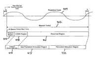
- FIG. 4illustrates an exemplary beacon period synchronized to an exemplary powerline cycle, according to one embodiment of the present invention.
- beacon period 402i.e. the time between two consecutive beacon transmissions
- the beacon periodis substantially equal to two periods of powerline cycle 404 .
- the beacon periodis nominally equal to 33.33 milliseconds (ms).
- beacon Period 402is nominally equal to 40 ms.
- beacon period 402can be precisely equal to two periods of powerline cycle 404 .
- the start of beacon period 402can be offset from the start of a powerline cycle by a fixed duration.
- beacon period 402includes beacon region 406 , CSMA (Carrier Sense Multiple Access) region 408 , and reserved region 410 .
- Beacon region 406includes the beacon, which is generated by a CCo and can include a Preamble, a Frame Control, and a beacon payload.
- the CCoensures that the beacon remains synchronized to the powerline cycle, independent of the CCo local clock frequency.
- Beacon region 406also includes information regarding the duration of CSMA region 408 and reserved region 410 .
- CSMA region 408includes persistent shared CSMA allocation region 416 , which is allocated to connections (i.e. sessions between transmitting and receiving stations) that use CSMA channel-access mechanism.
- CSMA region 408is a contention period (CP) which is also known as CSMA/CA (Carrier Sense Multiple Access/contention access) period.
- Reserved region 410which is the section of beacon period 402 during which only one station has permission to transmit, is further divided into persistent allocation region 412 and non-persistent allocation region 414 .
- Persistent allocation region 412is allocated to connections (i.e. sessions between transmitting and receiving stations), where the connections require QoS (Quality of Service).
- Persistent allocation region 412is a contention free period (CFP) and can utilize TDMA (Time Division Multiple Access) channel access.
- Non-persistent allocation region 414is allocated to one or more of the following:
- channel estimationis a process of measuring the characteristics of a powerline channel that is utilized to adapt the operation of the PHY (e.g. PHY layer 110 in FIG. 1 ) to provide optimal performance.
- the stationestimates the channel between itself and the other station(s) with which it desires to communicate.
- one or more tone mapswhich are lists that indicate the amount of information that can be reliably carried in different tones (portions of the spectrum), are selected for different intervals within the beacon period (e.g. beacon period 402 in FIG. 4 ).
- a tone mapincludes a set (or list) of tones to be used on a particular unicast communication link between two stations in the powerline network.
- the tone mapfurther includes a unique set of modulation methods for all of the tones in the set of tones.
- Channel estimationcan include selection of the modulation method(s) used on each carrier (i.e. tone), selection of the FEC (Forward Error Correction) rate, selection of the guard interval length, and selection of the intervals within the AC line cycle (i.e. the powerline cycle) where a particular tone map setting applies.
- the FEC rate and guard interval lengthcan vary over the powerline cycle period, but they are the same for all carriers at any given time.
- All stations in the powerline networkestablish a default tone map that is valid for reception by the particular station in all of the CSMA and CFP period (i.e. the whole Beacon Period a station may transmit).
- stationsmay establish AC line cycle adapted Tone Maps, i.e. Tone Maps that are valid in portion(s) of the Beacon Period and the underlying AC line cycle.
- a channel estimation procedureenables a transmitting station to obtain tone maps that can be used at various intervals of the powerline cycle while communicating with a particular receiving station.
- Powerline channelsare unique between each transmitting station and receiving station. As a result, the channel estimation procedure must be executed independently between each transmitting station and receiving station.
- the channel estimation procedurealso includes mechanisms for negotiating the number of tone maps that can be used, maintaining lists of valid tone maps, and maintaining the lists of intervals within the powerline cycle where each tone map may be used.
- the channel estimation procedurecan be divided into an initial channel estimation procedure and a dynamic channel adaptation procedure. The transmitting station invokes an initial channel estimation procedure when it needs to transmit data to a particular receiving station and does not have any valid tone maps.
- FIG. 5there is shown exemplary flowchart 500 depicting a method for performing an initial channel estimation procedure between transmitting and receiving stations in a powerline network in accordance with one embodiment of the present invention.
- Certain details and featureshave been left out of flowchart 500 of FIG. 5 that are apparent to a person of ordinary skill in the art.
- a stepmay consist of one or more sub-steps or may involve specialized equipment, as known in the art. While steps 502 through 510 shown in flowchart 500 are sufficient to describe one embodiment of the present invention, other embodiments of the invention may utilize steps different from those shown in flowchart 500 .
- a transmitting station with data to send to a receiving stationdetermines that it (i.e. the transmitting station) has no valid tone maps.
- the transmitting stationinitiates a channel estimation procedure by sending a sound MPDU (MAC Protocol Data Unit) with SRC (Sound Reason Code) set to indicate sounding for initial channel estimation.
- This MPDUwhich is also referred to as an “initial transmission” in the patent application, specifies the maximum number of tone maps that the transmitting station can allocate to this “link.”
- a connectionis decomposed into one or more unidirectional data flows called “links.”
- the sound MPDUis used during channel estimation to estimate the characteristics of the channel. Initial channel estimation can take place in either the CP or the CFP.
- the receiving stationsends a sound MPDU with SAF (Sound ACK Flag) bit in the FC (Frame Control) field appropriately set to acknowledge reception of the sound MPDU from the transmitting station.
- the transmitting stationcontinues to send sound MPDUs to the receiving station until the receiving station indicates that it has sufficient data to generate tone maps.
- the receiving stationcan send a sound MPDU to the transmitting station with the SAF and the SCF (Sound Complete Flag) appropriately set to indicate that it (i.e. the receiving station) has sufficient data to generate the tone maps.
- the receiving stationgenerates a new tone map and sends it to the transmitting station as a default tone map.
- the new tone mapcan be sent in a CEI (Channel Estimation Indication) message having a response type field that indicates that the message includes a default tone map that is generated as a result of the initial channel estimation procedure.
- CEIChannel Estimation Indication
- the receiving stationcan also generate one or more powerline cycle adapted tone maps.
- the transmitting stationmust contend for the channel prior to sending sound MPDUs to the receiving station. Conducting the initial channel estimation procedure in the CP may preclude the transmitting station from transmitting sound MPDUs during certain parts of the powerline cycle. Similarly, if the initial channel estimation procedure is performed in the CFP, the transmitting station may lack sufficient allocation to span a complete powerline cycle. In either case, the receiving station is required to provide a tone map referred to as the default tone map that is valid for all portions of the beacon period (or powerline cycle).
- a dynamic channel adaptation procedurecan be performed by the receiving station after the initial channel estimation procedure has been performed.
- the dynamic channel adaptation procedurecan result in dynamic updates to the default tone map (i.e. replacing an existing default tone map with a new default tone map).
- This procedurecan also result in the generation of powerline cycle adapted tone maps that are valid at various intervals of the powerline cycle, where some of powerline cycle adapted tone maps may replace existing tone maps.
- powerline cycle adapted tone mapsare fine tuned for channel characteristics within a specific interval of the powerline cycle.
- Tone mapsneed to be updated and refreshed on a regular basis, otherwise they are declared as stale, and cannot be used in connections. This adaptation is needed to capture changes of the channel resulting from removal or addition of equipment in the neighborhood of the receiving or transmitting station, for example.
- the health of an active linkis constantly monitored by both the receiving and transmitting stations (the transmitting station can receive feedback from the receiving station by means of the Selective ACK mechanism).
- the stationscan request more resources from the CCo. More resources may be needed, for example, because the channel has degraded or because the traffic presented to the transmitting station by the application has increased.
- the stationscan indicate their resource needs to the CCo through special fields in the FC (Frame Control) field of each transmission.
- FCFrame Control
- Each transmission on the channelstarts with a special portion called the Frame Control (FC), which provides special information to the receiving station (e.g. what tone map is used in the modulation of the payload, or what code rate is used for error correction).
- FCFrame Control
- One of the fields in the FCprovides an indication of how many blocks are waiting for transmission in the transmitting station. If the number of blocks waiting for transmission appears excessive (i.e. if the transmitting station is suffering from congestion), the CCo, which can monitor the FC from all the transmissions in the powerline network, can allocate more resources to that connection. Additional allocations can be temporary (e.g.
- Allocation changescan also be longer term to deal with changes in the channel to which the PHY layer cannot simply adapt, or with changes in the traffic load caused by a particular application.
- FIG. 6Aillustrates an exemplary MPDU format for use by HPAV system 100 in FIG. 1 .
- long MPDU 602includes frame control block 604 and MPDU payload 606 .
- Long MPDU 602refers to an MPDU that carries payload information in addition to frame control information and is used in AV-only mode.
- Frame control block 604which can comprise 128 bits, for example, includes frame control information and MPDU payload 606 includes payload information.
- FIG. 6Billustrates an exemplary MPDU format for use by HPAV system 100 in FIG. 1 .
- short MPDU 650only includes a frame control block, which includes frame control information.
- the frame control blockcan comprise 128 bits.
- the present inventionprovides an HPAV system including stations that communicate via a powerline in a powerline network, where each of the stations can be configured to generate one or more tone maps for communicating with each of the other stations, and where the tone maps indicate an amount of information that can be reliably carried in different tones.
- Each of the stationscan be further configured to monitor its bandwidth needs and communicate its bandwidth needs to a CCo (central coordinator) for allocation of additional resources.
- CCocentral coordinator
Landscapes
- Engineering & Computer Science (AREA)
- Computer Networks & Wireless Communication (AREA)
- Signal Processing (AREA)
- Power Engineering (AREA)
- Small-Scale Networks (AREA)
- Cable Transmission Systems, Equalization Of Radio And Reduction Of Echo (AREA)
Abstract
Description
| TABLE 1 | ||
| Physical Networks (PhyNets) in . . . | ||
| Station | FIG. 2A | FIG. 2B | FIG. 2C |
| A | {A, B, C, D, CCo1} | {A, B, CCo1} | {A, B, CCo1} |
| B | {A, B, C, D, CCo1} | {A, B, CCo1} | {A, B, CCo1} |
| C | {A, B, C, D, CCo1} | {C, D, CCo2} | {C, D, CCo1} |
| D | {A, B, C, D, CCo1} | {C, D, CCo2} | {C, D} |
| CCo1 | {A, B, C, D, CCo1} | {A, B, CCo1, CCo2} | {A, B, C, CCo1} |
| CCo2 | N/A | {C, D, CCo1, CCo2} | N/A |
Claims (18)
Priority Applications (1)
| Application Number | Priority Date | Filing Date | Title |
|---|---|---|---|
| US11/492,505US8737420B2 (en) | 2005-07-27 | 2006-07-24 | Bandwidth management in a powerline network |
Applications Claiming Priority (5)
| Application Number | Priority Date | Filing Date | Title |
|---|---|---|---|
| US70271705P | 2005-07-27 | 2005-07-27 | |
| US70323605P | 2005-07-27 | 2005-07-27 | |
| US70331705P | 2005-07-27 | 2005-07-27 | |
| US70572005P | 2005-08-02 | 2005-08-02 | |
| US11/492,505US8737420B2 (en) | 2005-07-27 | 2006-07-24 | Bandwidth management in a powerline network |
Publications (2)
| Publication Number | Publication Date |
|---|---|
| US20070025386A1 US20070025386A1 (en) | 2007-02-01 |
| US8737420B2true US8737420B2 (en) | 2014-05-27 |
Family
ID=37694221
Family Applications (1)
| Application Number | Title | Priority Date | Filing Date |
|---|---|---|---|
| US11/492,505Active2028-08-19US8737420B2 (en) | 2005-07-27 | 2006-07-24 | Bandwidth management in a powerline network |
Country Status (1)
| Country | Link |
|---|---|
| US (1) | US8737420B2 (en) |
Cited By (1)
| Publication number | Priority date | Publication date | Assignee | Title |
|---|---|---|---|---|
| US20130215885A1 (en)* | 2012-02-22 | 2013-08-22 | Kumaran Vijayasankar | Transmission of Segmented Frames in Power Line Communication |
Families Citing this family (197)
| Publication number | Priority date | Publication date | Assignee | Title |
|---|---|---|---|---|
| US8090857B2 (en) | 2003-11-24 | 2012-01-03 | Qualcomm Atheros, Inc. | Medium access control layer that encapsulates data from a plurality of received data units into a plurality of independently transmittable blocks |
| US8175190B2 (en) | 2005-07-27 | 2012-05-08 | Qualcomm Atheros, Inc. | Managing spectra of modulated signals in a communication network |
| WO2007016641A2 (en)* | 2005-08-02 | 2007-02-08 | Comhouse Wireless, Lp | Methods of remotely identifying, suppressing and/or disabling wireless devices of interest |
| US8767595B2 (en)* | 2005-08-02 | 2014-07-01 | L-3 Communications Corporation | Enhanced methods of cellular environment detection when interoperating with timed interfers |
| EP1770870B1 (en)* | 2005-10-03 | 2019-04-03 | Avago Technologies International Sales Pte. Limited | Powerline communication device and method |
| US8213895B2 (en)* | 2005-10-03 | 2012-07-03 | Broadcom Europe Limited | Multi-wideband communications over multiple mediums within a network |
| US7808985B2 (en)* | 2006-11-21 | 2010-10-05 | Gigle Networks Sl | Network repeater |
| US8406239B2 (en)* | 2005-10-03 | 2013-03-26 | Broadcom Corporation | Multi-wideband communications over multiple mediums |
| US20070076666A1 (en)* | 2005-10-03 | 2007-04-05 | Riveiro Juan C | Multi-Wideband Communications over Power Lines |
| US20080159358A1 (en)* | 2007-01-02 | 2008-07-03 | David Ruiz | Unknown Destination Traffic Repetition |
| US7876717B2 (en)* | 2005-12-09 | 2011-01-25 | Sony Corporation | System and method for providing access in powerline communications (PLC) network |
| KR101217628B1 (en)* | 2006-02-16 | 2013-01-02 | 삼성전자주식회사 | Method for packet aggregation in power line communication network and apparatus therefor |
| US7860146B2 (en)* | 2006-07-06 | 2010-12-28 | Gigle Networks, Inc. | Adaptative multi-carrier code division multiple access |
| US8885814B2 (en) | 2006-07-25 | 2014-11-11 | Broadcom Europe Limited | Feedback impedance control for driving a signal |
| US8755770B2 (en)* | 2006-08-01 | 2014-06-17 | L-3 Communications Corporation | Methods for identifying wireless devices connected to potentially threatening devices |
| US20100226308A1 (en)* | 2006-08-15 | 2010-09-09 | Comhouse Wireless Lp | node- arbitrated media access control protocol for ad hoc broadcast networks carrying ephemeral information |
| PL2271165T3 (en) | 2006-08-21 | 2014-01-31 | Interdigital Tech Corp | Dynamic resource allocation scheduling and signaling for a variable data rate service in LTE |
| US20080298382A1 (en)* | 2007-05-31 | 2008-12-04 | Matsushita Electric Industrial Co., Ltd. | Method, apparatus and system for progressive refinementof channel estimation to increase network data throughput and reliability |
| KR101013439B1 (en)* | 2008-02-26 | 2011-02-14 | 삼성전자주식회사 | Apparatus and method for estimating map message size in broadband wireless communication system |
| US7929547B2 (en)* | 2008-03-06 | 2011-04-19 | Lantiq Deutschland Gmbh | Networks having plurality of nodes |
| US7795973B2 (en) | 2008-10-13 | 2010-09-14 | Gigle Networks Ltd. | Programmable gain amplifier |
| US7956689B2 (en)* | 2008-10-13 | 2011-06-07 | Broadcom Corporation | Programmable gain amplifier and transconductance compensation system |
| US9325618B1 (en) | 2008-12-31 | 2016-04-26 | Qualcomm Incorporated | Dynamic management of shared transmission opportunities |
| US8526395B2 (en)* | 2009-09-04 | 2013-09-03 | L-3 Communications Corporation | Using code channel overrides to suppress CDMA wireless devices |
| US9385782B1 (en) | 2010-01-08 | 2016-07-05 | Qualcomm Incorporated | Communication between network nodes |
| US20120027062A1 (en)* | 2010-07-28 | 2012-02-02 | Battelle Energy Alliance, Llc | Apparatuses and methods for setting an adaptive frequency band for power line communciation |
| US8457125B2 (en)* | 2010-08-24 | 2013-06-04 | Intel Corporation | G.hn network node and method for operating a G.hn network node in the presence of a homeplug network |
| US9026813B2 (en)* | 2010-11-22 | 2015-05-05 | Qualcomm Incorporated | Establishing a power charging association on a powerline network |
| US9538128B2 (en)* | 2011-02-28 | 2017-01-03 | Cisco Technology, Inc. | System and method for managing video processing in a network environment |
| US8964786B2 (en)* | 2011-04-08 | 2015-02-24 | Texas Instruments Incorporated | Communications in beacon-enabled networks |
| US9113347B2 (en) | 2012-12-05 | 2015-08-18 | At&T Intellectual Property I, Lp | Backhaul link for distributed antenna system |
| US10009065B2 (en) | 2012-12-05 | 2018-06-26 | At&T Intellectual Property I, L.P. | Backhaul link for distributed antenna system |
| US9166853B2 (en) | 2013-01-10 | 2015-10-20 | Qualcomm Incorporated | Rate adaptation for data communication |
| US9071390B2 (en) | 2013-01-10 | 2015-06-30 | Qualcomm Incorporated | Adjusting physical layer transmission properties |
| US9787360B2 (en) | 2013-01-28 | 2017-10-10 | Sigma Designs Israel S.D.I. Ltd. | Zero crossing indicator device |
| US9537641B2 (en) | 2013-05-30 | 2017-01-03 | Qualcomm Incorporated | Channel adaptation to compensate for interference from neighbor powerline communication networks |
| US9525524B2 (en) | 2013-05-31 | 2016-12-20 | At&T Intellectual Property I, L.P. | Remote distributed antenna system |
| US9999038B2 (en) | 2013-05-31 | 2018-06-12 | At&T Intellectual Property I, L.P. | Remote distributed antenna system |
| US9258093B2 (en)* | 2013-10-25 | 2016-02-09 | Qualcomm Incorporated | Estimating tone maps in a communication network |
| US8897697B1 (en) | 2013-11-06 | 2014-11-25 | At&T Intellectual Property I, Lp | Millimeter-wave surface-wave communications |
| US9209902B2 (en) | 2013-12-10 | 2015-12-08 | At&T Intellectual Property I, L.P. | Quasi-optical coupler |
| US9692101B2 (en) | 2014-08-26 | 2017-06-27 | At&T Intellectual Property I, L.P. | Guided wave couplers for coupling electromagnetic waves between a waveguide surface and a surface of a wire |
| US9768833B2 (en) | 2014-09-15 | 2017-09-19 | At&T Intellectual Property I, L.P. | Method and apparatus for sensing a condition in a transmission medium of electromagnetic waves |
| US10063280B2 (en) | 2014-09-17 | 2018-08-28 | At&T Intellectual Property I, L.P. | Monitoring and mitigating conditions in a communication network |
| US9628854B2 (en) | 2014-09-29 | 2017-04-18 | At&T Intellectual Property I, L.P. | Method and apparatus for distributing content in a communication network |
| US9615269B2 (en) | 2014-10-02 | 2017-04-04 | At&T Intellectual Property I, L.P. | Method and apparatus that provides fault tolerance in a communication network |
| US9685992B2 (en) | 2014-10-03 | 2017-06-20 | At&T Intellectual Property I, L.P. | Circuit panel network and methods thereof |
| US9503189B2 (en) | 2014-10-10 | 2016-11-22 | At&T Intellectual Property I, L.P. | Method and apparatus for arranging communication sessions in a communication system |
| US9973299B2 (en) | 2014-10-14 | 2018-05-15 | At&T Intellectual Property I, L.P. | Method and apparatus for adjusting a mode of communication in a communication network |
| US9762289B2 (en) | 2014-10-14 | 2017-09-12 | At&T Intellectual Property I, L.P. | Method and apparatus for transmitting or receiving signals in a transportation system |
| US9564947B2 (en) | 2014-10-21 | 2017-02-07 | At&T Intellectual Property I, L.P. | Guided-wave transmission device with diversity and methods for use therewith |
| US9780834B2 (en) | 2014-10-21 | 2017-10-03 | At&T Intellectual Property I, L.P. | Method and apparatus for transmitting electromagnetic waves |
| US9577306B2 (en) | 2014-10-21 | 2017-02-21 | At&T Intellectual Property I, L.P. | Guided-wave transmission device and methods for use therewith |
| US9627768B2 (en) | 2014-10-21 | 2017-04-18 | At&T Intellectual Property I, L.P. | Guided-wave transmission device with non-fundamental mode propagation and methods for use therewith |
| US9312919B1 (en) | 2014-10-21 | 2016-04-12 | At&T Intellectual Property I, Lp | Transmission device with impairment compensation and methods for use therewith |
| US9653770B2 (en) | 2014-10-21 | 2017-05-16 | At&T Intellectual Property I, L.P. | Guided wave coupler, coupling module and methods for use therewith |
| US9769020B2 (en) | 2014-10-21 | 2017-09-19 | At&T Intellectual Property I, L.P. | Method and apparatus for responding to events affecting communications in a communication network |
| US9520945B2 (en) | 2014-10-21 | 2016-12-13 | At&T Intellectual Property I, L.P. | Apparatus for providing communication services and methods thereof |
| US10243784B2 (en) | 2014-11-20 | 2019-03-26 | At&T Intellectual Property I, L.P. | System for generating topology information and methods thereof |
| US10340573B2 (en) | 2016-10-26 | 2019-07-02 | At&T Intellectual Property I, L.P. | Launcher with cylindrical coupling device and methods for use therewith |
| US9461706B1 (en) | 2015-07-31 | 2016-10-04 | At&T Intellectual Property I, Lp | Method and apparatus for exchanging communication signals |
| US9680670B2 (en) | 2014-11-20 | 2017-06-13 | At&T Intellectual Property I, L.P. | Transmission device with channel equalization and control and methods for use therewith |
| US9544006B2 (en) | 2014-11-20 | 2017-01-10 | At&T Intellectual Property I, L.P. | Transmission device with mode division multiplexing and methods for use therewith |
| US10009067B2 (en) | 2014-12-04 | 2018-06-26 | At&T Intellectual Property I, L.P. | Method and apparatus for configuring a communication interface |
| US9800327B2 (en) | 2014-11-20 | 2017-10-24 | At&T Intellectual Property I, L.P. | Apparatus for controlling operations of a communication device and methods thereof |
| US9654173B2 (en) | 2014-11-20 | 2017-05-16 | At&T Intellectual Property I, L.P. | Apparatus for powering a communication device and methods thereof |
| US9742462B2 (en) | 2014-12-04 | 2017-08-22 | At&T Intellectual Property I, L.P. | Transmission medium and communication interfaces and methods for use therewith |
| US9954287B2 (en) | 2014-11-20 | 2018-04-24 | At&T Intellectual Property I, L.P. | Apparatus for converting wireless signals and electromagnetic waves and methods thereof |
| US9997819B2 (en) | 2015-06-09 | 2018-06-12 | At&T Intellectual Property I, L.P. | Transmission medium and method for facilitating propagation of electromagnetic waves via a core |
| US20160149689A1 (en)* | 2014-11-24 | 2016-05-26 | Panasonic Intellectual Property Management Co., Ltd. | Communication apparatus and communication method |
| US10144036B2 (en) | 2015-01-30 | 2018-12-04 | At&T Intellectual Property I, L.P. | Method and apparatus for mitigating interference affecting a propagation of electromagnetic waves guided by a transmission medium |
| US9876570B2 (en) | 2015-02-20 | 2018-01-23 | At&T Intellectual Property I, Lp | Guided-wave transmission device with non-fundamental mode propagation and methods for use therewith |
| US9749013B2 (en) | 2015-03-17 | 2017-08-29 | At&T Intellectual Property I, L.P. | Method and apparatus for reducing attenuation of electromagnetic waves guided by a transmission medium |
| US10224981B2 (en) | 2015-04-24 | 2019-03-05 | At&T Intellectual Property I, Lp | Passive electrical coupling device and methods for use therewith |
| US9705561B2 (en) | 2015-04-24 | 2017-07-11 | At&T Intellectual Property I, L.P. | Directional coupling device and methods for use therewith |
| US9793954B2 (en) | 2015-04-28 | 2017-10-17 | At&T Intellectual Property I, L.P. | Magnetic coupling device and methods for use therewith |
| US9948354B2 (en) | 2015-04-28 | 2018-04-17 | At&T Intellectual Property I, L.P. | Magnetic coupling device with reflective plate and methods for use therewith |
| US9490869B1 (en) | 2015-05-14 | 2016-11-08 | At&T Intellectual Property I, L.P. | Transmission medium having multiple cores and methods for use therewith |
| US9748626B2 (en) | 2015-05-14 | 2017-08-29 | At&T Intellectual Property I, L.P. | Plurality of cables having different cross-sectional shapes which are bundled together to form a transmission medium |
| US9871282B2 (en) | 2015-05-14 | 2018-01-16 | At&T Intellectual Property I, L.P. | At least one transmission medium having a dielectric surface that is covered at least in part by a second dielectric |
| US10679767B2 (en) | 2015-05-15 | 2020-06-09 | At&T Intellectual Property I, L.P. | Transmission medium having a conductive material and methods for use therewith |
| US10650940B2 (en) | 2015-05-15 | 2020-05-12 | At&T Intellectual Property I, L.P. | Transmission medium having a conductive material and methods for use therewith |
| US9917341B2 (en) | 2015-05-27 | 2018-03-13 | At&T Intellectual Property I, L.P. | Apparatus and method for launching electromagnetic waves and for modifying radial dimensions of the propagating electromagnetic waves |
| US9912381B2 (en) | 2015-06-03 | 2018-03-06 | At&T Intellectual Property I, Lp | Network termination and methods for use therewith |
| US10154493B2 (en) | 2015-06-03 | 2018-12-11 | At&T Intellectual Property I, L.P. | Network termination and methods for use therewith |
| US10103801B2 (en) | 2015-06-03 | 2018-10-16 | At&T Intellectual Property I, L.P. | Host node device and methods for use therewith |
| US9866309B2 (en) | 2015-06-03 | 2018-01-09 | At&T Intellectual Property I, Lp | Host node device and methods for use therewith |
| US10812174B2 (en) | 2015-06-03 | 2020-10-20 | At&T Intellectual Property I, L.P. | Client node device and methods for use therewith |
| US10348391B2 (en) | 2015-06-03 | 2019-07-09 | At&T Intellectual Property I, L.P. | Client node device with frequency conversion and methods for use therewith |
| US9913139B2 (en) | 2015-06-09 | 2018-03-06 | At&T Intellectual Property I, L.P. | Signal fingerprinting for authentication of communicating devices |
| US10142086B2 (en) | 2015-06-11 | 2018-11-27 | At&T Intellectual Property I, L.P. | Repeater and methods for use therewith |
| US9608692B2 (en) | 2015-06-11 | 2017-03-28 | At&T Intellectual Property I, L.P. | Repeater and methods for use therewith |
| US9820146B2 (en) | 2015-06-12 | 2017-11-14 | At&T Intellectual Property I, L.P. | Method and apparatus for authentication and identity management of communicating devices |
| US9667317B2 (en) | 2015-06-15 | 2017-05-30 | At&T Intellectual Property I, L.P. | Method and apparatus for providing security using network traffic adjustments |
| US9509415B1 (en) | 2015-06-25 | 2016-11-29 | At&T Intellectual Property I, L.P. | Methods and apparatus for inducing a fundamental wave mode on a transmission medium |
| US9640850B2 (en) | 2015-06-25 | 2017-05-02 | At&T Intellectual Property I, L.P. | Methods and apparatus for inducing a non-fundamental wave mode on a transmission medium |
| US9865911B2 (en) | 2015-06-25 | 2018-01-09 | At&T Intellectual Property I, L.P. | Waveguide system for slot radiating first electromagnetic waves that are combined into a non-fundamental wave mode second electromagnetic wave on a transmission medium |
| US10033107B2 (en) | 2015-07-14 | 2018-07-24 | At&T Intellectual Property I, L.P. | Method and apparatus for coupling an antenna to a device |
| US9628116B2 (en) | 2015-07-14 | 2017-04-18 | At&T Intellectual Property I, L.P. | Apparatus and methods for transmitting wireless signals |
| US10033108B2 (en) | 2015-07-14 | 2018-07-24 | At&T Intellectual Property I, L.P. | Apparatus and methods for generating an electromagnetic wave having a wave mode that mitigates interference |
| US9836957B2 (en) | 2015-07-14 | 2017-12-05 | At&T Intellectual Property I, L.P. | Method and apparatus for communicating with premises equipment |
| US9882257B2 (en) | 2015-07-14 | 2018-01-30 | At&T Intellectual Property I, L.P. | Method and apparatus for launching a wave mode that mitigates interference |
| US10205655B2 (en) | 2015-07-14 | 2019-02-12 | At&T Intellectual Property I, L.P. | Apparatus and methods for communicating utilizing an antenna array and multiple communication paths |
| US9722318B2 (en) | 2015-07-14 | 2017-08-01 | At&T Intellectual Property I, L.P. | Method and apparatus for coupling an antenna to a device |
| US9853342B2 (en) | 2015-07-14 | 2017-12-26 | At&T Intellectual Property I, L.P. | Dielectric transmission medium connector and methods for use therewith |
| US10044409B2 (en) | 2015-07-14 | 2018-08-07 | At&T Intellectual Property I, L.P. | Transmission medium and methods for use therewith |
| US10148016B2 (en) | 2015-07-14 | 2018-12-04 | At&T Intellectual Property I, L.P. | Apparatus and methods for communicating utilizing an antenna array |
| US10170840B2 (en) | 2015-07-14 | 2019-01-01 | At&T Intellectual Property I, L.P. | Apparatus and methods for sending or receiving electromagnetic signals |
| US10341142B2 (en) | 2015-07-14 | 2019-07-02 | At&T Intellectual Property I, L.P. | Apparatus and methods for generating non-interfering electromagnetic waves on an uninsulated conductor |
| US9847566B2 (en) | 2015-07-14 | 2017-12-19 | At&T Intellectual Property I, L.P. | Method and apparatus for adjusting a field of a signal to mitigate interference |
| US10320586B2 (en) | 2015-07-14 | 2019-06-11 | At&T Intellectual Property I, L.P. | Apparatus and methods for generating non-interfering electromagnetic waves on an insulated transmission medium |
| US9608740B2 (en) | 2015-07-15 | 2017-03-28 | At&T Intellectual Property I, L.P. | Method and apparatus for launching a wave mode that mitigates interference |
| US9793951B2 (en) | 2015-07-15 | 2017-10-17 | At&T Intellectual Property I, L.P. | Method and apparatus for launching a wave mode that mitigates interference |
| US10090606B2 (en) | 2015-07-15 | 2018-10-02 | At&T Intellectual Property I, L.P. | Antenna system with dielectric array and methods for use therewith |
| US9871283B2 (en) | 2015-07-23 | 2018-01-16 | At&T Intellectual Property I, Lp | Transmission medium having a dielectric core comprised of plural members connected by a ball and socket configuration |
| US9912027B2 (en) | 2015-07-23 | 2018-03-06 | At&T Intellectual Property I, L.P. | Method and apparatus for exchanging communication signals |
| US9948333B2 (en) | 2015-07-23 | 2018-04-17 | At&T Intellectual Property I, L.P. | Method and apparatus for wireless communications to mitigate interference |
| US9749053B2 (en) | 2015-07-23 | 2017-08-29 | At&T Intellectual Property I, L.P. | Node device, repeater and methods for use therewith |
| US10784670B2 (en) | 2015-07-23 | 2020-09-22 | At&T Intellectual Property I, L.P. | Antenna support for aligning an antenna |
| US9735833B2 (en) | 2015-07-31 | 2017-08-15 | At&T Intellectual Property I, L.P. | Method and apparatus for communications management in a neighborhood network |
| US9967173B2 (en) | 2015-07-31 | 2018-05-08 | At&T Intellectual Property I, L.P. | Method and apparatus for authentication and identity management of communicating devices |
| US10020587B2 (en) | 2015-07-31 | 2018-07-10 | At&T Intellectual Property I, L.P. | Radial antenna and methods for use therewith |
| US9904535B2 (en) | 2015-09-14 | 2018-02-27 | At&T Intellectual Property I, L.P. | Method and apparatus for distributing software |
| US10009063B2 (en) | 2015-09-16 | 2018-06-26 | At&T Intellectual Property I, L.P. | Method and apparatus for use with a radio distributed antenna system having an out-of-band reference signal |
| US9705571B2 (en) | 2015-09-16 | 2017-07-11 | At&T Intellectual Property I, L.P. | Method and apparatus for use with a radio distributed antenna system |
| US10009901B2 (en) | 2015-09-16 | 2018-06-26 | At&T Intellectual Property I, L.P. | Method, apparatus, and computer-readable storage medium for managing utilization of wireless resources between base stations |
| US10136434B2 (en) | 2015-09-16 | 2018-11-20 | At&T Intellectual Property I, L.P. | Method and apparatus for use with a radio distributed antenna system having an ultra-wideband control channel |
| US10079661B2 (en) | 2015-09-16 | 2018-09-18 | At&T Intellectual Property I, L.P. | Method and apparatus for use with a radio distributed antenna system having a clock reference |
| US10051629B2 (en) | 2015-09-16 | 2018-08-14 | At&T Intellectual Property I, L.P. | Method and apparatus for use with a radio distributed antenna system having an in-band reference signal |
| US9769128B2 (en) | 2015-09-28 | 2017-09-19 | At&T Intellectual Property I, L.P. | Method and apparatus for encryption of communications over a network |
| US9729197B2 (en) | 2015-10-01 | 2017-08-08 | At&T Intellectual Property I, L.P. | Method and apparatus for communicating network management traffic over a network |
| US9876264B2 (en) | 2015-10-02 | 2018-01-23 | At&T Intellectual Property I, Lp | Communication system, guided wave switch and methods for use therewith |
| US9882277B2 (en) | 2015-10-02 | 2018-01-30 | At&T Intellectual Property I, Lp | Communication device and antenna assembly with actuated gimbal mount |
| US10074890B2 (en) | 2015-10-02 | 2018-09-11 | At&T Intellectual Property I, L.P. | Communication device and antenna with integrated light assembly |
| US10665942B2 (en) | 2015-10-16 | 2020-05-26 | At&T Intellectual Property I, L.P. | Method and apparatus for adjusting wireless communications |
| US10051483B2 (en) | 2015-10-16 | 2018-08-14 | At&T Intellectual Property I, L.P. | Method and apparatus for directing wireless signals |
| US10355367B2 (en) | 2015-10-16 | 2019-07-16 | At&T Intellectual Property I, L.P. | Antenna structure for exchanging wireless signals |
| US9912419B1 (en) | 2016-08-24 | 2018-03-06 | At&T Intellectual Property I, L.P. | Method and apparatus for managing a fault in a distributed antenna system |
| US9860075B1 (en) | 2016-08-26 | 2018-01-02 | At&T Intellectual Property I, L.P. | Method and communication node for broadband distribution |
| US10291311B2 (en) | 2016-09-09 | 2019-05-14 | At&T Intellectual Property I, L.P. | Method and apparatus for mitigating a fault in a distributed antenna system |
| US11032819B2 (en) | 2016-09-15 | 2021-06-08 | At&T Intellectual Property I, L.P. | Method and apparatus for use with a radio distributed antenna system having a control channel reference signal |
| US10135147B2 (en) | 2016-10-18 | 2018-11-20 | At&T Intellectual Property I, L.P. | Apparatus and methods for launching guided waves via an antenna |
| US10340600B2 (en) | 2016-10-18 | 2019-07-02 | At&T Intellectual Property I, L.P. | Apparatus and methods for launching guided waves via plural waveguide systems |
| US10135146B2 (en) | 2016-10-18 | 2018-11-20 | At&T Intellectual Property I, L.P. | Apparatus and methods for launching guided waves via circuits |
| US10811767B2 (en) | 2016-10-21 | 2020-10-20 | At&T Intellectual Property I, L.P. | System and dielectric antenna with convex dielectric radome |
| US9876605B1 (en) | 2016-10-21 | 2018-01-23 | At&T Intellectual Property I, L.P. | Launcher and coupling system to support desired guided wave mode |
| US9991580B2 (en) | 2016-10-21 | 2018-06-05 | At&T Intellectual Property I, L.P. | Launcher and coupling system for guided wave mode cancellation |
| US10374316B2 (en) | 2016-10-21 | 2019-08-06 | At&T Intellectual Property I, L.P. | System and dielectric antenna with non-uniform dielectric |
| US10312567B2 (en) | 2016-10-26 | 2019-06-04 | At&T Intellectual Property I, L.P. | Launcher with planar strip antenna and methods for use therewith |
| US10225025B2 (en) | 2016-11-03 | 2019-03-05 | At&T Intellectual Property I, L.P. | Method and apparatus for detecting a fault in a communication system |
| US10224634B2 (en) | 2016-11-03 | 2019-03-05 | At&T Intellectual Property I, L.P. | Methods and apparatus for adjusting an operational characteristic of an antenna |
| US10291334B2 (en) | 2016-11-03 | 2019-05-14 | At&T Intellectual Property I, L.P. | System for detecting a fault in a communication system |
| US10498044B2 (en) | 2016-11-03 | 2019-12-03 | At&T Intellectual Property I, L.P. | Apparatus for configuring a surface of an antenna |
| US10178445B2 (en) | 2016-11-23 | 2019-01-08 | At&T Intellectual Property I, L.P. | Methods, devices, and systems for load balancing between a plurality of waveguides |
| US10535928B2 (en) | 2016-11-23 | 2020-01-14 | At&T Intellectual Property I, L.P. | Antenna system and methods for use therewith |
| US10090594B2 (en) | 2016-11-23 | 2018-10-02 | At&T Intellectual Property I, L.P. | Antenna system having structural configurations for assembly |
| US10340601B2 (en) | 2016-11-23 | 2019-07-02 | At&T Intellectual Property I, L.P. | Multi-antenna system and methods for use therewith |
| US10340603B2 (en) | 2016-11-23 | 2019-07-02 | At&T Intellectual Property I, L.P. | Antenna system having shielded structural configurations for assembly |
| US10361489B2 (en) | 2016-12-01 | 2019-07-23 | At&T Intellectual Property I, L.P. | Dielectric dish antenna system and methods for use therewith |
| US10305190B2 (en) | 2016-12-01 | 2019-05-28 | At&T Intellectual Property I, L.P. | Reflecting dielectric antenna system and methods for use therewith |
| US10637149B2 (en) | 2016-12-06 | 2020-04-28 | At&T Intellectual Property I, L.P. | Injection molded dielectric antenna and methods for use therewith |
| US9927517B1 (en) | 2016-12-06 | 2018-03-27 | At&T Intellectual Property I, L.P. | Apparatus and methods for sensing rainfall |
| US10382976B2 (en) | 2016-12-06 | 2019-08-13 | At&T Intellectual Property I, L.P. | Method and apparatus for managing wireless communications based on communication paths and network device positions |
| US10020844B2 (en) | 2016-12-06 | 2018-07-10 | T&T Intellectual Property I, L.P. | Method and apparatus for broadcast communication via guided waves |
| US10326494B2 (en) | 2016-12-06 | 2019-06-18 | At&T Intellectual Property I, L.P. | Apparatus for measurement de-embedding and methods for use therewith |
| US10819035B2 (en) | 2016-12-06 | 2020-10-27 | At&T Intellectual Property I, L.P. | Launcher with helical antenna and methods for use therewith |
| US10135145B2 (en) | 2016-12-06 | 2018-11-20 | At&T Intellectual Property I, L.P. | Apparatus and methods for generating an electromagnetic wave along a transmission medium |
| US10727599B2 (en) | 2016-12-06 | 2020-07-28 | At&T Intellectual Property I, L.P. | Launcher with slot antenna and methods for use therewith |
| US10439675B2 (en) | 2016-12-06 | 2019-10-08 | At&T Intellectual Property I, L.P. | Method and apparatus for repeating guided wave communication signals |
| US10694379B2 (en) | 2016-12-06 | 2020-06-23 | At&T Intellectual Property I, L.P. | Waveguide system with device-based authentication and methods for use therewith |
| US10755542B2 (en) | 2016-12-06 | 2020-08-25 | At&T Intellectual Property I, L.P. | Method and apparatus for surveillance via guided wave communication |
| US10547348B2 (en) | 2016-12-07 | 2020-01-28 | At&T Intellectual Property I, L.P. | Method and apparatus for switching transmission mediums in a communication system |
| US10359749B2 (en) | 2016-12-07 | 2019-07-23 | At&T Intellectual Property I, L.P. | Method and apparatus for utilities management via guided wave communication |
| US10243270B2 (en) | 2016-12-07 | 2019-03-26 | At&T Intellectual Property I, L.P. | Beam adaptive multi-feed dielectric antenna system and methods for use therewith |
| US10446936B2 (en) | 2016-12-07 | 2019-10-15 | At&T Intellectual Property I, L.P. | Multi-feed dielectric antenna system and methods for use therewith |
| US9893795B1 (en) | 2016-12-07 | 2018-02-13 | At&T Intellectual Property I, Lp | Method and repeater for broadband distribution |
| US10389029B2 (en) | 2016-12-07 | 2019-08-20 | At&T Intellectual Property I, L.P. | Multi-feed dielectric antenna system with core selection and methods for use therewith |
| US10027397B2 (en) | 2016-12-07 | 2018-07-17 | At&T Intellectual Property I, L.P. | Distributed antenna system and methods for use therewith |
| US10139820B2 (en) | 2016-12-07 | 2018-11-27 | At&T Intellectual Property I, L.P. | Method and apparatus for deploying equipment of a communication system |
| US10168695B2 (en) | 2016-12-07 | 2019-01-01 | At&T Intellectual Property I, L.P. | Method and apparatus for controlling an unmanned aircraft |
| US10601494B2 (en) | 2016-12-08 | 2020-03-24 | At&T Intellectual Property I, L.P. | Dual-band communication device and method for use therewith |
| US10777873B2 (en) | 2016-12-08 | 2020-09-15 | At&T Intellectual Property I, L.P. | Method and apparatus for mounting network devices |
| US9998870B1 (en) | 2016-12-08 | 2018-06-12 | At&T Intellectual Property I, L.P. | Method and apparatus for proximity sensing |
| US10411356B2 (en) | 2016-12-08 | 2019-09-10 | At&T Intellectual Property I, L.P. | Apparatus and methods for selectively targeting communication devices with an antenna array |
| US10326689B2 (en) | 2016-12-08 | 2019-06-18 | At&T Intellectual Property I, L.P. | Method and system for providing alternative communication paths |
| US10530505B2 (en) | 2016-12-08 | 2020-01-07 | At&T Intellectual Property I, L.P. | Apparatus and methods for launching electromagnetic waves along a transmission medium |
| US10389037B2 (en) | 2016-12-08 | 2019-08-20 | At&T Intellectual Property I, L.P. | Apparatus and methods for selecting sections of an antenna array and use therewith |
| US10069535B2 (en) | 2016-12-08 | 2018-09-04 | At&T Intellectual Property I, L.P. | Apparatus and methods for launching electromagnetic waves having a certain electric field structure |
| US10938108B2 (en) | 2016-12-08 | 2021-03-02 | At&T Intellectual Property I, L.P. | Frequency selective multi-feed dielectric antenna system and methods for use therewith |
| US10103422B2 (en) | 2016-12-08 | 2018-10-16 | At&T Intellectual Property I, L.P. | Method and apparatus for mounting network devices |
| US9911020B1 (en) | 2016-12-08 | 2018-03-06 | At&T Intellectual Property I, L.P. | Method and apparatus for tracking via a radio frequency identification device |
| US10916969B2 (en) | 2016-12-08 | 2021-02-09 | At&T Intellectual Property I, L.P. | Method and apparatus for providing power using an inductive coupling |
| US10340983B2 (en) | 2016-12-09 | 2019-07-02 | At&T Intellectual Property I, L.P. | Method and apparatus for surveying remote sites via guided wave communications |
| US9838896B1 (en) | 2016-12-09 | 2017-12-05 | At&T Intellectual Property I, L.P. | Method and apparatus for assessing network coverage |
| US10264586B2 (en) | 2016-12-09 | 2019-04-16 | At&T Mobility Ii Llc | Cloud-based packet controller and methods for use therewith |
| US9973940B1 (en) | 2017-02-27 | 2018-05-15 | At&T Intellectual Property I, L.P. | Apparatus and methods for dynamic impedance matching of a guided wave launcher |
| US10298293B2 (en) | 2017-03-13 | 2019-05-21 | At&T Intellectual Property I, L.P. | Apparatus of communication utilizing wireless network devices |
Citations (53)
| Publication number | Priority date | Publication date | Assignee | Title |
|---|---|---|---|---|
| JPH08265241A (en) | 1995-03-28 | 1996-10-11 | Hitachi Ltd | Satellite communication system and satellite communication method |
| WO1996034329A1 (en) | 1995-04-27 | 1996-10-31 | Emulex Corporation | Timer manager |
| JP2000165304A (en) | 1998-09-21 | 2000-06-16 | Mitsubishi Electric Corp | Power line carrier communication device and communication control method therefor |
| EP1065818A1 (en) | 1998-12-17 | 2001-01-03 | Mitsubishi Denki Kabushiki Kaisha | Transmitting method and transmitting device |
| US6172615B1 (en) | 1989-10-13 | 2001-01-09 | Hitachi, Ltd. | Communicator for field instruments and method of supplying power to this communicator |
| US6172616B1 (en) | 1990-02-15 | 2001-01-09 | Itron, Inc. | Wide area communications network for remote data generating stations |
| WO2001018998A1 (en) | 1999-09-08 | 2001-03-15 | Nokia Corporation | Frequency synchronization of base station |
| US6278357B1 (en) | 1999-02-04 | 2001-08-21 | Electric Power Research Institute, Inc. | Apparatus and method for implementing digital communications on a power line |
| EP1179919A2 (en) | 2000-08-04 | 2002-02-13 | Intellon Corporation | Media access control protocol with priority and contention-free intervals |
| JP2002135177A (en) | 2000-10-26 | 2002-05-10 | Hitachi Ltd | Power-line carrier system |
| WO2002103943A1 (en) | 2001-06-18 | 2002-12-27 | Itran Communications Ltd. | Channel access method for powerline carrier based media access control protocol |
| US20030053493A1 (en)* | 2001-09-18 | 2003-03-20 | Joseph Graham Mobley | Allocation of bit streams for communication over-multi-carrier frequency-division multiplexing (FDM) |
| US20030071721A1 (en)* | 2001-08-04 | 2003-04-17 | Manis Constantine N. | Adaptive radiated emission control |
| US6577231B2 (en) | 2001-04-03 | 2003-06-10 | Thomson Licensing Sa | Clock synchronization over a powerline modem network for multiple devices |
| US20030107476A1 (en)* | 2001-12-06 | 2003-06-12 | Zafer Sahinoglu | Home appliances network |
| US6587474B1 (en) | 1996-09-07 | 2003-07-01 | Bayerische Motoren Werke Aktiengesellschaft | Data bus for multiple components |
| WO2003100996A2 (en) | 2002-05-28 | 2003-12-04 | Amperion, Inc. | Broadband communications using a medium-voltage power line |
| WO2003103222A2 (en) | 2002-05-31 | 2003-12-11 | Koninklijke Philips Electronics N.V. | Message routing in a radio network |
| US20030231715A1 (en)* | 2002-06-12 | 2003-12-18 | Texas Instruments Incorporated | Methods for optimizing time variant communication channels |
| US20040122531A1 (en) | 2002-12-19 | 2004-06-24 | Panasonic Communications Co., Ltd. | Control apparatus and control method for managing communications between multiple electrical appliances through a household power line network |
| US20040136396A1 (en) | 2002-10-21 | 2004-07-15 | Yonge Lawrence W. | Contention-free access intervals on a CSMA network |
| US20040174851A1 (en)* | 2001-07-17 | 2004-09-09 | Yeshayahu Zalitzky | Dual purpose power line modem |
| US20040184427A1 (en) | 2003-03-20 | 2004-09-23 | Cogency Semiconductor Inc. | Method and apparatus for selecting a responder to enable reliable multicast |
| US20040208139A1 (en) | 2003-04-16 | 2004-10-21 | Ryuichi Iwamura | Carrier management for a network |
| KR20040095165A (en) | 2003-05-06 | 2004-11-12 | 세이코 엡슨 가부시키가이샤 | Substrate for electro-optical device, electro-optical device, electronic apparatus, and method for manufacturing electro-optical device |
| US6834091B2 (en) | 2001-04-03 | 2004-12-21 | Thomson Licensing S.A. | Time synchronization for data over a powerline modem network |
| US20040264557A1 (en) | 2003-06-26 | 2004-12-30 | Kunifusa Maruyama | Interference canceller for CDMA mobile stations |
| WO2005015841A1 (en) | 2003-08-06 | 2005-02-17 | Matsushita Electric Industrial Co., Ltd. | Master station of communication system and access control method |
| WO2005024558A2 (en) | 2003-08-29 | 2005-03-17 | Sony Electronics Inc. | Ultra-wide band wireless/power-line communication system for delivering audio-video content |
| JP2005073240A (en) | 2003-08-06 | 2005-03-17 | Matsushita Electric Ind Co Ltd | Master station in communications system and access control method |
| JP2005079615A (en) | 2003-08-29 | 2005-03-24 | Sharp Corp | COMMUNICATION RELAY DEVICE, COMMUNICATION DEVICE, COMMUNICATION SYSTEM, COMMUNICATION METHOD, COMMUNICATION PROGRAM, AND RECORDING MEDIUM CONTAINING THE SAME |
| US6882634B2 (en) | 2000-04-07 | 2005-04-19 | Broadcom Corporation | Method for selecting frame encoding parameters to improve transmission performance in a frame-based communications network |
| WO2005048047A2 (en) | 2003-11-07 | 2005-05-26 | Sharp Laboratories Of America, Inc. | Systems and methods for network coordination with limited explicit message exchange |
| US6952399B1 (en) | 2000-10-12 | 2005-10-04 | Sprint Communications Company L.P. | Method and apparatus for synchronizing the coding and decoding of information in an integrated services hub |
| US20050276276A1 (en) | 2004-06-15 | 2005-12-15 | Mark Davis | Wireless probe |
| US6985072B2 (en)* | 2001-12-21 | 2006-01-10 | Maxim Integrated Products, Inc. | Apparatus and method for a low-rate data transmission mode over a power line |
| US20060098606A1 (en) | 2004-10-22 | 2006-05-11 | Aparna Pandey | Method for propagating beacons in a multi-tier WLAN |
| US20060164969A1 (en) | 2003-07-18 | 2006-07-27 | Matsushita Electric Industrial Co., Ltd. | Method and system for controlling medium access in a wireless network |
| US20060218269A1 (en)* | 2005-03-23 | 2006-09-28 | Ryuichi Iwamura | Automatic power adjustment in powerline home network |
| US20060227729A1 (en) | 2005-04-12 | 2006-10-12 | Honeywell International Inc. | Wireless communication system with collision avoidance protocol |
| US20060233203A1 (en) | 2005-04-13 | 2006-10-19 | Sony Corporation | Synchronized audio/video decoding for network devices |
| US20070025384A1 (en) | 2005-07-27 | 2007-02-01 | Ayyagari Deepak V | Synchronizing channel sharing with neighboring networks |
| US20070025266A1 (en) | 2005-07-27 | 2007-02-01 | Neal Riedel | Communicating schedule and network information in a powerline network |
| US7206320B2 (en) | 2003-06-18 | 2007-04-17 | Sony Corporation | Method and apparatus for non-centralized network bandwidth management |
| US7218901B1 (en)* | 2001-09-18 | 2007-05-15 | Scientific-Atlanta, Inc. | Automatic frequency control of multiple channels |
| US20070237070A1 (en)* | 1995-02-06 | 2007-10-11 | Adc Telecommunications, Inc. | Methods for contention-based bandwidth requests in orthogonal frequency division multiplexing systems |
| US7307357B2 (en)* | 2002-09-30 | 2007-12-11 | Amperion, Inc. | Method and system to increase the throughput of a communications system that uses an electrical power distribution system as a communications pathway |
| US7359398B2 (en) | 2002-07-01 | 2008-04-15 | Sony Corporation | Wireless communication system, wireless communication device and method, and computer program |
| US20080095126A1 (en) | 1997-02-06 | 2008-04-24 | Mahany Ronald L | Low-Power Wireless Beaconing Network Supporting Proximal Formation, Separation and Reformation |
| US7369579B2 (en)* | 2002-09-25 | 2008-05-06 | Oleg Logvinov | Method and system for timing controlled signal transmission in a point to multipoint power line communications system |
| US20080201503A1 (en) | 2003-12-05 | 2008-08-21 | Mckim James B | Communications System for Implementation of Synchronous, Multichannel, Galvanically Isolated Instrumentation Devices |
| US20090279638A1 (en)* | 2003-07-25 | 2009-11-12 | Akio Kurobe | Communication network system, and transmission/reception apparatus, method and integrated circuit for use therein |
| US7664145B2 (en) | 2004-02-05 | 2010-02-16 | Sharp Kabushiki Kaisha | Jitter correcting apparatus capable of ensuring synchronism between transmitter apparatus and receiver apparatus |
- 2006
- 2006-07-24USUS11/492,505patent/US8737420B2/enactiveActive
Patent Citations (58)
| Publication number | Priority date | Publication date | Assignee | Title |
|---|---|---|---|---|
| US6172615B1 (en) | 1989-10-13 | 2001-01-09 | Hitachi, Ltd. | Communicator for field instruments and method of supplying power to this communicator |
| US6172616B1 (en) | 1990-02-15 | 2001-01-09 | Itron, Inc. | Wide area communications network for remote data generating stations |
| US20070237070A1 (en)* | 1995-02-06 | 2007-10-11 | Adc Telecommunications, Inc. | Methods for contention-based bandwidth requests in orthogonal frequency division multiplexing systems |
| JPH08265241A (en) | 1995-03-28 | 1996-10-11 | Hitachi Ltd | Satellite communication system and satellite communication method |
| WO1996034329A1 (en) | 1995-04-27 | 1996-10-31 | Emulex Corporation | Timer manager |
| US6587474B1 (en) | 1996-09-07 | 2003-07-01 | Bayerische Motoren Werke Aktiengesellschaft | Data bus for multiple components |
| US20080095126A1 (en) | 1997-02-06 | 2008-04-24 | Mahany Ronald L | Low-Power Wireless Beaconing Network Supporting Proximal Formation, Separation and Reformation |
| JP2000165304A (en) | 1998-09-21 | 2000-06-16 | Mitsubishi Electric Corp | Power line carrier communication device and communication control method therefor |
| EP1065818A1 (en) | 1998-12-17 | 2001-01-03 | Mitsubishi Denki Kabushiki Kaisha | Transmitting method and transmitting device |
| US6278357B1 (en) | 1999-02-04 | 2001-08-21 | Electric Power Research Institute, Inc. | Apparatus and method for implementing digital communications on a power line |
| WO2001018998A1 (en) | 1999-09-08 | 2001-03-15 | Nokia Corporation | Frequency synchronization of base station |
| US6888844B2 (en) | 2000-04-07 | 2005-05-03 | Broadcom Corporation | Method for selecting an operating mode for a frame-based communications network |
| US7000031B2 (en) | 2000-04-07 | 2006-02-14 | Broadcom Corporation | Method of providing synchronous transport of packets between asynchronous network nodes in a frame-based communications network |
| US6882634B2 (en) | 2000-04-07 | 2005-04-19 | Broadcom Corporation | Method for selecting frame encoding parameters to improve transmission performance in a frame-based communications network |
| US7388853B2 (en) | 2000-04-07 | 2008-06-17 | Broadcom Corporation | Method for providing dynamic adjustment of frame encoding parameters in a frame-based communications network |
| EP1179919A2 (en) | 2000-08-04 | 2002-02-13 | Intellon Corporation | Media access control protocol with priority and contention-free intervals |
| US6952399B1 (en) | 2000-10-12 | 2005-10-04 | Sprint Communications Company L.P. | Method and apparatus for synchronizing the coding and decoding of information in an integrated services hub |
| JP2002135177A (en) | 2000-10-26 | 2002-05-10 | Hitachi Ltd | Power-line carrier system |
| US6577231B2 (en) | 2001-04-03 | 2003-06-10 | Thomson Licensing Sa | Clock synchronization over a powerline modem network for multiple devices |
| US6834091B2 (en) | 2001-04-03 | 2004-12-21 | Thomson Licensing S.A. | Time synchronization for data over a powerline modem network |
| WO2002103943A1 (en) | 2001-06-18 | 2002-12-27 | Itran Communications Ltd. | Channel access method for powerline carrier based media access control protocol |
| US20040174851A1 (en)* | 2001-07-17 | 2004-09-09 | Yeshayahu Zalitzky | Dual purpose power line modem |
| US20030071721A1 (en)* | 2001-08-04 | 2003-04-17 | Manis Constantine N. | Adaptive radiated emission control |
| US20030053493A1 (en)* | 2001-09-18 | 2003-03-20 | Joseph Graham Mobley | Allocation of bit streams for communication over-multi-carrier frequency-division multiplexing (FDM) |
| US7218901B1 (en)* | 2001-09-18 | 2007-05-15 | Scientific-Atlanta, Inc. | Automatic frequency control of multiple channels |
| US20030107476A1 (en)* | 2001-12-06 | 2003-06-12 | Zafer Sahinoglu | Home appliances network |
| US6985072B2 (en)* | 2001-12-21 | 2006-01-10 | Maxim Integrated Products, Inc. | Apparatus and method for a low-rate data transmission mode over a power line |
| WO2003100996A2 (en) | 2002-05-28 | 2003-12-04 | Amperion, Inc. | Broadband communications using a medium-voltage power line |
| WO2003103222A2 (en) | 2002-05-31 | 2003-12-11 | Koninklijke Philips Electronics N.V. | Message routing in a radio network |
| US20030231715A1 (en)* | 2002-06-12 | 2003-12-18 | Texas Instruments Incorporated | Methods for optimizing time variant communication channels |
| US7359398B2 (en) | 2002-07-01 | 2008-04-15 | Sony Corporation | Wireless communication system, wireless communication device and method, and computer program |
| US7369579B2 (en)* | 2002-09-25 | 2008-05-06 | Oleg Logvinov | Method and system for timing controlled signal transmission in a point to multipoint power line communications system |
| US7307357B2 (en)* | 2002-09-30 | 2007-12-11 | Amperion, Inc. | Method and system to increase the throughput of a communications system that uses an electrical power distribution system as a communications pathway |
| US20040136396A1 (en) | 2002-10-21 | 2004-07-15 | Yonge Lawrence W. | Contention-free access intervals on a CSMA network |
| US20040122531A1 (en) | 2002-12-19 | 2004-06-24 | Panasonic Communications Co., Ltd. | Control apparatus and control method for managing communications between multiple electrical appliances through a household power line network |
| US20040184427A1 (en) | 2003-03-20 | 2004-09-23 | Cogency Semiconductor Inc. | Method and apparatus for selecting a responder to enable reliable multicast |
| WO2004095165A2 (en) | 2003-04-16 | 2004-11-04 | Sony Electronics Inc. | Carrier management for a network |
| US7423992B2 (en)* | 2003-04-16 | 2008-09-09 | Sony Corporation | Time slot and carrier frequency allocation in a network |
| US20040208139A1 (en) | 2003-04-16 | 2004-10-21 | Ryuichi Iwamura | Carrier management for a network |
| KR20040095165A (en) | 2003-05-06 | 2004-11-12 | 세이코 엡슨 가부시키가이샤 | Substrate for electro-optical device, electro-optical device, electronic apparatus, and method for manufacturing electro-optical device |
| US7206320B2 (en) | 2003-06-18 | 2007-04-17 | Sony Corporation | Method and apparatus for non-centralized network bandwidth management |
| US20040264557A1 (en) | 2003-06-26 | 2004-12-30 | Kunifusa Maruyama | Interference canceller for CDMA mobile stations |
| US20060164969A1 (en) | 2003-07-18 | 2006-07-27 | Matsushita Electric Industrial Co., Ltd. | Method and system for controlling medium access in a wireless network |
| US20090279638A1 (en)* | 2003-07-25 | 2009-11-12 | Akio Kurobe | Communication network system, and transmission/reception apparatus, method and integrated circuit for use therein |
| WO2005015841A1 (en) | 2003-08-06 | 2005-02-17 | Matsushita Electric Industrial Co., Ltd. | Master station of communication system and access control method |
| JP2005073240A (en) | 2003-08-06 | 2005-03-17 | Matsushita Electric Ind Co Ltd | Master station in communications system and access control method |
| WO2005024558A2 (en) | 2003-08-29 | 2005-03-17 | Sony Electronics Inc. | Ultra-wide band wireless/power-line communication system for delivering audio-video content |
| JP2005079615A (en) | 2003-08-29 | 2005-03-24 | Sharp Corp | COMMUNICATION RELAY DEVICE, COMMUNICATION DEVICE, COMMUNICATION SYSTEM, COMMUNICATION METHOD, COMMUNICATION PROGRAM, AND RECORDING MEDIUM CONTAINING THE SAME |
| WO2005048047A2 (en) | 2003-11-07 | 2005-05-26 | Sharp Laboratories Of America, Inc. | Systems and methods for network coordination with limited explicit message exchange |
| US20080201503A1 (en) | 2003-12-05 | 2008-08-21 | Mckim James B | Communications System for Implementation of Synchronous, Multichannel, Galvanically Isolated Instrumentation Devices |
| US7664145B2 (en) | 2004-02-05 | 2010-02-16 | Sharp Kabushiki Kaisha | Jitter correcting apparatus capable of ensuring synchronism between transmitter apparatus and receiver apparatus |
| US20050276276A1 (en) | 2004-06-15 | 2005-12-15 | Mark Davis | Wireless probe |
| US20060098606A1 (en) | 2004-10-22 | 2006-05-11 | Aparna Pandey | Method for propagating beacons in a multi-tier WLAN |
| US20060218269A1 (en)* | 2005-03-23 | 2006-09-28 | Ryuichi Iwamura | Automatic power adjustment in powerline home network |
| US20060227729A1 (en) | 2005-04-12 | 2006-10-12 | Honeywell International Inc. | Wireless communication system with collision avoidance protocol |
| US20060233203A1 (en) | 2005-04-13 | 2006-10-19 | Sony Corporation | Synchronized audio/video decoding for network devices |
| US20070025266A1 (en) | 2005-07-27 | 2007-02-01 | Neal Riedel | Communicating schedule and network information in a powerline network |
| US20070025384A1 (en) | 2005-07-27 | 2007-02-01 | Ayyagari Deepak V | Synchronizing channel sharing with neighboring networks |
Non-Patent Citations (1)
| Title |
|---|
| English abstract of JP 2000165304 generated online on May 22, 2013. |
Cited By (3)
| Publication number | Priority date | Publication date | Assignee | Title |
|---|---|---|---|---|
| US20130215885A1 (en)* | 2012-02-22 | 2013-08-22 | Kumaran Vijayasankar | Transmission of Segmented Frames in Power Line Communication |
| US8995437B2 (en)* | 2012-02-22 | 2015-03-31 | Texas Instruments Incorporated | Transmission of segmented frames in power line communication |
| US20150172073A1 (en)* | 2012-02-22 | 2015-06-18 | Texas Instruments Incorporated | Transmission of Segmented Frames in Power Line Communication |
Also Published As
| Publication number | Publication date |
|---|---|
| US20070025386A1 (en) | 2007-02-01 |
Similar Documents
| Publication | Publication Date | Title |
|---|---|---|
| US8737420B2 (en) | Bandwidth management in a powerline network | |
| EP1908189B1 (en) | Bandwidth management in a powerline network | |
| US8553706B2 (en) | Flexible scheduling of resources in a noisy environment | |
| US20070025266A1 (en) | Communicating schedule and network information in a powerline network | |
| US7852868B2 (en) | Method and apparatus for establishing circuit connections over local area networks with frequency selective impairments | |
| US8520683B2 (en) | Managing communications over a shared medium | |
| KR101484798B1 (en) | Managing Distributed Access to Shared Media | |
| JP2009296641A (en) | Communication method, and powerline communication system | |
| US20130070790A1 (en) | Superframe format for mv-lv communication in multi tone-mask plc networks | |
| Gavette | Homeplug av technology overview | |
| Katar | Quality of service design issues in multimedia communications over power line networks |
Legal Events
| Date | Code | Title | Description |
|---|---|---|---|
| AS | Assignment | Owner name:SHARP CORPORATION, JAPAN Free format text:ASSIGNMENT OF ASSIGNORS INTEREST;ASSIGNORS:AYYAGARI, DEEPAK;GAVETTE, SHERMAN L.;CHAN, WAI CHUNG TONG;SIGNING DATES FROM 20060911 TO 20060915;REEL/FRAME:018370/0874 Owner name:SHARP CORPORATION, JAPAN Free format text:ASSIGNMENT OF ASSIGNORS INTEREST;ASSIGNORS:AYYAGARI, DEEPAK;GAVETTE, SHERMAN L.;CHAN, WAI CHUNG TONG;REEL/FRAME:018370/0874;SIGNING DATES FROM 20060911 TO 20060915 Owner name:CONEXANT SYSTEMS, INC., CALIFORNIA Free format text:ASSIGNMENT OF ASSIGNORS INTEREST;ASSIGNORS:RIEDEL, NEAL;PEPONIDES, YIORGOS M.;PETRANOVICH, JAMES E.;REEL/FRAME:018370/0831 Effective date:20060925 Owner name:INTELLON CORPORATION, FLORIDA Free format text:ASSIGNMENT OF ASSIGNORS INTEREST;ASSIGNORS:YONGE, LAWRENCE W.;KATAR, SRINIVAS;REEL/FRAME:018370/0858 Effective date:20060913 | |
| AS | Assignment | Owner name:BANK OF NEW YORK TRUST COMPANY, N.A.,ILLINOIS Free format text:SECURITY AGREEMENT;ASSIGNOR:CONEXANT SYSTEMS, INC.;REEL/FRAME:018711/0818 Effective date:20061113 Owner name:BANK OF NEW YORK TRUST COMPANY, N.A., ILLINOIS Free format text:SECURITY AGREEMENT;ASSIGNOR:CONEXANT SYSTEMS, INC.;REEL/FRAME:018711/0818 Effective date:20061113 | |
| AS | Assignment | Owner name:COPPERGATE COMMUNICATIONS LTD., ISRAEL Free format text:ASSIGNMENT OF ASSIGNORS INTEREST;ASSIGNOR:CONEXANT SYSTEMS, INC.;REEL/FRAME:021309/0710 Effective date:20080501 | |
| AS | Assignment | Owner name:CONEXANT SYSTEMS, INC., CALIFORNIA Free format text:RELEASE BY SECURED PARTY;ASSIGNOR:BANK OF NEW YORK TRUST COMPANY, N.A.;REEL/FRAME:022904/0809 Effective date:20080501 | |
| AS | Assignment | Owner name:CONEXANT SYSTEMS, INC.,CALIFORNIA Free format text:RELEASE BY SECURED PARTY;ASSIGNOR:THE BANK OF NEW YORK MELLON TRUST COMPANY, N.A. (FORMERLY, THE BANK OF NEW YORK TRUST COMPANY, N.A.);REEL/FRAME:024089/0388 Effective date:20100128 Owner name:CONEXANT SYSTEMS, INC., CALIFORNIA Free format text:RELEASE BY SECURED PARTY;ASSIGNOR:THE BANK OF NEW YORK MELLON TRUST COMPANY, N.A. (FORMERLY, THE BANK OF NEW YORK TRUST COMPANY, N.A.);REEL/FRAME:024089/0388 Effective date:20100128 | |
| AS | Assignment | Owner name:ATHEROS COMMUNICATIONS, INC.,CALIFORNIA Free format text:ASSIGNMENT OF ASSIGNORS INTEREST;ASSIGNOR:ATHEROS POWERLINE LLC;REEL/FRAME:024464/0477 Effective date:20100311 Owner name:ATHEROS POWERLINE LLC,CALIFORNIA Free format text:MERGER;ASSIGNOR:INTELLON CORPORATION;REEL/FRAME:024464/0830 Effective date:20091215 Owner name:ATHEROS POWERLINE LLC, CALIFORNIA Free format text:MERGER;ASSIGNOR:INTELLON CORPORATION;REEL/FRAME:024464/0830 Effective date:20091215 Owner name:ATHEROS COMMUNICATIONS, INC., CALIFORNIA Free format text:ASSIGNMENT OF ASSIGNORS INTEREST;ASSIGNOR:ATHEROS POWERLINE LLC;REEL/FRAME:024464/0477 Effective date:20100311 | |
| AS | Assignment | Owner name:SIGMA DESIGNS ISRAEL S.D.I. LTD., ISRAEL Free format text:CHANGE OF NAME;ASSIGNOR:COPPERGATE COMMUNICATIONS LTD.;REEL/FRAME:029723/0603 Effective date:20111005 | |
| STCF | Information on status: patent grant | Free format text:PATENTED CASE | |
| FPAY | Fee payment | Year of fee payment:4 | |
| MAFP | Maintenance fee payment | Free format text:PAYMENT OF MAINTENANCE FEE, 8TH YEAR, LARGE ENTITY (ORIGINAL EVENT CODE: M1552); ENTITY STATUS OF PATENT OWNER: LARGE ENTITY Year of fee payment:8 |