US8736716B2 - Digital camera having variable duration burst mode - Google Patents
Digital camera having variable duration burst modeDownload PDFInfo
- Publication number
- US8736716B2 US8736716B2US13/080,734US201113080734AUS8736716B2US 8736716 B2US8736716 B2US 8736716B2US 201113080734 AUS201113080734 AUS 201113080734AUS 8736716 B2US8736716 B2US 8736716B2
- Authority
- US
- United States
- Prior art keywords
- image
- digital images
- digital
- frame rate
- sequence
- Prior art date
- Legal status (The legal status is an assumption and is not a legal conclusion. Google has not performed a legal analysis and makes no representation as to the accuracy of the status listed.)
- Active, expires
Links
Images


Classifications
- H—ELECTRICITY
- H04—ELECTRIC COMMUNICATION TECHNIQUE
- H04N—PICTORIAL COMMUNICATION, e.g. TELEVISION
- H04N5/00—Details of television systems
- H04N5/222—Studio circuitry; Studio devices; Studio equipment
- H04N5/262—Studio circuits, e.g. for mixing, switching-over, change of character of image, other special effects ; Cameras specially adapted for the electronic generation of special effects
- H04N5/2625—Studio circuits, e.g. for mixing, switching-over, change of character of image, other special effects ; Cameras specially adapted for the electronic generation of special effects for obtaining an image which is composed of images from a temporal image sequence, e.g. for a stroboscopic effect
- H—ELECTRICITY
- H04—ELECTRIC COMMUNICATION TECHNIQUE
- H04N—PICTORIAL COMMUNICATION, e.g. TELEVISION
- H04N23/00—Cameras or camera modules comprising electronic image sensors; Control thereof
- H04N23/60—Control of cameras or camera modules
- H04N23/698—Control of cameras or camera modules for achieving an enlarged field of view, e.g. panoramic image capture
Definitions
- This inventionpertains to the field of digital imaging, and more particularly to a method for managing buffer memory for a digital camera having a burst image capture mode.
- Digital camera deviceshave continued to increase in complexity and capabilities with the advent of new image capture modes that offer the user unique output image characteristics.
- One such image capture modeis a composite burst image capture mode where a plurality of images are acquired over a specified time interval and one or more subjects in the scene are extracted from multiple images and combined onto a common background. The resulting composite image provides a stop action effect for the subject in motion as illustrated in FIG. 1A .
- this capabilityenables the user to observe the motion of a skier, the running of a child or any other conditions where subject motion allows for a proper stop-action effect.
- a key consideration of the composite burst image modeis the proper selection of the time separation between individual captures that are combined into the single composite image.
- various image capture settingse.g., the number of “burst” images and, either the total time duration for the image sequence or the time spacing between sequential image captures
- Thisrequires the user to make a guess about the appropriate image capture settings prior to initiating the capture of the sequence of images. Given that knowledge about the motion of the moving objects will be rarely known in advance, this can lead to unsatisfactory results in many cases. This can be further complicated by the fact that the user may forget to adjust the image capture settings before the capture of new conditions.
- An example of an unsatisfactory resultwould correspond to the subject moving too slowly relative to the capture rate, resulting in too little separation between the object positions in the resulting composite image as illustrated in FIG. 1B .
- An analogous problemwould occur when the subject is moving too rapidly relative to the capture rate so that it moves too quickly through the camera's field of view. Both of these examples would result in a poor user experience of the resulting output composite image.
- Some recently introduced digital camerasinclude a capability to automatically analyze captured images to determine the motion characteristics present within the image content of interest.
- the motion characteristicsare used for purposes such as determining the optimal exposure time.
- U.S. Pat. No. 6,885,395 to Rabbani et al.entitled “Selectively adjusting the resolution levels or the quality levels of digital images stored in a digital camera memory,” discloses a digital camera where the resolution level or quality level of stored digital images is adjusted based on the available memory space in the digital camera memory so that a subsequent captured digital image can be stored.
- U.S. Pat. No. 6,539,169 to Tsubaki et al.entitled “Method and apparatus for recording and re-recording image data in a device having limited memory capacity,” discloses a digital camera having a limited memory capacity. Digital images are initially recorded a predetermined resolution or compression rate. An image file is then read from the memory and re-recorded after a resolution conversion operation or a re-compression operation is carried out on the digital image data.
- the present inventionrepresents a digital camera for having a variable time duration burst capture mode, comprising:
- This inventionhas the advantage that a burst image sequence can be captured and stored in a buffer memory having a finite capacity without needing to know the time duration of the burst image sequence at the time that the burst image capture sequence is initiated.
- FIG. 1Ais an illustration of a composite image captured using a composite burst image capture mode
- FIG. 1Bis an illustration of a composite image captured using a composite burst image capture mode using a sub-optimal time interval
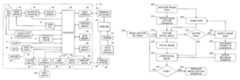
- FIG. 2is a high-level diagram showing the components of a digital camera system
- FIG. 3is a flow diagram depicting typical image processing operations used to process digital images in a digital camera
- FIG. 4is a flow chart showing a method for capturing a burst image sequence according to a preferred embodiment
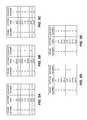
- FIGS. 5A-5Eillustrate an example showing the management of a buffer memory during the capture of a burst image sequence according to a preferred embodiment
- FIG. 6illustrates an example showing the management of a buffer memory during the capture of a burst image sequence according to an alternate embodiment
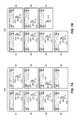
- FIG. 7Ashows an example of a burst image sequence which is terminated when a moving object exits the field of view of the digital camera
- FIG. 7Bshows an example of a burst image sequence when no motion is detected within the field of view of the digital camera
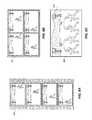
- FIGS. 8A-8Cshow examples of composite images formed using a composite burst mode in accordance with various embodiments.
- FIGS. 9A-9Bshows an example where a burst image sequence is used to form a composite panoramic image.
- the present inventionrepresents a digital camera having a variable time duration burst image capture mode.
- the burst image capture modecan be used to generate a composite image highlighting a moving object.
- This inventionprovides a method for managing buffer memory in a manner such that a user does not need to manually set image capture settings specifying a total time duration for the burst of image captures, thus reducing the number of unacceptable results.
- a computer program for performing the method of the present inventioncan be stored in a computer readable storage medium, which can include, for example; magnetic storage media such as a magnetic disk (such as a hard drive or a floppy disk) or magnetic tape; optical storage media such as an optical disc, optical tape, or machine readable bar code; solid state electronic storage devices such as random access memory (RAM), or read only memory (ROM); or any other physical device or medium employed to store a computer program having instructions for controlling one or more computers to practice the method according to the present invention.
- a computer readable storage mediumcan include, for example; magnetic storage media such as a magnetic disk (such as a hard drive or a floppy disk) or magnetic tape; optical storage media such as an optical disc, optical tape, or machine readable bar code; solid state electronic storage devices such as random access memory (RAM), or read only memory (ROM); or any other physical device or medium employed to store a computer program having instructions for controlling one or more computers to practice the method according to the present invention.
- FIG. 2depicts a block diagram of a digital photography system, including a digital camera 10 in accordance with the present invention.
- the digital camera 10is a portable battery operated device, small enough to be easily handheld by a user when capturing and reviewing images.
- the digital camera 10produces digital images that are stored as digital image files using image memory 30 .
- the phrase “digital image” or “digital image file”, as used herein,refers to any digital image file, such as a digital still image or a digital video file.
- the digital camera 10captures both motion video images and still images.
- the digital camera 10can also include other functions, including, but not limited to, the functions of a digital music player (e.g. an MP3 player), a mobile telephone, a GPS receiver, or a programmable digital assistant (PDA).
- a digital music playere.g. an MP3 player
- a mobile telephonee.g. an MP3 player
- a GPS receivere.g. a GPS receiver
- PDAprogrammable digital assistant
- the digital camera 10includes a lens 4 having an adjustable aperture and adjustable shutter 6 .
- the lens 4is a zoom lens and is controlled by zoom and focus motor drives 8 .
- the lens 4focuses light from a scene (not shown) onto an image sensor 14 , for example, a single-chip color CCD or CMOS image sensor.
- the lens 4is one type optical system for forming an image of the scene on the image sensor 14 .
- the optical systemmay use a fixed focal length lens with either variable or fixed focus.
- the output of the image sensor 14is converted to digital form by Analog Signal Processor (ASP) and Analog-to-Digital (A/D) converter 16 , and temporarily stored in buffer memory 18 .
- the buffer memory 18is adapted to store a plurality of captured digital images captured at a sequence of image capture times.
- the present inventionincludes a method to manage the storage of the captured digital images in the buffer memory 18 in order to provide a variable time duration burst capture mode.
- the image data stored in buffer memory 18is subsequently manipulated by a processor 20 , using embedded software programs (e.g. firmware) stored in firmware memory 28 .
- the software programis permanently stored in firmware memory 28 using a read only memory (ROM).
- the firmware memory 28can be modified by using, for example, Flash EPROM memory.
- an external devicecan update the software programs stored in firmware memory 28 using the wired interface 38 or the wireless modem 50 .
- the firmware memory 28can also be used to store image sensor calibration data, user setting selections and other data which must be preserved when the camera is turned off.
- the processor 20includes a program memory (not shown), and the software programs stored in the firmware memory 28 are copied into the program memory before being executed by the processor 20 .
- processor 20can be provided using a single programmable processor or by using multiple programmable processors, including one or more digital signal processor (DSP) devices.
- the processor 20can be provided by custom circuitry (e.g., by one or more custom integrated circuits (ICs) designed specifically for use in digital cameras), or by a combination of programmable processor(s) and custom circuits.
- connectors between the processor 20 from some or all of the various components shown in FIG. 2can be made using a common data bus.
- the connection between the processor 20 , the buffer memory 18 , the image memory 30 , and the firmware memory 28can be made using a common data bus.
- the image memory 30can be any form of memory known to those skilled in the art including, but not limited to, a removable Flash memory card, internal Flash memory chips, magnetic memory, or optical memory.
- the image memory 30can include both internal Flash memory chips and a standard interface to a removable Flash memory card, such as a Secure Digital (SD) card.
- SDSecure Digital
- a different memory card formatcan be used, such as a micro SD card, Compact Flash (CF) card, MultiMedia Card (MMC), xD card or Memory Stick.
- the image sensor 14is commonly controlled by a timing generator 12 , which produces various clocking signals to select rows and pixels and synchronizes the operation of the ASP and A/D converter 16 .
- the image sensor 14can have, for example, 12.4 megapixels (4088 ⁇ 3040 pixels) in order to provide a still image file of approximately 4000 ⁇ 3000 pixels.
- the image sensor 14is generally overlaid with a color filter array, which provides an image sensor having an array of pixels that include different colored pixels.
- the different color pixelscan be arranged in many different patterns. As one example, the different color pixels can be arranged using the well-known Bayer color filter array, as described in commonly assigned U.S. Pat. No.
- a motion analysis block 54is used to analyze captured digital images to characterize motion in the scene.
- the motion analysis block 54uses consecutively captured digital images to determine image motion vectors representing the velocity associated with specific image subject content.
- the motion analysis block 54can be a special purpose processor adapted to determine motion vectors between pairs of digital images.
- the motion analysis block 54can be a process executed by the processor 20 .
- the motion analysis block 54can use any method known in the art to determine the image motion vectors. In one embodiment, the method for estimating subject motion described in co-pending, commonly assigned U.S. patent application Ser. No.
- the image sensor 14 , timing generator 12 , and ASP and A/D converter 16can be separately fabricated integrated circuits, or they can be fabricated as a single integrated circuit as is commonly done with CMOS image sensors. In some embodiments, this single integrated circuit can perform some of the other functions shown in FIG. 2 , including some of the functions provided by processor 20 .
- the image sensor 14is effective when actuated in a first mode by timing generator 12 for providing a motion sequence of lower resolution sensor image data, which is used when capturing video images and also when previewing a still image to be captured, in order to compose the image.
- This preview mode sensor image datacan be provided as HD resolution image data, for example, with 1920 ⁇ 1040 pixels, or as VGA resolution image data, for example, with 640 ⁇ 480 pixels, or using other resolutions which have significantly fewer columns and rows of data, compared to the resolution of the image sensor.
- the preview mode sensor image datacan be provided by combining values of adjacent pixels having the same color, or by eliminating some of the pixels values, or by combining some color pixels values while eliminating other color pixel values.
- the preview mode image datacan be processed as described in commonly assigned U.S. Pat. No. 6,292,218 to Parulski, et al., entitled “Electronic camera for initiating capture of still images while previewing motion images,” which is incorporated herein by reference.
- the image sensor 14is also effective when actuated in a second mode by timing generator 12 for providing high resolution still image data.
- This final mode sensor image datais provided as high resolution output image data, which for scenes having a high illumination level includes all of the pixels of the image sensor, and can be, for example, a 12 megapixel final image data having 4000 ⁇ 3000 pixels.
- the final sensor image datacan be provided by “binning” some number of like-colored pixels on the image sensor 14 , in order to increase the signal level and thus the “ISO speed” of the sensor.
- the zoom and focus motor drivers 8are controlled by control signals supplied by the processor 20 , to provide the appropriate focal length setting and to focus the scene onto the image sensor 14 .
- the exposure level of the image sensor 14is controlled by controlling the F/# and exposure time of the adjustable aperture and adjustable shutter 6 , the exposure period of the image sensor 14 via the timing generator 12 , and the gain (i.e., ISO speed) setting of the ASP and A/D converter 16 .
- the processor 20also controls a flash 2 which can illuminate the scene.
- the F/# and the exposure time, as well as the flash settingare preferably determined responsive to a detected motion velocity.
- the lens 4 of the digital camera 10can be focused in the first mode by using “through-the-lens” autofocus, as described in commonly-assigned U.S. Pat. No. 5,668,597, entitled “Electronic Camera with Rapid Automatic Focus of an Image upon a Progressive Scan Image Sensor” to Parulski et al., which is incorporated herein by reference.
- Thisis accomplished by using the zoom and focus motor drivers 8 to adjust the focus position of the lens 4 to a number of positions ranging between a near focus position to an infinity focus position, while the processor 20 determines the closest focus position which provides a peak sharpness value for a central portion of the image captured by the image sensor 14 .
- the focus distance which corresponds to the closest focus positioncan then be utilized for several purposes, such as automatically setting an appropriate scene mode, and can be stored as metadata in the image file, along with other lens and camera settings.
- the processor 20produces menus and low resolution color images that are temporarily stored in display memory 36 and are displayed on the image display 32 .
- the image display 32is typically an active matrix color liquid crystal display (LCD), although other types of displays, such as organic light emitting diode (OLED) displays, can be used.
- a video interface 44provides a video output signal from the digital camera 10 to a video display 46 , such as a flat panel HDTV display.
- preview modeor video mode
- the digital image data from buffer memory 18is manipulated by processor 20 to form a series of motion preview images that are displayed, typically as color images, on the image display 32 .
- the images displayed on the image display 32are produced using the image data from the digital image files stored in image memory 30 .
- the graphical user interface displayed on the image display 32is controlled in response to user input provided by user controls 34 .
- the user controls 34are used to select various camera modes, such as video capture mode, still capture mode, burst image capture mode, and review mode, and to initiate capture of still images, recording of motion images.
- the user controls 34are also used to set user processing preferences, and to choose between various photography modes based on scene type and taking conditions.
- various camera settingsmay be set automatically in response to analysis of preview image data, audio signals, or external signals such as GPS, weather broadcasts, or other available signals.
- the above-described preview modeis initiated when the user partially depresses a shutter button, which is one of the user controls 34
- the still image capture modeis initiated when the user fully depresses the shutter button.
- the user controls 34are also used to turn on the digital camera 10 , control the lens 4 , and initiate the picture taking process.
- User controls 34typically include some combination of buttons, rocker switches, joysticks, or rotary dials.
- some of the user controls 34are provided by using a touch screen overlay on the image display 32 .
- the user controls 34can include a means to receive input from the user or an external device via a tethered, wireless, voice activated, visual or other interface.
- additional status displays or images displayscan be used.
- the camera modes that can be selected using the user controls 34include a “timer” mode.
- a short delaye.g. 10 seconds
- the digital camera 10includes an inertial sensor 9 , which can be used to sense motion of the digital camera 10 .
- the inertial sensor 9can include one or more motion sensing elements such as gyroscopes or accelerometers.
- An audio codec 22 connected to the processor 20receives an audio signal from a microphone 24 and provides an audio signal to a speaker 26 . These components can be used to record and playback an audio track, along with a video sequence or still image. If the digital camera 10 is a multi-function device such as a combination camera and mobile phone, the microphone 24 and the speaker 26 can be used for telephone conversation.
- the speaker 26can be used as part of the user interface, for example to provide various audible signals which indicate that a user control has been depressed, or that a particular mode has been selected.
- the microphone 24 , the audio codec 22 , and the processor 20can be used to provide voice recognition, so that the user can provide a user input to the processor 20 by using voice commands, rather than user controls 34 .
- the speaker 26can also be used to inform the user of an incoming phone call. This can be done using a standard ring tone stored in firmware memory 28 , or by using a custom ring-tone downloaded from a wireless network 58 and stored in the image memory 30 .
- a vibration device(not shown) can be used to provide a silent (e.g., non audible) notification of an incoming phone call.
- the processor 20also provides additional processing of the image data from the image sensor 14 , in order to produce rendered sRGB image data which is compressed and stored within a “finished” image file, such as a well-known Exif-JPEG image file, in the image memory 30 .
- a “finished” image filesuch as a well-known Exif-JPEG image file
- the digital camera 10can be connected via the wired interface 38 to an interface/recharger 48 , which is connected to a computer 40 , which can be a desktop computer or portable computer located in a home or office.
- the wired interface 38can conform to, for example, the well-known USB 2.0 interface specification.
- the interface/recharger 48can provide power via the wired interface 38 to a set of rechargeable batteries (not shown) in the digital camera 10 .
- the digital camera 10can include a wireless modem 50 , which interfaces over a radio frequency band 52 with the wireless network 58 .
- the wireless modem 50can use various wireless interface protocols, such as the well-known Bluetooth wireless interface or the well-known 802.11 wireless interface.
- the computer 40can upload images via the Internet 70 to a photo service provider 72 , such as the Kodak EasyShare Gallery. Other devices (not shown) can access the images stored by the photo service provider 72 .
- the wireless modem 50communicates over a radio frequency (e.g. wireless) link with a mobile phone network (not shown), such as a 3GSM network, which connects with the Internet 70 in order to upload digital image files from the digital camera 10 .
- a radio frequencye.g. wireless
- a mobile phone networknot shown
- 3GSM networkwhich connects with the Internet 70 in order to upload digital image files from the digital camera 10 .
- These digital image filescan be provided to the computer 40 or the photo service provider 72 .
- FIG. 3is a flow diagram depicting image processing operations that can be performed by the processor 20 in the digital camera 10 ( FIG. 2 ) in order to process color sensor data 100 from the image sensor 14 output by the ASP and A/D converter 16 .
- the processing parameters used by the processor 20 to manipulate the color sensor data 100 for a particular digital imageare determined by various photography mode settings 175 , which are typically associated with photography modes that can be selected via the user controls 34 , which enable the user to adjust various camera settings 185 in response to menus displayed on the image display 32 .
- the color sensor data 100 which has been digitally converted by the ASP and A/D converter 16is manipulated by a white balance step 95 .
- this processingcan be performed using the methods described in commonly-assigned U.S. Pat. No. 7,542,077 to Miki, entitled “White balance adjustment device and color identification device”, the disclosure of which is herein incorporated by reference.
- the white balancecan be adjusted in response to a white balance setting 90 , which can be manually set by a user, or which can be automatically set by the digital camera 10 .
- the color image datais then manipulated by a noise reduction step 105 in order to reduce noise from the image sensor 14 .
- this processingcan be performed using the methods described in commonly-assigned U.S. Pat. No. 6,934,056 to Gindele et al., entitled “Noise cleaning and interpolating sparsely populated color digital image using a variable noise cleaning kernel,” the disclosure of which is herein incorporated by reference.
- the level of noise reductioncan be adjusted in response to the ISO setting 110 , so that more filtering is performed at higher ISO setting.
- the color image datais then manipulated by a demosaicing step 115 , in order to provide red, green and blue (RGB) image data values at each pixel location.
- Algorithms for performing the demosaicing step 115are commonly known as color filter array (CFA) interpolation algorithms or “deBayering” algorithms.
- CFAcolor filter array
- the demosaicing step 115can use the luminance CFA interpolation method described in commonly-assigned U.S. Pat. No. 5,652,621, entitled “Adaptive color plane interpolation in single sensor color electronic camera,” to Adams et al., the disclosure of which is incorporated herein by reference.
- the demosaicing step 115can also use the chrominance CFA interpolation method described in commonly-assigned U.S. Pat. No. 4,642,678, entitled “Signal processing method and apparatus for producing interpolated chrominance values in a sampled color image signal”, to Cok, the disclosure of which is herein incorporated by reference.
- the usercan select between different pixel resolution modes, so that the digital camera 10 can produce a smaller size image file.
- Multiple pixel resolutionscan be provided as described in commonly-assigned U.S. Pat. No. 5,493,335, entitled “Single sensor color camera with user selectable image record size,” to Parulski et al., the disclosure of which is herein incorporated by reference.
- a resolution mode setting 120can be selected by the user to be full size (e.g. 4,000 ⁇ 3,000 pixels), medium size (e.g. 2,000 ⁇ 1,500 pixels) or small size (750 ⁇ 500 pixels).
- the color image datais color corrected in color correction step 125 .
- the color correctionis provided using a 3 ⁇ 3 linear space color correction matrix, as described in commonly-assigned U.S. Pat. No. 5,189,511, entitled “Method and apparatus for improving the color rendition of hardcopy images from electronic cameras” to Parulski, et al., the disclosure of which is incorporated herein by reference.
- different user-selectable color modescan be provided by storing different color matrix coefficients in firmware memory 28 of the digital camera 10 . For example, four different color modes can be provided, so that the color mode setting 130 is used to select one of the following color correction matrices:
- a three-dimensional lookup tablecan be used to perform the color correction step 125 .
- the color image datais also manipulated by a tone scale correction step 135 .
- the tone scale correction step 135can be performed using a one-dimensional look-up table as described in U.S. Pat. No. 5,189,511, cited earlier.
- a plurality of tone scale correction look-up tablesis stored in the firmware memory 28 in the digital camera 10 . These can include look-up tables which provide a “normal” tone scale correction curve, a “high contrast” tone scale correction curve, and a “low contrast” tone scale correction curve.
- a user selected contrast setting 140is used by the processor 20 to determine which of the tone scale correction look-up tables to use when performing the tone scale correction step 135 .
- a burst image compositing step 195can optionally be used to form a composite image according to composite settings 190 .
- This stepis shown with a dashed outline reflecting the fact that it is an optional step that is only applied when the user has set the user controls 34 of the digital camera 10 to form a composite image using the burst image capture mode.
- specific image scene components within each digital imageare combined to form the composite image.
- an image backgroundis formed using image content from one or more of the digital images.
- subject image regions corresponding to one or more objects that had transitioned across the image backgroundare extracted from the selected digital images and merged onto the image background. Additional details regarding the capturing of a set of digital images that can be used for the burst image compositing step 195 will be described later.
- the color image datais also manipulated by an image sharpening step 145 .
- thiscan be provided using the methods described in commonly-assigned U.S. Pat. No. 6,192,162 entitled “Edge enhancing colored digital images” to Hamilton, et al., the disclosure of which is incorporated herein by reference.
- the usercan select between various sharpening settings, including a “normal sharpness” setting, a “high sharpness” setting, and a “low sharpness” setting.
- the processor 20uses one of three different edge boost multiplier values, for example 2.0 for “high sharpness”, 1.0 for “normal sharpness”, and 0.5 for “low sharpness” levels, responsive to a sharpening setting 150 selected by the user of the digital camera 10 .
- the color image datais also manipulated by an image compression step 155 .
- the image compression step 155can be provided using the methods described in commonly-assigned U.S. Pat. No. 4,774,574, entitled “Adaptive block transform image coding method and apparatus” to Daly et al., the disclosure of which is incorporated herein by reference.
- the usercan select between various compression settings. This can be implemented by storing a plurality of quantization tables, for example, three different tables, in the firmware memory 28 of the digital camera 10 . These tables provide different quality levels and average file sizes for the compressed digital image file 180 to be stored in the image memory 30 of the digital camera 10 .
- a user selected compression mode setting 160is used by the processor 20 to select the particular quantization table to be used for the image compression step 155 for a particular image.
- the compressed color image datais stored in a digital image file 180 using a file formatting step 165 .
- the image filecan include various metadata 170 .
- Metadata 170is any type of information that relates to the digital image, such as the model of the camera that captured the image, the size of the image, the date and time the image was captured, and various camera settings, such as the lens focal length, the exposure time and f-number of the lens, and whether or not the camera flash fired.
- all of this metadata 170is stored using standardized tags within the well-known Exif-JPEG still image file format.
- the metadata 170includes information about various camera settings 185 , including the photography mode settings 175 .
- the image sensor 14When the digital camera 10 is operated in a burst image capture mode, the image sensor 14 is actuated by the timing generator 12 to fill the buffer memory 18 with a set of captured digital images. In some embodiments, the set of captured digital images is then used to form a composite image using the burst image compositing step 195 .
- a variable time duration burst image capture modeis provided by dynamically adjusting the usage of the buffer memory 18 ( FIG. 1 ), together with a frame rate 205 . Accordingly, a burst image sequence can be captured having an unknown time duration even though the buffer memory 18 has a capacity to store a finite number of digital images.
- the initial frame ratewill be the fastest frame rate at which the digital camera 10 ( FIG. 2 ) is able to capture sequential digital images.
- the initial frame ratecan be some other predefined frame rate, or can alternately be selected using appropriate user controls 34 ( FIG. 2 ).
- the frame rate 205can be specified using any appropriate units such as “frames/second.” Since there is a defined relationship between the frame rate 205 and the corresponding image capture time interval ⁇ T, it will be recognized that the frame rate can equivalently be specified by designating the image capture time interval ⁇ T in appropriate time units (e.g., seconds, or number of clock cycles between successive image captures).
- appropriate time unitse.g., seconds, or number of clock cycles between successive image captures.
- An initiate image capture sequence step 210is used to initiate the capture of a sequence (i.e., a “burst”) of digital images.
- the initiate image capture sequence step 210is triggered by the activation of an image capture control such as a shutter button when the digital camera 10 is set to operate in the burst capture mode.
- the initiate image capture sequence step 210can be triggered by other means.
- a timercan be used to delay the initiation of the image capture sequence for a defined time delay after the image capture control has been activated.
- a stream of preview imagescan be analyzed and the initiate image capture sequence step 210 can be triggered when a moving object is detected in the scene. In this way, the photographer can be included as a subject in the burst image sequence by setting the digital camera 10 on a tripod and having the initiate image capture sequence step 210 execute automatically when the photographer enters the field of view of the digital camera 10 .
- a capture digital image step 215is then used to capture a digital image 225 according to specified image capture settings 220 .
- the image capture settings 225would include various settings such as an exposure time setting, a lens aperture setting, an ISO setting or an image resolution setting.
- the captured digital image 225is to be stored in buffer memory 18 ( FIG. 2 ).
- the buffer memory 18will only be able to store a finite number of captured digital images 225 . Therefore, depending on the time duration of the burst image sequence, the buffer memory 18 may become filled.
- a buffer full test 230is used to determine whether the buffer memory 18 has been filled to a predetermined capacity.
- the predetermined capacitycorresponds to there not being enough room to store any additional digital images 225 in the buffer memory 18 .
- the buffer memory 18may have capacity to store eight images. In this case, if the buffer memory 18 has eight images stored in it, the buffer full test 230 would indicate that the buffer memory 18 is full.
- a store digital image step 235is used to store the captured digital image 225 in the next available location in the buffer memory 18 .
- a series of stepsare used to free up some of the buffer memory 18 so that the time duration of the burst image sequence can be extended.
- the buffer memory 18is freed up by designating a set of stored digital images that can be overwritten rather than by actually deleting anything from the buffer memory.
- a modify frame rate step 240is used to modify the frame rate 205 .
- the new frame ratecan be reduced by some other integer multiple besides two (e.g., it can be reduced by a factor of 3 ⁇ or 4 ⁇ ).
- the frame rate 205can even be reduced by a non-integer factor.
- the stored digital imagesmay not contain frames having capture times that correspond exactly to the new frame rate 205 .
- a designate frames to overwrite step 245is used to designate a set of the previously stored digital images that are stored in the buffer memory 18 ( FIG. 2 ) that can be overwritten. The remaining stored digital images are designated to be retained. In a preferred embodiment, any stored digital images having image capture times not corresponding to the new frame rate 205 are designated as stored digital images that can be overwritten.
- every other digital image in the burst image capture sequencei.e., either the even-numbered digital images or the odd-numbered digital images
- every other digital image in the burst image capture sequencecan be designated to be overwritten
- the stored digital images that are designated to be overwrittencan be deleted from the buffer memory 18 , but generally it will be preferable to simply overwrite the old image data with new image data as new images are captured.
- An optional update sequence numbers step 250is then used to renumber the digital images that are not designated to be overwritten. Execution then proceeds to the store digital image step 235 . If the current digital image 225 is designated to be retained, it is stored using the store digital image step 235 . Otherwise, this step is skipped and execution can proceed to done test 255 .
- FIGS. 5A-5EAn example showing management of the buffer memory 18 ( FIG. 2 ) during the capture of a burst image sequence is illustrated in FIGS. 5A-5E .
- the buffer memory 18can store eight digital images in corresponding buffer memory areas that will be referred to as frames # 1 -# 8 .
- a first set of eight digital imagesare captured using an image capture time interval of ⁇ T and are stored in corresponding frames of the buffer memory 18 .
- the buffer full test 230determines that the buffer memory 18 has been filled to capacity.
- the modify frame rate step 240updates the frame rate 205 ( FIG. 4 ) by reducing it by a factor of two.
- the new image capture time intervalwill therefore be 2 ⁇ T.
- the designate frames to overwrite step 245designates any stored digital images that were not captured at image captured times corresponding to the new frame rate 205 ( FIG. 4 ) to be overwritten.
- frames # 1 , # 3 , # 5 and # 7were captured at image capture times that are consistent with the new frame rate 205 , and they are therefore designated to be kept.
- frames # 2 , # 4 , # 5 and # 8were captured at image capture times that are not consistent with the new frame rate 205 , and they are therefore designated to be overwritten.
- the update sequence numbers step 250( FIG. 4 ) is then used to renumber the frames that are to be kept.
- FIG. 5Bshows the status of the buffer memory 18 following these operations. The frames that are available to be overwritten are designated as being “open” in this figure.
- FIG. 5Cshows the status of the buffer memory 18 after four more digital images have been captured and stored. It can be seen that frame # 2 of the buffer memory now contains a digital image 225 ( FIG. 4 ) captured at an image capture time of 8 ⁇ T, having a corresponding image sequence # 5 . Likewise, frames # 4 , # 6 and # 8 contain digital images 225 that were captured at image capture times of 10 ⁇ T, 12 ⁇ T and 14 ⁇ T, respectively. Note that the designated frames can be overwritten in different orders in various embodiments. For example, in some embodiments, the first frame that is overwritten is the most recently captured of the frames that were designated to be overwritten.
- the buffer full test 230( FIG. 4 ) again determines that the buffer memory 18 has been filled to capacity.
- the modify frame rate step 240( FIG. 4 ) then updates the frame rate 205 ( FIG. 4 ) by again reducing it by another factor of two.
- the new image capture time intervalwill therefore be 4 ⁇ T.
- the designate frames to overwrite step 245designates any stored digital images that were not captured at image captured times corresponding to the new frame rate 205 ( FIG. 4 ) to be overwritten.
- frames # 1 , # 2 , # 5 and # 6were captured at image capture times that are consistent with the new frame rate 205 , and they are therefore designated to be kept.
- frames # 3 , # 4 , # 7 and # 8were captured at image capture times that are not consistent with the new frame rate 205 , and they are therefore designated to be overwritten.
- the update sequence numbers step 250( FIG. 4 ) is then used to renumber the frames that are to be kept.
- FIG. 5Dshows the status of the buffer memory 18 following these operations.
- FIG. 5Eshows the status of the buffer memory 18 after four more digital images have been captured and stored. It can be seen that frame # 3 of the buffer memory now contains a digital image 225 ( FIG. 4 ) captured at an image capture time of 16 ⁇ T, having a corresponding image sequence # 5 . Likewise, frames # 4 , # 7 and # 8 contain digital images 225 that were captured at image capture times of 20 ⁇ T, 24 ⁇ T and 28 ⁇ T, respectively. This process will continue indefinitely until the burst image capture sequence is terminated.
- the predetermined capacity considered by the buffer full test 230corresponds to less than a totally full buffer memory 18 ( FIG. 2 ).
- the buffer full test 230can check to see whether the buffer memory 18 has reached half of its maximum capacity. If so, the buffer memory 18 is designated to have been filled to the predetermined capacity.
- the modify frame rate step 240is then used to determine a new reduced frame rate 205 as described earlier. However, in this case, it is not necessary to mark any frames for deletion since there is still additional capacity in the buffer memory 18 . Rather, additional digital images 225 can continue to be captured and stored in the buffer memory 18 according to the new frame rate 205 .
- the predetermined capacitycan then be adjusted so that the buffer full test 230 will now compare the fullness of the buffer memory 18 to a new predetermined capacity (e.g., 3 ⁇ 4 of the maximum capacity). If the digital images stored in the buffer memory 18 is then determined to exceed the new predetermined capacity, the frame rate 205 can be reduced even further. In this case, the individual digital images in the burst image capture sequence will not be spaced by a uniform time interval.
- a new predetermined capacitye.g., 3 ⁇ 4 of the maximum capacity
- FIG. 6An example showing management of the buffer memory 18 ( FIG. 2 ) during the capture of a burst image sequence using this approach is illustrated in FIG. 6 .
- four digital imagesare captured using an initial frame rate 205 ( FIG. 4 ) having a corresponding image capture time interval of ⁇ T.
- the buffer memory 18is determined to have been filled to the predetermined capacity (50%) and the frame rate 205 is adjusted so that additional digital images are captured using an image capture time interval of 2 ⁇ T.
- a new predetermined capacity of 75%is then assigned for use with the buffer full test 230 ( FIG. 4 ).
- the image frames numbered # 5 and # 6are then captured using the new frame rate 205 .
- the buffer memory 18is determined to have been filled to the new predetermined capacity (75%) and the frame rate 205 is adjusted again so that additional digital images are captured using an image capture time interval of 4 ⁇ T.
- a new predetermined capacity of 100%is then assigned for use with the buffer full test 230 .
- the image frames numbered # 7 and # 8are then captured using the new frame rate 205 .
- the buffer full test 230determines that the buffer memory 18 is full to 100% of its capacity. Since there is no room to store additional digital images, either the burst image capture sequence can be terminated, or some of the stored digital images can be designated to be overwritten as was described earlier.
- a done test 255is used to determine whether the burst image capture sequence should be terminated.
- the done test 255can use a variety of different methods to determine whether or not the burst image capture sequence should be terminated.
- the burst image capture sequenceis initiated when the user presses an image capture button on the digital camera 10 , and is terminated when the user releases the image capture button.
- the done test 255checks the status of the image capture button, and if the image capture button is still depressed, execution returns to the capture digital image step 215 where the next digital image 225 is captured at an image capture time determined according to the frame rate 205 . If the image capture button has been released, the done test 255 passes control to a terminate image capture sequence step 260 .
- the terminate image capture sequence step 260terminates the capture of any additional digital images, and will generally initiate processing of the digital images stored in the buffer memory 18 according to the processing steps described earlier with respect to FIG. 3 .
- each of the processed digital images in the burst image capture sequenceis stored in a separate digital image file in the image memory 30 ( FIG. 2 ).
- the processed digital imagescan be stored in JPG files using the well-known EXIF digital image file format.
- the individual digital imagescan be combined to form a composite image, or stored in some other fashion.
- the done test 255can use other methods to determine whether or not the burst image capture sequence should be terminated. For example, in some embodiments a maximum time duration for the burst image capture sequence is specified. If the maximum time duration has been reached, the burst image capture sequence is terminated even if the user has not released the image capture control. This provides a “backup” method for terminating the burst image capture sequence if the time duration is extended beyond a reasonable length.
- the digital camera 10includes motion analysis block 54 which can be used to analyze captured digital images to characterize motion in the scene, for example by determining a rate of motion for at least one moving object in the scene.
- the rate of motionis an image motion vector giving a direction and a magnitude of the object motion.
- the motion analysis block 54can use any method known in the art to determine the rate of motion, such as the method for estimating subject motion described in the aforementioned U.S. patent application Ser. No. 13/021,067, entitled “Estimating subject motion between image frames.”
- the motion analysis block 54determines the position of the moving object in each captured digital image rather than the rate of motion. If desired, a rate of motion can subsequently be determined based on a difference between the position of the moving object in successive digital images.
- the motion analysis block 54determines the rate of motion for a moving foreground object in the scene.
- the motion analysis block 54may detect a plurality of moving foreground objects in the scene.
- a number of different strategiescan be used to determine the rate of motion.
- the rate of motioncan be determined for the fastest moving object, or the moving object nearest to the center of the frame.
- the rates of motion for the plurality of moving foreground objectscan be combined to determine a combined rate of motion.
- a weighted average of the magnitudes of the rates of motioncan be computed.
- the weights used for the weighted averagecan be determined in a variety of ways. For example, they can be a function of the size or the position of the moving objects.
- a main subject detection algorithmcan be used to identify a main subject in the scene. If the main subject corresponds to one of the moving objects, the rate of motion can then be determined based on the main subject. Any method for detecting the main subject known in the art can be used to identify the main subject.
- Main subject detection algorithmsare well-known in the art.
- One example of a main subject detection algorithm that can be used in accordance with the present inventionis described in U.S. Pat. No. 6,282,317 to Luo et al., entitled “Method for automatic determination of main subjects in photographic images,” which is incorporated herein by reference.
- the determined motion characteristics for the scenecan be used by the done test 255 ( FIG. 4 ) to terminate the burst image capture sequence in some embodiments.
- the done test 255can terminate the image capture sequence when the moving the foreground object exits a field of view of the camera. Once the moving object is no longer contained in the captured digital images, it can be assumed that there is no longer any value in extending the burst image capture sequence.
- FIG. 7Aillustrates an example of this scenario.
- a digital image sequence 300is captured having eight digital images (labeled # 1 -# 8 ).
- the scenecontains a moving foreground object 305 .
- the motion analysis block 54determines a position of the moving foreground object 305 , as well as a corresponding rate of motion 310 for each successive digital image.
- the motion analysis block 54determines that the moving foreground object 305 has exited the field of view of the camera and the burst image capture sequence is accordingly terminated.
- only the digital images that contain the moving foreground object 305e.g., digital images # 1 -# 7
- digital image # 8can be retained as well.
- the done test 255can terminate the image capture sequence when the motion analysis block 54 detects no substantial object motion. This would correspond to the case where the moving foreground objects have either stopped moving or have exited the image frame. A foreground object can be determined to have stopped moving if its rate of motion falls below some specified threshold value. Once the object motion has ceased, it can be assumed that there is no longer any value in extending the burst image capture sequence.
- FIG. 7Billustrates an example of this scenario.
- a digital image sequence 320is captured having seven digital images (labeled # 1 -# 7 ).
- the scenecontains a moving foreground object 305 .
- the motion analysis block 54determines a position of the moving foreground object 305 , as well as a corresponding rate of motion 310 for each successive digital image.
- the motion analysis block 54determines that the moving foreground object 305 has stopped moving and the burst image capture sequence is accordingly terminated.
- only the digital images where the moving foreground object 305 is movinge.g., digital images # 1 -# 6
- digital image # 7can be retained as well.
- the burst image compositing step 195can be used to form a composite image from the set of captured digital images in the burst image capture sequence.
- the composite imagecan be formed using any method known in the art.
- the composite imageis a montage image formed by inserting some or all of the digital images in the burst image capture sequence into a template so that they can be viewed together.
- FIG. 8Ashows an example of a montage composite image 490 using a “film strip” template for a burst image capture sequence containing four digital images.
- FIG. 8Bshows an example of a montage composite image 492 using a 2 ⁇ 2 rectangular template.
- the composite imageis formed by extracting the moving object from each of the digital images in the burst image capture sequence and combining them onto a common background image. In one embodiment this can be done as described in commonly-assigned U.S. Pat. No. 7,024,054 “Method and system for generating a foreground mask for a composite image” to Cahill, et al., which is incorporated herein by reference.
- Other methods for identifying the boundaries of the moving object and extracting the moving object from the digital imageare well-known in the art. Such methods typically work by aligning the backgrounds in the digital images, then computing differences between the aligned sequential digital images to identify the regions where there was movement.
- the background from one of the digital images in the burst image capture sequencecan be used as the common background image.
- the backgrounds from a plurality of the digital imagescan be combined (e.g., by averaging them to remove noise) to form the common background image.
- FIG. 8Cshows an example of a composite image 494 of this type where a moving object 496 is extracted from a plurality of digital images and combined with a common background image 498 .
- the burst image capture modeis used to capture a burst image capture sequence while holding the digital camera 10 in a stationary position to capture a sequence of digital images of a scene containing a moving object on a stationary background.
- the burst image capture modecan be used to capture a sequence of digital images for a stationary scene while panning the digital camera 10 to capture a series of different fields of view.
- the digital images in the stored sequence of digital imagescan be combined to form a composite image corresponding to a panoramic image of the scene.
- FIG. 9Ashows an example where a burst image capture sequence is captured of a scene 500 using to the method of the present invention.
- the digital camera 10is operated in a burst image capture mode and is panned across the scene 500 while holding down the image capture button.
- the buffer memory 18FIG. 2
- the frame rate 205is modified using the modify frame rate step and some of the stored digital images are designated that can be overwritten using the designate frames to overwrite step 245 .
- the final burst image capture sequencecontains four digital images 505 having overlapping fields of view.
- FIG. 9Bshows an example of a composite panoramic image 510 formed by combining the four digital images 505 from FIG. 9A .
- Methods for combining a plurality of digital images 505 to form a composite panoramic image 510are well-known in the art. Most methods involve aligning the individual digital images 505 by analyzing the overlapping portions of the digital images. The composite panoramic image 510 is then formed by using appropriate portions of each of the individual digital images 505 . In the image regions where two (or more) of the individual digital images 505 overlap, a weighted average of the corresponding pixel values for the individual digital images 505 can be used to determine the pixel values for the composite panoramic image 510 . Typically, weights for the weighted average are tapered across the overlap region to provide a smooth transition between the individual digital images 505 .
- the stored sequence of digital images in the burst image capture sequencecan be combined to form a video sequence having a temporal sequence of image frames.
- the video sequencecan be useful to provide an impression of the motion in the scene.
- the video sequencecan be stored using any video file format known in the art such as the well-known MPEG 2, MPEG 4 or motion JPEG video file formats.
- each of the individual digital images in the burst image capture sequenceis repeated for a predetermined number of image frames.
- the number of repeated image frameswill determine the apparent rate of motion of the moving objects.
- the number of repeated image framescan be selected to provide realistic apparent rate of motion. For example, if the final frame rate 205 ( FIG. 4 ) for the burst image capture sequence is 5 frames/second, and if the video sequence is intended to be played at 30 frames/second, then each of the individual digital images can be repeated six times to provide a realistic apparent rate of motion.
- the apparent rate of motioncan be increased or decreased by adjusting the number of repeated image frames accordingly.
- a transitioncan be provided between the individual image frames rather than abruptly transitioning from one to the other. For example, a cross fade transition can be used so that the individual frames appear to smoothly fade from one to the other.
- a computer program productcan include one or more storage medium, for example; magnetic storage media such as magnetic disk (such as a floppy disk) or magnetic tape; optical storage media such as optical disk, optical tape, or machine readable bar code; solid-state electronic storage devices such as random access memory (RAM), or read-only memory (ROM); or any other physical device or media employed to store a computer program having instructions for controlling one or more computers to practice the method according to the present invention.
- magnetic storage mediasuch as magnetic disk (such as a floppy disk) or magnetic tape
- optical storage mediasuch as optical disk, optical tape, or machine readable bar code
- solid-state electronic storage devicessuch as random access memory (RAM), or read-only memory (ROM); or any other physical device or media employed to store a computer program having instructions for controlling one or more computers to practice the method according to the present invention.
Landscapes
- Engineering & Computer Science (AREA)
- Multimedia (AREA)
- Signal Processing (AREA)
- Studio Devices (AREA)
Abstract
Description
- an image sensor for capturing a digital image;
- an optical system for forming an image of a scene onto the image sensor;
- a data processing system;
- a frame buffer memory for temporarily storing captured digital images; and
- a program memory communicatively connected to the data processing system and storing instructions configured to cause the data processing system to implement a method for capturing a sequence of digital images in the variable time duration burst capture mode, wherein the instructions include:
- specifying a first frame rate;
- initiating an image capture sequence;
- storing a sequence of digital images captured at the first frame rate in the frame buffer memory;
- determining whether the frame buffer memory has been filled to a predetermined capacity, and if so:
- specifying a second frame rate, wherein the second frame rate is lower than the first frame rate;
- designating a set of stored digital images that can be overwritten; and
- storing a sequence of digital images captured at the second frame rate in the frame buffer memory, overwriting the designated set of stored digital images.
- 2 flash
- 4 lens
- 6 adjustable aperture and adjustable shutter
- 8 zoom and focus motor drives
- 9 inertial sensor
- 10 digital camera
- 12 timing generator
- 14 image sensor
- 16 ASP and A/D Converter
- 18 buffer memory
- 20 processor
- 22 audio codec
- 24 microphone
- 25 pressure sensor
- 26 speaker
- 28 firmware memory
- 30 image memory
- 32 image display
- 34 user controls
- 36 display memory
- 38 wired interface
- 40 computer
- 42 tilt sensor
- 44 video interface
- 46 video display
- 48 interface/recharger
- 50 wireless modem
- 52 radio frequency band
- 54 motion analysis block
- 58 wireless network
- 70 Internet
- 72 photo service provider
- 90 white balance setting
- 95 white balance step
- 100 color sensor data
- 105 noise reduction step
- 110 ISO setting
- 115 demosaicing step
- 120 resolution mode setting
- 125 color correction step
- 130 color mode setting
- 135 tone scale correction step
- 140 contrast setting
- 145 image sharpening step
- 150 sharpening setting
- 155 image compression step
- 160 compression mode setting
- 165 file formatting step
- 170 metadata
- 175 photography mode settings
- 180 digital image file
- 185 camera settings
- 190 composite settings
- 195 burst image compositing step
- 200 initialize frame rate step
- 205 frame rate
- 210 initiate image capture sequence step
- 215 capture digital image step
- 220 image capture settings
- 225 digital image
- 230 buffer full test
- 235 store digital image step
- 240 modify frame rate step
- 245 designate frames to overwrite step
- 250 update sequence numbers step
- 255 done test
- 260 terminate image capture sequence step
- 300 digital image sequence
- 305 moving foreground object
- 310 rate of motion
- 320 digital image sequence
- 490 montage composite image
- 492 montage composite image
- 494 composite image
- 496 moving object
- 498 background image
- 500 scene
- 505 digital image
- 510 composite panoramic image
Claims (19)
Priority Applications (3)
| Application Number | Priority Date | Filing Date | Title |
|---|---|---|---|
| US13/080,734US8736716B2 (en) | 2011-04-06 | 2011-04-06 | Digital camera having variable duration burst mode |
| PCT/US2012/031931WO2012138620A2 (en) | 2011-04-06 | 2012-04-03 | Digital camera having variable duration burst mode |
| TW101112109ATWI538505B (en) | 2011-04-06 | 2012-04-05 | Digital camera with variable period burst mode |
Applications Claiming Priority (1)
| Application Number | Priority Date | Filing Date | Title |
|---|---|---|---|
| US13/080,734US8736716B2 (en) | 2011-04-06 | 2011-04-06 | Digital camera having variable duration burst mode |
Publications (2)
| Publication Number | Publication Date |
|---|---|
| US20120257071A1 US20120257071A1 (en) | 2012-10-11 |
| US8736716B2true US8736716B2 (en) | 2014-05-27 |
Family
ID=45931066
Family Applications (1)
| Application Number | Title | Priority Date | Filing Date |
|---|---|---|---|
| US13/080,734Active2032-09-24US8736716B2 (en) | 2011-04-06 | 2011-04-06 | Digital camera having variable duration burst mode |
Country Status (3)
| Country | Link |
|---|---|
| US (1) | US8736716B2 (en) |
| TW (1) | TWI538505B (en) |
| WO (1) | WO2012138620A2 (en) |
Cited By (23)
| Publication number | Priority date | Publication date | Assignee | Title |
|---|---|---|---|---|
| US9307112B2 (en) | 2013-05-31 | 2016-04-05 | Apple Inc. | Identifying dominant and non-dominant images in a burst mode capture |
| US9479694B2 (en)* | 2014-10-28 | 2016-10-25 | Google Inc. | Systems and methods for autonomously generating photo summaries |
| US9973647B2 (en) | 2016-06-17 | 2018-05-15 | Microsoft Technology Licensing, Llc. | Suggesting image files for deletion based on image file parameters |
| US10049247B2 (en) | 2016-10-12 | 2018-08-14 | Datalogic Usa, Inc. | Optimization of image frame management in a sweep-style optical code data reader |
| US10205791B2 (en) | 2014-12-11 | 2019-02-12 | DialApp, Inc. | Method and system for speed and directional control of responsive frame or asset |
| US10645294B1 (en) | 2019-05-06 | 2020-05-05 | Apple Inc. | User interfaces for capturing and managing visual media |
| US11054973B1 (en) | 2020-06-01 | 2021-07-06 | Apple Inc. | User interfaces for managing media |
| US11102414B2 (en) | 2015-04-23 | 2021-08-24 | Apple Inc. | Digital viewfinder user interface for multiple cameras |
| US11112964B2 (en) | 2018-02-09 | 2021-09-07 | Apple Inc. | Media capture lock affordance for graphical user interface |
| US11128792B2 (en) | 2018-09-28 | 2021-09-21 | Apple Inc. | Capturing and displaying images with multiple focal planes |
| US11165949B2 (en) | 2016-06-12 | 2021-11-02 | Apple Inc. | User interface for capturing photos with different camera magnifications |
| US11178335B2 (en) | 2018-05-07 | 2021-11-16 | Apple Inc. | Creative camera |
| US11204692B2 (en) | 2017-06-04 | 2021-12-21 | Apple Inc. | User interface camera effects |
| US11212449B1 (en) | 2020-09-25 | 2021-12-28 | Apple Inc. | User interfaces for media capture and management |
| US11321857B2 (en) | 2018-09-28 | 2022-05-03 | Apple Inc. | Displaying and editing images with depth information |
| US11350026B1 (en) | 2021-04-30 | 2022-05-31 | Apple Inc. | User interfaces for altering visual media |
| US11468625B2 (en) | 2018-09-11 | 2022-10-11 | Apple Inc. | User interfaces for simulated depth effects |
| US11706521B2 (en) | 2019-05-06 | 2023-07-18 | Apple Inc. | User interfaces for capturing and managing visual media |
| US11722764B2 (en) | 2018-05-07 | 2023-08-08 | Apple Inc. | Creative camera |
| US11770601B2 (en) | 2019-05-06 | 2023-09-26 | Apple Inc. | User interfaces for capturing and managing visual media |
| US11778339B2 (en) | 2021-04-30 | 2023-10-03 | Apple Inc. | User interfaces for altering visual media |
| US12112024B2 (en) | 2021-06-01 | 2024-10-08 | Apple Inc. | User interfaces for managing media styles |
| US12401889B2 (en) | 2023-05-05 | 2025-08-26 | Apple Inc. | User interfaces for controlling media capture settings |
Families Citing this family (85)
| Publication number | Priority date | Publication date | Assignee | Title |
|---|---|---|---|---|
| KR20110052124A (en)* | 2009-11-12 | 2011-05-18 | 삼성전자주식회사 | Panorama image generation and inquiry method and mobile terminal using the same |
| JP5704957B2 (en)* | 2011-02-22 | 2015-04-22 | キヤノン株式会社 | Movie shooting apparatus and control method thereof |
| US9417754B2 (en) | 2011-08-05 | 2016-08-16 | P4tents1, LLC | User interface system, method, and computer program product |
| JP5803467B2 (en)* | 2011-09-14 | 2015-11-04 | 株式会社リコー | Image processing apparatus, imaging apparatus, and image processing method |
| KR101805626B1 (en)* | 2011-11-18 | 2017-12-08 | 삼성전자주식회사 | Digital photographing apparatus and continuous photographing method thereof |
| US20130176458A1 (en)* | 2012-01-11 | 2013-07-11 | Edwin Van Dalen | Flexible Burst Image Capture System |
| JP5613187B2 (en)* | 2012-01-27 | 2014-10-22 | オリンパスイメージング株式会社 | IMAGING DEVICE, IMAGING DEVICE CONTROL METHOD, AND SUSTAINABLE COMPUTER-READABLE MEDIUM CONTAINING CODE FOR CAUSING COMPUTER TO CONTROL IMAGING DEVICE |
| EP2819398A4 (en)* | 2012-02-20 | 2015-10-28 | Sony Corp | IMAGE PROCESSING DEVICE, IMAGE PROCESSING AND PROGRAM |
| TWI528163B (en)* | 2012-04-25 | 2016-04-01 | 鴻海精密工業股份有限公司 | Power saving surveillance system and method |
| KR101899851B1 (en)* | 2012-05-03 | 2018-09-18 | 삼성전자 주식회사 | Apparatus and mehod for processing a image in camera device |
| WO2013169851A2 (en) | 2012-05-09 | 2013-11-14 | Yknots Industries Llc | Device, method, and graphical user interface for facilitating user interaction with controls in a user interface |
| WO2013169849A2 (en) | 2012-05-09 | 2013-11-14 | Industries Llc Yknots | Device, method, and graphical user interface for displaying user interface objects corresponding to an application |
| WO2013169845A1 (en) | 2012-05-09 | 2013-11-14 | Yknots Industries Llc | Device, method, and graphical user interface for scrolling nested regions |
| CN108958550B (en) | 2012-05-09 | 2021-11-12 | 苹果公司 | Device, method and graphical user interface for displaying additional information in response to user contact |
| WO2013169875A2 (en) | 2012-05-09 | 2013-11-14 | Yknots Industries Llc | Device, method, and graphical user interface for displaying content associated with a corresponding affordance |
| AU2013259630B2 (en) | 2012-05-09 | 2016-07-07 | Apple Inc. | Device, method, and graphical user interface for transitioning between display states in response to gesture |
| HK1208275A1 (en) | 2012-05-09 | 2016-02-26 | 苹果公司 | Device, method, and graphical user interface for moving and dropping a user interface object |
| WO2013169843A1 (en) | 2012-05-09 | 2013-11-14 | Yknots Industries Llc | Device, method, and graphical user interface for manipulating framed graphical objects |
| CN108241465B (en) | 2012-05-09 | 2021-03-09 | 苹果公司 | Method and apparatus for providing haptic feedback for operations performed in a user interface |
| EP2847662B1 (en) | 2012-05-09 | 2020-02-19 | Apple Inc. | Device, method, and graphical user interface for providing feedback for changing activation states of a user interface object |
| EP3410287B1 (en) | 2012-05-09 | 2022-08-17 | Apple Inc. | Device, method, and graphical user interface for selecting user interface objects |
| WO2013169865A2 (en) | 2012-05-09 | 2013-11-14 | Yknots Industries Llc | Device, method, and graphical user interface for moving a user interface object based on an intensity of a press input |
| WO2013169842A2 (en) | 2012-05-09 | 2013-11-14 | Yknots Industries Llc | Device, method, and graphical user interface for selecting object within a group of objects |
| US9445058B2 (en) | 2012-05-14 | 2016-09-13 | Intuitive Surgical Operations, Inc | Method for video processing using a buffer |
| JP5966778B2 (en)* | 2012-09-05 | 2016-08-10 | カシオ計算機株式会社 | Imaging apparatus, imaging method, and program |
| US20140111678A1 (en)* | 2012-10-18 | 2014-04-24 | Ashish Vikram | Method and system for capturing, storing and displaying animated photographs |
| CN105264479B (en) | 2012-12-29 | 2018-12-25 | 苹果公司 | Apparatus, method and graphical user interface for navigating a user interface hierarchy |
| KR101755029B1 (en) | 2012-12-29 | 2017-07-06 | 애플 인크. | Device, method, and graphical user interface for forgoing generation of tactile output for a multi-contact gesture |
| WO2014105276A1 (en) | 2012-12-29 | 2014-07-03 | Yknots Industries Llc | Device, method, and graphical user interface for transitioning between touch input to display output relationships |
| WO2014105279A1 (en) | 2012-12-29 | 2014-07-03 | Yknots Industries Llc | Device, method, and graphical user interface for switching between user interfaces |
| KR102001332B1 (en) | 2012-12-29 | 2019-07-17 | 애플 인크. | Device, method, and graphical user interface for determining whether to scroll or select contents |
| CN105144057B (en) | 2012-12-29 | 2019-05-17 | 苹果公司 | For moving the equipment, method and graphic user interface of cursor according to the cosmetic variation of the control icon with simulation three-dimensional feature |
| KR102045957B1 (en) | 2013-01-18 | 2019-11-18 | 삼성전자 주식회사 | Method and apparatus for photographing of a portable terminal |
| GB2510613A (en)* | 2013-02-08 | 2014-08-13 | Nokia Corp | User interface for image processing |
| US20140232892A1 (en)* | 2013-02-20 | 2014-08-21 | Woodman Labs, Inc. | Digital signal processor buffer management |
| US9247098B2 (en) | 2013-04-09 | 2016-01-26 | Here Global B.V. | Automatic time lapse capture |
| FR3005168B1 (en)* | 2013-04-26 | 2015-04-10 | Thales Sa | METHOD FOR REMOVING PARASITE ECHOS IN SAR IMAGING |
| US10474921B2 (en)* | 2013-06-14 | 2019-11-12 | Qualcomm Incorporated | Tracker assisted image capture |
| KR102138516B1 (en)* | 2013-10-11 | 2020-07-28 | 엘지전자 주식회사 | Mobile terminal and method for controlling thereof |
| FR3016703A1 (en)* | 2014-01-21 | 2015-07-24 | Move N See | METHOD AND DEVICE FOR CONTROLLING THE ZOOM OF A VIEWING APPARATUS |
| US9503631B2 (en)* | 2014-02-12 | 2016-11-22 | Lg Electronics Inc. | Mobile terminal and control method thereof for displaying image cluster differently in an image gallery mode |
| CN103841328B (en)* | 2014-02-27 | 2015-03-11 | 深圳市中兴移动通信有限公司 | Low-speed shutter shooting method and device |
| CN105187712B (en)* | 2014-03-03 | 2018-04-24 | 努比亚技术有限公司 | Image pickup method applied to mobile terminal |
| US9413960B2 (en) | 2014-03-07 | 2016-08-09 | Here Global B.V | Method and apparatus for capturing video images including a start frame |
| US20150271381A1 (en)* | 2014-03-20 | 2015-09-24 | Htc Corporation | Methods and systems for determining frames and photo composition within multiple frames |
| US9277123B2 (en) | 2014-05-30 | 2016-03-01 | Apple Inc. | Systems and methods for exposure metering for timelapse video |
| US9992443B2 (en)* | 2014-05-30 | 2018-06-05 | Apple Inc. | System and methods for time lapse video acquisition and compression |
| CN104135627B (en)* | 2014-08-06 | 2018-03-30 | 努比亚技术有限公司 | Movement locus of object image pickup method and system |
| WO2016029822A1 (en)* | 2014-08-26 | 2016-03-03 | 努比亚技术有限公司 | Star trail shooting processing method and device |
| US9805432B2 (en)* | 2014-09-08 | 2017-10-31 | Nxp Usa, Inc. | Data logging system and method |
| US9324376B2 (en) | 2014-09-30 | 2016-04-26 | Apple Inc. | Time-lapse video capture with temporal points of interest |
| US9426409B2 (en) | 2014-09-30 | 2016-08-23 | Apple Inc. | Time-lapse video capture with optimal image stabilization |
| US9390487B2 (en)* | 2014-10-20 | 2016-07-12 | Microsoft Technology Licensing, Llc | Scene exposure auto-compensation for differential image comparisons |
| GB2531758A (en)* | 2014-10-29 | 2016-05-04 | Nokia Technologies Oy | Method and apparatus for determining the capture mode following capture of the content |
| US9632664B2 (en) | 2015-03-08 | 2017-04-25 | Apple Inc. | Devices, methods, and graphical user interfaces for manipulating user interface objects with visual and/or haptic feedback |
| US10048757B2 (en) | 2015-03-08 | 2018-08-14 | Apple Inc. | Devices and methods for controlling media presentation |
| US9990107B2 (en) | 2015-03-08 | 2018-06-05 | Apple Inc. | Devices, methods, and graphical user interfaces for displaying and using menus |
| US10095396B2 (en) | 2015-03-08 | 2018-10-09 | Apple Inc. | Devices, methods, and graphical user interfaces for interacting with a control object while dragging another object |
| US9645732B2 (en) | 2015-03-08 | 2017-05-09 | Apple Inc. | Devices, methods, and graphical user interfaces for displaying and using menus |
| US9785305B2 (en) | 2015-03-19 | 2017-10-10 | Apple Inc. | Touch input cursor manipulation |
| US9639184B2 (en) | 2015-03-19 | 2017-05-02 | Apple Inc. | Touch input cursor manipulation |
| US10152208B2 (en) | 2015-04-01 | 2018-12-11 | Apple Inc. | Devices and methods for processing touch inputs based on their intensities |
| US20170045981A1 (en) | 2015-08-10 | 2017-02-16 | Apple Inc. | Devices and Methods for Processing Touch Inputs Based on Their Intensities |
| US10200598B2 (en) | 2015-06-07 | 2019-02-05 | Apple Inc. | Devices and methods for capturing and interacting with enhanced digital images |
| US9674426B2 (en) | 2015-06-07 | 2017-06-06 | Apple Inc. | Devices and methods for capturing and interacting with enhanced digital images |
| US10346030B2 (en) | 2015-06-07 | 2019-07-09 | Apple Inc. | Devices and methods for navigating between user interfaces |
| US9830048B2 (en) | 2015-06-07 | 2017-11-28 | Apple Inc. | Devices and methods for processing touch inputs with instructions in a web page |
| US9860451B2 (en) | 2015-06-07 | 2018-01-02 | Apple Inc. | Devices and methods for capturing and interacting with enhanced digital images |
| US9891811B2 (en) | 2015-06-07 | 2018-02-13 | Apple Inc. | Devices and methods for navigating between user interfaces |
| US9769367B2 (en) | 2015-08-07 | 2017-09-19 | Google Inc. | Speech and computer vision-based control |
| US10416800B2 (en) | 2015-08-10 | 2019-09-17 | Apple Inc. | Devices, methods, and graphical user interfaces for adjusting user interface objects |
| US9880735B2 (en) | 2015-08-10 | 2018-01-30 | Apple Inc. | Devices, methods, and graphical user interfaces for manipulating user interface objects with visual and/or haptic feedback |
| US10248308B2 (en) | 2015-08-10 | 2019-04-02 | Apple Inc. | Devices, methods, and graphical user interfaces for manipulating user interfaces with physical gestures |
| US10235035B2 (en) | 2015-08-10 | 2019-03-19 | Apple Inc. | Devices, methods, and graphical user interfaces for content navigation and manipulation |
| US9836484B1 (en) | 2015-12-30 | 2017-12-05 | Google Llc | Systems and methods that leverage deep learning to selectively store images at a mobile image capture device |
| US10225511B1 (en) | 2015-12-30 | 2019-03-05 | Google Llc | Low power framework for controlling image sensor mode in a mobile image capture device |
| US10732809B2 (en) | 2015-12-30 | 2020-08-04 | Google Llc | Systems and methods for selective retention and editing of images captured by mobile image capture device |
| US9838641B1 (en) | 2015-12-30 | 2017-12-05 | Google Llc | Low power framework for processing, compressing, and transmitting images at a mobile image capture device |
| US9836819B1 (en) | 2015-12-30 | 2017-12-05 | Google Llc | Systems and methods for selective retention and editing of images captured by mobile image capture device |
| CN105979138A (en)* | 2016-05-30 | 2016-09-28 | 努比亚技术有限公司 | Video shooting apparatus and method, and mobile terminal |
| US10187607B1 (en)* | 2017-04-04 | 2019-01-22 | Gopro, Inc. | Systems and methods for using a variable capture frame rate for video capture |
| KR102527296B1 (en)* | 2018-05-04 | 2023-05-02 | 삼성디스플레이 주식회사 | Display system and method of synchronizing a frame driving timing for the same |
| CN109218810A (en)* | 2018-08-29 | 2019-01-15 | 努比亚技术有限公司 | A kind of video record parameter regulation method, equipment and computer readable storage medium |
| US11265480B2 (en)* | 2019-06-11 | 2022-03-01 | Qualcomm Incorporated | Systems and methods for controlling exposure settings based on motion characteristics associated with an image sensor |
| EP4451036A1 (en)* | 2023-04-18 | 2024-10-23 | Leica Instruments (Singapore) Pte. Ltd. | Apparatus for an optical imaging system, optical imaging system, method and computer program |
Citations (52)
| Publication number | Priority date | Publication date | Assignee | Title |
|---|---|---|---|---|
| US3971065A (en) | 1975-03-05 | 1976-07-20 | Eastman Kodak Company | Color imaging array |
| US4642678A (en) | 1984-09-10 | 1987-02-10 | Eastman Kodak Company | Signal processing method and apparatus for producing interpolated chrominance values in a sampled color image signal |
| US4774574A (en) | 1987-06-02 | 1988-09-27 | Eastman Kodak Company | Adaptive block transform image coding method and apparatus |
| US5016107A (en) | 1989-05-09 | 1991-05-14 | Eastman Kodak Company | Electronic still camera utilizing image compression and digital storage |
| US5140434A (en) | 1990-01-29 | 1992-08-18 | Eastman Kodak Company | Record on command recording in a solid state fast frame recorder |
| US5189511A (en) | 1990-03-19 | 1993-02-23 | Eastman Kodak Company | Method and apparatus for improving the color rendition of hardcopy images from electronic cameras |
| US5196938A (en) | 1989-11-20 | 1993-03-23 | Eastman Kodak Company | Solid state fast frame recorder having independently selectable frame rate and exposure |
| US5493335A (en) | 1993-06-30 | 1996-02-20 | Eastman Kodak Company | Single sensor color camera with user selectable image record size |
| US5598237A (en) | 1995-03-31 | 1997-01-28 | Eastman Kodak Company | Image capture apparatus |
| US5652621A (en) | 1996-02-23 | 1997-07-29 | Eastman Kodak Company | Adaptive color plane interpolation in single sensor color electronic camera |
| US5668597A (en) | 1994-12-30 | 1997-09-16 | Eastman Kodak Company | Electronic camera with rapid automatic focus of an image upon a progressive scan image sensor |
| US5929919A (en) | 1994-04-05 | 1999-07-27 | U.S. Philips Corporation | Motion-compensated field rate conversion |
| US6192162B1 (en) | 1998-08-17 | 2001-02-20 | Eastman Kodak Company | Edge enhancing colored digital images |
| US6282317B1 (en) | 1998-12-31 | 2001-08-28 | Eastman Kodak Company | Method for automatic determination of main subjects in photographic images |
| US6292218B1 (en) | 1994-12-30 | 2001-09-18 | Eastman Kodak Company | Electronic camera for initiating capture of still images while previewing motion images |
| US20020080881A1 (en) | 1998-04-13 | 2002-06-27 | Toyota Honda | Image data compression or expansion method and apparatus, and image transmission system and monitoring system using the method and device |
| US6539169B1 (en) | 1997-12-25 | 2003-03-25 | Fuji Photo Film Co., Ltd. | Method and apparatus for recording and re-recording image data in a device having limited memory capacity |
| US20040075750A1 (en)* | 2002-10-16 | 2004-04-22 | Logitech Europe S.A. | Flexible memory management for video and still image data in a digital camera |
| JP2004260717A (en) | 2003-02-27 | 2004-09-16 | Konica Minolta Holdings Inc | Information recording apparatus |
| EP1486928A2 (en) | 2003-06-12 | 2004-12-15 | Redflex Traffic Systems PTY LTD. | Automated traffic violation monitoring and reporting system |
| US6885395B1 (en)* | 2000-05-26 | 2005-04-26 | Eastman Kodak Company | Selectively adjusting the resolution levels or the quality levels of digital images stored in a digital camera memory |
| US20050128343A1 (en) | 1997-06-05 | 2005-06-16 | Sanyo Electric Co., Ltd. | Camera apparatus with exposure correction based on movement of the object |
| US6934056B2 (en) | 1998-12-16 | 2005-08-23 | Eastman Kodak Company | Noise cleaning and interpolating sparsely populated color digital image using a variable noise cleaning kernel |
| US20050191729A1 (en) | 2002-11-19 | 2005-09-01 | Alexandra Kaczmarek | Methods for the recombinant production of antifusogenic peptides |
| US20050212912A1 (en)* | 2004-03-26 | 2005-09-29 | Faron Huster | System and method for wildlife activity monitoring |
| US7024054B2 (en) | 2002-09-27 | 2006-04-04 | Eastman Kodak Company | Method and system for generating a foreground mask for a composite image |
| US20070024931A1 (en) | 2005-07-28 | 2007-02-01 | Eastman Kodak Company | Image sensor with improved light sensitivity |
| US20070092244A1 (en) | 2005-10-25 | 2007-04-26 | Shimon Pertsel | Camera exposure optimization techniques that take camera and scene motion into account |
| US20070188617A1 (en) | 2003-01-08 | 2007-08-16 | Stavely Donald J | Apparatus and method for reducing image blur in a digital camera |
| US20070236567A1 (en) | 2006-04-06 | 2007-10-11 | Eastman Kodak Company | Camera and method with additional evaluation image capture based on scene brightness changes |
| US20070237514A1 (en) | 2006-04-06 | 2007-10-11 | Eastman Kodak Company | Varying camera self-determination based on subject motion |
| US20070237506A1 (en) | 2006-04-06 | 2007-10-11 | Winbond Electronics Corporation | Image blurring reduction |
| US20070248330A1 (en) | 2006-04-06 | 2007-10-25 | Pillman Bruce H | Varying camera self-determination based on subject motion |
| US20080024619A1 (en) | 2006-07-27 | 2008-01-31 | Hiroaki Ono | Image Processing Apparatus, Image Processing Method and Program |
| US20080094498A1 (en) | 2006-10-24 | 2008-04-24 | Sanyo Electric Co., Ltd. | Imaging apparatus and imaging control method |
| US20080298795A1 (en) | 2007-05-30 | 2008-12-04 | Kuberka Cheryl J | Camera configurable for autonomous self-learning operation |
| US20090040364A1 (en) | 2005-08-08 | 2009-02-12 | Joseph Rubner | Adaptive Exposure Control |
| US20090128647A1 (en) | 2007-11-16 | 2009-05-21 | Samsung Electronics Co., Ltd. | System and method for automatic image capture in a handheld camera with a multiple-axis actuating mechanism |
| US7542077B2 (en) | 2005-04-14 | 2009-06-02 | Eastman Kodak Company | White balance adjustment device and color identification device |
| US20090237527A1 (en) | 2008-03-18 | 2009-09-24 | Casio Computer Co., Ltd. | Imaging apparatus, imaging method and computer-readable recording medium storing imaging program recorded |
| US20090244301A1 (en) | 2008-04-01 | 2009-10-01 | Border John N | Controlling multiple-image capture |
| US20090295931A1 (en) | 2008-05-29 | 2009-12-03 | Samsung Digital Imaging Co., Ltd. | Digital photography apparatus and method for storing consecutive images according to a motion of an object |
| EP2139226A1 (en) | 2008-06-25 | 2009-12-30 | Sony Corporation | Image recording apparatus, image recording method, image processing apparatus, image processing method, and program |
| US7657164B2 (en) | 2006-04-03 | 2010-02-02 | Seiko Epson Corporation | Subject shake detection device, imaging device, control method thereof, control program, and recording medium |
| US7720376B2 (en) | 2005-02-01 | 2010-05-18 | Analog Devices, Inc. | Camera with acceleration sensor |
| US7755667B2 (en) | 2005-05-17 | 2010-07-13 | Eastman Kodak Company | Image sequence stabilization method and camera having dual path image sequence stabilization |
| US20100208087A1 (en) | 2009-02-19 | 2010-08-19 | Sony Corporation | Image processing device, camera motion component calculation method, image processing program, and recording medium |
| US20110043639A1 (en)* | 2009-08-20 | 2011-02-24 | Sanyo Electric Co., Ltd. | Image Sensing Apparatus And Image Processing Apparatus |
| US8164651B2 (en) | 2008-04-29 | 2012-04-24 | Omnivision Technologies, Inc. | Concentric exposure sequence for image sensor |
| US20120243802A1 (en) | 2011-03-25 | 2012-09-27 | William Vernon Fintel | Composite image formed from an image sequence |
| US8319859B2 (en)* | 2008-09-04 | 2012-11-27 | Samsung Electronics Co., Ltd. | Digital camera having a variable frame rate and method of controlling the digital camera |
| US8379934B2 (en) | 2011-02-04 | 2013-02-19 | Eastman Kodak Company | Estimating subject motion between image frames |
Family Cites Families (1)
| Publication number | Priority date | Publication date | Assignee | Title |
|---|---|---|---|---|
| JP4387976B2 (en)* | 2005-04-28 | 2009-12-24 | 株式会社東芝 | Imaging apparatus and imaging method |
- 2011
- 2011-04-06USUS13/080,734patent/US8736716B2/enactiveActive
- 2012
- 2012-04-03WOPCT/US2012/031931patent/WO2012138620A2/enactiveApplication Filing
- 2012-04-05TWTW101112109Apatent/TWI538505B/ennot_activeIP Right Cessation
Patent Citations (53)
| Publication number | Priority date | Publication date | Assignee | Title |
|---|---|---|---|---|
| US3971065A (en) | 1975-03-05 | 1976-07-20 | Eastman Kodak Company | Color imaging array |
| US4642678A (en) | 1984-09-10 | 1987-02-10 | Eastman Kodak Company | Signal processing method and apparatus for producing interpolated chrominance values in a sampled color image signal |
| US4774574A (en) | 1987-06-02 | 1988-09-27 | Eastman Kodak Company | Adaptive block transform image coding method and apparatus |
| US5016107A (en) | 1989-05-09 | 1991-05-14 | Eastman Kodak Company | Electronic still camera utilizing image compression and digital storage |
| US5196938A (en) | 1989-11-20 | 1993-03-23 | Eastman Kodak Company | Solid state fast frame recorder having independently selectable frame rate and exposure |
| US5140434A (en) | 1990-01-29 | 1992-08-18 | Eastman Kodak Company | Record on command recording in a solid state fast frame recorder |
| US5189511A (en) | 1990-03-19 | 1993-02-23 | Eastman Kodak Company | Method and apparatus for improving the color rendition of hardcopy images from electronic cameras |
| US5493335A (en) | 1993-06-30 | 1996-02-20 | Eastman Kodak Company | Single sensor color camera with user selectable image record size |
| US5929919A (en) | 1994-04-05 | 1999-07-27 | U.S. Philips Corporation | Motion-compensated field rate conversion |
| US6292218B1 (en) | 1994-12-30 | 2001-09-18 | Eastman Kodak Company | Electronic camera for initiating capture of still images while previewing motion images |
| US5668597A (en) | 1994-12-30 | 1997-09-16 | Eastman Kodak Company | Electronic camera with rapid automatic focus of an image upon a progressive scan image sensor |
| US5598237A (en) | 1995-03-31 | 1997-01-28 | Eastman Kodak Company | Image capture apparatus |
| US5652621A (en) | 1996-02-23 | 1997-07-29 | Eastman Kodak Company | Adaptive color plane interpolation in single sensor color electronic camera |
| US20050128343A1 (en) | 1997-06-05 | 2005-06-16 | Sanyo Electric Co., Ltd. | Camera apparatus with exposure correction based on movement of the object |
| US6539169B1 (en) | 1997-12-25 | 2003-03-25 | Fuji Photo Film Co., Ltd. | Method and apparatus for recording and re-recording image data in a device having limited memory capacity |
| US20020080881A1 (en) | 1998-04-13 | 2002-06-27 | Toyota Honda | Image data compression or expansion method and apparatus, and image transmission system and monitoring system using the method and device |
| US6192162B1 (en) | 1998-08-17 | 2001-02-20 | Eastman Kodak Company | Edge enhancing colored digital images |
| US6934056B2 (en) | 1998-12-16 | 2005-08-23 | Eastman Kodak Company | Noise cleaning and interpolating sparsely populated color digital image using a variable noise cleaning kernel |
| US6282317B1 (en) | 1998-12-31 | 2001-08-28 | Eastman Kodak Company | Method for automatic determination of main subjects in photographic images |
| US6885395B1 (en)* | 2000-05-26 | 2005-04-26 | Eastman Kodak Company | Selectively adjusting the resolution levels or the quality levels of digital images stored in a digital camera memory |
| US7024054B2 (en) | 2002-09-27 | 2006-04-04 | Eastman Kodak Company | Method and system for generating a foreground mask for a composite image |
| US20040075750A1 (en)* | 2002-10-16 | 2004-04-22 | Logitech Europe S.A. | Flexible memory management for video and still image data in a digital camera |
| US20050191729A1 (en) | 2002-11-19 | 2005-09-01 | Alexandra Kaczmarek | Methods for the recombinant production of antifusogenic peptides |
| US20070188617A1 (en) | 2003-01-08 | 2007-08-16 | Stavely Donald J | Apparatus and method for reducing image blur in a digital camera |
| JP2004260717A (en) | 2003-02-27 | 2004-09-16 | Konica Minolta Holdings Inc | Information recording apparatus |
| EP1486928A2 (en) | 2003-06-12 | 2004-12-15 | Redflex Traffic Systems PTY LTD. | Automated traffic violation monitoring and reporting system |
| US20050212912A1 (en)* | 2004-03-26 | 2005-09-29 | Faron Huster | System and method for wildlife activity monitoring |
| US7720376B2 (en) | 2005-02-01 | 2010-05-18 | Analog Devices, Inc. | Camera with acceleration sensor |
| US7542077B2 (en) | 2005-04-14 | 2009-06-02 | Eastman Kodak Company | White balance adjustment device and color identification device |
| US7755667B2 (en) | 2005-05-17 | 2010-07-13 | Eastman Kodak Company | Image sequence stabilization method and camera having dual path image sequence stabilization |
| US20070024931A1 (en) | 2005-07-28 | 2007-02-01 | Eastman Kodak Company | Image sensor with improved light sensitivity |
| US20090040364A1 (en) | 2005-08-08 | 2009-02-12 | Joseph Rubner | Adaptive Exposure Control |
| US20070092244A1 (en) | 2005-10-25 | 2007-04-26 | Shimon Pertsel | Camera exposure optimization techniques that take camera and scene motion into account |
| US7546026B2 (en) | 2005-10-25 | 2009-06-09 | Zoran Corporation | Camera exposure optimization techniques that take camera and scene motion into account |
| US7657164B2 (en) | 2006-04-03 | 2010-02-02 | Seiko Epson Corporation | Subject shake detection device, imaging device, control method thereof, control program, and recording medium |
| US20070248330A1 (en) | 2006-04-06 | 2007-10-25 | Pillman Bruce H | Varying camera self-determination based on subject motion |
| US20070237514A1 (en) | 2006-04-06 | 2007-10-11 | Eastman Kodak Company | Varying camera self-determination based on subject motion |
| US20070236567A1 (en) | 2006-04-06 | 2007-10-11 | Eastman Kodak Company | Camera and method with additional evaluation image capture based on scene brightness changes |
| US20070237506A1 (en) | 2006-04-06 | 2007-10-11 | Winbond Electronics Corporation | Image blurring reduction |
| US20080024619A1 (en) | 2006-07-27 | 2008-01-31 | Hiroaki Ono | Image Processing Apparatus, Image Processing Method and Program |
| US20080094498A1 (en) | 2006-10-24 | 2008-04-24 | Sanyo Electric Co., Ltd. | Imaging apparatus and imaging control method |
| US20080298795A1 (en) | 2007-05-30 | 2008-12-04 | Kuberka Cheryl J | Camera configurable for autonomous self-learning operation |
| US20090128647A1 (en) | 2007-11-16 | 2009-05-21 | Samsung Electronics Co., Ltd. | System and method for automatic image capture in a handheld camera with a multiple-axis actuating mechanism |
| US20090237527A1 (en) | 2008-03-18 | 2009-09-24 | Casio Computer Co., Ltd. | Imaging apparatus, imaging method and computer-readable recording medium storing imaging program recorded |
| US20090244301A1 (en) | 2008-04-01 | 2009-10-01 | Border John N | Controlling multiple-image capture |
| US8164651B2 (en) | 2008-04-29 | 2012-04-24 | Omnivision Technologies, Inc. | Concentric exposure sequence for image sensor |
| US20090295931A1 (en) | 2008-05-29 | 2009-12-03 | Samsung Digital Imaging Co., Ltd. | Digital photography apparatus and method for storing consecutive images according to a motion of an object |
| EP2139226A1 (en) | 2008-06-25 | 2009-12-30 | Sony Corporation | Image recording apparatus, image recording method, image processing apparatus, image processing method, and program |
| US8319859B2 (en)* | 2008-09-04 | 2012-11-27 | Samsung Electronics Co., Ltd. | Digital camera having a variable frame rate and method of controlling the digital camera |
| US20100208087A1 (en) | 2009-02-19 | 2010-08-19 | Sony Corporation | Image processing device, camera motion component calculation method, image processing program, and recording medium |
| US20110043639A1 (en)* | 2009-08-20 | 2011-02-24 | Sanyo Electric Co., Ltd. | Image Sensing Apparatus And Image Processing Apparatus |
| US8379934B2 (en) | 2011-02-04 | 2013-02-19 | Eastman Kodak Company | Estimating subject motion between image frames |
| US20120243802A1 (en) | 2011-03-25 | 2012-09-27 | William Vernon Fintel | Composite image formed from an image sequence |
Non-Patent Citations (4)
| Title |
|---|
| Aroh Barjatya, "Block matching algorithms for motion estimation" IEEE Digital Image Process 6620, pp. 1-6 (2004). |
| International Search Report and Written Opinion in corresponding PCT Application No. PCT/US2012/023287, dated Jul. 27, 2012. |
| International Search Report and Written Opinion in corresponding PCT Application No. PCT/US2012/028683, dated Jul. 27, 2012. |
| Suh et al., "Fast sub-pixel motion estimation techniques having lower computational complexity," IEEE Transactions Consumer Electronics, vol. 50, pp. 968-973 (2004). |
Cited By (56)
| Publication number | Priority date | Publication date | Assignee | Title |
|---|---|---|---|---|
| US9307112B2 (en) | 2013-05-31 | 2016-04-05 | Apple Inc. | Identifying dominant and non-dominant images in a burst mode capture |
| US9942486B2 (en) | 2013-05-31 | 2018-04-10 | Apple Inc. | Identifying dominant and non-dominant images in a burst mode capture |
| US9479694B2 (en)* | 2014-10-28 | 2016-10-25 | Google Inc. | Systems and methods for autonomously generating photo summaries |
| US9854160B2 (en) | 2014-10-28 | 2017-12-26 | Google Llc | Systems and methods for autonomously generating photo summaries |
| US10205791B2 (en) | 2014-12-11 | 2019-02-12 | DialApp, Inc. | Method and system for speed and directional control of responsive frame or asset |
| US11490017B2 (en) | 2015-04-23 | 2022-11-01 | Apple Inc. | Digital viewfinder user interface for multiple cameras |
| US11102414B2 (en) | 2015-04-23 | 2021-08-24 | Apple Inc. | Digital viewfinder user interface for multiple cameras |
| US11711614B2 (en) | 2015-04-23 | 2023-07-25 | Apple Inc. | Digital viewfinder user interface for multiple cameras |
| US12149831B2 (en) | 2015-04-23 | 2024-11-19 | Apple Inc. | Digital viewfinder user interface for multiple cameras |
| US11962889B2 (en) | 2016-06-12 | 2024-04-16 | Apple Inc. | User interface for camera effects |
| US11641517B2 (en) | 2016-06-12 | 2023-05-02 | Apple Inc. | User interface for camera effects |
| US11245837B2 (en) | 2016-06-12 | 2022-02-08 | Apple Inc. | User interface for camera effects |
| US12132981B2 (en) | 2016-06-12 | 2024-10-29 | Apple Inc. | User interface for camera effects |
| US11165949B2 (en) | 2016-06-12 | 2021-11-02 | Apple Inc. | User interface for capturing photos with different camera magnifications |
| US9973647B2 (en) | 2016-06-17 | 2018-05-15 | Microsoft Technology Licensing, Llc. | Suggesting image files for deletion based on image file parameters |
| US10049247B2 (en) | 2016-10-12 | 2018-08-14 | Datalogic Usa, Inc. | Optimization of image frame management in a sweep-style optical code data reader |
| US11687224B2 (en) | 2017-06-04 | 2023-06-27 | Apple Inc. | User interface camera effects |
| US12314553B2 (en) | 2017-06-04 | 2025-05-27 | Apple Inc. | User interface camera effects |
| US11204692B2 (en) | 2017-06-04 | 2021-12-21 | Apple Inc. | User interface camera effects |
| US11977731B2 (en) | 2018-02-09 | 2024-05-07 | Apple Inc. | Media capture lock affordance for graphical user interface |
| US11112964B2 (en) | 2018-02-09 | 2021-09-07 | Apple Inc. | Media capture lock affordance for graphical user interface |
| US11178335B2 (en) | 2018-05-07 | 2021-11-16 | Apple Inc. | Creative camera |
| US11722764B2 (en) | 2018-05-07 | 2023-08-08 | Apple Inc. | Creative camera |
| US12170834B2 (en) | 2018-05-07 | 2024-12-17 | Apple Inc. | Creative camera |
| US12154218B2 (en) | 2018-09-11 | 2024-11-26 | Apple Inc. | User interfaces simulated depth effects |
| US11468625B2 (en) | 2018-09-11 | 2022-10-11 | Apple Inc. | User interfaces for simulated depth effects |
| US11128792B2 (en) | 2018-09-28 | 2021-09-21 | Apple Inc. | Capturing and displaying images with multiple focal planes |
| US11895391B2 (en) | 2018-09-28 | 2024-02-06 | Apple Inc. | Capturing and displaying images with multiple focal planes |
| US11321857B2 (en) | 2018-09-28 | 2022-05-03 | Apple Inc. | Displaying and editing images with depth information |
| US11669985B2 (en) | 2018-09-28 | 2023-06-06 | Apple Inc. | Displaying and editing images with depth information |
| US12394077B2 (en) | 2018-09-28 | 2025-08-19 | Apple Inc. | Displaying and editing images with depth information |
| US10791273B1 (en) | 2019-05-06 | 2020-09-29 | Apple Inc. | User interfaces for capturing and managing visual media |
| US10735642B1 (en)* | 2019-05-06 | 2020-08-04 | Apple Inc. | User interfaces for capturing and managing visual media |
| US10645294B1 (en) | 2019-05-06 | 2020-05-05 | Apple Inc. | User interfaces for capturing and managing visual media |
| US10652470B1 (en) | 2019-05-06 | 2020-05-12 | Apple Inc. | User interfaces for capturing and managing visual media |
| US12192617B2 (en) | 2019-05-06 | 2025-01-07 | Apple Inc. | User interfaces for capturing and managing visual media |
| US11706521B2 (en) | 2019-05-06 | 2023-07-18 | Apple Inc. | User interfaces for capturing and managing visual media |
| US10674072B1 (en) | 2019-05-06 | 2020-06-02 | Apple Inc. | User interfaces for capturing and managing visual media |
| US10681282B1 (en) | 2019-05-06 | 2020-06-09 | Apple Inc. | User interfaces for capturing and managing visual media |
| US11770601B2 (en) | 2019-05-06 | 2023-09-26 | Apple Inc. | User interfaces for capturing and managing visual media |
| US10735643B1 (en) | 2019-05-06 | 2020-08-04 | Apple Inc. | User interfaces for capturing and managing visual media |
| US11223771B2 (en) | 2019-05-06 | 2022-01-11 | Apple Inc. | User interfaces for capturing and managing visual media |
| US11330184B2 (en) | 2020-06-01 | 2022-05-10 | Apple Inc. | User interfaces for managing media |
| US12081862B2 (en) | 2020-06-01 | 2024-09-03 | Apple Inc. | User interfaces for managing media |
| US11054973B1 (en) | 2020-06-01 | 2021-07-06 | Apple Inc. | User interfaces for managing media |
| US11617022B2 (en) | 2020-06-01 | 2023-03-28 | Apple Inc. | User interfaces for managing media |
| US12155925B2 (en) | 2020-09-25 | 2024-11-26 | Apple Inc. | User interfaces for media capture and management |
| US11212449B1 (en) | 2020-09-25 | 2021-12-28 | Apple Inc. | User interfaces for media capture and management |
| US11416134B1 (en) | 2021-04-30 | 2022-08-16 | Apple Inc. | User interfaces for altering visual media |
| US11778339B2 (en) | 2021-04-30 | 2023-10-03 | Apple Inc. | User interfaces for altering visual media |
| US11350026B1 (en) | 2021-04-30 | 2022-05-31 | Apple Inc. | User interfaces for altering visual media |
| US12101567B2 (en) | 2021-04-30 | 2024-09-24 | Apple Inc. | User interfaces for altering visual media |
| US11418699B1 (en) | 2021-04-30 | 2022-08-16 | Apple Inc. | User interfaces for altering visual media |
| US11539876B2 (en) | 2021-04-30 | 2022-12-27 | Apple Inc. | User interfaces for altering visual media |
| US12112024B2 (en) | 2021-06-01 | 2024-10-08 | Apple Inc. | User interfaces for managing media styles |
| US12401889B2 (en) | 2023-05-05 | 2025-08-26 | Apple Inc. | User interfaces for controlling media capture settings |
Also Published As
| Publication number | Publication date |
|---|---|
| WO2012138620A3 (en) | 2012-11-29 |
| US20120257071A1 (en) | 2012-10-11 |
| TWI538505B (en) | 2016-06-11 |
| TW201251446A (en) | 2012-12-16 |
| WO2012138620A2 (en) | 2012-10-11 |
Similar Documents
| Publication | Publication Date | Title |
|---|---|---|
| US8736716B2 (en) | Digital camera having variable duration burst mode | |
| US8736704B2 (en) | Digital camera for capturing an image sequence | |
| US8736697B2 (en) | Digital camera having burst image capture mode | |
| US20120243802A1 (en) | Composite image formed from an image sequence | |
| US8970713B2 (en) | Automatic engagement of image stabilization | |
| US9462181B2 (en) | Imaging device for capturing self-portrait images | |
| US8428308B2 (en) | Estimating subject motion for capture setting determination | |
| US8379934B2 (en) | Estimating subject motion between image frames | |
| JP4340806B2 (en) | Image processing apparatus, method, and program | |
| US20130129308A1 (en) | Display device with adaptive fast navigation mode | |
| US8000558B2 (en) | Thumbnail generating apparatus and image shooting apparatus | |
| US20120249853A1 (en) | Digital camera for reviewing related images | |
| CN101047822B (en) | Thumbnail generating device and imaging device | |
| JP2010136191A (en) | Imaging apparatus, recording device, and recording method | |
| JP5253725B2 (en) | Mobile communication terminal with video shooting function and operation method thereof | |
| US9013602B2 (en) | Digital camera system having a retail mode | |
| US20120113515A1 (en) | Imaging system with automatically engaging image stabilization | |
| US20130063621A1 (en) | Imaging device | |
| US8760527B2 (en) | Extending a digital camera focus range | |
| JP2007325152A (en) | Imaging apparatus and program thereof | |
| US8754953B2 (en) | Digital camera providing an extended focus range | |
| JP5294091B2 (en) | Imaging apparatus, control method thereof, and program | |
| JP2008288830A (en) | Imaging apparatus and recording method thereof | |
| WO2012177495A1 (en) | Digital camera providing an extended focus range | |
| JP2005117370A (en) | Digital camera |
Legal Events
| Date | Code | Title | Description |
|---|---|---|---|
| AS | Assignment | Owner name:EASTMAN KODAK, NEW YORK Free format text:ASSIGNMENT OF ASSIGNORS INTEREST;ASSIGNOR:PRENTICE, WAYNE E.;REEL/FRAME:026080/0676 Effective date:20110406 | |
| AS | Assignment | Owner name:CITICORP NORTH AMERICA, INC., AS AGENT, NEW YORK Free format text:SECURITY INTEREST;ASSIGNORS:EASTMAN KODAK COMPANY;PAKON, INC.;REEL/FRAME:028201/0420 Effective date:20120215 | |
| AS | Assignment | Owner name:KODAK (NEAR EAST), INC., NEW YORK Free format text:PATENT RELEASE;ASSIGNORS:CITICORP NORTH AMERICA, INC.;WILMINGTON TRUST, NATIONAL ASSOCIATION;REEL/FRAME:029913/0001 Effective date:20130201 Owner name:KODAK PHILIPPINES, LTD., NEW YORK Free format text:PATENT RELEASE;ASSIGNORS:CITICORP NORTH AMERICA, INC.;WILMINGTON TRUST, NATIONAL ASSOCIATION;REEL/FRAME:029913/0001 Effective date:20130201 Owner name:FAR EAST DEVELOPMENT LTD., NEW YORK Free format text:PATENT RELEASE;ASSIGNORS:CITICORP NORTH AMERICA, INC.;WILMINGTON TRUST, NATIONAL ASSOCIATION;REEL/FRAME:029913/0001 Effective date:20130201 Owner name:CREO MANUFACTURING AMERICA LLC, WYOMING Free format text:PATENT RELEASE;ASSIGNORS:CITICORP NORTH AMERICA, INC.;WILMINGTON TRUST, NATIONAL ASSOCIATION;REEL/FRAME:029913/0001 Effective date:20130201 Owner name:PAKON, INC., INDIANA Free format text:PATENT RELEASE;ASSIGNORS:CITICORP NORTH AMERICA, INC.;WILMINGTON TRUST, NATIONAL ASSOCIATION;REEL/FRAME:029913/0001 Effective date:20130201 Owner name:KODAK AVIATION LEASING LLC, NEW YORK Free format text:PATENT RELEASE;ASSIGNORS:CITICORP NORTH AMERICA, INC.;WILMINGTON TRUST, NATIONAL ASSOCIATION;REEL/FRAME:029913/0001 Effective date:20130201 Owner name:FPC INC., CALIFORNIA Free format text:PATENT RELEASE;ASSIGNORS:CITICORP NORTH AMERICA, INC.;WILMINGTON TRUST, NATIONAL ASSOCIATION;REEL/FRAME:029913/0001 Effective date:20130201 Owner name:KODAK REALTY, INC., NEW YORK Free format text:PATENT RELEASE;ASSIGNORS:CITICORP NORTH AMERICA, INC.;WILMINGTON TRUST, NATIONAL ASSOCIATION;REEL/FRAME:029913/0001 Effective date:20130201 Owner name:KODAK IMAGING NETWORK, INC., CALIFORNIA Free format text:PATENT RELEASE;ASSIGNORS:CITICORP NORTH AMERICA, INC.;WILMINGTON TRUST, NATIONAL ASSOCIATION;REEL/FRAME:029913/0001 Effective date:20130201 Owner name:QUALEX INC., NORTH CAROLINA Free format text:PATENT RELEASE;ASSIGNORS:CITICORP NORTH AMERICA, INC.;WILMINGTON TRUST, NATIONAL ASSOCIATION;REEL/FRAME:029913/0001 Effective date:20130201 Owner name:EASTMAN KODAK INTERNATIONAL CAPITAL COMPANY, INC., Free format text:PATENT RELEASE;ASSIGNORS:CITICORP NORTH AMERICA, INC.;WILMINGTON TRUST, NATIONAL ASSOCIATION;REEL/FRAME:029913/0001 Effective date:20130201 Owner name:KODAK PORTUGUESA LIMITED, NEW YORK Free format text:PATENT RELEASE;ASSIGNORS:CITICORP NORTH AMERICA, INC.;WILMINGTON TRUST, NATIONAL ASSOCIATION;REEL/FRAME:029913/0001 Effective date:20130201 Owner name:EASTMAN KODAK COMPANY, NEW YORK Free format text:PATENT RELEASE;ASSIGNORS:CITICORP NORTH AMERICA, INC.;WILMINGTON TRUST, NATIONAL ASSOCIATION;REEL/FRAME:029913/0001 Effective date:20130201 Owner name:LASER-PACIFIC MEDIA CORPORATION, NEW YORK Free format text:PATENT RELEASE;ASSIGNORS:CITICORP NORTH AMERICA, INC.;WILMINGTON TRUST, NATIONAL ASSOCIATION;REEL/FRAME:029913/0001 Effective date:20130201 Owner name:NPEC INC., NEW YORK Free format text:PATENT RELEASE;ASSIGNORS:CITICORP NORTH AMERICA, INC.;WILMINGTON TRUST, NATIONAL ASSOCIATION;REEL/FRAME:029913/0001 Effective date:20130201 Owner name:KODAK AMERICAS, LTD., NEW YORK Free format text:PATENT RELEASE;ASSIGNORS:CITICORP NORTH AMERICA, INC.;WILMINGTON TRUST, NATIONAL ASSOCIATION;REEL/FRAME:029913/0001 Effective date:20130201 | |
| AS | Assignment | Owner name:APPLE INC., CALIFORNIA Free format text:ASSIGNMENT OF ASSIGNORS INTEREST;ASSIGNOR:EASTMAN KODAK COMPANY;REEL/FRAME:029939/0553 Effective date:20130211 | |
| STCF | Information on status: patent grant | Free format text:PATENTED CASE | |
| MAFP | Maintenance fee payment | Free format text:PAYMENT OF MAINTENANCE FEE, 4TH YEAR, LARGE ENTITY (ORIGINAL EVENT CODE: M1551) Year of fee payment:4 | |
| MAFP | Maintenance fee payment | Free format text:PAYMENT OF MAINTENANCE FEE, 8TH YEAR, LARGE ENTITY (ORIGINAL EVENT CODE: M1552); ENTITY STATUS OF PATENT OWNER: LARGE ENTITY Year of fee payment:8 |