US8736034B2 - Lead-frame circuit package - Google Patents
Lead-frame circuit packageDownload PDFInfo
- Publication number
- US8736034B2 US8736034B2US11/816,038US81603805AUS8736034B2US 8736034 B2US8736034 B2US 8736034B2US 81603805 AUS81603805 AUS 81603805AUS 8736034 B2US8736034 B2US 8736034B2
- Authority
- US
- United States
- Prior art keywords
- lead
- substrate
- frame
- circuit package
- package according
- Prior art date
- Legal status (The legal status is an assumption and is not a legal conclusion. Google has not performed a legal analysis and makes no representation as to the accuracy of the status listed.)
- Active, expires
Links
Images


Classifications
- H—ELECTRICITY
- H01—ELECTRIC ELEMENTS
- H01L—SEMICONDUCTOR DEVICES NOT COVERED BY CLASS H10
- H01L23/00—Details of semiconductor or other solid state devices
- H01L23/48—Arrangements for conducting electric current to or from the solid state body in operation, e.g. leads, terminal arrangements ; Selection of materials therefor
- H01L23/488—Arrangements for conducting electric current to or from the solid state body in operation, e.g. leads, terminal arrangements ; Selection of materials therefor consisting of soldered or bonded constructions
- H01L23/495—Lead-frames or other flat leads
- H01L23/49517—Additional leads
- H01L23/49531—Additional leads the additional leads being a wiring board
- H—ELECTRICITY
- H01—ELECTRIC ELEMENTS
- H01L—SEMICONDUCTOR DEVICES NOT COVERED BY CLASS H10
- H01L23/00—Details of semiconductor or other solid state devices
- H01L23/48—Arrangements for conducting electric current to or from the solid state body in operation, e.g. leads, terminal arrangements ; Selection of materials therefor
- H01L23/488—Arrangements for conducting electric current to or from the solid state body in operation, e.g. leads, terminal arrangements ; Selection of materials therefor consisting of soldered or bonded constructions
- H01L23/495—Lead-frames or other flat leads
- H01L23/49575—Assemblies of semiconductor devices on lead frames
- H—ELECTRICITY
- H01—ELECTRIC ELEMENTS
- H01L—SEMICONDUCTOR DEVICES NOT COVERED BY CLASS H10
- H01L24/00—Arrangements for connecting or disconnecting semiconductor or solid-state bodies; Methods or apparatus related thereto
- H01L24/01—Means for bonding being attached to, or being formed on, the surface to be connected, e.g. chip-to-package, die-attach, "first-level" interconnects; Manufacturing methods related thereto
- H01L24/26—Layer connectors, e.g. plate connectors, solder or adhesive layers; Manufacturing methods related thereto
- H01L24/28—Structure, shape, material or disposition of the layer connectors prior to the connecting process
- H01L24/29—Structure, shape, material or disposition of the layer connectors prior to the connecting process of an individual layer connector
- H—ELECTRICITY
- H01—ELECTRIC ELEMENTS
- H01L—SEMICONDUCTOR DEVICES NOT COVERED BY CLASS H10
- H01L24/00—Arrangements for connecting or disconnecting semiconductor or solid-state bodies; Methods or apparatus related thereto
- H01L24/01—Means for bonding being attached to, or being formed on, the surface to be connected, e.g. chip-to-package, die-attach, "first-level" interconnects; Manufacturing methods related thereto
- H01L24/42—Wire connectors; Manufacturing methods related thereto
- H01L24/47—Structure, shape, material or disposition of the wire connectors after the connecting process
- H01L24/49—Structure, shape, material or disposition of the wire connectors after the connecting process of a plurality of wire connectors
- H—ELECTRICITY
- H01—ELECTRIC ELEMENTS
- H01L—SEMICONDUCTOR DEVICES NOT COVERED BY CLASS H10
- H01L2223/00—Details relating to semiconductor or other solid state devices covered by the group H01L23/00
- H01L2223/58—Structural electrical arrangements for semiconductor devices not otherwise provided for
- H01L2223/64—Impedance arrangements
- H01L2223/66—High-frequency adaptations
- H01L2223/6644—Packaging aspects of high-frequency amplifiers
- H—ELECTRICITY
- H01—ELECTRIC ELEMENTS
- H01L—SEMICONDUCTOR DEVICES NOT COVERED BY CLASS H10
- H01L2224/00—Indexing scheme for arrangements for connecting or disconnecting semiconductor or solid-state bodies and methods related thereto as covered by H01L24/00
- H01L2224/01—Means for bonding being attached to, or being formed on, the surface to be connected, e.g. chip-to-package, die-attach, "first-level" interconnects; Manufacturing methods related thereto
- H01L2224/10—Bump connectors; Manufacturing methods related thereto
- H01L2224/15—Structure, shape, material or disposition of the bump connectors after the connecting process
- H01L2224/16—Structure, shape, material or disposition of the bump connectors after the connecting process of an individual bump connector
- H01L2224/161—Disposition
- H01L2224/16151—Disposition the bump connector connecting between a semiconductor or solid-state body and an item not being a semiconductor or solid-state body, e.g. chip-to-substrate, chip-to-passive
- H01L2224/16221—Disposition the bump connector connecting between a semiconductor or solid-state body and an item not being a semiconductor or solid-state body, e.g. chip-to-substrate, chip-to-passive the body and the item being stacked
- H01L2224/16245—Disposition the bump connector connecting between a semiconductor or solid-state body and an item not being a semiconductor or solid-state body, e.g. chip-to-substrate, chip-to-passive the body and the item being stacked the item being metallic
- H—ELECTRICITY
- H01—ELECTRIC ELEMENTS
- H01L—SEMICONDUCTOR DEVICES NOT COVERED BY CLASS H10
- H01L2224/00—Indexing scheme for arrangements for connecting or disconnecting semiconductor or solid-state bodies and methods related thereto as covered by H01L24/00
- H01L2224/01—Means for bonding being attached to, or being formed on, the surface to be connected, e.g. chip-to-package, die-attach, "first-level" interconnects; Manufacturing methods related thereto
- H01L2224/26—Layer connectors, e.g. plate connectors, solder or adhesive layers; Manufacturing methods related thereto
- H01L2224/28—Structure, shape, material or disposition of the layer connectors prior to the connecting process
- H01L2224/29—Structure, shape, material or disposition of the layer connectors prior to the connecting process of an individual layer connector
- H01L2224/29001—Core members of the layer connector
- H01L2224/29099—Material
- H01L2224/291—Material with a principal constituent of the material being a metal or a metalloid, e.g. boron [B], silicon [Si], germanium [Ge], arsenic [As], antimony [Sb], tellurium [Te] and polonium [Po], and alloys thereof
- H01L2224/29101—Material with a principal constituent of the material being a metal or a metalloid, e.g. boron [B], silicon [Si], germanium [Ge], arsenic [As], antimony [Sb], tellurium [Te] and polonium [Po], and alloys thereof the principal constituent melting at a temperature of less than 400°C
- H01L2224/29111—Tin [Sn] as principal constituent
- H—ELECTRICITY
- H01—ELECTRIC ELEMENTS
- H01L—SEMICONDUCTOR DEVICES NOT COVERED BY CLASS H10
- H01L2224/00—Indexing scheme for arrangements for connecting or disconnecting semiconductor or solid-state bodies and methods related thereto as covered by H01L24/00
- H01L2224/01—Means for bonding being attached to, or being formed on, the surface to be connected, e.g. chip-to-package, die-attach, "first-level" interconnects; Manufacturing methods related thereto
- H01L2224/26—Layer connectors, e.g. plate connectors, solder or adhesive layers; Manufacturing methods related thereto
- H01L2224/31—Structure, shape, material or disposition of the layer connectors after the connecting process
- H01L2224/32—Structure, shape, material or disposition of the layer connectors after the connecting process of an individual layer connector
- H01L2224/321—Disposition
- H01L2224/32151—Disposition the layer connector connecting between a semiconductor or solid-state body and an item not being a semiconductor or solid-state body, e.g. chip-to-substrate, chip-to-passive
- H01L2224/32221—Disposition the layer connector connecting between a semiconductor or solid-state body and an item not being a semiconductor or solid-state body, e.g. chip-to-substrate, chip-to-passive the body and the item being stacked
- H01L2224/32245—Disposition the layer connector connecting between a semiconductor or solid-state body and an item not being a semiconductor or solid-state body, e.g. chip-to-substrate, chip-to-passive the body and the item being stacked the item being metallic
- H—ELECTRICITY
- H01—ELECTRIC ELEMENTS
- H01L—SEMICONDUCTOR DEVICES NOT COVERED BY CLASS H10
- H01L2224/00—Indexing scheme for arrangements for connecting or disconnecting semiconductor or solid-state bodies and methods related thereto as covered by H01L24/00
- H01L2224/01—Means for bonding being attached to, or being formed on, the surface to be connected, e.g. chip-to-package, die-attach, "first-level" interconnects; Manufacturing methods related thereto
- H01L2224/42—Wire connectors; Manufacturing methods related thereto
- H01L2224/44—Structure, shape, material or disposition of the wire connectors prior to the connecting process
- H01L2224/45—Structure, shape, material or disposition of the wire connectors prior to the connecting process of an individual wire connector
- H01L2224/45001—Core members of the connector
- H01L2224/45099—Material
- H01L2224/451—Material with a principal constituent of the material being a metal or a metalloid, e.g. boron (B), silicon (Si), germanium (Ge), arsenic (As), antimony (Sb), tellurium (Te) and polonium (Po), and alloys thereof
- H01L2224/45138—Material with a principal constituent of the material being a metal or a metalloid, e.g. boron (B), silicon (Si), germanium (Ge), arsenic (As), antimony (Sb), tellurium (Te) and polonium (Po), and alloys thereof the principal constituent melting at a temperature of greater than or equal to 950°C and less than 1550°C
- H01L2224/45144—Gold (Au) as principal constituent
- H—ELECTRICITY
- H01—ELECTRIC ELEMENTS
- H01L—SEMICONDUCTOR DEVICES NOT COVERED BY CLASS H10
- H01L2224/00—Indexing scheme for arrangements for connecting or disconnecting semiconductor or solid-state bodies and methods related thereto as covered by H01L24/00
- H01L2224/01—Means for bonding being attached to, or being formed on, the surface to be connected, e.g. chip-to-package, die-attach, "first-level" interconnects; Manufacturing methods related thereto
- H01L2224/42—Wire connectors; Manufacturing methods related thereto
- H01L2224/47—Structure, shape, material or disposition of the wire connectors after the connecting process
- H01L2224/48—Structure, shape, material or disposition of the wire connectors after the connecting process of an individual wire connector
- H01L2224/4805—Shape
- H01L2224/4809—Loop shape
- H01L2224/48091—Arched
- H—ELECTRICITY
- H01—ELECTRIC ELEMENTS
- H01L—SEMICONDUCTOR DEVICES NOT COVERED BY CLASS H10
- H01L2224/00—Indexing scheme for arrangements for connecting or disconnecting semiconductor or solid-state bodies and methods related thereto as covered by H01L24/00
- H01L2224/01—Means for bonding being attached to, or being formed on, the surface to be connected, e.g. chip-to-package, die-attach, "first-level" interconnects; Manufacturing methods related thereto
- H01L2224/42—Wire connectors; Manufacturing methods related thereto
- H01L2224/47—Structure, shape, material or disposition of the wire connectors after the connecting process
- H01L2224/48—Structure, shape, material or disposition of the wire connectors after the connecting process of an individual wire connector
- H01L2224/481—Disposition
- H01L2224/48135—Connecting between different semiconductor or solid-state bodies, i.e. chip-to-chip
- H01L2224/48137—Connecting between different semiconductor or solid-state bodies, i.e. chip-to-chip the bodies being arranged next to each other, e.g. on a common substrate
- H—ELECTRICITY
- H01—ELECTRIC ELEMENTS
- H01L—SEMICONDUCTOR DEVICES NOT COVERED BY CLASS H10
- H01L2224/00—Indexing scheme for arrangements for connecting or disconnecting semiconductor or solid-state bodies and methods related thereto as covered by H01L24/00
- H01L2224/01—Means for bonding being attached to, or being formed on, the surface to be connected, e.g. chip-to-package, die-attach, "first-level" interconnects; Manufacturing methods related thereto
- H01L2224/42—Wire connectors; Manufacturing methods related thereto
- H01L2224/47—Structure, shape, material or disposition of the wire connectors after the connecting process
- H01L2224/48—Structure, shape, material or disposition of the wire connectors after the connecting process of an individual wire connector
- H01L2224/481—Disposition
- H01L2224/48151—Connecting between a semiconductor or solid-state body and an item not being a semiconductor or solid-state body, e.g. chip-to-substrate, chip-to-passive
- H01L2224/48221—Connecting between a semiconductor or solid-state body and an item not being a semiconductor or solid-state body, e.g. chip-to-substrate, chip-to-passive the body and the item being stacked
- H01L2224/48245—Connecting between a semiconductor or solid-state body and an item not being a semiconductor or solid-state body, e.g. chip-to-substrate, chip-to-passive the body and the item being stacked the item being metallic
- H01L2224/48247—Connecting between a semiconductor or solid-state body and an item not being a semiconductor or solid-state body, e.g. chip-to-substrate, chip-to-passive the body and the item being stacked the item being metallic connecting the wire to a bond pad of the item
- H—ELECTRICITY
- H01—ELECTRIC ELEMENTS
- H01L—SEMICONDUCTOR DEVICES NOT COVERED BY CLASS H10
- H01L2224/00—Indexing scheme for arrangements for connecting or disconnecting semiconductor or solid-state bodies and methods related thereto as covered by H01L24/00
- H01L2224/01—Means for bonding being attached to, or being formed on, the surface to be connected, e.g. chip-to-package, die-attach, "first-level" interconnects; Manufacturing methods related thereto
- H01L2224/42—Wire connectors; Manufacturing methods related thereto
- H01L2224/47—Structure, shape, material or disposition of the wire connectors after the connecting process
- H01L2224/49—Structure, shape, material or disposition of the wire connectors after the connecting process of a plurality of wire connectors
- H01L2224/491—Disposition
- H01L2224/4912—Layout
- H01L2224/49171—Fan-out arrangements
- H—ELECTRICITY
- H01—ELECTRIC ELEMENTS
- H01L—SEMICONDUCTOR DEVICES NOT COVERED BY CLASS H10
- H01L2224/00—Indexing scheme for arrangements for connecting or disconnecting semiconductor or solid-state bodies and methods related thereto as covered by H01L24/00
- H01L2224/73—Means for bonding being of different types provided for in two or more of groups H01L2224/10, H01L2224/18, H01L2224/26, H01L2224/34, H01L2224/42, H01L2224/50, H01L2224/63, H01L2224/71
- H01L2224/732—Location after the connecting process
- H01L2224/73251—Location after the connecting process on different surfaces
- H01L2224/73265—Layer and wire connectors
- H—ELECTRICITY
- H01—ELECTRIC ELEMENTS
- H01L—SEMICONDUCTOR DEVICES NOT COVERED BY CLASS H10
- H01L23/00—Details of semiconductor or other solid state devices
- H01L23/58—Structural electrical arrangements for semiconductor devices not otherwise provided for, e.g. in combination with batteries
- H01L23/64—Impedance arrangements
- H—ELECTRICITY
- H01—ELECTRIC ELEMENTS
- H01L—SEMICONDUCTOR DEVICES NOT COVERED BY CLASS H10
- H01L24/00—Arrangements for connecting or disconnecting semiconductor or solid-state bodies; Methods or apparatus related thereto
- H01L24/01—Means for bonding being attached to, or being formed on, the surface to be connected, e.g. chip-to-package, die-attach, "first-level" interconnects; Manufacturing methods related thereto
- H01L24/42—Wire connectors; Manufacturing methods related thereto
- H01L24/44—Structure, shape, material or disposition of the wire connectors prior to the connecting process
- H01L24/45—Structure, shape, material or disposition of the wire connectors prior to the connecting process of an individual wire connector
- H—ELECTRICITY
- H01—ELECTRIC ELEMENTS
- H01L—SEMICONDUCTOR DEVICES NOT COVERED BY CLASS H10
- H01L24/00—Arrangements for connecting or disconnecting semiconductor or solid-state bodies; Methods or apparatus related thereto
- H01L24/01—Means for bonding being attached to, or being formed on, the surface to be connected, e.g. chip-to-package, die-attach, "first-level" interconnects; Manufacturing methods related thereto
- H01L24/42—Wire connectors; Manufacturing methods related thereto
- H01L24/47—Structure, shape, material or disposition of the wire connectors after the connecting process
- H01L24/48—Structure, shape, material or disposition of the wire connectors after the connecting process of an individual wire connector
- H—ELECTRICITY
- H01—ELECTRIC ELEMENTS
- H01L—SEMICONDUCTOR DEVICES NOT COVERED BY CLASS H10
- H01L24/00—Arrangements for connecting or disconnecting semiconductor or solid-state bodies; Methods or apparatus related thereto
- H01L24/73—Means for bonding being of different types provided for in two or more of groups H01L24/10, H01L24/18, H01L24/26, H01L24/34, H01L24/42, H01L24/50, H01L24/63, H01L24/71
- H—ELECTRICITY
- H01—ELECTRIC ELEMENTS
- H01L—SEMICONDUCTOR DEVICES NOT COVERED BY CLASS H10
- H01L2924/00—Indexing scheme for arrangements or methods for connecting or disconnecting semiconductor or solid-state bodies as covered by H01L24/00
- H01L2924/0001—Technical content checked by a classifier
- H—ELECTRICITY
- H01—ELECTRIC ELEMENTS
- H01L—SEMICONDUCTOR DEVICES NOT COVERED BY CLASS H10
- H01L2924/00—Indexing scheme for arrangements or methods for connecting or disconnecting semiconductor or solid-state bodies as covered by H01L24/00
- H01L2924/01—Chemical elements
- H01L2924/01013—Aluminum [Al]
- H—ELECTRICITY
- H01—ELECTRIC ELEMENTS
- H01L—SEMICONDUCTOR DEVICES NOT COVERED BY CLASS H10
- H01L2924/00—Indexing scheme for arrangements or methods for connecting or disconnecting semiconductor or solid-state bodies as covered by H01L24/00
- H01L2924/01—Chemical elements
- H01L2924/01014—Silicon [Si]
- H—ELECTRICITY
- H01—ELECTRIC ELEMENTS
- H01L—SEMICONDUCTOR DEVICES NOT COVERED BY CLASS H10
- H01L2924/00—Indexing scheme for arrangements or methods for connecting or disconnecting semiconductor or solid-state bodies as covered by H01L24/00
- H01L2924/01—Chemical elements
- H01L2924/01023—Vanadium [V]
- H—ELECTRICITY
- H01—ELECTRIC ELEMENTS
- H01L—SEMICONDUCTOR DEVICES NOT COVERED BY CLASS H10
- H01L2924/00—Indexing scheme for arrangements or methods for connecting or disconnecting semiconductor or solid-state bodies as covered by H01L24/00
- H01L2924/01—Chemical elements
- H01L2924/01027—Cobalt [Co]
- H—ELECTRICITY
- H01—ELECTRIC ELEMENTS
- H01L—SEMICONDUCTOR DEVICES NOT COVERED BY CLASS H10
- H01L2924/00—Indexing scheme for arrangements or methods for connecting or disconnecting semiconductor or solid-state bodies as covered by H01L24/00
- H01L2924/01—Chemical elements
- H01L2924/01029—Copper [Cu]
- H—ELECTRICITY
- H01—ELECTRIC ELEMENTS
- H01L—SEMICONDUCTOR DEVICES NOT COVERED BY CLASS H10
- H01L2924/00—Indexing scheme for arrangements or methods for connecting or disconnecting semiconductor or solid-state bodies as covered by H01L24/00
- H01L2924/01—Chemical elements
- H01L2924/01031—Gallium [Ga]
- H—ELECTRICITY
- H01—ELECTRIC ELEMENTS
- H01L—SEMICONDUCTOR DEVICES NOT COVERED BY CLASS H10
- H01L2924/00—Indexing scheme for arrangements or methods for connecting or disconnecting semiconductor or solid-state bodies as covered by H01L24/00
- H01L2924/01—Chemical elements
- H01L2924/01032—Germanium [Ge]
- H—ELECTRICITY
- H01—ELECTRIC ELEMENTS
- H01L—SEMICONDUCTOR DEVICES NOT COVERED BY CLASS H10
- H01L2924/00—Indexing scheme for arrangements or methods for connecting or disconnecting semiconductor or solid-state bodies as covered by H01L24/00
- H01L2924/01—Chemical elements
- H01L2924/01033—Arsenic [As]
- H—ELECTRICITY
- H01—ELECTRIC ELEMENTS
- H01L—SEMICONDUCTOR DEVICES NOT COVERED BY CLASS H10
- H01L2924/00—Indexing scheme for arrangements or methods for connecting or disconnecting semiconductor or solid-state bodies as covered by H01L24/00
- H01L2924/01—Chemical elements
- H01L2924/0105—Tin [Sn]
- H—ELECTRICITY
- H01—ELECTRIC ELEMENTS
- H01L—SEMICONDUCTOR DEVICES NOT COVERED BY CLASS H10
- H01L2924/00—Indexing scheme for arrangements or methods for connecting or disconnecting semiconductor or solid-state bodies as covered by H01L24/00
- H01L2924/01—Chemical elements
- H01L2924/0106—Neodymium [Nd]
- H—ELECTRICITY
- H01—ELECTRIC ELEMENTS
- H01L—SEMICONDUCTOR DEVICES NOT COVERED BY CLASS H10
- H01L2924/00—Indexing scheme for arrangements or methods for connecting or disconnecting semiconductor or solid-state bodies as covered by H01L24/00
- H01L2924/01—Chemical elements
- H01L2924/01075—Rhenium [Re]
- H—ELECTRICITY
- H01—ELECTRIC ELEMENTS
- H01L—SEMICONDUCTOR DEVICES NOT COVERED BY CLASS H10
- H01L2924/00—Indexing scheme for arrangements or methods for connecting or disconnecting semiconductor or solid-state bodies as covered by H01L24/00
- H01L2924/01—Chemical elements
- H01L2924/01079—Gold [Au]
- H—ELECTRICITY
- H01—ELECTRIC ELEMENTS
- H01L—SEMICONDUCTOR DEVICES NOT COVERED BY CLASS H10
- H01L2924/00—Indexing scheme for arrangements or methods for connecting or disconnecting semiconductor or solid-state bodies as covered by H01L24/00
- H01L2924/01—Chemical elements
- H01L2924/01082—Lead [Pb]
- H—ELECTRICITY
- H01—ELECTRIC ELEMENTS
- H01L—SEMICONDUCTOR DEVICES NOT COVERED BY CLASS H10
- H01L2924/00—Indexing scheme for arrangements or methods for connecting or disconnecting semiconductor or solid-state bodies as covered by H01L24/00
- H01L2924/01—Chemical elements
- H01L2924/01083—Bismuth [Bi]
- H—ELECTRICITY
- H01—ELECTRIC ELEMENTS
- H01L—SEMICONDUCTOR DEVICES NOT COVERED BY CLASS H10
- H01L2924/00—Indexing scheme for arrangements or methods for connecting or disconnecting semiconductor or solid-state bodies as covered by H01L24/00
- H01L2924/013—Alloys
- H01L2924/0132—Binary Alloys
- H—ELECTRICITY
- H01—ELECTRIC ELEMENTS
- H01L—SEMICONDUCTOR DEVICES NOT COVERED BY CLASS H10
- H01L2924/00—Indexing scheme for arrangements or methods for connecting or disconnecting semiconductor or solid-state bodies as covered by H01L24/00
- H01L2924/013—Alloys
- H01L2924/0132—Binary Alloys
- H01L2924/01322—Eutectic Alloys, i.e. obtained by a liquid transforming into two solid phases
- H—ELECTRICITY
- H01—ELECTRIC ELEMENTS
- H01L—SEMICONDUCTOR DEVICES NOT COVERED BY CLASS H10
- H01L2924/00—Indexing scheme for arrangements or methods for connecting or disconnecting semiconductor or solid-state bodies as covered by H01L24/00
- H01L2924/013—Alloys
- H01L2924/014—Solder alloys
- H—ELECTRICITY
- H01—ELECTRIC ELEMENTS
- H01L—SEMICONDUCTOR DEVICES NOT COVERED BY CLASS H10
- H01L2924/00—Indexing scheme for arrangements or methods for connecting or disconnecting semiconductor or solid-state bodies as covered by H01L24/00
- H01L2924/095—Indexing scheme for arrangements or methods for connecting or disconnecting semiconductor or solid-state bodies as covered by H01L24/00 with a principal constituent of the material being a combination of two or more materials provided in the groups H01L2924/013 - H01L2924/0715
- H01L2924/097—Glass-ceramics, e.g. devitrified glass
- H01L2924/09701—Low temperature co-fired ceramic [LTCC]
- H—ELECTRICITY
- H01—ELECTRIC ELEMENTS
- H01L—SEMICONDUCTOR DEVICES NOT COVERED BY CLASS H10
- H01L2924/00—Indexing scheme for arrangements or methods for connecting or disconnecting semiconductor or solid-state bodies as covered by H01L24/00
- H01L2924/10—Details of semiconductor or other solid state devices to be connected
- H01L2924/102—Material of the semiconductor or solid state bodies
- H01L2924/1025—Semiconducting materials
- H01L2924/1026—Compound semiconductors
- H01L2924/1032—III-V
- H01L2924/10329—Gallium arsenide [GaAs]
- H—ELECTRICITY
- H01—ELECTRIC ELEMENTS
- H01L—SEMICONDUCTOR DEVICES NOT COVERED BY CLASS H10
- H01L2924/00—Indexing scheme for arrangements or methods for connecting or disconnecting semiconductor or solid-state bodies as covered by H01L24/00
- H01L2924/10—Details of semiconductor or other solid state devices to be connected
- H01L2924/11—Device type
- H01L2924/12—Passive devices, e.g. 2 terminal devices
- H01L2924/1204—Optical Diode
- H01L2924/12042—LASER
- H—ELECTRICITY
- H01—ELECTRIC ELEMENTS
- H01L—SEMICONDUCTOR DEVICES NOT COVERED BY CLASS H10
- H01L2924/00—Indexing scheme for arrangements or methods for connecting or disconnecting semiconductor or solid-state bodies as covered by H01L24/00
- H01L2924/10—Details of semiconductor or other solid state devices to be connected
- H01L2924/11—Device type
- H01L2924/14—Integrated circuits
- H01L2924/143—Digital devices
- H01L2924/1433—Application-specific integrated circuit [ASIC]
- H—ELECTRICITY
- H01—ELECTRIC ELEMENTS
- H01L—SEMICONDUCTOR DEVICES NOT COVERED BY CLASS H10
- H01L2924/00—Indexing scheme for arrangements or methods for connecting or disconnecting semiconductor or solid-state bodies as covered by H01L24/00
- H01L2924/15—Details of package parts other than the semiconductor or other solid state devices to be connected
- H01L2924/151—Die mounting substrate
- H01L2924/1515—Shape
- H01L2924/15153—Shape the die mounting substrate comprising a recess for hosting the device
- H—ELECTRICITY
- H01—ELECTRIC ELEMENTS
- H01L—SEMICONDUCTOR DEVICES NOT COVERED BY CLASS H10
- H01L2924/00—Indexing scheme for arrangements or methods for connecting or disconnecting semiconductor or solid-state bodies as covered by H01L24/00
- H01L2924/15—Details of package parts other than the semiconductor or other solid state devices to be connected
- H01L2924/151—Die mounting substrate
- H01L2924/1517—Multilayer substrate
- H—ELECTRICITY
- H01—ELECTRIC ELEMENTS
- H01L—SEMICONDUCTOR DEVICES NOT COVERED BY CLASS H10
- H01L2924/00—Indexing scheme for arrangements or methods for connecting or disconnecting semiconductor or solid-state bodies as covered by H01L24/00
- H01L2924/15—Details of package parts other than the semiconductor or other solid state devices to be connected
- H01L2924/151—Die mounting substrate
- H01L2924/156—Material
- H01L2924/157—Material with a principal constituent of the material being a metal or a metalloid, e.g. boron [B], silicon [Si], germanium [Ge], arsenic [As], antimony [Sb], tellurium [Te] and polonium [Po], and alloys thereof
- H01L2924/15738—Material with a principal constituent of the material being a metal or a metalloid, e.g. boron [B], silicon [Si], germanium [Ge], arsenic [As], antimony [Sb], tellurium [Te] and polonium [Po], and alloys thereof the principal constituent melting at a temperature of greater than or equal to 950 C and less than 1550 C
- H01L2924/15747—Copper [Cu] as principal constituent
- H—ELECTRICITY
- H01—ELECTRIC ELEMENTS
- H01L—SEMICONDUCTOR DEVICES NOT COVERED BY CLASS H10
- H01L2924/00—Indexing scheme for arrangements or methods for connecting or disconnecting semiconductor or solid-state bodies as covered by H01L24/00
- H01L2924/15—Details of package parts other than the semiconductor or other solid state devices to be connected
- H01L2924/151—Die mounting substrate
- H01L2924/156—Material
- H01L2924/15786—Material with a principal constituent of the material being a non metallic, non metalloid inorganic material
- H01L2924/15787—Ceramics, e.g. crystalline carbides, nitrides or oxides
- H—ELECTRICITY
- H01—ELECTRIC ELEMENTS
- H01L—SEMICONDUCTOR DEVICES NOT COVERED BY CLASS H10
- H01L2924/00—Indexing scheme for arrangements or methods for connecting or disconnecting semiconductor or solid-state bodies as covered by H01L24/00
- H01L2924/15—Details of package parts other than the semiconductor or other solid state devices to be connected
- H01L2924/181—Encapsulation
- H—ELECTRICITY
- H01—ELECTRIC ELEMENTS
- H01L—SEMICONDUCTOR DEVICES NOT COVERED BY CLASS H10
- H01L2924/00—Indexing scheme for arrangements or methods for connecting or disconnecting semiconductor or solid-state bodies as covered by H01L24/00
- H01L2924/19—Details of hybrid assemblies other than the semiconductor or other solid state devices to be connected
- H01L2924/1901—Structure
- H01L2924/1904—Component type
- H01L2924/19041—Component type being a capacitor
- H—ELECTRICITY
- H01—ELECTRIC ELEMENTS
- H01L—SEMICONDUCTOR DEVICES NOT COVERED BY CLASS H10
- H01L2924/00—Indexing scheme for arrangements or methods for connecting or disconnecting semiconductor or solid-state bodies as covered by H01L24/00
- H01L2924/30—Technical effects
- H01L2924/301—Electrical effects
- H01L2924/30107—Inductance
- H—ELECTRICITY
- H01—ELECTRIC ELEMENTS
- H01L—SEMICONDUCTOR DEVICES NOT COVERED BY CLASS H10
- H01L2924/00—Indexing scheme for arrangements or methods for connecting or disconnecting semiconductor or solid-state bodies as covered by H01L24/00
- H01L2924/30—Technical effects
- H01L2924/301—Electrical effects
- H01L2924/3011—Impedance
- H01L2924/30111—Impedance matching
Definitions
- the preferred embodiment of the present inventionrelates to a lead-frame circuit package.
- the inventionis applicable to, but not limited to, a lead-frame circuit package suitable for use with a radio frequency power amplifier module or a front-end module.
- the present inventionrelates to radio frequency (RF) power amplifier (PA) and front-end modules (FEM).
- RFradio frequency
- PAradio frequency
- FEMfront-end modules
- Typical applications targeted for such technologiesare cellular phones, Personal Digital assistants (PDA) and wireless connectivity applications such as Digital video Broadcast (DVB-H and DVB-T), Zigbee, wireless local area networks (WLAN) and Ultra wideband applications (UWB).
- PDAPersonal Digital assistants
- DVB-TDigital video Broadcast
- WLANwireless local area networks
- UWBUltra wideband applications
- the substantially high transmission power associated with RF communicationfor example class 12 global system for mobile communication (GSM) or general packet radio system (GPRS) communication
- GSMglobal system for mobile communication
- GPRSgeneral packet radio system
- a power amplifier module for amplifying RF signalsincludes a radio frequency amplifier including several RF transistors (PA dice) adapted to accept an input radio frequency signal, biasing signals and control signals (controller die) and to output an amplified version of the input radio frequency signal according to biasing and control signals.
- PA diceRF transistors
- control signalscontroller die
- the RF transistorsare generally integrated in one or several integrated circuits, such as a Gallium Arsenide (GaAs) IC, Silicon BiCMOS, Silicon Germanium Hetero-junction Bi-polar Transistor, or other CMOS-based technologies.
- the integrated circuitalso includes biasing circuitry, which provides the DC voltage or current and a control circuit allowing the control of the power delivered at the output.
- the amplifier ICsare also interconnected to components such as inductors, capacitors resistors or transmission lines used for impedance matching and control of the RF transistors.
- a front end moduleis the association of the above power amplifier module (PA) with the matching circuits.
- the matching circuitsare connected to the harmonic filtering circuits.
- the filtering circuitsare connected to the antenna switch.
- the matching circuitscan also be implemented using surface mount devices (SMDs) on any of the following:
- the harmonics filteringcan be implemented using integrated passive devices on substrate or leads and embedded devices in the substrate.
- the switchuses a dedicated semiconductor process, such as GaAs, CMOS on Silicon on Insulator (SOI).
- Power gainis often used in radio frequency (RF) circuits to emphasize a difference between active and passive circuits.
- a passive networkmay have a voltage gain or a current gain, but not both at the same time.
- PAPower amplifier
- PAEPower Added Efficiency
- a PAIn a dual-band amplifier design, suitable for both low-band and high-band use in digital cellular communication units compliant with the Global System for Mobile (GSM) communications, a PA typically exhibits a performance of 60% PAE in the low GSM band of 850-900 MHz, and 55% PAE in the high-band (global standard) direct communication system (DCS)/personal communication system (PCS) frequencies of 1800-1900 MHz.
- DCSdirect communication system
- PCSpersonal communication system
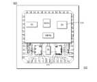
- such a design 100has only been implemented for a PA, in this case a dual-band amplifier, whereby a first amplifier 110 is designed for GSM, and a second amplifier 105 is designed for DCS-PCS operation. Furthermore, due to space constraints in being able to build an RF module using such lead-frame technology, the only other component on the die is the power amplifiers' associated control functionality 115 .
- the whole packageis configured in a 7 ⁇ 7 mm plastic package.
- PCT application—US2004/0232982 A1by Ichitsubo et. al., describes an RF front-end module for wireless communication devices, and is notably focused on the avoidance of using a printed circuit board (PCB)/LTCC and surface mount technologies (SMTs).
- PCBprinted circuit board
- SMTssurface mount technologies
- none of the above citationsadequately address the aforementioned problem of implementing a RF power module having an improved power performance.
- none of the above citationsdisclose a mechanism that improves power added efficiency, where sufficiently less die size is required to implementing high-Q components, such as inductors, capacitors and RF chokes.
- the RF die groundingis realized by soldering the die 205 , using tin lead solder, or gold tin eutectic solder), directly on a metallic flange heatsink 220 , as illustrated in the circuit arrangement 200 of FIG. 2 .
- the active dieis operably coupled to substantially co-located PCBS 210 via wire-bonds 215 .
- This known artallows the best thermal contact between the die active area 205 and the best electrical contact for the grounding. It is also well known that a resistive or inductive grounding of the RF power device generates fast degradation of power gain and power added efficiency.
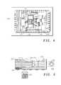
- FIG. 3a similar structure 300 is illustrated in FIG. 3 , which has been widely used as a low cost structure.
- an active die 305is directly coupled to surface mounted components on a PCB 310 via wire-bonds 315 .
- a primary weakness of this structureis a significantly worse grounding, as compared to the RF die grounding of soldering directly on a metallic flange as shown in FIG. 2 . This remains the case even if there is a large number of via holes 320 underneath the active die 305 .
- a lead-frame circuit packagethat comprises a multi-layered substrate therefor, a multi-layer substrate and a wireless communication unit having a lead-frame circuit package as a front-end module, as defined in the appended Claims.
- FIG. 1illustrates a known RF power amplifier integrated circuit that uses lead-frame inductors
- FIG. 2illustrates a known integrated circuit structure
- FIG. 3illustrates a second known integrated circuit structure.
- FIG. 4illustrates a first example of a complete RF front-end module, utilising lead-frame technology, and constructed in accordance with the preferred embodiment of the present invention
- FIG. 5illustrates a diagram of a multi-layer substrate employed in accordance with the preferred embodiment of the present invention
- FIG. 6illustrates a second example of a complete RF front-end module, utilising lead-frame technology, and constructed in accordance with the preferred embodiment of the present invention
- FIG. 7illustrates one example of an application to facilitate the lead-frame packaging, in accordance with the preferred embodiment of the present invention
- FIG. 8illustrates a further cross-section example of a standard multi-layer substrate and a HDI substrate, adapted for use in accordance with the preferred embodiment of the present invention.
- FIG. 9illustrates a cross-section of a lead-frame package with an exposed pad, in accordance with the preferred embodiment of the present invention.
- the preferred embodiment of the present inventionwill be described in terms of a lead-frame package for a radio frequency (RF) power amplifier (PA) module capable of operation in digital wireless cellular communication units, such as GSM, Edge, or 3 rd generation (3G) cellular phones.
- RFradio frequency
- PApower amplifier
- digital wireless cellular communication unitssuch as GSM, Edge, or 3 rd generation (3G) cellular phones.
- inventive concepts herein describedmay be embodied in any radio frequency amplifier device or apparatus.
- the term ‘lead-frame packaging’encompasses, at least, any metal frame that provides external electrical connection to a packaged integrated circuit (IC) or chip, as they are commonly referred to.
- substrateencompasses, at least, any organic or ceramic printed circuit board (PCB) that provides internal (die to die and/or die to surface mount technology (SMT) components) and external electrical connection to the packaged chip.
- PCBprinted circuit board
- SMTsurface mount technology
- a PCBmay also embed some devices, such as capacitors, inductors, filters etc.
- the term ‘high density integration’ (HDI)when applied to a substrate, encompasses, at least, any high density interconnect.
- a substrateis located on a die within a lead-frame circuit package and used for several functions.
- the simplest functionis its use in re-routeing wire-bonding from the lead-frame package to the die and/or the die to another die and/or a substrate to another substrate.
- any combination of routeingis envisaged within the lead-frame packaging.
- the substrateis used to support die routing or having embedded components, such as capacitors or inductors located therein, a multi-layer substrate or HDI type of substrate is generally needed. It is envisaged that the substrate could be organic or ceramic.
- the preferred embodiment of the present inventionproposes the use of a High Density integration (HDI) printed circuit board (PCB) or Low temperature Co-fired Ceramic (LTCC) substrate inside such a lead-frame package for Radio Frequency modules/operation.
- HDIHigh Density integration
- PCBprinted circuit board
- LTCCLow temperature Co-fired Ceramic
- a PA diehas an improved performance using a lead-frame packaging, whilst the use of a substrate allows advantageous signal routing and increased track space to provide, for example, choke inductance.
- This configurationresolves the problem associated with using lead-frame packages, which are renowned as providing poor routeing capability.
- lead-frame packagesare typically unsuitable for high level integration around the PA die and consequently unsuitable for designs of complete front-end modules or complete radio modules.
- this configuration of using a substrate on a die within a lead-frame plastic packageenables the PA module to provide even more power added efficiency (PAE).
- PAEpower added efficiency
- PAsPower amplifiers
- FEMsfront-end modules
- the lead-frame packageis configured with an exposed pad that facilitates high routeing capability for ‘in-package’ systems.
- Thisenables a substantially equal performance for the RF power amplifier versus known prior art lead-frame packaged PAs and FEMs.
- the provision of a multi-layer substrate to facilitate a substantial amount of the signal routeing, as well as a number of inductive components such as RF chokes,also enables the inventive concept to be used in ‘systems-in-package’ type applications.
- the inventive concept of the present inventionutilizes the benefits known from using multilayer substrates together with benefits provided by lead-frame technologies.
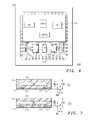
- FIG. 4a first example of a complete RF front-end module 400 is illustrated in FIG. 4 .
- the complete RF front-end module 400utilises lead-frame technology.
- a substrate 410is arranged to provide a substantial number of the high-Q components.
- the substrateis arranged to sit on an exposed pad where all connections are wire bonded to the substrate.
- other means of connecting wires to the substratemay be used, such as bumped substrate or a substrate with a back side pattern, allowing back side attach with conductive glue or solder, for example tin lead solder.
- conductive glue or solderfor example tin lead solder.
- solderis located similar to any dice on a lead-frame flag or leads.
- RF high-Q inductors 405are configured by using primarily wire bonds and leads to the substrate as bonding pad with tuneability.
- tuneabilitymeans that by changing the wire-bonding length or position of some wires, the inductor can be tuned, i.e. all the parameters that will define the loop profile of the wire-bonding may be adjusted to achieve the desired performance.
- a HDI substrate 410is used, in effect, as a surface mounted device (SMD) that contains, say, high-Q choke inductors and a 2 nd matching inductor for, say, a high-band PA.
- a HDI substrateis a multi-layer organic PCB including a thin dielectric layer (pregreg) on each side of a core dielectric layer.
- a typical HDI substrate 500adapted for use in the preferred embodiment of the present invention, is illustrated in FIG. 5 .
- the pregreg layerspreferably include small vias, generally laser drilled instead of standard mechanical drilling.
- the advantage of the HDI substrateis the small size that can be used for a via, enabling higher density interconnections versus the standard multi-layer PCB. Vias may be filled or not with copper to allow maximum thermal dissipation.
- the HDI substrate 500could be used to embed discrete components, such as capacitors 505 , 510 and/or inductors 515 and/or filters and/or resistors 525 .
- discrete componentssuch as capacitors 505 , 510 and/or inductors 515 and/or filters and/or resistors 525 .
- a PA diesits on a standard lead-frame or an exposed pad 415 . It has been found that locating the PA die on an exposed pad obtains an optimal performance.
- the exposed padprovides excellent RF grounding of RF transistors, at low cost, whilst achieving the best power gain and PAE, as illustrated in, and described later with respect to, FIG. 9 .
- high-Q inductors and capacitorsAnother critical component in achieving a high PAE performance in PA modules is the provision of high-Q inductors and capacitors. It is proposed that high-Q surface mounted devices (SMDs) are included within the lead-frame packaging and used to provide some of the capacitors, inductors and RF chokes in the PA design. Alternatively, high-Q capacitors can be realized using Metal Insulator Metal (MIM) caps in Gallium Arsenide (GaAs).
- MIMMetal Insulator Metal
- the complete RF front-end module 400 in FIG. 4also comprises a controller device and other front-end die components such as a harmonic filter and switch (not shown), which both are arranged to sit on the exposed pad.
- a die 415including two RF amplifiers, sits on an exposed pad; together with the biasing controller die 420 , two harmonic filters 425 and an antenna switch 430 .
- a second example of a complete RF front-end module 600is illustrated, where the RF front-end module again utilises lead-frame technology, and is constructed in accordance with the preferred embodiment of the present invention.
- the multi-layer substrateis arranged to sit on exposed pad and is operably connected to the exposed pad of the PA die, via leads.
- a number of RF high-Q inductors 605primarily use wire bonds to connect to the PA die, with the high-Q performance provided by routeing within the multi-layer substrate.
- the HDI multi-layer substrateis preferably arranged to sit on leads using, for example, chip on leads technique (COL), as described in MicroLeadFrame® package from AMKORTM, or using flip-chip technology, as described in U.S. Pat. Nos. 6,750,546 B1 or 6,597,059 B1.
- COLchip on leads technique
- controller and front-end die 610 of the complete RF front-end module 600are ‘flipped’ on the multi-layer substrate, thereby taking advantage of the HDI routeing capability.
- the PA die 615sits on an exposed pad for best performance.
- non-critical SMD componentsare preferably included within the lead-frame packaging.
- FIG. 7a diagram 700 of a multi-layer substrate is illustrated, that is locatable on the exposed pad of the lead-frame package, for example the lead-frame package illustrated in FIG. 4 or FIG. 6 .
- the multi-layer substrateencompasses metal tracks to facilitate signal routeing as well as microstrip lines to simulate the characteristics of an RF choke.
- the die 705is located within a moulded plastic body 710 .
- the die 705is attached to a copper lead-frame 715 via high lead, tin or gold solder bumps 720 .
- the moulded plastic bodycomprises half-etched areas 725 .
- one or more filters and/or the RF switchwould preferably be flipped on the substrate, as shown in the example arrangement 600 .
- a RF modulecould be implemented that encompasses a flip chip transceiver and a PA (wire bonded or flip chip) manufactured in SiGe or GaAs.
- this type of implementationmay remove the need for wire-bonding from the assembly process. Removing wire-bonding allows a manufacturer to decrease the die size because the bonding areas and bonding pad clearance are no longer needed. All interconnects (solder bumps) are located on chip and then the chip is flipped and soldered on with a dedicated metal pattern on the PCB.
- BOMbill of material
- the multi-layer substrate 800is a multi-layer organic PCB including a plurality of thin dielectric layers (pregreg) 805 on each side of a plurality of core dielectric layers 810 .
- the pregreg layers 805preferably include small vias generated using standard mechanical drilling 815 .
- Electrical conductors 820are illustrated on each of the pregreg layers 805 .
- FIG. 8A further cross-section example of an HDI substrate 850 is illustrated in FIG. 8 , as adapted in accordance with the preferred embodiment of the present invention.
- the HDI substrate 850is a multi-layer organic PCB including a plurality of thin dielectric layers (pregreg) 855 on each side of a plurality of core dielectric layers 860 .
- the pregreg layers 855preferably include small vias generated using laser drilling 865 .
- the advantage of the HDI substrateis the small size that can be used for a via, enabling higher density interconnections versus the standard multi-layer PCB.
- FIG. 9a cross-section of a lead-frame package with an exposed pad is illustrated, in accordance with the preferred embodiment of the present invention.
- the die 905is located on the exposed die pad 910 utilising a die attach material 925 .
- the lead-frame packagecomprises a copper lead-frame 915 and a moulded compound 920 .
- Gold wire bonding 930is used to connect the die to the lead-frame packaging.
- inventive concept of the present inventionmay be utilised with any type of lead-frame package such as Quad Flat No-lead (QFN) package, Thin Quad Flat Pack (TQFP) or Small Outline (SO) package, with or without exposed pads/ flags package.
- QFNQuad Flat No-lead
- TQFPThin Quad Flat Pack
- SOSmall Outline
- the multi-layer substrate used in the inventive concept of the present inventioncan be used to route tracks between active and/or passive dice and used to support flipped or non-flipped dice as well as SMDs.
- the multi-layer substratemay be arranged for use as a relay pad for High Impedance Integrated Power Amplifier (HIIPA) implementation, say using the impedance matching methods for power amplifiers as described on page 3 of U.S. Pat. No. 6,621,140 B1.
- HIIPAHigh Impedance Integrated Power Amplifier
- the inventive conceptcan be used in any RF module, such as a RF power amplifier or RF modem, particularly to provide a low cost RF package/ module for use in wireless communication units.
- RF modulesuch as a RF power amplifier or RF modem
- inventive conceptcan be used within any wireless communication technology, including: digital TV (Digital Video Broadcasting (DVB) and Integrated Services Digital Broadcasting (ISDB) units) second and/or third generation (3G) cellular phones (such as 3 rd Generation Partnership Project (3GPP), Multimedia Broadcast Multicast Service (MBMS)/ High Speed Downlink Packet Access (HSDPA), 3GPP2, Bluetooth capable units, Global System for Mobile communication (GSM), RF test equipment, private mobile radio, etc.
- 3GPP3 rd Generation Partnership Project
- MBMSMultimedia Broadcast Multicast Service
- HSDPAHigh Speed Downlink Packet Access
- GSMGlobal System for Mobile communication
- GSMGlobal System for Mobile communication
Landscapes
- Engineering & Computer Science (AREA)
- Computer Hardware Design (AREA)
- Microelectronics & Electronic Packaging (AREA)
- Power Engineering (AREA)
- Physics & Mathematics (AREA)
- Condensed Matter Physics & Semiconductors (AREA)
- General Physics & Mathematics (AREA)
- Amplifiers (AREA)
- Semiconductor Integrated Circuits (AREA)
- Microwave Amplifiers (AREA)
- Lead Frames For Integrated Circuits (AREA)
Abstract
Description
- (i) Substrate or leads;
- (ii) Printed circuit board (PCB) tracks on or in the substrate;
- (iii) Back and forth wire-bonding between a substrate and the dice; or
- (iv) Integrated passive devices (IPD) on substrate or leads; or
- (v) Any combination of the above four implementations.
- (i) The design benefits from the power capabilities and improved grounding of a lead-frame conductor, whilst also achieving the routeing capabilities provided by a multi-layer printed circuit substrate at low cost;
- (ii) The advantage (around 5% in PAE for a front-end module), is almost equivalent to the increment expected moving from one technology platform (i.e. active die) to another;
- (iii) It allows integration of a substantial portion of a RF front-end module on the substrate due to the substrate's routeing capability;
- (iv) High-Q inductors can be implemented using SMD technology within the substrate and therefore within the lead-frame package; and
- (v) Alternatively, use of metal layers of a multi-layer substrate allows high-Q inductors to be used, taking up a very small size as compared to package leads.
Claims (18)
Applications Claiming Priority (1)
| Application Number | Priority Date | Filing Date | Title |
|---|---|---|---|
| PCT/IB2005/001077WO2006090204A1 (en) | 2005-02-24 | 2005-02-24 | Lead-frame circuit package |
Related Parent Applications (1)
| Application Number | Title | Priority Date | Filing Date |
|---|---|---|---|
| PCT/IB2005/001077A-371-Of-InternationalWO2006090204A1 (en) | 2005-02-24 | 2005-02-24 | Lead-frame circuit package |
Related Child Applications (1)
| Application Number | Title | Priority Date | Filing Date |
|---|---|---|---|
| US14/285,079DivisionUS20140252570A1 (en) | 2005-02-24 | 2014-05-22 | Lead-frame circuit package |
Publications (2)
| Publication Number | Publication Date |
|---|---|
| US20080142935A1 US20080142935A1 (en) | 2008-06-19 |
| US8736034B2true US8736034B2 (en) | 2014-05-27 |
Family
ID=34982536
Family Applications (2)
| Application Number | Title | Priority Date | Filing Date |
|---|---|---|---|
| US11/816,038Active2027-11-17US8736034B2 (en) | 2005-02-24 | 2005-02-24 | Lead-frame circuit package |
| US14/285,079AbandonedUS20140252570A1 (en) | 2005-02-24 | 2014-05-22 | Lead-frame circuit package |
Family Applications After (1)
| Application Number | Title | Priority Date | Filing Date |
|---|---|---|---|
| US14/285,079AbandonedUS20140252570A1 (en) | 2005-02-24 | 2014-05-22 | Lead-frame circuit package |
Country Status (3)
| Country | Link |
|---|---|
| US (2) | US8736034B2 (en) |
| TW (1) | TW200711086A (en) |
| WO (1) | WO2006090204A1 (en) |
Cited By (4)
| Publication number | Priority date | Publication date | Assignee | Title |
|---|---|---|---|---|
| US20150201515A1 (en)* | 2014-01-13 | 2015-07-16 | Rf Micro Devices, Inc. | Surface finish for conductive features on substrates |
| US11145609B2 (en) | 2019-12-05 | 2021-10-12 | Nxp Usa, Inc. | Doherty amplifier with surface-mount packaged carrier and peaking amplifiers |
| US11264251B2 (en)* | 2018-11-29 | 2022-03-01 | Wavepia Co., Ltd. | Method of manufacturing power amplifier package embedded with input-output circuit |
| US11309926B2 (en)* | 2013-04-24 | 2022-04-19 | Skyworks Solutions, Inc. | Multiple band multiple mode transceiver front end flip-chip architecture and circuitry with integrated power amplifiers |
Families Citing this family (16)
| Publication number | Priority date | Publication date | Assignee | Title |
|---|---|---|---|---|
| KR100747978B1 (en)* | 2005-06-17 | 2007-08-08 | 엘지이노텍 주식회사 | Front end module and fabricating method thereof |
| US20090032917A1 (en)* | 2007-08-02 | 2009-02-05 | M/A-Com, Inc. | Lead frame package apparatus and method |
| US8049319B2 (en)* | 2008-10-24 | 2011-11-01 | Electronics And Telecommunications Research Institute | Ultra wideband system-on-package |
| US8698244B2 (en) | 2009-11-30 | 2014-04-15 | International Business Machines Corporation | Silicon-on-insulator (SOI) structure configured for reduced harmonics, design structure and method |
| US8471340B2 (en) | 2009-11-30 | 2013-06-25 | International Business Machines Corporation | Silicon-on-insulator (SOI) structure configured for reduced harmonics and method of forming the structure |
| CN103026634B (en)* | 2010-05-21 | 2015-05-27 | 马维尔国际贸易有限公司 | RF front-end with integrated t/r switch |
| US8886136B1 (en) | 2011-04-22 | 2014-11-11 | Marvell International Ltd. | Two-pin TR switch with switched capacitor |
| KR101434003B1 (en) | 2011-07-07 | 2014-08-27 | 삼성전기주식회사 | Semiconductor package and manufacturing method thereof |
| US9679869B2 (en)* | 2011-09-02 | 2017-06-13 | Skyworks Solutions, Inc. | Transmission line for high performance radio frequency applications |
| US9325353B2 (en)* | 2011-09-16 | 2016-04-26 | Rf Micro Devices, Inc. | Architecture for a radio frequency front-end |
| CN102623416B (en)* | 2012-04-24 | 2015-09-02 | 苏州远创达科技有限公司 | A kind of power device of radio frequency power amplification modules is without encapsulating structure and assemble method thereof |
| US9941242B2 (en) | 2012-04-24 | 2018-04-10 | Innogration (Suzhou) Co., Ltd. | Unpacked structure for power device of radio frequency power amplification module and assembly method therefor |
| GB2511732B (en)* | 2013-02-01 | 2015-11-18 | Cambridge Comm Systems Ltd | Antenna arrangement of a wireless node |
| US10887439B2 (en)* | 2015-12-22 | 2021-01-05 | Intel Corporation | Microelectronic devices designed with integrated antennas on a substrate |
| WO2019172332A1 (en)* | 2018-03-07 | 2019-09-12 | Sumitomo Electric Device Innovations, Inc. | Semiconductor device |
| US20230395478A1 (en)* | 2022-06-01 | 2023-12-07 | Aselsan Elektronik Sanayi Ve Ticaret Anonim Sirketi | Chip scale qfn plastic packaging system for high frequency integrated circuits |
Citations (10)
| Publication number | Priority date | Publication date | Assignee | Title |
|---|---|---|---|---|
| US5536906A (en) | 1993-07-23 | 1996-07-16 | Texas Instruments Incorporated | Package for integrated circuits |
| JPH10242377A (en) | 1997-02-25 | 1998-09-11 | Hitachi Ltd | High frequency power amplifier module |
| US20020140075A1 (en) | 2001-03-27 | 2002-10-03 | Ericsson Inc. | Power transistor package with integrated flange for surface mount heat removal |
| US6608367B1 (en)* | 2002-02-25 | 2003-08-19 | Rf Micro Devices, Inc. | Leadframe inductors |
| EP1357596A2 (en) | 2002-04-22 | 2003-10-29 | NEC Compound Semiconductor Devices, Ltd. | Semiconductor device and method of fabricating the same |
| US20030209784A1 (en) | 2002-05-09 | 2003-11-13 | Schmitz Norbert A. | Package for integrated circuit with internal matching |
| US6750546B1 (en) | 2001-11-05 | 2004-06-15 | Skyworks Solutions, Inc. | Flip-chip leadframe package |
| US20040201423A1 (en) | 2003-04-14 | 2004-10-14 | M/A-Com, Inc. | Handset radiofrequency front end module in fine pitch quad flat no lead (FQFP-N) package |
| US20040232982A1 (en) | 2002-07-19 | 2004-11-25 | Ikuroh Ichitsubo | RF front-end module for wireless communication devices |
| US7113054B2 (en) | 2001-02-28 | 2006-09-26 | Freescale Semiconductor, Inc. | Arrangement and method impedance matching |
Family Cites Families (2)
| Publication number | Priority date | Publication date | Assignee | Title |
|---|---|---|---|---|
| US6633005B2 (en)* | 2001-10-22 | 2003-10-14 | Micro Mobio Corporation | Multilayer RF amplifier module |
| US6982483B2 (en)* | 2003-05-30 | 2006-01-03 | Freescale Semiconductor, Inc. | High impedance radio frequency power plastic package |
- 2005
- 2005-02-24WOPCT/IB2005/001077patent/WO2006090204A1/ennot_activeApplication Discontinuation
- 2005-02-24USUS11/816,038patent/US8736034B2/enactiveActive
- 2006
- 2006-02-23TWTW095106020Apatent/TW200711086A/enunknown
- 2014
- 2014-05-22USUS14/285,079patent/US20140252570A1/ennot_activeAbandoned
Patent Citations (11)
| Publication number | Priority date | Publication date | Assignee | Title |
|---|---|---|---|---|
| US5536906A (en) | 1993-07-23 | 1996-07-16 | Texas Instruments Incorporated | Package for integrated circuits |
| JPH10242377A (en) | 1997-02-25 | 1998-09-11 | Hitachi Ltd | High frequency power amplifier module |
| US7113054B2 (en) | 2001-02-28 | 2006-09-26 | Freescale Semiconductor, Inc. | Arrangement and method impedance matching |
| US20020140075A1 (en) | 2001-03-27 | 2002-10-03 | Ericsson Inc. | Power transistor package with integrated flange for surface mount heat removal |
| US6750546B1 (en) | 2001-11-05 | 2004-06-15 | Skyworks Solutions, Inc. | Flip-chip leadframe package |
| US6608367B1 (en)* | 2002-02-25 | 2003-08-19 | Rf Micro Devices, Inc. | Leadframe inductors |
| US6621140B1 (en) | 2002-02-25 | 2003-09-16 | Rf Micro Devices, Inc. | Leadframe inductors |
| EP1357596A2 (en) | 2002-04-22 | 2003-10-29 | NEC Compound Semiconductor Devices, Ltd. | Semiconductor device and method of fabricating the same |
| US20030209784A1 (en) | 2002-05-09 | 2003-11-13 | Schmitz Norbert A. | Package for integrated circuit with internal matching |
| US20040232982A1 (en) | 2002-07-19 | 2004-11-25 | Ikuroh Ichitsubo | RF front-end module for wireless communication devices |
| US20040201423A1 (en) | 2003-04-14 | 2004-10-14 | M/A-Com, Inc. | Handset radiofrequency front end module in fine pitch quad flat no lead (FQFP-N) package |
Non-Patent Citations (3)
| Title |
|---|
| Bessemoulin et al; "1-Watt Ku-band Power Amplifier MMICs using Low-cost Quad-Flat Plastic Package"; 2004 IEEE MTT-S Digest, pp. 473-476. |
| Reidy et al; "Supercritical Silyation of Ashed Si-O-C Low-K Films to Limit Changes in Critical Dimensions"; 2004 Materials Research Society Conference Proceedings, pp. 513-517. |
| Saso et al; "0.1 CC 60% Efficiency Power Amplifier Multi-Chip Modules for Personal Digital Cellular Phones"; 1999 IEEE MTT-S Digest, pp. 1401-1404. |
Cited By (4)
| Publication number | Priority date | Publication date | Assignee | Title |
|---|---|---|---|---|
| US11309926B2 (en)* | 2013-04-24 | 2022-04-19 | Skyworks Solutions, Inc. | Multiple band multiple mode transceiver front end flip-chip architecture and circuitry with integrated power amplifiers |
| US20150201515A1 (en)* | 2014-01-13 | 2015-07-16 | Rf Micro Devices, Inc. | Surface finish for conductive features on substrates |
| US11264251B2 (en)* | 2018-11-29 | 2022-03-01 | Wavepia Co., Ltd. | Method of manufacturing power amplifier package embedded with input-output circuit |
| US11145609B2 (en) | 2019-12-05 | 2021-10-12 | Nxp Usa, Inc. | Doherty amplifier with surface-mount packaged carrier and peaking amplifiers |
Also Published As
| Publication number | Publication date |
|---|---|
| TW200711086A (en) | 2007-03-16 |
| US20080142935A1 (en) | 2008-06-19 |
| US20140252570A1 (en) | 2014-09-11 |
| WO2006090204A1 (en) | 2006-08-31 |
Similar Documents
| Publication | Publication Date | Title |
|---|---|---|
| US20140252570A1 (en) | Lead-frame circuit package | |
| US11984423B2 (en) | Radio frequency transmission line with finish plating on conductive layer | |
| US7348856B2 (en) | Semiconductor device | |
| KR100993277B1 (en) | Semiconductor device and electronic device | |
| US20060261460A1 (en) | Semiconductor device | |
| KR100993579B1 (en) | Semiconductor device and electronic device | |
| CN101789421B (en) | Semiconductor device | |
| US20100123228A1 (en) | Package including proximately-positioned lead frame | |
| TWI292208B (en) | ||
| JP7275177B2 (en) | Radio frequency package mounting window frame with edge plating and process for mounting same | |
| WO1999054935A1 (en) | Portable communication equipment | |
| US20230035978A1 (en) | High-frequency module and communication device | |
| TW200307359A (en) | Semiconductor device and electronic apparatus | |
| WO2022209731A1 (en) | High-frequency module and communication device |
Legal Events
| Date | Code | Title | Description |
|---|---|---|---|
| AS | Assignment | Owner name:FREESCALE SEMICONDUCTOR, INC., TEXAS Free format text:ASSIGNMENT OF ASSIGNORS INTEREST;ASSIGNORS:MONTORIOL, GILLES;DELAUNAY, THIERRY;TILHAC, FREDERIC;SIGNING DATES FROM 20060327 TO 20060406;REEL/FRAME:019763/0113 Owner name:FREESCALE SEMICONDUCTOR, INC., TEXAS Free format text:ASSIGNMENT OF ASSIGNORS INTEREST;ASSIGNORS:MONTORIOL, GILLES;DELAUNAY, THIERRY;TILHAC, FREDERIC;REEL/FRAME:019763/0113;SIGNING DATES FROM 20060327 TO 20060406 | |
| AS | Assignment | Owner name:CITIBANK, N.A.,NEW YORK Free format text:SECURITY AGREEMENT;ASSIGNOR:FREESCALE SEMICONDUCTOR, INC.;REEL/FRAME:020518/0215 Effective date:20071025 Owner name:CITIBANK, N.A., NEW YORK Free format text:SECURITY AGREEMENT;ASSIGNOR:FREESCALE SEMICONDUCTOR, INC.;REEL/FRAME:020518/0215 Effective date:20071025 | |
| AS | Assignment | Owner name:CITIBANK, N.A., NEW YORK Free format text:SECURITY AGREEMENT;ASSIGNOR:FREESCALE SEMICONDUCTOR, INC.;REEL/FRAME:024085/0001 Effective date:20100219 Owner name:CITIBANK, N.A.,NEW YORK Free format text:SECURITY AGREEMENT;ASSIGNOR:FREESCALE SEMICONDUCTOR, INC.;REEL/FRAME:024085/0001 Effective date:20100219 | |
| AS | Assignment | Owner name:CITIBANK, N.A., AS COLLATERAL AGENT, NEW YORK Free format text:SECURITY AGREEMENT;ASSIGNOR:FREESCALE SEMICONDUCTOR, INC.;REEL/FRAME:024397/0001 Effective date:20100413 Owner name:CITIBANK, N.A., AS COLLATERAL AGENT,NEW YORK Free format text:SECURITY AGREEMENT;ASSIGNOR:FREESCALE SEMICONDUCTOR, INC.;REEL/FRAME:024397/0001 Effective date:20100413 | |
| AS | Assignment | Owner name:CITIBANK, N.A., AS NOTES COLLATERAL AGENT, NEW YORK Free format text:SECURITY AGREEMENT;ASSIGNOR:FREESCALE SEMICONDUCTOR, INC.;REEL/FRAME:030633/0424 Effective date:20130521 Owner name:CITIBANK, N.A., AS NOTES COLLATERAL AGENT, NEW YOR Free format text:SECURITY AGREEMENT;ASSIGNOR:FREESCALE SEMICONDUCTOR, INC.;REEL/FRAME:030633/0424 Effective date:20130521 | |
| AS | Assignment | Owner name:CITIBANK, N.A., AS NOTES COLLATERAL AGENT, NEW YORK Free format text:SECURITY AGREEMENT;ASSIGNOR:FREESCALE SEMICONDUCTOR, INC.;REEL/FRAME:031591/0266 Effective date:20131101 Owner name:CITIBANK, N.A., AS NOTES COLLATERAL AGENT, NEW YOR Free format text:SECURITY AGREEMENT;ASSIGNOR:FREESCALE SEMICONDUCTOR, INC.;REEL/FRAME:031591/0266 Effective date:20131101 | |
| STCF | Information on status: patent grant | Free format text:PATENTED CASE | |
| FEPP | Fee payment procedure | Free format text:PAYOR NUMBER ASSIGNED (ORIGINAL EVENT CODE: ASPN); ENTITY STATUS OF PATENT OWNER: LARGE ENTITY | |
| AS | Assignment | Owner name:FREESCALE SEMICONDUCTOR, INC., TEXAS Free format text:PATENT RELEASE;ASSIGNOR:CITIBANK, N.A., AS COLLATERAL AGENT;REEL/FRAME:037356/0553 Effective date:20151207 Owner name:FREESCALE SEMICONDUCTOR, INC., TEXAS Free format text:PATENT RELEASE;ASSIGNOR:CITIBANK, N.A., AS COLLATERAL AGENT;REEL/FRAME:037356/0143 Effective date:20151207 Owner name:FREESCALE SEMICONDUCTOR, INC., TEXAS Free format text:PATENT RELEASE;ASSIGNOR:CITIBANK, N.A., AS COLLATERAL AGENT;REEL/FRAME:037354/0704 Effective date:20151207 | |
| AS | Assignment | Owner name:MORGAN STANLEY SENIOR FUNDING, INC., MARYLAND Free format text:ASSIGNMENT AND ASSUMPTION OF SECURITY INTEREST IN PATENTS;ASSIGNOR:CITIBANK, N.A.;REEL/FRAME:037518/0292 Effective date:20151207 | |
| AS | Assignment | Owner name:MORGAN STANLEY SENIOR FUNDING, INC., MARYLAND Free format text:SECURITY AGREEMENT SUPPLEMENT;ASSIGNOR:NXP B.V.;REEL/FRAME:038017/0058 Effective date:20160218 | |
| AS | Assignment | Owner name:MORGAN STANLEY SENIOR FUNDING, INC., MARYLAND Free format text:SUPPLEMENT TO THE SECURITY AGREEMENT;ASSIGNOR:FREESCALE SEMICONDUCTOR, INC.;REEL/FRAME:039138/0001 Effective date:20160525 | |
| AS | Assignment | Owner name:MORGAN STANLEY SENIOR FUNDING, INC., MARYLAND Free format text:CORRECTIVE ASSIGNMENT TO CORRECT THE REMOVE APPLICATION 12092129 PREVIOUSLY RECORDED ON REEL 038017 FRAME 0058. ASSIGNOR(S) HEREBY CONFIRMS THE SECURITY AGREEMENT SUPPLEMENT;ASSIGNOR:NXP B.V.;REEL/FRAME:039361/0212 Effective date:20160218 | |
| AS | Assignment | Owner name:NXP USA, INC., TEXAS Free format text:CHANGE OF NAME;ASSIGNOR:FREESCALE SEMICONDUCTOR INC.;REEL/FRAME:040652/0180 Effective date:20161107 | |
| AS | Assignment | Owner name:NXP USA, INC., TEXAS Free format text:CORRECTIVE ASSIGNMENT TO CORRECT THE NATURE OF CONVEYANCE LISTED CHANGE OF NAME SHOULD BE MERGER AND CHANGE PREVIOUSLY RECORDED AT REEL: 040652 FRAME: 0180. ASSIGNOR(S) HEREBY CONFIRMS THE MERGER AND CHANGE OF NAME;ASSIGNOR:FREESCALE SEMICONDUCTOR INC.;REEL/FRAME:041354/0148 Effective date:20161107 | |
| AS | Assignment | Owner name:MORGAN STANLEY SENIOR FUNDING, INC., MARYLAND Free format text:CORRECTIVE ASSIGNMENT TO CORRECT THE REMOVE PATENTS 8108266 AND 8062324 AND REPLACE THEM WITH 6108266 AND 8060324 PREVIOUSLY RECORDED ON REEL 037518 FRAME 0292. ASSIGNOR(S) HEREBY CONFIRMS THE ASSIGNMENT AND ASSUMPTION OF SECURITY INTEREST IN PATENTS;ASSIGNOR:CITIBANK, N.A.;REEL/FRAME:041703/0536 Effective date:20151207 | |
| AS | Assignment | Owner name:MORGAN STANLEY SENIOR FUNDING, INC., MARYLAND Free format text:CORRECTIVE ASSIGNMENT TO CORRECT THE REMOVE APPLICATION 12681366 PREVIOUSLY RECORDED ON REEL 038017 FRAME 0058. ASSIGNOR(S) HEREBY CONFIRMS THE SECURITY AGREEMENT SUPPLEMENT;ASSIGNOR:NXP B.V.;REEL/FRAME:042985/0001 Effective date:20160218 Owner name:MORGAN STANLEY SENIOR FUNDING, INC., MARYLAND Free format text:CORRECTIVE ASSIGNMENT TO CORRECT THE REMOVE APPLICATION 12681366 PREVIOUSLY RECORDED ON REEL 039361 FRAME 0212. ASSIGNOR(S) HEREBY CONFIRMS THE SECURITY AGREEMENT SUPPLEMENT;ASSIGNOR:NXP B.V.;REEL/FRAME:042762/0145 Effective date:20160218 | |
| MAFP | Maintenance fee payment | Free format text:PAYMENT OF MAINTENANCE FEE, 4TH YEAR, LARGE ENTITY (ORIGINAL EVENT CODE: M1551) Year of fee payment:4 | |
| AS | Assignment | Owner name:SHENZHEN XINGUODU TECHNOLOGY CO., LTD., CHINA Free format text:CORRECTIVE ASSIGNMENT TO CORRECT THE TO CORRECT THE APPLICATION NO. FROM 13,883,290 TO 13,833,290 PREVIOUSLY RECORDED ON REEL 041703 FRAME 0536. ASSIGNOR(S) HEREBY CONFIRMS THE THE ASSIGNMENT AND ASSUMPTION OF SECURITYINTEREST IN PATENTS.;ASSIGNOR:MORGAN STANLEY SENIOR FUNDING, INC.;REEL/FRAME:048734/0001 Effective date:20190217 | |
| AS | Assignment | Owner name:NXP B.V., NETHERLANDS Free format text:RELEASE BY SECURED PARTY;ASSIGNOR:MORGAN STANLEY SENIOR FUNDING, INC.;REEL/FRAME:050744/0097 Effective date:20190903 Owner name:NXP B.V., NETHERLANDS Free format text:RELEASE BY SECURED PARTY;ASSIGNOR:MORGAN STANLEY SENIOR FUNDING, INC.;REEL/FRAME:050745/0001 Effective date:20190903 | |
| AS | Assignment | Owner name:MORGAN STANLEY SENIOR FUNDING, INC., MARYLAND Free format text:CORRECTIVE ASSIGNMENT TO CORRECT THE REMOVE APPLICATION 12298143 PREVIOUSLY RECORDED ON REEL 042985 FRAME 0001. ASSIGNOR(S) HEREBY CONFIRMS THE SECURITY AGREEMENT SUPPLEMENT;ASSIGNOR:NXP B.V.;REEL/FRAME:051029/0001 Effective date:20160218 Owner name:MORGAN STANLEY SENIOR FUNDING, INC., MARYLAND Free format text:CORRECTIVE ASSIGNMENT TO CORRECT THE REMOVE APPLICATION 12298143 PREVIOUSLY RECORDED ON REEL 042762 FRAME 0145. ASSIGNOR(S) HEREBY CONFIRMS THE SECURITY AGREEMENT SUPPLEMENT;ASSIGNOR:NXP B.V.;REEL/FRAME:051145/0184 Effective date:20160218 Owner name:MORGAN STANLEY SENIOR FUNDING, INC., MARYLAND Free format text:CORRECTIVE ASSIGNMENT TO CORRECT THE REMOVE APPLICATION 12298143 PREVIOUSLY RECORDED ON REEL 039361 FRAME 0212. ASSIGNOR(S) HEREBY CONFIRMS THE SECURITY AGREEMENT SUPPLEMENT;ASSIGNOR:NXP B.V.;REEL/FRAME:051029/0387 Effective date:20160218 Owner name:MORGAN STANLEY SENIOR FUNDING, INC., MARYLAND Free format text:CORRECTIVE ASSIGNMENT TO CORRECT THE REMOVE APPLICATION12298143 PREVIOUSLY RECORDED ON REEL 042762 FRAME 0145. ASSIGNOR(S) HEREBY CONFIRMS THE SECURITY AGREEMENT SUPPLEMENT;ASSIGNOR:NXP B.V.;REEL/FRAME:051145/0184 Effective date:20160218 Owner name:MORGAN STANLEY SENIOR FUNDING, INC., MARYLAND Free format text:CORRECTIVE ASSIGNMENT TO CORRECT THE REMOVE APPLICATION12298143 PREVIOUSLY RECORDED ON REEL 039361 FRAME 0212. ASSIGNOR(S) HEREBY CONFIRMS THE SECURITY AGREEMENT SUPPLEMENT;ASSIGNOR:NXP B.V.;REEL/FRAME:051029/0387 Effective date:20160218 Owner name:MORGAN STANLEY SENIOR FUNDING, INC., MARYLAND Free format text:CORRECTIVE ASSIGNMENT TO CORRECT THE REMOVE APPLICATION12298143 PREVIOUSLY RECORDED ON REEL 042985 FRAME 0001. ASSIGNOR(S) HEREBY CONFIRMS THE SECURITY AGREEMENT SUPPLEMENT;ASSIGNOR:NXP B.V.;REEL/FRAME:051029/0001 Effective date:20160218 Owner name:MORGAN STANLEY SENIOR FUNDING, INC., MARYLAND Free format text:CORRECTIVE ASSIGNMENT TO CORRECT THE REMOVE APPLICATION 12298143 PREVIOUSLY RECORDED ON REEL 038017 FRAME 0058. ASSIGNOR(S) HEREBY CONFIRMS THE SECURITY AGREEMENT SUPPLEMENT;ASSIGNOR:NXP B.V.;REEL/FRAME:051030/0001 Effective date:20160218 | |
| MAFP | Maintenance fee payment | Free format text:PAYMENT OF MAINTENANCE FEE, 8TH YEAR, LARGE ENTITY (ORIGINAL EVENT CODE: M1552); ENTITY STATUS OF PATENT OWNER: LARGE ENTITY Year of fee payment:8 | |
| AS | Assignment | Owner name:CHIP PACKAGING TECHNOLOGIES, LLC, TEXAS Free format text:ASSIGNMENT OF ASSIGNORS INTEREST;ASSIGNOR:NXP USA, INC.;REEL/FRAME:068541/0903 Effective date:20240731 |