US8735755B2 - Capacitive keyswitch technologies - Google Patents
Capacitive keyswitch technologiesDownload PDFInfo
- Publication number
- US8735755B2 US8735755B2US13/413,639US201213413639AUS8735755B2US 8735755 B2US8735755 B2US 8735755B2US 201213413639 AUS201213413639 AUS 201213413639AUS 8735755 B2US8735755 B2US 8735755B2
- Authority
- US
- United States
- Prior art keywords
- electrodes
- keycap
- electrode
- capacitance
- keyboard
- Prior art date
- Legal status (The legal status is an assumption and is not a legal conclusion. Google has not performed a legal analysis and makes no representation as to the accuracy of the status listed.)
- Active, expires
Links
Images


Classifications
- H—ELECTRICITY
- H03—ELECTRONIC CIRCUITRY
- H03K—PULSE TECHNIQUE
- H03K17/00—Electronic switching or gating, i.e. not by contact-making and –breaking
- H03K17/94—Electronic switching or gating, i.e. not by contact-making and –breaking characterised by the way in which the control signals are generated
- H03K17/96—Touch switches
- H03K17/962—Capacitive touch switches
- H03K17/9622—Capacitive touch switches using a plurality of detectors, e.g. keyboard
- H—ELECTRICITY
- H03—ELECTRONIC CIRCUITRY
- H03K—PULSE TECHNIQUE
- H03K17/00—Electronic switching or gating, i.e. not by contact-making and –breaking
- H03K17/94—Electronic switching or gating, i.e. not by contact-making and –breaking characterised by the way in which the control signals are generated
- H03K17/96—Touch switches
- H03K17/962—Capacitive touch switches
- H—ELECTRICITY
- H03—ELECTRONIC CIRCUITRY
- H03K—PULSE TECHNIQUE
- H03K17/00—Electronic switching or gating, i.e. not by contact-making and –breaking
- H03K17/94—Electronic switching or gating, i.e. not by contact-making and –breaking characterised by the way in which the control signals are generated
- H03K17/965—Switches controlled by moving an element forming part of the switch
- H03K17/975—Switches controlled by moving an element forming part of the switch using a capacitive movable element
- H03K17/98—Switches controlled by moving an element forming part of the switch using a capacitive movable element having a plurality of control members, e.g. keyboard
- H—ELECTRICITY
- H03—ELECTRONIC CIRCUITRY
- H03K—PULSE TECHNIQUE
- H03K2217/00—Indexing scheme related to electronic switching or gating, i.e. not by contact-making or -breaking covered by H03K17/00
- H03K2217/94—Indexing scheme related to electronic switching or gating, i.e. not by contact-making or -breaking covered by H03K17/00 characterised by the way in which the control signal is generated
- H03K2217/96—Touch switches
- H03K2217/9607—Capacitive touch switches
- H03K2217/960755—Constructional details of capacitive touch and proximity switches
- H03K2217/96077—Constructional details of capacitive touch and proximity switches comprising an electrode which is floating
Definitions
- a conventional keyboardtypically utilizes a sensor membrane of at least three layers and one or more non-tactile conductive-based switches to detect key depressions, where non-tactile means that the user feels nothing from switch closure itself (i.e., no feedback).
- a first portion of a circuitis provided on a first layer, a second portion of the circuit is provided on a second layer and a third non-conductive layer is disposed therebetween.
- a holeis generally provided in one or more of the layers such that, when a key is depressed, the first circuit portion is electrically coupled to the second circuit portion to complete an electric circuit.
- a controller associated with the keyboarddetects that a particular key is depressed and sends that information to a processor or other computing device.
- Multiple keysmay be provided in a matrix-like pattern such that a plurality of wiring patterns couples the plurality of keys to the controller. This layout is often referred to as a “keyboard switch matrix.”
- an apparatusincludes a key with a floating electrode.
- the floating electrodepairs with a fixed electrode and a capacitance may be generated between them.
- the apparatushas a controller configured to measure the capacitance as the electrodes move relative to each other as the key is depressed and released.
- FIGS. 1A , 1 B, and 1 Care three different views of a thin keyboard that incorporates one or more implementations of the capacitive keyswitches that are configured in accordance with the techniques described herein.
- FIG. 1Ais an isometric view of the keyboard.
- FIG. 1Bis top plan view of the keyboard.
- FIG. 1Cis a side elevation view of the keyboard.
- FIG. 2shows a block diagram of an example keyboard that is configured to implement the techniques described herein.
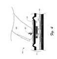
- FIG. 3shows a cross-sectional view of a portion of a keyboard that includes an example implementation of the keyswitch.
- FIG. 4shows the portion of the keyboard shown in FIG. 3 when the keyswitch is depressed by, for example, a finger.
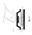
- FIG. 5shows a cross-sectional view of a portion of a keyboard that includes an alternative example implementation of the keyswitch.
- FIG. 6shows the portion of the keyboard shown in FIG. 6 when the keyswitch is depressed by, for example, a finger.
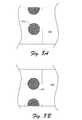
- FIG. 7Ashows a plan view of an upper membrane and a floating upper electrode of an exemplary keyswitch.
- FIG. 7Bshows a plan view of a lower membrane and lower electrodes of an exemplary keyswitch.
- FIG. 8Ashows a plan view of an alternative upper membrane and floating upper electrode of an alternative exemplary keyswitch.
- FIG. 8Bshows a plan view of an alternative lower membrane and lower electrodes of an alternative exemplary keyswitch.
- FIG. 9shows a block diagram of components of an example keyboard that is configured to implement the techniques described herein.
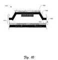
- FIG. 10shows a cross-sectional view of a portion of a keyboard that includes an example implementation of the keyswitch implemented with a light-plate membrane.
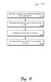
- FIG. 11shows a flow diagram of an example process that implements the techniques described herein.
- a keypress detection mechanismidentifies a keypress without “contacts” making physical contact with each other.
- a new keyswitch described hereinutilizes capacitive sensors, which are operable to sense capacitance, including measuring incremental changes in capacitance.
- the new keyswitchmay use mutual capacitance between one or more fixed electrodes (i.e., capacitance sensors) below a key and one or more floating electrodes (i.e., capacitance sensors) that is below, attached to, or part of, the moving key.
- each keyswitchhas a corresponding capacitive sensor that measures the force at which the user presses that key as a calibrated function of the change in capacitance measured or sensed by the sensor.
- the keyboarddetects a keypress of a particular key when the measured force being applied to the corresponding particular key exceeds a predefined and/or adjustable threshold.
- keypresses of each keymay be detected independently of the keypresses of others. Consequently, multiple keys may be pressed simultaneously regardless of their location on the keyboard.
- FIGS. 1A-1Coffer three different views of an exemplary keyboard 100 that is configured to implement the techniques described herein.
- FIG. 1Ais an isometric view of the exemplary keyboard 100 .
- FIG. 1Bis top plan view of the exemplary keyboard 100 .
- FIG. 1Cis a side elevation view of the exemplary keyboard 100 .
- the exemplary keyboard 100has a housing 102 and an array of keys 104 .
- the exemplary keyboard 100is exceptionally thin (i.e., low-profile) in contrast with a keyboard having conventional full-travel keys.
- a conventional keyboardis typically 12-30 mm thick (measured from the bottom of the keyboard housing to the top of the keycaps). Examples of such keyboards can be seen in the drawings of U.S. Pat. Nos. D278239, D292801, D284574, D527004, and D312623.
- the exemplary keyboard 100has a thickness 106 that is less than 4.0 mm thick (measured from the bottom of the keyboard housing to the top of the keycaps). With other implementations, the keyboard may be less than 3.0 mm or even 2.0 mm.
- the exemplary keyboard 100is shown as a stand-alone keyboard rather than one integrated with a computer, like the keyboards of a laptop computer.
- alternative implementationsmay have a keyboard integrated within the housing or chassis of the computer or other device components.
- the followingare examples of devices and systems that may use or include a keyboard like the exemplary keyboard 100 (by way of example only and not limitation): a mobile phone, electronic book, computer, laptop, tablet computer, stand-alone keyboard, input device, an accessory (such a tablet case with a build-in keyboard), monitor, electronic kiosk, gaming device, automated teller machine (ATM), vehicle dashboard, control panel, medical workstation, and industrial workstation.
- a touchpad and other input mechanismsare not shown on the keyboard 100
- alternative implementationsmay have a touchpad or other input mechanism integrated within the housing or chassis of the keyboard 100 .
- FIG. 2shows a simplified block diagram of an example keyboard that is configured to implement the techniques described herein. It is noted that certain well-known features are omitted for the purposes of clarity and simplicity of discussion.
- the exemplary keyboard 200includes an exemplary keyswitch matrix 201 that is coupled to a plurality of keyswitches 202 .
- the keyswitch matrix 201may optionally be provided with backlighting 204 to light the keyswitches 202 or their associated touchsurfaces (e.g., key caps) from below.
- the keyboard 100may also optionally include a touchpad 206 .
- the keyboard 100may have one or more controllers 208 to monitor the keyswitch matrix 201 and/or the touchpad 206 and to provide output to a computer processor (not shown) associated with or electrically coupled to the keyboard.
- keyboardsIn a conventional conductivity-based keyboard, such as a laptop computer keyboard, the keyswitch matrix has required its own dedicated controller and the touchpad has its own separate dedicated controller. These two distinct controllers have been required because the keyboard has traditionally been a matrix of non-tactile conductivity-based keyswitches while the touchpad employs capacitive technology to locate a user's finger on the touchpad itself. To complicate the matter, and to ensure that the two controllers will perform properly in the final installation, keyboards are often manufactured such that a third party that provides the touchpad and/or the touchpad controller must include the keyboard controller on or within the touchpad controller circuit board (or, conversely, the touchpad controller is incorporated into the keyboard controller) before the assembly can be incorporated into the final keyboard product. This process is not only expensive and time consuming, but it can also limit the abilities and marketability of the touchpad and keyboard manufacturers' products.
- An apparatussuch as keyboard 200 shown in FIG. 2 , includes two capacitance-based systems: the capacitance-based keyswitch matrix 201 and the capacitance-based touchpad 206 .
- a single controller 208is configured to receive signals from both the capacitance-based keyswitch matrix 201 and the capacitance-based touchpad 206 .
- the controller 208identifies whether a signal originates from the keyswitch matrix 201 or from the touchpad 206 using conventional logic circuitry and/or using separate inputs for the two capacitive based systems.
- the controller 208not only identifies whether the input signal to the controller 208 originates from the keyswitch matrix 201 or from the touchpad 206 , but the controller 208 also may determine what user input the signal represents.
- the raw sensor datamay be sent to a host computer or processor for its own use.
- the controller 208may determine which key was pressed in the keyswitch matrix 201 , if gesturing was detected at any of the keys, if applicable, and so forth. Similarly, the controller 208 identifies presence, motion, gestures, and so forth made with regard to the touchpad 206 as is well known in the touch pad arts. The controller 208 then provides one or more signals to a processor of a computing device so that the input provided by the user may be used by the computing device.
- the multiple controllers previously required for devices that combine a conductivity based keyswitch matrix and a capacitance-based touchpadare replaced in the novel apparatus by a single controller that controls both the capacitance-based keyswitch matrix and the capacitance-based touchpad.
- touchpad capacitance-based controllersthat could be incorporated and/or used to control both the capacitance-based keyswitch matrix and the capacitance-based touchpad include those produced by companies such as STMicroelectronics (e.g., controller model STMT05E) and Cypress Semiconductor Corporation (e.g., Trutouch controller models).
- STMicroelectronicse.g., controller model STMT05E
- Cypress Semiconductor Corporatione.g., Trutouch controller models
- the capacitance-based keyswitch matrix 201may have more than one sensor per key. In those implementations, multiple sensors per key may be used, for example, to detect gestures by the user and/or the user's finger separately from a floating electrode. In some implementations, the capacitance-based keyswitch matrix may be arranged much like the touch sensors of a touchpad where every driven electrode is sensed by four or more sensor electrodes to net higher resolution and more spatial data.
- FIG. 3shows a cut-away of an example key assembly 300 of a portion of a keyboard that includes an example implementation of a keyswitch 310 , which may be one keyswitch 202 of the keyswitch matrix 201 .
- the example keyswitch 310forms, at least in part, a keypress detection mechanism for that key.
- the assembly 300includes a touch surface such as a key cap 320 (herein referred to as simply “key”) with a user's finger 322 or other pressing mechanism hovering thereover.
- key cap 320herein referred to as simply “key”
- the example keyswitch 310includes a key cushion or spacer 330 , a floating upper electrode 332 , a dielectric layer 334 , a pair of lower electrodes 336 , 338 , and a lower membrane 340 . Between the upper and lower electrodes is a defined gap 342 . There may be air in that gap or just a deformable material to allow the upper electrode 332 to move down but be non-conductive between the upper and lower electrodes.
- the electrodes ( 332 , 336 , 338 )include a conductive material suitable for use in a capacitor.
- suitable materialinclude metal (e.g., silver, iron, aluminum, copper, etc.) or a conductive film (e.g., indium tin oxide), or a permanent magnet.
- one of the lower electrodes (e.g., 336 )is connected to a row and the other of the lower electrodes (e.g., 338 ) is connected to a column of a keyswitch matrix.
- FIG. 4shows the same components as shown in FIG. 3 , but the finger 322 has pressed down (as noted by vector 324 ) on the key 320 and caused the spacer 330 and the floating upper electrode 332 to move down. This movement causes a change in capacitance measured across the pair of lower electrodes ( 336 , 338 ) or between electrode 332 and either or both electrodes 336 and 338 .
- This signalrepresenting the change in capacitance, is sent to the corresponding controller where the key being pressed is identified and the force with which the user is pressing down on the key may be determined based upon the measured change in capacitance.
- the keyswitch 310is an analog switch.
- the lower electrodes 336 , 338are fixed capacitive sensors and the floating upper electrode 332 is a movable, adjustable, and/or variable capacitive sensor.
- the movement of the variable sensor relative to the fixed sensorsis what produces the analog signal that is used to determine switch closure. Consequently, a measured capacitance and the timing of changes in measured capacitance may be used to define a threshold or a range that indicates switch closure and/or switch opening.
- the keyswitchmay be optimized in order to detect a keypress with a minimal depression, with a maximum force keypress, or any suitable keypress therebetween.
- FIG. 5shows a cut-away of an alternative exemplary assembly 500 of a portion of a keyboard that includes an exemplary implementation of the new keyswitch 510 .
- the exemplary keyswitch 510has similar features to keyswitch 510 and, similarly, forms a keypress detection mechanism for that key.
- the assembly 500includes a key 520 with a user's finger 522 hovering thereover.
- the exemplary keyswitch 510includes an upper membrane 530 , a floating upper electrode 532 , a dielectric layer/spacer 534 , a pair of lower electrodes 536 , 538 , and a lower membrane 540 .
- the floating upper electrode 532is positioned under the key 520 and on, over, under, or within upper membrane 530 . Unless the context indicates otherwise, the “floating” nature of the electrode refers to the fact that the electrode is not grounded, electrically. Thus, it forms part of a mutual capacitive sensor.
- the floating upper electrode 532is positioned under the key 520 on the underside of upper membrane 530 . Between the upper and lower electrodes is a defined gap 542 . There may be air in that gap or just a deformable material so as to allow the upper electrode 532 to move down but be non-conductive between the upper and lower electrodes.
- the membrane 530may be between the upper electrode 532 and lower electrodes 536 , 538 and may act as a dielectric. In such an instance, the dielectric layer/spacer 534 may be redundant and, thus, unnecessary.
- An optional spacer 544may be placed between the key 520 and the keyswitch 510 to assist in the movement and/or manipulation of the membrane 530 and to optimize performance, sensory appeal, and other similar features of the keyboard incorporating the assembly 500 .
- FIG. 6shows the same components as shown in FIG. 5 , but the finger 522 has pressed down (as noted by vector 524 ) on the key 520 and caused the upper membrane 530 and the floating upper electrode 532 to move downward toward the lower electrodes 536 and 538 .
- This movementcauses a change in capacitance measured across the pair of lower electrodes ( 536 , 538 ) or between electrodes 532 and either or both electrodes 536 and 538 .
- This signalrepresenting the change in capacitance, is sent to the corresponding controller/logic where the key being pressed is identified and the force with which the user is pressing down on the key may be determined (based upon the measured change in capacitance).
- the user's finger 322may act participate in the capacitance relationship between the floating and fixed electrodes.
- the fingermay be the only floating electrode.
- the floating electrodemay be a combination of the conductive material of the key and the finger itself.
- FIGS. 7A-8Billustrate examples of configurations of electrodes and membranes that are especially for use with implementations like the alternative exemplary assembly 500 .
- FIG. 7Ashows a bottom plan view of the upper membrane 530 and the floating upper electrode 532 .
- FIG. 7Bshows a top plan view of the lower membrane 540 and the pair of lower electrodes 536 , 538 as originally shown in FIGS. 5 and 6 .
- the electrodes 532 and the conductive linesmay be printed on the membrane 540 using conductive ink such as low-resistance silver conductive ink.
- the conductive linesmay be laid out in any configuration. For example, to avoid key ghosting, it may be laid out in a manner that allows each keyswitch to be independently monitored.
- the floating upper electrode 532is shown on the underside of upper membrane 530 and the lower electrodes 536 , 538 are shown on upper surface of the lower membrane 540 , the electrodes and traces could be on the opposite sides of the respective membranes.
- one of the lower electrodes(e.g., 536 ) is connected to a row and the other of the lower electrodes (e.g., 538 ) is connected to column of the keyswitch matrix circuitry.
- FIGS. 8A and 8Bshow an alternative implementation of the electrodes.
- the upper and lower electrodesform the first and second plates of the capacitive circuit. Accordingly, one of the electrodes may be coupled to the row while the other of the electrodes may be coupled to the column in the keyswitch matrix.
- FIG. 8Ashows a bottom plan view of an upper membrane 830 and an upper electrode 832 .
- FIG. 8Bshows a top plan view of a lower membrane 840 and a lower electrode 838 .
- the orientatione.g., upper, lower, left, right
- the orientationis based upon the needs of the rest of the keyboard design.
- FIGS. 7A-8Bare shown with reference to one implementation of keyswitch 510 (originally shown in FIGS. 5 and 6 ), similar electrode layouts and shapes may be utilized for other keyswitches, such as keyswitch 310 (originally shown in FIGS. 3 and 4 ).
- the electrode 332may be provided on a portion of key 320 rather than on the upper membrane as shown in FIG. 7A .
- the floating upper electrode 332 depicted in FIGS. 3 and 4may be composed of electrically conductive material.
- suitable conductive material that the electrode may include or be formed frominclude (but are not limited to): silver, iron, aluminum, gold, brass, rhodium, iridium, steel, platinum, tin, indium tin oxide, titanium, copper, or other suitable conductive material.
- Other materialsmay, of course, be utilized without departing from the spirit and scope of the claimed subject matter.
- Magnetic materialssuch as permanent magnets may be a suitable conductive material for the floating upper electrode 332 .
- the most common types of such magnetsinclude neodymium iron boron; samarium cobalt; alnico; and ceramic.
- a magnet in a keymay have dual function of the floating upper electrode 332 described herein and as the ready/return mechanism as described in U.S. Non-Provisional patent application Ser. No. 13/198,610. In this way, the capacitive keyswitch technology described herein is operable to detect a key as it descends down (or moves up) by a change in capacitance resulting from the key's magnet moving in the capacitance field.
- a spring, elastomeric dome, user's finger, or any other urging mechanism with conductive propertiesmay act as the floating upper electrode as it moves in correspondence to the movement of the key.
- the key switches in the keyswitch matrixmay be connected through a sensor membrane that connects an array of capacitance-sensing key sensors (e.g. electrodes 332 , 336 and 338 ) operating as an analog switch, to logic within the controller or elsewhere in the keyboard.
- Each of the key sensorsis positioned generally under a particular key of a keyboard.
- the key sensorsprovide capacitance information through signals provided to the sensor logic in response to a user applying a downward force to a corresponding key.
- FIG. 9illustrates some example components in accordance with one or more embodiments, such as an example keyboard 900 .
- the example keyboard 900includes keyboard mechanics 910 , a sensor module 920 , keyboard logic 940 , a communication module 950 , and a backlighting system 960 .
- the keyboard mechanics 910include the mechanical components of the example keyboard 900 , such as those described above for FIGS. 1A-1C and 3 - 6
- the sensor module 920includes key sensors 922 and sensor logic 924 , which may reside in a controller (not shown) or elsewhere on the keyboard.
- the sensor module 920also includes circuits operatively connecting the key sensors 922 to the logic 924 .
- the above-described keyswitches 310 and 510are examples of the key sensors 922 .
- the key sensors 922indicate whether a user has actually pressed the key.
- each key sensormay also signal to the appropriate components of the example keyboard 900 how hard and/or how fast the user is pressing the key down based on the capacitance value, its relevant change, and/or its rate of change.
- Conventional keyswitcheswere typically binary on-off type switches.
- the conventional keyswitchessend the appropriate signal whenever the user pressed the key down hard enough to make an electrical contact under the switch.
- the key sensors of the example keyboard 900send a series of signals or a continuous signal that indicate the force at which the user is applying to the keycap. The force indicated by the sensor signal and/or the timing of that signal determines when/whether to indicate that the user is selecting that particular key.
- the sensor logic 924receives the key-sensing signals from the sensors 922 and responds accordingly to send signals to the keyboard logic 940 .
- the keyboard logic 940which may reside in the controller or elsewhere in the keyboard 900 , interprets the signals sent from the sensor logic 924 to determine which key code (i.e., scan code) to send to the host computer.
- the key codeidentifies which key the user pressed to the host computer.
- the keyboard logic 940may be implemented by a combo keyboard/touchpad controller, such as controller 208 discussed above.
- the communications module 950is operatively connected through a wired or wireless connection to the host computer.
- the communications module 950receives the key code from the keyboard logic 940 and sends that code on to the host computer.
- the backlighting system 960includes one or more lighting elements that are positioned so that a user, through at-least-partially transparent and/or translucent keycaps (or flexible platform), can see the light.
- the backlighting system 960may be designed to light specific keys or specific groups of keys.
- Any suitable hardware, software, and/or firmwarecan be used to implement the sensor logic 924 , the keyboard logic 940 , and the communication module 950 .
- the hardware, software, and/or firmwaremay be user configurable.
- the controller the sensor logic 924 , and/or the keyboard logic 940may be configured such that when a given signal exceeds a predetermined threshold for a particular key, the logic associated with the controller determines that the key is pressed. Based upon this, a signal (e.g., scan code) may be sent to the host processor or computing device that identifies the particular key has been pressed. The controller may further process capacitance-based information from a touch pad as discussed above.
- a signale.g., scan code
- Automatic and/or manual calibration between the capacitance and the force needed to move the key particular distancescan be done to ensure the user has a consistent input experience regardless of orientation or manufacturing tolerances.
- automatic calibrationcan be basic, as in resetting the force sensors to zero on startup, or advanced, as in using an accelerometer to determine operating angle and compensating for the gravity effects of the touchsurface at that angle.
- Certain keysmay be configured to detect certain gestures from a user or object.
- a keysuch as a spacebar key
- the controllermay be configured to sense and differentiate between a user swiping a finger across the key, depressing the key fully and evenly, and/or depressing the key in a non-uniform manner, such as depressing one side of the spacebar key unevenly.
- other gestures that affect the timing, force, or capacitance of the keypressmay be monitored by the controller.
- Logic within the controllermay compare the characteristics of the keypress to determine if a recognized gesture was input by the user.
- the controllercould do a variety of actions in response to such detected gestures or proximity. Examples of such actions include 1) instruct the backlight controller to turn on illumination or adjust its intensity; 2) instruct the computer or operating system to wake up from sleep mode; 3) report to the operating system the gesture for higher level processing.
- Gesturing at a higher levelcould report the movement of a person's hand across the keyboard or bezel presuming that the sensors could detect it.
- Detecting gesturesinvolves interpreting the user's input in a non-keypress manner.
- a key closureis defined in implementations describe herein to be a keyswitch crossing a certain sense level (e.g., capacitance measurement) and/or a keyswitch changing value at a certain rate (e.g., rate of change of capacitance).
- a gesture on a keyboardwould be defined, for example, by the sequential “closing” of three or more adjacent keyswitches within a certain length of time.
- a controller associated with the keyboarddetects that a particular key is depressed and sends that information to a processor or other computing device.
- Multiple keysmay be provided in a matrix-like pattern such that a plurality of wiring patterns couple the plurality of keys to the controller. This layout is often referred to as a “keyboard switch matrix.” Most keyboards have only the switch at each intersection, which can cause so-called “ghost keys” and/or “key jamming” when multiple keys are pressed.
- Key ghostingplagues existing keyboard technology that uses a conventional keyboard switch matrix for their membrane circuit.
- the keyswitches and matrices described hereinsolve the key ghosting problem by employing a mutual capacitance sensor matrix where all the sensors are independent.
- the mutual capacitance matrixmay be able to switch itself into a self-capacitance matrix in order to do proximity detection. In this way, the device may be aware of a user approaching and then wake up or light up the keyboard. To prevent accidental wake-up, sensor could detect that a lid of a laptop is closing so that action would not cause the computer to wake up.
- One of the layers used for the keyswitchmay also be used for the light-plate membrane within the keyboard.
- a light-plate membraneis a well-known mechanism used to backlight the keyboard.
- the lighting sources of a backlighting systemcan be implemented using any suitable technology known in the art.
- light sourcescan be implemented using LEDs, light pipes using LEDs, fiber optic mats, LCD or other displays, and/or electroluminescent panels to name just a few.
- some keyboardsuse a sheet/film/membrane (aka, “light plate”) with light emitters on the top side of the sheet/film and light diffusers located under each key.
- the lower electrodemay be printed/placed on top of, within, or underneath the light-plate membrane. Since the capacitance sensing works through the light-plate membrane on which the light emitters and diffusers located on/in the sheet/film/membrane, the lower electrode in or underneath the light sheet/film/membrane.
- the light platemay operate as an insulating layer (e.g., layer 334 ) between the upper and lower electrodes.
- the keyswitch described hereinmay be implemented as a single layer or two layers.
- each layer (of the three)has a minimum thickness, that thickness allows each layer to maintain rigidity so that none of them collapse on each other during a press, and also enabled efficient screen-printing and assembly.
- the thinnest conventional keyswitchesare relatively thick with respect to a keyboard with overall thickness of ⁇ 4 mm.
- the upper electrodemay be provided on the key cap, the light plate may comprise or printed on an insulting layer (e.g. layer 334 ), and at least one electrode of the capacitive keyswitch may be in or underneath (i.e., on the underside of) the same layer (e.g. layer 334 ) as the light plate.
- the effective thickness of the keyswitchmay be reduced to the thickness of one support layer.
- FIG. 10is a cross-section of a cutaway of one example assembly 1000 of an example backlit keyboard.
- the example assembly 1000includes a keycap 1020 , which may be partially or fully translucent and/or transparent.
- the keycap 1020is with (e.g., positioned on top of) a translucent and/or transparent elastomeric key support 1040 .
- the keycap 1020 movementis detected by a keyswitch 1010 , which may be similar or identical to keyswitch 310 .
- Other portions of the keyboard, such as the keyboard frame and/or bezelare not shown for the sake for simplicity
- this example assembly 1000includes a keyboard backlighting system, which is schematically represented by lighting element 1060 (i.e., backlighting elements).
- the lighting element 1060(and possibly others like it) is within a space formed within the keyboard and may be above, below, or level with the insulating layer 1034 of keyswitch 1010 . If the lighting element 1060 is positioned to provide light from under the insulating layer 1034 , the insulating layer may be transparent and/or translucent to allow the light to pass by and/or through the key cap 1020 . In that case, the insulating layer 1034 may be, for example, glass or plastic.
- a keyboard backlighting systemmay include lighting from just above the insulating layer, from just under the insulating layer or from both areas. Additionally or alternatively, the light may be provided through the insulating layer. According to an example implementation, the insulation layer 1060 has diffusion properties to ensure that light is redirected and scattered evenly to provide light beneath the keycaps. Regardless, the lighting comes from under the keycaps as shown the lines of light emanation shown extending from keycap 1020 and elastomeric key support 1040 .
- the lighting element 1060may be any suitable low-power lighting component, such as (but not limited to) light emitting diodes (LEDs), Electroluminescence (EL), radioactive ink, fluorescent light, and the like.
- LEDslight emitting diodes
- ELElectroluminescence
- radioactive inkfluorescent light, and the like.
- the light from the backlighting systembacklights the keyboard.
- a usermay see light through the keycaps 1020 .
- the usermay see light coming around the keycaps 1020 and through the key support of each key.
- the usermay see light coming through both the keycaps 1020 and the key support 1040 .
- the keysmay have gaps around the keycap instead of a key support around the periphery of the keycap.
- the lightmay emit from the gaps around the keycap.
- the lower electrodesmay be printed or laminated directly to the light plate, and be disposed above, below, or on both side of the light plate.
- the light platemay be on a first layer and the lower electrodes on a second, different layer. With this arrangement, the light plate may be above or below the electrodes. If above, the light plate may act as the insulating or dielectric layer in some embodiments.
- presence sensingcan be implemented as a “far field” sensing option.
- the devicesenses the user several millimeters above the user interface surface (e.g., keys).
- the controllermay be configured to detect changes in capacitance values between the upper electrode and lower electrode and/or between either of the electrodes and a user's finger or stylus. For example, capacitance could be measured relative to an upper magnetic electrode such that the controller could detect when a user's body is near or touching one of the keys as such presence has a characteristic capacitance different from that of a metallic conductor used to detect the keyswitch force.
- the changing capacitance valuemay be monitored to determine that the user is depressing that particular key.
- the computing devicemay be turned ‘on’ when a user's fingers touch the keys, even if no force is applied.
- the detection of the presence of a usermay trigger keyboard lighting or other keyboard feature that otherwise may be turned off to conserve power.
- FIG. 11is a flow diagram illustrating an example process 1100 for implementing the techniques described herein for processing capacitive measurements from keyswitches described with reference to FIGS. 2-6 .
- the process 1100begins with operation 1102 , where a controller (such as controller 208 ) receives changing capacitance measurements from a keyswitch.
- the measurementsare received as one or more analog signals.
- these signalsare converted to a digital representation (e.g., a quantized numerical value) in the controller corresponding to the capacitance, or time it took to charge the capacitive electrode.
- a metallic top electrodemay cause the capacitance to be reduced (shorter charge time, thus lower numerical value) whereas a nonmetallic electrode, such as a human finger, would cause an opposite effect (longer charge time, thus higher numerical value).
- the controllerdetermines whether an input has been received at a keyswitch and which keyswitch. This determination may be made based on an absolute threshold value or on a relative change in capacitance. For example, the controller may determine that an input has been received at a particular keyswitch if the capacitance exceeds or falls below a certain threshold value. Additionally or alternatively, the determination may be made based on a degree of change in capacitance, e.g., if the capacitance changes by 5% or greater.
- the controllermay then determine a nature of the input based on one or more preset rules, which may be implemented using software, hardware, logic or the like.
- the preset rulemay be based on whether the capacitance exceeds or falls below a preselected threshold.
- the thresholdmay be a higher (or lower) threshold than the threshold that determines that an input has been received at the keyswitch.
- a half or slight press of a keymay have a first functionality while fully depressing the key may have a second functionality.
- Customizing how the controller interprets the capacitance informationmay alleviate key teasing issues, such as when a switch is barely closed, then open, then closed etc. Customizing may also be used for gaming applications.
- the preset rulemay be based on a relative degree of change in capacitance (e.g. a change vector) and/or a timing of the change.
- the keyswitchmay be customized to detect a given input based on a degree of change of capacitance (as opposed to an absolute threshold).
- the keyswitchmay be customized to detect a given input based on the amount of time that the capacitance is changed, e.g., an extremely brief change in capacitance may be disregarded or may have one functionality, while depressing and holding a key in a depressed state for a given period of time may have a different functionality. This additional customization may further alleviate key teasing issues, such as when a switch is barely closed, then open, then closed etc.
- the controllerdetermines that the keyswitch is no longer activated because the key is no longer depressed. This determination may be based on a change in capacitance of the keyswitch back to its value before the key was depressed.
- the settings, preset rules, and so forthmay be adjusted by a designer of the keyboard using hardware, software, or firmware techniques and/or may be configurable by an end user using software.
- exemplaryis used herein to mean serving as an example, instance, or illustration. Any aspect or design described herein as “exemplary” is not necessarily to be construed as preferred or advantageous over other aspects or designs. Rather, use of the word exemplary is intended to present concepts and techniques in a concrete fashion.
- techniquesmay refer to one or more devices, apparatuses, systems, methods, articles of manufacture, and/or computer-readable instructions as indicated by the context described herein.
- the term “or”is intended to mean an inclusive “or” rather than an exclusive “or.” That is, unless specified otherwise or clear from context, “X employs A or B” is intended to mean any of the natural inclusive permutations. That is, if X employs A; X employs B; or X employs both A and B, then “X employs A or B” is satisfied under any of the foregoing instances.
- the articles “a” and “an” as used in this application and the appended claimsshould generally be construed to mean “one or more,” unless specified otherwise or clear from context to be directed to a singular form.
- computer-readable mediaincludes computer-storage media.
- computer-storage mediamay include, but are not limited to, magnetic storage devices (e.g., hard disk, floppy disk, and magnetic strips), optical disks (e.g., compact disk (CD) and digital versatile disk (DVD)), smart cards, flash memory devices (e.g., thumb drive, stick, key drive, and SD cards), and volatile and non-volatile memory (e.g., random access memory (RAM), read-only memory (ROM)).
- magnetic storage devicese.g., hard disk, floppy disk, and magnetic strips
- optical diskse.g., compact disk (CD) and digital versatile disk (DVD)
- smart cardse.g., compact disk (CD) and digital versatile disk (DVD)
- smart cardse.g., compact disk (CD) and digital versatile disk (DVD)
- flash memory devicese.g., thumb drive, stick, key drive, and SD cards
- volatile and non-volatile memorye.g.,
- logicused herein includes hardware, software, firmware, circuitry, logic circuitry, integrated circuitry, other electronic components and/or a combination thereof that is suitable to perform the functions described for that logic.
Landscapes
- Input From Keyboards Or The Like (AREA)
- Push-Button Switches (AREA)
Abstract
Description
- Ser. No. 61/546,652 filed Oct. 13, 2011, which is entitled “Capacitance-Sensing Keyswitch”;
- Ser. No. 61/450,054, filed Mar. 7, 2011, which is entitled “Force-Sensing Capacitive Keyswitch Matrix”.
- Ser. No. 13/082,293 filed Apr. 7, 2011, which is entitled “Touchpad with Capacitive Force Sensing”.
- U.S. Non-Provisional patent application Ser. No. 13/198,610, filed on Aug. 4, 2011, which is titled “Leveled Touchsurface with Planar Translational Responsiveness to Vertical Travel”;
- U.S. Non-Provisional patent application Ser. No. 13/334,410, filed on Dec. 22, 2011, which is titled “Haptic Keyboard Featuring a Satisfying Tactile Keypress Experience”.
Claims (25)
Priority Applications (2)
| Application Number | Priority Date | Filing Date | Title |
|---|---|---|---|
| US13/413,639US8735755B2 (en) | 2011-03-07 | 2012-03-06 | Capacitive keyswitch technologies |
| US14/257,500US8927890B2 (en) | 2011-03-07 | 2014-04-21 | Capacitive keyswitch technologies |
Applications Claiming Priority (5)
| Application Number | Priority Date | Filing Date | Title |
|---|---|---|---|
| US201161450054P | 2011-03-07 | 2011-03-07 | |
| US201161471186P | 2011-04-03 | 2011-04-03 | |
| US13/198,610US8847890B2 (en) | 2011-01-04 | 2011-08-04 | Leveled touchsurface with planar translational responsiveness to vertical travel |
| US201161546652P | 2011-10-13 | 2011-10-13 | |
| US13/413,639US8735755B2 (en) | 2011-03-07 | 2012-03-06 | Capacitive keyswitch technologies |
Related Parent Applications (1)
| Application Number | Title | Priority Date | Filing Date |
|---|---|---|---|
| US13/198,610Continuation-In-PartUS8847890B2 (en) | 2011-01-04 | 2011-08-04 | Leveled touchsurface with planar translational responsiveness to vertical travel |
Related Child Applications (1)
| Application Number | Title | Priority Date | Filing Date |
|---|---|---|---|
| US14/257,500ContinuationUS8927890B2 (en) | 2011-03-07 | 2014-04-21 | Capacitive keyswitch technologies |
Publications (2)
| Publication Number | Publication Date |
|---|---|
| US20120228111A1 US20120228111A1 (en) | 2012-09-13 |
| US8735755B2true US8735755B2 (en) | 2014-05-27 |
Family
ID=46794533
Family Applications (2)
| Application Number | Title | Priority Date | Filing Date |
|---|---|---|---|
| US13/413,639Active2032-11-07US8735755B2 (en) | 2011-03-07 | 2012-03-06 | Capacitive keyswitch technologies |
| US14/257,500Expired - Fee RelatedUS8927890B2 (en) | 2011-03-07 | 2014-04-21 | Capacitive keyswitch technologies |
Family Applications After (1)
| Application Number | Title | Priority Date | Filing Date |
|---|---|---|---|
| US14/257,500Expired - Fee RelatedUS8927890B2 (en) | 2011-03-07 | 2014-04-21 | Capacitive keyswitch technologies |
Country Status (1)
| Country | Link |
|---|---|
| US (2) | US8735755B2 (en) |
Cited By (44)
| Publication number | Priority date | Publication date | Assignee | Title |
|---|---|---|---|---|
| US20120312669A1 (en)* | 2011-06-10 | 2012-12-13 | International Business Machines Corporation | Overlay for an Electrical Switch |
| US20130292239A1 (en)* | 2012-05-07 | 2013-11-07 | Diehl Ako Stiftling & Co. Kg | Capacitive proximity and/or contact switch |
| US20140138227A1 (en)* | 2012-11-21 | 2014-05-22 | Primax Electronics Ltd. | Illuminated keyboard |
| US20140138231A1 (en)* | 2012-11-21 | 2014-05-22 | Primax Electronics Ltd. | Luminous keyboard |
| US20140339066A1 (en)* | 2013-05-15 | 2014-11-20 | Hui-Hu Liang | Circuit switch for keyboard |
| US20150213974A1 (en)* | 2014-01-28 | 2015-07-30 | Jen-Wen SUN | Key structure |
| US20150340176A1 (en)* | 2012-04-12 | 2015-11-26 | Chang-Lung Wu | Keyboard having touch mode and character mode and method for operating the same |
| US20160197608A1 (en)* | 2015-01-07 | 2016-07-07 | Johnson Electric S.A. | Multi-stage switch |
| US9501912B1 (en) | 2014-01-27 | 2016-11-22 | Apple Inc. | Haptic feedback device with a rotating mass of variable eccentricity |
| US9564029B2 (en) | 2014-09-02 | 2017-02-07 | Apple Inc. | Haptic notifications |
| US9608506B2 (en) | 2014-06-03 | 2017-03-28 | Apple Inc. | Linear actuator |
| US9640048B2 (en) | 2009-09-30 | 2017-05-02 | Apple Inc. | Self adapting haptic device |
| US9652040B2 (en) | 2013-08-08 | 2017-05-16 | Apple Inc. | Sculpted waveforms with no or reduced unforced response |
| US9742402B1 (en)* | 2016-02-24 | 2017-08-22 | Pixart Imaging Inc. | Keyswitch and keyboard with distance detecting function |
| US9779592B1 (en) | 2013-09-26 | 2017-10-03 | Apple Inc. | Geared haptic feedback element |
| US9886093B2 (en) | 2013-09-27 | 2018-02-06 | Apple Inc. | Band with haptic actuators |
| US9928950B2 (en) | 2013-09-27 | 2018-03-27 | Apple Inc. | Polarized magnetic actuators for haptic response |
| US9997306B2 (en) | 2012-09-28 | 2018-06-12 | Apple Inc. | Ultra low travel keyboard |
| US10013058B2 (en) | 2010-09-21 | 2018-07-03 | Apple Inc. | Touch-based user interface with haptic feedback |
| US10039080B2 (en) | 2016-03-04 | 2018-07-31 | Apple Inc. | Situationally-aware alerts |
| US10120446B2 (en) | 2010-11-19 | 2018-11-06 | Apple Inc. | Haptic input device |
| US10126817B2 (en) | 2013-09-29 | 2018-11-13 | Apple Inc. | Devices and methods for creating haptic effects |
| US10198125B2 (en)* | 2016-03-22 | 2019-02-05 | Synaptics Incorporated | Force sensor recalibration |
| US10236760B2 (en) | 2013-09-30 | 2019-03-19 | Apple Inc. | Magnetic actuators for haptic response |
| US10268272B2 (en) | 2016-03-31 | 2019-04-23 | Apple Inc. | Dampening mechanical modes of a haptic actuator using a delay |
| US10276001B2 (en) | 2013-12-10 | 2019-04-30 | Apple Inc. | Band attachment mechanism with haptic response |
| US10353467B2 (en) | 2015-03-06 | 2019-07-16 | Apple Inc. | Calibration of haptic devices |
| US10459521B2 (en) | 2013-10-22 | 2019-10-29 | Apple Inc. | Touch surface for simulating materials |
| US10481691B2 (en) | 2015-04-17 | 2019-11-19 | Apple Inc. | Contracting and elongating materials for providing input and output for an electronic device |
| US10545604B2 (en) | 2014-04-21 | 2020-01-28 | Apple Inc. | Apportionment of forces for multi-touch input devices of electronic devices |
| US10566888B2 (en) | 2015-09-08 | 2020-02-18 | Apple Inc. | Linear actuators for use in electronic devices |
| US10599223B1 (en) | 2018-09-28 | 2020-03-24 | Apple Inc. | Button providing force sensing and/or haptic output |
| US10622538B2 (en) | 2017-07-18 | 2020-04-14 | Apple Inc. | Techniques for providing a haptic output and sensing a haptic input using a piezoelectric body |
| US10691211B2 (en) | 2018-09-28 | 2020-06-23 | Apple Inc. | Button providing force sensing and/or haptic output |
| US10866640B2 (en)* | 2017-11-29 | 2020-12-15 | Darfon Electronics Corp. | Adjusting method applied to a keyswitch for adjusting tactile feedback |
| US11070904B2 (en)* | 2018-09-21 | 2021-07-20 | Apple Inc. | Force-activated earphone |
| US20210294430A1 (en)* | 2020-03-23 | 2021-09-23 | Apple Inc. | Keyboard with Capacitive Key Position, Key Movement, or Gesture Input Sensors |
| US11292122B2 (en)* | 2018-11-29 | 2022-04-05 | Fanuc Corporation | Robot operation apparatus |
| US20220209771A1 (en)* | 2020-12-28 | 2022-06-30 | Pixart Imaging Inc. | Touch sensor and keyboard using the same |
| US11380470B2 (en) | 2019-09-24 | 2022-07-05 | Apple Inc. | Methods to control force in reluctance actuators based on flux related parameters |
| US11418193B2 (en)* | 2020-04-08 | 2022-08-16 | Pixart Imaging Inc. | Key unit and keyboard using the same |
| US11463797B2 (en) | 2018-09-21 | 2022-10-04 | Apple Inc. | Force-activated earphone |
| US11809631B2 (en) | 2021-09-21 | 2023-11-07 | Apple Inc. | Reluctance haptic engine for an electronic device |
| US11977683B2 (en) | 2021-03-12 | 2024-05-07 | Apple Inc. | Modular systems configured to provide localized haptic feedback using inertial actuators |
Families Citing this family (42)
| Publication number | Priority date | Publication date | Assignee | Title |
|---|---|---|---|---|
| US8823644B2 (en) | 2009-12-08 | 2014-09-02 | Contour Design Inc. | Inner-sensor based pointing device |
| EP2607972B1 (en)* | 2011-12-22 | 2016-04-27 | The Swatch Group Research and Development Ltd. | Watertight push button for watch |
| TWI489499B (en)* | 2012-11-21 | 2015-06-21 | 致伸科技股份有限公司 | Luminous keyboard |
| TWI489500B (en)* | 2012-11-21 | 2015-06-21 | Primax Electronics Ltd | Illuminating keyboard |
| TWI553682B (en)* | 2012-11-21 | 2016-10-11 | 致伸科技股份有限公司 | Luminous keyboard |
| TWI571900B (en)* | 2012-11-21 | 2017-02-21 | 致伸科技股份有限公司 | Luminous keyboard |
| CN103839718B (en)* | 2012-11-23 | 2017-04-19 | 致伸科技股份有限公司 | illuminated keyboard |
| CN103839719A (en)* | 2012-11-23 | 2014-06-04 | 致伸科技股份有限公司 | illuminated keyboard |
| CN103839715B (en)* | 2012-11-23 | 2016-12-21 | 致伸科技股份有限公司 | illuminated keyboard |
| CN103839716A (en)* | 2012-11-23 | 2014-06-04 | 致伸科技股份有限公司 | illuminated keyboard |
| CN103839721A (en)* | 2012-11-23 | 2014-06-04 | 致伸科技股份有限公司 | illuminated keyboard |
| US9449768B2 (en) | 2013-01-04 | 2016-09-20 | Synaptics Incorporated | Stabilization techniques for key assemblies and keyboards |
| US10379635B2 (en) | 2013-02-05 | 2019-08-13 | Contour Design, Inc. | Pointing device |
| US20140340317A1 (en)* | 2013-05-14 | 2014-11-20 | Sony Corporation | Button with capacitive touch in a metal body of a user device and power-saving touch key control of information to display |
| EP3008553B1 (en)* | 2013-06-12 | 2023-06-07 | Rohinni, Inc. | Keyboard backlighting with deposited light-generating sources |
| US10218383B2 (en)* | 2013-06-25 | 2019-02-26 | Ncr Corporation | Keypad |
| US20150185869A1 (en)* | 2013-12-30 | 2015-07-02 | Google Inc. | Keyboard proximity sensing |
| US9600084B2 (en)* | 2014-01-09 | 2017-03-21 | Synaptics Incorporated | Methods and apparatus for capacitively detecting key motion and finger presence on keyboard keys |
| JP6171998B2 (en)* | 2014-03-14 | 2017-08-02 | ソニー株式会社 | Information processing apparatus, input apparatus, information processing method, and program |
| US10275028B2 (en)* | 2014-09-22 | 2019-04-30 | Samsung Electronics Company, Ltd. | Magnetic haptic system |
| US9947493B2 (en) | 2014-10-24 | 2018-04-17 | Synaptics Incorporated | Magnetically biased retracting key assembly and keyboard |
| US9639172B2 (en)* | 2014-10-24 | 2017-05-02 | Blackberry Limited | Apparatus and method to dynamically vary backlighting for a physical keyboard |
| CN104571766B (en)* | 2015-01-19 | 2019-11-19 | 深圳市力驰创新科技有限公司 | The input operating method of input unit |
| WO2016179768A1 (en) | 2015-05-08 | 2016-11-17 | Contour Design, Inc. | Pointing device bracket assembly and system |
| US9898091B2 (en) | 2015-06-03 | 2018-02-20 | Oculus Vr, Llc | Virtual reality system with head-mounted display, camera and hand-held controllers |
| JP6890372B2 (en)* | 2015-06-08 | 2021-06-18 | アルプスアルパイン株式会社 | In-vehicle input device |
| US9870052B2 (en)* | 2015-06-11 | 2018-01-16 | Oculus Vr, Llc | Hand-held controller with pressure-sensing switch for virtual-reality systems |
| US9999833B2 (en)* | 2015-06-11 | 2018-06-19 | Oculus Vr, Llc | Hand-held controllers with capacitive touch sensors for virtual-reality systems |
| US20160379776A1 (en)* | 2015-06-27 | 2016-12-29 | Intel Corporation | Keyboard for an electronic device |
| US9981183B2 (en)* | 2016-05-19 | 2018-05-29 | Immersion Corporation | Haptic peripheral having a haptically-enhanced user input element including a mechanical key and an integrated smart material actuator for providing haptic effects |
| WO2018037426A2 (en)* | 2016-08-22 | 2018-03-01 | Altaf Shirpurwala Fazle Imdad | An input device |
| US11500538B2 (en) | 2016-09-13 | 2022-11-15 | Apple Inc. | Keyless keyboard with force sensing and haptic feedback |
| SE545355C2 (en) | 2016-11-11 | 2023-07-18 | Contour Innovations Llc | Inner-sensor pointing device systems |
| CN117270637A (en) | 2017-07-26 | 2023-12-22 | 苹果公司 | Computer with keyboard |
| WO2019200379A1 (en)* | 2018-04-13 | 2019-10-17 | Tactual Labs Co. | Keyboard key with capacitive switch |
| CN108696271B (en)* | 2018-05-28 | 2022-02-25 | 珠海慧联科技有限公司 | Sliding gesture recognition method and system based on capacitive touch keys |
| CN113039510A (en)* | 2018-11-02 | 2021-06-25 | 松下知识产权经营株式会社 | Input device and input system |
| CN109450428A (en)* | 2018-12-29 | 2019-03-08 | 无锡市科虹标牌有限公司 | Capacitive touch switch with metal material |
| CN111694440B (en)* | 2019-03-13 | 2025-05-16 | 密克罗奇普技术公司 | Keyboard for secure data entry |
| TWI667678B (en)* | 2019-03-15 | 2019-08-01 | 達方電子股份有限公司 | Keyboard and cap structure manufacturing method thereof |
| CN111211766A (en)* | 2020-02-27 | 2020-05-29 | 珠海恒宇新科技有限公司 | Capacitive key structure and keyboard |
| US12154732B2 (en)* | 2020-04-08 | 2024-11-26 | Pixart Imaging Inc. | Key unit |
Citations (92)
| Publication number | Priority date | Publication date | Assignee | Title |
|---|---|---|---|---|
| US3886341A (en) | 1973-05-02 | 1975-05-27 | Bowman Ali Inc | Switch operating device for use with an over center diaphragm switch contact assembly with contact ramp camming surface |
| US3921167A (en) | 1974-06-14 | 1975-11-18 | Ibm | Capacitive circuitboard |
| US4334280A (en) | 1980-06-09 | 1982-06-08 | Texas Instruments Incorporated | System and method for providing an audible sound and a tactile feedback in an electronic data processing system |
| US4403123A (en) | 1982-01-05 | 1983-09-06 | Ark-Les Corporation | Pedal mounted switching assembly |
| EP0088030A1 (en) | 1982-03-03 | 1983-09-07 | Jacques Lewiner | Capacitive keyboards |
| US4417294A (en) | 1981-08-28 | 1983-11-22 | Illinois Tool Works Inc. | Capacitive keyswitch |
| US4439647A (en) | 1982-07-14 | 1984-03-27 | Nick Calandrello | Touchpad keyboard |
| USD278239S (en) | 1982-10-08 | 1985-04-02 | Teletype Corporation | Stand-alone keyboard |
| US4543564A (en) | 1981-04-03 | 1985-09-24 | Commissariat A L'energie Atomique | Interference suppression apparatus for a capacitive keyboard |
| USD284574S (en) | 1983-11-30 | 1986-07-08 | International Telephone & Telegraph Corp. | Keyboard or similar article |
| US4614937A (en) | 1982-01-29 | 1986-09-30 | Commissariat A L'energie Atomique | Capacitive keyboard structure |
| USD292801S (en) | 1985-03-18 | 1987-11-17 | International Business Machines Corporation | Keyboard for a computer |
| EP0278916A2 (en) | 1987-02-11 | 1988-08-17 | Dynalab Ag | Device for indicating the actuation of a key in electronic keyboards |
| US4786766A (en) | 1985-08-26 | 1988-11-22 | Canon Kabushiki Kaisha | Keyboard apparatus |
| US4885565A (en) | 1988-06-01 | 1989-12-05 | General Motors Corporation | Touchscreen CRT with tactile feedback |
| USD312623S (en) | 1988-10-14 | 1990-12-04 | Compaq Computer Corporation | Low-profile computer keyboard |
| US5121091A (en) | 1989-09-08 | 1992-06-09 | Matsushita Electric Industrial Co., Ltd. | Panel switch |
| US5189390A (en) | 1989-09-22 | 1993-02-23 | Sextant Avionique | Method for stimulating the finger of an operator acting on a static keyboard and a device for implementing this method |
| US5212473A (en) | 1991-02-21 | 1993-05-18 | Typeright Keyboard Corp. | Membrane keyboard and method of using same |
| US5626223A (en) | 1996-07-01 | 1997-05-06 | Packard Hughes Interconnect Company | Cam-assisted switch |
| US5667061A (en) | 1996-07-01 | 1997-09-16 | Packard Hughes Interconnect Company | Linear cam-assisted plunger switch |
| DE19744791A1 (en) | 1997-10-10 | 1999-04-15 | Erich Dipl Ing Dickfeld | Arrangement for a capacitive keyboard |
| US5921382A (en) | 1998-09-30 | 1999-07-13 | Datahand Systems, Inc | Magnetically enhanced membrane switch |
| US5973670A (en) | 1996-12-31 | 1999-10-26 | International Business Machines Corporation | Tactile feedback controller for computer cursor control device |
| US5977888A (en) | 1994-12-28 | 1999-11-02 | Idec Izumi Corporation | Switching device of thin type and display device with switch |
| US5977867A (en) | 1998-05-29 | 1999-11-02 | Nortel Networks Corporation | Touch pad panel with tactile feedback |
| US5982304A (en) | 1997-03-24 | 1999-11-09 | International Business Machines Corporation | Piezoelectric switch with tactile response |
| US6039258A (en) | 1996-07-18 | 2000-03-21 | Norand Corporation | Hand-held portable data collection terminal system |
| US6067081A (en) | 1996-09-18 | 2000-05-23 | Vdo Adolf Schindling Ag | Method for producing tactile markings on an input surface and system for carrying out of the method |
| US6118435A (en) | 1997-04-10 | 2000-09-12 | Idec Izumi Corporation | Display unit with touch panel |
| US6204839B1 (en) | 1997-06-27 | 2001-03-20 | Compaq Computer Corporation | Capacitive sensing keyboard and pointing device |
| US6219034B1 (en) | 1998-02-23 | 2001-04-17 | Kristofer E. Elbing | Tactile computer interface |
| US6218966B1 (en) | 1998-11-05 | 2001-04-17 | International Business Machines Corporation | Tactile feedback keyboard |
| US20010002648A1 (en) | 1999-10-18 | 2001-06-07 | Van Zeeland Anthony J. | Island switch |
| US6262717B1 (en) | 1998-07-02 | 2001-07-17 | Cirque Corporation | Kiosk touch pad |
| US6373463B1 (en) | 1998-10-14 | 2002-04-16 | Honeywell International Inc. | Cursor control system with tactile feedback |
| US6392515B1 (en) | 2000-12-27 | 2002-05-21 | Duraswitch Industries, Inc. | Magnetic switch with multi-wide actuator |
| US20020084721A1 (en) | 2001-01-03 | 2002-07-04 | Walczak Thomas J. | Piezo electric keypad assembly with tactile feedback |
| US6429846B2 (en) | 1998-06-23 | 2002-08-06 | Immersion Corporation | Haptic feedback for touchpads and other touch controls |
| WO2002073587A1 (en) | 2001-03-09 | 2002-09-19 | Immersion Corporation | Haptic interface for laptop computers and other portable devices |
| US6466118B1 (en) | 2002-04-17 | 2002-10-15 | Duraswitch Industries, Inc. | Overlay electrical conductor for a magnetically coupled pushbutton switch |
| US6542058B2 (en) | 1999-10-18 | 2003-04-01 | Duraswitch Industries, Inc. | Island switch |
| US20030067449A1 (en) | 2001-10-10 | 2003-04-10 | Smk Corporation | Touch panel input device |
| US6677843B1 (en) | 2003-06-06 | 2004-01-13 | Datahand Systems, Inc. | Magnetically coupled pushbutton plunger switch |
| US6693626B1 (en) | 1999-12-07 | 2004-02-17 | Immersion Corporation | Haptic feedback using a keyboard device |
| US6723937B2 (en) | 2001-04-10 | 2004-04-20 | Schott Glas | Touch switch with a keypad |
| US6819990B2 (en) | 2002-12-23 | 2004-11-16 | Matsushita Electric Industrial Co., Ltd. | Touch panel input for automotive devices |
| US20040252104A1 (en) | 2003-06-10 | 2004-12-16 | Fujitsu Component Limited | Inputting device stimulating tactile sense of operator thereof |
| US6861603B1 (en) | 2003-12-29 | 2005-03-01 | Paten Wireless Technology Inc. | Structure of button for electronic product |
| US6911901B2 (en) | 2000-12-20 | 2005-06-28 | New Transducers Limited | Multi-functional vibro-acoustic device |
| US6937124B1 (en) | 2004-02-13 | 2005-08-30 | Fujitsu Component Limited | Plane plate vibration device and switch employing the same |
| US6982617B2 (en) | 2003-11-24 | 2006-01-03 | Duraswitch Industries, Inc. | Dual output magnetically coupled pushbutton switch |
| US20060109256A1 (en) | 2004-10-08 | 2006-05-25 | Immersion Corporation, A Delaware Corporation | Haptic feedback for button and scrolling action simulation in touch input devices |
| US20060113880A1 (en) | 1999-07-20 | 2006-06-01 | Sri International, A California Corporation | Electroactive polymers |
| USD527004S1 (en) | 2003-05-20 | 2006-08-22 | Chic Technology Corp. | Computer keyboard |
| US7113177B2 (en) | 2000-09-18 | 2006-09-26 | Siemens Aktiengesellschaft | Touch-sensitive display with tactile feedback |
| US7119798B2 (en) | 2002-06-18 | 2006-10-10 | Smk Corporation | Digitizing tablet |
| US7148789B2 (en) | 2004-09-09 | 2006-12-12 | Motorola, Inc. | Handheld device having multiple localized force feedback |
| US7196688B2 (en) | 2000-05-24 | 2007-03-27 | Immersion Corporation | Haptic devices using electroactive polymers |
| US20070080951A1 (en) | 2002-08-29 | 2007-04-12 | Sony Corporation | Input device and electronic device using the input device |
| US7227537B2 (en) | 2002-09-30 | 2007-06-05 | Smk Corporation | Touch panel |
| US20070146334A1 (en) | 2003-11-17 | 2007-06-28 | Sony Corporation | Input device, information processing device, remote control device, and input device control method |
| JP2007173087A (en) | 2005-12-22 | 2007-07-05 | Kyocera Corp | Switch device and portable terminal device |
| US7269484B2 (en) | 2004-09-09 | 2007-09-11 | Lear Corporation | Vehicular touch switches with adaptive tactile and audible feedback |
| US7292227B2 (en) | 2000-08-08 | 2007-11-06 | Ntt Docomo, Inc. | Electronic device, vibration generator, vibration-type reporting method, and report control method |
| US7312791B2 (en) | 2002-08-28 | 2007-12-25 | Hitachi, Ltd. | Display unit with touch panel |
| US7324094B2 (en) | 2001-11-12 | 2008-01-29 | Myorigo, S.A.R.L. | Method and device for generating multi-functional feedback |
| US7336266B2 (en) | 2003-02-20 | 2008-02-26 | Immersion Corproation | Haptic pads for use with user-interface devices |
| US7342573B2 (en) | 2004-07-07 | 2008-03-11 | Nokia Corporation | Electrostrictive polymer as a combined haptic-seal actuator |
| US20080100568A1 (en) | 2006-10-30 | 2008-05-01 | Koch Paul B | Electronic device providing tactile feedback |
| US7385308B2 (en) | 2005-09-26 | 2008-06-10 | Visteon Global Technologies, Inc. | Advanced automotive control switches |
| US20080142352A1 (en)* | 2006-12-18 | 2008-06-19 | Wright David G | Two circuit board touch-sensor device |
| US7400319B2 (en) | 2004-02-05 | 2008-07-15 | Smk Corporation | Tablet apparatus |
| US20080302647A1 (en) | 2007-06-11 | 2008-12-11 | Coactive Technologies, Inc. | Device for controlling an electronic apparatus |
| US20090057124A1 (en)* | 2007-08-27 | 2009-03-05 | Timothy James Orsley | Control and Data Entry Apparatus |
| US20090072662A1 (en) | 2007-09-17 | 2009-03-19 | Motorola, Inc. | Electronic device and circuit for providing tactile feedback |
| US7525415B2 (en) | 2004-09-06 | 2009-04-28 | Fujitsu Component Limited | Tactile presenting device |
| US7567232B2 (en) | 2001-03-09 | 2009-07-28 | Immersion Corporation | Method of using tactile feedback to deliver silent status information to a user of an electronic device |
| US7579758B2 (en) | 2006-11-15 | 2009-08-25 | Sony Corporation | Substrate supporting vibration structure, input device having haptic function, and electronic device |
| US7589607B2 (en) | 2003-09-17 | 2009-09-15 | Coactive Technologies, Inc | Thin contactor |
| US20090255793A1 (en) | 2008-04-15 | 2009-10-15 | Andrew Cyril Krochmal | Thin laminate construction for the creation of tactile feedback |
| US7607087B2 (en) | 2004-02-02 | 2009-10-20 | Volkswagen Ag | Input device |
| US20100231423A1 (en) | 2009-03-10 | 2010-09-16 | Hong Fu Jin Precision Industry (Shenzhen) Co., Ltd. | Keyboard |
| US7855715B1 (en) | 2005-07-27 | 2010-12-21 | James Harrison Bowen | Switch with depth and lateral articulation detection using optical beam |
| US7910843B2 (en)* | 2007-09-04 | 2011-03-22 | Apple Inc. | Compact input device |
| US20110074609A1 (en) | 2009-09-28 | 2011-03-31 | Microchip Technology Incorporated | Capacitive key touch sensing using analog inputs and digital outputs |
| US7969288B2 (en) | 1997-11-14 | 2011-06-28 | Immersion Corporation | Force feedback system including multi-tasking graphical host environment and interface device |
| US20110227763A1 (en) | 2007-07-06 | 2011-09-22 | James William Schlosser | Haptic Keyboard Assemblies, Systems and Methods |
| JP2011233406A (en) | 2010-04-28 | 2011-11-17 | Alps Electric Co Ltd | Pressing force type input device |
| US20120043191A1 (en) | 2010-08-20 | 2012-02-23 | Apple Inc. | Single support lever keyboard mechanism |
| US20120092263A1 (en) | 2009-10-15 | 2012-04-19 | Pacinian Corporation | Haptic keyboard featuring a satisfying tactile keypress experience |
| US20120169603A1 (en) | 2011-01-04 | 2012-07-05 | Pacinian Corporation | Leveled touchsurface with planar translational responsiveness to vertical travel |
Family Cites Families (32)
| Publication number | Priority date | Publication date | Assignee | Title |
|---|---|---|---|---|
| US5767463A (en) | 1996-10-08 | 1998-06-16 | Dell Usa, L.P. | Keyboard with tilted axis key design |
| US20050089356A1 (en) | 2003-10-28 | 2005-04-28 | Wei Jung-Tsung | Non-push type push key for telephones and computers |
| TWI271645B (en) | 2005-04-19 | 2007-01-21 | Elan Microelectronics Corp | Capacitive touchpad with a physical key function |
| US20080042980A1 (en) | 2005-07-27 | 2008-02-21 | Bowen James H | Telephone keypad with quad directional keys |
| US20080062015A1 (en) | 2005-07-27 | 2008-03-13 | Bowen James H | Telphone keypad with multidirectional keys |
| US20070165002A1 (en) | 2006-01-13 | 2007-07-19 | Sony Ericsson Mobile Communications Ab | User interface for an electronic device |
| KR20090059079A (en) | 2007-12-05 | 2009-06-10 | 오의진 | Data input device |
| DE102008009936A1 (en) | 2008-02-20 | 2009-09-03 | Hypercom Gmbh | Keyboard with capacitive touch keypads |
| US8711011B2 (en) | 2008-12-16 | 2014-04-29 | Dell Products, Lp | Systems and methods for implementing pressure sensitive keyboards |
| US8674941B2 (en) | 2008-12-16 | 2014-03-18 | Dell Products, Lp | Systems and methods for implementing haptics for pressure sensitive keyboards |
| US20100253629A1 (en) | 2009-04-03 | 2010-10-07 | Avago Technologies Ecbu Ip (Singapore) Pte. Ltd. | Combined Mutual Capacitance and Switch-Actuated Keyboard for Enhanced Texting in an Electronic Device |
| CN101908874A (en) | 2009-06-03 | 2010-12-08 | Ge医疗系统环球技术有限公司 | Capacitance data input device with mechanical touch sense |
| US9024908B2 (en) | 2009-06-30 | 2015-05-05 | Microsoft Technology Licensing, Llc | Tactile feedback display screen overlay |
| US10068728B2 (en) | 2009-10-15 | 2018-09-04 | Synaptics Incorporated | Touchpad with capacitive force sensing |
| US9092056B2 (en) | 2010-02-22 | 2015-07-28 | Panasonic Corporation Of North America | Keyboard having selectively viewable glyphs |
| US20130082932A1 (en) | 2010-03-31 | 2013-04-04 | Danmarks Tekniske Universitet | Dynamic display keyboard and a key for use in a dynamic display keyboard |
| US8310351B2 (en) | 2010-04-08 | 2012-11-13 | Motorola Mobility Llc | Apparatuses, methods, and systems for an electronic device with a detachable user input attachment |
| US8446264B2 (en)* | 2010-07-21 | 2013-05-21 | Research In Motion Limited | Portable electronic device having a waterproof keypad |
| CN102339133A (en) | 2010-07-26 | 2012-02-01 | 富泰华工业(深圳)有限公司 | Keyboard and input method |
| TW201223149A (en) | 2010-11-16 | 2012-06-01 | Qisda Corp | Key structure and capacitive sensing device using the same thereof |
| CN102035525A (en) | 2010-12-24 | 2011-04-27 | 苏州佳世达电通有限公司 | Key structure and capacitive induction device employing same |
| US8912458B2 (en) | 2011-01-04 | 2014-12-16 | Synaptics Incorporated | Touchsurface with level and planar translational travel responsiveness |
| JP2012173881A (en) | 2011-02-18 | 2012-09-10 | Mitsumi Electric Co Ltd | Operation input device |
| US8869625B2 (en)* | 2011-09-28 | 2014-10-28 | DigitalOptics Corporation MEMS | MEMS actuator/sensor |
| TW201316203A (en) | 2011-10-13 | 2013-04-16 | Liyitec Inc | Capacitive touch keystroke panel |
| US8723799B2 (en) | 2011-11-24 | 2014-05-13 | Psion Inc. | Capacitive sensing keyboard |
| US20130342494A1 (en) | 2012-06-21 | 2013-12-26 | Htc Corporation | Auxiliary input device, and electronic device and electronic system including the auxiliary input device |
| US20140001021A1 (en) | 2012-06-27 | 2014-01-02 | Qing Zhang | Press key |
| CN202694270U (en) | 2012-06-27 | 2013-01-23 | 精元电脑股份有限公司 | Key type touch keyboard |
| US9177733B2 (en) | 2012-08-06 | 2015-11-03 | Synaptics Incorporated | Touchsurface assemblies with linkages |
| US9285837B2 (en) | 2012-08-24 | 2016-03-15 | Blackberry Limited | Temporary keyboard having some individual keys that provide varying levels of capacitive coupling to a touch-sensitive display |
| CN102832921A (en) | 2012-09-18 | 2012-12-19 | 科世达(上海)管理有限公司 | Capacitance switch, capacitance switching method and capacitance type touch screen |
- 2012
- 2012-03-06USUS13/413,639patent/US8735755B2/enactiveActive
- 2014
- 2014-04-21USUS14/257,500patent/US8927890B2/ennot_activeExpired - Fee Related
Patent Citations (102)
| Publication number | Priority date | Publication date | Assignee | Title |
|---|---|---|---|---|
| US3886341A (en) | 1973-05-02 | 1975-05-27 | Bowman Ali Inc | Switch operating device for use with an over center diaphragm switch contact assembly with contact ramp camming surface |
| US3921167A (en) | 1974-06-14 | 1975-11-18 | Ibm | Capacitive circuitboard |
| US4334280A (en) | 1980-06-09 | 1982-06-08 | Texas Instruments Incorporated | System and method for providing an audible sound and a tactile feedback in an electronic data processing system |
| US4543564A (en) | 1981-04-03 | 1985-09-24 | Commissariat A L'energie Atomique | Interference suppression apparatus for a capacitive keyboard |
| US4417294A (en) | 1981-08-28 | 1983-11-22 | Illinois Tool Works Inc. | Capacitive keyswitch |
| US4403123A (en) | 1982-01-05 | 1983-09-06 | Ark-Les Corporation | Pedal mounted switching assembly |
| US4614937A (en) | 1982-01-29 | 1986-09-30 | Commissariat A L'energie Atomique | Capacitive keyboard structure |
| EP0088030A1 (en) | 1982-03-03 | 1983-09-07 | Jacques Lewiner | Capacitive keyboards |
| US4439647A (en) | 1982-07-14 | 1984-03-27 | Nick Calandrello | Touchpad keyboard |
| USD278239S (en) | 1982-10-08 | 1985-04-02 | Teletype Corporation | Stand-alone keyboard |
| USD284574S (en) | 1983-11-30 | 1986-07-08 | International Telephone & Telegraph Corp. | Keyboard or similar article |
| USD292801S (en) | 1985-03-18 | 1987-11-17 | International Business Machines Corporation | Keyboard for a computer |
| US4786766A (en) | 1985-08-26 | 1988-11-22 | Canon Kabushiki Kaisha | Keyboard apparatus |
| EP0278916A2 (en) | 1987-02-11 | 1988-08-17 | Dynalab Ag | Device for indicating the actuation of a key in electronic keyboards |
| US4885565A (en) | 1988-06-01 | 1989-12-05 | General Motors Corporation | Touchscreen CRT with tactile feedback |
| USD312623S (en) | 1988-10-14 | 1990-12-04 | Compaq Computer Corporation | Low-profile computer keyboard |
| US5121091A (en) | 1989-09-08 | 1992-06-09 | Matsushita Electric Industrial Co., Ltd. | Panel switch |
| US5189390A (en) | 1989-09-22 | 1993-02-23 | Sextant Avionique | Method for stimulating the finger of an operator acting on a static keyboard and a device for implementing this method |
| US5212473A (en) | 1991-02-21 | 1993-05-18 | Typeright Keyboard Corp. | Membrane keyboard and method of using same |
| US5977888A (en) | 1994-12-28 | 1999-11-02 | Idec Izumi Corporation | Switching device of thin type and display device with switch |
| US5667061A (en) | 1996-07-01 | 1997-09-16 | Packard Hughes Interconnect Company | Linear cam-assisted plunger switch |
| US5626223A (en) | 1996-07-01 | 1997-05-06 | Packard Hughes Interconnect Company | Cam-assisted switch |
| US6039258A (en) | 1996-07-18 | 2000-03-21 | Norand Corporation | Hand-held portable data collection terminal system |
| US6067081A (en) | 1996-09-18 | 2000-05-23 | Vdo Adolf Schindling Ag | Method for producing tactile markings on an input surface and system for carrying out of the method |
| US5973670A (en) | 1996-12-31 | 1999-10-26 | International Business Machines Corporation | Tactile feedback controller for computer cursor control device |
| US5982304A (en) | 1997-03-24 | 1999-11-09 | International Business Machines Corporation | Piezoelectric switch with tactile response |
| US6118435A (en) | 1997-04-10 | 2000-09-12 | Idec Izumi Corporation | Display unit with touch panel |
| US6204839B1 (en) | 1997-06-27 | 2001-03-20 | Compaq Computer Corporation | Capacitive sensing keyboard and pointing device |
| DE19744791A1 (en) | 1997-10-10 | 1999-04-15 | Erich Dipl Ing Dickfeld | Arrangement for a capacitive keyboard |
| US7969288B2 (en) | 1997-11-14 | 2011-06-28 | Immersion Corporation | Force feedback system including multi-tasking graphical host environment and interface device |
| US6219034B1 (en) | 1998-02-23 | 2001-04-17 | Kristofer E. Elbing | Tactile computer interface |
| US5977867A (en) | 1998-05-29 | 1999-11-02 | Nortel Networks Corporation | Touch pad panel with tactile feedback |
| US7592999B2 (en) | 1998-06-23 | 2009-09-22 | Immersion Corporation | Haptic feedback for touchpads and other touch controls |
| US7602384B2 (en) | 1998-06-23 | 2009-10-13 | Immersion Corporation | Haptic feedback touchpad |
| US6429846B2 (en) | 1998-06-23 | 2002-08-06 | Immersion Corporation | Haptic feedback for touchpads and other touch controls |
| US7982720B2 (en) | 1998-06-23 | 2011-07-19 | Immersion Corporation | Haptic feedback for touchpads and other touch controls |
| US8031181B2 (en) | 1998-06-23 | 2011-10-04 | Immersion Corporation | Haptic feedback for touchpads and other touch controls |
| US8059105B2 (en) | 1998-06-23 | 2011-11-15 | Immersion Corporation | Haptic feedback for touchpads and other touch controls |
| US6262717B1 (en) | 1998-07-02 | 2001-07-17 | Cirque Corporation | Kiosk touch pad |
| US5921382A (en) | 1998-09-30 | 1999-07-13 | Datahand Systems, Inc | Magnetically enhanced membrane switch |
| US6373463B1 (en) | 1998-10-14 | 2002-04-16 | Honeywell International Inc. | Cursor control system with tactile feedback |
| US6218966B1 (en) | 1998-11-05 | 2001-04-17 | International Business Machines Corporation | Tactile feedback keyboard |
| US20060113880A1 (en) | 1999-07-20 | 2006-06-01 | Sri International, A California Corporation | Electroactive polymers |
| US6542058B2 (en) | 1999-10-18 | 2003-04-01 | Duraswitch Industries, Inc. | Island switch |
| US20010002648A1 (en) | 1999-10-18 | 2001-06-07 | Van Zeeland Anthony J. | Island switch |
| US6693626B1 (en) | 1999-12-07 | 2004-02-17 | Immersion Corporation | Haptic feedback using a keyboard device |
| US7106305B2 (en) | 1999-12-07 | 2006-09-12 | Immersion Corporation | Haptic feedback using a keyboard device |
| US7548232B2 (en) | 2000-01-19 | 2009-06-16 | Immersion Corporation | Haptic interface for laptop computers and other portable devices |
| US6822635B2 (en) | 2000-01-19 | 2004-11-23 | Immersion Corporation | Haptic interface for laptop computers and other portable devices |
| US7450110B2 (en) | 2000-01-19 | 2008-11-11 | Immersion Corporation | Haptic input devices |
| US7196688B2 (en) | 2000-05-24 | 2007-03-27 | Immersion Corporation | Haptic devices using electroactive polymers |
| US7292227B2 (en) | 2000-08-08 | 2007-11-06 | Ntt Docomo, Inc. | Electronic device, vibration generator, vibration-type reporting method, and report control method |
| US7113177B2 (en) | 2000-09-18 | 2006-09-26 | Siemens Aktiengesellschaft | Touch-sensitive display with tactile feedback |
| US6911901B2 (en) | 2000-12-20 | 2005-06-28 | New Transducers Limited | Multi-functional vibro-acoustic device |
| US6392515B1 (en) | 2000-12-27 | 2002-05-21 | Duraswitch Industries, Inc. | Magnetic switch with multi-wide actuator |
| US20020084721A1 (en) | 2001-01-03 | 2002-07-04 | Walczak Thomas J. | Piezo electric keypad assembly with tactile feedback |
| WO2002073587A1 (en) | 2001-03-09 | 2002-09-19 | Immersion Corporation | Haptic interface for laptop computers and other portable devices |
| US7567232B2 (en) | 2001-03-09 | 2009-07-28 | Immersion Corporation | Method of using tactile feedback to deliver silent status information to a user of an electronic device |
| US6723937B2 (en) | 2001-04-10 | 2004-04-20 | Schott Glas | Touch switch with a keypad |
| US7215329B2 (en) | 2001-10-10 | 2007-05-08 | Smk Corporation | Touch panel input device |
| US20030067449A1 (en) | 2001-10-10 | 2003-04-10 | Smk Corporation | Touch panel input device |
| US7324094B2 (en) | 2001-11-12 | 2008-01-29 | Myorigo, S.A.R.L. | Method and device for generating multi-functional feedback |
| US6466118B1 (en) | 2002-04-17 | 2002-10-15 | Duraswitch Industries, Inc. | Overlay electrical conductor for a magnetically coupled pushbutton switch |
| US7119798B2 (en) | 2002-06-18 | 2006-10-10 | Smk Corporation | Digitizing tablet |
| US7312791B2 (en) | 2002-08-28 | 2007-12-25 | Hitachi, Ltd. | Display unit with touch panel |
| US20070080951A1 (en) | 2002-08-29 | 2007-04-12 | Sony Corporation | Input device and electronic device using the input device |
| US7227537B2 (en) | 2002-09-30 | 2007-06-05 | Smk Corporation | Touch panel |
| US6819990B2 (en) | 2002-12-23 | 2004-11-16 | Matsushita Electric Industrial Co., Ltd. | Touch panel input for automotive devices |
| US7336266B2 (en) | 2003-02-20 | 2008-02-26 | Immersion Corproation | Haptic pads for use with user-interface devices |
| USD527004S1 (en) | 2003-05-20 | 2006-08-22 | Chic Technology Corp. | Computer keyboard |
| US6677843B1 (en) | 2003-06-06 | 2004-01-13 | Datahand Systems, Inc. | Magnetically coupled pushbutton plunger switch |
| US20040252104A1 (en) | 2003-06-10 | 2004-12-16 | Fujitsu Component Limited | Inputting device stimulating tactile sense of operator thereof |
| US7589607B2 (en) | 2003-09-17 | 2009-09-15 | Coactive Technologies, Inc | Thin contactor |
| US20070146334A1 (en) | 2003-11-17 | 2007-06-28 | Sony Corporation | Input device, information processing device, remote control device, and input device control method |
| US6982617B2 (en) | 2003-11-24 | 2006-01-03 | Duraswitch Industries, Inc. | Dual output magnetically coupled pushbutton switch |
| US6861603B1 (en) | 2003-12-29 | 2005-03-01 | Paten Wireless Technology Inc. | Structure of button for electronic product |
| US7607087B2 (en) | 2004-02-02 | 2009-10-20 | Volkswagen Ag | Input device |
| US7400319B2 (en) | 2004-02-05 | 2008-07-15 | Smk Corporation | Tablet apparatus |
| US6937124B1 (en) | 2004-02-13 | 2005-08-30 | Fujitsu Component Limited | Plane plate vibration device and switch employing the same |
| US7342573B2 (en) | 2004-07-07 | 2008-03-11 | Nokia Corporation | Electrostrictive polymer as a combined haptic-seal actuator |
| US7525415B2 (en) | 2004-09-06 | 2009-04-28 | Fujitsu Component Limited | Tactile presenting device |
| US7148789B2 (en) | 2004-09-09 | 2006-12-12 | Motorola, Inc. | Handheld device having multiple localized force feedback |
| US7269484B2 (en) | 2004-09-09 | 2007-09-11 | Lear Corporation | Vehicular touch switches with adaptive tactile and audible feedback |
| US20060109256A1 (en) | 2004-10-08 | 2006-05-25 | Immersion Corporation, A Delaware Corporation | Haptic feedback for button and scrolling action simulation in touch input devices |
| US7855715B1 (en) | 2005-07-27 | 2010-12-21 | James Harrison Bowen | Switch with depth and lateral articulation detection using optical beam |
| US7385308B2 (en) | 2005-09-26 | 2008-06-10 | Visteon Global Technologies, Inc. | Advanced automotive control switches |
| JP2007173087A (en) | 2005-12-22 | 2007-07-05 | Kyocera Corp | Switch device and portable terminal device |
| US20080100568A1 (en) | 2006-10-30 | 2008-05-01 | Koch Paul B | Electronic device providing tactile feedback |
| US7579758B2 (en) | 2006-11-15 | 2009-08-25 | Sony Corporation | Substrate supporting vibration structure, input device having haptic function, and electronic device |
| US20080142352A1 (en)* | 2006-12-18 | 2008-06-19 | Wright David G | Two circuit board touch-sensor device |
| US20080302647A1 (en) | 2007-06-11 | 2008-12-11 | Coactive Technologies, Inc. | Device for controlling an electronic apparatus |
| US20110227763A1 (en) | 2007-07-06 | 2011-09-22 | James William Schlosser | Haptic Keyboard Assemblies, Systems and Methods |
| US20090057124A1 (en)* | 2007-08-27 | 2009-03-05 | Timothy James Orsley | Control and Data Entry Apparatus |
| US7910843B2 (en)* | 2007-09-04 | 2011-03-22 | Apple Inc. | Compact input device |
| US20090072662A1 (en) | 2007-09-17 | 2009-03-19 | Motorola, Inc. | Electronic device and circuit for providing tactile feedback |
| US20090255793A1 (en) | 2008-04-15 | 2009-10-15 | Andrew Cyril Krochmal | Thin laminate construction for the creation of tactile feedback |
| US20100231423A1 (en) | 2009-03-10 | 2010-09-16 | Hong Fu Jin Precision Industry (Shenzhen) Co., Ltd. | Keyboard |
| US20110074609A1 (en) | 2009-09-28 | 2011-03-31 | Microchip Technology Incorporated | Capacitive key touch sensing using analog inputs and digital outputs |
| US20120092263A1 (en) | 2009-10-15 | 2012-04-19 | Pacinian Corporation | Haptic keyboard featuring a satisfying tactile keypress experience |
| JP2011233406A (en) | 2010-04-28 | 2011-11-17 | Alps Electric Co Ltd | Pressing force type input device |
| US20120043191A1 (en) | 2010-08-20 | 2012-02-23 | Apple Inc. | Single support lever keyboard mechanism |
| US20120169603A1 (en) | 2011-01-04 | 2012-07-05 | Pacinian Corporation | Leveled touchsurface with planar translational responsiveness to vertical travel |
Non-Patent Citations (8)
| Title |
|---|
| "Final Office Action mailed Aug. 1, 2012", U.S. Appl. No. 12/580,002, 23 pages. |
| "Non-Final Office Action mailed May 14, 2012", U.S. Appl. No. 13/323,292, 19 pages. |
| Fukumoto, Masaki, et al, "Active Click: Tactile Feedback for Touch Panels", NTT DoCoMo Multimedia Labs, Mar. 31, 2001, 2 pages. |
| Mackenzie, Scott, et al, "The Tactile Touchpad", 1997, 5 pages. |
| Mackenzie, Scott, et al., "A Comparison of Three Selection Techniques for Touchpads", Proceedings of the CHI'98 Conference on Human Factors in Computing Systems, pp. 336-343 New York 1998. |
| Oniszczak, Aleks, "VersaPad Driver Plus Pack", 1999, 3 pages. |
| Poupyrev, Ivan, et al., "Tactile Interfaces for Small Touch Screens", 2003, 4 pages. |
| Poupyrev, Ivan, et al., "TouchEngine: A Tactile Display for Handheld Devices", 2002, 2 pages. |
Cited By (72)
| Publication number | Priority date | Publication date | Assignee | Title |
|---|---|---|---|---|
| US9934661B2 (en) | 2009-09-30 | 2018-04-03 | Apple Inc. | Self adapting haptic device |
| US11043088B2 (en) | 2009-09-30 | 2021-06-22 | Apple Inc. | Self adapting haptic device |
| US9640048B2 (en) | 2009-09-30 | 2017-05-02 | Apple Inc. | Self adapting haptic device |
| US11605273B2 (en) | 2009-09-30 | 2023-03-14 | Apple Inc. | Self-adapting electronic device |
| US10475300B2 (en) | 2009-09-30 | 2019-11-12 | Apple Inc. | Self adapting haptic device |
| US12094328B2 (en) | 2009-09-30 | 2024-09-17 | Apple Inc. | Device having a camera used to detect visual cues that activate a function of the device |
| US10013058B2 (en) | 2010-09-21 | 2018-07-03 | Apple Inc. | Touch-based user interface with haptic feedback |
| US10120446B2 (en) | 2010-11-19 | 2018-11-06 | Apple Inc. | Haptic input device |
| US9136071B2 (en)* | 2011-06-10 | 2015-09-15 | International Business Machines Corporation | Overlay for an electrical switch |
| US20120312669A1 (en)* | 2011-06-10 | 2012-12-13 | International Business Machines Corporation | Overlay for an Electrical Switch |
| US20150340176A1 (en)* | 2012-04-12 | 2015-11-26 | Chang-Lung Wu | Keyboard having touch mode and character mode and method for operating the same |
| US9973190B2 (en)* | 2012-05-07 | 2018-05-15 | Diehl Ako Stiftung & Co. Kg | Capacitive proximity and/or contact switch |
| US20130292239A1 (en)* | 2012-05-07 | 2013-11-07 | Diehl Ako Stiftling & Co. Kg | Capacitive proximity and/or contact switch |
| US9997306B2 (en) | 2012-09-28 | 2018-06-12 | Apple Inc. | Ultra low travel keyboard |
| US20140138231A1 (en)* | 2012-11-21 | 2014-05-22 | Primax Electronics Ltd. | Luminous keyboard |
| US20140138227A1 (en)* | 2012-11-21 | 2014-05-22 | Primax Electronics Ltd. | Illuminated keyboard |
| US9219478B2 (en)* | 2013-05-15 | 2015-12-22 | Hui-Hu Liang | Circuit switch for keyboard |
| US20140339066A1 (en)* | 2013-05-15 | 2014-11-20 | Hui-Hu Liang | Circuit switch for keyboard |
| US9652040B2 (en) | 2013-08-08 | 2017-05-16 | Apple Inc. | Sculpted waveforms with no or reduced unforced response |
| US9779592B1 (en) | 2013-09-26 | 2017-10-03 | Apple Inc. | Geared haptic feedback element |
| US9886093B2 (en) | 2013-09-27 | 2018-02-06 | Apple Inc. | Band with haptic actuators |
| US9928950B2 (en) | 2013-09-27 | 2018-03-27 | Apple Inc. | Polarized magnetic actuators for haptic response |
| US10126817B2 (en) | 2013-09-29 | 2018-11-13 | Apple Inc. | Devices and methods for creating haptic effects |
| US10651716B2 (en) | 2013-09-30 | 2020-05-12 | Apple Inc. | Magnetic actuators for haptic response |
| US10236760B2 (en) | 2013-09-30 | 2019-03-19 | Apple Inc. | Magnetic actuators for haptic response |
| US10459521B2 (en) | 2013-10-22 | 2019-10-29 | Apple Inc. | Touch surface for simulating materials |
| US10276001B2 (en) | 2013-12-10 | 2019-04-30 | Apple Inc. | Band attachment mechanism with haptic response |
| US9501912B1 (en) | 2014-01-27 | 2016-11-22 | Apple Inc. | Haptic feedback device with a rotating mass of variable eccentricity |
| US20150213974A1 (en)* | 2014-01-28 | 2015-07-30 | Jen-Wen SUN | Key structure |
| US9818557B2 (en)* | 2014-01-28 | 2017-11-14 | Jen-Wen SUN | Key structure |
| US10545604B2 (en) | 2014-04-21 | 2020-01-28 | Apple Inc. | Apportionment of forces for multi-touch input devices of electronic devices |
| US10069392B2 (en) | 2014-06-03 | 2018-09-04 | Apple Inc. | Linear vibrator with enclosed mass assembly structure |
| US9608506B2 (en) | 2014-06-03 | 2017-03-28 | Apple Inc. | Linear actuator |
| US10490035B2 (en) | 2014-09-02 | 2019-11-26 | Apple Inc. | Haptic notifications |
| US9830782B2 (en) | 2014-09-02 | 2017-11-28 | Apple Inc. | Haptic notifications |
| US9564029B2 (en) | 2014-09-02 | 2017-02-07 | Apple Inc. | Haptic notifications |
| US20160197608A1 (en)* | 2015-01-07 | 2016-07-07 | Johnson Electric S.A. | Multi-stage switch |
| US10353467B2 (en) | 2015-03-06 | 2019-07-16 | Apple Inc. | Calibration of haptic devices |
| US10481691B2 (en) | 2015-04-17 | 2019-11-19 | Apple Inc. | Contracting and elongating materials for providing input and output for an electronic device |
| US11402911B2 (en) | 2015-04-17 | 2022-08-02 | Apple Inc. | Contracting and elongating materials for providing input and output for an electronic device |
| US10566888B2 (en) | 2015-09-08 | 2020-02-18 | Apple Inc. | Linear actuators for use in electronic devices |
| US9742402B1 (en)* | 2016-02-24 | 2017-08-22 | Pixart Imaging Inc. | Keyswitch and keyboard with distance detecting function |
| US10039080B2 (en) | 2016-03-04 | 2018-07-31 | Apple Inc. | Situationally-aware alerts |
| US10609677B2 (en) | 2016-03-04 | 2020-03-31 | Apple Inc. | Situationally-aware alerts |
| US10198125B2 (en)* | 2016-03-22 | 2019-02-05 | Synaptics Incorporated | Force sensor recalibration |
| US10809805B2 (en) | 2016-03-31 | 2020-10-20 | Apple Inc. | Dampening mechanical modes of a haptic actuator using a delay |
| US10268272B2 (en) | 2016-03-31 | 2019-04-23 | Apple Inc. | Dampening mechanical modes of a haptic actuator using a delay |
| US10622538B2 (en) | 2017-07-18 | 2020-04-14 | Apple Inc. | Techniques for providing a haptic output and sensing a haptic input using a piezoelectric body |
| US10866640B2 (en)* | 2017-11-29 | 2020-12-15 | Darfon Electronics Corp. | Adjusting method applied to a keyswitch for adjusting tactile feedback |
| US11070904B2 (en)* | 2018-09-21 | 2021-07-20 | Apple Inc. | Force-activated earphone |
| US11463797B2 (en) | 2018-09-21 | 2022-10-04 | Apple Inc. | Force-activated earphone |
| US12101590B2 (en) | 2018-09-21 | 2024-09-24 | Apple Inc. | Force-activated earphone |
| US12133042B2 (en) | 2018-09-21 | 2024-10-29 | Apple Inc. | Force-activated stylus |
| US11910149B2 (en) | 2018-09-21 | 2024-02-20 | Apple Inc. | Force-activated earphone |
| US11917354B2 (en) | 2018-09-21 | 2024-02-27 | Apple Inc. | Force-activated earphone |
| US12010477B2 (en) | 2018-09-21 | 2024-06-11 | Apple Inc. | Force-activated earphone |
| US11917355B2 (en) | 2018-09-21 | 2024-02-27 | Apple Inc. | Force-activated earphone |
| US11463799B2 (en) | 2018-09-21 | 2022-10-04 | Apple Inc. | Force-activated earphone |
| US11463796B2 (en) | 2018-09-21 | 2022-10-04 | Apple Inc. | Force-activated earphone |
| US10599223B1 (en) | 2018-09-28 | 2020-03-24 | Apple Inc. | Button providing force sensing and/or haptic output |
| US10691211B2 (en) | 2018-09-28 | 2020-06-23 | Apple Inc. | Button providing force sensing and/or haptic output |
| US11745333B2 (en) | 2018-11-29 | 2023-09-05 | Fanuc Corporation | Robot operation apparatus |
| US11292122B2 (en)* | 2018-11-29 | 2022-04-05 | Fanuc Corporation | Robot operation apparatus |
| US11380470B2 (en) | 2019-09-24 | 2022-07-05 | Apple Inc. | Methods to control force in reluctance actuators based on flux related parameters |
| US11763971B2 (en) | 2019-09-24 | 2023-09-19 | Apple Inc. | Methods to control force in reluctance actuators based on flux related parameters |
| US11836297B2 (en)* | 2020-03-23 | 2023-12-05 | Apple Inc. | Keyboard with capacitive key position, key movement, or gesture input sensors |
| US20210294430A1 (en)* | 2020-03-23 | 2021-09-23 | Apple Inc. | Keyboard with Capacitive Key Position, Key Movement, or Gesture Input Sensors |
| US11418193B2 (en)* | 2020-04-08 | 2022-08-16 | Pixart Imaging Inc. | Key unit and keyboard using the same |
| US11437994B2 (en)* | 2020-12-28 | 2022-09-06 | Pixart Imaging Inc. | Touch sensor and keyboard using the same |
| US20220209771A1 (en)* | 2020-12-28 | 2022-06-30 | Pixart Imaging Inc. | Touch sensor and keyboard using the same |
| US11977683B2 (en) | 2021-03-12 | 2024-05-07 | Apple Inc. | Modular systems configured to provide localized haptic feedback using inertial actuators |
| US11809631B2 (en) | 2021-09-21 | 2023-11-07 | Apple Inc. | Reluctance haptic engine for an electronic device |
Also Published As
| Publication number | Publication date |
|---|---|
| US20140224633A1 (en) | 2014-08-14 |
| US8927890B2 (en) | 2015-01-06 |
| US20120228111A1 (en) | 2012-09-13 |
Similar Documents
| Publication | Publication Date | Title |
|---|---|---|
| US8927890B2 (en) | Capacitive keyswitch technologies | |
| US11723276B2 (en) | Method for manufacturing an actuator switch | |
| CN103713742B (en) | capacitive touch keyboard | |
| CN106716320B (en) | Configurable force-sensitive input structure for electronic devices | |
| US10289210B1 (en) | Enabling touch on a tactile keyboard | |
| US9354714B2 (en) | Keypad with integrated touch sensitive apparatus | |
| US9638731B2 (en) | Capacitive touch keyboard | |
| US9568524B2 (en) | Multi-state capacitive button | |
| JP4944190B2 (en) | Reconfigurable tactile sensor input device | |
| US20130135213A1 (en) | Sensing capacitance changes of a housing of an electronic device | |
| US9444454B2 (en) | Dynamically reconfigurable capacitive sensor array | |
| US20130050095A1 (en) | Keyboard | |
| KR20110022727A (en) | Sectional Capacitive Force Sensors for Electronic Devices | |
| US9958991B2 (en) | Input device and input method | |
| CN102854986B (en) | Capacitive touch keyboard and touch conductive structure of capacitive touch keyboard | |
| CN111917405B (en) | Force sensitive capacitive sensor | |
| US20200401265A1 (en) | Absorption correction for fabric touch sensing layer | |
| US11437994B2 (en) | Touch sensor and keyboard using the same | |
| KR20170114300A (en) | Touch keyboard having touch sensor and touch location, keystroke verification method using touch keyboard | |
| KR20170114299A (en) | Touch keyboard having touch sensor and touch location, keystroke verification method using touch keyboard | |
| KR20170114298A (en) | Touch keyboard having touch sensor and touch location, keystroke verification method using touch keyboard | |
| JP2007094663A (en) | Input device and its manufacturing method |
Legal Events
| Date | Code | Title | Description |
|---|---|---|---|
| AS | Assignment | Owner name:PACINIAN CORPORATION, WASHINGTON Free format text:ASSIGNMENT OF ASSIGNORS INTEREST;ASSIGNORS:PETERSON, CODY G.;KRUMPELMAN, DOUGLAS M.;HUSKA, ANDREW P.;REEL/FRAME:028145/0972 Effective date:20120420 | |
| AS | Assignment | Owner name:PACINIAN CORPORATION, CALIFORNIA Free format text:ASSIGNMENT OF ASSIGNORS INTEREST;ASSIGNORS:PETERSON, CODY GEORGE;KRUMPELMAN, DOUGLAS M.;HUSKA, ANDREW P.;REEL/FRAME:029893/0526 Effective date:20130123 | |
| AS | Assignment | Owner name:SYNAPTICS INCORPORATED, CALIFORNIA Free format text:ASSIGNMENT OF ASSIGNORS INTEREST;ASSIGNOR:PACINIAN CORPORATION;REEL/FRAME:030322/0239 Effective date:20130411 | |
| STCF | Information on status: patent grant | Free format text:PATENTED CASE | |
| AS | Assignment | Owner name:WELLS FARGO BANK, NATIONAL ASSOCIATION, NORTH CARO Free format text:SECURITY INTEREST;ASSIGNOR:SYNAPTICS INCORPORATED;REEL/FRAME:033888/0851 Effective date:20140930 | |
| AS | Assignment | Owner name:WELLS FARGO BANK, NATIONAL ASSOCIATION, NORTH CAROLINA Free format text:SECURITY INTEREST;ASSIGNOR:SYNAPTICS INCORPORATED;REEL/FRAME:044037/0896 Effective date:20170927 Owner name:WELLS FARGO BANK, NATIONAL ASSOCIATION, NORTH CARO Free format text:SECURITY INTEREST;ASSIGNOR:SYNAPTICS INCORPORATED;REEL/FRAME:044037/0896 Effective date:20170927 | |
| MAFP | Maintenance fee payment | Free format text:PAYMENT OF MAINTENANCE FEE, 4TH YEAR, LARGE ENTITY (ORIGINAL EVENT CODE: M1551) Year of fee payment:4 | |
| MAFP | Maintenance fee payment | Free format text:PAYMENT OF MAINTENANCE FEE, 8TH YEAR, LARGE ENTITY (ORIGINAL EVENT CODE: M1552); ENTITY STATUS OF PATENT OWNER: LARGE ENTITY Year of fee payment:8 |