US8735337B2 - Aqueous ozone solution for ozone cleaning system - Google Patents
Aqueous ozone solution for ozone cleaning systemDownload PDFInfo
- Publication number
- US8735337B2 US8735337B2US12/468,952US46895209AUS8735337B2US 8735337 B2US8735337 B2US 8735337B2US 46895209 AUS46895209 AUS 46895209AUS 8735337 B2US8735337 B2US 8735337B2
- Authority
- US
- United States
- Prior art keywords
- ozone
- ozone solution
- aqueous
- solution
- aqueous ozone
- Prior art date
- Legal status (The legal status is an assumption and is not a legal conclusion. Google has not performed a legal analysis and makes no representation as to the accuracy of the status listed.)
- Active, expires
Links
Images


Classifications
- C—CHEMISTRY; METALLURGY
- C11—ANIMAL OR VEGETABLE OILS, FATS, FATTY SUBSTANCES OR WAXES; FATTY ACIDS THEREFROM; DETERGENTS; CANDLES
- C11D—DETERGENT COMPOSITIONS; USE OF SINGLE SUBSTANCES AS DETERGENTS; SOAP OR SOAP-MAKING; RESIN SOAPS; RECOVERY OF GLYCEROL
- C11D3/00—Other compounding ingredients of detergent compositions covered in group C11D1/00
- C11D3/39—Organic or inorganic per-compounds
- C11D3/3947—Liquid compositions
- A—HUMAN NECESSITIES
- A61—MEDICAL OR VETERINARY SCIENCE; HYGIENE
- A61L—METHODS OR APPARATUS FOR STERILISING MATERIALS OR OBJECTS IN GENERAL; DISINFECTION, STERILISATION OR DEODORISATION OF AIR; CHEMICAL ASPECTS OF BANDAGES, DRESSINGS, ABSORBENT PADS OR SURGICAL ARTICLES; MATERIALS FOR BANDAGES, DRESSINGS, ABSORBENT PADS OR SURGICAL ARTICLES
- A61L2/00—Methods or apparatus for disinfecting or sterilising materials or objects other than foodstuffs or contact lenses; Accessories therefor
- A61L2/16—Methods or apparatus for disinfecting or sterilising materials or objects other than foodstuffs or contact lenses; Accessories therefor using chemical substances
- A61L2/18—Liquid substances or solutions comprising solids or dissolved gases
- A61L2/183—Ozone dissolved in a liquid
- A—HUMAN NECESSITIES
- A61—MEDICAL OR VETERINARY SCIENCE; HYGIENE
- A61L—METHODS OR APPARATUS FOR STERILISING MATERIALS OR OBJECTS IN GENERAL; DISINFECTION, STERILISATION OR DEODORISATION OF AIR; CHEMICAL ASPECTS OF BANDAGES, DRESSINGS, ABSORBENT PADS OR SURGICAL ARTICLES; MATERIALS FOR BANDAGES, DRESSINGS, ABSORBENT PADS OR SURGICAL ARTICLES
- A61L2/00—Methods or apparatus for disinfecting or sterilising materials or objects other than foodstuffs or contact lenses; Accessories therefor
- A61L2/16—Methods or apparatus for disinfecting or sterilising materials or objects other than foodstuffs or contact lenses; Accessories therefor using chemical substances
- A61L2/22—Phase substances, e.g. smokes, aerosols or sprayed or atomised substances
- B—PERFORMING OPERATIONS; TRANSPORTING
- B01—PHYSICAL OR CHEMICAL PROCESSES OR APPARATUS IN GENERAL
- B01F—MIXING, e.g. DISSOLVING, EMULSIFYING OR DISPERSING
- B01F23/00—Mixing according to the phases to be mixed, e.g. dispersing or emulsifying
- B01F23/20—Mixing gases with liquids
- B01F23/23—Mixing gases with liquids by introducing gases into liquid media, e.g. for producing aerated liquids
- B01F23/232—Mixing gases with liquids by introducing gases into liquid media, e.g. for producing aerated liquids using flow-mixing means for introducing the gases, e.g. baffles
- B01F23/2321—Mixing gases with liquids by introducing gases into liquid media, e.g. for producing aerated liquids using flow-mixing means for introducing the gases, e.g. baffles by moving liquid and gas in counter current
- B01F23/23211—Mixing gases with liquids by introducing gases into liquid media, e.g. for producing aerated liquids using flow-mixing means for introducing the gases, e.g. baffles by moving liquid and gas in counter current the liquid flowing in a thin film to absorb the gas
- B—PERFORMING OPERATIONS; TRANSPORTING
- B01—PHYSICAL OR CHEMICAL PROCESSES OR APPARATUS IN GENERAL
- B01F—MIXING, e.g. DISSOLVING, EMULSIFYING OR DISPERSING
- B01F23/00—Mixing according to the phases to be mixed, e.g. dispersing or emulsifying
- B01F23/20—Mixing gases with liquids
- B01F23/23—Mixing gases with liquids by introducing gases into liquid media, e.g. for producing aerated liquids
- B01F23/232—Mixing gases with liquids by introducing gases into liquid media, e.g. for producing aerated liquids using flow-mixing means for introducing the gases, e.g. baffles
- B01F23/2323—Mixing gases with liquids by introducing gases into liquid media, e.g. for producing aerated liquids using flow-mixing means for introducing the gases, e.g. baffles by circulating the flow in guiding constructions or conduits
- B—PERFORMING OPERATIONS; TRANSPORTING
- B01—PHYSICAL OR CHEMICAL PROCESSES OR APPARATUS IN GENERAL
- B01F—MIXING, e.g. DISSOLVING, EMULSIFYING OR DISPERSING
- B01F23/00—Mixing according to the phases to be mixed, e.g. dispersing or emulsifying
- B01F23/20—Mixing gases with liquids
- B01F23/23—Mixing gases with liquids by introducing gases into liquid media, e.g. for producing aerated liquids
- B01F23/237—Mixing gases with liquids by introducing gases into liquid media, e.g. for producing aerated liquids characterised by the physical or chemical properties of gases or vapours introduced in the liquid media
- B01F23/2373—Mixing gases with liquids by introducing gases into liquid media, e.g. for producing aerated liquids characterised by the physical or chemical properties of gases or vapours introduced in the liquid media for obtaining fine bubbles, i.e. bubbles with a size below 100 µm
- B01F23/2375—Mixing gases with liquids by introducing gases into liquid media, e.g. for producing aerated liquids characterised by the physical or chemical properties of gases or vapours introduced in the liquid media for obtaining fine bubbles, i.e. bubbles with a size below 100 µm for obtaining bubbles with a size below 1 µm
- B—PERFORMING OPERATIONS; TRANSPORTING
- B01—PHYSICAL OR CHEMICAL PROCESSES OR APPARATUS IN GENERAL
- B01F—MIXING, e.g. DISSOLVING, EMULSIFYING OR DISPERSING
- B01F23/00—Mixing according to the phases to be mixed, e.g. dispersing or emulsifying
- B01F23/20—Mixing gases with liquids
- B01F23/23—Mixing gases with liquids by introducing gases into liquid media, e.g. for producing aerated liquids
- B01F23/237—Mixing gases with liquids by introducing gases into liquid media, e.g. for producing aerated liquids characterised by the physical or chemical properties of gases or vapours introduced in the liquid media
- B01F23/2376—Mixing gases with liquids by introducing gases into liquid media, e.g. for producing aerated liquids characterised by the physical or chemical properties of gases or vapours introduced in the liquid media characterised by the gas being introduced
- B01F23/23761—Aerating, i.e. introducing oxygen containing gas in liquids
- B01F23/237613—Ozone
- B—PERFORMING OPERATIONS; TRANSPORTING
- B01—PHYSICAL OR CHEMICAL PROCESSES OR APPARATUS IN GENERAL
- B01F—MIXING, e.g. DISSOLVING, EMULSIFYING OR DISPERSING
- B01F23/00—Mixing according to the phases to be mixed, e.g. dispersing or emulsifying
- B01F23/20—Mixing gases with liquids
- B01F23/29—Mixing systems, i.e. flow charts or diagrams
- B—PERFORMING OPERATIONS; TRANSPORTING
- B01—PHYSICAL OR CHEMICAL PROCESSES OR APPARATUS IN GENERAL
- B01F—MIXING, e.g. DISSOLVING, EMULSIFYING OR DISPERSING
- B01F25/00—Flow mixers; Mixers for falling materials, e.g. solid particles
- B01F25/10—Mixing by creating a vortex flow, e.g. by tangential introduction of flow components
- B01F25/104—Mixing by creating a vortex flow, e.g. by tangential introduction of flow components characterised by the arrangement of the discharge opening
- B—PERFORMING OPERATIONS; TRANSPORTING
- B01—PHYSICAL OR CHEMICAL PROCESSES OR APPARATUS IN GENERAL
- B01F—MIXING, e.g. DISSOLVING, EMULSIFYING OR DISPERSING
- B01F25/00—Flow mixers; Mixers for falling materials, e.g. solid particles
- B01F25/30—Injector mixers
- B01F25/31—Injector mixers in conduits or tubes through which the main component flows
- B01F25/312—Injector mixers in conduits or tubes through which the main component flows with Venturi elements; Details thereof
- B01F25/3121—Injector mixers in conduits or tubes through which the main component flows with Venturi elements; Details thereof with additional mixing means other than injector mixers, e.g. screens, baffles or rotating elements
- B—PERFORMING OPERATIONS; TRANSPORTING
- B01—PHYSICAL OR CHEMICAL PROCESSES OR APPARATUS IN GENERAL
- B01F—MIXING, e.g. DISSOLVING, EMULSIFYING OR DISPERSING
- B01F33/00—Other mixers; Mixing plants; Combinations of mixers
- B01F33/70—Mixers specially adapted for working at sub- or super-atmospheric pressure, e.g. combined with de-foaming
- B01F33/71—Mixers specially adapted for working at sub- or super-atmospheric pressure, e.g. combined with de-foaming working at super-atmospheric pressure, e.g. in pressurised vessels
- C—CHEMISTRY; METALLURGY
- C11—ANIMAL OR VEGETABLE OILS, FATS, FATTY SUBSTANCES OR WAXES; FATTY ACIDS THEREFROM; DETERGENTS; CANDLES
- C11D—DETERGENT COMPOSITIONS; USE OF SINGLE SUBSTANCES AS DETERGENTS; SOAP OR SOAP-MAKING; RESIN SOAPS; RECOVERY OF GLYCEROL
- C11D7/00—Compositions of detergents based essentially on non-surface-active compounds
- C11D7/02—Inorganic compounds
- A—HUMAN NECESSITIES
- A61—MEDICAL OR VETERINARY SCIENCE; HYGIENE
- A61L—METHODS OR APPARATUS FOR STERILISING MATERIALS OR OBJECTS IN GENERAL; DISINFECTION, STERILISATION OR DEODORISATION OF AIR; CHEMICAL ASPECTS OF BANDAGES, DRESSINGS, ABSORBENT PADS OR SURGICAL ARTICLES; MATERIALS FOR BANDAGES, DRESSINGS, ABSORBENT PADS OR SURGICAL ARTICLES
- A61L2202/00—Aspects relating to methods or apparatus for disinfecting or sterilising materials or objects
- A61L2202/10—Apparatus features
- A61L2202/11—Apparatus for generating biocidal substances, e.g. vaporisers, UV lamps
- A—HUMAN NECESSITIES
- A61—MEDICAL OR VETERINARY SCIENCE; HYGIENE
- A61L—METHODS OR APPARATUS FOR STERILISING MATERIALS OR OBJECTS IN GENERAL; DISINFECTION, STERILISATION OR DEODORISATION OF AIR; CHEMICAL ASPECTS OF BANDAGES, DRESSINGS, ABSORBENT PADS OR SURGICAL ARTICLES; MATERIALS FOR BANDAGES, DRESSINGS, ABSORBENT PADS OR SURGICAL ARTICLES
- A61L2202/00—Aspects relating to methods or apparatus for disinfecting or sterilising materials or objects
- A61L2202/10—Apparatus features
- A61L2202/17—Combination with washing or cleaning means
- B—PERFORMING OPERATIONS; TRANSPORTING
- B01—PHYSICAL OR CHEMICAL PROCESSES OR APPARATUS IN GENERAL
- B01F—MIXING, e.g. DISSOLVING, EMULSIFYING OR DISPERSING
- B01F2215/00—Auxiliary or complementary information in relation with mixing
- B01F2215/04—Technical information in relation with mixing
- B01F2215/0413—Numerical information
- B01F2215/0436—Operational information
- B01F2215/0468—Numerical pressure values
- B—PERFORMING OPERATIONS; TRANSPORTING
- B08—CLEANING
- B08B—CLEANING IN GENERAL; PREVENTION OF FOULING IN GENERAL
- B08B2203/00—Details of cleaning machines or methods involving the use or presence of liquid or steam
- B08B2203/005—Details of cleaning machines or methods involving the use or presence of liquid or steam the liquid being ozonated
- C—CHEMISTRY; METALLURGY
- C02—TREATMENT OF WATER, WASTE WATER, SEWAGE, OR SLUDGE
- C02F—TREATMENT OF WATER, WASTE WATER, SEWAGE, OR SLUDGE
- C02F1/00—Treatment of water, waste water, or sewage
- C02F1/72—Treatment of water, waste water, or sewage by oxidation
- C02F1/78—Treatment of water, waste water, or sewage by oxidation with ozone
- C—CHEMISTRY; METALLURGY
- C11—ANIMAL OR VEGETABLE OILS, FATS, FATTY SUBSTANCES OR WAXES; FATTY ACIDS THEREFROM; DETERGENTS; CANDLES
- C11D—DETERGENT COMPOSITIONS; USE OF SINGLE SUBSTANCES AS DETERGENTS; SOAP OR SOAP-MAKING; RESIN SOAPS; RECOVERY OF GLYCEROL
- C11D2111/00—Cleaning compositions characterised by the objects to be cleaned; Cleaning compositions characterised by non-standard cleaning or washing processes
- C11D2111/10—Objects to be cleaned
- C11D2111/14—Hard surfaces
- C11D2111/20—Industrial or commercial equipment, e.g. reactors, tubes or engines
Definitions
- the present inventionrelates to an aqueous ozone solution for ozone cleaning systems.
- Ozone in a solutionhas been previously used for cleaning and sanitizing. Maintaining a solution with a consistent ozone concentration has proven difficult. Ozone is unstable, which provides for it cleaning and sanitizing capabilities, but also makes consistent ozone levels difficult to maintain in a solution. If the ozone solution has too much ozone or large bubbles of ozone, then off-gassing problems may occur, as the excess ozone is released into the work facility creating environmental problems and possible violating workplace safety regulations. If the solution has too little ozone, then the cleaning and sterilizing may not be as effective as desired.
- Other systemsutilize a spraying device that simultaneously sprays two separate streams of water and an ozone solution.
- the stream of wateris applied at high pressure for removing particles and the ozone solution is applied for sanitizing.
- Ozone solutionshave proven difficult to consistently and uniformly prepare in sufficient quantities required for industrial cleaning applications.
- a method of making an aqueous ozone solution for an industrial cleaning systemis described.
- Compositions for aqueous ozone solutions for use with industrial cleaning systemare also described.
- the aqueous ozone solutionsserve as a cleaning and sterilizing agent.
- Systems for making and applying the aqueous ozone solutionsare also described.
- the method of making the aqueous ozone solution for the industrial cleaning systemincludes providing a reaction vessel for entraining ozone gas in an aqueous solution.
- the reaction vesselincludes a conical-shaped surface having a plurality of edges or ridges.
- the conical-shaped surfacedefines an interior, and the plurality of edges or ridges are in contact with the interior.
- the reaction vesselis in fluidic communication with a supply of water.
- the reaction vesselis also in fluidic communication with a supply of a first aqueous ozone solution.
- the first aqueous ozone solutionis directed to the conical-shaped surface. Water is directed to the conical-shaped surface, and the water and the first aqueous ozone solution are mixed to form a second aqueous ozone solution.
- the aqueous ozone solutioncomprises approximately 1 part by volume water mixed with approximately 4 parts by volume to approximately 9 parts by volume of a first aqueous ozone solution to form a second aqueous ozone solution that has an oxidation reaction potential of up to approximately 2.6, wherein the second aqueous ozone solution has an ozone concentration of up to approximately 20 ppm, wherein the second ozone solution has less ozone gas bubbles than the first aqueous ozone solution.
- the first aqueous ozone solutionis mixed with water in the reaction vessel.
- the reaction vesselreduces the bubbles of ozone gas in the aqueous ozone solution and entrains the remaining bubbles of ozone gas in the aqueous ozone solution to increase the oxidation reduction potential of the aqueous ozone solution.
- the reaction vesselincludes the conical-shaped surface having the plurality of edges or ridges.
- An inlet portis in fluidic communication with the supply of the first aqueous ozone solution to supply the first aqueous ozone solution to the conical-shaped surface.
- Nozzlesare in fluidic communication with the supply of water, and the nozzles direct the water under pressure at the conical-shaped surface, and the water mixes with the first aqueous ozone solution from the inlet port.
- An outletis in fluidic communication with the industrial cleaning system.
- the reaction vesselmay receive the first aqueous ozone solution from an injector.
- the aqueous ozone solutionis applied to attack and destroy pathogens and to act as a no-rinse sanitizer for hard surfaces in a variety of applications, especially for industrial cleaning applications in facilities related to food processing.
- the aqueous ozone solutionmay be used for many different sanitation applications in many different industries and facilities.
- the aqueous ozone solutionmay be used in cosmetic manufacturing facilities, hospitals, fast food outlets, individual homes, etc.
- the aqueous ozone solutionmay be used with a variety of different “clean in place” systems, such as, for example, water-bottling facilities and equipment, breweries and brewing equipment, ethanol processing facilities, snack food processing facilities, cooling towers, etc.
- the use of the aqueous ozone solutionis not limited to any particular type of industry or application type.
- ozone gasis entrained into water, forming the first aqueous ozone solution, which is delivered to the to the reaction vessel for further entraining and concentrating of the ozone gas into the aqueous ozone solution.
- Wateris mixed with the first aqueous ozone solution to form the second aqueous ozone solution.
- an ozone generatorproduces ozone gas.
- the ozone generatordirects the ozone gas to the injector, which is also in communication with a supply of water.
- the injectorinjects ozone gas from the ozone generator into the water from the supply of water to form the first aqueous ozone solution.
- the reaction vesselreceives the first aqueous ozone solution from the injector and additional water from the water supply.
- the reaction vesselcomprises the conical-shaped vessel having the plurality of edges or ridges for reducing a bubble size of the ozone gas in the first aqueous ozone solution and for mixing the water with the first aqueous ozone solution to form the second aqueous ozone solution.
- a pumpin communication with the reaction vessel distributes the second aqueous ozone solution to the hard surfaces for cleaning the hard surfaces.
- the reaction vesselreduces the amount of bubbles and the bubble size of the ozone gas in the first and second aqueous ozone solutions, which allows for the system to produce an aqueous ozone solution with a greater concentration of ozone gas and a higher oxidation reduction potential. Since the bubbles of ozone are smaller and fewer than the bubbles of ozone in a typical ozone solution, the aqueous ozone solution contains a greater amount of ozone and has the higher oxidation reduction potential. This provides for a more effective cleaning and sanitizing system.
- the hard surfacesmay include, for example, conveyor systems, processing equipment, floors, tables, etc.
- the solution of aqueous ozonemay be applied at a high pressure to the hard surfaces, and is effective for sanitizing the hard surfaces and removing soils and bulk materials from the hard surfaces. When applied at high pressure, the solution penetrates and destroys the soils and oxides of a biofilm that acts as the bond or glue that allows the soils and oxides to attach themselves to the hard surfaces.
- the methods and solutionmay be used in the system described herein.
- the systemis a chemical-free system that destroys the biofilm on hard surfaces during food processing production in food processing facilities.
- the systemallows for continuous or extended production in the facility. When installed in processing facilities, the hard surfaces can be maintained 24 hours a day, 7 days a week accomplishing both a microbial reduction as well as improving aesthetics.
- the systemallows the plant to do mid-shift sanitation or a cleaning application that the plant could not do with present conventional systems (because ozone is approved by the Food and Drug Administration for direct food contact and chemicals are not).
- the aqueous ozone solutionassists in providing a chemical-free, high pressure cleaning system that replaces present conventional cleaning systems.
- the use of the aqueous ozone solutionreduces the need for chemicals, hot water, and labor. As such, the processor's operating costs may be reduced by 50%.
- Conventional cleaning systemsoften require the use of warm or hot water, which may form condensation on the hard surfaces. The condensation may provide for or encourage the growth of microbes. Because the system only uses cold water, condensation is not likely to form on the hard surfaces.
- the systemalso reduces the hydraulic load on the waste-water treatment system and eliminates the need to treat the chemicals that would be present in conventional wastewater discharge streams.
- Ozone gasis generally unstable (a property that gives ozone its extraordinary oxidizing capabilities). Ozone gas cannot be packaged or stored and must be generated on site.
- the systemincludes an on-site ozone generator combined with an air preparation unit and the injector to safely get the ozone into the water. As such, the system requires no drums to store ozone, records and reports relating to the drums, or disposal concerns relating to the drums.
- ozoneas cleaning and sterilizing agent is a chemical treatment like other oxidizers, including chlorine, potassium permanganate, hydrogen peroxide, etc.
- Ozone's extraordinary speed and powersets ozone apart from the other oxidizers, but there are rules to be followed in its application.
- Stoichiometric (chemical value) calculation charts and formulasare readily available for all common inorganic contaminants, including but not limited to, iron, manganese, sulfide compounds. Simple formulas for flow and contaminant loading make ozone generator sizing easy. With contact times in the 2-6 minute range for common contaminants, instead of the 20-30 minute times associated with chlorination, the system described herein is simpler, more compact and efficient than traditional cleaning treatments.
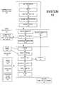
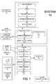
- FIG. 1shows a process flow diagram of the ozone cleaning system that produces and distributes the aqueous solution of ozone
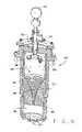
- FIG. 2shows a sectional view of the reaction vessel.
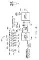
- FIG. 3shows a view of the compressed dry air supply skid.
- FIG. 4shows a view of the ozone generation skid.
- FIG. 5shows a view of the mixing skid.
- FIG. 6shows an alternative view of the reaction vessel.
- the methods described hereinreduce the bubble size of ozone gas in the aqueous ozone solution and the number of bubbles in the aqueous ozone solution.
- the methodsincreases the concentration of ozone in the aqueous ozone solution as well as its oxidation reduction potential to improve the cleaning and sanitizing capabilities of the aqueous ozone solution.
- the compositions of aqueous ozone solution described hereinhave less bubbles and smaller bubbles of ozone gas than conventional solutions. Decreasing the bubble size of the ozone gas also assists in maintaining a uniform concentration of ozone gas in the aqueous ozone solution and reducing off-gassing.
- the compositions of aqueous ozone solutionprovide for cleaning and sanitizing of industrial facilities.
- Fresh water and the first aqueous ozone solutionare mixed to form the second aqueous ozone solution.
- the reaction vessel 350circulates the fresh water and forms a vortex, which mixes with the first aqueous ozone solution.
- the mixing in the reaction vessel 350 of the water and the first aqueous ozone solutionbreaks the ozone gas bubbles in the first aqueous ozone solution into smaller and smaller bubbles and forms the second aqueous ozone solution that exits the reaction vessel 350 .
- the first aqueous ozone solutionis forced into a saturated aqueous ozone solution having an ozone concentration of up to approximately 20 ppm and an oxidation reaction potential of up to approximately 2.6. Off-gassing of ozone gas is reduced by the reaction vessel 350 , as many of the gas bubbles in the first aqueous ozone solution are crushed.
- the reaction vessel 350is in fluidic communication with a supply of the first aqueous ozone solution, e.g., a venturi 310 , in which the first aqueous ozone solution is formed by injection of ozone gas into water in the venturi 310 .
- the reaction vessel 350is also in fluidic communication with a supply of water 330 for mixing with the first aqueous ozone solution. After the mixing in the reaction vessel 350 , the reaction vessel 350 outputs the second aqueous ozone solution to a contact tank 405 .
- the reaction vessel 350comprises a conical-shaped surface 385 having a plurality of edges 380 on the conical-shaped surface 385 .
- the conical-shaped surface 385imparts a rotating action or a vortex to the water entering the reaction vessel 350 from the supply of water 330 , and the water rotates about the conical-shaped surface 385 toward the first aqueous ozone solution entering the reaction vessel 350 , which crushes ozone gas bubbles in the first aqueous ozone water solution.
- the system 10provides a centralized system for producing an aqueous ozone solution, i.e., the aqueous ozone solution is prepared and distributed from a central location in an industrial facility to different application points throughout the industrial facility.
- the system 10provides for the distribution of the aqueous ozone solution at different flow rates and at different concentrations to the different application points.
- the system 10monitors and maintains the ozone concentration and flow rate of the aqueous ozone solution at desired levels.
- the system 10provides a uniform and consistent aqueous ozone solution without off-gassing problems.
- Fluctuations in the concentration of ozone in the aqueous ozone solutionare kept to a minimum with the aid of monitoring systems that monitor the concentration of ozone in the aqueous ozone solution and modulate levels of ozone gas introduced into the aqueous ozone solution.
- the system 10increases the oxidation reaction potential of a conventional aqueous ozone solution by reducing the bubble size of ozone gas and minimizing the amount of bubbles of ozone in the aqueous ozone solution.
- a process flow diagram for the systemis shown in FIG. 1 .
- a control panel/central server 50comprising a programmable logic controller and user interface is in electrical communication with the components of the system 10 to operate, monitor, and direct the system 10 .
- the control panel/central server 50regulates the concentration of ozone in the ozonated water solution and the flow of ozonated water solution.
- the control panel/central server 50is in electrical communication with the various components, systems and assemblies of the system 10 to ensure that the desired flow and concentration of the ozonated water solution are maintained.
- the control panel/central server 50regulates the flow and amount of ozone gas that is entrained in the solution.
- the system 10produces high pressure and high volumes of the ozonated water solution to clean and sanitize industrial facilities.
- the system 10may be scaled depending upon the application, for example, the system 10 may provide lower volumes, e.g. 1 gallon per minute and higher volumes, e.g., 10,000 gallons per minute.
- Ozone gas for use with the system 10is produced from ambient air.
- An important feature of the system 10is that it ensures that a consistent supply of dried air is delivered to oxygen concentrators 160 , which produce essentially pure oxygen gas for ozone generation in ozone generators 240 , such that the system 10 provides a sufficient quantity of ozone gas with consistent quality.
- the consistent supply of dried airultimately assists in creating the consistent supply of the aqueous ozonated solution produced by the system 10 .
- the system 10draws in the ambient air to a compressed dry air supply skid 100 (shown in FIG. 3 ) comprising an air compressor 120 , a dryer 140 , a dew point monitor 150 , the oxygen concentrators 160 , and an oxygen storage tank 180 .
- the air compressor 120is in communication with the dryer 140 .
- the air compressor 120compresses the ambient air and delivers the compressed air to the dryer 140 .
- the compressed airis dried in the dryer 140 .
- the dryer 140is in communication with the dew point monitor 150 , which measures the dew point of air exiting the dryer 140 .
- a suitable dew point monitor 150is commercially available from Vaisala Instruments.
- the compressed and dried airpasses to the oxygen concentrators 160 , which produce essentially pure oxygen gas from the dried and compressed air that is stored in the oxygen storage tank 180 .
- the oxygen storage tank 180acts as a storage and supply reservoir of oxygen for ozone generation. Excess oxygen is stored in the oxygen storage tank.
- the oxygen concentrators 160may use a pressure swing adsorption process using a molecular sieve. A suitable oxygen concentrator 160 is commercially available from the AirSep Corporation.
- the compressed dry air supply skid 100may further include one or more filters 132 for oil and contaminant removal, one or more pressure indicators 134 for monitoring the pressures of the compressed air and the stored oxygen gas in the oxygen storage tank 180 , and one or more pressure relief valves 136 for discharging pressurized gas.
- a flow controller 138modulates the flow of oxygen gas from the oxygen concentrators 160 to the oxygen storage tank 180 , while one of the pressure indicators 134 and one of the pressure relief valves 136 is also employed to monitor and provide pressure relief for the oxygen gas directed to the oxygen storage tank 180 from the oxygen concentrators 160 .
- the essentially pure oxygen gasis delivered to an ozone generation skid 200 (shown in FIG. 4 ) comprising the ozone generator 240 , an ozone destruct unit 260 , a distribution manifold 270 , and one or more mass flow controllers 305 .
- the ozone generation skidproduces ozone and directs it via the distribution manifold 270 and the one or more mass flow controllers 305 to one or more mixing skids 300 (shown in FIG. 5 ).
- the ozone generator 240produces ozone gas from the essentially pure oxygen gas.
- the ozone generator 240is in communication with the oxygen storage tank 180 .
- the ozone generator 240is configured with a cooling system, such as a cool-water recirculation jacket 243 , to maintain the ozone generator 240 at under approximately 100° F.
- the ozone generatormay utilize a corona discharge method of ozone generation. Maintaining a cool temperature is preferred to regulate ozone concentration, as higher concentrations of ozone gas are achieved from the ozone generator 240 when the temperature of the ozone generator 240 is maintained at these cool levels.
- the ozone destruct unit 260receives excess ozone or ozone that has separated from the aqueous ozone solution in other parts of the system 10 for destruction.
- the ozone generation skid 200comprises one or more ozone generators 240 .
- Some of the one or more ozone generatorsmay only be used in a backup capacity, i.e., when one of the previously operational ozone generators 240 require maintenance or breaks-down. As such, the industrial facility will not need to shut down for a conventional cleaning process when one of the ozone generators 240 is non-operational.
- up to 30 or more ozone generators 240may be included in the ozone generation skid 200 .
- the ozone generators 240are in electrical communication with the control panel/central server 50 in order to monitor and control their operation.
- the ozone generation skid 200includes the distribution manifold 270 and the mass flow controllers 305 for disseminating the ozone gas to the one or more mixing skids 300 for mixing with water to produce the aqueous ozone solution.
- the distribution manifold 270is in communication with the ozone generators 240 .
- An isolation valve 242 , an air actuated ball valve 244 , and a back flow preventer 246are positioned between the ozone generator 240 and the distribution manifold 270 to direct the flow of ozone gas from the ozone generator 240 to the distribution manifold 270 .
- the mass flow controllers 305are in electrical communication with the control panel/central server 50 for modulating the flow of the ozone gas.
- a suitable mass flow controller 305is commercially available from Eldrige, Products, Inc.
- the distribution manifold 270will branch into separate lines each having a mass flow controller 305 a - g in communication with each of the one or more mixing skids 300 a - g .
- Additional isolation valves 242are configured between the mass flow controllers 305 a - g and the distribution manifold 270 .
- the number of mixing skids 300 a - g and mass flow controllers 305 a - gwill depend upon the application requirements of the system 10 .
- the distribution manifold 270further directs ozone gas to an auxiliary use, such as a deodorizer, or to the ozone destruction unit 260 .
- the one or more mixing skids 300comprise the venturi 310 , the reaction vessel 350 , the contact tank 405 , a degassing separator 420 , a demister 440 , a mixing ozone monitor 460 , and a pump 480 .
- water from the water supply 330 and ozone gas from the ozone generation skid 200are directed via lines, hoses, and/or piping to the venturi 310 for forming the first aqueous ozone solution.
- the venturi 310acts as an injector, i.e., it injects the ozone gas into the water.
- a preferred injectoris commercially available from the Mazzei Injector Corporation; however, any of a variety of injectors could be utilized in the one or more mixing skids 300 .
- the ozone gaspasses through the one or more mass flow controllers 305 a - g , which measures the flow of ozone to the venturi 310 and modulates the flow of ozone to the venturi 310 .
- the mass flow controllers 305 a - gare in electrical communication with the control panel/central server 50 in order regulate and control the flow of ozone gas through the mass flow controllers 305 a - g .
- the operator of the systemmay adjust the flow of ozone to the venturi 310 to obtain the desired ozone concentrations level in the aqueous ozone solution.
- the first aqueous ozone solutionis now directed to the reaction vessel 350 for further processing to reduce the bubble size of the ozone gas in the aqueous ozone solution and the number of bubbles and to increase the concentration of ozone in the aqueous ozone solution as well as its oxidation reduction potential. Decreasing the bubble size of the ozone gas also assists in maintaining a uniform concentration of ozone gas in the aqueous ozone solution.
- a supply of wateris in communication with the reaction vessel 350 . The supply of water directs water to a conical-shaped surface 385 of the reaction vessel 350 , and the water mixes with the first aqueous ozone solution to form the second aqueous ozone solution.
- the operation and structure of the reaction vessel 350will now be described in detail with reference to FIG. 2 .
- the first aqueous ozone solution from the venturi 310is discharged into the bottom of reaction vessel 350 at an inlet port 355 .
- the first aqueous ozone solutiontravels up an inner vortex assembly sleeve 370 in the interior of the reaction vessel 350 .
- Nozzles 360discharge a stream of fresh water, at approximately 50 to 55 psi, at the top of the reaction vessel 350 into the inner vortex assembly sleeve 370 .
- the fresh water from the nozzles 360dilutes the first aqueous ozone solution from the venturi 310 .
- the nozzles 360receive the fresh water from the water supply 330 through a fresh water inlet 345 and a regulator 348 .
- the regulator 348is in electrical communication with the control panel/central server 50 .
- the regulator 348provides pressure readings to the control panel/central server 50 , and the regulator 348 modulates the pressure and flow of fresh water into the inner vortex assembly sleeve 370 at the direction of the control panel/central server 50 .
- the inner vortex assembly sleeve 370is shown in FIG. 2 .
- the inner vortex assembly sleeve 370is under a pressure of approximately 50 psi to approximately 125 psi.
- the pressure in the inner vortex assembly sleeve 370is varied to accommodate the desired flow rate of the aqueous ozonated water solution from the particular mixing skid 300 a - g . If the pressure in the inner vortex assembly sleeve 370 is too high, then off-gassing problems of ozone gas may occur.
- the inner vortex assembly sleeve 370comprises the conical-shaped surface 385 .
- the first aqueous ozone solutionenters the bottom of the reaction vessel 350 at the inlet port 355 , while fresh water is discharged from nozzles 360 toward the entering first aqueous ozone solution.
- the first aqueous ozone solutionenters a cavity 358 , which acts as a reservoir to receive the first aqueous ozone solution.
- An opening 365separates the conical-shaped surface 385 from the cavity 358 .
- the opening 365is in fluidic communication with the cavity 358 and the inner vortex assembly sleeve 370 .
- the inner vortex assembly sleeve 370has a narrow diameter toward the inlet port 355 and the opening 365 and gradually increases in diameter toward an outlet 390 , which creates the conical-shaped surface 385 .
- the opening 365is at the narrowest point of the conical-shaped surface 385 .
- the nozzles 360direct the fresh water at the conical-shaped surface 385 .
- the nozzles 360direct the fresh water at the sloping surfaces of the conical-shaped surface 385 .
- the conical-shaped surfacehas sloping surfaces or sides leading to the opening 365 .
- the direction of the nozzles 360 and the conical-shaped surface 385imparts a rotating action or a vortex to the fresh water, and the fresh water rotates about the conical-shaped surface 385 toward the opening 365 .
- the second aqueous ozone solutionis formed by mixing the water with the first aqueous ozone solution.
- aqueous ozone solution from the cavity 358passes into a cone void 388 , which is the generally hollow central region of the inner vortex assembly sleeve 370 , as defined by the conical-shaped surface 385 .
- the inner vortex assembly sleeve 370comprises approximately 10 to approximately 50 of the edges 380 on the conical-shaped surface 385 .
- Each of the edges 380may comprise a generally perpendicular angle above and below the adjacent edge 380 .
- the edges 380form a stair-step like surface for the conical-shaped surface 385 .
- the edges 380surround a perimeter of the cone void 388 .
- the edges 380are in contact with the hollow interior, i.e., the cone void 388 .
- Other constructions, geometries, or surfaces on the conical-shaped surface 385may be employed to reduce the bubble size of the ozone gas.
- the conical-shaped surfacemay include a plurality of concentric ridges 382 on or about the conical-shaped surface 385 .
- the inner vortex assembly sleeve 370turns the first aqueous ozone solution, under high pressure, around and against the series of edges 380 or ridges 382 on the interior conical-shaped surface 385 of the inner vortex assembly sleeve 370 .
- the interaction of the fresh water, the first aqueous ozone solution, and the edges 380crush and break the ozone gas into smaller and smaller bubbles in the aqueous ozone solution, which exits the reaction vessel 350 as the second aqueous solution at the outlet 390 .
- Off-gassing of ozone gas into the cone void 388is re-mixed into the aqueous ozone solutions.
- the conical-shaped surface 385 and discharge of fresh water from the nozzles 360causes the fresh water to circulate and form a vortex which mixes with the first aqueous ozone solution passing through the inner vortex assembly sleeve 370 and eventually exiting at the outlet 390 as the second aqueous solution.
- the sleeve 370is significant to cause the necessary break down of the microscopic bubbles of ozone gas and allows the maximum molar absorptivity of the ozone gas into the second aqueous solution.
- the aqueous ozone solutionis forced into a saturated aqueous ozone solution having an ozone concentration of up to approximately 20 ppm and an oxidation reaction potential of up to approximately 2.6. Breaking down the bubbles of ozone into smaller bubbles of ozone increases the oxidation reduction potential of the ozone in the aqueous ozone solution.
- the greater oxidation reduction potential of the aqueous ozone solution waterallows the ozone to act not only as a sanitizer, but as a degreaser and therefore has more oxidizing power than conventionally mixed solutions.
- the aqueous ozone solution entering the reaction vessel 350 at the inlet port 355 and the fresh water entering the reaction vesselforms a solution that is approximately 10% to approximately 20% fresh water, i.e., approximately 1 part by volume fresh water from the water supply is mixed with approximately 4 parts to approximately 9 parts by volume aqueous ozone solution from the inlet port 355 .
- the ORP value for the aqueous ozone solution exiting the outlet 390is approximately the same as the ORP value for the aqueous ozone solution entering the inlet 355 , despite the dilution of the aqueous ozone solution entering the inlet 355 by the fresh water from the nozzles 360 .
- the reaction vessel 350 and the inner vortex assembly sleevemay be made from stainless steel, metal alloys, or hard plastic materials, such as chlorinated Polyvinyl Chloride (CPVC).
- CPVCchlorinated Polyvinyl Chloride
- the aqueous ozone solutionis directed to the contact tank 405 and a degassing separator 420 in communication with the reaction vessel 350 .
- the contact tank 405should have a volume approximately twice the desired amount of volume of aqueous ozone solution. For example, if the mixing skid 300 a is providing 100 gallons/per minute in flow, then the contact tank 405 should have a capacity of approximately 200 gallons. As such, in this particular example, the solution is spending approximately two minutes in the contact tank 405 .
- the degassing separatoris important to remove the excess ozone bubbles from the aqueous ozone solution to reduce the levels of free ozone gas released at an application point during the spraying of the aqueous ozone solution, which in high concentrations could breach OSHA regulations.
- the separated gas bubblesare directed to a demister 440 , where a liquid component of the separated gas bubble is collected and drained, while an ozone gas component of the separated gas bubbles is directed from the demister 440 to the ozone destruction unit 260 .
- the aqueous ozone solution exiting the degassing separator 420passes through and the mixing ozone monitor 460 and on to one or more pumps 480 via piping, hosing and/or lines.
- the aqueous ozone solutionmay be directed to one or more of the pumps 480 which may pump the aqueous ozone solution at different flow rates and pressures from the mixing skid 300 .
- the aqueous ozone solutionis pumped from the mixing skid 300 via distribution piping/hosing 510 in communication with the pumps 480 to one or more applicators 530 for applying the aqueous ozone solution to the hard surfaces and other items for sanitation.
- the applicators 530include spray wands, nozzles, brushes, nebulizers, spray guns and the like, and various combinations thereof.
- Each applicator 530includes an applicator ozone monitor 550 .
- the concentration of the aqueous ozone solutionis monitored by the applicator ozone monitor 550 , which measures the exact concentration of ozone in the aqueous ozone solution exiting from the applicator 530 .
- the plant operatormay monitor and adjust the concentration of ozone in the aqueous ozone solution based on readings from the applicator ozone monitor 550 .
- the applicator ozone monitor 550is in electrical communication with the control panel/central server 50 . If the applicator ozone monitor 550 indicates that the levels of ozone in the aqueous ozone solution are too low, then the operator or automated systems in the control panel/central server 50 may adjust the mass flow controller 305 to increase the amount of ozone gas directed to the venturi 310 , such that concentration levels of ozone in the aqueous ozone solution at the applicator ozone monitor 550 are increased.
- the system 10may comprise one or mixing skids 300 with one or more pumps 480 supplying one or more applicators 530 .
- the one or more pumps 480may pump the aqueous ozone solution at different rates and at different concentrations to the different applicators 530 .
- the system 10may be customized, depending upon a specific industrial facility and its specific cleaning needs.
- the system 10may comprise a variety of high pressure and low pressure applicators 530 and with certain applicators applying different concentrations of aqueous ozone solution.
- the system 10provides an applied dosage of an aqueous ozone solution that is consistent over time in terms of the desired concentration and flow rate to the one or more applicators 530 .
- the control panel/central server 50in conjunction with the applicator ozone monitor 550 and mass flow controllers 305 , monitor and regulate the concentration and flow of the aqueous ozone solution.
- the reaction vessel 350is important to the mass transfer of ozone gas in the water, i.e., how the ozone gas is dissolved into the water to form the aqueous ozone solution.
- the system 10produces a saturated aqueous ozone solution having an ozone concentration of up to approximately 20 ppm.
- the reaction vessel 350helps reduce the number of bubbles and create the smallest possible bubbles of ozone in the second aqueous ozone solution in order to produce the saturated aqueous ozone solution with an ozone concentration of up to approximately 20 ppm and an oxidation reduction potential of 2.6.
- the amount of ozone dissolved into the waterdepends, in part, on the surface area of the gas/water interaction. The smaller the bubble, the better the mass transfer because one cubic inch of tiny bubbles has much more surface area than a single, one cubic inch bubble.
- the edges 380 on the inner vortex assembly sleeve 370assist in physically reducing the bubble size of the ozone gas. As the aqueous ozone solution is forced through the inner vortex assembly sleeve 370 , the bubbles of ozone contact the edges 380 and break into smaller and smaller bubbles. The smaller bubbles dissolving in the water help to saturate the aqueous ozone solution with ozone.
- the pressure, of approximately 50 psi to approximately 125 psi, applied in the reaction vessel 350also improves the mass transfer between the bubbles of ozone gas and the water.
- the higher the pressurethe more a “squeeze” is put on the transfer of gas bubbles into the water enhancing the process of dissolving the gas bubbles into the aqueous ozone solution and creating the saturated aqueous ozone solution.
- the higher pressurealso forces the gas bubbles against the edges 380 further breaking them down into smaller bubbles.
- the temperature of the wateris also an important consideration in the mass transfer process. At cooler temperatures, the ozone diffuses better in the water. At cooler water temperatures, the contact time between the ozone gas bubbles and the water in forming the aqueous ozone solution is reduced. In general, it is difficult for water to absorb a gas when the water is trying to become a gas.
- the water from the water supply 330should be at a temperature of approximately 33° F. to approximately 50° F.
- the concentration of the ozone gas in the carrier gasalso affects the mass transfer of the ozone gas in to the water. Higher concentrations of ozone in the carrier gas will result in higher concentrations of ozone being absorbed into the aqueous ozone solution. Corona discharge ozone generation equipment generally creates higher concentrations of ozone gas in the carrier gas than ultraviolet types of ozone generation.
- a nanobubbleis a bubble of gas having a diameter of approximately several hundred nanometers or below.
- the generation characteristics of ozone gas nanobubbles in aqueous solutionmay be changed by the dissolved ozone gas concentration in the water of the aqueous solution.
- the diameters, numbers, and concentration of nanobubblesmay be measured by light scattering methods.
- the aqueous ozone solution of ozone nanobubblesmay be used as cleaning agents both for the prevention of surface fouling and for the de-fouling of surfaces.
- the nanobubblesmay be used to remove proteins that are already adsorbed to a surface, as well as for the prevention of non-specific adsorption of proteins.
- the aqueous ozone solution of ozone nanobubblesmay be formed from the processes described herein in which the first aqueous ozone solution is formed and undergoes processing in the reaction vessel 350 and mixing with water to form the second aqueous ozone solution.
- the processing in the reaction vessel 350 and the mixing with water under pressurereduces the bubble size of the ozone gas into nanobubbles and maintains the ozone gas in the form of nanobubbles.
- the first aqueous ozone solutionis formed from the venturi 310 injecting ozone gas from the ozone generation skid 200 into water from the water supply 330 .
- the ozone gas in the first aqueous ozone solutionforms ozone gas bubbles of a variety of sizes, including macrobubbles of approximately 1 ⁇ 4 inch in diameter to approximately 1 inch in diameter. Such macrobubbles of ozone are prone to off-gassing during a cleaning or spraying application.
- the first aqueous ozone solutionis further processed to reduce the bubble size of the ozone gas.
- the first aqueous ozone solutionis directed to the reaction vessel 350 to reduce bubble size.
- the first aqueous ozone solutionis mixed with the pressurized water from the nozzles 360 .
- the macrobubbles of ozone gas in the first aqueous ozone solutionare crushed in the reaction vessel 350 against the conical-shaped surface 385 of the reaction vessel 350 by the vortex created by the incoming water from the nozzles 360 .
- the pressure from the incoming waterreduces the bubble size of the ozone gas and assists in maintaining the reduced bubble size.
- the pressurecauses the bubbles of ozone gas to shrink.
- the second aqueous ozone solutionis now formed from the mixing of the water and the first aqueous ozone solution in the reaction vessel 350 .
- the bubbles of the ozone gas in the second aqueous ozone solutionhave been reduced into nanobubbles.
- the nanobubblesare nano-sized, ozone gas-containing cavities in the aqueous solution.
- Essentially all of the ozone gas in the second aqueous ozone solutionis contained in nanobubbles of ozone gas dissolved in the second aqueous ozone solution.
- the ozone gases in the second ozone solutionincludes ozone gas bubbles or nanobubbles of approximately 15 nanometers in diameter to approximately 600 nanometers in diameter.
- the second ozone solutionincludes ozone gas bubbles of approximately 50 nanometers in diameter to approximately 200 nanometers in diameter.
- the ozone gas bubbleshave a wall thickness of approximately 2 nanometers to approximately 60 nanometers.
- the second ozone solutionincludes ozone gas bubbles having a wall thickness of approximately 5 nanometers in diameter to approximately 20 nanometers in diameter.
- the charge density at the surface of the ozone gas bubblesincreases as the nanobubbles shrink.
- the increased charge density at the surface of the nanobubblespromotes self-organization.
- the increase in charge densitypromotes longer life and slower diffusion for the ozone gas nanobubbles.
- the nanobubblesform a surface tension, which provides for the nanobubbles to adhere to each other.
- a contact surfacesuch as a work surface or other food preparation surface
- the adherence between the nanobubblesprovides stability and creates a blanket or layer of nanobubbles on the contact surface.
- the nanobubbleslast longer than conventional aqueous ozone solutions.
- the nanobubblesstop protein from adhering to the contact surface.
- the nanobubblesremove and prevents bio-fouling
- the ozone gas solutioncreates a film, layer or blanket of nanobubbles that may last for several hours to several days on the contact surface.
- the nanobubbles of ozone gascreates a uniform, dense and longer lasting coating of an aqueous ozone solution.
- the use of nanobubbles on the contact surfaceprovides an antibacterial layer on the contact surface, which reduces the risk of surface contamination or bio-fouling.
- the system 10produces an aqueous ozone solution to attack and destroy pathogens and act as a no-rinse sanitizer for hard surfaces in a variety of applications, especially industrial processing facilities related to food processing.
- the solution of aqueous ozoneis applied at high pressure to the hard surfaces, and is effective for the removal of soils and bulk materials from the hard surfaces. When applied at high pressure, the solution penetrates the soils and oxides of the biofilm that acts as the bond or glue that allows the soils and oxides to attach themselves to the hard surfaces.
- the system 10is designed to be the first totally chemical free system to destroy the biofilm on conveyors systems and hard surfaces during food processing production allowing for continuous or extended production.
- the solution discharges from the assemblythe solution could be channeled into both a high pressure stream as well as a low pressure stream.
- the high-pressure stream of aqueous ozone solutionmay be better suited for cleaning and sterilizing highly soiled hard surfaces due to the extra force supplied by the high pressure aqueous ozone solution which will help destroy the biofilm adhering the soils to the hard surfaces.
- the low pressure aqueous ozone solutionmay be suited for the continuous sanitization of hard surface or application to a food item.
- the ozone produced by the ozone generator 240uses a high electrical discharge called “corona discharge” or “CD”. This method is most commonly used to generate usable amounts of ozone for most water treatment applications. Corona discharge creates a small, controlled lightning storm, which involves producing a constant, controlled spark (corona) across an air gap through which a prepared feed gas is passed. This feed gas may be air that has simply had most of its moisture removed or air with enhanced oxygen levels.
- An important aspect of using the corona discharge methods of ozone productionis ensuring that feed gas is dried at the dryer 140 to a dew point of at least approximately ⁇ 60 F.
- a properly installed and operated system 10poses no health hazards. While ozone is a toxic gas and the established concentration limits must be adhered to, the odor threshold of 0.01 ppm is far below the safety limit of 0.1 ppm exposure over an eight hour period. The first symptoms of excessive ozone exposure are headaches, eye, nose or throat irritation or a shortness of breath. These symptoms can be relieved by the simple application of fresh air. While no deaths have been reported from ozone, sound safety practices deserve attention. Ozone off-gas containment and destruction equipment for most water treatment applications is readily available and is usually a simple device containing either activated carbon or manganese dioxide.
- Ozoneis a much more powerful oxidizer than chlorine. Based on EPA charts of surface water CT values (disinfectant residual and time constant), chlorine CT values are nearly 100 times greater than ozone, meaning that ozone acts much more quickly than chlorine. Ozone creates none of the trihalomethanes commonly associated with chlorine compounds and properly matched to the application; ozone will reduce most organic compounds to carbon dioxide, water and a little heat. Finally, as ozone sheds the atom of the oxygen causing its molecular instability during the oxidation process, it becomes oxygen again.
- FIG. 10Facilities processing bottled water, perishable goods (meat, seafood, fruit, vegetables, etc.) are examples of ideal applications for the system 10 .
- ozoneefficiently oxidizes the organics that cause taste, odor, and color problems without leaving a high residual helps to simplify many water treatment.
- the lack of residual from ozone cleaning and sanitationalso makes ozone perfect for pre- and post-treatment processes in wash pad recycle systems, where the use of a chlorine compound would contribute to pH control or off gas problems.
- ozoneoxidizes and precipitates many metals and destroys some pesticides without leaving a trace.
- ozonefunctions as a preoxidizer of iron, manganese and sulfide compounds, allowing for their removal by simple direct filtration. Ozone acts quickly and easily, and the water quality resulting from its use is unmatched.
Landscapes
- Chemical & Material Sciences (AREA)
- Chemical Kinetics & Catalysis (AREA)
- Health & Medical Sciences (AREA)
- Life Sciences & Earth Sciences (AREA)
- Engineering & Computer Science (AREA)
- General Chemical & Material Sciences (AREA)
- Wood Science & Technology (AREA)
- Organic Chemistry (AREA)
- Oil, Petroleum & Natural Gas (AREA)
- Inorganic Chemistry (AREA)
- Epidemiology (AREA)
- Animal Behavior & Ethology (AREA)
- General Health & Medical Sciences (AREA)
- Public Health (AREA)
- Veterinary Medicine (AREA)
- Nanotechnology (AREA)
- Treatment Of Water By Oxidation Or Reduction (AREA)
- Cleaning By Liquid Or Steam (AREA)
Abstract
Description
Claims (14)
Priority Applications (1)
| Application Number | Priority Date | Filing Date | Title |
|---|---|---|---|
| US12/468,952US8735337B2 (en) | 2007-03-13 | 2009-05-20 | Aqueous ozone solution for ozone cleaning system |
Applications Claiming Priority (3)
| Application Number | Priority Date | Filing Date | Title |
|---|---|---|---|
| US89447607P | 2007-03-13 | 2007-03-13 | |
| US12/047,498US8071526B2 (en) | 2007-03-14 | 2008-03-13 | Aqueous ozone solution for ozone cleaning system |
| US12/468,952US8735337B2 (en) | 2007-03-13 | 2009-05-20 | Aqueous ozone solution for ozone cleaning system |
Related Parent Applications (1)
| Application Number | Title | Priority Date | Filing Date |
|---|---|---|---|
| US12/047,498Continuation-In-PartUS8071526B2 (en) | 2007-03-13 | 2008-03-13 | Aqueous ozone solution for ozone cleaning system |
Publications (2)
| Publication Number | Publication Date |
|---|---|
| US20090233839A1 US20090233839A1 (en) | 2009-09-17 |
| US8735337B2true US8735337B2 (en) | 2014-05-27 |
Family
ID=41063711
Family Applications (1)
| Application Number | Title | Priority Date | Filing Date |
|---|---|---|---|
| US12/468,952Active2029-02-06US8735337B2 (en) | 2007-03-13 | 2009-05-20 | Aqueous ozone solution for ozone cleaning system |
Country Status (1)
| Country | Link |
|---|---|
| US (1) | US8735337B2 (en) |
Cited By (2)
| Publication number | Priority date | Publication date | Assignee | Title |
|---|---|---|---|---|
| US11904366B2 (en) | 2019-03-08 | 2024-02-20 | En Solución, Inc. | Systems and methods of controlling a concentration of microbubbles and nanobubbles of a solution for treatment of a product |
| US12251669B2 (en) | 2021-04-16 | 2025-03-18 | En Solución | Shear flow nanobubble generator |
Families Citing this family (14)
| Publication number | Priority date | Publication date | Assignee | Title |
|---|---|---|---|---|
| US8735337B2 (en) | 2007-03-13 | 2014-05-27 | Food Safety Technology, Llc | Aqueous ozone solution for ozone cleaning system |
| US9068149B2 (en)* | 2007-03-14 | 2015-06-30 | Food Safety Technology, Llc | Ozone cleaning system |
| US20110030730A1 (en)* | 2008-03-13 | 2011-02-10 | Lynn Daniel W | System for producing and distributing an ozonated fluid |
| US9174845B2 (en) | 2008-07-24 | 2015-11-03 | Food Safety Technology, Llc | Ozonated liquid dispensing unit |
| US9522348B2 (en)* | 2008-07-24 | 2016-12-20 | Food Safety Technology, Llc | Ozonated liquid dispensing unit |
| WO2013025660A1 (en)* | 2011-08-13 | 2013-02-21 | Eco-Safe Systems Usa, Inc | Portable ozone disinfection system |
| CA2896332C (en) | 2013-01-17 | 2020-02-18 | Food Safety Technology, Llc | Ozonated liquid dispensing unit |
| CN104043352B (en)* | 2014-05-28 | 2016-03-30 | 宁波惠士康健康科技有限公司 | Blue oxygen (O 3) water manufacture sterilizing unit |
| US9492580B2 (en)* | 2014-07-24 | 2016-11-15 | Eliyahu DAVID | System and method for the safe provision of ozone |
| US9278153B1 (en)* | 2015-03-30 | 2016-03-08 | Chun Hung Tsang | Pesticide-free agricultural air sterilization and farming equipment |
| US10342246B2 (en) | 2016-09-09 | 2019-07-09 | Quail Systems, Llc | Ozone generator, system, and methods for retrofit of enclosed and air-conditioned environments |
| US20230276793A1 (en)* | 2020-03-18 | 2023-09-07 | Virginia Tech Intellectual Properties, Inc. | Method to develop engineered nanobubbles for sanitation |
| US12018859B2 (en) | 2021-06-15 | 2024-06-25 | Tennessee Innovative Products, Llc | Scalable ozone generator systems and methods for retrofit of ducted HVAC systems |
| WO2025183570A1 (en)* | 2024-03-01 | 2025-09-04 | Nanobubble Agritech Limited | Nanobubble generation system |
Citations (82)
| Publication number | Priority date | Publication date | Assignee | Title |
|---|---|---|---|---|
| US4035657A (en) | 1975-12-24 | 1977-07-12 | Murray J. Guy | Ozone generator |
| US4176061A (en) | 1978-03-06 | 1979-11-27 | Karel Stopka | Apparatus and method for treatment of fluid with ozone |
| US4352740A (en) | 1980-02-08 | 1982-10-05 | Linde Aktiengesellschaft | Water ozonation method |
| US4517159A (en) | 1983-07-05 | 1985-05-14 | Karlson Eskil L | Sterilizer |
| US4686036A (en) | 1983-06-20 | 1987-08-11 | Laederach Zaugg Barbara | Device for ozonizing a fluid |
| US4801310A (en) | 1986-05-09 | 1989-01-31 | Bielefeldt Ernst August | Vortex chamber separator |
| US4849237A (en) | 1987-10-30 | 1989-07-18 | Hurst William D | Method for sanitizing poultry carcasses in a poultry processing plant utilizing ozonated water |
| US4900481A (en) | 1987-10-29 | 1990-02-13 | Takashi Kishioka | Ozonic bubble water generator |
| US4963269A (en) | 1986-12-26 | 1990-10-16 | Mitsubishi Denki Kabushiki Kaisha | Water ozonization method |
| US5069880A (en) | 1990-05-07 | 1991-12-03 | Karlson Eskil L | Ozone sterilizer |
| US5174905A (en) | 1992-04-23 | 1992-12-29 | Donald Shaw | Apparatus and method for treating water with ozone |
| US5186841A (en) | 1991-11-05 | 1993-02-16 | Praxair Technology Inc. | Cooling water ozonation system |
| US5207237A (en) | 1990-07-20 | 1993-05-04 | Kew Import/Export Inc. | Ozoneated liquid system |
| US5213773A (en) | 1990-08-31 | 1993-05-25 | Burris William A | Treatment of liquid on demand |
| US5236512A (en) | 1991-08-14 | 1993-08-17 | Thiokol Corporation | Method and apparatus for cleaning surfaces with plasma |
| US5411713A (en) | 1991-07-03 | 1995-05-02 | I.T.M. Corporation | Ozone generating apparatus |
| US5431861A (en)* | 1993-03-15 | 1995-07-11 | Jinzo Nagahiro | Method of and apparatus for producing a high concentration ozone water solution |
| US5493754A (en) | 1994-12-13 | 1996-02-27 | U.S. Products, Inc. | Fabric cleaner with ozone injection |
| US5503808A (en) | 1993-12-27 | 1996-04-02 | Ozact, Inc. | Portable integrated ozone generator |
| US5556200A (en) | 1994-02-07 | 1996-09-17 | Kvaerner Pulping Technologies Aktiebolag | Apparatus for mixing a first fluid into a second fluid using a wedge-shaped, turbulence-inducing flow restriction in the mixing zone |
| US5641456A (en) | 1995-09-13 | 1997-06-24 | Marco Equipment Distributors, Inc. | Apparatus and method for cleaning |
| US5645797A (en) | 1993-07-14 | 1997-07-08 | Anglian Water Services, Ltd. | Method and apparatus for gas/liquid contact |
| US5670094A (en) | 1995-01-30 | 1997-09-23 | Ebara Corporation | Method of and apparatus for producing ozonized water |
| US5720905A (en) | 1996-12-18 | 1998-02-24 | Liu Chang International Co., Ltd. | Cleaning apparatus with ozone and bubble generating means |
| US5815869A (en) | 1996-03-18 | 1998-10-06 | Venturi Technology Enterprises, Inc. | Apparatus and method for cleaning carpets and fabrics |
| US5816498A (en) | 1996-12-04 | 1998-10-06 | Ozone Technologies, Inc. | Ozonation system for agricultural crop and field sprayer |
| US5824243A (en) | 1997-02-12 | 1998-10-20 | Contreras; Edward M. | Water ozonating system |
| US5824274A (en) | 1996-10-16 | 1998-10-20 | Long; Ron | Ozone treatment system for point of use purification of water and sanitizing agent for surfaces, articles and foods |
| US5839155A (en) | 1996-06-06 | 1998-11-24 | Cfr Corporation | Continuous flow cleaning system with ozone injection |
| US5863128A (en) | 1997-12-04 | 1999-01-26 | Mazzei; Angelo L. | Mixer-injectors with twisting and straightening vanes |
| US5865995A (en) | 1997-04-02 | 1999-02-02 | Nelson; William R. | System for treating liquids with a gas |
| US5914089A (en) | 1993-02-02 | 1999-06-22 | Masao Suzuki | Method of sterilization and disinfection by ozone |
| US5951921A (en) | 1997-01-31 | 1999-09-14 | Core Corporation | Apparatus for producing ozone water |
| US6030586A (en) | 1998-10-30 | 2000-02-29 | Kuan; Yu-Hung | Ozone generating and ozone/water mixing apparatus |
| US6039815A (en) | 1996-03-27 | 2000-03-21 | Alps Electric Co., Ltd. | Cleaning method and apparatus for the same |
| US6076808A (en) | 1996-04-30 | 2000-06-20 | Porter; Brooks S. | Apparatus for producing ozonated water |
| US6106731A (en) | 1998-10-05 | 2000-08-22 | Hayes; Charles R. | System and method for ozonating water for animal houses |
| US6115862A (en) | 1995-11-30 | 2000-09-12 | Cyclo3Pss Textile Systems, Inc. | Cold water ozone disinfection |
| US6153151A (en) | 1997-05-08 | 2000-11-28 | Moxley; Douglas A. | System and method for generating ozonated water |
| US6207064B1 (en) | 1999-07-12 | 2001-03-27 | Joseph Gargas | Ozone contact chamber |
| US6250324B1 (en) | 1994-11-04 | 2001-06-26 | Wayne Ernest Conrad | In-line venturi |
| US6274053B1 (en) | 2000-06-16 | 2001-08-14 | Fantom Technologies Inc. | Ozonation process |
| US6276304B1 (en) | 1998-10-13 | 2001-08-21 | Paul Ling Tai | Ozone injection system |
| US6348227B1 (en) | 1996-09-10 | 2002-02-19 | Boc Group, Inc. | Method of reducing microbial growth during processing of animal carcasses |
| US6361688B1 (en) | 1997-04-02 | 2002-03-26 | William R. Nelson | Treating a liquid with a gas |
| US6455017B1 (en) | 1999-02-04 | 2002-09-24 | John R. Kasting, Jr. | Method and mobile apparatus for washdown and sanitizing |
| US6458398B1 (en) | 1999-10-18 | 2002-10-01 | Eco Pure Food Safety Systems, Inc. | Cold water disinfection of foods |
| US6458257B1 (en) | 1999-02-09 | 2002-10-01 | Lynntech International Ltd | Microorganism control of point-of-use potable water sources |
| US6464210B1 (en) | 2002-03-22 | 2002-10-15 | Agrimond, Llc | Fluid dissolution apparatus |
| US6499671B1 (en) | 2000-09-01 | 2002-12-31 | Del Industries, Inc. | Ozone systems and methods for agricultural applications |
| US6517731B2 (en) | 2000-06-16 | 2003-02-11 | Fantom Technologies Inc. | Ozonation process |
| US20030049164A1 (en) | 2001-08-29 | 2003-03-13 | Bon Paulo Sergio | In-line system for ozone sanitation |
| US6585898B1 (en) | 1998-03-09 | 2003-07-01 | Otre Ab | Method and apparatus for preparation and use of ozone water |
| US20030173309A1 (en)* | 2000-08-18 | 2003-09-18 | Se-Ham Kim | Process for producing ozone-containing sterilizing water and an apparatus used therefor |
| US6638364B2 (en) | 2000-09-08 | 2003-10-28 | Electric Aquagenics Unlimited | System to clean and disinfect carpets, fabrics, and hard surfaces using electrolyzed alkaline water produced from a solution of NaCl |
| JP2003320232A (en)* | 2002-04-30 | 2003-11-11 | Shunsuke Hosokawa | Ozone water generator |
| US6649052B2 (en) | 2000-01-04 | 2003-11-18 | Iei Co., Ltd. | Ozone oxidizing apparatus |
| US6755977B2 (en) | 2002-06-19 | 2004-06-29 | Dennis A. Brunsell | Method in treating aqueous waste feedstream for improving the flux rates, cleaning and the useful life of filter media |
| US6808637B2 (en) | 2002-03-29 | 2004-10-26 | Dong Woo Kiyoun Inc. | System for producing ozone water and control method thereof |
| US6817541B2 (en) | 2000-09-01 | 2004-11-16 | Del Industries, Inc. | Ozone systems and methods for agricultural applications |
| CA2491781A1 (en) | 2004-01-09 | 2005-07-09 | Ozone International Llc | Cleaning and sanitizing system |
| US6948504B2 (en) | 2000-09-01 | 2005-09-27 | Mks Instruments, Inc. | Ozonated water flow and concentration control method |
| US20050214159A1 (en) | 2004-02-24 | 2005-09-29 | Schwei Mark C | Cart sanitizing system |
| US6962654B2 (en) | 2001-06-12 | 2005-11-08 | Hydrotreat, Inc. | Methods and apparatus for supplying high concentrations of dissolved oxygen and ozone for chemical and biological processes |
| US6964739B2 (en) | 2000-12-12 | 2005-11-15 | Tersano Inc. | Device and method for generating and applying ozonated water |
| US6991685B2 (en) | 2003-03-21 | 2006-01-31 | Ecolab Inc. | Low temperature cleaning |
| US7022225B1 (en) | 2003-04-18 | 2006-04-04 | Del Industries, Inc. | Water ozonation mixing and degassing system |
| US7108781B2 (en) | 2002-02-26 | 2006-09-19 | Usfilter Corporation | Enhanced air and water purification using continuous breakpoint halogenation with free oxygen radicals |
| US7255332B2 (en) | 2004-05-25 | 2007-08-14 | The Board Of Trustees Of The University Of Arkansas | System and method for dissolving gases in liquids |
| US20070189972A1 (en) | 2004-03-05 | 2007-08-16 | Reo Laboratory Co., Ltd | Method of forming nanobubbles |
| US20070199581A1 (en) | 2004-01-09 | 2007-08-30 | Ozone International Llc | Cleaning and sanitizing system |
| US7264680B2 (en) | 1997-05-09 | 2007-09-04 | Semitool, Inc. | Process and apparatus for treating a workpiece using ozone |
| US20070205161A1 (en)* | 2004-03-05 | 2007-09-06 | Kaneo Chiba | Ozone Water And Production Method Therefor |
| US7272947B2 (en) | 2004-09-03 | 2007-09-25 | Everest Water, Ltd. | Water producing method and apparatus |
| US7275982B1 (en) | 2006-05-12 | 2007-10-02 | Ozone International, Llc | Ozone-based conveyor cleaning system |
| US7276168B2 (en) | 2003-11-28 | 2007-10-02 | Siltronic Ag | Method for supply of constant-concentration ozonated water |
| US20070286795A1 (en) | 2004-03-08 | 2007-12-13 | Masayoshi Takahashi | Oxygen Nanobubble Water and Method of Producing the Same |
| US20080227680A1 (en) | 2007-03-14 | 2008-09-18 | Food Safety Technology, Llc | Aqueous ozone solution for ozone cleaning system |
| US20090032473A1 (en) | 2007-07-31 | 2009-02-05 | Shuji Ueki | Method of removing ozone remaining in water |
| US20090233839A1 (en) | 2007-03-13 | 2009-09-17 | Lynn Daniel W | Aqueous ozone solution for ozone cleaning system |
| US20100010422A1 (en)* | 2005-09-23 | 2010-01-14 | Sadatoshi Watanabe | Nanofluid Production Apparatus and Method |
| US20100021598A1 (en) | 2008-07-24 | 2010-01-28 | Lynn Daniel W | Ozonated liquid dispensing unit |
- 2009
- 2009-05-20USUS12/468,952patent/US8735337B2/enactiveActive
Patent Citations (90)
| Publication number | Priority date | Publication date | Assignee | Title |
|---|---|---|---|---|
| US4035657A (en) | 1975-12-24 | 1977-07-12 | Murray J. Guy | Ozone generator |
| US4176061A (en) | 1978-03-06 | 1979-11-27 | Karel Stopka | Apparatus and method for treatment of fluid with ozone |
| US4352740A (en) | 1980-02-08 | 1982-10-05 | Linde Aktiengesellschaft | Water ozonation method |
| US4352740B1 (en) | 1980-02-08 | 1986-04-22 | ||
| US4686036A (en) | 1983-06-20 | 1987-08-11 | Laederach Zaugg Barbara | Device for ozonizing a fluid |
| US4517159A (en) | 1983-07-05 | 1985-05-14 | Karlson Eskil L | Sterilizer |
| US4801310A (en) | 1986-05-09 | 1989-01-31 | Bielefeldt Ernst August | Vortex chamber separator |
| US4963269A (en) | 1986-12-26 | 1990-10-16 | Mitsubishi Denki Kabushiki Kaisha | Water ozonization method |
| US4900481A (en) | 1987-10-29 | 1990-02-13 | Takashi Kishioka | Ozonic bubble water generator |
| US4849237A (en) | 1987-10-30 | 1989-07-18 | Hurst William D | Method for sanitizing poultry carcasses in a poultry processing plant utilizing ozonated water |
| US5069880A (en) | 1990-05-07 | 1991-12-03 | Karlson Eskil L | Ozone sterilizer |
| US5207237A (en) | 1990-07-20 | 1993-05-04 | Kew Import/Export Inc. | Ozoneated liquid system |
| US5213773A (en) | 1990-08-31 | 1993-05-25 | Burris William A | Treatment of liquid on demand |
| US5411713A (en) | 1991-07-03 | 1995-05-02 | I.T.M. Corporation | Ozone generating apparatus |
| US5236512A (en) | 1991-08-14 | 1993-08-17 | Thiokol Corporation | Method and apparatus for cleaning surfaces with plasma |
| US5186841A (en) | 1991-11-05 | 1993-02-16 | Praxair Technology Inc. | Cooling water ozonation system |
| US5174905A (en) | 1992-04-23 | 1992-12-29 | Donald Shaw | Apparatus and method for treating water with ozone |
| US5914089A (en) | 1993-02-02 | 1999-06-22 | Masao Suzuki | Method of sterilization and disinfection by ozone |
| US5431861A (en)* | 1993-03-15 | 1995-07-11 | Jinzo Nagahiro | Method of and apparatus for producing a high concentration ozone water solution |
| US5645797A (en) | 1993-07-14 | 1997-07-08 | Anglian Water Services, Ltd. | Method and apparatus for gas/liquid contact |
| US5503808A (en) | 1993-12-27 | 1996-04-02 | Ozact, Inc. | Portable integrated ozone generator |
| US5556200A (en) | 1994-02-07 | 1996-09-17 | Kvaerner Pulping Technologies Aktiebolag | Apparatus for mixing a first fluid into a second fluid using a wedge-shaped, turbulence-inducing flow restriction in the mixing zone |
| US6250324B1 (en) | 1994-11-04 | 2001-06-26 | Wayne Ernest Conrad | In-line venturi |
| US5493754A (en) | 1994-12-13 | 1996-02-27 | U.S. Products, Inc. | Fabric cleaner with ozone injection |
| US5670094A (en) | 1995-01-30 | 1997-09-23 | Ebara Corporation | Method of and apparatus for producing ozonized water |
| US5641456A (en) | 1995-09-13 | 1997-06-24 | Marco Equipment Distributors, Inc. | Apparatus and method for cleaning |
| US6115862A (en) | 1995-11-30 | 2000-09-12 | Cyclo3Pss Textile Systems, Inc. | Cold water ozone disinfection |
| US5815869A (en) | 1996-03-18 | 1998-10-06 | Venturi Technology Enterprises, Inc. | Apparatus and method for cleaning carpets and fabrics |
| US6039815A (en) | 1996-03-27 | 2000-03-21 | Alps Electric Co., Ltd. | Cleaning method and apparatus for the same |
| US6076808A (en) | 1996-04-30 | 2000-06-20 | Porter; Brooks S. | Apparatus for producing ozonated water |
| US5839155A (en) | 1996-06-06 | 1998-11-24 | Cfr Corporation | Continuous flow cleaning system with ozone injection |
| US6348227B1 (en) | 1996-09-10 | 2002-02-19 | Boc Group, Inc. | Method of reducing microbial growth during processing of animal carcasses |
| US5824274A (en) | 1996-10-16 | 1998-10-20 | Long; Ron | Ozone treatment system for point of use purification of water and sanitizing agent for surfaces, articles and foods |
| US5816498A (en) | 1996-12-04 | 1998-10-06 | Ozone Technologies, Inc. | Ozonation system for agricultural crop and field sprayer |
| US5720905A (en) | 1996-12-18 | 1998-02-24 | Liu Chang International Co., Ltd. | Cleaning apparatus with ozone and bubble generating means |
| US5951921A (en) | 1997-01-31 | 1999-09-14 | Core Corporation | Apparatus for producing ozone water |
| US5824243A (en) | 1997-02-12 | 1998-10-20 | Contreras; Edward M. | Water ozonating system |
| US6361688B1 (en) | 1997-04-02 | 2002-03-26 | William R. Nelson | Treating a liquid with a gas |
| US5865995A (en) | 1997-04-02 | 1999-02-02 | Nelson; William R. | System for treating liquids with a gas |
| US6153151A (en) | 1997-05-08 | 2000-11-28 | Moxley; Douglas A. | System and method for generating ozonated water |
| US7264680B2 (en) | 1997-05-09 | 2007-09-04 | Semitool, Inc. | Process and apparatus for treating a workpiece using ozone |
| US5863128A (en) | 1997-12-04 | 1999-01-26 | Mazzei; Angelo L. | Mixer-injectors with twisting and straightening vanes |
| US6585898B1 (en) | 1998-03-09 | 2003-07-01 | Otre Ab | Method and apparatus for preparation and use of ozone water |
| US6106731A (en) | 1998-10-05 | 2000-08-22 | Hayes; Charles R. | System and method for ozonating water for animal houses |
| US6276304B1 (en) | 1998-10-13 | 2001-08-21 | Paul Ling Tai | Ozone injection system |
| US6030586A (en) | 1998-10-30 | 2000-02-29 | Kuan; Yu-Hung | Ozone generating and ozone/water mixing apparatus |
| US6455017B1 (en) | 1999-02-04 | 2002-09-24 | John R. Kasting, Jr. | Method and mobile apparatus for washdown and sanitizing |
| US6458257B1 (en) | 1999-02-09 | 2002-10-01 | Lynntech International Ltd | Microorganism control of point-of-use potable water sources |
| US6207064B1 (en) | 1999-07-12 | 2001-03-27 | Joseph Gargas | Ozone contact chamber |
| US6458398B1 (en) | 1999-10-18 | 2002-10-01 | Eco Pure Food Safety Systems, Inc. | Cold water disinfection of foods |
| US6649052B2 (en) | 2000-01-04 | 2003-11-18 | Iei Co., Ltd. | Ozone oxidizing apparatus |
| US6274053B1 (en) | 2000-06-16 | 2001-08-14 | Fantom Technologies Inc. | Ozonation process |
| US6517731B2 (en) | 2000-06-16 | 2003-02-11 | Fantom Technologies Inc. | Ozonation process |
| US20030173309A1 (en)* | 2000-08-18 | 2003-09-18 | Se-Ham Kim | Process for producing ozone-containing sterilizing water and an apparatus used therefor |
| US7264006B2 (en) | 2000-09-01 | 2007-09-04 | Mks Instruments, Inc. | Ozonated water flow and concentration control apparatus and method |
| US6817541B2 (en) | 2000-09-01 | 2004-11-16 | Del Industries, Inc. | Ozone systems and methods for agricultural applications |
| US6499671B1 (en) | 2000-09-01 | 2002-12-31 | Del Industries, Inc. | Ozone systems and methods for agricultural applications |
| US6948504B2 (en) | 2000-09-01 | 2005-09-27 | Mks Instruments, Inc. | Ozonated water flow and concentration control method |
| US6638364B2 (en) | 2000-09-08 | 2003-10-28 | Electric Aquagenics Unlimited | System to clean and disinfect carpets, fabrics, and hard surfaces using electrolyzed alkaline water produced from a solution of NaCl |
| US6964739B2 (en) | 2000-12-12 | 2005-11-15 | Tersano Inc. | Device and method for generating and applying ozonated water |
| US6962654B2 (en) | 2001-06-12 | 2005-11-08 | Hydrotreat, Inc. | Methods and apparatus for supplying high concentrations of dissolved oxygen and ozone for chemical and biological processes |
| US20030049164A1 (en) | 2001-08-29 | 2003-03-13 | Bon Paulo Sergio | In-line system for ozone sanitation |
| US7108781B2 (en) | 2002-02-26 | 2006-09-19 | Usfilter Corporation | Enhanced air and water purification using continuous breakpoint halogenation with free oxygen radicals |
| US6464210B1 (en) | 2002-03-22 | 2002-10-15 | Agrimond, Llc | Fluid dissolution apparatus |
| US6808637B2 (en) | 2002-03-29 | 2004-10-26 | Dong Woo Kiyoun Inc. | System for producing ozone water and control method thereof |
| JP2003320232A (en)* | 2002-04-30 | 2003-11-11 | Shunsuke Hosokawa | Ozone water generator |
| US6755977B2 (en) | 2002-06-19 | 2004-06-29 | Dennis A. Brunsell | Method in treating aqueous waste feedstream for improving the flux rates, cleaning and the useful life of filter media |
| US6991685B2 (en) | 2003-03-21 | 2006-01-31 | Ecolab Inc. | Low temperature cleaning |
| US7022225B1 (en) | 2003-04-18 | 2006-04-04 | Del Industries, Inc. | Water ozonation mixing and degassing system |
| US7276168B2 (en) | 2003-11-28 | 2007-10-02 | Siltronic Ag | Method for supply of constant-concentration ozonated water |
| US7087123B2 (en) | 2004-01-09 | 2006-08-08 | Ozone International Llc | Cleaning and sanitizing system |
| US7087124B2 (en) | 2004-01-09 | 2006-08-08 | Ozone International Llc | Cleaning and sanitizing system |
| US7188632B2 (en) | 2004-01-09 | 2007-03-13 | Ozone International Llc | Cleaning and sanitizing system |
| US7086407B2 (en) | 2004-01-09 | 2006-08-08 | Ozone International Llc | Cleaning and sanitizing system |
| CA2491781A1 (en) | 2004-01-09 | 2005-07-09 | Ozone International Llc | Cleaning and sanitizing system |
| US20070199581A1 (en) | 2004-01-09 | 2007-08-30 | Ozone International Llc | Cleaning and sanitizing system |
| US20050214159A1 (en) | 2004-02-24 | 2005-09-29 | Schwei Mark C | Cart sanitizing system |
| US20070205161A1 (en)* | 2004-03-05 | 2007-09-06 | Kaneo Chiba | Ozone Water And Production Method Therefor |
| US20070189972A1 (en) | 2004-03-05 | 2007-08-16 | Reo Laboratory Co., Ltd | Method of forming nanobubbles |
| US20070286795A1 (en) | 2004-03-08 | 2007-12-13 | Masayoshi Takahashi | Oxygen Nanobubble Water and Method of Producing the Same |
| US7255332B2 (en) | 2004-05-25 | 2007-08-14 | The Board Of Trustees Of The University Of Arkansas | System and method for dissolving gases in liquids |
| US7272947B2 (en) | 2004-09-03 | 2007-09-25 | Everest Water, Ltd. | Water producing method and apparatus |
| US20100010422A1 (en)* | 2005-09-23 | 2010-01-14 | Sadatoshi Watanabe | Nanofluid Production Apparatus and Method |
| US7275982B1 (en) | 2006-05-12 | 2007-10-02 | Ozone International, Llc | Ozone-based conveyor cleaning system |
| US20090233839A1 (en) | 2007-03-13 | 2009-09-17 | Lynn Daniel W | Aqueous ozone solution for ozone cleaning system |
| US20080227680A1 (en) | 2007-03-14 | 2008-09-18 | Food Safety Technology, Llc | Aqueous ozone solution for ozone cleaning system |
| US20090120473A1 (en) | 2007-03-14 | 2009-05-14 | Food Safety Technology, Llc | Ozone cleaning system |
| US20090008806A1 (en) | 2007-03-14 | 2009-01-08 | Food Safety Technology, Llc | Reaction vessel for an ozone cleaning system |
| US20090032473A1 (en) | 2007-07-31 | 2009-02-05 | Shuji Ueki | Method of removing ozone remaining in water |
| US20100021598A1 (en) | 2008-07-24 | 2010-01-28 | Lynn Daniel W | Ozonated liquid dispensing unit |
Non-Patent Citations (8)
| Title |
|---|
| International Search Report and Written Opinion for PCT/US08/56936 dated Jun. 3, 2008 (13 pages). |
| International Search Report and Written Opinion for PCT/US11/39711 dated Oct. 5, 2011 (9 pages). |
| International Search Report and Written Opinion for PCT/US2011/039756 dated Dec. 2, 2011 (11 pages). |
| Office Action for U.S. Appl. No. 12/047,498 dated Aug. 31, 2010 (13 pages). |
| Office Action for U.S. Appl. No. 12/179,335 dated Jun. 7, 2012 (11 pages). |
| Office Action for U.S. Appl. No. 12/179,335 dated Nov. 23, 2011 (12 pages). |
| Trevor C. Suslow, Oxidation Reduction Potential (ORP) for Water Disinfection Monitoring, Control and Documentation, University of California, Division of Agriculture and Natural Resources, 2004 (5 pages). |
| U.S. Appl. No. 13/310,108 Office Action mailed Sep. 25, 2013 (12 pages). |
Cited By (2)
| Publication number | Priority date | Publication date | Assignee | Title |
|---|---|---|---|---|
| US11904366B2 (en) | 2019-03-08 | 2024-02-20 | En Solución, Inc. | Systems and methods of controlling a concentration of microbubbles and nanobubbles of a solution for treatment of a product |
| US12251669B2 (en) | 2021-04-16 | 2025-03-18 | En Solución | Shear flow nanobubble generator |
Also Published As
| Publication number | Publication date |
|---|---|
| US20090233839A1 (en) | 2009-09-17 |
Similar Documents
| Publication | Publication Date | Title |
|---|---|---|
| US8071526B2 (en) | Aqueous ozone solution for ozone cleaning system | |
| US8735337B2 (en) | Aqueous ozone solution for ozone cleaning system | |
| US6499671B1 (en) | Ozone systems and methods for agricultural applications | |
| Summerfelt et al. | Review of ozone processes and applications as an oxidizing agent in aquaculture | |
| US6132629A (en) | Method and apparatus for continuous or intermittent supply of ozonated water | |
| US7695692B2 (en) | Apparatus and method for producing chlorine dioxide | |
| JP5878525B2 (en) | System for producing and dispensing ozonated fluids | |
| US20030150933A1 (en) | Ozone systems and methods for agricultural applications | |
| US7604780B2 (en) | Ozone disinfection apparatus | |
| US9603963B2 (en) | Method and apparatus for treating industrial gas streams and biological fouling | |
| US20090173697A1 (en) | Method and apparatus for the production and delivery of monochloramine into water streams | |
| US20080006586A1 (en) | Method and apparatus for the production and delivery of monochloramine into water streams | |
| US6716340B2 (en) | Water treatment system | |
| JP2005514201A (en) | Water supply system, in particular a method for sterilization and cleaning of a water supply system in swimming and bathing pool units, and apparatus for carrying out the same | |
| US7067017B2 (en) | Method and system for cleaning semiconductor elements | |
| US10646611B2 (en) | Methods and equipment for treating industrial gas streams and biological fouling | |
| AU2015202612A1 (en) | Ozone cleaning system | |
| AU2014201408A1 (en) | Ozone cleaning system | |
| CA2997487C (en) | Methods and equipment for treating industrial gas streams and biological fouling | |
| WO2007008543A2 (en) | Method and apparatus for the production and delivery of monochloramine into water streams | |
| HOCHHEIMER | Review of Ozone Processes and Applications As an Oxidizing Agent in Aquaculture STEVEN Tsummerfelt |
Legal Events
| Date | Code | Title | Description |
|---|---|---|---|
| AS | Assignment | Owner name:FOOD SAFETY TECHNOLOGY, LLC, NEBRASKA Free format text:ASSIGNMENT OF ASSIGNORS INTEREST;ASSIGNOR:LYNN, DANIEL W.;REEL/FRAME:022992/0192 Effective date:20090630 | |
| AS | Assignment | Owner name:FOOD SAFETY TECHNOLOGY, LLC, NEBRASKA Free format text:ASSIGNMENT OF ASSIGNORS INTEREST;ASSIGNOR:LYNN, DANIEL W.;REEL/FRAME:032775/0426 Effective date:20090630 | |
| STCF | Information on status: patent grant | Free format text:PATENTED CASE | |
| MAFP | Maintenance fee payment | Free format text:PAYMENT OF MAINTENANCE FEE, 4TH YR, SMALL ENTITY (ORIGINAL EVENT CODE: M2551) Year of fee payment:4 | |
| MAFP | Maintenance fee payment | Free format text:PAYMENT OF MAINTENANCE FEE, 8TH YR, SMALL ENTITY (ORIGINAL EVENT CODE: M2552); ENTITY STATUS OF PATENT OWNER: SMALL ENTITY Year of fee payment:8 | |
| AS | Assignment | Owner name:CC ACQUISITION CORP., MINNESOTA Free format text:ASSIGNMENT OF ASSIGNORS INTEREST;ASSIGNOR:FOOD SAFETY TECHNOLOGY, L.L.C.;REEL/FRAME:061526/0326 Effective date:20220929 | |
| AS | Assignment | Owner name:CLEANCORE SOLUTIONS, INC., NEBRASKA Free format text:CHANGE OF NAME;ASSIGNOR:CC ACQUISITION CORP.;REEL/FRAME:062609/0436 Effective date:20221122 | |
| MAFP | Maintenance fee payment | Free format text:PAYMENT OF MAINTENANCE FEE, 12TH YR, SMALL ENTITY (ORIGINAL EVENT CODE: M2553); ENTITY STATUS OF PATENT OWNER: SMALL ENTITY Year of fee payment:12 |