US8734522B2 - Posterior stabilized orthopaedic prosthesis - Google Patents
Posterior stabilized orthopaedic prosthesisDownload PDFInfo
- Publication number
- US8734522B2 US8734522B2US13/527,758US201213527758AUS8734522B2US 8734522 B2US8734522 B2US 8734522B2US 201213527758 AUS201213527758 AUS 201213527758AUS 8734522 B2US8734522 B2US 8734522B2
- Authority
- US
- United States
- Prior art keywords
- cam surface
- spine
- posterior
- flexion
- cam
- Prior art date
- Legal status (The legal status is an assumption and is not a legal conclusion. Google has not performed a legal analysis and makes no representation as to the accuracy of the status listed.)
- Active
Links
Images


Classifications
- A—HUMAN NECESSITIES
- A61—MEDICAL OR VETERINARY SCIENCE; HYGIENE
- A61F—FILTERS IMPLANTABLE INTO BLOOD VESSELS; PROSTHESES; DEVICES PROVIDING PATENCY TO, OR PREVENTING COLLAPSING OF, TUBULAR STRUCTURES OF THE BODY, e.g. STENTS; ORTHOPAEDIC, NURSING OR CONTRACEPTIVE DEVICES; FOMENTATION; TREATMENT OR PROTECTION OF EYES OR EARS; BANDAGES, DRESSINGS OR ABSORBENT PADS; FIRST-AID KITS
- A61F2/00—Filters implantable into blood vessels; Prostheses, i.e. artificial substitutes or replacements for parts of the body; Appliances for connecting them with the body; Devices providing patency to, or preventing collapsing of, tubular structures of the body, e.g. stents
- A61F2/02—Prostheses implantable into the body
- A61F2/30—Joints
- A61F2/38—Joints for elbows or knees
- A61F2/3886—Joints for elbows or knees for stabilising knees against anterior or lateral dislocations
- A—HUMAN NECESSITIES
- A61—MEDICAL OR VETERINARY SCIENCE; HYGIENE
- A61F—FILTERS IMPLANTABLE INTO BLOOD VESSELS; PROSTHESES; DEVICES PROVIDING PATENCY TO, OR PREVENTING COLLAPSING OF, TUBULAR STRUCTURES OF THE BODY, e.g. STENTS; ORTHOPAEDIC, NURSING OR CONTRACEPTIVE DEVICES; FOMENTATION; TREATMENT OR PROTECTION OF EYES OR EARS; BANDAGES, DRESSINGS OR ABSORBENT PADS; FIRST-AID KITS
- A61F2/00—Filters implantable into blood vessels; Prostheses, i.e. artificial substitutes or replacements for parts of the body; Appliances for connecting them with the body; Devices providing patency to, or preventing collapsing of, tubular structures of the body, e.g. stents
- A61F2/02—Prostheses implantable into the body
- A61F2/30—Joints
- A61F2/38—Joints for elbows or knees
- A61F2/3836—Special connection between upper and lower leg, e.g. constrained
- A—HUMAN NECESSITIES
- A61—MEDICAL OR VETERINARY SCIENCE; HYGIENE
- A61F—FILTERS IMPLANTABLE INTO BLOOD VESSELS; PROSTHESES; DEVICES PROVIDING PATENCY TO, OR PREVENTING COLLAPSING OF, TUBULAR STRUCTURES OF THE BODY, e.g. STENTS; ORTHOPAEDIC, NURSING OR CONTRACEPTIVE DEVICES; FOMENTATION; TREATMENT OR PROTECTION OF EYES OR EARS; BANDAGES, DRESSINGS OR ABSORBENT PADS; FIRST-AID KITS
- A61F2/00—Filters implantable into blood vessels; Prostheses, i.e. artificial substitutes or replacements for parts of the body; Appliances for connecting them with the body; Devices providing patency to, or preventing collapsing of, tubular structures of the body, e.g. stents
- A61F2/02—Prostheses implantable into the body
- A61F2/30—Joints
- A61F2/38—Joints for elbows or knees
- A61F2/3868—Joints for elbows or knees with sliding tibial bearing
Definitions
- the present disclosurerelates generally to orthopaedic prostheses, and particularly to posterior stabilized orthopaedic prostheses for use in knee replacement surgery.
- Joint arthroplastyis a well-known surgical procedure by which a diseased and/or damaged natural joint is replaced by a prosthetic joint.
- a typical knee prosthesisincludes a tibial tray, a femoral component, and a polymer insert or bearing positioned between the tibial tray and the femoral component.
- a knee prosthesisis generally designed to duplicate the natural movement of the patient's joint.
- orthopaedic prostheses of varying mobilitymay be used.
- the posterior cruciate ligamentmay be damaged, deficient, or removed during the orthopaedic surgical procedure.
- a posterior stabilized knee orthopaedic prosthesiswhich typically restricts or limits the posterior movement of the tibia relative to the femur, may be used.
- a posterior stabilized knee orthopaedic prosthesisincludes a tibial bearing and a femoral component.
- the tibial bearingmay be configured to be coupled to a tibial tray and may include a platform and a spine extending upwardly from the platform.
- the spinemay have a posterior side including a superior and an inferior cam surface.
- the superior cam surfacemay be embodied as a convex cam surface and the inferior cam surface may be embodied as a concave cam surface.
- the radius of curvature of the concave cam surface of the spine of the tibial bearingmay be substantially equal to or different from the radius of curvature of the convex cam surface of the spine.
- the superior cam surface of the spine of the tibial bearingmay be convexly curved in the sagittal plane.
- the inferior cam surface of the spinemay be concavely curved in the sagittal plane.
- the superior cam surface and the inferior cam surface of the spinemay be convexly curved in the transverse plane.
- the radius of curvature in the transverse plane of the inferior, concave cam surface of the spinemay be substantially equal to or different from the radius of curvature in the transverse plane of the superior, convex cam surface of the spine.
- the femoral component of the orthopaedic prosthesismay be configured to articulate with the tibial bearing.
- the femoral componentmay include a pair of spaced apart condyles defining an intracondylar notch therebetween and a posterior cam positioned in the intracondylar notch.
- the posterior cammay include a concave cam surface and a convex cam surface.
- the tibial bearing and the femoral componentare configured such that the concave cam surface of the posterior cam may contact the convex cam surface of the spine during a first range of flexion and the convex cam surface of the posterior cam may contact the concave cam surface of the spine during a second range of flexion.
- the first range of flexionmay be less than the second range of flexion in some embodiments.
- the first range of flexionis about 50 degrees of flexion to about 80 degrees of flexion and the second range of flexion is about 80 degrees of flexion to about 150 degrees of flexion.
- the spine of the tibial bearing and the posterior cam of the femoral componentmay each have a substantially “S”-shaped cross-sectional profile. Additionally, in some embodiments, the radius curvature of the convex cam surface of the spine may be greater than the radius of curvature of the concave cam surface of the spine. Further, in such embodiments, the radius of curvature of the concave cam surface of the posterior cam of the femoral component may be substantially greater than the radius of curvature of the convex cam surface of the posterior cam.
- a posterior stabilized knee orthopaedic prosthesismay include a tibial bearing configured to be coupled to a tibial tray and a femoral component configured to be coupled to a surgically-prepared surface of the distal end of a femur.
- the tibial bearingmay include a platform and a spine extending upwardly from the platform.
- the spinemay include a posterior superior cam surface and a posterior inferior cam surface.
- the posterior superior cam surfacemay be concave and the posterior inferior cam surface may be convex.
- the radius of curvature of the superior cam surface of the spine of the tibial bearingmay be substantially equal to the radius of curvature of the inferior cam surface of the spine.
- the superior cam surfacemay be concavely curved in the sagittal plane.
- the inferior cam surfacemay be convexly curved in the sagittal plane.
- the superior cam surface of the spine of the tibial bearingmay be convexly curved in the sagittal plane and the inferior cam surface of the spine may be concavely curved in the sagittal plane.
- the posterior inferior cam surface and the posterior superior cam surface of the spinemay also be convexly curved in the transverse plane.
- the radius of curvature in the transverse plane of the inferior cam surface of the spinemay be substantially equal to or different from the radius of curvature in the transverse plane of the convex cam surface of the spine.
- the femoral componentmay include a posterior cam configured to articulate with the spine of the tibial bearing.
- the posterior cammay include a concave cam surface and a convex cam surface.
- the spine of the tibial bearing and the posterior cam of the femoral componentmay each have a substantially “S”-shaped cross-sectional profile.
- the radius curvature of the posterior convex cam surface of the spinemay be substantially greater than the radius of curvature of the posterior concave cam surface of the spine and the radius of curvature of the convex cam surface of the posterior cam of the femoral component is substantially greater than the radius of curvature of the concave cam surface of the posterior cam.
- the tibial bearing and the femoral componentare configured such that the concave cam surface of the posterior cam articulates on the posterior convex cam surface of the spine during a first range of flexion and the convex cam surface of the posterior cam articulates on the posterior concave cam surface of the spine during a second range of flexion greater than the first range of flexion.
- a posterior stabilized knee orthopaedic prosthesismay include a tibial bearing configured to be coupled to a tibial tray and a femoral component configured to be coupled to a surgically-prepared surface of the distal end of a femur.
- the tibial bearingmay include a platform including a medial bearing surface and a lateral bearing surface.
- the tibial bearingmay also include a spine extending upwardly from the platform between the medial bearing surface and the lateral bearing surface.
- the spinemay include a concave cam surface and a convex cam surface.
- the femoral componentmay include a lateral condyle configured to articulate with the lateral bearing surface of the tibial bearing, a medial condyle configured to articulate with the medial bearing surface, and a posterior cam positioned in an intracondylar notch defined between the lateral condyle and the medial condyle.
- the posterior cammay include a concave cam surface and a convex cam surface. The concave cam surface of the posterior cam may initially contact the convex cam surface of the spine at a first degree of flexion and the convex cam surface of the posterior cam may initially contact the concave cam surface of the spine at a second degree of flexion greater than the first degree of flexion.
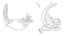
- FIG. 1is an exploded perspective view of one embodiment of an orthopaedic prosthesis
- FIG. 2is a cross-sectional view of one embodiment of a femoral component of the orthopaedic prosthesis of FIG. 1 ;
- FIG. 3is a cross-sectional view of one embodiment of a tibial bearing of the orthopaedic prosthesis of FIG. 1 ;
- FIG. 4is another cross-sectional view of the femoral component of FIG. 2 ;
- FIG. 5is another cross-sectional view of the tibial bearing of FIG. 3 ;
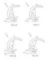
- FIGS. 6-15are side elevational views of the orthopaedic prosthesis of FIG. 1 at various degrees of flexion;
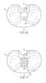
- FIG. 16is a top plan view of another embodiment of the tibial bearing of the orthopaedic prosthesis of FIG. 1 ;
- FIG. 17is a cross-sectional plan view of the tibial bearing of FIG. 16 having a portion of the spine removed;
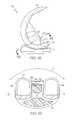
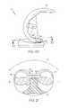
- FIG. 18is a side elevational view of one embodiment of an orthopaedic prosthesis including the tibial bearing of FIG. 16 positioned in an early degree of flexion;
- FIG. 19is a cross-sectional view of the orthopaedic prosthesis of FIG. 18 taken generally along the section line 19 - 19 ;
- FIG. 20is a side elevational view of the orthopaedic prosthesis of FIG. 18 positioned in a late degree of flexion;
- FIG. 21is a cross-sectional view of the orthopaedic prosthesis of FIG. 20 taken generally along the section line 21 - 21 ;
- FIG. 22is an exploded perspective view of another embodiment of an orthopaedic prosthesis.
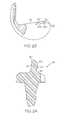
- FIG. 23is a cross-sectional view of one embodiment of a femoral component of the orthopaedic prosthesis of FIG. 22 ;
- FIG. 24is a cross-sectional view of one embodiment of a tibial bearing of the orthopaedic prosthesis of FIG. 22 ;
- FIGS. 25-28are side elevational views of the orthopaedic prosthesis of FIG. 22 at various degrees of flexion.
- Terms representing anatomical referencessuch as anterior, posterior, medial, lateral, superior, inferior, etcetera, may be used throughout this disclosure in reference to both the orthopaedic implants described herein and a patient's natural anatomy. Such terms have well-understood meanings in both the study of anatomy and the field of orthopaedics. Use of such anatomical reference terms in the specification and claims is intended to be consistent with their well-understood meanings unless noted otherwise.
- a posterior stabilized knee orthopaedic prosthesis 10includes a tibial insert or bearing 12 , a femoral component 14 , and a tibial tray 15 .
- the femoral component 14is configured to articulate with the tibial bearing 12 during use.
- the tibial bearing 12is illustratively formed from a polymer material such as a ultra-high molecular weight polyethylene (UHMWPE), but may be formed from other materials, such as a ceramic material, a metallic material, a bio-engineered material, or the like, in other embodiments.
- UHMWPEultra-high molecular weight polyethylene
- the femoral component 14 and the tibial tray 15are illustratively formed from a metallic material such as cobalt-chromium or titanium, but may be formed from other materials, such as a ceramic material, a polymer material, a bio-engineered material, or the like, in other embodiments.
- the femoral component 14is configured to articulate with the tibial bearing 12 , which is configured to be coupled with the tibial tray 15 .
- the illustrative tibial bearing 12is embodied as a rotating or mobile tibial bearing and is configured to rotate relative to the tibial tray 15 during use.
- the tibial bearing 12may be embodied as a fixed tibial bearing, which may be limited or restricted from rotating relative the tibial tray 15 .
- the tibial tray 15is configured to be secured to a surgically-prepared proximal end of a patient's tibia (not shown).
- the tibial tray 15may be secured to the patient's tibia via use of bone adhesive or other attachment means.
- the tibial tray 15includes a platform 80 having an top surface 82 and a bottom surface 84 .
- the top surface 82is generally planar and, in some embodiments, may be highly polished.
- the tibial tray 15also includes a stem 86 extending downwardly from the bottom surface 84 of the platform 80 .
- a cavity or bore 88is defined in the top surface 82 of the platform 80 and extends downwardly into the stem 86 .
- the bore 88is formed to receive a complimentary stem of the tibial bearing 12 as discussed in more detail below.
- the tibial bearing 12is configured to be coupled with the tibial tray 15 .
- the tibial bearing 12includes a platform 16 having an upper bearing surface 18 and a bottom surface 20 .
- the bearing 12includes a stem 22 extending downwardly from the bottom surface 20 of the platform 16 .
- the stem 22is received in the bore 88 of the tibial tray 15 .
- the tibial bearing 12is configured to rotate about an axis defined by the stem 22 relative to the tibial tray 15 .
- the bearing 12may or may not include the stem 22 and/or may include other devices or features to secure the tibial bearing 12 to the tibial tray 15 in a non-rotating configuration.
- the upper bearing surface 18 of the tibial bearing 12includes a medial bearing surface 24 , a lateral bearing surface 26 , and a spine 30 extending upwardly from the platform 16 .
- the medial and lateral bearing surfaces 24 , 26are configured to receive or otherwise contact corresponding medial and lateral condyles 44 , 46 of the femoral component 14 as discussed in more detail below.
- the bearing surfaces 24 , 26may have concave contours in some embodiments.
- the spine 30is positioned between the bearing surfaces 24 , 26 and includes an anterior side 32 and a posterior side 34 .
- the femoral component 14is configured to be coupled to a surgically-prepared surface of the distal end of a patient's femur (not shown).
- the femoral component 14may be secured to the patient's femur via use of bone adhesive or other attachment means.
- the femoral component 14includes an articulating surface 40 having a pair of spaced apart medial and lateral condyles 44 , 46 .
- the condyles 44 , 46replace the natural condyles of the patient's femur and are configured to articulate on the corresponding bearing surfaces 24 , 26 of the platform 16 of the tibial bearing 12 .
- the condyles 44 , 46are spaced apart to define an intracondyle notch or recess 42 therebetween.
- a posterior cam 50 and an anterior cam 52are positioned in the intracondyle notch 42 .
- the posterior cam 50is located toward the posterior side of the femoral component 14 and is configured to engage or otherwise contact the spine 30 of the tibial bearing 12 during flexion as illustrated in and described in more detail below in regard to FIGS. 4-13 .
- each of the posterior cam 50 of the femoral component 14 and the spine 30 of the tibial bearing 12have a substantially “S”-shaped cross-sectional profile in the sagittal plane.
- the posterior cam 50 of the femoral component 14includes a cam surface 54 configured to contact a cam surface 60 of the spine 30 during use.
- the cam surface 54 of the posterior cam 50includes a concave cam surface 56 and a convex cam surface 58 .
- the convex cam surface 58is positioned posteriorly to the concave cam surface 56 .
- the cam surfaces 56 , 58may have similar or different radius of curvatures.
- the convex cam surface 58may have a radius of curvature substantially larger than the radius of curvature of the concave cam surface 56 .
- the convex cam surface 58may have a radius of curvature that is substantially equal to or less than the radius of curvature of the concave cam surface 56 .
- the curvature of the cam surfaces 56 , 58may be defined by a single radius of curvature.
- the particular radius of curvature of the cam surfaces 56 , 58i.e., the “size” of the cam surfaces
- the concave cam surface 56 and the convex cam surface 58 of the femoral component 14may be formed from multiple radii of curvature. For example, in the embodiment illustrated in FIG.
- the concave cam surface 56is defined by a radius of curvature 200 and a radius of curvature 202 , each of which is tangent to the other.
- the radius of curvature 200is about 10.42 millimeters and the radius of curvature 202 is about 8.13 millimeters.
- the convex cam surface 58is defined by a plurality of radii of curvature 204 , 206 , 208 , and 210 . Each of the radii of curvature 204 , 206 , 208 , 210 is tangent with the each adjacent radius of curvature.
- the radius of curvature 204is about 7.14 millimeters
- the radius of curvature 206is about 7.01 millimeters
- the radius of curvature 208is about 7.30 millimeters
- the radius of curvature 210is about 2.30 millimeters.
- a larger or lesser number of radii of curvaturemay be used define the cam surfaces 56 , 58 .
- the radii of curvature 200 , 202 , 204 , 206 , 208 , 210may have other values in other embodiments.
- the cam surface 60 of the tibial bearing 12is defined on the posterior side 34 of the spine 30 .
- the cam surface 60 of the spine 30includes a convex cam surface 62 and a concave cam surface 64 .
- the convex cam surface 62is positioned superiorly relative to the concave cam surface 64 .
- the cam surfaces 62 , 64 of the spine 30may have similar or different radius of curvatures.
- the concave cam surface 64has a radius of curvature substantially larger than the radius of curvature of the convex cam surface 62 .
- the concave cam surface 64may have a radius of curvature that is substantially equal to or less than the radius of curvature of the convex cam surface 62 .
- the curvature of the cam surfaces 62 , 64may be defined by a single radius of curvature.
- the particular radius of curvature of the cam surfaces 62 , 64i.e., the “size” of the cam surfaces
- the convex cam surface 62 and the concave cam surface 64 of the tibial bearing 12may be formed from multiple radii of curvature. For example, in the embodiment illustrated in FIG.
- the concave cam surface 64is defined by a radius of curvature 220 and a radius of curvature 222 , each of which is tangent to the other.
- the radius of curvature 220is about 9.00 millimeters and the radius of curvature 222 is about 13.00 millimeters.
- the convex cam surface 62is defined by a radius of curvature 224 .
- the radius of curvature 224is about 8.00 millimeters.
- a larger or lesser number of radii of curvaturemay be used define the cam surfaces 62 , 64 .
- the radii of curvature 220 , 222 , 224may have other values in other embodiments.
- the femoral component 14 and the tibial bearing 12are configured such that the posterior cam 50 of the femoral component 14 contacts the spine 30 of the tibial bearing 12 during flexion.
- the concave cam surface 56 of the posterior cam 50contacts the convex cam surface 62 of the spine 30 .
- the contact between the posterior cam 50 and the spine 30transitions from contact between the concave cam surface 56 of the posterior cam 50 and the convex cam surface 62 of the spine 30 to contact between the convex cam surface 58 of the posterior cam 50 and the concave surface 64 of the spine 30 during late flexion.
- the posterior cam 50is not in contact with the spine 30 .
- the posterior cam 50 of the femoral component 14contacts the spine 30 of the tibial bearing 12 .
- the concave cam surface 56 of the posterior cam 50initially contacts the convex cam surface 62 of the spine at a predetermined degree of flexion.
- the femoral component 14 and the tibial bearing 12are configured such that the cam surfaces 56 , 62 initially contact each other at about 60 degrees of flexion.
- the degree of flexion at which initial contact between the posterior cam 50 and the spine 30 is establishedmay be determined based on particular criteria such as the size of the orthopaedic prosthesis 10 , the shape or geometry of the articulating surface of the femoral component 14 and/or the tibial bearing 12 , and/or the like.
- the convex cam surface 62 of the spine 30may be fully “seeded” in the concave cam surface 56 of the posterior cam 50 at about 60 degrees of flexion.
- the contact between the posterior cam 50 and the spine 30transitions from the cam surfaces 56 , 62 to the cam surfaces 58 , 64 .
- the contact between the posterior cam 50 and the spine 30begins transitioning to the cam surfaces 58 , 64 at about 80 degrees. At this degree of flexion, initial contact between the convex cam surface 58 of the posterior cam 50 and the concave cam surface 64 of the spine 30 may be established.
- FIGS. 10-15illustrate one embodiment at various degrees of late flexion.
- the orthopaedic prosthesis 10is illustrated at about 100 degrees of flexion in FIG. 10 , at about 110 degrees of flexion in FIG. 11 , at about 120 degrees of flexion in FIG. 12 , at about 130 degrees of flexion in FIG. 13 , at about 140 degrees of flexion in FIG. 14 , and at about 150 degrees of flexion in FIG. 15 .
- contact between the posterior cam 50 and the spine 30is maintained throughout the range of early and late flexion.
- the particular range of early flexion (i.e., the range at which the concave cam surface 56 of the posterior cam 50 contacts the convex cam surface 62 of the spine 30 ) and late flexion (i.e., the range at which the convex cam surface 58 of the posterior cam 50 contacts the concave cam surface 64 of the spine 30 ) of the orthopaedic prosthesis 10may be dependent upon one or more criteria such as the size of the orthopaedic prosthesis 10 , the shape or geometry of the articulating cam surfaces of the tibial bearing 12 and the femoral component 14 , or the like.
- the orthopaedic prosthesis 10is configured to have an early flexion range of about 50 degrees to about 80 degrees and a late flexion range of about 80 degrees to about 150 degrees, but other ranges of flexion may be used in other embodiments.
- the range of early and late flexion of the orthopaedic prosthesis 10is determined, in part, based on the radius of curvature of the cam surface 56 , 58 , 62 , 64 .
- the range of early and late flexion of the orthopaedic prostheses 10may be configured by adjusting the radius of curvature of the cam surfaces 56 , 58 , 62 , 64 .
- the contact surface area between the posterior cam 50 and the spine 30is increased through the flexion range relative to orthopaedic prostheses wherein the posterior cam and/or the spine include planar cam surfaces or cam surfaces having only a concave or convex surface.
- the contact area between the posterior cam 50 and the spine 30is increased in early flexion due to the interface between the concave cam surface 56 of the posterior cam 50 and the convex cam surface 62 of the spine 30 .
- the contact area between the posterior cam 50 and the spine 30is increased in later degrees of flexion due to the interface between the convex cam surface 58 of the posterior cam 50 and the concave cam surface 64 of the spine 30 . Because the contact between the posterior cam 50 and the spine 30 is spread across a greater contact area, the anterior wear of the spine 30 may also be decreased.
- the posterior side 34 of the spine 30may also be curved in the transverse plane. That is, each of the superior, convex cam surface 62 and the inferior, concave cam surface 64 may be convex in the transverse plane direction.
- the convex cam surface 62 of the spine 30may be convexly curved in the transverse plane.
- the concave cam surface 64 of the spine 30may be convexly curved in the transverse plane. The radius of curvature in the transverse plane of the convex cam surface 62 and the concave cam surface 64 may be substantially equal or different.
- the radius of curvature in the transverse plane of the concave cam surface 64may be greater than the radius of curvature in the transverse plane of the convex cam surface 62 .
- the radius of curvature in the transverse plane of the convex cam surface 62may be greater than the radius of curvature in the transverse plane of the concave cam surface 64 .
- the posterior cam 50 of the femoral component 14articulates on the cam surfaces 62 , 64 in the transverse plane such that the femoral component 14 rotates an amount about the spine 30 .
- the concave cam surface 56 of the posterior cam 50when the concave cam surface 56 of the posterior cam 50 is in contact with the convex cam surface 62 of the spine 30 during early flexion, the femoral component 14 may rotate about the spine 30 in a generally medial-lateral direction in the transverse plane as indicated by arrow 70 .
- the concave cam surface 56 of the posterior cam 50may be substantially planar in the medial-lateral direction in some embodiments.
- the concave cam surface 56 of the posterior cam 50 of the femoral component 14may also be curved in the medial-lateral direction.
- the concave cam surface 56may be concavely curved in the medial-lateral direction.
- the radius of curvature in the medial-lateral direction of the concave cam surface 56may be substantially equal to the radius of curvature in the transverse plane of the convex cam surface 62 of the spine 30 .
- the radius of curvature in the medial-lateral direction of the concave cam surface 56may be greater or less than the radius of curvature in the transverse plane of the convex cam surface 62 .
- the amount of rotation between the femoral component 14 and the tibial bearing 12 during early flexionmay be adjusted based on the radius of curvatures in the transverse plane of the cam surfaces 56 , 62 . For example, an increased amount of rotation during early flexion of the orthopaedic prosthesis may be obtained by decreasing the radius of curvature in the transverse plane of the convex cam surface 62 .
- the convex cam surface 58 of the posterior cam 50when the convex cam surface 58 of the posterior cam 50 is in contact with the concave cam surface 64 of the spine 30 during late flexion, the femoral component 14 may rotate about the spine 30 in a generally medially-laterally direction in the transverse plane as indicated by arrow 72 in some embodiments.
- the convex cam surface 58 of the posterior cam 50may be substantially planar in the medial-lateral direction.
- the convex cam surface 58 of the posterior cam 50 of the femoral component 14may be curved in the medial-lateral direction. For example, as illustrated in FIG.
- the convex cam surface 58may be concavely curved in the medial-lateral direction.
- the radius of curvature in the medial-lateral direction of the convex cam surface 58may be substantially equal to the radius of curvature in the medial-lateral direction of the concave cam surface 64 of the spine 30 .
- the radius of curvature in the medial-lateral direction of the convex cam surface 58may be greater or slightly less than the radius of curvature in the medial-lateral direction of the concave cam surface 64 .
- the amount of rotation between the femoral component 14 and the tibial bearing 12 during late flexionmay be adjusted based on the radius of curvatures in the medial-lateral direction of the cam surfaces 58 , 64 .
- the range of late flexion of the illustrative orthopaedic prosthesis 10is greater than the range of early flexion.
- the orthopaedic prosthesis 10may have a range of early flexion that is greater than the range of late flexion. That is, because the range of early and late flexion of the orthopaedic prosthesis is determined, in part, based on the radius of curvature of the cam surface 56 , 58 , 62 , 64 , the range of early and late flexion may be adjusted by changing the radius of curvature of the cam surfaces 56 , 58 , 62 , 64 (i.e., the “size” of the cam surfaces). For example, as illustrated in FIGS.
- the orthopaedic prosthesis 10may include an early flexion range (i.e., the range at which the concave cam surface of the posterior cam 50 contacts the convex cam surface of the spine 30 ) that is greater than the late flexion (i.e., the range at which the convex cam surface of the posterior cam 50 contacts the concave cam surface of the spine 30 ).
- the posterior cam 50 of the femoral component 14includes a cam surface 100 configured to contact a cam surface 102 of the spine 30 during use.
- the cam surface 100 of the posterior cam 50includes a concave cam surface 104 and a convex cam surface 106 .
- the convex cam surface 106is positioned posteriorly to the concave cam surface 104 .
- the concave cam surface 104has a radius of curvature substantially larger than the radius of curvature of the convex cam surface 106 .
- the particular radius of curvature of the cam surfaces 104 , 106may be dependent upon a number of criteria such as the size of the implant, the shape or geometry of the articulating surface of the femoral component 14 and/or the tibial bearing 12 , and/or the like.
- the concave cam surface 104has a radius of curvature of about 12.7 millimeters and the convex cam surface 106 has a radius curvature of about 6.4 millimeters
- the cam surface 102 of the spine 30includes a convex cam surface 108 and a concave cam surface 110 .
- the convex cam surface 108is positioned superiorly relative to the concave cam surface 110 .
- the convex cam surface 108has a radius of curvature substantially larger than the radius of curvature of the concave cam surface 110 .
- the particular radius of curvature of the cam surfaces 108 , 110i.e., the “size” of the cam surfaces
- the convex cam surface 108has a radius of curvature of about 10.3 millimeters and the concave cam surface 110 has a radius curvature of about 1.00 millimeters.
- the range of early flexion of the embodiment of the orthopaedic prosthesis 10 illustrated in FIGS. 22-28is greater than the range of late flexion.
- the posterior cam 50is not in contact with the spine 30 .
- the posterior cam 50 of the femoral component 14contacts the spine 30 of the tibial bearing 12 .
- the concave cam surface 104 of the posterior cam 50contacts the convex cam surface 108 of the spine 30 . Because the radius of curvature of the cam surfaces 104 , 108 are increased, the cams surfaces 104 , 108 maintain contact with each other through a larger range of flexion. As such, the range of early flexion of the orthopaedic prosthesis is increased relative to embodiments wherein the radius of curvature of the cam surfaces 104 , 108 is decreased. After early flexion, the contact between the posterior cam 50 and the spine 30 transitions from the cam surfaces 104 , 108 to the cam surfaces 106 , 110 . For example, in one embodiment as illustrated in FIG.
- the orthopaedic prosthesis 10may be dependent upon one or more criteria such as the size of the orthopaedic prosthesis 10 , the patient's anatomy, or the like.
- the orthopaedic prosthesisis configured to have an early flexion range of about 50 degrees to about 100 degrees and a late flexion range of about 100 degrees to about 150 degrees, but other ranges of flexion may be used in other embodiments.
- the contact surface area between the posterior cam 50 and the spine 30is increased relative to orthopaedic prostheses wherein the posterior cam and/or the spine include planar cam surfaces or cam surfaces having only a concave or convex surface.
- the concave cam surface 104 of the posterior cam 50 and the convex cam surface 108 of the spine 30each have large radius of curvatures, the contact area between the posterior cam 50 an the spine 30 is increased during early flexion.
- the anterior wear of the spine 30may also be decreased.
Landscapes
- Health & Medical Sciences (AREA)
- Orthopedic Medicine & Surgery (AREA)
- Physical Education & Sports Medicine (AREA)
- Cardiology (AREA)
- Oral & Maxillofacial Surgery (AREA)
- Transplantation (AREA)
- Engineering & Computer Science (AREA)
- Biomedical Technology (AREA)
- Heart & Thoracic Surgery (AREA)
- Vascular Medicine (AREA)
- Life Sciences & Earth Sciences (AREA)
- Animal Behavior & Ethology (AREA)
- General Health & Medical Sciences (AREA)
- Public Health (AREA)
- Veterinary Medicine (AREA)
- Prostheses (AREA)
Abstract
Description
Claims (12)
Priority Applications (3)
| Application Number | Priority Date | Filing Date | Title |
|---|---|---|---|
| US13/527,758US8734522B2 (en) | 2008-06-30 | 2012-06-20 | Posterior stabilized orthopaedic prosthesis |
| US13/534,459US9119723B2 (en) | 2008-06-30 | 2012-06-27 | Posterior stabilized orthopaedic prosthesis assembly |
| US14/257,535US9204968B2 (en) | 2008-06-30 | 2014-04-21 | Posterior stabilized orthopaedic prosthesis |
Applications Claiming Priority (2)
| Application Number | Priority Date | Filing Date | Title |
|---|---|---|---|
| US12/165,582US8206451B2 (en) | 2008-06-30 | 2008-06-30 | Posterior stabilized orthopaedic prosthesis |
| US13/527,758US8734522B2 (en) | 2008-06-30 | 2012-06-20 | Posterior stabilized orthopaedic prosthesis |
Related Parent Applications (1)
| Application Number | Title | Priority Date | Filing Date |
|---|---|---|---|
| US12/165,582ContinuationUS8206451B2 (en) | 2008-06-30 | 2008-06-30 | Posterior stabilized orthopaedic prosthesis |
Related Child Applications (2)
| Application Number | Title | Priority Date | Filing Date |
|---|---|---|---|
| US13/534,459Continuation-In-PartUS9119723B2 (en) | 2008-06-30 | 2012-06-27 | Posterior stabilized orthopaedic prosthesis assembly |
| US14/257,535ContinuationUS9204968B2 (en) | 2008-06-30 | 2014-04-21 | Posterior stabilized orthopaedic prosthesis |
Publications (2)
| Publication Number | Publication Date |
|---|---|
| US20120259417A1 US20120259417A1 (en) | 2012-10-11 |
| US8734522B2true US8734522B2 (en) | 2014-05-27 |
Family
ID=41350712
Family Applications (3)
| Application Number | Title | Priority Date | Filing Date |
|---|---|---|---|
| US12/165,582Active2029-07-29US8206451B2 (en) | 2008-06-30 | 2008-06-30 | Posterior stabilized orthopaedic prosthesis |
| US13/527,758ActiveUS8734522B2 (en) | 2008-06-30 | 2012-06-20 | Posterior stabilized orthopaedic prosthesis |
| US14/257,535ActiveUS9204968B2 (en) | 2008-06-30 | 2014-04-21 | Posterior stabilized orthopaedic prosthesis |
Family Applications Before (1)
| Application Number | Title | Priority Date | Filing Date |
|---|---|---|---|
| US12/165,582Active2029-07-29US8206451B2 (en) | 2008-06-30 | 2008-06-30 | Posterior stabilized orthopaedic prosthesis |
Family Applications After (1)
| Application Number | Title | Priority Date | Filing Date |
|---|---|---|---|
| US14/257,535ActiveUS9204968B2 (en) | 2008-06-30 | 2014-04-21 | Posterior stabilized orthopaedic prosthesis |
Country Status (7)
| Country | Link |
|---|---|
| US (3) | US8206451B2 (en) |
| EP (2) | EP2149354B1 (en) |
| JP (1) | JP5535533B2 (en) |
| CN (1) | CN101683289B (en) |
| AU (1) | AU2009202627B2 (en) |
| DK (1) | DK2149354T3 (en) |
| ES (2) | ES2614051T3 (en) |
Cited By (2)
| Publication number | Priority date | Publication date | Assignee | Title |
|---|---|---|---|---|
| US9326864B2 (en) | 2008-06-30 | 2016-05-03 | Depuy (Ireland) | Orthopaedic knee prosthesis having controlled condylar curvature |
| US9452053B2 (en) | 2008-06-30 | 2016-09-27 | Depuy (Ireland) | Orthopaedic knee prosthesis having controlled condylar curvature |
Families Citing this family (110)
| Publication number | Priority date | Publication date | Assignee | Title |
|---|---|---|---|---|
| US7534263B2 (en) | 2001-05-25 | 2009-05-19 | Conformis, Inc. | Surgical tools facilitating increased accuracy, speed and simplicity in performing joint arthroplasty |
| US8480754B2 (en) | 2001-05-25 | 2013-07-09 | Conformis, Inc. | Patient-adapted and improved articular implants, designs and related guide tools |
| US7468075B2 (en) | 2001-05-25 | 2008-12-23 | Conformis, Inc. | Methods and compositions for articular repair |
| US8771365B2 (en) | 2009-02-25 | 2014-07-08 | Conformis, Inc. | Patient-adapted and improved orthopedic implants, designs, and related tools |
| US8882847B2 (en) | 2001-05-25 | 2014-11-11 | Conformis, Inc. | Patient selectable knee joint arthroplasty devices |
| US8617242B2 (en) | 2001-05-25 | 2013-12-31 | Conformis, Inc. | Implant device and method for manufacture |
| US8083745B2 (en) | 2001-05-25 | 2011-12-27 | Conformis, Inc. | Surgical tools for arthroplasty |
| US9603711B2 (en) | 2001-05-25 | 2017-03-28 | Conformis, Inc. | Patient-adapted and improved articular implants, designs and related guide tools |
| US8735773B2 (en) | 2007-02-14 | 2014-05-27 | Conformis, Inc. | Implant device and method for manufacture |
| US8556983B2 (en) | 2001-05-25 | 2013-10-15 | Conformis, Inc. | Patient-adapted and improved orthopedic implants, designs and related tools |
| US20030055502A1 (en) | 2001-05-25 | 2003-03-20 | Philipp Lang | Methods and compositions for articular resurfacing |
| US8545569B2 (en) | 2001-05-25 | 2013-10-01 | Conformis, Inc. | Patient selectable knee arthroplasty devices |
| JP3222440B2 (en) | 1999-08-10 | 2001-10-29 | 住友大阪セメント株式会社 | Plastic injection material |
| US6558426B1 (en) | 2000-11-28 | 2003-05-06 | Medidea, Llc | Multiple-cam, posterior-stabilized knee prosthesis |
| US6719800B2 (en) | 2001-01-29 | 2004-04-13 | Zimmer Technology, Inc. | Constrained prosthetic knee with rotating bearing |
| US6485519B2 (en) | 2001-01-29 | 2002-11-26 | Bristol-Myers Squibb Company | Constrained prosthetic knee with rotating bearing |
| US8439926B2 (en) | 2001-05-25 | 2013-05-14 | Conformis, Inc. | Patient selectable joint arthroplasty devices and surgical tools |
| JP2006501977A (en) | 2002-10-07 | 2006-01-19 | コンフォーミス・インコーポレイテッド | Minimally invasive joint implant with a three-dimensional profile that conforms to the joint surface |
| JP2006505366A (en) | 2002-11-07 | 2006-02-16 | コンフォーミス・インコーポレイテッド | Method of determining meniscus size and shape and devised treatment |
| US9301845B2 (en) | 2005-06-15 | 2016-04-05 | P Tech, Llc | Implant for knee replacement |
| US7955394B2 (en)* | 2005-07-14 | 2011-06-07 | Saga University | Artificial knee joint |
| CA2641966C (en)* | 2005-12-15 | 2016-11-22 | Zimmer, Inc. | Distal femoral knee prostheses |
| US8623026B2 (en) | 2006-02-06 | 2014-01-07 | Conformis, Inc. | Patient selectable joint arthroplasty devices and surgical tools incorporating anatomical relief |
| CN105030296A (en) | 2006-02-06 | 2015-11-11 | 康复米斯公司 | Patient selectable joint arthroplasty devices and surgical tools |
| US8029574B2 (en) | 2006-11-07 | 2011-10-04 | Biomedflex Llc | Prosthetic knee joint |
| US8512413B2 (en) | 2006-11-07 | 2013-08-20 | Biomedflex, Llc | Prosthetic knee joint |
| US8308812B2 (en) | 2006-11-07 | 2012-11-13 | Biomedflex, Llc | Prosthetic joint assembly and joint member therefor |
| WO2008058205A1 (en) | 2006-11-07 | 2008-05-15 | Biomedflex, Llc | Medical implants |
| US20110166671A1 (en) | 2006-11-07 | 2011-07-07 | Kellar Franz W | Prosthetic joint |
| US9005307B2 (en) | 2006-11-07 | 2015-04-14 | Biomedflex, Llc | Prosthetic ball-and-socket joint |
| US8070823B2 (en) | 2006-11-07 | 2011-12-06 | Biomedflex Llc | Prosthetic ball-and-socket joint |
| WO2008157412A2 (en) | 2007-06-13 | 2008-12-24 | Conformis, Inc. | Surgical cutting guide |
| US8632600B2 (en) | 2007-09-25 | 2014-01-21 | Depuy (Ireland) | Prosthesis with modular extensions |
| US8128703B2 (en) | 2007-09-28 | 2012-03-06 | Depuy Products, Inc. | Fixed-bearing knee prosthesis having interchangeable components |
| US9204967B2 (en) | 2007-09-28 | 2015-12-08 | Depuy (Ireland) | Fixed-bearing knee prosthesis having interchangeable components |
| WO2009111626A2 (en) | 2008-03-05 | 2009-09-11 | Conformis, Inc. | Implants for altering wear patterns of articular surfaces |
| WO2009140294A1 (en) | 2008-05-12 | 2009-11-19 | Conformis, Inc. | Devices and methods for treatment of facet and other joints |
| US9168145B2 (en) | 2008-06-30 | 2015-10-27 | Depuy (Ireland) | Posterior stabilized orthopaedic knee prosthesis having controlled condylar curvature |
| US8828086B2 (en) | 2008-06-30 | 2014-09-09 | Depuy (Ireland) | Orthopaedic femoral component having controlled condylar curvature |
| US8236061B2 (en) | 2008-06-30 | 2012-08-07 | Depuy Products, Inc. | Orthopaedic knee prosthesis having controlled condylar curvature |
| US8206451B2 (en) | 2008-06-30 | 2012-06-26 | Depuy Products, Inc. | Posterior stabilized orthopaedic prosthesis |
| US9119723B2 (en) | 2008-06-30 | 2015-09-01 | Depuy (Ireland) | Posterior stabilized orthopaedic prosthesis assembly |
| WO2010099231A2 (en) | 2009-02-24 | 2010-09-02 | Conformis, Inc. | Automated systems for manufacturing patient-specific orthopedic implants and instrumentation |
| US9078755B2 (en)* | 2009-02-25 | 2015-07-14 | Zimmer, Inc. | Ethnic-specific orthopaedic implants and custom cutting jigs |
| SG10201401326SA (en) | 2009-04-16 | 2014-10-30 | Conformis Inc | Patient-specific joint arthroplasty devices for ligament repair |
| US11213397B2 (en) | 2009-05-21 | 2022-01-04 | Depuy Ireland Unlimited Company | Prosthesis with surfaces having different textures and method of making the prosthesis |
| US9101476B2 (en) | 2009-05-21 | 2015-08-11 | Depuy (Ireland) | Prosthesis with surfaces having different textures and method of making the prosthesis |
| US8496666B2 (en) | 2009-08-11 | 2013-07-30 | Imds Corporation | Instrumentation for mobile bearing prosthetics |
| US8998997B2 (en) | 2009-08-11 | 2015-04-07 | Michael D. Ries | Implantable mobile bearing prosthetics |
| US8382848B2 (en)* | 2009-08-11 | 2013-02-26 | Imds Corporation | Position adjustable trial systems for prosthetic implants |
| US9095453B2 (en)* | 2009-08-11 | 2015-08-04 | Michael D. Ries | Position adjustable trial systems for prosthetic implants |
| US8568485B2 (en)* | 2009-08-11 | 2013-10-29 | Imds Corporation | Articulating trials for prosthetic implants |
| EP2316383B1 (en) | 2009-10-30 | 2013-04-17 | DePuy Products, Inc. | Prosthesis with surfaces having different textures |
| EP2319460A1 (en) | 2009-10-30 | 2011-05-11 | DePuy Products, Inc. | Prosthesis with cut-off pegs |
| DK2316384T3 (en) | 2009-10-30 | 2013-07-01 | Depuy Products Inc | Prosthesis with modular extensions |
| EP2316382B1 (en) | 2009-10-30 | 2014-03-05 | DePuy (Ireland) | Prosthesis for cementless fixation |
| EP2319462B1 (en) | 2009-10-30 | 2013-04-03 | DePuy Products, Inc. | Prosthesis with composite component |
| US8900315B2 (en)* | 2009-11-16 | 2014-12-02 | New York Society For The Ruptured And Crippled Maintaining The Hospital For Special Surgery | Constrained condylar knee device |
| US8870964B2 (en)* | 2009-11-16 | 2014-10-28 | New York Society For The Ruptured And Crippled Maintaining The Hospital For Special Surgery | Prosthetic condylar joints with articulating bearing surfaces having a translating contact point during rotation thereof |
| CA2782137A1 (en) | 2009-12-11 | 2011-06-16 | Conformis, Inc. | Patient-specific and patient-engineered orthopedic implants |
| US9011547B2 (en) | 2010-01-21 | 2015-04-21 | Depuy (Ireland) | Knee prosthesis system |
| US20110178606A1 (en) | 2010-01-21 | 2011-07-21 | Depuy Products, Inc. | Tibial components for a knee prosthesis system |
| US8764840B2 (en) | 2010-07-24 | 2014-07-01 | Zimmer, Inc. | Tibial prosthesis |
| ES2632995T3 (en) | 2010-07-24 | 2017-09-18 | Zimmer, Inc. | Asymmetric tibia components for a knee prosthesis |
| CA2993979A1 (en) | 2010-09-10 | 2012-03-15 | Zimmer Gmbh | Femoral prosthesis with medialized patellar groove |
| US8591594B2 (en) | 2010-09-10 | 2013-11-26 | Zimmer, Inc. | Motion facilitating tibial components for a knee prosthesis |
| US8317870B2 (en) | 2010-09-30 | 2012-11-27 | Depuy Products, Inc. | Tibial component of a knee prosthesis having an angled cement pocket |
| US8287601B2 (en)* | 2010-09-30 | 2012-10-16 | Depuy Products, Inc. | Femoral component of a knee prosthesis having an angled cement pocket |
| ES2443827T3 (en)* | 2010-10-05 | 2014-02-20 | Aesculap Ag | Knee Joint Endoprosthesis |
| JP5688281B2 (en)* | 2010-12-10 | 2015-03-25 | 京セラメディカル株式会社 | Artificial knee joint |
| US8603101B2 (en) | 2010-12-17 | 2013-12-10 | Zimmer, Inc. | Provisional tibial prosthesis system |
| CN103327937B (en)* | 2011-01-27 | 2017-08-08 | 史密夫和内修有限公司 | constrained knee prosthesis |
| WO2012112694A2 (en)* | 2011-02-15 | 2012-08-23 | Conformis, Inc. | Medeling, analyzing and using anatomical data for patient-adapted implants. designs, tools and surgical procedures |
| US9308095B2 (en) | 2011-06-16 | 2016-04-12 | Zimmer, Inc. | Femoral component for a knee prosthesis with improved articular characteristics |
| US8551179B2 (en) | 2011-06-16 | 2013-10-08 | Zimmer, Inc. | Femoral prosthesis system having provisional component with visual indicators |
| US9060868B2 (en) | 2011-06-16 | 2015-06-23 | Zimmer, Inc. | Femoral component for a knee prosthesis with bone compacting ridge |
| US8932365B2 (en) | 2011-06-16 | 2015-01-13 | Zimmer, Inc. | Femoral component for a knee prosthesis with improved articular characteristics |
| EP2726021B1 (en)* | 2011-06-30 | 2015-11-04 | DePuy (Ireland) | Posterior stabilized orthopaedic prosthesis assembly |
| JP6472658B2 (en)* | 2011-06-30 | 2019-02-20 | デピュイ・アイルランド・アンリミテッド・カンパニーDepuy Ireland Unlimited Company | Retrostable orthopedic knee prosthesis with controlled condyle curvature |
| EP3308726A3 (en) | 2011-07-13 | 2018-10-24 | The General Hospital Corporation d/b/a Massachusetts General Hospital | Devices for knee joint replacement with anterior cruciate ligament substitution |
| BR112014002240B1 (en)* | 2011-09-19 | 2021-05-11 | Tecres S.P.A | Temporary modular spacer device for human body joints |
| US8409293B1 (en)* | 2011-10-26 | 2013-04-02 | Sevika Holding AG | Knee prosthesis |
| EP3175824B1 (en) | 2011-11-18 | 2019-01-02 | Zimmer, Inc. | Tibial bearing component for a knee prosthesis with improved articular characteristics |
| ES2585838T3 (en) | 2011-11-21 | 2016-10-10 | Zimmer, Inc. | Tibial base plate with asymmetric placement of fixing structures |
| IN2014DN07145A (en) | 2012-01-30 | 2015-04-24 | Zimmer Inc | |
| FR2989568B1 (en)* | 2012-04-19 | 2014-09-05 | Teknimed | IMPLANT SPACER FOR TEMPORARY REPLACEMENT OF KNEE PROSTHESIS |
| US9675471B2 (en) | 2012-06-11 | 2017-06-13 | Conformis, Inc. | Devices, techniques and methods for assessing joint spacing, balancing soft tissues and obtaining desired kinematics for joint implant components |
| IN2014DE00549A (en)* | 2013-03-07 | 2015-06-12 | Depuy Ireland | |
| US9949837B2 (en) | 2013-03-07 | 2018-04-24 | Howmedica Osteonics Corp. | Partially porous bone implant keel |
| US9237953B2 (en) | 2013-03-15 | 2016-01-19 | Depuy (Ireland) | Mechanical assembly of pegs to prosthesis |
| US9925052B2 (en) | 2013-08-30 | 2018-03-27 | Zimmer, Inc. | Method for optimizing implant designs |
| US9144499B2 (en) | 2013-12-17 | 2015-09-29 | Depuy (Ireland) | Low profile mobile/fixed prosthetic knee systems |
| FR3016284B1 (en)* | 2014-01-14 | 2019-08-16 | Evolutis | POSTERO STABILIZED PROSTHESIS OF THE KNEE |
| JP6499674B2 (en)* | 2014-02-10 | 2019-04-10 | リマコーポレート・ソチエタ・ペル・アチオニLimacorporate S.P.A. | Artificial knee joint |
| US10130375B2 (en) | 2014-07-31 | 2018-11-20 | Zimmer, Inc. | Instruments and methods in performing kinematically-aligned total knee arthroplasty |
| KR101696608B1 (en)* | 2014-11-07 | 2017-01-17 | 주식회사 코렌텍 | Artifical Knee Joint preventing Dislocation of Femoral Component |
| CN105030382A (en)* | 2015-02-10 | 2015-11-11 | 江苏奥康尼医疗科技发展有限公司 | Organic polymer material dual-slide artificial knee joint |
| CN104887354B (en)* | 2015-02-10 | 2017-06-30 | 江苏奥康尼医疗科技发展有限公司 | A kind of combined type high-molecular organic material artificial knee joint |
| WO2017053196A1 (en) | 2015-09-21 | 2017-03-30 | Zimmer, Inc. | Prosthesis system including tibial bearing component |
| EP3355834B1 (en) | 2015-09-29 | 2023-01-04 | Zimmer, Inc. | Tibial prosthesis for tibia with varus resection |
| CN105213071A (en)* | 2015-10-21 | 2016-01-06 | 苏州锐进医疗科技有限公司 | A kind of bone conservative knee-joint prosthesis |
| CN106580524B (en)* | 2016-12-12 | 2018-08-07 | 上海昕健医疗技术有限公司 | Posterior stabilized knee prosthesis |
| US10675153B2 (en) | 2017-03-10 | 2020-06-09 | Zimmer, Inc. | Tibial prosthesis with tibial bearing component securing feature |
| WO2018208612A1 (en) | 2017-05-12 | 2018-11-15 | Zimmer, Inc. | Femoral prostheses with upsizing and downsizing capabilities |
| CN107280812A (en)* | 2017-07-18 | 2017-10-24 | 优适医疗科技(苏州)有限公司 | A kind of artificial knee joint prosthesis |
| CN107468381A (en)* | 2017-08-02 | 2017-12-15 | 浙江德康医疗器械有限公司 | A kind of knee joint system |
| US11426282B2 (en) | 2017-11-16 | 2022-08-30 | Zimmer, Inc. | Implants for adding joint inclination to a knee arthroplasty |
| US10835380B2 (en) | 2018-04-30 | 2020-11-17 | Zimmer, Inc. | Posterior stabilized prosthesis system |
| US11382757B1 (en)* | 2020-01-15 | 2022-07-12 | Lento Medical, Inc. | Condylar asymmetry knee prosthesis |
| US11357634B1 (en)* | 2020-01-15 | 2022-06-14 | Lento Medical, Inc. | Posterior-stabilized symmetric knee prosthesis |
Citations (329)
| Publication number | Priority date | Publication date | Assignee | Title |
|---|---|---|---|---|
| GB1065354A (en) | 1964-04-13 | 1967-04-12 | Gen Electric | Improvements in fortification of anodized surfaces |
| US3765033A (en) | 1971-01-19 | 1973-10-16 | D Goldberg | Prosthetic knee joint assembly with mutually slidable and rollable joint sections |
| US3840905A (en)* | 1972-09-18 | 1974-10-15 | Nat Res Dev | Endoprosthetic knee joint |
| US3852045A (en) | 1972-08-14 | 1974-12-03 | Battelle Memorial Institute | Void metal composite material and method |
| US3855638A (en) | 1970-06-04 | 1974-12-24 | Ontario Research Foundation | Surgical prosthetic device with porous metal coating |
| US3869731A (en) | 1973-02-14 | 1975-03-11 | Univ California | Articulated two-part prosthesis replacing the knee joint |
| US4081866A (en) | 1977-02-02 | 1978-04-04 | Howmedica, Inc. | Total anatomical knee prosthesis |
| US4156943A (en) | 1977-08-24 | 1979-06-05 | Collier John P | High-strength porous prosthetic device and process for making the same |
| US4206516A (en) | 1976-12-15 | 1980-06-10 | Ontario Research Foundation | Surgical prosthetic device or implant having pure metal porous coating |
| US4209861A (en) | 1978-02-22 | 1980-07-01 | Howmedica, Inc. | Joint prosthesis |
| US4215439A (en) | 1978-10-16 | 1980-08-05 | Zimmer, USA | Semi-restraining knee prosthesis |
| US4249270A (en)* | 1978-10-06 | 1981-02-10 | Sulzer Brothers Limited | Endoprosthesis for a knee joint |
| US4257129A (en) | 1979-05-21 | 1981-03-24 | Volz Robert G | Prosthetic knee joint tibial implant |
| US4262368A (en) | 1979-09-24 | 1981-04-21 | Wright Manufacturing Company | Rotating and hinged knee prosthesis |
| US4340978A (en) | 1979-07-02 | 1982-07-27 | Biomedical Engineering Corp. | New Jersey meniscal bearing knee replacement |
| US4470158A (en) | 1978-03-10 | 1984-09-11 | Biomedical Engineering Corp. | Joint endoprosthesis |
| US4612160A (en) | 1984-04-02 | 1986-09-16 | Dynamet, Inc. | Porous metal coating process and mold therefor |
| US4673407A (en) | 1985-02-20 | 1987-06-16 | Martin Daniel L | Joint-replacement prosthetic device |
| US4714474A (en) | 1986-05-12 | 1987-12-22 | Dow Corning Wright Corporation | Tibial knee joint prosthesis with removable articulating surface insert |
| US4795468A (en) | 1987-12-23 | 1989-01-03 | Zimmer, Inc. | Mechanism and method for locking a bearing insert to the base of a prosthetic implant |
| US4808185A (en) | 1986-02-07 | 1989-02-28 | Penenberg Brad L | Tibial prosthesis, template and reamer |
| US4822362A (en) | 1987-05-19 | 1989-04-18 | Walker Peter S | Process and apparatus for tibial plateau compenent |
| US4838891A (en) | 1984-11-28 | 1989-06-13 | Branemark Per Ingvar | Joint prothesis |
| US4888021A (en) | 1988-02-02 | 1989-12-19 | Joint Medical Products Corporation | Knee and patellar prosthesis |
| US4938769A (en) | 1989-05-31 | 1990-07-03 | Shaw James A | Modular tibial prosthesis |
| US4944760A (en) | 1983-10-26 | 1990-07-31 | Pfizer Hospital Products Group, Inc. | Method and instrumentation for the replacement of a knee prosthesis |
| US4944757A (en) | 1988-11-07 | 1990-07-31 | Martinez David M | Modulator knee prosthesis system |
| US4950298A (en) | 1988-04-08 | 1990-08-21 | Gustilo Ramon B | Modular knee joint prosthesis |
| US4963152A (en) | 1986-10-27 | 1990-10-16 | Intermedics Orthopedics, Inc. | Asymmetric prosthetic tibial component |
| WO1990014806A1 (en) | 1989-06-02 | 1990-12-13 | Chas F Thackray Limited | Improvements in and relating to knee prostheses |
| US4990163A (en) | 1989-02-06 | 1991-02-05 | Trustees Of The University Of Pennsylvania | Method of depositing calcium phosphate cermamics for bone tissue calcification enhancement |
| US5007933A (en) | 1989-01-31 | 1991-04-16 | Osteonics Corp. | Modular knee prosthesis system |
| US5011496A (en) | 1988-02-02 | 1991-04-30 | Joint Medical Products Corporation | Prosthetic joint |
| FR2653992A1 (en) | 1989-11-09 | 1991-05-10 | Berakassa Richard | Total sliding knee prosthesis |
| US5019103A (en) | 1990-02-05 | 1991-05-28 | Boehringer Mannheim Corporation | Tibial wedge system |
| US5037423A (en) | 1983-10-26 | 1991-08-06 | Pfizer Hospital Products Group, Inc. | Method and instrumentation for the replacement of a knee prosthesis |
| US5071438A (en) | 1990-11-07 | 1991-12-10 | Intermedics Orthopedics, Inc. | Tibial prothesis with pivoting articulating surface |
| US5080675A (en) | 1990-03-12 | 1992-01-14 | Howmedica | Tibial component for a replacement knee prosthesis |
| US5104410A (en) | 1990-10-22 | 1992-04-14 | Intermedics Orthopedics, Inc | Surgical implant having multiple layers of sintered porous coating and method |
| US5108442A (en) | 1991-05-09 | 1992-04-28 | Boehringer Mannheim Corporation | Prosthetic implant locking assembly |
| US5116375A (en) | 1990-08-27 | 1992-05-26 | Hofmann Aaron A | Knee prosthesis |
| US5133758A (en) | 1991-09-16 | 1992-07-28 | Research And Education Institute, Inc. Harbor-Ucla Medical Center | Total knee endoprosthesis with fixed flexion-extension axis of rotation |
| US5147405A (en) | 1990-02-07 | 1992-09-15 | Boehringer Mannheim Corporation | Knee prosthesis |
| US5171283A (en) | 1989-07-11 | 1992-12-15 | Biomedical Engineering Trust | Compound shape rotating bearing |
| US5201766A (en) | 1985-09-11 | 1993-04-13 | Smith & Nephew Richards Inc. | Prosthetic device with porous matrix and method of manufacture |
| US5219362A (en) | 1991-02-07 | 1993-06-15 | Finsbury (Instruments) Limited | Knee prosthesis |
| US5236461A (en) | 1991-03-22 | 1993-08-17 | Forte Mark R | Totally posterior stabilized knee prosthesis |
| US5251468A (en) | 1992-12-14 | 1993-10-12 | Zimmer, Inc. | Method of surface finishing orthopaedic implant devices using a bioactive blasting medium |
| US5258044A (en) | 1992-01-30 | 1993-11-02 | Etex Corporation | Electrophoretic deposition of calcium phosphate material on implants |
| US5271737A (en) | 1992-09-04 | 1993-12-21 | U.S. Medical Products, Inc. | Tibial prosthetic implant with offset stem |
| US5282861A (en) | 1992-03-11 | 1994-02-01 | Ultramet | Open cell tantalum structures for cancellous bone implants and cell and tissue receptors |
| US5308556A (en) | 1993-02-23 | 1994-05-03 | Corning Incorporated | Method of making extrusion dies from powders |
| US5309639A (en) | 1992-11-23 | 1994-05-10 | The Timken Company | Method of making a machine component with lubricated wear surface |
| US5330533A (en) | 1991-02-04 | 1994-07-19 | Walker Peter S | Prosthesis for knee replacement |
| US5330534A (en) | 1992-02-10 | 1994-07-19 | Biomet, Inc. | Knee joint prosthesis with interchangeable components |
| US5344461A (en) | 1993-02-12 | 1994-09-06 | Zimmer, Inc. | Modular implant provisional |
| US5344460A (en) | 1992-10-30 | 1994-09-06 | Encore Orthopedics, Inc. | Prosthesis system |
| US5344494A (en) | 1993-01-21 | 1994-09-06 | Smith & Nephew Richards, Inc. | Method for cleaning porous and roughened surfaces on medical implants |
| DE4308563A1 (en) | 1993-03-18 | 1994-09-22 | Alphanorm Medizintechnik Gmbh | Knee-joint prosthesis |
| US5358527A (en) | 1991-03-22 | 1994-10-25 | Forte Mark R | Total knee prosthesis with resurfacing and posterior stabilization capability |
| US5368881A (en) | 1993-06-10 | 1994-11-29 | Depuy, Inc. | Prosthesis with highly convoluted surface |
| US5370699A (en) | 1993-01-21 | 1994-12-06 | Orthomet, Inc. | Modular knee joint prosthesis |
| US5387240A (en) | 1990-11-14 | 1995-02-07 | Arch Development Corporation | Floating bearing prosthetic knee |
| US5395401A (en) | 1991-06-17 | 1995-03-07 | Bahler; Andre | Prosthetic device for a complex joint |
| US5405396A (en) | 1993-07-01 | 1995-04-11 | Zimmer, Inc. | Tibial prosthesis |
| US5413604A (en) | 1992-12-24 | 1995-05-09 | Osteonics Corp. | Prosthetic knee implant for an anterior cruciate ligament deficient total knee replacement |
| US5414049A (en) | 1993-06-01 | 1995-05-09 | Howmedica Inc. | Non-oxidizing polymeric medical implant |
| US5458637A (en) | 1994-11-21 | 1995-10-17 | Zimmer, Inc. | Orthopaedic base component with modular augmentation block |
| US5480446A (en) | 1990-06-12 | 1996-01-02 | British Technology Group Ltd. | Prosthetic knee joint devices |
| GB2293109A (en) | 1994-09-14 | 1996-03-20 | British Tech Group | Knee Prosthesis Components |
| US5549686A (en) | 1994-06-06 | 1996-08-27 | Zimmer, Inc. | Knee prosthesis having a tapered cam |
| US5571194A (en) | 1994-11-14 | 1996-11-05 | Johnson & Johnson Professional, Inc. | Femoral augmentation system for artificial knee joint |
| US5571187A (en) | 1992-02-27 | 1996-11-05 | Zimmer, Inc. | Implant having a metallic porous surface |
| DE19529824A1 (en) | 1995-08-14 | 1997-02-20 | Bodo Gnutzmann | Bi-condylar endoprosthesis for knee |
| FR2621243B1 (en) | 1987-10-06 | 1997-03-07 | ||
| US5609643A (en) | 1995-03-13 | 1997-03-11 | Johnson & Johnson Professional, Inc. | Knee joint prosthesis |
| US5609639A (en) | 1991-02-04 | 1997-03-11 | Walker; Peter S. | Prosthesis for knee replacement |
| US5639279A (en) | 1995-02-09 | 1997-06-17 | Intermedics Orthopedics, Inc. | Posteriorly-stabilized prosthetic knee |
| US5658342A (en) | 1992-11-16 | 1997-08-19 | Arch Development | Stabilized prosthetic knee |
| US5658344A (en) | 1995-12-29 | 1997-08-19 | Johnson & Johnson Professional, Inc. | Tibial insert reinforcement pin |
| US5681354A (en) | 1996-02-20 | 1997-10-28 | Board Of Regents, University Of Colorado | Asymmetrical femoral component for knee prosthesis |
| US5683468A (en) | 1995-03-13 | 1997-11-04 | Pappas; Michael J. | Mobile bearing total joint replacement |
| US5702463A (en) | 1996-02-20 | 1997-12-30 | Smith & Nephew Inc. | Tibial prosthesis with polymeric liner and liner insertion/removal instrument |
| US5702466A (en) | 1992-04-23 | 1997-12-30 | Biomedical Engineering Trust I | Rotational and translational bearing combination in biological joint replacement |
| US5702458A (en) | 1994-12-09 | 1997-12-30 | New York Society For The Ruptured And Crippled Maintaining The Hospital For Special Surgery | Joint prosthesis |
| US5702464A (en) | 1996-02-20 | 1997-12-30 | Smith & Nephew Inc. | Modular trial tibial insert |
| US5732469A (en) | 1992-04-17 | 1998-03-31 | Kyocera Corporation | Prosthesis and a method of making the same |
| US5755800A (en) | 1996-12-23 | 1998-05-26 | Johnson & Johnson Professional, Inc. | Modular joint prosthesis augmentation system |
| US5755803A (en) | 1994-09-02 | 1998-05-26 | Hudson Surgical Design | Prosthetic implant |
| US5755801A (en) | 1993-07-16 | 1998-05-26 | Walker; Peter Stanley | Prostheses for knee replacement |
| US5765095A (en) | 1996-08-19 | 1998-06-09 | Smith International, Inc. | Polycrystalline diamond bit manufacturing |
| US5766257A (en) | 1997-01-28 | 1998-06-16 | Implant Manufacturing And Testing Corporation | Artificial joint having natural load transfer |
| US5776201A (en) | 1995-10-02 | 1998-07-07 | Johnson & Johnson Professional, Inc. | Modular femoral trial system |
| US5811543A (en) | 1993-10-13 | 1998-09-22 | Ciba Speciality Chemicals Corporation | Fluorescent carbamate-modified phthalocyanine pigments |
| US5824100A (en) | 1996-10-30 | 1998-10-20 | Osteonics Corp. | Knee prosthesis with increased balance and reduced bearing stress |
| US5824103A (en) | 1997-05-12 | 1998-10-20 | Howmedica Inc. | Tibial prosthesis |
| US5824096A (en) | 1994-12-12 | 1998-10-20 | Biomedical Engineering Trust I | Hinged knee prosthesis with condylar bearing |
| US5824102A (en) | 1992-06-19 | 1998-10-20 | Buscayret; Christian | Total knee prosthesis |
| US5871543A (en) | 1996-02-23 | 1999-02-16 | Hofmann; Aaron A. | Tibial prosthesis with mobile bearing member |
| US5871546A (en) | 1995-09-29 | 1999-02-16 | Johnson & Johnson Professional, Inc. | Femoral component condyle design for knee prosthesis |
| US5879394A (en) | 1996-05-28 | 1999-03-09 | Howmedica International Inc. | Tibial element for a replacement knee prosthesis |
| US5879400A (en) | 1996-02-13 | 1999-03-09 | Massachusetts Institute Of Technology | Melt-irradiated ultra high molecular weight polyethylene prosthetic devices |
| US5906644A (en) | 1996-08-30 | 1999-05-25 | Powell; Douglas Hunter | Adjustable modular orthopedic implant |
| US5935173A (en) | 1995-02-03 | 1999-08-10 | Cryptych Pty Ltd | Knee prosthesis |
| US5951603A (en) | 1997-09-25 | 1999-09-14 | Johnson & Johnson Professional, Inc. | Rotatable joint prosthesis with axial securement |
| GB2335145A (en) | 1997-04-16 | 1999-09-15 | Walker Peter S | Total knee replacement capable of anterior-posterior displacement |
| US5957979A (en) | 1997-12-12 | 1999-09-28 | Bristol-Myers Squibb Company | Mobile bearing knee with metal on metal interface |
| US5964808A (en) | 1996-07-11 | 1999-10-12 | Wright Medical Technology, Inc. | Knee prosthesis |
| US5976147A (en) | 1997-07-11 | 1999-11-02 | Johnson & Johnson Professional, Inc | Modular instrumentation for bone preparation and implant trial reduction of orthopedic implants |
| US5984969A (en) | 1995-06-01 | 1999-11-16 | Johnson & Johnson Professional, Inc. | Joint prosthesis augmentation system |
| US5989027A (en) | 1995-12-08 | 1999-11-23 | Sulzer Calcitek Inc. | Dental implant having multiple textured surfaces |
| US6005018A (en) | 1995-06-01 | 1999-12-21 | Johnson & Johnson Professional, Inc. | Augmentation device for joint prosthesis |
| US6004351A (en) | 1996-09-14 | 1999-12-21 | Mizuho Ika Kogyo Kabushiki Kaisha | Prosthetic knee joint |
| WO1999066864A1 (en) | 1998-06-25 | 1999-12-29 | New York Society For The Relief Of The Ruptured And Crippled Maintaining The Hospital For Special Surgery | Retaining mechanism for a modular tibial component of a knee prosthesis |
| US6010534A (en) | 1997-09-25 | 2000-01-04 | Johnson & Johnson Professional, Inc. | Rotatable tibial prosthesis with keyed axial securement |
| FR2780636A1 (en) | 1998-07-06 | 2000-01-07 | Merck Biomaterial France | Modular knee prosthesis comprises lower femoral mounting plate and upper tibial plate for total knee prosthesis |
| US6017975A (en) | 1996-10-02 | 2000-01-25 | Saum; Kenneth Ashley | Process for medical implant of cross-linked ultrahigh molecular weight polyethylene having improved balance of wear properties and oxidation resistance |
| US6039764A (en) | 1997-08-18 | 2000-03-21 | Arch Development Corporation | Prosthetic knee with adjusted center of internal/external rotation |
| US6042780A (en) | 1998-12-15 | 2000-03-28 | Huang; Xiaodi | Method for manufacturing high performance components |
| US6053945A (en) | 1997-09-25 | 2000-04-25 | Johnson & Johnson Professional, Inc. | Joint prosthesis having controlled rotation |
| US6059949A (en) | 1997-04-23 | 2000-05-09 | Cerel (Ceramic Technologies) Ltd. | Method of electrophoretic deposition of ceramic bodies for use in manufacturing dental appliances |
| US6068658A (en) | 1997-03-13 | 2000-05-30 | Zimmer Ltd. | Prosthesis for knee replacement |
| FR2787012A1 (en) | 1998-12-11 | 2000-06-16 | Bex Anne Marie | KNEE ENDOPROSTHESIS |
| US6080195A (en) | 1998-07-08 | 2000-06-27 | Johnson & Johnson Professional, Inc. | Rotatable and translatable joint prosthesis with posterior stabilization |
| US6090144A (en) | 1998-05-12 | 2000-07-18 | Letot; Patrick | Synthetic knee system |
| US6123896A (en) | 1999-01-29 | 2000-09-26 | Ceracon, Inc. | Texture free ballistic grade tantalum product and production method |
| US6123729A (en) | 1998-03-10 | 2000-09-26 | Bristol-Myers Squibb Company | Four compartment knee |
| US6123728A (en) | 1997-09-17 | 2000-09-26 | Smith & Nephew, Inc. | Mobile bearing knee prosthesis |
| US6135857A (en) | 1998-03-02 | 2000-10-24 | General Electric Company | Method for surface enhancement by fluid jet impact |
| US6139581A (en) | 1997-06-06 | 2000-10-31 | Depuy Orthopaedics, Inc. | Posterior compensation tibial tray |
| US6152960A (en) | 1998-10-13 | 2000-11-28 | Biomedical Engineering Trust I | Femoral component for knee endoprosthesis |
| US6162254A (en) | 1997-10-14 | 2000-12-19 | Tornier S.A. | Knee prosthesis |
| US6206926B1 (en) | 1997-10-06 | 2001-03-27 | Biomedical Engineering Trust I | Prosthetic knee joint with enhanced posterior stabilization and dislocation prevention features |
| US6210445B1 (en) | 1999-10-26 | 2001-04-03 | Bristol-Myers Squibb Company | Tibial knee component with a mobile bearing |
| US6210444B1 (en) | 1999-10-26 | 2001-04-03 | Bristol-Myers Squibb Company | Tibial knee component with a mobile bearing |
| US6217618B1 (en) | 1999-10-26 | 2001-04-17 | Bristol-Myers Squibb Company | Tibial knee component with a mobile bearing |
| US6228900B1 (en) | 1996-07-09 | 2001-05-08 | The Orthopaedic Hospital And University Of Southern California | Crosslinking of polyethylene for low wear using radiation and thermal treatments |
| US6238434B1 (en) | 1998-08-05 | 2001-05-29 | Biomedical Engineering Trust I | Knee joint prosthesis with spinout prevention |
| US6245276B1 (en) | 1999-06-08 | 2001-06-12 | Depuy Orthopaedics, Inc. | Method for molding a cross-linked preform |
| US6258127B1 (en) | 1996-09-11 | 2001-07-10 | Plus Endoprothetik Ag | Tibia part of a new joint endoprosthesis |
| US6280476B1 (en) | 1998-10-16 | 2001-08-28 | Biomet Inc. | Hip joint prosthesis convertible in vivo to a modular prosthesis |
| US6281264B1 (en) | 1995-01-20 | 2001-08-28 | The Orthopaedic Hospital | Chemically crosslinked ultrahigh molecular weight polyethylene for artificial human joints |
| US6299646B1 (en) | 1997-09-23 | 2001-10-09 | Tornier Sa | Knee prosthesis with a rotational plate |
| US6319283B1 (en) | 1999-07-02 | 2001-11-20 | Bristol-Myers Squibb Company | Tibial knee component with a mobile bearing |
| FR2809302A1 (en) | 2000-05-23 | 2001-11-30 | Didier Baert | Prosthesis for knee replacement has femoral implant with two thrust bearing pads linked by a cage, having front and rear abutments cooperating with separate profiles of the second prosthesis element |
| US6325828B1 (en) | 1997-12-02 | 2001-12-04 | Rose Biomedical Research | Apparatus for knee prosthesis |
| US6344059B1 (en) | 1996-02-26 | 2002-02-05 | Gabor Krakovits | Knee surface replacement prosthesis |
| US6361564B1 (en) | 1999-02-02 | 2002-03-26 | Aesculap | Total knee joint comprising an insert movable relative to a tenon |
| US6379388B1 (en) | 1999-12-08 | 2002-04-30 | Ortho Development Corporation | Tibial prosthesis locking system and method of repairing knee joint |
| US6428577B1 (en) | 1998-05-20 | 2002-08-06 | Smith & Nephew, Inc. | Mobile bearing knee prosthesis |
| US6443991B1 (en) | 1998-09-21 | 2002-09-03 | Depuy Orthopaedics, Inc. | Posterior stabilized mobile bearing knee |
| US20020138150A1 (en) | 2001-03-26 | 2002-09-26 | Sulzer Orthopedics, Ltd. | Knee prosthesis |
| US6475241B2 (en) | 2000-03-13 | 2002-11-05 | Biomedical Engineering Trust I | Posterior stabilized knee replacement with bearing translation for knees with retained collateral ligaments |
| US6485519B2 (en) | 2001-01-29 | 2002-11-26 | Bristol-Myers Squibb Company | Constrained prosthetic knee with rotating bearing |
| US6491726B2 (en) | 2000-03-08 | 2002-12-10 | Biomedical Engineering Trust I | Posterior stabilized prosthetic knee replacement with bearing translation and dislocation prevention features |
| US6494914B2 (en) | 2000-12-05 | 2002-12-17 | Biomet, Inc. | Unicondylar femoral prosthesis and instruments |
| US6503280B2 (en) | 2000-12-26 | 2003-01-07 | John A. Repicci | Prosthetic knee and method of inserting |
| US20030009232A1 (en) | 1999-03-01 | 2003-01-09 | Robert Metzger | Floating bearing knee joint prosthesis with a fixed tibial post |
| US6506216B1 (en) | 1998-05-13 | 2003-01-14 | Depuy Products, Inc. | Tibial tray with adjustable keel |
| US20030035747A1 (en) | 2001-08-16 | 2003-02-20 | Anderson Gary L. | Method for producing powder metal gears |
| US6524522B2 (en) | 2001-03-07 | 2003-02-25 | Advanced Ceramics Research, Inc. | Method for preparation of metallic foam products and products made |
| US20030044301A1 (en) | 2001-08-16 | 2003-03-06 | Louis-Philippe Lefebvre | Method of making open cell material |
| US6540787B2 (en) | 2000-02-24 | 2003-04-01 | Aesculap | Femoral component of a knee prosthetic including three curvature radii |
| US20030075013A1 (en) | 2001-10-18 | 2003-04-24 | Grohowski Joseph A. | Binder compositions and methods for binder assisted forming |
| US6558426B1 (en) | 2000-11-28 | 2003-05-06 | Medidea, Llc | Multiple-cam, posterior-stabilized knee prosthesis |
| WO2003039609A1 (en) | 2001-11-03 | 2003-05-15 | Accentus Plc | Deposition of coatings on substrates |
| US6569202B2 (en) | 2001-04-02 | 2003-05-27 | Whiteside Biomechanics, Inc. | Tray and liner for joint replacement system |
| US6582469B1 (en) | 1997-12-12 | 2003-06-24 | Tornier S.A. | Knee prosthesis |
| US6582470B1 (en) | 1996-01-22 | 2003-06-24 | Etex Corporation | Surface modification of medical implants |
| US6589283B1 (en) | 2001-05-15 | 2003-07-08 | Biomet, Inc. | Elongated femoral component |
| US6592787B2 (en) | 1997-03-31 | 2003-07-15 | Porvair Corporation | Porous articles and method for the manufacture thereof |
| US20030139817A1 (en) | 2002-01-18 | 2003-07-24 | Finsbury (Development) Limited | Prosthesis |
| FR2835178A1 (en) | 2002-01-31 | 2003-08-01 | Jacques Marie Rousseau | Prosthetic tibial assembly for sliding knee joint has different tibial inserts depending on whether posterior cruciate ligament is retained or not |
| US20030153981A1 (en) | 2002-02-08 | 2003-08-14 | Wang Kathy K. | Porous metallic scaffold for tissue ingrowth |
| US20030171820A1 (en) | 2000-07-12 | 2003-09-11 | Wilshaw Peter Richard | Bone-implant prosthesis |
| US6620198B2 (en) | 1999-10-07 | 2003-09-16 | Exactech, Inc. | Composite bearing inserts for total knee joints |
| US6623526B1 (en) | 1999-01-08 | 2003-09-23 | Corin Limited | Knee prosthesis |
| US6645251B2 (en) | 2001-01-22 | 2003-11-11 | Smith & Nephew, Inc. | Surfaces and processes for wear reducing in orthopaedic implants |
| US20030212161A1 (en) | 2000-04-27 | 2003-11-13 | Mckellop Harry A | Oxidation-resistant and wear-resistant polyethylenes for human joint replacements and methods for making them |
| US20030225456A1 (en) | 2000-05-01 | 2003-12-04 | Ek Steven W. | System and method for joint resurface repair |
| US6660039B1 (en) | 1998-05-20 | 2003-12-09 | Smith & Nephew, Inc. | Mobile bearing knee prosthesis |
| WO2003101647A2 (en) | 2002-06-03 | 2003-12-11 | Forschungszentrum Jülich GmbH | Method for producing highly porous metallic moulded bodies close to the desired final contours |
| US20040015770A1 (en) | 2000-12-27 | 2004-01-22 | Akihiko Kimoto | Path error monitoring method and apparatus thereof |
| US20040039450A1 (en) | 2002-08-26 | 2004-02-26 | Griner Adam M. | Easily assembled provisional orthopaedic implant |
| US6702821B2 (en) | 2000-01-14 | 2004-03-09 | The Bonutti 2003 Trust A | Instrumentation for minimally invasive joint replacement and methods for using same |
| US6719800B2 (en) | 2001-01-29 | 2004-04-13 | Zimmer Technology, Inc. | Constrained prosthetic knee with rotating bearing |
| US6730128B2 (en) | 2001-04-17 | 2004-05-04 | Exactech, Inc. | Prosthetic knee joint |
| EP1421918A1 (en) | 2002-11-19 | 2004-05-26 | Zimmer Technology, Inc. | Prosthetic device and method of making the same |
| JP2004167255A (en) | 2002-11-19 | 2004-06-17 | Zimmer Technology Inc | Femoral component for artificial knee joint |
| WO2004058108A1 (en) | 2002-12-20 | 2004-07-15 | Smith & Nephew, Inc. | High performance knee prostheses |
| US6770078B2 (en) | 2000-01-14 | 2004-08-03 | Peter M. Bonutti | Movable knee implant and methods therefor |
| US6773461B2 (en) | 2001-01-29 | 2004-08-10 | Zimmer Technology, Inc. | Constrained prosthetic knee with rotating bearing |
| WO2004069104A1 (en) | 2003-02-08 | 2004-08-19 | Depuy International Limited | A knee joint prosthesis |
| US20040167633A1 (en) | 2003-02-24 | 2004-08-26 | Depuy Products, Inc. | Metallic implants having roughened surfaces and methods for producing the same |
| US20040186583A1 (en) | 2001-04-25 | 2004-09-23 | Arnold Keller | Knee prosthesis with rotation bearing |
| US6797005B2 (en) | 2001-02-28 | 2004-09-28 | Biomedical Engineering Trust | Deep flexion posterior stabilized knee replacement with bearing translation |
| EP1196118B1 (en) | 1999-07-26 | 2004-10-06 | Michel Bercovy | Novel knee prosthesis |
| EP1470801A1 (en) | 2003-04-24 | 2004-10-27 | Aesculap | Posterior stabilized prosthesis with antitip tibial stud. |
| US20040215345A1 (en) | 2003-02-04 | 2004-10-28 | Zimmer Technology, Inc. | Rotating/non-rotating tibia base plate/insert system |
| US6846329B2 (en) | 2002-02-26 | 2005-01-25 | Mcminn Derek James Wallace | Knee prosthesis |
| US6846327B2 (en) | 2001-05-01 | 2005-01-25 | Amedica Corporation | Radiolucent bone graft |
| US20050021147A1 (en) | 2003-07-24 | 2005-01-27 | Samih Tarabichi | Physiological total knee implant |
| US6849230B1 (en) | 1999-09-14 | 2005-02-01 | Stratec Medical Ag | Mixture of two particulate phases used in the production of a green compact that can be sintered at higher temperatures |
| WO2005009729A2 (en) | 2003-07-24 | 2005-02-03 | Tecomet, Inc. | Assembled non-random foams |
| US6852272B2 (en) | 2001-03-07 | 2005-02-08 | Advanced Ceramics Research, Inc. | Method for preparation of metallic and ceramic foam products and products made |
| US20050055102A1 (en) | 2003-05-12 | 2005-03-10 | Alain Tornier | Set of prosthetic elements for a tibial prosthetic assembly |
| US20050069629A1 (en) | 2001-12-15 | 2005-03-31 | Petra Becker | Method for coating a substrate with calcuim phosphate |
| EP1226799B1 (en) | 2001-01-19 | 2005-05-04 | Mathys AG Bettlach | Inlay for a knee endoprosthesis |
| US20050096747A1 (en) | 2003-10-29 | 2005-05-05 | Tuttle David R. | Tibial knee prosthesis |
| US20050100578A1 (en) | 2003-11-06 | 2005-05-12 | Schmid Steven R. | Bone and tissue scaffolding and method for producing same |
| US6893388B2 (en) | 2001-12-21 | 2005-05-17 | The Procter & Gamble Company | Method of dynamically pre-fastening a disposable absorbent article having a slot-and-tab fastening system |
| US20050123672A1 (en) | 2003-12-03 | 2005-06-09 | Justin Daniel F. | Laser based metal deposition of implant structures |
| US20050143832A1 (en) | 2003-10-17 | 2005-06-30 | Carson Christopher P. | High flexion articular insert |
| US6916340B2 (en) | 1998-10-16 | 2005-07-12 | Biomet, Inc. | Tibial prosthesis convertible in vivo to a modular prosthesis |
| US20050154472A1 (en) | 2002-02-14 | 2005-07-14 | Jacques Afriat | Complete knee prosthesis |
| US6923832B1 (en) | 2002-03-21 | 2005-08-02 | Trigon Incorporated | Revision tibial component |
| US6926738B2 (en) | 2002-06-28 | 2005-08-09 | Depuy Orthopaedics, Inc. | Modular knee joint prosthesis |
| US6942670B2 (en) | 2000-12-27 | 2005-09-13 | Depuy Orthopaedics, Inc. | Prosthesis evaluation assembly and associated method |
| US20050203631A1 (en) | 2004-03-09 | 2005-09-15 | Daniels Michael E. | Tibial implant with a broad keel and a through post |
| WO2005087125A2 (en) | 2004-03-10 | 2005-09-22 | Depuy International Ltd | Orthopaedic operating systems, methods, implants and instruments |
| US20050209702A1 (en) | 2004-03-09 | 2005-09-22 | Todd Dwight T | Tibial knee component with a mobile bearing |
| US20050209701A1 (en) | 2004-03-17 | 2005-09-22 | Toru Suguro And Nakashima Propeller Co., Ltd. | Artificial knee joint |
| US20050278035A1 (en) | 2004-06-11 | 2005-12-15 | Wyss Joseph G | Posterior stabilized mobile bearing knee |
| US20060002810A1 (en) | 2004-07-02 | 2006-01-05 | Grohowski Joseph A Jr | Porous metal articles having a predetermined pore character |
| US6986791B1 (en) | 2003-04-15 | 2006-01-17 | Biomet Manufacturing Corp. | Knee prosthesis with moveable post |
| US20060036329A1 (en) | 2003-02-03 | 2006-02-16 | Webster Vincent A | Mobile bearing unicondylar tibial knee prosthesis |
| US20060052875A1 (en) | 2001-05-01 | 2006-03-09 | Amedica Corporation | Knee prosthesis with ceramic tibial component |
| US7025788B2 (en) | 2001-02-23 | 2006-04-11 | Biomet, Inc. | Knee joint prosthesis |
| US20060100714A1 (en) | 2003-04-02 | 2006-05-11 | Ortho Development Corporation | Tibial augment connector |
| US7048741B2 (en) | 2002-05-10 | 2006-05-23 | Swanson Todd V | Method and apparatus for minimally invasive knee arthroplasty |
| US7066963B2 (en) | 2004-02-26 | 2006-06-27 | Hjs Gelenk-System Gmbh | Tibia plateau for a replacement joint |
| US7070622B1 (en) | 2002-07-03 | 2006-07-04 | Biomet, Inc. | Prosthesis having a modular soft tissue fixation mechanism |
| CN1803106A (en) | 2005-01-11 | 2006-07-19 | 郑诚功 | Improved Artificial Knee Joint |
| US7081137B1 (en) | 2003-06-23 | 2006-07-25 | Howmedica Osteonics Corp. | Knee prosthesis with extended range of motion |
| US20060178749A1 (en) | 2005-02-10 | 2006-08-10 | Zimmer Technology, Inc. | Modular porous implant |
| US20060195195A1 (en) | 2003-07-17 | 2006-08-31 | Albert Burstein | Mobile bearing knee prosthesis |
| US7101401B2 (en) | 2002-01-07 | 2006-09-05 | Plus Orthopedics Ag | Tibial component of a knee-joint endoprosthesis |
| US7105027B2 (en) | 2002-05-08 | 2006-09-12 | Mathys Medical Ltd. | Self-aligning knee prosthesis |
| US7104996B2 (en) | 2000-01-14 | 2006-09-12 | Marctec. Llc | Method of performing surgery |
| US20060228247A1 (en) | 2004-07-02 | 2006-10-12 | Grohowski Joseph A | Controlled porosity article |
| US20060231402A1 (en) | 2003-01-24 | 2006-10-19 | Rolf Clasen | Method for producing metallic moulded bodies comprising a ceramic layer, metallic moulded body, and the use of the same |
| US20060241781A1 (en) | 2005-04-21 | 2006-10-26 | Biomet Manufacturing Corp. | Method and apparatus for use of porous implants |
| US20060257358A1 (en) | 2005-05-13 | 2006-11-16 | Depuy Products, Inc. | Suspension of calcium phosphate particulates for local delivery of therapeutic agents |
| US20060271191A1 (en) | 2005-05-26 | 2006-11-30 | Doxa Ab | Coated implant system with improved adhesion of coating |
| CN1872009A (en) | 2005-05-30 | 2006-12-06 | 贝特曼医疗技术有限公司 | Multifunction bearing joint prosthesis |
| US20060289388A1 (en) | 2005-06-23 | 2006-12-28 | Depuy Products, Inc. | Implants with textured surface and methods for producing the same |
| US7160330B2 (en) | 2003-01-21 | 2007-01-09 | Howmedica Osteonics Corp. | Emulating natural knee kinematics in a knee prosthesis |
| US7175665B2 (en) | 2002-09-09 | 2007-02-13 | Depuy Products, Inc. | Universal tibial augment |
| US20070061014A1 (en) | 2005-09-14 | 2007-03-15 | Hjs Gelenk System Gmbh | Apparatus and method for determining and adjusting the optimal relative position of a functional surface and of correspondingly shaped implant components of an artificial joint |
| US20070073409A1 (en) | 2004-12-01 | 2007-03-29 | Mayo Foundation For Medical Research And Education | Radial-capitellar implant |
| US20070078521A1 (en) | 2005-09-30 | 2007-04-05 | Depuy Products, Inc. | Aluminum oxide coated implants and components |
| EP1779812A1 (en) | 2005-10-26 | 2007-05-02 | Etervind AB | An osseointegration implant |
| US20070100463A1 (en) | 2005-10-31 | 2007-05-03 | Aram Luke J | Modular fixed and mobile bearing prosthesis system |
| US20070129809A1 (en) | 2005-12-05 | 2007-06-07 | Biomet Manufacturing Corp. | Apparatus for use of porous implants |
| US20070135926A1 (en) | 2005-12-14 | 2007-06-14 | Peter Walker | Surface guided knee replacement |
| US20070173948A1 (en) | 2005-04-21 | 2007-07-26 | Biomet Manufacturing Corp. | Porous metal cup with cobalt bearing surface |
| US7255715B2 (en) | 2002-08-30 | 2007-08-14 | Biomet Manufacturing Corp. | Integrated prosthetic assembly |
| US20070196230A1 (en) | 2006-02-17 | 2007-08-23 | Biomet Manufacturing Corp. | Method and apparatus for forming porous metal implants |
| US20070203582A1 (en) | 2006-02-28 | 2007-08-30 | Howmedica Osteonics Corp. | Modular tibial implant |
| US20070219639A1 (en) | 2006-03-14 | 2007-09-20 | Mako Surgical Corporation | Prosthetic device and system and method for implanting prosthetic device |
| WO2007108804A1 (en) | 2006-03-21 | 2007-09-27 | Komistek Richard D | Moment induced total arthroplasty prosthetic |
| US7297164B2 (en) | 2002-11-22 | 2007-11-20 | Zimmer Technology, Inc. | Modular knee prosthesis |
| WO2007119173A3 (en) | 2006-04-13 | 2007-12-21 | Vera Pinskerova | Knee prosthesis |
| US20080004708A1 (en) | 2006-06-30 | 2008-01-03 | Wyss Joseph G | Hinged orthopaedic prosthesis |
| US20080021566A1 (en) | 2006-07-18 | 2008-01-24 | Biomet Manufacturing Corp. | Method and apparatus for a knee implant |
| US7341602B2 (en) | 1999-05-10 | 2008-03-11 | Fell Barry M | Proportioned surgically implantable knee prosthesis |
| US7344460B2 (en) | 2004-12-22 | 2008-03-18 | Rawlings Sporting Goods Company, Inc. | Lacrosse head with cushioned sidewalls |
| US7357817B2 (en) | 2005-05-19 | 2008-04-15 | Howmedica Osteonics Corp. | Modular keel tibial component |
| US20080091272A1 (en) | 2006-10-13 | 2008-04-17 | Aram Luke J | Mobile/fixed prosthetic knee systems |
| US20080114464A1 (en) | 2006-10-13 | 2008-05-15 | Barnett Gary D | Mobile/fixed prosthetic knee systems |
| US20080114462A1 (en) | 2006-11-09 | 2008-05-15 | Hayes Medical, Inc. | System and method for joint arthroplasty |
| EP1923079A1 (en) | 2006-11-16 | 2008-05-21 | Biomet UK Limited | Articular prothesis with a metallic part coated with wear resistant ceramic |
| US20080161927A1 (en) | 2006-10-18 | 2008-07-03 | Warsaw Orthopedic, Inc. | Intervertebral Implant with Porous Portions |
| US20080195108A1 (en) | 2007-02-12 | 2008-08-14 | Jmea Corporation | Total Knee Arthoplasty System |
| US20080199720A1 (en) | 2007-02-21 | 2008-08-21 | Depuy Products, Inc. | Porous metal foam structures and methods |
| US20080206297A1 (en) | 2007-02-28 | 2008-08-28 | Roeder Ryan K | Porous composite biomaterials and related methods |
| US7422605B2 (en) | 2003-07-17 | 2008-09-09 | Exactech, Inc. | Mobile bearing knee prosthesis |
| US20090048680A1 (en) | 2007-08-07 | 2009-02-19 | Aequos Endoprothetik Gmbh | Artificial joint and a joint part intended for this purpose |
| US20090082873A1 (en) | 2007-09-25 | 2009-03-26 | Hazebrouck Stephen A | Fixed-bearing knee prosthesis |
| US7510557B1 (en) | 2000-01-14 | 2009-03-31 | Bonutti Research Inc. | Cutting guide |
| US20090088859A1 (en) | 2007-09-28 | 2009-04-02 | Hazebrouck Stephen A | Fixed-bearing knee prosthesis having interchangeable components |
| US20090084491A1 (en) | 2007-09-25 | 2009-04-02 | Biomet Manufacturing Corp. | Cementless Tibial Tray |
| WO2009046212A2 (en) | 2007-10-05 | 2009-04-09 | Zimmer Spine, Inc. | Medical implant formed from porous metal and method |
| US20090125114A1 (en) | 2007-10-10 | 2009-05-14 | Biomet Manufacturing Corp. | Knee joint prosthesis system and method for implantation |
| US20090192610A1 (en) | 2008-01-30 | 2009-07-30 | Zimmer, Inc. | Orthopedic component of low stiffness |
| US7572292B2 (en) | 2001-12-21 | 2009-08-11 | Smith & Nephew, Inc. | Hinged joint system |
| US7578850B2 (en) | 2005-04-18 | 2009-08-25 | Uni-Knee, Llc | Unicondylar knee implant |
| US20090265012A1 (en) | 2001-06-14 | 2009-10-22 | Alexandria Research Technologies, Inc. | Implants for partial knee arthroplasty |
| US20090265013A1 (en) | 2008-04-17 | 2009-10-22 | Mandell Steven L | Tibial component of an artificial knee joint |
| WO2009128943A2 (en) | 2008-04-17 | 2009-10-22 | Mandell Steven L | Artificial knee joint |
| US7608079B1 (en) | 2004-03-05 | 2009-10-27 | Biomet Manufacturing Corp. | Unicondylar knee apparatus and system |
| US7611519B2 (en) | 2001-11-05 | 2009-11-03 | Depuy (Ireland) Limited | Methods for selecting knee prosthesis elements and device therefor |
| US7618462B2 (en) | 2000-05-01 | 2009-11-17 | Arthrosurface Incorporated | System and method for joint resurface repair |
| US20090292365A1 (en) | 2008-05-22 | 2009-11-26 | Depuy Products, Inc. | Implants With Roughened Surfaces |
| US20090295035A1 (en) | 2003-11-14 | 2009-12-03 | Cherry Creek Orthopedic Specialists | Total knee joint mold and methods |
| US20090319047A1 (en) | 2008-06-24 | 2009-12-24 | Peter Stanley Walker | Recess-ramp knee joint prosthesis |
| US20090326667A1 (en) | 2008-06-30 | 2009-12-31 | Williams John L | Orthopaedic femoral component having controlled condylar curvature |
| US20090326664A1 (en) | 2008-06-30 | 2009-12-31 | Wagner Christel M | Posterior cructiate-retaining orthopaedic knee prosthesis having controlled condylar curvature |
| US20090326666A1 (en) | 2008-06-30 | 2009-12-31 | Wyss Joseph G | Posterior stabilized orthopaedic prosthesis |
| US20090326665A1 (en) | 2008-06-30 | 2009-12-31 | Wyss Joseph G | Posterior stabilized orthopaedic knee prosthesis having controlled condylar curvature |
| US20090326674A1 (en) | 2008-06-30 | 2009-12-31 | Depuy Products, Inc. | Open Celled Metal Implants With Roughened Surfaces and Method for Roughening Open Celled Metal Implants |
| US20090326663A1 (en) | 2008-06-30 | 2009-12-31 | Shouchen Dun | Orthopaedic knee prosthesis having increased axial-rotation |
| US20100016979A1 (en) | 2008-07-16 | 2010-01-21 | Depuy Products, Inc. | Knee prostheses with enhanced kinematics |
| US20100036500A1 (en) | 2008-06-30 | 2010-02-11 | Heldreth Mark A | Orthopaedic knee prosthesis having controlled condylar curvature |
| US20100042225A1 (en) | 2007-08-27 | 2010-02-18 | Vladimir Shur | Knee prosthesis |
| US20100063594A1 (en) | 2007-09-28 | 2010-03-11 | Hazebrouck Stephen A | Fixed-bearing knee prosthesis having interchangeable components |
| US20100076564A1 (en) | 2008-09-23 | 2010-03-25 | Schilling Eric M | Tibial tuberosity advancement implant |
| US20100076563A1 (en) | 2008-09-19 | 2010-03-25 | Smith & Nephew, Inc. | Operatively tuning implants for increased performance |
| US20100094429A1 (en) | 2008-10-02 | 2010-04-15 | Mako Surgical Corp. | Prosthetic device for knee joint and methods of implanting and removing same |
| US20100100189A1 (en) | 2008-10-17 | 2010-04-22 | Biomet Manufacturing Corp. | High flexion tibial tray |
| US20100098574A1 (en) | 2008-08-27 | 2010-04-22 | Liu Hengda D | Mixtures For Forming Porous Constructs |
| US20100100190A1 (en) | 2008-10-17 | 2010-04-22 | Biomet Manufacturing Corp. | Tibial tray having a reinforcing member |
| US20100100191A1 (en) | 2008-10-17 | 2010-04-22 | Biomet Manufacturing Corp. | Tibial Tray Having a Reinforcing Member |
| US7708741B1 (en) | 2001-08-28 | 2010-05-04 | Marctec, Llc | Method of preparing bones for knee replacement surgery |
| US20100125337A1 (en) | 2008-11-18 | 2010-05-20 | Howmedica Osteonics Corp. | Trial implant and method of use |
| US20100161067A1 (en) | 2008-12-23 | 2010-06-24 | Aesculap Ag | Knee prosthesis |
| US7753960B2 (en) | 2004-02-26 | 2010-07-13 | Omni Life Science, Inc. | Modular knee prosthesis |
| US20100191341A1 (en) | 2009-01-28 | 2010-07-29 | Zimmer, Inc. | Lateral condyle posterior inflection for total knee implant |
| US7776044B2 (en) | 2004-12-21 | 2010-08-17 | Zimmer Technology, Inc. | Tibial tray inserter |
| US20100286788A1 (en) | 2009-05-07 | 2010-11-11 | Richard David Komistek | Anterior stabilized knee implant |
| US20100292804A1 (en) | 2007-08-27 | 2010-11-18 | Samuelson Kent M | Systems and methods for providing deeper knee flexion capabilities for knee prosthesis patients |
| US20100305710A1 (en) | 2009-05-28 | 2010-12-02 | Biomet Manufacturing Corp. | Knee Prosthesis |
| US7875081B2 (en) | 2006-09-25 | 2011-01-25 | New York Society For The Ruptured And Crippled Maintaining The Hospital For Special Surgery | Posterior stabilized knee prosthesis |
| US20110029090A1 (en) | 2007-09-25 | 2011-02-03 | Depuy Products, Inc. | Prosthesis with modular extensions |
| US20110029092A1 (en) | 2009-05-21 | 2011-02-03 | Depuy Products, Inc. | Prosthesis with surfaces having different textures and method of making the prosthesis |
| US20110035018A1 (en) | 2007-09-25 | 2011-02-10 | Depuy Products, Inc. | Prosthesis with composite component |
| US20110035017A1 (en) | 2007-09-25 | 2011-02-10 | Depuy Products, Inc. | Prosthesis with cut-off pegs and surgical method |
| US20110106268A1 (en) | 2009-10-30 | 2011-05-05 | Depuy Products, Inc. | Prosthesis for cemented fixation and method for making the prosthesis |
| US20110153026A1 (en) | 2009-12-22 | 2011-06-23 | Zimmer, Gmbh | J-curve for a femoral prosthesis component |
Family Cites Families (12)
| Publication number | Priority date | Publication date | Assignee | Title |
|---|---|---|---|---|
| US3938226A (en)* | 1974-03-13 | 1976-02-17 | Kling-Tecs, Inc. | Apparatus for crimping yarn |
| JPH0553501B2 (en) | 1978-03-10 | 1993-08-10 | Biomedical Eng Corp | |
| EP0495340A1 (en) | 1991-01-18 | 1992-07-22 | Gebrüder Sulzer Aktiengesellschaft | Modular construction kit for the tibial part of a knee joint prosthesis |
| GB9314839D0 (en) | 1993-07-16 | 1993-09-01 | Walker Peter S | Prosthesis for knee replacement |
| GB9310193D0 (en) | 1993-05-18 | 1993-06-30 | Walker Peter S | Knee prosthesis with femoral,tibial conformity |
| SE504971C2 (en) | 1994-07-11 | 1997-06-02 | Sandvik Ab | Saw blade with fluid injection |
| IT1320381B1 (en)* | 2000-05-29 | 2003-11-26 | Olivetti Lexikon Spa | METHOD FOR THE MANUFACTURE OF AN EJECTION HEAD OF DILQUID DROPS, PARTICULARLY SUITABLE FOR OPERATING WITH CHEMICALLY LIQUIDS |
| FR2812540B1 (en) | 2000-08-01 | 2002-10-31 | Jean Manuel Aubaniac | TWO-COMPARTMENTAL KNEE PROSTHESIS |
| AU2005209244A1 (en) | 2004-01-23 | 2005-08-11 | Massachusetts General Hospital | Anterior cruciate ligament substituting knee replacement prosthesis |
| US9168145B2 (en) | 2008-06-30 | 2015-10-27 | Depuy (Ireland) | Posterior stabilized orthopaedic knee prosthesis having controlled condylar curvature |
| US9119723B2 (en) | 2008-06-30 | 2015-09-01 | Depuy (Ireland) | Posterior stabilized orthopaedic prosthesis assembly |
| JP5688281B2 (en)* | 2010-12-10 | 2015-03-25 | 京セラメディカル株式会社 | Artificial knee joint |
- 2008
- 2008-06-30USUS12/165,582patent/US8206451B2/enactiveActive
- 2009
- 2009-06-29JPJP2009153337Apatent/JP5535533B2/enactiveActive
- 2009-06-29AUAU2009202627Apatent/AU2009202627B2/enactiveActive
- 2009-06-30EPEP09164168.8Apatent/EP2149354B1/enactiveActive
- 2009-06-30ESES15150842.1Tpatent/ES2614051T3/enactiveActive
- 2009-06-30CNCN200910166935.6Apatent/CN101683289B/enactiveActive
- 2009-06-30ESES09164168.8Tpatent/ES2534653T3/enactiveActive
- 2009-06-30DKDK09164168Tpatent/DK2149354T3/enactive
- 2009-06-30EPEP15150842.1Apatent/EP2878283B8/enactiveActive
- 2012
- 2012-06-20USUS13/527,758patent/US8734522B2/enactiveActive
- 2014
- 2014-04-21USUS14/257,535patent/US9204968B2/enactiveActive
Patent Citations (407)
| Publication number | Priority date | Publication date | Assignee | Title |
|---|---|---|---|---|
| GB1065354A (en) | 1964-04-13 | 1967-04-12 | Gen Electric | Improvements in fortification of anodized surfaces |
| US3855638A (en) | 1970-06-04 | 1974-12-24 | Ontario Research Foundation | Surgical prosthetic device with porous metal coating |
| US3765033A (en) | 1971-01-19 | 1973-10-16 | D Goldberg | Prosthetic knee joint assembly with mutually slidable and rollable joint sections |
| US3852045A (en) | 1972-08-14 | 1974-12-03 | Battelle Memorial Institute | Void metal composite material and method |
| US3840905A (en)* | 1972-09-18 | 1974-10-15 | Nat Res Dev | Endoprosthetic knee joint |
| US3869731A (en) | 1973-02-14 | 1975-03-11 | Univ California | Articulated two-part prosthesis replacing the knee joint |
| US4206516A (en) | 1976-12-15 | 1980-06-10 | Ontario Research Foundation | Surgical prosthetic device or implant having pure metal porous coating |
| US4081866A (en) | 1977-02-02 | 1978-04-04 | Howmedica, Inc. | Total anatomical knee prosthesis |
| US4156943A (en) | 1977-08-24 | 1979-06-05 | Collier John P | High-strength porous prosthetic device and process for making the same |
| FR2417971B1 (en) | 1978-02-22 | 1985-01-04 | Howmedica | KNEE JOINT PROSTHESIS |
| US4209861A (en) | 1978-02-22 | 1980-07-01 | Howmedica, Inc. | Joint prosthesis |
| US4470158A (en) | 1978-03-10 | 1984-09-11 | Biomedical Engineering Corp. | Joint endoprosthesis |
| US4249270A (en)* | 1978-10-06 | 1981-02-10 | Sulzer Brothers Limited | Endoprosthesis for a knee joint |
| US4215439A (en) | 1978-10-16 | 1980-08-05 | Zimmer, USA | Semi-restraining knee prosthesis |
| US4257129A (en) | 1979-05-21 | 1981-03-24 | Volz Robert G | Prosthetic knee joint tibial implant |
| US4340978A (en) | 1979-07-02 | 1982-07-27 | Biomedical Engineering Corp. | New Jersey meniscal bearing knee replacement |
| US4262368A (en) | 1979-09-24 | 1981-04-21 | Wright Manufacturing Company | Rotating and hinged knee prosthesis |
| US5037423A (en) | 1983-10-26 | 1991-08-06 | Pfizer Hospital Products Group, Inc. | Method and instrumentation for the replacement of a knee prosthesis |
| US4944760A (en) | 1983-10-26 | 1990-07-31 | Pfizer Hospital Products Group, Inc. | Method and instrumentation for the replacement of a knee prosthesis |
| US4612160A (en) | 1984-04-02 | 1986-09-16 | Dynamet, Inc. | Porous metal coating process and mold therefor |
| US4838891A (en) | 1984-11-28 | 1989-06-13 | Branemark Per Ingvar | Joint prothesis |
| US4673407A (en) | 1985-02-20 | 1987-06-16 | Martin Daniel L | Joint-replacement prosthetic device |
| US5201766A (en) | 1985-09-11 | 1993-04-13 | Smith & Nephew Richards Inc. | Prosthetic device with porous matrix and method of manufacture |
| US4808185A (en) | 1986-02-07 | 1989-02-28 | Penenberg Brad L | Tibial prosthesis, template and reamer |
| US4714474A (en) | 1986-05-12 | 1987-12-22 | Dow Corning Wright Corporation | Tibial knee joint prosthesis with removable articulating surface insert |
| US4963152A (en) | 1986-10-27 | 1990-10-16 | Intermedics Orthopedics, Inc. | Asymmetric prosthetic tibial component |
| US4822362A (en) | 1987-05-19 | 1989-04-18 | Walker Peter S | Process and apparatus for tibial plateau compenent |
| FR2621243B1 (en) | 1987-10-06 | 1997-03-07 | ||
| US4795468A (en) | 1987-12-23 | 1989-01-03 | Zimmer, Inc. | Mechanism and method for locking a bearing insert to the base of a prosthetic implant |
| US4888021A (en) | 1988-02-02 | 1989-12-19 | Joint Medical Products Corporation | Knee and patellar prosthesis |
| US5011496A (en) | 1988-02-02 | 1991-04-30 | Joint Medical Products Corporation | Prosthetic joint |
| US4950298A (en) | 1988-04-08 | 1990-08-21 | Gustilo Ramon B | Modular knee joint prosthesis |
| US4944757A (en) | 1988-11-07 | 1990-07-31 | Martinez David M | Modulator knee prosthesis system |
| US5007933A (en) | 1989-01-31 | 1991-04-16 | Osteonics Corp. | Modular knee prosthesis system |
| US4990163A (en) | 1989-02-06 | 1991-02-05 | Trustees Of The University Of Pennsylvania | Method of depositing calcium phosphate cermamics for bone tissue calcification enhancement |
| US4938769A (en) | 1989-05-31 | 1990-07-03 | Shaw James A | Modular tibial prosthesis |
| WO1990014806A1 (en) | 1989-06-02 | 1990-12-13 | Chas F Thackray Limited | Improvements in and relating to knee prostheses |
| US5171283A (en) | 1989-07-11 | 1992-12-15 | Biomedical Engineering Trust | Compound shape rotating bearing |
| FR2653992A1 (en) | 1989-11-09 | 1991-05-10 | Berakassa Richard | Total sliding knee prosthesis |
| US5019103A (en) | 1990-02-05 | 1991-05-28 | Boehringer Mannheim Corporation | Tibial wedge system |
| US5147405A (en) | 1990-02-07 | 1992-09-15 | Boehringer Mannheim Corporation | Knee prosthesis |
| US5080675A (en) | 1990-03-12 | 1992-01-14 | Howmedica | Tibial component for a replacement knee prosthesis |
| US5480446A (en) | 1990-06-12 | 1996-01-02 | British Technology Group Ltd. | Prosthetic knee joint devices |
| US5116375A (en) | 1990-08-27 | 1992-05-26 | Hofmann Aaron A | Knee prosthesis |
| US5104410A (en) | 1990-10-22 | 1992-04-14 | Intermedics Orthopedics, Inc | Surgical implant having multiple layers of sintered porous coating and method |
| US5071438A (en) | 1990-11-07 | 1991-12-10 | Intermedics Orthopedics, Inc. | Tibial prothesis with pivoting articulating surface |
| US5387240A (en) | 1990-11-14 | 1995-02-07 | Arch Development Corporation | Floating bearing prosthetic knee |
| US5609639A (en) | 1991-02-04 | 1997-03-11 | Walker; Peter S. | Prosthesis for knee replacement |
| US5330533A (en) | 1991-02-04 | 1994-07-19 | Walker Peter S | Prosthesis for knee replacement |
| US5219362A (en) | 1991-02-07 | 1993-06-15 | Finsbury (Instruments) Limited | Knee prosthesis |
| US5800552A (en) | 1991-03-22 | 1998-09-01 | Forte; Mark R. | Mechanically linked hinged total knee prosthesis |
| US5236461A (en) | 1991-03-22 | 1993-08-17 | Forte Mark R | Totally posterior stabilized knee prosthesis |
| US5358527A (en) | 1991-03-22 | 1994-10-25 | Forte Mark R | Total knee prosthesis with resurfacing and posterior stabilization capability |
| US5108442A (en) | 1991-05-09 | 1992-04-28 | Boehringer Mannheim Corporation | Prosthetic implant locking assembly |
| US5395401A (en) | 1991-06-17 | 1995-03-07 | Bahler; Andre | Prosthetic device for a complex joint |
| US5326361A (en) | 1991-09-16 | 1994-07-05 | Research And Education Institute, Inc. | Total knee endoprosthesis with fixed flexion-extension axis of rotation |
| US5133758A (en) | 1991-09-16 | 1992-07-28 | Research And Education Institute, Inc. Harbor-Ucla Medical Center | Total knee endoprosthesis with fixed flexion-extension axis of rotation |
| US5258044A (en) | 1992-01-30 | 1993-11-02 | Etex Corporation | Electrophoretic deposition of calcium phosphate material on implants |
| US5997577A (en) | 1992-02-10 | 1999-12-07 | Herrington; Stephen Michael | Knee joint prosthesis |
| US5330534A (en) | 1992-02-10 | 1994-07-19 | Biomet, Inc. | Knee joint prosthesis with interchangeable components |
| US5571187A (en) | 1992-02-27 | 1996-11-05 | Zimmer, Inc. | Implant having a metallic porous surface |
| US5282861A (en) | 1992-03-11 | 1994-02-01 | Ultramet | Open cell tantalum structures for cancellous bone implants and cell and tissue receptors |
| US5732469A (en) | 1992-04-17 | 1998-03-31 | Kyocera Corporation | Prosthesis and a method of making the same |
| US5702466A (en) | 1992-04-23 | 1997-12-30 | Biomedical Engineering Trust I | Rotational and translational bearing combination in biological joint replacement |
| US5824102A (en) | 1992-06-19 | 1998-10-20 | Buscayret; Christian | Total knee prosthesis |
| US5271737A (en) | 1992-09-04 | 1993-12-21 | U.S. Medical Products, Inc. | Tibial prosthetic implant with offset stem |
| US5344460A (en) | 1992-10-30 | 1994-09-06 | Encore Orthopedics, Inc. | Prosthesis system |
| US5658342A (en) | 1992-11-16 | 1997-08-19 | Arch Development | Stabilized prosthetic knee |
| US5309639A (en) | 1992-11-23 | 1994-05-10 | The Timken Company | Method of making a machine component with lubricated wear surface |
| US5251468A (en) | 1992-12-14 | 1993-10-12 | Zimmer, Inc. | Method of surface finishing orthopaedic implant devices using a bioactive blasting medium |
| US5413604A (en) | 1992-12-24 | 1995-05-09 | Osteonics Corp. | Prosthetic knee implant for an anterior cruciate ligament deficient total knee replacement |
| US5344494A (en) | 1993-01-21 | 1994-09-06 | Smith & Nephew Richards, Inc. | Method for cleaning porous and roughened surfaces on medical implants |
| US5370699A (en) | 1993-01-21 | 1994-12-06 | Orthomet, Inc. | Modular knee joint prosthesis |
| US5344461A (en) | 1993-02-12 | 1994-09-06 | Zimmer, Inc. | Modular implant provisional |
| US5308556A (en) | 1993-02-23 | 1994-05-03 | Corning Incorporated | Method of making extrusion dies from powders |
| DE4308563A1 (en) | 1993-03-18 | 1994-09-22 | Alphanorm Medizintechnik Gmbh | Knee-joint prosthesis |
| US5728748A (en) | 1993-06-01 | 1998-03-17 | Howmedica Inc. | Non oxidizing polymeric medical implant |
| US5414049A (en) | 1993-06-01 | 1995-05-09 | Howmedica Inc. | Non-oxidizing polymeric medical implant |
| US20050059750A1 (en) | 1993-06-01 | 2005-03-17 | Howmedica Osteonics Corp. | Non-oxidizing polymeric medical implant |
| US6372814B1 (en) | 1993-06-01 | 2002-04-16 | Stryker Technologies Corporation | Non-oxidizing polymeric medical implant |
| US5449745A (en) | 1993-06-01 | 1995-09-12 | Howmedica Inc. | Non-oxidizing polymeric medical implant |
| US6818020B2 (en) | 1993-06-01 | 2004-11-16 | Howmedica Osteonics Corp. | Non-oxidizing polymeric medical implant |
| US5650485A (en) | 1993-06-01 | 1997-07-22 | Howmedica Inc. | Non-oxidizing polymeric medical implant |
| US5543471A (en) | 1993-06-01 | 1996-08-06 | Howmedica Inc. | Non-oxidizing polymeric medical implant |
| US6174934B1 (en) | 1993-06-01 | 2001-01-16 | Stryker Technologies Corporation | Non-oxidizing polymeric medical implant |
| US6664308B2 (en) | 1993-06-01 | 2003-12-16 | Stryker Technologies Corporation | Non-oxidizing polymeric medical implant |
| US5368881A (en) | 1993-06-10 | 1994-11-29 | Depuy, Inc. | Prosthesis with highly convoluted surface |
| US5658333A (en) | 1993-06-10 | 1997-08-19 | Depuy, Inc. | Prosthesis with highly convoluted surface |
| US5405396A (en) | 1993-07-01 | 1995-04-11 | Zimmer, Inc. | Tibial prosthesis |
| US5755801A (en) | 1993-07-16 | 1998-05-26 | Walker; Peter Stanley | Prostheses for knee replacement |
| US5811543A (en) | 1993-10-13 | 1998-09-22 | Ciba Speciality Chemicals Corporation | Fluorescent carbamate-modified phthalocyanine pigments |
| US5549686A (en) | 1994-06-06 | 1996-08-27 | Zimmer, Inc. | Knee prosthesis having a tapered cam |
| US5755803A (en) | 1994-09-02 | 1998-05-26 | Hudson Surgical Design | Prosthetic implant |
| GB2293109A (en) | 1994-09-14 | 1996-03-20 | British Tech Group | Knee Prosthesis Components |
| US5871545A (en) | 1994-09-14 | 1999-02-16 | Btg International Limited | Prosthetic knee joint device |
| US5571194A (en) | 1994-11-14 | 1996-11-05 | Johnson & Johnson Professional, Inc. | Femoral augmentation system for artificial knee joint |
| US5458637A (en) | 1994-11-21 | 1995-10-17 | Zimmer, Inc. | Orthopaedic base component with modular augmentation block |
| US5702458A (en) | 1994-12-09 | 1997-12-30 | New York Society For The Ruptured And Crippled Maintaining The Hospital For Special Surgery | Joint prosthesis |
| US5824096A (en) | 1994-12-12 | 1998-10-20 | Biomedical Engineering Trust I | Hinged knee prosthesis with condylar bearing |
| US6281264B1 (en) | 1995-01-20 | 2001-08-28 | The Orthopaedic Hospital | Chemically crosslinked ultrahigh molecular weight polyethylene for artificial human joints |
| US5935173A (en) | 1995-02-03 | 1999-08-10 | Cryptych Pty Ltd | Knee prosthesis |
| US5639279A (en) | 1995-02-09 | 1997-06-17 | Intermedics Orthopedics, Inc. | Posteriorly-stabilized prosthetic knee |
| US5609643A (en) | 1995-03-13 | 1997-03-11 | Johnson & Johnson Professional, Inc. | Knee joint prosthesis |
| US5683468A (en) | 1995-03-13 | 1997-11-04 | Pappas; Michael J. | Mobile bearing total joint replacement |
| US5984969A (en) | 1995-06-01 | 1999-11-16 | Johnson & Johnson Professional, Inc. | Joint prosthesis augmentation system |
| US6005018A (en) | 1995-06-01 | 1999-12-21 | Johnson & Johnson Professional, Inc. | Augmentation device for joint prosthesis |
| DE19529824A1 (en) | 1995-08-14 | 1997-02-20 | Bodo Gnutzmann | Bi-condylar endoprosthesis for knee |
| US5871546A (en) | 1995-09-29 | 1999-02-16 | Johnson & Johnson Professional, Inc. | Femoral component condyle design for knee prosthesis |
| US5776201A (en) | 1995-10-02 | 1998-07-07 | Johnson & Johnson Professional, Inc. | Modular femoral trial system |
| US5989027A (en) | 1995-12-08 | 1999-11-23 | Sulzer Calcitek Inc. | Dental implant having multiple textured surfaces |
| US5658344A (en) | 1995-12-29 | 1997-08-19 | Johnson & Johnson Professional, Inc. | Tibial insert reinforcement pin |
| US6582470B1 (en) | 1996-01-22 | 2003-06-24 | Etex Corporation | Surface modification of medical implants |
| US5879400A (en) | 1996-02-13 | 1999-03-09 | Massachusetts Institute Of Technology | Melt-irradiated ultra high molecular weight polyethylene prosthetic devices |
| US5702464A (en) | 1996-02-20 | 1997-12-30 | Smith & Nephew Inc. | Modular trial tibial insert |
| US5702463A (en) | 1996-02-20 | 1997-12-30 | Smith & Nephew Inc. | Tibial prosthesis with polymeric liner and liner insertion/removal instrument |
| US5681354A (en) | 1996-02-20 | 1997-10-28 | Board Of Regents, University Of Colorado | Asymmetrical femoral component for knee prosthesis |
| US5871543A (en) | 1996-02-23 | 1999-02-16 | Hofmann; Aaron A. | Tibial prosthesis with mobile bearing member |
| US6344059B1 (en) | 1996-02-26 | 2002-02-05 | Gabor Krakovits | Knee surface replacement prosthesis |
| US5879394A (en) | 1996-05-28 | 1999-03-09 | Howmedica International Inc. | Tibial element for a replacement knee prosthesis |
| US6228900B1 (en) | 1996-07-09 | 2001-05-08 | The Orthopaedic Hospital And University Of Southern California | Crosslinking of polyethylene for low wear using radiation and thermal treatments |
| US6013103A (en) | 1996-07-11 | 2000-01-11 | Wright Medical Technology, Inc. | Medial pivot knee prosthesis |
| US5964808A (en) | 1996-07-11 | 1999-10-12 | Wright Medical Technology, Inc. | Knee prosthesis |
| US5765095A (en) | 1996-08-19 | 1998-06-09 | Smith International, Inc. | Polycrystalline diamond bit manufacturing |
| US5906644A (en) | 1996-08-30 | 1999-05-25 | Powell; Douglas Hunter | Adjustable modular orthopedic implant |
| US6258127B1 (en) | 1996-09-11 | 2001-07-10 | Plus Endoprothetik Ag | Tibia part of a new joint endoprosthesis |
| US6004351A (en) | 1996-09-14 | 1999-12-21 | Mizuho Ika Kogyo Kabushiki Kaisha | Prosthetic knee joint |
| US6316158B1 (en) | 1996-10-02 | 2001-11-13 | Depuy Orthopaedics, Inc. | Process for medical implant of cross-linked ultrahigh molecular weight polyethylene having improved balance of wear properties and oxidation resistance |
| US6017975A (en) | 1996-10-02 | 2000-01-25 | Saum; Kenneth Ashley | Process for medical implant of cross-linked ultrahigh molecular weight polyethylene having improved balance of wear properties and oxidation resistance |
| US6242507B1 (en) | 1996-10-02 | 2001-06-05 | Depuy Orthopaedics, Inc. | Process for medical implant of cross-linked ultrahigh molecular weight polyethylene having improved balance of wear properties and oxidation resistance |
| US5824100A (en) | 1996-10-30 | 1998-10-20 | Osteonics Corp. | Knee prosthesis with increased balance and reduced bearing stress |
| US5755800A (en) | 1996-12-23 | 1998-05-26 | Johnson & Johnson Professional, Inc. | Modular joint prosthesis augmentation system |
| US5766257A (en) | 1997-01-28 | 1998-06-16 | Implant Manufacturing And Testing Corporation | Artificial joint having natural load transfer |
| US6068658A (en) | 1997-03-13 | 2000-05-30 | Zimmer Ltd. | Prosthesis for knee replacement |
| US6592787B2 (en) | 1997-03-31 | 2003-07-15 | Porvair Corporation | Porous articles and method for the manufacture thereof |
| US6264697B1 (en) | 1997-04-16 | 2001-07-24 | Peter Stanley Walker | Knee prosthesis having guide surfaces for control of anterior-posterior displacement |
| GB2335145A (en) | 1997-04-16 | 1999-09-15 | Walker Peter S | Total knee replacement capable of anterior-posterior displacement |
| US6059949A (en) | 1997-04-23 | 2000-05-09 | Cerel (Ceramic Technologies) Ltd. | Method of electrophoretic deposition of ceramic bodies for use in manufacturing dental appliances |
| US5824103A (en) | 1997-05-12 | 1998-10-20 | Howmedica Inc. | Tibial prosthesis |
| US6139581A (en) | 1997-06-06 | 2000-10-31 | Depuy Orthopaedics, Inc. | Posterior compensation tibial tray |
| US5976147A (en) | 1997-07-11 | 1999-11-02 | Johnson & Johnson Professional, Inc | Modular instrumentation for bone preparation and implant trial reduction of orthopedic implants |
| US6039764A (en) | 1997-08-18 | 2000-03-21 | Arch Development Corporation | Prosthetic knee with adjusted center of internal/external rotation |
| US6123728A (en) | 1997-09-17 | 2000-09-26 | Smith & Nephew, Inc. | Mobile bearing knee prosthesis |
| US20060015185A1 (en) | 1997-09-23 | 2006-01-19 | Pierre Chambat | Knee prosthesis with a rotational plate |
| US6299646B1 (en) | 1997-09-23 | 2001-10-09 | Tornier Sa | Knee prosthesis with a rotational plate |
| US5951603A (en) | 1997-09-25 | 1999-09-14 | Johnson & Johnson Professional, Inc. | Rotatable joint prosthesis with axial securement |
| US6010534A (en) | 1997-09-25 | 2000-01-04 | Johnson & Johnson Professional, Inc. | Rotatable tibial prosthesis with keyed axial securement |
| US6053945A (en) | 1997-09-25 | 2000-04-25 | Johnson & Johnson Professional, Inc. | Joint prosthesis having controlled rotation |
| US6206926B1 (en) | 1997-10-06 | 2001-03-27 | Biomedical Engineering Trust I | Prosthetic knee joint with enhanced posterior stabilization and dislocation prevention features |
| US6162254A (en) | 1997-10-14 | 2000-12-19 | Tornier S.A. | Knee prosthesis |
| US6325828B1 (en) | 1997-12-02 | 2001-12-04 | Rose Biomedical Research | Apparatus for knee prosthesis |
| US6582469B1 (en) | 1997-12-12 | 2003-06-24 | Tornier S.A. | Knee prosthesis |
| US5957979A (en) | 1997-12-12 | 1999-09-28 | Bristol-Myers Squibb Company | Mobile bearing knee with metal on metal interface |
| US6135857A (en) | 1998-03-02 | 2000-10-24 | General Electric Company | Method for surface enhancement by fluid jet impact |
| EP1518521A2 (en) | 1998-03-10 | 2005-03-30 | Bristol-Myers Squibb Company | Four compartment knee |
| US6123729A (en) | 1998-03-10 | 2000-09-26 | Bristol-Myers Squibb Company | Four compartment knee |
| US6090144A (en) | 1998-05-12 | 2000-07-18 | Letot; Patrick | Synthetic knee system |
| US6506215B1 (en) | 1998-05-12 | 2003-01-14 | Patrick Letot | Synthetic knee system |
| US6506216B1 (en) | 1998-05-13 | 2003-01-14 | Depuy Products, Inc. | Tibial tray with adjustable keel |
| US6660039B1 (en) | 1998-05-20 | 2003-12-09 | Smith & Nephew, Inc. | Mobile bearing knee prosthesis |
| US6428577B1 (en) | 1998-05-20 | 2002-08-06 | Smith & Nephew, Inc. | Mobile bearing knee prosthesis |
| US6126692A (en) | 1998-06-25 | 2000-10-03 | New York Society For The Relief Of The Ruptured And Crippled Maintaining The Hospital For Special Surgery | Retaining mechanism for a modular tibial component of a knee prosthesis |
| WO1999066864A1 (en) | 1998-06-25 | 1999-12-29 | New York Society For The Relief Of The Ruptured And Crippled Maintaining The Hospital For Special Surgery | Retaining mechanism for a modular tibial component of a knee prosthesis |
| FR2780636A1 (en) | 1998-07-06 | 2000-01-07 | Merck Biomaterial France | Modular knee prosthesis comprises lower femoral mounting plate and upper tibial plate for total knee prosthesis |
| US6080195A (en) | 1998-07-08 | 2000-06-27 | Johnson & Johnson Professional, Inc. | Rotatable and translatable joint prosthesis with posterior stabilization |
| US6238434B1 (en) | 1998-08-05 | 2001-05-29 | Biomedical Engineering Trust I | Knee joint prosthesis with spinout prevention |
| US6443991B1 (en) | 1998-09-21 | 2002-09-03 | Depuy Orthopaedics, Inc. | Posterior stabilized mobile bearing knee |
| US6152960A (en) | 1998-10-13 | 2000-11-28 | Biomedical Engineering Trust I | Femoral component for knee endoprosthesis |
| US6916340B2 (en) | 1998-10-16 | 2005-07-12 | Biomet, Inc. | Tibial prosthesis convertible in vivo to a modular prosthesis |
| US6280476B1 (en) | 1998-10-16 | 2001-08-28 | Biomet Inc. | Hip joint prosthesis convertible in vivo to a modular prosthesis |
| FR2787012A1 (en) | 1998-12-11 | 2000-06-16 | Bex Anne Marie | KNEE ENDOPROSTHESIS |
| US6042780A (en) | 1998-12-15 | 2000-03-28 | Huang; Xiaodi | Method for manufacturing high performance components |
| US6623526B1 (en) | 1999-01-08 | 2003-09-23 | Corin Limited | Knee prosthesis |
| US6123896A (en) | 1999-01-29 | 2000-09-26 | Ceracon, Inc. | Texture free ballistic grade tantalum product and production method |
| US6361564B1 (en) | 1999-02-02 | 2002-03-26 | Aesculap | Total knee joint comprising an insert movable relative to a tenon |
| US6972039B2 (en) | 1999-03-01 | 2005-12-06 | Biomet, Inc. | Floating bearing knee joint prosthesis with a fixed tibial post |
| US20030009232A1 (en) | 1999-03-01 | 2003-01-09 | Robert Metzger | Floating bearing knee joint prosthesis with a fixed tibial post |
| US7341602B2 (en) | 1999-05-10 | 2008-03-11 | Fell Barry M | Proportioned surgically implantable knee prosthesis |
| US6245276B1 (en) | 1999-06-08 | 2001-06-12 | Depuy Orthopaedics, Inc. | Method for molding a cross-linked preform |
| US6319283B1 (en) | 1999-07-02 | 2001-11-20 | Bristol-Myers Squibb Company | Tibial knee component with a mobile bearing |
| US6893467B1 (en) | 1999-07-26 | 2005-05-17 | Michel Bercovy | Knee prosthesis |
| EP1196118B1 (en) | 1999-07-26 | 2004-10-06 | Michel Bercovy | Novel knee prosthesis |
| US6849230B1 (en) | 1999-09-14 | 2005-02-01 | Stratec Medical Ag | Mixture of two particulate phases used in the production of a green compact that can be sintered at higher temperatures |
| US6620198B2 (en) | 1999-10-07 | 2003-09-16 | Exactech, Inc. | Composite bearing inserts for total knee joints |
| US6210444B1 (en) | 1999-10-26 | 2001-04-03 | Bristol-Myers Squibb Company | Tibial knee component with a mobile bearing |
| US6217618B1 (en) | 1999-10-26 | 2001-04-17 | Bristol-Myers Squibb Company | Tibial knee component with a mobile bearing |
| US6210445B1 (en) | 1999-10-26 | 2001-04-03 | Bristol-Myers Squibb Company | Tibial knee component with a mobile bearing |
| US6379388B1 (en) | 1999-12-08 | 2002-04-30 | Ortho Development Corporation | Tibial prosthesis locking system and method of repairing knee joint |
| US7510557B1 (en) | 2000-01-14 | 2009-03-31 | Bonutti Research Inc. | Cutting guide |
| US6770078B2 (en) | 2000-01-14 | 2004-08-03 | Peter M. Bonutti | Movable knee implant and methods therefor |
| US20100312350A1 (en) | 2000-01-14 | 2010-12-09 | Bonutti Peter M | Segmental knee arthroplasty |
| US7837736B2 (en) | 2000-01-14 | 2010-11-23 | Marctec, Llc | Minimally invasive surgical systems and methods |
| US7615054B1 (en) | 2000-01-14 | 2009-11-10 | Martec, LLC | Bicompartmental knee implant and method |
| US7635390B1 (en) | 2000-01-14 | 2009-12-22 | Marctec, Llc | Joint replacement component having a modular articulating surface |
| US7806896B1 (en) | 2000-01-14 | 2010-10-05 | Marctec, Llc | Knee arthroplasty method |
| US7104996B2 (en) | 2000-01-14 | 2006-09-12 | Marctec. Llc | Method of performing surgery |
| US7708740B1 (en) | 2000-01-14 | 2010-05-04 | Marctec, Llc | Method for total knee arthroplasty and resecting bone in situ |
| US6702821B2 (en) | 2000-01-14 | 2004-03-09 | The Bonutti 2003 Trust A | Instrumentation for minimally invasive joint replacement and methods for using same |
| US7806897B1 (en) | 2000-01-14 | 2010-10-05 | Marctec, Llc | Knee arthroplasty and preservation of the quadriceps mechanism |
| US7749229B1 (en) | 2000-01-14 | 2010-07-06 | Marctec, Llc | Total knee arthroplasty through shortened incision |
| US6540787B2 (en) | 2000-02-24 | 2003-04-01 | Aesculap | Femoral component of a knee prosthetic including three curvature radii |
| EP1129676B1 (en) | 2000-02-24 | 2005-05-11 | Aesculap AG & Co. KG | Femoral piece of a knee prosthesis with three radii of curvature |
| US6491726B2 (en) | 2000-03-08 | 2002-12-10 | Biomedical Engineering Trust I | Posterior stabilized prosthetic knee replacement with bearing translation and dislocation prevention features |
| US6475241B2 (en) | 2000-03-13 | 2002-11-05 | Biomedical Engineering Trust I | Posterior stabilized knee replacement with bearing translation for knees with retained collateral ligaments |
| US6764516B2 (en) | 2000-03-13 | 2004-07-20 | Biomedical Engineering Trust I | Posterior stabilized knee replacement with bearing translation for knees with retained collateral ligaments |
| US20030212161A1 (en) | 2000-04-27 | 2003-11-13 | Mckellop Harry A | Oxidation-resistant and wear-resistant polyethylenes for human joint replacements and methods for making them |
| US20070293647A1 (en) | 2000-04-27 | 2007-12-20 | Orthopaedic Hospital | Oxidation-resistant and wear-resistant polyethylenes for human joint replacements and methods for making them |
| US20030225456A1 (en) | 2000-05-01 | 2003-12-04 | Ek Steven W. | System and method for joint resurface repair |
| US7678151B2 (en) | 2000-05-01 | 2010-03-16 | Ek Steven W | System and method for joint resurface repair |
| US7618462B2 (en) | 2000-05-01 | 2009-11-17 | Arthrosurface Incorporated | System and method for joint resurface repair |
| US20100070045A1 (en) | 2000-05-01 | 2010-03-18 | Arthrosurface Incorparated | System and Method for Joint Resurface Repair |
| FR2809302A1 (en) | 2000-05-23 | 2001-11-30 | Didier Baert | Prosthesis for knee replacement has femoral implant with two thrust bearing pads linked by a cage, having front and rear abutments cooperating with separate profiles of the second prosthesis element |
| US20030171820A1 (en) | 2000-07-12 | 2003-09-11 | Wilshaw Peter Richard | Bone-implant prosthesis |
| US20030199985A1 (en) | 2000-11-28 | 2003-10-23 | Masini Michael A. | Multiple-cam, posterior-stabilized knee prosthesis |
| US6558426B1 (en) | 2000-11-28 | 2003-05-06 | Medidea, Llc | Multiple-cam, posterior-stabilized knee prosthesis |
| US6494914B2 (en) | 2000-12-05 | 2002-12-17 | Biomet, Inc. | Unicondylar femoral prosthesis and instruments |
| US6503280B2 (en) | 2000-12-26 | 2003-01-07 | John A. Repicci | Prosthetic knee and method of inserting |
| US6726724B2 (en) | 2000-12-26 | 2004-04-27 | John A. Repicci | Prosthetic knee |
| US6942670B2 (en) | 2000-12-27 | 2005-09-13 | Depuy Orthopaedics, Inc. | Prosthesis evaluation assembly and associated method |
| US20040015770A1 (en) | 2000-12-27 | 2004-01-22 | Akihiko Kimoto | Path error monitoring method and apparatus thereof |
| EP1226799B1 (en) | 2001-01-19 | 2005-05-04 | Mathys AG Bettlach | Inlay for a knee endoprosthesis |
| US6645251B2 (en) | 2001-01-22 | 2003-11-11 | Smith & Nephew, Inc. | Surfaces and processes for wear reducing in orthopaedic implants |
| US6485519B2 (en) | 2001-01-29 | 2002-11-26 | Bristol-Myers Squibb Company | Constrained prosthetic knee with rotating bearing |
| US6773461B2 (en) | 2001-01-29 | 2004-08-10 | Zimmer Technology, Inc. | Constrained prosthetic knee with rotating bearing |
| US6719800B2 (en) | 2001-01-29 | 2004-04-13 | Zimmer Technology, Inc. | Constrained prosthetic knee with rotating bearing |
| US20080097616A1 (en) | 2001-01-29 | 2008-04-24 | Zimmer Technology, Inc. | Constrained prosthetic knee with rotating bearing |
| US7025788B2 (en) | 2001-02-23 | 2006-04-11 | Biomet, Inc. | Knee joint prosthesis |
| US6797005B2 (en) | 2001-02-28 | 2004-09-28 | Biomedical Engineering Trust | Deep flexion posterior stabilized knee replacement with bearing translation |
| US6852272B2 (en) | 2001-03-07 | 2005-02-08 | Advanced Ceramics Research, Inc. | Method for preparation of metallic and ceramic foam products and products made |
| US6524522B2 (en) | 2001-03-07 | 2003-02-25 | Advanced Ceramics Research, Inc. | Method for preparation of metallic foam products and products made |
| US20020138150A1 (en) | 2001-03-26 | 2002-09-26 | Sulzer Orthopedics, Ltd. | Knee prosthesis |
| JP2002291779A (en) | 2001-03-26 | 2002-10-08 | Sulzer Orthopedics Ltd | Knee prosthetic leg |
| US6569202B2 (en) | 2001-04-02 | 2003-05-27 | Whiteside Biomechanics, Inc. | Tray and liner for joint replacement system |
| US6730128B2 (en) | 2001-04-17 | 2004-05-04 | Exactech, Inc. | Prosthetic knee joint |
| US20040186583A1 (en) | 2001-04-25 | 2004-09-23 | Arnold Keller | Knee prosthesis with rotation bearing |
| US6846327B2 (en) | 2001-05-01 | 2005-01-25 | Amedica Corporation | Radiolucent bone graft |
| US20060052875A1 (en) | 2001-05-01 | 2006-03-09 | Amedica Corporation | Knee prosthesis with ceramic tibial component |
| US6589283B1 (en) | 2001-05-15 | 2003-07-08 | Biomet, Inc. | Elongated femoral component |
| US20090265012A1 (en) | 2001-06-14 | 2009-10-22 | Alexandria Research Technologies, Inc. | Implants for partial knee arthroplasty |
| US20030035747A1 (en) | 2001-08-16 | 2003-02-20 | Anderson Gary L. | Method for producing powder metal gears |
| US20030044301A1 (en) | 2001-08-16 | 2003-03-06 | Louis-Philippe Lefebvre | Method of making open cell material |
| US6660224B2 (en) | 2001-08-16 | 2003-12-09 | National Research Council Of Canada | Method of making open cell material |
| US7708741B1 (en) | 2001-08-28 | 2010-05-04 | Marctec, Llc | Method of preparing bones for knee replacement surgery |
| US20030075013A1 (en) | 2001-10-18 | 2003-04-24 | Grohowski Joseph A. | Binder compositions and methods for binder assisted forming |
| WO2003039609A1 (en) | 2001-11-03 | 2003-05-15 | Accentus Plc | Deposition of coatings on substrates |
| US7611519B2 (en) | 2001-11-05 | 2009-11-03 | Depuy (Ireland) Limited | Methods for selecting knee prosthesis elements and device therefor |
| US20050069629A1 (en) | 2001-12-15 | 2005-03-31 | Petra Becker | Method for coating a substrate with calcuim phosphate |
| US7572292B2 (en) | 2001-12-21 | 2009-08-11 | Smith & Nephew, Inc. | Hinged joint system |
| US6893388B2 (en) | 2001-12-21 | 2005-05-17 | The Procter & Gamble Company | Method of dynamically pre-fastening a disposable absorbent article having a slot-and-tab fastening system |
| US7101401B2 (en) | 2002-01-07 | 2006-09-05 | Plus Orthopedics Ag | Tibial component of a knee-joint endoprosthesis |
| US6869448B2 (en) | 2002-01-18 | 2005-03-22 | Finsbury (Development) Limited | Prosthesis |
| US20030139817A1 (en) | 2002-01-18 | 2003-07-24 | Finsbury (Development) Limited | Prosthesis |
| FR2835178A1 (en) | 2002-01-31 | 2003-08-01 | Jacques Marie Rousseau | Prosthetic tibial assembly for sliding knee joint has different tibial inserts depending on whether posterior cruciate ligament is retained or not |
| US20030153981A1 (en) | 2002-02-08 | 2003-08-14 | Wang Kathy K. | Porous metallic scaffold for tissue ingrowth |
| US20050154472A1 (en) | 2002-02-14 | 2005-07-14 | Jacques Afriat | Complete knee prosthesis |
| US6846329B2 (en) | 2002-02-26 | 2005-01-25 | Mcminn Derek James Wallace | Knee prosthesis |
| US6923832B1 (en) | 2002-03-21 | 2005-08-02 | Trigon Incorporated | Revision tibial component |
| US7105027B2 (en) | 2002-05-08 | 2006-09-12 | Mathys Medical Ltd. | Self-aligning knee prosthesis |
| US7048741B2 (en) | 2002-05-10 | 2006-05-23 | Swanson Todd V | Method and apparatus for minimally invasive knee arthroplasty |
| US20050249625A1 (en) | 2002-06-03 | 2005-11-10 | Martin Bram | Method for producing highly porous metallic moulded bodies close to the desired final contours |
| WO2003101647A2 (en) | 2002-06-03 | 2003-12-11 | Forschungszentrum Jülich GmbH | Method for producing highly porous metallic moulded bodies close to the desired final contours |
| US7147819B2 (en) | 2002-06-03 | 2006-12-12 | Forschungszentrum Julich Gmbh | Method for producing highly porous metallic moulded bodies close to the desired final contours |
| US6926738B2 (en) | 2002-06-28 | 2005-08-09 | Depuy Orthopaedics, Inc. | Modular knee joint prosthesis |
| EP1374805B1 (en) | 2002-06-28 | 2012-08-22 | Depuy Orthopaedics, Inc. | Modular knee joint prosthesis |
| US7070622B1 (en) | 2002-07-03 | 2006-07-04 | Biomet, Inc. | Prosthesis having a modular soft tissue fixation mechanism |
| US20040039450A1 (en) | 2002-08-26 | 2004-02-26 | Griner Adam M. | Easily assembled provisional orthopaedic implant |
| US7255715B2 (en) | 2002-08-30 | 2007-08-14 | Biomet Manufacturing Corp. | Integrated prosthetic assembly |
| US7175665B2 (en) | 2002-09-09 | 2007-02-13 | Depuy Products, Inc. | Universal tibial augment |
| US6770099B2 (en) | 2002-11-19 | 2004-08-03 | Zimmer Technology, Inc. | Femoral prosthesis |
| JP2004167255A (en) | 2002-11-19 | 2004-06-17 | Zimmer Technology Inc | Femoral component for artificial knee joint |
| EP1421918A1 (en) | 2002-11-19 | 2004-05-26 | Zimmer Technology, Inc. | Prosthetic device and method of making the same |
| US7527650B2 (en) | 2002-11-22 | 2009-05-05 | Zimmer Technology, Inc. | Modular knee prosthesis |
| US7297164B2 (en) | 2002-11-22 | 2007-11-20 | Zimmer Technology, Inc. | Modular knee prosthesis |
| US20100042224A1 (en) | 2002-12-20 | 2010-02-18 | Smith & Nephew, Inc. | High performance knee prostheses |
| US7326252B2 (en) | 2002-12-20 | 2008-02-05 | Smith & Nephew, Inc. | High performance knee prostheses |
| US20040243244A1 (en) | 2002-12-20 | 2004-12-02 | Jason Otto | High performance knee prostheses |
| WO2004058108A1 (en) | 2002-12-20 | 2004-07-15 | Smith & Nephew, Inc. | High performance knee prostheses |
| US20110125280A1 (en) | 2002-12-20 | 2011-05-26 | Otto Jason K | High Performance Knee Prostheses |
| US20080119940A1 (en) | 2002-12-20 | 2008-05-22 | Otto Jason K | High performance knee prostheses |
| US7922771B2 (en) | 2002-12-20 | 2011-04-12 | Smith & Nephew, Inc. | High performance knee prostheses |
| EP1440675B1 (en) | 2003-01-21 | 2010-08-11 | Howmedica Osteonics Corp. | Emulating natural knee kinematics in a knee prothesis |
| US7160330B2 (en) | 2003-01-21 | 2007-01-09 | Howmedica Osteonics Corp. | Emulating natural knee kinematics in a knee prosthesis |
| US20060231402A1 (en) | 2003-01-24 | 2006-10-19 | Rolf Clasen | Method for producing metallic moulded bodies comprising a ceramic layer, metallic moulded body, and the use of the same |
| US20060036329A1 (en) | 2003-02-03 | 2006-02-16 | Webster Vincent A | Mobile bearing unicondylar tibial knee prosthesis |
| US20040215345A1 (en) | 2003-02-04 | 2004-10-28 | Zimmer Technology, Inc. | Rotating/non-rotating tibia base plate/insert system |
| US20090306785A1 (en) | 2003-02-08 | 2009-12-10 | Richard Farrar | Knee joint prosthesis |
| WO2004069104A1 (en) | 2003-02-08 | 2004-08-19 | Depuy International Limited | A knee joint prosthesis |
| US20040167633A1 (en) | 2003-02-24 | 2004-08-26 | Depuy Products, Inc. | Metallic implants having roughened surfaces and methods for producing the same |
| US20060100714A1 (en) | 2003-04-02 | 2006-05-11 | Ortho Development Corporation | Tibial augment connector |
| US6986791B1 (en) | 2003-04-15 | 2006-01-17 | Biomet Manufacturing Corp. | Knee prosthesis with moveable post |
| US20040243245A1 (en) | 2003-04-24 | 2004-12-02 | Sylvie Plumet | Postero-stabilised prosthesis with non-shifting tibial stud |
| EP1470801A1 (en) | 2003-04-24 | 2004-10-27 | Aesculap | Posterior stabilized prosthesis with antitip tibial stud. |
| US20050055102A1 (en) | 2003-05-12 | 2005-03-10 | Alain Tornier | Set of prosthetic elements for a tibial prosthetic assembly |
| US7081137B1 (en) | 2003-06-23 | 2006-07-25 | Howmedica Osteonics Corp. | Knee prosthesis with extended range of motion |
| US7422605B2 (en) | 2003-07-17 | 2008-09-09 | Exactech, Inc. | Mobile bearing knee prosthesis |
| US20060195195A1 (en) | 2003-07-17 | 2006-08-31 | Albert Burstein | Mobile bearing knee prosthesis |
| US20050021147A1 (en) | 2003-07-24 | 2005-01-27 | Samih Tarabichi | Physiological total knee implant |
| WO2005009489A2 (en) | 2003-07-24 | 2005-02-03 | Tecomet, Inc. | Assembled non-random foams |
| WO2005009729A2 (en) | 2003-07-24 | 2005-02-03 | Tecomet, Inc. | Assembled non-random foams |
| US7094259B2 (en) | 2003-07-24 | 2006-08-22 | Samih Tarabichi | Physiological total knee implant |
| US20050143832A1 (en) | 2003-10-17 | 2005-06-30 | Carson Christopher P. | High flexion articular insert |
| US20050096747A1 (en) | 2003-10-29 | 2005-05-05 | Tuttle David R. | Tibial knee prosthesis |
| US7261740B2 (en) | 2003-10-29 | 2007-08-28 | Wright Medical Technology, Inc. | Tibial knee prosthesis |
| US20050100578A1 (en) | 2003-11-06 | 2005-05-12 | Schmid Steven R. | Bone and tissue scaffolding and method for producing same |
| US20090295035A1 (en) | 2003-11-14 | 2009-12-03 | Cherry Creek Orthopedic Specialists | Total knee joint mold and methods |
| US20050123672A1 (en) | 2003-12-03 | 2005-06-09 | Justin Daniel F. | Laser based metal deposition of implant structures |
| US7753960B2 (en) | 2004-02-26 | 2010-07-13 | Omni Life Science, Inc. | Modular knee prosthesis |
| US7066963B2 (en) | 2004-02-26 | 2006-06-27 | Hjs Gelenk-System Gmbh | Tibia plateau for a replacement joint |
| US7608079B1 (en) | 2004-03-05 | 2009-10-27 | Biomet Manufacturing Corp. | Unicondylar knee apparatus and system |
| US20050209702A1 (en) | 2004-03-09 | 2005-09-22 | Todd Dwight T | Tibial knee component with a mobile bearing |
| US20050203631A1 (en) | 2004-03-09 | 2005-09-15 | Daniels Michael E. | Tibial implant with a broad keel and a through post |
| US20080269596A1 (en) | 2004-03-10 | 2008-10-30 | Ian Revie | Orthpaedic Monitoring Systems, Methods, Implants and Instruments |
| WO2005087125A2 (en) | 2004-03-10 | 2005-09-22 | Depuy International Ltd | Orthopaedic operating systems, methods, implants and instruments |
| EP1591082A2 (en) | 2004-03-17 | 2005-11-02 | Nakashima Propeller Co., Ltd. | An artificial knee joint |
| US7678152B2 (en) | 2004-03-17 | 2010-03-16 | Toru Suguro | Artificial knee joint |
| US20050209701A1 (en) | 2004-03-17 | 2005-09-22 | Toru Suguro And Nakashima Propeller Co., Ltd. | Artificial knee joint |
| US20050278035A1 (en) | 2004-06-11 | 2005-12-15 | Wyss Joseph G | Posterior stabilized mobile bearing knee |
| JP2006015133A (en) | 2004-06-11 | 2006-01-19 | Depuy Products Inc | Knee prosthesis with movable bearings stabilized at the rear |
| US20060002810A1 (en) | 2004-07-02 | 2006-01-05 | Grohowski Joseph A Jr | Porous metal articles having a predetermined pore character |
| US20060228247A1 (en) | 2004-07-02 | 2006-10-12 | Grohowski Joseph A | Controlled porosity article |
| WO2006014294A1 (en) | 2004-07-02 | 2006-02-09 | Grohowski Joseph A | Porous metal articles formed using an extractable particulate |
| US20070073409A1 (en) | 2004-12-01 | 2007-03-29 | Mayo Foundation For Medical Research And Education | Radial-capitellar implant |
| US7776044B2 (en) | 2004-12-21 | 2010-08-17 | Zimmer Technology, Inc. | Tibial tray inserter |
| US7344460B2 (en) | 2004-12-22 | 2008-03-18 | Rawlings Sporting Goods Company, Inc. | Lacrosse head with cushioned sidewalls |
| CN1803106A (en) | 2005-01-11 | 2006-07-19 | 郑诚功 | Improved Artificial Knee Joint |
| US20060178749A1 (en) | 2005-02-10 | 2006-08-10 | Zimmer Technology, Inc. | Modular porous implant |
| US7578850B2 (en) | 2005-04-18 | 2009-08-25 | Uni-Knee, Llc | Unicondylar knee implant |
| US20060241781A1 (en) | 2005-04-21 | 2006-10-26 | Biomet Manufacturing Corp. | Method and apparatus for use of porous implants |
| US20070173948A1 (en) | 2005-04-21 | 2007-07-26 | Biomet Manufacturing Corp. | Porous metal cup with cobalt bearing surface |
| US20060257358A1 (en) | 2005-05-13 | 2006-11-16 | Depuy Products, Inc. | Suspension of calcium phosphate particulates for local delivery of therapeutic agents |
| US7357817B2 (en) | 2005-05-19 | 2008-04-15 | Howmedica Osteonics Corp. | Modular keel tibial component |
| US20060271191A1 (en) | 2005-05-26 | 2006-11-30 | Doxa Ab | Coated implant system with improved adhesion of coating |
| WO2006130350A2 (en) | 2005-05-27 | 2006-12-07 | Amedica Corporation | Knee prosthesis with ceramic tibial component |
| CN1872009A (en) | 2005-05-30 | 2006-12-06 | 贝特曼医疗技术有限公司 | Multifunction bearing joint prosthesis |
| US20060289388A1 (en) | 2005-06-23 | 2006-12-28 | Depuy Products, Inc. | Implants with textured surface and methods for producing the same |
| US20070061014A1 (en) | 2005-09-14 | 2007-03-15 | Hjs Gelenk System Gmbh | Apparatus and method for determining and adjusting the optimal relative position of a functional surface and of correspondingly shaped implant components of an artificial joint |
| US20070078521A1 (en) | 2005-09-30 | 2007-04-05 | Depuy Products, Inc. | Aluminum oxide coated implants and components |
| EP1779812A1 (en) | 2005-10-26 | 2007-05-02 | Etervind AB | An osseointegration implant |
| US20070100463A1 (en) | 2005-10-31 | 2007-05-03 | Aram Luke J | Modular fixed and mobile bearing prosthesis system |
| US20070129809A1 (en) | 2005-12-05 | 2007-06-07 | Biomet Manufacturing Corp. | Apparatus for use of porous implants |
| US20070135926A1 (en) | 2005-12-14 | 2007-06-14 | Peter Walker | Surface guided knee replacement |
| US20070196230A1 (en) | 2006-02-17 | 2007-08-23 | Biomet Manufacturing Corp. | Method and apparatus for forming porous metal implants |
| US7771484B2 (en) | 2006-02-28 | 2010-08-10 | Howmedica Osteonics Corp. | Modular tibial implant |
| US20070203582A1 (en) | 2006-02-28 | 2007-08-30 | Howmedica Osteonics Corp. | Modular tibial implant |
| US20070219639A1 (en) | 2006-03-14 | 2007-09-20 | Mako Surgical Corporation | Prosthetic device and system and method for implanting prosthetic device |
| WO2007106172A1 (en) | 2006-03-14 | 2007-09-20 | Mako Surgical Corporation | Prosthetic device and system and method for implanting prosthetic device |
| US20090043396A1 (en) | 2006-03-21 | 2009-02-12 | Komistek Richard D | Moment induced total arthroplasty prosthetic |
| WO2007108804A1 (en) | 2006-03-21 | 2007-09-27 | Komistek Richard D | Moment induced total arthroplasty prosthetic |
| US20100036499A1 (en) | 2006-04-13 | 2010-02-11 | Pinskerova | Knee prosthesis |
| WO2007119173A3 (en) | 2006-04-13 | 2007-12-21 | Vera Pinskerova | Knee prosthesis |
| US20080004708A1 (en) | 2006-06-30 | 2008-01-03 | Wyss Joseph G | Hinged orthopaedic prosthesis |
| US7658767B2 (en) | 2006-06-30 | 2010-02-09 | Depuy Products, Inc. | Hinged orthopaedic prosthesis |
| US20080021566A1 (en) | 2006-07-18 | 2008-01-24 | Biomet Manufacturing Corp. | Method and apparatus for a knee implant |
| US7842093B2 (en) | 2006-07-18 | 2010-11-30 | Biomet Manufacturing Corp. | Method and apparatus for a knee implant |
| US20110118847A1 (en) | 2006-09-25 | 2011-05-19 | New York Society For The Ruptured And Crippled Maintaining The Hospital For Special Surgery | Posterior stabilized knee prosthesis |
| US7875081B2 (en) | 2006-09-25 | 2011-01-25 | New York Society For The Ruptured And Crippled Maintaining The Hospital For Special Surgery | Posterior stabilized knee prosthesis |
| US20080114464A1 (en) | 2006-10-13 | 2008-05-15 | Barnett Gary D | Mobile/fixed prosthetic knee systems |
| US20080091272A1 (en) | 2006-10-13 | 2008-04-17 | Aram Luke J | Mobile/fixed prosthetic knee systems |
| US20100222890A1 (en) | 2006-10-13 | 2010-09-02 | Barnett Gary D | Mobile/fixed prosthetic knee systems |
| US7740662B2 (en) | 2006-10-13 | 2010-06-22 | Depuy Products, Inc. | Mobile/fixed prosthetic knee systems |
| US20080161927A1 (en) | 2006-10-18 | 2008-07-03 | Warsaw Orthopedic, Inc. | Intervertebral Implant with Porous Portions |
| US20080114462A1 (en) | 2006-11-09 | 2008-05-15 | Hayes Medical, Inc. | System and method for joint arthroplasty |
| EP1923079A1 (en) | 2006-11-16 | 2008-05-21 | Biomet UK Limited | Articular prothesis with a metallic part coated with wear resistant ceramic |
| WO2008100784A2 (en) | 2007-02-12 | 2008-08-21 | Jmea Corporation | Total knee arthoplasty system |
| US20080195108A1 (en) | 2007-02-12 | 2008-08-14 | Jmea Corporation | Total Knee Arthoplasty System |
| US20080199720A1 (en) | 2007-02-21 | 2008-08-21 | Depuy Products, Inc. | Porous metal foam structures and methods |
| US20080206297A1 (en) | 2007-02-28 | 2008-08-28 | Roeder Ryan K | Porous composite biomaterials and related methods |
| US20090048680A1 (en) | 2007-08-07 | 2009-02-19 | Aequos Endoprothetik Gmbh | Artificial joint and a joint part intended for this purpose |
| US20100292804A1 (en) | 2007-08-27 | 2010-11-18 | Samuelson Kent M | Systems and methods for providing deeper knee flexion capabilities for knee prosthesis patients |
| US20100042225A1 (en) | 2007-08-27 | 2010-02-18 | Vladimir Shur | Knee prosthesis |
| US20110029090A1 (en) | 2007-09-25 | 2011-02-03 | Depuy Products, Inc. | Prosthesis with modular extensions |
| US20110035018A1 (en) | 2007-09-25 | 2011-02-10 | Depuy Products, Inc. | Prosthesis with composite component |
| US20090082873A1 (en) | 2007-09-25 | 2009-03-26 | Hazebrouck Stephen A | Fixed-bearing knee prosthesis |
| US20110035017A1 (en) | 2007-09-25 | 2011-02-10 | Depuy Products, Inc. | Prosthesis with cut-off pegs and surgical method |
| US20090084491A1 (en) | 2007-09-25 | 2009-04-02 | Biomet Manufacturing Corp. | Cementless Tibial Tray |
| US7628818B2 (en) | 2007-09-28 | 2009-12-08 | Depuy Products, Inc. | Fixed-bearing knee prosthesis having interchangeable components |
| US20100063594A1 (en) | 2007-09-28 | 2010-03-11 | Hazebrouck Stephen A | Fixed-bearing knee prosthesis having interchangeable components |
| US20090088859A1 (en) | 2007-09-28 | 2009-04-02 | Hazebrouck Stephen A | Fixed-bearing knee prosthesis having interchangeable components |
| WO2009046212A2 (en) | 2007-10-05 | 2009-04-09 | Zimmer Spine, Inc. | Medical implant formed from porous metal and method |
| US20090125114A1 (en) | 2007-10-10 | 2009-05-14 | Biomet Manufacturing Corp. | Knee joint prosthesis system and method for implantation |
| US20090192610A1 (en) | 2008-01-30 | 2009-07-30 | Zimmer, Inc. | Orthopedic component of low stiffness |
| US20090265013A1 (en) | 2008-04-17 | 2009-10-22 | Mandell Steven L | Tibial component of an artificial knee joint |
| WO2009128943A2 (en) | 2008-04-17 | 2009-10-22 | Mandell Steven L | Artificial knee joint |
| US20090292365A1 (en) | 2008-05-22 | 2009-11-26 | Depuy Products, Inc. | Implants With Roughened Surfaces |
| US20090319047A1 (en) | 2008-06-24 | 2009-12-24 | Peter Stanley Walker | Recess-ramp knee joint prosthesis |
| US20090326667A1 (en) | 2008-06-30 | 2009-12-31 | Williams John L | Orthopaedic femoral component having controlled condylar curvature |
| US20090326665A1 (en) | 2008-06-30 | 2009-12-31 | Wyss Joseph G | Posterior stabilized orthopaedic knee prosthesis having controlled condylar curvature |
| US20090326674A1 (en) | 2008-06-30 | 2009-12-31 | Depuy Products, Inc. | Open Celled Metal Implants With Roughened Surfaces and Method for Roughening Open Celled Metal Implants |
| US20090326663A1 (en) | 2008-06-30 | 2009-12-31 | Shouchen Dun | Orthopaedic knee prosthesis having increased axial-rotation |
| US20090326666A1 (en) | 2008-06-30 | 2009-12-31 | Wyss Joseph G | Posterior stabilized orthopaedic prosthesis |
| US20090326664A1 (en) | 2008-06-30 | 2009-12-31 | Wagner Christel M | Posterior cructiate-retaining orthopaedic knee prosthesis having controlled condylar curvature |
| US20100036500A1 (en) | 2008-06-30 | 2010-02-11 | Heldreth Mark A | Orthopaedic knee prosthesis having controlled condylar curvature |
| US20100016979A1 (en) | 2008-07-16 | 2010-01-21 | Depuy Products, Inc. | Knee prostheses with enhanced kinematics |
| US20100098574A1 (en) | 2008-08-27 | 2010-04-22 | Liu Hengda D | Mixtures For Forming Porous Constructs |
| US20100076563A1 (en) | 2008-09-19 | 2010-03-25 | Smith & Nephew, Inc. | Operatively tuning implants for increased performance |
| US20100076564A1 (en) | 2008-09-23 | 2010-03-25 | Schilling Eric M | Tibial tuberosity advancement implant |
| US20100094429A1 (en) | 2008-10-02 | 2010-04-15 | Mako Surgical Corp. | Prosthetic device for knee joint and methods of implanting and removing same |
| US20100100191A1 (en) | 2008-10-17 | 2010-04-22 | Biomet Manufacturing Corp. | Tibial Tray Having a Reinforcing Member |
| US20100100189A1 (en) | 2008-10-17 | 2010-04-22 | Biomet Manufacturing Corp. | High flexion tibial tray |
| US20100100190A1 (en) | 2008-10-17 | 2010-04-22 | Biomet Manufacturing Corp. | Tibial tray having a reinforcing member |
| US20100125337A1 (en) | 2008-11-18 | 2010-05-20 | Howmedica Osteonics Corp. | Trial implant and method of use |
| US20100161067A1 (en) | 2008-12-23 | 2010-06-24 | Aesculap Ag | Knee prosthesis |
| US20100191341A1 (en) | 2009-01-28 | 2010-07-29 | Zimmer, Inc. | Lateral condyle posterior inflection for total knee implant |
| US20100286788A1 (en) | 2009-05-07 | 2010-11-11 | Richard David Komistek | Anterior stabilized knee implant |
| US20110029092A1 (en) | 2009-05-21 | 2011-02-03 | Depuy Products, Inc. | Prosthesis with surfaces having different textures and method of making the prosthesis |
| US20100305710A1 (en) | 2009-05-28 | 2010-12-02 | Biomet Manufacturing Corp. | Knee Prosthesis |
| US20110106268A1 (en) | 2009-10-30 | 2011-05-05 | Depuy Products, Inc. | Prosthesis for cemented fixation and method for making the prosthesis |
| US20110153026A1 (en) | 2009-12-22 | 2011-06-23 | Zimmer, Gmbh | J-curve for a femoral prosthesis component |
Non-Patent Citations (88)
| Title |
|---|
| "NexGen Complete Knee Solution Cruciate Retaining Knee (CR)," Zimmer, available at: http://zimmer.com.au/ctl?template=PC&op=global&action=&template=PC&id=356, downloaded on Feb. 18, 2009, (1 page). |
| "Vanguard Complete Knee System," Biomet, available at: http://www.biomet.com/patients/vanguard-complete.cfm, downloaded on Feb. 2009, (3 pages). |
| 2nd Int'l Johnson-Elloy Knee Meeting, Mar. 1987, 9 pages. |
| Advice Notice (NI) 2000/03, Defect & Investigation Centre, Mar. 13, 2000, 3 pages. |
| Andriacchi, T.P., "The Effect of Knee Kinematics, Gait and Wear on the Short and Long-Term Outcomes of Primary Knee Replacement," NIH Consensus Development Conference on Total Knee Replacement, pp. 61-62, Dec. 8-10, 2003, (4 pages). |
| Asano et al. "In Vivo Three-Dimensional Knee Kinematics Using a Biplanar Image-Matching Technique," Clin Orthop Rel Res, 388: 157-166, 2001, (10 pages). |
| Barnes, C.L., et al, "Kneeling is Safe for Patients Implanted With Medical-Pivot Total Knee Arthoplasty Designs, Journal of Arthoplasty", vol. 00, No. 0 2010, 1-6, 6 Pages. |
| Bertin et al., "In Vivo Determination of Posterior Femoral Rollback for Subjects Having a NexGen Posterior Cruciate-Retaining Total Knee Arthroplasty," J. Arthroplasty, vol. 17, No. 8, 2002, 9 pgs. |
| Biomet, Vanguard Mono-Lock Tibial System, Patented Convertible Tibial Bearing Technology, 2009, 2 Pages. |
| Blaha, et al., "Kinematics of the Human Knee Using an Open Chain Cadaver Model", Clinical Orthopaedics and Related Research, vol. 410 (2003); 25-34, 10 Pages. |
| Can Zeiss, Zeiss Surfcomm 5000-"Contour and Surface Measuring Machines", 2005, 16 pages. |
| Cari Zeiss, Zeiss Surfcomm 5000-"Contour and Surface Measuring Machines", 2005, 16 pages. |
| Clary et al., "Kinematics of Posterior Stabilized and Cruciate Retaining Knee Implants During an in Vitro Deep Knee Bend," 54th Annual Meeting of the Orthopaedic Research Society, Poster No. 1983, Mar. 2008. |
| Dennis et al., "In vivo anteroposterior femorotibial translation of total knee arthroplasty: a multicenter analysis," Clin Orthop Rel Res, 356: 47-57, 1998. |
| Dennis et al., "In Vivo Determination of Normal and Anterior Cruciate Ligament-Deficient Knee Kinematics," J. Biomechanics, 38, 241-253, 2005, 13 pgs. |
| Dennis et al., "Multicenter Determination of In Vivo Kinematics After Total Knee Arthroplasty," Clin. Orthop. Rel. Res., 416, 37-57, 21 pgs., 2003. |
| Dennis, et al. "A Multi-Center Analysis of Axial Femorotibial Rotation After Total Knee Arthoplasty", Clinical Orthopaedics 428 (2004); 180-189, 10 Pages. |
| DePuy Inc., "AMK Total Knee System Product Brochure", 1996, 8 pages. |
| DePuy Knees International, "Sigma CR Porocoat®," 1 page, 2007. |
| DePuy Orthopaedics, Inc., "AMK Total Knee System Legent II Surgical Techinque", 1998, 30 pages. |
| DePuy Orthopaedics, Inc., "Sigma Fixed Bearing Knees-Function with Wear Resistance", 2010, 0612-65-508 (Rev. 1) 20 pages. |
| DePuy PFC Sigma RP, "PFC Sigma Knee System with Rotating Platform Technical Monograph", 1999, 0611-29-050 (Rev. 3), 70 pages. |
| D'Lima et al., "Quadriceps moment arm and quadriceps forces after total knee arthroplasty," Clin Orthop Rel Res 393:213-20, 2001. |
| Effects of Coronal Plane Conformity on Tibial Loading in TKA: A Comparison of AGC Flat Versus Conforming Articulations, Brent, et al, Orthopaedic Surgery, Surgical Technology International, XVIII, 6 pages, 2009. |
| European Patent Office, Search Report for App. No. 09164479.9-2310, mailed Nov. 4, 2009, 6 pages. |
| European Search Report for European Patent Application No. 06739287.8-2310, Mar. 16, 2010, 3 Pages. |
| European Search Report for European Patent Application No. 08164944.4-2310-2042131, Mar. 16, 2009, 12 pgs. |
| European Search Report for European Patent Application No. 08253140.1-2310, Dec. 23, 2008, 7 pgs. |
| European Search Report for European Patent Application No. 09164160.5-1526, Jan. 4, 2010, 4 pgs. |
| European Search Report for European Patent Application No. 09164168.8-1526, Jan. 4, 2010, 6 pgs. |
| European Search Report for European Patent Application No. 09164228.0-1526, Feb. 2, 2010, 6 pgs. |
| European Search Report for European Patent Application No. 09164235.5-1526, Dec. 22, 2009, 6 pgs. |
| European Search Report for European Patent Application No. 09164245.4-2310, Oct. 15, 2009, 5 pgs. |
| European Search Report for European Patent Application No. 09164478.1-2310, Apr. 28, 2010, 12 Pages. |
| European Search Report for European Patent Application No. 09164478.1-2310, Oct. 20, 2009, 6 Pages. |
| European Search Report for European Patent Application No. 10162138.1, Aug. 30, 2010, 7 Pages. |
| European Search Report for European Patent Application No. 11150648.1-2310, Apr. 7, 2011, 4 pages. |
| European Search Report for European Patent Application No. 11150648.1-2310, Apr. 7, 2011, 5 Pgs. |
| European search report; European Application No. 10174439.9-1526; Dec. 20, 2010; 4 pages. |
| Factors Affecting the Range of Movement of Total Knee Arthroplasty, Harvey et al, The Journal of Bone and Joint Surgery, vol. 75-B, No. 6, Nov. 1993, 6 pages. |
| Fan, Cheng-Yu, et al., "Primitive Results After Medical-Pivot Knee Arthroplasties: A Minimum 5 Year Follow-Up Study", The Journal of Arthroplasty, vol. 25, No. 3 2010, 492-496, 5 Pages. |
| Ferris, "Matching observed spiral form curves to equations of spirals in 2-D images,"The First Japanese-Australian Joint Seminar, 7 pgs., Mar. 16-17, 2000. |
| Five to Eight Year Results of the Johnson/Elloy (Accord) Total Knee Arthroplasty, Johnson et al, The Journal of Arthroplasty, vol. 8, No. 1, Feb. 1993, 6 pages. |
| Freeman, M.A.R., et al., "The Movement of the Normal Tibio-Femoral Joint", The Journal of Biomechanics 38 (2005) (2), pp. 197-208, 12 Pgs. |
| Fuller, et al., "A Comparison of Lower-Extremity Skeletal Kinematics Measured Using Skin and Pin-Mounted Markers", Human Movement Science 16 (1997) 219-242, 24 Pages. |
| Goodfellow et al., "The Mechanics of the Knee and Prosthesis Design," The Journal of Bone and Joint Surgery, vol. 60-B, No. 3, 12 pgs., Aug. 2, 1978. |
| Hill, et al., "Tibiofemoral Movement 2: The Loaded and Unloaded Living Knee Studied by MRI" The Journal of Bone & Joint Surgery, vol. 82-B, No. 8 (Nov. 2000), 1196-1198, 3 Pages. |
| Japanese Search Report for Japanese Patent Application No. 2009-501393, Oct. 26, 2010, 5 Pages. |
| Karachalios, et al., "A Mid-Term Clinical Outcome Study of the Advance Medial Pivot Knee Arthroplasty", www.sciencedirect.come, The Knee 16 (2009); 484-488, 5 Pages. |
| Kessler et al., "Sagittal curvature of total knee replacements predicts in vivo kinematics," Clinical Biomechanics 22(1): 52-58, 2007. |
| Komistek, et al., "In Vivo Flouroscopic Analysis of the Normal Human Knee", Clinical Orthopaedics 410 (2003): 69-81, 13 Pages. |
| Komistek, et al., "In Vivo Polyethylene Bearing Mobility is Maintained in Posterior Stabilized Total Knee Arthroplasty", Clinical Orthopaedics 428 (2004): 207-213, 7 Pages. |
| Koo, et al., "The Knee Joint Center of Rotation is Predominantly on the Lateral Side During Normal Walking", Journal of Biomechanics, vol. 41 (2008): 1269-1273, 5 Pages. |
| Kurosawa, et al., "Geometry and Motion of the Knee for Implant and Orthotic Design", The Journal of Biomechanics 18 (1985), pp. 487-499, 12 Pages. |
| Li et al., "Anterior Cruciate Ligament Deficiency Alters the In Vivo Motion of the Tibiofemoral Cartilage Contact Points in Both Anteroposterior and Mediolateral Directions," JBJS-Am, vol. 88, No. 8, Aug. 2006, 10 pgs. |
| Mannan, et al., "The Medical Rotation Total Knee Replacement: A Clinical and Radiological Review at a Mean Follow-Up of Six Years", The Journal of Bone and Joint Surgery, vol. 91-B, No. 6 (Jun. 2009): 750-756, 7 Pages. |
| Midvatus Approach in Total Knee Arthroplasty, A Description and a Cadaveric Study Determining the Distance of the Popliteal Artery From the Patellar Margin of the Incision, Cooper et al., The Journal of Arthoplasty, vol. 14 No. 4, 1999, 4 Pages. |
| Moonot, et al., "Correlation Between the Oxford Knee and American Knee Society Scores at Mid-Term Follow-Up", The Journal of Knee Surgery, vol. 22, No. 3 (Jul. 2009), 226-230, 5 Pages. |
| Murphy, Michael Charles, "Geometry and the Kinematics of the Normal Human Knee", Submitted to Masachusetts Institute of Technology (1990), 379 Pages. |
| Nakagawa, et al., "Tibiofemoral Movement 3: Full Flexion of the Normal Human Knee", J.Bone Joint Surg. Am, vol. 82-B, No. 8 (2000). 1199-1200, 2 Pages. |
| Omori, et al., "The Effect of Geometry of the Tibial Polyethylene Insert on the Tibiofemoral Contact Kinematics in Advance Medical Pivot Total Knee Arthroplasty", The Journal of Orthopaedics Science (2009), 14:754-760, 7 Pages. |
| Operative Technique the Turning Point, Accord, The Johnson/Elloy Concept, Chas FL Thackray Ltd, 32 pages, 1994. |
| Operative Technique, Johnson Elloy Knee System, Chas F. Thackray, Ltd., 1988, 34 pgs. |
| P. Johal et al, "Tibio-femoral movement in the living knee. A study of weight bearing and non-weight bearing knee kinematics using 'interventional' MRI," Journal of Biomechanics, vol. 38, Issue 2, Feb. 2005, pp. 269-276, (8 pages). |
| PCT Notification Concerning Transmittal of International Prel. Report for Corresponding International App. No. PCT/US2006/010431, Jun. 5, 2007, 89 Pages. |
| Procedure, References Guide for Use with P.F.C. Sigma Knee Systems, 1998, 8 pages. |
| Prosthesis and Instrumentation the Turning Point, Accord, The Johnson/Elloy Concept, Chas F. Thackray Ltd, 8 pages, 1982. |
| Ranawat, "Design may be counterproductive for optimizing flexion after TKR," Clin Orthop Rel Res 416: 174-6, 2003. |
| Restoration of Soft Tissue Stability, Johnson, et al., Chas. F. Thackray, Ltd., 21 pages, 1992. |
| Ries, "Effect of ACL Sacrifice, Retention, or Substitution on K After TKA," http://www.orthosupersite.com/view.asp?rID=23134, Aug. 2007, 5 pgs. |
| Saari et al., "The effect of tibial insert design on rising from a chair; motion analysis after total knee replacement," Clin Biomech 19(9): 951-6, 2004. |
| Scorpio Knee TS Single Axis Revision Knee System, Stryker Orthopaedics, http://www.stryker.com/stellent/groups/public/documents/web-prod/023609.pdf, (6 pages), Mar. 3, 2008. |
| Shakespeare, et al., "Flexion After Total Knee Replacement. A Comparison Between the Medical Pivot Knee and a Posterior Stabilised Knee", www.sciencedirect.com, The Knee 13 (2006): 371-372, 3 Pages. |
| Shaw et al., "The Longitudinal Axis of the Knee and the Role of the Cruciate Ligaments in Controlling Transverse Rotation", J.Bone Joint Surg. Am. 1974:56:1603-1609, 8 Pages. |
| Signus Medizintechnik, "PEEK-OPTIMA®, The Polymer for Implants, Technical Information for the Medical Professional", 7 pages, 1991. |
| State Intellectual Property Office of People's Republic China; Chinese Search Report; Application No. 200910166935.6; Mar. 26, 2013; 2 pages. |
| Suggs et al., "Three-Dimensional Tibiofemoral Articular Contact Kinematics of a Cruciate-Retaining Total Knee Arthroplasty," JBJS-Am, vol. 88, No. 2, 2006, 10 pgs. |
| The Accuracy of Intramedullary Alignment in Total Knee Replacement, Elloy, et al, Chas F. Thackray Ltd, 12 pages, 1992. |
| The Effects of Conformity and Load in Total Knee Replacement, Kuster, et al, Clinical Orthopaedics and Related Research No. 375, Jun. 2000. |
| The Johnson Elloy (Accord) Total Knee Replacement, Norton et al, The Journal of Bone and Joint Surgery (BR), vol. 84, No. 6, Aug. 2002, 4 pages. |
| The Turning Point, Accord, The Johnson Elloy Concept, Chas F. Thackray Ltd, 20 pages, 1994. |
| Uvehammer et al., "In vivo kinematics of total knee arthroplasty: flat compared with concave tibial joint surface," J Orthop Res 18(6): 856-64, 2000. |
| Walker, et al., "Motion of a Mobile Bearing Knee Allowing Translation of Rotation", Journal of Arthroplasty 17 (2002): 11-19, 9 Pages. |
| Wang et al., "A biomechanical comparison between the single-axis and multi-axis total knee arthroplasty systems for stand-to-sit movement," Clin Biomech 20(4): 428-33, 2005. |
| Wang et al., "Biomechanical differences exhibited during sit-to-stand between total knee arthroplasty designs of varying radii," J Arthroplsaty 21(8): 1196-9, 2006. |
| Yoshiya et al., "In Vivo Kinematic Comparison of Posterior Cruciate-Retaining and Posterior Stabilized Total Knee Arthroplasties Under Passive and Weight-bearing Conditions," J. Arthroplasty, vol. 20, No. 6, 2005, 7 pgs. |
| Zimmer Nexgen Trabecular Metal Tibial Tray, The Best Thing Next to Bone, 97-5954-001-00, 2007, 4 pages. |
| Zimmer, Trabecular Metal Monoblock Tibial Components, An Optimal Combination of Material and Design, www.zimmer.com, 2009, 3 pages. |
Cited By (7)
| Publication number | Priority date | Publication date | Assignee | Title |
|---|---|---|---|---|
| US9326864B2 (en) | 2008-06-30 | 2016-05-03 | Depuy (Ireland) | Orthopaedic knee prosthesis having controlled condylar curvature |
| US9452053B2 (en) | 2008-06-30 | 2016-09-27 | Depuy (Ireland) | Orthopaedic knee prosthesis having controlled condylar curvature |
| US9937049B2 (en) | 2008-06-30 | 2018-04-10 | Depuy Ireland Unlimited Company | Orthopaedic knee prosthesis having controlled condylar curvature |
| US10265180B2 (en) | 2008-06-30 | 2019-04-23 | Depuy Ireland Unlimited Company | Orthopaedic knee prosthesis having controlled condylar curvature |
| US10849760B2 (en) | 2008-06-30 | 2020-12-01 | Depuy Ireland Unlimited Company | Orthopaedic knee prosthesis having controlled condylar curvature |
| US11369478B2 (en) | 2008-06-30 | 2022-06-28 | Depuy Ireland Unlimited Company | Orthopaedic knee prosthesis having controlled condylar curvature |
| US12059356B2 (en) | 2008-06-30 | 2024-08-13 | Depuy Ireland Unlimited Company | Orthopaedic knee prosthesis having controlled condylar curvature |
Also Published As
| Publication number | Publication date |
|---|---|
| DK2149354T3 (en) | 2015-03-09 |
| US20140228965A1 (en) | 2014-08-14 |
| US20120259417A1 (en) | 2012-10-11 |
| JP5535533B2 (en) | 2014-07-02 |
| ES2614051T3 (en) | 2017-05-29 |
| JP2010012256A (en) | 2010-01-21 |
| CN101683289B (en) | 2014-08-13 |
| US8206451B2 (en) | 2012-06-26 |
| EP2878283B8 (en) | 2016-12-28 |
| EP2149354B1 (en) | 2015-01-14 |
| CN101683289A (en) | 2010-03-31 |
| EP2878283A1 (en) | 2015-06-03 |
| EP2878283B1 (en) | 2016-11-09 |
| US20090326666A1 (en) | 2009-12-31 |
| EP2149354A1 (en) | 2010-02-03 |
| AU2009202627B2 (en) | 2015-07-02 |
| US9204968B2 (en) | 2015-12-08 |
| ES2534653T3 (en) | 2015-04-27 |
| AU2009202627A1 (en) | 2010-01-14 |
Similar Documents
| Publication | Publication Date | Title |
|---|---|---|
| US9204968B2 (en) | Posterior stabilized orthopaedic prosthesis | |
| US11730602B2 (en) | Orthopaedic knee prosthesis having controlled condylar curvature | |
| US12109119B2 (en) | Orthopaedic femoral component having controlled condylar curvature | |
| US8480752B2 (en) | Tibial bearing having increased axial-rotation | |
| US8075626B2 (en) | Orthopaedic knee prosthesis having increased axial-rotation | |
| EP2726021B1 (en) | Posterior stabilized orthopaedic prosthesis assembly | |
| US9119723B2 (en) | Posterior stabilized orthopaedic prosthesis assembly | |
| US20250000661A1 (en) | Posterior-stabilized orthopaedic insert and system | |
| US20200345502A1 (en) | Orthopaedic implant system with bone conserving features |
Legal Events
| Date | Code | Title | Description |
|---|---|---|---|
| AS | Assignment | Owner name:DEPUY (IRELAND), IRELAND Free format text:ASSIGNMENT OF ASSIGNORS INTEREST;ASSIGNOR:DEPUY PRODUCTS, INC.;REEL/FRAME:030757/0029 Effective date:20110818 | |
| AS | Assignment | Owner name:DEPUY PRODUCTS, INC., INDIANA Free format text:ASSIGNMENT OF ASSIGNORS INTEREST;ASSIGNORS:WYSS, JOSEPH G.;BENNETT, TRAVIS D.;REEL/FRAME:030845/0719 Effective date:20080627 | |
| STCF | Information on status: patent grant | Free format text:PATENTED CASE | |
| AS | Assignment | Owner name:DEPUY IRELAND UNLIMITED COMPANY, IRELAND Free format text:CHANGE OF NAME;ASSIGNOR:DEPUY (IRELAND);REEL/FRAME:043830/0010 Effective date:20160812 | |
| MAFP | Maintenance fee payment | Free format text:PAYMENT OF MAINTENANCE FEE, 4TH YEAR, LARGE ENTITY (ORIGINAL EVENT CODE: M1551) Year of fee payment:4 | |
| MAFP | Maintenance fee payment | Free format text:PAYMENT OF MAINTENANCE FEE, 8TH YEAR, LARGE ENTITY (ORIGINAL EVENT CODE: M1552); ENTITY STATUS OF PATENT OWNER: LARGE ENTITY Year of fee payment:8 |