US8733982B2 - Internal collecting reflector optics for LEDs - Google Patents
Internal collecting reflector optics for LEDsDownload PDFInfo
- Publication number
- US8733982B2 US8733982B2US12/949,642US94964210AUS8733982B2US 8733982 B2US8733982 B2US 8733982B2US 94964210 AUS94964210 AUS 94964210AUS 8733982 B2US8733982 B2US 8733982B2
- Authority
- US
- United States
- Prior art keywords
- light
- optical system
- optic element
- reflective surface
- output
- Prior art date
- Legal status (The legal status is an assumption and is not a legal conclusion. Google has not performed a legal analysis and makes no representation as to the accuracy of the status listed.)
- Expired - Fee Related, expires
Links
- 230000003287optical effectEffects0.000claimsabstractdescription48
- 230000000694effectsEffects0.000claimsdescription5
- 230000001154acute effectEffects0.000claimsdescription4
- NIXOWILDQLNWCW-UHFFFAOYSA-Nacrylic acid groupChemical groupC(C=C)(=O)ONIXOWILDQLNWCW-UHFFFAOYSA-N0.000claimsdescription3
- 239000004417polycarbonateSubstances0.000claimsdescription3
- 229920000515polycarbonatePolymers0.000claimsdescription3
- 239000013307optical fiberSubstances0.000claimsdescription2
- 239000007787solidSubstances0.000claims12
- 239000000463materialSubstances0.000abstractdescription9
- 230000008878couplingEffects0.000abstractdescription2
- 238000010168coupling processMethods0.000abstractdescription2
- 238000005859coupling reactionMethods0.000abstractdescription2
- 229910052724xenonInorganic materials0.000description11
- FHNFHKCVQCLJFQ-UHFFFAOYSA-Nxenon atomChemical compound[Xe]FHNFHKCVQCLJFQ-UHFFFAOYSA-N0.000description11
- 239000011248coating agentSubstances0.000description3
- 238000000576coating methodMethods0.000description3
- 230000005611electricityEffects0.000description2
- 238000010521absorption reactionMethods0.000description1
- 239000000853adhesiveSubstances0.000description1
- 230000001070adhesive effectEffects0.000description1
- 230000004075alterationEffects0.000description1
- XAGFODPZIPBFFR-UHFFFAOYSA-NaluminiumChemical compound[Al]XAGFODPZIPBFFR-UHFFFAOYSA-N0.000description1
- 229910052782aluminiumInorganic materials0.000description1
- 230000008901benefitEffects0.000description1
- 238000001816coolingMethods0.000description1
- 230000001419dependent effectEffects0.000description1
- 239000000428dustSubstances0.000description1
- 239000011521glassSubstances0.000description1
- 230000017525heat dissipationEffects0.000description1
- 238000009434installationMethods0.000description1
- 230000013011matingEffects0.000description1
- 238000000034methodMethods0.000description1
- 230000004048modificationEffects0.000description1
- 238000012986modificationMethods0.000description1
- 239000004033plasticSubstances0.000description1
- 229920003023plasticPolymers0.000description1
- 230000008092positive effectEffects0.000description1
- 230000001681protective effectEffects0.000description1
- 230000009467reductionEffects0.000description1
- 229910052709silverInorganic materials0.000description1
- 239000004332silverSubstances0.000description1
Images


Classifications
- F—MECHANICAL ENGINEERING; LIGHTING; HEATING; WEAPONS; BLASTING
- F21—LIGHTING
- F21V—FUNCTIONAL FEATURES OR DETAILS OF LIGHTING DEVICES OR SYSTEMS THEREOF; STRUCTURAL COMBINATIONS OF LIGHTING DEVICES WITH OTHER ARTICLES, NOT OTHERWISE PROVIDED FOR
- F21V5/00—Refractors for light sources
- F21V5/02—Refractors for light sources of prismatic shape
- F—MECHANICAL ENGINEERING; LIGHTING; HEATING; WEAPONS; BLASTING
- F21—LIGHTING
- F21V—FUNCTIONAL FEATURES OR DETAILS OF LIGHTING DEVICES OR SYSTEMS THEREOF; STRUCTURAL COMBINATIONS OF LIGHTING DEVICES WITH OTHER ARTICLES, NOT OTHERWISE PROVIDED FOR
- F21V7/00—Reflectors for light sources
- F21V7/04—Optical design
- F—MECHANICAL ENGINEERING; LIGHTING; HEATING; WEAPONS; BLASTING
- F21—LIGHTING
- F21L—LIGHTING DEVICES OR SYSTEMS THEREOF, BEING PORTABLE OR SPECIALLY ADAPTED FOR TRANSPORTATION
- F21L4/00—Electric lighting devices with self-contained electric batteries or cells
- F21L4/02—Electric lighting devices with self-contained electric batteries or cells characterised by the provision of two or more light sources
- F—MECHANICAL ENGINEERING; LIGHTING; HEATING; WEAPONS; BLASTING
- F21—LIGHTING
- F21S—NON-PORTABLE LIGHTING DEVICES; SYSTEMS THEREOF; VEHICLE LIGHTING DEVICES SPECIALLY ADAPTED FOR VEHICLE EXTERIORS
- F21S2/00—Systems of lighting devices, not provided for in main groups F21S4/00 - F21S10/00 or F21S19/00, e.g. of modular construction
- F21S2/005—Systems of lighting devices, not provided for in main groups F21S4/00 - F21S10/00 or F21S19/00, e.g. of modular construction of modular construction
- F—MECHANICAL ENGINEERING; LIGHTING; HEATING; WEAPONS; BLASTING
- F21—LIGHTING
- F21V—FUNCTIONAL FEATURES OR DETAILS OF LIGHTING DEVICES OR SYSTEMS THEREOF; STRUCTURAL COMBINATIONS OF LIGHTING DEVICES WITH OTHER ARTICLES, NOT OTHERWISE PROVIDED FOR
- F21V13/00—Producing particular characteristics or distribution of the light emitted by means of a combination of elements specified in two or more of main groups F21V1/00 - F21V11/00
- F21V13/02—Combinations of only two kinds of elements
- F21V13/04—Combinations of only two kinds of elements the elements being reflectors and refractors
- F—MECHANICAL ENGINEERING; LIGHTING; HEATING; WEAPONS; BLASTING
- F21—LIGHTING
- F21V—FUNCTIONAL FEATURES OR DETAILS OF LIGHTING DEVICES OR SYSTEMS THEREOF; STRUCTURAL COMBINATIONS OF LIGHTING DEVICES WITH OTHER ARTICLES, NOT OTHERWISE PROVIDED FOR
- F21V7/00—Reflectors for light sources
- F21V7/04—Optical design
- F21V7/06—Optical design with parabolic curvature
- F—MECHANICAL ENGINEERING; LIGHTING; HEATING; WEAPONS; BLASTING
- F21—LIGHTING
- F21V—FUNCTIONAL FEATURES OR DETAILS OF LIGHTING DEVICES OR SYSTEMS THEREOF; STRUCTURAL COMBINATIONS OF LIGHTING DEVICES WITH OTHER ARTICLES, NOT OTHERWISE PROVIDED FOR
- F21V7/00—Reflectors for light sources
- F21V7/04—Optical design
- F21V7/08—Optical design with elliptical curvature
- G—PHYSICS
- G02—OPTICS
- G02B—OPTICAL ELEMENTS, SYSTEMS OR APPARATUS
- G02B19/00—Condensers, e.g. light collectors or similar non-imaging optics
- G02B19/0004—Condensers, e.g. light collectors or similar non-imaging optics characterised by the optical means employed
- G02B19/0028—Condensers, e.g. light collectors or similar non-imaging optics characterised by the optical means employed refractive and reflective surfaces, e.g. non-imaging catadioptric systems
- G—PHYSICS
- G02—OPTICS
- G02B—OPTICAL ELEMENTS, SYSTEMS OR APPARATUS
- G02B19/00—Condensers, e.g. light collectors or similar non-imaging optics
- G02B19/0033—Condensers, e.g. light collectors or similar non-imaging optics characterised by the use
- G02B19/0047—Condensers, e.g. light collectors or similar non-imaging optics characterised by the use for use with a light source
- G02B19/0061—Condensers, e.g. light collectors or similar non-imaging optics characterised by the use for use with a light source the light source comprising a LED
- H—ELECTRICITY
- H10—SEMICONDUCTOR DEVICES; ELECTRIC SOLID-STATE DEVICES NOT OTHERWISE PROVIDED FOR
- H10H—INORGANIC LIGHT-EMITTING SEMICONDUCTOR DEVICES HAVING POTENTIAL BARRIERS
- H10H20/00—Individual inorganic light-emitting semiconductor devices having potential barriers, e.g. light-emitting diodes [LED]
- H10H20/80—Constructional details
- H10H20/85—Packages
- H10H20/855—Optical field-shaping means, e.g. lenses
- F—MECHANICAL ENGINEERING; LIGHTING; HEATING; WEAPONS; BLASTING
- F21—LIGHTING
- F21Y—INDEXING SCHEME ASSOCIATED WITH SUBCLASSES F21K, F21L, F21S and F21V, RELATING TO THE FORM OR THE KIND OF THE LIGHT SOURCES OR OF THE COLOUR OF THE LIGHT EMITTED
- F21Y2115/00—Light-generating elements of semiconductor light sources
- F21Y2115/10—Light-emitting diodes [LED]
- H—ELECTRICITY
- H10—SEMICONDUCTOR DEVICES; ELECTRIC SOLID-STATE DEVICES NOT OTHERWISE PROVIDED FOR
- H10H—INORGANIC LIGHT-EMITTING SEMICONDUCTOR DEVICES HAVING POTENTIAL BARRIERS
- H10H20/00—Individual inorganic light-emitting semiconductor devices having potential barriers, e.g. light-emitting diodes [LED]
- H10H20/80—Constructional details
- H10H20/85—Packages
- H10H20/855—Optical field-shaping means, e.g. lenses
- H10H20/856—Reflecting means
Definitions
- This inventionrelates generally to the collection and control of light from a light emitting diode (LED). More specifically, the invention is directed to the control of the wide angular emission of light from an LED to create a highly controlled beam of light.
- LEDlight emitting diode
- a high degree of controlis required to create a collimated beam of the type needed for searchlights used for live performances, special events, and illuminating tall structures.
- the searchlightsuse a xenon arc type lamp as a light source and a deep parabolic reflector to collect and control the light direction and beam angle. This method has been used for many years, even before the invention of the light bulb.
- This type of prior art searchlightgenerally requires a reflector that is much larger than its arc gap.
- a 1000-watt xenon lampgenerates most of its light within a sphere 1 mm in diameter.
- a reflector with a diameter of 20 inchesis typically used.
- xenon light sourcescreate an enormous amount of light in a small area, efficiency of these types of lamps is poor.
- a 1000-watt lampmay only produce 35 lumens per watt of electrical energy.
- Another drawback with these lampsis the length of their life, which is only a few thousand hours.
- xenon light sourcesare filled with gas at a high pressure. Persons replacing xenon lamps need to wear protective clothing and a face shield when they are servicing searchlights.
- a xenon systemhas at least four surfaces where dirt can collect and reduce the output. The first of these surfaces is the surface of the lamp itself. The second is the surface of the reflector. The third and fourth are the inside and outside of the window. Only a small amount of dirt on any of these four surfaces significantly reduces the light output of the system
- LEDsdon't create light with as high intensity as the xenon light sources.
- the low intensity of LED lightleads to the requirement of a much larger reflector for the same output as a xenon system.
- using an LEDwould require a reflector ten times the size of the reflector used by a system with a xenon light source.
- the main disadvantages of current xenon based light systemsare their short life, the dangers of servicing the systems, and their low efficiency.
- Optics systems to collect and control light from LEDscommonly combine a conventional reflector and refractive optics.
- a typical example of this type of systemis shown in FIG. 1 .
- the light that is collected by the reflector portion of the systemhas a generally uniform cone angle as it leaves the reflector. In this example the cone angle ranges from 3.9 degrees to 4.5 degrees.
- the refractive opticsi.e. the light transmitted through the lens
- Another variation of conventional reflector opticsis a lamp that locates an LED at the focal point of a parabolic reflector.
- the output normal to the surface of the LEDis directed along the axis of the parabola.
- Light from the LEDis emitted in a semispherical direction, + and ⁇ 90 degrees from normal.
- the parabolacollects all of the emitted light and directs most of the light in the intended direction.
- the LED and its mountingabsorb some of the light that would, if not obstructed, go in the intended direction. This absorption occurs because the LED is in the output path of the light reflected by the parabola.
- Electricitymust be supplied to the LED to generate the light, which creates heat.
- a heat pipeis used to conduct heat from the LED to a heat sink behind the reflector. These components also absorb some of the light, thereby reducing the efficiency of the lighting system even further.
- the reflector in an LED light systemneeds to be large to collect the semispherical, ⁇ 90 degree output from the LED. If the cone angle could be reduced to less than ⁇ 45 the reflector could be much smaller.
- the output beam angle of the reflector of prior art productsvaries greatly as a function of the distance from the center of the reflector to the rim of the reflector. The variation in beam angle requires the reflector to be larger than would be required if the variation in beam angle over the diameter of the reflector was reduced.
- Various embodiments of the present inventiondisclose an optical system with a directed output.
- the systemincludes at least one LED that provides a light source.
- the systemfurther includes an optic element that reduces the cone angle of a light output of the light source. The light reflects off a reflective surface at an acute angle. The reflected light then forms an output light beam.
- a lighting system with a directed outputincluding an array of optical systems.
- Each of the optical systemsincludes at least one LED that provides a light source and an optic element that reduces the cone angle of a light output of the light source.
- the lightcontacts a reflective surface, and the light is reflected from the reflective surface at an acute angle.
- the reflected lightthen forms an output light beam.
- the light beams of the array of optical systemsare combined to form a lighting system output beam.
- Still other embodiments of the present inventiondisclose an optical system with a directed output including at least one LED that provides a light source.
- the light sourceis positioned in an output light path of the system.
- An optic elementreduces the cone angle of a light output of the light source.
- a reflective surfacereflects light form the light source at an acute angle. The reflected light forms an output light beam of the system.
- FIG. 1is a side sectional view of prior art.
- FIG. 2is an isometric view of an exemplary optical system.
- FIG. 3is a side sectional view of an exemplary optical system.
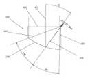
- FIG. 4is a side sectional view of an exemplary optical system showing light rays.
- FIG. 5is a side view of another exemplary optical system.
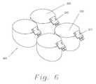
- FIG. 6is an isometric view of an exemplary array of optical systems.
- Various embodiments of the present inventiondisclose systems that control the direction and angle of a light output.
- the output of the systemsreduces power consumption by directing a very high percentage of light generated by one or more LEDs specifically to the object designated to be lighted.
- an optical system 200includes an LED assembly 210 that is coupled to a light pipe 220 . It will be understood by those skilled in the art that the type and size of the LED assembly 210 may vary with the particular optical system to be used in a given application.
- the LED assembly 210is shown with a heat sink plate 230 that conducts heat from an LED die 310 (see FIG. 3 ).
- the LED die 310is generally depicted in the several figures of the drawing as a single element, the LED die 310 may be formed from multiple dies. When multiple dies are used to form the LED die 310 , the multiple dies may be bonded together.
- Light pipe 220may be implemented at least in part as a tube lined with a reflective material, an optical fiber, a hollow light guide, a fluorescence based system, and/or another device suitable for transporting light.
- the light pipe 220may be coupled to the LED die 310 , which may in turn be coupled to the heat sink plate 230 .
- the light pipe 220may be optically coupled to the emitting surface of the LED die 310 .
- the LED assembly 210may be constructed so that there is a narrow air gap between the LED die 310 and a first end of the light pipe 220 .
- a second end of the light pipe 220may be optically coupled to an optic element 240 .
- the optic element 240may be cylindrical in cross section. The optical coupling of the light pipe 220 with the LED die 310 and the optic element 240 reduces light losses at the ends of the light pipe 220 .
- Light traveling within the light pipe 220may travel within a range from approximately +42 degrees to approximately ⁇ 42 degrees relative to the centerline of the light pipe 220 .
- the actual angle of the light travelwill depend on the index of refraction of the light pipe 220 and the specific output of the LED die 310 .
- the light pipe 220conducts light to the optic element 240 .
- the optic element 240may be cylindrical in cross section, but other shapes may also be utilized.
- the optic element 240may or may not have the same index of refraction as the light pipe 220 .
- the optic element 240may have a much greater index of refraction than the index of refraction of air, which is very close to 1.
- the index of refraction for acrylicis approximately 1.49 and for polycarbonate it is approximately 1.58.
- Some plasticshave a higher refractive index, and glass materials may have much higher indexes of refraction.
- the higher the index of refraction of the material used to form the optic element 240the narrower the cone angle of the light relative to a light pipe centerline 410 (see FIG. 4 ).
- the cone anglewould be approximately ⁇ 39 degrees.
- light from the LED assembly 210 that is directed along the light pipe centerline 410will continue in that same direction when the light enters the optic element 240 .
- the lightwill eventually intersect an internal reflective surface 250 .
- the reflective surface 250would be parabolic.
- the shape of the internal reflective surface 250may be varied according to the desired characteristics of the output beam.
- the output beammay be collimated, but different types of output beams may be desired.
- the reflective surface 250may be ellipsoidal or aspheric to provide different effects for the output beam.
- the reflective surface 250creates an internal reflection effect in the optic element 240 .
- Reflective surface 250may be formed by coating the surface of the optic element 240 with a high reflectance material.
- the high reflectance materialmay be, for example, silver, aluminum, or a high performance interference coating.
- the selection of the specific material for the coating appropriate to the applicationis an engineering decision that takes into account the requirements of a particular application and the budget constraints of the project.
- intersection of the light pipe centerline 410 with the reflective surface 250may be near the midpoint of the reflective surface 250 . Constructing the system 200 so that the centerline 410 is near the midpoint of reflective surface 250 maximizes the amount of light that impinges on the reflective surface 250 .
- the cone angle of the light exiting the light pipewould be in the range ⁇ 90 degrees.
- the large cone anglewould be a result of light being refracted at an output surface of the light pipe.
- a large cone anglewould also result if the light pipe was made of acrylic and the non-high refractive index optic element was a hollow element filled with air.
- the geometry of the optical system 200may be such that the light enters the optic element 240 near where light exits the optic element 240 .
- the angle between an output centerline 430 and the light pipe centerline 410may be minimal.
- the smaller the angle between the two centerlines 410 , 430the less difference there is between the length of a positive internal ray 440 , a ray with a positive angle from the light pipe centerline 410 , and the length of a negative internal ray 450 , a ray with a negative angle from the light pipe centerline 410 .
- the length and geometry of the rays 440 , 450determine the output beam cone angle by their geometry. Reducing the angle between the light pipe centerline 410 and the output centerline 430 may reduce the size of the system 200 . The greater the angle between the light pipe centerline 410 and the output centerline 430 , the larger the system 200 may be to achieve the same output beam cone angle.
- the optical lengthsmay vary from nominal approximately ⁇ 30%. If the angle between the two centerlines 410 , 430 were much greater, for example 60 degrees, the differences in the nominal lengths would be closer to approximately ⁇ 60%. To maintain the same output beam cone angle the reflector would need to be much larger in overall size.
- the higher the index of refraction of the optic element 240the more compact the system 200 may be.
- the smaller the angle between the centerlines 410 , 430the more compact the system 200 may be.
- the light exiting the high refractive index optic element 240 at the output surface 420may be refracted so that the light past the output surface 420 may have a greater cone angle than light within the optic element 240 .
- the output surface 420may be flat.
- the output surface 420may also have other geometries.
- the geometry of the output surface 420may be selected based on the overall system requirements and the lighting effect desired.
- Other optic elementsmay be added to the system 200 downstream of the output surface 420 .
- the light pipe 220may be eliminated from the optical system 200 .
- the LED assembly 210may be directly optically coupled to the optic element 240 .
- the optical performance of the system 200may be maintained by reducing the size of the heat sink plate 230 , or reconfiguring the heat sink plate 230 . If the light pipe 230 is used, the length of the light pipe 220 is dependent on the size of the LED assembly 210 and its heat sink plate 230 .
- FIG. 5illustrates a side view of another exemplary optical system 500 .
- the LED die 510is located within an output light path.
- the centerlines of the input light path and the output light pathare coincident, and the angle between them is zero.
- This configurationtherefore may yield a system 500 of minimal size. Electricity and heat must be conducted to and from the LED 510 . If the conducting components are large, they can absorb a significant amount of light. Therefore, high power systems might generally not be configured with LEDs in the output path.
- FIG. 6illustrates an isometric view of an exemplary array 600 of optical systems 200 .
- the array 600may be used for systems in which a large amount of light is required, such as a high powered searchlight.
- heat dissipationmay be made simpler.
- the depth of an array 600 of optical systems 200may be less than that required for an equivalent system using a single large LED or optic element. It will be recognized by those skilled in the art that the array 600 may be implemented in any of the configurations described herein.
Landscapes
- Engineering & Computer Science (AREA)
- General Engineering & Computer Science (AREA)
- Physics & Mathematics (AREA)
- General Physics & Mathematics (AREA)
- Optics & Photonics (AREA)
- Non-Portable Lighting Devices Or Systems Thereof (AREA)
- Led Device Packages (AREA)
Abstract
Description
Claims (20)
Priority Applications (2)
| Application Number | Priority Date | Filing Date | Title |
|---|---|---|---|
| US12/949,642US8733982B2 (en) | 2009-11-18 | 2010-11-18 | Internal collecting reflector optics for LEDs |
| US13/710,930US20130100664A1 (en) | 2009-11-18 | 2012-12-11 | Internal collecting reflector optics for leds |
Applications Claiming Priority (2)
| Application Number | Priority Date | Filing Date | Title |
|---|---|---|---|
| US28154409P | 2009-11-18 | 2009-11-18 | |
| US12/949,642US8733982B2 (en) | 2009-11-18 | 2010-11-18 | Internal collecting reflector optics for LEDs |
Related Child Applications (1)
| Application Number | Title | Priority Date | Filing Date |
|---|---|---|---|
| US13/710,930ContinuationUS20130100664A1 (en) | 2009-11-18 | 2012-12-11 | Internal collecting reflector optics for leds |
Publications (2)
| Publication Number | Publication Date |
|---|---|
| US20110116284A1 US20110116284A1 (en) | 2011-05-19 |
| US8733982B2true US8733982B2 (en) | 2014-05-27 |
Family
ID=44011192
Family Applications (2)
| Application Number | Title | Priority Date | Filing Date |
|---|---|---|---|
| US12/949,642Expired - Fee RelatedUS8733982B2 (en) | 2009-11-18 | 2010-11-18 | Internal collecting reflector optics for LEDs |
| US13/710,930AbandonedUS20130100664A1 (en) | 2009-11-18 | 2012-12-11 | Internal collecting reflector optics for leds |
Family Applications After (1)
| Application Number | Title | Priority Date | Filing Date |
|---|---|---|---|
| US13/710,930AbandonedUS20130100664A1 (en) | 2009-11-18 | 2012-12-11 | Internal collecting reflector optics for leds |
Country Status (6)
| Country | Link |
|---|---|
| US (2) | US8733982B2 (en) |
| EP (1) | EP2501990A4 (en) |
| JP (1) | JP2013511811A (en) |
| KR (1) | KR20120095437A (en) |
| CN (1) | CN102713421A (en) |
| WO (1) | WO2011063145A1 (en) |
Cited By (2)
| Publication number | Priority date | Publication date | Assignee | Title |
|---|---|---|---|---|
| US10739513B2 (en) | 2018-08-31 | 2020-08-11 | RAB Lighting Inc. | Apparatuses and methods for efficiently directing light toward and away from a mounting surface |
| US10801679B2 (en) | 2018-10-08 | 2020-10-13 | RAB Lighting Inc. | Apparatuses and methods for assembling luminaires |
Families Citing this family (6)
| Publication number | Priority date | Publication date | Assignee | Title |
|---|---|---|---|---|
| WO2013009221A2 (en) | 2011-07-14 | 2013-01-17 | Gorlinskiy Bronislav Vladislavovich | Light-emitting diode lamp |
| WO2013152234A1 (en)* | 2012-04-04 | 2013-10-10 | Axlen, Inc. | Optically efficient solid-state lighting device packaging |
| US20140092590A1 (en)* | 2012-10-01 | 2014-04-03 | Rambus Delaware Llc | Led flashlight |
| US9696008B2 (en)* | 2013-07-02 | 2017-07-04 | Cooper Technologies Company | Reflector for directed beam LED illumination |
| GB201315241D0 (en) | 2013-08-27 | 2013-10-09 | Nano Lit Technologies Ltd | Improvements in or relating to lighting |
| PL241098B1 (en)* | 2017-09-29 | 2022-08-01 | Akademia Im Jana Dlugosza W Czestochowie | Optical collimator for detection of ultraweak luminescence of spatially expanded objects, using the single-channel detector |
Citations (112)
| Publication number | Priority date | Publication date | Assignee | Title |
|---|---|---|---|---|
| US223898A (en) | 1879-11-04 | 1880-01-27 | Thomas Alva Edison | Electric lamp |
| GB663840A (en) | 1946-12-18 | 1951-12-27 | Edgar Gretener | A regulable optical illumination system |
| US2673923A (en) | 1947-12-03 | 1954-03-30 | Duro Test Corp | Means for producing colored light beams |
| US2971083A (en) | 1958-11-14 | 1961-02-07 | Gen Electric | Low brightness louver |
| US4171874A (en) | 1975-02-03 | 1979-10-23 | General Electric Company | Evenly illuminated display devices |
| US4172631A (en) | 1975-01-07 | 1979-10-30 | Izon Corporation | Parallel optical fiber and strip illuminating arrays |
| US4392187A (en) | 1981-03-02 | 1983-07-05 | Vari-Lite, Ltd. | Computer controlled lighting system having automatically variable position, color, intensity and beam divergence |
| US4420796A (en) | 1981-02-24 | 1983-12-13 | Kei Mori | Device for dispersing light rays issuing from a light guide |
| US4431966A (en) | 1981-05-12 | 1984-02-14 | Sangamo Weston, Inc. | Modular backlighted analog/digital instrument display |
| US4487481A (en) | 1980-03-24 | 1984-12-11 | Epson Corporation | Backlighted liquid crystal display |
| US4566935A (en) | 1984-07-31 | 1986-01-28 | Texas Instruments Incorporated | Spatial light modulator and method |
| US4596992A (en) | 1984-08-31 | 1986-06-24 | Texas Instruments Incorporated | Linear spatial light modulator and printer |
| US4615595A (en) | 1984-10-10 | 1986-10-07 | Texas Instruments Incorporated | Frame addressed spatial light modulator |
| US4662746A (en) | 1985-10-30 | 1987-05-05 | Texas Instruments Incorporated | Spatial light modulator and method |
| US4710732A (en) | 1984-07-31 | 1987-12-01 | Texas Instruments Incorporated | Spatial light modulator and method |
| US4737896A (en) | 1985-07-23 | 1988-04-12 | Canon Kabushiki Kaisha | Illumination device |
| US4936659A (en) | 1989-01-26 | 1990-06-26 | Rockwell International Corporation | Liquid crystal display brightness enhancer |
| US4956619A (en) | 1988-02-19 | 1990-09-11 | Texas Instruments Incorporated | Spatial light modulator |
| US4972306A (en) | 1989-01-23 | 1990-11-20 | Vari-Lite, Inc. | Compact variable diffuser for use in a luminaire |
| US4974122A (en) | 1989-03-28 | 1990-11-27 | Rockwell International Corporation | Compact LCD luminaire |
| US5028939A (en) | 1988-08-23 | 1991-07-02 | Texas Instruments Incorporated | Spatial light modulator system |
| US5040098A (en) | 1989-04-13 | 1991-08-13 | Fujitsu Limited | Backlight for an electronic display |
| US5046826A (en) | 1987-09-19 | 1991-09-10 | Canon Kabushiki Kaisha | Illuminator and display panel employing the illuminator |
| US5057974A (en) | 1990-06-22 | 1991-10-15 | Tatsuji Mizobe | System for uniformly illuminating liquid crystal display board from rear side |
| US5083252A (en) | 1990-04-19 | 1992-01-21 | Tailored Lighting Company, Inc. | Apparatus for producing light distributions |
| US5126886A (en) | 1989-04-10 | 1992-06-30 | Morpheus Lights, Inc. | Scrolling primary color changer |
| US5217285A (en) | 1991-03-15 | 1993-06-08 | The United States Of America As Represented By United States Department Of Energy | Apparatus for synthesis of a solar spectrum |
| US5221987A (en) | 1992-04-10 | 1993-06-22 | Laughlin Richard H | FTIR modulator |
| US5319491A (en) | 1990-08-10 | 1994-06-07 | Continental Typographics, Inc. | Optical display |
| US5359691A (en) | 1992-10-08 | 1994-10-25 | Briteview Technologies | Backlighting system with a multi-reflection light injection system and using microprisms |
| US5396350A (en) | 1993-11-05 | 1995-03-07 | Alliedsignal Inc. | Backlighting apparatus employing an array of microprisms |
| US5414599A (en) | 1991-09-09 | 1995-05-09 | Enplas Corporation | Surface light source device |
| US5467208A (en) | 1992-06-01 | 1995-11-14 | Sharp Kabushiki Kaisha | Liquid crystal display |
| US5528720A (en) | 1992-03-23 | 1996-06-18 | Minnesota Mining And Manufacturing Co. | Tapered multilayer luminaire devices |
| CN1147070A (en) | 1995-09-13 | 1997-04-09 | 康松高 | Optical system of projector with optical aberration compensation lens |
| US5631895A (en) | 1994-10-18 | 1997-05-20 | Nec Corporation | Optical information recording medium |
| US5825548A (en) | 1997-09-11 | 1998-10-20 | Vari-Lite, Inc. | Cross-fading color filter and system |
| US5936772A (en) | 1997-04-16 | 1999-08-10 | Oympus Optical Co., Ltd. | Light source optical system for endoscopes |
| US5953469A (en) | 1996-10-29 | 1999-09-14 | Xeotron Corporation | Optical device utilizing optical waveguides and mechanical light-switches |
| US5995690A (en) | 1996-11-21 | 1999-11-30 | Minnesota Mining And Manufacturing Company | Front light extraction film for light guiding systems and method of manufacture |
| US6040937A (en) | 1994-05-05 | 2000-03-21 | Etalon, Inc. | Interferometric modulation |
| US6048081A (en) | 1998-06-15 | 2000-04-11 | Richardson; Brian Edward | Beam divergence and shape controlling module for projected light |
| JP2000252525A (en) | 1999-02-26 | 2000-09-14 | Iwasaki Electric Co Ltd | Light emitting diode lamp |
| US6167182A (en) | 1996-10-25 | 2000-12-26 | Omron Corporation | Surface light source device and liquid crystal display device, portable telephone and information terminal employing the surface light source device |
| US6350041B1 (en) | 1999-12-03 | 2002-02-26 | Cree Lighting Company | High output radial dispersing lamp using a solid state light source |
| US20020031294A1 (en) | 1998-01-20 | 2002-03-14 | Takashi Takeda | Optical switching device and image display device |
| US6360033B1 (en) | 1999-11-25 | 2002-03-19 | Electronics And Telecommunications Research Institute | Optical switch incorporating therein shallow arch leaf springs |
| US20020044720A1 (en) | 2000-10-17 | 2002-04-18 | Brophy Christopher P. | System for aligning connectors and optical devices |
| EP1215526A1 (en) | 2000-07-11 | 2002-06-19 | Mitsubishi Chemical Corporation | Surface light source device |
| US6421104B1 (en) | 1999-10-22 | 2002-07-16 | Motorola, Inc. | Front illuminator for a liquid crystal display and method of making same |
| US6421103B2 (en) | 1999-12-28 | 2002-07-16 | Fuji Photo Film Co., Ltd. | Liquid-crystal display apparatus including a backlight section using collimating plate |
| US20020105709A1 (en) | 1997-09-04 | 2002-08-08 | Whitehead Lorne A. | Optical switching by controllable frustration of total internal reflection |
| JP2002223006A (en) | 2001-01-26 | 2002-08-09 | Toyoda Gosei Co Ltd | Reflection type light emitting diode |
| JP2002229017A (en) | 2001-02-07 | 2002-08-14 | Sharp Corp | Display device |
| US6438283B1 (en) | 1999-10-08 | 2002-08-20 | Optical Switch Corporation | Frustrated total internal reflection switch using double pass reflection and method of operation |
| US6502961B1 (en) | 2000-11-20 | 2003-01-07 | Brian Edward Richardson | Conical lens array to control projected light beam color, divergence, and shape |
| EP1291833A2 (en) | 2001-09-06 | 2003-03-12 | Ngk Insulators, Ltd. | Display system with cooling device |
| JP2003115204A (en) | 2001-10-04 | 2003-04-18 | Toyoda Gosei Co Ltd | Shading reflection type device and light source |
| US6565233B1 (en) | 1999-08-17 | 2003-05-20 | Brian Edward Richardson | Color, size and distribution module for projected light |
| US6674562B1 (en) | 1994-05-05 | 2004-01-06 | Iridigm Display Corporation | Interferometric modulation of radiation |
| US20040076396A1 (en) | 2001-02-14 | 2004-04-22 | Yoshinori Suga | Light guiding body, light reflective sheet, surface light source device and liquid crystal display device using the light reflective sheet, and method of manufacturing the light reflective sheet |
| US6729734B2 (en) | 2002-04-01 | 2004-05-04 | Hewlett-Packard Development Company, L.P. | System for enhancing the quality of an image |
| US20040109105A1 (en) | 2002-11-29 | 2004-06-10 | Alps Electric Co., Ltd. | Backlight unit and liquid crystal display device |
| US6768572B2 (en) | 1997-10-29 | 2004-07-27 | Teloptics Corporation | Solid state free space switch array on a substrate |
| US6771325B1 (en) | 1999-11-05 | 2004-08-03 | Texas Instruments Incorporated | Color recapture for display systems |
| WO2004068183A2 (en) | 2003-01-27 | 2004-08-12 | 3M Innovative Properties Company | Phosphor based light sources having an polymeric long pass reflector |
| US6824270B2 (en) | 2002-08-29 | 2004-11-30 | Samsung Electronics Co., Ltd. | Single-panel color image display apparatus and scrolling method |
| US20050018147A1 (en) | 2003-06-10 | 2005-01-27 | Samsung Electronics Co., Ltd. | Compact LED module and projection display adopting the same |
| US20050057731A1 (en) | 2003-09-17 | 2005-03-17 | Young-Chol Lee | Projection display |
| US6924945B1 (en) | 2003-10-28 | 2005-08-02 | Brian Edward Richardson | Compact light collection system with improved efficiency and reduced size |
| WO2005071310A1 (en) | 2004-01-21 | 2005-08-04 | Fresnel Optics Gmbh | System for illuminating large areas in an even or defined manner |
| US20050201100A1 (en)* | 2003-09-08 | 2005-09-15 | Cassarly William J. | Led lighting assembly |
| US20050207177A1 (en) | 2004-03-18 | 2005-09-22 | Guy James K | Remote source lighting |
| US20050221473A1 (en) | 2004-03-30 | 2005-10-06 | Intel Corporation | Sensor array integrated circuits |
| US20050243570A1 (en) | 2004-04-23 | 2005-11-03 | Chaves Julio C | Optical manifold for light-emitting diodes |
| US20050248827A1 (en) | 2002-03-01 | 2005-11-10 | Starkweather Gary K | Reflective microelectrical mechanical structure (MEMS) optical modulator and optical display system |
| CN1701446A (en) | 2002-08-30 | 2005-11-23 | 吉尔科有限公司 | LED flat light sources and low-profile headlights constructed from them |
| US20050270796A1 (en) | 2004-06-07 | 2005-12-08 | Mitsubishi Denki Kabushiki Kaisha | Planar light source device and display device using the same |
| US6974232B1 (en) | 2003-10-14 | 2005-12-13 | Brian Edward Richardson | Compact lighting system with improved light transmission and color filters |
| US6991355B1 (en)* | 2004-06-16 | 2006-01-31 | Osram Sylvania Inc. | light emitting diode lamp with light pipes |
| US20060070379A1 (en) | 2000-10-31 | 2006-04-06 | Microsoft Corporation | Microelectrical mechanical structure (MEMS) optical modulator and optical display system |
| US7080932B2 (en) | 2004-01-26 | 2006-07-25 | Philips Lumileds Lighting Company, Llc | LED with an optical system to increase luminance by recycling emitted light |
| JP2006241249A (en) | 2005-03-01 | 2006-09-14 | Dowa Mining Co Ltd | Phosphor mixture and light emitting device |
| US7123216B1 (en) | 1994-05-05 | 2006-10-17 | Idc, Llc | Photonic MEMS and structures |
| US7142744B2 (en) | 2001-05-14 | 2006-11-28 | Calient Networks | Wavelength power equalization by attenuation in an optical switch |
| US7144131B2 (en) | 2004-09-29 | 2006-12-05 | Advanced Optical Technologies, Llc | Optical system using LED coupled with phosphor-doped reflective materials |
| US7177498B2 (en) | 2002-03-13 | 2007-02-13 | Altera Corporation | Two-by-two optical routing element using two-position MEMS mirrors |
| US20070133224A1 (en) | 1995-06-27 | 2007-06-14 | Parker Jeffery R | Light emitting panel assemblies |
| US20070176887A1 (en) | 2006-01-31 | 2007-08-02 | Uehara Shin-Ichi | Display device, terminal device, and display panel |
| US20070211487A1 (en) | 2004-09-20 | 2007-09-13 | Koninklijke Philips Electronics, N.V. | Led collimator element with a semiparabolic reflector |
| US7345824B2 (en) | 2002-03-26 | 2008-03-18 | Trivium Technologies, Inc. | Light collimating device |
| WO2008060335A1 (en) | 2006-11-17 | 2008-05-22 | Rensselaer Polytechnic Institute | High-power white leds and manufacturing method thereof |
| US7380962B2 (en) | 2004-04-23 | 2008-06-03 | Light Prescriptions Innovators, Llc | Optical manifold for light-emitting diodes |
| US20080247169A1 (en) | 2004-03-16 | 2008-10-09 | Koninklijke Philips Electronics, N.V. | High Brightness Illumination Device With Incoherent Solid State Light Source |
| US7447397B1 (en) | 2004-06-14 | 2008-11-04 | Dynamic Method Enterprises Limited | Optical switch matrix |
| US7445360B2 (en)* | 2004-09-02 | 2008-11-04 | Patlite Corporation | Lens component, indicator unit for signal indicating light, and signal indicating light |
| DE102007030186A1 (en) | 2007-06-27 | 2009-01-02 | Harald Hofmann | Linear LED lamp |
| WO2009024952A2 (en) | 2007-08-23 | 2009-02-26 | Koninklijke Philips Electronics N.V. | Light source including reflective wavelength-converting layer |
| US7499206B1 (en) | 2005-12-09 | 2009-03-03 | Brian Edward Richardson | TIR light valve |
| US20090064993A1 (en) | 2007-09-10 | 2009-03-12 | Banyan Energy, Inc. | Solar energy concentrator |
| EP2045633A1 (en) | 2007-10-04 | 2009-04-08 | Samsung Electronics Co., Ltd. | All-in-one type light guide plate with protrusions of inverted truncated prisms and backlight apparatus employing the same |
| JP2009087850A (en) | 2007-10-02 | 2009-04-23 | Ritsumeikan | Lighting device |
| US20090262368A1 (en) | 2008-04-18 | 2009-10-22 | Avago Technologies Ecbu Ip (Singapore) Pte. Ltd. | Light pipe for low profile optical navigation systems |
| JP2009244693A (en) | 2008-03-31 | 2009-10-22 | Alpine Electronics Inc | Liquid crystal display device |
| CN101644386A (en) | 2009-06-11 | 2010-02-10 | 江苏名家汇电器有限公司 | LED light fitting based on DMD micro-lens optical design |
| US20100085773A1 (en) | 2009-01-02 | 2010-04-08 | Brian Edward Richardson | Optic system light guide with controlled output |
| US20100172138A1 (en) | 2009-01-02 | 2010-07-08 | Brian Edward Richardson | Tir switched flat panel display |
| US20100220492A1 (en) | 2009-06-11 | 2010-09-02 | Brian Edward Richardson | Optical system with reflectors and light pipes |
| US20100315802A1 (en) | 2009-06-11 | 2010-12-16 | Brian Edward Richardson | Optical system for a Light Emitting Diode with collection, conduction, phosphor directing, and output means |
| US20100315836A1 (en) | 2009-06-11 | 2010-12-16 | Brian Edward Richardson | Flat panel optical display system with highly controlled output |
| US20110222309A1 (en) | 2008-11-18 | 2011-09-15 | Yashuhiro KOIKE | Optical element and light-emitting device |
| US20120120676A1 (en) | 2010-11-12 | 2012-05-17 | Richardson Brian E | Lighting assembly with asymmetrical light ray angle distribution |
Family Cites Families (7)
| Publication number | Priority date | Publication date | Assignee | Title |
|---|---|---|---|---|
| US517285A (en)* | 1894-03-27 | marberger | ||
| US2238898A (en)* | 1938-06-07 | 1941-04-22 | Greenstein Oscar | Intaglio printing machine for manufacturing name markers |
| JPH1041551A (en)* | 1996-07-26 | 1998-02-13 | Toyoda Gosei Co Ltd | Light emitting diode lamp assembly |
| US6578989B2 (en)* | 2000-09-29 | 2003-06-17 | Omron Corporation | Optical device for an optical element and apparatus employing the device |
| JP2005038822A (en)* | 2003-06-26 | 2005-02-10 | Sharp Corp | Lighting device for flat panel display and light emitting lamp |
| JP4747726B2 (en)* | 2004-09-09 | 2011-08-17 | 豊田合成株式会社 | Light emitting device |
| US9279046B2 (en)* | 2009-06-08 | 2016-03-08 | Board Of Trustees Of Michigan State University | Nanocomposites and nanocomposite foams and methods and products related to same |
- 2010
- 2010-11-18KRKR1020127015792Apatent/KR20120095437A/ennot_activeCeased
- 2010-11-18JPJP2012540060Apatent/JP2013511811A/enactivePending
- 2010-11-18CNCN2010800524401Apatent/CN102713421A/enactivePending
- 2010-11-18USUS12/949,642patent/US8733982B2/ennot_activeExpired - Fee Related
- 2010-11-18EPEP10832199.3Apatent/EP2501990A4/ennot_activeWithdrawn
- 2010-11-18WOPCT/US2010/057273patent/WO2011063145A1/enactiveApplication Filing
- 2012
- 2012-12-11USUS13/710,930patent/US20130100664A1/ennot_activeAbandoned
Patent Citations (119)
| Publication number | Priority date | Publication date | Assignee | Title |
|---|---|---|---|---|
| US223898A (en) | 1879-11-04 | 1880-01-27 | Thomas Alva Edison | Electric lamp |
| GB663840A (en) | 1946-12-18 | 1951-12-27 | Edgar Gretener | A regulable optical illumination system |
| US2673923A (en) | 1947-12-03 | 1954-03-30 | Duro Test Corp | Means for producing colored light beams |
| US2971083A (en) | 1958-11-14 | 1961-02-07 | Gen Electric | Low brightness louver |
| US4172631A (en) | 1975-01-07 | 1979-10-30 | Izon Corporation | Parallel optical fiber and strip illuminating arrays |
| US4171874A (en) | 1975-02-03 | 1979-10-23 | General Electric Company | Evenly illuminated display devices |
| US4487481A (en) | 1980-03-24 | 1984-12-11 | Epson Corporation | Backlighted liquid crystal display |
| US4618216A (en) | 1980-03-24 | 1986-10-21 | Seiko Epson Kabushiki Kaisha | Backlighted liquid crystal display using light passage member for more nearly uniform illumination |
| US4420796A (en) | 1981-02-24 | 1983-12-13 | Kei Mori | Device for dispersing light rays issuing from a light guide |
| US4392187A (en) | 1981-03-02 | 1983-07-05 | Vari-Lite, Ltd. | Computer controlled lighting system having automatically variable position, color, intensity and beam divergence |
| US4431966A (en) | 1981-05-12 | 1984-02-14 | Sangamo Weston, Inc. | Modular backlighted analog/digital instrument display |
| US4710732A (en) | 1984-07-31 | 1987-12-01 | Texas Instruments Incorporated | Spatial light modulator and method |
| US4566935A (en) | 1984-07-31 | 1986-01-28 | Texas Instruments Incorporated | Spatial light modulator and method |
| US4596992A (en) | 1984-08-31 | 1986-06-24 | Texas Instruments Incorporated | Linear spatial light modulator and printer |
| US4615595A (en) | 1984-10-10 | 1986-10-07 | Texas Instruments Incorporated | Frame addressed spatial light modulator |
| US4737896A (en) | 1985-07-23 | 1988-04-12 | Canon Kabushiki Kaisha | Illumination device |
| US4662746A (en) | 1985-10-30 | 1987-05-05 | Texas Instruments Incorporated | Spatial light modulator and method |
| US5046826A (en) | 1987-09-19 | 1991-09-10 | Canon Kabushiki Kaisha | Illuminator and display panel employing the illuminator |
| US4956619A (en) | 1988-02-19 | 1990-09-11 | Texas Instruments Incorporated | Spatial light modulator |
| US5028939A (en) | 1988-08-23 | 1991-07-02 | Texas Instruments Incorporated | Spatial light modulator system |
| US4972306A (en) | 1989-01-23 | 1990-11-20 | Vari-Lite, Inc. | Compact variable diffuser for use in a luminaire |
| US4936659A (en) | 1989-01-26 | 1990-06-26 | Rockwell International Corporation | Liquid crystal display brightness enhancer |
| US4974122A (en) | 1989-03-28 | 1990-11-27 | Rockwell International Corporation | Compact LCD luminaire |
| US5126886A (en) | 1989-04-10 | 1992-06-30 | Morpheus Lights, Inc. | Scrolling primary color changer |
| US5040098A (en) | 1989-04-13 | 1991-08-13 | Fujitsu Limited | Backlight for an electronic display |
| US5083252A (en) | 1990-04-19 | 1992-01-21 | Tailored Lighting Company, Inc. | Apparatus for producing light distributions |
| US5057974A (en) | 1990-06-22 | 1991-10-15 | Tatsuji Mizobe | System for uniformly illuminating liquid crystal display board from rear side |
| US5319491A (en) | 1990-08-10 | 1994-06-07 | Continental Typographics, Inc. | Optical display |
| US5217285A (en) | 1991-03-15 | 1993-06-08 | The United States Of America As Represented By United States Department Of Energy | Apparatus for synthesis of a solar spectrum |
| US5414599A (en) | 1991-09-09 | 1995-05-09 | Enplas Corporation | Surface light source device |
| US5528720A (en) | 1992-03-23 | 1996-06-18 | Minnesota Mining And Manufacturing Co. | Tapered multilayer luminaire devices |
| US5221987A (en) | 1992-04-10 | 1993-06-22 | Laughlin Richard H | FTIR modulator |
| US5467208A (en) | 1992-06-01 | 1995-11-14 | Sharp Kabushiki Kaisha | Liquid crystal display |
| US5359691A (en) | 1992-10-08 | 1994-10-25 | Briteview Technologies | Backlighting system with a multi-reflection light injection system and using microprisms |
| US5396350A (en) | 1993-11-05 | 1995-03-07 | Alliedsignal Inc. | Backlighting apparatus employing an array of microprisms |
| US6040937A (en) | 1994-05-05 | 2000-03-21 | Etalon, Inc. | Interferometric modulation |
| US7123216B1 (en) | 1994-05-05 | 2006-10-17 | Idc, Llc | Photonic MEMS and structures |
| US6674562B1 (en) | 1994-05-05 | 2004-01-06 | Iridigm Display Corporation | Interferometric modulation of radiation |
| US6867896B2 (en) | 1994-05-05 | 2005-03-15 | Idc, Llc | Interferometric modulation of radiation |
| US5631895A (en) | 1994-10-18 | 1997-05-20 | Nec Corporation | Optical information recording medium |
| US20070133224A1 (en) | 1995-06-27 | 2007-06-14 | Parker Jeffery R | Light emitting panel assemblies |
| CN1147070A (en) | 1995-09-13 | 1997-04-09 | 康松高 | Optical system of projector with optical aberration compensation lens |
| US6167182A (en) | 1996-10-25 | 2000-12-26 | Omron Corporation | Surface light source device and liquid crystal display device, portable telephone and information terminal employing the surface light source device |
| US5953469A (en) | 1996-10-29 | 1999-09-14 | Xeotron Corporation | Optical device utilizing optical waveguides and mechanical light-switches |
| US5995690A (en) | 1996-11-21 | 1999-11-30 | Minnesota Mining And Manufacturing Company | Front light extraction film for light guiding systems and method of manufacture |
| US5936772A (en) | 1997-04-16 | 1999-08-10 | Oympus Optical Co., Ltd. | Light source optical system for endoscopes |
| US20020105709A1 (en) | 1997-09-04 | 2002-08-08 | Whitehead Lorne A. | Optical switching by controllable frustration of total internal reflection |
| US5825548A (en) | 1997-09-11 | 1998-10-20 | Vari-Lite, Inc. | Cross-fading color filter and system |
| US6768572B2 (en) | 1997-10-29 | 2004-07-27 | Teloptics Corporation | Solid state free space switch array on a substrate |
| US20020031294A1 (en) | 1998-01-20 | 2002-03-14 | Takashi Takeda | Optical switching device and image display device |
| US6048081A (en) | 1998-06-15 | 2000-04-11 | Richardson; Brian Edward | Beam divergence and shape controlling module for projected light |
| JP2000252525A (en) | 1999-02-26 | 2000-09-14 | Iwasaki Electric Co Ltd | Light emitting diode lamp |
| US6565233B1 (en) | 1999-08-17 | 2003-05-20 | Brian Edward Richardson | Color, size and distribution module for projected light |
| US6438283B1 (en) | 1999-10-08 | 2002-08-20 | Optical Switch Corporation | Frustrated total internal reflection switch using double pass reflection and method of operation |
| US6421104B1 (en) | 1999-10-22 | 2002-07-16 | Motorola, Inc. | Front illuminator for a liquid crystal display and method of making same |
| US6771325B1 (en) | 1999-11-05 | 2004-08-03 | Texas Instruments Incorporated | Color recapture for display systems |
| US6360033B1 (en) | 1999-11-25 | 2002-03-19 | Electronics And Telecommunications Research Institute | Optical switch incorporating therein shallow arch leaf springs |
| US6350041B1 (en) | 1999-12-03 | 2002-02-26 | Cree Lighting Company | High output radial dispersing lamp using a solid state light source |
| US6421103B2 (en) | 1999-12-28 | 2002-07-16 | Fuji Photo Film Co., Ltd. | Liquid-crystal display apparatus including a backlight section using collimating plate |
| EP1215526A1 (en) | 2000-07-11 | 2002-06-19 | Mitsubishi Chemical Corporation | Surface light source device |
| US20020044720A1 (en) | 2000-10-17 | 2002-04-18 | Brophy Christopher P. | System for aligning connectors and optical devices |
| US20060070379A1 (en) | 2000-10-31 | 2006-04-06 | Microsoft Corporation | Microelectrical mechanical structure (MEMS) optical modulator and optical display system |
| US6502961B1 (en) | 2000-11-20 | 2003-01-07 | Brian Edward Richardson | Conical lens array to control projected light beam color, divergence, and shape |
| JP2002223006A (en) | 2001-01-26 | 2002-08-09 | Toyoda Gosei Co Ltd | Reflection type light emitting diode |
| JP2002229017A (en) | 2001-02-07 | 2002-08-14 | Sharp Corp | Display device |
| US20040076396A1 (en) | 2001-02-14 | 2004-04-22 | Yoshinori Suga | Light guiding body, light reflective sheet, surface light source device and liquid crystal display device using the light reflective sheet, and method of manufacturing the light reflective sheet |
| US7142744B2 (en) | 2001-05-14 | 2006-11-28 | Calient Networks | Wavelength power equalization by attenuation in an optical switch |
| EP1291833A2 (en) | 2001-09-06 | 2003-03-12 | Ngk Insulators, Ltd. | Display system with cooling device |
| JP2003115204A (en) | 2001-10-04 | 2003-04-18 | Toyoda Gosei Co Ltd | Shading reflection type device and light source |
| US20050248827A1 (en) | 2002-03-01 | 2005-11-10 | Starkweather Gary K | Reflective microelectrical mechanical structure (MEMS) optical modulator and optical display system |
| US7177498B2 (en) | 2002-03-13 | 2007-02-13 | Altera Corporation | Two-by-two optical routing element using two-position MEMS mirrors |
| US7345824B2 (en) | 2002-03-26 | 2008-03-18 | Trivium Technologies, Inc. | Light collimating device |
| US6729734B2 (en) | 2002-04-01 | 2004-05-04 | Hewlett-Packard Development Company, L.P. | System for enhancing the quality of an image |
| US6824270B2 (en) | 2002-08-29 | 2004-11-30 | Samsung Electronics Co., Ltd. | Single-panel color image display apparatus and scrolling method |
| CN1701446A (en) | 2002-08-30 | 2005-11-23 | 吉尔科有限公司 | LED flat light sources and low-profile headlights constructed from them |
| US20040109105A1 (en) | 2002-11-29 | 2004-06-10 | Alps Electric Co., Ltd. | Backlight unit and liquid crystal display device |
| WO2004068183A2 (en) | 2003-01-27 | 2004-08-12 | 3M Innovative Properties Company | Phosphor based light sources having an polymeric long pass reflector |
| US20050018147A1 (en) | 2003-06-10 | 2005-01-27 | Samsung Electronics Co., Ltd. | Compact LED module and projection display adopting the same |
| US20050201100A1 (en)* | 2003-09-08 | 2005-09-15 | Cassarly William J. | Led lighting assembly |
| US20050057731A1 (en) | 2003-09-17 | 2005-03-17 | Young-Chol Lee | Projection display |
| US6974232B1 (en) | 2003-10-14 | 2005-12-13 | Brian Edward Richardson | Compact lighting system with improved light transmission and color filters |
| US6924945B1 (en) | 2003-10-28 | 2005-08-02 | Brian Edward Richardson | Compact light collection system with improved efficiency and reduced size |
| WO2005071310A1 (en) | 2004-01-21 | 2005-08-04 | Fresnel Optics Gmbh | System for illuminating large areas in an even or defined manner |
| US7080932B2 (en) | 2004-01-26 | 2006-07-25 | Philips Lumileds Lighting Company, Llc | LED with an optical system to increase luminance by recycling emitted light |
| US20080247169A1 (en) | 2004-03-16 | 2008-10-09 | Koninklijke Philips Electronics, N.V. | High Brightness Illumination Device With Incoherent Solid State Light Source |
| US6971781B2 (en)* | 2004-03-18 | 2005-12-06 | The Boeing Company | Remote source lighting |
| US20050207177A1 (en) | 2004-03-18 | 2005-09-22 | Guy James K | Remote source lighting |
| US20050221473A1 (en) | 2004-03-30 | 2005-10-06 | Intel Corporation | Sensor array integrated circuits |
| US7286296B2 (en) | 2004-04-23 | 2007-10-23 | Light Prescriptions Innovators, Llc | Optical manifold for light-emitting diodes |
| US7380962B2 (en) | 2004-04-23 | 2008-06-03 | Light Prescriptions Innovators, Llc | Optical manifold for light-emitting diodes |
| US20080170296A1 (en) | 2004-04-23 | 2008-07-17 | Light Prescriptions Innovators, Llc | Optical devices |
| US20050243570A1 (en) | 2004-04-23 | 2005-11-03 | Chaves Julio C | Optical manifold for light-emitting diodes |
| US20050270796A1 (en) | 2004-06-07 | 2005-12-08 | Mitsubishi Denki Kabushiki Kaisha | Planar light source device and display device using the same |
| US7447397B1 (en) | 2004-06-14 | 2008-11-04 | Dynamic Method Enterprises Limited | Optical switch matrix |
| US6991355B1 (en)* | 2004-06-16 | 2006-01-31 | Osram Sylvania Inc. | light emitting diode lamp with light pipes |
| US7445360B2 (en)* | 2004-09-02 | 2008-11-04 | Patlite Corporation | Lens component, indicator unit for signal indicating light, and signal indicating light |
| US20070211487A1 (en) | 2004-09-20 | 2007-09-13 | Koninklijke Philips Electronics, N.V. | Led collimator element with a semiparabolic reflector |
| US7144131B2 (en) | 2004-09-29 | 2006-12-05 | Advanced Optical Technologies, Llc | Optical system using LED coupled with phosphor-doped reflective materials |
| JP2006241249A (en) | 2005-03-01 | 2006-09-14 | Dowa Mining Co Ltd | Phosphor mixture and light emitting device |
| US7499206B1 (en) | 2005-12-09 | 2009-03-03 | Brian Edward Richardson | TIR light valve |
| US20100328748A1 (en) | 2005-12-09 | 2010-12-30 | Brian Edward Richardson | TIR Light Valve |
| US20090116099A1 (en) | 2005-12-09 | 2009-05-07 | Brian Edward Richardson | Tir light valve |
| US20070176887A1 (en) | 2006-01-31 | 2007-08-02 | Uehara Shin-Ichi | Display device, terminal device, and display panel |
| WO2008060335A1 (en) | 2006-11-17 | 2008-05-22 | Rensselaer Polytechnic Institute | High-power white leds and manufacturing method thereof |
| DE102007030186A1 (en) | 2007-06-27 | 2009-01-02 | Harald Hofmann | Linear LED lamp |
| WO2009024952A2 (en) | 2007-08-23 | 2009-02-26 | Koninklijke Philips Electronics N.V. | Light source including reflective wavelength-converting layer |
| US20090064993A1 (en) | 2007-09-10 | 2009-03-12 | Banyan Energy, Inc. | Solar energy concentrator |
| JP2009087850A (en) | 2007-10-02 | 2009-04-23 | Ritsumeikan | Lighting device |
| EP2045633A1 (en) | 2007-10-04 | 2009-04-08 | Samsung Electronics Co., Ltd. | All-in-one type light guide plate with protrusions of inverted truncated prisms and backlight apparatus employing the same |
| JP2009244693A (en) | 2008-03-31 | 2009-10-22 | Alpine Electronics Inc | Liquid crystal display device |
| US20090262368A1 (en) | 2008-04-18 | 2009-10-22 | Avago Technologies Ecbu Ip (Singapore) Pte. Ltd. | Light pipe for low profile optical navigation systems |
| US20110222309A1 (en) | 2008-11-18 | 2011-09-15 | Yashuhiro KOIKE | Optical element and light-emitting device |
| US20100085773A1 (en) | 2009-01-02 | 2010-04-08 | Brian Edward Richardson | Optic system light guide with controlled output |
| US20100172138A1 (en) | 2009-01-02 | 2010-07-08 | Brian Edward Richardson | Tir switched flat panel display |
| US20100220492A1 (en) | 2009-06-11 | 2010-09-02 | Brian Edward Richardson | Optical system with reflectors and light pipes |
| US20100315802A1 (en) | 2009-06-11 | 2010-12-16 | Brian Edward Richardson | Optical system for a Light Emitting Diode with collection, conduction, phosphor directing, and output means |
| US20100315836A1 (en) | 2009-06-11 | 2010-12-16 | Brian Edward Richardson | Flat panel optical display system with highly controlled output |
| CN101644386A (en) | 2009-06-11 | 2010-02-10 | 江苏名家汇电器有限公司 | LED light fitting based on DMD micro-lens optical design |
| US20120120676A1 (en) | 2010-11-12 | 2012-05-17 | Richardson Brian E | Lighting assembly with asymmetrical light ray angle distribution |
Non-Patent Citations (24)
| Title |
|---|
| Decision on Petition to Make Special under the Green Technology Pilot Program (Dismissed) with mail date of Feb. 22, 2010, re U.S. Appl. No. 12/319,172. |
| Decision on Petition to Make Special under the Green Technology Pilot Program (Dismissed) with mail date of Jul. 13, 2010, re U.S. Appl. No. 12/319,172. |
| Decision on Petition to Make Special under the Green Technology Program (Denied) with mail date of Aug. 27, 2010, re U.S. Appl. No. 12/319,172. |
| Decision on Petition to Make Special under the Green Technology Program (Denied) with mail date of Oct. 14, 2010, re U.S. Appl. No. 12/319,172. |
| EP Search Report dated Feb. 21, 2014 in EP Application No. 10832199.3. 6 pages. |
| Information Disclosure Statement with mail date of Mar. 24, 2010. re U.S. Appl. No. 12/319,172. |
| Information Disclosure Statement with mail date of Sep. 8, 2010, re U.S. Appl. No. 12/319,171. |
| Information Disclosure Statement with mail date of Sep. 8, 2010, re U.S. Appl. No. 12/319,172. |
| International Preliminary Report on Patentability dated May 31, 2012 re Int'l Application No. PCT/US10/057273. |
| International Search Report and the Written Opinion with mail date of Feb. 18, 2011, re Int'l Application No. PCT/US2010/001673. |
| International Search Report and the Written Opinion with mail date of Feb. 7, 2011, re Int'l Application No. PCT/US2010/001661. |
| International Search Report and the Written Opinion with mail date of Mar. 4, 2011, re Int'l Application No. PCT/US2010/001674. |
| International Search Report and the Written Opinion with mail date of Sep. 13, 2010, re Int'l. Application No. PCT/US2009/006763. |
| International Search Report and Written Opinion dated Nov. 28, 2012 in International Application No. PCT/US2012/037250. |
| Non-Final Office Action with mail date of Oct. 21, 2010, re U.S. Appl. No. 12/319,172. |
| Preliminary Amendment with mail date of Apr. 12, 2010, re U.S. Appl. No. 12/319,172. |
| Preliminary Amendment with mail date of Aug. 13, 2010, re U.S. Appl. No. 12/319,172. |
| Preliminary Amendment with mail date of Sep. 7, 2010, re U.S. Appl. No. 12/319,172. |
| Renewed Petition for Green Tech Pilot Program with mail date of Aug. 13, 2010, re U.S. Appl. No. 12/319,172. |
| Renewed Petition for Green Tech Pilot Program with mail date of Jun. 10, 2010, re U.S. Appl. No. 12/319,172. |
| Renewed Petition for Green Technology Pilot Program with mail date of Sep. 7, 2010, re U.S. Appl. No. 12/319,172. |
| Response to Office Action of Oct. 21, 2010 with mail date of Mar. 21, 2011, re U.S. Appl. No. 12/319,172. |
| Statement of Special Status in Support of Petition to Make Special under the Green Technology Pilot Program with mail date of Dec. 22, 2009, re U.S. Appl. No. 12/319,172. |
| Statement of Special Status in Support of Petition to Make Special under the Green Technology Pilot Program with mail date of Oct. 22, 2010, re U.S. Appl. No. 12/319,172. |
Cited By (2)
| Publication number | Priority date | Publication date | Assignee | Title |
|---|---|---|---|---|
| US10739513B2 (en) | 2018-08-31 | 2020-08-11 | RAB Lighting Inc. | Apparatuses and methods for efficiently directing light toward and away from a mounting surface |
| US10801679B2 (en) | 2018-10-08 | 2020-10-13 | RAB Lighting Inc. | Apparatuses and methods for assembling luminaires |
Also Published As
| Publication number | Publication date |
|---|---|
| EP2501990A1 (en) | 2012-09-26 |
| US20110116284A1 (en) | 2011-05-19 |
| EP2501990A4 (en) | 2014-03-26 |
| CN102713421A (en) | 2012-10-03 |
| US20130100664A1 (en) | 2013-04-25 |
| KR20120095437A (en) | 2012-08-28 |
| JP2013511811A (en) | 2013-04-04 |
| WO2011063145A1 (en) | 2011-05-26 |
Similar Documents
| Publication | Publication Date | Title |
|---|---|---|
| US8733982B2 (en) | Internal collecting reflector optics for LEDs | |
| US6814470B2 (en) | Highly efficient LED lamp | |
| US8702292B2 (en) | Linear illumination devices having light guides and LED-based illumination modules | |
| US6899443B2 (en) | Light module | |
| US6902291B2 (en) | In-pavement directional LED luminaire | |
| US8106568B2 (en) | Lighting device capable of suppressing occurrence of ovelap of multiple shades | |
| US20100296283A1 (en) | Total internal reflective (tir) optic light assembly | |
| JP6106872B2 (en) | Bulk-type lens, light emitter using the same, and illumination device | |
| KR101194308B1 (en) | Wide-angle illuminator | |
| CN212510961U (en) | Vehicle lamps | |
| US20120106190A1 (en) | Light guide focussing device and method | |
| US20050135109A1 (en) | Light blade | |
| US8439520B2 (en) | Color-configurable lighting assembly | |
| US8496355B2 (en) | Reflector element of lighting unit | |
| CN212986806U (en) | Achromatic light-emitting device | |
| US6796677B1 (en) | High intensity lamp | |
| KR102358707B1 (en) | LED lamp for ceiling and LED lamp lens | |
| CN101749571A (en) | Light source module | |
| CN212986801U (en) | Lighting device and lamp | |
| CN213299988U (en) | Light mixing lens with absorption cover | |
| RU51169U1 (en) | LED HEADLIGHT | |
| CN209782512U (en) | Optics and Lighting | |
| KR20240111040A (en) | Optical system for headlamp of vehicle minimizing the height of lens | |
| CN114001296A (en) | Total reflection lampshade and LED tunnel lamp | |
| CN113915582A (en) | Vehicle lamp |
Legal Events
| Date | Code | Title | Description |
|---|---|---|---|
| AS | Assignment | Owner name:IMAGINE ILLUMINATION, LLC, CALIFORNIA Free format text:ASSIGNMENT OF ASSIGNORS INTEREST;ASSIGNORS:RICHARDSON, BRIAN E.;RICHARDSON, EILEEN H.;IMAGINE DESIGNS, INC.;REEL/FRAME:026137/0717 Effective date:20101223 Owner name:RAMBUS INTERNATIONAL LTD., CAYMAN ISLANDS Free format text:ASSIGNMENT OF ASSIGNORS INTEREST;ASSIGNOR:IMAGINE ILLUMINATION, LLC;REEL/FRAME:026137/0778 Effective date:20101223 | |
| FEPP | Fee payment procedure | Free format text:PAT HOLDER NO LONGER CLAIMS SMALL ENTITY STATUS, ENTITY STATUS SET TO UNDISCOUNTED (ORIGINAL EVENT CODE: STOL); ENTITY STATUS OF PATENT OWNER: LARGE ENTITY | |
| AS | Assignment | Owner name:RAMBUS DELAWARE, OHIO Free format text:ASSIGNMENT OF ASSIGNORS INTEREST;ASSIGNOR:RAMBUS INC.;REEL/FRAME:029967/0165 Effective date:20121001 | |
| STCF | Information on status: patent grant | Free format text:PATENTED CASE | |
| AS | Assignment | Owner name:RAMBUS DELAWARE LLC, OHIO Free format text:ASSIGNMENT OF ASSIGNORS INTEREST;ASSIGNOR:RAMBUS INTERNATIONAL LTD.;REEL/FRAME:033881/0001 Effective date:20121001 | |
| MAFP | Maintenance fee payment | Free format text:PAYMENT OF MAINTENANCE FEE, 4TH YEAR, LARGE ENTITY (ORIGINAL EVENT CODE: M1551) Year of fee payment:4 | |
| FEPP | Fee payment procedure | Free format text:MAINTENANCE FEE REMINDER MAILED (ORIGINAL EVENT CODE: REM.); ENTITY STATUS OF PATENT OWNER: LARGE ENTITY | |
| LAPS | Lapse for failure to pay maintenance fees | Free format text:PATENT EXPIRED FOR FAILURE TO PAY MAINTENANCE FEES (ORIGINAL EVENT CODE: EXP.); ENTITY STATUS OF PATENT OWNER: LARGE ENTITY | |
| STCH | Information on status: patent discontinuation | Free format text:PATENT EXPIRED DUE TO NONPAYMENT OF MAINTENANCE FEES UNDER 37 CFR 1.362 | |
| FP | Lapsed due to failure to pay maintenance fee | Effective date:20220527 |