US8733564B2 - Variable configuration shelving apparatus and methods - Google Patents
Variable configuration shelving apparatus and methodsDownload PDFInfo
- Publication number
- US8733564B2 US8733564B2US12/829,746US82974610AUS8733564B2US 8733564 B2US8733564 B2US 8733564B2US 82974610 AUS82974610 AUS 82974610AUS 8733564 B2US8733564 B2US 8733564B2
- Authority
- US
- United States
- Prior art keywords
- shelf
- beams
- flange
- edge
- supporting
- Prior art date
- Legal status (The legal status is an assumption and is not a legal conclusion. Google has not performed a legal analysis and makes no representation as to the accuracy of the status listed.)
- Active, expires
Links
- 238000000034methodMethods0.000titledescription3
- 230000002441reversible effectEffects0.000claimsdescription8
- 238000010276constructionMethods0.000description3
- 238000005096rolling processMethods0.000description2
- 230000001419dependent effectEffects0.000description1
- 230000014759maintenance of locationEffects0.000description1
- 239000000463materialSubstances0.000description1
- 238000012986modificationMethods0.000description1
- 230000004048modificationEffects0.000description1
- 239000002245particleSubstances0.000description1
- 239000002023woodSubstances0.000description1
Images


Classifications
- A—HUMAN NECESSITIES
- A47—FURNITURE; DOMESTIC ARTICLES OR APPLIANCES; COFFEE MILLS; SPICE MILLS; SUCTION CLEANERS IN GENERAL
- A47B—TABLES; DESKS; OFFICE FURNITURE; CABINETS; DRAWERS; GENERAL DETAILS OF FURNITURE
- A47B96/00—Details of cabinets, racks or shelf units not covered by a single one of groups A47B43/00 - A47B95/00; General details of furniture
- A47B96/06—Brackets or similar supporting means for cabinets, racks or shelves
- A—HUMAN NECESSITIES
- A47—FURNITURE; DOMESTIC ARTICLES OR APPLIANCES; COFFEE MILLS; SPICE MILLS; SUCTION CLEANERS IN GENERAL
- A47B—TABLES; DESKS; OFFICE FURNITURE; CABINETS; DRAWERS; GENERAL DETAILS OF FURNITURE
- A47B57/00—Cabinets, racks or shelf units, characterised by features for adjusting shelves or partitions
- A47B57/30—Cabinets, racks or shelf units, characterised by features for adjusting shelves or partitions with means for adjusting the height of detachable shelf supports
- A47B57/48—Cabinets, racks or shelf units, characterised by features for adjusting shelves or partitions with means for adjusting the height of detachable shelf supports consisting of tongues, pins or similar projecting means coacting with openings
- A47B57/50—Cabinets, racks or shelf units, characterised by features for adjusting shelves or partitions with means for adjusting the height of detachable shelf supports consisting of tongues, pins or similar projecting means coacting with openings characterised by shape or orientation of opening, e.g. keyhole-shaped
- A—HUMAN NECESSITIES
- A47—FURNITURE; DOMESTIC ARTICLES OR APPLIANCES; COFFEE MILLS; SPICE MILLS; SUCTION CLEANERS IN GENERAL
- A47B—TABLES; DESKS; OFFICE FURNITURE; CABINETS; DRAWERS; GENERAL DETAILS OF FURNITURE
- A47B96/00—Details of cabinets, racks or shelf units not covered by a single one of groups A47B43/00 - A47B95/00; General details of furniture
- A47B96/14—Bars, uprights, struts, or like supports, for cabinets, brackets, or the like
- A47B96/1441—Horizontal struts
- Y—GENERAL TAGGING OF NEW TECHNOLOGICAL DEVELOPMENTS; GENERAL TAGGING OF CROSS-SECTIONAL TECHNOLOGIES SPANNING OVER SEVERAL SECTIONS OF THE IPC; TECHNICAL SUBJECTS COVERED BY FORMER USPC CROSS-REFERENCE ART COLLECTIONS [XRACs] AND DIGESTS
- Y10—TECHNICAL SUBJECTS COVERED BY FORMER USPC
- Y10T—TECHNICAL SUBJECTS COVERED BY FORMER US CLASSIFICATION
- Y10T29/00—Metal working
- Y10T29/49—Method of mechanical manufacture
- Y10T29/49826—Assembling or joining
Definitions
- a fully flat shelf surface with no upstanding edge lipmay be useful in one application where it is desired to easily slide, load or unload an item onto or from the surface without obstruction from an upstanding lip.
- variable shelf apparatushaving a variety of shelf configurations easily presented and capable of providing all the application varieties above, but without the need to supply extra or additional shelves for each desired configuration or application.
- a further objective of the inventionhas been to provide an improved shelving apparatus and methods capable of presenting a variety of shelf configurations.
- a preferred embodiment of the inventioncontemplates provision of a shelving apparatus wherein the shelves are of identical construction and further including a plurality of shelf supporting beams which are mounted to shelf-supporting columns in different orientations to present, in combination with the shelves, a variety of shelf configurations.
- a variety of shelf configurationsare rendered possible, not by variations in shelf structures, but by variable orientation of shelf supporting beams, which alternately define upstanding lips along predetermined shelf edges or which support the shelf without any upstanding lip above the plane of the shelf surface.
- the inventionprovides a shelf apparatus comprising a plurality of shelves, common shelf-supporting but reversible beams and shelf-supporting columns wherein the shelf configuration is defined or determined by the orientation of the common but reversible beams.
- the inventioncontemplates an improved shelf supporting beam having a shelf supporting flange extending from the beam body at a position which is nearer one elongated edge of the beam than another.
- the beam flangeWhen oriented in one position, supports a shelf such that the upper edge of the beam is generally flush with the shelf surface.
- the beam flangeWhen oriented in a second or reverse position, supports the shelf on another side thereof, with an edge of the beam extending above the shelf surface, defining a lip along the adjacent edge of the shelf.
- a usercan then select which if any shelf edge needs or does not need a lip and then provide that lip, or not, by orienting the position of the adjacent shelf beam between the columns.
- a shelving apparatusis thus presented to provide a variety of shelf configurations accomplished by common components and without additional shelving necessary to provide a desired shelf configuration.
- a unique shelf-supporting and reversible beam structureis also contemplated.
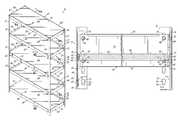
- FIG. 1is an isometric view of a shelving apparatus according to the invention
- FIG. 2is an exploded isometric view of the invention illustrating a shelf or two shelf-supporting beams wherein the top edges of the beams are flush with the shelf surface;
- FIG. 3is an isometric view of a shelf-supporting beam according to the invention.
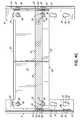
- FIG. 4Ais a cross-sectional view taken along lines 4 A- 4 A of FIG. 1 ;
- FIG. 4Bis a cross-sectional view taken along lines 4 B- 4 B of FIG. 1 ;
- FIG. 4Cis a cross-sectional view taken along lines 4 C- 4 C of FIG. 1 ;
- FIG. 4Dis a cross-sectional view taken along lines 4 D- 4 D of FIG. 1 ;
- FIG. 5Ais an illustrative cross-section of a shelf-supporting beam wherein the top edge 30 of the beam is flush with the flat edge surface;
- FIG. 5Bis an illustrative cross-section of a shelf-supporting beam, wherein the beam is flipped over, or reversed, the shelf residing on the opposite side of the support flange and the now upper beam edge extending above a shelf surface, forming an upstanding lip or edge for the shelf.
- Apparatus 10includes four upstanding shelf-supporting columns 11 - 14 .
- Apparatus 10also includes in this embodiment five shelves 16 - 20 of preferably identical construction.
- Shelves 16 - 20may be made of wood, particle board, synthetics, laminates or any suitable materials and preferably having a thickness 22 (illustrated at FIG. 2 ).
- Apparatus 10further includes a set of four shelf-supporting beams 24 - 27 , including a front beam 24 , side beams 25 , 26 and rear beam 27 , for each respective shelf 16 - 20 .
- Front and rear beam 24 , 27are essentially the same length, while side beams 25 , 26 are shorter than beams 24 , 27 , but are equal in length to each other.
- each beam 24 - 27is preferably similar in construction to each other beam (excepting beam length as noted above), they are oriented in apparatus 10 in different configurations as herein noted.
- FIG. 3clearly illustrates the features common to each of preferred beams 24 , 27 , which are the same (excepting length) as in beams 25 , 26 .
- Each beam 24 - 27thus has a top edge 30 , a bottom edge 32 , and a beam web 34 .
- Web 34has a reversely-folded flange 36 and a shelf-supporting flange 38 extending perpendicularly therefrom.
- Top edge 30is defined by the folded juncture of web 34 and reverse flange 36 .
- Shelf-support flange 38has an upper shelf-support surface 40 ( FIG. 3 ) and an opposite lower shelf-support surface 42 ( FIGS. 4A-4D ) on another side of flange 38 .
- Like portions of the beams 24 - 27carry like numbers for clarity.
- the beams 24 - 27preferably have holes 44 to accommodate beam-to-column interconnection rivets 46 as will be discussed.
- Holes 48may be placed in flange 38 for accommodating appropriate fasteners (not shown) for respective shelves 16 - 20 .
- columns 11 - 14are in the configuration or an angle with two column flanges joined at ninety degrees.
- Each column flangeis provided with a series of spaced apart, keyhole-shaped apertures 50 , each having an enlarged portion 51 and a narrower portion 52 (see FIG. 4A , for example).
- the series of apertures 50preferably run the length of the respective columns 11 - 14 and it will be noted the narrower portions 52 are beneath the enlarged portions 51 when the columns are vertically oriented in an assembled unit 10 .
- Enlarged portions 51are of a size to allow passage of the head 47 of a rivet 56 , while the narrower portion 52 accommodates the shank 48 of rivets 46 (see FIGS. 4A-4D ) but does not allow withdrawal of the head 47 therethrough.
- Head 47is larger in periphery than can be passed thru narrow portion 52 .
- Apertures 50are spaced apart preferably at the same distance as holes 44 in beams 24 - 27 , or in some multiple or fraction thereof, such that rivets 46 in the beams 24 - 27 index with respective holes 50 in the columns 11 - 14 , thus securing the respective beams 24 - 27 to respective columns 11 - 14 as will be described.
- top shelf 16presents an upper flat surface as shown with respective sides 60 - 63 .
- Shelf 16is a flat surface 64 with no upstanding lip above that surface 64 , sides 60 - 63 being flush with surface 64 .
- Sides 60 - 63are flush since top edge 30 of the beams 24 - 27 do not extend above surface 64 .
- shelf 17is also defined by a similar flat surface 64 , however, that surface is surrounded at its four sides by upstanding lips defined by the edge 32 of front side and rear beams 24 - 27 extending above the plane of surface 64 of shelf 17 . In that configuration, items on surface 64 of shelf 17 are prevented from sliding or rolling off shelf 17 .
- shelf 18it too has a flat shelf surface 64 .
- the two side and rear edges of shelf 18are surrounded by upstanding lips defined by top edges 32 of the two side beams 25 , 26 and the rear beam 27 .
- the front edge of shelf 17i.e. top edge 30 of front beam 24 , is flush with surface 64 , allowing easy loading of shelf 18 .
- Shelf 19 and beams 24 - 27are configured as shelf 17 , simply illustrating that apparatus 10 can be configured in a variety of different ways, the configuration of each shelf being selectable.
- shelf 20is yet again different.
- This shelfalso has a flat shelf surface 64 .
- the front and both side edges thereofare defined by top edge 30 of each beam 24 , 25 , 26 being flush with surface 64 , but with edge 32 of reversed rear beam 27 extending above surface 64 to prevent loads from being moved over the rear edge of the shelf.
- FIG. 1illustrates but one of a large number of variable shelf configurations and combinations thereof.
- Top shelf 16has flush edges with no upstanding lips
- shelf 17has an upstanding lip around all four shelf edges
- shelf 18has an upstanding lip around the two sides and one rear edge
- shelf 19is like shelf 17 and shelf 20 has flush front and side edges with an upstanding lip along its rear edge.
- Apparatus 10might include a plurality of shelves, all with the same edge or lip configuration (i.e. beam orientation), all with different edge or lip configurations or any selected combination thereof.
- FIGS. 2-5clearly illustrate components of the invention which facilitate and provide these varied configurations.
- the upstanding or flush lips or edgesare determined by the orientation of the respective beams 24 - 27 for each shelf.
- each beam 24 - 27has flange 38 which is disposed closer to top edge 30 than to the bottom edge 32 .
- Top surface 40 of flange 38is spaced from the top edge 30 a distance which is approximately the same as the thickness of a shelf to be supported there (see FIG. 2 and the shelf thickness 22 , for example). Accordingly, when a shelf 16 - 20 is supported on surface 40 of flange 38 , top edge 30 of the respective beam is flush, with, or in approximately the same plane as surface 64 of the shelf.
- the top edge of beam 24 - 27flush with surface 64 , defines or provides a flush edge for that side, front or back sides or edges of the shelf.
- the flange 38is spaced further from lower beam edge 32 than top beam edge 30 . Accordingly, where the beam is reversed, flipped or rotated upside down from its position in FIG. 3 , the lower surface 42 of flange 38 now becomes the shelf-supporting surface of the flange 38 . In such an orientation, the shelf surface 64 is significantly lower than upper edge 32 of the beam so that a portion of the beam extends above surface 64 , forming an upstanding lip or edge of the shelf edge therealong.
- Rivets 46 in beams 24 - 27are indexable with apertures 50 in columns 11 - 14 respectively, so that each individual beam can be supported by a column at a predetermined orientation, either upright with a top beam edge 30 or flipped over so that beam edge 32 is the uppermost edge and edge 30 the lowermost.
- beam edge 30is uppermost, any adjacent portion of a shelf supported on surface 40 of flange 38 is flush with top edge 30 , thus defining a flush shelf edge with no lip therealong.
- the shelfis supported on surface 42 of flange 38 so beam edge 32 extends above shelf surface 64 , defining an upstanding lip above surface 64 .
- the respective shelves 16 - 20are typically flat, the flush edges or upstanding lip edges being provided by the orientation of the beam along the adjacent shelf portion.
- FIGS. 4A-4Dportions of the apparatus 10 and shelves 16 , 17 , 18 and 20 are illustrated for further understanding.
- FIG. 4Aillustrates the front beam 24 , rear beam 27 and side beam 26 , all mounted on columns 11 , 14 to provide a shelf 16 with no upstanding lips, but rather flush edges.
- Rivets 46hold beams 24 , 26 , 27 on the respective column with top edges 30 higher than lower edge 32 .
- Shelf 16is supported on respective upper surfaces 40 of flanges 38 . In this configuration, all beams are similarly oriented. It will be appreciated that the beams are introduced to the columns with rivet heads 47 extending through enlarged portions 51 of apertures 50 . The rivet shanks are lowered into narrow portions 52 to secure the respective beam onto a column.
- FIG. 4Billustrates a cross-section of shelf 17 wherein each beam is flipped with edge 32 uppermost, and edge 30 lowermost, the beams defining an upstanding lip around the entire shelf on front, sides and rear thereof. The extent of the lip is defined by the distance between shelf surface 64 and beam edge 32 .
- FIG. 4Cillustrate a cross-section of shelf 18 wherein there is a lip along both the sides and the rear of shelf 18 .
- the side beam 25 , 26 and rear beam 27are flipped or oriented so the beam edges 32 are uppermost compared to beam edge 30 which is lowermost.
- Shelf 18is supported on surfaces 42 of flanges 38 of beams 25 , 26 , 27 .
- front beam 24is oriented with its edge 30 uppermost, and shelf 18 lies on surface 40 of flange 38 .
- shelf surface 64is below all beam edges 32 and flush with beam edge 30 of beam 24 , leaving a front shelf side with no lip, and shelf sides and back with an upstanding lip.
- FIG. 4Dillustrates a cross-section of shelf 20 where the rear side of shelf 20 has an upstanding lip, but the front and rear sides have no lip.
- shelf 20is supported on surface 42 of flange 38 of beam 27 , but on surfaces 40 of flanges 38 of beams 24 , 25 , 26 .
- the length of beams 24 - 27is such that while the respective beam ends are functionally coupled to the respective columns 11 - 14 , the beams 24 - 27 do not interfere one with the other, regardless of their orientation.
- FIGS. 5A , 5 Bare illustrative of the two varied configurations of a beam with respect to a shelf.
- the configuration of the shelf edges being flush or with upstanding lipsis dependent on the orientation of the common side beams and common front and rear beams and not on the shelves 16 - 20 themselves.
- the inventionfacilitates that configuration with only the same number of parts (columns, shelves and beams) as if the desired configurations were all identical.
- a shelf in the inventionhas a flush edge configuration when the shelf side or portion is alongside a beam in a first position, as in FIGS. 2 and 3 . That same shelf has a lipped edge configuration along a portion thereof adjacent a beam which is in a reversed second position, such as the beams 24 , 27 in FIG. 4B .
- the inventioncontemplates methods of assembling a shelf apparatus wherein columns are erected vertically, front side and rear bears of a set of beams are connected to respective columns in one of two reversible positions, such that beams in one position have an upper edge flush with a shelf surface when a shelf is laid thereon, and when the beams are reversed, the now upper bottom edge extends above a surface of a shelf laid on the beam to provide an upstanding lip above the shelf surface. Any combination of beam orientations can be used to provide a lip for a shelf edge or a flush shelf edge.
Landscapes
- Assembled Shelves (AREA)
Abstract
Description
Claims (9)
Priority Applications (3)
| Application Number | Priority Date | Filing Date | Title |
|---|---|---|---|
| US12/829,746US8733564B2 (en) | 2010-07-02 | 2010-07-02 | Variable configuration shelving apparatus and methods |
| AU2011201493AAU2011201493B2 (en) | 2010-07-02 | 2011-04-01 | Variable configuration shelving apparatus and methods |
| US14/250,964US9101216B2 (en) | 2010-07-02 | 2014-04-11 | Variable configuration shelving apparatus and method |
Applications Claiming Priority (1)
| Application Number | Priority Date | Filing Date | Title |
|---|---|---|---|
| US12/829,746US8733564B2 (en) | 2010-07-02 | 2010-07-02 | Variable configuration shelving apparatus and methods |
Related Child Applications (1)
| Application Number | Title | Priority Date | Filing Date |
|---|---|---|---|
| US14/250,964DivisionUS9101216B2 (en) | 2010-07-02 | 2014-04-11 | Variable configuration shelving apparatus and method |
Publications (2)
| Publication Number | Publication Date |
|---|---|
| US20120000873A1 US20120000873A1 (en) | 2012-01-05 |
| US8733564B2true US8733564B2 (en) | 2014-05-27 |
Family
ID=45398898
Family Applications (2)
| Application Number | Title | Priority Date | Filing Date |
|---|---|---|---|
| US12/829,746Active2031-02-06US8733564B2 (en) | 2010-07-02 | 2010-07-02 | Variable configuration shelving apparatus and methods |
| US14/250,964ActiveUS9101216B2 (en) | 2010-07-02 | 2014-04-11 | Variable configuration shelving apparatus and method |
Family Applications After (1)
| Application Number | Title | Priority Date | Filing Date |
|---|---|---|---|
| US14/250,964ActiveUS9101216B2 (en) | 2010-07-02 | 2014-04-11 | Variable configuration shelving apparatus and method |
Country Status (2)
| Country | Link |
|---|---|
| US (2) | US8733564B2 (en) |
| AU (1) | AU2011201493B2 (en) |
Cited By (11)
| Publication number | Priority date | Publication date | Assignee | Title |
|---|---|---|---|---|
| US20140116973A1 (en)* | 2012-10-29 | 2014-05-01 | Whirlpool Corporation | Rack shelving unit |
| US20140284294A1 (en)* | 2013-03-22 | 2014-09-25 | Silverack, Llc | Shelving Support Bracket for a Storage Rack |
| US9854906B1 (en)* | 2016-06-16 | 2018-01-02 | Chia-Nan Ke | Shelving structure |
| US10299593B2 (en)* | 2016-04-28 | 2019-05-28 | Witron Logistik + Informatik Gmbh | Rack, load carrier and method of production |
| US20190290000A1 (en)* | 2018-02-15 | 2019-09-26 | Hercke LLC | Shelving unit |
| US10806257B1 (en)* | 2020-02-12 | 2020-10-20 | Taiwan Shin Yeh Enterprise Co., Ltd. | Wire shelving assembly |
| USD942784S1 (en)* | 2019-10-08 | 2022-02-08 | Brian Burge | Table |
| US20220071388A1 (en)* | 2020-09-08 | 2022-03-10 | Grillnetics LLC | Enclosure Assembly System |
| US20230129296A1 (en)* | 2021-10-27 | 2023-04-27 | Edsal Manufacturing Company, Llc | Weldless shelf support beams and shelving units utilizing same |
| US20250040699A1 (en)* | 2023-07-31 | 2025-02-06 | Taiwan Shin Yeh Enterprise Co., Ltd. | Shelf device |
| US12310495B2 (en)* | 2021-10-27 | 2025-05-27 | Edsal Manufacturing Company, Llc | Weldless shelf support beams and shelving units utilizing same |
Families Citing this family (27)
| Publication number | Priority date | Publication date | Assignee | Title |
|---|---|---|---|---|
| US8172098B2 (en)* | 2008-05-06 | 2012-05-08 | Rapid Rack Industries, Inc. | Modular rack assembly |
| USD686430S1 (en)* | 2010-07-02 | 2013-07-23 | Edsal Manufacturing Co., Inc. | Shelf |
| USD742150S1 (en) | 2010-07-02 | 2015-11-03 | Edsal Manufacturing Company, Inc. | Wire shelving |
| US9415240B2 (en)* | 2011-10-21 | 2016-08-16 | Accuray Incorporated | Apparatus for generating multi-energy x-ray images and methods of using the same |
| US8875445B2 (en)* | 2012-10-29 | 2014-11-04 | Stephen Lee Lippert | Light weight modular units for staggered stacked building system |
| US9351427B2 (en)* | 2013-12-17 | 2016-05-24 | Chatsworth Products, Inc. | Electronic equipment enclosure |
| US10799022B2 (en) | 2014-11-19 | 2020-10-13 | Hangzhou Great Star Industrial Co., Ltd. | Connecting structure, connecting method and article containing such connecting structure |
| KR101807350B1 (en)* | 2014-11-19 | 2017-12-08 | 주식회사 엘지화학 | Container for energy storage system |
| CN205271967U (en)* | 2014-11-19 | 2016-06-01 | 杭州巨星科技股份有限公司 | Goods shelves and crossbeam thereof |
| US9713379B1 (en)* | 2016-01-24 | 2017-07-25 | Frank Tsai | Shelf supporting beam configuration for shelving apparatus |
| US9661921B1 (en)* | 2016-02-19 | 2017-05-30 | Frank Tsai | Multiple shelving apparatus |
| US9861198B2 (en)* | 2016-03-30 | 2018-01-09 | Kevin Anderson | Bracket to support a shelf |
| USD799870S1 (en) | 2016-08-01 | 2017-10-17 | Edsal Manufacturing Company, Inc. | Wire rack shelf and Z-beam support |
| US11344114B2 (en)* | 2018-03-12 | 2022-05-31 | Hangzhou United Tools Co., Ltd. | Shelf |
| US10376047B1 (en)* | 2018-03-29 | 2019-08-13 | Ikea Supply Ag | Furniture frame system |
| USD878123S1 (en)* | 2018-11-27 | 2020-03-17 | Edsal Manufacturing Company, Inc. | Shelving unit with color coordinated tote |
| TWM581428U (en)* | 2019-04-19 | 2019-08-01 | 邱武旭 | Laminate shelf structure of display rack |
| CN212474832U (en)* | 2020-04-30 | 2021-02-05 | 青岛蓝山贸易有限公司 | Combined cargo supporting device |
| US20230270248A1 (en)* | 2020-09-16 | 2023-08-31 | Perfect Site LLC | Storage rack |
| US11818860B1 (en) | 2020-12-15 | 2023-11-14 | Chatsworth Products, Inc. | Frame structure for electronic equipment enclosure |
| KR20220147007A (en)* | 2021-04-26 | 2022-11-02 | (주)스피드랙 | Prefabricated angle |
| US12144424B2 (en) | 2021-10-22 | 2024-11-19 | Silicate Studio Home, LLC | Floating shelf bracket |
| US12137805B2 (en) | 2021-10-22 | 2024-11-12 | Silicate Studio Home, LLC | Floating shelf bracket with threaded rods |
| US12011088B2 (en) | 2021-10-22 | 2024-06-18 | Silicate Studio Home LLC | Floating shelf bracket with welded rods |
| CN217261344U (en)* | 2022-02-22 | 2022-08-23 | 青岛福友工具有限公司 | Detachable goods shelf |
| US11825946B1 (en) | 2022-05-25 | 2023-11-28 | Silicate Studio Home, LLC | Modular floating shelf system |
| US20240374029A1 (en)* | 2023-05-12 | 2024-11-14 | Kangyan Group | Support beam and shelving system using the same |
Citations (14)
| Publication number | Priority date | Publication date | Assignee | Title |
|---|---|---|---|---|
| US1288010A (en)* | 1918-07-06 | 1918-12-17 | William Harry Isaac | Shelf-bracket. |
| US1380570A (en)* | 1918-09-21 | 1921-06-07 | Berger Mfg Co | Bar-rack |
| US2788949A (en)* | 1950-10-09 | 1957-04-16 | Henry A Gurries | Shelf construction |
| US3029056A (en)* | 1960-10-27 | 1962-04-10 | Arthur F Breglia | Reversible support means for shelving and the like |
| US3070237A (en)* | 1960-06-30 | 1962-12-25 | Acme Steel Co | Pallet rack |
| US3303937A (en)* | 1964-09-09 | 1967-02-14 | Interlake Steel Corp | Pallet rack |
| US3587483A (en)* | 1968-11-27 | 1971-06-28 | Speedrack Inc | Storage rack beam and storage rack utilizing same |
| US3862691A (en)* | 1973-06-01 | 1975-01-28 | Lear Siegler Inc | Lock span shelving |
| US4342397A (en)* | 1980-09-08 | 1982-08-03 | Halstrick Robert T | Fastenings for storage racks |
| US5011031A (en)* | 1989-08-11 | 1991-04-30 | Konstant Anthony N | Crossbar system for rack |
| US5749481A (en)* | 1994-01-03 | 1998-05-12 | Miller; Myron W. | Storage rack and structural beam therefor |
| US20050103733A1 (en)* | 2003-11-17 | 2005-05-19 | Bruce Saltzberg | Cargo rack |
| US20050103734A1 (en)* | 2003-11-17 | 2005-05-19 | Edsal Manufacturing Co., Inc. | Cargo rack |
| US20110272373A1 (en)* | 2005-01-27 | 2011-11-10 | Edsal Manufacturing Co., Inc. | Outside wrap post coupler with assembly assist |
Family Cites Families (22)
| Publication number | Priority date | Publication date | Assignee | Title |
|---|---|---|---|---|
| US3048245A (en)* | 1960-02-29 | 1962-08-07 | Arean Eastern Ltd | Locking mechanism |
| US3194407A (en)* | 1963-12-10 | 1965-07-13 | Altrui Thomas N D | Convertible storage rack |
| US3294250A (en)* | 1964-03-05 | 1966-12-27 | Aurora Equipment Co | Shelving structure |
| US3346126A (en)* | 1965-06-28 | 1967-10-10 | Bloom Milton | Adjustable rack shelving |
| US3458052A (en)* | 1965-10-21 | 1969-07-29 | Aluminum Extrusions Inc | Structural support arrangement and method of assembling |
| US3392848A (en)* | 1966-06-06 | 1968-07-16 | Interlake Steel Corp | Pallet rack |
| US3545626A (en)* | 1968-05-10 | 1970-12-08 | Edward Seiz | Storage structure |
| US3846944A (en)* | 1970-12-21 | 1974-11-12 | Barton King Syst Corp | Structural self-supporting system |
| US4106630A (en)* | 1977-04-28 | 1978-08-15 | Parsteel Products Company, Inc. | Storage rack assembly |
| US4142638A (en)* | 1977-05-31 | 1979-03-06 | Husky Storage Systems, Inc. | Prefabricated storage shelves |
| US4285436A (en)* | 1978-12-26 | 1981-08-25 | Speedshelf International, Inc. | Integral locking tab for storage racks |
| US4467729A (en)* | 1982-02-19 | 1984-08-28 | Franklyn Featherman | Wide span shelving |
| US4549665A (en)* | 1982-09-03 | 1985-10-29 | Republic Steel Corporation | Shelf assembly |
| US4796541A (en)* | 1987-07-31 | 1989-01-10 | Halstrick Robert T | Storage rack |
| US5289665A (en)* | 1991-09-26 | 1994-03-01 | Higgins Gregory J | Orthogonal framework for modular building systems |
| US5411154A (en)* | 1993-09-13 | 1995-05-02 | Hardy Manufacturing, Inc. | System for joining support members |
| US5350074A (en)* | 1993-10-01 | 1994-09-27 | Morgan Marshall Industries, Inc. | Pallet rack lock |
| US5624045A (en)* | 1995-03-16 | 1997-04-29 | Unarco Material Handling, Inc. | Storage rack having latched beam-to-column connection |
| US5598791A (en)* | 1995-03-27 | 1997-02-04 | Taylor; Alva R. | Shelving apparatus and method of assembly |
| US5979338A (en)* | 1997-05-23 | 1999-11-09 | Salmanson; Jeffrey | Modular low cost pallet and shelf assembly |
| US6726039B2 (en)* | 2001-03-21 | 2004-04-27 | Paul Flum Ideas, Inc. | Inventory control system for walk-in display coolers and the like |
| US6749070B2 (en)* | 2001-07-27 | 2004-06-15 | International Business Machines Corporation | Modular stacking equipment rack |
- 2010
- 2010-07-02USUS12/829,746patent/US8733564B2/enactiveActive
- 2011
- 2011-04-01AUAU2011201493Apatent/AU2011201493B2/ennot_activeCeased
- 2014
- 2014-04-11USUS14/250,964patent/US9101216B2/enactiveActive
Patent Citations (14)
| Publication number | Priority date | Publication date | Assignee | Title |
|---|---|---|---|---|
| US1288010A (en)* | 1918-07-06 | 1918-12-17 | William Harry Isaac | Shelf-bracket. |
| US1380570A (en)* | 1918-09-21 | 1921-06-07 | Berger Mfg Co | Bar-rack |
| US2788949A (en)* | 1950-10-09 | 1957-04-16 | Henry A Gurries | Shelf construction |
| US3070237A (en)* | 1960-06-30 | 1962-12-25 | Acme Steel Co | Pallet rack |
| US3029056A (en)* | 1960-10-27 | 1962-04-10 | Arthur F Breglia | Reversible support means for shelving and the like |
| US3303937A (en)* | 1964-09-09 | 1967-02-14 | Interlake Steel Corp | Pallet rack |
| US3587483A (en)* | 1968-11-27 | 1971-06-28 | Speedrack Inc | Storage rack beam and storage rack utilizing same |
| US3862691A (en)* | 1973-06-01 | 1975-01-28 | Lear Siegler Inc | Lock span shelving |
| US4342397A (en)* | 1980-09-08 | 1982-08-03 | Halstrick Robert T | Fastenings for storage racks |
| US5011031A (en)* | 1989-08-11 | 1991-04-30 | Konstant Anthony N | Crossbar system for rack |
| US5749481A (en)* | 1994-01-03 | 1998-05-12 | Miller; Myron W. | Storage rack and structural beam therefor |
| US20050103733A1 (en)* | 2003-11-17 | 2005-05-19 | Bruce Saltzberg | Cargo rack |
| US20050103734A1 (en)* | 2003-11-17 | 2005-05-19 | Edsal Manufacturing Co., Inc. | Cargo rack |
| US20110272373A1 (en)* | 2005-01-27 | 2011-11-10 | Edsal Manufacturing Co., Inc. | Outside wrap post coupler with assembly assist |
Cited By (16)
| Publication number | Priority date | Publication date | Assignee | Title |
|---|---|---|---|---|
| US20140116973A1 (en)* | 2012-10-29 | 2014-05-01 | Whirlpool Corporation | Rack shelving unit |
| US9027767B2 (en)* | 2012-10-29 | 2015-05-12 | Whirlpool Corporation | Rack shelving unit |
| US20140284294A1 (en)* | 2013-03-22 | 2014-09-25 | Silverack, Llc | Shelving Support Bracket for a Storage Rack |
| US10299593B2 (en)* | 2016-04-28 | 2019-05-28 | Witron Logistik + Informatik Gmbh | Rack, load carrier and method of production |
| US9854906B1 (en)* | 2016-06-16 | 2018-01-02 | Chia-Nan Ke | Shelving structure |
| US11992120B2 (en)* | 2018-02-15 | 2024-05-28 | Eagle Industrial Group Inc. | Shelving unit |
| US20190290000A1 (en)* | 2018-02-15 | 2019-09-26 | Hercke LLC | Shelving unit |
| USD942784S1 (en)* | 2019-10-08 | 2022-02-08 | Brian Burge | Table |
| US10806257B1 (en)* | 2020-02-12 | 2020-10-20 | Taiwan Shin Yeh Enterprise Co., Ltd. | Wire shelving assembly |
| US20220071388A1 (en)* | 2020-09-08 | 2022-03-10 | Grillnetics LLC | Enclosure Assembly System |
| US11700937B2 (en)* | 2020-09-08 | 2023-07-18 | Grillnetics LLC | Enclosure assembly system |
| US12268300B2 (en) | 2020-09-08 | 2025-04-08 | Grillnetics LLC | Enclosure assembly system |
| US20230129296A1 (en)* | 2021-10-27 | 2023-04-27 | Edsal Manufacturing Company, Llc | Weldless shelf support beams and shelving units utilizing same |
| US11925258B2 (en)* | 2021-10-27 | 2024-03-12 | Edsal Manufacturing Company, Llc | Weldless shelf support beams and shelving units utilizing same |
| US12310495B2 (en)* | 2021-10-27 | 2025-05-27 | Edsal Manufacturing Company, Llc | Weldless shelf support beams and shelving units utilizing same |
| US20250040699A1 (en)* | 2023-07-31 | 2025-02-06 | Taiwan Shin Yeh Enterprise Co., Ltd. | Shelf device |
Also Published As
| Publication number | Publication date |
|---|---|
| US20140217252A1 (en) | 2014-08-07 |
| AU2011201493A1 (en) | 2012-01-19 |
| US9101216B2 (en) | 2015-08-11 |
| US20120000873A1 (en) | 2012-01-05 |
| AU2011201493B2 (en) | 2016-07-07 |
Similar Documents
| Publication | Publication Date | Title |
|---|---|---|
| US8733564B2 (en) | Variable configuration shelving apparatus and methods | |
| US20220312963A1 (en) | Portable Paper Organizer | |
| US9375102B2 (en) | Portion of shelf and support for shelving unit | |
| US9782996B1 (en) | Vertical file organizing assembly | |
| US7810890B2 (en) | Glide mechanism for roll out drawers and other items | |
| US20120000872A1 (en) | Convertible multifunctional shelving | |
| US7762410B2 (en) | Modular display rack | |
| US9820576B2 (en) | Modular furniture system | |
| US9801463B1 (en) | Furniture article with concealed storage and a removable top | |
| US8167150B2 (en) | Drawer partition kit | |
| US20080237159A1 (en) | Display rack | |
| US20060243177A1 (en) | Bookcase with sloping shelves | |
| US5826955A (en) | Modular cabinetry | |
| US20250194796A1 (en) | Multidirectional wall mounted storage panel | |
| EP3485765B1 (en) | Computer desk | |
| US10925399B2 (en) | Modular organizer systems | |
| CN116456868A (en) | load-bearing structure for shelf groups | |
| US20010032824A1 (en) | Modular organizer | |
| EP4062799A1 (en) | Modular furniture | |
| US20120118843A1 (en) | Expandable Interlocking Shelving System | |
| US20070125737A1 (en) | Adjustable, stackable shelving with a slide groove | |
| US20120018395A1 (en) | Organizer/Storage System that Mounts on Top of a Computer Workstation | |
| US20130038194A1 (en) | Refrigeration shelving system | |
| US20020153813A1 (en) | Modular furniture construction system | |
| JP3217945U (en) | Standing bookshelf |
Legal Events
| Date | Code | Title | Description |
|---|---|---|---|
| AS | Assignment | Owner name:EDSAL MANUFACTURING CO., INC., ILLINOIS Free format text:ASSIGNMENT OF ASSIGNORS INTEREST;ASSIGNORS:FITZGERALD, SCOTT;WOJTOWICZ, DAVID J.;ST. GERMAIN, THOMAS;AND OTHERS;SIGNING DATES FROM 20100816 TO 20140407;REEL/FRAME:032627/0497 | |
| STCF | Information on status: patent grant | Free format text:PATENTED CASE | |
| MAFP | Maintenance fee payment | Free format text:PAYMENT OF MAINTENANCE FEE, 4TH YEAR, LARGE ENTITY (ORIGINAL EVENT CODE: M1551) Year of fee payment:4 | |
| AS | Assignment | Owner name:CERBERUS BUSINESS FINANCE AGENCY, LLC, AS COLLATERAL AGENT, NEW YORK Free format text:GRANT OF A SECURITY INTEREST -- PATENTS;ASSIGNOR:EDSAL MANUFACTURING COMPANY, LLC;REEL/FRAME:046382/0113 Effective date:20180629 Owner name:CERBERUS BUSINESS FINANCE AGENCY, LLC, AS COLLATER Free format text:GRANT OF A SECURITY INTEREST -- PATENTS;ASSIGNOR:EDSAL MANUFACTURING COMPANY, LLC;REEL/FRAME:046382/0113 Effective date:20180629 | |
| AS | Assignment | Owner name:EDSAL MANUFACTURING COMPANY, LLC, ILLINOIS Free format text:MERGER AND CHANGE OF NAME;ASSIGNORS:EDSAL MANUFACTURING COMPANY, INC.;EDSAL MANUFACTURING COMPANY, LLC;REEL/FRAME:046756/0189 Effective date:20180614 | |
| AS | Assignment | Owner name:BMO HARRIS BANK N.A., AS ADMINISTRATIVE AGENT, ILLINOIS Free format text:SECURITY INTEREST;ASSIGNOR:EDSAL MANUFACTURING COMPANY, LLC;REEL/FRAME:047015/0077 Effective date:20180629 Owner name:BMO HARRIS BANK N.A., AS ADMINISTRATIVE AGENT, ILL Free format text:SECURITY INTEREST;ASSIGNOR:EDSAL MANUFACTURING COMPANY, LLC;REEL/FRAME:047015/0077 Effective date:20180629 | |
| MAFP | Maintenance fee payment | Free format text:PAYMENT OF MAINTENANCE FEE, 8TH YEAR, LARGE ENTITY (ORIGINAL EVENT CODE: M1552); ENTITY STATUS OF PATENT OWNER: LARGE ENTITY Year of fee payment:8 |