US8733094B2 - Systems and methods for energy storage and recovery using rapid isothermal gas expansion and compression - Google Patents
Systems and methods for energy storage and recovery using rapid isothermal gas expansion and compressionDownload PDFInfo
- Publication number
- US8733094B2 US8733094B2US13/532,474US201213532474AUS8733094B2US 8733094 B2US8733094 B2US 8733094B2US 201213532474 AUS201213532474 AUS 201213532474AUS 8733094 B2US8733094 B2US 8733094B2
- Authority
- US
- United States
- Prior art keywords
- fluid
- gas
- pressure
- hydraulic
- cylinder
- Prior art date
- Legal status (The legal status is an assumption and is not a legal conclusion. Google has not performed a legal analysis and makes no representation as to the accuracy of the status listed.)
- Expired - Fee Related, expires
Links
- 230000006835compressionEffects0.000titleclaimsdescription69
- 238000007906compressionMethods0.000titleclaimsdescription69
- 238000000034methodMethods0.000titleabstractdescription81
- 238000004146energy storageMethods0.000titleabstractdescription53
- 238000011084recoveryMethods0.000titleabstractdescription45
- 239000012530fluidSubstances0.000claimsabstractdescription523
- 238000012546transferMethods0.000claimsabstractdescription200
- 238000003860storageMethods0.000claimsabstractdescription71
- 238000004891communicationMethods0.000claimsabstractdescription43
- 239000007921spraySubstances0.000claimsdescription96
- 230000007246mechanismEffects0.000claimsdescription39
- 239000013529heat transfer fluidSubstances0.000claimsdescription12
- 238000006243chemical reactionMethods0.000claimsdescription9
- 238000005381potential energyMethods0.000claimsdescription4
- 238000013022ventingMethods0.000claims1
- 238000000429assemblyMethods0.000abstractdescription9
- 230000000712assemblyEffects0.000abstractdescription9
- 239000007789gasSubstances0.000description398
- 239000007788liquidSubstances0.000description126
- XLYOFNOQVPJJNP-UHFFFAOYSA-NwaterSubstancesOXLYOFNOQVPJJNP-UHFFFAOYSA-N0.000description86
- 238000010586diagramMethods0.000description53
- 230000005611electricityEffects0.000description34
- 230000008569processEffects0.000description27
- 230000007423decreaseEffects0.000description17
- 230000007613environmental effectEffects0.000description16
- 238000013461designMethods0.000description15
- 230000008901benefitEffects0.000description11
- 230000036961partial effectEffects0.000description9
- 230000002829reductive effectEffects0.000description9
- 238000007789sealingMethods0.000description9
- 230000001143conditioned effectEffects0.000description8
- 230000008878couplingEffects0.000description8
- 238000010168coupling processMethods0.000description8
- 238000005859coupling reactionMethods0.000description8
- 238000006073displacement reactionMethods0.000description8
- 230000006870functionEffects0.000description8
- VNWKTOKETHGBQD-UHFFFAOYSA-NmethaneChemical compoundCVNWKTOKETHGBQD-UHFFFAOYSA-N0.000description8
- 230000002441reversible effectEffects0.000description8
- 230000000694effectsEffects0.000description7
- 239000000446fuelSubstances0.000description7
- 238000010438heat treatmentMethods0.000description7
- 230000009471actionEffects0.000description6
- 238000013459approachMethods0.000description6
- 230000001427coherent effectEffects0.000description6
- 230000004044responseEffects0.000description6
- 229910000831SteelInorganic materials0.000description5
- 238000004364calculation methodMethods0.000description5
- 238000001816coolingMethods0.000description5
- 238000005086pumpingMethods0.000description5
- 238000005507sprayingMethods0.000description5
- 239000010959steelSubstances0.000description5
- 230000001351cycling effectEffects0.000description4
- 238000009826distributionMethods0.000description4
- 238000004519manufacturing processMethods0.000description4
- 239000003345natural gasSubstances0.000description4
- 238000004513sizingMethods0.000description4
- 238000004458analytical methodMethods0.000description3
- 239000003990capacitorSubstances0.000description3
- 230000003247decreasing effectEffects0.000description3
- 238000005516engineering processMethods0.000description3
- 239000002803fossil fuelSubstances0.000description3
- 230000005484gravityEffects0.000description3
- 238000005259measurementMethods0.000description3
- 230000007935neutral effectEffects0.000description3
- 230000004888barrier functionEffects0.000description2
- 230000015572biosynthetic processEffects0.000description2
- 230000008859changeEffects0.000description2
- 239000002131composite materialSubstances0.000description2
- 238000010276constructionMethods0.000description2
- 238000013016dampingMethods0.000description2
- 230000001419dependent effectEffects0.000description2
- 231100001261hazardousToxicity0.000description2
- 239000002184metalSubstances0.000description2
- 230000003278mimic effectEffects0.000description2
- 239000000203mixtureSubstances0.000description2
- 238000012544monitoring processMethods0.000description2
- 230000000007visual effectEffects0.000description2
- 239000002253acidSubstances0.000description1
- 238000004378air conditioningMethods0.000description1
- 238000009529body temperature measurementMethods0.000description1
- 238000004422calculation algorithmMethods0.000description1
- 230000015556catabolic processEffects0.000description1
- 238000002485combustion reactionMethods0.000description1
- 230000001010compromised effectEffects0.000description1
- 230000003750conditioning effectEffects0.000description1
- 230000008602contractionEffects0.000description1
- 239000002826coolantSubstances0.000description1
- 239000003989dielectric materialSubstances0.000description1
- 239000002283diesel fuelSubstances0.000description1
- 238000005553drillingMethods0.000description1
- 238000005485electric heatingMethods0.000description1
- 239000003792electrolyteSubstances0.000description1
- 238000002474experimental methodMethods0.000description1
- 239000005431greenhouse gasSubstances0.000description1
- 238000009434installationMethods0.000description1
- 238000011835investigationMethods0.000description1
- 238000012423maintenanceMethods0.000description1
- 239000012528membraneSubstances0.000description1
- 238000012986modificationMethods0.000description1
- 230000004048modificationEffects0.000description1
- 238000005457optimizationMethods0.000description1
- 230000003071parasitic effectEffects0.000description1
- 230000000737periodic effectEffects0.000description1
- 238000002360preparation methodMethods0.000description1
- 230000009467reductionEffects0.000description1
- 239000003507refrigerantSubstances0.000description1
- 238000009877renderingMethods0.000description1
- 238000011160researchMethods0.000description1
- 238000005096rolling processMethods0.000description1
- 150000003839saltsChemical class0.000description1
- 238000000926separation methodMethods0.000description1
- 229910001220stainless steelInorganic materials0.000description1
- 239000010935stainless steelSubstances0.000description1
- 239000013589supplementSubstances0.000description1
- 230000000153supplemental effectEffects0.000description1
- 238000011144upstream manufacturingMethods0.000description1
Images


Classifications
- F—MECHANICAL ENGINEERING; LIGHTING; HEATING; WEAPONS; BLASTING
- F03—MACHINES OR ENGINES FOR LIQUIDS; WIND, SPRING, OR WEIGHT MOTORS; PRODUCING MECHANICAL POWER OR A REACTIVE PROPULSIVE THRUST, NOT OTHERWISE PROVIDED FOR
- F03B—MACHINES OR ENGINES FOR LIQUIDS
- F03B17/00—Other machines or engines
- F03B17/06—Other machines or engines using liquid flow with predominantly kinetic energy conversion, e.g. of swinging-flap type, "run-of-river", "ultra-low head"
- F—MECHANICAL ENGINEERING; LIGHTING; HEATING; WEAPONS; BLASTING
- F02—COMBUSTION ENGINES; HOT-GAS OR COMBUSTION-PRODUCT ENGINE PLANTS
- F02B—INTERNAL-COMBUSTION PISTON ENGINES; COMBUSTION ENGINES IN GENERAL
- F02B23/00—Other engines characterised by special shape or construction of combustion chambers to improve operation
- F02B23/02—Other engines characterised by special shape or construction of combustion chambers to improve operation with compression ignition
- F02B23/04—Other engines characterised by special shape or construction of combustion chambers to improve operation with compression ignition the combustion space being subdivided into two or more chambers
- F—MECHANICAL ENGINEERING; LIGHTING; HEATING; WEAPONS; BLASTING
- F15—FLUID-PRESSURE ACTUATORS; HYDRAULICS OR PNEUMATICS IN GENERAL
- F15B—SYSTEMS ACTING BY MEANS OF FLUIDS IN GENERAL; FLUID-PRESSURE ACTUATORS, e.g. SERVOMOTORS; DETAILS OF FLUID-PRESSURE SYSTEMS, NOT OTHERWISE PROVIDED FOR
- F15B11/00—Servomotor systems without provision for follow-up action; Circuits therefor
- F15B11/02—Systems essentially incorporating special features for controlling the speed or actuating force of an output member
- F15B11/028—Systems essentially incorporating special features for controlling the speed or actuating force of an output member for controlling the actuating force
- F15B11/032—Systems essentially incorporating special features for controlling the speed or actuating force of an output member for controlling the actuating force by means of fluid-pressure converters
- F—MECHANICAL ENGINEERING; LIGHTING; HEATING; WEAPONS; BLASTING
- F15—FLUID-PRESSURE ACTUATORS; HYDRAULICS OR PNEUMATICS IN GENERAL
- F15B—SYSTEMS ACTING BY MEANS OF FLUIDS IN GENERAL; FLUID-PRESSURE ACTUATORS, e.g. SERVOMOTORS; DETAILS OF FLUID-PRESSURE SYSTEMS, NOT OTHERWISE PROVIDED FOR
- F15B21/00—Common features of fluid actuator systems; Fluid-pressure actuator systems or details thereof, not covered by any other group of this subclass
- F15B21/08—Servomotor systems incorporating electrically operated control means
- F—MECHANICAL ENGINEERING; LIGHTING; HEATING; WEAPONS; BLASTING
- F15—FLUID-PRESSURE ACTUATORS; HYDRAULICS OR PNEUMATICS IN GENERAL
- F15B—SYSTEMS ACTING BY MEANS OF FLUIDS IN GENERAL; FLUID-PRESSURE ACTUATORS, e.g. SERVOMOTORS; DETAILS OF FLUID-PRESSURE SYSTEMS, NOT OTHERWISE PROVIDED FOR
- F15B21/00—Common features of fluid actuator systems; Fluid-pressure actuator systems or details thereof, not covered by any other group of this subclass
- F15B21/14—Energy-recuperation means
- H—ELECTRICITY
- H02—GENERATION; CONVERSION OR DISTRIBUTION OF ELECTRIC POWER
- H02J—CIRCUIT ARRANGEMENTS OR SYSTEMS FOR SUPPLYING OR DISTRIBUTING ELECTRIC POWER; SYSTEMS FOR STORING ELECTRIC ENERGY
- H02J15/00—Systems for storing electric energy
- H02J15/006—Systems for storing electric energy in the form of pneumatic energy, e.g. compressed air energy storage [CAES]
- H—ELECTRICITY
- H02—GENERATION; CONVERSION OR DISTRIBUTION OF ELECTRIC POWER
- H02J—CIRCUIT ARRANGEMENTS OR SYSTEMS FOR SUPPLYING OR DISTRIBUTING ELECTRIC POWER; SYSTEMS FOR STORING ELECTRIC ENERGY
- H02J50/00—Circuit arrangements or systems for wireless supply or distribution of electric power
- H02J50/001—Energy harvesting or scavenging
- F—MECHANICAL ENGINEERING; LIGHTING; HEATING; WEAPONS; BLASTING
- F15—FLUID-PRESSURE ACTUATORS; HYDRAULICS OR PNEUMATICS IN GENERAL
- F15B—SYSTEMS ACTING BY MEANS OF FLUIDS IN GENERAL; FLUID-PRESSURE ACTUATORS, e.g. SERVOMOTORS; DETAILS OF FLUID-PRESSURE SYSTEMS, NOT OTHERWISE PROVIDED FOR
- F15B2211/00—Circuits for servomotor systems
- F15B2211/20—Fluid pressure source, e.g. accumulator or variable axial piston pump
- F15B2211/205—Systems with pumps
- F15B2211/2053—Type of pump
- F15B2211/20569—Type of pump capable of working as pump and motor
- F—MECHANICAL ENGINEERING; LIGHTING; HEATING; WEAPONS; BLASTING
- F15—FLUID-PRESSURE ACTUATORS; HYDRAULICS OR PNEUMATICS IN GENERAL
- F15B—SYSTEMS ACTING BY MEANS OF FLUIDS IN GENERAL; FLUID-PRESSURE ACTUATORS, e.g. SERVOMOTORS; DETAILS OF FLUID-PRESSURE SYSTEMS, NOT OTHERWISE PROVIDED FOR
- F15B2211/00—Circuits for servomotor systems
- F15B2211/20—Fluid pressure source, e.g. accumulator or variable axial piston pump
- F15B2211/21—Systems with pressure sources other than pumps, e.g. with a pyrotechnical charge
- F15B2211/212—Systems with pressure sources other than pumps, e.g. with a pyrotechnical charge the pressure sources being accumulators
- F—MECHANICAL ENGINEERING; LIGHTING; HEATING; WEAPONS; BLASTING
- F15—FLUID-PRESSURE ACTUATORS; HYDRAULICS OR PNEUMATICS IN GENERAL
- F15B—SYSTEMS ACTING BY MEANS OF FLUIDS IN GENERAL; FLUID-PRESSURE ACTUATORS, e.g. SERVOMOTORS; DETAILS OF FLUID-PRESSURE SYSTEMS, NOT OTHERWISE PROVIDED FOR
- F15B2211/00—Circuits for servomotor systems
- F15B2211/20—Fluid pressure source, e.g. accumulator or variable axial piston pump
- F15B2211/21—Systems with pressure sources other than pumps, e.g. with a pyrotechnical charge
- F15B2211/214—Systems with pressure sources other than pumps, e.g. with a pyrotechnical charge the pressure sources being hydrotransformers
- F—MECHANICAL ENGINEERING; LIGHTING; HEATING; WEAPONS; BLASTING
- F15—FLUID-PRESSURE ACTUATORS; HYDRAULICS OR PNEUMATICS IN GENERAL
- F15B—SYSTEMS ACTING BY MEANS OF FLUIDS IN GENERAL; FLUID-PRESSURE ACTUATORS, e.g. SERVOMOTORS; DETAILS OF FLUID-PRESSURE SYSTEMS, NOT OTHERWISE PROVIDED FOR
- F15B2211/00—Circuits for servomotor systems
- F15B2211/20—Fluid pressure source, e.g. accumulator or variable axial piston pump
- F15B2211/21—Systems with pressure sources other than pumps, e.g. with a pyrotechnical charge
- F15B2211/216—Systems with pressure sources other than pumps, e.g. with a pyrotechnical charge the pressure sources being pneumatic-to-hydraulic converters
- F—MECHANICAL ENGINEERING; LIGHTING; HEATING; WEAPONS; BLASTING
- F15—FLUID-PRESSURE ACTUATORS; HYDRAULICS OR PNEUMATICS IN GENERAL
- F15B—SYSTEMS ACTING BY MEANS OF FLUIDS IN GENERAL; FLUID-PRESSURE ACTUATORS, e.g. SERVOMOTORS; DETAILS OF FLUID-PRESSURE SYSTEMS, NOT OTHERWISE PROVIDED FOR
- F15B2211/00—Circuits for servomotor systems
- F15B2211/30—Directional control
- F15B2211/305—Directional control characterised by the type of valves
- F15B2211/30505—Non-return valves, i.e. check valves
- F—MECHANICAL ENGINEERING; LIGHTING; HEATING; WEAPONS; BLASTING
- F15—FLUID-PRESSURE ACTUATORS; HYDRAULICS OR PNEUMATICS IN GENERAL
- F15B—SYSTEMS ACTING BY MEANS OF FLUIDS IN GENERAL; FLUID-PRESSURE ACTUATORS, e.g. SERVOMOTORS; DETAILS OF FLUID-PRESSURE SYSTEMS, NOT OTHERWISE PROVIDED FOR
- F15B2211/00—Circuits for servomotor systems
- F15B2211/30—Directional control
- F15B2211/305—Directional control characterised by the type of valves
- F15B2211/3056—Assemblies of multiple valves
- F15B2211/30565—Assemblies of multiple valves having multiple valves for a single output member, e.g. for creating higher valve function by use of multiple valves like two 2/2-valves replacing a 5/3-valve
- F15B2211/3057—Assemblies of multiple valves having multiple valves for a single output member, e.g. for creating higher valve function by use of multiple valves like two 2/2-valves replacing a 5/3-valve having two valves, one for each port of a double-acting output member
- F—MECHANICAL ENGINEERING; LIGHTING; HEATING; WEAPONS; BLASTING
- F15—FLUID-PRESSURE ACTUATORS; HYDRAULICS OR PNEUMATICS IN GENERAL
- F15B—SYSTEMS ACTING BY MEANS OF FLUIDS IN GENERAL; FLUID-PRESSURE ACTUATORS, e.g. SERVOMOTORS; DETAILS OF FLUID-PRESSURE SYSTEMS, NOT OTHERWISE PROVIDED FOR
- F15B2211/00—Circuits for servomotor systems
- F15B2211/30—Directional control
- F15B2211/305—Directional control characterised by the type of valves
- F15B2211/3056—Assemblies of multiple valves
- F15B2211/30565—Assemblies of multiple valves having multiple valves for a single output member, e.g. for creating higher valve function by use of multiple valves like two 2/2-valves replacing a 5/3-valve
- F15B2211/30575—Assemblies of multiple valves having multiple valves for a single output member, e.g. for creating higher valve function by use of multiple valves like two 2/2-valves replacing a 5/3-valve in a Wheatstone Bridge arrangement (also half bridges)
- F—MECHANICAL ENGINEERING; LIGHTING; HEATING; WEAPONS; BLASTING
- F15—FLUID-PRESSURE ACTUATORS; HYDRAULICS OR PNEUMATICS IN GENERAL
- F15B—SYSTEMS ACTING BY MEANS OF FLUIDS IN GENERAL; FLUID-PRESSURE ACTUATORS, e.g. SERVOMOTORS; DETAILS OF FLUID-PRESSURE SYSTEMS, NOT OTHERWISE PROVIDED FOR
- F15B2211/00—Circuits for servomotor systems
- F15B2211/30—Directional control
- F15B2211/305—Directional control characterised by the type of valves
- F15B2211/3056—Assemblies of multiple valves
- F15B2211/30565—Assemblies of multiple valves having multiple valves for a single output member, e.g. for creating higher valve function by use of multiple valves like two 2/2-valves replacing a 5/3-valve
- F15B2211/3058—Assemblies of multiple valves having multiple valves for a single output member, e.g. for creating higher valve function by use of multiple valves like two 2/2-valves replacing a 5/3-valve having additional valves for interconnecting the fluid chambers of a double-acting actuator, e.g. for regeneration mode or for floating mode
- F—MECHANICAL ENGINEERING; LIGHTING; HEATING; WEAPONS; BLASTING
- F15—FLUID-PRESSURE ACTUATORS; HYDRAULICS OR PNEUMATICS IN GENERAL
- F15B—SYSTEMS ACTING BY MEANS OF FLUIDS IN GENERAL; FLUID-PRESSURE ACTUATORS, e.g. SERVOMOTORS; DETAILS OF FLUID-PRESSURE SYSTEMS, NOT OTHERWISE PROVIDED FOR
- F15B2211/00—Circuits for servomotor systems
- F15B2211/30—Directional control
- F15B2211/31—Directional control characterised by the positions of the valve element
- F15B2211/3105—Neutral or centre positions
- F15B2211/3111—Neutral or centre positions the pump port being closed in the centre position, e.g. so-called closed centre
- F—MECHANICAL ENGINEERING; LIGHTING; HEATING; WEAPONS; BLASTING
- F15—FLUID-PRESSURE ACTUATORS; HYDRAULICS OR PNEUMATICS IN GENERAL
- F15B—SYSTEMS ACTING BY MEANS OF FLUIDS IN GENERAL; FLUID-PRESSURE ACTUATORS, e.g. SERVOMOTORS; DETAILS OF FLUID-PRESSURE SYSTEMS, NOT OTHERWISE PROVIDED FOR
- F15B2211/00—Circuits for servomotor systems
- F15B2211/30—Directional control
- F15B2211/315—Directional control characterised by the connections of the valve or valves in the circuit
- F15B2211/3157—Directional control characterised by the connections of the valve or valves in the circuit being connected to a pressure source, an output member and a return line
- F15B2211/31594—Directional control characterised by the connections of the valve or valves in the circuit being connected to a pressure source, an output member and a return line having multiple pressure sources and multiple output members
- F—MECHANICAL ENGINEERING; LIGHTING; HEATING; WEAPONS; BLASTING
- F15—FLUID-PRESSURE ACTUATORS; HYDRAULICS OR PNEUMATICS IN GENERAL
- F15B—SYSTEMS ACTING BY MEANS OF FLUIDS IN GENERAL; FLUID-PRESSURE ACTUATORS, e.g. SERVOMOTORS; DETAILS OF FLUID-PRESSURE SYSTEMS, NOT OTHERWISE PROVIDED FOR
- F15B2211/00—Circuits for servomotor systems
- F15B2211/30—Directional control
- F15B2211/32—Directional control characterised by the type of actuation
- F15B2211/327—Directional control characterised by the type of actuation electrically or electronically
- F—MECHANICAL ENGINEERING; LIGHTING; HEATING; WEAPONS; BLASTING
- F15—FLUID-PRESSURE ACTUATORS; HYDRAULICS OR PNEUMATICS IN GENERAL
- F15B—SYSTEMS ACTING BY MEANS OF FLUIDS IN GENERAL; FLUID-PRESSURE ACTUATORS, e.g. SERVOMOTORS; DETAILS OF FLUID-PRESSURE SYSTEMS, NOT OTHERWISE PROVIDED FOR
- F15B2211/00—Circuits for servomotor systems
- F15B2211/40—Flow control
- F15B2211/405—Flow control characterised by the type of flow control means or valve
- F15B2211/40515—Flow control characterised by the type of flow control means or valve with variable throttles or orifices
- F—MECHANICAL ENGINEERING; LIGHTING; HEATING; WEAPONS; BLASTING
- F15—FLUID-PRESSURE ACTUATORS; HYDRAULICS OR PNEUMATICS IN GENERAL
- F15B—SYSTEMS ACTING BY MEANS OF FLUIDS IN GENERAL; FLUID-PRESSURE ACTUATORS, e.g. SERVOMOTORS; DETAILS OF FLUID-PRESSURE SYSTEMS, NOT OTHERWISE PROVIDED FOR
- F15B2211/00—Circuits for servomotor systems
- F15B2211/40—Flow control
- F15B2211/415—Flow control characterised by the connections of the flow control means in the circuit
- F15B2211/41509—Flow control characterised by the connections of the flow control means in the circuit being connected to a pressure source and a directional control valve
- F—MECHANICAL ENGINEERING; LIGHTING; HEATING; WEAPONS; BLASTING
- F15—FLUID-PRESSURE ACTUATORS; HYDRAULICS OR PNEUMATICS IN GENERAL
- F15B—SYSTEMS ACTING BY MEANS OF FLUIDS IN GENERAL; FLUID-PRESSURE ACTUATORS, e.g. SERVOMOTORS; DETAILS OF FLUID-PRESSURE SYSTEMS, NOT OTHERWISE PROVIDED FOR
- F15B2211/00—Circuits for servomotor systems
- F15B2211/40—Flow control
- F15B2211/415—Flow control characterised by the connections of the flow control means in the circuit
- F15B2211/41554—Flow control characterised by the connections of the flow control means in the circuit being connected to a return line and a directional control valve
- F—MECHANICAL ENGINEERING; LIGHTING; HEATING; WEAPONS; BLASTING
- F15—FLUID-PRESSURE ACTUATORS; HYDRAULICS OR PNEUMATICS IN GENERAL
- F15B—SYSTEMS ACTING BY MEANS OF FLUIDS IN GENERAL; FLUID-PRESSURE ACTUATORS, e.g. SERVOMOTORS; DETAILS OF FLUID-PRESSURE SYSTEMS, NOT OTHERWISE PROVIDED FOR
- F15B2211/00—Circuits for servomotor systems
- F15B2211/40—Flow control
- F15B2211/42—Flow control characterised by the type of actuation
- F15B2211/426—Flow control characterised by the type of actuation electrically or electronically
- F—MECHANICAL ENGINEERING; LIGHTING; HEATING; WEAPONS; BLASTING
- F15—FLUID-PRESSURE ACTUATORS; HYDRAULICS OR PNEUMATICS IN GENERAL
- F15B—SYSTEMS ACTING BY MEANS OF FLUIDS IN GENERAL; FLUID-PRESSURE ACTUATORS, e.g. SERVOMOTORS; DETAILS OF FLUID-PRESSURE SYSTEMS, NOT OTHERWISE PROVIDED FOR
- F15B2211/00—Circuits for servomotor systems
- F15B2211/40—Flow control
- F15B2211/45—Control of bleed-off flow, e.g. control of bypass flow to the return line
- F—MECHANICAL ENGINEERING; LIGHTING; HEATING; WEAPONS; BLASTING
- F15—FLUID-PRESSURE ACTUATORS; HYDRAULICS OR PNEUMATICS IN GENERAL
- F15B—SYSTEMS ACTING BY MEANS OF FLUIDS IN GENERAL; FLUID-PRESSURE ACTUATORS, e.g. SERVOMOTORS; DETAILS OF FLUID-PRESSURE SYSTEMS, NOT OTHERWISE PROVIDED FOR
- F15B2211/00—Circuits for servomotor systems
- F15B2211/50—Pressure control
- F15B2211/505—Pressure control characterised by the type of pressure control means
- F15B2211/50563—Pressure control characterised by the type of pressure control means the pressure control means controlling a differential pressure
- F15B2211/50581—Pressure control characterised by the type of pressure control means the pressure control means controlling a differential pressure using counterbalance valves
- F—MECHANICAL ENGINEERING; LIGHTING; HEATING; WEAPONS; BLASTING
- F15—FLUID-PRESSURE ACTUATORS; HYDRAULICS OR PNEUMATICS IN GENERAL
- F15B—SYSTEMS ACTING BY MEANS OF FLUIDS IN GENERAL; FLUID-PRESSURE ACTUATORS, e.g. SERVOMOTORS; DETAILS OF FLUID-PRESSURE SYSTEMS, NOT OTHERWISE PROVIDED FOR
- F15B2211/00—Circuits for servomotor systems
- F15B2211/50—Pressure control
- F15B2211/515—Pressure control characterised by the connections of the pressure control means in the circuit
- F15B2211/5153—Pressure control characterised by the connections of the pressure control means in the circuit being connected to an output member and a directional control valve
- F—MECHANICAL ENGINEERING; LIGHTING; HEATING; WEAPONS; BLASTING
- F15—FLUID-PRESSURE ACTUATORS; HYDRAULICS OR PNEUMATICS IN GENERAL
- F15B—SYSTEMS ACTING BY MEANS OF FLUIDS IN GENERAL; FLUID-PRESSURE ACTUATORS, e.g. SERVOMOTORS; DETAILS OF FLUID-PRESSURE SYSTEMS, NOT OTHERWISE PROVIDED FOR
- F15B2211/00—Circuits for servomotor systems
- F15B2211/60—Circuit components or control therefor
- F15B2211/62—Cooling or heating means
- F—MECHANICAL ENGINEERING; LIGHTING; HEATING; WEAPONS; BLASTING
- F15—FLUID-PRESSURE ACTUATORS; HYDRAULICS OR PNEUMATICS IN GENERAL
- F15B—SYSTEMS ACTING BY MEANS OF FLUIDS IN GENERAL; FLUID-PRESSURE ACTUATORS, e.g. SERVOMOTORS; DETAILS OF FLUID-PRESSURE SYSTEMS, NOT OTHERWISE PROVIDED FOR
- F15B2211/00—Circuits for servomotor systems
- F15B2211/60—Circuit components or control therefor
- F15B2211/63—Electronic controllers
- F15B2211/6303—Electronic controllers using input signals
- F15B2211/6306—Electronic controllers using input signals representing a pressure
- F15B2211/6309—Electronic controllers using input signals representing a pressure the pressure being a pressure source supply pressure
- F—MECHANICAL ENGINEERING; LIGHTING; HEATING; WEAPONS; BLASTING
- F15—FLUID-PRESSURE ACTUATORS; HYDRAULICS OR PNEUMATICS IN GENERAL
- F15B—SYSTEMS ACTING BY MEANS OF FLUIDS IN GENERAL; FLUID-PRESSURE ACTUATORS, e.g. SERVOMOTORS; DETAILS OF FLUID-PRESSURE SYSTEMS, NOT OTHERWISE PROVIDED FOR
- F15B2211/00—Circuits for servomotor systems
- F15B2211/70—Output members, e.g. hydraulic motors or cylinders or control therefor
- F15B2211/705—Output members, e.g. hydraulic motors or cylinders or control therefor characterised by the type of output members or actuators
- F15B2211/7058—Rotary output members
- Y—GENERAL TAGGING OF NEW TECHNOLOGICAL DEVELOPMENTS; GENERAL TAGGING OF CROSS-SECTIONAL TECHNOLOGIES SPANNING OVER SEVERAL SECTIONS OF THE IPC; TECHNICAL SUBJECTS COVERED BY FORMER USPC CROSS-REFERENCE ART COLLECTIONS [XRACs] AND DIGESTS
- Y02—TECHNOLOGIES OR APPLICATIONS FOR MITIGATION OR ADAPTATION AGAINST CLIMATE CHANGE
- Y02E—REDUCTION OF GREENHOUSE GAS [GHG] EMISSIONS, RELATED TO ENERGY GENERATION, TRANSMISSION OR DISTRIBUTION
- Y02E10/00—Energy generation through renewable energy sources
- Y02E10/20—Hydro energy
- Y—GENERAL TAGGING OF NEW TECHNOLOGICAL DEVELOPMENTS; GENERAL TAGGING OF CROSS-SECTIONAL TECHNOLOGIES SPANNING OVER SEVERAL SECTIONS OF THE IPC; TECHNICAL SUBJECTS COVERED BY FORMER USPC CROSS-REFERENCE ART COLLECTIONS [XRACs] AND DIGESTS
- Y02—TECHNOLOGIES OR APPLICATIONS FOR MITIGATION OR ADAPTATION AGAINST CLIMATE CHANGE
- Y02P—CLIMATE CHANGE MITIGATION TECHNOLOGIES IN THE PRODUCTION OR PROCESSING OF GOODS
- Y02P90/00—Enabling technologies with a potential contribution to greenhouse gas [GHG] emissions mitigation
- Y02P90/50—Energy storage in industry with an added climate change mitigation effect
- Y—GENERAL TAGGING OF NEW TECHNOLOGICAL DEVELOPMENTS; GENERAL TAGGING OF CROSS-SECTIONAL TECHNOLOGIES SPANNING OVER SEVERAL SECTIONS OF THE IPC; TECHNICAL SUBJECTS COVERED BY FORMER USPC CROSS-REFERENCE ART COLLECTIONS [XRACs] AND DIGESTS
- Y02—TECHNOLOGIES OR APPLICATIONS FOR MITIGATION OR ADAPTATION AGAINST CLIMATE CHANGE
- Y02T—CLIMATE CHANGE MITIGATION TECHNOLOGIES RELATED TO TRANSPORTATION
- Y02T10/00—Road transport of goods or passengers
- Y02T10/10—Internal combustion engine [ICE] based vehicles
- Y02T10/12—Improving ICE efficiencies
Definitions
- This inventionrelates to systems and methods for storing and recovering electrical energy using compressed gas, and more particularly to systems and methods for improving such systems and methods by rapid isothermal expansion and compression of the gas.
- Another scenario in which the ability to balance the delivery of generated power is highly desirableis in a self-contained generation system with an intermittent generation cycle.
- a solar panel arraylocated remotely from a power connection. The array may generate well for a few hours during the day, but is nonfunctional during the remaining hours of low light or darkness.
- flywheelsthat are spun up by a motor drawing excess power.
- the flywheels' inertiais tapped by the motor or another coupled generator to deliver power back to the grid and/or customer.
- the flywheel unitsare expensive to manufacture and install, however, and require a degree of costly maintenance on a regular basis.
- batteriesAnother approach to power storage is the use of batteries. Many large-scale batteries use a lead electrode and acid electrolyte, however, and these components are environmentally hazardous. Batteries must often be arrayed to store substantial power, and the individual batteries may have a relatively short life (3-7 years is typical). Thus, to maintain a battery storage system, a large number of heavy, hazardous battery units must be replaced on a regular basis and these old batteries must be recycled or otherwise properly disposed of.
- UltracapacitorsWhile more environmentally friendly and longer lived than batteries, are substantially more expensive, and still require periodic replacement due to the breakdown of internal dielectrics, etc.
- CAEScompressed-air energy storage
- the principle of CAESderives from the splitting of the normal gas turbine cycle—where roughly 66% of the produced power is used to compress air-into two separated phases: The compression phase where lower-cost energy from off-peak base-load facilities is used to compress air into underground salt caverns and the generation phase where the pre-compressed air from the storage cavern is preheated through a heat recuperator, then mixed with oil or gas and burned to feed a multistage expander turbine to produce electricity during peak demand.
- This functional separation of the compression cycle from the combustion cycleallows a CAES plant to generate three times more energy with the same quantity of fuel compared to a simple cycle natural gas power plant.
- CAESLemofouet-Gatsi continue, “CAES has the advantages that it doesn't involve huge, costly installations and can be used to store energy for a long time (more than one year). It also has a fast start-up time (9 to 12 minutes), which makes it suitable for grid operation, and the emissions of greenhouse gases are lower than that of a normal gas power plant, due to the reduced fuel consumption.
- the main drawback of CAESis probably the geological structure reliance, which substantially limits the usability of this storage method.
- CAES power plantsare not emission-free, as the pre-compressed air is heated up with a fossil fuel burner before expansion.
- CAES plantsare limited with respect to their effectiveness because of the loss of the compression heat through the inter-coolers, which must be compensated during expansion by fuel burning.
- conventional CAESstill rely on fossil fuel consumption makes it difficult to evaluate its energy round-trip efficiency and to compare it to conventional fuel-free storage technologies.”
- gasis a highly effective medium for storage of energy.
- Liquidsare incompressible and flow efficiently across an impeller or other moving component to rotate a generator shaft.
- One energy storage techniquethat uses compressed gas to store energy, but which uses a liquid, for example, hydraulic fluid, rather than compressed gas to drive a generator is a so-called closed-air hydraulic-pneumatic system.
- Such a systememploys one or more high-pressure tanks (accumulators) having a charge of compressed gas, which is separated by a movable wall or flexible bladder membrane from a charge of hydraulic fluid.
- the hydraulic fluidis coupled to a bi-directional impeller (or other hydraulic motor/pump), which is itself coupled to a combined electric motor/generator.
- the other side of the impelleris connected to a low-pressure reservoir of hydraulic fluid.
- the electric motor and impellerforce hydraulic fluid from the low-pressure hydraulic fluid reservoir into the high-pressure tank(s), against the pressure of the compressed air.
- the incompressible liquidfills the tank, it forces the air into a smaller space, thereby compressing it to an even higher pressure.
- the fluid circuitis run in reverse and the impeller is driven by fluid escaping from the high-pressure tank(s) under the pressure of the compressed gas.
- This closed-air approachhas an advantage in that the gas is never expanded to or compressed from atmospheric pressure, as it is sealed within the tank.
- An example of a closed-air systemis shown and described in U.S. Pat. No. 5,579,640, the disclosure of which is hereby incorporated herein by reference in its entirety. Closed-air systems tend to have low energy densities. That is, the amount of compression possible is limited by the size of the tank space. In addition, since the gas does not completely decompress when the fluid is removed, there is still additional energy in the system that cannot be tapped. To make a closed air system desirable for large-scale energy storage, many large accumulator tanks would be needed, increasing the overall cost to implement the system and requiring more land to do so.
- Another approach to hybrid hydraulic-pneumatic energy storageis the open-air system.
- compressed airis stored in a large, separate high-pressure tank (or plurality of tanks)
- a pair of accumulatorsis provided, each having a fluid side separated from a gas side by a movable piston wall.
- the fluid sides of a pair (or more) of accumulatorsare coupled together through an impeller/generator/motor combination.
- the air side of each of the accumulatorsis coupled to the high pressure air tanks, and also to a valve-driven atmospheric vent.
- renewable energy sourcesAs demand for renewable energy increases, the intermittent nature of some renewable energy sources (e.g., wind and solar) places an increasing burden on the electric grid.
- the use of energy storageis a key factor in addressing the intermittent nature of the electricity produced by renewable sources, and more generally in shifting the energy produced to the time of peak demand.
- adiabatic gas expansionAs discussed, storing energy in the form of compressed air has a long history. However, most of the discussed methods for converting potential energy in the form of compressed air to electrical energy utilize turbines to expand the gas, which is an inherently adiabatic process. As gas expands, it cools off if there is no input of heat (adiabatic gas expansion), as is the case with gas expansion in a turbine. The advantage of adiabatic gas expansion is that it can occur quickly, thus resulting in the release of a substantial quantity of energy in a short time frame.
- gasis expanded from a high-pressure, high-capacity source, such as a large underground cavern, and directed through a multi-stage gas turbine. Because significant expansion occurs at each stage of the operation, the gas cools down at each stage. To increase efficiency, the gas is mixed with fuel and ignited, pre-heating it to a higher temperature, thereby increasing power and final gas temperature.
- a high-pressure, high-capacity sourcesuch as a large underground cavern
- the inventionprovides an energy storage system, based upon an open-air hydraulic-pneumatic arrangement, using high-pressure gas in tanks that is expanded in small batches from a high pressure of several hundred atmospheres to atmospheric pressure.
- the systemsmay be sized and operated at a rate that allows for near isothermal expansion and compression of the gas.
- the systemsmay also be scalable through coupling of additional accumulator circuits and storage tanks as needed. Systems and methods in accordance with the invention may allow for efficient near-isothermal high compression and expansion to/from high pressure of several hundred atmospheres down to atmospheric pressure to provide a much higher energy density.
- Embodiments of the inventionovercome the disadvantages of the prior art by providing a system for storage and recovery of energy using an open-air hydraulic-pneumatic accumulator and intensifier arrangement implemented in at least one circuit that combines an accumulator and an intensifier in communication with a high-pressure gas storage reservoir on the gas-side of the circuit, and a combination fluid motor/pump coupled to a combination electric generator/motor on the fluid side of the circuit.
- an expansion/energy recovery modethe accumulator of a first circuit is first filled with high-pressure gas from the reservoir, and the reservoir is then cut off from the air chamber of the accumulator. This gas causes fluid in the accumulator to be driven through the motor/pump to generate electricity.
- Exhausted fluidis driven into either an opposing intensifier or an accumulator in an opposing second circuit, whose air chamber is vented to atmosphere.
- the mid-pressure gas in the accumulatorexpands to mid-pressure, and fluid is drained, the mid-pressure gas in the accumulator is then connected to an intensifier with a larger-area air piston acting on a smaller area fluid piston.
- Fluid in the intensifieris then driven through the motor/pump at still-high fluid pressure, despite the mid-pressure gas in the intensifier air chamber.
- Fluid from the motor/pumpis exhausted into either the opposing first accumulator or an intensifier of the second circuit, whose air chamber may be vented to atmosphere as the corresponding fluid chamber fills with exhausted fluid.
- the processis reversed and the fluid motor/pump is driven by the electric component to force fluid into the intensifier and the accumulator to compress gas and deliver it to the tank reservoir under high pressure.
- the power output of these systemsis governed by how fast the gas can expand isothermally. Therefore, the ability to expand/compress the gas isothermally at a faster rate will result in a greater power output of the system.
- the power density of said systemcan be increased substantially.
- the inventionin one aspect, relates to a system for substantially isothermal expansion and compression of a gas.
- the systemincludes a cylinder assembly including a staged pneumatic side and a hydraulic side, the sides being separated by a movable mechanical boundary mechanism that transfers energy therebetween, and a heat transfer subsystem in fluid communication with the pneumatic side of the cylinder assembly.
- the movable mechanical boundary mechanismcan be capable of, for example, slidable movement within the cylinder (e.g., a piston), expansion/contraction (e.g., a bladder), and/or mechanically coupling the hydraulic and pneumatic sides via a rectilinear translator.
- the cylinder assemblyincludes at least one of an accumulator or an intensifier.
- the heat transfer subsystemfurther includes a circulation apparatus in fluid communication with the pneumatic side of the cylinder assembly for circulating a fluid through the heat transfer subsystem and a heat exchanger.
- the heat exchangerincludes a first side in fluid communication with the circulation apparatus and the pneumatic side of the cylinder assembly and a second side in fluid communication with a liquid source having a substantially constant temperature.
- the circulation apparatuscirculates the fluid from the pneumatic side of the cylinder assembly, through the heat exchanger, and back to the pneumatic side of the cylinder assembly.
- the circulation apparatuscan be a positive displacement pump and the heat exchanger can be a shell and tube type or a plate type heat exchanger.
- the systemcan include at least one temperature sensor in communication with at least one of the pneumatic side of the cylinder assembly or the fluid exiting the heat transfer subsystem and a control system for receiving telemetry from the at least one temperature sensor to control operation of the heat transfer subsystem based at least in part on the received telemetry.
- the temperature sensorcan be implemented by a direct temperature measurement (e.g., thermocouple or thermistor) or through indirect measurement based on pressure, position, and/or flow sensors.
- the heat transfer subsystemincludes a fluid circulation apparatus and a heat transfer fluid reservoir.
- the fluid circulation apparatuscan be arranged to pump a heat transfer fluid from the reservoir into the pneumatic side of the cylinder assembly.
- the heat transfer subsystemincludes a spray mechanism disposed in the pneumatic side of the cylinder assembly for introducing the heat transfer fluid.
- the spray mechanismcan be a spray head and/or a spray rod.
- the inventionin another aspect, relates to a staged hydraulic-pneumatic energy conversion system that stores and recovers electrical energy using thermally conditioned compressed fluids, for example, a gas that undergoes a heat exchange.
- the systemincludes first and second coupled cylinder assemblies.
- the systemincludes at least one pneumatic side comprising a plurality of stages and at least one hydraulic side and a heat transfer subsystem in fluid communication with the at least one pneumatic side.
- the at least one pneumatic side and the at least one hydraulic sideare separated by at least one movable mechanical boundary mechanism that transfers energy therebetween.
- the first cylinder assemblyincludes at least one pneumatic cylinder and the second cylinder assembly includes at least one hydraulic cylinder and the first and second cylinder assemblies are mechanically coupled via the at least one movable mechanical boundary mechanism.
- the first cylinder assemblyincludes an accumulator that transfers the mechanical energy at a first pressure ratio and the second cylinder assembly includes an intensifier that transfers the mechanical energy at a second pressure ratio greater than the first pressure ratio. The first and second cylinder assemblies can be fluidly coupled.
- the heat transfer subsystemcan include a circulation apparatus in fluid communication with the at least one pneumatic side for circulating a fluid through the heat transfer subsystem and a heat exchanger.
- the heat exchangercan include a first side in fluid communication with the circulation apparatus and the at least one pneumatic side and a second side in fluid communication with a liquid source having a substantially constant temperature.
- the circulation apparatuscirculates the fluid from the at least one pneumatic side, through the heat exchanger, and back to the at least one pneumatic side.
- the systemcan include a control valve arrangement for connecting selectively between stages of the at least one pneumatic side of the system.
- the heat transfer subsystemincludes a fluid circulation apparatus and a heat transfer fluid reservoir.
- the fluid circulation apparatusis arranged to pump a heat transfer fluid from the reservoir into the at least one pneumatic sides of the system.
- each of the cylinder assemblieshas a pneumatic side, and the system includes a control valve arrangement for connecting selectively the pneumatic side of the first cylinder and the pneumatic side of the second cylinder assembly to the fluid circulation apparatus.
- the systemcan also include a spray mechanism disposed in the at least one pneumatic side for introducing the heat transfer fluid.
- the inventionin another aspect, relates to a staged hydraulic-pneumatic energy conversion system that stores and recovers electrical energy using thermally conditioned compressed fluids.
- the systemincludes at least one cylinder assembly including a pneumatic side and a hydraulic side separated by a mechanical boundary mechanism that transfers energy therebetween, a source of compressed gas, and a heat transfer subsystem in fluid communication with at least one of the pneumatic side of the cylinder assembly or the source of compressed gas.
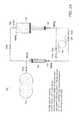
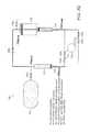
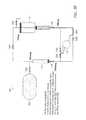
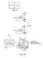
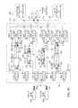
- FIG. 1is a schematic diagram of an open-air hydraulic-pneumatic energy storage and recovery system in accordance with one embodiment of the invention
- FIGS. 1A and 1Bare enlarged schematic views of the accumulator and intensifier components of the system of FIG. 1 ;
- FIGS. 2A-2Qare simplified graphical representations of the system of FIG. 1 illustrating the various operational stages of the system during compression;
- FIGS. 3A-3Mare simplified graphical representations of the system of FIG. 1 illustrating the various operational stages of the system during expansion;
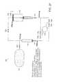
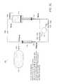
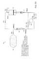
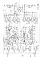
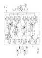
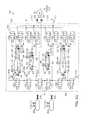
- FIG. 4is a schematic diagram of an open-air hydraulic-pneumatic energy storage and recovery system in accordance with an alternative embodiment of the invention.
- FIGS. 5A-5Nare schematic diagrams of the system of FIG. 4 illustrating the cycling of the various components during an expansion phase of the system;
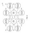
- FIG. 6is a generalized diagram of the various operational states of an open-air hydraulic-pneumatic energy storage and recovery system in accordance with one embodiment of the invention in both an expansion/energy recovery cycle and a compression/energy storage cycle;
- FIGS. 7A-7Fare partial schematic diagrams of an open-air hydraulic-pneumatic energy storage and recovery system in accordance with another alternative embodiment of the invention, illustrating the various operational stages of the system during an expansion phase;
- FIG. 8is a table illustrating the expansion phase for the system of FIGS. 7A-7F ;
- FIG. 9is a schematic diagram of an open-air hydraulic-pneumatic energy storage and recovery system including a heat transfer subsystem in accordance with one embodiment of the invention.
- FIG. 9Ais an enlarged schematic diagram of the heat transfer subsystem portion of the system of FIG. 9 ;
- FIG. 10is a graphical representation of the thermal efficiencies obtained by the system of FIG. 9 at different operating parameters
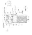
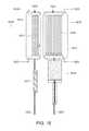
- FIG. 11is a schematic partial cross section of a hydraulic/pneumatic cylinder assembly including a heat transfer subsystem that facilities isothermal expansion within the pneumatic side of the cylinder in accordance with one embodiment of the invention
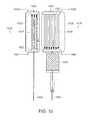
- FIG. 12is a schematic partial cross section of a hydraulic/pneumatic intensifier assembly including a heat transfer subsystem that facilities isothermal expansion within the pneumatic side of the cylinder in accordance with an alternative embodiment of the invention
- FIG. 13is a schematic partial cross section of a hydraulic/pneumatic cylinder assembly having a heat transfer subsystem that facilitates isothermal expansion within the pneumatic side of the cylinder in accordance with another alternative embodiment of the invention in which the cylinder is part of a power generating system;
- FIG. 14Ais a graphical representation of the amount of work produced based upon an adiabatic expansion of gas within the pneumatic side of a cylinder or intensifier for a given pressure versus volume;
- FIG. 14Bis a graphical representation of the amount of work produced based upon an ideal isothermal expansion of gas within the pneumatic side of a cylinder or intensifier for a given pressure versus volume;
- FIG. 14Cis a graphical representation of the amount of work produced based upon a near-isothermal expansion of gas within the pneumatic side of a cylinder or intensifier for a given pressure versus volume;
- FIG. 15is a schematic diagram of a system and method for expedited heat transfer to gas expanding (or being compressed) in an open-air staged hydraulic-pneumatic system in accordance with one embodiment of the invention
- FIG. 16is a schematic diagram of a system and method for expedited heat transfer to gas expanding (or being compressed) in an open-air staged hydraulic-pneumatic system in accordance with another embodiment of the invention
- FIG. 17is a schematic diagram of a system and method for expedited heat transfer to gas expanding (or being compressed) in an open-air staged hydraulic-pneumatic system in accordance with yet another embodiment of the invention.
- FIG. 18is a schematic diagram of a system and method for expedited heat transfer to gas expanding (or being compressed) in an open-air staged hydraulic-pneumatic system in accordance with another embodiment of the invention.
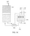
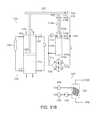
- FIG. 19is a schematic diagram of a system and method for expedited heat transfer to gas expanding (or being compressed) in an open-air staged hydraulic-pneumatic system in accordance with another embodiment of the invention.
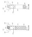
- FIGS. 20A and 20Bare schematic diagrams of a system and method for expedited heat transfer to gas expanding (or being compressed) in an open-air staged hydraulic-pneumatic system in accordance with another embodiment of the invention
- FIGS. 21A-21Care schematic diagrams of a system and method for expedited heat transfer to gas expanding (or being compressed) in an open-air staged hydraulic-pneumatic system in accordance with another embodiment of the invention.
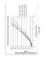
- FIGS. 22A and 22Bare schematic diagrams of a system and method for expedited heat transfer to gas expanding (or being compressed) in an open-air staged hydraulic-pneumatic system in accordance with another embodiment of the invention
- FIG. 22Cis a schematic cross-sectional view of a cylinder assembly for use in the system and method of FIGS. 22A and 22B ;
- FIG. 22Dis a graphical representation of the estimated water spray heat transfer limits for an implementation of the system and method of FIGS. 22A and 22B ;
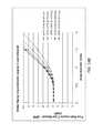
- FIGS. 23A and 23Bare schematic diagrams of a system and method for expedited heat transfer to gas expanding (or being compressed) in an open-air staged hydraulic-pneumatic system in accordance with another embodiment of the invention.
- FIG. 23Cis a schematic cross-sectional view of a cylinder assembly for use in the system and method of FIGS. 23A and 23B ;
- FIG. 23Dis a graphical representation of the estimated water spray heat transfer limits for an implementation of the system and method of FIGS. 23A and 23B ;
- FIGS. 24A and 24Bare graphical representations of the various water spray requirements for the systems and methods of FIGS. 22 and 23 ;
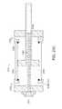
- FIG. 25is a detailed schematic plan view in partial cross-section of a cylinder design for use in any of the foregoing embodiments of the invention described herein for expedited heat transfer to gas expanding (or being compressed) in an open-air staged hydraulic-pneumatic system in accordance with one embodiment of the invention;
- FIG. 26is a detailed schematic plan view in partial cross-section of a cylinder design for use in any of the foregoing embodiments of the invention described herein for expedited heat transfer to gas expanding (or being compressed) in an open-air staged hydraulic-pneumatic system in accordance with one embodiment of the invention;
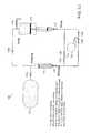
- FIG. 27is a schematic diagram of a compressed-gas storage subsystem for use with systems and methods for heating and cooling compressed gas in energy storage systems in accordance with one embodiment of the invention
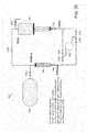
- FIG. 28is a schematic diagram of a compressed-gas storage subsystem for use with systems and methods for heating and cooling of compressed gas for energy storage systems in accordance with an alternative embodiment of the invention
- FIGS. 29A and 29Bare schematic diagrams of a staged hydraulic-pneumatic energy conversion system including a heat transfer subsystem in accordance with one embodiment of the invention.
- FIGS. 30A-30Dare schematic diagrams of a staged hydraulic-pneumatic energy conversion system including a heat transfer subsystem in accordance with an alternative embodiment of the invention.
- FIGS. 31A-31Care schematic diagrams of a staged hydraulic-pneumatic energy conversion system including a heat transfer subsystem in accordance with another alternative embodiment of the invention.
- a two-stage systeme.g., a single accumulator and a single intensifier, an arrangement with two accumulators and two intensifiers and simplified valve arrangements, or one or more pneumatic cylinders coupled with one or more hydraulic cylinders.
- the present inventioncan include any number of stages and combination of cylinders, accumulators, intensifiers, and valve arrangements.
- any dimensional values givenare exemplary only, as the systems according to the invention are scalable and customizable to suit a particular application.
- the terms pneumatic, gas, and airare used interchangeably and the terms hydraulic and liquid are also used interchangeably. Fluid is used to refer to both gas and liquid.
- FIG. 1depicts one embodiment of an open-air hydraulic-pneumatic energy storage and recovery system 100 in accordance with the invention in a neutral state (i.e., all of the valves are closed and energy is neither being stored nor recovered.
- the system 100includes one or more high-pressure gas/air storage tanks 102 a , 102 b , . . . 102 n . Each tank 102 is joined in parallel via a manual valve(s) 104 a , 104 b , . . . 104 n , respectively, to a main air line 108 .
- the valves 104are not limited to manual operation, as the valves can be electrically, hydraulically, or pneumatically actuated, as can all of the valves described herein.
- the tanks 102are each provided with a pressure sensor 112 a , 112 b . . . 112 n and a temperature sensor 114 a , 114 b . . . 114 n .
- These sensors 112 , 114can output electrical signals that can be monitored by a control system 120 via appropriate wired and wireless connections/communications. Additionally, the sensors 112 , 114 could include visual indicators.
- the control system 120can be any acceptable control device with a human-machine interface.
- the control system 120could include a computer (for example a PC-type) that executes a stored control application in the form of a computer-readable software medium.
- the control applicationreceives telemetry from the various sensors to be described below, and provides appropriate feedback to control valve actuators, motors, and other needed electromechanical/electronic devices.
- the system 100further includes pneumatic valves 106 a , 106 b , 106 c , . . . 106 n that control the communication of the main air line 108 with an accumulator 116 and an intensifier 118 .
- the system 100can include any number and combination of accumulators 116 and intensifiers 118 to suit a particular application.
- the pneumatic valves 106are also connected to a vent 110 for exhausting air/gas from the accumulator 116 , the intensifier 118 , and/or the main air line 108 .
- the accumulator 116includes an air chamber 140 and a fluid chamber 138 divided by a movable piston 136 having an appropriate sealing system using sealing rings and other components (not shown) that are known to those of ordinary skill in the art.
- a bladder type, diaphragm type or bellows type barriercould be used to divide the air and fluid chambers 140 , 138 of the accumulator 116 .
- the piston 136moves along the accumulator housing in response to pressure differentials between the air chamber 140 and the opposing fluid chamber 138 .
- hydraulic fluidor another liquid, such as water
- the accumulator 116can also include optional shut-off valves 134 that can be used to isolate the accumulator 116 from the system 100 .
- the valves 134can be manually or automatically operated.
- the intensifier 118includes an air chamber 144 and a fluid chamber 146 divided by a movable piston assembly 142 having an appropriate sealing system using sealing rings and other components that are known to those of ordinary skill in the art. Similar to the accumulator piston 136 , the intensifier piston 142 moves along the intensifier housing in response to pressure differentials between the air chamber 144 and the opposing fluid chamber 146 .
- the intensifier piston assembly 142is actually two pistons: an air piston 142 a connected by a shaft, rod, or other coupling means 143 to a respective fluid piston 142 b .
- the fluid piston 142 bmoves in conjunction with the air piston 142 a , but acts directly upon the associated intensifier fluid chamber 146 .
- the internal diameter (and/or volume) (DAI) of the air chamber for the intensifier 118is greater than the diameter (DAA) of the air chamber for the accumulator 116 .
- the surface of the intensifier piston 142 ais greater than the surface area of the accumulator piston 136 .
- the diameter of the intensifier fluid piston (DFI)is approximately the same as the diameter of the accumulator piston 136 (DFA).
- the ratio of the pressures of the intensifier air chamber 144 and the intensifier fluid chamber 146is greater than the ratio of the pressures of the accumulator air chamber 140 and the accumulator fluid chamber 138 .
- the ratio of the pressures in the accumulatorcould be 1:1, while the ratio of pressures in the intensifier could be 10:1.
- the system 100allows for at least two stages of air pressure to be employed to generate similar levels of fluid pressure.
- a shaded volume in the fluid chamber 146indicates the hydraulic fluid and the intensifier 118 can also include the optional shut-off valves 134 to isolate the intensifier 118 from the system 100 .
- the accumulator 116 and the intensifier 118each include a temperature sensor 122 and a pressure sensor 124 in communication with each air chamber 140 , 144 and each fluid chamber 138 , 146 . These sensors are similar to sensors 112 , 114 and deliver sensor telemetry to the control system 120 , which in turn can send signals to control the valve arrangements.
- the pistons 136 , 142can include position sensors 148 that report the present position of the pistons 136 , 142 to the control system 120 . The position and/or rate of movement of the pistons 136 , 142 can be used to determine relative pressure and flow of both the gas and the fluid.
- the system 100further includes hydraulic valves 128 a , 128 b , 128 c , 128 d . . . 128 n that control the communication of the fluid connections of the accumulator 116 and the intensifier 118 with a hydraulic motor 130 .
- the specific number, type, and arrangement of the hydraulic valves 128 and the pneumatic valves 106are collectively referred to as the control valve arrangements.
- the valvesare generally depicted as simple two way valves (i.e., shut-off valves); however, the valves could essentially be any configuration as needed to control the flow of air and/or fluid in a particular manner.
- the hydraulic line between the accumulator 116 and valves 128 a , 128 b and the hydraulic line between the intensifier 118 and valves 128 c , 128 dcan include flow sensors 126 that relay information to the control system 120 .
- the motor/pump 130can be a piston-type assembly having a shaft 131 (or other mechanical coupling) that drives, and is driven by, a combination electrical motor and generator assembly 132 .
- the motor/pump 130could also be, for example, an impeller, vane, or gear type assembly.
- the motor/generator assembly 132is interconnected with a power distribution system and can be monitored for status and output/input level by the control system 120 .
- One advantage of the system depicted in FIG. 1is that it achieves approximately double the power output in, for example, a 3000-300 psig range without additional components. Shuffling the hydraulic fluid back and forth between the intensifier 118 and the accumulator 116 allows for the same power output as a system with twice the number of intensifiers and accumulators while expanding or compressing in the 250-3000 psig pressure range. In addition, this system arrangement can eliminate potential issues with self-priming for certain the hydraulic motors/pumps when in the pumping mode (i.e., compression phase).
- FIGS. 2A-2Qrepresent, in a simplified graphical manner, the various operational stages of the system 100 during a compression phase, where the storage tanks 102 are charged with high pressure air/gas (i.e., energy is stored).
- high pressure air/gasi.e., energy is stored.
- only one storage tank 102is shown and some of the valves and sensors are omitted for clarity.
- the pressures shownare for reference only and will vary depending on the specific operating parameters of the system 100 .
- the system 100is in a neutral state, where the pneumatic valves 106 and the hydraulic valves 128 are closed. Shut-off valves 134 are open in every operational stage to maintain the accumulator 116 and intensifier 118 in communication with the system 100 .
- the accumulator fluid chamber 138is substantially filled, while the intensifier fluid chamber is substantially empty.
- the storage tank 102is typically at a low pressure (approximately 0 psig) prior to charging and the hydraulic motor/pump 130 is stationary.
- pneumatic valve 106 bis open, thereby allowing fluid communication between the accumulator air chamber 140 and the intensifier air chamber 144
- hydraulic valves 128 a , 128 dare open, thereby allowing fluid communication between the accumulator fluid chamber 138 and the intensifier fluid chamber 146 via the hydraulic motor/pump 130 .
- the motor/generator 132(see FIG. 1 ) begins to drive the motor/pump 130
- the air pressure between the intensifier 118 and the accumulator 116begins to increase, as fluid is driven to the intensifier fluid chamber 144 under pressure.
- the pressure or mechanical energyis transferred to the air chamber 146 via the piston 142 .
- This increase of air pressure in the accumulator air chamber 140pressurizes the fluid chamber 138 of the accumulator 116 , thereby providing pressurized fluid to the motor/pump 130 inlet, which can eliminate self-priming concerns.
- FIGS. 2D , 2 E, and 2 Fthe motor/generator 132 continues to drive the motor/pump 130 , thereby transferring the hydraulic fluid from the accumulator 116 to the intensifier 118 , which in turn continues to pressurize the air between the accumulator and intensifier air chamber 140 , 146 .
- FIG. 2Fdepicts the completion of the first stage of the compression phase.
- the pneumatic and hydraulic valves 106 , 128are all closed.
- the fluid chamber 144 of the intensifier 118is substantially filled with fluid at a high pressure (for example, about 3000 psig) and the accumulator fluid chamber 138 is substantially empty and maintained at a mid-range pressure (for example, about 250 psig).
- the pressures in the accumulator and intensifier air chambers 140 , 146are maintained at the mid-range pressure.
- FIG. 2GThe beginning of the second stage of the compression phase is shown in FIG. 2G , where hydraulic valves 128 b , 128 c are open and the pneumatic valves 106 are all closed, thereby putting the intensifier fluid chamber 144 at high pressure in communication with the motor/pump 130 .
- the pressure of any gas remaining in the intensifier air chamber 146will assist in driving the motor/pump 130 .
- the motor/generatorwill draw electricity to drive the motor/pump 130 and further pressurize the accumulator fluid chamber 138 .
- the motor/pump 130continues to pressurize the accumulator fluid chamber 138 , which in turn pressurizes the accumulator air chamber 140 .
- the intensifier fluid chamber 146is at a low pressure and the intensifier air chamber 144 is at substantially atmospheric pressure. Once the intensifier air chamber 144 reaches substantially atmospheric pressure, pneumatic vent valve 106 c is opened.
- the weight of the intensifier piston 142can provide the necessary back-pressure to the motor/pump 130 , which would overcome potential self-priming issues for certain motors/pumps.
- FIG. 2Kalso depicts the change-over in the control valve arrangement when the accumulator air chamber 140 reaches the predetermined high pressure for the system 100 .
- Pneumatic valve 106 ais opened to allow the high pressure gas to enter the storage tanks 102 .
- FIG. 2Ldepicts the end of the second stage of one compression cycle, where all of the hydraulic and the pneumatic valves 128 , 106 are closed.
- the system 100will now begin another compression cycle, where the system 100 shuttles the hydraulic fluid back to the intensifier 118 from the accumulator 116 .
- FIG. 2Mdepicts the beginning of the next compression cycle.
- the pneumatic valves 106are closed and hydraulic valves 128 a , 128 d are open.
- the residual pressure of any gas remaining in the accumulator fluid chamber 138drives the motor/pump 130 initially, thereby eliminating the need to draw electricity.
- FIG. 2Nand described with respect to FIG. 2G , once the hydraulic pressure equalizes between the accumulator and intensifier fluid chambers 138 , 144 the motor/generator 132 will draw electricity to drive the motor/pump 130 and further pressurize the intensifier fluid chamber 144 .
- the accumulator air chamber 140 pressuredecreases and the intensifier air chamber 146 pressure increases.
- the system 100continues the process as shown and described in FIGS. 2G-2K to continue storing high pressure air in the storage tanks 102 .
- the system 100will perform as many compression cycles (i.e., the shuttling of hydraulic fluid between the accumulator 116 and the intensifier 118 ) as necessary to reach a desired pressure of the air in the storage tanks 102 (i.e., a full compression phase).
- FIGS. 3A-3Mrepresent, in a simplified graphical manner, the various operational stages of the system 100 during an expansion phase, where energy (i.e., the stored compressed gas) is recovered.
- FIGS. 3A-3Muse the same designations, symbols, and exemplary numbers as shown in FIGS. 2A-2Q . It should be noted that while the system 100 is described as being used to compress the air in the storage tanks 102 , alternatively, the tanks 102 could be charged (for example, an initial charge) by a separate compressor unit.
- the system 100is in a neutral state, where the pneumatic valves 106 and the hydraulic valves 128 are all closed.
- the shut-off valves 134are open to maintain the accumulator 116 and intensifier 118 in communication with the system 100 .
- the accumulator fluid chamber 138is substantially filled, while the intensifier fluid chamber 146 is substantially empty.
- the storage tank 102is at a high pressure (for example, 3000 psig) and the hydraulic motor/pump 130 is stationary.
- FIG. 3Bdepicts a first stage of the expansion phase, where pneumatic valves 106 a , 106 c are open.
- Open pneumatic valve 106 aconnects the high pressure storage tanks 102 in fluid communication with the accumulator air chamber 140 , which in turn pressurizes the accumulator fluid chamber 138 .
- Open pneumatic valve 106 cvents the intensifier air chamber 146 to atmosphere.
- Hydraulic valves 128 a , 128 dare open to allow fluid to flow from the accumulator fluid chamber 138 to drive the motor/pump 130 , which in turn drives the motor/generator 132 , thereby generating electricity.
- the generated electricitycan be delivered directly to a power grid or stored for later use, for example, during peak usage times.
- pneumatic valve 106 ais closed to isolate the storage tanks 102 from the accumulator air chamber 140 .
- the high pressure in the accumulator air chamber 140continues to drive the hydraulic fluid from the accumulator fluid chamber 138 through the motor/pump 130 and to the intensifier fluid chamber 146 , thereby continuing to drive the motor/generator 132 and generate electricity.
- the pressure in the accumulator air chamber 140decreases and the air in the intensifier air chamber 144 is vented through pneumatic valve 106 C.
- FIG. 3Gdepicts the end of the first stage of the expansion phase.
- a second predetermined mid-pressurefor example, about 300 psig
- all of the hydraulic and pneumatic valves 128 , 106are closed.
- the pressure in the accumulator fluid chamber 138 , the intensifier fluid chamber 146 , and the intensifier air chamber 144are at approximately atmospheric pressure.
- the pressure in the accumulator air chamber 140is maintained at the predetermined mid-pressure.
- FIG. 3Hdepicts the beginning of the second stage of the expansion phase.
- Pneumatic valve 106 bis opened to allow fluid communication between the accumulator air chamber 140 and the intensifier air chamber 144 .
- the predetermined pressurewill decrease slightly when the valve 106 b is opened and the accumulator air chamber 140 and the intensifier air chamber 144 are connected.
- Hydraulic valves 128 b , 128 dare opened, thereby allowing the hydraulic fluid stored in the intensifier to transfer to the accumulator fluid chamber 138 through the motor/pump 130 , which in turn drives the motor/generator 132 and generates electricity.
- the air transferred from the accumulator air chamber 140 to the intensifier air chamber 144 to drive the fluid from the intensifier fluid chamber 146 to the accumulator fluid chamber 138is at a lower pressure than the air that drove the fluid from the accumulator fluid chamber 138 to the intensifier fluid chamber 146 .
- the area differential between the air piston 142 a and the fluid piston 142 b(for example, 10:1) allows the lower pressure air to transfer the fluid from the intensifier fluid chamber 146 at a high pressure.
- the pressure in the intensifier air chamber 144continues to drive the hydraulic fluid from the intensifier fluid chamber 146 through the motor/pump 130 and to the accumulator fluid chamber 138 , thereby continuing to drive the motor/generator 132 and generate electricity.
- the pressures in the intensifier air chamber 144 , the intensifier fluid chamber 146 , the accumulator air chamber 140 , and the accumulator fluid chamber 138decrease.
- FIG. 3Ldepicts the end of the second stage of the expansion cycle, where substantially all of the hydraulic fluid has been transferred to the accumulator 116 and all of the valves 106 , 128 are closed.
- the accumulator air chamber 140 , the accumulator fluid chamber 138 , the intensifier air chamber 144 , and the intensifier fluid chamber 146are all at low pressure.
- the hydraulic fluidcan be shuffled back and forth between two intensifiers for compressing and expanding in the low pressure (for example, about 0-250 psig) range.
- Using a second intensifier and appropriate valving to utilize the energy stored at the lower pressurescan produce additional electricity.
- Using a second intensifier and appropriate valving to utilize the energy stored at the lower pressurescan allow for a greater depth of discharge from the gas storage tanks, storing and recovering additional energy for a given storage volume.
- FIG. 3Mdepicts the start of another expansion phase, as described with respect to FIG. 3B .
- the system 100can continue to cycle through expansion phases as necessary for the production of electricity, or until all of the compressed air in the storage tanks 102 has been exhausted.
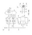
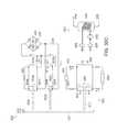
- FIG. 4is a schematic diagram of an energy storage system 300 , employing open-air hydraulic-pneumatic principles according to one embodiment of this invention.
- the system 300consists of one or more high-pressure gas/air storage tanks 302 a , 302 b , . . . 302 n (the number being highly variable to suit a particular application).
- Each tank 302 a , 302 bis joined in parallel via a manual valve(s) 304 a , 304 b , . . . 304 n respectively to a main air line 308 .
- the tanks 302 a , 302 bare each provided with a pressure sensor 312 a , 312 b . . .
- controller 350can be any acceptable control device with a human-machine interface.
- the controller 350includes a computer 351 (for example a PC-type) that executes a stored control application 353 in the form of a computer-readable software medium.
- the control application 353receives telemetry from the various sensors and provides appropriate feedback to control valve actuators, motors, and other needed electromechanical/electronic devices.
- An appropriate interfacecan be used to convert data from sensors into a form readable by the computer controller 351 (such as RS-232 or network-based interconnects). Likewise, the interface converts the computer's control signals into a form usable by valves and other actuators to perform an operation. The provision of such interfaces should be clear to those of ordinary skill in the art.
- the main air line 308 from the tanks 302 a , 302 bis coupled to a pair of multi-stage (two stages in this example) accumulator/intensifier circuits (or hydraulic-pneumatic cylinder circuits) (dashed boxes 360 , 362 ) via automatically controlled (via controller 350 ), two-position valves 307 a , 307 b , 307 c and 306 a , 306 b and 306 c . These valves are coupled to respective accumulators 316 and 317 and intensifiers 318 and 319 according to one embodiment of the system. Pneumatic valves 306 a and 307 a are also coupled to a respective atmospheric air vent 310 b and 310 a .
- valves 306 c and 307 cconnect along a common air line 390 , 391 between the main air line 308 and the accumulators 316 and 317 , respectively.
- Pneumatic valves 306 b and 307 bconnect between the respective accumulators 316 and 317 , and intensifiers 318 and 319 .
- Pneumatic valves 306 a , 307 aconnect along the common lines 390 , 391 between the intensifiers 318 and 319 , and the atmospheric vents 310 b and 310 a.
- the air from the tanks 302selectively communicates with the air chamber side of each accumulator and intensifier (referenced in the drawings as air chamber 340 for accumulator 316 , air chamber 341 for accumulator 317 , air chamber 344 for intensifier 318 , and air chamber 345 for intensifier 319 ).
- An air temperature sensor 322 and a pressure sensor 324communicate with each air chamber 341 , 344 , 345 , 322 , and deliver sensor telemetry to the controller 350 .
- each accumulator 316 , 317is enclosed by a movable piston 336 , 337 having an appropriate sealing system using sealing rings and other components that are known to those of ordinary skill in the art.
- the piston 336 , 337moves along the accumulator housing in response to pressure differentials between the air chamber 340 , 341 and an opposing fluid chamber 338 , 339 , respectively, on the opposite side of the accumulator housing.
- hydraulic fluidor another liquid, such as water
- the air chambers 344 , 345 of the respective intensifiers 318 , 319are enclosed by a moving piston assembly 342 , 343 .
- the intensifier air piston 342 a , 343 ais connected by a shaft, rod, or other coupling to a respective fluid piston, 342 b , 343 b .
- This fluid piston 342 b , 343 bmoves in conjunction with the air piston 342 a , 343 a , but acts directly upon the associated intensifier fluid chamber 346 , 347 .
- the internal diameter (and/or volume) of the air chamber (DAI) for the intensifier 318 , 319is greater than the diameter of the air chamber (DAA) for the accumulator 316 , 317 in the same circuit 360 , 362 .
- each intensifier fluid pistonis approximately the same as the diameter of each accumulator (DFA).
- the area of the gas piston in the intensifierwould be approximately 10 times the area of the piston in the accumulator (or 3.16 times the radius).
- ATMatmospheres
- mid-pressurethe precise values for initial high-pressure, mid-pressure and final low-pressure are highly variable, depending in part upon the operating specifications of the system components, scale of the system and output requirements.
- the relative sizing of the accumulators and the intensifiersis variable to suit a particular application.
- Each fluid chamber 338 , 339 , 346 , 347is interconnected with an appropriate temperature sensor 322 and pressure sensor 324 , each delivering telemetry to the controller 350 .
- each fluid line interconnecting the fluid chamberscan be fitted with a flow sensor 326 , which directs data to the controller 350 .
- the pistons 336 , 337 , 342 and 343can include position sensors 348 that report their present position to the controller 350 . The position of the piston can be used to determine relative pressure and flow of both gas and fluid.
- Each fluid connection from a fluid chamber 338 , 339 , 346 , 347is connected to a pair of parallel, automatically controlled valves.
- fluid chamber 338(accumulator 316 ) is connected to valve pair 328 c and 328 d ; fluid chamber 339 (accumulator 317 ) is connected to valve pair 329 a and 329 b ; fluid chamber 346 (intensifier 318 ) is connected to valve pair 328 a and 328 b ; and fluid chamber 347 (intensifier 319 ) is connected to valve pair 329 c and 329 d .
- One valve from each chamber 328 b , 328 d , 329 a and 329 cis connected to one connection side 372 of a hydraulic motor/pump 330 .
- This motor/pump 330can be piston-type (or other suitable type, including vane, impeller, and gear) assembly having a shaft 331 (or other mechanical coupling) that drives, and is driven by, a combination electrical motor/generator assembly 332 .
- the motor/generator assembly 332is interconnected with a power distribution system and can be monitored for status and output/input level by the controller 350 .
- the other connection side 374 of the hydraulic motor/pump 330is connected to the second valve in each valve pair 328 a , 328 c , 329 b and 329 d . By selectively toggling the valves in each pair, fluid is connected between either side 372 , 374 of the hydraulic motor/pump 330 .
- some or all of the valve pairscan be replaced with one or more three position, four way valves or other combinations of valves to suit a particular application.
- the number of circuits 360 , 362can be increased as necessary. Additional circuits can be interconnected to the tanks 302 and each side 372 , 374 of the hydraulic motor/pump 330 in the same manner as the components of the circuits 360 , 362 . Generally, the number of circuits should be even so that one circuit acts as a fluid driver while the other circuit acts as a reservoir for receiving the fluid from the driving circuit.
- An optional accumulator 366is connected to at least one side (e.g., inlet side 372 ) of the hydraulic motor/pump 330 .
- the optional accumulator 366can be, for example, a closed-air-type accumulator with a separate fluid side 368 and precharged air side 370 .
- the accumulator 366acts as a fluid capacitor to deal with transients in fluid flow through the motor/pump 330 .
- a second optional accumulator or other low-pressure reservoir 371is placed in fluid communication with the outlet side 374 of the motor/pump 330 and can also include a fluid side 371 and a precharged air side 369 .
- the foregoing optional accumulatorscan be used with any of the systems described herein.
- FIGS. 5A-5NFor the purposes of this operational description, the illustrations of the system 300 in FIGS. 5A-5N have been simplified, omitting the controller 350 and interconnections with valves, sensors, etc. It should be understood, that the steps described are under the control and monitoring of the controller 350 based upon the rules established by the application 353 .
- FIG. 5Ais a schematic diagram of the energy storage and recovery system of FIG. 4 showing an initial physical state of the system 300 in which an accumulator 316 of a first circuit is filled with high-pressure gas from the high-pressure gas storage tanks 302 .
- the tanks 302have been filled to full pressure, either by the cycle of the system 300 under power input to the hydraulic motor/pump 330 , or by a separate high-pressure air pump 376 .
- This air pump 376is optional, as the air tanks 302 can be filled by running the recovery cycle in reverse.
- the tanks 302 in this embodimentcan be filled to a pressure of 200 ATM (3000 psi) or more.
- the overall, collective volume of the tanks 302is highly variable and depends in part upon the amount of energy to be stored.
- valve 307 cis opened allowing a flow of high-pressure air to pass into the air chamber 340 of the accumulator 316 .
- the level of pressureis reported by the sensor 324 in communication with the chamber 340 .
- the pressureis maintained at the desired level by valve 307 c .
- This pressurecauses the piston 336 to bias (arrow 800 ) toward the fluid chamber 338 , thereby generating a comparable pressure in the incompressible fluid.
- the fluidis prevented from moving out of the fluid chamber 338 at this time by valves 329 c and 329 d ).
- FIG. 5Bis a schematic diagram of the energy storage and recovery system of FIG. 4 showing a physical state of the system 300 following the state of FIG. 5A , in which valves are opened to allow fluid to flow from the accumulator 316 of the first circuit to the fluid motor/pump 330 to generate electricity therefrom.
- pneumatic valve 307 cremains open.
- the fluid valve 329 cis opened by the controller, causing a flow of fluid (arrow 801 ) to the inlet side 372 of the hydraulic motor/pump 330 (which operates in motor mode during the recovery phase).
- the motion of the motor 330drives the electric motor/generator 332 in a generation mode, providing power to the facility or grid as shown by the term “POWER OUT.”
- fluid valve 328 cis opened to the fluid chamber 339 by the controller 350 to route fluid to the opposing accumulator 317 .
- the air chamber 341is vented by opening pneumatic vent valves 306 a , 306 b . This allows any air in the chamber 341 , to escape to the atmosphere via the vent 310 b as the piston 337 moves (arrow 805 ) in response to the entry of fluid.
- FIG. 5Cis a schematic diagram of the energy storage and recovery system of FIG. 4 showing a physical state of the system 300 following the state of FIG. 5B , in which the accumulator 316 of the first circuit directs fluid to the fluid motor/pump 330 while the accumulator 317 of the second circuit receives exhausted fluid from the motor/pump 330 , as gas in its air chamber 341 is vented to atmosphere.
- a predetermined amount of gashas been allowed to flow from the high-pressure tanks 302 to the accumulator 316 and the controller 350 now closes pneumatic valve 307 c .
- Other valvesremain open so that fluid can continue to be driven by the accumulator 316 through the motor/pump 330 .
- FIG. 5Dis a schematic diagram of the energy storage and recovery system of FIG. 4 showing a physical state of the system 300 following the state of FIG. 5C , in which the accumulator 316 of the first circuit continues to direct fluid to the fluid motor/pump 330 while the accumulator 317 of the second circuit continues to receive exhausted fluid from the motor/pump 330 , as gas in its air chamber 341 is vented to atmosphere.
- the operationcontinues, where the accumulator piston 136 drives additional fluid (arrow 800 ) through the motor/pump 330 based upon the charge of gas pressure placed in the accumulator air chamber 340 by the tanks 302 .
- the fluidcauses the opposing accumulator's piston 337 to move (arrow 805 ), displacing air through the vent 310 b.
- FIG. 5Eis a schematic diagram of the energy storage and recovery system of FIG. 4 showing a physical state of the system 300 following the state of FIG. 5D , in which the accumulator 316 of the first circuit has nearly exhausted the fluid in its fluid chamber 338 and the gas in its air chamber 340 has expanded to nearly mid-pressure from high-pressure.
- the charge of gas in the air chamber 340 of the accumulator 316has continued to drive fluid (arrows 800 , 801 ) through the motor/pump 330 while displacing air via the air vent 310 b .
- the gashas expanded from high-pressure to mid-pressure during this portion of the energy recovery cycle. Consequently, the fluid has ranged from high to mid-pressure.
- the rate of expansioncan be controlled.
- heat transfercan occur through the walls of the accumulators and/or intensifiers, or heat-transfer mechanisms can act upon the expanding or compressing gas to absorb or radiate heat from or to an environmental or other source. The rate of this heat transfer is governed by the thermal properties and characteristics of the accumulators/intensifiers, which can be used to determine a thermal time constant.
- the accumulatorscan be submerged in a water bath or water/fluid flow can be circulated around the accumulators and intensifiers.
- the accumulatorscan alternatively be surrounded with heating/cooling coils or a flow of warm air can be blown past the accumulators/intensifiers.
- any technique that allows for mass flow transfer of heat to and from the accumulatorscan be employed.
- FIG. 5Fis a schematic diagram of the energy storage and recovery system of FIG. 4 , showing a physical state of the system 300 following the state of FIG. 5E in which the accumulator 316 of the first circuit has exhausted the fluid in its fluid chamber 338 and the gas in its air chamber 340 has expanded to mid-pressure from high-pressure, and the valves have been momentarily closed on both the first circuit and the second circuit, while the optional accumulator 366 delivers fluid through the motor/pump 330 to maintain operation of the electric motor/generator 332 between cycles.
- the piston 336 of the accumulator 316has driven all fluid out of the fluid chamber 338 as the gas in the air chamber 340 has fully expanded (to mid-pressure of 20 ATM, per the example).
- Fluid valves 329 c and 328 care closed by the controller 350 .
- the opening and closing of valvesis carefully timed so that a flow through the motor/pump 330 is maintained.
- brief interruptions in fluid pressurecan be accommodated by pressurized fluid flow 710 from the optional accumulator ( 366 in FIG. 4 ), which is directed through the motor/pump 330 to the second optional accumulator ( 367 in FIG. 4 ) at low-pressure as an exhaust fluid flow 720 .
- the exhaust flowcan be directed to a simple low-pressure reservoir that is used to refill the first accumulator 366 .
- the exhaust flowcan be directed to the second optional accumulator ( 367 in FIG.
- FIG. 5Gis a schematic diagram of the energy storage and recovery system of FIG. 4 showing a physical state of the system 300 following the state of FIG. 5F , in which pneumatic valves 307 b , 306 a are opened to allow mid-pressure gas from the air chamber 340 of the first circuit's accumulator 316 to flow into the air chamber 344 of the first circuit's intensifier 318 , while fluid from the first circuit's intensifier 318 is directed through the motor/pump 330 and exhausted fluid fills the fluid chamber 347 of second circuit's intensifier 319 , whose air chamber 345 is vented to atmosphere.
- pneumatic valve 307 bis opened, while the tank outlet valve 307 c remains closed.
- the volume of the air chamber 340 of accumulator 316is coupled to the air chamber 344 of the intensifier 318 .
- the accumulator's air pressurehas been reduced to a mid-pressure level, well below the initial charge from the tanks 302 .
- the airthus, flows (arrow 810 ) through valve 307 b to the air chamber 344 of the intensifier 318 .
- Thisdrives the air piston 342 a (arrow 830 ). Since the area of the air-contacting piston 342 a is larger than that of the piston 336 in the accumulator 316 , the lower air pressure still generates a substantially equivalent higher fluid pressure on the smaller-area, coupled fluid piston 342 b of the intensifier 318 .
- the fluid in the fluid chamber 346thereby flows under pressure through opened fluid valve 329 a (arrow 840 ) and into the inlet side 372 of the motor/pump 330 .
- the outlet fluid from the motor pump 330is directed (arrow 850 ) through now-opened fluid valve 328 a to the opposing intensifier 319 .
- the fluidenters the fluid chamber 347 of the intensifier 319 , biasing (arrow 860 ) the fluid piston 343 b (and interconnected gas piston 343 a ). Any gas in the air chamber 345 of the intensifier 319 is vented through the now opened vent valve 306 a to atmosphere via the vent 310 b .
- the mid-level gas pressure in the accumulator 316is directed (arrow 820 ) to the intensifier 318 , the piston 342 a of which drives fluid from the chamber 346 using the coupled, smaller-diameter fluid piston 342 b .
- This portion of the recovery stagemaintains a reasonably high fluid pressure, despite lower gas pressure, thereby ensuring that the motor/pump 330 continues to operate within a predetermined range of fluid pressures, which is desirable to maintain optimal operating efficiencies for the given motor.
- the multi-stage circuits of this embodimenteffectively restrict the operating pressure range of the hydraulic fluid delivered to the motor/pump 330 above a predetermined level despite the wide range of pressures within the expanding gas charge provided by the high-pressure tank.
- FIG. 5His a schematic diagram of the energy storage and recovery system of FIG. 4 showing a physical state of the system following the state of FIG. 5G , in which the intensifier 318 of the first circuit directs fluid to the fluid motor/pump 330 based upon mid-pressure gas from the first circuit's accumulator 316 while the intensifier 319 of the second circuit receives exhausted fluid from the motor/pump 330 , as gas in its air chamber 345 is vented to atmosphere. As shown in FIG. 5H , the gas in intensifier 318 continues to expand from mid-pressure to low-pressure. Conversely, the size differential between coupled air and fluid pistons 342 a and 342 b , respectively, causes the fluid pressure to vary between high and mid-pressure. In this manner, motor/pump operating efficiency is maintained.
- FIG. 5Iis a schematic diagram of the energy storage and recovery system of FIG. 4 showing a physical state of the system following the state of FIG. 5H , in which the intensifier 318 of the first circuit has almost exhausted the fluid in its fluid chamber 346 and the gas in its air chamber 344 , delivered from the first circuit's accumulator 316 , has expanded to nearly low-pressure from the mid-pressure. As discussed with respect to FIG. 5H , the gas in intensifier 318 continues to expand from mid-pressure to low-pressure. Again, the size differential between coupled air and fluid pistons 342 a and 342 b , respectively, causes the fluid pressure to vary between high and mid-pressure to maintain motor/pump operating efficiency.
- FIG. 5Jis a schematic diagram of the energy storage and recovery system of FIG. 4 showing a physical state of the system 300 following the state of FIG. 5I , in which the intensifier 318 of the first circuit has essentially exhausted the fluid in its fluid chamber 346 and the gas in its air chamber 344 , delivered from the first circuit's accumulator 316 , has expanded to low-pressure from the mid-pressure.
- the intensifier's piston 342reaches full stroke, while the fluid is driven fully from high to mid-pressure in the fluid chamber 346 .
- the opposing intensifier's fluid chamber 347has filled with fluid from the outlet side 374 of the motor/pump 330 .
- FIG. 5Kis a schematic diagram of the energy storage and recovery system of FIG. 4 showing a physical state of the system following the state of FIG. 5J , in which the intensifier 318 of the first circuit has exhausted the fluid in its fluid chamber 346 and the gas in its air chamber 344 has expanded to low-pressure, and the valves have been momentarily closed on both the first circuit and the second circuit in preparation of switching-over to an expansion cycle in the second circuit, whose accumulator and intensifier fluid chambers 339 , 347 are now filled with fluid.
- the optional accumulator 366can deliver fluid through the motor/pump 330 to maintain operation of the motor/generator 332 between cycles. As shown in FIG.
- pneumatic valve 307 blocated between the accumulator 316 and the intensifier 318 of the circuit 362 , is closed.
- the gas charge initiated in FIG. 5Ahas been fully expanded through two stages with relatively gradual, isothermal expansion characteristics, while the motor/pump 330 has received fluid flow within a desirable operating pressure range.
- the fluid valves 329 a and 328 aare momentarily closed.
- the above-described optional accumulator 366 , and/or other interconnected pneumatic/hydraulic accumulator/intensifier circuitscan maintain predetermined fluid flow through the motor/pump 330 while the valves of the subject circuits 360 , 362 are momentarily closed.
- the optional accumulators and reservoirs 366 , 367as shown in FIG. 4 , can provide a continuing flow 710 of pressurized fluid through the motor/pump 330 , and into the reservoir or low-pressure accumulator (exhaust fluid flow 720 ). The full range of pressure in the previous gas charge being utilized by the system 300 .
- FIG. 5Lis a schematic diagram of the energy storage and recovery system of FIG. 4 showing a physical state of the system following the state of FIG. 5K , in which the accumulator 317 of the second circuit is filled with high-pressure gas from the high-pressure tanks 302 as part of the switch-over to the second circuit as an expansion circuit, while the first circuit receives exhausted fluid and is vented to atmosphere while the optional accumulator 366 delivers fluid through the motor/pump 330 to maintain operation of the motor/generator between cycles. As shown in FIG. 5L , the cycle continues with a new charge of high-pressure (slightly lower) gas from the tanks 302 delivered to the opposing accumulator 317 .
- pneumatic valve 306 cis now opened by the controller 350 , allowing a charge of relatively high-pressure gas to flow (arrow 815 ) into the air chamber 341 of the accumulator 317 , which builds a corresponding high-pressure charge in the air chamber 341 .
- FIG. 5Mis a schematic diagram of the energy storage and recovery system of FIG. 4 showing a physical state of the system following the state of FIG. 5L , in which valves are opened to allow fluid to flow from the accumulator 317 of the second circuit to the fluid motor/pump 330 to generate electricity therefrom, while the first circuit's accumulator 316 , whose air chamber 340 is vented to atmosphere, receives exhausted fluid from the motor/pump 330 . As shown in FIG.
- the pneumatic valve 306 cis closed and the fluid valves 328 d and 329 d are opened on the fluid side of the circuits 360 , 362 , thereby allowing the accumulator piston 337 to move (arrow 816 ) under pressure of the charged air chamber 341 .
- Thisdirects fluid under high pressure through the inlet side 372 of the motor/pump 330 (arrow 817 ), and then through the outlet 374 .
- the exhausted fluidis directed (arrow 818 ) now to the fluid chamber 338 of accumulator 316 .
- Pneumatic valves 307 a and 307 bhave been opened, allowing the low-pressure air in the air chamber 340 of the accumulator 316 to vent (arrow 819 ) to atmosphere via vent 310 a .
- the piston 336 of the accumulator 316can move (arrow 821 ) without resistance to accommodate the fluid from the motor/pump outlet 374 .
- FIG. 5Nis a schematic diagram of the energy storage and recovery system of FIG. 4 showing a physical state of the system following the state of FIG. 5M , in which the accumulator 317 of the second circuit 362 continues to direct fluid to the fluid motor/pump 330 while the accumulator 316 of the first circuit continues to receive exhausted fluid from the motor/pump 330 , as gas in its air chamber 340 is vented to atmosphere, the cycle eventually directing mid-pressure air to the second circuit's intensifier 319 to drain the fluid therein. As shown in FIG. 5N , the high-pressure gas charge in the accumulator 317 expands more fully within the air chamber 341 (arrow 816 ). Eventually, the charge in the air chamber 341 is fully expanded.
- the mid-pressure charge in the air chamber 341is then coupled via open pneumatic valve 306 b to the intensifier 319 , which fills the opposing intensifier 318 with spent fluid from the outlet 374 .
- the processrepeats until a given amount of energy is recovered or the pressure in the tanks 302 drops below a predetermined level.
- the system 300could be run in reverse to compress gas in the tanks 302 by powering the electric generator/motor 332 to drive the motor/pump 330 in pump mode.
- the above-described processoccurs in reverse order, with driven fluid causing compression within both stages of the air system in turn. That is, air is first compressed to a mid-pressure after being drawn into the intensifier from the environment. This mid-pressure air is then directed to the air chamber of the accumulator, where fluid then forces it to be compressed to high pressure. The high-pressure air is then forced into the tanks 302 .
- This compression/energy storage stage and the above-described expansion/energy recovery stagesare discussed with reference to the general system state diagram shown in FIG. 6 .
- the compression and expansion cycleis predicated upon the presence of gas in the storage tanks 302 that is currently at a pressure above the mid-pressure level (e.g., above 20 ATM).
- the valvescan be configured by the controller to employ only the intensifier for compression and expansion. That is, lower gas pressures are accommodated using the larger-area gas pistons on the intensifiers, while higher pressures employ the smaller-area gas pistons of the accumulators, 316 , 317 .
- high-pressure storage tankscan be implemented using standard steel or composite cylindrical pressure vessels (e.g. Compressed Natural Gas 5500-psi steel cylinders).
- the accumulatorscan be implemented using standard steel or composite pressure cylinders with moveable pistons (e.g., a four-inch-inner-diameter piston accumulator).
- Intensifiershaving characteristics similar to the exemplary accumulator can be implemented (e.g., a fourteen-inch booster diameter and four-inch bore diameter single-acting pressure booster available from Parker-Hannifin of Cleveland, Ohio).
- a fluid motor/pumpcan be a standard high-efficiency axial piston, radial piston, or gear-based hydraulic motor/pump, and the associated electrical generator is also available commercially from a variety of industrial suppliers. Valves, lines, and fittings are commercially available with the specified characteristics as well.
- FIG. 6details a generalized state diagram 600 that can be employed by the control application 353 to operate the system's valves and motor/generator based upon the direction of the energy cycle (recovery/expansion or storage/compression) based upon the reported states of the various pressure, temperature, piston-position, and/or flow sensors.
- Base State 1( 610 ) is a state of the system in which all valves are closed and the system is neither compressing nor expanding gas.
- a first accumulator and intensifier(e.g., 316 , 318 ) are filled with the maximum volume of hydraulic fluid and second accumulator and intensifier 1 (e.g., 317 , 319 ) are filled with the maximum volume of air, which may or may not be at a pressure greater than atmospheric.
- the physical system state corresponding to Base State 1is shown in FIG. 5A .
- Base State 2 ( 620 ) of FIG. 6is a state of the system in which all valves are closed and the system is neither compressing nor expanding gas.
- the second accumulator and intensifierare filled with the maximum volume of hydraulic fluid and the first accumulator and intensifier are filled with the maximum volume of air, which may or may not be at a pressure greater than atmospheric.
- the physical system state corresponding to Base State 2is shown in FIG. 5K .
- Base State 1 and Base State 2each link to a state termed Single Stage Compression 630 .
- This general staterepresents a series of states of the system in which gas is compressed to store energy, and which occurs when the pressure in the storage tanks 302 is less than the mid-pressure level. Gas is admitted (from the environment, for example) into the intensifier ( 318 or 319 -depending upon the current base state), and is then pressurized by driving hydraulic fluid into that intensifier. When the pressure of the gas in the intensifier reaches the pressure in the storage tanks 302 , the gas is admitted into the storage tanks 302 . This process repeats for the other intensifier, and the system returns to the original base state ( 610 or 620 ).
- the Two Stage Compression 632 shown in FIG. 6represents a series of states of the system in which gas is compressed in two stages to store energy, and which occurs when the pressure in the storage tanks 302 is greater than the mid-pressure level.
- the first stage of compressionoccurs in an intensifier ( 318 or 319 ) in which gas is pressurized to mid-pressure after being admitted at approximately atmospheric (from the environment, for example).
- the second stage of compressionoccurs in accumulator ( 316 or 317 ) in which gas is compressed to the pressure in the storage tanks 302 and then allowed to flow into the storage tanks 302 .
- the systemreturns to the other base state from the current base state, as symbolized on the diagram by the crossing-over process arrows 634 .
- the Single State Expansion 640represents a series of states of the system in which gas is expanded to recover stored energy and which occurs when the pressure in the storage tanks 302 is less than the mid-pressure level.
- An amount of gas from storage tanks 302is allowed to flow directly into an intensifier ( 318 or 319 ). This gas then expands in the intensifier, forcing hydraulic fluid through the hydraulic motor/pump 330 and into the second intensifier, where the exhausted fluid moves the piston with the gas-side open to atmospheric (or another low-pressure environment).
- the Single Stage Expansion processis then repeated for the second intensifier, after which the system returns to the original base state ( 610 or 620 ).
- the Two Stage Expansion 642represents a series of states of the system in which gas is expanded in two stages to recover stored energy and which occurs when pressure in the storage tanks is greater than the mid-pressure level.
- An amount of gas from storage tanks 302is allowed into an accumulator ( 316 or 317 ), wherein the gas expands to mid-pressure, forcing hydraulic fluid through the hydraulic motor/pump 330 and into the second accumulator.
- the gasis then allowed into the corresponding intensifier ( 318 or 319 ), wherein the gas expands to near-atmospheric pressure, forcing hydraulic fluid through the hydraulic motor/pump 330 and into the second intensifier.
- the series of states comprising two-stage expansionare shown in the above-described FIGS. 5A-5N . Following two-stage expansion, the system returns to the other base state ( 610 or 620 ) as symbolized by the crossing process arrows 644 .
- the above-described system for storing and recovering energyis highly efficient in that it allows for gradual expansion of gas over a period that helps to maintain isothermal characteristics.
- the systemparticularly deals with the large expansion and compression of gas between high-pressure to near atmospheric (and the concomitant thermal transfer) by providing this compression/expansion in two or more separate stages that allow for more gradual heat transfer through the system components.
- little outside energyis required to run the system (heating gas, etc.), rendering the system more environmentally friendly, capable of being implemented with commercially available components, and scalable to meet a variety of energy storage/recovery needs.
- it is possible to further improve the efficiency of the systems described aboveby incorporating a heat transfer subsystem as described with respect to FIG. 9 .
- FIGS. 7A-7Fdepict the major systems of an alternative system/method of expansion/compression cycling an open-air staged hydraulic-pneumatic system, where the system 400 includes at least three accumulators 416 a , 416 b , 416 c , at least one intensifier 418 , and two motors/pumps 430 a , 430 b .
- the compressed gas storage tanks, valves, sensors, etc.are not shown for clarity.
- FIGS. 7A-7Fillustrate the operation of the accumulators 416 , intensifier 418 , and the motors/pumps 430 during various stages of expansion (stages 101 - 106 ).
- the system 400returns to stage 101 after stage 106 is complete.
- D, F, AI, and F 2refer to whether the accumulator or intensifier is driving (D) or filling (F), with the additional labels for the accumulators where AI refers to accumulator to intensifier—the accumulator air side attached to and driving the intensifier air side, and F 2 refers to filling at twice the rate of the standard filling.
- the layoutconsists of three equally sized hydraulic-pneumatic accumulators 416 a , 416 b , 416 c , one intensifier 418 having a hydraulic fluid side 446 with a capacity of about 1 ⁇ 3 of the accumulator capacity, and two hydraulic motor/pumps 430 a , 430 b.
- FIG. 7Arepresents stage or time instance 101 , where accumulator 416 a is being driven with high pressure gas from a pressure vessel. After a specific amount of compressed gas is admitted (based on the current vessel pressure), a valve will be closed, disconnecting the pressure vessel and the high pressure gas will continue to expand in accumulator 416 a as shown in FIGS. 7B and 7C (i.e., stages 102 and 103 ). Accumulator 416 b is empty of hydraulic fluid and its air chamber 440 b is unpressurized and being vented to the atmosphere.
- accumulator 416 cis at a state where gas has already been expanding for two units of time and is continuing to drive motor 430 b while filling intensifier 418 .
- Intensifier 418similar to accumulator 416 b , is empty of hydraulic fluid and its air chamber 444 is unpressurized and being vented to the atmosphere.
- the air chamber 440 a of accumulator 416 acontinues to expand, thereby forcing fluid out of the fluid chamber 438 a and driving motor/pump 430 a and filling accumulator 416 b .
- Accumulator 416 cis now empty of hydraulic fluid, but remains at mid-pressure.
- the air chamber 440 c of accumulator 416 cis now connected to the air chamber 444 of intensifier 418 .
- Intensifier 418is now full of hydraulic fluid and the mid-pressure gas in accumulator 416 c drives the intensifier 418 , which provides intensification of the mid-pressure gas to high pressure hydraulic fluid.
- the high pressure hydraulic fluiddrives motor/pump 430 b with the output of motor/pump 430 b also connected to and filling accumulator 416 b through appropriate valving.
- accumulator 416 bis filled at twice the normal rate when a single expanding hydraulic pneumatic device (accumulator or intensifier) is providing the fluid for filling.
- the system 400has returned to a state similar to stage 101 , but with different accumulators at equivalent stages.
- Accumulator 416 bis now full of hydraulic fluid and is being driven with high pressure gas from a pressure vessel. After a specific amount of compressed gas is admitted (based on the current vessel pressure), a valve will be closed, disconnecting the pressure vessel. The high pressure gas will continue to expand in accumulator 416 b as shown in stages 104 and 105 .
- Accumulator 416 cis empty of hydraulic fluid and the air chamber 440 c is unpressurized and being vented to the atmosphere.
- accumulator 416 ais at a state where gas has already been expanding for two units of time and is continuing to drive motor/pump 430 a while now filling intensifier 418 .
- Intensifier 418similar to accumulator 416 c , is again empty of hydraulic fluid and the air chamber 444 is unpressurized and being vented to the atmosphere.
- the air chamber 440 b of accumulator 416 bcontinues to expand, thereby forcing fluid out of the fluid chamber 438 b and driving motor/pump 430 a and filling accumulator 416 c .
- Accumulator 416 ais now empty of hydraulic fluid, but remains at mid-pressure.
- the air chamber 440 a of accumulator 416 ais now connected to the air chamber 444 of intensifier 418 .
- Intensifier 418is now full of hydraulic fluid and the mid-pressure gas in accumulator 416 a drives the intensifier 418 , which provides intensification of the mid-pressure gas to high pressure hydraulic fluid.
- the high pressure hydraulic fluiddrives motor/pump 430 b with the output of motor/pump 430 b also connected to and filling accumulator 416 c through appropriate valving.
- accumulator 416 cis filled at twice the normal rate when a single expanding hydraulic pneumatic device (accumulator or intensifier) is providing the fluid for filling.
- the system 400has returned to a state similar to stage 103 , but with different accumulators at equivalent stages.
- Accumulator 416 cis now full of hydraulic fluid and is being driven with high pressure gas from a pressure vessel. After a specific amount of compressed gas is admitted (based on the current vessel pressure), a valve will be closed, disconnecting the pressure vessel. The high pressure gas will continue to expand in accumulator 416 c .
- Accumulator 416 ais empty of hydraulic fluid and the air chamber 440 a is unpressurized and being vented to the atmosphere.
- accumulator 416 bis at a state where gas has already been expanding for two units of time and is continuing to drive motor/pump 430 a while filling accumulator 416 a with hydraulic fluid via appropriate valving.
- Intensifier 418similar to accumulator 416 a , is again empty of hydraulic fluid and the air chamber 444 is unpressurized and being vented to the atmosphere.
- the air chamber 440 c of accumulator 416 ccontinues to expand, thereby forcing fluid out of the fluid chamber 438 c and driving motor/pump 430 b and filling accumulator 416 a .
- Accumulator 416 bis now empty of hydraulic fluid, but remains at mid-pressure.
- the air chamber 440 b of accumulator 416 bis now connected to the air chamber 444 of intensifier 418 .
- Intensifier 418is now full of hydraulic fluid and the mid-pressure gas in accumulator 416 b drives the intensifier 418 , which provides intensification of the mid-pressure gas to high pressure hydraulic fluid.
- the high pressure hydraulic fluiddrives motor/pump 430 a with the output of motor/pump 430 a also connected to and filling accumulator 416 a through appropriate valving.
- accumulator 416 ais filled at twice the normal rate when a single expanding hydraulic pneumatic device (accumulator or intensifier) is providing the fluid for filling.
- FIG. 8is a table illustrating the expansion scheme described above and illustrated in FIGS. 7A-7F for a three accumulator, one intensifier system. It should be noted that throughout the cycle, two hydraulic-pneumatic devices (two accumulators or one intensifier plus one accumulator) are always expanding and the two motors are always being driven, but at different points in the expansion, such that the overall power remains relatively constant.
- FIG. 9depicts generally a staged hydraulic-pneumatic energy conversion system that stores and recovers electrical energy using thermally conditioned compressed fluids and incorporates various embodiments of the invention, for example, those described with respect to FIGS. 1 , 4 , and 7 .
- the system 900includes five high-pressure gas/air storage tanks 902 a - 902 e .
- Tanks 902 a and 902 b and tanks 902 c and 902 dare joined in parallel via manual valves 904 a , 904 b and 904 c , 904 d , respectively.
- Tank 902 ealso includes a manual shut-off valve 904 e .
- the tanks 902are joined to a main air line 908 via pneumatic two-way (i.e., shut-off) valves 906 a , 906 b , 906 c .
- the tank output linesinclude pressure sensors 912 a , 912 b , 912 c .
- the lines/tanks 902could also include temperature sensors.
- the various sensorscan be monitored by a system controller 960 via appropriate connections, as described above with respect to FIGS. 1 and 4 .
- the main air line 908is coupled to a pair of multi-stage (two stages in this example) accumulator circuits via automatically controlled pneumatic shut-off valves 907 a , 907 b .
- valves 907 a , 907 bare coupled to respective accumulators 916 and 917 .
- the air chambers 940 , 941 of the accumulators 916 , 917are connected, via automatically controlled pneumatic shut-offs 907 c , 907 d , to the air chambers 944 , 945 of the intensifiers 918 , 919 .
- Pneumatic shut-off valves 907 e , 907 fare also coupled to the air line connecting the respective accumulator and intensifier air chambers and to a respective atmospheric air vent 910 a , 910 b .
- This arrangementallows for air from the various tanks 902 to be selectively directed to either accumulator air chamber 944 , 945 .
- the various air lines and air chamberscan include pressure and temperature sensors 922 924 that deliver sensor telemetry to the controller 960 .
- the system 900also includes two heat transfer subsystems 950 in fluid communication with the air chambers 940 , 941 , 944 , 945 of the accumulators and intensifiers 916 - 919 and the high pressure storage tanks 902 that provide improved isothermal expansion and compression of the gas.
- a simplified schematic of one of the heat transfer subsystems 950is shown in greater detail in FIG. 9A .
- Each heat transfer subsystem 950includes a circulation apparatus 952 , at least one heat exchanger 954 , and pneumatic valves 956 .
- One circulation apparatus 952 , two heat exchanger 954 and two pneumatic valves 956are shown in FIGS.
- the circulation apparatus 952is a positive displacement pump capable of operating at pressures up to 3000 PSI or more and the two heat exchangers 954 are tube in shell type (also known as a shell and tube type) heat exchangers 954 also capable of operating at pressures up to 3000 PSI or more.
- the heat exchangers 954are shown connected in parallel, although they could also be connected in series.
- the heat exchangers 954can have the same or different heat exchange areas.
- a control valve arrangementcan be used to selectively direct the gas flow to one or both of the heat exchangers 954 to obtain different heat transfer areas (e.g., X, 2X, or 3X) and thus different thermal efficiencies.
- the system 950includes the circulation apparatus 952 , which can be driven by, for example, an electric motor 953 mechanically coupled thereto.
- the circulation apparatus 952could be a combination of accumulators, check valves, and an actuator.
- the circulation apparatus 952is in fluid communication with each of the air chambers 940 , 944 via a three-way, two position pneumatic valve 956 B and draws gas from either air chamber 940 , 944 depending on the position of the valve 956 B.
- the circulation apparatus 952circulates the gas from the air chamber 940 , 944 to the heat exchanger 954 .
- the two heat exchangers 954are connected in parallel with a series of pneumatic shut-off valves 907 G- 907 J, that can regulate the flow of gas to heat exchanger 954 A, heat exchanger 954 B, or both.
- a by-pass pneumatic shut-off valve 907 Kthat can be used to by-pass the heat exchangers 954 (i.e., the heat transfer subsystem 950 can be operated without circulating gas through either heat exchanger.
- the gasflows through a first side of the heat exchanger 954
- a constant temperature fluid sourceflows through a second side of the heat exchanger 954 .
- the fluid sourceis controlled to maintain the gas at ambient temperature.
- the gascan be directed through the heat exchanger 954 , while the fluid source (at ambient or colder temperature) counter flows through the heat exchanger 954 to remove heat from the gas.
- the gas output of the heat exchanger 954is in fluid communication with each of the air chambers 940 , 944 via a three-way, two position pneumatic valve 956 A that returns the thermally conditioned gas to either air chamber 940 , 944 , depending on the position of the valve 956 A.
- the pneumatic valves 956are used to control from which hydraulic cylinder the gas is being thermally conditioned.
- the various componentswill depend on the particular application with respect to, for example, fluid flows, heat transfer requirements, and location.
- the pneumatic valvescan be electrically, hydraulically, pneumatically, or manually operated.
- the heat transfer subsystem 950can include at least one temperature sensor 922 that, in conjunction with the controller 960 , controls the operation of the various valves 907 , 956 and, thus the operation of the heat transfer subsystem 950 .
- the heat transfer subsystemis used with a staged hydraulic-pneumatic energy conversion system as shown and described above, where the two heat exchangers are connected in series.
- the operation of the heat transfer subsystemis described with respect to the operation of a 1.5 gallon capacity piston accumulator having a 4-inch bore.
- the systemis capable of producing 1-1.5 kW of power during a 10 second expansion of the gas from 2900 PSI to 350 PSI.
- Two tube-in-shell heat exchange unitsavailable from Sentry Equipment Corp., Oconomowoc, Wis., one with a heat exchange area of 0.11 m 2 and the other with a heat exchange area of 0.22 m 2 , are in fluid communication with the air chamber of the accumulator.
- shut-off valvescan be used to control the heat exchange counter flow, thus providing for no heat exchange, heat exchange with a single heat exchanger (i.e., with a heat exchange area of 0.11 m 2 or 0.22 m 2 ), or heat exchange with both heat exchangers (i.e., with a heat exchange area of 0.33 m 2 .)
- high-pressure airis drawn from the accumulator 916 and circulated through the heat exchangers 954 by the circulation apparatus 952 .
- the gas circulation/heat exchanger sub-circuit and remaining volume on the air side of the accumulatoris filled with 3,000 PSI air.
- the shut-off valves 907 G- 907 Jare used to select which, if any, heat exchanger to use.
- the circulation apparatus 952is turned on as is the heat exchanger counter-flow. Additional heat transfer subsystems are described hereinbelow with respect to FIGS. 11-23 .
- thermodynamic efficiency of the gas expansioncan be determined when the total fluid power energy output is compared to the theoretical energy output that could have been obtained by expanding the known volume of gas in a perfectly isothermal manner.
- the overall work output and thermal efficiencycan be controlled by adjusting the hydraulic fluid flow rate and the heat exchanger area.
- FIG. 10depicts the relationship between power output, thermal efficiency, and heat exchanger surface area for this exemplary embodiment of the systems 900 , 950 .
- By increasing heat exchange areae.g., by adding heat exchangers to the heat transfer subsystem 950 , greater thermal efficiency is achieved over the power output range.
- thermal efficiencies above 90%can be achieved when using both heat exchangers 954 for average power outputs of ⁇ 1.0 kW.
- Increasing the gas circulation rate through the heat exchangerswill also provide additional efficiencies. Based on the foregoing, the selection and sizing of the components can be accomplished to optimize system design, by balancing cost and size with power output and efficiency.
- the basic operation and arrangement of the system 900is substantially similar to systems 100 and 300 ; however, there are differences in the arrangement of the hydraulic valves, as described herein.
- the air chamber 940 , 941 of each accumulator 916 , 917is enclosed by a movable piston 936 , 937 having an appropriate sealing system using sealing rings and other components that are known to those of ordinary skill in the art.
- the piston 936 , 937moves along the accumulator housing in response to pressure differentials between the air chamber 940 , 941 and an opposing fluid chamber 938 , 939 , respectively, on the opposite side of the accumulator housing.
- the air chambers 944 , 945 of the respective intensifiers 918 , 919are also enclosed by a moving piston assembly 942 , 943 .
- the piston assembly 942 , 943includes an air piston connected by a shaft, rod, or other coupling to a respective fluid piston that move in conjunction. The differences between the piston diameters allows a lower air pressure acting upon the air piston to generate a similar pressure on the associated fluid chamber as the higher air pressure acting on the accumulator piston. In this manner, and as previously described, the system allows for at least two stages of pressure to be employed to generate similar levels of fluid pressure.
- the accumulator fluid chambers 938 , 939are interconnected to a hydraulic motor/pump arrangement 930 via a hydraulic valve 928 a .
- the hydraulic motor/pump arrangement 930includes a first port 931 and a second port 933 .
- the arrangement 930also includes several optional valves, including a normally open shut-off valve 925 , a pressure relief valve 927 , and three check valves 929 that can further control the operation of the motor/pump arrangement 930 .
- check valves 929 a , 929 bdirect fluid flow from the motor/pump's leak port to the port 931 , 933 at a lower pressure.
- valves 925 , 929 cprevent the motor/pump from coming to a hard stop during an expansion cycle.
- the hydraulic valve 928 ais shown as a 3-position, 4-way directional valve that is electrically actuated and spring returned to a center closed position, where no flow through the valve 928 a is possible in the unactuated state.
- the directional valve 928 acontrols the fluid flow from the accumulator fluid chambers 938 , 939 to either the first port 931 or the second port 933 of the motor/pump arrangement 930 . This arrangement allows fluid from either accumulator fluid chamber 938 , 939 to drive the motor/pump 930 clockwise or counter-clockwise via a single valve.
- the intensifier fluid chambers 946 , 947are also interconnected to the hydraulic motor/pump arrangement 930 via a hydraulic valve 928 b .
- the hydraulic valve 928 bis also a 3-position, 4-way directional valve that is electrically actuated and spring returned to a center closed position, where no flow through the valve 928 b is possible in the unactuated state.
- the directional valve 928 bcontrols the fluid flow from the intensifier fluid chambers 946 , 947 to either the first port 931 or the second port 933 of the motor/pump arrangement 930 . This arrangement allows fluid from either intensifier fluid chamber 946 , 947 to drive the motor/pump 930 clockwise or counter-clockwise via a single valve.
- the motor/pump 930can be coupled to an electrical generator/motor and that drives, and is driven by the motor/pump 930 .
- the generator/motor assemblycan be interconnected with a power distribution system and can be monitored for status and output/input level by the controller 960 .
- fluid lines and fluid chamberscan include pressure, temperature, or flow sensors and/or indicators 922 , 924 that deliver sensor telemetry to the controller 960 and/or provide visual indication of an operational state.
- the pistons 936 , 937 , 942 , 943can include position sensors 948 that report their present position to the controller 960 . The position of the piston can be used to determine relative pressure and flow of both gas and fluid.
- FIG. 11is an illustrative embodiment of an isothermal-expansion hydraulic/pneumatic system in accordance with one simplified embodiment of the invention.
- the systemconsists of a cylinder 1101 containing a gas chamber or “pneumatic side” 1102 and a fluid chamber or “hydraulic side” 1104 separated by a movable (double arrow 1140 ) piston 1103 or other force/pressure-transmitting barrier that isolates the gas from the fluid.
- the cylinder 1101can be a conventional, commercially available component, modified to receive additional ports as described below.
- any of the embodiments described hereincan be implemented as an accumulator or intensifier in the hydraulic and pneumatic circuits of the energy storage and recovery systems described above (e.g., accumulator 316 , intensifier 318 ).
- the cylinder 1101includes a primary gas port 1105 , which can be closed via valve 1106 and that connects with a pneumatic circuit, or any other pneumatic source/storage system.
- the cylinder 1101further includes a primary fluid port 1107 that can be closed by valve 1108 . This fluid port connects with a source of fluid in the hydraulic circuit of the above-described storage system, or any other fluid reservoir.
- the cylinder 1101has one or more gas circulation output ports 1110 that are connected via piping 1111 to the gas circulator 1152 .
- the term “pipe,” “piping” and the likeshall refer to one or more conduits that are rated to carry gas or other fluids between two points. Thus, the singular term should be taken to include a plurality of parallel conduits where appropriate.
- the gas circulator 1152can be a conventional or customized low-head pneumatic pump, fan, or any other device for circulating gas.
- the gas circulator 1152should be sealed and rated for operation at the pressures contemplated within the gas chamber 1102 .
- the gas circulator 1152creates a predetermined flow (arrow 1130 ) of gas up the piping 1111 and therethrough.
- the gas circulator 1152can be powered by electricity from a power source or by another drive mechanism, such as a fluid motor.
- the mass-flow speed and on/off functions of the circulator 1152can be controlled by a controller 1160 acting on the power source for the circulator 1152 .
- the controller 1160can be a software and/or hardware-based system that carries out the heat-exchange procedures described herein.
- the output of the gas circulator 1152is connected via a pipe 1114 to the gas input 1115 of a heat exchanger 1154 .
- the heat exchanger 1154 of the illustrative embodimentcan be any acceptable design that allows energy to be efficiently transferred to and from a high-pressure gas flow contained within a pressure conduit to another mass flow (fluid).
- the rate of heat exchangeis based, in part on the relative flow rates of the gas and fluid, the exchange surface area between the gas and fluid and the thermal conductivity of the interface therebetween.
- the gas flowis heated in the heat exchanger 1154 by the fluid counter-flow 1117 (arrows 1126 ), which enters the fluid input 1118 of heat exchanger 1154 at ambient temperature and exits the heat exchanger 1154 at the fluid exit 1119 equal or approximately equal in temperature to the gas in piping 1114 .
- the gas flow at gas exit 1120 of heat exchanger 1154is at ambient or approximately ambient temperature, and returns via piping 1121 through one or more gas circulation input ports 1122 to gas chamber 1102 .
- ambientit is meant the temperature of the surrounding environment, or another desired temperature at which efficient performance of the system can be achieved.
- the ambient-temperature gas reentering the cylinder's gas chamber 1102 at the circulation input ports 1122mixes with the gas in the gas chamber 1102 , thereby bringing the temperature of the fluid in the gas chamber 1102 closer to ambient temperature.
- the controller 1160manages the rate of heat exchange based, for example, on the prevailing temperature (T) of the gas contained within the gas chamber 1102 using a temperature sensor 1113 B of conventional design that thermally communicates with the gas within the chamber 1102 .
- the sensor 1113 Bcan be placed at any location along the cylinder including a location that is at, or adjacent to, the heat exchanger gas input port 1110 .
- the controller 1160reads the value T from the cylinder sensor and compares it to an ambient temperature value (TA) derived from a sensor 1113 C located somewhere within the system environment.
- Tprevailing temperature
- TAambient temperature value
- the heat transfer subsystem 1150When T is greater than TA, the heat transfer subsystem 1150 is directed to move gas (by powering the circulator 1152 ) therethrough at a rate that can be partly dependent upon the temperature differential (so that the exchange does not overshoot or undershoot the desired setting).
- Additional sensorscan be located at various locations within the heat exchange subsystem to provide additional telemetry that can be used by a more complex control algorithm. For example, the output gas temperature (TO) from the heat exchanger can measured by a sensor 1113 A that is placed upstream of the outlet port 1122 .
- the heat exchanger's fluid circuitcan be filled with water, a coolant mixture, and/or any acceptable heat-transfer medium.
- a gassuch as air or refrigerant
- the fluidis routed by conduits to a large reservoir of such fluid in a closed or open loop.
- an open loopis a well or body of water from which ambient water is drawn and the exhaust water is delivered to a different location, for example, downstream in a river.
- a cooling towercan cycle the water through the air for return to the heat exchanger.
- watercan pass through a submerged or buried coil of continuous piping where a counter heat-exchange occurs to return the fluid flow to ambient before it returns to the heat exchanger for another cycle.
- the isothermal operation of the inventionworks in two directions thermodynamically. While the gas is warmed to ambient by the fluid during expansion, the gas can also be cooled to ambient by the heat exchanger during compression, as significant internal heat can build up via compression.
- the heat exchanger componentsshould be rated, thus, to handle the temperature range expected to be encountered for entering gas and exiting fluid.
- the heat exchangersince the heat exchanger is external of the hydraulic/pneumatic cylinder, it can be located anywhere that is convenient and can be sized as needed to deliver a high rate of heat exchange. In addition it can be attached to the cylinder with straightforward taps or ports that are readily installed on the base end of an existing, commercially available hydraulic/pneumatic cylinder.
- FIG. 12details a second illustrative embodiment of an isothermal-expansion hydraulic/pneumatic system in accordance with one simplified embodiment of the invention.
- the heat transfer subsystem 1250is similar or identical to the heat transfer subsystems 950 , 1150 described above.
- the illustrative system in this embodimentcomprises an “intensifier” consisting of a cylinder assembly 1201 containing a gas chamber 1202 and a fluid chamber 1204 separated by a piston assembly 1203 .
- the piston assembly 1203 in this arrangementconsists of a larger diameter/area pneumatic piston member 1210 tied by a shaft 1212 to a smaller diameter/area hydraulic piston 1214 .
- the corresponding gas chamber 1202is thus larger in cross section that the fluid chamber 1204 and is separated by a moveable (double arrow 1220 ) piston assembly 1203 .
- the relative dimensions of the piston assembly 1203result in a differential pressure response on each side of the cylinder 1201 . That is the pressure in the gas chamber 1202 can be lower by some predetermined fraction relative to the pressure in the fluid chamber as a function of each piston members' 1210 , 1214 relative surface area.
- intensifier cylinder 1201can be used as a stage along with the cylinder 1101 of FIG. 11 , in the previously described systems.
- the cylinder 1201can include a primary gas port 1205 that can be closed via valve 1206 and a primary fluid port 1207 that can be closed by valve 1208 .
- the intensifier cylinder 1201also has one or more gas circulation output ports 1210 that are connected via piping 1211 to a gas circulator 1252 .
- the gas circulator 1252can be a conventional or customized low-head pneumatic pump, fan, or any other device for circulating gas.
- the gas circulator 1252should be sealed and rated for operation at the pressures contemplated within the gas chamber 1202 .
- the gas circulator 1252creates a predetermined flow (arrow 1230 ) of gas up the piping 1211 and therethrough.
- the gas circulator 1252can be powered by electricity from a power source or by another drive mechanism, such as a fluid motor.
- the mass-flow speed and on/off functions of the circulator 1252can be controlled by a controller 1260 acting on the power source for the circulator 1252 .
- the controller 1260can be a software and/or hardware-based system that carries out the heat-exchange procedures described herein.
- the output of the gas circulator 1252is connected via a pipe 1214 to the gas input 1215 of a heat exchanger 1254 .
- the gas flowis heated in the heat exchanger 1254 by the fluid counter-flow 1217 (arrows 1226 ), which enters the fluid input 1218 of heat exchanger 1254 at ambient temperature and exits the heat exchanger 1254 at the fluid exit 1219 equal or approximately equal in temperature to the gas in piping 1214 .
- the gas flow at gas exit 1220 of heat exchanger 1254is at approximately ambient temperature, and returns via piping 1221 through one or more gas circulation input ports 1222 to gas chamber 1202 .
- ambientit is meant the temperature of the surrounding environment, or another desired temperature at which efficient performance of the system can be achieved.
- the ambient-temperature gas reentering the cylinder's gas chamber 1202 at the circulation input ports 1222mixes with the gas in the gas chamber 1202 , thereby bringing the temperature of the fluid in gas chamber 1202 closer to ambient temperature.
- the heat transfer subsystem 1250 when used in conjunction with the intensifier of FIG. 12may be particularly sized and arranged to accommodate the performance of the intensifier's gas chamber 1202 , which may differ thermodynamically from that of the cylinder's gas chamber 1102 in the embodiment shown in FIG. 11 . Nevertheless, it is contemplated that the basic structure and function of heat exchangers in both embodiments is generally similar.
- the controller 1260can be adapted to deal with the performance curve of the intensifier cylinder. As such, the temperature readings of the chamber sensor 1213 B, ambient sensor 1213 C, and exchanger output sensor 1213 A are similar to those described with respect to sensors 1113 in FIG. 11 . A variety of alternate sensor placements are expressly contemplated in this embodiment.
- FIG. 13shows the cylinder 1101 and heat transfer subsystem 1150 shown and described in FIG. 11 , in combination with a potential circuit 1370 .
- This embodimentillustrates the ability of the cylinder 1101 to perform work.
- the above-described intensifier 1201can likewise be arranged to perform work in the manner shown in FIG. 13 .
- the pressurized gas in the gas chamber 1102expands, the gas performs work on piston assembly 1103 as shown (or on piston assembly 1203 in the embodiment of FIG. 12 ), which performs work on fluid in fluid chamber 1104 (or fluid chamber 1204 ), thereby forcing fluid out of fluid chamber 1104 ( 1204 ).
- Fluid forced out of fluid chamber 1104 ( 1204 )flows via piping 1371 to a hydraulic motor 1372 of conventional design, causing the hydraulic motor 1372 to drive a shaft 1373 .
- the shaft 1373drives an electric motor/generator 1374 , generating electricity.
- the fluid entering the hydraulic the motor 1372exits the motor and flows into fluid receptacle 1375 .
- energy released by the expansion of gas in gas chamber 1102 ( 1202 )is converted to electric energy.
- the gasmay be sourced from an array of high-pressure storage tanks as described above.
- the heat transfer subsystemmaintains ambient temperature in the gas chamber 1102 ( 1202 ) in the manner described above during the expansion process.
- electric energycan be used to compress gas, thereby storing energy.
- Electric energy supplied to the electric motor/generator 1374drives the shaft 1373 that, in turn, drives the hydraulic motor 1372 in reverse.
- This actionforces fluid from fluid receptacle 1375 into piping 1371 and further into fluid chamber 1104 ( 1204 ) of the cylinder 1101 .
- fluid enters fluid chamber 1104 ( 1204 )it performs work on the piston assembly 1103 , which thereby performs work on the gas in the gas chamber 1102 ( 1202 ), i.e., compresses the gas.
- the heat transfer subsystem 1150can be used to remove heat produced by the compression and maintain the temperature at ambient or near-ambient by proper reading by the controller 1160 ( 1260 ) of the sensors 1113 ( 1213 ), and throttling of the circulator 1152 ( 1252 ).
- FIGS. 14A , 14 B, and 14 Crespectively show the ability to perform work when the cylinder or intensifier expands gas adiabatically, isothermally, or nearly isothermally.
- FIG. 14Aif the gas in a gas chamber expands from an initial pressure 502 and an initial volume 504 quickly enough that there is virtually no heat input to the gas, then the gas expands adiabatically following adiabatic curve 506 a until the gas reaches atmospheric pressure 508 and adiabatic final volume 510 a .
- the work performed by this adiabatic expansionis shaded area 512 a .
- a small portion of the curvebecomes shaded, indicating a smaller amount of work performed and an inefficient transfer of energy.
- the heat transfer subsystems 950 , 1150 , 1250 in accordance with the inventioncontemplate the creation of at least an approximate or near-perfect isothermal expansion as indicated by the graph of FIG. 14C .
- Gas in the gas chamberexpands from the initial pressure 502 and the initial volume 504 following actual expansion curve 506 c , until the gas reaches atmospheric pressure 508 and actual final volume 510 c .
- the actual work performed by this expansionis shaded area 512 c . If actual expansion 506 c is near-isothermal, then the actual work 512 c performed will be approximately equal to the isothermal work 512 b (when comparing the area in FIG. 14B ).
- the ratio of the actual work 512 c divided by the perfect isothermal work 512 bis the thermal efficiency of the expansion as plotted on the y-axis of FIG. 10 .
- the power output of the systemis equal to the work done by the expansion of the gas divided by the time it takes to expand the gas.
- the expansion timeneeds to be decreased.
- the heat transfer to the gaswill decrease, the expansion will be more adiabatic, and the actual work output will be less, i.e., closer to the adiabatic work output.
- heat transfer to the gasis increased by increasing the surface area over which heat transfer can occur in a circuit external to, but in fluid communication with, the primary air chamber, as well as the rate at which that gas is passed over the heat exchange surface area.
- This arrangementincreases the heat transfer to/from the gas and allows the work output to remain constant and approximately equal to the isothermal work output even as the expansion time decreases, resulting in a greater power output.
- the systems and methods described hereinenable the use of commercially available components that, because they are located externally, can be sized appropriately and positioned anywhere that is convenient within the footprint of the system.
- the design of the heat exchanger and flow rate of the pumpcan be based upon empirical calculations of the amount of heat absorbed or generated by each cylinder during a given expansion or compression cycle so that the appropriate exchange surface area and fluid flow is provided to satisfy the heat transfer demands.
- an appropriately sized heat exchangercan be derived, at least in part, through experimental techniques, after measuring the needed heat transfer and providing the appropriate surface area and flow rate.
- FIG. 15is a schematic diagram of a system and method for expedited heat transfer to gas expanding (or being compressed) in an open-air staged hydraulic-pneumatic system.
- the systems and methods previously describedcan be modified to improve heat transfer by replacing the single hydraulic-pneumatic accumulators with a series of long narrow piston-based accumulators 1517 .
- the air and hydraulic fluid sides of these piston-based accumulatorsare tied together at the ends (e.g., by a machined metal block 1521 held in place with tie rods) to mimic a single accumulator with one air input/output 1532 and one hydraulic fluid input/output 1532 .
- the bundle of piston-based accumulators 1517are enclosed in a shell 1523 , which can contain a fluid (e.g., water) that can be circulated past the bundle of accumulators 1517 (e.g., similar to a tube in shell heat exchanger) during air expansion or compression to expedite heat transfer.
- a fluide.g., water
- This entire bundle and shell arrangementforms the modified accumulator 1516 .
- the fluid input 1527 and fluid output 1529 from the shell 1523can run to an environmental heat exchanger or to a source of process heat, cold water, or other external heat exchange medium.
- FIG. 15Also shown in FIG. 15 is a modified intensifier 1518 .
- the function of the intensifieris identical to those previously described; however, heat exchange between the air expanding (or being compressed) is expedited by the addition of a bundle of long narrow low-pressure piston-based accumulators 1519 .
- This bundle of accumulators 1519allows for expedited heat transfer to the air.
- the hydraulic fluid from the bundle of piston-based accumulators 1519is low pressure (equal to the pressure of the expanding air).
- the pressureis intensified in a hydraulic-fluid to hydraulic-fluid intensifier (booster) 1520 , thus mimicking the role of the air-to-hydraulic fluid intensifiers described above, except for the increased surface area for heat exchange during expansion/compression.
- boosthydraulic-fluid intensifier
- this bundle of piston-based accumulators 1519is enclosed in a shell 1525 and, along with the booster, mimics a single intensifier with one air input/output 1531 and one hydraulic fluid input/output 1533 .
- the shell 1525can contain a fluid (e.g., water) that can be circulated past the bundle of accumulators 1519 during air expansion or compression to expedite heat transfer.
- the fluid input 1526 and fluid output 1528 from the shell 1525can run to an environmental heat exchanger or to a source of process heat, cold water, or other external heat exchange medium.
- FIG. 16is a schematic diagram of an alternative system and method for expedited heat transfer of gas expanding (or being compressed) in an open-air staged hydraulic-pneumatic system.
- the system described in FIG. 15is modified to reduce costs and potential issues with piston friction as the diameter of the long narrow piston-based accumulators is further reduced.
- a series of long narrow fluid-filled (e.g. water) tubes (e.g. piston-less accumulators) 1617is used in place of the many piston-based accumulators 1517 in FIG. 15 .
- costis substantially reduced, as the tubes no longer need to be honed to a high-precision diameter and no longer need to be straight for piston travel. Similar to those described in FIG.
- these bundles of fluid-filled tubes 1617are tied together at the ends to mimic a single tube (piston-less accumulator) with one air input/output 1630 and one hydraulic fluid input/output 1632 .
- the bundle of tubes 1617are enclosed in a shell 1623 , which can contain a fluid (e.g., water) at low pressure, which can be circulated past the bundle of tubes 1617 during air expansion or compression to expedite heat transfer.
- This entire bundle and shell arrangementforms the modified accumulator 1616 .
- the input 1627 and output 1629 from the shell 1623can run to an environmental heat exchanger or to a source of process heat, cold water, or other external heat exchange medium.
- a fluid (e.g., water) to hydraulic fluid piston-based accumulator 1622can be used to transmit the pressure from the fluid (water) in accumulator 1616 to a hydraulic fluid, eliminating worries about air in the hydraulic fluid.
- FIG. 16Also shown in FIG. 16 is a modified intensifier 1618 .
- the function of the intensifier 1618is identical to those previously described; however, heat exchange between the air expanding (or being compressed) is expedited by the addition of a bundle of the long narrow low-pressure tubes (piston-less accumulators) 1619 .
- This bundle of accumulators 1619allows for expedited heat transfer to the air.
- the hydraulic fluid from the bundle of piston-based accumulators 1619is low pressure (equal to the pressure of the expanding air).
- the pressureis intensified in a hydraulic-fluid to hydraulic-fluid intensifier (booster) 1620 , thus mimicking the role of the air-to-hydraulic fluid intensifiers described above, except for the increased surface area for heat exchange during expansion/compression and with reduced cost and friction as compared with the intensifier 1518 described in FIG. 15 .
- this bundle of piston-based accumulators 1619is enclosed in a shell 1625 and, along with the booster 1620 , mimics a single intensifier with one air input/output 1631 and one hydraulic fluid input/output 1633 .
- the shell 1625can contain a fluid (e.g., water) that can be circulated past the bundle of accumulators 1619 during air expansion or compression to expedite heat transfer.
- a fluide.g., water
- the fluid input 1626 and fluid output 1628 from the shell 1625can run to an environmental heat exchanger or to a source of process heat, cold water, or other external heat exchange medium.
- FIG. 17is a schematic diagram of another alternative system and method for expedited heat transfer to gas expanding (or being compressed) in an open-air staged hydraulic-pneumatic system.
- the system of FIG. 11is modified to eliminate dead air space and potentially improve heat transfer by using a liquid to liquid heat exchanger.
- an air circulator 1152is connected to the air space of pneumatic-hydraulic cylinder 1101 .
- One possible drawback of the air circulator systemis that some “dead air space” is present and can reduce the energy efficiency by having some air expansion without useful work being extracted.
- the cylinder 1701includes a primary gas port 1705 , which can be closed via a valve and connected with a pneumatic circuit, or any other pneumatic source/storage system.
- the cylinder 1701further includes a primary fluid port 1707 that can be closed by a valve. This fluid port connects with a source of fluid in the hydraulic circuit of the above-described storage systems, or any other fluid reservoir.
- a water circulator 1752is attached to the pneumatic side 1702 of the hydraulic-pneumatic cylinder (accumulator or intensifier) 1701 .
- Sufficient fluide.g., water
- the heat transfer subsystem 1750i.e., circulator 1752 and heat exchanger 1754
- the piston 1701is fully to the top
- hydraulic side 1704is filled with hydraulic fluid
- enough extra liquidis present in the pneumatic side 1702 such that liquid can be drawn out of the bottom of the cylinder 1701 when the piston is fully at the bottom (e.g., hydraulic side 1704 is empty of hydraulic fluid).
- liquid circulator 1752As the gas is expanded (or being compressed) in the cylinder 1701 , the liquid is circulated by liquid circulator 1752 through a liquid to liquid heat exchanger 1754 , which may be a shell and tube type with the input 1722 and output 1724 from the shell running to an environmental heat exchanger or to a source of process heat, cold water, or other external heat exchange medium.
- the liquid that is circulated by circulator 1752(at a pressure similar to the expanding gas) is sprayed back into the pneumatic side 1702 after passing through the heat exchanger 1754 , thus increasing the heat exchange between the liquid and the expanding air.
- this methodallows for dead-space volume to be filled with an incompressible liquid and thus the heat exchanger volume can be large and it can be located anywhere that is convenient.
- the hydraulic pneumatic cylinder 1701would be oriented horizontally, so that liquid pools on the lengthwise base of the cylinder 1701 to be continually drawn into circulator 1752 .
- FIG. 18is a schematic diagram of another alternative system and method for expedited heat transfer to gas expanding (or being compressed) in an open-air staged hydraulic-pneumatic system.
- the system of FIG. 11is again modified to eliminate dead air space and potentially improve heat transfer by using a liquid to liquid heat exchanger in a similar manner as described with respect to FIG. 17 .
- the cylinder 1801can include a primary gas port 1805 , which can be closed via a valve and connected with a pneumatic circuit, or any other pneumatic source/storage system, and a primary fluid port 1807 that can be closed by a valve and connected with a source of fluid in the hydraulic circuit of the above-described storage systems, or any other fluid reservoir.
- the heat transfer subsystem shown in FIG. 18includes a hollow rod 1803 attached to the piston of the hydraulic-pneumatic cylinder (accumulator or intensifier) 1801 such that liquid can be sprayed throughout the entire volume of the pneumatic side 1802 of the cylinder 1801 , thereby increasing the heat exchange between the liquid and the expanding air over FIG. 17 , where the liquid is only sprayed from the end cap.
- Rod 1803is attached to the pneumatic side 1802 of the cylinder 1801 and runs through a seal 1811 , such that the liquid in a pressurized reservoir or vessel 1813 (e.g., a metal tube with an end cap attached to the cylinder 1801 ) can be pumped to a slightly higher pressure than the gas in the cylinder 1801 .
- a pressurized reservoir or vessel 1813e.g., a metal tube with an end cap attached to the cylinder 1801
- the liquidis circulated by circulator 1852 through a liquid to liquid heat exchanger 1854 , which may be a shell and tube type with the input 1822 and output 1824 from the shell running to an environmental heat exchanger or to a source of process heat, cold water, or other external heat exchange medium. Alternatively, a liquid to air heat exchanger could be used.
- the liquidis circulated by circulator 1852 through a heat exchanger 1854 and then sprayed back into the pneumatic side 1802 of the cylinder 1801 through the rod 1803 , which has holes drilled along its length.
- this set-upallows for dead-space volume to be filled with an incompressible liquid and thus the heat exchanger volume can be large and it can be located anywhere.
- heat transfermay be improved.
- the spray rod 1803By adding the spray rod 1803 , the liquid can be sprayed throughout the entire gas volume increasing heat transfer over the set-up shown in FIG. 17 .
- FIG. 19is a schematic diagram of another alternative system and method for expedited heat transfer to gas expanding (or being compressed) in an open-air staged hydraulic-pneumatic system.
- the systemis arranged to eliminate dead air space and potentially improve heat transfer by using a liquid to liquid heat exchanger in a similar manner as described with respect to FIG. 18 .
- the heat transfer subsystem 1950includes a separate pressure reservoir or vessel 1958 containing a liquid (e.g., water), in which the air expansion occurs. As the gas expands (or is being compressed) in the reservoir 1958 , liquid is forced into a liquid to hydraulic fluid cylinder 1901 .
- a liquide.g., water
- the liquid (e.g., water) in reservoir 1958 and cylinder 1901is also circulated via a circulator 1952 through a heat exchanger 1954 , and sprayed back into the vessel 1958 allowing for heat exchange between the air expanding (or being compressed) and the liquid.
- this embodimentallows for dead-space volume to be filled with an incompressible liquid and thus the heat exchanger volume can be large and it can be located anywhere.
- heat transfermay be improved.
- the liquidcan be sprayed throughout the entire gas volume increasing heat transfer over the set-up shown in FIG. 17 .
- FIGS. 20A and 20Bare schematic diagrams of another alternative system and method for expedited heat transfer to gas expanding (or being compressed) in an open-air staged hydraulic-pneumatic system.
- the systemis arranged to eliminate dead air space and use a similar type of heat transfer subsystem as described with respect to FIG. 11 .
- the cylinder 2001Similar to the cylinder 1101 shown in FIG. 11 , the cylinder 2001 includes a primary gas port 2005 , which can be closed via a valve and connected with a pneumatic circuit, or any other pneumatic source/storage system.
- the cylinder 2001further includes a primary fluid port 2007 that can be closed by a valve. This fluid port connects with a source of fluid in the hydraulic circuit of the above-described storage systems, or any other fluid reservoir.
- the gasis also circulated by circulator 2052 through an air to liquid heat exchanger 2054 , which may be a shell and tube type with the input 2022 and output 2024 from the shell running to an environmental heat exchanger or to a source of process heat, cold water, or other external heat exchange medium.
- an air to liquid heat exchanger 2054which may be a shell and tube type with the input 2022 and output 2024 from the shell running to an environmental heat exchanger or to a source of process heat, cold water, or other external heat exchange medium.
- a sufficient amount of a liquidis added to the pneumatic side 2002 of the cylinder 2001 , such that no dead space is present (e.g., the heat transfer subsystem 2050 (i.e., the circulator 2052 and heat exchanger 2054 ) are filled with liquid) when the piston is fully to the top (e.g., hydraulic side 2004 is filled with hydraulic fluid).
- the circulator 2052must be capable of circulating both liquid (e.g., water) and air. During the first part of the expansion, a mix of liquid and air is circulated through the heat exchanger 2054 .
- FIGS. 21A-21Care schematic diagrams of another alternative system and method for expedited heat transfer to gas expanding (or being compressed) in an open-air staged hydraulic-pneumatic system.
- the systemis arranged to eliminate dead air space and use a similar heat transfer subsystem as described with respect to FIG. 11 .
- this set-upuses an auxiliary accumulator 2110 to store and recover energy from the liquid initially filing an air circulator 2152 and a heat exchanger 2154 .
- the cylinder 2101includes a primary gas port 2105 , which can be closed via a valve and connected with a pneumatic circuit, or any other pneumatic source/storage system.
- the cylinder 2101further includes a primary fluid port 2107 a that can be closed by a valve.
- This fluid port 2107 aconnects with a source of fluid in the hydraulic circuit of the above-described storage systems, or any other fluid reservoir.
- the auxiliary accumulator 2110also includes a fluid port 2107 b that can be closed by a valve and connected to a source of fluid.
- the gasis also circulated by circulator 2152 through an air to liquid heat exchanger 2154 , which may be a shell and tube type with the input 2122 and output 2124 from the shell running to an environmental heat exchanger or to a source of process heat, cold water, or other external heat exchange medium.
- the circulator 2152circulates almost entirely air and not liquid.
- sufficient liquide.g., water
- the heat transfer subsystem 2150i.e., the circulator 2152 and the heat exchanger 2154
- the pistonis fully to the top (e.g., hydraulic side 2104 is filled with hydraulic liquid).
- liquidis driven out of the circulator 2152 and the heat exchanger 2154 , as shown in FIG. 21B through the auxiliary accumulator 2110 and used to produce power.
- auxiliary accumulator 2110When the auxiliary accumulator 2110 is empty of liquid and full of compressed gas, valves are closed as shown in FIG. 21C and the expansion and air circulation continues as described above with respect to FIG. 11 .
- this methodallows for dead-space volume to be filled with an incompressible liquid and thus the heat exchanger volume can be large and it can be located anywhere.
- useful workis extracted when the air circulator 2152 and the heat exchanger 2154 are filled with compressed gas, such that overall efficiency is increased.
- FIGS. 22A and 22Bare schematic diagrams of another alternative system and method for expedited heat transfer to gas expanding (or being compressed) in an open-air staged hydraulic-pneumatic system.
- wateris sprayed downward into a vertically oriented hydraulic-pneumatic cylinder (accumulator or intensifier) 2201 , with a hydraulic side 2203 separated from a pneumatic side 2202 by a moveable piston 2204 .
- FIG. 22Adepicts the cylinder 2201 in fluid communication with the heat transfer subsystem 2250 in a state prior to a cycle of compressed air expansion.
- the air side 2202 of the cylinder 2201is completely filled with liquid, leaving no air space, (a circulator 2252 and a heat exchanger 2254 are filled with liquid as well) when the piston 2204 is fully to the top as shown in FIG. 22A .
- hydraulic fluidis forced out under pressure through fluid port 2207 to the remaining hydraulic system (such as a hydraulic motor as shown and described with respect to FIGS. 1 and 4 ) as indicated by 2211 .
- heat exchange liquide.g., water
- a circulatorsuch as a pump 2252
- a liquid to liquid heat exchanger 2254which may be a shell and tube type with an input 2222 and an output 2224 from the shell running to an environmental heat exchanger or to a source of process heat, cold water, or other external heat exchange medium.
- the liquide.g., water
- the liquide.g., water
- the airbeing expanded (or compressed) while using pumps and liquid to liquid heat exchangers.
- the hydraulic pneumatic cylinder 2201would be oriented vertically, so that the heat exchange liquid falls with gravity.
- the cylinder 2201is reset, and in the process, the heat exchange liquid added to the pneumatic side 2202 is removed via the pump 2252 , thereby recharging reservoir 2230 and preparing the cylinder 2201 for a successive cycling.
- FIG. 22Cdepicts the cylinder 2201 in greater detail with respect to the spray head 2260 .
- the spray head 2260is used much like a shower head in the vertically oriented cylinder.
- the nozzles 2261are evenly distributed over the face of the spray head 2260 ; however, the specific arrangement and size of the nozzles can vary to suit a particular application. With the nozzles 2261 of the spray head 2260 evenly distributed across the end-cap area, the entire air volume (pneumatic side 2202 ) is exposed to the water spray 2262 .
- the heat transfer subsystemcirculates/injects the water into the pneumatic side 2202 via port 2271 at a pressure slightly higher than the air pressure and then removes the water at the end of the return stroke at ambient pressure.
- FIG. 22Drepresents the calculated thermal heat transfer power (in kW) per flow rate (in GPM) for each degree difference between the spray liquid and air at 300 and 3000 psi.
- the lines with the X marksshow the relative heat transfer for a regime (Regime 1) where the spray breaks up into drops.
- FIG. 22Drepresents thermal transfer power levels (kW) achieved, normalized by flow rates required and each Celsius degree of temperature difference between liquid spray and air, at different pressures for a spray head (see FIG. 22C ) and a vertically-oriented 10 gallon, 8′′ diameter cylinder. Higher numbers indicate a more efficient (more heat transfer for a given flow rate at a certain temperature difference) heat transfer between the liquid spray and the air. Also shown graphically is the relative number of holes required to provide a jet of a specific diameter. To minimize the number of spray holes required in the spray head requires that the spray break-up into droplets. The break-up of the spray into droplets versus a coherent jet can be estimated theoretically using simplifying assumptions on nozzle and fluid dynamics. In general, break-up occurs more predominantly at higher air pressure and higher flow rates (i.e., higher pressure drop across the nozzle). Break-up at high pressures can be analyzed experimentally with specific nozzles, geometries, fluids, and air pressures.
- a nozzle size of 0.2 to 2.0 mmis appropriate for high pressure air cylinders (3000 to 300 psi). Flow rates of 0.2 to 1.0 liters/min per nozzle are sufficient in this range to provide medium to complete spray breakup into droplets using mechanically or laser drilled cylindrical nozzle shapes. For example, a spray head with 250 nozzles of 0.9 mm hole diameter operating at 25 gpm is expected to provide over 50 kW of heat transfer to 3000 to 300 psi air expanding (or being compressed) in a 10 gallon cylinder. Pumping power for such a spray heat transfer implementation was determined to be less than 1% of the heat transfer power. Additional specific and exemplary details regarding the heat transfer subsystem utilizing the spray technology are discussed with respect to FIGS. 24A and 24B .
- FIGS. 23A and 23Bare schematic diagrams of another alternative system and method for expedited heat transfer to gas expanding (or being compressed) in an open-air staged hydraulic-pneumatic system.
- wateris sprayed radially into an arbitrarily oriented cylinder 2301 .
- the orientation of the cylinder 2301is not essential to the liquid spraying and is shown in a horizontal orientation in FIGS. 23A and 23B .
- the hydraulic-pneumatic cylinder (accumulator or intensifier) 2301has a hydraulic side 2303 separated from a pneumatic side 2302 by a moveable piston 2304 .
- FIG. 23Adepicts the cylinder 2301 in fluid communication with the heat transfer subsystem 2350 in a state prior to a cycle of compressed air expansion.
- heat exchange liquide.g., water
- a circulatorsuch as a pump 2352
- a liquid to liquid heat exchanger 2354which may be a tube in shell setup with an input 2322 and an output 2324 from the shell running to an environmental heat exchanger or to a source of process heat, cold water, or other external heat exchange medium.
- the liquide.g., water
- spray lines 2362a spray rod 2360 into the pneumatic side 2302 of the cylinder 2301 .
- the spray rod 2360is shown in this example as fixed in the center of the cylinder 2301 with a hollow piston rod 2308 separating the heat exchange liquid (e.g., water) from the hydraulic side 2303 .
- the moveable piston 2304is moved (for example, leftward in FIG. 23B ) forcing hydraulic fluid out of cylinder 2301
- the hollow piston rod 2308extends out of the cylinder 2301 exposing more of the spray rod 2360 , such that the entire pneumatic side 2302 is exposed to the heat exchange spray as indicated by spray lines 2362 .
- this methodallows for an efficient means of heat exchange between the sprayed liquid (e.g., water) and the air being expanded (or compressed) while using pumps and liquid to liquid heat exchangers.
- the hydraulic-pneumatic cylindercould be oriented in any manner and does not rely on the heat exchange liquid falling with gravity.
- the cylinder 2301is reset, and in the process, the heat exchange liquid added to the pneumatic side 2302 is removed via the pump 2352 , thereby recharging reservoir 2330 and preparing the cylinder 2301 for a successive cycling.
- FIG. 23Cdepicts the cylinder 2301 in greater detail with respect to the spray rod 2360 .
- the spray rod 2360e.g., a hollow stainless steel tube with many holes
- the nozzles 2361are evenly distributed along the length of the spray rod 2360 ; however, the specific arrangement and size of the nozzles can vary to suit a particular application.
- the watercan be continuously removed from the bottom of the pneumatic side 2302 at pressure, or can be removed at the end of a return stroke at ambient pressure. This arrangement utilizes the common practice of center drilling piston rods (e.g., for position sensors).
- the heat transfer subsystem 2350circulates/injects the water into the pneumatic side 2302 via port 2371 at a pressure slightly higher than the air pressure and then removes the water at the end of the return stroke at ambient pressure.
- FIG. 23Drepresents the calculated thermal heat transfer power (in kW) per flow rate (in GPM) for each degree difference between the spray liquid and air at 300 and 3000 psi.
- the lines with the X marksshow the relative heat transfer for Regime 1, where the spray breaks up into drops.
- FIG. 23Drepresents thermal transfer power levels (kW) achieved, normalized by flow rates required and each Celsius degree of temperature difference between liquid spray and air, at different pressures for a spray rod (see FIG. 23C ) and a horizontally-oriented 10 gallon, 8′′ diameter cylinder. Higher numbers indicate a more efficient (more heat transfer for a given flow rate at a certain temperature difference) heat transfer between the liquid spray and the air. Also shown graphically is the relative number of holes required to provide a jet of a specific diameter. To minimize the number of spray holes required in the spray rod requires that the spray break-up into droplets. The break-up of the spray into droplets versus a coherent jet can be estimated theoretically using simplifying assumptions on nozzle and liquid dynamics.
- break-upoccurs more prominently at higher air pressure and higher flow rates (i.e., higher pressure drop across the nozzle). Break-up at high pressures can be analyzed experimentally with specific nozzles, geometries, fluids, and air pressures.
- a nozzle size of 0.2 to 2.0 mmis appropriate for high pressure air cylinders (3000 to 300 psi). Flow rates of 0.2 to 1.0 liters/min per nozzle are sufficient in this range to provide medium to complete spray breakup into droplets using mechanically or laser drilled cylindrical nozzle shapes. Additional specific and exemplary details regarding the heat transfer subsystem utilizing the spray technology are discussed with respect to FIGS. 24A and 24B .
- the liquid spray heat transfercan be implemented using commercially-available pressure vessels, such as pneumatic and hydraulic/pneumatic cylinders with, at most, minor modifications.
- the heat exchangercan be constructed from commercially-available, high-pressure components, thereby reducing the cost and complexity of the overall system. Since the primary heat exchanger area is external of the hydraulic/pneumatic vessel and dead-space volume is filled with an essentially incompressible liquid, the heat exchanger volume can be large and it can be located anywhere that is convenient.
- the heat exchangercan be attached to the vessel with common pipe fittings.
- the basic design criteria for the spray heat transfer subsystemis to minimize operational energy used (i.e., parasitic loss), primarily related to liquid spray pumping power, while maximizing thermal transfer. While actual heat transfer performance is determined experimentally, theoretical analysis indicates the areas where maximum heat transfer for a given pumping power and flow rate of water will occur. As heat transfer between the liquid spray and surrounding air is dependent on surface area, the analysis discussed herein utilized the two spray regimes discussed above: 1) water droplet heat transfer and 2) water jet heat transfer.
- Regime 1the spray breaks up into droplets, providing a larger total surface area.
- Regime 1can be considered an upper-bound for surface area, and thus heat transfer, for a given set of other assumptions.
- Regime 2the spray remains in a coherent jet or stream, thus providing much less surface area for a given volume of water.
- Regime 2can be considered a lower-bound for surface area and thus heat transfer for a given set of other assumptions.
- FIG. 24Arepresents the flow rates required for each Celsius degree of temperature difference between liquid spray droplets and air at different pressures to achieve one kilowatt of heat transfer. Lower numbers indicate a more efficient (lower flow rate for given amount of heat transfer at a certain temperature difference) heat transfer between the liquid spray droplets and the air.
- drop diameters below about 2 mmare desirable.
- FIG. 24Bis an enlarged portion of the graph of FIG. 24A and represents that for the given set of conditions illustrated, drop diameters below about 0.5 mm no longer provide additional heat transfer benefit for a given flow rate.
- drop sizes between about 0.1 and 2.0 mmcan be considered as preferred for maximizing heat transfer while minimizing pumping power, which increases with increasing flow rate.
- a similar analysiscan be performed for Regime 2, where liquid spray remains in a coherent jet. Higher flow rates and/or narrower diameter jets are needed to provide similar heat transfer performance.
- FIG. 25is a detailed schematic diagram of a cylinder design for use with any of the previously described open-air staged hydraulic-pneumatic systems for energy storage and recovery using compressed gas.
- the cylinder 2501 depicted in partial cross-section in FIG. 25includes a spray head arrangement 2560 similar to that described with respect to FIG. 22 , where water is sprayed downward into a vertical cylinder.
- the vertically oriented hydraulic-pneumatic cylinder 2501has a hydraulic side 2503 separated from a pneumatic side 2502 by a moveable piston 2504 .
- the cylinder 2501also includes two end caps (e.g., machined steel blocks) 2563 , 2565 , mounted on either end of a honed cylindrical tube 2561 , typically attached via tie rods or other well-known mechanical means.
- the piston 2504is slidably disposed in and sealingly engaged with the tube 2561 via seals 2567 .
- End cap 2565is machined with single or multiple ports 2585 , which allow for the flow of hydraulic fluid.
- End cap 2563is machined with single or multiple ports 2586 , which can admit air and/or heat exchange fluid.
- the ports 2585 , 2586 shownhave threaded connections; however, other types of ports/connections are contemplated and within the scope of the invention (e.g., flanged).
- piston rod 2570that can be attached to the moveable piston 2504 , allowing for position measurement via a displacement transducer 2574 and piston damping via an external cushion 2575 , as necessary.
- the piston rod 2570moves into and out of the hydraulic side 2503 through a machined hole with a rod seal 2572 .
- the spray head 2560 in this illustrationis inset within the end cap 2563 and attached to a heat exchange liquid (e.g., water) port 2571 via, for example, blind retaining fasteners 2573 .
- a heat exchange liquide.g., water
- Other mechanical fastening meansare contemplated and within the scope of the invention.
- FIG. 26is a detailed schematic diagram of a cylinder design for use with any of the previously described open-air staged hydraulic-pneumatic systems for energy storage and recovery using compressed gas.
- the cylinder 2601 depicted in partial cross-section in FIG. 26includes a spray rod arrangement 2660 similar to that described with respect to FIG. 23 , where water is sprayed radially via an installed spray rod into an arbitrarily-oriented cylinder.
- the arbitrarily-oriented hydraulic-pneumatic cylinder 2601includes a hydraulic side 2603 separated from a pneumatic side 2602 by a moveable piston 2604 .
- the cylinder 2601includes two end caps (e.g., machined steel blocks) 2663 , 2665 , mounted on either end of a honed cylindrical tube 2661 , typically attached via tie rods or other well-known mechanical means.
- the piston 2604is slidably disposed in and sealingly engaged with the tube 2661 via seals 2667 .
- End cap 2665is machined with single or multiple ports 2685 , which allow for the flow of hydraulic fluid.
- End cap 2663is machined with single or multiple ports 2686 , which can admit air and/or heat exchange liquid.
- the ports 2685 , 2686 shownhave threaded connections; however, other types of ports/connections are contemplated and within the scope of the invention (e.g., flanged).
- a hollow piston rod 2608is attached to the moveable piston 2604 and slides over the spray rod 2660 that is fixed to and oriented coaxially with the cylinder 2601 .
- the spray rod 2660extends through a machined hole 2669 in the piston 2604 .
- the piston 2604is configured to move freely along the length of the spray rod 2660 .
- the hollow piston rod 2608extends out of the cylinder 2601 exposing more of the spray rod 2660 , such that the entire pneumatic side 2602 is exposed to heat exchange spray (see, for example, FIG. 23B ).
- the spray rod 2660 in this illustrationis attached to the end cap 2663 and in fluid communication with a heat exchange liquid port 2671 . As shown in FIG.
- the port 2671is mechanically coupled to and sealed with the end cap 2663 ; however, the port 2671 could also be a threaded connection machined in the end cap 2663 .
- the hollow piston rod 2608also allows for position measurement via displacement transducer 2674 and piston damping via an external cushion 2675 . As shown in FIG. 26 , the piston rod 2608 moves into and out of the hydraulic side 2603 through a machined hole with rod seal 2672 .
- heat transfer subsystems discussed above with respect to FIGS. 9-13 and 15 - 23could also be used in conjunction with the high pressure gas storage systems (e.g., storage tanks 902 ) to thermally condition the pressurized gas stored therein, as shown in FIGS. 27 and 28 .
- high pressure gas storage systemse.g., storage tanks 902
- FIGS. 27 and 28Generally, these systems are arranged and operate in the same manner as described above.
- FIG. 27depicts the use of a heat transfer subsystem 2750 in conjunction with a gas storage system 2701 for use with the compressed gas energy storage systems described herein, to expedite transfer of thermal energy to, for example, the compressed gas prior to and during expansion.
- Compressed air from the pressure vessels ( 2702 a - 2702 d )is circulated through a heat exchanger 2754 using an air pump 2752 operating as a circulator.
- the air pump 2752operates with a small pressure change sufficient for circulation, but within a housing that is able to withstand high pressures.
- the air pump 2752circulates the high-pressure air through the heat exchanger 2754 without substantially increasing its pressure (e.g., a 50 psi increase for 3000 psi air).
- the stored compressed aircan be pre-heated (or pre-cooled) by opening valve 2704 with valve 2706 closed and heated during expansion or cooled during compression by closing 2704 and opening 2706 .
- the heat exchanger 2754can be any sort of standard heat-exchanger design; illustrated here as a tube-in-shell type heat exchanger with high-pressure air inlet and outlet ports 2721 a and 2721 b , and low-pressure shell water ports 2722 a and 2722 b.
- FIG. 28depicts the use of a heat transfer subsystem 2850 in conjunction with a gas storage system 2801 for use with the compressed gas in energy storage systems described herein, to expedite transfer of thermal energy to the compressed gas prior to and during expansion.
- thermal energy transfer to and from the stored compressed gas in pressure vesselsis expedited through a water circulation scheme using a water pump 2852 and heat exchanger 2854 .
- the water pump 2852operates with a small pressure change sufficient for circulation and spray, but within a housing that is able to withstand high pressures.
- the water pump 2852circulates high-pressure water through heat exchanger 2854 and sprays the water into pressure vessels 2802 , without substantially increasing its pressure (e.g., a 100 psi increase for circulating and spraying within 3000 psi stored compressed air). In this way, the stored compressed air can be pre-heated (or pre-cooled) using a water circulation and spraying method that also allows for active water monitoring of the pressure vessels 2802 .
- the spray heat exchangecan occur both as pre-heating prior to expansion or pre-cooling prior to compression in the system when valve 2806 is opened.
- the heat exchanger 2854can be any sort of standard heat exchanger design; illustrated here as a tube-in-shell type heat exchanger with high-pressure water inlet and outlet ports 2821 a and 2821 b and low pressure shell water ports 2822 a and 2822 b .
- heat exchanger sizecan be reduced and/or heat transfer may be improved by use of the liquid to liquid heat exchanger.
- Heat exchange within the pressure vessels 2802is expedited by active spraying of the liquid (e.g., water) into the pressure vessels 2802 .
- a perforated spray rod 2811 a , 2811 bis installed within each pressure vessel 2802 a , 2802 b .
- the water pump 2852increases the water pressure above the vessel pressure such that water is actively circulated and sprayed out of rods 2811 a and 2811 b , as shown by arrows 2812 a , 2812 b .
- the watersettles to the bottom of the vessels 2802 (see 2813 a , 2813 b ) and is then removed through a drainage port 2814 a , 2814 b .
- the watercan be circulated through the heat exchanger 2854 as part of the closed-loop water circulation and spray system.
- FIGS. 29-31Alternative systems and methods for energy storage and recovery are described with respect to FIGS. 29-31 . These systems and methods are similar to the energy storage and recovery systems described above, but use distinct pneumatic and hydraulic free-piston cylinders, mechanically coupled to each other by a mechanical boundary mechanism, rather than a single pneumatic-hydraulic cylinder, such as an intensifier. These systems allow the heat transfer subsystems for conditioning the gas being expanded (or compressed) to be separated from the hydraulic circuit. In addition, by mechanically coupling one or more pneumatic cylinders and/or one or more hydraulic cylinders so as to add (or share) forces produced by (or acting on) the cylinders, the hydraulic pressure range may be narrowed, allowing more efficient operation of the hydraulic motor/pump.
- the systems and methods described with respect to FIGS. 29-31generally operate on the principle of transferring mechanical energy between two or more cylinder assemblies using a mechanical boundary mechanism to mechanically couple the cylinder assemblies and translate the linear motion produced by one cylinder assembly to the other cylinder assembly.
- the linear motion of the first cylinder assemblyis the result of a gas expanding in one chamber of the cylinder and moving a piston within the cylinder.
- the translated linear motion in the second cylinder assemblyis converted into a rotary motion of a hydraulic motor, as the linear motion of the piston in the second cylinder assembly drives a fluid out of the cylinder and to the hydraulic motor.
- the rotary motionis converted to electricity by using a rotary electric generator.
- the basic operation of a compressed-gas energy storage system for use with the cylinder assemblies described with respect to FIGS. 29-31is as follows:
- the gasis expanded into a cylindrical chamber (i.e., the pneumatic cylinder assembly) containing a piston or other mechanism that separates the gas on one side of the chamber from the other, thereby preventing gas movement from one chamber to the other while allowing the transfer of force/pressure from one chamber to the other.
- a shaft attached to and extending from the pistonis attached to an appropriately sized mechanical boundary mechanism that communicates force to the shaft of a hydraulic cylinder, also divided into two chambers by a piston.
- the active area of the piston of the hydraulic cylinderis smaller than the area of the pneumatic piston, resulting in an intensification of pressure (i.e., the ratio of the pressure in the chamber undergoing compression in the hydraulic cylinder to the pressure in the chamber undergoing expansion in the pneumatic cylinder) proportional to the difference in piston areas.
- the hydraulic fluid pressurized in the hydraulic cylindercan be used to turn a hydraulic motor/pump, either fixed-displacement or variable-displacement, whose shaft may be affixed to that of a rotary electric motor/generator in order to produce electricity.
- Heat transfer subsystems, such as those described above,can be combined with these compressed-gas energy storage systems to expand/compress the gas as nearly isothermal as possible to achieve maximum efficiency.
- FIGS. 29A and 29Bare schematic diagrams of a system for using compressed gas to operate two series-connected, double-acting pneumatic cylinders coupled to a single double-acting hydraulic cylinder to drive a hydraulic motor/generator to produce electricity (i.e., gas expansion). If the motor/generator is operated as a motor rather than as a generator, the identical mechanism can employ electricity to produce pressurized stored gas (i.e.; gas compression).
- FIG. 29Adepicts the system in a first phase of operation and FIG. 29B depicts the system in a second phase of operation, where the high- and low-pressure sides of the pneumatic cylinders are reversed and the direction of hydraulic motor shaft motion is reversed, as discussed in greater detail hereinbelow.
- the expansion of the gasoccurs in multiple stages, using the low- and high-pressure pneumatic cylinders.
- high-pressure gasis expanded in the high pressure pneumatic cylinder from a maximum pressure (e.g., 3000 PSI) to some mid-pressure (e.g., 300 PSI); then this mid-pressure gas is further expanded (e.g., 300 PSI to 30 PSI) in the separate low-pressure cylinder.
- a maximum pressuree.g., 3000 PSI
- some mid-pressure gase.g., 300 PSI
- this mid-pressure gasis further expanded (e.g., 300 PSI to 30 PSI) in the separate low-pressure cylinder.
- valves or other mechanismscan be adjusted to direct higher-pressure gas to, and vent lower-pressure gas from, the cylinder's two chambers so as to produce piston motion in the opposite direction.
- double-acting devices of this typethere is no withdrawal stroke or unpowered stroke, i.e., the stroke is powered in both directions.
- the chambers of the hydraulic cylinder being driven by the pneumatic cylindersmay be similarly adjusted by valves or other mechanisms to produce pressurized hydraulic fluid during the return stroke.
- check valves or other mechanismsmay be arranged so that regardless of which chamber of the hydraulic cylinder is producing pressurized fluid, a hydraulic motor/pump is driven in the same rotation by that fluid.
- the rotating hydraulic motor/pump and electrical motor/generator in such a systemdo not reverse their direction of rotation when piston motion reverses, so that with the addition of a short-term-energy-storage device, such as a flywheel, the resulting system can be made to generate electricity continuously (i.e., without interruption during piston reversal).
- the system 2900consists of a first pneumatic cylinder 2901 divided into two chambers 2902 , 2903 by a piston 2904 .
- the cylinder 2901which is shown in a horizontal orientation in this illustrative embodiment, but may be arbitrarily oriented, has one or more gas circulation ports 2905 that are connected via piping 2906 and valves 2907 , 2908 to a compressed reservoir or storage system 2909 .
- the pneumatic cylinder 2901is connected via piping 2910 , 2911 and valves 2912 , 2913 to a second pneumatic cylinder 2914 operating at a lower pressure than the first.
- Both cylinders 2901 , 2914are double-acting and are attached in series (pneumatically) and in parallel (mechanically). Series attachment of the two cylinders 2901 , 2914 means that gas from the lower-pressure chamber of the high-pressure cylinder 2901 is directed to the higher-pressure chamber of the low-pressure cylinder 2914 .
- Pressurized gas from the reservoir 2909drives the piston 2904 of the double-acting high-pressure cylinder 2901 .
- Intermediate-pressure gas from the lower-pressure side 2903 of the high-pressure cylinder 2901is conveyed through a valve 2912 to the higher-pressure chamber 2915 of the lower-pressure cylinder 2914 .
- Gasis conveyed from the lower-pressure chamber 2916 of the lower-pressure cylinder 2914 through a valve 2917 to a vent 2918 .
- the function of this arrangementis to reduce the range of pressures over which the cylinders jointly operate.
- the piston shafts 2920 , 2919 of the two cylinders 2901 , 2914act jointly to move the mechanical boundary mechanism 2921 in the direction indicated by the arrow 2922 .
- the mechanical boundary mechanismis also connected to the piston shaft 2923 of the hydraulic cylinder 2924 .
- the piston 2925 of the hydraulic cylinder 2924impelled by the mechanical boundary mechanism 2921 , compresses hydraulic fluid in the chamber 2926 .
- This pressurized hydraulic fluidis conveyed through piping 2927 to an arrangement of check valves 2928 that allow the fluid to flow in one direction (shown by the arrows) through a hydraulic motor/pump, either fixed-displacement or variable-displacement, whose shaft drives an electric motor/generator.
- Hydraulic fluid at lower pressureis conducted from the output of the hydraulic motor/pump 2929 to the lower-pressure chamber 2930 of the hydraulic cylinder 2924 through a hydraulic circulation port 2931 .
- FIG. 29Bdepicts the system 2900 of FIG. 29A in a second operating state, where valves 2907 , 2913 , and 2932 are open and valves 2908 , 2912 , and 2917 are closed.
- gasflows from the high-pressure reservoir 2909 through valve 2907 into chamber 2903 of the high-pressure pneumatic cylinder 2901 .
- Lower-pressure gasis vented from the other chamber 2902 via valve 2913 to chamber 2916 of the lower-pressure pneumatic cylinder 2914 .
- the piston shafts 2919 , 2920 of the two cylindersact jointly to move the mechanical boundary mechanism 2921 in the direction indicated by the arrow 2922 .
- the mechanical boundary mechanism 2921translates the movement of shafts 2919 , 2920 to the piston shaft 2923 of the hydraulic cylinder 2924 .
- the piston 2925 of the hydraulic cylinder 2924impelled by the mechanical boundary mechanism 2921 , compresses hydraulic fluid in the chamber 2930 .
- This pressurized hydraulic fluidis conveyed through piping 2933 to the aforementioned arrangement of check valves 2928 and the hydraulic power unit 2929 .
- Hydraulic fluid at a lower pressureis conducted from the output of the hydraulic motor/pump 2929 to the lower-pressure chamber 2926 of the hydraulic cylinder 2924 through a hydraulic circulation port 2935 .
- the stroke volumes of the two chambers of the hydraulic cylinder 2924differ by the volume of the shaft 2923 .
- the resulting imbalance in fluid volumes expelled from the cylinder 2924 during the two stroke directions shown in FIGS. 29A and 29 Bcan be corrected either by a pump (not shown) or by extending the shaft 2923 through the entire length of both chambers 2926 , 2930 of the cylinder 2924 , so that the two stroke volumes are equal.
- the system 2900 shown in FIGS. 29A and 29Bincludes a heat transfer subsystem 2950 similar to those described above.
- the heat transfer subsystem 2950includes a fluid circulator 2952 and a heat exchanger 2954 .
- the subsystem 2950also includes two directional control valves 2956 , 2958 that selectively connect the subsystem 2950 to one or more chambers of the pneumatic cylinders 2901 , 2914 via pairs of gas ports on the cylinders 2901 , 2914 identified as A and B.
- ports A and Bare located on the ends/end caps of the pneumatic cylinders.
- valves 2956 , 2958can be positioned to place the subsystem 2950 in fluidic communication with chamber 2903 during gas expansion therein, so as to thermally condition the gas expanding in the chamber 2903 .
- the gascan be thermally conditioned by any of the previously described methods, for example, the gas from the selected chamber can be circulated through the heat exchanger.
- a heat exchange liquidcould be circulated through the selected gas chamber and any of the previously described spray arrangement for heat exchange can be used.
- a heat exchange liquide.g., water
- a reservoirnot shown, but similar to those described above with respect to FIG.
- the circulator 2954circulated through a liquid to liquid version of the heat exchanger 2954 , which may be a shell and tube type with an input 2960 and an output 2962 from the shell running to an environmental heat exchanger or to a source of process heat, cold water, or other external heat exchange medium.
- FIGS. 30A-30Ddepict an alternative embodiment of the system of FIG. 29 modified to have a single pneumatic cylinder and two hydraulic cylinders.
- a decreased range of hydraulic pressureswith consequently increased motor/pump and motor/generator efficiencies, can be obtained by using two or more hydraulic cylinders.
- These two cylindersare connected to the aforementioned mechanical boundary mechanism for communicating force with the pneumatic cylinder.
- the chambers of the two hydraulic cylindersare attached to valves, lines, and other mechanisms in such a manner that either cylinder can, with appropriate adjustments, be set to present no resistance as its shaft is moved (i.e., compress no fluid).
- FIG. 30Adepicts the system in a phase of operation where both hydraulic pistons are compressing hydraulic fluid.
- the effect of this arrangementis to decrease the range of hydraulic pressures delivered to the hydraulic motor as the force produced by the pressurized gas in the pneumatic cylinder decreases with expansion and as the pressure of the gas stored in the reservoir decreases.
- FIG. 30Bdepicts the system in a phase of operation where only one of the hydraulic cylinders is compressing hydraulic fluid.
- FIG. 30Cdepicts the system in a phase of operation where the high- and low-pressure sides of the hydraulic cylinders are reversed along with the direction of shafts and only the smaller bore hydraulic cylinder is compressing hydraulic fluid.
- FIG. 30Ddepicts the system in a phase of operation similar to FIG. 30C , but with both hydraulic cylinders compressing hydraulic fluid.
- the system 3000 shown in FIG. 30Ais similar to system 2900 described above and includes a single double-acting pneumatic cylinder 3001 and two double-acting hydraulic cylinders 3024 a , 3024 b , where one hydraulic cylinder 3024 a has a larger bore than the other cylinder 3024 b .
- pressurized gas from the reservoir 3009enters one chamber 3002 of the pneumatic cylinder 3001 and drives a piston 3005 slidably disposed in the pneumatic cylinder 3001 .
- Low-pressure gas from the other chamber 3003 of the pneumatic cylinder 3001is conveyed through a valve 3007 to a vent 3008 .
- a shaft 3019 extending from the piston 3005 disposed in the pneumatic cylinder 3001moves a mechanically coupled mechanical boundary mechanism 3021 in the direction indicated by the arrow 3022 .
- the mechanical boundary mechanism 3021is also connected to the piston shafts 3023 a , 3023 b of the double-acting hydraulic cylinders 3024 a , 3024 b.
- valves 3014 a and 3014 bpermit fluid to flow to hydraulic power unit 3029 .
- Pressurized fluid from both cylinders 3024 a , 3024 bis conducted via piping 3015 to an arrangement of check valves 3028 and a hydraulic pump/motor connected to a motor/generator, thereby producing electricity.
- Hydraulic fluid at a lower pressureis conducted from the output of the hydraulic motor/pump to the lower-pressure chambers 3016 a , 3016 b of the hydraulic cylinders 3024 a , 3024 b .
- the fluid in the high-pressure chambers 3026 a , 3026 b of the two hydraulic cylinders 3024 a , 3024 bis at a single pressure, and the fluid in the low-pressure chambers 3016 a , 3016 b is also at a single pressure.
- the two cylinders 3024 a , 3024 bact as a single cylinder whose piston area is the sum of the piston areas of the two cylinders and whose operating pressure, for a given driving force from the pneumatic piston 3001 , is proportionately lower than that of either hydraulic cylinder acting alone.
- FIG. 30Bshows another state of operation of the system 3000 of FIG. 30A .
- the action of the pneumatic cylinder 3001 and the direction of motion of all pistonsis the same as in FIG. 30A .
- formerly closed valve 3033is opened to permit fluid to flow freely between the two chambers 3016 a , 3026 a of the larger bore hydraulic cylinder 3024 a , thereby presenting minimal resistance to the motion of its piston 3025 a .
- Pressurized fluid from the smaller bore cylinder 3024 bis conducted via piping 3015 to the aforementioned arrangement of check valves 3028 and the hydraulic power unit 3029 , thereby producing electricity.
- Hydraulic fluid at a lower pressureis conducted from the output of the hydraulic motor/pump to the lower-pressure chamber 3016 b of the smaller bore hydraulic cylinder 3024 b .
- the acting hydraulic cylinder 3024 b having a smaller piston areaprovides a higher hydraulic pressure for a given force, than in the state shown in FIG. 30A , where both hydraulic cylinders 3024 a , 3024 b were acting with a larger effective piston area.
- valve actuationsdisabling one of the hydraulic cylinders, a narrowed hydraulic fluid pressure range is obtained.
- FIG. 30Cshows another state of operation of the system 3000 of FIGS. 30A and 30B .
- pressurized gas from the reservoir 3009enters chamber 3003 of the pneumatic cylinder 3001 , driving its piston 3005 .
- Low-pressure gas from the other side 3002 of the pneumatic cylinder 3001is conveyed through a valve 3035 to the vent 3008 .
- the action of the mechanical boundary mechanism 3021 on the pistons 3023 a , 3023 b of the hydraulic cylinders 3024 a , 3024 bis in the opposite direction as that shown in FIG. 30B , as indicated by arrow 3022 .
- valves 3014 a , 3014 bare open and permit fluid to flow to the hydraulic power unit 3029 .
- Pressurized fluid from both hydraulic cylinders 3024 a , 3024 bis conducted via piping 3015 to the aforementioned arrangement of check valves 3028 and the hydraulic power unit 3029 , thereby producing electricity.
- Hydraulic fluid at a lower pressureis conducted from the output of the hydraulic motor/pump to the lower-pressure chambers 3026 a , 3026 b of the hydraulic cylinders 3024 a , 3024 b .
- the fluid in the high-pressure chambers 3016 a , 3016 b of the two hydraulic cylinders 3024 a , 3024 bis at a single pressure, and the fluid in the low-pressure chambers 3026 a , 3026 b is also at a single pressure.
- the two hydraulic cylinders 3024 a , 3024 bact as a single cylinder whose piston area is the sum of the piston areas of the two cylinders and whose operating pressure, for a given driving force from the pneumatic piston 3001 , is proportionately lower than that of either hydraulic cylinder 3024 a , 3024 b acting alone.
- FIG. 30Dshows another state of operation of the system 3000 of FIGS. 30A-30C .
- the action of the pneumatic cylinder 3001 and the direction of motion of all moving pistonsis the same as in FIG. 30C .
- formerly closed valve 3033is opened to permit fluid to flow freely between the two chambers 3026 a , 3016 a of the larger bore hydraulic cylinder 3024 a , thereby presenting minimal resistance to the motion of its piston 3025 a .
- Pressurized fluid from the smaller bore cylinder 3024 bis conducted via piping 3015 to the aforementioned arrangement of check valves 3028 and the hydraulic power unit 3029 , thereby producing electricity.
- Hydraulic fluid at a lower pressureis conducted from the output of the hydraulic motor/pump to the lower-pressure chamber 3026 b of the smaller bore hydraulic cylinder 3024 b .
- the acting hydraulic cylinder 3024 b having a smaller piston areaprovides a higher hydraulic pressure for a given force, than the state shown in FIG. 30C , where both cylinders were acting with a larger effective piston area.
- valve actuationsdisabling one of the hydraulic cylinders, a narrowed hydraulic fluid pressure range is obtained.
- Additional valvingcould be added to cylinder 3024 b such that it could be disabled to provide another effective hydraulic piston area (considering that 3024 a and 3024 b are not the same diameter cylinders) to somewhat further reduce the hydraulic fluid range for a given pneumatic pressure range.
- additional hydraulic cylinders and valve arrangementscould be added to substantially further reduce the hydraulic fluid range for a given pneumatic pressure range.
- the valves and other mechanisms attached to one of the hydraulic cylindersis adjusted so that fluid can flow freely between its two chambers and thus offer no resistance to the motion of the piston (again ignoring frictional losses).
- the effective piston area driven by the force developed by the pneumatic cylinderthus decreases from the piston area of both hydraulic cylinders to the piston area of one of the hydraulic cylinders. With this decrease of area comes an increase in output hydraulic pressure for a given force. If this switching point is chosen carefully, the hydraulic output pressure immediately after the switch returns to HP max . For an example where two identical hydraulic cylinders are used, the switching pressure would be at the half pressure point.
- HR 1HP max /HP min
- HP I(HP max /HP min ) 1/2 .
- HP maxis determined (for a given maximum force developed by the pneumatic cylinder) by the combined piston areas of the two hydraulic cylinders (HA 1 +HA 2 ), whereas HP I is determined jointly by the choice of when (i.e., at what force level, as force declines) to deactivate the second cylinder and by the area of the single acting cylinder HA 1 , it is possible to choose the switching force point and HA 1 so as to produce the desired intermediate output pressure. It can be similarly shown that with appropriate cylinder sizing and choice of switching points, the addition of a third cylinder/stage will reduce the operating pressure range as the cube root, and so forth. In general, N appropriately sized cylinders can reduce an original operating pressure range HR 1 to HR 1 1/N .
- the hydraulic pressure rangecan be further reduced.
- M appropriately sized pneumatic cylindersi.e., pneumatic air stages
- the original pneumatic operating pressure range PR I of a single strokecan be reduced to PR 1 1/M . Since for a given hydraulic cylinder arrangement the output hydraulic pressure range is directly proportional to the pneumatic operating pressure range for each stroke, simultaneously combining M pneumatic cylinders with N hydraulic cylinders can realize a pressure range reduction to the 1/(N ⁇ M) power.
- the system 3000 shown in FIGS. 30A-30Dcan also include a heat transfer subsystem 3050 similar to those described above.
- the heat transfer subsystem 3050includes a fluid circulator 3052 and a heat exchanger 3054 .
- the subsystem 3050also includes two directional control valves 3056 , 3058 that selectively connect the subsystem 3050 to one or more chambers of the pneumatic cylinder 3001 via pairs of gas ports on the cylinder 3001 identified as A and B.
- the valves 3056 , 3058can be positioned to place the subsystem 3050 in fluidic communication with chamber 3003 during gas expansion therein, so as to thermally condition the gas expanding in the chamber 3003 .
- the gascan be thermally conditioned by any of the previously described methods.
- a heat exchange liquide.g., water
- a reservoirnot shown, but similar to those described above with respect to FIG. 22
- the circulator 3054can draw from a reservoir (not shown, but similar to those described above with respect to FIG. 22 ) by the circulator 3054 , circulated through a liquid to liquid version of the heat exchanger 3054 , which may be a shell and tube type with an input 3060 and an output 3062 from the shell running to an environmental heat exchanger or to a source of process heat, cold water, or other external heat exchange medium.
- FIGS. 31A-31Cdepict an alternative embodiment of the system of FIG. 30 , where the two side-by-side hydraulic cylinders have been replaced by two telescoping hydraulic cylinders.
- FIG. 31Adepicts the system in a phase of operation where only the inner, smaller bore hydraulic cylinder is compressing hydraulic fluid. The effect of this arrangement is to decrease the range of hydraulic pressures delivered to the hydraulic motor as the force produced by the pressurized gas in the pneumatic cylinder decreases with expansion, and as the pressure of the gas stored in the reservoir decreases.
- FIG. 31Adepicts the system in a phase of operation where only the inner, smaller bore hydraulic cylinder is compressing hydraulic fluid. The effect of this arrangement is to decrease the range of hydraulic pressures delivered to the hydraulic motor as the force produced by the pressurized gas in the pneumatic cylinder decreases with expansion, and as the pressure of the gas stored in the reservoir decreases.
- FIG. 31Bdepicts the system in a phase of operation where the inner cylinder piston has moved to its limit in the direction of motion and is no longer compressing hydraulic fluid, and the outer, larger bore cylinder is compressing hydraulic fluid and the fully-extended inner cylinder acts as the larger bore cylinder's piston shaft.
- FIG. 31Cdepicts the system in a phase of operation where the direction of the motion of the cylinders and motor are reversed and only the inner, smaller bore cylinder is compressing hydraulic fluid.
- the system 3100 shown in FIG. 31Ais similar to those described above and includes a single double-acting pneumatic cylinder 3101 and two double-acting hydraulic cylinders 3124 a , 3124 b , where one cylinder 3124 b is telescopically disposed inside the other cylinder 3124 a .
- pressurized gas from the reservoir 3109enters a chamber 3102 of the pneumatic cylinder 3101 and drives a piston 3105 slidably disposed with the pneumatic cylinder 3101 .
- Low-pressure gas from the other chamber 3103 of the pneumatic cylinder 3101is conveyed through a valve 3107 to a vent 3108 .
- a shaft 3119 extending from the piston 3105 disposed in the pneumatic cylinder 3101moves a mechanically coupled mechanical boundary mechanism 3121 in the direction indicated by the arrow 3122 .
- the mechanical boundary mechanism 3121is also connected to the piston shafts 3123 of the telescopically arranged double-acting hydraulic cylinders 3124 a , 3124 b.
- the entire smaller bore cylinder 3124 bacts as the shaft 3123 of the larger piston 3125 a of the larger bore hydraulic cylinder 3124 a .
- the piston 3125 a and smaller bore cylinder 3124 bi.e., the shaft of the larger bore hydraulic cylinder 3124 a
- Compressed hydraulic fluid from the higher-pressure chamber 3126 a of the larger bore cylinder 3124 apasses through a valve 3120 to an arrangement of check valves 3128 and the hydraulic power unit 3129 , thereby producing electricity.
- Hydraulic fluid at a lower pressureis conducted from the output of the hydraulic motor/pump through valve 3118 to the lower-pressure chamber 3116 a of the hydraulic cylinder 3124 a .
- the piston 3125 b of the smaller bore cylinder 3124 bremains stationary with respect thereto, and no fluid flows into or out of either of its chambers 3116 b , 3126 b.
- FIG. 31Bshows another state of operation of the system 3100 of FIG. 31A .
- the action of the pneumatic cylinder 3101 and the direction of motion of the pistonsis the same as in FIG. 31A .
- the piston 3125 a and smaller bore cylinder 3124 bi.e., shaft of the larger bore hydraulic cylinder 3124 a
- Valvesare now opened such that the piston 3125 b of the smaller bore cylinder 3124 b acts.
- Pressurized fluid from the higher-pressure chamber 3126 b of the smaller bore cylinder 3124 bis conducted through a valve 3133 to the aforementioned arrangement of check valves 3128 and the hydraulic power unit 3129 , thereby producing electricity.
- Hydraulic fluid at a lower pressureis conducted from the output of the hydraulic motor/pump through valve 3135 to the lower-pressure chamber 3116 b of the smaller bore hydraulic cylinder 3124 b . In this manner, the effective piston area on the hydraulic side is changed during the pneumatic expansion, narrowing the hydraulic pressure range for a given pneumatic pressure range.
- FIG. 31Cshows another state of operation of the system 3100 of FIGS. 31A and 31B .
- the action of the pneumatic cylinder 3101 and the direction of motion of the pistonsare the reverse of those shown in FIG. 31A .
- FIG. 31Aonly the larger bore hydraulic cylinder 3124 a is active.
- the piston 3124 b of the smaller bore cylinder 3124 bremains stationary, and no fluid flows into or out of either of its chambers 3116 b , 3126 b .
- Compressed hydraulic fluid from the higher-pressure chamber 3116 a of the larger bore cylinder 3124 apasses through a valve 3118 to the aforementioned arrangement of check valves 3128 and the hydraulic power unit 3129 , thereby producing electricity.
- Hydraulic fluid at a lower pressureis conducted from the output of the hydraulic motor/pump through valve 3120 to the lower-pressure chamber 3126 a of the larger bore hydraulic cylinder 3124 a.
- the piston 3125 a and the smaller bore hydraulic cylinder 3124 bi.e., the shaft of the larger bore hydraulic cylinder 3124 a
- the piston 3125 a and the smaller bore hydraulic cylinder 3124 bhave moved as far as they can in the direction indicated in FIG. 31C .
- the smaller bore hydraulic cylinder 3124 bbecomes the active cylinder driving the motor/generator 3129 .
- the system 3100 shown in FIGS. 31A-31Ccan also include a heat transfer subsystem 3150 similar to those described above.
- the heat transfer subsystem 3150includes a fluid circulator 3152 and a heat exchanger 3154 .
- the subsystem 3150also includes two directional control valves 3156 , 3158 that selectively connect the subsystem 3150 to one or more chambers of the pneumatic cylinder 3101 via pairs of gas ports on the cylinder 3101 identified as A and B.
- the valves 3156 , 3158can be positioned to place the subsystem 3150 in fluidic communication with chamber 3103 during gas expansion therein, so as to thermally condition the gas expanding in the chamber 3103 .
- the gascan be thermally conditioned by any of the previously described methods.
- a heat exchange liquide.g., water
- a reservoirnot shown, but similar to those described above with respect to FIG. 22
- the circulator 3154can draw from a reservoir (not shown, but similar to those described above with respect to FIG. 22 ) by the circulator 3154 , circulated through a liquid to liquid version of the heat exchanger 3154 , which may be a shell and tube type with an input 3160 and an output 3162 from the shell running to an environmental heat exchanger or to a source of process heat, cold water, or other external heat exchange medium.
Landscapes
- Engineering & Computer Science (AREA)
- Mechanical Engineering (AREA)
- General Engineering & Computer Science (AREA)
- Chemical & Material Sciences (AREA)
- Fluid Mechanics (AREA)
- Physics & Mathematics (AREA)
- Analytical Chemistry (AREA)
- Combustion & Propulsion (AREA)
- Power Engineering (AREA)
- Computer Networks & Wireless Communication (AREA)
- Supply Devices, Intensifiers, Converters, And Telemotors (AREA)
- Filling Or Discharging Of Gas Storage Vessels (AREA)
- Engine Equipment That Uses Special Cycles (AREA)
Abstract
Description
Claims (14)
Priority Applications (1)
| Application Number | Priority Date | Filing Date | Title |
|---|---|---|---|
| US13/532,474US8733094B2 (en) | 2008-04-09 | 2012-06-25 | Systems and methods for energy storage and recovery using rapid isothermal gas expansion and compression |
Applications Claiming Priority (12)
| Application Number | Priority Date | Filing Date | Title |
|---|---|---|---|
| US4363008P | 2008-04-09 | 2008-04-09 | |
| US5996408P | 2008-06-09 | 2008-06-09 | |
| US14869109P | 2009-01-30 | 2009-01-30 | |
| US16644809P | 2009-04-03 | 2009-04-03 | |
| US12/421,057US7832207B2 (en) | 2008-04-09 | 2009-04-09 | Systems and methods for energy storage and recovery using compressed gas |
| US18416609P | 2009-06-04 | 2009-06-04 | |
| US12/481,235US7802426B2 (en) | 2008-06-09 | 2009-06-09 | System and method for rapid isothermal gas expansion and compression for energy storage |
| US22356409P | 2009-07-07 | 2009-07-07 | |
| US22722209P | 2009-07-21 | 2009-07-21 | |
| US25196509P | 2009-10-15 | 2009-10-15 | |
| US12/639,703US8225606B2 (en) | 2008-04-09 | 2009-12-16 | Systems and methods for energy storage and recovery using rapid isothermal gas expansion and compression |
| US13/532,474US8733094B2 (en) | 2008-04-09 | 2012-06-25 | Systems and methods for energy storage and recovery using rapid isothermal gas expansion and compression |
Related Parent Applications (1)
| Application Number | Title | Priority Date | Filing Date |
|---|---|---|---|
| US12/639,703ContinuationUS8225606B2 (en) | 2008-04-09 | 2009-12-16 | Systems and methods for energy storage and recovery using rapid isothermal gas expansion and compression |
Publications (2)
| Publication Number | Publication Date |
|---|---|
| US20120299310A1 US20120299310A1 (en) | 2012-11-29 |
| US8733094B2true US8733094B2 (en) | 2014-05-27 |
Family
ID=42582609
Family Applications (5)
| Application Number | Title | Priority Date | Filing Date |
|---|---|---|---|
| US12/639,703Expired - Fee RelatedUS8225606B2 (en) | 2008-04-09 | 2009-12-16 | Systems and methods for energy storage and recovery using rapid isothermal gas expansion and compression |
| US12/712,799Expired - Fee RelatedUS7874155B2 (en) | 2008-04-09 | 2010-02-25 | Systems and methods for energy storage and recovery using rapid isothermal gas expansion and compression |
| US13/012,610Expired - Fee RelatedUS8627658B2 (en) | 2008-04-09 | 2011-01-24 | Systems and methods for energy storage and recovery using rapid isothermal gas expansion and compression |
| US13/532,474Expired - Fee RelatedUS8733094B2 (en) | 2008-04-09 | 2012-06-25 | Systems and methods for energy storage and recovery using rapid isothermal gas expansion and compression |
| US14/107,731AbandonedUS20140234123A1 (en) | 2008-04-09 | 2013-12-16 | Systems and methods for energy storage and recovery using rapid isothermal gas expansion and compression |
Family Applications Before (3)
| Application Number | Title | Priority Date | Filing Date |
|---|---|---|---|
| US12/639,703Expired - Fee RelatedUS8225606B2 (en) | 2008-04-09 | 2009-12-16 | Systems and methods for energy storage and recovery using rapid isothermal gas expansion and compression |
| US12/712,799Expired - Fee RelatedUS7874155B2 (en) | 2008-04-09 | 2010-02-25 | Systems and methods for energy storage and recovery using rapid isothermal gas expansion and compression |
| US13/012,610Expired - Fee RelatedUS8627658B2 (en) | 2008-04-09 | 2011-01-24 | Systems and methods for energy storage and recovery using rapid isothermal gas expansion and compression |
Family Applications After (1)
| Application Number | Title | Priority Date | Filing Date |
|---|---|---|---|
| US14/107,731AbandonedUS20140234123A1 (en) | 2008-04-09 | 2013-12-16 | Systems and methods for energy storage and recovery using rapid isothermal gas expansion and compression |
Country Status (5)
| Country | Link |
|---|---|
| US (5) | US8225606B2 (en) |
| EP (1) | EP2415141A1 (en) |
| KR (2) | KR20140113746A (en) |
| CN (1) | CN102498638B (en) |
| WO (1) | WO2010115112A1 (en) |
Cited By (2)
| Publication number | Priority date | Publication date | Assignee | Title |
|---|---|---|---|---|
| US20150280628A1 (en)* | 2013-11-08 | 2015-10-01 | Joseph Sajan Jacob | Digital power plant |
| CN106247679A (en)* | 2016-07-28 | 2016-12-21 | 华北电力大学 | A kind of liquid heat reclaim unit |
Families Citing this family (125)
| Publication number | Priority date | Publication date | Assignee | Title |
|---|---|---|---|---|
| BRPI0621747A2 (en)* | 2006-06-16 | 2012-07-24 | Itrec Bv | heave motion compensator, floating drill string compensator, heave compensation systems, shipboard cargo movement, floating drilling and cable diagram, ship and method for heave motion compensation |
| US7843076B2 (en)* | 2006-11-29 | 2010-11-30 | Yshape Inc. | Hydraulic energy accumulator |
| CN101883913B (en) | 2007-10-03 | 2013-09-11 | 等熵有限公司 | energy storage device |
| US8225606B2 (en) | 2008-04-09 | 2012-07-24 | Sustainx, Inc. | Systems and methods for energy storage and recovery using rapid isothermal gas expansion and compression |
| US8250863B2 (en) | 2008-04-09 | 2012-08-28 | Sustainx, Inc. | Heat exchange with compressed gas in energy-storage systems |
| US7958731B2 (en)* | 2009-01-20 | 2011-06-14 | Sustainx, Inc. | Systems and methods for combined thermal and compressed gas energy conversion systems |
| US7832207B2 (en) | 2008-04-09 | 2010-11-16 | Sustainx, Inc. | Systems and methods for energy storage and recovery using compressed gas |
| US8479505B2 (en) | 2008-04-09 | 2013-07-09 | Sustainx, Inc. | Systems and methods for reducing dead volume in compressed-gas energy storage systems |
| US8037678B2 (en) | 2009-09-11 | 2011-10-18 | Sustainx, Inc. | Energy storage and generation systems and methods using coupled cylinder assemblies |
| US8448433B2 (en) | 2008-04-09 | 2013-05-28 | Sustainx, Inc. | Systems and methods for energy storage and recovery using gas expansion and compression |
| US8677744B2 (en) | 2008-04-09 | 2014-03-25 | SustaioX, Inc. | Fluid circulation in energy storage and recovery systems |
| US8359856B2 (en) | 2008-04-09 | 2013-01-29 | Sustainx Inc. | Systems and methods for efficient pumping of high-pressure fluids for energy storage and recovery |
| US20100307156A1 (en) | 2009-06-04 | 2010-12-09 | Bollinger Benjamin R | Systems and Methods for Improving Drivetrain Efficiency for Compressed Gas Energy Storage and Recovery Systems |
| US8240140B2 (en) | 2008-04-09 | 2012-08-14 | Sustainx, Inc. | High-efficiency energy-conversion based on fluid expansion and compression |
| US8474255B2 (en) | 2008-04-09 | 2013-07-02 | Sustainx, Inc. | Forming liquid sprays in compressed-gas energy storage systems for effective heat exchange |
| WO2009152141A2 (en) | 2008-06-09 | 2009-12-17 | Sustainx, Inc. | System and method for rapid isothermal gas expansion and compression for energy storage |
| US8833465B2 (en)* | 2008-08-04 | 2014-09-16 | Cameron International Corporation | Subsea differential-area accumulator |
| EP2389503A1 (en)* | 2009-01-22 | 2011-11-30 | Robert Bosch GmbH | Hydrostatic fan drive |
| US7963110B2 (en) | 2009-03-12 | 2011-06-21 | Sustainx, Inc. | Systems and methods for improving drivetrain efficiency for compressed gas energy storage |
| EP2433000A2 (en)* | 2009-05-22 | 2012-03-28 | General Compression Inc. | Compressor and/or expander device |
| US8454321B2 (en) | 2009-05-22 | 2013-06-04 | General Compression, Inc. | Methods and devices for optimizing heat transfer within a compression and/or expansion device |
| US8104274B2 (en) | 2009-06-04 | 2012-01-31 | Sustainx, Inc. | Increased power in compressed-gas energy storage and recovery |
| US8436489B2 (en)* | 2009-06-29 | 2013-05-07 | Lightsail Energy, Inc. | Compressed air energy storage system utilizing two-phase flow to facilitate heat exchange |
| US8196395B2 (en)* | 2009-06-29 | 2012-06-12 | Lightsail Energy, Inc. | Compressed air energy storage system utilizing two-phase flow to facilitate heat exchange |
| US8247915B2 (en)* | 2010-03-24 | 2012-08-21 | Lightsail Energy, Inc. | Energy storage system utilizing compressed gas |
| US8146354B2 (en)* | 2009-06-29 | 2012-04-03 | Lightsail Energy, Inc. | Compressed air energy storage system utilizing two-phase flow to facilitate heat exchange |
| WO2011056855A1 (en)* | 2009-11-03 | 2011-05-12 | Sustainx, Inc. | Systems and methods for compressed-gas energy storage using coupled cylinder assemblies |
| JP2013515945A (en) | 2009-12-24 | 2013-05-09 | ジェネラル コンプレッション インコーポレイテッド | Method and apparatus for optimizing heat transfer in compression and / or expansion devices |
| US8171728B2 (en) | 2010-04-08 | 2012-05-08 | Sustainx, Inc. | High-efficiency liquid heat exchange in compressed-gas energy storage systems |
| US8191362B2 (en) | 2010-04-08 | 2012-06-05 | Sustainx, Inc. | Systems and methods for reducing dead volume in compressed-gas energy storage systems |
| EP2556263B1 (en)* | 2010-04-09 | 2016-10-19 | Daniel John Kenway | System for energy storage and retrieval |
| US8234863B2 (en) | 2010-05-14 | 2012-08-07 | Sustainx, Inc. | Forming liquid sprays in compressed-gas energy storage systems for effective heat exchange |
| US8978380B2 (en) | 2010-08-10 | 2015-03-17 | Dresser-Rand Company | Adiabatic compressed air energy storage process |
| US8495872B2 (en) | 2010-08-20 | 2013-07-30 | Sustainx, Inc. | Energy storage and recovery utilizing low-pressure thermal conditioning for heat exchange with high-pressure gas |
| EP2612035A2 (en) | 2010-08-30 | 2013-07-10 | Oscomp Systems Inc. | Compressor with liquid injection cooling |
| US9267504B2 (en) | 2010-08-30 | 2016-02-23 | Hicor Technologies, Inc. | Compressor with liquid injection cooling |
| DE102010051663A1 (en)* | 2010-11-17 | 2012-05-24 | Liebherr-Hydraulikbagger Gmbh | implement |
| US8578708B2 (en) | 2010-11-30 | 2013-11-12 | Sustainx, Inc. | Fluid-flow control in energy storage and recovery systems |
| WO2012078606A1 (en) | 2010-12-07 | 2012-06-14 | General Compression, Inc. | Compressor and/or expander device with rolling piston seal |
| WO2012096938A2 (en) | 2011-01-10 | 2012-07-19 | General Compression, Inc. | Compressor and/or expander device |
| US8572959B2 (en) | 2011-01-13 | 2013-11-05 | General Compression, Inc. | Systems, methods and devices for the management of heat removal within a compression and/or expansion device or system |
| EP2663758A1 (en) | 2011-01-14 | 2013-11-20 | General Compression Inc. | Compressed gas storage and recovery system and method of operation systems |
| US9109614B1 (en) | 2011-03-04 | 2015-08-18 | Lightsail Energy, Inc. | Compressed gas energy storage system |
| FR2972504B1 (en)* | 2011-03-09 | 2014-06-27 | Olaer Ind Sa | INSTALLATION COMPRISING AT LEAST ONE HYDROPNEUMATIC ACCUMULATOR WITH AUTOMATED MAINTENANCE |
| DE102011015087A1 (en)* | 2011-03-25 | 2012-09-27 | Festo Ag & Co. Kg | Self-sufficient electropneumatic working device |
| JP6133844B2 (en)* | 2011-03-28 | 2017-05-24 | オーシャン パワー テクノロジーズ,インク. | Wave energy converter with rotary fluid spring |
| JP2014522460A (en) | 2011-05-17 | 2014-09-04 | サステインエックス, インコーポレイテッド | System and method for efficient two-phase heat transfer in a compressed air energy storage system |
| MD20110053A2 (en)* | 2011-05-31 | 2012-12-31 | Владимир ЮРКИН | Hydraulic drive with closed working fluid circulation system and hydraulic distributor therefor |
| DE102011107883A1 (en)* | 2011-07-18 | 2013-01-24 | Gaby Traute Reinhardt | Method for manufacturing cylindrical or conical pressure-accumulator device used as tower for wind power plant, involves filling binder in intermediate spaces between inner wall and outer wall of pressure-accumulator device |
| DE102011106576A1 (en)* | 2011-06-16 | 2012-12-20 | Gaby Traute Reinhardt | Accumulator device e.g. pressure bottle for storing large amount of compressible gas, has bonding agent layer that is provided between inside wall and exterior wall of double-walled pressure tank to stiffener |
| US8863519B2 (en)* | 2011-08-15 | 2014-10-21 | Powerphase Llc | High output modular CAES (HOMC) |
| US8978766B2 (en)* | 2011-09-13 | 2015-03-17 | Schlumberger Technology Corporation | Temperature compensated accumulator |
| SG11201401049XA (en)* | 2011-09-30 | 2014-04-28 | Tirath Mulchandani Nanik | The energy device |
| US20130091836A1 (en) | 2011-10-14 | 2013-04-18 | Sustainx, Inc. | Dead-volume management in compressed-gas energy storage and recovery systems |
| EP2751391A4 (en) | 2011-10-18 | 2015-04-22 | Lightsail Energy Inc | Compressed gas energy storage system |
| US8522538B2 (en) | 2011-11-11 | 2013-09-03 | General Compression, Inc. | Systems and methods for compressing and/or expanding a gas utilizing a bi-directional piston and hydraulic actuator |
| US8272212B2 (en) | 2011-11-11 | 2012-09-25 | General Compression, Inc. | Systems and methods for optimizing thermal efficiencey of a compressed air energy storage system |
| CA2768939A1 (en)* | 2011-11-18 | 2013-05-18 | Lancaster Wind Systems Inc. | Wind to electric energy conversion with hydraulic storage |
| JP2015501905A (en) | 2011-12-16 | 2015-01-19 | サステインエックス インク.Sustainx Inc. | Valve actuation in compressed gas energy storage and recovery systems. |
| US8965594B2 (en)* | 2012-01-19 | 2015-02-24 | General Compression, Inc. | System and method for conserving energy resources through storage and delivery of renewable energy |
| US9243558B2 (en) | 2012-03-13 | 2016-01-26 | Storwatts, Inc. | Compressed air energy storage |
| WO2013138667A1 (en)* | 2012-03-16 | 2013-09-19 | Lightsail Energy Inc. | Compressed gas system employing hydraulic motor for energy capture |
| US20130302181A1 (en)* | 2012-05-09 | 2013-11-14 | Herman Tyrone Charity, III | Zero emissions pneumatic-electric engine |
| CA2778101A1 (en)* | 2012-05-24 | 2013-11-24 | Jean Pierre Hofman | Power generation by pressure differential |
| FR2991730B1 (en)* | 2012-06-06 | 2016-08-19 | Poclain Hydraulics Ind | ENERGY RECOVERY DEVICE |
| MX2014015410A (en)* | 2012-06-18 | 2016-03-21 | Flowserve Man Co | Fluid intensifier for a dry gas seal system. |
| WO2014005229A1 (en) | 2012-07-04 | 2014-01-09 | Kairama Inc. | Temperature management in gas compression and expansion |
| CN103679494B (en) | 2012-09-17 | 2018-04-03 | 阿里巴巴集团控股有限公司 | Commodity information recommendation method and device |
| US8726629B2 (en) | 2012-10-04 | 2014-05-20 | Lightsail Energy, Inc. | Compressed air energy system integrated with gas turbine |
| CN102913416B (en)* | 2012-10-25 | 2015-05-13 | 北京交通大学 | Mechanical full-bridge type circulating liquid gas compressing part and energy storage system |
| US9938895B2 (en) | 2012-11-20 | 2018-04-10 | Dresser-Rand Company | Dual reheat topping cycle for improved energy efficiency for compressed air energy storage plants with high air storage pressure |
| KR101447004B1 (en)* | 2012-12-10 | 2014-10-06 | 포스코에너지 주식회사 | System and method for energy storage and/or recovery by isothermal process of compressed gas |
| ITMO20120305A1 (en)* | 2012-12-13 | 2014-06-14 | Carelli Nicola Ing | METHOD OF PRODUCTION OF ROLLING MOTION ENERGY |
| US8851043B1 (en) | 2013-03-15 | 2014-10-07 | Lightsail Energy, Inc. | Energy recovery from compressed gas |
| DE102013206097A1 (en)* | 2013-04-05 | 2014-10-09 | Airbus Operations Gmbh | shut-off valve |
| US20140328664A1 (en)* | 2013-05-02 | 2014-11-06 | Conocophillips Company | Single circuit double-acting pump |
| US10113809B2 (en) | 2013-07-11 | 2018-10-30 | Eos Energy Storage, Llc | Mechanical-chemical energy storage |
| CN103470399A (en)* | 2013-09-25 | 2013-12-25 | 王立涛 | Volumetric heat engine |
| US9926947B2 (en)* | 2014-05-09 | 2018-03-27 | Montana Hydraulics, LLC | Air-to-hydraulic fluid pressure amplifier |
| DE102014219678A1 (en)* | 2014-09-29 | 2016-03-31 | Siemens Aktiengesellschaft | Apparatus and method for storing energy |
| JP6510876B2 (en)* | 2015-05-01 | 2019-05-08 | 株式会社神戸製鋼所 | Compressed air storage power generation method and compressed air storage power generation device |
| CN106246447A (en)* | 2015-05-22 | 2016-12-21 | 林伟雄 | Hydraulic power generation system |
| ES2893101T3 (en)* | 2015-11-25 | 2022-02-08 | Isocurrent Energy Incorporated | Variable pressure vessel |
| WO2017127718A1 (en)* | 2016-01-20 | 2017-07-27 | Nexmatix Llc | System and method for pneumatically charging and discharging a working vessel using 2-way valves and 3-way valves |
| US9787161B2 (en)* | 2016-02-08 | 2017-10-10 | Shahriar Eftekharzadeh | Method and apparatus for near-isothermal compressed gas energy storage |
| DE102016106733A1 (en)* | 2016-04-12 | 2017-10-12 | Atlas Copco Energas Gmbh | Method and installation for energy conversion of pressure energy into electrical energy |
| US10079524B1 (en)* | 2016-05-12 | 2018-09-18 | Jerry W. Polanich | Railroad powered energy recovery system |
| CN106089657B (en)* | 2016-06-16 | 2018-05-25 | 华北电力大学 | Realize the compressed-air energy-storage system of gas classification compression and expansion |
| US10739088B2 (en)* | 2016-07-20 | 2020-08-11 | Petrus Norlin | Apparatus for heating gas |
| CN106321343B (en)* | 2016-07-28 | 2018-11-09 | 华北电力大学 | Isotherm compression air energy storage power generation and its method based on fluid temperature control |
| WO2018030926A1 (en)* | 2016-08-09 | 2018-02-15 | Norlin Petrus | Apparatus for heating gas |
| CN106438595A (en)* | 2016-11-21 | 2017-02-22 | 天津尚吉液压设备有限公司 | Novel adjustable pressure supply system |
| CN110248849B (en) | 2016-12-21 | 2022-10-25 | A&A国际有限公司 | Integrated energy conversion, transfer and storage system |
| CN115638142A (en) | 2016-12-21 | 2023-01-24 | A&A国际有限公司 | Integrated energy conversion, transfer and storage system |
| CN110177936A (en) | 2016-12-21 | 2019-08-27 | A&A国际有限公司 | Rechargeable energy and waste heat collecting system |
| CA3037204A1 (en) | 2016-12-21 | 2018-06-28 | A & A International, Llc | Renewable energy and waste heat harvesting system |
| US9790816B1 (en)* | 2017-04-10 | 2017-10-17 | Masoud Darvishian | Systems and methods of converting heat to electrical power |
| CN108979762B (en)* | 2017-06-01 | 2020-12-15 | 中国科学院工程热物理研究所 | Staged cold storage supercritical compressed air energy storage system and method |
| CN107131133B (en)* | 2017-06-22 | 2023-06-13 | 河北纳州机械制造有限公司 | Fan capable of changing wind direction rapidly |
| EP3662157A1 (en)* | 2017-07-18 | 2020-06-10 | Anderson, Thomas George | An energy generating apparatus and a method for generating energy |
| WO2019108843A1 (en)* | 2017-11-30 | 2019-06-06 | Venomaire, Llc | Electric multiple stage variable forced air induction system |
| CL2017003498A1 (en)* | 2017-12-29 | 2018-05-04 | Ahr Energy Spa | Method to produce heat transfer between two or more means and a system to execute said method. |
| CA3036887A1 (en)* | 2018-03-16 | 2019-09-16 | A & A International, Llc | Thermo-hydraulic gravitational energy conversion system |
| US20190383260A1 (en)* | 2018-06-18 | 2019-12-19 | Clarence Edward Frye | Pneumatically powered internal hydro-compression engine |
| PL240888B1 (en)* | 2018-06-26 | 2022-06-20 | Akademia Gorniczo Hutnicza Im Stanislawa Staszica W Krakowie | System and method for recovery of compressed gas waste energy |
| US20200080538A1 (en)* | 2018-09-11 | 2020-03-12 | Hector Carroll, LLC | Apparatus and Method for Generating Electricity With Pressurized Water and Air Flow Media |
| EP3932525A4 (en)* | 2019-02-25 | 2022-12-14 | Nabtesco Automotive Corporation | AIR SUPPLY SYSTEM, CONTROL METHOD FOR AN AIR SUPPLY SYSTEM AND CONTROL PROGRAM FOR AN AIR SUPPLY SYSTEM |
| CN110219843B (en)* | 2019-05-10 | 2020-08-14 | 华中科技大学 | A pumpless hydraulic loading and positioning device |
| CN110272014A (en)* | 2019-07-05 | 2019-09-24 | 济南易恒技术有限公司 | The accuracy control method and system of inflator head liquid level tube position |
| US11532949B2 (en) | 2019-09-08 | 2022-12-20 | Augwind Ltd. | System for energy storage and electrical power generation |
| IL269163B (en) | 2019-09-08 | 2020-05-31 | Augwind Ltd | System for energy storage and electrical power generation |
| IT202000012133A1 (en) | 2020-05-27 | 2021-11-27 | Nicola Carelli | NEW SYSTEM FOR THE PRODUCTION OF ELECTRICITY AND CRYPTOCURRENCIES BY ROLLING MOTION |
| IL298792B1 (en)* | 2020-06-09 | 2025-07-01 | Storage Drop Ltd | Hydraulic system for storing energy in compressed air |
| CN111706477A (en)* | 2020-06-23 | 2020-09-25 | 陆盛宏 | Temperature difference energy storage power generation device and power generation method thereof |
| CN114094568B (en)* | 2021-10-28 | 2023-06-09 | 国网湖南省电力有限公司 | A fluctuating pressure power generation control method and system for a power generation-energy storage system |
| US12253285B2 (en)* | 2021-12-03 | 2025-03-18 | Power8 Tech. Inc. | Geothermal energy storage and conversion systems and methods |
| US12180919B2 (en) | 2021-12-03 | 2024-12-31 | Power8 Tech. Inc. | Power tunnel |
| US12355238B2 (en) | 2021-12-03 | 2025-07-08 | Power8 Tech. Inc. | Energy storage systems and methods using heterogeneous pressure media and interactive actuation module |
| US12234797B2 (en) | 2021-12-03 | 2025-02-25 | Powers8 TECH INC. | Smart controlling systems for energy storage |
| US11814963B2 (en)* | 2022-03-14 | 2023-11-14 | Argyle Earth, Inc | Systems and methods for a heat engine system |
| IT202200007694A1 (en)* | 2022-04-15 | 2023-10-15 | Pasquale Dattilo | “SYSTEM FOR THE GENERATION OF ELECTRICAL ENERGY FROM A SOURCE OF COMPRESSED AIR” |
| TW202424404A (en) | 2022-09-13 | 2024-06-16 | 美商能源8科技公司 | Concentrated solar power storage system and method |
| CN116116980B (en)* | 2022-12-23 | 2025-08-01 | 重庆江东机械有限责任公司 | Internal high-pressure forming emulsifying system and control method |
| US12037968B1 (en) | 2023-01-24 | 2024-07-16 | Fca Us Llc | Vehicle fuel system with active accumulator |
| CN116412106B (en)* | 2023-04-28 | 2025-07-29 | 中国三峡新能源(集团)股份有限公司 | Multimode integrated energy storage system |
Citations (710)
| Publication number | Priority date | Publication date | Assignee | Title |
|---|---|---|---|---|
| US114297A (en) | 1871-05-02 | Improvement in combined punching and shearing machines | ||
| US224081A (en) | 1880-02-03 | Air-compressor | ||
| US233432A (en) | 1880-10-19 | Air-compressor | ||
| US1353216A (en) | 1918-06-17 | 1920-09-21 | Edward P Carlson | Hydraulic pump |
| US1635524A (en) | 1925-11-09 | 1927-07-12 | Nat Brake And Electric Company | Method of and means for cooling compressors |
| US2141703A (en) | 1937-11-04 | 1938-12-27 | Stanolind Oil & Gas Co | Hydraulic-pneumatic pumping system |
| US2280100A (en) | 1939-11-03 | 1942-04-21 | Fred C Mitchell | Fluid pressure apparatus |
| US2280845A (en) | 1938-01-29 | 1942-04-28 | Humphrey F Parker | Air compressor system |
| US2404660A (en) | 1943-08-26 | 1946-07-23 | Wilfred J Rouleau | Air compressor |
| US2420098A (en) | 1944-12-07 | 1947-05-06 | Wilfred J Rouleau | Compressor |
| US2486081A (en) | 1944-07-27 | 1949-10-25 | Hartford Nat Bank & Trust Co | Multicylinder refrigerating machine |
| US2539862A (en) | 1946-02-21 | 1951-01-30 | Wallace E Rushing | Air-driven turbine power plant |
| US2628564A (en) | 1949-12-01 | 1953-02-17 | Charles R Jacobs | Hydraulic system for transferring rotary motion to reciprocating motion |
| US2632995A (en) | 1948-12-23 | 1953-03-31 | Harold C Noe | Fluid energy transmission, conversion, and storage system and power cycle therefor |
| GB722524A (en) | 1950-11-17 | 1955-01-26 | Paulin Gosse | Improvements in apparatus for the industrial compression of gases or vapours |
| US2712728A (en) | 1952-04-30 | 1955-07-12 | Exxon Research Engineering Co | Gas turbine inter-stage reheating system |
| GB772703A (en) | 1954-12-28 | 1957-04-17 | Soc Es Energie Sa | Improvements in a gas-generator comprising an auxiliary gas turbine adapted to driveat least one auxiliary device of the generator |
| US2813398A (en) | 1953-01-26 | 1957-11-19 | Wilcox Roy Milton | Thermally balanced gas fluid pumping system |
| US2829501A (en) | 1953-08-21 | 1958-04-08 | D W Burkett | Thermal power plant utilizing compressed gas as working medium in a closed circuit including a booster compressor |
| US2880759A (en) | 1956-06-06 | 1959-04-07 | Bendix Aviat Corp | Hydro-pneumatic energy storage device |
| US3041842A (en) | 1959-10-26 | 1962-07-03 | Gustav W Heinecke | System for supplying hot dry compressed air |
| US3100965A (en)* | 1959-09-29 | 1963-08-20 | Charles M Blackburn | Hydraulic power supply |
| US3236512A (en) | 1964-01-16 | 1966-02-22 | Kirsch Jerry | Self-adjusting hydropneumatic kinetic energy absorption arrangement |
| US3269121A (en) | 1964-02-26 | 1966-08-30 | Bening Ludwig | Wind motor |
| US3538340A (en) | 1968-03-20 | 1970-11-03 | William J Lang | Method and apparatus for generating power |
| US3608311A (en) | 1970-04-17 | 1971-09-28 | John F Roesel Jr | Engine |
| US3648458A (en) | 1970-07-28 | 1972-03-14 | Roy E Mcalister | Vapor pressurized hydrostatic drive |
| US3650636A (en) | 1970-05-06 | 1972-03-21 | Michael Eskeli | Rotary gas compressor |
| US3672160A (en) | 1971-05-20 | 1972-06-27 | Dae Sik Kim | System for producing substantially pollution-free hot gas under pressure for use in a prime mover |
| US3677008A (en) | 1971-02-12 | 1972-07-18 | Gulf Oil Corp | Energy storage system and method |
| US3704079A (en) | 1970-09-08 | 1972-11-28 | Martin John Berlyn | Air compressors |
| US3757517A (en) | 1971-02-16 | 1973-09-11 | G Rigollot | Power-generating plant using a combined gas- and steam-turbine cycle |
| US3793848A (en) | 1972-11-27 | 1974-02-26 | M Eskeli | Gas compressor |
| US3801793A (en) | 1971-07-09 | 1974-04-02 | Kraftwerk Union Ag | Combined gas-steam power plant |
| US3803847A (en) | 1972-03-10 | 1974-04-16 | Alister R Mc | Energy conversion system |
| US3839863A (en) | 1973-01-23 | 1974-10-08 | L Frazier | Fluid pressure power plant |
| US3847182A (en) | 1973-06-18 | 1974-11-12 | E Greer | Hydro-pneumatic flexible bladder accumulator |
| US3895493A (en) | 1972-05-03 | 1975-07-22 | Georges Alfred Rigollot | Method and plant for the storage and recovery of energy from a reservoir |
| US3903696A (en) | 1974-11-25 | 1975-09-09 | Carman Vincent Earl | Hydraulic energy storage transmission |
| US3935469A (en) | 1973-02-12 | 1976-01-27 | Acres Consulting Services Limited | Power generating plant |
| US3939356A (en) | 1974-07-24 | 1976-02-17 | General Public Utilities Corporation | Hydro-air storage electrical generation system |
| US3942323A (en) | 1973-10-12 | 1976-03-09 | Edgard Jacques Maillet | Hydro or oleopneumatic devices |
| US3945207A (en) | 1974-07-05 | 1976-03-23 | James Ervin Hyatt | Hydraulic propulsion system |
| DE2538870A1 (en) | 1974-09-04 | 1976-04-01 | Mo Aviacionnyj I Im Sergo Ords | PNEUMATIC-HYDRAULIC PUMP SYSTEM |
| US3948049A (en) | 1975-05-01 | 1976-04-06 | Caterpillar Tractor Co. | Dual motor hydrostatic drive system |
| US3952723A (en) | 1975-02-14 | 1976-04-27 | Browning Engineering Corporation | Windmills |
| US3952516A (en) | 1975-05-07 | 1976-04-27 | Lapp Ellsworth W | Hydraulic pressure amplifier |
| US3958899A (en) | 1971-10-21 | 1976-05-25 | General Power Corporation | Staged expansion system as employed with an integral turbo-compressor wave engine |
| GB1449076A (en) | 1973-10-19 | 1976-09-08 | Linde Ag | Removal of heat produced by the compression of a gas or gas mixture |
| US3986354A (en) | 1975-09-15 | 1976-10-19 | Erb George H | Method and apparatus for recovering low-temperature industrial and solar waste heat energy previously dissipated to ambient |
| US3988592A (en) | 1974-11-14 | 1976-10-26 | Porter William H | Electrical generating system |
| US3988897A (en) | 1974-09-16 | 1976-11-02 | Sulzer Brothers, Limited | Apparatus for storing and re-utilizing electrical energy produced in an electric power-supply network |
| US3990246A (en) | 1974-03-04 | 1976-11-09 | Audi Nsu Auto Union Aktiengesellschaft | Device for converting thermal energy into mechanical energy |
| US3991574A (en) | 1975-02-03 | 1976-11-16 | Frazier Larry Vane W | Fluid pressure power plant with double-acting piston |
| US3996741A (en) | 1975-06-05 | 1976-12-14 | Herberg George M | Energy storage system |
| US3998049A (en) | 1975-09-30 | 1976-12-21 | G & K Development Co., Inc. | Steam generating apparatus |
| US3999388A (en) | 1975-10-08 | 1976-12-28 | Forenade Fabriksverken | Power control device |
| US4008006A (en) | 1975-04-24 | 1977-02-15 | Bea Karl J | Wind powered fluid compressor |
| US4027993A (en) | 1973-10-01 | 1977-06-07 | Polaroid Corporation | Method and apparatus for compressing vaporous or gaseous fluids isothermally |
| US4030303A (en) | 1975-10-14 | 1977-06-21 | Kraus Robert A | Waste heat regenerating system |
| US4031704A (en) | 1976-08-16 | 1977-06-28 | Moore Marvin L | Thermal engine system |
| US4031702A (en) | 1976-04-14 | 1977-06-28 | Burnett James T | Means for activating hydraulic motors |
| GB1479940A (en) | 1973-08-31 | 1977-07-13 | Gen Signal Corp | Pneumatic to hydraulic converter for hydraulically actuated friction brakes |
| US4041708A (en) | 1973-10-01 | 1977-08-16 | Polaroid Corporation | Method and apparatus for processing vaporous or gaseous fluids |
| US4050246A (en) | 1975-06-09 | 1977-09-27 | Gaston Bourquardez | Wind driven power system |
| US4055950A (en) | 1975-12-29 | 1977-11-01 | Grossman William C | Energy conversion system using windmill |
| US4058979A (en) | 1975-02-10 | 1977-11-22 | Fernand Germain | Energy storage and conversion technique and apparatus |
| US4075844A (en) | 1975-07-07 | 1978-02-28 | U.S. Philips Corporation | Hot-gas reciprocating engine having controlled coupling of a combustion air fan |
| US4089744A (en) | 1976-11-03 | 1978-05-16 | Exxon Research & Engineering Co. | Thermal energy storage by means of reversible heat pumping |
| US4095118A (en) | 1976-11-26 | 1978-06-13 | Rathbun Kenneth R | Solar-mhd energy conversion system |
| US4094356A (en) | 1977-01-06 | 1978-06-13 | Whewell Frank Ash | Geothermal heat recovery system |
| US4100745A (en) | 1976-03-15 | 1978-07-18 | Bbc Brown Boveri & Company Limited | Thermal power plant with compressed air storage |
| US4104955A (en) | 1977-06-07 | 1978-08-08 | Murphy John R | Compressed air-operated motor employing an air distributor |
| US4108077A (en) | 1974-06-07 | 1978-08-22 | Nikolaus Laing | Rail vehicles with propulsion energy recovery system |
| US4109465A (en) | 1977-06-13 | 1978-08-29 | Abraham Plen | Wind energy accumulator |
| US4110987A (en) | 1977-03-02 | 1978-09-05 | Exxon Research & Engineering Co. | Thermal energy storage by means of reversible heat pumping utilizing industrial waste heat |
| US4112311A (en) | 1975-12-18 | 1978-09-05 | Stichting Energieonderzoek Centrum Nederland | Windmill plant for generating energy |
| US4117342A (en) | 1977-01-13 | 1978-09-26 | Melley Energy Systems | Utility frame for mobile electric power generating systems |
| US4117696A (en) | 1977-07-05 | 1978-10-03 | Battelle Development Corporation | Heat pump |
| US4118637A (en) | 1975-05-20 | 1978-10-03 | Unep3 Energy Systems Inc. | Integrated energy system |
| US4124182A (en) | 1977-11-14 | 1978-11-07 | Arnold Loeb | Wind driven energy system |
| US4126000A (en) | 1972-05-12 | 1978-11-21 | Funk Harald F | System for treating and recovering energy from exhaust gases |
| US4136432A (en) | 1977-01-13 | 1979-01-30 | Melley Energy Systems, Inc. | Mobile electric power generating systems |
| US4142368A (en) | 1976-10-28 | 1979-03-06 | Welko Industriale S.P.A. | Hydraulic system for supplying hydraulic fluid to a hydraulically operated device alternately at pressures of different value |
| US4147204A (en) | 1976-12-23 | 1979-04-03 | Bbc Brown, Boveri & Company Limited | Compressed-air storage installation |
| US4149092A (en) | 1976-05-11 | 1979-04-10 | Spie-Batignolles | System for converting the randomly variable energy of a natural fluid |
| US4150547A (en) | 1976-10-04 | 1979-04-24 | Hobson Michael J | Regenerative heat storage in compressed air power system |
| US4154292A (en) | 1976-07-19 | 1979-05-15 | General Electric Company | Heat exchange method and device therefor for thermal energy storage |
| US4167372A (en) | 1976-09-30 | 1979-09-11 | Unep 3 Energy Systems, Inc. | Integrated energy system |
| US4170878A (en) | 1976-10-13 | 1979-10-16 | Jahnig Charles E | Energy conversion system for deriving useful power from sources of low level heat |
| US4173431A (en) | 1977-07-11 | 1979-11-06 | Nu-Watt, Inc. | Road vehicle-actuated air compressor and system therefor |
| US4189925A (en) | 1978-05-08 | 1980-02-26 | Northern Illinois Gas Company | Method of storing electric power |
| US4194889A (en) | 1977-03-11 | 1980-03-25 | Metallgesellschaft Aktiengesellschaft | Method of and apparatus for processing sulfur-containing exhaust gas |
| US4195481A (en) | 1975-06-09 | 1980-04-01 | Gregory Alvin L | Power plant |
| US4197715A (en) | 1977-07-05 | 1980-04-15 | Battelle Development Corporation | Heat pump |
| US4197700A (en) | 1976-10-13 | 1980-04-15 | Jahnig Charles E | Gas turbine power system with fuel injection and combustion catalyst |
| US4201514A (en) | 1976-12-04 | 1980-05-06 | Ulrich Huetter | Wind turbine |
| US4204126A (en) | 1975-10-21 | 1980-05-20 | Diggs Richard E | Guided flow wind power machine with tubular fans |
| US4206608A (en) | 1978-06-21 | 1980-06-10 | Bell Thomas J | Natural energy conversion, storage and electricity generation system |
| US4209982A (en) | 1977-04-07 | 1980-07-01 | Arthur W. Fisher, III | Low temperature fluid energy conversion system |
| US4220006A (en) | 1978-11-20 | 1980-09-02 | Kindt Robert J | Power generator |
| FR2449805A1 (en) | 1979-02-22 | 1980-09-19 | Guises Patrick | Compressed air piston engine - has automatic inlet valves and drives alternator for battery and compressor to maintain pressure in the air receiver |
| US4229661A (en) | 1979-02-21 | 1980-10-21 | Mead Claude F | Power plant for camping trailer |
| US4229143A (en) | 1974-04-09 | 1980-10-21 | "Nikex" Nehezipari Kulkereskedelmi Vallalat | Method of and apparatus for transporting fluid substances |
| US4232253A (en) | 1977-12-23 | 1980-11-04 | International Business Machines Corporation | Distortion correction in electromagnetic deflection yokes |
| US4237692A (en) | 1979-02-28 | 1980-12-09 | The United States Of America As Represented By The United States Department Of Energy | Air ejector augmented compressed air energy storage system |
| US4242878A (en) | 1979-01-22 | 1981-01-06 | Split Cycle Energy Systems, Inc. | Isothermal compressor apparatus and method |
| US4246978A (en) | 1979-02-12 | 1981-01-27 | Dynecology | Propulsion system |
| SU800438A1 (en) | 1979-03-20 | 1981-01-30 | Проектно-Технологический Трест"Дальоргтехводстрой" | Pumping-accumulating unit |
| US4262735A (en) | 1977-06-10 | 1981-04-21 | Agence Nationale De Valorisation De La Recherche | Installation for storing and recovering heat energy, particularly for a solar power station |
| US4274010A (en) | 1977-03-10 | 1981-06-16 | Sir Henry Lawson-Tancred, Sons & Co., Ltd. | Electric power generation |
| US4273514A (en) | 1978-10-06 | 1981-06-16 | Ferakarn Limited | Waste gas recovery systems |
| US4275310A (en) | 1980-02-27 | 1981-06-23 | Summers William A | Peak power generation |
| US4281256A (en) | 1979-05-15 | 1981-07-28 | The United States Of America As Represented By The United States Department Of Energy | Compressed air energy storage system |
| US4293323A (en) | 1979-08-30 | 1981-10-06 | Frederick Cohen | Waste heat energy recovery system |
| US4299198A (en) | 1979-09-17 | 1981-11-10 | Woodhull William M | Wind power conversion and control system |
| US4302684A (en) | 1979-07-05 | 1981-11-24 | Gogins Laird B | Free wing turbine |
| US4304103A (en) | 1980-04-22 | 1981-12-08 | World Energy Systems | Heat pump operated by wind or other power means |
| US4311011A (en) | 1979-09-26 | 1982-01-19 | Lewis Arlin C | Solar-wind energy conversion system |
| US4316096A (en) | 1978-10-10 | 1982-02-16 | Syverson Charles D | Wind power generator and control therefore |
| US4317439A (en) | 1979-08-24 | 1982-03-02 | The Garrett Corporation | Cooling system |
| US4335867A (en) | 1977-10-06 | 1982-06-22 | Bihlmaier John A | Pneumatic-hydraulic actuator system |
| US4340822A (en) | 1980-08-18 | 1982-07-20 | Gregg Hendrick J | Wind power generating system |
| US4341072A (en) | 1980-02-07 | 1982-07-27 | Clyne Arthur J | Method and apparatus for converting small temperature differentials into usable energy |
| US4348863A (en) | 1978-10-31 | 1982-09-14 | Taylor Heyward T | Regenerative energy transfer system |
| US4353214A (en) | 1978-11-24 | 1982-10-12 | Gardner James H | Energy storage system for electric utility plant |
| US4354420A (en) | 1979-11-01 | 1982-10-19 | Caterpillar Tractor Co. | Fluid motor control system providing speed change by combination of displacement and flow control |
| US4355956A (en) | 1979-12-26 | 1982-10-26 | Leland O. Lane | Wind turbine |
| US4358250A (en) | 1979-06-08 | 1982-11-09 | Payne Barrett M M | Apparatus for harnessing and storage of wind energy |
| US4367786A (en) | 1979-11-23 | 1983-01-11 | Daimler-Benz Aktiengesellschaft | Hydrostatic bladder-type storage means |
| US4368692A (en) | 1979-08-31 | 1983-01-18 | Shimadzu Co. | Wind turbine |
| US4368775A (en) | 1980-03-03 | 1983-01-18 | Ward John D | Hydraulic power equipment |
| US4370559A (en) | 1980-12-01 | 1983-01-25 | Langley Jr David T | Solar energy system |
| US4372114A (en) | 1981-03-10 | 1983-02-08 | Orangeburg Technologies, Inc. | Generating system utilizing multiple-stage small temperature differential heat-powered pumps |
| US4375387A (en) | 1979-09-28 | 1983-03-01 | Critical Fluid Systems, Inc. | Apparatus for separating organic liquid solutes from their solvent mixtures |
| US4380419A (en) | 1981-04-15 | 1983-04-19 | Morton Paul H | Energy collection and storage system |
| US4392062A (en) | 1980-12-18 | 1983-07-05 | Bervig Dale R | Fluid dynamic energy producing device |
| US4393752A (en) | 1980-02-14 | 1983-07-19 | Sulzer Brothers Limited | Piston compressor |
| US4411136A (en) | 1972-05-12 | 1983-10-25 | Funk Harald F | System for treating and recovering energy from exhaust gases |
| US4416114A (en) | 1981-07-31 | 1983-11-22 | Martini William R | Thermal regenerative machine |
| US4421661A (en) | 1981-06-19 | 1983-12-20 | Institute Of Gas Technology | High-temperature direct-contact thermal energy storage using phase-change media |
| US4428711A (en) | 1979-08-07 | 1984-01-31 | John David Archer | Utilization of wind energy |
| KR840000180Y1 (en) | 1982-05-19 | 1984-02-07 | 임동순 | Winder spindle press roller of paper machine |
| EP0091801A3 (en) | 1982-04-14 | 1984-02-29 | Unimation Inc. | Energy recovery system for manipulator apparatus |
| US4435131A (en) | 1981-11-23 | 1984-03-06 | Zorro Ruben | Linear fluid handling, rotary drive, mechanism |
| BE898225A (en) | 1983-11-16 | 1984-03-16 | Fuchs Julien | Hydropneumatic power unit - has hydraulic motor fed by pump driven by air motor from vessel connected to compressor on hydromotor shaft |
| US4444011A (en) | 1980-04-11 | 1984-04-24 | Grace Dudley | Hot gas engine |
| US4446698A (en) | 1981-03-18 | 1984-05-08 | New Process Industries, Inc. | Isothermalizer system |
| US4447738A (en) | 1981-12-30 | 1984-05-08 | Allison Johnny H | Wind power electrical generator system |
| US4449372A (en) | 1978-09-05 | 1984-05-22 | Rilett John W | Gas powered motors |
| US4452046A (en) | 1980-07-24 | 1984-06-05 | Zapata Martinez Valentin | System for the obtaining of energy by fluid flows resembling a natural cyclone or anti-cyclone |
| US4452047A (en) | 1982-07-30 | 1984-06-05 | Hunt Arlon J | Reciprocating solar engine |
| US4454429A (en) | 1982-12-06 | 1984-06-12 | Frank Buonome | Method of converting ocean wave action into electrical energy |
| US4454720A (en) | 1982-03-22 | 1984-06-19 | Mechanical Technology Incorporated | Heat pump |
| US4455834A (en) | 1981-09-25 | 1984-06-26 | Earle John L | Windmill power apparatus and method |
| US4462213A (en) | 1979-09-26 | 1984-07-31 | Lewis Arlin C | Solar-wind energy conversion system |
| US4474002A (en) | 1981-06-09 | 1984-10-02 | Perry L F | Hydraulic drive pump apparatus |
| US4476851A (en) | 1982-01-07 | 1984-10-16 | Brugger Hans | Windmill energy system |
| US4478553A (en) | 1982-03-29 | 1984-10-23 | Mechanical Technology Incorporated | Isothermal compression |
| US4489554A (en) | 1982-07-09 | 1984-12-25 | John Otters | Variable cycle stirling engine and gas leakage control system therefor |
| US4491739A (en) | 1982-09-27 | 1985-01-01 | Watson William K | Airship-floated wind turbine |
| US4492539A (en) | 1981-04-02 | 1985-01-08 | Specht Victor J | Variable displacement gerotor pump |
| US4493189A (en) | 1981-12-04 | 1985-01-15 | Slater Harry F | Differential flow hydraulic transmission |
| US4496847A (en) | 1982-06-04 | 1985-01-29 | Parkins William E | Power generation from wind |
| US4498848A (en) | 1982-03-30 | 1985-02-12 | Daimler-Benz Aktiengesellschaft | Reciprocating piston air compressor |
| US4502284A (en) | 1980-10-08 | 1985-03-05 | Institutul Natzional De Motoare Termice | Method and engine for the obtainment of quasi-isothermal transformation in gas compression and expansion |
| US4503673A (en) | 1979-05-25 | 1985-03-12 | Charles Schachle | Wind power generating system |
| US4515516A (en) | 1981-09-30 | 1985-05-07 | Champion, Perrine & Associates | Method and apparatus for compressing gases |
| US4520840A (en) | 1982-07-16 | 1985-06-04 | Renault Vehicules Industriels | Hydropneumatic energy reservoir for accumulating the braking energy recovered on a vehicle |
| US4525631A (en) | 1981-12-30 | 1985-06-25 | Allison John H | Pressure energy storage device |
| US4530208A (en) | 1983-03-08 | 1985-07-23 | Shigeki Sato | Fluid circulating system |
| EP0097002A3 (en) | 1982-06-04 | 1985-07-31 | William Edward Parkins | Generating power from wind |
| US4547209A (en) | 1984-02-24 | 1985-10-15 | The Randall Corporation | Carbon dioxide hydrocarbons separation process utilizing liquid-liquid extraction |
| GB2106992B (en) | 1981-09-14 | 1985-12-18 | Colgate Thermodynamics Co | Isothermal positive displacement machinery |
| US4574592A (en) | 1984-01-09 | 1986-03-11 | Michael Eskeli | Heat pump with liquid-gas working fluid |
| US4585039A (en) | 1984-02-02 | 1986-04-29 | Hamilton Richard A | Gas-compressing system |
| US4589475A (en) | 1983-05-02 | 1986-05-20 | Plant Specialties Company | Heat recovery system employing a temperature controlled variable speed fan |
| US4593202A (en) | 1981-05-06 | 1986-06-03 | Dipac Associates | Combination of supercritical wet combustion and compressed air energy storage |
| US4619225A (en) | 1980-05-05 | 1986-10-28 | Atlantic Richfield Company | Apparatus for storage of compressed gas at ambient temperature |
| US4624623A (en) | 1981-10-26 | 1986-11-25 | Gunter Wagner | Wind-driven generating plant comprising at least one blade rotating about a rotation axis |
| US4648801A (en) | 1982-09-20 | 1987-03-10 | James Howden & Company Limited | Wind turbines |
| US4651525A (en) | 1984-11-07 | 1987-03-24 | Cestero Luis G | Piston reciprocating compressed air engine |
| US4653986A (en) | 1983-07-28 | 1987-03-31 | Tidewater Compression Service, Inc. | Hydraulically powered compressor and hydraulic control and power system therefor |
| US4671742A (en) | 1983-03-10 | 1987-06-09 | Kozponti Valto-Es Hitelbank Rt. Innovacios Alap | Water supply system, energy conversion system and their combination |
| US4676068A (en) | 1972-05-12 | 1987-06-30 | Funk Harald F | System for solar energy collection and recovery |
| US4679396A (en) | 1978-12-08 | 1987-07-14 | Heggie William S | Engine control systems |
| US4691524A (en) | 1985-08-06 | 1987-09-08 | Shell Oil Company | Energy storage and recovery |
| US4693080A (en) | 1984-09-21 | 1987-09-15 | Van Rietschoten & Houwens Technische Handelmaatschappij B.V. | Hydraulic circuit with accumulator |
| US4706456A (en) | 1984-09-04 | 1987-11-17 | South Bend Lathe, Inc. | Method and apparatus for controlling hydraulic systems |
| US4707988A (en) | 1983-02-03 | 1987-11-24 | Palmers Goeran | Device in hydraulically driven machines |
| US4710100A (en) | 1983-11-21 | 1987-12-01 | Oliver Laing | Wind machine |
| US4735552A (en) | 1985-10-04 | 1988-04-05 | Watson William K | Space frame wind turbine |
| US4739620A (en) | 1980-09-04 | 1988-04-26 | Pierce John E | Solar energy power system |
| US4745745A (en)* | 1986-07-02 | 1988-05-24 | Man Nutzfahrzeuge Gmbh | Energy storage device |
| US4760697A (en) | 1986-08-13 | 1988-08-02 | National Research Council Of Canada | Mechanical power regeneration system |
| US4761118A (en) | 1985-02-22 | 1988-08-02 | Franco Zanarini | Positive displacement hydraulic-drive reciprocating compressor |
| US4765142A (en) | 1987-05-12 | 1988-08-23 | Gibbs & Hill, Inc. | Compressed air energy storage turbomachinery cycle with compression heat recovery, storage, steam generation and utilization during power generation |
| US4765143A (en) | 1987-02-04 | 1988-08-23 | Cbi Research Corporation | Power plant using CO2 as a working fluid |
| US4767938A (en) | 1980-12-18 | 1988-08-30 | Bervig Dale R | Fluid dynamic energy producing device |
| EP0204748B1 (en) | 1984-11-28 | 1988-09-07 | Sten LÖVGREN | Power unit |
| US4792700A (en) | 1987-04-14 | 1988-12-20 | Ammons Joe L | Wind driven electrical generating system |
| US4849648A (en) | 1987-08-24 | 1989-07-18 | Columbia Energy Storage, Inc. | Compressed gas system and method |
| US4870816A (en) | 1987-05-12 | 1989-10-03 | Gibbs & Hill, Inc. | Advanced recuperator |
| US4872307A (en) | 1987-05-13 | 1989-10-10 | Gibbs & Hill, Inc. | Retrofit of simple cycle gas turbines for compressed air energy storage application |
| US4873831A (en) | 1989-03-27 | 1989-10-17 | Hughes Aircraft Company | Cryogenic refrigerator employing counterflow passageways |
| EP0196690B1 (en) | 1985-03-28 | 1989-10-18 | Shell Internationale Researchmaatschappij B.V. | Energy storage and recovery |
| US4877530A (en) | 1984-04-25 | 1989-10-31 | Cf Systems Corporation | Liquid CO2 /cosolvent extraction |
| US4876992A (en) | 1988-08-19 | 1989-10-31 | Standard Oil Company | Crankshaft phasing mechanism |
| US4885912A (en) | 1987-05-13 | 1989-12-12 | Gibbs & Hill, Inc. | Compressed air turbomachinery cycle with reheat and high pressure air preheating in recuperator |
| US4886534A (en) | 1987-08-04 | 1989-12-12 | Societe Industrielle De L'anhydride Carbonique | Process for apparatus for cryogenic cooling using liquid carbon dioxide as a refrigerating agent |
| US4907495A (en) | 1986-04-30 | 1990-03-13 | Sumio Sugahara | Pneumatic cylinder with integral concentric hydraulic cylinder-type axially compact brake |
| GB2223810A (en) | 1988-09-08 | 1990-04-18 | William George Turnbull | Power generation using wind power and pumped water storage |
| US4936109A (en) | 1986-10-06 | 1990-06-26 | Columbia Energy Storage, Inc. | System and method for reducing gas compressor energy requirements |
| US4942736A (en) | 1988-09-19 | 1990-07-24 | Ormat Inc. | Method of and apparatus for producing power from solar energy |
| US4947977A (en) | 1988-11-25 | 1990-08-14 | Raymond William S | Apparatus for supplying electric current and compressed air |
| US4955195A (en) | 1988-12-20 | 1990-09-11 | Stewart & Stevenson Services, Inc. | Fluid control circuit and method of operating pressure responsive equipment |
| US4984432A (en) | 1989-10-20 | 1991-01-15 | Corey John A | Ericsson cycle machine |
| US5056601A (en) | 1990-06-21 | 1991-10-15 | Grimmer John E | Air compressor cooling system |
| US5058385A (en) | 1989-12-22 | 1991-10-22 | The United States Of America As Represented By The Secretary Of The Navy | Pneumatic actuator with hydraulic control |
| US5062498A (en) | 1989-07-18 | 1991-11-05 | Jaromir Tobias | Hydrostatic power transfer system with isolating accumulator |
| US5107681A (en) | 1990-08-10 | 1992-04-28 | Savair Inc. | Oleopneumatic intensifier cylinder |
| US5133190A (en) | 1991-01-25 | 1992-07-28 | Abdelmalek Fawzy T | Method and apparatus for flue gas cleaning by separation and liquefaction of sulfur dioxide and carbon dioxide |
| US5140170A (en) | 1988-11-30 | 1992-08-18 | Henderson Geoffrey M | Power generating system |
| US5138838A (en) | 1991-02-15 | 1992-08-18 | Caterpillar Inc. | Hydraulic circuit and control system therefor |
| US5152260A (en) | 1991-04-04 | 1992-10-06 | North American Philips Corporation | Highly efficient pneumatically powered hydraulically latched actuator |
| US5161449A (en) | 1989-12-22 | 1992-11-10 | The United States Of America As Represented By The Secretary Of The Navy | Pneumatic actuator with hydraulic control |
| US5169295A (en) | 1991-09-17 | 1992-12-08 | Tren.Fuels, Inc. | Method and apparatus for compressing gases with a liquid system |
| US5182086A (en) | 1986-04-30 | 1993-01-26 | Henderson Charles A | Oil vapor extraction system |
| US5203168A (en) | 1990-07-04 | 1993-04-20 | Hitachi Construction Machinery Co., Ltd. | Hydraulic driving circuit with motor displacement limitation control |
| US5209063A (en) | 1989-05-24 | 1993-05-11 | Kabushiki Kaisha Komatsu Seisakusho | Hydraulic circuit utilizing a compensator pressure selecting value |
| US5213470A (en) | 1991-08-16 | 1993-05-25 | Robert E. Lundquist | Wind turbine |
| US5239833A (en) | 1991-10-07 | 1993-08-31 | Fineblum Engineering Corp. | Heat pump system and heat pump device using a constant flow reverse stirling cycle |
| US5259345A (en) | 1992-05-05 | 1993-11-09 | North American Philips Corporation | Pneumatically powered actuator with hydraulic latching |
| US5271225A (en) | 1990-05-07 | 1993-12-21 | Alexander Adamides | Multiple mode operated motor with various sized orifice ports |
| US5279206A (en) | 1992-07-14 | 1994-01-18 | Eaton Corporation | Variable displacement hydrostatic device and neutral return mechanism therefor |
| US5296799A (en) | 1992-09-29 | 1994-03-22 | Davis Emsley A | Electric power system |
| US5309713A (en) | 1992-05-06 | 1994-05-10 | Vassallo Franklin A | Compressed gas engine and method of operating same |
| US5321946A (en) | 1991-01-25 | 1994-06-21 | Abdelmalek Fawzy T | Method and system for a condensing boiler and flue gas cleaning by cooling and liquefaction |
| US5327987A (en) | 1992-04-02 | 1994-07-12 | Abdelmalek Fawzy T | High efficiency hybrid car with gasoline engine, and electric battery powered motor |
| US5339633A (en) | 1991-10-09 | 1994-08-23 | The Kansai Electric Power Co., Ltd. | Recovery of carbon dioxide from combustion exhaust gas |
| US5341644A (en) | 1990-04-09 | 1994-08-30 | Bill Nelson | Power plant for generation of electrical power and pneumatic pressure |
| US5344627A (en) | 1992-01-17 | 1994-09-06 | The Kansai Electric Power Co., Inc. | Process for removing carbon dioxide from combustion exhaust gas |
| US5364611A (en) | 1989-11-21 | 1994-11-15 | Mitsubishi Jukogyo Kabushiki Kaisha | Method for the fixation of carbon dioxide |
| US5365980A (en) | 1991-05-28 | 1994-11-22 | Instant Terminalling And Ship Conversion, Inc. | Transportable liquid products container |
| US5375417A (en) | 1990-05-04 | 1994-12-27 | Barth; Wolfgang | Method of and means for driving a pneumatic engine |
| US5379589A (en) | 1991-06-17 | 1995-01-10 | Electric Power Research Institute, Inc. | Power plant utilizing compressed air energy storage and saturation |
| US5384489A (en) | 1994-02-07 | 1995-01-24 | Bellac; Alphonse H. | Wind-powered electricity generating system including wind energy storage |
| US5394693A (en) | 1994-02-25 | 1995-03-07 | Daniels Manufacturing Corporation | Pneumatic/hydraulic remote power unit |
| US5427194A (en) | 1994-02-04 | 1995-06-27 | Miller; Edward L. | Electrohydraulic vehicle with battery flywheel |
| US5436508A (en) | 1991-02-12 | 1995-07-25 | Anna-Margrethe Sorensen | Wind-powered energy production and storing system |
| US5454408A (en) | 1993-08-11 | 1995-10-03 | Thermo Power Corporation | Variable-volume storage and dispensing apparatus for compressed natural gas |
| US5454426A (en) | 1993-09-20 | 1995-10-03 | Moseley; Thomas S. | Thermal sweep insulation system for minimizing entropy increase of an associated adiabatic enthalpizer |
| EP0364106B1 (en) | 1988-09-19 | 1995-11-15 | Ormat, Inc. | Method of and apparatus for producing power using compressed air |
| US5467722A (en) | 1994-08-22 | 1995-11-21 | Meratla; Zoher M. | Method and apparatus for removing pollutants from flue gas |
| US5477677A (en) | 1991-12-04 | 1995-12-26 | Hydac Technology Gmbh | Energy recovery device |
| US5491977A (en) | 1993-03-04 | 1996-02-20 | Cheol-seung Cho | Engine using compressed air |
| US5524821A (en) | 1990-12-20 | 1996-06-11 | Jetec Company | Method and apparatus for using a high-pressure fluid jet |
| US5537822A (en) | 1994-02-03 | 1996-07-23 | The Israel Electric Corporation Ltd. | Compressed air energy storage method and system |
| BE1008885A6 (en) | 1994-11-25 | 1996-08-06 | Houman Robert | Improved wind turbine system |
| US5544698A (en) | 1994-03-30 | 1996-08-13 | Peerless Of America, Incorporated | Differential coatings for microextruded tubes used in parallel flow heat exchangers |
| US5557934A (en) | 1994-12-20 | 1996-09-24 | Epoch Engineering, Inc. | Efficient energy conversion apparatus and method especially arranged to employ a stirling engine or alternately arranged to employ an internal combustion engine |
| US5562010A (en) | 1993-12-13 | 1996-10-08 | Mcguire; Bernard | Reversing drive |
| US5561978A (en) | 1994-11-17 | 1996-10-08 | Itt Automotive Electrical Systems, Inc. | Hydraulic motor system |
| DE19530253A1 (en) | 1995-05-23 | 1996-11-28 | Lothar Wanzke | Wind-powered energy generation plant |
| US5579640A (en) | 1995-04-27 | 1996-12-03 | The United States Of America As Represented By The Administrator Of The Environmental Protection Agency | Accumulator engine |
| US5584664A (en) | 1994-06-13 | 1996-12-17 | Elliott; Alvin B. | Hydraulic gas compressor and method for use |
| US5592028A (en) | 1992-01-31 | 1997-01-07 | Pritchard; Declan N. | Wind farm generation scheme utilizing electrolysis to create gaseous fuel for a constant output generator |
| GB2300673B (en) | 1992-05-29 | 1997-01-15 | Nat Power Plc | A gas turbine plant |
| US5595587A (en) | 1993-07-14 | 1997-01-21 | Steed; Victor O. | Apparatus for treating air with electrically charged and uncharged liquid sprays |
| US5599172A (en) | 1995-07-31 | 1997-02-04 | Mccabe; Francis J. | Wind energy conversion system |
| US5598736A (en) | 1995-05-19 | 1997-02-04 | N.A. Taylor Co. Inc. | Traction bending |
| US5600953A (en) | 1994-09-28 | 1997-02-11 | Aisin Seiki Kabushiki Kaisha | Compressed air control apparatus |
| US5616007A (en) | 1994-12-21 | 1997-04-01 | Cohen; Eric L. | Liquid spray compressor |
| US5634340A (en) | 1994-10-14 | 1997-06-03 | Dresser Rand Company | Compressed gas energy storage system with cooling capability |
| US5674053A (en) | 1994-04-01 | 1997-10-07 | Paul; Marius A. | High pressure compressor with controlled cooling during the compression phase |
| US5685155A (en) | 1993-12-09 | 1997-11-11 | Brown; Charles V. | Method for energy conversion |
| US5685154A (en) | 1993-07-22 | 1997-11-11 | Ormat Industries Ltd. | Pressure reducing system and method for using the same |
| RU2101562C1 (en) | 1995-11-22 | 1998-01-10 | Василий Афанасьевич Палкин | Wind-electric storage plant |
| EP0821162A1 (en) | 1996-07-24 | 1998-01-28 | McCabe, Francis J. | Ducted wind turbine |
| US5769610A (en) | 1994-04-01 | 1998-06-23 | Paul; Marius A. | High pressure compressor with internal, cooled compression |
| US5768893A (en) | 1994-01-25 | 1998-06-23 | Hoshino; Kenzo | Turbine with internal heating passages |
| US5771693A (en) | 1992-05-29 | 1998-06-30 | National Power Plc | Gas compressor |
| US5775107A (en) | 1996-10-21 | 1998-07-07 | Sparkman; Scott | Solar powered electrical generating system |
| US5778675A (en) | 1997-06-20 | 1998-07-14 | Electric Power Research Institute, Inc. | Method of power generation and load management with hybrid mode of operation of a combustion turbine derivative power plant |
| US5794442A (en) | 1981-11-05 | 1998-08-18 | Lisniansky; Robert Moshe | Adaptive fluid motor control |
| US5797980A (en) | 1996-03-27 | 1998-08-25 | L'air Liquide, Societe Anonyme Pour L'etude Et L'exploitation Des Procedes Georges Claude | Process and installation for the treatment of atomospheric air |
| US5819533A (en) | 1996-12-19 | 1998-10-13 | Moonen; Raymond J. | Hydraulic-pneumatic motor |
| US5819635A (en) | 1996-12-19 | 1998-10-13 | Moonen; Raymond J. | Hydraulic-pneumatic motor |
| US5831757A (en) | 1996-09-12 | 1998-11-03 | Pixar | Multiple cylinder deflection system |
| US5832906A (en) | 1998-01-06 | 1998-11-10 | Westport Research Inc. | Intensifier apparatus and method for supplying high pressure gaseous fuel to an internal combustion engine |
| US5832728A (en) | 1997-04-29 | 1998-11-10 | Buck; Erik S. | Process for transmitting and storing energy |
| US5839270A (en) | 1996-12-20 | 1998-11-24 | Jirnov; Olga | Sliding-blade rotary air-heat engine with isothermal compression of air |
| US5845479A (en) | 1998-01-20 | 1998-12-08 | Electric Power Research Institute, Inc. | Method for providing emergency reserve power using storage techniques for electrical systems applications |
| EP0857877A3 (en) | 1997-02-08 | 1999-02-10 | Mannesmann Rexroth AG | Pneumatic-hydraulic converter |
| US5873250A (en) | 1995-06-30 | 1999-02-23 | Ralph H. Lewis | Non-polluting open Brayton cycle automotive power unit |
| US5901809A (en) | 1995-05-08 | 1999-05-11 | Berkun; Andrew | Apparatus for supplying compressed air |
| US5924283A (en) | 1992-06-25 | 1999-07-20 | Enmass, Inc. | Energy management and supply system and method |
| US5934076A (en) | 1992-12-01 | 1999-08-10 | National Power Plc | Heat engine and heat pump |
| US5934063A (en) | 1998-07-07 | 1999-08-10 | Nakhamkin; Michael | Method of operating a combustion turbine power plant having compressed air storage |
| US5937652A (en) | 1992-11-16 | 1999-08-17 | Abdelmalek; Fawzy T. | Process for coal or biomass fuel gasification by carbon dioxide extracted from a boiler flue gas stream |
| US5971027A (en) | 1996-07-01 | 1999-10-26 | Wisconsin Alumni Research Foundation | Accumulator for energy storage and delivery at multiple pressures |
| US6012279A (en) | 1997-06-02 | 2000-01-11 | General Electric Company | Gas turbine engine with water injection |
| US6023105A (en) | 1997-03-24 | 2000-02-08 | Youssef; Wasfi | Hybrid wind-hydro power plant |
| JP3009090B2 (en) | 1994-11-08 | 2000-02-14 | 信越化学工業株式会社 | Siloxane-containing pullulan and method for producing the same |
| US6026349A (en) | 1997-11-06 | 2000-02-15 | Heneman; Helmuth J. | Energy storage and distribution system |
| US6029445A (en) | 1999-01-20 | 2000-02-29 | Case Corporation | Variable flow hydraulic system |
| US6073448A (en) | 1998-08-27 | 2000-06-13 | Lozada; Vince M. | Method and apparatus for steam generation from isothermal geothermal reservoirs |
| US6073445A (en) | 1999-03-30 | 2000-06-13 | Johnson; Arthur | Methods for producing hydro-electric power |
| JP2000166128A (en) | 1998-11-24 | 2000-06-16 | Hideo Masubuchi | Energy storage system and its using method |
| US6085520A (en) | 1997-04-21 | 2000-07-11 | Aida Engineering Co., Ltd. | Slide driving device for presses |
| US6090186A (en) | 1996-04-30 | 2000-07-18 | Spencer; Dwain F. | Methods of selectively separating CO2 from a multicomponent gaseous stream |
| DE19903907A1 (en) | 1999-02-01 | 2000-08-03 | Mannesmann Rexroth Ag | Hydraulic load drive method, for a fork-lift truck , involves using free piston engine connected in parallel with pneumatic-hydraulic converter so load can be optionally driven by converter and/or engine |
| US6119802A (en) | 1995-04-28 | 2000-09-19 | Anser, Inc. | Hydraulic drive system for a vehicle |
| DE19911534A1 (en) | 1999-03-16 | 2000-09-21 | Eckhard Wahl | Energy storage with compressed air for domestic and wind- power stations, using containers joined in parallel or having several compartments for storing compressed air |
| US6132181A (en) | 1995-07-31 | 2000-10-17 | Mccabe; Francis J. | Windmill structures and systems |
| US6145311A (en) | 1995-11-03 | 2000-11-14 | Cyphelly; Ivan | Pneumo-hydraulic converter for energy storage |
| US6148602A (en) | 1998-08-12 | 2000-11-21 | Norther Research & Engineering Corporation | Solid-fueled power generation system with carbon dioxide sequestration and method therefor |
| US6153943A (en) | 1999-03-03 | 2000-11-28 | Mistr, Jr.; Alfred F. | Power conditioning apparatus with energy conversion and storage |
| US6158499A (en) | 1998-12-23 | 2000-12-12 | Fafco, Inc. | Method and apparatus for thermal energy storage |
| JP2000346093A (en) | 1999-06-07 | 2000-12-12 | Nissan Diesel Motor Co Ltd | Clutch driving device for vehicle |
| US6170443B1 (en) | 1998-09-11 | 2001-01-09 | Edward Mayer Halimi | Internal combustion engine with a single crankshaft and having opposed cylinders with opposed pistons |
| US6178735B1 (en) | 1997-12-17 | 2001-01-30 | Asea Brown Boveri Ag | Combined cycle power plant |
| US6179446B1 (en) | 1999-03-24 | 2001-01-30 | Eg&G Ilc Technology, Inc. | Arc lamp lightsource module |
| CN1061262C (en) | 1998-08-19 | 2001-01-31 | 刘毅刚 | Eye drops for treating conjunctivitis and preparing process thereof |
| US6188182B1 (en) | 1996-10-24 | 2001-02-13 | Ncon Corporation Pty Limited | Power control apparatus for lighting systems |
| US6202707B1 (en) | 1998-12-18 | 2001-03-20 | Exxonmobil Upstream Research Company | Method for displacing pressurized liquefied gas from containers |
| US6206660B1 (en)* | 1996-10-14 | 2001-03-27 | National Power Plc | Apparatus for controlling gas temperature in compressors |
| US6210131B1 (en) | 1999-07-28 | 2001-04-03 | The Regents Of The University Of California | Fluid intensifier having a double acting power chamber with interconnected signal rods |
| US6216462B1 (en) | 1999-07-19 | 2001-04-17 | The United States Of America As Represented By The Administrator Of The Environmental Protection Agency | High efficiency, air bottoming engine |
| US6225706B1 (en) | 1998-09-30 | 2001-05-01 | Asea Brown Boveri Ag | Method for the isothermal compression of a compressible medium, and atomization device and nozzle arrangement for carrying out the method |
| DE10042020A1 (en) | 1999-09-15 | 2001-05-23 | Neuhaeuser Gmbh & Co | Wind-power installation for converting wind to power/energy, incorporates rotor blade and energy converter built as compressed-air motor for converting wind energy into other forms of energy |
| RU2169857C1 (en) | 2000-03-21 | 2001-06-27 | Новиков Михаил Иванович | Windmill plant |
| US6276123B1 (en) | 2000-09-21 | 2001-08-21 | Siemens Westinghouse Power Corporation | Two stage expansion and single stage combustion power plant |
| US20010045093A1 (en) | 2000-02-28 | 2001-11-29 | Quoin International, Inc. | Pneumatic/mechanical actuator |
| US6327994B1 (en) | 1984-07-19 | 2001-12-11 | Gaudencio A. Labrador | Scavenger energy converter system its new applications and its control systems |
| US6327858B1 (en) | 1998-07-27 | 2001-12-11 | Guy Negre | Auxiliary power unit using compressed air |
| US6349543B1 (en) | 1998-06-30 | 2002-02-26 | Robert Moshe Lisniansky | Regenerative adaptive fluid motor control |
| US6352576B1 (en) | 2000-03-30 | 2002-03-05 | The Regents Of The University Of California | Methods of selectively separating CO2 from a multicomponent gaseous stream using CO2 hydrate promoters |
| US6360535B1 (en) | 2000-10-11 | 2002-03-26 | Ingersoll-Rand Company | System and method for recovering energy from an air compressor |
| USRE37603E1 (en) | 1992-05-29 | 2002-03-26 | National Power Plc | Gas compressor |
| US6367570B1 (en) | 1997-10-17 | 2002-04-09 | Electromotive Inc. | Hybrid electric vehicle with electric motor providing strategic power assist to load balance internal combustion engine |
| US6372023B1 (en) | 1999-07-29 | 2002-04-16 | Secretary Of Agency Of Industrial Science And Technology | Method of separating and recovering carbon dioxide from combustion exhausted gas and apparatus therefor |
| JP2002127902A (en) | 2000-09-15 | 2002-05-09 | Westinghouse Air Brake Technologies Corp | Control apparatus for operating and releasing hand brake |
| JP3281984B2 (en) | 1992-06-13 | 2002-05-13 | 日本テキサス・インスツルメンツ株式会社 | Substrate voltage generation circuit |
| US6389814B2 (en) | 1995-06-07 | 2002-05-21 | Clean Energy Systems, Inc. | Hydrocarbon combustion power generation system with CO2 sequestration |
| FR2816993A1 (en) | 2000-11-21 | 2002-05-24 | Alvaro Martino | Energy storage and recovery system uses loop of circulating gas powered by injectors and driving output turbine |
| US6397578B2 (en) | 1998-05-20 | 2002-06-04 | Hitachi, Ltd. | Gas turbine power plant |
| US6407465B1 (en) | 1999-09-14 | 2002-06-18 | Ge Harris Railway Electronics Llc | Methods and system for generating electrical power from a pressurized fluid source |
| US6419462B1 (en) | 1997-02-24 | 2002-07-16 | Ebara Corporation | Positive displacement type liquid-delivery apparatus |
| US6422016B2 (en) | 1997-07-03 | 2002-07-23 | Mohammed Alkhamis | Energy generating system using differential elevation |
| US6453659B1 (en) | 1998-06-24 | 2002-09-24 | N. V. Kema | Device for compressing a gaseous medium and systems comprising such device |
| GB2373546A (en) | 2001-03-19 | 2002-09-25 | Abb Offshore Systems Ltd | Apparatus for pressurising a hydraulic accumulator |
| US6478289B1 (en) | 2000-11-06 | 2002-11-12 | General Electric Company | Apparatus and methods for controlling the supply of water mist to a gas-turbine compressor |
| US6484498B1 (en) | 2001-06-04 | 2002-11-26 | Bonar, Ii Henry B. | Apparatus and method for converting thermal to electrical energy |
| US6512966B2 (en) | 2000-12-29 | 2003-01-28 | Abb Ab | System, method and computer program product for enhancing commercial value of electrical power produced from a renewable energy power production facility |
| US6513326B1 (en) | 2001-03-05 | 2003-02-04 | Joseph P. Maceda | Stirling engine having platelet heat exchanging elements |
| US6516616B2 (en) | 2001-03-12 | 2003-02-11 | Pomfret Storage Comapny, Llc | Storage of energy producing fluids and process thereof |
| US6516615B1 (en) | 2001-11-05 | 2003-02-11 | Ford Global Technologies, Inc. | Hydrogen engine apparatus with energy recovery |
| JP2003083230A (en) | 2001-09-14 | 2003-03-19 | Mitsubishi Heavy Ind Ltd | Wind mill power generation device, wind mill plant and operation method thereof |
| DE20118183U1 (en) | 2001-11-08 | 2003-03-20 | CVI Industrie Mechthild Conrad e.K., 57627 Hachenburg | Power heat system for dwellings and vehicles, uses heat from air compression compressed air drives and wind and solar energy sources |
| FR2829805A1 (en) | 2001-09-14 | 2003-03-21 | Philippe Echevarria | PRODUCTION OF ELECTRICAL ENERGY BY PULSED COMPRESSED AIR |
| CN1412443A (en) | 2002-08-07 | 2003-04-23 | 许忠 | Mechanical equipment capable of converting solar wind energy into air pressure energy and using said pressure energy to lift water |
| DE20120330U1 (en) | 2001-12-15 | 2003-04-24 | CVI Industrie Mechthild Conrad e.K., 57627 Hachenburg | Wind energy producing system has wind wheels inside a tower with wind being sucked in through inlet shafts over the wheels |
| US6554088B2 (en) | 1998-09-14 | 2003-04-29 | Paice Corporation | Hybrid vehicles |
| DE10147940A1 (en) | 2001-09-28 | 2003-05-22 | Siemens Ag | Operator panel for controlling motor vehicle systems, such as radio, navigation, etc., comprises a virtual display panel within the field of view of a camera, with detected finger positions used to activate a function |
| US20030131599A1 (en) | 2002-01-11 | 2003-07-17 | Ralf Gerdes | Power generation plant with compressed air energy system |
| US6598392B2 (en) | 2001-12-03 | 2003-07-29 | William A. Majeres | Compressed gas engine with pistons and cylinders |
| US6598402B2 (en) | 1997-06-27 | 2003-07-29 | Hitachi, Ltd. | Exhaust gas recirculation type combined plant |
| US20030145589A1 (en) | 2001-12-17 | 2003-08-07 | Tillyer Joseph P. | Fluid displacement method and apparatus |
| US6606860B2 (en) | 2001-10-24 | 2003-08-19 | Mcfarland Rory S. | Energy conversion method and system with enhanced heat engine |
| US6612348B1 (en) | 2002-04-24 | 2003-09-02 | Robert A. Wiley | Fluid delivery system for a road vehicle or water vessel |
| US6619930B2 (en) | 2001-01-11 | 2003-09-16 | Mandus Group, Ltd. | Method and apparatus for pressurizing gas |
| US20030180155A1 (en) | 2000-03-31 | 2003-09-25 | Coney Michael Willoughby Essex | Gas compressor |
| US20030177767A1 (en) | 2002-03-20 | 2003-09-25 | Peter Keller-Sornig | Compressed air energy storage system |
| RU2213255C1 (en) | 2002-01-31 | 2003-09-27 | Сидоров Владимир Вячеславович | Method of and complex for conversion, accumulation and use of wind energy |
| US6626212B2 (en) | 1999-09-01 | 2003-09-30 | Ykk Corporation | Flexible container for liquid transport, liquid transport method using the container, liquid transport apparatus using the container, method for washing the container, and washing equipment |
| DE10212480A1 (en) | 2002-03-21 | 2003-10-02 | Trupp Andreas | Heat pump method based on boiling point increase or vapor pressure reduction involves evaporating saturated vapor by isobaric/isothermal expansion, isobaric expansion, isobaric/isothermal compression |
| US6629413B1 (en) | 1999-04-28 | 2003-10-07 | The Commonwealth Of Australia Commonwealth Scientific And Industrial Research Organization | Thermodynamic apparatus |
| US6637185B2 (en) | 1997-04-22 | 2003-10-28 | Hitachi, Ltd. | Gas turbine installation |
| US6652241B1 (en) | 1999-07-20 | 2003-11-25 | Linde, Ag | Method and compressor module for compressing a gas stream |
| US6652243B2 (en) | 2001-08-23 | 2003-11-25 | Neogas Inc. | Method and apparatus for filling a storage vessel with compressed gas |
| DE20312293U1 (en) | 2003-08-05 | 2003-12-18 | Löffler, Stephan | Supplying energy network for house has air compressor and distribution of compressed air to appliances with air driven motors |
| US6666024B1 (en) | 2002-09-20 | 2003-12-23 | Daniel Moskal | Method and apparatus for generating energy using pressure from a large mass |
| US6670402B1 (en) | 1999-10-21 | 2003-12-30 | Aspen Aerogels, Inc. | Rapid aerogel production process |
| US6672056B2 (en) | 2001-05-23 | 2004-01-06 | Linde Aktiengesellschaft | Device for cooling components by means of hydraulic fluid from a hydraulic circuit |
| US6675765B2 (en) | 1999-03-05 | 2004-01-13 | Honda Giken Kogyo Kabushiki Kaisha | Rotary type fluid machine, vane type fluid machine, and waste heat recovering device for internal combustion engine |
| US6688108B1 (en) | 1999-02-24 | 2004-02-10 | N. V. Kema | Power generating system comprising a combustion unit that includes an explosion atomizing unit for combusting a liquid fuel |
| US6698472B2 (en) | 2001-02-02 | 2004-03-02 | Moc Products Company, Inc. | Housing for a fluid transfer machine and methods of use |
| US20040050049A1 (en) | 2000-05-30 | 2004-03-18 | Michael Wendt | Heat engines and associated methods of producing mechanical energy and their application to vehicles |
| US20040050042A1 (en) | 2000-11-28 | 2004-03-18 | Frazer Hugh Ivo | Emergercy energy release for hydraulic energy storage systems |
| US6712166B2 (en) | 1998-09-03 | 2004-03-30 | Permo-Drive Research And Development Pty. Ltd. | Energy management system |
| US6711984B2 (en) | 2001-05-09 | 2004-03-30 | James E. Tagge | Bi-fluid actuator |
| US6715514B2 (en) | 2002-09-07 | 2004-04-06 | Worldwide Liquids | Method and apparatus for fluid transport, storage and dispensing |
| US6718761B2 (en) | 2001-04-10 | 2004-04-13 | New World Generation Inc. | Wind powered hydroelectric power plant and method of operation thereof |
| DE10220499A1 (en) | 2002-05-07 | 2004-04-15 | Bosch Maintenance Technologies Gmbh | Compressed air energy production method for commercial production of compressed air energy uses regenerative wind energy to be stored in underground air caverns beneath the North and Baltic Seas |
| WO2004037391A1 (en) | 2002-10-23 | 2004-05-06 | Shell Internationale Research Maatschappij B.V. | Process for removal and capture of carbon dioxide from flue gases |
| US6739419B2 (en) | 2001-04-27 | 2004-05-25 | International Truck Intellectual Property Company, Llc | Vehicle engine cooling system without a fan |
| US6739131B1 (en) | 2002-12-19 | 2004-05-25 | Charles H. Kershaw | Combustion-driven hydroelectric generating system with closed loop control |
| US6745801B1 (en) | 2003-03-25 | 2004-06-08 | Air Products And Chemicals, Inc. | Mobile hydrogen generation and supply system |
| US6748737B2 (en) | 2000-11-17 | 2004-06-15 | Patrick Alan Lafferty | Regenerative energy storage and conversion system |
| US6762926B1 (en) | 2003-03-24 | 2004-07-13 | Luxon Energy Devices Corporation | Supercapacitor with high energy density |
| WO2004059155A1 (en) | 2002-12-24 | 2004-07-15 | Thomas Tsoi-Hei Ma | Isothermal reciprocating machines |
| US20040146406A1 (en) | 2001-04-10 | 2004-07-29 | Last Harry L | Hydraulic/pneumatic apparatus |
| US20040146408A1 (en) | 2002-11-14 | 2004-07-29 | Anderson Robert W. | Portable air compressor/tank device |
| US20040148934A1 (en) | 2003-02-05 | 2004-08-05 | Pinkerton Joseph F. | Systems and methods for providing backup energy to a load |
| UA69030A (en) | 2003-11-27 | 2004-08-16 | Inst Of Hydro Mechanics Of The | Wind-power accumulating apparatus |
| WO2004072452A1 (en) | 2003-02-05 | 2004-08-26 | Active Power, Inc. | Compressed air energy storage and method of operation |
| US6786245B1 (en) | 2003-02-21 | 2004-09-07 | Air Products And Chemicals, Inc. | Self-contained mobile fueling station |
| US6789387B2 (en) | 2002-10-01 | 2004-09-14 | Caterpillar Inc | System for recovering energy in hydraulic circuit |
| US6789576B2 (en) | 2000-05-30 | 2004-09-14 | Nhk Spring Co., Ltd | Accumulator |
| US6797039B2 (en) | 2002-12-27 | 2004-09-28 | Dwain F. Spencer | Methods and systems for selectively separating CO2 from a multicomponent gaseous stream |
| CN1171490C (en) | 1997-08-22 | 2004-10-13 | 三星电子株式会社 | Marshalling and unmarshalling in a common mesh using pseudorandom noise compensation |
| US20040211182A1 (en) | 2003-04-24 | 2004-10-28 | Gould Len Charles | Low cost heat engine which may be powered by heat from a phase change thermal storage material |
| US6815840B1 (en) | 1999-12-08 | 2004-11-09 | Metaz K. M. Aldendeshe | Hybrid electric power generator and method for generating electric power |
| US6817185B2 (en) | 2000-03-31 | 2004-11-16 | Innogy Plc | Engine with combustion and expansion of the combustion gases within the combustor |
| US20040244580A1 (en) | 2001-08-31 | 2004-12-09 | Coney Michael Willoughby Essex | Piston compressor |
| US6834737B2 (en) | 2000-10-02 | 2004-12-28 | Steven R. Bloxham | Hybrid vehicle and energy storage system and method |
| GB2403356A (en) | 2003-06-26 | 2004-12-29 | Hydrok | The use of a low voltage power source to operate a mechanical device to clean a screen in a combined sewer overflow system |
| US20040261415A1 (en) | 2001-10-25 | 2004-12-30 | Mdi-Motor Development International S.A. | Motor-driven compressor-alternator unit with additional compressed air injection operating with mono and multiple energy |
| US6840309B2 (en) | 2000-03-31 | 2005-01-11 | Innogy Plc | Heat exchanger |
| US20050016165A1 (en) | 2003-05-30 | 2005-01-27 | Enis Ben M. | Method of storing and transporting wind generated energy using a pipeline system |
| JP2005023918A (en) | 2003-07-01 | 2005-01-27 | Kenichi Kobayashi | Air storage type power generation |
| JP2005036769A (en) | 2003-07-18 | 2005-02-10 | Kunio Miyazaki | Wind power generation device |
| US20050028529A1 (en) | 2003-06-02 | 2005-02-10 | Bartlett Michael Adam | Method of generating energy in a power plant comprising a gas turbine, and power plant for carrying out the method |
| US6857450B2 (en) | 2001-03-31 | 2005-02-22 | Hydac Technology Gmbh | Hydropneumatic pressure reservoir |
| DE10334637A1 (en) | 2003-07-29 | 2005-02-24 | Siemens Ag | Wind turbine has tower turbine rotor and electrical generator with compressed air energy storage system inside the tower and a feed to the mains |
| US20050047930A1 (en) | 2002-03-06 | 2005-03-03 | Johannes Schmid | System for controlling a hydraulic variable-displacement pump |
| JP2005068963A (en) | 2003-08-22 | 2005-03-17 | Tarinen:Kk | Condensation preventive stone charnel grave having double foundation and triple wall |
| US6874453B2 (en) | 2000-03-31 | 2005-04-05 | Innogy Plc | Two stroke internal combustion engine |
| US20050072154A1 (en) | 2002-03-14 | 2005-04-07 | Frutschi Hans Ulrich | Thermal power process |
| US6883775B2 (en) | 2000-03-31 | 2005-04-26 | Innogy Plc | Passive valve assembly |
| US6886326B2 (en) | 1998-07-31 | 2005-05-03 | The Texas A & M University System | Quasi-isothermal brayton cycle engine |
| EP1405662A3 (en) | 2002-10-02 | 2005-05-11 | The Boc Group, Inc. | CO2 recovery process for supercritical extraction |
| US6892802B2 (en) | 2000-02-09 | 2005-05-17 | Board Of Supervisors Of Louisiana State University And Agricultural And Mechanical College | Crossflow micro heat exchanger |
| WO2005044424A1 (en) | 2003-10-30 | 2005-05-19 | National Tank Company | A membrane/distillation method and system for extracting co2 from hydrocarbon gas |
| US6900556B2 (en) | 2000-10-10 | 2005-05-31 | American Electric Power Company, Inc. | Power load-leveling system and packet electrical storage |
| US20050115234A1 (en) | 2002-07-11 | 2005-06-02 | Nabtesco Corporation | Electro-hydraulic actuation system |
| US20050155347A1 (en) | 2002-03-27 | 2005-07-21 | Lewellin Richard L. | Engine for converting thermal energy to stored energy |
| US6922991B2 (en) | 2003-08-27 | 2005-08-02 | Moog Inc. | Regulated pressure supply for a variable-displacement reversible hydraulic motor |
| US20050166592A1 (en) | 2004-02-03 | 2005-08-04 | Larson Gerald L. | Engine based kinetic energy recovery system for vehicles |
| US6927503B2 (en) | 2001-10-05 | 2005-08-09 | Ben M. Enis | Method and apparatus for using wind turbines to generate and supply uninterrupted power to locations remote from the power grid |
| US6925821B2 (en) | 2003-12-02 | 2005-08-09 | Carrier Corporation | Method for extracting carbon dioxide for use as a refrigerant in a vapor compression system |
| US6931848B2 (en) | 2001-03-05 | 2005-08-23 | Power Play Energy L.L.C. | Stirling engine having platelet heat exchanging elements |
| US6935096B2 (en) | 2000-02-16 | 2005-08-30 | Joseph Haiun | Thermo-kinetic compressor |
| US6938654B2 (en) | 2002-03-19 | 2005-09-06 | Air Products And Chemicals, Inc. | Monitoring of ultra-high purity product storage tanks during transportation |
| US6946017B2 (en) | 2003-12-04 | 2005-09-20 | Gas Technology Institute | Process for separating carbon dioxide and methane |
| WO2005088131A1 (en) | 2004-03-12 | 2005-09-22 | Neg Micon A/S | Variable capacity oil pump |
| US6948328B2 (en) | 1992-06-12 | 2005-09-27 | Metrologic Instruments, Inc. | Centrifugal heat transfer engine and heat transfer systems embodying the same |
| US6952058B2 (en) | 2003-02-20 | 2005-10-04 | Wecs, Inc. | Wind energy conversion system |
| WO2005095155A1 (en) | 2004-03-30 | 2005-10-13 | Russell Glentworth Fletcher | Liquid transport vessel |
| US6959546B2 (en) | 2002-04-12 | 2005-11-01 | Corcoran Craig C | Method and apparatus for energy generation utilizing temperature fluctuation-induced fluid pressure differentials |
| US6963802B2 (en) | 2001-10-05 | 2005-11-08 | Enis Ben M | Method of coordinating and stabilizing the delivery of wind generated energy |
| DE10205733B4 (en) | 2002-02-12 | 2005-11-10 | Peschke, Rudolf, Ing. | Apparatus for achieving isotherm-like compression or expansion of a gas |
| US6964176B2 (en) | 1992-06-12 | 2005-11-15 | Kelix Heat Transfer Systems, Llc | Centrifugal heat transfer engine and heat transfer systems embodying the same |
| US6964165B2 (en) | 2004-02-27 | 2005-11-15 | Uhl Donald A | System and process for recovering energy from a compressed gas |
| US6974307B2 (en) | 2001-06-12 | 2005-12-13 | Ivan Lahuerta Antoune | Self-guiding wind turbine |
| US20050275225A1 (en) | 2004-06-15 | 2005-12-15 | Bertolotti Fabio P | Wind power system for energy production |
| US20050274334A1 (en) | 2004-06-14 | 2005-12-15 | Warren Edward L | Energy storing engine |
| US20050279296A1 (en) | 2002-09-05 | 2005-12-22 | Innogy Plc | Cylinder for an internal comustion engine |
| US20050279292A1 (en) | 2003-12-16 | 2005-12-22 | Hudson Robert S | Methods and systems for heating thermal storage units |
| US20050279086A1 (en) | 2003-01-31 | 2005-12-22 | Seatools B.V. | System for storing, delivering and recovering energy |
| US7007474B1 (en) | 2002-12-04 | 2006-03-07 | The United States Of America As Represented By The United States Department Of Energy | Energy recovery during expansion of compressed gas using power plant low-quality heat sources |
| CN1743665A (en) | 2005-09-29 | 2006-03-08 | 徐众勤 | Wind-power compressed air driven wind-mill generating field set |
| US20060055175A1 (en) | 2004-09-14 | 2006-03-16 | Grinblat Zinovy D | Hybrid thermodynamic cycle and hybrid energy system |
| US20060059912A1 (en)* | 2004-09-17 | 2006-03-23 | Pat Romanelli | Vapor pump power system |
| WO2006029633A1 (en) | 2004-09-17 | 2006-03-23 | Elsam A/S | A pump, power plant, a windmill, and a method of producing electrical power from wind energy |
| US20060059937A1 (en) | 2004-09-17 | 2006-03-23 | Perkins David E | Systems and methods for providing cooling in compressed air storage power supply systems |
| US20060059936A1 (en) | 2004-09-17 | 2006-03-23 | Radke Robert E | Systems and methods for providing cooling in compressed air storage power supply systems |
| US7017690B2 (en) | 2000-09-25 | 2006-03-28 | Its Bus, Inc. | Platforms for sustainable transportation |
| US20060075749A1 (en) | 2004-10-11 | 2006-04-13 | Deere & Company, A Delaware Corporation | Hydraulic energy intensifier |
| US7028934B2 (en) | 2003-07-31 | 2006-04-18 | F. L. Smidth Inc. | Vertical roller mill with improved hydro-pneumatic loading system |
| US20060090467A1 (en) | 2004-11-04 | 2006-05-04 | Darby Crow | Method and apparatus for converting thermal energy to mechanical energy |
| US20060090477A1 (en) | 2002-12-12 | 2006-05-04 | Leybold Vakuum Gmbh | Piston compressor |
| US7040859B2 (en) | 2004-02-03 | 2006-05-09 | Vic Kane | Wind turbine |
| US7040108B1 (en) | 2003-12-16 | 2006-05-09 | Flammang Kevin E | Ambient thermal energy recovery system |
| US7040083B2 (en) | 1997-06-30 | 2006-05-09 | Hitachi, Ltd. | Gas turbine having water injection unit |
| US7047744B1 (en) | 2004-09-16 | 2006-05-23 | Robertson Stuart J | Dynamic heat sink engine |
| US20060107664A1 (en) | 2004-11-19 | 2006-05-25 | Hudson Robert S | Thermal storage unit and methods for using the same to heat a fluid |
| US7055325B2 (en) | 2002-01-07 | 2006-06-06 | Wolken Myron B | Process and apparatus for generating power, producing fertilizer, and sequestering, carbon dioxide using renewable biomass |
| US7075189B2 (en) | 2002-03-08 | 2006-07-11 | Ocean Wind Energy Systems | Offshore wind turbine with multiple wind rotors and floating system |
| US20060162543A1 (en) | 2003-01-14 | 2006-07-27 | Hitachi Construction Machinery Co., Ltd | Hydraulic working machine |
| US20060162910A1 (en) | 2005-01-24 | 2006-07-27 | International Mezzo Technologies, Inc. | Heat exchanger assembly |
| US7084520B2 (en) | 2004-05-03 | 2006-08-01 | Aerovironment, Inc. | Wind turbine system |
| US20060175337A1 (en) | 2003-09-30 | 2006-08-10 | Defosset Josh P | Complex-shape compressed gas reservoirs |
| US7093450B2 (en) | 2002-06-04 | 2006-08-22 | Alstom Technology Ltd | Method for operating a compressor |
| US7093626B2 (en) | 2004-12-06 | 2006-08-22 | Ovonic Hydrogen Systems, Llc | Mobile hydrogen delivery system |
| JP2006220252A (en) | 2005-02-14 | 2006-08-24 | Nakamura Koki Kk | Two-stage pressure absorption piston type accumulator |
| USRE39249E1 (en) | 1998-04-02 | 2006-08-29 | Clarence J. Link, Jr. | Liquid delivery vehicle with remote control system |
| US20060201148A1 (en) | 2004-12-07 | 2006-09-14 | Zabtcioglu Fikret M | Hydraulic-compression power cogeneration system and method |
| US7107766B2 (en) | 2001-04-06 | 2006-09-19 | Sig Simonazzi S.P.A. | Hydraulic pressurization system |
| US7107767B2 (en) | 2000-11-28 | 2006-09-19 | Shep Limited | Hydraulic energy storage systems |
| CN1276308C (en) | 2001-11-09 | 2006-09-20 | 三星电子株式会社 | Electrophotographic organic sensitization body with charge transfer compound |
| CN2821162Y (en) | 2005-06-24 | 2006-09-27 | 周国君 | Cylindrical pneumatic engine |
| CN1277323C (en) | 1996-11-08 | 2006-09-27 | 同和矿业株式会社 | Silver Oxide Manufacturing Process for Batteries |
| US20060218924A1 (en) | 2005-04-01 | 2006-10-05 | Toyota Jidosha Kabushiki Kaisha | Heat energy recovery apparatus |
| CN2828368Y (en) | 2005-09-29 | 2006-10-18 | 何文良 | Wind power generating field set driven by wind compressed air |
| CN2828319Y (en) | 2005-09-01 | 2006-10-18 | 罗勇 | High pressure pneumatic engine |
| US7124586B2 (en) | 2002-03-21 | 2006-10-24 | Mdi Motor Development International S.A. | Individual cogeneration plant and local network |
| US7128777B2 (en) | 2004-06-15 | 2006-10-31 | Spencer Dwain F | Methods and systems for selectively separating CO2 from a multicomponent gaseous stream to produce a high pressure CO2 product |
| US7127887B2 (en) | 2003-03-17 | 2006-10-31 | Hitachi Construction Machinery Co., Ltd. | Oil pressure circuit for working machines |
| EP1388442B1 (en) | 2002-08-09 | 2006-11-02 | Kerler, Johann, jun. | Pneumatic suspension and height adjustment for vehicles |
| US20060248892A1 (en) | 2003-12-22 | 2006-11-09 | Eric Ingersoll | Direct compression wind energy system and applications of use |
| US20060248886A1 (en) | 2002-12-24 | 2006-11-09 | Ma Thomas T H | Isothermal reciprocating machines |
| US7134279B2 (en) | 2004-08-24 | 2006-11-14 | Infinia Corporation | Double acting thermodynamically resonant free-piston multicylinder stirling system and method |
| US20060254281A1 (en) | 2005-05-16 | 2006-11-16 | Badeer Gilbert H | Mobile gas turbine engine and generator assembly |
| US20060262465A1 (en) | 2003-09-12 | 2006-11-23 | Alstom Technology Ltd. | Power-station installation |
| EP1726350A1 (en) | 2005-05-27 | 2006-11-29 | Ingersoll-Rand Company | Air compression system comprising a thermal storage tank |
| US20060280993A1 (en) | 2001-01-09 | 2006-12-14 | Questair Technologies Inc. | Power plant with energy recovery from fuel storage |
| US20060283967A1 (en) | 2005-06-16 | 2006-12-21 | Lg Electronics Inc. | Cogeneration system |
| CN1884822A (en) | 2005-06-23 | 2006-12-27 | 张建明 | Wind power generation technology employing telescopic sleeve cylinder to store wind energy |
| US7155912B2 (en) | 2003-10-27 | 2007-01-02 | Enis Ben M | Method and apparatus for storing and using energy to reduce the end-user cost of energy |
| CN1888328A (en) | 2005-06-28 | 2007-01-03 | 天津市海恩海洋工程技术服务有限公司 | Water hammer for pile driving |
| EP1741899A2 (en) | 2005-07-08 | 2007-01-10 | General Electric Company | Plural gas turbine plant with carbon dioxide separation |
| US20070006586A1 (en) | 2005-06-21 | 2007-01-11 | Hoffman John S | Serving end use customers with onsite compressed air energy storage systems |
| WO2007003954A1 (en) | 2005-07-06 | 2007-01-11 | Statoil Asa | Carbon dioxide extraction process |
| JP2007001872A (en) | 2005-06-21 | 2007-01-11 | Koei Kogyo Kk | α-Glucosidase inhibitor |
| US7168929B2 (en) | 2000-07-29 | 2007-01-30 | Robert Bosch Gmbh | Pump aggregate for a hydraulic vehicle braking system |
| US7169489B2 (en) | 2002-03-15 | 2007-01-30 | Fuelsell Technologies, Inc. | Hydrogen storage, distribution, and recovery system |
| US7168928B1 (en) | 2004-02-17 | 2007-01-30 | Wilden Pump And Engineering Llc | Air driven hydraulic pump |
| WO2007012143A1 (en) | 2005-07-29 | 2007-02-01 | Commonwealth Scientific And Industrial Research Organisation | Recovery of carbon dioxide from flue gases |
| US20070022754A1 (en) | 2003-12-16 | 2007-02-01 | Active Power, Inc. | Thermal storage unit and methods for using the same to head a fluid |
| US7177751B2 (en) | 2004-02-17 | 2007-02-13 | Walt Froloff | Air-hybrid and utility engine |
| US7178337B2 (en) | 2004-12-23 | 2007-02-20 | Tassilo Pflanz | Power plant system for utilizing the heat energy of geothermal reservoirs |
| US7191603B2 (en) | 2004-10-15 | 2007-03-20 | Climax Molybdenum Company | Gaseous fluid production apparatus and method |
| US7197871B2 (en) | 2003-11-14 | 2007-04-03 | Caterpillar Inc | Power system and work machine using same |
| US20070074533A1 (en) | 2005-08-24 | 2007-04-05 | Purdue Research Foundation | Thermodynamic systems operating with near-isothermal compression and expansion cycles |
| WO2007035997A1 (en) | 2005-09-28 | 2007-04-05 | Permo-Drive Research And Development Pty Ltd | Hydraulic circuit for a energy regenerative drive system |
| US7201095B2 (en) | 2004-02-17 | 2007-04-10 | Pneuvolt, Inc. | Vehicle system to recapture kinetic energy |
| DE102005047622A1 (en) | 2005-10-05 | 2007-04-12 | Prikot, Alexander, Dipl.-Ing. | Wind turbine electrical generator sets are powered by stored compressed air obtained under storm conditions |
| US20070095069A1 (en) | 2005-11-03 | 2007-05-03 | General Electric Company | Power generation systems and method of operating same |
| US7218009B2 (en) | 2004-04-05 | 2007-05-15 | Mine Safety Appliances Company | Devices, systems and methods for generating electricity from gases stored in containers under pressure |
| US7219779B2 (en) | 2003-08-16 | 2007-05-22 | Deere & Company | Hydro-pneumatic suspension system |
| CN1967091A (en) | 2005-11-18 | 2007-05-23 | 田振国 | Wind-energy compressor using wind energy to compress air |
| US20070116572A1 (en) | 2005-11-18 | 2007-05-24 | Corneliu Barbu | Method and apparatus for wind turbine braking |
| US7225762B2 (en) | 2002-04-19 | 2007-06-05 | Marioff Corporation Oy | Spraying method and apparatus |
| US7228690B2 (en) | 2002-02-09 | 2007-06-12 | Thermetica Limited | Thermal storage apparatus |
| US7230348B2 (en) | 2005-11-04 | 2007-06-12 | Poole A Bruce | Infuser augmented vertical wind turbine electrical generating system |
| WO2007066117A1 (en) | 2005-12-07 | 2007-06-14 | The University Of Nottingham | Power generation |
| JP2007145251A (en) | 2005-11-29 | 2007-06-14 | Aisin Aw Co Ltd | Driving support device |
| US7231998B1 (en) | 2004-04-09 | 2007-06-19 | Michael Moses Schechter | Operating a vehicle with braking energy recovery |
| US20070137595A1 (en) | 2004-05-13 | 2007-06-21 | Greenwell Gary A | Radial engine power system |
| US20070151528A1 (en) | 2004-01-22 | 2007-07-05 | Cargine Engineering Ab | Method and a system for control of a device for compression |
| US7240812B2 (en) | 2002-04-26 | 2007-07-10 | Koagas Nihon Co., Ltd. | High-speed bulk filling tank truck |
| US20070158946A1 (en) | 2006-01-06 | 2007-07-12 | Annen Kurt D | Power generating system |
| US7249617B2 (en) | 2004-10-20 | 2007-07-31 | Musselman Brett A | Vehicle mounted compressed air distribution system |
| WO2007086792A1 (en) | 2006-01-24 | 2007-08-02 | Ultirec | Method and arrangement for energy conversion in stages |
| US20070182160A1 (en) | 2001-10-05 | 2007-08-09 | Enis Ben M | Method of transporting and storing wind generated energy using a pipeline |
| US20070181199A1 (en) | 2004-04-16 | 2007-08-09 | Norbert Weber | Hydraulic accumulator |
| US7254944B1 (en) | 2004-09-29 | 2007-08-14 | Ventoso Systems, Llc | Energy storage system |
| JP2007211730A (en) | 2006-02-13 | 2007-08-23 | Nissan Motor Co Ltd | Reciprocating internal combustion engine |
| WO2007096656A1 (en) | 2006-02-27 | 2007-08-30 | Highview Enterprises Limited | A method of storing energy and a cryogenic energy storage system |
| US20070205298A1 (en) | 2006-02-13 | 2007-09-06 | The H.L. Turner Group, Inc. | Hybrid heating and/or cooling system |
| CN101033731A (en) | 2007-03-09 | 2007-09-12 | 中国科学院电工研究所 | Wind-power pumping water generating system |
| US7273122B2 (en) | 2004-09-30 | 2007-09-25 | Bosch Rexroth Corporation | Hybrid hydraulic drive system with engine integrated hydraulic machine |
| CN101042115A (en) | 2007-04-30 | 2007-09-26 | 吴江市方霞企业信息咨询有限公司 | Storage tower of wind driven generator |
| US20070234749A1 (en) | 2006-04-05 | 2007-10-11 | Enis Ben M | Thermal energy storage system using compressed air energy and/or chilled water from desalination processes |
| US7281371B1 (en) | 2006-08-23 | 2007-10-16 | Ebo Group, Inc. | Compressed air pumped hydro energy storage and distribution system |
| US20070243066A1 (en) | 2006-04-17 | 2007-10-18 | Richard Baron | Vertical axis wind turbine |
| US20070245735A1 (en) | 2001-05-15 | 2007-10-25 | Daniel Ashikian | System and method for storing, disseminating, and utilizing energy in the form of gas compression and expansion including a thermo-dynamic battery |
| US20070258834A1 (en) | 2006-05-04 | 2007-11-08 | Walt Froloff | Compressed gas management system |
| CN101070822A (en) | 2007-06-15 | 2007-11-14 | 吴江市方霞企业信息咨询有限公司 | Tower pressure type wind driven generator |
| US7308361B2 (en) | 2001-10-05 | 2007-12-11 | Enis Ben M | Method of coordinating and stabilizing the delivery of wind generated energy |
| EP1657452B1 (en) | 2004-11-10 | 2007-12-12 | Festo AG & Co | Pneumatic oscillator |
| WO2007140914A1 (en) | 2006-06-02 | 2007-12-13 | Brueninghaus Hydromatik Gmbh | Drive with an energy store device and method for storing kinetic energy |
| US20080000436A1 (en) | 2003-01-21 | 2008-01-03 | Goldman Arnold J | Low emission energy source |
| US7317261B2 (en) | 2004-02-20 | 2008-01-08 | Rolls-Royce Plc | Power generating apparatus |
| US20080016868A1 (en) | 2005-12-28 | 2008-01-24 | Ochs Thomas L | Integrated capture of fossil fuel gas pollutants including co2 with energy recovery |
| US7322377B2 (en) | 2002-10-19 | 2008-01-29 | Hydac Technology Gmbh | Hydraulic accumulator |
| US7325401B1 (en) | 2004-04-13 | 2008-02-05 | Brayton Energy, Llc | Power conversion systems |
| WO2008014769A1 (en) | 2006-07-31 | 2008-02-07 | Technikum Corporation | Method and apparatus for effective and low-emission operation of power stations, as well as for energy storage and energy conversion |
| US7329099B2 (en) | 2005-08-23 | 2008-02-12 | Paul Harvey Hartman | Wind turbine and energy distribution system |
| US7328575B2 (en) | 2003-05-20 | 2008-02-12 | Cargine Engineering Ab | Method and device for the pneumatic operation of a tool |
| JP2008038658A (en) | 2006-08-02 | 2008-02-21 | Press Kogyo Co Ltd | Gas compressor |
| WO2008023901A1 (en) | 2006-08-21 | 2008-02-28 | Korea Institute Of Machinery & Materials | Compressed-air-storing electricity generating system and electricity generating method using the same |
| US20080050234A1 (en) | 2006-05-19 | 2008-02-28 | General Compression, Inc. | Wind turbine system |
| US20080047272A1 (en) | 2006-08-28 | 2008-02-28 | Harry Schoell | Heat regenerative mini-turbine generator |
| WO2008028881A1 (en) | 2006-09-05 | 2008-03-13 | Mdi - Motor Development International S.A. | Improved compressed-air or gas and/or additional-energy engine having an active expansion chamber |
| US7347049B2 (en) | 2004-10-19 | 2008-03-25 | General Electric Company | Method and system for thermochemical heat energy storage and recovery |
| CN101149002A (en) | 2007-11-02 | 2008-03-26 | 浙江大学 | Compressed air engine electric drive fully variable valve drive system |
| US20080072870A1 (en) | 2006-09-22 | 2008-03-27 | Chomyszak Stephen M | Methods and systems employing oscillating vane machines |
| US7353845B2 (en) | 2006-06-08 | 2008-04-08 | Smith International, Inc. | Inline bladder-type accumulator for downhole applications |
| US7354252B2 (en) | 2002-10-23 | 2008-04-08 | Minibooster Hydraulics A/S | Pressure intensifier |
| US7353786B2 (en) | 2006-01-07 | 2008-04-08 | Scuderi Group, Llc | Split-cycle air hybrid engine |
| CN101162073A (en) | 2006-10-15 | 2008-04-16 | 邸慧民 | Method for preparing compressed air by pneumatic air compressor |
| WO2008045468A1 (en) | 2006-10-10 | 2008-04-17 | Regents Of The University Of Minnesota | Open accumulator for compact liquid power energy storage |
| US20080087165A1 (en) | 2006-10-02 | 2008-04-17 | Wright Allen B | Method and apparatus for extracting carbon dioxide from air |
| US7364410B2 (en) | 2004-02-15 | 2008-04-29 | Dah-Shan Lin | Pressure storage structure for use in air |
| US20080104939A1 (en) | 2006-11-07 | 2008-05-08 | General Electric Company | Systems and methods for power generation with carbon dioxide isolation |
| US20080112807A1 (en) | 2006-10-23 | 2008-05-15 | Ulrich Uphues | Methods and apparatus for operating a wind turbine |
| US20080127632A1 (en) | 2006-11-30 | 2008-06-05 | General Electric Company | Carbon dioxide capture systems and methods |
| US20080138265A1 (en) | 2004-05-04 | 2008-06-12 | Columbia University | Systems and Methods for Extraction of Carbon Dioxide from Air |
| WO2008074075A1 (en) | 2006-12-21 | 2008-06-26 | Mosaic Technologies Pty Ltd | A compressed gas transfer system |
| US20080157528A1 (en) | 2005-02-13 | 2008-07-03 | Ying Wang | Wind-Energy Power Machine and Storage Energy Power Generating System and Wind-Driven Power Generating System |
| US20080155975A1 (en) | 2006-12-28 | 2008-07-03 | Caterpillar Inc. | Hydraulic system with energy recovery |
| US20080157537A1 (en) | 2006-12-13 | 2008-07-03 | Richard Danny J | Hydraulic pneumatic power pumps and station |
| US20080155976A1 (en) | 2006-12-28 | 2008-07-03 | Caterpillar Inc. | Hydraulic motor |
| US20080164449A1 (en) | 2007-01-09 | 2008-07-10 | Gray Joseph L | Passive restraint for prevention of uncontrolled motion |
| WO2008084507A1 (en) | 2007-01-10 | 2008-07-17 | Lopez, Francesco | Production system of electricity from sea wave energy |
| JP4121424B2 (en) | 2003-06-25 | 2008-07-23 | マスプロ電工株式会社 | Dual polarized antenna |
| US7407501B2 (en) | 2000-10-24 | 2008-08-05 | Galil Medical Ltd. | Apparatus and method for compressing a gas, and cryosurgery system and method utilizing same |
| US7406828B1 (en) | 2007-01-25 | 2008-08-05 | Michael Nakhamkin | Power augmentation of combustion turbines with compressed air energy storage and additional expander with airflow extraction and injection thereof upstream of combustors |
| US20080185194A1 (en) | 2007-02-02 | 2008-08-07 | Ford Global Technologies, Llc | Hybrid Vehicle With Engine Power Cylinder Deactivation |
| CN201103518Y (en) | 2007-04-04 | 2008-08-20 | 魏永彬 | Power generation device of wind-driven air compressor |
| US7415995B2 (en) | 2005-08-11 | 2008-08-26 | Scott Technologies | Method and system for independently filling multiple canisters from cascaded storage stations |
| US7417331B2 (en) | 2006-05-08 | 2008-08-26 | Towertech Research Group, Inc. | Combustion engine driven electric generator apparatus |
| US7415835B2 (en) | 2004-02-19 | 2008-08-26 | Advanced Thermal Sciences Corp. | Thermal control system and method |
| CN201106527Y (en) | 2007-10-19 | 2008-08-27 | 席明强 | Wind energy air compression power device |
| US20080202120A1 (en) | 2004-04-27 | 2008-08-28 | Nicholas Karyambas | Device Converting Themal Energy into Kinetic One by Using Spontaneous Isothermal Gas Aggregation |
| US7418820B2 (en) | 2002-05-16 | 2008-09-02 | Mhl Global Corporation Inc. | Wind turbine with hydraulic transmission |
| US20080211230A1 (en) | 2005-07-25 | 2008-09-04 | Rexorce Thermionics, Inc. | Hybrid power generation and energy storage system |
| WO2008106967A1 (en) | 2007-03-06 | 2008-09-12 | I/S Boewind | Method for accumulation and utilization of renewable energy |
| WO2008108870A1 (en) | 2007-03-08 | 2008-09-12 | Research Foundation Of The City University Of New York | Solar power plant and method and/or system of storing energy in a concentrated solar power plant |
| WO2008110018A1 (en) | 2007-03-12 | 2008-09-18 | Whalepower Corporation | Wind powered system for the direct mechanical powering of systems and energy storage devices |
| US20080228323A1 (en) | 2007-03-16 | 2008-09-18 | The Hartfiel Company | Hydraulic Actuator Control System |
| US20080233029A1 (en) | 2003-02-06 | 2008-09-25 | The Ohio State University | Separation of Carbon Dioxide (Co2) From Gas Mixtures By Calcium Based Reaction Separation (Cars-Co2) Process |
| CN201125855Y (en) | 2007-11-30 | 2008-10-01 | 四川金星压缩机制造有限公司 | Compressor air cylinder |
| US20080238105A1 (en) | 2007-03-31 | 2008-10-02 | Mdl Enterprises, Llc | Fluid driven electric power generation system |
| US20080238187A1 (en) | 2007-03-30 | 2008-10-02 | Stephen Carl Garnett | Hydrostatic drive system with variable charge pump |
| WO2008121378A1 (en) | 2007-03-31 | 2008-10-09 | Mdl Enterprises, Llc | Wind-driven electric power generation system |
| US7436086B2 (en) | 2005-07-27 | 2008-10-14 | Mcclintic Frank | Methods and apparatus for advanced wind turbine design |
| US20080250788A1 (en) | 2007-04-13 | 2008-10-16 | Cool Energy, Inc. | Power generation and space conditioning using a thermodynamic engine driven through environmental heating and cooling |
| US20080251302A1 (en) | 2004-11-22 | 2008-10-16 | Alfred Edmund Lynn | Hydro-Electric Hybrid Drive System For Motor Vehicle |
| CN101289963A (en) | 2007-04-18 | 2008-10-22 | 中国科学院工程热物理研究所 | Compressed Air Energy Storage System |
| US7441399B2 (en) | 1995-12-28 | 2008-10-28 | Hitachi, Ltd. | Gas turbine, combined cycle plant and compressor |
| US20080272605A1 (en) | 2003-06-16 | 2008-11-06 | Polestar, Ltd. | Wind Power System |
| US20080272597A1 (en) | 2005-08-23 | 2008-11-06 | Alstom Technology Ltd | Power generating plant |
| WO2008139267A1 (en) | 2007-05-09 | 2008-11-20 | Ecole Polytechnique Federale De Lausanne (Epfl) | Energy storage systems |
| US20080308270A1 (en) | 2007-06-18 | 2008-12-18 | Conocophillips Company | Devices and Methods for Utilizing Pressure Variations as an Energy Source |
| WO2008153591A1 (en) | 2007-06-08 | 2008-12-18 | Omar De La Rosa | Omar vectorial energy conversion system |
| US20080308168A1 (en) | 2007-06-14 | 2008-12-18 | O'brien Ii James A | Compact hydraulic accumulator |
| US20080315589A1 (en) | 2005-04-21 | 2008-12-25 | Compower Ab | Energy Recovery System |
| US7471010B1 (en) | 2004-09-29 | 2008-12-30 | Alliance For Sustainable Energy, Llc | Wind turbine tower for storing hydrogen and energy |
| US7469527B2 (en) | 2003-11-17 | 2008-12-30 | Mdi - Motor Development International S.A. | Engine with an active mono-energy and/or bi-energy chamber with compressed air and/or additional energy and thermodynamic cycle thereof |
| US20090000290A1 (en) | 2007-06-29 | 2009-01-01 | Caterpillar Inc. | Energy recovery system |
| US20090007558A1 (en) | 2007-07-02 | 2009-01-08 | Hall David R | Energy Storage |
| US20090010772A1 (en) | 2007-07-04 | 2009-01-08 | Karin Siemroth | Device and method for transferring linear movements |
| US20090021012A1 (en) | 2007-07-20 | 2009-01-22 | Stull Mark A | Integrated wind-power electrical generation and compressed air energy storage system |
| US7481337B2 (en) | 2004-04-26 | 2009-01-27 | Georgia Tech Research Corporation | Apparatus for fluid storage and delivery at a substantially constant pressure |
| US7488159B2 (en) | 2004-06-25 | 2009-02-10 | Air Products And Chemicals, Inc. | Zero-clearance ultra-high-pressure gas compressor |
| CN101377190A (en) | 2008-09-25 | 2009-03-04 | 朱仕亮 | Apparatus for collecting compressed air by ambient pressure |
| US20090056331A1 (en) | 2007-08-29 | 2009-03-05 | Yuanping Zhao | High efficiency integrated heat engine (heihe) |
| WO2009034421A1 (en) | 2007-09-13 | 2009-03-19 | Ecole polytechnique fédérale de Lausanne (EPFL) | A multistage hydro-pneumatic motor-compressor |
| US20090071153A1 (en) | 2007-09-14 | 2009-03-19 | General Electric Company | Method and system for energy storage and recovery |
| WO2009045110A1 (en) | 2007-10-05 | 2009-04-09 | Multicontrol Hydraulics As | Electrically-driven hydraulic pump unit having an accumulator module for use in subsea control systems |
| CN101408213A (en) | 2008-11-11 | 2009-04-15 | 浙江大学 | Energy recovery system of hybrid power engineering machinery energy accumulator-hydraulic motor |
| US20090107784A1 (en) | 2007-10-26 | 2009-04-30 | Curtiss Wright Antriebstechnik Gmbh | Hydropneumatic Spring and Damper System |
| US7527483B1 (en) | 2004-11-18 | 2009-05-05 | Carl J Glauber | Expansible chamber pneumatic system |
| EP1780058B1 (en) | 2005-10-31 | 2009-06-03 | Transport Industry Development Centre B.V. | Spring system for a vehicle |
| US20090145130A1 (en) | 2004-08-20 | 2009-06-11 | Jay Stephen Kaufman | Building energy recovery, storage and supply system |
| US20090158740A1 (en) | 2007-12-21 | 2009-06-25 | Palo Alto Research Center Incorporated | Co2 capture during compressed air energy storage |
| EP2078857A1 (en) | 2007-08-14 | 2009-07-15 | Apostolos Apostolidis | Mechanism for the production of electrical energy from the movement of vehicles in a street network |
| US20090178409A1 (en) | 2006-08-01 | 2009-07-16 | Research Foundation Of The City University Of New York | Apparatus and method for storing heat energy |
| US7579700B1 (en) | 2008-05-28 | 2009-08-25 | Moshe Meller | System and method for converting electrical energy into pressurized air and converting pressurized air into electricity |
| US20090220364A1 (en) | 2006-02-20 | 2009-09-03 | Knorr-Bremse Systeme Fuer Nutzfahrzeuge Gmbh | Reciprocating-Piston Compressor Having Non-Contact Gap Seal |
| US20090229902A1 (en) | 2008-03-11 | 2009-09-17 | Physics Lab Of Lake Havasu, Llc | Regenerative suspension with accumulator systems and methods |
| US20090249826A1 (en) | 2005-08-15 | 2009-10-08 | Rodney Dale Hugelman | Integrated compressor/expansion engine |
| US7607503B1 (en) | 2006-03-03 | 2009-10-27 | Michael Moses Schechter | Operating a vehicle with high fuel efficiency |
| US20090282822A1 (en) | 2008-04-09 | 2009-11-19 | Mcbride Troy O | Systems and Methods for Energy Storage and Recovery Using Compressed Gas |
| US20090294096A1 (en) | 2006-07-14 | 2009-12-03 | Solar Heat And Power Pty Limited | Thermal energy storage system |
| US20090301089A1 (en) | 2008-06-09 | 2009-12-10 | Bollinger Benjamin R | System and Method for Rapid Isothermal Gas Expansion and Compression for Energy Storage |
| US20090317267A1 (en) | 2008-06-19 | 2009-12-24 | Vetoo Gray Controls Limited | Hydraulic intensifiers |
| US20090322090A1 (en) | 2008-06-25 | 2009-12-31 | Erik Wolf | Energy storage system and method for storing and supplying energy |
| US20100077765A1 (en) | 2007-01-15 | 2010-04-01 | Concepts Eti, Inc. | High-Pressure Fluid Compression System Utilizing Cascading Effluent Energy Recovery |
| US7694514B2 (en) | 2007-08-08 | 2010-04-13 | Cool Energy, Inc. | Direct contact thermal exchange heat engine or heat pump |
| US20100089063A1 (en) | 2008-04-09 | 2010-04-15 | Sustainx, Inc. | Systems and Methods for Energy Storage and Recovery Using Rapid Isothermal Gas Expansion and Compression |
| WO2010040890A1 (en) | 2008-10-10 | 2010-04-15 | Norrhydro Oy | Digital hydraulic system |
| US20100193270A1 (en) | 2007-06-21 | 2010-08-05 | Raymond Deshaies | Hybrid electric propulsion system |
| US20100205960A1 (en) | 2009-01-20 | 2010-08-19 | Sustainx, Inc. | Systems and Methods for Combined Thermal and Compressed Gas Energy Conversion Systems |
| US20100229544A1 (en) | 2009-03-12 | 2010-09-16 | Sustainx, Inc. | Systems and Methods for Improving Drivetrain Efficiency for Compressed Gas Energy Storage |
| US20100257862A1 (en) | 2007-10-03 | 2010-10-14 | Isentropic Limited | Energy Storage |
| US7827787B2 (en) | 2007-12-27 | 2010-11-09 | Deere & Company | Hydraulic system |
| US7843076B2 (en) | 2006-11-29 | 2010-11-30 | Yshape Inc. | Hydraulic energy accumulator |
| US20100307156A1 (en) | 2009-06-04 | 2010-12-09 | Bollinger Benjamin R | Systems and Methods for Improving Drivetrain Efficiency for Compressed Gas Energy Storage and Recovery Systems |
| US20100329891A1 (en) | 2009-06-29 | 2010-12-30 | Lightsail Energy Inc. | Compressed air energy storage system utilizing two-phase flow to facilitate heat exchange |
| US20100329903A1 (en) | 2009-06-29 | 2010-12-30 | Lightsail Energy Inc. | Compressed air energy storage system utilizing two-phase flow to facilitate heat exchange |
| US20110056368A1 (en) | 2009-09-11 | 2011-03-10 | Mcbride Troy O | Energy storage and generation systems and methods using coupled cylinder assemblies |
| US20110062166A1 (en) | 2009-05-22 | 2011-03-17 | Ingersoll Eric D | Compressor and/or Expander Device |
| EP2014896A3 (en) | 2007-07-09 | 2011-05-04 | Ulrich Woronowicz | Compressed air system for storing and generation of energy |
| US20110106321A1 (en) | 2009-11-03 | 2011-05-05 | Spirae, Inc. | Dynamic distributed power grid control system |
| US20110115223A1 (en) | 2009-06-29 | 2011-05-19 | Lightsail Energy Inc. | Compressed air energy storage system utilizing two-phase flow to facilitate heat exchange |
| US20110131966A1 (en) | 2009-11-03 | 2011-06-09 | Mcbride Troy O | Systems and methods for compressed-gas energy storage using coupled cylinder assemblies |
| WO2011079267A1 (en) | 2009-12-24 | 2011-06-30 | General Compression Inc. | System and methods for optimizing efficiency of a hydraulically actuated system |
| US20110204064A1 (en) | 2010-05-21 | 2011-08-25 | Lightsail Energy Inc. | Compressed gas storage unit |
| US20110219763A1 (en) | 2008-04-09 | 2011-09-15 | Mcbride Troy O | Systems and methods for efficient pumping of high-pressure fluids for energy storage and recovery |
| US20110233934A1 (en) | 2010-03-24 | 2011-09-29 | Lightsail Energy Inc. | Storage of compressed air in wind turbine support structure |
| US20110259442A1 (en) | 2009-06-04 | 2011-10-27 | Mcbride Troy O | Increased power in compressed-gas energy storage and recovery |
| US20110259001A1 (en) | 2010-05-14 | 2011-10-27 | Mcbride Troy O | Forming liquid sprays in compressed-gas energy storage systems for effective heat exchange |
| US20110258999A1 (en) | 2009-05-22 | 2011-10-27 | General Compression, Inc. | Methods and devices for optimizing heat transfer within a compression and/or expansion device |
| US20110283690A1 (en) | 2008-04-09 | 2011-11-24 | Bollinger Benjamin R | Heat exchange with compressed gas in energy-storage systems |
| US20110296822A1 (en) | 2010-04-08 | 2011-12-08 | Benjamin Bollinger | Efficiency of liquid heat exchange in compressed-gas energy storage systems |
| US20110296823A1 (en) | 2008-04-09 | 2011-12-08 | Mcbride Troy O | Systems and methods for energy storage and recovery using gas expansion and compression |
| US20110314810A1 (en) | 2010-08-20 | 2011-12-29 | Mcbride Troy O | Energy storage and recovery utilizing low-pressure thermal conditioning for heat exchange with high-pressure gas |
| US20120000557A1 (en) | 2008-04-09 | 2012-01-05 | Mcbride Troy O | Systems and methods for reducing dead volume in compressed-gas energy storage systems |
| US20120006013A1 (en) | 2008-04-09 | 2012-01-12 | Mcbride Troy O | High-efficiency energy-conversion based on fluid expansion and compression |
| US20120036851A1 (en) | 2008-04-09 | 2012-02-16 | Mcbride Troy O | Fluid circulation in energy storage and recovery systems |
| US20120047884A1 (en) | 2010-08-30 | 2012-03-01 | Mcbride Troy O | High-efficiency energy-conversion based on fluid expansion and compression |
| CN101435451B (en) | 2008-12-09 | 2012-03-28 | 中南大学 | Method and device for recovering potential energy of hydraulic excavator arm |
| US20120073432A1 (en) | 2010-12-07 | 2012-03-29 | General Compression, Inc. | Compressor and/or expander device with rolling piston seal |
| US20120085086A1 (en) | 2010-11-30 | 2012-04-12 | Bollinger Benjamin R | Fluid-flow control in energy storage and recovery systems |
| US20120096845A1 (en) | 2011-11-11 | 2012-04-26 | General Compression, Inc. | Systems and methods for compressing and/or expanding a gas utilizing a bi-directional piston and hydraulic actuator |
| US20120102935A1 (en) | 2011-01-13 | 2012-05-03 | General Compression, Inc. | Systems, methods and devices for the management of heat removal within a compression and/or expansion device or system |
| US20120102954A1 (en) | 2011-01-14 | 2012-05-03 | General Compression, Inc. | Compression/expansion process that allows temperature to vary independent of pressure |
| US8191362B2 (en) | 2010-04-08 | 2012-06-05 | Sustainx, Inc. | Systems and methods for reducing dead volume in compressed-gas energy storage systems |
| EP1988294B1 (en) | 2007-05-04 | 2012-07-11 | Robert Bosch GmbH | Hydraulic-pneumatic drive |
| US20120174569A1 (en) | 2011-01-14 | 2012-07-12 | General Compression, Inc. | Compensated compressed gas storage systems |
| US20120197683A1 (en) | 2012-01-19 | 2012-08-02 | David Marcus | System and method for conserving energy resources through storage and delivery of renewable energy |
| US20120222424A1 (en) | 2011-01-10 | 2012-09-06 | General Compression, Inc. | Compressor and/or expander device |
| US8272212B2 (en) | 2011-11-11 | 2012-09-25 | General Compression, Inc. | Systems and methods for optimizing thermal efficiencey of a compressed air energy storage system |
| US20120297772A1 (en) | 2011-05-17 | 2012-11-29 | Mcbride Troy O | Systems and methods for efficient two-phase heat transfer in compressed-air energy storage systems |
| US20130032743A1 (en) | 2011-07-19 | 2013-02-07 | Lightsail Energy Inc. | Valve |
Family Cites Families (33)
| Publication number | Priority date | Publication date | Assignee | Title |
|---|---|---|---|---|
| US1681280A (en) | 1926-09-11 | 1928-08-21 | Doherty Res Co | Isothermal air compressor |
| US2025142A (en) | 1934-08-13 | 1935-12-24 | Zahm & Nagel Co Inc | Cooling means for gas compressors |
| US2042991A (en) | 1934-11-26 | 1936-06-02 | Jr James C Harris | Method of and apparatus for producing vapor saturation |
| US2391078A (en)* | 1942-06-16 | 1945-12-18 | Alfred M Thomsen | Apparatus for power development |
| US4040400A (en)* | 1975-09-02 | 1977-08-09 | Karl Kiener | Internal combustion process and engine |
| GB1589364A (en) | 1977-08-23 | 1981-05-13 | Sigmund Pulsometer Pumps Ltd | Axial flow pumps |
| US4738101A (en)* | 1985-10-11 | 1988-04-19 | Kubik Philip A | Fluid system having a hydraulic counterbalance system |
| US4751818A (en)* | 1986-09-16 | 1988-06-21 | Kubik Philip A | Hydraulic drive system for platen |
| US5016441A (en)* | 1987-10-07 | 1991-05-21 | Pinto Adolf P | Heat regeneration in engines |
| US5048292A (en) | 1990-08-02 | 1991-09-17 | Kubik Philip A | Dual pump traverse and feed system |
| JP3022026B2 (en)* | 1993-02-19 | 2000-03-15 | 石川島播磨重工業株式会社 | Construction method of underground high pressure gas storage tank |
| US5473899A (en) | 1993-06-10 | 1995-12-12 | Viteri; Fermin | Turbomachinery for Modified Ericsson engines and other power/refrigeration applications |
| US5778669A (en)* | 1994-12-21 | 1998-07-14 | Kubik; Philip A. | Hydraulic positioning system with internal counterbalance |
| US5522212A (en)* | 1994-12-21 | 1996-06-04 | Kubik; Philip A. | Rod equal displacement cylinder in a rapid transfer and feed system |
| US5863186A (en)* | 1996-10-15 | 1999-01-26 | Green; John S. | Method for compressing gases using a multi-stage hydraulically-driven compressor |
| AT406984B (en)* | 1998-12-22 | 2000-11-27 | Joerg Thurner | DEVICE FOR CONVERTING ENERGY STORED IN COMPRESSED AIR IN MECHANICAL WORK |
| CA2379766C (en)* | 2002-03-28 | 2004-10-19 | Westport Research Inc. | Method and apparatus for compressing a gas to a high pressure |
| AP2009004875A0 (en)* | 2002-10-10 | 2009-06-30 | Independent Natural Resources | Sea wave energy converter |
| US7257946B2 (en) | 2002-10-10 | 2007-08-21 | Independent Natural Resources, Inc. | Buoyancy pump power system |
| EP1551020B1 (en) | 2002-10-10 | 2010-11-03 | Sony Corporation | Method of producing optical disk-use original and method of producing optical disk |
| ES2224832B1 (en) | 2003-01-10 | 2005-11-01 | Pipo Systems, S.L. | MULTIPLE ENGINEERING AND COMPLEMENTARY TRANSFORMATION SYSTEM OF ENERGY FROM THE WAVES OF THE SEA. |
| US20050066655A1 (en)* | 2003-09-26 | 2005-03-31 | Aarestad Robert A. | Cylinder with internal pushrod |
| CA2590612A1 (en) | 2004-12-16 | 2006-06-22 | Independent Natural Resources, Inc. | Buoyancy pump power system |
| US9127895B2 (en) | 2006-01-23 | 2015-09-08 | MAHLE Behr GmbH & Co. KG | Heat exchanger |
| US7677036B2 (en) | 2007-07-02 | 2010-03-16 | Hall David R | Hydraulic energy storage with an internal element |
| WO2009045468A1 (en) | 2007-10-01 | 2009-04-09 | Hoffman Enclosures, Inc. | Configurable enclosure for electronics components |
| US8474255B2 (en) | 2008-04-09 | 2013-07-02 | Sustainx, Inc. | Forming liquid sprays in compressed-gas energy storage systems for effective heat exchange |
| DE102009019959A1 (en)* | 2009-05-05 | 2010-11-11 | Daimler Ag | A power train assembly |
| CA2849436A1 (en) | 2011-09-20 | 2013-03-28 | Stephen E. Crane | Compressed gas energy storage system using turbine |
| US20130091836A1 (en)* | 2011-10-14 | 2013-04-18 | Sustainx, Inc. | Dead-volume management in compressed-gas energy storage and recovery systems |
| EP2751391A4 (en)* | 2011-10-18 | 2015-04-22 | Lightsail Energy Inc | Compressed gas energy storage system |
| JP2015501905A (en)* | 2011-12-16 | 2015-01-19 | サステインエックス インク.Sustainx Inc. | Valve actuation in compressed gas energy storage and recovery systems. |
| WO2013109928A1 (en) | 2012-01-20 | 2013-07-25 | Lightsail Energy Inc. | Compressed gas storage unit |
- 2009
- 2009-12-16USUS12/639,703patent/US8225606B2/ennot_activeExpired - Fee Related
- 2010
- 2010-02-25USUS12/712,799patent/US7874155B2/ennot_activeExpired - Fee Related
- 2010-04-02KRKR1020147023884Apatent/KR20140113746A/ennot_activeCeased
- 2010-04-02CNCN201080023654.6Apatent/CN102498638B/ennot_activeExpired - Fee Related
- 2010-04-02KRKR1020117026187Apatent/KR101493126B1/ennot_activeExpired - Fee Related
- 2010-04-02EPEP10728466Apatent/EP2415141A1/ennot_activeWithdrawn
- 2010-04-02WOPCT/US2010/029795patent/WO2010115112A1/enactiveApplication Filing
- 2011
- 2011-01-24USUS13/012,610patent/US8627658B2/ennot_activeExpired - Fee Related
- 2012
- 2012-06-25USUS13/532,474patent/US8733094B2/ennot_activeExpired - Fee Related
- 2013
- 2013-12-16USUS14/107,731patent/US20140234123A1/ennot_activeAbandoned
Patent Citations (828)
| Publication number | Priority date | Publication date | Assignee | Title |
|---|---|---|---|---|
| US114297A (en) | 1871-05-02 | Improvement in combined punching and shearing machines | ||
| US224081A (en) | 1880-02-03 | Air-compressor | ||
| US233432A (en) | 1880-10-19 | Air-compressor | ||
| US1353216A (en) | 1918-06-17 | 1920-09-21 | Edward P Carlson | Hydraulic pump |
| US1635524A (en) | 1925-11-09 | 1927-07-12 | Nat Brake And Electric Company | Method of and means for cooling compressors |
| US2141703A (en) | 1937-11-04 | 1938-12-27 | Stanolind Oil & Gas Co | Hydraulic-pneumatic pumping system |
| US2280845A (en) | 1938-01-29 | 1942-04-28 | Humphrey F Parker | Air compressor system |
| US2280100A (en) | 1939-11-03 | 1942-04-21 | Fred C Mitchell | Fluid pressure apparatus |
| US2404660A (en) | 1943-08-26 | 1946-07-23 | Wilfred J Rouleau | Air compressor |
| US2486081A (en) | 1944-07-27 | 1949-10-25 | Hartford Nat Bank & Trust Co | Multicylinder refrigerating machine |
| US2420098A (en) | 1944-12-07 | 1947-05-06 | Wilfred J Rouleau | Compressor |
| US2539862A (en) | 1946-02-21 | 1951-01-30 | Wallace E Rushing | Air-driven turbine power plant |
| US2632995A (en) | 1948-12-23 | 1953-03-31 | Harold C Noe | Fluid energy transmission, conversion, and storage system and power cycle therefor |
| US2628564A (en) | 1949-12-01 | 1953-02-17 | Charles R Jacobs | Hydraulic system for transferring rotary motion to reciprocating motion |
| GB722524A (en) | 1950-11-17 | 1955-01-26 | Paulin Gosse | Improvements in apparatus for the industrial compression of gases or vapours |
| US2712728A (en) | 1952-04-30 | 1955-07-12 | Exxon Research Engineering Co | Gas turbine inter-stage reheating system |
| US2813398A (en) | 1953-01-26 | 1957-11-19 | Wilcox Roy Milton | Thermally balanced gas fluid pumping system |
| US2829501A (en) | 1953-08-21 | 1958-04-08 | D W Burkett | Thermal power plant utilizing compressed gas as working medium in a closed circuit including a booster compressor |
| GB772703A (en) | 1954-12-28 | 1957-04-17 | Soc Es Energie Sa | Improvements in a gas-generator comprising an auxiliary gas turbine adapted to driveat least one auxiliary device of the generator |
| US2880759A (en) | 1956-06-06 | 1959-04-07 | Bendix Aviat Corp | Hydro-pneumatic energy storage device |
| US3100965A (en)* | 1959-09-29 | 1963-08-20 | Charles M Blackburn | Hydraulic power supply |
| US3041842A (en) | 1959-10-26 | 1962-07-03 | Gustav W Heinecke | System for supplying hot dry compressed air |
| US3236512A (en) | 1964-01-16 | 1966-02-22 | Kirsch Jerry | Self-adjusting hydropneumatic kinetic energy absorption arrangement |
| US3269121A (en) | 1964-02-26 | 1966-08-30 | Bening Ludwig | Wind motor |
| US3538340A (en) | 1968-03-20 | 1970-11-03 | William J Lang | Method and apparatus for generating power |
| US3608311A (en) | 1970-04-17 | 1971-09-28 | John F Roesel Jr | Engine |
| US3650636A (en) | 1970-05-06 | 1972-03-21 | Michael Eskeli | Rotary gas compressor |
| US3648458A (en) | 1970-07-28 | 1972-03-14 | Roy E Mcalister | Vapor pressurized hydrostatic drive |
| US3704079A (en) | 1970-09-08 | 1972-11-28 | Martin John Berlyn | Air compressors |
| US3677008A (en) | 1971-02-12 | 1972-07-18 | Gulf Oil Corp | Energy storage system and method |
| US3757517A (en) | 1971-02-16 | 1973-09-11 | G Rigollot | Power-generating plant using a combined gas- and steam-turbine cycle |
| US3672160A (en) | 1971-05-20 | 1972-06-27 | Dae Sik Kim | System for producing substantially pollution-free hot gas under pressure for use in a prime mover |
| US3801793A (en) | 1971-07-09 | 1974-04-02 | Kraftwerk Union Ag | Combined gas-steam power plant |
| US3958899A (en) | 1971-10-21 | 1976-05-25 | General Power Corporation | Staged expansion system as employed with an integral turbo-compressor wave engine |
| US3803847A (en) | 1972-03-10 | 1974-04-16 | Alister R Mc | Energy conversion system |
| US3895493A (en) | 1972-05-03 | 1975-07-22 | Georges Alfred Rigollot | Method and plant for the storage and recovery of energy from a reservoir |
| US4676068A (en) | 1972-05-12 | 1987-06-30 | Funk Harald F | System for solar energy collection and recovery |
| US4126000A (en) | 1972-05-12 | 1978-11-21 | Funk Harald F | System for treating and recovering energy from exhaust gases |
| US4411136A (en) | 1972-05-12 | 1983-10-25 | Funk Harald F | System for treating and recovering energy from exhaust gases |
| US3793848A (en) | 1972-11-27 | 1974-02-26 | M Eskeli | Gas compressor |
| US3839863A (en) | 1973-01-23 | 1974-10-08 | L Frazier | Fluid pressure power plant |
| US3935469A (en) | 1973-02-12 | 1976-01-27 | Acres Consulting Services Limited | Power generating plant |
| US3847182A (en) | 1973-06-18 | 1974-11-12 | E Greer | Hydro-pneumatic flexible bladder accumulator |
| GB1479940A (en) | 1973-08-31 | 1977-07-13 | Gen Signal Corp | Pneumatic to hydraulic converter for hydraulically actuated friction brakes |
| US4041708A (en) | 1973-10-01 | 1977-08-16 | Polaroid Corporation | Method and apparatus for processing vaporous or gaseous fluids |
| US4027993A (en) | 1973-10-01 | 1977-06-07 | Polaroid Corporation | Method and apparatus for compressing vaporous or gaseous fluids isothermally |
| US3942323A (en) | 1973-10-12 | 1976-03-09 | Edgard Jacques Maillet | Hydro or oleopneumatic devices |
| GB1449076A (en) | 1973-10-19 | 1976-09-08 | Linde Ag | Removal of heat produced by the compression of a gas or gas mixture |
| US3990246A (en) | 1974-03-04 | 1976-11-09 | Audi Nsu Auto Union Aktiengesellschaft | Device for converting thermal energy into mechanical energy |
| US4229143A (en) | 1974-04-09 | 1980-10-21 | "Nikex" Nehezipari Kulkereskedelmi Vallalat | Method of and apparatus for transporting fluid substances |
| US4108077A (en) | 1974-06-07 | 1978-08-22 | Nikolaus Laing | Rail vehicles with propulsion energy recovery system |
| US3945207A (en) | 1974-07-05 | 1976-03-23 | James Ervin Hyatt | Hydraulic propulsion system |
| US3939356A (en) | 1974-07-24 | 1976-02-17 | General Public Utilities Corporation | Hydro-air storage electrical generation system |
| DE2538870A1 (en) | 1974-09-04 | 1976-04-01 | Mo Aviacionnyj I Im Sergo Ords | PNEUMATIC-HYDRAULIC PUMP SYSTEM |
| US3988897A (en) | 1974-09-16 | 1976-11-02 | Sulzer Brothers, Limited | Apparatus for storing and re-utilizing electrical energy produced in an electric power-supply network |
| US3988592A (en) | 1974-11-14 | 1976-10-26 | Porter William H | Electrical generating system |
| US3903696A (en) | 1974-11-25 | 1975-09-09 | Carman Vincent Earl | Hydraulic energy storage transmission |
| US3991574A (en) | 1975-02-03 | 1976-11-16 | Frazier Larry Vane W | Fluid pressure power plant with double-acting piston |
| US4058979A (en) | 1975-02-10 | 1977-11-22 | Fernand Germain | Energy storage and conversion technique and apparatus |
| US3952723A (en) | 1975-02-14 | 1976-04-27 | Browning Engineering Corporation | Windmills |
| US4008006A (en) | 1975-04-24 | 1977-02-15 | Bea Karl J | Wind powered fluid compressor |
| US3948049A (en) | 1975-05-01 | 1976-04-06 | Caterpillar Tractor Co. | Dual motor hydrostatic drive system |
| US3952516A (en) | 1975-05-07 | 1976-04-27 | Lapp Ellsworth W | Hydraulic pressure amplifier |
| US4118637A (en) | 1975-05-20 | 1978-10-03 | Unep3 Energy Systems Inc. | Integrated energy system |
| US3996741A (en) | 1975-06-05 | 1976-12-14 | Herberg George M | Energy storage system |
| US4195481A (en) | 1975-06-09 | 1980-04-01 | Gregory Alvin L | Power plant |
| US4050246A (en) | 1975-06-09 | 1977-09-27 | Gaston Bourquardez | Wind driven power system |
| US4075844A (en) | 1975-07-07 | 1978-02-28 | U.S. Philips Corporation | Hot-gas reciprocating engine having controlled coupling of a combustion air fan |
| US3986354A (en) | 1975-09-15 | 1976-10-19 | Erb George H | Method and apparatus for recovering low-temperature industrial and solar waste heat energy previously dissipated to ambient |
| US3998049A (en) | 1975-09-30 | 1976-12-21 | G & K Development Co., Inc. | Steam generating apparatus |
| US3999388A (en) | 1975-10-08 | 1976-12-28 | Forenade Fabriksverken | Power control device |
| US4030303A (en) | 1975-10-14 | 1977-06-21 | Kraus Robert A | Waste heat regenerating system |
| US4204126A (en) | 1975-10-21 | 1980-05-20 | Diggs Richard E | Guided flow wind power machine with tubular fans |
| US4112311A (en) | 1975-12-18 | 1978-09-05 | Stichting Energieonderzoek Centrum Nederland | Windmill plant for generating energy |
| US4055950A (en) | 1975-12-29 | 1977-11-01 | Grossman William C | Energy conversion system using windmill |
| US4100745A (en) | 1976-03-15 | 1978-07-18 | Bbc Brown Boveri & Company Limited | Thermal power plant with compressed air storage |
| US4031702A (en) | 1976-04-14 | 1977-06-28 | Burnett James T | Means for activating hydraulic motors |
| US4149092A (en) | 1976-05-11 | 1979-04-10 | Spie-Batignolles | System for converting the randomly variable energy of a natural fluid |
| US4154292A (en) | 1976-07-19 | 1979-05-15 | General Electric Company | Heat exchange method and device therefor for thermal energy storage |
| US4031704A (en) | 1976-08-16 | 1977-06-28 | Moore Marvin L | Thermal engine system |
| US4167372A (en) | 1976-09-30 | 1979-09-11 | Unep 3 Energy Systems, Inc. | Integrated energy system |
| US4150547A (en) | 1976-10-04 | 1979-04-24 | Hobson Michael J | Regenerative heat storage in compressed air power system |
| US4197700A (en) | 1976-10-13 | 1980-04-15 | Jahnig Charles E | Gas turbine power system with fuel injection and combustion catalyst |
| US4170878A (en) | 1976-10-13 | 1979-10-16 | Jahnig Charles E | Energy conversion system for deriving useful power from sources of low level heat |
| US4142368A (en) | 1976-10-28 | 1979-03-06 | Welko Industriale S.P.A. | Hydraulic system for supplying hydraulic fluid to a hydraulically operated device alternately at pressures of different value |
| US4089744A (en) | 1976-11-03 | 1978-05-16 | Exxon Research & Engineering Co. | Thermal energy storage by means of reversible heat pumping |
| US4095118A (en) | 1976-11-26 | 1978-06-13 | Rathbun Kenneth R | Solar-mhd energy conversion system |
| US4201514A (en) | 1976-12-04 | 1980-05-06 | Ulrich Huetter | Wind turbine |
| US4147204A (en) | 1976-12-23 | 1979-04-03 | Bbc Brown, Boveri & Company Limited | Compressed-air storage installation |
| US4094356A (en) | 1977-01-06 | 1978-06-13 | Whewell Frank Ash | Geothermal heat recovery system |
| US4117342A (en) | 1977-01-13 | 1978-09-26 | Melley Energy Systems | Utility frame for mobile electric power generating systems |
| US4136432A (en) | 1977-01-13 | 1979-01-30 | Melley Energy Systems, Inc. | Mobile electric power generating systems |
| US4110987A (en) | 1977-03-02 | 1978-09-05 | Exxon Research & Engineering Co. | Thermal energy storage by means of reversible heat pumping utilizing industrial waste heat |
| US4274010A (en) | 1977-03-10 | 1981-06-16 | Sir Henry Lawson-Tancred, Sons & Co., Ltd. | Electric power generation |
| US4194889A (en) | 1977-03-11 | 1980-03-25 | Metallgesellschaft Aktiengesellschaft | Method of and apparatus for processing sulfur-containing exhaust gas |
| US4209982A (en) | 1977-04-07 | 1980-07-01 | Arthur W. Fisher, III | Low temperature fluid energy conversion system |
| US4104955A (en) | 1977-06-07 | 1978-08-08 | Murphy John R | Compressed air-operated motor employing an air distributor |
| US4262735A (en) | 1977-06-10 | 1981-04-21 | Agence Nationale De Valorisation De La Recherche | Installation for storing and recovering heat energy, particularly for a solar power station |
| US4109465A (en) | 1977-06-13 | 1978-08-29 | Abraham Plen | Wind energy accumulator |
| US4117696A (en) | 1977-07-05 | 1978-10-03 | Battelle Development Corporation | Heat pump |
| US4197715A (en) | 1977-07-05 | 1980-04-15 | Battelle Development Corporation | Heat pump |
| US4173431A (en) | 1977-07-11 | 1979-11-06 | Nu-Watt, Inc. | Road vehicle-actuated air compressor and system therefor |
| US4335867A (en) | 1977-10-06 | 1982-06-22 | Bihlmaier John A | Pneumatic-hydraulic actuator system |
| US4124182A (en) | 1977-11-14 | 1978-11-07 | Arnold Loeb | Wind driven energy system |
| US4232253A (en) | 1977-12-23 | 1980-11-04 | International Business Machines Corporation | Distortion correction in electromagnetic deflection yokes |
| US4189925A (en) | 1978-05-08 | 1980-02-26 | Northern Illinois Gas Company | Method of storing electric power |
| US4206608A (en) | 1978-06-21 | 1980-06-10 | Bell Thomas J | Natural energy conversion, storage and electricity generation system |
| US4449372A (en) | 1978-09-05 | 1984-05-22 | Rilett John W | Gas powered motors |
| US4273514A (en) | 1978-10-06 | 1981-06-16 | Ferakarn Limited | Waste gas recovery systems |
| US4316096A (en) | 1978-10-10 | 1982-02-16 | Syverson Charles D | Wind power generator and control therefore |
| US4348863A (en) | 1978-10-31 | 1982-09-14 | Taylor Heyward T | Regenerative energy transfer system |
| US4220006A (en) | 1978-11-20 | 1980-09-02 | Kindt Robert J | Power generator |
| US4353214A (en) | 1978-11-24 | 1982-10-12 | Gardner James H | Energy storage system for electric utility plant |
| US4679396A (en) | 1978-12-08 | 1987-07-14 | Heggie William S | Engine control systems |
| US4242878A (en) | 1979-01-22 | 1981-01-06 | Split Cycle Energy Systems, Inc. | Isothermal compressor apparatus and method |
| US4246978A (en) | 1979-02-12 | 1981-01-27 | Dynecology | Propulsion system |
| US4229661A (en) | 1979-02-21 | 1980-10-21 | Mead Claude F | Power plant for camping trailer |
| FR2449805A1 (en) | 1979-02-22 | 1980-09-19 | Guises Patrick | Compressed air piston engine - has automatic inlet valves and drives alternator for battery and compressor to maintain pressure in the air receiver |
| US4237692A (en) | 1979-02-28 | 1980-12-09 | The United States Of America As Represented By The United States Department Of Energy | Air ejector augmented compressed air energy storage system |
| SU800438A1 (en) | 1979-03-20 | 1981-01-30 | Проектно-Технологический Трест"Дальоргтехводстрой" | Pumping-accumulating unit |
| US4281256A (en) | 1979-05-15 | 1981-07-28 | The United States Of America As Represented By The United States Department Of Energy | Compressed air energy storage system |
| US4503673A (en) | 1979-05-25 | 1985-03-12 | Charles Schachle | Wind power generating system |
| US4358250A (en) | 1979-06-08 | 1982-11-09 | Payne Barrett M M | Apparatus for harnessing and storage of wind energy |
| US4302684A (en) | 1979-07-05 | 1981-11-24 | Gogins Laird B | Free wing turbine |
| US4428711A (en) | 1979-08-07 | 1984-01-31 | John David Archer | Utilization of wind energy |
| US4317439A (en) | 1979-08-24 | 1982-03-02 | The Garrett Corporation | Cooling system |
| US4293323A (en) | 1979-08-30 | 1981-10-06 | Frederick Cohen | Waste heat energy recovery system |
| US4368692A (en) | 1979-08-31 | 1983-01-18 | Shimadzu Co. | Wind turbine |
| US4299198A (en) | 1979-09-17 | 1981-11-10 | Woodhull William M | Wind power conversion and control system |
| US4311011A (en) | 1979-09-26 | 1982-01-19 | Lewis Arlin C | Solar-wind energy conversion system |
| US4462213A (en) | 1979-09-26 | 1984-07-31 | Lewis Arlin C | Solar-wind energy conversion system |
| US4375387A (en) | 1979-09-28 | 1983-03-01 | Critical Fluid Systems, Inc. | Apparatus for separating organic liquid solutes from their solvent mixtures |
| US4354420A (en) | 1979-11-01 | 1982-10-19 | Caterpillar Tractor Co. | Fluid motor control system providing speed change by combination of displacement and flow control |
| US4367786A (en) | 1979-11-23 | 1983-01-11 | Daimler-Benz Aktiengesellschaft | Hydrostatic bladder-type storage means |
| US4355956A (en) | 1979-12-26 | 1982-10-26 | Leland O. Lane | Wind turbine |
| US4341072A (en) | 1980-02-07 | 1982-07-27 | Clyne Arthur J | Method and apparatus for converting small temperature differentials into usable energy |
| US4393752A (en) | 1980-02-14 | 1983-07-19 | Sulzer Brothers Limited | Piston compressor |
| US4275310A (en) | 1980-02-27 | 1981-06-23 | Summers William A | Peak power generation |
| US4368775A (en) | 1980-03-03 | 1983-01-18 | Ward John D | Hydraulic power equipment |
| US4444011A (en) | 1980-04-11 | 1984-04-24 | Grace Dudley | Hot gas engine |
| US4304103A (en) | 1980-04-22 | 1981-12-08 | World Energy Systems | Heat pump operated by wind or other power means |
| US4619225A (en) | 1980-05-05 | 1986-10-28 | Atlantic Richfield Company | Apparatus for storage of compressed gas at ambient temperature |
| US4452046A (en) | 1980-07-24 | 1984-06-05 | Zapata Martinez Valentin | System for the obtaining of energy by fluid flows resembling a natural cyclone or anti-cyclone |
| US4340822A (en) | 1980-08-18 | 1982-07-20 | Gregg Hendrick J | Wind power generating system |
| US4739620A (en) | 1980-09-04 | 1988-04-26 | Pierce John E | Solar energy power system |
| US4502284A (en) | 1980-10-08 | 1985-03-05 | Institutul Natzional De Motoare Termice | Method and engine for the obtainment of quasi-isothermal transformation in gas compression and expansion |
| US4370559A (en) | 1980-12-01 | 1983-01-25 | Langley Jr David T | Solar energy system |
| US4767938A (en) | 1980-12-18 | 1988-08-30 | Bervig Dale R | Fluid dynamic energy producing device |
| US4392062A (en) | 1980-12-18 | 1983-07-05 | Bervig Dale R | Fluid dynamic energy producing device |
| US4372114A (en) | 1981-03-10 | 1983-02-08 | Orangeburg Technologies, Inc. | Generating system utilizing multiple-stage small temperature differential heat-powered pumps |
| US4446698A (en) | 1981-03-18 | 1984-05-08 | New Process Industries, Inc. | Isothermalizer system |
| US4492539A (en) | 1981-04-02 | 1985-01-08 | Specht Victor J | Variable displacement gerotor pump |
| US4380419A (en) | 1981-04-15 | 1983-04-19 | Morton Paul H | Energy collection and storage system |
| US4593202A (en) | 1981-05-06 | 1986-06-03 | Dipac Associates | Combination of supercritical wet combustion and compressed air energy storage |
| US4474002A (en) | 1981-06-09 | 1984-10-02 | Perry L F | Hydraulic drive pump apparatus |
| US4421661A (en) | 1981-06-19 | 1983-12-20 | Institute Of Gas Technology | High-temperature direct-contact thermal energy storage using phase-change media |
| US4416114A (en) | 1981-07-31 | 1983-11-22 | Martini William R | Thermal regenerative machine |
| GB2106992B (en) | 1981-09-14 | 1985-12-18 | Colgate Thermodynamics Co | Isothermal positive displacement machinery |
| US4455834A (en) | 1981-09-25 | 1984-06-26 | Earle John L | Windmill power apparatus and method |
| US4515516A (en) | 1981-09-30 | 1985-05-07 | Champion, Perrine & Associates | Method and apparatus for compressing gases |
| US4624623A (en) | 1981-10-26 | 1986-11-25 | Gunter Wagner | Wind-driven generating plant comprising at least one blade rotating about a rotation axis |
| US5794442A (en) | 1981-11-05 | 1998-08-18 | Lisniansky; Robert Moshe | Adaptive fluid motor control |
| US4435131A (en) | 1981-11-23 | 1984-03-06 | Zorro Ruben | Linear fluid handling, rotary drive, mechanism |
| US4493189A (en) | 1981-12-04 | 1985-01-15 | Slater Harry F | Differential flow hydraulic transmission |
| US4447738A (en) | 1981-12-30 | 1984-05-08 | Allison Johnny H | Wind power electrical generator system |
| US4525631A (en) | 1981-12-30 | 1985-06-25 | Allison John H | Pressure energy storage device |
| US4476851A (en) | 1982-01-07 | 1984-10-16 | Brugger Hans | Windmill energy system |
| US4454720A (en) | 1982-03-22 | 1984-06-19 | Mechanical Technology Incorporated | Heat pump |
| US4478553A (en) | 1982-03-29 | 1984-10-23 | Mechanical Technology Incorporated | Isothermal compression |
| US4498848A (en) | 1982-03-30 | 1985-02-12 | Daimler-Benz Aktiengesellschaft | Reciprocating piston air compressor |
| EP0091801A3 (en) | 1982-04-14 | 1984-02-29 | Unimation Inc. | Energy recovery system for manipulator apparatus |
| KR840000180Y1 (en) | 1982-05-19 | 1984-02-07 | 임동순 | Winder spindle press roller of paper machine |
| EP0097002A3 (en) | 1982-06-04 | 1985-07-31 | William Edward Parkins | Generating power from wind |
| US4496847A (en) | 1982-06-04 | 1985-01-29 | Parkins William E | Power generation from wind |
| US4489554A (en) | 1982-07-09 | 1984-12-25 | John Otters | Variable cycle stirling engine and gas leakage control system therefor |
| US4520840A (en) | 1982-07-16 | 1985-06-04 | Renault Vehicules Industriels | Hydropneumatic energy reservoir for accumulating the braking energy recovered on a vehicle |
| US4452047A (en) | 1982-07-30 | 1984-06-05 | Hunt Arlon J | Reciprocating solar engine |
| US4648801A (en) | 1982-09-20 | 1987-03-10 | James Howden & Company Limited | Wind turbines |
| US4491739A (en) | 1982-09-27 | 1985-01-01 | Watson William K | Airship-floated wind turbine |
| US4454429A (en) | 1982-12-06 | 1984-06-12 | Frank Buonome | Method of converting ocean wave action into electrical energy |
| US4707988A (en) | 1983-02-03 | 1987-11-24 | Palmers Goeran | Device in hydraulically driven machines |
| US4530208A (en) | 1983-03-08 | 1985-07-23 | Shigeki Sato | Fluid circulating system |
| US4671742A (en) | 1983-03-10 | 1987-06-09 | Kozponti Valto-Es Hitelbank Rt. Innovacios Alap | Water supply system, energy conversion system and their combination |
| US4589475A (en) | 1983-05-02 | 1986-05-20 | Plant Specialties Company | Heat recovery system employing a temperature controlled variable speed fan |
| US4653986A (en) | 1983-07-28 | 1987-03-31 | Tidewater Compression Service, Inc. | Hydraulically powered compressor and hydraulic control and power system therefor |
| BE898225A (en) | 1983-11-16 | 1984-03-16 | Fuchs Julien | Hydropneumatic power unit - has hydraulic motor fed by pump driven by air motor from vessel connected to compressor on hydromotor shaft |
| US4710100A (en) | 1983-11-21 | 1987-12-01 | Oliver Laing | Wind machine |
| US4873828A (en) | 1983-11-21 | 1989-10-17 | Oliver Laing | Energy storage for off peak electricity |
| US4574592A (en) | 1984-01-09 | 1986-03-11 | Michael Eskeli | Heat pump with liquid-gas working fluid |
| US4585039A (en) | 1984-02-02 | 1986-04-29 | Hamilton Richard A | Gas-compressing system |
| US4547209A (en) | 1984-02-24 | 1985-10-15 | The Randall Corporation | Carbon dioxide hydrocarbons separation process utilizing liquid-liquid extraction |
| US4877530A (en) | 1984-04-25 | 1989-10-31 | Cf Systems Corporation | Liquid CO2 /cosolvent extraction |
| US6327994B1 (en) | 1984-07-19 | 2001-12-11 | Gaudencio A. Labrador | Scavenger energy converter system its new applications and its control systems |
| US4706456A (en) | 1984-09-04 | 1987-11-17 | South Bend Lathe, Inc. | Method and apparatus for controlling hydraulic systems |
| US4693080A (en) | 1984-09-21 | 1987-09-15 | Van Rietschoten & Houwens Technische Handelmaatschappij B.V. | Hydraulic circuit with accumulator |
| US4651525A (en) | 1984-11-07 | 1987-03-24 | Cestero Luis G | Piston reciprocating compressed air engine |
| EP0204748B1 (en) | 1984-11-28 | 1988-09-07 | Sten LÖVGREN | Power unit |
| US4761118A (en) | 1985-02-22 | 1988-08-02 | Franco Zanarini | Positive displacement hydraulic-drive reciprocating compressor |
| EP0196690B1 (en) | 1985-03-28 | 1989-10-18 | Shell Internationale Researchmaatschappij B.V. | Energy storage and recovery |
| EP0212692B1 (en) | 1985-08-06 | 1989-12-20 | Shell Internationale Researchmaatschappij B.V. | Energy storage and recovery |
| US4691524A (en) | 1985-08-06 | 1987-09-08 | Shell Oil Company | Energy storage and recovery |
| US4735552A (en) | 1985-10-04 | 1988-04-05 | Watson William K | Space frame wind turbine |
| US5182086A (en) | 1986-04-30 | 1993-01-26 | Henderson Charles A | Oil vapor extraction system |
| US4907495A (en) | 1986-04-30 | 1990-03-13 | Sumio Sugahara | Pneumatic cylinder with integral concentric hydraulic cylinder-type axially compact brake |
| US4745745A (en)* | 1986-07-02 | 1988-05-24 | Man Nutzfahrzeuge Gmbh | Energy storage device |
| US4760697A (en) | 1986-08-13 | 1988-08-02 | National Research Council Of Canada | Mechanical power regeneration system |
| US4936109A (en) | 1986-10-06 | 1990-06-26 | Columbia Energy Storage, Inc. | System and method for reducing gas compressor energy requirements |
| US4765143A (en) | 1987-02-04 | 1988-08-23 | Cbi Research Corporation | Power plant using CO2 as a working fluid |
| US4792700A (en) | 1987-04-14 | 1988-12-20 | Ammons Joe L | Wind driven electrical generating system |
| US4765142A (en) | 1987-05-12 | 1988-08-23 | Gibbs & Hill, Inc. | Compressed air energy storage turbomachinery cycle with compression heat recovery, storage, steam generation and utilization during power generation |
| US4870816A (en) | 1987-05-12 | 1989-10-03 | Gibbs & Hill, Inc. | Advanced recuperator |
| US4872307A (en) | 1987-05-13 | 1989-10-10 | Gibbs & Hill, Inc. | Retrofit of simple cycle gas turbines for compressed air energy storage application |
| US4885912A (en) | 1987-05-13 | 1989-12-12 | Gibbs & Hill, Inc. | Compressed air turbomachinery cycle with reheat and high pressure air preheating in recuperator |
| US4886534A (en) | 1987-08-04 | 1989-12-12 | Societe Industrielle De L'anhydride Carbonique | Process for apparatus for cryogenic cooling using liquid carbon dioxide as a refrigerating agent |
| US4849648A (en) | 1987-08-24 | 1989-07-18 | Columbia Energy Storage, Inc. | Compressed gas system and method |
| US4876992A (en) | 1988-08-19 | 1989-10-31 | Standard Oil Company | Crankshaft phasing mechanism |
| GB2223810A (en) | 1988-09-08 | 1990-04-18 | William George Turnbull | Power generation using wind power and pumped water storage |
| US4942736A (en) | 1988-09-19 | 1990-07-24 | Ormat Inc. | Method of and apparatus for producing power from solar energy |
| EP0364106B1 (en) | 1988-09-19 | 1995-11-15 | Ormat, Inc. | Method of and apparatus for producing power using compressed air |
| US5448889A (en) | 1988-09-19 | 1995-09-12 | Ormat Inc. | Method of and apparatus for producing power using compressed air |
| US4947977A (en) | 1988-11-25 | 1990-08-14 | Raymond William S | Apparatus for supplying electric current and compressed air |
| US5140170A (en) | 1988-11-30 | 1992-08-18 | Henderson Geoffrey M | Power generating system |
| US4955195A (en) | 1988-12-20 | 1990-09-11 | Stewart & Stevenson Services, Inc. | Fluid control circuit and method of operating pressure responsive equipment |
| US4873831A (en) | 1989-03-27 | 1989-10-17 | Hughes Aircraft Company | Cryogenic refrigerator employing counterflow passageways |
| US5209063A (en) | 1989-05-24 | 1993-05-11 | Kabushiki Kaisha Komatsu Seisakusho | Hydraulic circuit utilizing a compensator pressure selecting value |
| US5062498A (en) | 1989-07-18 | 1991-11-05 | Jaromir Tobias | Hydrostatic power transfer system with isolating accumulator |
| US4984432A (en) | 1989-10-20 | 1991-01-15 | Corey John A | Ericsson cycle machine |
| US5364611A (en) | 1989-11-21 | 1994-11-15 | Mitsubishi Jukogyo Kabushiki Kaisha | Method for the fixation of carbon dioxide |
| US5058385A (en) | 1989-12-22 | 1991-10-22 | The United States Of America As Represented By The Secretary Of The Navy | Pneumatic actuator with hydraulic control |
| US5161449A (en) | 1989-12-22 | 1992-11-10 | The United States Of America As Represented By The Secretary Of The Navy | Pneumatic actuator with hydraulic control |
| US5341644A (en) | 1990-04-09 | 1994-08-30 | Bill Nelson | Power plant for generation of electrical power and pneumatic pressure |
| US5375417A (en) | 1990-05-04 | 1994-12-27 | Barth; Wolfgang | Method of and means for driving a pneumatic engine |
| US5271225A (en) | 1990-05-07 | 1993-12-21 | Alexander Adamides | Multiple mode operated motor with various sized orifice ports |
| US5056601A (en) | 1990-06-21 | 1991-10-15 | Grimmer John E | Air compressor cooling system |
| US5203168A (en) | 1990-07-04 | 1993-04-20 | Hitachi Construction Machinery Co., Ltd. | Hydraulic driving circuit with motor displacement limitation control |
| US5107681A (en) | 1990-08-10 | 1992-04-28 | Savair Inc. | Oleopneumatic intensifier cylinder |
| US5524821A (en) | 1990-12-20 | 1996-06-11 | Jetec Company | Method and apparatus for using a high-pressure fluid jet |
| US5321946A (en) | 1991-01-25 | 1994-06-21 | Abdelmalek Fawzy T | Method and system for a condensing boiler and flue gas cleaning by cooling and liquefaction |
| US5133190A (en) | 1991-01-25 | 1992-07-28 | Abdelmalek Fawzy T | Method and apparatus for flue gas cleaning by separation and liquefaction of sulfur dioxide and carbon dioxide |
| US5436508A (en) | 1991-02-12 | 1995-07-25 | Anna-Margrethe Sorensen | Wind-powered energy production and storing system |
| US5138838A (en) | 1991-02-15 | 1992-08-18 | Caterpillar Inc. | Hydraulic circuit and control system therefor |
| EP0507395B1 (en) | 1991-04-04 | 1995-10-18 | Koninklijke Philips Electronics N.V. | Highly efficient pneumatically powered hydraulically latched actuator |
| US5152260A (en) | 1991-04-04 | 1992-10-06 | North American Philips Corporation | Highly efficient pneumatically powered hydraulically latched actuator |
| US5365980A (en) | 1991-05-28 | 1994-11-22 | Instant Terminalling And Ship Conversion, Inc. | Transportable liquid products container |
| US5491969A (en) | 1991-06-17 | 1996-02-20 | Electric Power Research Institute, Inc. | Power plant utilizing compressed air energy storage and saturation |
| US5379589A (en) | 1991-06-17 | 1995-01-10 | Electric Power Research Institute, Inc. | Power plant utilizing compressed air energy storage and saturation |
| US5213470A (en) | 1991-08-16 | 1993-05-25 | Robert E. Lundquist | Wind turbine |
| US5169295A (en) | 1991-09-17 | 1992-12-08 | Tren.Fuels, Inc. | Method and apparatus for compressing gases with a liquid system |
| US5387089A (en) | 1991-09-17 | 1995-02-07 | Tren Fuels, Inc. | Method and apparatus for compressing gases with a liquid system |
| US5239833A (en) | 1991-10-07 | 1993-08-31 | Fineblum Engineering Corp. | Heat pump system and heat pump device using a constant flow reverse stirling cycle |
| US5339633A (en) | 1991-10-09 | 1994-08-23 | The Kansai Electric Power Co., Ltd. | Recovery of carbon dioxide from combustion exhaust gas |
| US5477677A (en) | 1991-12-04 | 1995-12-26 | Hydac Technology Gmbh | Energy recovery device |
| US5344627A (en) | 1992-01-17 | 1994-09-06 | The Kansai Electric Power Co., Inc. | Process for removing carbon dioxide from combustion exhaust gas |
| US5592028A (en) | 1992-01-31 | 1997-01-07 | Pritchard; Declan N. | Wind farm generation scheme utilizing electrolysis to create gaseous fuel for a constant output generator |
| US5327987A (en) | 1992-04-02 | 1994-07-12 | Abdelmalek Fawzy T | High efficiency hybrid car with gasoline engine, and electric battery powered motor |
| US5259345A (en) | 1992-05-05 | 1993-11-09 | North American Philips Corporation | Pneumatically powered actuator with hydraulic latching |
| US5309713A (en) | 1992-05-06 | 1994-05-10 | Vassallo Franklin A | Compressed gas engine and method of operating same |
| USRE37603E1 (en) | 1992-05-29 | 2002-03-26 | National Power Plc | Gas compressor |
| US5771693A (en) | 1992-05-29 | 1998-06-30 | National Power Plc | Gas compressor |
| GB2300673B (en) | 1992-05-29 | 1997-01-15 | Nat Power Plc | A gas turbine plant |
| US6964176B2 (en) | 1992-06-12 | 2005-11-15 | Kelix Heat Transfer Systems, Llc | Centrifugal heat transfer engine and heat transfer systems embodying the same |
| US6948328B2 (en) | 1992-06-12 | 2005-09-27 | Metrologic Instruments, Inc. | Centrifugal heat transfer engine and heat transfer systems embodying the same |
| JP3281984B2 (en) | 1992-06-13 | 2002-05-13 | 日本テキサス・インスツルメンツ株式会社 | Substrate voltage generation circuit |
| US5924283A (en) | 1992-06-25 | 1999-07-20 | Enmass, Inc. | Energy management and supply system and method |
| US5279206A (en) | 1992-07-14 | 1994-01-18 | Eaton Corporation | Variable displacement hydrostatic device and neutral return mechanism therefor |
| US5296799A (en) | 1992-09-29 | 1994-03-22 | Davis Emsley A | Electric power system |
| US5937652A (en) | 1992-11-16 | 1999-08-17 | Abdelmalek; Fawzy T. | Process for coal or biomass fuel gasification by carbon dioxide extracted from a boiler flue gas stream |
| US5934076A (en) | 1992-12-01 | 1999-08-10 | National Power Plc | Heat engine and heat pump |
| US5491977A (en) | 1993-03-04 | 1996-02-20 | Cheol-seung Cho | Engine using compressed air |
| US5595587A (en) | 1993-07-14 | 1997-01-21 | Steed; Victor O. | Apparatus for treating air with electrically charged and uncharged liquid sprays |
| US5685154A (en) | 1993-07-22 | 1997-11-11 | Ormat Industries Ltd. | Pressure reducing system and method for using the same |
| US5454408A (en) | 1993-08-11 | 1995-10-03 | Thermo Power Corporation | Variable-volume storage and dispensing apparatus for compressed natural gas |
| US5641273A (en) | 1993-09-20 | 1997-06-24 | Moseley; Thomas S. | Method and apparatus for efficiently compressing a gas |
| US5454426A (en) | 1993-09-20 | 1995-10-03 | Moseley; Thomas S. | Thermal sweep insulation system for minimizing entropy increase of an associated adiabatic enthalpizer |
| US5685155A (en) | 1993-12-09 | 1997-11-11 | Brown; Charles V. | Method for energy conversion |
| US5562010A (en) | 1993-12-13 | 1996-10-08 | Mcguire; Bernard | Reversing drive |
| US5768893A (en) | 1994-01-25 | 1998-06-23 | Hoshino; Kenzo | Turbine with internal heating passages |
| US5537822A (en) | 1994-02-03 | 1996-07-23 | The Israel Electric Corporation Ltd. | Compressed air energy storage method and system |
| US5427194A (en) | 1994-02-04 | 1995-06-27 | Miller; Edward L. | Electrohydraulic vehicle with battery flywheel |
| US5384489A (en) | 1994-02-07 | 1995-01-24 | Bellac; Alphonse H. | Wind-powered electricity generating system including wind energy storage |
| US5394693A (en) | 1994-02-25 | 1995-03-07 | Daniels Manufacturing Corporation | Pneumatic/hydraulic remote power unit |
| US5544698A (en) | 1994-03-30 | 1996-08-13 | Peerless Of America, Incorporated | Differential coatings for microextruded tubes used in parallel flow heat exchangers |
| US5769610A (en) | 1994-04-01 | 1998-06-23 | Paul; Marius A. | High pressure compressor with internal, cooled compression |
| US5674053A (en) | 1994-04-01 | 1997-10-07 | Paul; Marius A. | High pressure compressor with controlled cooling during the compression phase |
| US5584664A (en) | 1994-06-13 | 1996-12-17 | Elliott; Alvin B. | Hydraulic gas compressor and method for use |
| US5467722A (en) | 1994-08-22 | 1995-11-21 | Meratla; Zoher M. | Method and apparatus for removing pollutants from flue gas |
| US5600953A (en) | 1994-09-28 | 1997-02-11 | Aisin Seiki Kabushiki Kaisha | Compressed air control apparatus |
| US5634340A (en) | 1994-10-14 | 1997-06-03 | Dresser Rand Company | Compressed gas energy storage system with cooling capability |
| JP3009090B2 (en) | 1994-11-08 | 2000-02-14 | 信越化学工業株式会社 | Siloxane-containing pullulan and method for producing the same |
| US5561978A (en) | 1994-11-17 | 1996-10-08 | Itt Automotive Electrical Systems, Inc. | Hydraulic motor system |
| BE1008885A6 (en) | 1994-11-25 | 1996-08-06 | Houman Robert | Improved wind turbine system |
| US5557934A (en) | 1994-12-20 | 1996-09-24 | Epoch Engineering, Inc. | Efficient energy conversion apparatus and method especially arranged to employ a stirling engine or alternately arranged to employ an internal combustion engine |
| US5616007A (en) | 1994-12-21 | 1997-04-01 | Cohen; Eric L. | Liquid spray compressor |
| US5579640A (en) | 1995-04-27 | 1996-12-03 | The United States Of America As Represented By The Administrator Of The Environmental Protection Agency | Accumulator engine |
| US6119802A (en) | 1995-04-28 | 2000-09-19 | Anser, Inc. | Hydraulic drive system for a vehicle |
| US5901809A (en) | 1995-05-08 | 1999-05-11 | Berkun; Andrew | Apparatus for supplying compressed air |
| US5598736A (en) | 1995-05-19 | 1997-02-04 | N.A. Taylor Co. Inc. | Traction bending |
| DE19530253A1 (en) | 1995-05-23 | 1996-11-28 | Lothar Wanzke | Wind-powered energy generation plant |
| US7043920B2 (en) | 1995-06-07 | 2006-05-16 | Clean Energy Systems, Inc. | Hydrocarbon combustion power generation system with CO2 sequestration |
| US6389814B2 (en) | 1995-06-07 | 2002-05-21 | Clean Energy Systems, Inc. | Hydrocarbon combustion power generation system with CO2 sequestration |
| US5873250A (en) | 1995-06-30 | 1999-02-23 | Ralph H. Lewis | Non-polluting open Brayton cycle automotive power unit |
| US6132181A (en) | 1995-07-31 | 2000-10-17 | Mccabe; Francis J. | Windmill structures and systems |
| US5599172A (en) | 1995-07-31 | 1997-02-04 | Mccabe; Francis J. | Wind energy conversion system |
| US6145311A (en) | 1995-11-03 | 2000-11-14 | Cyphelly; Ivan | Pneumo-hydraulic converter for energy storage |
| RU2101562C1 (en) | 1995-11-22 | 1998-01-10 | Василий Афанасьевич Палкин | Wind-electric storage plant |
| US7441399B2 (en) | 1995-12-28 | 2008-10-28 | Hitachi, Ltd. | Gas turbine, combined cycle plant and compressor |
| US5797980A (en) | 1996-03-27 | 1998-08-25 | L'air Liquide, Societe Anonyme Pour L'etude Et L'exploitation Des Procedes Georges Claude | Process and installation for the treatment of atomospheric air |
| US6090186A (en) | 1996-04-30 | 2000-07-18 | Spencer; Dwain F. | Methods of selectively separating CO2 from a multicomponent gaseous stream |
| US5971027A (en) | 1996-07-01 | 1999-10-26 | Wisconsin Alumni Research Foundation | Accumulator for energy storage and delivery at multiple pressures |
| EP0821162A1 (en) | 1996-07-24 | 1998-01-28 | McCabe, Francis J. | Ducted wind turbine |
| US5831757A (en) | 1996-09-12 | 1998-11-03 | Pixar | Multiple cylinder deflection system |
| US6206660B1 (en)* | 1996-10-14 | 2001-03-27 | National Power Plc | Apparatus for controlling gas temperature in compressors |
| US5775107A (en) | 1996-10-21 | 1998-07-07 | Sparkman; Scott | Solar powered electrical generating system |
| US6188182B1 (en) | 1996-10-24 | 2001-02-13 | Ncon Corporation Pty Limited | Power control apparatus for lighting systems |
| CN1277323C (en) | 1996-11-08 | 2006-09-27 | 同和矿业株式会社 | Silver Oxide Manufacturing Process for Batteries |
| US5819533A (en) | 1996-12-19 | 1998-10-13 | Moonen; Raymond J. | Hydraulic-pneumatic motor |
| US5819635A (en) | 1996-12-19 | 1998-10-13 | Moonen; Raymond J. | Hydraulic-pneumatic motor |
| US5839270A (en) | 1996-12-20 | 1998-11-24 | Jirnov; Olga | Sliding-blade rotary air-heat engine with isothermal compression of air |
| EP0857877A3 (en) | 1997-02-08 | 1999-02-10 | Mannesmann Rexroth AG | Pneumatic-hydraulic converter |
| US6419462B1 (en) | 1997-02-24 | 2002-07-16 | Ebara Corporation | Positive displacement type liquid-delivery apparatus |
| US6023105A (en) | 1997-03-24 | 2000-02-08 | Youssef; Wasfi | Hybrid wind-hydro power plant |
| US6085520A (en) | 1997-04-21 | 2000-07-11 | Aida Engineering Co., Ltd. | Slide driving device for presses |
| US6637185B2 (en) | 1997-04-22 | 2003-10-28 | Hitachi, Ltd. | Gas turbine installation |
| US5832728A (en) | 1997-04-29 | 1998-11-10 | Buck; Erik S. | Process for transmitting and storing energy |
| US6012279A (en) | 1997-06-02 | 2000-01-11 | General Electric Company | Gas turbine engine with water injection |
| US5778675A (en) | 1997-06-20 | 1998-07-14 | Electric Power Research Institute, Inc. | Method of power generation and load management with hybrid mode of operation of a combustion turbine derivative power plant |
| US6598402B2 (en) | 1997-06-27 | 2003-07-29 | Hitachi, Ltd. | Exhaust gas recirculation type combined plant |
| US7040083B2 (en) | 1997-06-30 | 2006-05-09 | Hitachi, Ltd. | Gas turbine having water injection unit |
| US6422016B2 (en) | 1997-07-03 | 2002-07-23 | Mohammed Alkhamis | Energy generating system using differential elevation |
| CN1171490C (en) | 1997-08-22 | 2004-10-13 | 三星电子株式会社 | Marshalling and unmarshalling in a common mesh using pseudorandom noise compensation |
| US6367570B1 (en) | 1997-10-17 | 2002-04-09 | Electromotive Inc. | Hybrid electric vehicle with electric motor providing strategic power assist to load balance internal combustion engine |
| US6026349A (en) | 1997-11-06 | 2000-02-15 | Heneman; Helmuth J. | Energy storage and distribution system |
| US6178735B1 (en) | 1997-12-17 | 2001-01-30 | Asea Brown Boveri Ag | Combined cycle power plant |
| US5832906A (en) | 1998-01-06 | 1998-11-10 | Westport Research Inc. | Intensifier apparatus and method for supplying high pressure gaseous fuel to an internal combustion engine |
| US5845479A (en) | 1998-01-20 | 1998-12-08 | Electric Power Research Institute, Inc. | Method for providing emergency reserve power using storage techniques for electrical systems applications |
| USRE39249E1 (en) | 1998-04-02 | 2006-08-29 | Clarence J. Link, Jr. | Liquid delivery vehicle with remote control system |
| US6397578B2 (en) | 1998-05-20 | 2002-06-04 | Hitachi, Ltd. | Gas turbine power plant |
| US6453659B1 (en) | 1998-06-24 | 2002-09-24 | N. V. Kema | Device for compressing a gaseous medium and systems comprising such device |
| US6349543B1 (en) | 1998-06-30 | 2002-02-26 | Robert Moshe Lisniansky | Regenerative adaptive fluid motor control |
| US5934063A (en) | 1998-07-07 | 1999-08-10 | Nakhamkin; Michael | Method of operating a combustion turbine power plant having compressed air storage |
| US6327858B1 (en) | 1998-07-27 | 2001-12-11 | Guy Negre | Auxiliary power unit using compressed air |
| US6886326B2 (en) | 1998-07-31 | 2005-05-03 | The Texas A & M University System | Quasi-isothermal brayton cycle engine |
| US6148602A (en) | 1998-08-12 | 2000-11-21 | Norther Research & Engineering Corporation | Solid-fueled power generation system with carbon dioxide sequestration and method therefor |
| CN1061262C (en) | 1998-08-19 | 2001-01-31 | 刘毅刚 | Eye drops for treating conjunctivitis and preparing process thereof |
| US6073448A (en) | 1998-08-27 | 2000-06-13 | Lozada; Vince M. | Method and apparatus for steam generation from isothermal geothermal reservoirs |
| US6712166B2 (en) | 1998-09-03 | 2004-03-30 | Permo-Drive Research And Development Pty. Ltd. | Energy management system |
| US6170443B1 (en) | 1998-09-11 | 2001-01-09 | Edward Mayer Halimi | Internal combustion engine with a single crankshaft and having opposed cylinders with opposed pistons |
| US6554088B2 (en) | 1998-09-14 | 2003-04-29 | Paice Corporation | Hybrid vehicles |
| US7392871B2 (en) | 1998-09-14 | 2008-07-01 | Paice Llc | Hybrid vehicles |
| US6225706B1 (en) | 1998-09-30 | 2001-05-01 | Asea Brown Boveri Ag | Method for the isothermal compression of a compressible medium, and atomization device and nozzle arrangement for carrying out the method |
| JP2000166128A (en) | 1998-11-24 | 2000-06-16 | Hideo Masubuchi | Energy storage system and its using method |
| US6202707B1 (en) | 1998-12-18 | 2001-03-20 | Exxonmobil Upstream Research Company | Method for displacing pressurized liquefied gas from containers |
| US6158499A (en) | 1998-12-23 | 2000-12-12 | Fafco, Inc. | Method and apparatus for thermal energy storage |
| US6029445A (en) | 1999-01-20 | 2000-02-29 | Case Corporation | Variable flow hydraulic system |
| DE19903907A1 (en) | 1999-02-01 | 2000-08-03 | Mannesmann Rexroth Ag | Hydraulic load drive method, for a fork-lift truck , involves using free piston engine connected in parallel with pneumatic-hydraulic converter so load can be optionally driven by converter and/or engine |
| US6688108B1 (en) | 1999-02-24 | 2004-02-10 | N. V. Kema | Power generating system comprising a combustion unit that includes an explosion atomizing unit for combusting a liquid fuel |
| US6153943A (en) | 1999-03-03 | 2000-11-28 | Mistr, Jr.; Alfred F. | Power conditioning apparatus with energy conversion and storage |
| US6675765B2 (en) | 1999-03-05 | 2004-01-13 | Honda Giken Kogyo Kabushiki Kaisha | Rotary type fluid machine, vane type fluid machine, and waste heat recovering device for internal combustion engine |
| DE19911534A1 (en) | 1999-03-16 | 2000-09-21 | Eckhard Wahl | Energy storage with compressed air for domestic and wind- power stations, using containers joined in parallel or having several compartments for storing compressed air |
| US6179446B1 (en) | 1999-03-24 | 2001-01-30 | Eg&G Ilc Technology, Inc. | Arc lamp lightsource module |
| US6073445A (en) | 1999-03-30 | 2000-06-13 | Johnson; Arthur | Methods for producing hydro-electric power |
| US6629413B1 (en) | 1999-04-28 | 2003-10-07 | The Commonwealth Of Australia Commonwealth Scientific And Industrial Research Organization | Thermodynamic apparatus |
| JP2000346093A (en) | 1999-06-07 | 2000-12-12 | Nissan Diesel Motor Co Ltd | Clutch driving device for vehicle |
| US6216462B1 (en) | 1999-07-19 | 2001-04-17 | The United States Of America As Represented By The Administrator Of The Environmental Protection Agency | High efficiency, air bottoming engine |
| US6652241B1 (en) | 1999-07-20 | 2003-11-25 | Linde, Ag | Method and compressor module for compressing a gas stream |
| US6210131B1 (en) | 1999-07-28 | 2001-04-03 | The Regents Of The University Of California | Fluid intensifier having a double acting power chamber with interconnected signal rods |
| US6372023B1 (en) | 1999-07-29 | 2002-04-16 | Secretary Of Agency Of Industrial Science And Technology | Method of separating and recovering carbon dioxide from combustion exhausted gas and apparatus therefor |
| US6626212B2 (en) | 1999-09-01 | 2003-09-30 | Ykk Corporation | Flexible container for liquid transport, liquid transport method using the container, liquid transport apparatus using the container, method for washing the container, and washing equipment |
| US6407465B1 (en) | 1999-09-14 | 2002-06-18 | Ge Harris Railway Electronics Llc | Methods and system for generating electrical power from a pressurized fluid source |
| DE10042020A1 (en) | 1999-09-15 | 2001-05-23 | Neuhaeuser Gmbh & Co | Wind-power installation for converting wind to power/energy, incorporates rotor blade and energy converter built as compressed-air motor for converting wind energy into other forms of energy |
| US6670402B1 (en) | 1999-10-21 | 2003-12-30 | Aspen Aerogels, Inc. | Rapid aerogel production process |
| US6815840B1 (en) | 1999-12-08 | 2004-11-09 | Metaz K. M. Aldendeshe | Hybrid electric power generator and method for generating electric power |
| US6892802B2 (en) | 2000-02-09 | 2005-05-17 | Board Of Supervisors Of Louisiana State University And Agricultural And Mechanical College | Crossflow micro heat exchanger |
| US6935096B2 (en) | 2000-02-16 | 2005-08-30 | Joseph Haiun | Thermo-kinetic compressor |
| US6401458B2 (en) | 2000-02-28 | 2002-06-11 | Quoin International, Inc. | Pneumatic/mechanical actuator |
| US20010045093A1 (en) | 2000-02-28 | 2001-11-29 | Quoin International, Inc. | Pneumatic/mechanical actuator |
| RU2169857C1 (en) | 2000-03-21 | 2001-06-27 | Новиков Михаил Иванович | Windmill plant |
| US6352576B1 (en) | 2000-03-30 | 2002-03-05 | The Regents Of The University Of California | Methods of selectively separating CO2 from a multicomponent gaseous stream using CO2 hydrate promoters |
| US6817185B2 (en) | 2000-03-31 | 2004-11-16 | Innogy Plc | Engine with combustion and expansion of the combustion gases within the combustor |
| US6874453B2 (en) | 2000-03-31 | 2005-04-05 | Innogy Plc | Two stroke internal combustion engine |
| US20030180155A1 (en) | 2000-03-31 | 2003-09-25 | Coney Michael Willoughby Essex | Gas compressor |
| US6883775B2 (en) | 2000-03-31 | 2005-04-26 | Innogy Plc | Passive valve assembly |
| US6840309B2 (en) | 2000-03-31 | 2005-01-11 | Innogy Plc | Heat exchanger |
| US20040050049A1 (en) | 2000-05-30 | 2004-03-18 | Michael Wendt | Heat engines and associated methods of producing mechanical energy and their application to vehicles |
| US6789576B2 (en) | 2000-05-30 | 2004-09-14 | Nhk Spring Co., Ltd | Accumulator |
| US7168929B2 (en) | 2000-07-29 | 2007-01-30 | Robert Bosch Gmbh | Pump aggregate for a hydraulic vehicle braking system |
| JP2002127902A (en) | 2000-09-15 | 2002-05-09 | Westinghouse Air Brake Technologies Corp | Control apparatus for operating and releasing hand brake |
| US6276123B1 (en) | 2000-09-21 | 2001-08-21 | Siemens Westinghouse Power Corporation | Two stage expansion and single stage combustion power plant |
| US7017690B2 (en) | 2000-09-25 | 2006-03-28 | Its Bus, Inc. | Platforms for sustainable transportation |
| US6834737B2 (en) | 2000-10-02 | 2004-12-28 | Steven R. Bloxham | Hybrid vehicle and energy storage system and method |
| US6900556B2 (en) | 2000-10-10 | 2005-05-31 | American Electric Power Company, Inc. | Power load-leveling system and packet electrical storage |
| US6360535B1 (en) | 2000-10-11 | 2002-03-26 | Ingersoll-Rand Company | System and method for recovering energy from an air compressor |
| US7407501B2 (en) | 2000-10-24 | 2008-08-05 | Galil Medical Ltd. | Apparatus and method for compressing a gas, and cryosurgery system and method utilizing same |
| US6478289B1 (en) | 2000-11-06 | 2002-11-12 | General Electric Company | Apparatus and methods for controlling the supply of water mist to a gas-turbine compressor |
| US6748737B2 (en) | 2000-11-17 | 2004-06-15 | Patrick Alan Lafferty | Regenerative energy storage and conversion system |
| FR2816993A1 (en) | 2000-11-21 | 2002-05-24 | Alvaro Martino | Energy storage and recovery system uses loop of circulating gas powered by injectors and driving output turbine |
| US7107767B2 (en) | 2000-11-28 | 2006-09-19 | Shep Limited | Hydraulic energy storage systems |
| US20040050042A1 (en) | 2000-11-28 | 2004-03-18 | Frazer Hugh Ivo | Emergercy energy release for hydraulic energy storage systems |
| US6512966B2 (en) | 2000-12-29 | 2003-01-28 | Abb Ab | System, method and computer program product for enhancing commercial value of electrical power produced from a renewable energy power production facility |
| US20060280993A1 (en) | 2001-01-09 | 2006-12-14 | Questair Technologies Inc. | Power plant with energy recovery from fuel storage |
| US6619930B2 (en) | 2001-01-11 | 2003-09-16 | Mandus Group, Ltd. | Method and apparatus for pressurizing gas |
| US6698472B2 (en) | 2001-02-02 | 2004-03-02 | Moc Products Company, Inc. | Housing for a fluid transfer machine and methods of use |
| US6931848B2 (en) | 2001-03-05 | 2005-08-23 | Power Play Energy L.L.C. | Stirling engine having platelet heat exchanging elements |
| US6513326B1 (en) | 2001-03-05 | 2003-02-04 | Joseph P. Maceda | Stirling engine having platelet heat exchanging elements |
| US6516616B2 (en) | 2001-03-12 | 2003-02-11 | Pomfret Storage Comapny, Llc | Storage of energy producing fluids and process thereof |
| GB2373546A (en) | 2001-03-19 | 2002-09-25 | Abb Offshore Systems Ltd | Apparatus for pressurising a hydraulic accumulator |
| US6857450B2 (en) | 2001-03-31 | 2005-02-22 | Hydac Technology Gmbh | Hydropneumatic pressure reservoir |
| US7107766B2 (en) | 2001-04-06 | 2006-09-19 | Sig Simonazzi S.P.A. | Hydraulic pressurization system |
| US6718761B2 (en) | 2001-04-10 | 2004-04-13 | New World Generation Inc. | Wind powered hydroelectric power plant and method of operation thereof |
| US6938415B2 (en) | 2001-04-10 | 2005-09-06 | Harry L. Last | Hydraulic/pneumatic apparatus |
| US20040146406A1 (en) | 2001-04-10 | 2004-07-29 | Last Harry L | Hydraulic/pneumatic apparatus |
| US6739419B2 (en) | 2001-04-27 | 2004-05-25 | International Truck Intellectual Property Company, Llc | Vehicle engine cooling system without a fan |
| US6711984B2 (en) | 2001-05-09 | 2004-03-30 | James E. Tagge | Bi-fluid actuator |
| US20070245735A1 (en) | 2001-05-15 | 2007-10-25 | Daniel Ashikian | System and method for storing, disseminating, and utilizing energy in the form of gas compression and expansion including a thermo-dynamic battery |
| US6672056B2 (en) | 2001-05-23 | 2004-01-06 | Linde Aktiengesellschaft | Device for cooling components by means of hydraulic fluid from a hydraulic circuit |
| US6484498B1 (en) | 2001-06-04 | 2002-11-26 | Bonar, Ii Henry B. | Apparatus and method for converting thermal to electrical energy |
| US6974307B2 (en) | 2001-06-12 | 2005-12-13 | Ivan Lahuerta Antoune | Self-guiding wind turbine |
| US6652243B2 (en) | 2001-08-23 | 2003-11-25 | Neogas Inc. | Method and apparatus for filling a storage vessel with compressed gas |
| US20040244580A1 (en) | 2001-08-31 | 2004-12-09 | Coney Michael Willoughby Essex | Piston compressor |
| JP2003083230A (en) | 2001-09-14 | 2003-03-19 | Mitsubishi Heavy Ind Ltd | Wind mill power generation device, wind mill plant and operation method thereof |
| FR2829805A1 (en) | 2001-09-14 | 2003-03-21 | Philippe Echevarria | PRODUCTION OF ELECTRICAL ENERGY BY PULSED COMPRESSED AIR |
| DE10147940A1 (en) | 2001-09-28 | 2003-05-22 | Siemens Ag | Operator panel for controlling motor vehicle systems, such as radio, navigation, etc., comprises a virtual display panel within the field of view of a camera, with detected finger positions used to activate a function |
| US20070182160A1 (en) | 2001-10-05 | 2007-08-09 | Enis Ben M | Method of transporting and storing wind generated energy using a pipeline |
| US6927503B2 (en) | 2001-10-05 | 2005-08-09 | Ben M. Enis | Method and apparatus for using wind turbines to generate and supply uninterrupted power to locations remote from the power grid |
| US7067937B2 (en) | 2001-10-05 | 2006-06-27 | Enis Ben M | Method and apparatus for using wind turbines to generate and supply uninterrupted power to locations remote from the power grid |
| US7308361B2 (en) | 2001-10-05 | 2007-12-11 | Enis Ben M | Method of coordinating and stabilizing the delivery of wind generated energy |
| US6963802B2 (en) | 2001-10-05 | 2005-11-08 | Enis Ben M | Method of coordinating and stabilizing the delivery of wind generated energy |
| US6606860B2 (en) | 2001-10-24 | 2003-08-19 | Mcfarland Rory S. | Energy conversion method and system with enhanced heat engine |
| US20040261415A1 (en) | 2001-10-25 | 2004-12-30 | Mdi-Motor Development International S.A. | Motor-driven compressor-alternator unit with additional compressed air injection operating with mono and multiple energy |
| US6516615B1 (en) | 2001-11-05 | 2003-02-11 | Ford Global Technologies, Inc. | Hydrogen engine apparatus with energy recovery |
| DE20118183U1 (en) | 2001-11-08 | 2003-03-20 | CVI Industrie Mechthild Conrad e.K., 57627 Hachenburg | Power heat system for dwellings and vehicles, uses heat from air compression compressed air drives and wind and solar energy sources |
| CN1276308C (en) | 2001-11-09 | 2006-09-20 | 三星电子株式会社 | Electrophotographic organic sensitization body with charge transfer compound |
| US6598392B2 (en) | 2001-12-03 | 2003-07-29 | William A. Majeres | Compressed gas engine with pistons and cylinders |
| DE20120330U1 (en) | 2001-12-15 | 2003-04-24 | CVI Industrie Mechthild Conrad e.K., 57627 Hachenburg | Wind energy producing system has wind wheels inside a tower with wind being sucked in through inlet shafts over the wheels |
| US20030145589A1 (en) | 2001-12-17 | 2003-08-07 | Tillyer Joseph P. | Fluid displacement method and apparatus |
| US7055325B2 (en) | 2002-01-07 | 2006-06-06 | Wolken Myron B | Process and apparatus for generating power, producing fertilizer, and sequestering, carbon dioxide using renewable biomass |
| US20030131599A1 (en) | 2002-01-11 | 2003-07-17 | Ralf Gerdes | Power generation plant with compressed air energy system |
| US6745569B2 (en) | 2002-01-11 | 2004-06-08 | Alstom Technology Ltd | Power generation plant with compressed air energy system |
| RU2213255C1 (en) | 2002-01-31 | 2003-09-27 | Сидоров Владимир Вячеславович | Method of and complex for conversion, accumulation and use of wind energy |
| US7228690B2 (en) | 2002-02-09 | 2007-06-12 | Thermetica Limited | Thermal storage apparatus |
| DE10205733B4 (en) | 2002-02-12 | 2005-11-10 | Peschke, Rudolf, Ing. | Apparatus for achieving isotherm-like compression or expansion of a gas |
| US20050047930A1 (en) | 2002-03-06 | 2005-03-03 | Johannes Schmid | System for controlling a hydraulic variable-displacement pump |
| US7075189B2 (en) | 2002-03-08 | 2006-07-11 | Ocean Wind Energy Systems | Offshore wind turbine with multiple wind rotors and floating system |
| US20050072154A1 (en) | 2002-03-14 | 2005-04-07 | Frutschi Hans Ulrich | Thermal power process |
| US7169489B2 (en) | 2002-03-15 | 2007-01-30 | Fuelsell Technologies, Inc. | Hydrogen storage, distribution, and recovery system |
| US6938654B2 (en) | 2002-03-19 | 2005-09-06 | Air Products And Chemicals, Inc. | Monitoring of ultra-high purity product storage tanks during transportation |
| US6848259B2 (en) | 2002-03-20 | 2005-02-01 | Alstom Technology Ltd | Compressed air energy storage system having a standby warm keeping system including an electric air heater |
| US20030177767A1 (en) | 2002-03-20 | 2003-09-25 | Peter Keller-Sornig | Compressed air energy storage system |
| DE10212480A1 (en) | 2002-03-21 | 2003-10-02 | Trupp Andreas | Heat pump method based on boiling point increase or vapor pressure reduction involves evaporating saturated vapor by isobaric/isothermal expansion, isobaric expansion, isobaric/isothermal compression |
| US7124586B2 (en) | 2002-03-21 | 2006-10-24 | Mdi Motor Development International S.A. | Individual cogeneration plant and local network |
| US7000389B2 (en) | 2002-03-27 | 2006-02-21 | Richard Laurance Lewellin | Engine for converting thermal energy to stored energy |
| US20050155347A1 (en) | 2002-03-27 | 2005-07-21 | Lewellin Richard L. | Engine for converting thermal energy to stored energy |
| US6959546B2 (en) | 2002-04-12 | 2005-11-01 | Corcoran Craig C | Method and apparatus for energy generation utilizing temperature fluctuation-induced fluid pressure differentials |
| US7225762B2 (en) | 2002-04-19 | 2007-06-05 | Marioff Corporation Oy | Spraying method and apparatus |
| US6612348B1 (en) | 2002-04-24 | 2003-09-02 | Robert A. Wiley | Fluid delivery system for a road vehicle or water vessel |
| US7240812B2 (en) | 2002-04-26 | 2007-07-10 | Koagas Nihon Co., Ltd. | High-speed bulk filling tank truck |
| DE10220499A1 (en) | 2002-05-07 | 2004-04-15 | Bosch Maintenance Technologies Gmbh | Compressed air energy production method for commercial production of compressed air energy uses regenerative wind energy to be stored in underground air caverns beneath the North and Baltic Seas |
| US7418820B2 (en) | 2002-05-16 | 2008-09-02 | Mhl Global Corporation Inc. | Wind turbine with hydraulic transmission |
| US7093450B2 (en) | 2002-06-04 | 2006-08-22 | Alstom Technology Ltd | Method for operating a compressor |
| US20050115234A1 (en) | 2002-07-11 | 2005-06-02 | Nabtesco Corporation | Electro-hydraulic actuation system |
| CN1412443A (en) | 2002-08-07 | 2003-04-23 | 许忠 | Mechanical equipment capable of converting solar wind energy into air pressure energy and using said pressure energy to lift water |
| EP1388442B1 (en) | 2002-08-09 | 2006-11-02 | Kerler, Johann, jun. | Pneumatic suspension and height adjustment for vehicles |
| US20050279296A1 (en) | 2002-09-05 | 2005-12-22 | Innogy Plc | Cylinder for an internal comustion engine |
| US6715514B2 (en) | 2002-09-07 | 2004-04-06 | Worldwide Liquids | Method and apparatus for fluid transport, storage and dispensing |
| US6666024B1 (en) | 2002-09-20 | 2003-12-23 | Daniel Moskal | Method and apparatus for generating energy using pressure from a large mass |
| US6789387B2 (en) | 2002-10-01 | 2004-09-14 | Caterpillar Inc | System for recovering energy in hydraulic circuit |
| EP1405662A3 (en) | 2002-10-02 | 2005-05-11 | The Boc Group, Inc. | CO2 recovery process for supercritical extraction |
| US7322377B2 (en) | 2002-10-19 | 2008-01-29 | Hydac Technology Gmbh | Hydraulic accumulator |
| WO2004037391A1 (en) | 2002-10-23 | 2004-05-06 | Shell Internationale Research Maatschappij B.V. | Process for removal and capture of carbon dioxide from flue gases |
| US7354252B2 (en) | 2002-10-23 | 2008-04-08 | Minibooster Hydraulics A/S | Pressure intensifier |
| US20040146408A1 (en) | 2002-11-14 | 2004-07-29 | Anderson Robert W. | Portable air compressor/tank device |
| US7007474B1 (en) | 2002-12-04 | 2006-03-07 | The United States Of America As Represented By The United States Department Of Energy | Energy recovery during expansion of compressed gas using power plant low-quality heat sources |
| US20060090477A1 (en) | 2002-12-12 | 2006-05-04 | Leybold Vakuum Gmbh | Piston compressor |
| US6739131B1 (en) | 2002-12-19 | 2004-05-25 | Charles H. Kershaw | Combustion-driven hydroelectric generating system with closed loop control |
| US20060248886A1 (en) | 2002-12-24 | 2006-11-09 | Ma Thomas T H | Isothermal reciprocating machines |
| WO2004059155A1 (en) | 2002-12-24 | 2004-07-15 | Thomas Tsoi-Hei Ma | Isothermal reciprocating machines |
| US6797039B2 (en) | 2002-12-27 | 2004-09-28 | Dwain F. Spencer | Methods and systems for selectively separating CO2 from a multicomponent gaseous stream |
| US20060162543A1 (en) | 2003-01-14 | 2006-07-27 | Hitachi Construction Machinery Co., Ltd | Hydraulic working machine |
| US20080000436A1 (en) | 2003-01-21 | 2008-01-03 | Goldman Arnold J | Low emission energy source |
| US20050279086A1 (en) | 2003-01-31 | 2005-12-22 | Seatools B.V. | System for storing, delivering and recovering energy |
| WO2004072452A1 (en) | 2003-02-05 | 2004-08-26 | Active Power, Inc. | Compressed air energy storage and method of operation |
| US20070022755A1 (en) | 2003-02-05 | 2007-02-01 | Active Power, Inc. | Systems and methods for providing backup energy to a load |
| US7086231B2 (en) | 2003-02-05 | 2006-08-08 | Active Power, Inc. | Thermal and compressed air storage system |
| US20040148934A1 (en) | 2003-02-05 | 2004-08-05 | Pinkerton Joseph F. | Systems and methods for providing backup energy to a load |
| US7127895B2 (en) | 2003-02-05 | 2006-10-31 | Active Power, Inc. | Systems and methods for providing backup energy to a load |
| US20080233029A1 (en) | 2003-02-06 | 2008-09-25 | The Ohio State University | Separation of Carbon Dioxide (Co2) From Gas Mixtures By Calcium Based Reaction Separation (Cars-Co2) Process |
| US7116006B2 (en) | 2003-02-20 | 2006-10-03 | Wecs, Inc. | Wind energy conversion system |
| US7098552B2 (en) | 2003-02-20 | 2006-08-29 | Wecs, Inc. | Wind energy conversion system |
| US6952058B2 (en) | 2003-02-20 | 2005-10-04 | Wecs, Inc. | Wind energy conversion system |
| US6786245B1 (en) | 2003-02-21 | 2004-09-07 | Air Products And Chemicals, Inc. | Self-contained mobile fueling station |
| US7127887B2 (en) | 2003-03-17 | 2006-10-31 | Hitachi Construction Machinery Co., Ltd. | Oil pressure circuit for working machines |
| US6762926B1 (en) | 2003-03-24 | 2004-07-13 | Luxon Energy Devices Corporation | Supercapacitor with high energy density |
| US6745801B1 (en) | 2003-03-25 | 2004-06-08 | Air Products And Chemicals, Inc. | Mobile hydrogen generation and supply system |
| US20040211182A1 (en) | 2003-04-24 | 2004-10-28 | Gould Len Charles | Low cost heat engine which may be powered by heat from a phase change thermal storage material |
| US7328575B2 (en) | 2003-05-20 | 2008-02-12 | Cargine Engineering Ab | Method and device for the pneumatic operation of a tool |
| US20050016165A1 (en) | 2003-05-30 | 2005-01-27 | Enis Ben M. | Method of storing and transporting wind generated energy using a pipeline system |
| US20050028529A1 (en) | 2003-06-02 | 2005-02-10 | Bartlett Michael Adam | Method of generating energy in a power plant comprising a gas turbine, and power plant for carrying out the method |
| US7453164B2 (en) | 2003-06-16 | 2008-11-18 | Polestar, Ltd. | Wind power system |
| US20080272605A1 (en) | 2003-06-16 | 2008-11-06 | Polestar, Ltd. | Wind Power System |
| JP4121424B2 (en) | 2003-06-25 | 2008-07-23 | マスプロ電工株式会社 | Dual polarized antenna |
| GB2403356A (en) | 2003-06-26 | 2004-12-29 | Hydrok | The use of a low voltage power source to operate a mechanical device to clean a screen in a combined sewer overflow system |
| JP2005023918A (en) | 2003-07-01 | 2005-01-27 | Kenichi Kobayashi | Air storage type power generation |
| JP2005036769A (en) | 2003-07-18 | 2005-02-10 | Kunio Miyazaki | Wind power generation device |
| DE10334637A1 (en) | 2003-07-29 | 2005-02-24 | Siemens Ag | Wind turbine has tower turbine rotor and electrical generator with compressed air energy storage system inside the tower and a feed to the mains |
| US7028934B2 (en) | 2003-07-31 | 2006-04-18 | F. L. Smidth Inc. | Vertical roller mill with improved hydro-pneumatic loading system |
| DE20312293U1 (en) | 2003-08-05 | 2003-12-18 | Löffler, Stephan | Supplying energy network for house has air compressor and distribution of compressed air to appliances with air driven motors |
| US7219779B2 (en) | 2003-08-16 | 2007-05-22 | Deere & Company | Hydro-pneumatic suspension system |
| JP2005068963A (en) | 2003-08-22 | 2005-03-17 | Tarinen:Kk | Condensation preventive stone charnel grave having double foundation and triple wall |
| US6922991B2 (en) | 2003-08-27 | 2005-08-02 | Moog Inc. | Regulated pressure supply for a variable-displacement reversible hydraulic motor |
| US20060262465A1 (en) | 2003-09-12 | 2006-11-23 | Alstom Technology Ltd. | Power-station installation |
| US20060175337A1 (en) | 2003-09-30 | 2006-08-10 | Defosset Josh P | Complex-shape compressed gas reservoirs |
| US7155912B2 (en) | 2003-10-27 | 2007-01-02 | Enis Ben M | Method and apparatus for storing and using energy to reduce the end-user cost of energy |
| WO2005044424A1 (en) | 2003-10-30 | 2005-05-19 | National Tank Company | A membrane/distillation method and system for extracting co2 from hydrocarbon gas |
| US7197871B2 (en) | 2003-11-14 | 2007-04-03 | Caterpillar Inc | Power system and work machine using same |
| US7469527B2 (en) | 2003-11-17 | 2008-12-30 | Mdi - Motor Development International S.A. | Engine with an active mono-energy and/or bi-energy chamber with compressed air and/or additional energy and thermodynamic cycle thereof |
| UA69030A (en) | 2003-11-27 | 2004-08-16 | Inst Of Hydro Mechanics Of The | Wind-power accumulating apparatus |
| US6925821B2 (en) | 2003-12-02 | 2005-08-09 | Carrier Corporation | Method for extracting carbon dioxide for use as a refrigerant in a vapor compression system |
| US6946017B2 (en) | 2003-12-04 | 2005-09-20 | Gas Technology Institute | Process for separating carbon dioxide and methane |
| US20070022754A1 (en) | 2003-12-16 | 2007-02-01 | Active Power, Inc. | Thermal storage unit and methods for using the same to head a fluid |
| US20050279292A1 (en) | 2003-12-16 | 2005-12-22 | Hudson Robert S | Methods and systems for heating thermal storage units |
| US7040108B1 (en) | 2003-12-16 | 2006-05-09 | Flammang Kevin E | Ambient thermal energy recovery system |
| US20060266036A1 (en) | 2003-12-22 | 2006-11-30 | Eric Ingersoll | Wind generating system with off-shore direct compression windmill station and methods of use |
| US20060266035A1 (en) | 2003-12-22 | 2006-11-30 | Eric Ingersoll | Wind energy system with intercooling, refrigeration and heating |
| US20060248892A1 (en) | 2003-12-22 | 2006-11-09 | Eric Ingersoll | Direct compression wind energy system and applications of use |
| US20060260311A1 (en) | 2003-12-22 | 2006-11-23 | Eric Ingersoll | Wind generating and storage system with a windmill station that has a pneumatic motor and its methods of use |
| US20060266037A1 (en) | 2003-12-22 | 2006-11-30 | Eric Ingersoll | Direct compression wind energy system and applications of use |
| US20060260312A1 (en) | 2003-12-22 | 2006-11-23 | Eric Ingersoll | Method of creating liquid air products with direct compression wind turbine stations |
| US20070062194A1 (en) | 2003-12-22 | 2007-03-22 | Eric Ingersoll | Renewable energy credits |
| US20060266034A1 (en) | 2003-12-22 | 2006-11-30 | Eric Ingersoll | Direct compression wind energy system and applications of use |
| US20070151528A1 (en) | 2004-01-22 | 2007-07-05 | Cargine Engineering Ab | Method and a system for control of a device for compression |
| US20050166592A1 (en) | 2004-02-03 | 2005-08-04 | Larson Gerald L. | Engine based kinetic energy recovery system for vehicles |
| US7040859B2 (en) | 2004-02-03 | 2006-05-09 | Vic Kane | Wind turbine |
| US7364410B2 (en) | 2004-02-15 | 2008-04-29 | Dah-Shan Lin | Pressure storage structure for use in air |
| US7168928B1 (en) | 2004-02-17 | 2007-01-30 | Wilden Pump And Engineering Llc | Air driven hydraulic pump |
| US7177751B2 (en) | 2004-02-17 | 2007-02-13 | Walt Froloff | Air-hybrid and utility engine |
| US7201095B2 (en) | 2004-02-17 | 2007-04-10 | Pneuvolt, Inc. | Vehicle system to recapture kinetic energy |
| US20070113803A1 (en) | 2004-02-17 | 2007-05-24 | Walt Froloff | Air-hybrid and utility engine |
| US7415835B2 (en) | 2004-02-19 | 2008-08-26 | Advanced Thermal Sciences Corp. | Thermal control system and method |
| US7317261B2 (en) | 2004-02-20 | 2008-01-08 | Rolls-Royce Plc | Power generating apparatus |
| US6964165B2 (en) | 2004-02-27 | 2005-11-15 | Uhl Donald A | System and process for recovering energy from a compressed gas |
| WO2005088131A1 (en) | 2004-03-12 | 2005-09-22 | Neg Micon A/S | Variable capacity oil pump |
| WO2005095155A1 (en) | 2004-03-30 | 2005-10-13 | Russell Glentworth Fletcher | Liquid transport vessel |
| US7218009B2 (en) | 2004-04-05 | 2007-05-15 | Mine Safety Appliances Company | Devices, systems and methods for generating electricity from gases stored in containers under pressure |
| US7231998B1 (en) | 2004-04-09 | 2007-06-19 | Michael Moses Schechter | Operating a vehicle with braking energy recovery |
| US7325401B1 (en) | 2004-04-13 | 2008-02-05 | Brayton Energy, Llc | Power conversion systems |
| US20070181199A1 (en) | 2004-04-16 | 2007-08-09 | Norbert Weber | Hydraulic accumulator |
| US7481337B2 (en) | 2004-04-26 | 2009-01-27 | Georgia Tech Research Corporation | Apparatus for fluid storage and delivery at a substantially constant pressure |
| US20080202120A1 (en) | 2004-04-27 | 2008-08-28 | Nicholas Karyambas | Device Converting Themal Energy into Kinetic One by Using Spontaneous Isothermal Gas Aggregation |
| US7084520B2 (en) | 2004-05-03 | 2006-08-01 | Aerovironment, Inc. | Wind turbine system |
| US20080138265A1 (en) | 2004-05-04 | 2008-06-12 | Columbia University | Systems and Methods for Extraction of Carbon Dioxide from Air |
| US20070137595A1 (en) | 2004-05-13 | 2007-06-21 | Greenwell Gary A | Radial engine power system |
| US20050274334A1 (en) | 2004-06-14 | 2005-12-15 | Warren Edward L | Energy storing engine |
| US7128777B2 (en) | 2004-06-15 | 2006-10-31 | Spencer Dwain F | Methods and systems for selectively separating CO2 from a multicomponent gaseous stream to produce a high pressure CO2 product |
| US20050275225A1 (en) | 2004-06-15 | 2005-12-15 | Bertolotti Fabio P | Wind power system for energy production |
| US7488159B2 (en) | 2004-06-25 | 2009-02-10 | Air Products And Chemicals, Inc. | Zero-clearance ultra-high-pressure gas compressor |
| US20090145130A1 (en) | 2004-08-20 | 2009-06-11 | Jay Stephen Kaufman | Building energy recovery, storage and supply system |
| US7134279B2 (en) | 2004-08-24 | 2006-11-14 | Infinia Corporation | Double acting thermodynamically resonant free-piston multicylinder stirling system and method |
| US20060055175A1 (en) | 2004-09-14 | 2006-03-16 | Grinblat Zinovy D | Hybrid thermodynamic cycle and hybrid energy system |
| US7047744B1 (en) | 2004-09-16 | 2006-05-23 | Robertson Stuart J | Dynamic heat sink engine |
| WO2006029633A1 (en) | 2004-09-17 | 2006-03-23 | Elsam A/S | A pump, power plant, a windmill, and a method of producing electrical power from wind energy |
| US20060059912A1 (en)* | 2004-09-17 | 2006-03-23 | Pat Romanelli | Vapor pump power system |
| US20060059937A1 (en) | 2004-09-17 | 2006-03-23 | Perkins David E | Systems and methods for providing cooling in compressed air storage power supply systems |
| US20060059936A1 (en) | 2004-09-17 | 2006-03-23 | Radke Robert E | Systems and methods for providing cooling in compressed air storage power supply systems |
| US7254944B1 (en) | 2004-09-29 | 2007-08-14 | Ventoso Systems, Llc | Energy storage system |
| US7471010B1 (en) | 2004-09-29 | 2008-12-30 | Alliance For Sustainable Energy, Llc | Wind turbine tower for storing hydrogen and energy |
| US7273122B2 (en) | 2004-09-30 | 2007-09-25 | Bosch Rexroth Corporation | Hybrid hydraulic drive system with engine integrated hydraulic machine |
| US20060075749A1 (en) | 2004-10-11 | 2006-04-13 | Deere & Company, A Delaware Corporation | Hydraulic energy intensifier |
| US7124576B2 (en) | 2004-10-11 | 2006-10-24 | Deere & Company | Hydraulic energy intensifier |
| US7191603B2 (en) | 2004-10-15 | 2007-03-20 | Climax Molybdenum Company | Gaseous fluid production apparatus and method |
| US7347049B2 (en) | 2004-10-19 | 2008-03-25 | General Electric Company | Method and system for thermochemical heat energy storage and recovery |
| US7249617B2 (en) | 2004-10-20 | 2007-07-31 | Musselman Brett A | Vehicle mounted compressed air distribution system |
| US20060090467A1 (en) | 2004-11-04 | 2006-05-04 | Darby Crow | Method and apparatus for converting thermal energy to mechanical energy |
| EP1657452B1 (en) | 2004-11-10 | 2007-12-12 | Festo AG & Co | Pneumatic oscillator |
| US7527483B1 (en) | 2004-11-18 | 2009-05-05 | Carl J Glauber | Expansible chamber pneumatic system |
| US7693402B2 (en) | 2004-11-19 | 2010-04-06 | Active Power, Inc. | Thermal storage unit and methods for using the same to heat a fluid |
| US20060107664A1 (en) | 2004-11-19 | 2006-05-25 | Hudson Robert S | Thermal storage unit and methods for using the same to heat a fluid |
| US20080251302A1 (en) | 2004-11-22 | 2008-10-16 | Alfred Edmund Lynn | Hydro-Electric Hybrid Drive System For Motor Vehicle |
| US7093626B2 (en) | 2004-12-06 | 2006-08-22 | Ovonic Hydrogen Systems, Llc | Mobile hydrogen delivery system |
| US20060201148A1 (en) | 2004-12-07 | 2006-09-14 | Zabtcioglu Fikret M | Hydraulic-compression power cogeneration system and method |
| US7178337B2 (en) | 2004-12-23 | 2007-02-20 | Tassilo Pflanz | Power plant system for utilizing the heat energy of geothermal reservoirs |
| US20060162910A1 (en) | 2005-01-24 | 2006-07-27 | International Mezzo Technologies, Inc. | Heat exchanger assembly |
| US20080157528A1 (en) | 2005-02-13 | 2008-07-03 | Ying Wang | Wind-Energy Power Machine and Storage Energy Power Generating System and Wind-Driven Power Generating System |
| JP2006220252A (en) | 2005-02-14 | 2006-08-24 | Nakamura Koki Kk | Two-stage pressure absorption piston type accumulator |
| US7448213B2 (en) | 2005-04-01 | 2008-11-11 | Toyota Jidosha Kabushiki Kaisha | Heat energy recovery apparatus |
| US20060218924A1 (en) | 2005-04-01 | 2006-10-05 | Toyota Jidosha Kabushiki Kaisha | Heat energy recovery apparatus |
| US20080315589A1 (en) | 2005-04-21 | 2008-12-25 | Compower Ab | Energy Recovery System |
| US20060254281A1 (en) | 2005-05-16 | 2006-11-16 | Badeer Gilbert H | Mobile gas turbine engine and generator assembly |
| EP1726350A1 (en) | 2005-05-27 | 2006-11-29 | Ingersoll-Rand Company | Air compression system comprising a thermal storage tank |
| US20060283967A1 (en) | 2005-06-16 | 2006-12-21 | Lg Electronics Inc. | Cogeneration system |
| US20070006586A1 (en) | 2005-06-21 | 2007-01-11 | Hoffman John S | Serving end use customers with onsite compressed air energy storage systems |
| JP2007001872A (en) | 2005-06-21 | 2007-01-11 | Koei Kogyo Kk | α-Glucosidase inhibitor |
| CN1884822A (en) | 2005-06-23 | 2006-12-27 | 张建明 | Wind power generation technology employing telescopic sleeve cylinder to store wind energy |
| CN2821162Y (en) | 2005-06-24 | 2006-09-27 | 周国君 | Cylindrical pneumatic engine |
| CN1888328A (en) | 2005-06-28 | 2007-01-03 | 天津市海恩海洋工程技术服务有限公司 | Water hammer for pile driving |
| WO2007003954A1 (en) | 2005-07-06 | 2007-01-11 | Statoil Asa | Carbon dioxide extraction process |
| EP1741899A2 (en) | 2005-07-08 | 2007-01-10 | General Electric Company | Plural gas turbine plant with carbon dioxide separation |
| US20080211230A1 (en) | 2005-07-25 | 2008-09-04 | Rexorce Thermionics, Inc. | Hybrid power generation and energy storage system |
| US7436086B2 (en) | 2005-07-27 | 2008-10-14 | Mcclintic Frank | Methods and apparatus for advanced wind turbine design |
| WO2007012143A1 (en) | 2005-07-29 | 2007-02-01 | Commonwealth Scientific And Industrial Research Organisation | Recovery of carbon dioxide from flue gases |
| US7415995B2 (en) | 2005-08-11 | 2008-08-26 | Scott Technologies | Method and system for independently filling multiple canisters from cascaded storage stations |
| US20090249826A1 (en) | 2005-08-15 | 2009-10-08 | Rodney Dale Hugelman | Integrated compressor/expansion engine |
| US7329099B2 (en) | 2005-08-23 | 2008-02-12 | Paul Harvey Hartman | Wind turbine and energy distribution system |
| US20080272597A1 (en) | 2005-08-23 | 2008-11-06 | Alstom Technology Ltd | Power generating plant |
| US20070074533A1 (en) | 2005-08-24 | 2007-04-05 | Purdue Research Foundation | Thermodynamic systems operating with near-isothermal compression and expansion cycles |
| CN2828319Y (en) | 2005-09-01 | 2006-10-18 | 罗勇 | High pressure pneumatic engine |
| WO2007035997A1 (en) | 2005-09-28 | 2007-04-05 | Permo-Drive Research And Development Pty Ltd | Hydraulic circuit for a energy regenerative drive system |
| CN2828368Y (en) | 2005-09-29 | 2006-10-18 | 何文良 | Wind power generating field set driven by wind compressed air |
| CN1743665A (en) | 2005-09-29 | 2006-03-08 | 徐众勤 | Wind-power compressed air driven wind-mill generating field set |
| DE102005047622A1 (en) | 2005-10-05 | 2007-04-12 | Prikot, Alexander, Dipl.-Ing. | Wind turbine electrical generator sets are powered by stored compressed air obtained under storm conditions |
| EP1780058B1 (en) | 2005-10-31 | 2009-06-03 | Transport Industry Development Centre B.V. | Spring system for a vehicle |
| US20070095069A1 (en) | 2005-11-03 | 2007-05-03 | General Electric Company | Power generation systems and method of operating same |
| US7230348B2 (en) | 2005-11-04 | 2007-06-12 | Poole A Bruce | Infuser augmented vertical wind turbine electrical generating system |
| US20070116572A1 (en) | 2005-11-18 | 2007-05-24 | Corneliu Barbu | Method and apparatus for wind turbine braking |
| CN1967091A (en) | 2005-11-18 | 2007-05-23 | 田振国 | Wind-energy compressor using wind energy to compress air |
| JP2007145251A (en) | 2005-11-29 | 2007-06-14 | Aisin Aw Co Ltd | Driving support device |
| WO2007066117A1 (en) | 2005-12-07 | 2007-06-14 | The University Of Nottingham | Power generation |
| US20080016868A1 (en) | 2005-12-28 | 2008-01-24 | Ochs Thomas L | Integrated capture of fossil fuel gas pollutants including co2 with energy recovery |
| US20070158946A1 (en) | 2006-01-06 | 2007-07-12 | Annen Kurt D | Power generating system |
| US7603970B2 (en) | 2006-01-07 | 2009-10-20 | Scuderi Group, Llc | Split-cycle air hybrid engine |
| US7353786B2 (en) | 2006-01-07 | 2008-04-08 | Scuderi Group, Llc | Split-cycle air hybrid engine |
| WO2007086792A1 (en) | 2006-01-24 | 2007-08-02 | Ultirec | Method and arrangement for energy conversion in stages |
| JP2007211730A (en) | 2006-02-13 | 2007-08-23 | Nissan Motor Co Ltd | Reciprocating internal combustion engine |
| US20070205298A1 (en) | 2006-02-13 | 2007-09-06 | The H.L. Turner Group, Inc. | Hybrid heating and/or cooling system |
| US20090220364A1 (en) | 2006-02-20 | 2009-09-03 | Knorr-Bremse Systeme Fuer Nutzfahrzeuge Gmbh | Reciprocating-Piston Compressor Having Non-Contact Gap Seal |
| US20090282840A1 (en) | 2006-02-27 | 2009-11-19 | Highview Enterprises Limited | Energy storage and generation |
| WO2007096656A1 (en) | 2006-02-27 | 2007-08-30 | Highview Enterprises Limited | A method of storing energy and a cryogenic energy storage system |
| US7607503B1 (en) | 2006-03-03 | 2009-10-27 | Michael Moses Schechter | Operating a vehicle with high fuel efficiency |
| US20070234749A1 (en) | 2006-04-05 | 2007-10-11 | Enis Ben M | Thermal energy storage system using compressed air energy and/or chilled water from desalination processes |
| US20070243066A1 (en) | 2006-04-17 | 2007-10-18 | Richard Baron | Vertical axis wind turbine |
| US20070258834A1 (en) | 2006-05-04 | 2007-11-08 | Walt Froloff | Compressed gas management system |
| US7417331B2 (en) | 2006-05-08 | 2008-08-26 | Towertech Research Group, Inc. | Combustion engine driven electric generator apparatus |
| US20080050234A1 (en) | 2006-05-19 | 2008-02-28 | General Compression, Inc. | Wind turbine system |
| WO2007140914A1 (en) | 2006-06-02 | 2007-12-13 | Brueninghaus Hydromatik Gmbh | Drive with an energy store device and method for storing kinetic energy |
| US7353845B2 (en) | 2006-06-08 | 2008-04-08 | Smith International, Inc. | Inline bladder-type accumulator for downhole applications |
| US20090294096A1 (en) | 2006-07-14 | 2009-12-03 | Solar Heat And Power Pty Limited | Thermal energy storage system |
| WO2008014769A1 (en) | 2006-07-31 | 2008-02-07 | Technikum Corporation | Method and apparatus for effective and low-emission operation of power stations, as well as for energy storage and energy conversion |
| US20090178409A1 (en) | 2006-08-01 | 2009-07-16 | Research Foundation Of The City University Of New York | Apparatus and method for storing heat energy |
| JP2008038658A (en) | 2006-08-02 | 2008-02-21 | Press Kogyo Co Ltd | Gas compressor |
| US20090200805A1 (en) | 2006-08-21 | 2009-08-13 | Korea Institute Of Machinery & Materials | Compressed-air-storing electricity generating system and electricity generating method using the same |
| WO2008023901A1 (en) | 2006-08-21 | 2008-02-28 | Korea Institute Of Machinery & Materials | Compressed-air-storing electricity generating system and electricity generating method using the same |
| US7281371B1 (en) | 2006-08-23 | 2007-10-16 | Ebo Group, Inc. | Compressed air pumped hydro energy storage and distribution system |
| US20080047272A1 (en) | 2006-08-28 | 2008-02-28 | Harry Schoell | Heat regenerative mini-turbine generator |
| WO2008028881A1 (en) | 2006-09-05 | 2008-03-13 | Mdi - Motor Development International S.A. | Improved compressed-air or gas and/or additional-energy engine having an active expansion chamber |
| US20080072870A1 (en) | 2006-09-22 | 2008-03-27 | Chomyszak Stephen M | Methods and systems employing oscillating vane machines |
| US20080087165A1 (en) | 2006-10-02 | 2008-04-17 | Wright Allen B | Method and apparatus for extracting carbon dioxide from air |
| WO2008045468A1 (en) | 2006-10-10 | 2008-04-17 | Regents Of The University Of Minnesota | Open accumulator for compact liquid power energy storage |
| US20100018196A1 (en) | 2006-10-10 | 2010-01-28 | Li Perry Y | Open accumulator for compact liquid power energy storage |
| CN101162073A (en) | 2006-10-15 | 2008-04-16 | 邸慧民 | Method for preparing compressed air by pneumatic air compressor |
| US20080112807A1 (en) | 2006-10-23 | 2008-05-15 | Ulrich Uphues | Methods and apparatus for operating a wind turbine |
| US20080104939A1 (en) | 2006-11-07 | 2008-05-08 | General Electric Company | Systems and methods for power generation with carbon dioxide isolation |
| US7843076B2 (en) | 2006-11-29 | 2010-11-30 | Yshape Inc. | Hydraulic energy accumulator |
| US20080127632A1 (en) | 2006-11-30 | 2008-06-05 | General Electric Company | Carbon dioxide capture systems and methods |
| US20080157537A1 (en) | 2006-12-13 | 2008-07-03 | Richard Danny J | Hydraulic pneumatic power pumps and station |
| WO2008074075A1 (en) | 2006-12-21 | 2008-06-26 | Mosaic Technologies Pty Ltd | A compressed gas transfer system |
| US20080155975A1 (en) | 2006-12-28 | 2008-07-03 | Caterpillar Inc. | Hydraulic system with energy recovery |
| US20080155976A1 (en) | 2006-12-28 | 2008-07-03 | Caterpillar Inc. | Hydraulic motor |
| US20080164449A1 (en) | 2007-01-09 | 2008-07-10 | Gray Joseph L | Passive restraint for prevention of uncontrolled motion |
| WO2008084507A1 (en) | 2007-01-10 | 2008-07-17 | Lopez, Francesco | Production system of electricity from sea wave energy |
| US20100077765A1 (en) | 2007-01-15 | 2010-04-01 | Concepts Eti, Inc. | High-Pressure Fluid Compression System Utilizing Cascading Effluent Energy Recovery |
| US20080272598A1 (en) | 2007-01-25 | 2008-11-06 | Michael Nakhamkin | Power augmentation of combustion turbines with compressed air energy storage and additional expander |
| US7406828B1 (en) | 2007-01-25 | 2008-08-05 | Michael Nakhamkin | Power augmentation of combustion turbines with compressed air energy storage and additional expander with airflow extraction and injection thereof upstream of combustors |
| US20080185194A1 (en) | 2007-02-02 | 2008-08-07 | Ford Global Technologies, Llc | Hybrid Vehicle With Engine Power Cylinder Deactivation |
| WO2008106967A1 (en) | 2007-03-06 | 2008-09-12 | I/S Boewind | Method for accumulation and utilization of renewable energy |
| WO2008108870A1 (en) | 2007-03-08 | 2008-09-12 | Research Foundation Of The City University Of New York | Solar power plant and method and/or system of storing energy in a concentrated solar power plant |
| CN101033731A (en) | 2007-03-09 | 2007-09-12 | 中国科学院电工研究所 | Wind-power pumping water generating system |
| WO2008110018A1 (en) | 2007-03-12 | 2008-09-18 | Whalepower Corporation | Wind powered system for the direct mechanical powering of systems and energy storage devices |
| US20080228323A1 (en) | 2007-03-16 | 2008-09-18 | The Hartfiel Company | Hydraulic Actuator Control System |
| US20080238187A1 (en) | 2007-03-30 | 2008-10-02 | Stephen Carl Garnett | Hydrostatic drive system with variable charge pump |
| WO2008121378A1 (en) | 2007-03-31 | 2008-10-09 | Mdl Enterprises, Llc | Wind-driven electric power generation system |
| US20080238105A1 (en) | 2007-03-31 | 2008-10-02 | Mdl Enterprises, Llc | Fluid driven electric power generation system |
| CN201103518Y (en) | 2007-04-04 | 2008-08-20 | 魏永彬 | Power generation device of wind-driven air compressor |
| US20080250788A1 (en) | 2007-04-13 | 2008-10-16 | Cool Energy, Inc. | Power generation and space conditioning using a thermodynamic engine driven through environmental heating and cooling |
| CN101289963A (en) | 2007-04-18 | 2008-10-22 | 中国科学院工程热物理研究所 | Compressed Air Energy Storage System |
| CN101042115A (en) | 2007-04-30 | 2007-09-26 | 吴江市方霞企业信息咨询有限公司 | Storage tower of wind driven generator |
| EP1988294B1 (en) | 2007-05-04 | 2012-07-11 | Robert Bosch GmbH | Hydraulic-pneumatic drive |
| WO2008139267A1 (en) | 2007-05-09 | 2008-11-20 | Ecole Polytechnique Federale De Lausanne (Epfl) | Energy storage systems |
| US20100133903A1 (en) | 2007-05-09 | 2010-06-03 | Alfred Rufer | Energy Storage Systems |
| WO2008153591A1 (en) | 2007-06-08 | 2008-12-18 | Omar De La Rosa | Omar vectorial energy conversion system |
| US20080308168A1 (en) | 2007-06-14 | 2008-12-18 | O'brien Ii James A | Compact hydraulic accumulator |
| WO2008157327A1 (en) | 2007-06-14 | 2008-12-24 | Hybra-Drive Systems, Llc | Compact hydraulic accumulator |
| CN101070822A (en) | 2007-06-15 | 2007-11-14 | 吴江市方霞企业信息咨询有限公司 | Tower pressure type wind driven generator |
| US20080308270A1 (en) | 2007-06-18 | 2008-12-18 | Conocophillips Company | Devices and Methods for Utilizing Pressure Variations as an Energy Source |
| US20100193270A1 (en) | 2007-06-21 | 2010-08-05 | Raymond Deshaies | Hybrid electric propulsion system |
| US20090000290A1 (en) | 2007-06-29 | 2009-01-01 | Caterpillar Inc. | Energy recovery system |
| US20090007558A1 (en) | 2007-07-02 | 2009-01-08 | Hall David R | Energy Storage |
| US20090010772A1 (en) | 2007-07-04 | 2009-01-08 | Karin Siemroth | Device and method for transferring linear movements |
| EP2014896A3 (en) | 2007-07-09 | 2011-05-04 | Ulrich Woronowicz | Compressed air system for storing and generation of energy |
| US20090021012A1 (en) | 2007-07-20 | 2009-01-22 | Stull Mark A | Integrated wind-power electrical generation and compressed air energy storage system |
| US7694514B2 (en) | 2007-08-08 | 2010-04-13 | Cool Energy, Inc. | Direct contact thermal exchange heat engine or heat pump |
| EP2078857A1 (en) | 2007-08-14 | 2009-07-15 | Apostolos Apostolidis | Mechanism for the production of electrical energy from the movement of vehicles in a street network |
| US20090056331A1 (en) | 2007-08-29 | 2009-03-05 | Yuanping Zhao | High efficiency integrated heat engine (heihe) |
| WO2009034421A1 (en) | 2007-09-13 | 2009-03-19 | Ecole polytechnique fédérale de Lausanne (EPFL) | A multistage hydro-pneumatic motor-compressor |
| US20100199652A1 (en) | 2007-09-13 | 2010-08-12 | Sylvain Lemofouet | Multistage Hydraulic Gas Compression/Expansion Systems and Methods |
| US20090071153A1 (en) | 2007-09-14 | 2009-03-19 | General Electric Company | Method and system for energy storage and recovery |
| US20100257862A1 (en) | 2007-10-03 | 2010-10-14 | Isentropic Limited | Energy Storage |
| WO2009045110A1 (en) | 2007-10-05 | 2009-04-09 | Multicontrol Hydraulics As | Electrically-driven hydraulic pump unit having an accumulator module for use in subsea control systems |
| CN201106527Y (en) | 2007-10-19 | 2008-08-27 | 席明强 | Wind energy air compression power device |
| US20090107784A1 (en) | 2007-10-26 | 2009-04-30 | Curtiss Wright Antriebstechnik Gmbh | Hydropneumatic Spring and Damper System |
| CN101149002A (en) | 2007-11-02 | 2008-03-26 | 浙江大学 | Compressed air engine electric drive fully variable valve drive system |
| CN201125855Y (en) | 2007-11-30 | 2008-10-01 | 四川金星压缩机制造有限公司 | Compressor air cylinder |
| US20090158740A1 (en) | 2007-12-21 | 2009-06-25 | Palo Alto Research Center Incorporated | Co2 capture during compressed air energy storage |
| US7827787B2 (en) | 2007-12-27 | 2010-11-09 | Deere & Company | Hydraulic system |
| US20090229902A1 (en) | 2008-03-11 | 2009-09-17 | Physics Lab Of Lake Havasu, Llc | Regenerative suspension with accumulator systems and methods |
| US8250863B2 (en) | 2008-04-09 | 2012-08-28 | Sustainx, Inc. | Heat exchange with compressed gas in energy-storage systems |
| US20110283690A1 (en) | 2008-04-09 | 2011-11-24 | Bollinger Benjamin R | Heat exchange with compressed gas in energy-storage systems |
| US20100139277A1 (en) | 2008-04-09 | 2010-06-10 | Sustainx, Inc. | Systems and Methods for Energy Storage and Recovery Using Rapid Isothermal Gas Expansion and Compression |
| US20110167813A1 (en) | 2008-04-09 | 2011-07-14 | Mcbride Troy O | Systems and methods for energy storage and recovery using rapid isothermal gas expansion and compression |
| US20110296823A1 (en) | 2008-04-09 | 2011-12-08 | Mcbride Troy O | Systems and methods for energy storage and recovery using gas expansion and compression |
| US20120006013A1 (en) | 2008-04-09 | 2012-01-12 | Mcbride Troy O | High-efficiency energy-conversion based on fluid expansion and compression |
| US20120036851A1 (en) | 2008-04-09 | 2012-02-16 | Mcbride Troy O | Fluid circulation in energy storage and recovery systems |
| US20110056193A1 (en) | 2008-04-09 | 2011-03-10 | Mcbride Troy O | Systems and methods for energy storage and recovery using compressed gas |
| US7874155B2 (en) | 2008-04-09 | 2011-01-25 | Sustainx, Inc. | Systems and methods for energy storage and recovery using rapid isothermal gas expansion and compression |
| US20120000557A1 (en) | 2008-04-09 | 2012-01-05 | Mcbride Troy O | Systems and methods for reducing dead volume in compressed-gas energy storage systems |
| US8225606B2 (en) | 2008-04-09 | 2012-07-24 | Sustainx, Inc. | Systems and methods for energy storage and recovery using rapid isothermal gas expansion and compression |
| US7832207B2 (en) | 2008-04-09 | 2010-11-16 | Sustainx, Inc. | Systems and methods for energy storage and recovery using compressed gas |
| US20090282822A1 (en) | 2008-04-09 | 2009-11-19 | Mcbride Troy O | Systems and Methods for Energy Storage and Recovery Using Compressed Gas |
| US8359856B2 (en) | 2008-04-09 | 2013-01-29 | Sustainx Inc. | Systems and methods for efficient pumping of high-pressure fluids for energy storage and recovery |
| US20120297776A1 (en) | 2008-04-09 | 2012-11-29 | Bollinger Benjamin R | Heat exchange with compressed gas in energy-storage systems |
| US20120299310A1 (en) | 2008-04-09 | 2012-11-29 | Mcbride Troy O | Systems and methods for energy storage and recovery using rapid isothermal gas expansion and compression |
| US20120279209A1 (en) | 2008-04-09 | 2012-11-08 | Mcbride Troy O | Systems and methods for energy storage and recovery using compressed gas |
| US20100089063A1 (en) | 2008-04-09 | 2010-04-15 | Sustainx, Inc. | Systems and Methods for Energy Storage and Recovery Using Rapid Isothermal Gas Expansion and Compression |
| US8240140B2 (en) | 2008-04-09 | 2012-08-14 | Sustainx, Inc. | High-efficiency energy-conversion based on fluid expansion and compression |
| US7900444B1 (en) | 2008-04-09 | 2011-03-08 | Sustainx, Inc. | Systems and methods for energy storage and recovery using compressed gas |
| US20110219763A1 (en) | 2008-04-09 | 2011-09-15 | Mcbride Troy O | Systems and methods for efficient pumping of high-pressure fluids for energy storage and recovery |
| US20110219760A1 (en) | 2008-04-09 | 2011-09-15 | Mcbride Troy O | Systems and methods for energy storage and recovery using compressed gas |
| US7579700B1 (en) | 2008-05-28 | 2009-08-25 | Moshe Meller | System and method for converting electrical energy into pressurized air and converting pressurized air into electricity |
| US20090301089A1 (en) | 2008-06-09 | 2009-12-10 | Bollinger Benjamin R | System and Method for Rapid Isothermal Gas Expansion and Compression for Energy Storage |
| US8240146B1 (en) | 2008-06-09 | 2012-08-14 | Sustainx, Inc. | System and method for rapid isothermal gas expansion and compression for energy storage |
| US7802426B2 (en) | 2008-06-09 | 2010-09-28 | Sustainx, Inc. | System and method for rapid isothermal gas expansion and compression for energy storage |
| US20090317267A1 (en) | 2008-06-19 | 2009-12-24 | Vetoo Gray Controls Limited | Hydraulic intensifiers |
| US20090322090A1 (en) | 2008-06-25 | 2009-12-31 | Erik Wolf | Energy storage system and method for storing and supplying energy |
| CN101377190A (en) | 2008-09-25 | 2009-03-04 | 朱仕亮 | Apparatus for collecting compressed air by ambient pressure |
| WO2010040890A1 (en) | 2008-10-10 | 2010-04-15 | Norrhydro Oy | Digital hydraulic system |
| CN101408213A (en) | 2008-11-11 | 2009-04-15 | 浙江大学 | Energy recovery system of hybrid power engineering machinery energy accumulator-hydraulic motor |
| CN101435451B (en) | 2008-12-09 | 2012-03-28 | 中南大学 | Method and device for recovering potential energy of hydraulic excavator arm |
| US20110232281A1 (en) | 2009-01-20 | 2011-09-29 | Mcbride Troy O | Systems and methods for combined thermal and compressed gas energy conversion systems |
| US8234862B2 (en) | 2009-01-20 | 2012-08-07 | Sustainx, Inc. | Systems and methods for combined thermal and compressed gas energy conversion systems |
| US8122718B2 (en) | 2009-01-20 | 2012-02-28 | Sustainx, Inc. | Systems and methods for combined thermal and compressed gas energy conversion systems |
| US20100205960A1 (en) | 2009-01-20 | 2010-08-19 | Sustainx, Inc. | Systems and Methods for Combined Thermal and Compressed Gas Energy Conversion Systems |
| US7958731B2 (en) | 2009-01-20 | 2011-06-14 | Sustainx, Inc. | Systems and methods for combined thermal and compressed gas energy conversion systems |
| US20100229544A1 (en) | 2009-03-12 | 2010-09-16 | Sustainx, Inc. | Systems and Methods for Improving Drivetrain Efficiency for Compressed Gas Energy Storage |
| US20110252777A1 (en) | 2009-03-12 | 2011-10-20 | Bollinger Benjamin R | Systems and methods for improving drivetrain efficiency for compressed gas energy storage |
| US8234868B2 (en) | 2009-03-12 | 2012-08-07 | Sustainx, Inc. | Systems and methods for improving drivetrain efficiency for compressed gas energy storage |
| US7963110B2 (en) | 2009-03-12 | 2011-06-21 | Sustainx, Inc. | Systems and methods for improving drivetrain efficiency for compressed gas energy storage |
| US20110062166A1 (en) | 2009-05-22 | 2011-03-17 | Ingersoll Eric D | Compressor and/or Expander Device |
| US20110061741A1 (en) | 2009-05-22 | 2011-03-17 | Ingersoll Eric D | Compressor and/or Expander Device |
| US20110061836A1 (en) | 2009-05-22 | 2011-03-17 | Ingersoll Eric D | Compressor and/or Expander Device |
| US20110258999A1 (en) | 2009-05-22 | 2011-10-27 | General Compression, Inc. | Methods and devices for optimizing heat transfer within a compression and/or expansion device |
| US20110138797A1 (en) | 2009-06-04 | 2011-06-16 | Bollinger Benjamin R | Systems and methods for improving drivetrain efficiency for compressed gas energy storage and recovery systems |
| US8104274B2 (en) | 2009-06-04 | 2012-01-31 | Sustainx, Inc. | Increased power in compressed-gas energy storage and recovery |
| US20110259442A1 (en) | 2009-06-04 | 2011-10-27 | Mcbride Troy O | Increased power in compressed-gas energy storage and recovery |
| US20100307156A1 (en) | 2009-06-04 | 2010-12-09 | Bollinger Benjamin R | Systems and Methods for Improving Drivetrain Efficiency for Compressed Gas Energy Storage and Recovery Systems |
| US8046990B2 (en) | 2009-06-04 | 2011-11-01 | Sustainx, Inc. | Systems and methods for improving drivetrain efficiency for compressed gas energy storage and recovery systems |
| US20120137668A1 (en) | 2009-06-04 | 2012-06-07 | Mcbride Troy O | Increased power in compressed-gas energy storage and recovery |
| US20100326066A1 (en) | 2009-06-29 | 2010-12-30 | Lightsail Energy Inc. | Compressed air energy storage system utilizing two-phase flow to facilitate heat exchange |
| US20120118137A1 (en) | 2009-06-29 | 2012-05-17 | Lightsail Energy Inc. | Compressed air energy storage system utilizing two-phase flow to facilitate heat exchange |
| US20130047597A1 (en) | 2009-06-29 | 2013-02-28 | Lightsail Energy Inc. | Compressed air energy storage system utilizing two-phase flow to facilitate heat exchange |
| US20100329891A1 (en) | 2009-06-29 | 2010-12-30 | Lightsail Energy Inc. | Compressed air energy storage system utilizing two-phase flow to facilitate heat exchange |
| US20100326064A1 (en) | 2009-06-29 | 2010-12-30 | Lightsail Energy Inc. | Compressed air energy storage system utilizing two-phase flow to facilitate heat exchange |
| US20100329903A1 (en) | 2009-06-29 | 2010-12-30 | Lightsail Energy Inc. | Compressed air energy storage system utilizing two-phase flow to facilitate heat exchange |
| US20120291989A1 (en) | 2009-06-29 | 2012-11-22 | Lightsail Energy Inc. | Compressed air energy storage system utilizing two-phase flow to facilitate heat exchange |
| US20120286522A1 (en) | 2009-06-29 | 2012-11-15 | Lightsail Energy, Inc. | Compressed air energy storage system utilizing two-phase flow to facilitate heat exchange |
| US20110314800A1 (en) | 2009-06-29 | 2011-12-29 | Lightsail Energy Inc. | Compressed air energy storage system utilizing two-phase flow to facilitate heat exchange |
| US20110314804A1 (en) | 2009-06-29 | 2011-12-29 | Lightsail Energy Inc. | Compressed air energy storage system utilizing two-phase flow to facilitate heat exchange |
| US20100326068A1 (en) | 2009-06-29 | 2010-12-30 | Lightsail Energy Inc. | Compressed air energy storage system utilizing two-phase flow to facilitate heat exchange |
| US20120269651A1 (en) | 2009-06-29 | 2012-10-25 | Lightsail Energy Inc. | Compressed air energy storage system utilizing two-phase flow to facilitate heat exchange |
| US20120260645A1 (en) | 2009-06-29 | 2012-10-18 | Lightsail Energy Inc. | Compressed air energy storage system utilizing two-phase flow to facilitate heat exchange |
| US20120019009A1 (en) | 2009-06-29 | 2012-01-26 | Lightsail Energy Inc. | Compressed air energy storage system utilizing two-phase flow to facilitate heat exchange |
| US20120017580A1 (en) | 2009-06-29 | 2012-01-26 | Lightsail Energy Inc. | Compressed air energy storage system utilizing two-phase flow to facilitate heat exchange |
| US20110115223A1 (en) | 2009-06-29 | 2011-05-19 | Lightsail Energy Inc. | Compressed air energy storage system utilizing two-phase flow to facilitate heat exchange |
| US20120023919A1 (en) | 2009-06-29 | 2012-02-02 | Lightsail Energy Inc. | Compressed air energy storage system utilizing two-phase flow to facilitate heat exchange |
| US20120255292A1 (en) | 2009-06-29 | 2012-10-11 | Lightsail Energy Inc. | Compressed air energy storage system utilizing two-phase flow to facilitate heat exchange |
| US20100326069A1 (en) | 2009-06-29 | 2010-12-30 | Lightsail Energy Inc. | Compressed air energy storage system utilizing two-phase flow to facilitate heat exchange |
| US20100326062A1 (en) | 2009-06-29 | 2010-12-30 | Lightsail Energy Inc. | Compressed air energy storage system utilizing two-phase flow to facilitate heat exchange |
| US20120042772A1 (en) | 2009-06-29 | 2012-02-23 | Lightsail Energy Inc. | Compressed air energy storage system utilizing two-phase flow to facilitate heat exchange |
| US20100326075A1 (en) | 2009-06-29 | 2010-12-30 | Lightsail Energy Inc. | Compressed air energy storage system utilizing two-phase flow to facilitate heat exchange |
| US20100329909A1 (en) | 2009-06-29 | 2010-12-30 | Lightsail Energy Inc. | Compressed air energy storage system utilizing two-phase flow to facilitate heat exchange |
| US20120055147A1 (en) | 2009-06-29 | 2012-03-08 | Lightsail Energy Inc. | Compressed air energy storage system utilizing two-phase flow to facilitate heat exchange |
| US20120057996A1 (en) | 2009-06-29 | 2012-03-08 | Lightsail Energy Inc. | Compressed air energy storage system utilizing two-phase flow to facilitate heat exchange |
| US20110023977A1 (en) | 2009-06-29 | 2011-02-03 | Lightsail Energy Inc. | Compressed air energy storage system utilizing two-phase flow to facilitate heat exchange |
| US20120067036A1 (en) | 2009-06-29 | 2012-03-22 | Lightsail Energy Inc. | Compressed air energy storage system utilizing two-phase flow to facilitate heat exchange |
| US20110023488A1 (en) | 2009-06-29 | 2011-02-03 | Lightsail Energy Inc. | Compressed air energy storage system utilizing two-phase flow to facilitate heat exchange |
| US20110030359A1 (en) | 2009-06-29 | 2011-02-10 | Lightsail Energy Inc. | Compressed air energy storage system utilizing two-phase flow to facilitate heat exchange |
| US20110030552A1 (en) | 2009-06-29 | 2011-02-10 | Lightsail Energy Inc. | Compressed air energy storage system utilizing two-phase flow to facilitate heat exchange |
| US20120090314A1 (en) | 2009-06-29 | 2012-04-19 | Lightsail Energy Inc. | Compressed air energy storage system utilizing two-phase flow to facilitate heat exchange |
| US20110107755A1 (en) | 2009-09-11 | 2011-05-12 | Mcbride Troy O | Energy storage and generation systems and methods using coupled cylinder assemblies |
| US8037678B2 (en) | 2009-09-11 | 2011-10-18 | Sustainx, Inc. | Energy storage and generation systems and methods using coupled cylinder assemblies |
| US20120119513A1 (en) | 2009-09-11 | 2012-05-17 | Mcbride Troy O | Energy storage and generation systems and methods using coupled cylinder assemblies |
| US8109085B2 (en) | 2009-09-11 | 2012-02-07 | Sustainx, Inc. | Energy storage and generation systems and methods using coupled cylinder assemblies |
| US20110056368A1 (en) | 2009-09-11 | 2011-03-10 | Mcbride Troy O | Energy storage and generation systems and methods using coupled cylinder assemblies |
| US20110266810A1 (en) | 2009-11-03 | 2011-11-03 | Mcbride Troy O | Systems and methods for compressed-gas energy storage using coupled cylinder assemblies |
| US20110131966A1 (en) | 2009-11-03 | 2011-06-09 | Mcbride Troy O | Systems and methods for compressed-gas energy storage using coupled cylinder assemblies |
| US8117842B2 (en) | 2009-11-03 | 2012-02-21 | Sustainx, Inc. | Systems and methods for compressed-gas energy storage using coupled cylinder assemblies |
| US20110106321A1 (en) | 2009-11-03 | 2011-05-05 | Spirae, Inc. | Dynamic distributed power grid control system |
| US20120057998A1 (en) | 2009-12-24 | 2012-03-08 | General Compression, Inc. | System and methods for optimizing efficiency of a hydraulically actuated system |
| US20110258996A1 (en) | 2009-12-24 | 2011-10-27 | General Compression Inc. | System and methods for optimizing efficiency of a hydraulically actuated system |
| WO2011079267A1 (en) | 2009-12-24 | 2011-06-30 | General Compression Inc. | System and methods for optimizing efficiency of a hydraulically actuated system |
| US20110233934A1 (en) | 2010-03-24 | 2011-09-29 | Lightsail Energy Inc. | Storage of compressed air in wind turbine support structure |
| US20120119514A1 (en) | 2010-03-24 | 2012-05-17 | Lightsail Energy Inc. | Storage of compressed air in wind turbine support structure |
| US20130009408A1 (en) | 2010-03-24 | 2013-01-10 | Lightsail Energy Inc. | Storage of compressed air in wind turbine support structure |
| US20130001958A1 (en) | 2010-03-24 | 2013-01-03 | Lightsail Energy Inc. | Storage of compressed air in wind turbine support structure |
| US20120285154A1 (en) | 2010-04-08 | 2012-11-15 | Sustainx, Inc. | Efficiency of liquid heat exchange in compressed-gas energy storage systems |
| US8171728B2 (en) | 2010-04-08 | 2012-05-08 | Sustainx, Inc. | High-efficiency liquid heat exchange in compressed-gas energy storage systems |
| US8245508B2 (en) | 2010-04-08 | 2012-08-21 | Sustainx, Inc. | Improving efficiency of liquid heat exchange in compressed-gas energy storage systems |
| US20120210705A1 (en) | 2010-04-08 | 2012-08-23 | Mcbride Troy O | Systems and methods for reducing dead volume in compressed-gas energy storage systems |
| US20110296822A1 (en) | 2010-04-08 | 2011-12-08 | Benjamin Bollinger | Efficiency of liquid heat exchange in compressed-gas energy storage systems |
| US8191362B2 (en) | 2010-04-08 | 2012-06-05 | Sustainx, Inc. | Systems and methods for reducing dead volume in compressed-gas energy storage systems |
| US20110259001A1 (en) | 2010-05-14 | 2011-10-27 | Mcbride Troy O | Forming liquid sprays in compressed-gas energy storage systems for effective heat exchange |
| US8234863B2 (en) | 2010-05-14 | 2012-08-07 | Sustainx, Inc. | Forming liquid sprays in compressed-gas energy storage systems for effective heat exchange |
| US20110204064A1 (en) | 2010-05-21 | 2011-08-25 | Lightsail Energy Inc. | Compressed gas storage unit |
| US20110314810A1 (en) | 2010-08-20 | 2011-12-29 | Mcbride Troy O | Energy storage and recovery utilizing low-pressure thermal conditioning for heat exchange with high-pressure gas |
| US20120047884A1 (en) | 2010-08-30 | 2012-03-01 | Mcbride Troy O | High-efficiency energy-conversion based on fluid expansion and compression |
| US20120085086A1 (en) | 2010-11-30 | 2012-04-12 | Bollinger Benjamin R | Fluid-flow control in energy storage and recovery systems |
| US20120073432A1 (en) | 2010-12-07 | 2012-03-29 | General Compression, Inc. | Compressor and/or expander device with rolling piston seal |
| US20120222424A1 (en) | 2011-01-10 | 2012-09-06 | General Compression, Inc. | Compressor and/or expander device |
| US20120102935A1 (en) | 2011-01-13 | 2012-05-03 | General Compression, Inc. | Systems, methods and devices for the management of heat removal within a compression and/or expansion device or system |
| US20120102954A1 (en) | 2011-01-14 | 2012-05-03 | General Compression, Inc. | Compression/expansion process that allows temperature to vary independent of pressure |
| US20120174569A1 (en) | 2011-01-14 | 2012-07-12 | General Compression, Inc. | Compensated compressed gas storage systems |
| US20120297772A1 (en) | 2011-05-17 | 2012-11-29 | Mcbride Troy O | Systems and methods for efficient two-phase heat transfer in compressed-air energy storage systems |
| US20130074941A1 (en) | 2011-05-17 | 2013-03-28 | Sustainx, Inc. | Systems and methods for foam-based heat exchange during energy storage and recovery using compressed gas |
| US20130074940A1 (en) | 2011-05-17 | 2013-03-28 | Sustainx, Inc. | Systems and methods for foam-based heat exchange during energy storage and recovery using compressed gas |
| US20130074488A1 (en) | 2011-05-17 | 2013-03-28 | Sustainx, Inc. | Systems and methods for foam-based heat exchange during energy storage and recovery using compressed gas |
| US20130074949A1 (en) | 2011-05-17 | 2013-03-28 | Sustainx, Inc. | Systems and methods for foam-based heat exchange during energy storage and recovery using compressed gas |
| US20130074485A1 (en) | 2011-05-17 | 2013-03-28 | Sustainx, Inc. | Systems and methods for foam-based heat exchange during energy storage and recovery using compressed gas |
| US20130032743A1 (en) | 2011-07-19 | 2013-02-07 | Lightsail Energy Inc. | Valve |
| US20120096845A1 (en) | 2011-11-11 | 2012-04-26 | General Compression, Inc. | Systems and methods for compressing and/or expanding a gas utilizing a bi-directional piston and hydraulic actuator |
| US8272212B2 (en) | 2011-11-11 | 2012-09-25 | General Compression, Inc. | Systems and methods for optimizing thermal efficiencey of a compressed air energy storage system |
| US20120197683A1 (en) | 2012-01-19 | 2012-08-02 | David Marcus | System and method for conserving energy resources through storage and delivery of renewable energy |
Non-Patent Citations (18)
| Title |
|---|
| "Hydraulic Transformer Supplies Continuous High Pressure," Machine Design, Penton Media, vol. 64, No. 17, (Aug. 1992), 1 page. |
| Coney et al., "Development of a Reciprocating Compressor Using Water Injection to Achieve Quasi-Isothermal Compression," Purdue University International Compressor Engineering Conference (2002). |
| Cyphelly et al., "Usage of Compressed Air Storage Systems," BFE-Program "Electricity," Final Report, May 2004, 14 pages. |
| International Preliminary Report on Patentability mailed Oct. 13, 2011 for International Application No. PCT/US2010/029795 (9 pages). |
| International Search Report and Written Opinion issued Aug. 30, 2010 for International Application No. PCT/US2010/029795, 9 pages. |
| International Search Report and Written Opinion issued Dec. 3, 2009 for International Application No. PCT/US2009/046725, 9 pages. |
| International Search Report and Written Opinion issued Jan. 4, 2011 for International Application No. PCT/US2010/055279, 13 pages. |
| International Search Report and Written Opinion issued Sep. 15, 2009 for International Application No. PCT/US2009/040027, 8 pages. |
| International Search Report and Written Opinion mailed May 25, 2011 for International Application No. PCT/US2010/027138, 12 pages. |
| Lemofouet et al. "Hybrid Energy Storage Systems based on Compressed Air and Supercapacitors with Maximum Efficiency Point Tracking," Industrial Electronics Laboratory (LEI), (2005), pp. 1-10. |
| Lemofouet et al. "Hybrid Energy Storage Systems based on Compressed Air and Supercapacitors with Maximum Efficiency Point Tracking," The International Power Electronics Conference, (2005), pp. 461-468. |
| Lemofouet et al., "A Hybrid Energy Storage System Based on Compressed Air and Supercapacitors with Maximum Efficiency Point Tracking (MEPT)," IEEE Transactions on Industrial Electron, vol. 53, No. 4, (Aug. 2006) pp. 1105-1115. |
| Lemofouet, "Investigation and Optimisation of Hybrid Electricity Storage Systems Based on Compressed Air and Supercapacitors," (Oct. 20, 2006), 250 pages. |
| Linnemann et al., "The Isoengine: Realisation of a High-Efficiency Power Cycle Based on Isothermal Compression," Int. J. Energy Tech. and Policy, vol. 3, Nos. 1-2, pp. 66-84 (2005). |
| Linnemann et al., "The Isoengine-A Novel High Efficiency Engine with Optional Compressed Air Energy Storage (CAES)," International Joint Power Generation Conference (Jun. 16-19, 2003). |
| Rufer et al., "Energetic Performance of a Hybrid Energy Storage System Based on Compressed Air and Super Capacitors," Power Electronics, Electrical Drives, Automation and Motion, (May 1, 2006), pp. 469-474. |
| Stephenson et al., "Computer Modelling of Isothermal Compression in the Reciprocating Compressor of a Complete Isoengine," 9th International Conference on Liquid Atomization and Spray Systems (Jul. 13-17, 2003). |
| Winterburn et al., "Mechanisms of Ultrasound Foam Interactions," Asia-Pac. J. Chem. Eng., vol. 4, pp. 184-190 (2009). |
Cited By (2)
| Publication number | Priority date | Publication date | Assignee | Title |
|---|---|---|---|---|
| US20150280628A1 (en)* | 2013-11-08 | 2015-10-01 | Joseph Sajan Jacob | Digital power plant |
| CN106247679A (en)* | 2016-07-28 | 2016-12-21 | 华北电力大学 | A kind of liquid heat reclaim unit |
Also Published As
| Publication number | Publication date |
|---|---|
| US8225606B2 (en) | 2012-07-24 |
| US20100139277A1 (en) | 2010-06-10 |
| US20100089063A1 (en) | 2010-04-15 |
| KR20120005489A (en) | 2012-01-16 |
| US8627658B2 (en) | 2014-01-14 |
| WO2010115112A1 (en) | 2010-10-07 |
| US20110167813A1 (en) | 2011-07-14 |
| US20120299310A1 (en) | 2012-11-29 |
| CN102498638B (en) | 2015-11-25 |
| US7874155B2 (en) | 2011-01-25 |
| EP2415141A1 (en) | 2012-02-08 |
| KR20140113746A (en) | 2014-09-24 |
| CN102498638A (en) | 2012-06-13 |
| KR101493126B1 (en) | 2015-02-12 |
| US20140234123A1 (en) | 2014-08-21 |
Similar Documents
| Publication | Publication Date | Title |
|---|---|---|
| US8733094B2 (en) | Systems and methods for energy storage and recovery using rapid isothermal gas expansion and compression | |
| US8448433B2 (en) | Systems and methods for energy storage and recovery using gas expansion and compression | |
| US8209974B2 (en) | Systems and methods for energy storage and recovery using compressed gas | |
| US8240146B1 (en) | System and method for rapid isothermal gas expansion and compression for energy storage | |
| US8495872B2 (en) | Energy storage and recovery utilizing low-pressure thermal conditioning for heat exchange with high-pressure gas | |
| US8046990B2 (en) | Systems and methods for improving drivetrain efficiency for compressed gas energy storage and recovery systems | |
| US8479502B2 (en) | Increased power in compressed-gas energy storage and recovery | |
| US8122718B2 (en) | Systems and methods for combined thermal and compressed gas energy conversion systems | |
| US8677744B2 (en) | Fluid circulation in energy storage and recovery systems |
Legal Events
| Date | Code | Title | Description |
|---|---|---|---|
| AS | Assignment | Owner name:CREARE, INC., NEW HAMPSHIRE Free format text:ASSIGNMENT OF ASSIGNORS INTEREST;ASSIGNORS:IZENSON, MICHAEL;CHEN, WEIBO;MAGARI, PATRICK;AND OTHERS;REEL/FRAME:028442/0451 Effective date:20091215 Owner name:SUSTAINX, INC., NEW HAMPSHIRE Free format text:ASSIGNMENT OF ASSIGNORS INTEREST;ASSIGNORS:MCBRIDE, TROY;BOLLINGER, BENJAMIN;COOK, ROBERT;AND OTHERS;SIGNING DATES FROM 20091215 TO 20091222;REEL/FRAME:028442/0649 Owner name:SUSTAINX, INC., NEW HAMPSHIRE Free format text:ASSIGNMENT OF ASSIGNORS INTEREST;ASSIGNOR:CREARE, INC.;REEL/FRAME:028442/0566 Effective date:20091221 | |
| FEPP | Fee payment procedure | Free format text:PAYOR NUMBER ASSIGNED (ORIGINAL EVENT CODE: ASPN); ENTITY STATUS OF PATENT OWNER: SMALL ENTITY | |
| AS | Assignment | Owner name:COMERICA BANK, MICHIGAN Free format text:SECURITY INTEREST;ASSIGNOR:SUSTAINX, INC.;REEL/FRAME:033909/0506 Effective date:20140821 | |
| AS | Assignment | Owner name:GENERAL COMPRESSION, INC., MASSACHUSETTS Free format text:ASSIGNMENT OF SECURITY INTEREST;ASSIGNOR:COMERICA BANK;REEL/FRAME:036044/0583 Effective date:20150619 | |
| AS | Assignment | Owner name:OCCHIUTI & ROHLICEK LLP, MASSACHUSETTS Free format text:LIEN;ASSIGNOR:SUSTAINX, INC.;REEL/FRAME:036656/0339 Effective date:20150925 | |
| FEPP | Fee payment procedure | Free format text:MAINTENANCE FEE REMINDER MAILED (ORIGINAL EVENT CODE: REM.) | |
| LAPS | Lapse for failure to pay maintenance fees | Free format text:PATENT EXPIRED FOR FAILURE TO PAY MAINTENANCE FEES (ORIGINAL EVENT CODE: EXP.) | |
| STCH | Information on status: patent discontinuation | Free format text:PATENT EXPIRED DUE TO NONPAYMENT OF MAINTENANCE FEES UNDER 37 CFR 1.362 | |
| FP | Lapsed due to failure to pay maintenance fee | Effective date:20180527 |