US8732875B2 - Patient support apparatus with movable siderail assembly - Google Patents
Patient support apparatus with movable siderail assemblyDownload PDFInfo
- Publication number
- US8732875B2 US8732875B2US13/889,407US201313889407AUS8732875B2US 8732875 B2US8732875 B2US 8732875B2US 201313889407 AUS201313889407 AUS 201313889407AUS 8732875 B2US8732875 B2US 8732875B2
- Authority
- US
- United States
- Prior art keywords
- deck
- barrier
- support apparatus
- patient support
- foot
- Prior art date
- Legal status (The legal status is an assumption and is not a legal conclusion. Google has not performed a legal analysis and makes no representation as to the accuracy of the status listed.)
- Active
Links
- 230000004888barrier functionEffects0.000claimsdescription55
- 230000000747cardiac effectEffects0.000claimsdescription2
- MROJXXOCABQVEF-UHFFFAOYSA-NActaritChemical compoundCC(=O)NC1=CC=C(CC(O)=O)C=C1MROJXXOCABQVEF-UHFFFAOYSA-N0.000description27
- 230000000712assemblyEffects0.000description15
- 238000000429assemblyMethods0.000description15
- 230000000295complement effectEffects0.000description4
- 230000000284resting effectEffects0.000description3
- 230000002452interceptive effectEffects0.000description1
- 238000012986modificationMethods0.000description1
- 230000004048modificationEffects0.000description1
- 230000000399orthopedic effectEffects0.000description1
- 238000001356surgical procedureMethods0.000description1
Images


Classifications
- A—HUMAN NECESSITIES
- A61—MEDICAL OR VETERINARY SCIENCE; HYGIENE
- A61G—TRANSPORT, PERSONAL CONVEYANCES, OR ACCOMMODATION SPECIALLY ADAPTED FOR PATIENTS OR DISABLED PERSONS; OPERATING TABLES OR CHAIRS; CHAIRS FOR DENTISTRY; FUNERAL DEVICES
- A61G7/00—Beds specially adapted for nursing; Devices for lifting patients or disabled persons
- A61G7/002—Beds specially adapted for nursing; Devices for lifting patients or disabled persons having adjustable mattress frame
- A61G7/018—Control or drive mechanisms
- A—HUMAN NECESSITIES
- A61—MEDICAL OR VETERINARY SCIENCE; HYGIENE
- A61G—TRANSPORT, PERSONAL CONVEYANCES, OR ACCOMMODATION SPECIALLY ADAPTED FOR PATIENTS OR DISABLED PERSONS; OPERATING TABLES OR CHAIRS; CHAIRS FOR DENTISTRY; FUNERAL DEVICES
- A61G7/00—Beds specially adapted for nursing; Devices for lifting patients or disabled persons
- A61G7/05—Parts, details or accessories of beds
- A61G7/0507—Side-rails
- A—HUMAN NECESSITIES
- A61—MEDICAL OR VETERINARY SCIENCE; HYGIENE
- A61G—TRANSPORT, PERSONAL CONVEYANCES, OR ACCOMMODATION SPECIALLY ADAPTED FOR PATIENTS OR DISABLED PERSONS; OPERATING TABLES OR CHAIRS; CHAIRS FOR DENTISTRY; FUNERAL DEVICES
- A61G7/00—Beds specially adapted for nursing; Devices for lifting patients or disabled persons
- A61G7/05—Parts, details or accessories of beds
- A61G7/0507—Side-rails
- A61G7/0508—Side-rails characterised by a particular connection mechanism
- A61G7/0509—Side-rails characterised by a particular connection mechanism sliding or pivoting downwards
- A—HUMAN NECESSITIES
- A61—MEDICAL OR VETERINARY SCIENCE; HYGIENE
- A61G—TRANSPORT, PERSONAL CONVEYANCES, OR ACCOMMODATION SPECIALLY ADAPTED FOR PATIENTS OR DISABLED PERSONS; OPERATING TABLES OR CHAIRS; CHAIRS FOR DENTISTRY; FUNERAL DEVICES
- A61G7/00—Beds specially adapted for nursing; Devices for lifting patients or disabled persons
- A61G7/05—Parts, details or accessories of beds
- A61G7/0507—Side-rails
- A61G7/0512—Side-rails characterised by customised length
- A61G7/0513—Side-rails characterised by customised length covering particular sections of the bed, e.g. one or more partial side-rail sections along the bed
- A—HUMAN NECESSITIES
- A61—MEDICAL OR VETERINARY SCIENCE; HYGIENE
- A61G—TRANSPORT, PERSONAL CONVEYANCES, OR ACCOMMODATION SPECIALLY ADAPTED FOR PATIENTS OR DISABLED PERSONS; OPERATING TABLES OR CHAIRS; CHAIRS FOR DENTISTRY; FUNERAL DEVICES
- A61G7/00—Beds specially adapted for nursing; Devices for lifting patients or disabled persons
- A61G7/05—Parts, details or accessories of beds
- A61G7/0507—Side-rails
- A61G7/0519—Side-rails stowable, e.g. underneath mattress
- A—HUMAN NECESSITIES
- A61—MEDICAL OR VETERINARY SCIENCE; HYGIENE
- A61G—TRANSPORT, PERSONAL CONVEYANCES, OR ACCOMMODATION SPECIALLY ADAPTED FOR PATIENTS OR DISABLED PERSONS; OPERATING TABLES OR CHAIRS; CHAIRS FOR DENTISTRY; FUNERAL DEVICES
- A61G7/00—Beds specially adapted for nursing; Devices for lifting patients or disabled persons
- A61G7/10—Devices for lifting patients or disabled persons, e.g. special adaptations of hoists thereto
- A61G7/16—Devices for lifting patients or disabled persons, e.g. special adaptations of hoists thereto converting a lying surface into a chair
- A—HUMAN NECESSITIES
- A61—MEDICAL OR VETERINARY SCIENCE; HYGIENE
- A61G—TRANSPORT, PERSONAL CONVEYANCES, OR ACCOMMODATION SPECIALLY ADAPTED FOR PATIENTS OR DISABLED PERSONS; OPERATING TABLES OR CHAIRS; CHAIRS FOR DENTISTRY; FUNERAL DEVICES
- A61G7/00—Beds specially adapted for nursing; Devices for lifting patients or disabled persons
- A61G7/002—Beds specially adapted for nursing; Devices for lifting patients or disabled persons having adjustable mattress frame
- A61G7/015—Beds specially adapted for nursing; Devices for lifting patients or disabled persons having adjustable mattress frame divided into different adjustable sections, e.g. for Gatch position
Definitions
- the present disclosureis related to a support apparatus for supporting a patient. More particularly, the present disclosure relates to a bed that can be manipulated to achieve both a conventional bed position having a horizontal support surface and a chair position having the feet of the patient on or adjacent to the floor and the head and back of the patient supported above a seat formed by the bed.
- the siderail assembliesmay be movable independently of one another between a raised position and a lowered position. When the bed is in the conventional bed position, the siderail assemblies may be used in the raised position to retain patients resting on the support surface and in the lowered position to transfer patients from the bed to another support apparatus, allow a caregiver improved access to the patient, or to help with entering and exiting the bed.
- the siderail assembliesmay be used in the raised position to retain patients resting on the support surface or to provide support to patients as they adjust themselves while resting on the support surface. It is also known that the foot siderails may be moved to the lowered position after the bed has moved to the chair position because the foot siderails otherwise may interfere with the movement of the bed to the chair position.
- a patient support apparatuscomprises a base, a frame, a deck, a siderail assembly, and a siderail mover.
- the frameis coupled to the base to move relative to the base.
- the deckis supported by the frame and is movable relative to the frame between a horizontal position and an articulated position.
- the deckincludes a head section, a foot section spaced-apart from the head section, and a seat section positioned between the head and the foot sections.
- the seat sectionincludes a foot edge, a head edge spaced-apart from and generally parallel to the foot edge, a first longitudinal edge extending between the foot and the head edges, and a second longitudinal edge spaced-apart from and generally parallel to the first longitudinal edge.
- the foot sectionis pivotable about a lateral pivot axis relative to the frame.
- the siderail assemblyincludes a linkage and a barrier.
- the linkageis coupled to the frame below the seat section and between the head and the foot sections.
- the barrieris coupled to the linkage to move relative to the deck between a raised position and a first lowered position. When the barrier is in the first lowered position, the barrier is positioned to lie between a first vertical plane defined by the first longitudinal side of the seat section and a second vertical plane defined by a longitudinal axis of the patient support apparatus.
- the siderail moveris configured to provide means for moving the siderail assembly from the first lowered position to a second lowered position in response to pivoting movement of the foot section about the lateral pivot axis in a first direction from a substantially horizontal position to a substantially vertical position so that the foot section of the deck does not cause damage to the siderail assembly as a result of the foot section moving to the substantially vertical position.
- the siderail moverincludes a foot-section ramp.
- the foot-section rampmay be coupled to the foot section between a head edge of the foot section and a foot edge of the foot section.
- the foot-section rampmay include a foot-ramp surface.
- the foot-ramp surfacemay cooperate with the first plane to define a foot-ramp angle therebetween and the foot-ramp angle may be about 45 degrees.
- the siderail moverincludes a siderail ramp.
- the siderail rampmay be coupled to the barrier.
- the siderail rampmay engage the foot-section ramp during movement of the siderail assembly from the first lowered position to the second lowered position.
- the siderail rampmay include a siderail-ramp surface.
- the siderail-ramp surfacemay cooperate with the first plane to define a siderail-ramp angle of about 45 degrees therebetween.
- the siderail moveris an actuator is coupled to the frame to move relative to the frame between a retracted position and an extended position.
- the actuatorWhen the actuator is in the retracted position, the actuator may have a first length that may cause the siderail assembly to be in the first lowered position.
- the actuatorWhen the actuator is in the extended position, the actuator may have a second length that may cause the siderail assembly to be in the second lowered position.
- the actuatormay be electrically coupled to a bed controller that may be included in the patient support apparatus. The bed controller may cause the actuator to move from the retracted position to the extended position in response to movement of the foot section from the substantially horizontal position to the substantially vertical position.
- a patient support apparatusin another aspect of the present disclosure, includes a base, a frame, a deck, and a siderail.
- the frameis coupled to the base to move relative to the base.
- the deckis supported by the frame.
- the deckincludes a head section, a seat section, and a foot section.
- the head sectionis movable relative to the frame.
- the foot sectionis spaced-apart from the head section and is movable about a lateral pivot axis between a horizontal position and a vertical position.
- the foot sectionincludes a top surface arranged to face in an upward direction and a bottom surface arranged to face in an opposite downward direction.
- the seat sectionis positioned between the head section and the foot section.
- the seat sectionincludes a top surface arranged to face in the upward direction and a bottom surface arranged to face in the downward direction.
- the foot rampis coupled to the bottom surface of the foot section to move therewith.
- the siderail assemblyincludes a linkage, a barrier, and a siderail ramp.
- the linkageis coupled to the frame.
- the barrierincludes an inward side arranged to face toward the deck and an oppositely facing outward side.
- the barrieris coupled to the linkage to move relative to deck between a raised position and a lowered position.
- the barrierwhen in the raised position, is substantially above the top surface of the seat section and defines a first support width.
- the barrierwhen in the first lowered position, is positioned substantially below the bottom surface of the seat section and defines a second support width.
- the second support widthmay be smaller than the first support width.
- the siderail rampis coupled the inward side of the barrier.
- the siderail assemblywhen in the first lowered position, may cause the siderail ramp to cooperate with the foot ramp to move the siderail assembly in an outward direction away from the seat section of the deck a distance sufficient to permit continued rotation of the foot section in a first direction about the lateral pivot axis so that the foot section assumes the vertical position.
- the foot sectionincludes a foot edge, a head edge, a first longitudinal edge, and a second longitudinal edge.
- the headmay be spaced-apart from and generally parallel to the foot edge.
- the first longitudinal edgemay extend between the head and the foot edges.
- the second longitudinal edgemay be spaced-apart from and generally parallel to the first longitudinal edge.
- the top surfacemay extend between the foot, the head, the first longitudinal, and the second longitudinal edges.
- the bottom surfacemay be spaced-apart below and may extend between the foot, the head, the first longitudinal, and the second longitudinal edges.
- the foot rampmay extend along the first longitudinal edge between the head edge and the foot edge of the foot section.
- the first longitudinal edge of the seat sectionmay define a first vertical plane.
- the patient-support apparatusmay include a longitudinal axis that may define a second vertical plane generally parallel to the first plane.
- the foot rampmay include a foot-ramp surface that may define a third plane.
- the third planemay intersect the first plane to define a first angle and a second angle.
- the first angle and the second anglemay be complementary to one another.
- the first anglemay be about 45 degrees.
- the barriermay include an inward side, an outward side, a foot side, a head side, and siderail ramp.
- the inward sidemay be arranged to face toward the deck.
- the outward sidemay be arranged to face opposite the inward side.
- the foot sidemay be arranged to face toward a foot end of the patient-support apparatus.
- the head sidemay be spaced-apart from the foot side and may be arranged to face toward an opposite head end of the patient support apparatus.
- the top sidemay be arranged to extend between and to interconnect the head and the foot sides.
- the siderail rampmay be coupled to the inward side of the barrier and may be arranged to extend from the foot side toward and head side along the top side of the barrier.
- the first longitudinal edge of the seat sectionmay define a first plane.
- the longitudinal axis of the patient support apparatusmay define a second vertical plane generally parallel to the first plane.
- the siderail rampmay include a siderail-ramp surface that defines a third plane.
- the third planemay intersect the first plane to define a first angle and a second angle.
- the first angle and the second anglemay be complementary to one another and the first angle may be about 45 degrees.
- a patient support apparatusin another aspect of the present disclosure, includes a base, a frame, a deck, a siderail assembly, and a siderail mover.
- the frameis coupled to the base to move relative to the base.
- the deckis supported by the frame and movable relative to the frame between a bed position and a chair-egress position.
- the deckincludes a head section, a foot section, and a seat section.
- the head sectionis movable relative to the frame.
- the foot sectionis spaced-apart from the head section and is movable relative to the frame.
- the seat sectionis positioned between the head section and the foot section and is movable relative to the frame.
- the siderail assemblyincludes a linkage and a barrier.
- the linkageis coupled to the frame between the head and the foot sections of the deck.
- the barrieris coupled to the linkage to move relative to deck between a raised position and a first lowered position.
- the barrierWhen the barrier is in the first lowered position, the barrier is positioned to lie in a space defined to be below the deck and to be bounded by a perimeter of the deck when the deck is in the bed position.
- the siderail moveris coupled to the frame to move relative to the frame between a retracted position and an extended position.
- the siderail moverWhen the siderail mover is in the retracted position, the siderail mover has a first length that causes the siderail assembly to remain in the first lowered position.
- the siderail moverWhen the siderail mover is in the extended position, the siderail mover has a second length greater than the first length that causes the siderail assembly to move to a second lowered position in which the siderail assembly is below the deck and extends out of the space.
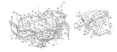
- FIG. 1is a perspective view of a patient support apparatus in a generally flat configuration with three siderail assemblies in a raised position and one siderail assembly in a first lowered position;
- FIG. 2is a perspective view of the patient support apparatus of FIG. 1 moved to a chair-egress position with one foot siderail assembly in the raised position and the other foot siderail assembly in a second lowered position;
- FIG. 3is an enlarged partial perspective view of the patient support apparatus of FIG. 1 showing a siderail mover coupled to a foot section of the patient support apparatus;
- FIGS. 4-6are a series of sectional views showing rotation of the foot section from a horizontal position to a vertical position
- FIG. 4is a sectional view taken along the line 4 - 4 of FIG. 3 with the foot section in a horizontal position and the foot siderail assembly in a first lowered position under a deck of the patient support apparatus;
- FIG. 5is a view similar to FIG. 4 with the foot section beginning to rotate downwardly and engaging the siderail assembly to move it outward towards a second lowered position as shown in FIGS. 2 and 6 ;
- FIG. 6is a view similar to FIG. 5 with the foot section continuing to rotate downwardly and maintaining the siderail assembly in the second lowered position;
- FIG. 7is an enlarged partial elevational view of another embodiment of a siderail mover in a retracted position causing a siderail assembly to be in a first lowered position;
- FIG. 8is a view similar to FIG. 7 with the siderail mover in an extended position causing the siderail assembly to be in a second lowered position.
- a patient support apparatussuch as a hospital bed 10 is shown, for example, in FIGS. 1 and 2 .
- the hospital bed 10is movable between a bed position, as shown in FIG. 1 , and a chair-egress position as shown in FIG. 2 .
- the hospital bed 10when in the bed position, provides support to a patient (not shown) such that the patient's feet are supported spaced-apart above the ground 99 .
- the hospital bed 10when in the chair-egress position, provides support to a patient such that the patient sits upright and the patient's feet are positioned on the ground 99 .
- the hospital bed 10also includes a patient-right foot siderail assembly 12 R shown in a raised position in FIGS.
- FIG. 1 and 2and a patient-left foot siderail assembly 12 L shown in a first lowered position in FIG. 1 .
- the foot siderail assemblies 12 R, 12 Lare movable between the raised and the lowered positions whether the hospital bed 10 is in the bed position or the chair-egress position.
- a pair of siderail movers 14 R, 14 Lare included in the hospital bed 10 .
- the siderail movers 14 R, 14 Lmove the foot siderail assemblies 12 R, 12 L from the first lowered position of FIG. 1 to a second lowered position of FIG. 2 so that the hospital bed 10 may assume the chair-egress position without inferring with or damaging the foot siderail assemblies 12 R, 12 L.
- the hospital bed 10further includes a frame 16 and a mattress 18 that is supported by the frame 16 as shown in FIGS. 1 and 2 .
- the hospital bed 10has a head end 20 and a foot end 22 and a longitudinal axis 23 that extends therebetween.
- the frame 16includes a base 24 and an upper frame 26 coupled to the base 24 by an elevation system 28 .
- the elevation system 28is operable to raise, lower, and tilt the upper frame 26 relative to the base 24 .
- the hospital bed 10further includes a foot panel 30 positioned adjacent the foot end 22 and a head panel 32 positioned adjacent the head end 20 .
- the foot panel 30is removable and is removed prior to moving the hospital bed 10 into the chair-egress position shown in FIG. 2 .
- the mattress 18 of the hospital bed 10includes a top surface 34 , a bottom surface 36 , and a perimeter surface 38 as shown in FIGS. 1 , 2 , and 4 - 6 .
- the upper frame 26 of the frame 16supports a deck 40 with the mattress 18 supported on the deck 40 .
- the deck 40as shown in FIGS. 1 and 2 , includes a head section 42 , a seat section 44 , and a foot section 46 .
- the head section 42moves about a first lateral pivot axis 48 relative to the upper frame 26 .
- the foot section 46moves about a second lateral pivot axis 50 relative to the upper frame 26 .
- the foot section 46is extendable and retractable to change an overall length of the foot section 46 , and therefore, to change an overall length of the deck 40 .
- the seat section 44also moves, such as by translating on the upper frame 26 , as the hospital bed 10 moves between the bed position and the chair-egress position.
- the foot section 46also translates along with the seat section 44 .
- the foot section 46lowers about the second lateral pivot axis 50 relative to the upper frame 26 and shortens in length.
- the foot section 46raises relative to the seat section 44 and increases in length.
- the head section 42extends generally vertically upwardly from the upper frame 26 and the foot section 46 extends generally downwardly from the upper frame 26 as shown in FIG. 2 .
- the seat section 44includes a foot edge 52 , an opposite head edge 54 , a first longitudinal edge 56 , a second longitudinal edge 58 , a top surface 60 , and an opposite bottom surface 62 as shown in FIG. 2 .
- the foot edge 52is spaced-apart from and opposite the head edge 54 .
- the first longitudinal edge 58is spaced-apart from and opposite the second longitudinal edge 56 .
- the first and second longitudinal edges 56 , 58extend between the head and the foot edges 52 , 54 . Together, all the edges 52 , 54 , 56 , 58 cooperate together to define a perimeter of the seat section 44 .
- the top surface 60is arranged to face in an upward direction and extend between the four edges 52 , 54 , 56 , 58 of the seat section 44 .
- the bottom surface 62is spaced-apart below the top surface 60 , is arranged to face in an opposite downward direction, and extends between the four edges 52 , 54 , 56 , 58 as suggested in FIG. 2 .
- the first lateral pivot axis 48is parallel to and between the head edge 54 and the head section 42 .
- the foot section 46includes a foot edge 64 , an opposite head edge 66 , a first longitudinal edge 70 , a second longitudinal edge 68 , a top surface 72 , and an opposite bottom surface 74 as suggested in FIG. 2 .
- the foot edge 64is spaced-apart from and opposite the head edge 66 .
- the first longitudinal edge 70is spaced-apart from and opposite the second longitudinal edge 68 .
- the first and second longitudinal edges 68 , 70extend between the head and the foot edges 64 , 66 . Together, all the edges 64 , 66 , 68 , 70 cooperate together to define a perimeter of the foot section 46 .
- the top surface 72is arranged to face in the upward direction when the hospital bed 10 is in the bed position and the top surface 72 extend between the four edges 64 , 66 , 68 , 70 of the foot section 46 .
- the bottom surface 74is spaced-apart below the top surface 72 , is arranged to face in the opposite downward direction when the hospital bed 10 is in the bed position, and extends between the four edges 64 , 66 , 68 , 70 as suggested in FIG. 1 .
- the second lateral pivot axis 50is parallel to the first lateral pivot axis 48 , the foot edge 52 of the seat section 44 , and the head edge 66 of the foot section 46 as suggested in FIG. 1 .
- the hospital bed 10also includes four siderail assemblies coupled to the upper frame 26 : a patient-right head siderail assembly 11 R, a patient-right foot siderail assembly 12 R, the patient-left head siderail assembly 11 L, and the patient-left foot siderail assembly 12 L.
- Each of the siderail assemblies 11 R, 12 L, 12 R, and 12 Lis movable between a raised position, as shown in FIGS. 1 and 2 , a first lowered position shown in FIG. 1 , and a second lowered position shown in FIG. 2 .
- the siderail assemblies 11 R, 11 L, 12 R, and 12 Lare sometimes referred to as siderails 11 R, 11 L, 12 R, and 12 L herein.
- the patient-left foot siderail 12 Lis spaced-apart from and arranged to extend along the first longitudinal edge 58 of the seat section 44 .
- the left foot siderail 12 Lis similar to the other siderails 12 R, 11 R, and 12 L, and thus, the following discussion of the left foot siderail 12 L is equally applicable to other siderails 11 R, 12 R, and 11 L.
- the siderail 12 Lincludes a barrier panel 78 and a linkage 80 that is configured to guide the barrier panel 78 during movement of the foot siderail 12 L between the raised and the lowered positions.
- the linkage 80interconnects the barrier panel 78 and the upper frame 26 to cause the barrier panel 78 to remain in a substantially vertical orientation during movement between the raised and the lowered positions. As shown in FIG.
- the hospital bed 10has a first width 131 when the siderail assemblies 12 L, 12 R are in the raised position and the hospital bed 10 has a second width 132 when the siderail assemblies 12 L, 12 R are in the first lowered position.
- the first width 131is less than the second width 132 .
- the barrier panel 78includes an outward side 86 and an oppositely facing inward side 88 . As shown in FIGS. 1 and 2 , the inward side 88 faces toward the mattress 18 and the outward side 86 faces away from the mattress 18 .
- a first user interface 90is coupled to the outward side 86 of the barrier panel 78 for use by a caregiver (not shown). As shown in FIGS. 1 and 2 , a second user interface 92 is coupled to the inward side 88 for use by a patient (not shown). Both the first and second user interfaces 90 , 92 are coupled electrically to a bed controller 94 included in the hospital bed 10 .
- the user interfaces 90 , 92allow caregivers and patients to control movement of the elevation system 28 as well as other features of the hospital bed 10 .
- the barrier panel 78also includes a foot side 114 , a head side 116 , and a top side 118 .
- the foot side 114faces the foot end 22 of the hospital bed 10 .
- the head side 116faces toward the head end 20 of the hospital bed 10 .
- the top side 118extends between and interconnects the foot side 114 and the head side 116 .
- the top side 118also extends between the inward and the outward sides 86 , 88 of the barrier panel 78 .
- the hospital bed 10also includes the pair of siderail movers 14 R and 14 L as shown in FIGS. 1 and 2 .
- the patient-left siderail mover 14 Lis similar to the patient-right siderail mover 14 R, and thus, the following discussion of the patient-left siderail mover 14 L is equally applicable to the patient-right siderail mover 14 R.
- the siderail mover 14 Lis configured to provide means for moving the barrier panel 78 , also called barrier 78 , from the first lowered position of FIG. 1 to a second lowered position of FIG.
- the siderail mover 14 Lincludes a foot-section ramp 98 that is coupled to the foot section 46 to move therewith.
- the foot-section ramp 98is coupled to the bottom surface 74 of the foot section 46 between the head edge 66 of the foot section 46 and the foot edge 64 of the foot section 46 .
- the foot-section ramp 98is extends along the first longitudinal edge 70 of the foot section 46 .
- the foot-section ramp 98includes foot-ramp surface 100 that extends away from the first longitudinal edge 70 toward the longitudinal axis 23 of the hospital bed 10 .
- the first longitudinal edge 70 of the foot sectionalso defines a first vertical plane 101 and the foot-section ramp 98 defines a foot-ramp plane 112 , also called the third plane, that cooperates with first vertical plane 101 to define a foot-ramp angle 104 of about 45 degrees therebetween and a second angle 105 that is complementary with the foot-ramp angle 104 as shown in FIG. 4 .
- the siderail mover 14 Lalso includes a siderail ramp 106 as shown in FIGS. 4-6 .
- the siderail ramp 106is coupled to the barrier panel 78 to move therewith.
- the siderail ramp 106is also coupled to the inward side 88 of the barrier panel 78 and extends from the foot side 114 toward the head side 116 along the top side 118 of the barrier panel 78 .
- the siderail ramp 106engages the foot-section ramp 98 during movement of the foot section 46 from the substantially horizontal position of FIG. 1 to the substantially vertical position of FIG. 2 to cause the siderail 12 L to move from the first lowered position of FIG. 1 to the second lowered position of FIG. 3 .
- the siderail ramp 106includes a siderail-ramp surface 108 that extends away from the inward side 88 of the barrier panel 78 toward the outward side 86 .
- the siderail-ramp surface 108defines a siderail-ramp plane 120 , also called a third plane, that cooperates with the first vertical plane 101 to define a siderail-ramp angle 110 of about 45 degrees therebetween and a second angle 121 that is complementary with the siderail-ramp angle 110 as shown in FIG. 6 .
- the siderail-ramp surface 108is generally parallel with the foot-ramp surface 100 .
- the two surfaces 108 , 100are arranged to lie in confronting relation to one another as the siderail 12 L moves from the first lowered position to the second lowered position.
- the siderail assemblies 12 L, 12 Rare moved to the first lowered position while the hospital bed 10 is in bed position.
- the foot section 46engages the siderail assembly 12 L and cause the siderail assembly 12 L to move in an outward direction 134 away from the seat section 44 a distance 136 sufficient to permit continued rotation of the foot section 46 in a first direction 96 about the lateral pivot axis 50 .
- the siderail assemblies 12 L, 12 Rmove to the second lowered position, space is established for the foot section 46 to assume the substantially vertical position.
- the hospital bed 10has a third width when the siderail assemblies 12 L, 12 R are in the second lowered position. The third width is greater than the first width 131 .
- FIGS. 7 and 8Another embodiment of a patient-left siderail mover 214 L is shown in FIGS. 7 and 8 .
- the siderail movers 14 L and 14 Rare omitted from a hospital bed 210 and replaced with the patient-left siderail mover 214 L and the patient-right siderail mover (not shown).
- the patient-left siderail mover 214 Lis similar to the patient-left siderail mover, and thus, the following discussion of patient-left siderail mover 214 L is equally applicable to the patient-right siderail mover.
- the patient-left siderail mover 214 Lis also called the siderail mover 214 L herein.
- the siderail mover 214 Lis movable from a retracted position shown in FIG. 7 to an extended position shown in FIG. 8 to cause the siderail 12 L to move from the first lowered position to the second lowered position.
- the siderail mover 14 LWhen the siderail mover 14 L is in the retracted position, the siderail mover 214 L has a first length 216 that causes the siderail 12 L to remain in the first lowered position as shown in FIG. 7 .
- the siderail mover 212 Lhas a second length 218 that causes the siderail 12 L to move to the second lowered position as shown in FIG. 8 .
- the first length 216is less than the second length 218 .
- the siderail mover 214 Lis an actuator coupled to the upper frame 26 of the hospital bed 210 .
- the actuator 214 Lis coupled electrically to the bed controller 94 .
- the bed controller 94causes the actuator to move from the retracted position of FIG. 7 to the extended position of FIG. 8 in response to movement of the foot section 46 from the substantially horizontal position to the substantially vertical position.
- the illustrative hospital beds 10 and 210are a so-called chair egress bed, in that they are movable between a bed position, as shown in FIG. 1 , and a chair-egress position as shown in FIG. 2 .
- the teachings of this disclosureare applicable to all types of hospital beds, including those that are incapable of achieving a chair-egress position. Some hospital beds are only able to move into a chair-like position, sometimes referred to by those in the art as a “cardiac chair position,” and this disclosure is equally applicable to those types of beds.
- the teachings of this disclosureare applicable to other types of patient support apparatuses such as stretchers, motorized chairs, operating room (OR) tables, specialty surgical tables such as orthopedic surgery tables, examination tables, and the like.
Landscapes
- Health & Medical Sciences (AREA)
- Nursing (AREA)
- Life Sciences & Earth Sciences (AREA)
- Animal Behavior & Ethology (AREA)
- General Health & Medical Sciences (AREA)
- Public Health (AREA)
- Veterinary Medicine (AREA)
- Invalid Beds And Related Equipment (AREA)
Abstract
Description
Claims (19)
Priority Applications (1)
| Application Number | Priority Date | Filing Date | Title |
|---|---|---|---|
| US13/889,407US8732875B2 (en) | 2010-11-03 | 2013-05-08 | Patient support apparatus with movable siderail assembly |
Applications Claiming Priority (2)
| Application Number | Priority Date | Filing Date | Title |
|---|---|---|---|
| US12/938,804US8453283B2 (en) | 2010-11-03 | 2010-11-03 | Patient support apparatus with movable siderail assembly |
| US13/889,407US8732875B2 (en) | 2010-11-03 | 2013-05-08 | Patient support apparatus with movable siderail assembly |
Related Parent Applications (1)
| Application Number | Title | Priority Date | Filing Date |
|---|---|---|---|
| US12/938,804ContinuationUS8453283B2 (en) | 2010-11-03 | 2010-11-03 | Patient support apparatus with movable siderail assembly |
Publications (2)
| Publication Number | Publication Date |
|---|---|
| US20130312186A1 US20130312186A1 (en) | 2013-11-28 |
| US8732875B2true US8732875B2 (en) | 2014-05-27 |
Family
ID=45098866
Family Applications (2)
| Application Number | Title | Priority Date | Filing Date |
|---|---|---|---|
| US12/938,804Active2031-02-23US8453283B2 (en) | 2010-11-03 | 2010-11-03 | Patient support apparatus with movable siderail assembly |
| US13/889,407ActiveUS8732875B2 (en) | 2010-11-03 | 2013-05-08 | Patient support apparatus with movable siderail assembly |
Family Applications Before (1)
| Application Number | Title | Priority Date | Filing Date |
|---|---|---|---|
| US12/938,804Active2031-02-23US8453283B2 (en) | 2010-11-03 | 2010-11-03 | Patient support apparatus with movable siderail assembly |
Country Status (2)
| Country | Link |
|---|---|
| US (2) | US8453283B2 (en) |
| EP (1) | EP2450018A3 (en) |
Cited By (7)
| Publication number | Priority date | Publication date | Assignee | Title |
|---|---|---|---|---|
| US9951904B2 (en) | 2015-03-24 | 2018-04-24 | Stryker Corporation | Rotatable seat clamps for rail clamp |
| US10426680B2 (en) | 2015-07-31 | 2019-10-01 | Hill-Rom Services, Inc. | Air bladder control of mattress/frame width expansion |
| US10470955B2 (en) | 2014-03-11 | 2019-11-12 | Hill-Rom Services, Inc. | Patient bed having translatable siderail for bed exit |
| US10478364B2 (en) | 2014-03-10 | 2019-11-19 | Stryker Corporation | Limb positioning system |
| US11052005B2 (en) | 2017-09-19 | 2021-07-06 | Stryker Corporation | Patient support apparatus with handles for patient ambulation |
| US11116680B2 (en) | 2017-09-19 | 2021-09-14 | Stryker Corporation | Patient support apparatus for controlling patient ingress and egress |
| US11160705B2 (en) | 2017-10-20 | 2021-11-02 | Stryker Corporation | Adjustable patient support apparatus for assisted egress and ingress |
Families Citing this family (5)
| Publication number | Priority date | Publication date | Assignee | Title |
|---|---|---|---|---|
| US8453283B2 (en) | 2010-11-03 | 2013-06-04 | Hill-Rom Services, Inc. | Patient support apparatus with movable siderail assembly |
| US20120124746A1 (en)* | 2010-11-22 | 2012-05-24 | Kirill Andrienko | Patient support apparatus with egress units |
| WO2017066616A1 (en) | 2015-10-14 | 2017-04-20 | Qfix Systems, Llc | Mri compatible patient trolley |
| US11737934B2 (en) | 2015-10-14 | 2023-08-29 | Qfix Systems, Llc | MRI compatible patient trolley |
| CN108743113A (en)* | 2018-07-04 | 2018-11-06 | 南通安企熙医疗科技有限公司 | A kind of nursing bed for aged |
Citations (48)
| Publication number | Priority date | Publication date | Assignee | Title |
|---|---|---|---|---|
| US4105242A (en) | 1977-03-02 | 1978-08-08 | Terbeek Howard G | Mobile chair |
| US4119342A (en) | 1977-04-29 | 1978-10-10 | Jones Claude C | Convertible chair structure |
| US4632450A (en) | 1984-11-21 | 1986-12-30 | Cambridge Technologies, Inc. | Convertible wheelchair/litter |
| US4691962A (en) | 1984-11-21 | 1987-09-08 | Cambridge Technologies, Inc. | Convertible wheelchair/litter |
| US4795214A (en) | 1984-11-21 | 1989-01-03 | Cambridge Technologies, Inc. | Convertible wheelchair/litter |
| US5060327A (en) | 1990-10-18 | 1991-10-29 | Hill-Rom Company, Inc. | Labor grips for birthing bed |
| USD336578S (en) | 1990-12-14 | 1993-06-22 | Hill-Rom Company, Inc. | Hand grip for a birthing bed |
| US5333887A (en) | 1993-11-16 | 1994-08-02 | Joe Sharp | Wheelchair/gurney |
| US5659910A (en) | 1995-08-04 | 1997-08-26 | Weiss; Norman | Wheelchair and bed with movable body supporting portions |
| US5680661A (en) | 1990-05-16 | 1997-10-28 | Hill-Rom, Inc. | Hospital bed with user care apparatus |
| US5715548A (en) | 1994-01-25 | 1998-02-10 | Hill-Rom, Inc. | Chair bed |
| US5732423A (en)* | 1995-08-04 | 1998-03-31 | Hill-Rom, Inc. | Bed side rails |
| US5842237A (en) | 1996-02-15 | 1998-12-01 | Lotecon, Llc | Convertible bed/chair with waste disposal |
| US6089593A (en) | 1997-02-10 | 2000-07-18 | Hill-Rom, Inc. | Ambulatory care chair |
| US6154899A (en) | 1998-10-19 | 2000-12-05 | Hill-Rom, Inc. | Resident transfer chair |
| US6212714B1 (en) | 1995-01-03 | 2001-04-10 | Hill-Rom, Inc. | Hospital bed and mattress having a retracting foot section |
| US6289537B1 (en) | 2000-02-09 | 2001-09-18 | Stryker Corporation | Patient support |
| US6363552B1 (en)* | 2000-03-17 | 2002-04-02 | Hill-Rom Services, Inc. | Bed siderail |
| US6374436B1 (en) | 1994-01-25 | 2002-04-23 | Hill-Rom Services, Inc. | Hospital bed |
| US6427264B1 (en) | 1999-03-19 | 2002-08-06 | Hill-Rom Services, Inc. | Gap filler for bed |
| US6470520B1 (en) | 1999-08-23 | 2002-10-29 | Hill-Rom Services, Inc. | Bed section attachment mechanism |
| US6691350B2 (en) | 1999-12-13 | 2004-02-17 | Hill-Rom Services, Inc. | Accessories for a patient support apparatus |
| US6726279B1 (en) | 1997-02-10 | 2004-04-27 | Hill-Rom Services, Inc. | Hydraulic controls for ambulatory care chair |
| US6757924B2 (en) | 1999-08-23 | 2004-07-06 | Hill-Rom Services, Inc. | Bed having a removable foot section |
| US6817363B2 (en) | 2000-07-14 | 2004-11-16 | Hill-Rom Services, Inc. | Pulmonary therapy apparatus |
| US6978499B2 (en) | 2001-05-25 | 2005-12-27 | Hill-Rom Services, Inc. | Architectural bed docking apparatus |
| US7017208B2 (en) | 1995-08-04 | 2006-03-28 | Hill-Rom Services, Inc. | Hospital bed |
| US7325265B2 (en) | 2004-07-30 | 2008-02-05 | Hill-Rom Services, Inc. | Advanced articulation system and mattress support for a bed |
| US7406729B2 (en) | 2004-07-30 | 2008-08-05 | Hill-Rom Services, Inc. | Patient support having powered adjustable width |
| US20080235872A1 (en) | 2007-03-30 | 2008-10-02 | Newkirk David C | User interface for hospital bed |
| US7458119B2 (en) | 2004-07-30 | 2008-12-02 | Hill-Rom Services, Inc. | Bed having a chair egress position |
| US7512998B2 (en) | 2006-06-15 | 2009-04-07 | Martin Manufacturing Company, Llc | Examination table |
| US7600817B2 (en) | 2004-08-16 | 2009-10-13 | Hill-Rom Services, Inc. | Chair |
| US20100005592A1 (en)* | 2008-06-27 | 2010-01-14 | Craig Poulos | Bed with modified foot deck |
| US7665166B2 (en) | 2006-06-15 | 2010-02-23 | Martin Manufacturing Company, Llc | Patient examination system |
| US7676862B2 (en) | 2004-09-13 | 2010-03-16 | Kreg Medical, Inc. | Siderail for hospital bed |
| US7690059B2 (en) | 2005-12-19 | 2010-04-06 | Stryker Corporation | Hospital bed |
| US7743441B2 (en) | 2004-09-13 | 2010-06-29 | Kreg Therapeutics, Inc. | Expandable width bed |
| US7757318B2 (en) | 2004-09-13 | 2010-07-20 | Kreg Therapeutics, Inc. | Mattress for a hospital bed |
| US7774873B2 (en) | 2006-06-15 | 2010-08-17 | Martin Manufacturing Co., Inc. | Examination table |
| US7779494B2 (en) | 2004-09-13 | 2010-08-24 | Kreg Therapeutics, Inc. | Bed having fixed length foot deck |
| US7788748B2 (en) | 2005-04-06 | 2010-09-07 | Piedmont Global Solutions, Inc. | Hospital beds with a rotating sleep surface that can translate into a chair configuration |
| US20100223727A1 (en)* | 2009-03-03 | 2010-09-09 | Hill-Rom, Services, Inc. | Person-support apparatus with movable portions |
| US20110208541A1 (en)* | 2010-02-19 | 2011-08-25 | Wilson Bradley T | Patient room and bed management apparatus and system |
| US20120073054A1 (en)* | 2010-09-28 | 2012-03-29 | O'keefe Christopher R | Hospital bed with chair lockout |
| US20120102649A1 (en) | 2010-11-03 | 2012-05-03 | O'keefe Christopher R | Patient support apparatus with movable siderail assembly |
| US20120144587A1 (en)* | 2010-12-13 | 2012-06-14 | Kirill Andrienko | Siderail assembly for patient support apparatus |
| US8266742B2 (en) | 2010-12-06 | 2012-09-18 | Hill-Rom Services, Inc. | Biometric bed configuration |
Family Cites Families (3)
| Publication number | Priority date | Publication date | Assignee | Title |
|---|---|---|---|---|
| US5394580A (en)* | 1993-06-11 | 1995-03-07 | Hill-Rom Company, Inc. | Hospital bed with three position patient side guards |
| US6978501B2 (en)* | 1995-01-31 | 2005-12-27 | Kci Licensing, Inc. | Bariatric bed apparatus and methods |
| US6779209B2 (en)* | 2000-12-29 | 2004-08-24 | Hill-Rom Services, Inc. | Bed siderail apparatus |
- 2010
- 2010-11-03USUS12/938,804patent/US8453283B2/enactiveActive
- 2011
- 2011-11-02EPEP11187464.0Apatent/EP2450018A3/ennot_activeWithdrawn
- 2013
- 2013-05-08USUS13/889,407patent/US8732875B2/enactiveActive
Patent Citations (80)
| Publication number | Priority date | Publication date | Assignee | Title |
|---|---|---|---|---|
| US4105242A (en) | 1977-03-02 | 1978-08-08 | Terbeek Howard G | Mobile chair |
| US4119342A (en) | 1977-04-29 | 1978-10-10 | Jones Claude C | Convertible chair structure |
| US4632450A (en) | 1984-11-21 | 1986-12-30 | Cambridge Technologies, Inc. | Convertible wheelchair/litter |
| US4691962A (en) | 1984-11-21 | 1987-09-08 | Cambridge Technologies, Inc. | Convertible wheelchair/litter |
| US4795214A (en) | 1984-11-21 | 1989-01-03 | Cambridge Technologies, Inc. | Convertible wheelchair/litter |
| US6725474B2 (en) | 1990-05-16 | 2004-04-27 | Hill-Rom Services, Inc. | Hospital bed |
| US5680661A (en) | 1990-05-16 | 1997-10-28 | Hill-Rom, Inc. | Hospital bed with user care apparatus |
| US5060327A (en) | 1990-10-18 | 1991-10-29 | Hill-Rom Company, Inc. | Labor grips for birthing bed |
| USD336578S (en) | 1990-12-14 | 1993-06-22 | Hill-Rom Company, Inc. | Hand grip for a birthing bed |
| US5333887A (en) | 1993-11-16 | 1994-08-02 | Joe Sharp | Wheelchair/gurney |
| US6336235B1 (en) | 1994-01-25 | 2002-01-08 | Hill-Rom Services, Inc. | Chair bed |
| US6163903A (en) | 1994-01-25 | 2000-12-26 | Hill-Rom Inc. | Chair bed |
| US6694548B2 (en) | 1994-01-25 | 2004-02-24 | Hill-Rom Services, Inc. | Hospital bed |
| US6374436B1 (en) | 1994-01-25 | 2002-04-23 | Hill-Rom Services, Inc. | Hospital bed |
| US5715548A (en) | 1994-01-25 | 1998-02-10 | Hill-Rom, Inc. | Chair bed |
| US6496993B2 (en) | 1995-01-03 | 2002-12-24 | Hill-Rom Services, Inc. | Hospital bed and mattress having a retracting foot section |
| US7216384B2 (en) | 1995-01-03 | 2007-05-15 | Hill-Rom Services, Inc. | Hospital bed and mattress having a retractable foot section |
| US7523515B2 (en) | 1995-01-03 | 2009-04-28 | Hill-Rom Services, Inc. | Hospital bed and mattress having a retractable foot section |
| US6212714B1 (en) | 1995-01-03 | 2001-04-10 | Hill-Rom, Inc. | Hospital bed and mattress having a retracting foot section |
| US7000272B2 (en) | 1995-01-03 | 2006-02-21 | Hill-Rom Services, Inc. | Hospital bed and mattress having a retractable foot section |
| US6684427B2 (en) | 1995-01-03 | 2004-02-03 | Hill-Rom Services, Inc. | Hospital bed and matress having a retractable foot section |
| US7237287B2 (en) | 1995-08-04 | 2007-07-03 | Hill-Rom Services, Inc. | Patient care bed with network |
| US7568246B2 (en) | 1995-08-04 | 2009-08-04 | Hill-Rom Services, Inc. | Bed with a networked alarm |
| US5659910A (en) | 1995-08-04 | 1997-08-26 | Weiss; Norman | Wheelchair and bed with movable body supporting portions |
| US7213279B2 (en) | 1995-08-04 | 2007-05-08 | Weismiller Matthew W | Hospital bed and mattress having extendable foot section |
| US5732423A (en)* | 1995-08-04 | 1998-03-31 | Hill-Rom, Inc. | Bed side rails |
| US7017208B2 (en) | 1995-08-04 | 2006-03-28 | Hill-Rom Services, Inc. | Hospital bed |
| US7784128B2 (en) | 1995-08-04 | 2010-08-31 | Hill-Rom Services, Inc. | Hospital bed |
| US7480951B2 (en) | 1995-08-04 | 2009-01-27 | Hill-Rom Services, Inc. | Patient care bed with network |
| US6009570A (en) | 1996-02-15 | 2000-01-04 | Hargest; Thomas S. | Convertible bed/chair with waste disposal |
| US5842237A (en) | 1996-02-15 | 1998-12-01 | Lotecon, Llc | Convertible bed/chair with waste disposal |
| US6315319B1 (en) | 1997-02-10 | 2001-11-13 | Hill-Rom Services, Inc. | Ambulatory care chair |
| US6565112B2 (en) | 1997-02-10 | 2003-05-20 | Hill-Rom Services, Inc. | Ambulatory care chair |
| US6726279B1 (en) | 1997-02-10 | 2004-04-27 | Hill-Rom Services, Inc. | Hydraulic controls for ambulatory care chair |
| US6846042B2 (en) | 1997-02-10 | 2005-01-25 | Hill-Rom Services, Inc. | Ambulatory care chair |
| US6089593A (en) | 1997-02-10 | 2000-07-18 | Hill-Rom, Inc. | Ambulatory care chair |
| US6154899A (en) | 1998-10-19 | 2000-12-05 | Hill-Rom, Inc. | Resident transfer chair |
| US6185769B1 (en) | 1998-10-19 | 2001-02-13 | Hill-Rom, Inc. | Resident transfer chair |
| US6427264B1 (en) | 1999-03-19 | 2002-08-06 | Hill-Rom Services, Inc. | Gap filler for bed |
| US7107636B2 (en) | 1999-03-19 | 2006-09-19 | Hill-Rom Services, Inc. | Gap filler for bed |
| US6704954B2 (en) | 1999-03-19 | 2004-03-16 | Hill-Rom Services, Inc. | Gap filler for bed |
| US6470520B1 (en) | 1999-08-23 | 2002-10-29 | Hill-Rom Services, Inc. | Bed section attachment mechanism |
| US6757924B2 (en) | 1999-08-23 | 2004-07-06 | Hill-Rom Services, Inc. | Bed having a removable foot section |
| US6691350B2 (en) | 1999-12-13 | 2004-02-17 | Hill-Rom Services, Inc. | Accessories for a patient support apparatus |
| US7171709B2 (en) | 1999-12-13 | 2007-02-06 | Hill-Rom Services, Inc. | Accessories for a patient support apparatus |
| US6948202B2 (en) | 1999-12-13 | 2005-09-27 | Hill-Rom Services, Inc. | Accessories for a patient support apparatus |
| US6289537B1 (en) | 2000-02-09 | 2001-09-18 | Stryker Corporation | Patient support |
| US6363552B1 (en)* | 2000-03-17 | 2002-04-02 | Hill-Rom Services, Inc. | Bed siderail |
| US7343916B2 (en) | 2000-07-14 | 2008-03-18 | Hill-Rom Services, Inc. | Pulmonary therapy apparatus |
| US6817363B2 (en) | 2000-07-14 | 2004-11-16 | Hill-Rom Services, Inc. | Pulmonary therapy apparatus |
| US7243386B2 (en) | 2001-05-25 | 2007-07-17 | Hill-Rom Services, Inc. | Docking station for patient support |
| US7636966B2 (en) | 2001-05-25 | 2009-12-29 | Hill-Rom Services, Inc. | Docking station for patient support |
| US6978499B2 (en) | 2001-05-25 | 2005-12-27 | Hill-Rom Services, Inc. | Architectural bed docking apparatus |
| US7325265B2 (en) | 2004-07-30 | 2008-02-05 | Hill-Rom Services, Inc. | Advanced articulation system and mattress support for a bed |
| US7730562B2 (en) | 2004-07-30 | 2010-06-08 | Hill-Rom Services, Inc. | Patient support having powered adjustable width |
| US7458119B2 (en) | 2004-07-30 | 2008-12-02 | Hill-Rom Services, Inc. | Bed having a chair egress position |
| US7406729B2 (en) | 2004-07-30 | 2008-08-05 | Hill-Rom Services, Inc. | Patient support having powered adjustable width |
| US7600817B2 (en) | 2004-08-16 | 2009-10-13 | Hill-Rom Services, Inc. | Chair |
| US8056160B2 (en) | 2004-09-13 | 2011-11-15 | Kreg Medical, Inc. | Siderail for hospital bed |
| US8069514B2 (en) | 2004-09-13 | 2011-12-06 | Kreg Medical, Inc. | Expandable width bed |
| US7676862B2 (en) | 2004-09-13 | 2010-03-16 | Kreg Medical, Inc. | Siderail for hospital bed |
| US7779494B2 (en) | 2004-09-13 | 2010-08-24 | Kreg Therapeutics, Inc. | Bed having fixed length foot deck |
| US7757318B2 (en) | 2004-09-13 | 2010-07-20 | Kreg Therapeutics, Inc. | Mattress for a hospital bed |
| US7743441B2 (en) | 2004-09-13 | 2010-06-29 | Kreg Therapeutics, Inc. | Expandable width bed |
| US7788748B2 (en) | 2005-04-06 | 2010-09-07 | Piedmont Global Solutions, Inc. | Hospital beds with a rotating sleep surface that can translate into a chair configuration |
| US7690059B2 (en) | 2005-12-19 | 2010-04-06 | Stryker Corporation | Hospital bed |
| US7805784B2 (en) | 2005-12-19 | 2010-10-05 | Stryker Corporation | Hospital bed |
| US7861334B2 (en) | 2005-12-19 | 2011-01-04 | Stryker Corporation | Hospital bed |
| US7774873B2 (en) | 2006-06-15 | 2010-08-17 | Martin Manufacturing Co., Inc. | Examination table |
| US7665166B2 (en) | 2006-06-15 | 2010-02-23 | Martin Manufacturing Company, Llc | Patient examination system |
| US7512998B2 (en) | 2006-06-15 | 2009-04-07 | Martin Manufacturing Company, Llc | Examination table |
| US20080235872A1 (en) | 2007-03-30 | 2008-10-02 | Newkirk David C | User interface for hospital bed |
| US20100005592A1 (en)* | 2008-06-27 | 2010-01-14 | Craig Poulos | Bed with modified foot deck |
| US20100223727A1 (en)* | 2009-03-03 | 2010-09-09 | Hill-Rom, Services, Inc. | Person-support apparatus with movable portions |
| US20110208541A1 (en)* | 2010-02-19 | 2011-08-25 | Wilson Bradley T | Patient room and bed management apparatus and system |
| US20120073054A1 (en)* | 2010-09-28 | 2012-03-29 | O'keefe Christopher R | Hospital bed with chair lockout |
| US20120102649A1 (en) | 2010-11-03 | 2012-05-03 | O'keefe Christopher R | Patient support apparatus with movable siderail assembly |
| US8453283B2 (en)* | 2010-11-03 | 2013-06-04 | Hill-Rom Services, Inc. | Patient support apparatus with movable siderail assembly |
| US8266742B2 (en) | 2010-12-06 | 2012-09-18 | Hill-Rom Services, Inc. | Biometric bed configuration |
| US20120144587A1 (en)* | 2010-12-13 | 2012-06-14 | Kirill Andrienko | Siderail assembly for patient support apparatus |
Cited By (9)
| Publication number | Priority date | Publication date | Assignee | Title |
|---|---|---|---|---|
| US10478364B2 (en) | 2014-03-10 | 2019-11-19 | Stryker Corporation | Limb positioning system |
| US10470955B2 (en) | 2014-03-11 | 2019-11-12 | Hill-Rom Services, Inc. | Patient bed having translatable siderail for bed exit |
| US9951904B2 (en) | 2015-03-24 | 2018-04-24 | Stryker Corporation | Rotatable seat clamps for rail clamp |
| US10426680B2 (en) | 2015-07-31 | 2019-10-01 | Hill-Rom Services, Inc. | Air bladder control of mattress/frame width expansion |
| US11052005B2 (en) | 2017-09-19 | 2021-07-06 | Stryker Corporation | Patient support apparatus with handles for patient ambulation |
| US11116680B2 (en) | 2017-09-19 | 2021-09-14 | Stryker Corporation | Patient support apparatus for controlling patient ingress and egress |
| US11723821B2 (en) | 2017-09-19 | 2023-08-15 | Stryker Corporation | Patient support apparatus for controlling patient ingress and egress |
| US11160705B2 (en) | 2017-10-20 | 2021-11-02 | Stryker Corporation | Adjustable patient support apparatus for assisted egress and ingress |
| US11806290B2 (en) | 2017-10-20 | 2023-11-07 | Stryker Corporation | Adjustable patient support apparatus for assisted egress and ingress |
Also Published As
| Publication number | Publication date |
|---|---|
| US20120102649A1 (en) | 2012-05-03 |
| EP2450018A2 (en) | 2012-05-09 |
| US20130312186A1 (en) | 2013-11-28 |
| EP2450018A3 (en) | 2013-05-29 |
| US8453283B2 (en) | 2013-06-04 |
Similar Documents
| Publication | Publication Date | Title |
|---|---|---|
| US8732875B2 (en) | Patient support apparatus with movable siderail assembly | |
| US8677535B2 (en) | Patient support apparatus with storable egress handles | |
| US8640285B2 (en) | Hospital bed seat section articulation for chair egress | |
| US8621688B2 (en) | Siderail assembly for patient support apparatus | |
| US5682631A (en) | Bed having a reduced-shear pivot and step deck combination | |
| US20120124746A1 (en) | Patient support apparatus with egress units | |
| US9756954B2 (en) | Siderail assembly for patient support appartatus | |
| US8413270B2 (en) | Siderail assembly for patient support apparatus | |
| US9757292B2 (en) | Piece of furniture, such as an adjustable bed, having an adjustable platform | |
| US8713727B2 (en) | Siderail assembly for patient support apparatus | |
| US5692256A (en) | Mattress for a hospital bed | |
| US6694549B2 (en) | Bed frame with reduced-shear pivot | |
| US20130086746A1 (en) | Patient support apparatus with movable siderail assembly | |
| US8341778B2 (en) | Bed gap filler and footboard pad | |
| US11471346B2 (en) | Long term care bed | |
| US9999558B2 (en) | Piece of furniture, such as an adjustable bed, having an adjustable platform | |
| WO2023064532A1 (en) | Hospital bed with foot egress | |
| JP2004525656A (en) | Epidural patient support | |
| US20250177227A1 (en) | Person support apparatuses including intubation assistance devices and methods of using the same |
Legal Events
| Date | Code | Title | Description |
|---|---|---|---|
| STCF | Information on status: patent grant | Free format text:PATENTED CASE | |
| AS | Assignment | Owner name:JPMORGAN CHASE BANK, N.A., AS COLLATERAL AGENT, ILLINOIS Free format text:SECURITY INTEREST;ASSIGNORS:ALLEN MEDICAL SYSTEMS, INC.;HILL-ROM SERVICES, INC.;ASPEN SURGICAL PRODUCTS, INC.;AND OTHERS;REEL/FRAME:036582/0123 Effective date:20150908 Owner name:JPMORGAN CHASE BANK, N.A., AS COLLATERAL AGENT, IL Free format text:SECURITY INTEREST;ASSIGNORS:ALLEN MEDICAL SYSTEMS, INC.;HILL-ROM SERVICES, INC.;ASPEN SURGICAL PRODUCTS, INC.;AND OTHERS;REEL/FRAME:036582/0123 Effective date:20150908 | |
| AS | Assignment | Owner name:JPMORGAN CHASE BANK, N.A., AS COLLATERAL AGENT, ILLINOIS Free format text:SECURITY AGREEMENT;ASSIGNORS:HILL-ROM SERVICES, INC.;ASPEN SURGICAL PRODUCTS, INC.;ALLEN MEDICAL SYSTEMS, INC.;AND OTHERS;REEL/FRAME:040145/0445 Effective date:20160921 Owner name:JPMORGAN CHASE BANK, N.A., AS COLLATERAL AGENT, IL Free format text:SECURITY AGREEMENT;ASSIGNORS:HILL-ROM SERVICES, INC.;ASPEN SURGICAL PRODUCTS, INC.;ALLEN MEDICAL SYSTEMS, INC.;AND OTHERS;REEL/FRAME:040145/0445 Effective date:20160921 | |
| MAFP | Maintenance fee payment | Free format text:PAYMENT OF MAINTENANCE FEE, 4TH YEAR, LARGE ENTITY (ORIGINAL EVENT CODE: M1551) Year of fee payment:4 | |
| AS | Assignment | Owner name:VOALTE, INC., FLORIDA Free format text:RELEASE BY SECURED PARTY;ASSIGNOR:JPMORGAN CHASE BANK, N.A.;REEL/FRAME:050254/0513 Effective date:20190830 Owner name:ANODYNE MEDICAL DEVICE, INC., FLORIDA Free format text:RELEASE BY SECURED PARTY;ASSIGNOR:JPMORGAN CHASE BANK, N.A.;REEL/FRAME:050254/0513 Effective date:20190830 Owner name:MORTARA INSTRUMENT, INC., WISCONSIN Free format text:RELEASE BY SECURED PARTY;ASSIGNOR:JPMORGAN CHASE BANK, N.A.;REEL/FRAME:050254/0513 Effective date:20190830 Owner name:HILL-ROM SERVICES, INC., ILLINOIS Free format text:RELEASE BY SECURED PARTY;ASSIGNOR:JPMORGAN CHASE BANK, N.A.;REEL/FRAME:050254/0513 Effective date:20190830 Owner name:WELCH ALLYN, INC., NEW YORK Free format text:RELEASE BY SECURED PARTY;ASSIGNOR:JPMORGAN CHASE BANK, N.A.;REEL/FRAME:050254/0513 Effective date:20190830 Owner name:MORTARA INSTRUMENT SERVICES, INC., WISCONSIN Free format text:RELEASE BY SECURED PARTY;ASSIGNOR:JPMORGAN CHASE BANK, N.A.;REEL/FRAME:050254/0513 Effective date:20190830 Owner name:HILL-ROM COMPANY, INC., ILLINOIS Free format text:RELEASE BY SECURED PARTY;ASSIGNOR:JPMORGAN CHASE BANK, N.A.;REEL/FRAME:050254/0513 Effective date:20190830 Owner name:ALLEN MEDICAL SYSTEMS, INC., ILLINOIS Free format text:RELEASE BY SECURED PARTY;ASSIGNOR:JPMORGAN CHASE BANK, N.A.;REEL/FRAME:050254/0513 Effective date:20190830 Owner name:HILL-ROM, INC., ILLINOIS Free format text:RELEASE BY SECURED PARTY;ASSIGNOR:JPMORGAN CHASE BANK, N.A.;REEL/FRAME:050254/0513 Effective date:20190830 | |
| AS | Assignment | Owner name:JPMORGAN CHASE BANK, N.A., ILLINOIS Free format text:SECURITY AGREEMENT;ASSIGNORS:HILL-ROM HOLDINGS, INC.;HILL-ROM, INC.;HILL-ROM SERVICES, INC.;AND OTHERS;REEL/FRAME:050260/0644 Effective date:20190830 | |
| MAFP | Maintenance fee payment | Free format text:PAYMENT OF MAINTENANCE FEE, 8TH YEAR, LARGE ENTITY (ORIGINAL EVENT CODE: M1552); ENTITY STATUS OF PATENT OWNER: LARGE ENTITY Year of fee payment:8 | |
| AS | Assignment | Owner name:HILL-ROM HOLDINGS, INC., ILLINOIS Free format text:RELEASE OF SECURITY INTEREST AT REEL/FRAME 050260/0644;ASSIGNOR:JPMORGAN CHASE BANK, N.A.;REEL/FRAME:058517/0001 Effective date:20211213 Owner name:BARDY DIAGNOSTICS, INC., ILLINOIS Free format text:RELEASE OF SECURITY INTEREST AT REEL/FRAME 050260/0644;ASSIGNOR:JPMORGAN CHASE BANK, N.A.;REEL/FRAME:058517/0001 Effective date:20211213 Owner name:VOALTE, INC., FLORIDA Free format text:RELEASE OF SECURITY INTEREST AT REEL/FRAME 050260/0644;ASSIGNOR:JPMORGAN CHASE BANK, N.A.;REEL/FRAME:058517/0001 Effective date:20211213 Owner name:HILL-ROM, INC., ILLINOIS Free format text:RELEASE OF SECURITY INTEREST AT REEL/FRAME 050260/0644;ASSIGNOR:JPMORGAN CHASE BANK, N.A.;REEL/FRAME:058517/0001 Effective date:20211213 Owner name:WELCH ALLYN, INC., NEW YORK Free format text:RELEASE OF SECURITY INTEREST AT REEL/FRAME 050260/0644;ASSIGNOR:JPMORGAN CHASE BANK, N.A.;REEL/FRAME:058517/0001 Effective date:20211213 Owner name:ALLEN MEDICAL SYSTEMS, INC., ILLINOIS Free format text:RELEASE OF SECURITY INTEREST AT REEL/FRAME 050260/0644;ASSIGNOR:JPMORGAN CHASE BANK, N.A.;REEL/FRAME:058517/0001 Effective date:20211213 Owner name:HILL-ROM SERVICES, INC., ILLINOIS Free format text:RELEASE OF SECURITY INTEREST AT REEL/FRAME 050260/0644;ASSIGNOR:JPMORGAN CHASE BANK, N.A.;REEL/FRAME:058517/0001 Effective date:20211213 Owner name:BREATHE TECHNOLOGIES, INC., CALIFORNIA Free format text:RELEASE OF SECURITY INTEREST AT REEL/FRAME 050260/0644;ASSIGNOR:JPMORGAN CHASE BANK, N.A.;REEL/FRAME:058517/0001 Effective date:20211213 |