US8731864B2 - System and method of sensor installation validation - Google Patents
System and method of sensor installation validationDownload PDFInfo
- Publication number
- US8731864B2 US8731864B2US13/105,022US201113105022AUS8731864B2US 8731864 B2US8731864 B2US 8731864B2US 201113105022 AUS201113105022 AUS 201113105022AUS 8731864 B2US8731864 B2US 8731864B2
- Authority
- US
- United States
- Prior art keywords
- detector
- installation
- data
- environmental condition
- setup
- Prior art date
- Legal status (The legal status is an assumption and is not a legal conclusion. Google has not performed a legal analysis and makes no representation as to the accuracy of the status listed.)
- Active, expires
Links
Images


Classifications
- G—PHYSICS
- G01—MEASURING; TESTING
- G01B—MEASURING LENGTH, THICKNESS OR SIMILAR LINEAR DIMENSIONS; MEASURING ANGLES; MEASURING AREAS; MEASURING IRREGULARITIES OF SURFACES OR CONTOURS
- G01B13/00—Measuring arrangements characterised by the use of fluids
- G—PHYSICS
- G08—SIGNALLING
- G08B—SIGNALLING OR CALLING SYSTEMS; ORDER TELEGRAPHS; ALARM SYSTEMS
- G08B13/00—Burglar, theft or intruder alarms
- G—PHYSICS
- G01—MEASURING; TESTING
- G01B—MEASURING LENGTH, THICKNESS OR SIMILAR LINEAR DIMENSIONS; MEASURING ANGLES; MEASURING AREAS; MEASURING IRREGULARITIES OF SURFACES OR CONTOURS
- G01B13/00—Measuring arrangements characterised by the use of fluids
- G01B13/02—Measuring arrangements characterised by the use of fluids for measuring length, width or thickness
- G01B13/04—Measuring arrangements characterised by the use of fluids for measuring length, width or thickness specially adapted for measuring length or width of objects while moving
- G—PHYSICS
- G08—SIGNALLING
- G08B—SIGNALLING OR CALLING SYSTEMS; ORDER TELEGRAPHS; ALARM SYSTEMS
- G08B29/00—Checking or monitoring of signalling or alarm systems; Prevention or correction of operating errors, e.g. preventing unauthorised operation
- G08B29/18—Prevention or correction of operating errors
Definitions
- the applicationpertains to ambient condition detectors, such as glassbreak detectors or motion sensors. More particularly, the application pertains to such units which include stored information relating to the unit installation process.
- Glassbreak detectors, and motion sensorssometimes have problems with false alarms and/or detection which can be attributed to incorrect or incomplete installation procedures.
- Such unitseach usually include specific installation recommendations and/or requirements that define what steps the installer should perform to validate that the installation will result in optimal performance (i.e., range and sensitivity).
- range and sensitivityi.e., range and sensitivity
- FIG. 1is a block diagram of a detector which can store information relating to its installation
- FIG. 2is a flow diagram illustrating one form of operation of a detector as in FIG. 1 .
- Dedicated non-volatile memory within the unit's circuitrycan be used to store data pertinent to the unit's setup and validation steps performed at the time of installation. The data can then be retrieved if the unit is returned due to a performance problem. On site retrieval is also possible. Retrieval of the set-up data will enable a determination to be made as to the unit's proper or improper installation. Additionally the unit can report that status locally.
- Non-volatile memorycan be provided for storing pertinent installation set-up parameters.
- the unitWhen the unit is powered up it checks to see if an installation flag data bit has been set.
- the installation flag bitcan be set when the unit is first put into test mode. If the unit was never put into test mode, and it is returned for a performance issue it can be determined that the installer failed to follow the installation instructions with regards to properly range testing the unit. If the installation flag is set then the installation verification parameters can be retrieved from memory to determine if the setup steps where performed properly.
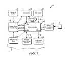
- FIG. 1is a block diagram of an embodiment of an environmental condition detector 10 in accordance herewith.
- Detector 10has a housing 12 which carries a plurality of electronic components.
- Detector 10includes one or more environmental sensors 14 , for example an acoustic sensor, such as a microphone, or a motion sensor such as an ultrasonic, microwave, or passive infrared sensor, without limitation. Buffered outputs from the sensors 14 can be coupled to analog signal conditioning circuitry 16
- Conditioned analog, or digital, outputs from circuits 16can be coupled to comparator circuits 18 , and/or to control circuits 22 which might include the comparator circuits 18 .
- Control circuits 22could be implemented, at least in part, with a programmable processor 22 a and pre-stored control programs 22 b stored on non-volatile storage circuits 22 c.
- Control circuits 22are also coupled to user input circuits 26 provided to enable a user to select installation parameters or conditions.
- a program, debug and test interface 28coupled to control circuits 22 , facilitates initial programming, debugging and testing of the detector 10 .
- Indicators 30 , or interface 28can be used after installation to determine if data stored in the non-volatile circuits 22 c indicates that detector 10 had previously been correctly installed.
- Local status indicators 30for example, audible or visual indicators such as audio output devices, LEDs, liquid crystal displays or the like, are coupled to circuits 22 and activated thereby to provide local status information.
- Status communication circuitry 32coupled to control circuits 22 , provides wired or wireless communication with a displaced regional monitoring system S as would be understood by those of skill in the art.
- FIG. 2illustrates exemplary aspects of processing 100 at the detector 10 .
- the control circuits 22can acquire and convert, as at 106 , one or more input signal values, from sensor 14 . Those signals can be processed, as at 108 , and categorized as to type of event, as a 110 .
- An alarm eventcan generate an alarm communication, as at 116 , either locally, via output devices 30 , or via communications interface 32 .
- a detected set-up eventcan be evaluated to determine if installation had been carried out as expected, as at 120 .
- Installation setup datacan be stored in, loaded into, memory 22 c , as at 122 .
- a local indication thereofcan be provided, as at 124 via output device(s) 30 .
- either or both of installation and setup data, along with logged event informationcan be provided from the memory 22 c and output via the local interface 28 , or communications interface 32 , and/or via local status indicators 30 .
- the pre-stored setup, or installation, datamakes possible after-installation reviews to evaluate the correctness of the installation process. Where a detector, such as 10 , has failed to perform, such pre-stored information may be the only indicia as to the condition of the unit when the installation was completed.
- the installation related datacan be detected and stored in real-time for later retrieval.
Landscapes
- Physics & Mathematics (AREA)
- General Physics & Mathematics (AREA)
- Engineering & Computer Science (AREA)
- Computer Security & Cryptography (AREA)
- Fire Alarms (AREA)
- Alarm Systems (AREA)
Abstract
Description
Claims (15)
Priority Applications (1)
| Application Number | Priority Date | Filing Date | Title |
|---|---|---|---|
| US13/105,022US8731864B2 (en) | 2011-05-11 | 2011-05-11 | System and method of sensor installation validation |
Applications Claiming Priority (1)
| Application Number | Priority Date | Filing Date | Title |
|---|---|---|---|
| US13/105,022US8731864B2 (en) | 2011-05-11 | 2011-05-11 | System and method of sensor installation validation |
Publications (2)
| Publication Number | Publication Date |
|---|---|
| US20120290247A1 US20120290247A1 (en) | 2012-11-15 |
| US8731864B2true US8731864B2 (en) | 2014-05-20 |
Family
ID=47142450
Family Applications (1)
| Application Number | Title | Priority Date | Filing Date |
|---|---|---|---|
| US13/105,022Active2032-03-08US8731864B2 (en) | 2011-05-11 | 2011-05-11 | System and method of sensor installation validation |
Country Status (1)
| Country | Link |
|---|---|
| US (1) | US8731864B2 (en) |
Cited By (1)
| Publication number | Priority date | Publication date | Assignee | Title |
|---|---|---|---|---|
| US11113828B2 (en) | 2016-07-22 | 2021-09-07 | Google Llc | Determining sensor installation characteristics from camera image |
Families Citing this family (2)
| Publication number | Priority date | Publication date | Assignee | Title |
|---|---|---|---|---|
| US9911317B2 (en) | 2013-10-03 | 2018-03-06 | Tyco Safety Products Canada Ltd. | Method and system for determining maintenance needs and validating the installation of an alarm system |
| US9390616B2 (en) | 2013-10-03 | 2016-07-12 | Tyco Safety Products Canada Ltd. | Method and apparatus for determining maintenance needs and validating the installation of an alarm system |
Citations (10)
| Publication number | Priority date | Publication date | Assignee | Title |
|---|---|---|---|---|
| US5414409A (en)* | 1992-07-23 | 1995-05-09 | International Electronics, Inc. | Alarm system for detecting an audio signal when glass breakage occurs |
| US5508511A (en)* | 1994-05-24 | 1996-04-16 | Interactive Light, Inc. | Arrangement for and method of detecting an object in an area subject to environmental variations |
| US5543783A (en)* | 1994-05-20 | 1996-08-06 | Caddx-Caddi Controls, Inc. | Glass break detector and a method therefor |
| US5691699A (en)* | 1996-02-08 | 1997-11-25 | Detection Systems, Inc. | Security detector with optical data transmitter |
| US5900806A (en)* | 1992-05-22 | 1999-05-04 | Issa; Darrell E. | Alarm sensor multiplexing |
| US6236313B1 (en)* | 1997-10-28 | 2001-05-22 | Pittway Corp. | Glass breakage detector |
| US20040215750A1 (en)* | 2003-04-28 | 2004-10-28 | Stilp Louis A. | Configuration program for a security system |
| US20050159911A1 (en)* | 2002-07-03 | 2005-07-21 | Tokyo Electron Limited | Method and apparatus for automatic sensor installation |
| US20060176167A1 (en)* | 2005-01-25 | 2006-08-10 | Laser Shield Systems, Inc. | Apparatus, system, and method for alarm systems |
| US20080310254A1 (en)* | 2007-06-12 | 2008-12-18 | Honeywell International, Inc. | System and method for adjusting sensitivity of an acoustic sensor |
- 2011
- 2011-05-11USUS13/105,022patent/US8731864B2/enactiveActive
Patent Citations (10)
| Publication number | Priority date | Publication date | Assignee | Title |
|---|---|---|---|---|
| US5900806A (en)* | 1992-05-22 | 1999-05-04 | Issa; Darrell E. | Alarm sensor multiplexing |
| US5414409A (en)* | 1992-07-23 | 1995-05-09 | International Electronics, Inc. | Alarm system for detecting an audio signal when glass breakage occurs |
| US5543783A (en)* | 1994-05-20 | 1996-08-06 | Caddx-Caddi Controls, Inc. | Glass break detector and a method therefor |
| US5508511A (en)* | 1994-05-24 | 1996-04-16 | Interactive Light, Inc. | Arrangement for and method of detecting an object in an area subject to environmental variations |
| US5691699A (en)* | 1996-02-08 | 1997-11-25 | Detection Systems, Inc. | Security detector with optical data transmitter |
| US6236313B1 (en)* | 1997-10-28 | 2001-05-22 | Pittway Corp. | Glass breakage detector |
| US20050159911A1 (en)* | 2002-07-03 | 2005-07-21 | Tokyo Electron Limited | Method and apparatus for automatic sensor installation |
| US20040215750A1 (en)* | 2003-04-28 | 2004-10-28 | Stilp Louis A. | Configuration program for a security system |
| US20060176167A1 (en)* | 2005-01-25 | 2006-08-10 | Laser Shield Systems, Inc. | Apparatus, system, and method for alarm systems |
| US20080310254A1 (en)* | 2007-06-12 | 2008-12-18 | Honeywell International, Inc. | System and method for adjusting sensitivity of an acoustic sensor |
Cited By (1)
| Publication number | Priority date | Publication date | Assignee | Title |
|---|---|---|---|---|
| US11113828B2 (en) | 2016-07-22 | 2021-09-07 | Google Llc | Determining sensor installation characteristics from camera image |
Also Published As
| Publication number | Publication date |
|---|---|
| US20120290247A1 (en) | 2012-11-15 |
Similar Documents
| Publication | Publication Date | Title |
|---|---|---|
| EP2997558B1 (en) | Method for self-testing notification appliances in alarm systems | |
| CN115311834B (en) | Safety equipment inspection | |
| US20130076506A1 (en) | System and Method for Testing and Calibrating Audio Detector and Other Sensing and Communications Devices | |
| EP2973481B1 (en) | Methods for inspecting and testing notification appliances in alarm systems | |
| CN102158527B (en) | Household electrical appliance maintenance system and household electrical appliance with self-checking function | |
| US7768530B2 (en) | Verification of process variable transmitter | |
| US10514288B2 (en) | Meter and method for detecton of a meter having been tampered with | |
| EP2973480B1 (en) | Method for testing notification appliances in alarm systems | |
| KR20110023765A (en) | Gas detector with visual fulfillment verification | |
| US8731864B2 (en) | System and method of sensor installation validation | |
| US11579602B2 (en) | Method for commissioning and maintenance of alarm systems | |
| US9368012B2 (en) | Detector with integrated sensor platform | |
| CN110278322A (en) | Electronic device failure test device and test method | |
| CN103366526A (en) | Online testing, check and calibration instrument for portable gas alarm system | |
| US20130241734A1 (en) | System and method for detecting improper wiring or configuration in a monitoring system | |
| CA2848554C (en) | System and method for storing and monitoring events at security devices | |
| EP3461102A1 (en) | Notification control device, notification control system, notification control method, and storage medium | |
| KR101323940B1 (en) | Apparatus and method for Alarm processing of Human Machine Interface | |
| US9697707B2 (en) | Highly directional glassbreak detector | |
| Bintang et al. | Modification Of Smoke Detector Monitoring Design Using Android Application | |
| CN105159270A (en) | Method for verifying BIT monitoring effectiveness | |
| CN120340189A (en) | Early warning method, device, electronic device and storage medium based on pyrolytic particles | |
| CN109671258A (en) | Method and device for detecting sensor in remote controller and remote controller | |
| CN108628723A (en) | Information processing method | |
| JP2011215894A (en) | Confirmation device |
Legal Events
| Date | Code | Title | Description |
|---|---|---|---|
| AS | Assignment | Owner name:HONEYWELL INTERNATIONAL INC., NEW JERSEY Free format text:ASSIGNMENT OF ASSIGNORS INTEREST;ASSIGNOR:SMITH, RICHARD ALAN;REEL/FRAME:026257/0896 Effective date:20110419 | |
| STCF | Information on status: patent grant | Free format text:PATENTED CASE | |
| MAFP | Maintenance fee payment | Free format text:PAYMENT OF MAINTENANCE FEE, 4TH YEAR, LARGE ENTITY (ORIGINAL EVENT CODE: M1551) Year of fee payment:4 | |
| AS | Assignment | Owner name:JPMORGAN CHASE BANK, N.A., AS ADMINISTRATIVE AGENT, NEW YORK Free format text:SECURITY INTEREST;ASSIGNOR:ADEMCO INC.;REEL/FRAME:047337/0577 Effective date:20181025 Owner name:JPMORGAN CHASE BANK, N.A., AS ADMINISTRATIVE AGENT Free format text:SECURITY INTEREST;ASSIGNOR:ADEMCO INC.;REEL/FRAME:047337/0577 Effective date:20181025 | |
| AS | Assignment | Owner name:ADEMCO INC., MINNESOTA Free format text:ASSIGNMENT OF ASSIGNORS INTEREST;ASSIGNOR:HONEYWELL INTERNATIONAL INC.;REEL/FRAME:047909/0425 Effective date:20181029 | |
| AS | Assignment | Owner name:ADEMCO INC., MINNESOTA Free format text:CORRECTIVE ASSIGNMENT TO CORRECT THE PREVIOUS RECORDING BY NULLIFICATION. THE INCORRECTLY RECORDED PATENT NUMBERS 8545483, 8612538 AND 6402691 PREVIOUSLY RECORDED AT REEL: 047909 FRAME: 0425. ASSIGNOR(S) HEREBY CONFIRMS THE ASSIGNMENT;ASSIGNOR:HONEYWELL INTERNATIONAL INC.;REEL/FRAME:050431/0053 Effective date:20190215 | |
| MAFP | Maintenance fee payment | Free format text:PAYMENT OF MAINTENANCE FEE, 8TH YEAR, LARGE ENTITY (ORIGINAL EVENT CODE: M1552); ENTITY STATUS OF PATENT OWNER: LARGE ENTITY Year of fee payment:8 | |
| AS | Assignment | Owner name:RESIDEO LLC, DELAWARE Free format text:CHANGE OF NAME;ASSIGNOR:ADEMCO INC.;REEL/FRAME:071546/0001 Effective date:20241227 |