US8731367B2 - Image processing apparatus - Google Patents
Image processing apparatusDownload PDFInfo
- Publication number
- US8731367B2 US8731367B2US11/680,122US68012207AUS8731367B2US 8731367 B2US8731367 B2US 8731367B2US 68012207 AUS68012207 AUS 68012207AUS 8731367 B2US8731367 B2US 8731367B2
- Authority
- US
- United States
- Prior art keywords
- frame rate
- playback
- control unit
- imaging
- images
- Prior art date
- Legal status (The legal status is an assumption and is not a legal conclusion. Google has not performed a legal analysis and makes no representation as to the accuracy of the status listed.)
- Expired - Fee Related, expires
Links
Images


Classifications
- A—HUMAN NECESSITIES
- A61—MEDICAL OR VETERINARY SCIENCE; HYGIENE
- A61B—DIAGNOSIS; SURGERY; IDENTIFICATION
- A61B6/00—Apparatus or devices for radiation diagnosis; Apparatus or devices for radiation diagnosis combined with radiation therapy equipment
- A61B6/50—Apparatus or devices for radiation diagnosis; Apparatus or devices for radiation diagnosis combined with radiation therapy equipment specially adapted for specific body parts; specially adapted for specific clinical applications
- A61B6/504—Apparatus or devices for radiation diagnosis; Apparatus or devices for radiation diagnosis combined with radiation therapy equipment specially adapted for specific body parts; specially adapted for specific clinical applications for diagnosis of blood vessels, e.g. by angiography
- A—HUMAN NECESSITIES
- A61—MEDICAL OR VETERINARY SCIENCE; HYGIENE
- A61B—DIAGNOSIS; SURGERY; IDENTIFICATION
- A61B6/00—Apparatus or devices for radiation diagnosis; Apparatus or devices for radiation diagnosis combined with radiation therapy equipment
- A61B6/46—Arrangements for interfacing with the operator or the patient
- A61B6/461—Displaying means of special interest
- H—ELECTRICITY
- H04—ELECTRIC COMMUNICATION TECHNIQUE
- H04N—PICTORIAL COMMUNICATION, e.g. TELEVISION
- H04N13/00—Stereoscopic video systems; Multi-view video systems; Details thereof
- H04N13/10—Processing, recording or transmission of stereoscopic or multi-view image signals
- H04N13/189—Recording image signals; Reproducing recorded image signals
- A—HUMAN NECESSITIES
- A61—MEDICAL OR VETERINARY SCIENCE; HYGIENE
- A61B—DIAGNOSIS; SURGERY; IDENTIFICATION
- A61B6/00—Apparatus or devices for radiation diagnosis; Apparatus or devices for radiation diagnosis combined with radiation therapy equipment
- A61B6/02—Arrangements for diagnosis sequentially in different planes; Stereoscopic radiation diagnosis
- A61B6/022—Stereoscopic imaging
- H—ELECTRICITY
- H04—ELECTRIC COMMUNICATION TECHNIQUE
- H04N—PICTORIAL COMMUNICATION, e.g. TELEVISION
- H04N2201/00—Indexing scheme relating to scanning, transmission or reproduction of documents or the like, and to details thereof
- H04N2201/32—Circuits or arrangements for control or supervision between transmitter and receiver or between image input and image output device, e.g. between a still-image camera and its memory or between a still-image camera and a printer device
- H04N2201/3201—Display, printing, storage or transmission of additional information, e.g. ID code, date and time or title
- H04N2201/3225—Display, printing, storage or transmission of additional information, e.g. ID code, date and time or title of data relating to an image, a page or a document
- H04N2201/3247—Data linking a set of images to one another, e.g. sequence, burst or continuous capture mode
- H—ELECTRICITY
- H04—ELECTRIC COMMUNICATION TECHNIQUE
- H04N—PICTORIAL COMMUNICATION, e.g. TELEVISION
- H04N2201/00—Indexing scheme relating to scanning, transmission or reproduction of documents or the like, and to details thereof
- H04N2201/32—Circuits or arrangements for control or supervision between transmitter and receiver or between image input and image output device, e.g. between a still-image camera and its memory or between a still-image camera and a printer device
- H04N2201/3201—Display, printing, storage or transmission of additional information, e.g. ID code, date and time or title
- H04N2201/3225—Display, printing, storage or transmission of additional information, e.g. ID code, date and time or title of data relating to an image, a page or a document
- H04N2201/3252—Image capture parameters, e.g. resolution, illumination conditions, orientation of the image capture device
- H—ELECTRICITY
- H04—ELECTRIC COMMUNICATION TECHNIQUE
- H04N—PICTORIAL COMMUNICATION, e.g. TELEVISION
- H04N2201/00—Indexing scheme relating to scanning, transmission or reproduction of documents or the like, and to details thereof
- H04N2201/32—Circuits or arrangements for control or supervision between transmitter and receiver or between image input and image output device, e.g. between a still-image camera and its memory or between a still-image camera and a printer device
- H04N2201/3201—Display, printing, storage or transmission of additional information, e.g. ID code, date and time or title
- H04N2201/3225—Display, printing, storage or transmission of additional information, e.g. ID code, date and time or title of data relating to an image, a page or a document
- H04N2201/3254—Orientation, e.g. landscape or portrait; Location or order of the image data, e.g. in memory
Definitions
- the present inventionrelates to an image processing apparatus which generates and displays a stereoscopic image of a blood vessel or the like from a plurality of medical images at different imaging angles.
- FIG. 19there is available a technique of designating a plurality of anatomically identical points from at least two medical images, typically X-ray images, at different imaging angles, and constructing a three-dimensional blood vessel image from the positional relationship between the designated points.
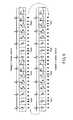
- These two X-ray imagesare preferably obtained in phase with the heart, as shown in FIG. 20 .
- Images obtained in different cardiac phasesdiffer in the three-dimensional positions of feature regions with the movement of the heart. This contradicts the major premise of the acquisition of a geometrical relationship, and hence makes it impossible to perform accurate stereoscopic construction.
- the method c)is most preferable because it can perform imaging at the same time, but cannot be practiced by facilities which have no biplane system.
- the method a)is the most general imaging method.
- the method b)is an imaging method which has recently attracted attention. This is because the method allows to simultaneously observe the stereoscopic structure of a blood vessel and its movement. The method allows to extract two suitable images from many images. The operator displays the two extracted images side by side in the same window and designates corresponding points.
- blood vessel branchesoverlap depending on extracted images, resulting in difficulty in designating corresponding regions.
- branches of a blood vesselrun in a complicated manner as in the case of the left coronary artery, in particular, branches frequently overlap.
- An error in the designation of corresponding pointsleads to an error in the construction of a spatial geometrical relationship, resulting in a deterioration in the accuracy of a stereoscopic display image. See U.S. Pat. No. 6,501,848.
- An image processing apparatus of the present inventioncomprises a storage unit which stores data of a plurality of medical images at different imaging angles with respect to the same region, a display unit which displays the data of the medical image read out from the storage unit, and a control unit which controls the storage unit and the display unit to play back the plurality of medical images as moving images and pause playback of the medical image.
- FIG. 1is a schematic view for explaining the actions and effects of an embodiment of the present invention
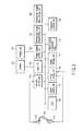
- FIG. 2is a view showing the arrangement of an X-ray diagnostic apparatus according to the embodiment
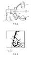
- FIG. 3is a side view of the imaging unit of the X-ray diagnostic apparatus in FIG. 2 ;
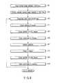
- FIG. 4is a flowchart showing a playback procedure according to this embodiment
- FIG. 5Ais a view schematically showing the procedure in FIG. 4 ;
- FIG. 5Bis a view showing the operation in FIG. 5A from the viewpoint of a change in frame rate
- FIG. 5Cis a view showing another operation in FIG. 5A from the viewpoint of a change in frame rate
- FIG. 6is a view showing a click marker in step S 05 in FIG. 4 ;
- FIG. 7is a supplementary view for step S 08 in FIG. 4 ;
- FIG. 8is a flowchart showing another playback procedure in this embodiment.
- FIG. 9is a view showing another playback loop according to this embodiment.
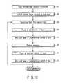
- FIG. 10is a flowchart showing another playback procedure according to this embodiment.
- FIG. 11is a flowchart showing another playback procedure according to this embodiment.
- FIG. 12is a flowchart showing another playback procedure according to this embodiment.
- FIG. 13is a flowchart showing another playback procedure according to this embodiment.
- FIG. 14is a flowchart showing another playback procedure according to this embodiment.
- FIG. 15is a supplementary view for the overall procedure in FIG. 14 ;
- FIG. 16is a flowchart showing another playback procedure according to this embodiment.
- FIGS. 17A and 17Bare views showing other image display examples according to this embodiment.
- FIG. 18is a view showing another image display example according to this embodiment.
- FIG. 19is a supplementary view for feature point designating operation in the prior art.
- FIG. 20is a view showing images displayed upon feature point designation operation in the prior art.
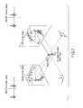
- FIGS. 21A and 21Bare views showing conventional rotating imaging operation.
- the image processing apparatuswill be described below with reference to the views of the accompanying drawing.
- the image processing apparatuswill be described as an apparatus to be incorporated in an X-ray imaging apparatus. Obviously, however, this apparatus can be configured as a standalone apparatus.
- the image processing apparatus of this embodimentis an apparatus having a function of reconstructing a three-dimensional image from images obtained by imaging from at least two directions. The type of images and the like are not specifically limited.
- This embodimenthas a unique feature for improving accuracy in manually designating anatomically identical points (corresponding points) between images for each image even in a complex structure including intricate blood vessels and the like.
- this apparatusplays back/displays a rotating moving image as a moving image at the same frame rate (1 ⁇ speed) as that at the time of imaging, and pauses images according to a predetermined rule, typically at frames corresponding to a specific cardiac phase (e.g., 80%) to display them as still images.
- a specific cardiac phasee.g., 80%
- a humanexcels in tracking a feature region on a moving image. It is easier for a human to visually track the movement of a feature region by connecting two images or two images and their preceding and succeeding images as a moving image than by simply displaying the two images as still images side by side. That is, the operator can visually track a feature region while seeing a rotating moving image. This improves the accuracy in designating corresponding feature regions even if, for example, blood vessels overlap, as compared with the case of still image display. As a consequence, it can be expected to improve the image quality of a stereoscopic image.
- cardiovascular stereoscopic displaymodeling a stereoscopic structure from projection information in a small number of directions by approximating (modeling) a blood vessel to an ellipse or polygon;
- cardiac phasea numeric value of 0 to 100% representing a cardiac cycle, which is generally calculated by dividing the period between the timing of an R wave in an electrocardiogram, which corresponds to 0, and the timing of the next R wave corresponding to 100 by 100;
- end diastolea time phase in cardiac motion in which the heart dilates and looks arrested.
- a time phase corresponding to a cardiac phase of about 70% to 80%is called a end diastole;
- rotating imagingindicates rotating an imaging system (a pair of an X-ray and a detector) around a subject. This operation is also referred to as “pivoting”. In general, a C-arm rotates at 30°/sec. Assuming that one imaging operation requires 180°, one imaging operation required six sec. Assuming that the heartbeat rate is 1/sec and this apparatus obtains one image at every 1° by imaging, the apparatus acquires medical images corresponding to six heartbeats, typically 180 X-ray images as X-ray image data, per imaging operation;
- 2Da two-dimensional image.
- An X-ray diagnostic apparatusobtains a 2D image
- 3Da three-dimensional image
- biplanean X-ray diagnostic apparatus including imaging systems of two systems, which can simultaneously perform imaging from two directions;
- ECGan electrocardiogram
- feature regiona region having a feature form of a region, e.g., a branch portion or narrowed portion of a blood vessel;
- feature pointa point designated on a feature region
- loop playbackrepeatedly playing back a series of temporally consecutive images as a moving image. After imaging, the operator often observes images by repeatedly playing back (looping) 90 frames of the images;
- respirationa process which causes the subject to move. Respiration has periodicity.
- a sensoris attached to a subject to grasp respiratory motion. In the case of MRI, a sensor may be attached to the nose;
- IVUSIntra-vascular ultrasound read as [áiv ⁇ s]
- Type A)is three-dimensional image data mainly generated by CT or MRI. Obviously, volume-reconstructed data obtained by an X-ray diagnostic apparatus corresponds to three-dimensional image data of type A.
- Three-dimensional image data of type A)has values concerning all the voxels in a three-dimensional area. More specifically, for example, 134,217,728 values are provided for a three-dimensional area of 512 ⁇ 512 ⁇ 512.
- Type B)is three-dimensional image data given as vector amount (vector data) defining a three-dimensional area, and more specifically, comprises, for example, the center line coordinates and diameter of a blood vessel.
- a display apparatuspaints an area corresponding to the center line coordinates and the diameter.
- the data amount of three-dimensional image data of type B)is much smaller than that of three-dimensional image data of type A.
- FIG. 2shows an X-ray imaging apparatus incorporating the image processing apparatus according to this embodiment.
- the X-ray imaging apparatushas the gantry shown in FIG. 3 .
- An X-ray tube 112 and an X-ray detector 114are mounted on a C-arm 116 .
- the X-ray detector 114squarely faces the X-ray tube 112 through a subject P.
- the X-ray detector 114is typically a flat panel detector comprising a two-dimensional array of detection elements (pixels) which directly or indirectly convert incident X-rays into electric charges.
- the X-ray tube 112is mounted on one end of the C-arm 116 which is supported on a floor type stand 120 so as to be biaxially rotatable.
- the X-ray detector 114is mounted on the other end of the C-arm 116 .
- the X-ray imaging apparatus equipped with the image processing apparatusincludes an electrocardiograph (ECG) 118 which measures the electrocardiogram of the subject and a gantry control unit 111 .
- ECGelectrocardiograph
- the gantry control unit 111arbitrarily controls the imaging angle of the C-arm 116 and acquire data about the imaging angle from a sensor (not shown) in accordance with operator instructions from a console 123 connecting to the gantry control unit 111 through an interface 121 .
- An image storage unit 117stores the data about the imaging angle together with X-ray image data repeatedly generated from the X-ray detector 114 through a detector control unit 115 in synchronism with X-rays generated from the X-ray tube 112 upon application of tube voltages from an X-ray control unit 113 , and cardiac phase data at the time of each X-ray imaging operation.
- Performing rotating imaging like that shown in FIGS. 21A , 21 Ballows to acquire a plurality of X-ray images whose imaging angles continuously change at 30 fps throughout an angle range of about 180°.
- This imaging periodtypically has a time length of about 10 heartbeats.
- a display unit 127is a display apparatus such as a CRT, which connects to the apparatus through an image display control unit 125 .
- a blood vessel extraction unit 119extracts a contrast image of a blood vessel obtained by, for example, threshold processing from X-ray image data.
- a playback control unit 129controls the moving image display of the display unit 127 by controlling read operation of X-ray image data stored in the image storage unit 117 . More specifically, the playback control unit 129 plays back the X-ray image data stored in the image storage unit 117 as a moving image at a frame rate (playback frame rate) of 30 fps equivalent to the frame rate (imaging frame rate) at the time of imaging operation, and pauses the display of the image at the time point when at least two X-ray images of a plurality of X-ray images which correspond to a predetermined rule during the playback period.
- a frame rateplayback frame rate
- the playback control unit 129pauses the display of at least two X-ray images which correspond to a specific cardiac phase and have an imaging angle difference of about 90°. Note that the playback control unit 129 repeatedly plays back (loop playback) a plurality of X-ray images in the forward direction coinciding with the imaging sequence.
- a stereoscopic image reconstruction unit 131reconstructs the stereoscopic image data of the blood vessel image extracted by the blood vessel extraction unit 119 from each X-ray image on the basis of the positional relationship between a plurality of feature points designed on at least two X-ray images by the operator.
- Moving image playback control performed by the playback control unit 129 to support feature point designating operationwill be described with reference to FIGS. 4 and 5A .
- the playback control unit 129calls and plays back/displays a moving image file (still image group) designated by the operator from a list of stored X-ray image data files (S 01 ). Assume that this moving image comprises a group of still images of 90 frames.
- the playback control unit 129continuously plays back 90 X-ray images at the same frame rate (playback speed (1 ⁇ )) as that at the time of imaging operation without pause (S 02 ).
- the playback control unit 129starts playing back 90 X-ray images in the forward direction from the first image, and pauses the playback/display of an X-ray image corresponding to a cardiac phase (e.g., 80%) at a end diastole of the heart as a specific cardiac phase which comes first (S 03 and S 04 ).
- a cardiac phasee.g., 80%
- the image storage unit 117 or a memorystores the data of the clicked image coordinates (S 06 ).
- the playback control unit 129resumes playing back/displaying with a predetermined time lag of about 1 sec (S 07 ).
- the playback control unit 129pauses the playback/display of an X-ray image which corresponds to the same cardiac phase as that of the previously paused X-ray image and exhibits an imaging angle difference of about 90° with respect to the previously paused X-ray image, as shown in FIG. 7 (S 08 ).
- the playback control unit 129pauses the playback/display of an X-ray image exhibiting an imaging angle difference of 90° ⁇ 10° with respect to the previously paused X-ray image.
- the playback control unit 129skips pausing an X-ray image which corresponds to the same cardiac phase as that of the previously paused X-ray image but exhibits an imaging angle difference falling outside about 90° with respect to the previously paused X-ray image, and continues playback/display at 1 ⁇ .
- the data of the clicked image coordinatesis stored (S 10 ).
- the playback control unit 129resumes playback/display and returns to step S 03 .
- the playback control unit 129pauses and plays back images in the same manner as described above. In this case, however, the playback control unit 129 stores, in the memory, the coordinates acquired at this time as the second feature region coordinates different from the previous feature region.
- the playback control unit 129stops the playback.
- a stereoscopic image reconstruction unit 131constructs stereoscopic image data concerning the blood vessel area extracted by the blood vessel extraction unit 119 .
- a stereoscopic image data storage unit 132stores the constructed data of the stereoscopic image of the blood vessel.
- FIG. 5Bshows temporal changes in playback frame rate.
- the playback control unit 129starts playing back/displaying a moving image at almost the same frame rate (1 ⁇ ) as that at the time of imaging operation.
- the playback control unit 129pauses the playback at a specific cardiac phase (e.g., 80%). Thereafter, when the operator clicks a feature point, the playback control unit 129 resumes 1 ⁇ playback. Letting ⁇ t1, ⁇ t2, . . .
- the playback frame ratechanges between the same frame rate as that at the time of imaging operation and a low frame rate ((1/ ⁇ t1, 1/ ⁇ t2, . . . ) obtained as the reciprocal of a pause period.
- a low frame rate((1/ ⁇ t1, 1/ ⁇ t2, . . . ) obtained as the reciprocal of a pause period.
- Repeating playback/pause in this mannermakes it possible to accurately designate a feature region by using the human ability of tracking a feature region on a moving image. Therefore, it can be expected to improve the image quality of a stereoscopic image.
- a specific cardiac phaseneed not be a diastolic phase of the heart, and an arbitrary cardiac phase designated by the operator may be used.
- the operatordesignates one feature point at one pause. However, it suffices to designate a plurality of feature points. Assume that two points are to be designated. In this case, when the operator clicks the mouse on two portions, the playback control unit 129 automatically terminates the pause and automatically resumes playback/display after a predetermined time lag. In addition, the playback control unit 129 may resume playback when the operator presses the playback start button or a button on the keyboard instead of automatically resuming playback after mouse clicking. The operator may use an arbitrary device such as a touch panel other than the mouse.
- the imaging angle difference between X-ray images to be pausedneed not be about 90°, and can be arbitrarily designated.
- the number of loops(the number of times of repetitive playback) is arbitrary. That is, the playback control unit 129 repeats loops until the desired number of pairs of feature regions are obtained. For example, when the operator presses a specific key on the keyboard, the playback control unit 129 terminates playback.
- a reference signal to be usedis not limited to an electrocardiographic signal. It suffices to identify a cardiac phase in the same manner as described above from the periodic movement of the peak point of a line image obtained by projecting an X-ray image in one direction as “the periodic movement of a feature region on an image”. It suffices to use a respiratory phase instead of a cardiac phase.
- the number of directions (frames) in which images are to be pausedis not limited to two. It suffices to pause X-ray images of three or more frames, of 90 frames, which satisfy a predetermined rule. Furthermore, it suffices to simply pause images in specific phases, e.g., all diastolic phases (80%), without setting any conditions concerning imaging angle differences. There is no need to set a single specific phase. It suffices to pause in two or more kinds of specific phases, e.g., all diastolic phases (80%) and all contraction phases (15%).
- a diastolic phase (80%) of the heartmay be set as a specified value.
- the operatormay arbitrarily designate a specific cardiac phase in advance.
- the operatormay manually pause playback in the second loop (S 11 ), and the playback control unit 129 may automatically pause playback in the loops from the second loop at the corresponding cardiac phase as a specific phase (S 12 ).
- moving imagesare played back in the same forward direction as the imaging sequence, and this operation is repeated.
- FIG. 9it suffices to play back moving images in the same forward direction as the imaging sequence, then play back moving images in the reverse direction, and alternately change the playback directions in this manner.
- This methodallows the operator to observe motion from two directions, and hence improves the accuracy even if feature regions overlaps, because a human tries to interpolate.
- the present inventionmay be simply used for observation for diagnosis. In this case, it suffices to cause the operator to designate pause cancellation (playback resumption) or as shown in FIG. 10 , automatically resume playback when a predetermined period of time (e.g., five sec) elapses after pause (S 13 and S 14 ).
- a predetermined period of timee.g., five sec
- an interval Ais a period (70 to 100%) including a contraction phase, in which the cardiac motion is relatively large
- an interval Bis a period (0 to 69%) including a diastolic phase of the heart, in which the cardiac motion is relatively small and hence is easy to observe, as shown in FIGS. 14 and 15 .
- playbackis performed slowly at a rate (e.g., 20 fps) lower than the rate (30 fps) at the time of imaging operation.
- the interval Bin which the cardiac motion is relatively small, images are played back at 1 ⁇ speed (S 21 and S 22 ).
- imagesare played back slowly.
- the embodimentcan be applied to the display of images obtained by an intra-vascular ultrasound apparatus (IVUS).
- IVUSis generally used to display a plurality of 2D ultrasound images by inserting the IVUS into a blood vessel and moving it at a predetermined speed (e.g., 1 mm/sec), assuming that the acquisition rate is 1 frame/sec. That is, the frames of ultrasound images are made to correspond to the moving distance.
- a predetermined speede.g., 1 mm/sec
- pausing playback at every 20th frameis equivalent to pausing playback at intervals of 2 cm (S 23 ).
- fly-through displayin which the forward field of view of reconstructed images obtained by X-ray CT or MRI is displayed as a moving image while the viewpoint is moved within a blood vessel as shown in FIG. 18 , pausing playback at predetermined distance intervals makes it possible to provide a better sense of distance.
Landscapes
- Health & Medical Sciences (AREA)
- Life Sciences & Earth Sciences (AREA)
- Engineering & Computer Science (AREA)
- Medical Informatics (AREA)
- Molecular Biology (AREA)
- Surgery (AREA)
- High Energy & Nuclear Physics (AREA)
- Physics & Mathematics (AREA)
- Nuclear Medicine, Radiotherapy & Molecular Imaging (AREA)
- Optics & Photonics (AREA)
- Pathology (AREA)
- Radiology & Medical Imaging (AREA)
- Biomedical Technology (AREA)
- Heart & Thoracic Surgery (AREA)
- Veterinary Medicine (AREA)
- Biophysics (AREA)
- Animal Behavior & Ethology (AREA)
- General Health & Medical Sciences (AREA)
- Public Health (AREA)
- Human Computer Interaction (AREA)
- Vascular Medicine (AREA)
- Dentistry (AREA)
- Oral & Maxillofacial Surgery (AREA)
- Multimedia (AREA)
- Signal Processing (AREA)
- Apparatus For Radiation Diagnosis (AREA)
- Ultra Sonic Daignosis Equipment (AREA)
- Magnetic Resonance Imaging Apparatus (AREA)
Abstract
Description
Claims (15)
Applications Claiming Priority (2)
| Application Number | Priority Date | Filing Date | Title |
|---|---|---|---|
| JP2006-055291 | 2006-03-01 | ||
| JP2006055291 | 2006-03-01 |
Publications (2)
| Publication Number | Publication Date |
|---|---|
| US20070248319A1 US20070248319A1 (en) | 2007-10-25 |
| US8731367B2true US8731367B2 (en) | 2014-05-20 |
Family
ID=38619552
Family Applications (1)
| Application Number | Title | Priority Date | Filing Date |
|---|---|---|---|
| US11/680,122Expired - Fee RelatedUS8731367B2 (en) | 2006-03-01 | 2007-02-28 | Image processing apparatus |
Country Status (2)
| Country | Link |
|---|---|
| US (1) | US8731367B2 (en) |
| JP (2) | JP2012075950A (en) |
Cited By (2)
| Publication number | Priority date | Publication date | Assignee | Title |
|---|---|---|---|---|
| US20120327186A1 (en)* | 2010-03-17 | 2012-12-27 | Fujifilm Corporation | Endoscopic observation supporting system, method, device and program |
| US20150145987A1 (en)* | 2012-05-24 | 2015-05-28 | Mitsubishi Electric Engineering Co., Ltd. | Imaging apparatus and imaging method |
Families Citing this family (12)
| Publication number | Priority date | Publication date | Assignee | Title |
|---|---|---|---|---|
| DK1665769T3 (en) | 2003-09-12 | 2014-06-30 | Opentv Inc | Method and system for controlling recording and playback of interactive applications |
| US8335357B2 (en)* | 2005-03-04 | 2012-12-18 | Kabushiki Kaisha Toshiba | Image processing apparatus |
| US8798227B2 (en) | 2010-10-15 | 2014-08-05 | Kabushiki Kaisha Toshiba | Medical image processing apparatus and X-ray computed tomography apparatus |
| WO2012050166A1 (en)* | 2010-10-15 | 2012-04-19 | 株式会社 東芝 | Medical image-processing apparatus and x-ray computer tomography apparatus |
| JP6042096B2 (en)* | 2012-05-09 | 2016-12-14 | 東芝メディカルシステムズ株式会社 | X-ray imaging apparatus and medical image processing apparatus |
| JP2016034451A (en) | 2014-08-04 | 2016-03-17 | 株式会社東芝 | X-ray diagnostic equipment |
| JP6457106B2 (en) | 2015-10-01 | 2019-01-23 | 富士フイルム株式会社 | Acoustic wave diagnostic apparatus and control method thereof |
| CN114903591A (en)* | 2016-03-21 | 2022-08-16 | 华盛顿大学 | Virtual reality or augmented reality visualization of 3D medical images |
| CN112584738B (en)* | 2018-08-30 | 2024-04-23 | 奥林巴斯株式会社 | Recording device, image observation device, observation system, control method of observation system, and storage medium |
| JP2022023826A (en)* | 2020-07-27 | 2022-02-08 | キヤノンメディカルシステムズ株式会社 | Medical image processing device, system, and method |
| CN113017691A (en)* | 2021-03-08 | 2021-06-25 | 苏州大学附属儿童医院 | Ultrasonic three-dimensional imaging scanning device |
| WO2023100838A1 (en)* | 2021-11-30 | 2023-06-08 | テルモ株式会社 | Computer program, information processing device, information processing method, and training model generation method |
Citations (26)
| Publication number | Priority date | Publication date | Assignee | Title |
|---|---|---|---|---|
| JPH02156778A (en) | 1988-12-09 | 1990-06-15 | Nippon Aidento Gurafu Kk | Consecutive stereoscopic photograph observing device |
| JPH02266475A (en) | 1989-04-07 | 1990-10-31 | Hitachi Medical Corp | Display device for medical image |
| JPH05184576A (en) | 1992-01-14 | 1993-07-27 | Ken Ishihara | Ultrasonic diagnostic device |
| JPH0779959A (en) | 1993-09-14 | 1995-03-28 | Toshiba Corp | X-ray diagnostic device |
| JPH08131429A (en) | 1994-11-11 | 1996-05-28 | Toshiba Corp | Tubular body image reproducing method and apparatus |
| US5614960A (en)* | 1992-09-07 | 1997-03-25 | Fujitsu Limited | Image data encoding method and device, image data reconstructing method and device, scene change detecting method and device, scene change recording device, and image data scene change record/regenerating device |
| JPH1099323A (en) | 1996-09-26 | 1998-04-21 | Hitachi Medical Corp | X-ray ct system |
| JPH10272136A (en) | 1997-03-31 | 1998-10-13 | Toshiba Corp | Ultrasound diagnostic equipment |
| US6047080A (en) | 1996-06-19 | 2000-04-04 | Arch Development Corporation | Method and apparatus for three-dimensional reconstruction of coronary vessels from angiographic images |
| JP2001120547A (en) | 1999-10-27 | 2001-05-08 | Hitachi Medical Corp | Ultrasonograph |
| US20020111973A1 (en)* | 1998-10-15 | 2002-08-15 | John Maddalozzo | Method of controlling web browser document image downloads and displays |
| US20020154801A1 (en)* | 2001-03-06 | 2002-10-24 | Satoru Ohishi | X-ray diagnostic apparatus and image processor |
| JP2002336222A (en) | 2001-03-06 | 2002-11-26 | Toshiba Corp | X-ray diagnostic apparatus and image processing apparatus |
| JP2002351293A (en) | 2001-05-22 | 2002-12-06 | Yoriaki Yamai | Motion analysis method |
| US20030123606A1 (en)* | 2001-12-19 | 2003-07-03 | Sabine Mollus | Method of assisting orientation in a vascular system |
| JP2004008304A (en) | 2002-06-04 | 2004-01-15 | Hitachi Ltd | Method for generating and displaying three-dimensional shape using projected images in multiple directions |
| US6685642B1 (en)* | 2002-10-03 | 2004-02-03 | Koninklijke Philips Electronics N.V. | System and method for brightening a curve corresponding to a selected ultrasound ROI |
| US20040066389A1 (en)* | 2002-10-03 | 2004-04-08 | Koninklijke Philips Electronics N.V | System and method for automatically generating a series of ultrasound images each representing the same point in a physiologic periodic waveform |
| JP2004313545A (en) | 2003-04-17 | 2004-11-11 | Hitachi Medical Corp | Cardiac motion display method and image diagnostic apparatus |
| WO2005020155A1 (en) | 2003-08-21 | 2005-03-03 | Philips Intellectual Property & Standards Gmbh | Device and method for generating a three-dimensional vascular model |
| JP2005528157A (en) | 2002-06-04 | 2005-09-22 | コーニンクレッカ フィリップス エレクトロニクス エヌ ヴィ | Hybrid 3D reconstruction of coronary artery structure based on rotational angiography |
| US20050220264A1 (en) | 2004-03-31 | 2005-10-06 | Siemens Aktiengesellschaft | Method and device for medical image reconstruction |
| JP2005312775A (en) | 2004-04-30 | 2005-11-10 | Canon Inc | Radiographic image acquisition apparatus, radiographic image display apparatus and methods thereof |
| US20060210147A1 (en) | 2005-03-04 | 2006-09-21 | Takuya Sakaguchi | Image processing apparatus |
| JP2007029487A (en) | 2005-07-28 | 2007-02-08 | Yokogawa Electric Corp | Medical image data processing apparatus and medical image data processing method |
| US7215801B2 (en)* | 2003-06-05 | 2007-05-08 | General Electric Company | Method, system and apparatus for processing radiographic images of scanned objects |
Family Cites Families (2)
| Publication number | Priority date | Publication date | Assignee | Title |
|---|---|---|---|---|
| US6369812B1 (en)* | 1997-11-26 | 2002-04-09 | Philips Medical Systems, (Cleveland), Inc. | Inter-active viewing system for generating virtual endoscopy studies of medical diagnostic data with a continuous sequence of spherical panoramic views and viewing the studies over networks |
| US6231510B1 (en)* | 1999-03-05 | 2001-05-15 | Atl Ultrasound | Ultrasonic diagnostic imaging system |
- 2007
- 2007-02-28USUS11/680,122patent/US8731367B2/ennot_activeExpired - Fee Related
- 2012
- 2012-01-26JPJP2012013931Apatent/JP2012075950A/enactivePending
- 2012-08-13JPJP2012179544Apatent/JP5550689B2/ennot_activeExpired - Fee Related
Patent Citations (28)
| Publication number | Priority date | Publication date | Assignee | Title |
|---|---|---|---|---|
| JPH02156778A (en) | 1988-12-09 | 1990-06-15 | Nippon Aidento Gurafu Kk | Consecutive stereoscopic photograph observing device |
| US5034987A (en)* | 1988-12-09 | 1991-07-23 | Nippon Identograph Co., Ltd. | Continuous photographing and observing of a three-dimensional image |
| JPH02266475A (en) | 1989-04-07 | 1990-10-31 | Hitachi Medical Corp | Display device for medical image |
| JPH05184576A (en) | 1992-01-14 | 1993-07-27 | Ken Ishihara | Ultrasonic diagnostic device |
| US5614960A (en)* | 1992-09-07 | 1997-03-25 | Fujitsu Limited | Image data encoding method and device, image data reconstructing method and device, scene change detecting method and device, scene change recording device, and image data scene change record/regenerating device |
| JPH0779959A (en) | 1993-09-14 | 1995-03-28 | Toshiba Corp | X-ray diagnostic device |
| JPH08131429A (en) | 1994-11-11 | 1996-05-28 | Toshiba Corp | Tubular body image reproducing method and apparatus |
| US6501848B1 (en) | 1996-06-19 | 2002-12-31 | University Technology Corporation | Method and apparatus for three-dimensional reconstruction of coronary vessels from angiographic images and analytical techniques applied thereto |
| US6047080A (en) | 1996-06-19 | 2000-04-04 | Arch Development Corporation | Method and apparatus for three-dimensional reconstruction of coronary vessels from angiographic images |
| JPH1099323A (en) | 1996-09-26 | 1998-04-21 | Hitachi Medical Corp | X-ray ct system |
| JPH10272136A (en) | 1997-03-31 | 1998-10-13 | Toshiba Corp | Ultrasound diagnostic equipment |
| US20020111973A1 (en)* | 1998-10-15 | 2002-08-15 | John Maddalozzo | Method of controlling web browser document image downloads and displays |
| JP2001120547A (en) | 1999-10-27 | 2001-05-08 | Hitachi Medical Corp | Ultrasonograph |
| US20020154801A1 (en)* | 2001-03-06 | 2002-10-24 | Satoru Ohishi | X-ray diagnostic apparatus and image processor |
| JP2002336222A (en) | 2001-03-06 | 2002-11-26 | Toshiba Corp | X-ray diagnostic apparatus and image processing apparatus |
| JP2002351293A (en) | 2001-05-22 | 2002-12-06 | Yoriaki Yamai | Motion analysis method |
| US20030123606A1 (en)* | 2001-12-19 | 2003-07-03 | Sabine Mollus | Method of assisting orientation in a vascular system |
| JP2004008304A (en) | 2002-06-04 | 2004-01-15 | Hitachi Ltd | Method for generating and displaying three-dimensional shape using projected images in multiple directions |
| JP2005528157A (en) | 2002-06-04 | 2005-09-22 | コーニンクレッカ フィリップス エレクトロニクス エヌ ヴィ | Hybrid 3D reconstruction of coronary artery structure based on rotational angiography |
| US6685642B1 (en)* | 2002-10-03 | 2004-02-03 | Koninklijke Philips Electronics N.V. | System and method for brightening a curve corresponding to a selected ultrasound ROI |
| US20040066389A1 (en)* | 2002-10-03 | 2004-04-08 | Koninklijke Philips Electronics N.V | System and method for automatically generating a series of ultrasound images each representing the same point in a physiologic periodic waveform |
| JP2004313545A (en) | 2003-04-17 | 2004-11-11 | Hitachi Medical Corp | Cardiac motion display method and image diagnostic apparatus |
| US7215801B2 (en)* | 2003-06-05 | 2007-05-08 | General Electric Company | Method, system and apparatus for processing radiographic images of scanned objects |
| WO2005020155A1 (en) | 2003-08-21 | 2005-03-03 | Philips Intellectual Property & Standards Gmbh | Device and method for generating a three-dimensional vascular model |
| US20050220264A1 (en) | 2004-03-31 | 2005-10-06 | Siemens Aktiengesellschaft | Method and device for medical image reconstruction |
| JP2005312775A (en) | 2004-04-30 | 2005-11-10 | Canon Inc | Radiographic image acquisition apparatus, radiographic image display apparatus and methods thereof |
| US20060210147A1 (en) | 2005-03-04 | 2006-09-21 | Takuya Sakaguchi | Image processing apparatus |
| JP2007029487A (en) | 2005-07-28 | 2007-02-08 | Yokogawa Electric Corp | Medical image data processing apparatus and medical image data processing method |
Non-Patent Citations (9)
| Title |
|---|
| Japanese Decision of Dismissal of Amendment issued Sep. 18, 2012, in Japan Patent Application No. 2007-050701 (with English translation). |
| Japanese Decision of Rejection issued Sep. 18, 2012, in Japan Patent Application No. 2007-050701 (with English translation). |
| Office Action issued Jun. 12, 2012 in Japanese Application No. 2007-050701 (With English Translation). |
| Office Action issued Nov. 29, 2011, in Japanese Patent Application No. 2007-050701 (with English-language translation). |
| Office Action mailed Aug. 6, 2013, in Japanese Patent Application No. 2012-013931 (with English-language Translation). |
| Office Action mailed Jan. 7, 2014, in Japanese Patent Application No. 2012-179544 (with English-language Translation). |
| Office Action mailed Sep. 10, 2013, in Japanese Patent Application No. 2012-179544 (with English Translation). |
| U.S. Appl. No. 11/608,005, filed Dec. 7, 2006, Takuya Sakaguchi, et al. |
| U.S. Appl. No. 11/844,048, filed Aug. 23, 2007, Sakaguchi, et al. |
Cited By (4)
| Publication number | Priority date | Publication date | Assignee | Title |
|---|---|---|---|---|
| US20120327186A1 (en)* | 2010-03-17 | 2012-12-27 | Fujifilm Corporation | Endoscopic observation supporting system, method, device and program |
| US9179822B2 (en)* | 2010-03-17 | 2015-11-10 | Fujifilm Corporation | Endoscopic observation supporting system, method, device and program |
| US20150145987A1 (en)* | 2012-05-24 | 2015-05-28 | Mitsubishi Electric Engineering Co., Ltd. | Imaging apparatus and imaging method |
| US9746318B2 (en)* | 2012-05-24 | 2017-08-29 | Mitsubishi Electric Engineering Company, Limited | Imaging apparatus and imaging method |
Also Published As
| Publication number | Publication date |
|---|---|
| JP2012213659A (en) | 2012-11-08 |
| JP2012075950A (en) | 2012-04-19 |
| US20070248319A1 (en) | 2007-10-25 |
| JP5550689B2 (en) | 2014-07-16 |
Similar Documents
| Publication | Publication Date | Title |
|---|---|---|
| US8731367B2 (en) | Image processing apparatus | |
| JP4495109B2 (en) | X-ray CT system | |
| EP1088517B1 (en) | Method and apparatus for motion-free cardiac CT imaging | |
| US7315605B2 (en) | Method and device for reconstructing a 3D image data set of a moving object | |
| US7426256B2 (en) | Motion-corrected three-dimensional volume imaging method | |
| JP4436601B2 (en) | Method and apparatus for minimizing artifacts due to poor temporal alignment in gated CT images | |
| US20120093278A1 (en) | Medical image processing apparatus and x-ray computed tomography apparatus | |
| JP5121173B2 (en) | 3D image generator | |
| JP5643218B2 (en) | X-ray CT apparatus and image display method using X-ray CT apparatus | |
| JP5204120B2 (en) | Reconstruction window adaptation in ECG gated computer tomography | |
| JP4429677B2 (en) | CT imaging method for periodically moving organs | |
| JP4157302B2 (en) | X-ray CT system | |
| CN103239253A (en) | Medical image diagnostic apparatus | |
| JP2005322252A (en) | Medical image display and image processing method, computer tomography apparatus, workstation and computer program product | |
| US20090297005A1 (en) | Operating method for a pivotal poly-plane imaging unit for imaging a moving examination object | |
| JP2012000135A (en) | Multi-modality dynamic image diagnostic apparatus | |
| JP5523656B2 (en) | Image processing device | |
| US8855391B2 (en) | Operating method for an imaging system for the time-resolved mapping of an iteratively moving examination object | |
| JP4777164B2 (en) | HEART RATE DETERMINATION DEVICE, PROGRAM, AND X-RAY DIAGNOSIS DEVICE | |
| WO2004071301A1 (en) | X-ray ct device | |
| JP5041779B2 (en) | Organ imaging method and apparatus | |
| JP2001148005A (en) | Method for reconstructing three-dimensional image of moving object | |
| JP5280168B2 (en) | X-ray CT system | |
| JP2008228829A (en) | Synchronous calculation device for periodic motion and synchronous calculation method for periodic motion | |
| JP2004313513A (en) | X-ray ct apparatus |
Legal Events
| Date | Code | Title | Description |
|---|---|---|---|
| AS | Assignment | Owner name:KABUSHIKI KAISHA TOSHIBA, JAPAN Free format text:ASSIGNMENT OF ASSIGNORS INTEREST;ASSIGNOR:SAKAGUCHI, TAKUYA;REEL/FRAME:018941/0687 Effective date:20070222 Owner name:TOSHIBA MEDICAL SYSTEMS CORPORATION, JAPAN Free format text:ASSIGNMENT OF ASSIGNORS INTEREST;ASSIGNOR:SAKAGUCHI, TAKUYA;REEL/FRAME:018941/0687 Effective date:20070222 | |
| STCF | Information on status: patent grant | Free format text:PATENTED CASE | |
| FEPP | Fee payment procedure | Free format text:PAYOR NUMBER ASSIGNED (ORIGINAL EVENT CODE: ASPN); ENTITY STATUS OF PATENT OWNER: LARGE ENTITY | |
| AS | Assignment | Owner name:TOSHIBA MEDICAL SYSTEMS CORPORATION, JAPAN Free format text:ASSIGNMENT OF ASSIGNORS INTEREST;ASSIGNOR:KABUSHIKI KAISHA TOSHIBA;REEL/FRAME:038891/0693 Effective date:20160316 | |
| MAFP | Maintenance fee payment | Free format text:PAYMENT OF MAINTENANCE FEE, 4TH YEAR, LARGE ENTITY (ORIGINAL EVENT CODE: M1551) Year of fee payment:4 | |
| FEPP | Fee payment procedure | Free format text:MAINTENANCE FEE REMINDER MAILED (ORIGINAL EVENT CODE: REM.); ENTITY STATUS OF PATENT OWNER: LARGE ENTITY | |
| LAPS | Lapse for failure to pay maintenance fees | Free format text:PATENT EXPIRED FOR FAILURE TO PAY MAINTENANCE FEES (ORIGINAL EVENT CODE: EXP.); ENTITY STATUS OF PATENT OWNER: LARGE ENTITY | |
| STCH | Information on status: patent discontinuation | Free format text:PATENT EXPIRED DUE TO NONPAYMENT OF MAINTENANCE FEES UNDER 37 CFR 1.362 | |
| FP | Lapsed due to failure to pay maintenance fee | Effective date:20220520 |