US8730640B2 - DC pass RF protector having a surge suppression module - Google Patents
DC pass RF protector having a surge suppression moduleDownload PDFInfo
- Publication number
- US8730640B2 US8730640B2US13/105,430US201113105430AUS8730640B2US 8730640 B2US8730640 B2US 8730640B2US 201113105430 AUS201113105430 AUS 201113105430AUS 8730640 B2US8730640 B2US 8730640B2
- Authority
- US
- United States
- Prior art keywords
- cavity
- housing
- surge
- spiral inductor
- conductor
- Prior art date
- Legal status (The legal status is an assumption and is not a legal conclusion. Google has not performed a legal analysis and makes no representation as to the accuracy of the status listed.)
- Expired - Fee Related, expires
Links
- 230000001012protectorEffects0.000titleclaimsdescription69
- 230000001629suppressionEffects0.000titledescription4
- 239000004020conductorSubstances0.000claimsabstractdescription89
- 239000003990capacitorSubstances0.000claimsabstractdescription32
- 239000000463materialSubstances0.000claimsdescription8
- 238000004891communicationMethods0.000claimsdescription4
- 229910052751metalInorganic materials0.000claimsdescription3
- 239000002184metalSubstances0.000claimsdescription3
- BQCADISMDOOEFD-UHFFFAOYSA-NSilverChemical compound[Ag]BQCADISMDOOEFD-UHFFFAOYSA-N0.000claimsdescription2
- 229910044991metal oxideInorganic materials0.000claimsdescription2
- 150000004706metal oxidesChemical class0.000claimsdescription2
- 229910052709silverInorganic materials0.000claimsdescription2
- 239000004332silverSubstances0.000claimsdescription2
- 238000010586diagramMethods0.000description10
- 230000005540biological transmissionEffects0.000description7
- 230000001902propagating effectEffects0.000description5
- 230000000903blocking effectEffects0.000description4
- 230000008901benefitEffects0.000description3
- 238000003780insertionMethods0.000description3
- 230000037431insertionEffects0.000description3
- 230000000116mitigating effectEffects0.000description3
- 230000015556catabolic processEffects0.000description2
- 238000000034methodMethods0.000description2
- 2299100008537075 T6 aluminium alloyInorganic materials0.000description1
- 230000002159abnormal effectEffects0.000description1
- 230000002457bidirectional effectEffects0.000description1
- 230000008859changeEffects0.000description1
- 230000008878couplingEffects0.000description1
- 238000010168coupling processMethods0.000description1
- 238000005859coupling reactionMethods0.000description1
- 230000001419dependent effectEffects0.000description1
- 230000000694effectsEffects0.000description1
- 238000010348incorporationMethods0.000description1
- 238000002955isolationMethods0.000description1
- 238000012804iterative processMethods0.000description1
- 230000007257malfunctionEffects0.000description1
- 238000004519manufacturing processMethods0.000description1
- 238000012986modificationMethods0.000description1
- 230000004048modificationEffects0.000description1
- 238000007747platingMethods0.000description1
- 230000008439repair processEffects0.000description1
- 238000004513sizingMethods0.000description1
Images


Classifications
- H—ELECTRICITY
- H01—ELECTRIC ELEMENTS
- H01P—WAVEGUIDES; RESONATORS, LINES, OR OTHER DEVICES OF THE WAVEGUIDE TYPE
- H01P1/00—Auxiliary devices
- H01P1/20—Frequency-selective devices, e.g. filters
Definitions
- the present inventiongenerally relates to surge protectors and improvements thereof. More particularly, the present invention relates to RF protectors having surge suppression modules and improvements thereof.
- Communications equipment, computers, home stereo amplifiers, televisions and other electronic devicesare increasingly manufactured using small electronic components that are vulnerable to damage from electrical energy surges.
- Surge variations in power and transmission line voltages, as well as noise,can change the operating frequency range of connected equipment and severely damage or destroy electronic devices.
- Electronic devices impacted by these surge conditionscan be very expensive to repair or replace. Therefore, a cost effective way to protect these devices and components from power surges is needed.
- Harmful electrical energy surgescan originate from a variety of possible causes.
- One such causeis radio frequency (RF) interference that can couple to power or transmission lines from a multitude of sources.
- the power or transmission linesact as large antennas that may extend over several miles, thereby collecting a significant amount of RF noise from such sources as radio broadcast antennas.
- Another source of RF interferencestems from equipment connected to the power or transmission lines that conducts along those lines to the equipment to be protected.
- a further cause of harmful electrical energy surgesis lightning and typically arises when a lightning bolt strikes a component or transmission line that is coupled to the protected hardware or equipment.
- Lightning surgesgenerally include DC electrical energy and AC electrical energy up to approximately 1 MHz in frequency and are complex electromagnetic energy sources having potentials estimated from 5 million to 20 million volts and currents reaching thousands of amperes.
- an RF surge suppression devicewould have a compact size, a low insertion loss and a low voltage standing wave ratio (VSWR) that is capable of protecting hardware equipment from harmful electrical energy emitted from the above described sources.
- VSWRvoltage standing wave ratio
- a DC pass RF surge protectormay include a housing defining a cavity, a first and a second conductor positioned within the cavity of the housing, a capacitor positioned within the cavity and electrically connected between the first and the second conductor, a first spiral inductor positioned within the cavity of the housing and having an inner edge coupled to the first conductor and a non-linear protection device positioned outside the cavity of the housing and electrically connected to an outer edge of the first spiral inductor.
- a DC pass RF surge suppressormay include a first housing defining a first cavity having a central axis, input and output conductors disposed in the first cavity of the first housing and positioned substantially along the central axis, a capacitor connected in series with the input conductor and the output conductor, a first spiral inductor having an inner edge connected to the input conductor and an outer edge and a second spiral inductor having an inner edge connected to the output conductor and an outer edge.
- the DC pass RF surge suppressorfurther includes a second housing defining a second cavity and connected to the first housing, at least one feed-through for connecting the first cavity to the second cavity, a first surge protection element disposed in the second cavity of the second housing and connected to the outer edge of the first spiral inductor through the at least one feed-through and a second surge protection element disposed in the second cavity of the second housing and connected to the outer edge of the second spiral inductor through the at least one feed-through.
- a DC pick-off and RF pass-through surge protectormay include a housing defining a first cavity having a central axis and a second cavity in communication with the first cavity via a passageway, input and output conductors disposed in the first cavity of the housing and extending substantially along the central axis, a capacitor disposed in the first cavity and connected in-line between with the input conductor and the output conductor, a first spiral inductor disposed in the first cavity and having an inner radius connected to the input conductor and an outer radius and a second spiral inductor disposed in the first cavity and having an inner radius connected to the output conductor and an outer radius connected to the housing.
- the DC pick-off and RF pass-through surge protectorfurther includes a surge protection device disposed in the second cavity of the housing and electrically connected to the outer radius of the first spiral inductor via the passageway.
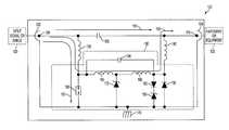
- FIG. 1is a schematic circuit diagram of a DC pass RF coaxial surge protector with a gas tube in accordance with an embodiment of the invention
- FIG. 2is a cross-sectional view of the DC pass RF coaxial surge protector having the schematic circuit diagram shown in FIG. 1 in accordance with an embodiment of the invention
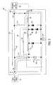
- FIG. 3is a schematic circuit diagram of a DC injector/pick-off and RF pass-through coaxial surge protector with a gas tube in accordance with an embodiment of the invention.
- FIG. 4is a cross-sectional view of the DC injector/pick-off and RF pass-through coaxial surge protector having the schematic circuit diagram shown in FIG. 3 in accordance with an embodiment of the invention.
- FIG. 1a schematic circuit diagram of a DC pass RF coaxial surge protector 100 is shown.
- the surge protector 100protects hardware or equipment 125 connected to the surge protector 100 from an electrical surge 120 that could damage or destroy the hardware or equipment 125 .
- the surge protector 100includes a number of different electrical components, such as capacitors, inductors and diodes.
- capacitors, inductors and diodesFor illustrative purposes, the schematic circuit diagram of the surge protector 100 will be described with reference to specific capacitor, inductor or diode values to achieve specific surge protection capabilities. However, other specific capacitor, inductor or diode values or configurations may be used to achieve other electrical or surge protection characteristics.
- the frequency range of operation for the surge protector 100 described by the schematic circuit diagramis between about 680 MHz and about 2.5 GHz.
- the frequency range of operationis 680 MHz to 1.0 GHz, within which the insertion loss is specified less than 0.1 dB and the voltage standing wave ratio (VSWR) is specified less than 1.1:1.
- the frequency range of operationis 1.0 MHz to 3.0 MHz (a telemetry band), within which the insertion loss is specified less than 0.4 dB and the VSWR is specified less than 1.4:1.
- the values produced abovecan vary depending on the frequency range, degree of surge protection and RF performance desired.
- the surge protector 100has two connection terminals including an input port 102 having an input center conductor 109 and an output port 104 having an output center conductor 110 .
- the connection at the input port 102 and the output port 104may be a center conductor such as a coaxial line with center pins as the input center conductor 109 and the output center conductor 110 for propagating DC currents and RF signals and an outer shield that surrounds the center pins.
- the input port 102may function as an output port and the output port 104 may function as an input port.
- the protected hardware or equipment 125can be any communications equipment, cell tower, base station, PC computer, server, network component or equipment, network connector or any other type of surge sensitive electronic equipment.
- the surge protector 100has various components coupled between the input center conductor 109 and the output center conductor 110 , the components structured to form a desired impedance (e.g., 50 ⁇ ) and for providing various signal paths through the surge protector 100 .
- These signal pathsinclude an RF path 155 , a DC path 160 and a main surge path 165 .
- the RF path 155includes the input center conductor 109 , a DC blocking capacitor 130 and the output center conductor 110 .
- RF signalstravel across the RF path 155 to the hardware or equipment 125 .
- the protected hardware or equipment 125can receive or transmit RF signals along the RF path 155 , thus the surge protector 100 can operate in a bidirectional RF manner. In the preferred embodiment, better surge performance is exhibited when operating in a unidirectional manner from the input port 102 to the output port 104 .
- the capacitor 130is placed in series with the input center conductor 109 and the output center conductor 110 in order to block DC signals and undesirable surge transients.
- the capacitor 130has a value between about 3 picoFarads (pF) and about 15 pF wherein higher capacitance values allow for better low frequency performance.
- the capacitor 130has a value of about 4.5 pF.
- the capacitor 130is a capacitive device realized in either lumped or distributed form. Alternatively, the capacitor 130 can be realized by parallel rods, coupling devices, conductive plates or any other device or combination of elements which produce a capacitive effect.
- the capacitance of the capacitor 130can vary depending upon the frequency of operation desired and the capacitor 130 will block the flow of DC signals while permitting the flow of AC signals depending on this chosen capacitance and frequency. At certain frequencies, the capacitor 130 may operate to attenuate the AC signal.
- the DC path 160includes the input center conductor 109 , a first spiral coil or inductor 135 , a second spiral coil or inductor 140 , intermediate coils or inductors 145 and 150 and the output center conductor 110 .
- a DC signal on the input center conductor 109travels outside of the RF path 155 and around the blocking capacitor 130 by propagating along the first spiral inductor 135 , along the intermediate inductors 145 and 150 and along the second spiral inductor 140 where the DC signal travels to the output center conductor 110 .
- the main surge path 165provides a path for the surge 120 to travel and dissipate to ground instead of propagating through to the connected hardware or equipment 125 .
- Several electrical components 195are additionally coupled between the input center conductor 109 and the output center conductor 110 for helping to mitigate the electrical surge 120 that may be present at the input port 102 of the surge protector 100 .
- the electrical components 195are mounted or integrated with a printed circuit board or a common ground base plate, the printed circuit board or base plate positioned within the surge protector 100 as described in greater detail in FIG. 2 .
- the electrical components 195include a gas tube 105 , the intermediate inductors 145 and 150 , a capacitor 148 , zener diodes 175 and 185 and diodes 180 and 190 .
- the gas tube 105 and the diode componentsare coupled between a common ground 170 (e.g., a housing of the surge protector 100 ) and a node at some location along the DC path 160 .
- a common ground 170e.g., a housing of the surge protector 100
- the surge 120is blocked by the blocking capacitor 130 and is routed through the first spiral inductor 135 .
- the surge 120flows along the main surge path 165 from the input center conductor 109 , along the first spiral inductor 135 and across the gas tube 105 .
- Auxiliary surge pathsexist through the diode components ( 175 , 185 , 180 and 190 ) to the ground 170 (e.g., a housing of the surge protector 100 ), as discussed in greater detail herein.
- the gas tube 105contains hermetically sealed electrodes that ionize gas during use. When the gas is ionized, the gas tube 105 becomes conductive and the breakdown voltage is lowered. The breakdown voltage varies and is dependent upon the rise time of the surge 120 . Therefore, depending on the characteristics of the surge 120 , several microseconds may elapse before the gas tube 105 becomes ionized and hence conductive. Thus, the leading portion of the surge 120 passes to the intermediate inductors 145 and 150 instead of passing through the gas tube 105 .
- the capacitor 148 connected in parallel across the intermediate inductors 145 and 150is used as a low frequency bypass capacitor for the tuning of telemetry signals.
- the intermediate inductors 145 and 150act as shorts and allows voltages and/or currents to flow unimpeded to the other components.
- the inductors 145 and 150will impede currents and develop a voltage drop, effectively enabling auxiliary surge paths to the ground 170 through the diode components at varying turn-on voltages and turn-on times and delaying the surge currents to allow the gas tube 105 time to trigger.
- one or more of the diodesdivert the portion of the surge 120 to the ground 170 rather than allowing the surge 120 to propagate to the output center conductor 110 .
- These auxiliary surge pathsoperate to dissipate the surge 120 until the gas tube 105 becomes conductive and allows the surge 120 to flow to the ground 170 via the main surge path 165 .
- the zener diodes 175 and 185 and the diodes 180 and 190have faster turn-on times and lower turn-on voltages compared to the gas tube 105 .
- the diode components 180 , 185 and 190are configured for a specific turn-on voltage (e.g., 40 volts) and will conduct to the ground 170 first.
- the zener diode 175is configured to have a higher turn-on voltage (e.g., 80-90 volts) than the diode components 180 , 185 and 190 and will conduct to the ground 170 at some point in time afterwards.
- the gas tube 105is configured to have an even higher turn-on voltage (e.g., 300 volts) and will conduct to the ground 170 last.
- the gas tube 105 or the diode componentsmay be replaced or supplemented with a different non-linear element or surge protection element or device for dissipating the surge 120 to the ground 170 along the main surge path 165 .
- a metal oxide varistor (MOV), diode or any combination thereofmay be incorporated. If the voltage at the MOV is below its clamping or switching voltage, the MOV exhibits a high resistance. If the voltage at the MOV is above its clamping or switching voltage, the MOV exhibits a low resistance.
- MOVscan effectively provide surge protection and are sometimes referred to as non-linear resistors due to their nonlinear current-voltage relationship.
- the gas tube 105is coupled at a first end to the first inductor 135 and at a second end to the common ground 170 .
- the gas tube 105has a capacitance value of about 2 pF and a turn-on voltage of between about 90 volts and about 360 volts.
- the selection of the turn-on voltage for the gas tube 105is a function of the RF power of the surge protector 100 .
- a turn-on voltage of 360 voltswill result in an RF power handling capacity of about 5,000 watts.
- the high RF impedance provided by the first and second spiral inductors 135 and 140allow for higher RF power to travel in the RF path 155 without turning on the gas tube 105 .
- changing the gas tube 105 to have a different turn-on voltageaffects the RF power limitations but does not affect the RF frequency range or tuning of the surge protector 100 .
- the gas tube 105is isolated from (i.e. is not directly connected to) the input center conductor 109 by the first spiral inductor 135 .
- the gas tube 105is isolated from the output center conductor 110 by the second spiral inductor 140 and the intermediate inductors 145 and 150 .
- the first and second spiral inductors 135 and 140provide RF isolation from the gas tube 105 and other components that are known to create passive inter-modulation (PIM).
- PIMpassive inter-modulation
- the incorporation of an RF high impedance elemente.g., an inductor, a quarter-wave stub, etc
- first and second spiral inductors 135 and 140prevent the gas tube 105 and other surge mitigation components from being directly connected to the RF path 155 .
- the first and second spiral inductors 135 and 140may thus be replaced with quarter-wave stubs or other RF high impedance elements to achieve a similar purpose.
- the surge protector 100has a first housing 205 that defines a first cavity 210 .
- the first cavity 210is preferably formed in the shape of a cylinder and has an inner radius of approximately 432.5 mils. In an alternative embodiment, the first cavity 210 can be formed in any shape and of varying sizes.
- the input center conductor 109 and the output center conductor 110are positioned concentric with and located within the first cavity 210 of the first housing 205 .
- the surge protector 100has a second housing 215 that extends from the first housing 205 .
- the first housing 205 and the second housing 215may be formed as a single housing.
- the second housing 215defines a second cavity 220 for housing the electrical components 195 (see FIG. 1 ).
- the input center conductor 109 , the first spiral inductor 135 , the capacitor 130 , the second spiral inductor 140 and the output center conductor 110are positioned within the first cavity 210 of the first housing 205 .
- the input and output center conductors 109 and 110are positioned along a central axis within this first cavity 210 .
- the first inductor 135is positioned along a first plane and the second inductor 140 is positioned along a second plane, the first plane being positioned substantially parallel to the second plane.
- the central axis of the input and output center conductors 109 and 110is positioned substantially perpendicular to the first plane and the second plane.
- the first and second spiral inductors 135 and 140have small foot print designs and may be formed with flat or planar geometries.
- the first and second spiral inductors 135 and 140have values of between about 10 nanoHenries (nH) and about 25 nH with a preferred range of about 17 to 20 nH, as measured at around 100 MHz.
- the chosen values for the first and second spiral inductors 135 and 140help determine the specific RF frequency ranges of operation for the surge protector 100 .
- the diameter, surface area, thickness and shape of the first and second spiral inductors 135 and 140can be varied to adjust the operating frequencies and current handling capabilities of the surge protector 100 .
- an iterative processmay be used to determine the diameter, surface area, thickness and shape of the first and second spiral inductors 135 and 140 to meet the requirements of a particular application.
- the diameter of the first and second spiral inductors 135 and 140 of the surge protector 100is about 0.865 inches and the thickness of the first and second spiral inductors 135 and 140 is about 0.062 inches.
- the spiral inductors 135 and 140spiral in an outward direction.
- the material composition of the first and second spiral inductors 135 and 140helps determine the amount of charge that can be safely dissipated across the first and second spiral inductors 135 and 140 .
- a high tensile strength materialallows the first and second spiral inductors 135 and 140 to discharge or divert a greater amount of current.
- the first and second spiral inductors 135 and 140are made of a 7075-T6 Aluminum material.
- any material having sufficient tensile strength and conductivity for a given applicationmay be used to manufacture the first and second spiral inductors 135 and 140 .
- Each of the components or the housingmay be plated with a silver material or a tri-metal flash plating. This reduces or eliminates the number of dissimilar or different types of metal connections or components in the RF path to improve PIM performance.
- the first and second spiral inductors 135 and 140are positioned within the first cavity 210 .
- Each of the first and second spiral inductors 135 and 140has an inner edge with an inner radius of approximately 62.5 mils and an outer edge with an outer radius of approximately 432.5 mils.
- the inner edge of the first spiral inductor 135is coupled to the input center conductor 109 and the inner edge of the second spiral inductor 140 is coupled to the output center conductor 110 .
- the outer edge of the first spiral inductor 135is coupled to the gas tube 105 .
- the outer edge of the second spiral inductor 140is coupled to the gas tube 105 through various electrical components 195 .
- the first housing 205may operate as a common ground connection to facilitate an easily accessible grounding location for the various surge mitigation elements (e.g., 105 , 175 , 185 and 190 ).
- Each spiral of the first and second spiral inductors 135 and 140spirals in an outward direction.
- each of the first and second spiral inductors 135 and 140has three spirals.
- the number of spirals and thickness of each spiralcan be varied depending on the requirements of a particular application.
- the spirals of the first and second spiral inductors 135 and 140may be of a particular known type such as the Archimedes, Logarithmic, Hyperbolic or any combination of these or other spiral types.
- the surge 120(see FIG. 1 ) first reaches the inner edge of the first spiral inductor 135 .
- the surge 120then travels through the spirals of the first spiral inductor 135 in an outward direction from the inner edge to the outer edge.
- the surge 120is dissipated to ground through one or more of the following elements: the gas tube 105 , the zener diodes 175 and 185 , and/or the diodes 180 and 190 (see FIG. 1 ).
- the main portion of the surge 120is passed across the gas tube 105 (see FIG. 1 ) while auxiliary portions of the surge 120 that are not diverted by the gas tube 105 are diverted to ground by the zener diodes 175 and 185 and/or the diodes 180 and 190 .
- the electrical components 195are mounted or integrated with a printed circuit board or a common ground base plate that is positioned within the second cavity 220 of the second housing 215 and attached to the first housing 205 or the second housing 215 with screws or other fasteners.
- the electrical components 195are thus positioned within the second cavity 220 of the second housing 215 and therefore isolated from the components along the RF path 155 , which are positioned within the first cavity 210 of the first housing 205 .
- DC signalsare moved out of the first cavity 210 and into the second cavity 220 via the first spiral inductor 135 .
- DC signalsare moved back into the first cavity 210 from the second cavity 220 via the second spiral inductor 140 .
- the second cavity 220 or second housing 215may not be needed and the DC path 160 or the main surge path 165 can rather be routed to any location outside of the first cavity 210 of the first housing 205 in order to isolate them from the RF path 155 traveling within the first cavity 210 .
- one or more feed-throughs or passageways 225are used to electrically connect elements or components in the first cavity 210 with elements or components within the second cavity 220 .
- the feed-throughs or passageways 225allow electrical wires or other conductive elements to pass signals from the first cavity 210 to the second cavity 220 and vice versa.
- a first electrical wirepasses through one feed-through or passageway 225 to connect the outer edge of the first spiral inductor 135 to the gas tube 105 and a second electrical wire passes through a different feed-through or passageway 225 to connect the outer edge of the second spiral inductor 140 to the intermediate inductor 150 , the diodes 180 or 190 or the capacitor 148 .
- feed-throughs or passageways 225may be used. Such a configuration allows RF signals to travel along the RF path 155 in the first cavity 210 free from interference due to the surge mitigation circuitry located in the second cavity 220 .
- FIG. 3a schematic circuit diagram of a DC injector/pick-off and RF pass-through coaxial surge protector 300 is shown.
- the surge protector 300operates to protect the hardware or equipment 125 from electrical surges in a similar fashion to the surge protector 100 described for FIG. 1 and includes an input port 302 having an input center conductor 309 and an output port 304 having an output center conductor 310 .
- the connection at the input port 302 and the output port 304may be a center conductor such as a coaxial line with center pins as the input center conductor 309 and the output center conductor 310 for propagating DC currents and RF signals and an outer shield that surrounds the center pins.
- the surge protector 300utilizes many of the same electrical components as the surge protector 100 , including the blocking capacitor 130 , the first and second spiral inductors 135 and 140 , the gas tube 105 , the intermediate inductors 145 and 150 , the capacitor 148 , the zener diodes 175 and 185 and the diodes 180 and 190 . Certain components are electrically connected in a different manner to create signal paths that differ from those of the surge protector 100 described in FIG. 1 , as discussed in greater detail herein.
- the surge protector 300includes an RF path 355 that comprises the input center conductor 309 , the capacitor 130 and the output center conductor 310 .
- the RF path 355operates similar to the RF path 155 described in FIG. 1 .
- the surge protector 300also includes a main surge path 365 for enabling the surge 120 present at the input center conductor 309 to travel and dissipate to the ground 370 instead of propagating through the surge protector 300 and to the connected hardware or equipment 125 .
- the main surge path 365is similar to the main surge path 165 described above for FIG. 1 .
- the surge protector 300utilizes a different DC path 360 that does not include the second spiral inductor 140 , but rather incorporates an output inductor 398 connected to the intermediate inductor 150 .
- the DC path 360thus includes the input center conductor 309 , the first spiral inductor 135 , the intermediate inductors 145 and 150 , the output inductor 398 and a feed-through connector 399 .
- the feed-through connector 399enables a DC connection to the hardware or equipment 125 .
- the DC path 360is not coupled back with the RF path 355 for output, but rather remains isolated from the RF path 355 .
- the second spiral inductor 140is not connected to the intermediate inductor 150 , the diodes 180 or 190 or the capacitor 148 as in FIG. 1 , but rather is connected between the output center conductor 310 and the ground 370 . Such a connection enables DC signals or surges present at the output center conductor 310 to propagate to the ground 370 through the second spiral inductor 140 .
- FIG. 4is a cross-sectional view of the DC injector/pick-off and RF pass-through coaxial surge protector 300 having the schematic circuit diagram shown in FIG. 3 .
- the surge protector 300is similar to the surge protector 100 described for FIG. 2 and incorporates many of the same electrical components. Thus, many of the sizing, geometry, orientation, material or other aspects of the surge protector 100 or its electrical component parts described above are applicable to the surge protector 300 .
- the surge protector 300has a first housing 405 that defines a first cavity 410 .
- the input center conductor 309 and output center conductor 310are positioned concentric with and located within the first cavity 410 of the first housing 405 .
- the surge protector 300has a second housing 415 that extends from the first housing 405 .
- the first housing 405 and the second housing 415may be formed as a single housing.
- the second housing 415defines a second cavity 420 for housing the electrical components 395 (see FIG. 3 ). In contrast to the surge protector 100 described for FIG. 2 , the second housing 415 extends further outward or away from the first housing 405 .
- the input center conductor 309 , the first spiral inductor 135 , the capacitor 130 , the second spiral inductor 140 and the output center conductor 310are positioned within the first cavity 410 of the first housing 405 .
- the input and output center conductors 309 and 310are positioned along a central axis within this first cavity 410 .
- the first spiral inductor 135is positioned along a first plane and the second spiral inductor 140 is positioned along a second plane, the first plane being substantially parallel to the second plane.
- the central axis of the input and output center conductors 309 and 310is positioned substantially perpendicular to the first plane and the second plane.
- the first and second spiral inductors 135 and 140are designed, composed or positioned with similar configurations or materials as described above for FIG. 2 .
- the surge 120first reaches the inner edge or radius of the first spiral inductor 135 and travels in an outward direction through the spirals of the first spiral inductor 135 to the outer edge or radius of the first spiral inductor 135 .
- the surge 120is dissipated to ground (e.g., the housing 405 ) through one or more of the gas tube 105 , the zener diodes 175 and 185 , and/or the diodes 180 and 190 .
- the electrical components 395are mounted or integrated with a printed circuit board or a common ground base plate that is positioned within the second cavity 420 of the second housing 415 and attached to the first housing 405 or the second housing 415 with screws or other fasteners.
- the electrical components 395are therefore isolated from the components along the RF path 355 , which are positioned within the first cavity 410 .
- DC signalsare moved out of the first cavity 410 and into the second cavity 420 via the first spiral inductor 135 .
- one or more feed-throughs or passageways 425are utilized for allowing electrical wires or other conductive elements to pass signals from the first cavity 410 to the second cavity 420 and vice versa.
- the surge protector 100utilizes a plurality of feed-throughs or passageways 225 (see FIG. 2 ), only one feed-through 425 is used by the surge protector 300 .
- no second housing or second cavitymay be needed in an alternative embodiment, rather the electrical components 395 , the DC path 360 or the main surge path 365 may be positioned outside the first cavity 410 of the first housing 405 without being contained within a second cavity or a second housing.
Landscapes
- Emergency Protection Circuit Devices (AREA)
Abstract
Description
Claims (20)
Priority Applications (1)
| Application Number | Priority Date | Filing Date | Title |
|---|---|---|---|
| US13/105,430US8730640B2 (en) | 2010-05-11 | 2011-05-11 | DC pass RF protector having a surge suppression module |
Applications Claiming Priority (2)
| Application Number | Priority Date | Filing Date | Title |
|---|---|---|---|
| US33363510P | 2010-05-11 | 2010-05-11 | |
| US13/105,430US8730640B2 (en) | 2010-05-11 | 2011-05-11 | DC pass RF protector having a surge suppression module |
Publications (2)
| Publication Number | Publication Date |
|---|---|
| US20110279943A1 US20110279943A1 (en) | 2011-11-17 |
| US8730640B2true US8730640B2 (en) | 2014-05-20 |
Family
ID=44911590
Family Applications (1)
| Application Number | Title | Priority Date | Filing Date |
|---|---|---|---|
| US13/105,430Expired - Fee RelatedUS8730640B2 (en) | 2010-05-11 | 2011-05-11 | DC pass RF protector having a surge suppression module |
Country Status (6)
| Country | Link |
|---|---|
| US (1) | US8730640B2 (en) |
| EP (1) | EP2569839B1 (en) |
| AU (1) | AU2011253103B2 (en) |
| CA (1) | CA2798891C (en) |
| WO (1) | WO2011143320A2 (en) |
| ZA (1) | ZA201208345B (en) |
Cited By (3)
| Publication number | Priority date | Publication date | Assignee | Title |
|---|---|---|---|---|
| US10461731B2 (en)* | 2016-09-30 | 2019-10-29 | Ulvac, Inc. | Power supply device |
| US10791656B1 (en)* | 2019-11-01 | 2020-09-29 | Advanced Fusion Systems Llc | Method and device for separating high level electromagnetic disturbances from microwave signals |
| US20210242664A1 (en)* | 2020-02-03 | 2021-08-05 | Ppc Broadband, Inc. | Lightning protection spark gaps for cable devices |
Families Citing this family (19)
| Publication number | Priority date | Publication date | Assignee | Title |
|---|---|---|---|---|
| US9054514B2 (en) | 2012-02-10 | 2015-06-09 | Transtector Systems, Inc. | Reduced let through voltage transient protection or suppression circuit |
| US9048662B2 (en)* | 2012-03-19 | 2015-06-02 | Transtector Systems, Inc. | DC power surge protector |
| US9190837B2 (en) | 2012-05-03 | 2015-11-17 | Transtector Systems, Inc. | Rigid flex electromagnetic pulse protection device |
| US9124093B2 (en) | 2012-09-21 | 2015-09-01 | Transtector Systems, Inc. | Rail surge voltage protector with fail disconnect |
| US8879223B2 (en)* | 2013-01-15 | 2014-11-04 | Silergy Semiconductor Technology (Hangzhou) Ltd | Integrated EMI filter circuit with ESD protection and incorporating capacitors |
| US9356796B2 (en)* | 2013-04-23 | 2016-05-31 | Times Fiber Communications, Inc. | MoCA gateway splitter |
| CN104244311B (en)* | 2013-06-09 | 2017-09-15 | 中国移动通信集团公司 | The passive intermodulation testing method and device of antenna-feedback system |
| KR20170016340A (en) | 2014-05-29 | 2017-02-13 | 톰슨 라이센싱 | A surge protector for a transceiver |
| US9666958B2 (en)* | 2014-12-08 | 2017-05-30 | Commscope Technologies Llc | Capacitively coupled connector junctions having parallel signal paths and related connectors and methods |
| WO2016200700A1 (en) | 2015-06-09 | 2016-12-15 | Transtector Systems, Inc. | Sealed enclosure for protecting electronics |
| US10356928B2 (en) | 2015-07-24 | 2019-07-16 | Transtector Systems, Inc. | Modular protection cabinet with flexible backplane |
| US10588236B2 (en) | 2015-07-24 | 2020-03-10 | Transtector Systems, Inc. | Modular protection cabinet with flexible backplane |
| US9924609B2 (en) | 2015-07-24 | 2018-03-20 | Transtector Systems, Inc. | Modular protection cabinet with flexible backplane |
| US10193335B2 (en) | 2015-10-27 | 2019-01-29 | Transtector Systems, Inc. | Radio frequency surge protector with matched piston-cylinder cavity shape |
| US20180048145A1 (en)* | 2016-08-12 | 2018-02-15 | Hamilton Sundstrand Corporation | Transient voltage protection circuits |
| US9991697B1 (en) | 2016-12-06 | 2018-06-05 | Transtector Systems, Inc. | Fail open or fail short surge protector |
| EP3340409B1 (en)* | 2016-12-23 | 2019-08-14 | ABB Schweiz AG | Inductive element protection in a power supply system |
| FR3092944A1 (en)* | 2019-02-15 | 2020-08-21 | Schneider Electric Industries Sas | Radiofrequency transmission line, device comprising such a transmission line and a system for monitoring an installation comprising such a device |
| CN110444948A (en)* | 2019-08-16 | 2019-11-12 | 四川赛尔特科技有限公司 | A kind of wall-penetrating type antenna feeder Surge Protector |
Citations (130)
| Publication number | Priority date | Publication date | Assignee | Title |
|---|---|---|---|---|
| US2030179A (en) | 1933-01-19 | 1936-02-11 | American Telephone & Telegraph | Electrical circuit arrangement |
| US3167729A (en) | 1962-10-29 | 1965-01-26 | Sylvania Electric Prod | Microwave filter insertable within outer wall of coaxial line |
| US3323083A (en) | 1965-03-17 | 1967-05-30 | Amp Inc | Means and method for transmission line compensation |
| US3619721A (en) | 1970-06-01 | 1971-11-09 | Gen Electric | Triggered vacuum gap keep-alive circuit |
| US3663901A (en) | 1970-02-27 | 1972-05-16 | Amp Inc | Tuned coaxial device |
| US3731234A (en) | 1971-12-27 | 1973-05-01 | Bell Telephone Labor Inc | Combined voice frequency transmission and dc signaling circuit |
| US3750053A (en) | 1972-04-24 | 1973-07-31 | Plessey Inc | Coaxial transmission line rf switch |
| US3783178A (en) | 1972-08-03 | 1974-01-01 | Gen Signal Corp | Expansion joint for connecting rigid conduit with grounding continuity |
| US3831110A (en) | 1972-05-01 | 1974-08-20 | Cornell Res Foundation Inc | Multi-axis cavities for microwave semiconductors |
| US3845358A (en) | 1973-06-29 | 1974-10-29 | Gen Electric | Integrated polycrystalline varistor surge protective device for high frequency applications |
| US3944937A (en) | 1973-12-06 | 1976-03-16 | Matsushita Electric Industrial Co., Ltd. | Broad-band signal transmitting device using transformer |
| US3980976A (en) | 1974-03-28 | 1976-09-14 | Sony Corporation | Coaxial connector |
| US4047120A (en) | 1976-07-15 | 1977-09-06 | The United States Of America As Represented By The Secretary Of The Navy | Transient suppression circuit for push-pull switching amplifiers |
| US4046451A (en) | 1976-07-08 | 1977-09-06 | Andrew Corporation | Connector for coaxial cable with annularly corrugated outer conductor |
| US4112395A (en) | 1977-06-10 | 1978-09-05 | Cincinnati Electronics Corp. | Method of and apparatus for matching a load circuit to a drive circuit |
| US4262317A (en) | 1979-03-22 | 1981-04-14 | Reliable Electric Company | Line protector for a communications circuit |
| US4356360A (en) | 1981-02-26 | 1982-10-26 | Amf Incorporated | Pull-to-turn switch |
| US4359764A (en) | 1980-04-08 | 1982-11-16 | Block Roger R | Connector for electromagnetic impulse suppression |
| US4384331A (en) | 1979-04-23 | 1983-05-17 | Nissan Motor Company, Limited | Noise suppressor for vehicle digital system |
| US4409637A (en) | 1980-04-08 | 1983-10-11 | Block Roger R | Connector for electromagnetic impulse suppression |
| US4481641A (en) | 1982-09-30 | 1984-11-06 | Ford Motor Company | Coaxial cable tap coupler for a data transceiver |
| US4554608A (en) | 1982-11-15 | 1985-11-19 | Block Roger R | Connector for electromagnetic impulse suppression |
| US4563720A (en) | 1984-04-17 | 1986-01-07 | General Semiconductor Industries, Inc. | Hybrid AC line transient suppressor |
| US4586104A (en) | 1983-12-12 | 1986-04-29 | Rit Research Corp. | Passive overvoltage protection devices, especially for protection of computer equipment connected to data lines |
| US4689713A (en) | 1985-06-12 | 1987-08-25 | Les Cables De Lyon | High voltage surge protection for electrical power line |
| US4698721A (en) | 1983-11-07 | 1987-10-06 | Puroflow Corp. | Power line filter for transient and continuous noise suppression |
| US4727350A (en) | 1986-04-28 | 1988-02-23 | Hitoshi Ohkubo | Surge absorber |
| US4952173A (en) | 1986-09-05 | 1990-08-28 | Raychem Pontoise | Circuit protection device |
| CH675933A5 (en) | 1989-07-27 | 1990-11-15 | Huber+Suhner Ag | Triaxial electromagnetic pulse conductor - has inner conductor and two screening conductors with unit to maintain contact with overload conductor |
| US4984146A (en) | 1990-03-27 | 1991-01-08 | International Business Machines Corporation | Suppression of radiated EMI for power supplies |
| US4985800A (en) | 1989-10-30 | 1991-01-15 | Feldman Nathan W | Lighting protection apparatus for RF equipment and the like |
| US5053910A (en) | 1989-10-16 | 1991-10-01 | Perma Power Electronics, Inc. | Surge suppressor for coaxial transmission line |
| US5057964A (en) | 1986-12-17 | 1991-10-15 | Northern Telecom Limited | Surge protector for telecommunications terminals |
| US5102818A (en) | 1989-09-21 | 1992-04-07 | Deutsche Itt Industries Gmbh | Method for the smooth fine classification of varactor diodes |
| US5122921A (en) | 1990-04-26 | 1992-06-16 | Industrial Communication Engineers, Ltd. | Device for electromagnetic static and voltage suppression |
| US5124873A (en) | 1989-10-30 | 1992-06-23 | Efi Corporation | Surge suppression circuit for high frequency communication networks |
| US5142429A (en) | 1990-05-07 | 1992-08-25 | Telefonaktiebolaget L M Ericsson | Overvoltage and overcurrent protective circuit with high earth balance |
| US5166855A (en) | 1991-02-27 | 1992-11-24 | Semitron Industries Ltd. | Surge protector with thermal failsafe |
| US5170151A (en) | 1991-02-21 | 1992-12-08 | Hochstein Peter A | Method and assembly for disconnecting a battery from its operating system |
| US5278720A (en) | 1991-09-20 | 1994-01-11 | Atlantic Scientific Corp. | Printed circuit-mounted surge suppressor matched to characteristic impedance of high frequency transmission line |
| US5321573A (en) | 1992-07-16 | 1994-06-14 | Dale Electronics, Inc. | Monolythic surge suppressor |
| US5353189A (en) | 1992-11-02 | 1994-10-04 | Tomlinson John C | Surge protector for vehicular traffic monitoring equipment |
| US5412526A (en) | 1993-02-10 | 1995-05-02 | Square D Company | Surge arrester circuit and housing therefor |
| US5442330A (en) | 1993-12-27 | 1995-08-15 | Motorola, Inc. | Coupled line filter with improved out-of-band rejection |
| US5537044A (en) | 1994-09-30 | 1996-07-16 | The United States Of America As Represented By The Secretary Of The Navy | Surge voltage generator for pulsing grounded and ungrounded electrical equipment |
| US5611224A (en) | 1993-10-29 | 1997-03-18 | The Eastern Company | Handle operable rotary latch and lock |
| US5617284A (en) | 1994-08-05 | 1997-04-01 | Paradise; Rick | Power surge protection apparatus and method |
| US5625521A (en) | 1994-07-22 | 1997-04-29 | Pacusma Co.,Ltd. | Surge protection circuitry |
| US5667298A (en) | 1996-01-16 | 1997-09-16 | Cedarapids, Inc. | Portable concrete mixer with weigh/surge systems |
| US5721662A (en) | 1992-07-29 | 1998-02-24 | Act Communications, Inc. | Floating ground isolator for a communications cable locating system |
| US5781844A (en) | 1995-03-22 | 1998-07-14 | Scientific-Atlanta, Inc. | Method and apparatus for distributing a power signal and an RF signal |
| US5790361A (en) | 1997-03-31 | 1998-08-04 | The Whitaker Corporation | Coaxial surge protector with impedance matching |
| US5798790A (en) | 1995-09-22 | 1998-08-25 | International Business Machines Corp. | Display apparatus with gamma measurement |
| US5844766A (en) | 1997-09-09 | 1998-12-01 | Forem S.R.L. | Lightning supression system for tower mounted antenna systems |
| US5854730A (en) | 1997-09-15 | 1998-12-29 | Mitchell; Dennis | Transient and voltage surge protection system and method for preventing damage to electrical equipment |
| US5953195A (en) | 1997-02-26 | 1999-09-14 | Reltec Corporation | Coaxial protector |
| US5966283A (en) | 1995-08-18 | 1999-10-12 | Act Communications, Inc. | Surge suppression for radio frequency transmission lines |
| US5982602A (en) | 1993-10-07 | 1999-11-09 | Andrew Corporation | Surge protector connector |
| US5986869A (en) | 1998-02-05 | 1999-11-16 | Polyphaser Corporation | Grounding panel |
| US6054905A (en) | 1998-01-21 | 2000-04-25 | General Instrument Coporation | User configurable CATV power inserter |
| US6060182A (en) | 1997-06-09 | 2000-05-09 | Teikoku Piston Ring Co., Ltd. | Hard coating material, sliding member covered with hard coating material and manufacturing method thereof |
| US6061223A (en) | 1997-10-14 | 2000-05-09 | Polyphaser Corporation | Surge suppressor device |
| US6086544A (en) | 1999-03-31 | 2000-07-11 | Ethicon Endo-Surgery, Inc. | Control apparatus for an automated surgical biopsy device |
| US6137352A (en) | 1997-01-27 | 2000-10-24 | Huber And Suhner Ag | Circuit arrangement for protection of HF-input-circuit on telecommunications devices |
| US6141194A (en) | 1998-09-22 | 2000-10-31 | Simmonds Precision Products, Inc. | Aircraft fuel tank protective barrier and method |
| US6177849B1 (en) | 1998-11-18 | 2001-01-23 | Oneline Ag | Non-saturating, flux cancelling diplex filter for power line communications |
| US6226166B1 (en) | 1997-11-28 | 2001-05-01 | Erico Lighting Technologies Pty Ltd | Transient overvoltage and lightning protection of power connected equipment |
| US6243247B1 (en) | 1998-09-22 | 2001-06-05 | Polyphaser Corporation | Stripline transient protection device |
| US6252755B1 (en) | 1999-08-11 | 2001-06-26 | Advanced Micro Devices, Inc. | Apparatus and method for implementing a home network using customer-premises power lines |
| US6281690B1 (en) | 1996-07-19 | 2001-08-28 | Lockheed Martin Corporation | Coaxial radio frequency test probe |
| US6342998B1 (en) | 1998-11-13 | 2002-01-29 | Leviton Manufacturing Co., Inc. | Data surge protection module |
| US6381283B1 (en) | 1998-10-07 | 2002-04-30 | Controlnet, Inc. | Integrated socket with chip carrier |
| US6385030B1 (en) | 1999-09-02 | 2002-05-07 | Marconi Communications, Inc. | Reduced signal loss surge protection circuit |
| US6394122B1 (en) | 2000-09-21 | 2002-05-28 | Pacific Seismic Products, Inc. | Shock actuated sensor for fluid valve |
| US6421220B2 (en) | 1998-05-29 | 2002-07-16 | Porta Systems Corporation | Low capacitance surge protector for high speed data transmission |
| US20020167302A1 (en) | 2001-05-09 | 2002-11-14 | Gallavan Michael F. | Surge current measurement |
| US20020191360A1 (en) | 2001-05-22 | 2002-12-19 | Enrico Colombo | Current detector for surge arrester diagnostic and overvoltage assessment in high voltage substations |
| US6502599B1 (en) | 2000-09-21 | 2003-01-07 | Pacific Seismic Products, Inc. | Shock actuated responsive mechanism for vertical fluid valve assemblies |
| US6527004B1 (en) | 2000-09-21 | 2003-03-04 | Pacific Seismic Products, Inc. | Shock actuated responsive mechanism for vertical fluid valve assemblies |
| US6535369B1 (en) | 2000-06-16 | 2003-03-18 | Teal Electronics Corporation | Adaptive surge suppressor |
| US20030062967A1 (en)* | 2001-10-03 | 2003-04-03 | Carey Ritchey | Broadband PIN diode attenuator bias network |
| US20030072121A1 (en)* | 2001-10-12 | 2003-04-17 | Polyphaser Corporation | Rf surge protection device |
| US20030211782A1 (en) | 2002-05-07 | 2003-11-13 | Mr. Joseph Lorenzo De Guzman | Filtered RJ11 connector module with LED indicators and method of manufacturing |
| US6650203B2 (en) | 2000-03-21 | 2003-11-18 | Diehl Avionik Gmbh | Filter arrangement |
| US20040042149A1 (en) | 2002-04-15 | 2004-03-04 | Edward Devine | Surge lightning protection device |
| US6721155B2 (en) | 2001-08-23 | 2004-04-13 | Andrew Corp. | Broadband surge protector with stub DC injection |
| US6754060B2 (en) | 2000-07-06 | 2004-06-22 | George M. Kauffman | Protective device |
| US20040121648A1 (en) | 2002-07-26 | 2004-06-24 | V-Squared Networks | Network device for communicating information |
| US6757152B2 (en) | 2001-09-05 | 2004-06-29 | Avx Corporation | Cascade capacitor |
| US20040145849A1 (en) | 2002-11-15 | 2004-07-29 | Chang Byung-Ho | Surge protection device and method |
| US6782329B2 (en) | 1998-02-19 | 2004-08-24 | Square D Company | Detection of arcing faults using bifurcated wiring system |
| US6789560B1 (en) | 2000-09-21 | 2004-09-14 | Pacific Seismic Products, Inc. | Shock actuated responsive mechanism with improved safety means to prevent over-rotation of the valve reset mechanism |
| US6814100B1 (en) | 2000-09-21 | 2004-11-09 | Pacific Seismic Products, Inc. | Shock actuated responsive mechanism with means to enable a remote detecting means to determine that the valve assembly has been closed |
| US6816348B2 (en) | 2001-05-18 | 2004-11-09 | Compal Electronics, Inc. | Input protection circuit of a handheld electric device |
| US20040264087A1 (en) | 2003-06-30 | 2004-12-30 | Bishop Roger S | Transient protector for wireless communications equipment |
| US20050036262A1 (en) | 2003-07-09 | 2005-02-17 | Siebenthall Fred Mac | DC Voltage surge suppressor with distributed capacitance EMI filtering and impedance matching |
| US20050044858A1 (en) | 2003-08-26 | 2005-03-03 | Kenneth Hooker | Two stage solenoid control valve |
| US20050176275A1 (en) | 2004-02-05 | 2005-08-11 | Panamax | Modular signal and power connection device |
| US20050185354A1 (en) | 2004-02-25 | 2005-08-25 | Hoopes Gerald B. | Protection of A/V components |
| US6968852B1 (en) | 2000-09-21 | 2005-11-29 | Pacific Seismic Products, Inc. | Shock actuated responsive mechanism with improved dual safety means to prevent over-rotation of the valve reset mechanism and to provide easy access to the reset knob |
| US6975496B2 (en) | 2002-03-21 | 2005-12-13 | Polyphaser Corporation | Isolated shield coaxial surge suppressor |
| US20060038635A1 (en)* | 2004-08-17 | 2006-02-23 | Dominick Richiuso | Integrated passive filter incorporating inductors and ESD protectors |
| US20060120005A1 (en) | 2004-11-15 | 2006-06-08 | Van Sickle Robert J | Transient voltage surge suppression systems |
| US20060139832A1 (en) | 2004-12-29 | 2006-06-29 | Hewlett-Packard Development Company, L.P. | Common mode surge protection filter |
| US20060146458A1 (en)* | 2005-01-03 | 2006-07-06 | Huberag | Surge suppressor with increased surge current capability |
| US7082022B2 (en) | 2002-05-31 | 2006-07-25 | Polyphaser Corporation | Circuit for diverting surges and transient impulses |
| US7092230B2 (en) | 2002-06-26 | 2006-08-15 | Huber & Suhner Ag | Interference filter and lightning conductor device |
| US7106572B1 (en) | 1999-09-17 | 2006-09-12 | Adee Electronic (Societe A Responsabilite Limitee) | Device for protecting against voltage surges |
| US7130103B2 (en) | 2004-03-08 | 2006-10-31 | Seiko Epson Corporation | Optical modulator and manufacturing method of optical modulator |
| US7159236B2 (en) | 2000-06-30 | 2007-01-02 | Kabushiki Kaisha Toshiba | Transmission/reception integrated radio-frequency apparatus |
| US20070053130A1 (en) | 2005-09-01 | 2007-03-08 | Andrew Corporation | Offset Planar Coil Coaxial Surge Suppressor |
| US20070095400A1 (en) | 2005-11-03 | 2007-05-03 | Parker-Hannifin Corporation | Shut-off valve system |
| US20070097583A1 (en) | 2005-10-31 | 2007-05-03 | Andrew Corporation | Tuned Coil Coaxial Surge Suppressor |
| US20070139850A1 (en) | 2005-12-15 | 2007-06-21 | Raycap Corporation | Overvoltage protection devices including wafer of varistor material |
| US7250829B2 (en) | 2001-09-14 | 2007-07-31 | Matsushita Electric Industrial Co., Ltd. | High frequency switch |
| US7338547B2 (en) | 2003-10-02 | 2008-03-04 | Laird Technologies, Inc. | EMI-absorbing air filter |
| US7371970B2 (en) | 2002-12-06 | 2008-05-13 | Flammer Jeffrey D | Rigid-flex circuit board system |
| US7430103B2 (en) | 2003-09-19 | 2008-09-30 | Sharp Kabushiki Kaisha | Static electricity protective circuit and high-frequency circuit apparatus incorporating the same |
| US7453268B2 (en) | 2005-06-29 | 2008-11-18 | Delphi Technologies, Inc. | Input power protected ratiometric output sensor circuit |
| US7471172B2 (en) | 2003-05-02 | 2008-12-30 | Lgp Allgon Ab | Microwave transmission unit including lightning protection |
| US7507105B1 (en) | 2007-07-17 | 2009-03-24 | Ventek, Llc | Hazardous area coupler device |
| US20090103226A1 (en) | 2007-10-18 | 2009-04-23 | Polyphaser Corporation | Surge suppression device having one or more rings |
| US20090109584A1 (en)* | 2007-10-30 | 2009-04-30 | Polyphaser Corporation | Surge protection circuit for passing dc and rf signals |
| US20090284888A1 (en)* | 2008-05-19 | 2009-11-19 | Polyphaser Corporation | Dc and rf pass broadband surge suppressor |
| US7623332B2 (en)* | 2008-01-31 | 2009-11-24 | Commscope, Inc. Of North Carolina | Low bypass fine arrestor |
| US20090296430A1 (en) | 2008-05-29 | 2009-12-03 | Airbus France | Pre-charging device for a chopping converter, and an assembly and aircraft comprising it |
| US7817398B1 (en) | 2007-11-14 | 2010-10-19 | Sprint Communications Company L.P. | Surge arrestor mounting system |
| US20110080683A1 (en)* | 2009-10-02 | 2011-04-07 | Jones Jonathan L | Rf coaxial surge protectors with non-linear protection devices |
| US7948726B2 (en)* | 2008-09-25 | 2011-05-24 | Panasonic Automotive Systems Company Of America, Division Of Panasonic Corporation Of North America | Electrostatic discharge (ESD) protection circuit and method |
| US20110159727A1 (en) | 2009-12-28 | 2011-06-30 | Matt Howard | Power distribution device |
Family Cites Families (1)
| Publication number | Priority date | Publication date | Assignee | Title |
|---|---|---|---|---|
| KR100900800B1 (en)* | 2007-08-17 | 2009-06-04 | 주식회사 텔콘 | RF surge protector |
- 2011
- 2011-05-11AUAU2011253103Apatent/AU2011253103B2/ennot_activeCeased
- 2011-05-11EPEP11781212.3Apatent/EP2569839B1/ennot_activeNot-in-force
- 2011-05-11USUS13/105,430patent/US8730640B2/ennot_activeExpired - Fee Related
- 2011-05-11CACA2798891Apatent/CA2798891C/ennot_activeExpired - Fee Related
- 2011-05-11WOPCT/US2011/036087patent/WO2011143320A2/enactiveApplication Filing
- 2012
- 2012-11-06ZAZA2012/08345Apatent/ZA201208345B/enunknown
Patent Citations (140)
| Publication number | Priority date | Publication date | Assignee | Title |
|---|---|---|---|---|
| US2030179A (en) | 1933-01-19 | 1936-02-11 | American Telephone & Telegraph | Electrical circuit arrangement |
| US3167729A (en) | 1962-10-29 | 1965-01-26 | Sylvania Electric Prod | Microwave filter insertable within outer wall of coaxial line |
| US3323083A (en) | 1965-03-17 | 1967-05-30 | Amp Inc | Means and method for transmission line compensation |
| US3663901A (en) | 1970-02-27 | 1972-05-16 | Amp Inc | Tuned coaxial device |
| US3619721A (en) | 1970-06-01 | 1971-11-09 | Gen Electric | Triggered vacuum gap keep-alive circuit |
| US3731234A (en) | 1971-12-27 | 1973-05-01 | Bell Telephone Labor Inc | Combined voice frequency transmission and dc signaling circuit |
| US3750053A (en) | 1972-04-24 | 1973-07-31 | Plessey Inc | Coaxial transmission line rf switch |
| US3831110A (en) | 1972-05-01 | 1974-08-20 | Cornell Res Foundation Inc | Multi-axis cavities for microwave semiconductors |
| US3783178A (en) | 1972-08-03 | 1974-01-01 | Gen Signal Corp | Expansion joint for connecting rigid conduit with grounding continuity |
| US3845358A (en) | 1973-06-29 | 1974-10-29 | Gen Electric | Integrated polycrystalline varistor surge protective device for high frequency applications |
| US3944937A (en) | 1973-12-06 | 1976-03-16 | Matsushita Electric Industrial Co., Ltd. | Broad-band signal transmitting device using transformer |
| US3980976A (en) | 1974-03-28 | 1976-09-14 | Sony Corporation | Coaxial connector |
| US4046451A (en) | 1976-07-08 | 1977-09-06 | Andrew Corporation | Connector for coaxial cable with annularly corrugated outer conductor |
| US4047120A (en) | 1976-07-15 | 1977-09-06 | The United States Of America As Represented By The Secretary Of The Navy | Transient suppression circuit for push-pull switching amplifiers |
| US4112395A (en) | 1977-06-10 | 1978-09-05 | Cincinnati Electronics Corp. | Method of and apparatus for matching a load circuit to a drive circuit |
| US4262317A (en) | 1979-03-22 | 1981-04-14 | Reliable Electric Company | Line protector for a communications circuit |
| US4384331A (en) | 1979-04-23 | 1983-05-17 | Nissan Motor Company, Limited | Noise suppressor for vehicle digital system |
| US4409637A (en) | 1980-04-08 | 1983-10-11 | Block Roger R | Connector for electromagnetic impulse suppression |
| US4359764A (en) | 1980-04-08 | 1982-11-16 | Block Roger R | Connector for electromagnetic impulse suppression |
| US4356360A (en) | 1981-02-26 | 1982-10-26 | Amf Incorporated | Pull-to-turn switch |
| US4481641A (en) | 1982-09-30 | 1984-11-06 | Ford Motor Company | Coaxial cable tap coupler for a data transceiver |
| US4554608A (en) | 1982-11-15 | 1985-11-19 | Block Roger R | Connector for electromagnetic impulse suppression |
| US4698721A (en) | 1983-11-07 | 1987-10-06 | Puroflow Corp. | Power line filter for transient and continuous noise suppression |
| US4586104A (en) | 1983-12-12 | 1986-04-29 | Rit Research Corp. | Passive overvoltage protection devices, especially for protection of computer equipment connected to data lines |
| US4563720A (en) | 1984-04-17 | 1986-01-07 | General Semiconductor Industries, Inc. | Hybrid AC line transient suppressor |
| US4689713A (en) | 1985-06-12 | 1987-08-25 | Les Cables De Lyon | High voltage surge protection for electrical power line |
| US4727350A (en) | 1986-04-28 | 1988-02-23 | Hitoshi Ohkubo | Surge absorber |
| US4727350B1 (en) | 1986-04-28 | 1994-02-01 | Ohkubo Hitoshi | Surge absorber |
| US4952173A (en) | 1986-09-05 | 1990-08-28 | Raychem Pontoise | Circuit protection device |
| US5057964A (en) | 1986-12-17 | 1991-10-15 | Northern Telecom Limited | Surge protector for telecommunications terminals |
| CH675933A5 (en) | 1989-07-27 | 1990-11-15 | Huber+Suhner Ag | Triaxial electromagnetic pulse conductor - has inner conductor and two screening conductors with unit to maintain contact with overload conductor |
| US5102818A (en) | 1989-09-21 | 1992-04-07 | Deutsche Itt Industries Gmbh | Method for the smooth fine classification of varactor diodes |
| US5053910A (en) | 1989-10-16 | 1991-10-01 | Perma Power Electronics, Inc. | Surge suppressor for coaxial transmission line |
| US5124873A (en) | 1989-10-30 | 1992-06-23 | Efi Corporation | Surge suppression circuit for high frequency communication networks |
| US4985800A (en) | 1989-10-30 | 1991-01-15 | Feldman Nathan W | Lighting protection apparatus for RF equipment and the like |
| US4984146A (en) | 1990-03-27 | 1991-01-08 | International Business Machines Corporation | Suppression of radiated EMI for power supplies |
| US5122921A (en) | 1990-04-26 | 1992-06-16 | Industrial Communication Engineers, Ltd. | Device for electromagnetic static and voltage suppression |
| US5142429A (en) | 1990-05-07 | 1992-08-25 | Telefonaktiebolaget L M Ericsson | Overvoltage and overcurrent protective circuit with high earth balance |
| US5170151A (en) | 1991-02-21 | 1992-12-08 | Hochstein Peter A | Method and assembly for disconnecting a battery from its operating system |
| US5166855A (en) | 1991-02-27 | 1992-11-24 | Semitron Industries Ltd. | Surge protector with thermal failsafe |
| US5278720A (en) | 1991-09-20 | 1994-01-11 | Atlantic Scientific Corp. | Printed circuit-mounted surge suppressor matched to characteristic impedance of high frequency transmission line |
| US5321573A (en) | 1992-07-16 | 1994-06-14 | Dale Electronics, Inc. | Monolythic surge suppressor |
| US6292344B1 (en) | 1992-07-29 | 2001-09-18 | Act Communications, Inc. | Floating ground isolator for a communications cable locating system |
| US5721662A (en) | 1992-07-29 | 1998-02-24 | Act Communications, Inc. | Floating ground isolator for a communications cable locating system |
| US5353189A (en) | 1992-11-02 | 1994-10-04 | Tomlinson John C | Surge protector for vehicular traffic monitoring equipment |
| US5412526A (en) | 1993-02-10 | 1995-05-02 | Square D Company | Surge arrester circuit and housing therefor |
| US5982602A (en) | 1993-10-07 | 1999-11-09 | Andrew Corporation | Surge protector connector |
| US5611224A (en) | 1993-10-29 | 1997-03-18 | The Eastern Company | Handle operable rotary latch and lock |
| US5442330A (en) | 1993-12-27 | 1995-08-15 | Motorola, Inc. | Coupled line filter with improved out-of-band rejection |
| US5625521A (en) | 1994-07-22 | 1997-04-29 | Pacusma Co.,Ltd. | Surge protection circuitry |
| US5617284A (en) | 1994-08-05 | 1997-04-01 | Paradise; Rick | Power surge protection apparatus and method |
| US5537044A (en) | 1994-09-30 | 1996-07-16 | The United States Of America As Represented By The Secretary Of The Navy | Surge voltage generator for pulsing grounded and ungrounded electrical equipment |
| US5781844A (en) | 1995-03-22 | 1998-07-14 | Scientific-Atlanta, Inc. | Method and apparatus for distributing a power signal and an RF signal |
| US5966283A (en) | 1995-08-18 | 1999-10-12 | Act Communications, Inc. | Surge suppression for radio frequency transmission lines |
| US5798790A (en) | 1995-09-22 | 1998-08-25 | International Business Machines Corp. | Display apparatus with gamma measurement |
| US5667298A (en) | 1996-01-16 | 1997-09-16 | Cedarapids, Inc. | Portable concrete mixer with weigh/surge systems |
| US6281690B1 (en) | 1996-07-19 | 2001-08-28 | Lockheed Martin Corporation | Coaxial radio frequency test probe |
| US6137352A (en) | 1997-01-27 | 2000-10-24 | Huber And Suhner Ag | Circuit arrangement for protection of HF-input-circuit on telecommunications devices |
| US5953195A (en) | 1997-02-26 | 1999-09-14 | Reltec Corporation | Coaxial protector |
| US5790361A (en) | 1997-03-31 | 1998-08-04 | The Whitaker Corporation | Coaxial surge protector with impedance matching |
| US6060182A (en) | 1997-06-09 | 2000-05-09 | Teikoku Piston Ring Co., Ltd. | Hard coating material, sliding member covered with hard coating material and manufacturing method thereof |
| US5844766A (en) | 1997-09-09 | 1998-12-01 | Forem S.R.L. | Lightning supression system for tower mounted antenna systems |
| US5854730A (en) | 1997-09-15 | 1998-12-29 | Mitchell; Dennis | Transient and voltage surge protection system and method for preventing damage to electrical equipment |
| US6061223A (en) | 1997-10-14 | 2000-05-09 | Polyphaser Corporation | Surge suppressor device |
| US6115227A (en) | 1997-10-14 | 2000-09-05 | Polyphaser Corporation | Surge suppressor device |
| US6236551B1 (en) | 1997-10-14 | 2001-05-22 | Polyphaser Corporation | Surge suppressor device |
| US6226166B1 (en) | 1997-11-28 | 2001-05-01 | Erico Lighting Technologies Pty Ltd | Transient overvoltage and lightning protection of power connected equipment |
| US6054905A (en) | 1998-01-21 | 2000-04-25 | General Instrument Coporation | User configurable CATV power inserter |
| US5986869A (en) | 1998-02-05 | 1999-11-16 | Polyphaser Corporation | Grounding panel |
| US6782329B2 (en) | 1998-02-19 | 2004-08-24 | Square D Company | Detection of arcing faults using bifurcated wiring system |
| US6421220B2 (en) | 1998-05-29 | 2002-07-16 | Porta Systems Corporation | Low capacitance surge protector for high speed data transmission |
| US6243247B1 (en) | 1998-09-22 | 2001-06-05 | Polyphaser Corporation | Stripline transient protection device |
| US6141194A (en) | 1998-09-22 | 2000-10-31 | Simmonds Precision Products, Inc. | Aircraft fuel tank protective barrier and method |
| US6381283B1 (en) | 1998-10-07 | 2002-04-30 | Controlnet, Inc. | Integrated socket with chip carrier |
| US6342998B1 (en) | 1998-11-13 | 2002-01-29 | Leviton Manufacturing Co., Inc. | Data surge protection module |
| US6177849B1 (en) | 1998-11-18 | 2001-01-23 | Oneline Ag | Non-saturating, flux cancelling diplex filter for power line communications |
| US6086544A (en) | 1999-03-31 | 2000-07-11 | Ethicon Endo-Surgery, Inc. | Control apparatus for an automated surgical biopsy device |
| US6252755B1 (en) | 1999-08-11 | 2001-06-26 | Advanced Micro Devices, Inc. | Apparatus and method for implementing a home network using customer-premises power lines |
| US6385030B1 (en) | 1999-09-02 | 2002-05-07 | Marconi Communications, Inc. | Reduced signal loss surge protection circuit |
| US7106572B1 (en) | 1999-09-17 | 2006-09-12 | Adee Electronic (Societe A Responsabilite Limitee) | Device for protecting against voltage surges |
| US6650203B2 (en) | 2000-03-21 | 2003-11-18 | Diehl Avionik Gmbh | Filter arrangement |
| US6535369B1 (en) | 2000-06-16 | 2003-03-18 | Teal Electronics Corporation | Adaptive surge suppressor |
| US7159236B2 (en) | 2000-06-30 | 2007-01-02 | Kabushiki Kaisha Toshiba | Transmission/reception integrated radio-frequency apparatus |
| US6754060B2 (en) | 2000-07-06 | 2004-06-22 | George M. Kauffman | Protective device |
| US6394122B1 (en) | 2000-09-21 | 2002-05-28 | Pacific Seismic Products, Inc. | Shock actuated sensor for fluid valve |
| US6527004B1 (en) | 2000-09-21 | 2003-03-04 | Pacific Seismic Products, Inc. | Shock actuated responsive mechanism for vertical fluid valve assemblies |
| US6968852B1 (en) | 2000-09-21 | 2005-11-29 | Pacific Seismic Products, Inc. | Shock actuated responsive mechanism with improved dual safety means to prevent over-rotation of the valve reset mechanism and to provide easy access to the reset knob |
| US6502599B1 (en) | 2000-09-21 | 2003-01-07 | Pacific Seismic Products, Inc. | Shock actuated responsive mechanism for vertical fluid valve assemblies |
| US6814100B1 (en) | 2000-09-21 | 2004-11-09 | Pacific Seismic Products, Inc. | Shock actuated responsive mechanism with means to enable a remote detecting means to determine that the valve assembly has been closed |
| US6789560B1 (en) | 2000-09-21 | 2004-09-14 | Pacific Seismic Products, Inc. | Shock actuated responsive mechanism with improved safety means to prevent over-rotation of the valve reset mechanism |
| US20020167302A1 (en) | 2001-05-09 | 2002-11-14 | Gallavan Michael F. | Surge current measurement |
| US6816348B2 (en) | 2001-05-18 | 2004-11-09 | Compal Electronics, Inc. | Input protection circuit of a handheld electric device |
| US20020191360A1 (en) | 2001-05-22 | 2002-12-19 | Enrico Colombo | Current detector for surge arrester diagnostic and overvoltage assessment in high voltage substations |
| US6721155B2 (en) | 2001-08-23 | 2004-04-13 | Andrew Corp. | Broadband surge protector with stub DC injection |
| US6757152B2 (en) | 2001-09-05 | 2004-06-29 | Avx Corporation | Cascade capacitor |
| US7250829B2 (en) | 2001-09-14 | 2007-07-31 | Matsushita Electric Industrial Co., Ltd. | High frequency switch |
| US20030062967A1 (en)* | 2001-10-03 | 2003-04-03 | Carey Ritchey | Broadband PIN diode attenuator bias network |
| US6785110B2 (en) | 2001-10-12 | 2004-08-31 | Polyphaser Corporation | Rf surge protection device |
| US20030072121A1 (en)* | 2001-10-12 | 2003-04-17 | Polyphaser Corporation | Rf surge protection device |
| US6975496B2 (en) | 2002-03-21 | 2005-12-13 | Polyphaser Corporation | Isolated shield coaxial surge suppressor |
| US20040042149A1 (en) | 2002-04-15 | 2004-03-04 | Edward Devine | Surge lightning protection device |
| US20030211782A1 (en) | 2002-05-07 | 2003-11-13 | Mr. Joseph Lorenzo De Guzman | Filtered RJ11 connector module with LED indicators and method of manufacturing |
| US7082022B2 (en) | 2002-05-31 | 2006-07-25 | Polyphaser Corporation | Circuit for diverting surges and transient impulses |
| US7092230B2 (en) | 2002-06-26 | 2006-08-15 | Huber & Suhner Ag | Interference filter and lightning conductor device |
| US20040121648A1 (en) | 2002-07-26 | 2004-06-24 | V-Squared Networks | Network device for communicating information |
| US7221550B2 (en) | 2002-11-15 | 2007-05-22 | Samsung Electronics Co., Ltd. | Surge protection device and method |
| US20040145849A1 (en) | 2002-11-15 | 2004-07-29 | Chang Byung-Ho | Surge protection device and method |
| US7371970B2 (en) | 2002-12-06 | 2008-05-13 | Flammer Jeffrey D | Rigid-flex circuit board system |
| US7471172B2 (en) | 2003-05-02 | 2008-12-30 | Lgp Allgon Ab | Microwave transmission unit including lightning protection |
| US20040264087A1 (en) | 2003-06-30 | 2004-12-30 | Bishop Roger S | Transient protector for wireless communications equipment |
| US20050036262A1 (en) | 2003-07-09 | 2005-02-17 | Siebenthall Fred Mac | DC Voltage surge suppressor with distributed capacitance EMI filtering and impedance matching |
| US20050044858A1 (en) | 2003-08-26 | 2005-03-03 | Kenneth Hooker | Two stage solenoid control valve |
| US7104282B2 (en) | 2003-08-26 | 2006-09-12 | Honeywell International, Inc. | Two stage solenoid control valve |
| US7430103B2 (en) | 2003-09-19 | 2008-09-30 | Sharp Kabushiki Kaisha | Static electricity protective circuit and high-frequency circuit apparatus incorporating the same |
| US7338547B2 (en) | 2003-10-02 | 2008-03-04 | Laird Technologies, Inc. | EMI-absorbing air filter |
| US20050176275A1 (en) | 2004-02-05 | 2005-08-11 | Panamax | Modular signal and power connection device |
| US20050185354A1 (en) | 2004-02-25 | 2005-08-25 | Hoopes Gerald B. | Protection of A/V components |
| US7130103B2 (en) | 2004-03-08 | 2006-10-31 | Seiko Epson Corporation | Optical modulator and manufacturing method of optical modulator |
| US20060038635A1 (en)* | 2004-08-17 | 2006-02-23 | Dominick Richiuso | Integrated passive filter incorporating inductors and ESD protectors |
| US7808752B2 (en) | 2004-08-17 | 2010-10-05 | Semiconductor Components Industries, Llc | Integrated passive filter incorporating inductors and ESD protectors |
| US20060120005A1 (en) | 2004-11-15 | 2006-06-08 | Van Sickle Robert J | Transient voltage surge suppression systems |
| US20060139832A1 (en) | 2004-12-29 | 2006-06-29 | Hewlett-Packard Development Company, L.P. | Common mode surge protection filter |
| US20060146458A1 (en)* | 2005-01-03 | 2006-07-06 | Huberag | Surge suppressor with increased surge current capability |
| US7453268B2 (en) | 2005-06-29 | 2008-11-18 | Delphi Technologies, Inc. | Input power protected ratiometric output sensor circuit |
| US20070053130A1 (en) | 2005-09-01 | 2007-03-08 | Andrew Corporation | Offset Planar Coil Coaxial Surge Suppressor |
| US20070097583A1 (en) | 2005-10-31 | 2007-05-03 | Andrew Corporation | Tuned Coil Coaxial Surge Suppressor |
| US20070095400A1 (en) | 2005-11-03 | 2007-05-03 | Parker-Hannifin Corporation | Shut-off valve system |
| US20070139850A1 (en) | 2005-12-15 | 2007-06-21 | Raycap Corporation | Overvoltage protection devices including wafer of varistor material |
| US7507105B1 (en) | 2007-07-17 | 2009-03-24 | Ventek, Llc | Hazardous area coupler device |
| US20090103226A1 (en) | 2007-10-18 | 2009-04-23 | Polyphaser Corporation | Surge suppression device having one or more rings |
| US20090109584A1 (en)* | 2007-10-30 | 2009-04-30 | Polyphaser Corporation | Surge protection circuit for passing dc and rf signals |
| US20110141646A1 (en)* | 2007-10-30 | 2011-06-16 | Jones Jonathan L | Surge protection circuit for passing dc and rf signals |
| US7817398B1 (en) | 2007-11-14 | 2010-10-19 | Sprint Communications Company L.P. | Surge arrestor mounting system |
| US7623332B2 (en)* | 2008-01-31 | 2009-11-24 | Commscope, Inc. Of North Carolina | Low bypass fine arrestor |
| US20090284888A1 (en)* | 2008-05-19 | 2009-11-19 | Polyphaser Corporation | Dc and rf pass broadband surge suppressor |
| US20090296430A1 (en) | 2008-05-29 | 2009-12-03 | Airbus France | Pre-charging device for a chopping converter, and an assembly and aircraft comprising it |
| US7948726B2 (en)* | 2008-09-25 | 2011-05-24 | Panasonic Automotive Systems Company Of America, Division Of Panasonic Corporation Of North America | Electrostatic discharge (ESD) protection circuit and method |
| US20110080683A1 (en)* | 2009-10-02 | 2011-04-07 | Jones Jonathan L | Rf coaxial surge protectors with non-linear protection devices |
| US8456791B2 (en)* | 2009-10-02 | 2013-06-04 | Transtector Systems, Inc. | RF coaxial surge protectors with non-linear protection devices |
| US20110159727A1 (en) | 2009-12-28 | 2011-06-30 | Matt Howard | Power distribution device |
Cited By (4)
| Publication number | Priority date | Publication date | Assignee | Title |
|---|---|---|---|---|
| US10461731B2 (en)* | 2016-09-30 | 2019-10-29 | Ulvac, Inc. | Power supply device |
| US10791656B1 (en)* | 2019-11-01 | 2020-09-29 | Advanced Fusion Systems Llc | Method and device for separating high level electromagnetic disturbances from microwave signals |
| US20210242664A1 (en)* | 2020-02-03 | 2021-08-05 | Ppc Broadband, Inc. | Lightning protection spark gaps for cable devices |
| US11527870B2 (en)* | 2020-02-03 | 2022-12-13 | Ppc Broadband, Inc. | Lightning protection spark gaps for cable devices |
Also Published As
| Publication number | Publication date |
|---|---|
| CA2798891C (en) | 2016-04-12 |
| AU2011253103B2 (en) | 2014-05-08 |
| WO2011143320A3 (en) | 2012-02-23 |
| CA2798891A1 (en) | 2011-11-17 |
| US20110279943A1 (en) | 2011-11-17 |
| ZA201208345B (en) | 2013-07-31 |
| EP2569839B1 (en) | 2019-01-09 |
| AU2011253103A1 (en) | 2012-12-06 |
| EP2569839A2 (en) | 2013-03-20 |
| WO2011143320A2 (en) | 2011-11-17 |
| EP2569839A4 (en) | 2014-01-22 |
Similar Documents
| Publication | Publication Date | Title |
|---|---|---|
| US8730640B2 (en) | DC pass RF protector having a surge suppression module | |
| US8456791B2 (en) | RF coaxial surge protectors with non-linear protection devices | |
| US7944670B2 (en) | Surge protection circuit for passing DC and RF signals | |
| US6785110B2 (en) | Rf surge protection device | |
| US6236551B1 (en) | Surge suppressor device | |
| US8553386B2 (en) | Surge suppression device having one or more rings | |
| US8976500B2 (en) | DC block RF coaxial devices | |
| US8599528B2 (en) | DC and RF pass broadband surge suppressor | |
| US20050259376A1 (en) | Circuit for diverting surges and transient impulses | |
| US20220209735A1 (en) | Band antenna emp filter apparatus having hemp protection capability | |
| CN111525527B (en) | Radio frequency signal thunder and lightning electromagnetic pulse protection device | |
| EP2808959B1 (en) | High voltage discharge protection device and radio frequency transmission apparatus using the same | |
| CN111525528B (en) | Radio frequency signal thunder and lightning electromagnetic pulse multistage bidirectional protection device | |
| KR101439893B1 (en) | Pci protector with surge protection using spiral antenna | |
| HK1076545B (en) | Circuit for diverting surges and transient impulses |
Legal Events
| Date | Code | Title | Description |
|---|---|---|---|
| AS | Assignment | Owner name:TRANSTECTOR SYSTEMS, INC., IDAHO Free format text:ASSIGNMENT OF ASSIGNORS INTEREST;ASSIGNORS:PENWELL, CHRIS;BARTEL, KARL C.;REEL/FRAME:026261/0876 Effective date:20110505 | |
| STCF | Information on status: patent grant | Free format text:PATENTED CASE | |
| AS | Assignment | Owner name:ANTARES CAPITAL LP, AS ADMINISTRATIVE AGENT, ILLIN Free format text:SECURITY INTEREST;ASSIGNOR:TRANSTECTOR SYSTEMS, INC.;REEL/FRAME:042191/0680 Effective date:20170501 Owner name:ANTARES CAPITAL LP, AS ADMINISTRATIVE AGENT, ILLIN Free format text:SECURITY INTEREST;ASSIGNOR:TRANSTECTOR SYSTEMS, INC.;REEL/FRAME:042192/0095 Effective date:20170501 | |
| MAFP | Maintenance fee payment | Free format text:PAYMENT OF MAINTENANCE FEE, 4TH YEAR, LARGE ENTITY (ORIGINAL EVENT CODE: M1551) Year of fee payment:4 | |
| AS | Assignment | Owner name:PASTERNACK ENTERPRISES, INC., CALIFORNIA Free format text:MERGER;ASSIGNOR:TRANSTECTOR SYSTEMS, INC.;REEL/FRAME:055432/0880 Effective date:20180319 Owner name:INFINITE ELECTRONICS INTERNATIONAL, INC., CALIFORNIA Free format text:CHANGE OF NAME;ASSIGNOR:PASTERNACK ENTERPRISES, INC.;REEL/FRAME:055437/0581 Effective date:20180319 | |
| AS | Assignment | Owner name:INFINITE ELECTRONICS INTERNATIONAL, INC., CALIFORNIA Free format text:PATENT RELEASE;ASSIGNOR:ANTARES CAPITAL LP, AS ADMINISTRATIVE AGENT;REEL/FRAME:055488/0714 Effective date:20210302 Owner name:INFINITE ELECTRONICS INTERNATIONAL, INC., CALIFORNIA Free format text:PATENT RELEASE 2L;ASSIGNOR:ANTARES CAPITAL LP, AS ADMINISTRATIVE AGENT;REEL/FRAME:055489/0142 Effective date:20210302 Owner name:JEFFERIES FINANCE LLC, NEW YORK Free format text:FIRST LIEN PATENT SECURITY AGREEMENT;ASSIGNOR:INFINITE ELECTRONICS INTERNATIONAL, INC.;REEL/FRAME:055526/0898 Effective date:20210302 Owner name:JEFFERIES FINANCE LLC, NEW YORK Free format text:SECOND LIEN PATENT SECURITY AGREEMENT;ASSIGNOR:INFINITE ELECTRONICS INTERNATIONAL, INC.;REEL/FRAME:055526/0931 Effective date:20210302 | |
| FEPP | Fee payment procedure | Free format text:MAINTENANCE FEE REMINDER MAILED (ORIGINAL EVENT CODE: REM.); ENTITY STATUS OF PATENT OWNER: LARGE ENTITY | |
| LAPS | Lapse for failure to pay maintenance fees | Free format text:PATENT EXPIRED FOR FAILURE TO PAY MAINTENANCE FEES (ORIGINAL EVENT CODE: EXP.); ENTITY STATUS OF PATENT OWNER: LARGE ENTITY | |
| STCH | Information on status: patent discontinuation | Free format text:PATENT EXPIRED DUE TO NONPAYMENT OF MAINTENANCE FEES UNDER 37 CFR 1.362 | |
| FP | Lapsed due to failure to pay maintenance fee | Effective date:20220520 |