US8730637B2 - Surge protection devices that fail as an open circuit - Google Patents
Surge protection devices that fail as an open circuitDownload PDFInfo
- Publication number
- US8730637B2 US8730637B2US13/330,497US201113330497AUS8730637B2US 8730637 B2US8730637 B2US 8730637B2US 201113330497 AUS201113330497 AUS 201113330497AUS 8730637 B2US8730637 B2US 8730637B2
- Authority
- US
- United States
- Prior art keywords
- surge protection
- switch
- signal
- coupled
- surge
- Prior art date
- Legal status (The legal status is an assumption and is not a legal conclusion. Google has not performed a legal analysis and makes no representation as to the accuracy of the status listed.)
- Expired - Fee Related, expires
Links
- 238000000034methodMethods0.000claimsabstractdescription10
- 239000004020conductorSubstances0.000claimsabstractdescription9
- 230000000007visual effectEffects0.000claimsabstractdescription5
- 239000003990capacitorSubstances0.000claimsdescription10
- 230000008859changeEffects0.000claimsdescription8
- 230000004044responseEffects0.000claimsdescription5
- 238000010586diagramMethods0.000description36
- 230000001012protectorEffects0.000description16
- 230000008901benefitEffects0.000description3
- 238000004891communicationMethods0.000description3
- 230000004913activationEffects0.000description1
- 239000000853adhesiveSubstances0.000description1
- 230000001070adhesive effectEffects0.000description1
- 230000005540biological transmissionEffects0.000description1
- LVQDKIWDGQRHTE-UHFFFAOYSA-NcyromazineChemical compoundNC1=NC(N)=NC(NC2CC2)=N1LVQDKIWDGQRHTE-UHFFFAOYSA-N0.000description1
- 238000005516engineering processMethods0.000description1
- 230000007613environmental effectEffects0.000description1
- 230000001747exhibiting effectEffects0.000description1
- 229910044991metal oxideInorganic materials0.000description1
- 150000004706metal oxidesChemical class0.000description1
- 230000004048modificationEffects0.000description1
- 238000012986modificationMethods0.000description1
- 230000002265preventionEffects0.000description1
- 230000008439repair processEffects0.000description1
- 230000000087stabilizing effectEffects0.000description1
- 230000001629suppressionEffects0.000description1
Images


Classifications
- H—ELECTRICITY
- H02—GENERATION; CONVERSION OR DISTRIBUTION OF ELECTRIC POWER
- H02H—EMERGENCY PROTECTIVE CIRCUIT ARRANGEMENTS
- H02H9/00—Emergency protective circuit arrangements for limiting excess current or voltage without disconnection
- H02H9/04—Emergency protective circuit arrangements for limiting excess current or voltage without disconnection responsive to excess voltage
- H02H9/042—Emergency protective circuit arrangements for limiting excess current or voltage without disconnection responsive to excess voltage comprising means to limit the absorbed power or indicate damaged over-voltage protection device
- H—ELECTRICITY
- H02—GENERATION; CONVERSION OR DISTRIBUTION OF ELECTRIC POWER
- H02H—EMERGENCY PROTECTIVE CIRCUIT ARRANGEMENTS
- H02H3/00—Emergency protective circuit arrangements for automatic disconnection directly responsive to an undesired change from normal electric working condition with or without subsequent reconnection ; integrated protection
- H02H3/02—Details
- H02H3/04—Details with warning or supervision in addition to disconnection, e.g. for indicating that protective apparatus has functioned
- H02H3/048—Checking overvoltage diverters
Definitions
- the present inventiongenerally relates to surge protectors and improvements thereof. More particularly, the present invention relates to surge protectors capable of consistent fail open functionality and improvements thereof.
- Communications equipment, computers, home stereo amplifiers, televisions and other electronic devicesare increasingly manufactured using a variety of electronic components that are vulnerable to damage from electrical energy surges.
- Surge variations in power and transmission line voltages, as well as noise,can change the operating frequency range of connected equipment and severely damage or destroy electronic devices.
- Electronic devices impacted by these surge conditionscan be very expensive to repair or replace. Therefore, a cost effective way to protect these devices and components from power surges is needed.
- a diode protection scheme utilized for a communication systemmay fail as a short at one surge current, but fail open under alternative surge or environmental conditions.
- Gas tubes, metal oxide varistors (MOVs), diodes, sidactors and other voltage or current limiting devicescan similarly exhibit differing failure modes depending upon the environment, system and/or exposure to particular surge currents or voltages.
- Fusesexhibiting a predictable open failure state, have been implemented as safety components in communication or other electronic systems.
- a fuseis a device that will fail open once it has been exposed to high enough current over a given period of time.
- fusesare not very accurate with respect to performance under short surge duration events.
- fuseshave extreme performance variations over temperature. For example, a fuse in ⁇ 40 degree Celsius temperature will take a relatively long time period to fail in the open state. Thus, fuses represent a less than ideal solution for surge protection or suppression despite their heightened failure state predictability.
- circuit breakers and ground fault interrupt (GFI) circuitsare other examples of devices that fail with a predictable open state.
- circuit breakersare slow in reaction and tend to let through the majority of surge currents present.
- GFI circuitslook for differential current flow through the circuit wires and do not activate if the surge currents flow through both of the circuit wires.
- a surge protection devicewould offer adequate surge protection to a connected system while failing in an open failure state. It would thus be desirable to have a surge protection device that has a predictable or consistent open failure mode.
- a surge protection devicemay include a ground terminal and a signal terminal.
- a surge protection elementis coupled with the ground terminal and the signal terminal and is configured to fail as a conductor.
- a switchis coupled with the surge protection element, the switch having a first position and a second position. The first position of the switch is configured to allow transmittal of a signal from the signal terminal, through the surge protection element, and to the ground terminal. The second position of the switch is configured to prevent transmittal of a signal from the signal terminal, through the surge protection element, and to the ground terminal.
- a control elementis configured to control the movement of the switch from the first position to the second position if the surge protection element fails as a conductor.
- a surge protection apparatus for failing as an open circuitmay include a frame, a first signal terminal coupled to the frame, a second signal terminal coupled to the frame, and a ground terminal coupled to the frame.
- a first surge protection componentis coupled to the frame and is configured to fail as a short, the first surge protection component electrically connected with the first signal terminal.
- a second surge protection componentis coupled to the frame and is configured to fail as a short, the second surge protection component electrically connected with the second signal terminal.
- a first switchis coupled to the frame and is electrically connected with the first surge protection component.
- a second switchis coupled to the frame and is electrically connected with the second surge protection component.
- a switch controlling componentis coupled to the frame and is configured to change a configuration of the first switch or the second switch in response to the first surge protection component failing as a short or the second surge protection component failing as a short.
- a method of surge protection to fail as an open circuitmay include the steps of providing a surge protection element that fails as a short circuit, providing a switch coupled to the surge protection element, the switch having a first position and a second position, maintaining the switch in the first position when the surge protection element has not failed as a short circuit, conducting a signal along a first signal path through the surge protection element when the switch is in the first position, switching the switch from the first position to the second position if the surge protection element fails as a short circuit, and preventing a signal from conducting along the first signal path when the switch is in the second position.
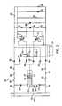
- FIG. 1is a schematic circuit diagram of a surge protector that fails as an open circuit having LED notification, according to an embodiment of the invention
- FIG. 2is a schematic circuit diagram of a surge protector that fails as an open circuit without LED notification, according to an embodiment of the invention
- FIG. 3is a schematic circuit diagram of a surge protector that fails as an open circuit having LED notification and incorporating a delay, according to an embodiment of the invention.
- FIG. 4is a perspective view of components of a surge protection device that fails as an open circuit, according to an embodiment of the invention.
- FIG. 1a schematic circuit diagram 100 is shown for a surge protector that fails as an open circuit and has light-emitting diode (LED) notification.
- the surge protector incorporating the schematic circuit diagram 100is designed to offer surge protection and, at the moment or close to the moment a surge protection component or components fail, use a relay, contactor, or other switching device to open a circuit path, as discussed in greater detail herein.
- the schematic circuit diagram 100includes a number of different electrical components, such as a surge protection element (e.g. gas tube), a relay, resistors and diodes that may be attached or mounted to a printed circuit board, as discussed in greater detail for FIG. 4 .
- the schematic circuit diagram 100will be described with reference to specific electrical components to achieve specific operation and/or power requirements. However, other electrical components and/or component values or configurations may be used to achieve other desired characteristics in alternative embodiments.
- the schematic circuit diagram 100includes a first signal rail 101 extending along a path from line input 102 to line output 104 .
- the schematic circuit diagram 100also includes a second signal rail 103 extending along a path from a line input 112 to a line output 114 .
- a non-surge signal present at the line input 102may travel to the line output 104 and a non-surge signal applied at the line input 112 may travel to the line output 114 .
- Equipment connected at line outputs 104 or 114may also be vulnerable to current or voltage surges that can propagate along either the first signal rail 101 or the second signal rail 103 .
- Inductances ( 120 , 122 )may be present along the first signal rail 101 and/or the second signal rail 103 .
- the line input 102may be directly connected to the line output 104 or the line input 112 may be directly connected to the line output 114 .
- a surge protection device or surge protection componentis electrically connected to the first signal rail 101 and the second signal rail 103 , as discussed in greater detail herein.
- a surge protection device embodying the schematic circuit diagram 100may be a three-terminal device with a first terminal for connecting to the first signal rail 101 , a second terminal for connecting to the second signal rail 103 and a third terminal for connecting to a ground 180 .
- Various componentsare thus coupled between or off of the first signal rail 101 and/or the second signal rail 103 to ground 180 for diverting of surge signals off of the first signal rail 101 and/or the second signal rail 103 before the surge signals can encounter or damage any connected system or equipment.
- a surge protection element 170is connected through a relay 160 to the first signal rail 101 and the second signal rail 103 .
- the surge protection element 170may be a gas tube as shown or, alternatively, a TVS diode, a MOV, or any other type of surge protection element for conducting or shunting a surge to ground and away from any protected systems or equipment.
- the relay 160has a coil 166 for controlling the positioning of two switches ( 162 , 164 ). Upon energizing the coil 166 , the switch 162 moves or switches from its first position (currently demonstrated in FIG. 1 ) to its secondary position (as shown by dashed line 163 ) and engages its currently unconnected contact.
- the switch 164moves or switches from its first position (currently demonstrated in FIG. 1 ) to its secondary position (as shown by dashed line 165 ) and engages its currently unconnected contact.
- the relay 160forms an open circuit with respect to surges on the first signal rail 101 and the second signal rail 103 when the switches ( 162 , 164 ) are in their secondary positions ( 163 , 165 ), as discussed in greater detail herein.
- the surge protection element 170During non-surge events and without any failure of the surge protection element 170 , currents and voltages flow along the first and second signal rails ( 101 , 103 ) to any connected system or equipment. Upon propagation of a surge signal along either the first signal rail 101 or the second signal rail 103 , the surge protection element 170 begins to conduct, thus shorting or shunting the surge to ground 180 . However, the surge protection element 170 may fail as a short, and thus directly connect the ground 180 to either or both of the first or second signal rails ( 101 , 103 ), even during non-surge events.
- the surge protection element 170may be a 3-pole gas tube with Trigard technology that is specified to fail short, such as after 20 total 20 kA surges or 1 total 40 kA surge. Such shorted failure operation can cause severe safety issues and/or disrupt the operations of any connected system or equipment. In light of such failures, the relay 160 operates to maintain an open circuit between the first signal rail 101 and ground 180 and the second signal rail 103 and ground 180 , even though the surge protection element 170 has failed as a short.
- a bridge full wave rectifier 137 made up of four diodes ( 130 , 132 , 134 , 136 )is connected to the first and second signal rails ( 101 , 103 ) and to the coil 166 of the relay 160 .
- the rectifier 137converts AC signals on the first and second signal rails ( 101 , 103 ) to a DC signal for use by the coil 166 of the relay 160 .
- the rectifier 137may specify high surge current capability along with low leakage current for surviving surge signals. Alternative configurations for rectification may also be utilized in an alternative embodiment.
- no rectificationmay be needed, for example if the coil 166 of the relay 160 is an AC coil and the first and second signal rails ( 101 , 103 ) propagate AC signals, or if the coil 166 of the relay 160 is a DC coil and the first and second signal rails ( 101 , 103 ) propagate DC signals.
- the surge protection element 170has not failed as a short, there exists an open connection between the coil 166 of the relay 160 and ground 180 , thus prohibiting a signal path through the rectifier 137 , the coil 166 , and to ground 180 .
- the relay 160is thus powered down and completely passive when the surge protection element 170 has not failed as a short.
- a conductive path to ground 180is created, thus energizing the coil 166 of the relay 160 .
- the switches ( 162 , 164 ) of the relay 160subsequently switch to their secondary positions ( 163 , 165 ) or configurations, thus creating an open circuit between the first signal rail 101 and ground 180 and the second signal rail 103 and ground 180 , despite the failure short of the surge protection element 170 .
- neither the first nor second signal rails ( 101 , 103 )have surge protection.
- two notification LEDs ( 150 , 152 )are employed.
- the switches ( 162 , 164 ) of the relay 160are switched to their secondary positions ( 163 , 165 ) upon energizing the coil 166 , a conductive path through the notification LEDs ( 150 , 152 ) and their associated current limiting resistors ( 142 , 140 ) is created.
- a usermay identify when replacement of the surge protection element 170 is required by examining the state of the notification LEDs ( 150 , 152 ). Greater or fewer of the notification LEDs ( 150 , 152 ) may be utilized in an alternative embodiment.
- the relay 160may operate a mechanical component that visibly shifts its position depending upon the orientation of either or both of the two switches ( 162 , 164 ). In still another embodiment, no notification may be utilized.
- the relay 160if the relay 160 survives a surge event and the surge protection element 170 fails short, then the relay 160 engages and both the first and second signal rails ( 101 , 103 ) are opened to ground 180 without protection. If the surge protection element 170 survives a surge event, then the two switches ( 162 , 164 ) of the relay 160 switches remain as shown and the circuit continues to function normally with the notification LEDs ( 150 , 152 ) off and minimum power being consumed. If the relay 160 does not survive a surge event, then the switches ( 162 , 164 ) are burned or fail open and both the first and second signal rails ( 101 , 103 ) are opened without protection.
- the relay 160may be a double pole, double throw relay as shown or may include multiple single pole double throw switches. In an alternative embodiment, any number of switches, poles or throws may be utilized depending upon desired notification or circuit characteristics. In addition, any alternative switching components may be utilized in place of the relay 160 in other embodiments.
- FIG. 2a schematic circuit diagram 200 is shown for a surge protector device that fails as an open circuit and does not utilize LED notification.
- the schematic circuit diagram 200is designed to offer surge protection and, at the moment or close to the moment a surge protection component or components of the schematic circuit diagram 200 fail, control a relay or other switching device to open the circuit, as discussed in greater detail herein.
- the schematic circuit diagram 200includes a number of different electrical components, such as TVS diodes, a gas tube, a relay, resistors, capacitors and diodes that may be attached or mounted to a printed circuit board or otherwise coupled to a frame or housing of the surge protector device, as discussed in greater detail for FIG. 4 .
- the schematic circuit diagram 200will be described with reference to specific electrical components to achieve specific operation and/or power requirements. However, other electrical components and/or component value or configurations may be used to achieve other desired characteristics in alternative embodiments.
- the schematic circuit diagram 200includes a first connection 202 for connecting to a first signal line 201 and a second connection 204 for connecting to a second signal line 203 .
- the first connection 202may be made via a first signal terminal of the surge protector device incorporating the schematic circuit diagram 200 and the second connection 204 may be made via a second signal terminal of the surge protector device incorporating the schematic circuit diagram 200 .
- a surge signal that propagates along the first signal line 201will thus make electrical contact with the first connection 202 of the surge protector device incorporating the schematic circuit diagram 200 .
- a surge signal that propagates along the second signal line 203will thus make electrical contact with the second connection 204 of the surge protector device incorporating the schematic circuit diagram 200 .
- Any systems or equipment connected to the first signal line 201 or the second signal line 203will thus be protected from such surge signals since the surge may be safely diverted away, as discussed in greater detail herein.
- TVS diodes ( 210 , 212 ) and a gas tube 218will begin to conduct and thus divert the surge signal away from either or both of the first signal line 201 or the second signal line 203 to a ground connection 299 .
- the TVS diodes ( 210 , 212 )may be 20V, 10 kA diodes.
- the TVS diode 210may be a 45V, 391.5 A diode while the TVS diode 212 may be a 28V, 606 A diode.
- any surge protection components or elementsmay be used in replacement of or in addition to any or all of the TVS diodes ( 210 , 212 ) or the gas tube 218 .
- the ground connection 299may be made via a ground terminal of the surge protector device incorporating the schematic circuit diagram 200 .
- a switching device 214 having a first switch 215 , a second switch 216 , and a third switch 217is connected to the TVS diodes ( 210 , 212 ) and the gas tube 218 .
- the switching device 214allows for the transmittal or prevention of one or more signals to conduct through one or more of the TVS diodes ( 210 , 212 ) and through the gas tube 218 to the ground connection 299 .
- signal paths between either or both of the TVS diodes ( 210 , 212 ) and the gas tube 218are shorted or opened.
- a solenoid 278 or other switch control deviceis configured to change the configuration of the first switch 215 , the second switch 216 , and/or the third switch 217 when the solenoid 278 is activated by a flowing electrical current.
- the solenoid 278may simultaneously change the configuration of the first switch 215 , the second switch 216 , and/or the third switch 217 .
- a plurality of diodesserve as a full wave rectifier bridge to create DC power under non-surge conditions.
- Diodes ( 258 , 259 )are used if one or both of the TVS diodes ( 210 , 212 ) fail as a short, and operate to become half of a power supply bridge to optocouplers ( 276 , 274 ), as discussed in greater detail herein.
- the diodes ( 250 , 252 , 254 , 256 , 258 , 259 )may be MR854 diodes.
- Filter capacitors( 260 , 262 , 264 , 296 ) provide some electrical charge storage capacity and aid in stabilizing what may be sporadic AC signals present upon the first and second signal lines ( 201 , 203 ) to which the surge protector device incorporating the schematic circuit diagram 200 is connected.
- the capacitors ( 260 , 262 , 264 )may be 470 uF, 25 Vdc capacitors while the capacitor 296 may be a 9 F, 3 Vdc capacitor.
- Diodes ( 284 , 286 , 290 )are included for preventing false triggering of the solenoid 278 .
- Diodes ( 284 , 290 )may be 3V diodes while the diode 286 may be a 30V diode.
- Resistors ( 230 , 232 , 270 , 280 , 282 , 281 )may be included for current limiting purposes. Resistors ( 230 , 232 , 270 ) may be 4.7 ohm resistors. Resistors ( 280 , 282 ) may be 330 ohm resistors. Resistor 281 may be a 5.6 k ohm resistor. Fuses ( 220 , 222 ) are connected to the first connection 202 and the second connection 204 , respectively, and are configured to open in the event of an overcurrent of a particular threshold caused by failure of one or more of the previously described components. The fuses ( 220 , 222 ) may be 0.5 amp fuses.
- Inductors ( 240 , 242 )may be connected in a serial configuration with the fuses ( 220 , 222 ), respectively.
- the inductors ( 240 , 242 )may be 1 mH inductors. Any or all of the previously described various components may be connected in differing configurations, chosen to have differing values, omitted completely, or connected with additional circuit components without departing from the spirit of the invention for providing a fail open surge protection device.
- the first switch 215 , the second switch 216 , and the third switch 217 of the switching device 214are in a normally-closed configuration or position as shown.
- a conductive pathis created through either or both of the TVS diodes ( 210 , 212 ), through one or more of the switches ( 215 , 216 , 217 ) of the switching device 214 , through one or both of the diodes ( 258 , 259 ), and through one or both of the optocouplers ( 276 , 274 ).
- a currentis allowed to flow through the solenoid 278 .
- the solenoid 278controls the positioning of the first switch 215 , the second switch 216 , and the third switch 217 of the switching device 214 .
- the three switches of the switching device 214are positioned or configured in the normally-closed position or configuration and minimal power is consumed.
- the solenoid 278is energized and opens the three switches ( 215 , 216 , 217 ) in the switching device 214 .
- greater or fewer switchesmay be incorporated as part of the switching device 214 or may be discrete components not part of any switching device 214 .
- the solenoid 278may be any type of controlling component, such as a gear motor, configured to change a configuration of one or more of the switches ( 215 , 216 , 217 ) used for opening or closing a signal path through any of the TVS diodes ( 210 , 212 ) to the ground connection 299 .
- a delaymay be incorporated after failure of any or all of TVS diodes ( 210 , 212 ) and before energization of the solenoid 278 , as described in more detail for FIG. 3 .
- a visual element for notifying a user when any or all of the switches ( 215 , 216 , 217 ) are in their open position or configurationmay be included.
- This visual elementmay be a light-emitting diode or any other type of indicator that is visible to a user.
- other forms of user notificationmay be utilized, for example, providing an audible noise or chime, or by providing an output signal, connectible to other circuits or systems.
- a schematic circuit diagram 300is shown of a surge protector including LED notification and that fails as an open circuit after a delay.
- the schematic circuit diagram 300may have certain structure and functional features that are similar to those of the schematic circuit diagram 100 , previously described for FIG. 1 . Notwithstanding these similarities, the schematic circuit diagram 300 may be distinguished from the schematic circuit diagram 100 based primarily on the addition of a delay before opening a circuit path after failure of a surge protection element as a short.
- the schematic circuit diagram 300includes a first signal rail 301 extending along a path from a line input 302 to a line output 304 .
- the schematic circuit diagram 300also includes a second signal rail 303 extending along a path from a line input 312 to a line output 314 .
- a surge protection element 370is connected between a ground 380 and through a relay 360 to the first signal rail and the second signal rail.
- the surge protection element 370may be a gas tube, a TVS diode, a MOV, or any other type of surge protection element, the same or similar to the surge protection element 170 of FIG. 1 .
- the relay 360has a coil 366 for controlling the positioning of two switches ( 362 , 364 ). The same or similar to the schematic circuit diagram 100 of FIG.
- the switch 362moves or switches from its first position (currently demonstrated in FIG. 3 ) to its secondary position (as shown by dashed line 363 ) and engages its currently unconnected contact.
- the switch 364moves or switches from its first position (currently demonstrated in FIG. 3 ) to its secondary position (as shown by dashed line 365 ) and engages its currently unconnected contact.
- a bridge full wave rectifier 337 made up of four diodes ( 330 , 332 , 334 , 336 )is connected to the first and second signal rails ( 301 , 303 ) and to the coil 366 of the relay 360 .
- Alternative rectification methods, or no rectification means,may be utilized in alternative embodiments, as previously discussed for FIG. 1 .
- Operation of the circuit shown by the schematic circuit diagram 300is similar to the schematic circuit diagram 100 and utilizes notification LEDs ( 350 , 352 ) with current limiting resistors ( 340 , 342 ) to indicate when the switches ( 362 , 364 ) are in their secondary positions ( 363 , 365 ).
- a delayis created by a capacitor 390 connected across the coil 366 of the relay 360 to the ground 380 .
- the capacitor 390creates a delay after the failure of the surge protection element 370 before the coil 366 of the relay 360 is energized, thus delaying the switching of the switches ( 362 , 364 ).
- This delayeliminates a momentary short seen across the first and second signal rails ( 301 , 303 ) that otherwise occurs when the coil 366 is permitted to energize immediately upon the surge protection element 370 failing as a short.
- other circuit configurationsmay be used to incorporate the above described delay.
- Other aspects of the schematic circuit diagram 300may be the same or similar to those previously discussed for FIG. 1 .
- FIG. 4shows a perspective view of components of a surge protection device 400 that fails as an open circuit.
- the surge protection device 400includes a frame 401 to which a printed circuit board 406 is coupled for providing surge protection components thereon.
- the printed circuit board 406 and/or the frame 401may include various circuit components and/or electrical terminals for providing surge protection to a user's system or equipment via one or more connected signal lines, for example, by incorporating a circuit shown by any of the schematic circuit diagrams 100 , 200 , or 300 , previously described for FIGS. 1-3 .
- the printed circuit board 406may be mounted to the frame mechanically via screws, brackets, adhesives, or any other form of attachment.
- a ground pin 408is coupled with the frame for providing a ground reference and is in electrical contact with one or more components of the printed circuit board 406 .
- a solenoid 404 or other switch controlling componentis coupled with the frame 401 and interfaces with a switch 402 , also coupled with the frame 401 , for operation as discussed in greater detail for FIGS. 1-3 .
- the switch 402may have any number of contacts or, if multiple switching paths are desired, a plurality of switches may be utilized, each switch changing configuration or position in response to energization of the solenoid 404 or other switch controlling component.
- the switch 402may be configured to provide a visual indication or notification to a user based upon the configuration or position of the switch 402 , for example by physically shifting a mechanical component 403 of the switch 402 that is viewable by a user when the switch 402 changes configuration or position.
- lights or other indicatorsmay be disposed on the printed circuit board 406 or otherwise coupled to the frame 401 of the surge protection device 400 for notification purposes to a user.
Landscapes
- Emergency Protection Circuit Devices (AREA)
Abstract
Description
Claims (21)
Priority Applications (1)
| Application Number | Priority Date | Filing Date | Title |
|---|---|---|---|
| US13/330,497US8730637B2 (en) | 2010-12-17 | 2011-12-19 | Surge protection devices that fail as an open circuit |
Applications Claiming Priority (2)
| Application Number | Priority Date | Filing Date | Title |
|---|---|---|---|
| US201061424444P | 2010-12-17 | 2010-12-17 | |
| US13/330,497US8730637B2 (en) | 2010-12-17 | 2011-12-19 | Surge protection devices that fail as an open circuit |
Publications (2)
| Publication Number | Publication Date |
|---|---|
| US20120154167A1 US20120154167A1 (en) | 2012-06-21 |
| US8730637B2true US8730637B2 (en) | 2014-05-20 |
Family
ID=46233664
Family Applications (1)
| Application Number | Title | Priority Date | Filing Date |
|---|---|---|---|
| US13/330,497Expired - Fee RelatedUS8730637B2 (en) | 2010-12-17 | 2011-12-19 | Surge protection devices that fail as an open circuit |
Country Status (1)
| Country | Link |
|---|---|
| US (1) | US8730637B2 (en) |
Families Citing this family (6)
| Publication number | Priority date | Publication date | Assignee | Title |
|---|---|---|---|---|
| US10440783B2 (en)* | 2014-03-24 | 2019-10-08 | BSH Hausgeräte GmbH | Cooking appliance device having a self-controlling bypassing unit |
| US10483706B2 (en) | 2017-01-20 | 2019-11-19 | Automatic Switch Company | Solenoid coil with replaceable status indicator light |
| WO2020036829A2 (en)* | 2018-08-13 | 2020-02-20 | The Vollrath Company, L.L.C. | Ac controlled relay drive circuit |
| FR3087614B1 (en)* | 2018-10-19 | 2020-10-09 | Sagemcom Energy & Telecom Sas | ELECTRICAL BOARD INCLUDING A RECOVERY BRIDGE |
| US11277002B2 (en)* | 2019-05-13 | 2022-03-15 | Mersen Usa Ep Corp. | Surge protection device for the protection of multiple DC or AC power lines |
| KR20230019352A (en)* | 2021-07-30 | 2023-02-08 | 삼성디스플레이 주식회사 | Display apparatus |
Citations (128)
| Publication number | Priority date | Publication date | Assignee | Title |
|---|---|---|---|---|
| US2030179A (en) | 1933-01-19 | 1936-02-11 | American Telephone & Telegraph | Electrical circuit arrangement |
| US3167729A (en) | 1962-10-29 | 1965-01-26 | Sylvania Electric Prod | Microwave filter insertable within outer wall of coaxial line |
| US3323083A (en) | 1965-03-17 | 1967-05-30 | Amp Inc | Means and method for transmission line compensation |
| US3619721A (en) | 1970-06-01 | 1971-11-09 | Gen Electric | Triggered vacuum gap keep-alive circuit |
| US3663901A (en) | 1970-02-27 | 1972-05-16 | Amp Inc | Tuned coaxial device |
| US3731234A (en) | 1971-12-27 | 1973-05-01 | Bell Telephone Labor Inc | Combined voice frequency transmission and dc signaling circuit |
| US3750053A (en) | 1972-04-24 | 1973-07-31 | Plessey Inc | Coaxial transmission line rf switch |
| US3783178A (en) | 1972-08-03 | 1974-01-01 | Gen Signal Corp | Expansion joint for connecting rigid conduit with grounding continuity |
| US3831110A (en) | 1972-05-01 | 1974-08-20 | Cornell Res Foundation Inc | Multi-axis cavities for microwave semiconductors |
| US3845358A (en) | 1973-06-29 | 1974-10-29 | Gen Electric | Integrated polycrystalline varistor surge protective device for high frequency applications |
| US3944937A (en) | 1973-12-06 | 1976-03-16 | Matsushita Electric Industrial Co., Ltd. | Broad-band signal transmitting device using transformer |
| US3980976A (en) | 1974-03-28 | 1976-09-14 | Sony Corporation | Coaxial connector |
| US4046451A (en) | 1976-07-08 | 1977-09-06 | Andrew Corporation | Connector for coaxial cable with annularly corrugated outer conductor |
| US4047120A (en) | 1976-07-15 | 1977-09-06 | The United States Of America As Represented By The Secretary Of The Navy | Transient suppression circuit for push-pull switching amplifiers |
| US4112395A (en) | 1977-06-10 | 1978-09-05 | Cincinnati Electronics Corp. | Method of and apparatus for matching a load circuit to a drive circuit |
| US4262317A (en) | 1979-03-22 | 1981-04-14 | Reliable Electric Company | Line protector for a communications circuit |
| US4356360A (en) | 1981-02-26 | 1982-10-26 | Amf Incorporated | Pull-to-turn switch |
| US4359764A (en) | 1980-04-08 | 1982-11-16 | Block Roger R | Connector for electromagnetic impulse suppression |
| US4384331A (en) | 1979-04-23 | 1983-05-17 | Nissan Motor Company, Limited | Noise suppressor for vehicle digital system |
| US4409637A (en) | 1980-04-08 | 1983-10-11 | Block Roger R | Connector for electromagnetic impulse suppression |
| US4481641A (en) | 1982-09-30 | 1984-11-06 | Ford Motor Company | Coaxial cable tap coupler for a data transceiver |
| US4554608A (en) | 1982-11-15 | 1985-11-19 | Block Roger R | Connector for electromagnetic impulse suppression |
| US4563720A (en) | 1984-04-17 | 1986-01-07 | General Semiconductor Industries, Inc. | Hybrid AC line transient suppressor |
| US4586104A (en) | 1983-12-12 | 1986-04-29 | Rit Research Corp. | Passive overvoltage protection devices, especially for protection of computer equipment connected to data lines |
| US4689713A (en) | 1985-06-12 | 1987-08-25 | Les Cables De Lyon | High voltage surge protection for electrical power line |
| US4698721A (en) | 1983-11-07 | 1987-10-06 | Puroflow Corp. | Power line filter for transient and continuous noise suppression |
| US4727350A (en) | 1986-04-28 | 1988-02-23 | Hitoshi Ohkubo | Surge absorber |
| US4952173A (en) | 1986-09-05 | 1990-08-28 | Raychem Pontoise | Circuit protection device |
| CH675933A5 (en) | 1989-07-27 | 1990-11-15 | Huber+Suhner Ag | Triaxial electromagnetic pulse conductor - has inner conductor and two screening conductors with unit to maintain contact with overload conductor |
| US4984146A (en) | 1990-03-27 | 1991-01-08 | International Business Machines Corporation | Suppression of radiated EMI for power supplies |
| US4985800A (en) | 1989-10-30 | 1991-01-15 | Feldman Nathan W | Lighting protection apparatus for RF equipment and the like |
| US5053910A (en) | 1989-10-16 | 1991-10-01 | Perma Power Electronics, Inc. | Surge suppressor for coaxial transmission line |
| US5057964A (en) | 1986-12-17 | 1991-10-15 | Northern Telecom Limited | Surge protector for telecommunications terminals |
| US5102818A (en) | 1989-09-21 | 1992-04-07 | Deutsche Itt Industries Gmbh | Method for the smooth fine classification of varactor diodes |
| US5122921A (en) | 1990-04-26 | 1992-06-16 | Industrial Communication Engineers, Ltd. | Device for electromagnetic static and voltage suppression |
| US5124873A (en) | 1989-10-30 | 1992-06-23 | Efi Corporation | Surge suppression circuit for high frequency communication networks |
| US5142429A (en) | 1990-05-07 | 1992-08-25 | Telefonaktiebolaget L M Ericsson | Overvoltage and overcurrent protective circuit with high earth balance |
| US5166855A (en) | 1991-02-27 | 1992-11-24 | Semitron Industries Ltd. | Surge protector with thermal failsafe |
| US5170151A (en)* | 1991-02-21 | 1992-12-08 | Hochstein Peter A | Method and assembly for disconnecting a battery from its operating system |
| US5278720A (en) | 1991-09-20 | 1994-01-11 | Atlantic Scientific Corp. | Printed circuit-mounted surge suppressor matched to characteristic impedance of high frequency transmission line |
| US5321573A (en) | 1992-07-16 | 1994-06-14 | Dale Electronics, Inc. | Monolythic surge suppressor |
| US5353189A (en) | 1992-11-02 | 1994-10-04 | Tomlinson John C | Surge protector for vehicular traffic monitoring equipment |
| US5412526A (en)* | 1993-02-10 | 1995-05-02 | Square D Company | Surge arrester circuit and housing therefor |
| US5442330A (en) | 1993-12-27 | 1995-08-15 | Motorola, Inc. | Coupled line filter with improved out-of-band rejection |
| US5537044A (en) | 1994-09-30 | 1996-07-16 | The United States Of America As Represented By The Secretary Of The Navy | Surge voltage generator for pulsing grounded and ungrounded electrical equipment |
| US5611224A (en) | 1993-10-29 | 1997-03-18 | The Eastern Company | Handle operable rotary latch and lock |
| US5617284A (en) | 1994-08-05 | 1997-04-01 | Paradise; Rick | Power surge protection apparatus and method |
| US5625521A (en) | 1994-07-22 | 1997-04-29 | Pacusma Co.,Ltd. | Surge protection circuitry |
| US5667298A (en) | 1996-01-16 | 1997-09-16 | Cedarapids, Inc. | Portable concrete mixer with weigh/surge systems |
| US5721662A (en) | 1992-07-29 | 1998-02-24 | Act Communications, Inc. | Floating ground isolator for a communications cable locating system |
| US5781844A (en) | 1995-03-22 | 1998-07-14 | Scientific-Atlanta, Inc. | Method and apparatus for distributing a power signal and an RF signal |
| US5790361A (en) | 1997-03-31 | 1998-08-04 | The Whitaker Corporation | Coaxial surge protector with impedance matching |
| US5798790A (en) | 1995-09-22 | 1998-08-25 | International Business Machines Corp. | Display apparatus with gamma measurement |
| US5844766A (en) | 1997-09-09 | 1998-12-01 | Forem S.R.L. | Lightning supression system for tower mounted antenna systems |
| US5854730A (en) | 1997-09-15 | 1998-12-29 | Mitchell; Dennis | Transient and voltage surge protection system and method for preventing damage to electrical equipment |
| US5953195A (en) | 1997-02-26 | 1999-09-14 | Reltec Corporation | Coaxial protector |
| US5966283A (en) | 1995-08-18 | 1999-10-12 | Act Communications, Inc. | Surge suppression for radio frequency transmission lines |
| US5982602A (en) | 1993-10-07 | 1999-11-09 | Andrew Corporation | Surge protector connector |
| US5986869A (en) | 1998-02-05 | 1999-11-16 | Polyphaser Corporation | Grounding panel |
| US6054905A (en) | 1998-01-21 | 2000-04-25 | General Instrument Coporation | User configurable CATV power inserter |
| US6061223A (en) | 1997-10-14 | 2000-05-09 | Polyphaser Corporation | Surge suppressor device |
| US6060182A (en) | 1997-06-09 | 2000-05-09 | Teikoku Piston Ring Co., Ltd. | Hard coating material, sliding member covered with hard coating material and manufacturing method thereof |
| US6086544A (en) | 1999-03-31 | 2000-07-11 | Ethicon Endo-Surgery, Inc. | Control apparatus for an automated surgical biopsy device |
| US6137352A (en) | 1997-01-27 | 2000-10-24 | Huber And Suhner Ag | Circuit arrangement for protection of HF-input-circuit on telecommunications devices |
| US6141194A (en) | 1998-09-22 | 2000-10-31 | Simmonds Precision Products, Inc. | Aircraft fuel tank protective barrier and method |
| US6177849B1 (en) | 1998-11-18 | 2001-01-23 | Oneline Ag | Non-saturating, flux cancelling diplex filter for power line communications |
| US6226166B1 (en) | 1997-11-28 | 2001-05-01 | Erico Lighting Technologies Pty Ltd | Transient overvoltage and lightning protection of power connected equipment |
| US6243247B1 (en) | 1998-09-22 | 2001-06-05 | Polyphaser Corporation | Stripline transient protection device |
| US6252755B1 (en) | 1999-08-11 | 2001-06-26 | Advanced Micro Devices, Inc. | Apparatus and method for implementing a home network using customer-premises power lines |
| US6281690B1 (en) | 1996-07-19 | 2001-08-28 | Lockheed Martin Corporation | Coaxial radio frequency test probe |
| US6342998B1 (en) | 1998-11-13 | 2002-01-29 | Leviton Manufacturing Co., Inc. | Data surge protection module |
| US6381283B1 (en) | 1998-10-07 | 2002-04-30 | Controlnet, Inc. | Integrated socket with chip carrier |
| US6385030B1 (en) | 1999-09-02 | 2002-05-07 | Marconi Communications, Inc. | Reduced signal loss surge protection circuit |
| US6394122B1 (en) | 2000-09-21 | 2002-05-28 | Pacific Seismic Products, Inc. | Shock actuated sensor for fluid valve |
| US6421220B2 (en) | 1998-05-29 | 2002-07-16 | Porta Systems Corporation | Low capacitance surge protector for high speed data transmission |
| US20020167302A1 (en) | 2001-05-09 | 2002-11-14 | Gallavan Michael F. | Surge current measurement |
| US20020191360A1 (en) | 2001-05-22 | 2002-12-19 | Enrico Colombo | Current detector for surge arrester diagnostic and overvoltage assessment in high voltage substations |
| US6502599B1 (en) | 2000-09-21 | 2003-01-07 | Pacific Seismic Products, Inc. | Shock actuated responsive mechanism for vertical fluid valve assemblies |
| US6527004B1 (en) | 2000-09-21 | 2003-03-04 | Pacific Seismic Products, Inc. | Shock actuated responsive mechanism for vertical fluid valve assemblies |
| US6535369B1 (en)* | 2000-06-16 | 2003-03-18 | Teal Electronics Corporation | Adaptive surge suppressor |
| US20030072121A1 (en) | 2001-10-12 | 2003-04-17 | Polyphaser Corporation | Rf surge protection device |
| US20030211782A1 (en) | 2002-05-07 | 2003-11-13 | Mr. Joseph Lorenzo De Guzman | Filtered RJ11 connector module with LED indicators and method of manufacturing |
| US6650203B2 (en) | 2000-03-21 | 2003-11-18 | Diehl Avionik Gmbh | Filter arrangement |
| US20040042149A1 (en) | 2002-04-15 | 2004-03-04 | Edward Devine | Surge lightning protection device |
| US6721155B2 (en) | 2001-08-23 | 2004-04-13 | Andrew Corp. | Broadband surge protector with stub DC injection |
| US6754060B2 (en) | 2000-07-06 | 2004-06-22 | George M. Kauffman | Protective device |
| US20040121648A1 (en) | 2002-07-26 | 2004-06-24 | V-Squared Networks | Network device for communicating information |
| US6757152B2 (en) | 2001-09-05 | 2004-06-29 | Avx Corporation | Cascade capacitor |
| US20040145849A1 (en) | 2002-11-15 | 2004-07-29 | Chang Byung-Ho | Surge protection device and method |
| US6782329B2 (en) | 1998-02-19 | 2004-08-24 | Square D Company | Detection of arcing faults using bifurcated wiring system |
| US6789560B1 (en) | 2000-09-21 | 2004-09-14 | Pacific Seismic Products, Inc. | Shock actuated responsive mechanism with improved safety means to prevent over-rotation of the valve reset mechanism |
| US6814100B1 (en) | 2000-09-21 | 2004-11-09 | Pacific Seismic Products, Inc. | Shock actuated responsive mechanism with means to enable a remote detecting means to determine that the valve assembly has been closed |
| US6816348B2 (en) | 2001-05-18 | 2004-11-09 | Compal Electronics, Inc. | Input protection circuit of a handheld electric device |
| US20040264087A1 (en) | 2003-06-30 | 2004-12-30 | Bishop Roger S | Transient protector for wireless communications equipment |
| US20050036262A1 (en) | 2003-07-09 | 2005-02-17 | Siebenthall Fred Mac | DC Voltage surge suppressor with distributed capacitance EMI filtering and impedance matching |
| US20050044858A1 (en) | 2003-08-26 | 2005-03-03 | Kenneth Hooker | Two stage solenoid control valve |
| US20050176275A1 (en) | 2004-02-05 | 2005-08-11 | Panamax | Modular signal and power connection device |
| US20050185354A1 (en) | 2004-02-25 | 2005-08-25 | Hoopes Gerald B. | Protection of A/V components |
| US6968852B1 (en) | 2000-09-21 | 2005-11-29 | Pacific Seismic Products, Inc. | Shock actuated responsive mechanism with improved dual safety means to prevent over-rotation of the valve reset mechanism and to provide easy access to the reset knob |
| US6975496B2 (en) | 2002-03-21 | 2005-12-13 | Polyphaser Corporation | Isolated shield coaxial surge suppressor |
| US20060038635A1 (en) | 2004-08-17 | 2006-02-23 | Dominick Richiuso | Integrated passive filter incorporating inductors and ESD protectors |
| US20060120005A1 (en) | 2004-11-15 | 2006-06-08 | Van Sickle Robert J | Transient voltage surge suppression systems |
| US20060139832A1 (en) | 2004-12-29 | 2006-06-29 | Hewlett-Packard Development Company, L.P. | Common mode surge protection filter |
| US20060146458A1 (en) | 2005-01-03 | 2006-07-06 | Huberag | Surge suppressor with increased surge current capability |
| US7082022B2 (en) | 2002-05-31 | 2006-07-25 | Polyphaser Corporation | Circuit for diverting surges and transient impulses |
| US7092230B2 (en) | 2002-06-26 | 2006-08-15 | Huber & Suhner Ag | Interference filter and lightning conductor device |
| US7106572B1 (en) | 1999-09-17 | 2006-09-12 | Adee Electronic (Societe A Responsabilite Limitee) | Device for protecting against voltage surges |
| US7130103B2 (en) | 2004-03-08 | 2006-10-31 | Seiko Epson Corporation | Optical modulator and manufacturing method of optical modulator |
| US7159236B2 (en) | 2000-06-30 | 2007-01-02 | Kabushiki Kaisha Toshiba | Transmission/reception integrated radio-frequency apparatus |
| US20070053130A1 (en) | 2005-09-01 | 2007-03-08 | Andrew Corporation | Offset Planar Coil Coaxial Surge Suppressor |
| US20070097583A1 (en) | 2005-10-31 | 2007-05-03 | Andrew Corporation | Tuned Coil Coaxial Surge Suppressor |
| US20070095400A1 (en) | 2005-11-03 | 2007-05-03 | Parker-Hannifin Corporation | Shut-off valve system |
| US20070139850A1 (en) | 2005-12-15 | 2007-06-21 | Raycap Corporation | Overvoltage protection devices including wafer of varistor material |
| US7250829B2 (en) | 2001-09-14 | 2007-07-31 | Matsushita Electric Industrial Co., Ltd. | High frequency switch |
| US7338547B2 (en) | 2003-10-02 | 2008-03-04 | Laird Technologies, Inc. | EMI-absorbing air filter |
| US7371970B2 (en) | 2002-12-06 | 2008-05-13 | Flammer Jeffrey D | Rigid-flex circuit board system |
| US7430103B2 (en) | 2003-09-19 | 2008-09-30 | Sharp Kabushiki Kaisha | Static electricity protective circuit and high-frequency circuit apparatus incorporating the same |
| US7453268B2 (en) | 2005-06-29 | 2008-11-18 | Delphi Technologies, Inc. | Input power protected ratiometric output sensor circuit |
| US7471172B2 (en) | 2003-05-02 | 2008-12-30 | Lgp Allgon Ab | Microwave transmission unit including lightning protection |
| US7507105B1 (en) | 2007-07-17 | 2009-03-24 | Ventek, Llc | Hazardous area coupler device |
| US20090103226A1 (en) | 2007-10-18 | 2009-04-23 | Polyphaser Corporation | Surge suppression device having one or more rings |
| US20090109584A1 (en) | 2007-10-30 | 2009-04-30 | Polyphaser Corporation | Surge protection circuit for passing dc and rf signals |
| US20090284888A1 (en) | 2008-05-19 | 2009-11-19 | Polyphaser Corporation | Dc and rf pass broadband surge suppressor |
| US7623332B2 (en) | 2008-01-31 | 2009-11-24 | Commscope, Inc. Of North Carolina | Low bypass fine arrestor |
| US20090296430A1 (en) | 2008-05-29 | 2009-12-03 | Airbus France | Pre-charging device for a chopping converter, and an assembly and aircraft comprising it |
| US7817398B1 (en) | 2007-11-14 | 2010-10-19 | Sprint Communications Company L.P. | Surge arrestor mounting system |
| US20110080683A1 (en) | 2009-10-02 | 2011-04-07 | Jones Jonathan L | Rf coaxial surge protectors with non-linear protection devices |
| US20110159727A1 (en) | 2009-12-28 | 2011-06-30 | Matt Howard | Power distribution device |
- 2011
- 2011-12-19USUS13/330,497patent/US8730637B2/ennot_activeExpired - Fee Related
Patent Citations (137)
| Publication number | Priority date | Publication date | Assignee | Title |
|---|---|---|---|---|
| US2030179A (en) | 1933-01-19 | 1936-02-11 | American Telephone & Telegraph | Electrical circuit arrangement |
| US3167729A (en) | 1962-10-29 | 1965-01-26 | Sylvania Electric Prod | Microwave filter insertable within outer wall of coaxial line |
| US3323083A (en) | 1965-03-17 | 1967-05-30 | Amp Inc | Means and method for transmission line compensation |
| US3663901A (en) | 1970-02-27 | 1972-05-16 | Amp Inc | Tuned coaxial device |
| US3619721A (en) | 1970-06-01 | 1971-11-09 | Gen Electric | Triggered vacuum gap keep-alive circuit |
| US3731234A (en) | 1971-12-27 | 1973-05-01 | Bell Telephone Labor Inc | Combined voice frequency transmission and dc signaling circuit |
| US3750053A (en) | 1972-04-24 | 1973-07-31 | Plessey Inc | Coaxial transmission line rf switch |
| US3831110A (en) | 1972-05-01 | 1974-08-20 | Cornell Res Foundation Inc | Multi-axis cavities for microwave semiconductors |
| US3783178A (en) | 1972-08-03 | 1974-01-01 | Gen Signal Corp | Expansion joint for connecting rigid conduit with grounding continuity |
| US3845358A (en) | 1973-06-29 | 1974-10-29 | Gen Electric | Integrated polycrystalline varistor surge protective device for high frequency applications |
| US3944937A (en) | 1973-12-06 | 1976-03-16 | Matsushita Electric Industrial Co., Ltd. | Broad-band signal transmitting device using transformer |
| US3980976A (en) | 1974-03-28 | 1976-09-14 | Sony Corporation | Coaxial connector |
| US4046451A (en) | 1976-07-08 | 1977-09-06 | Andrew Corporation | Connector for coaxial cable with annularly corrugated outer conductor |
| US4047120A (en) | 1976-07-15 | 1977-09-06 | The United States Of America As Represented By The Secretary Of The Navy | Transient suppression circuit for push-pull switching amplifiers |
| US4112395A (en) | 1977-06-10 | 1978-09-05 | Cincinnati Electronics Corp. | Method of and apparatus for matching a load circuit to a drive circuit |
| US4262317A (en) | 1979-03-22 | 1981-04-14 | Reliable Electric Company | Line protector for a communications circuit |
| US4384331A (en) | 1979-04-23 | 1983-05-17 | Nissan Motor Company, Limited | Noise suppressor for vehicle digital system |
| US4359764A (en) | 1980-04-08 | 1982-11-16 | Block Roger R | Connector for electromagnetic impulse suppression |
| US4409637A (en) | 1980-04-08 | 1983-10-11 | Block Roger R | Connector for electromagnetic impulse suppression |
| US4356360A (en) | 1981-02-26 | 1982-10-26 | Amf Incorporated | Pull-to-turn switch |
| US4481641A (en) | 1982-09-30 | 1984-11-06 | Ford Motor Company | Coaxial cable tap coupler for a data transceiver |
| US4554608A (en) | 1982-11-15 | 1985-11-19 | Block Roger R | Connector for electromagnetic impulse suppression |
| US4698721A (en) | 1983-11-07 | 1987-10-06 | Puroflow Corp. | Power line filter for transient and continuous noise suppression |
| US4586104A (en) | 1983-12-12 | 1986-04-29 | Rit Research Corp. | Passive overvoltage protection devices, especially for protection of computer equipment connected to data lines |
| US4563720A (en) | 1984-04-17 | 1986-01-07 | General Semiconductor Industries, Inc. | Hybrid AC line transient suppressor |
| US4689713A (en) | 1985-06-12 | 1987-08-25 | Les Cables De Lyon | High voltage surge protection for electrical power line |
| US4727350A (en) | 1986-04-28 | 1988-02-23 | Hitoshi Ohkubo | Surge absorber |
| US4727350B1 (en) | 1986-04-28 | 1994-02-01 | Ohkubo Hitoshi | Surge absorber |
| US4952173A (en) | 1986-09-05 | 1990-08-28 | Raychem Pontoise | Circuit protection device |
| US5057964A (en) | 1986-12-17 | 1991-10-15 | Northern Telecom Limited | Surge protector for telecommunications terminals |
| CH675933A5 (en) | 1989-07-27 | 1990-11-15 | Huber+Suhner Ag | Triaxial electromagnetic pulse conductor - has inner conductor and two screening conductors with unit to maintain contact with overload conductor |
| US5102818A (en) | 1989-09-21 | 1992-04-07 | Deutsche Itt Industries Gmbh | Method for the smooth fine classification of varactor diodes |
| US5053910A (en) | 1989-10-16 | 1991-10-01 | Perma Power Electronics, Inc. | Surge suppressor for coaxial transmission line |
| US4985800A (en) | 1989-10-30 | 1991-01-15 | Feldman Nathan W | Lighting protection apparatus for RF equipment and the like |
| US5124873A (en) | 1989-10-30 | 1992-06-23 | Efi Corporation | Surge suppression circuit for high frequency communication networks |
| US4984146A (en) | 1990-03-27 | 1991-01-08 | International Business Machines Corporation | Suppression of radiated EMI for power supplies |
| US5122921A (en) | 1990-04-26 | 1992-06-16 | Industrial Communication Engineers, Ltd. | Device for electromagnetic static and voltage suppression |
| US5142429A (en) | 1990-05-07 | 1992-08-25 | Telefonaktiebolaget L M Ericsson | Overvoltage and overcurrent protective circuit with high earth balance |
| US5170151A (en)* | 1991-02-21 | 1992-12-08 | Hochstein Peter A | Method and assembly for disconnecting a battery from its operating system |
| US5166855A (en) | 1991-02-27 | 1992-11-24 | Semitron Industries Ltd. | Surge protector with thermal failsafe |
| US5278720A (en) | 1991-09-20 | 1994-01-11 | Atlantic Scientific Corp. | Printed circuit-mounted surge suppressor matched to characteristic impedance of high frequency transmission line |
| US5321573A (en) | 1992-07-16 | 1994-06-14 | Dale Electronics, Inc. | Monolythic surge suppressor |
| US6292344B1 (en) | 1992-07-29 | 2001-09-18 | Act Communications, Inc. | Floating ground isolator for a communications cable locating system |
| US5721662A (en) | 1992-07-29 | 1998-02-24 | Act Communications, Inc. | Floating ground isolator for a communications cable locating system |
| US5353189A (en) | 1992-11-02 | 1994-10-04 | Tomlinson John C | Surge protector for vehicular traffic monitoring equipment |
| US5412526A (en)* | 1993-02-10 | 1995-05-02 | Square D Company | Surge arrester circuit and housing therefor |
| US5982602A (en) | 1993-10-07 | 1999-11-09 | Andrew Corporation | Surge protector connector |
| US5611224A (en) | 1993-10-29 | 1997-03-18 | The Eastern Company | Handle operable rotary latch and lock |
| US5442330A (en) | 1993-12-27 | 1995-08-15 | Motorola, Inc. | Coupled line filter with improved out-of-band rejection |
| US5625521A (en) | 1994-07-22 | 1997-04-29 | Pacusma Co.,Ltd. | Surge protection circuitry |
| US5617284A (en) | 1994-08-05 | 1997-04-01 | Paradise; Rick | Power surge protection apparatus and method |
| US5537044A (en) | 1994-09-30 | 1996-07-16 | The United States Of America As Represented By The Secretary Of The Navy | Surge voltage generator for pulsing grounded and ungrounded electrical equipment |
| US5781844A (en) | 1995-03-22 | 1998-07-14 | Scientific-Atlanta, Inc. | Method and apparatus for distributing a power signal and an RF signal |
| US5966283A (en) | 1995-08-18 | 1999-10-12 | Act Communications, Inc. | Surge suppression for radio frequency transmission lines |
| US5798790A (en) | 1995-09-22 | 1998-08-25 | International Business Machines Corp. | Display apparatus with gamma measurement |
| US5667298A (en) | 1996-01-16 | 1997-09-16 | Cedarapids, Inc. | Portable concrete mixer with weigh/surge systems |
| US6281690B1 (en) | 1996-07-19 | 2001-08-28 | Lockheed Martin Corporation | Coaxial radio frequency test probe |
| US6137352A (en) | 1997-01-27 | 2000-10-24 | Huber And Suhner Ag | Circuit arrangement for protection of HF-input-circuit on telecommunications devices |
| US5953195A (en) | 1997-02-26 | 1999-09-14 | Reltec Corporation | Coaxial protector |
| US5790361A (en) | 1997-03-31 | 1998-08-04 | The Whitaker Corporation | Coaxial surge protector with impedance matching |
| US6060182A (en) | 1997-06-09 | 2000-05-09 | Teikoku Piston Ring Co., Ltd. | Hard coating material, sliding member covered with hard coating material and manufacturing method thereof |
| US5844766A (en) | 1997-09-09 | 1998-12-01 | Forem S.R.L. | Lightning supression system for tower mounted antenna systems |
| US5854730A (en) | 1997-09-15 | 1998-12-29 | Mitchell; Dennis | Transient and voltage surge protection system and method for preventing damage to electrical equipment |
| US6061223A (en) | 1997-10-14 | 2000-05-09 | Polyphaser Corporation | Surge suppressor device |
| US6236551B1 (en) | 1997-10-14 | 2001-05-22 | Polyphaser Corporation | Surge suppressor device |
| US6115227A (en) | 1997-10-14 | 2000-09-05 | Polyphaser Corporation | Surge suppressor device |
| US6226166B1 (en) | 1997-11-28 | 2001-05-01 | Erico Lighting Technologies Pty Ltd | Transient overvoltage and lightning protection of power connected equipment |
| US6054905A (en) | 1998-01-21 | 2000-04-25 | General Instrument Coporation | User configurable CATV power inserter |
| US5986869A (en) | 1998-02-05 | 1999-11-16 | Polyphaser Corporation | Grounding panel |
| US6782329B2 (en) | 1998-02-19 | 2004-08-24 | Square D Company | Detection of arcing faults using bifurcated wiring system |
| US6421220B2 (en) | 1998-05-29 | 2002-07-16 | Porta Systems Corporation | Low capacitance surge protector for high speed data transmission |
| US6141194A (en) | 1998-09-22 | 2000-10-31 | Simmonds Precision Products, Inc. | Aircraft fuel tank protective barrier and method |
| US6243247B1 (en) | 1998-09-22 | 2001-06-05 | Polyphaser Corporation | Stripline transient protection device |
| US6381283B1 (en) | 1998-10-07 | 2002-04-30 | Controlnet, Inc. | Integrated socket with chip carrier |
| US6342998B1 (en) | 1998-11-13 | 2002-01-29 | Leviton Manufacturing Co., Inc. | Data surge protection module |
| US6177849B1 (en) | 1998-11-18 | 2001-01-23 | Oneline Ag | Non-saturating, flux cancelling diplex filter for power line communications |
| US6086544A (en) | 1999-03-31 | 2000-07-11 | Ethicon Endo-Surgery, Inc. | Control apparatus for an automated surgical biopsy device |
| US6252755B1 (en) | 1999-08-11 | 2001-06-26 | Advanced Micro Devices, Inc. | Apparatus and method for implementing a home network using customer-premises power lines |
| US6385030B1 (en) | 1999-09-02 | 2002-05-07 | Marconi Communications, Inc. | Reduced signal loss surge protection circuit |
| US7106572B1 (en) | 1999-09-17 | 2006-09-12 | Adee Electronic (Societe A Responsabilite Limitee) | Device for protecting against voltage surges |
| US6650203B2 (en) | 2000-03-21 | 2003-11-18 | Diehl Avionik Gmbh | Filter arrangement |
| US6535369B1 (en)* | 2000-06-16 | 2003-03-18 | Teal Electronics Corporation | Adaptive surge suppressor |
| US7159236B2 (en) | 2000-06-30 | 2007-01-02 | Kabushiki Kaisha Toshiba | Transmission/reception integrated radio-frequency apparatus |
| US6754060B2 (en) | 2000-07-06 | 2004-06-22 | George M. Kauffman | Protective device |
| US6527004B1 (en) | 2000-09-21 | 2003-03-04 | Pacific Seismic Products, Inc. | Shock actuated responsive mechanism for vertical fluid valve assemblies |
| US6394122B1 (en) | 2000-09-21 | 2002-05-28 | Pacific Seismic Products, Inc. | Shock actuated sensor for fluid valve |
| US6968852B1 (en) | 2000-09-21 | 2005-11-29 | Pacific Seismic Products, Inc. | Shock actuated responsive mechanism with improved dual safety means to prevent over-rotation of the valve reset mechanism and to provide easy access to the reset knob |
| US6502599B1 (en) | 2000-09-21 | 2003-01-07 | Pacific Seismic Products, Inc. | Shock actuated responsive mechanism for vertical fluid valve assemblies |
| US6814100B1 (en) | 2000-09-21 | 2004-11-09 | Pacific Seismic Products, Inc. | Shock actuated responsive mechanism with means to enable a remote detecting means to determine that the valve assembly has been closed |
| US6789560B1 (en) | 2000-09-21 | 2004-09-14 | Pacific Seismic Products, Inc. | Shock actuated responsive mechanism with improved safety means to prevent over-rotation of the valve reset mechanism |
| US20020167302A1 (en) | 2001-05-09 | 2002-11-14 | Gallavan Michael F. | Surge current measurement |
| US6816348B2 (en) | 2001-05-18 | 2004-11-09 | Compal Electronics, Inc. | Input protection circuit of a handheld electric device |
| US20020191360A1 (en) | 2001-05-22 | 2002-12-19 | Enrico Colombo | Current detector for surge arrester diagnostic and overvoltage assessment in high voltage substations |
| US6721155B2 (en) | 2001-08-23 | 2004-04-13 | Andrew Corp. | Broadband surge protector with stub DC injection |
| US6757152B2 (en) | 2001-09-05 | 2004-06-29 | Avx Corporation | Cascade capacitor |
| US7250829B2 (en) | 2001-09-14 | 2007-07-31 | Matsushita Electric Industrial Co., Ltd. | High frequency switch |
| US6785110B2 (en) | 2001-10-12 | 2004-08-31 | Polyphaser Corporation | Rf surge protection device |
| US20030072121A1 (en) | 2001-10-12 | 2003-04-17 | Polyphaser Corporation | Rf surge protection device |
| US6975496B2 (en) | 2002-03-21 | 2005-12-13 | Polyphaser Corporation | Isolated shield coaxial surge suppressor |
| US20040042149A1 (en) | 2002-04-15 | 2004-03-04 | Edward Devine | Surge lightning protection device |
| US20030211782A1 (en) | 2002-05-07 | 2003-11-13 | Mr. Joseph Lorenzo De Guzman | Filtered RJ11 connector module with LED indicators and method of manufacturing |
| US7082022B2 (en) | 2002-05-31 | 2006-07-25 | Polyphaser Corporation | Circuit for diverting surges and transient impulses |
| US7092230B2 (en) | 2002-06-26 | 2006-08-15 | Huber & Suhner Ag | Interference filter and lightning conductor device |
| US20040121648A1 (en) | 2002-07-26 | 2004-06-24 | V-Squared Networks | Network device for communicating information |
| US7221550B2 (en) | 2002-11-15 | 2007-05-22 | Samsung Electronics Co., Ltd. | Surge protection device and method |
| US20040145849A1 (en) | 2002-11-15 | 2004-07-29 | Chang Byung-Ho | Surge protection device and method |
| US7371970B2 (en) | 2002-12-06 | 2008-05-13 | Flammer Jeffrey D | Rigid-flex circuit board system |
| US7471172B2 (en) | 2003-05-02 | 2008-12-30 | Lgp Allgon Ab | Microwave transmission unit including lightning protection |
| US20040264087A1 (en) | 2003-06-30 | 2004-12-30 | Bishop Roger S | Transient protector for wireless communications equipment |
| US20050036262A1 (en) | 2003-07-09 | 2005-02-17 | Siebenthall Fred Mac | DC Voltage surge suppressor with distributed capacitance EMI filtering and impedance matching |
| US7104282B2 (en) | 2003-08-26 | 2006-09-12 | Honeywell International, Inc. | Two stage solenoid control valve |
| US20050044858A1 (en) | 2003-08-26 | 2005-03-03 | Kenneth Hooker | Two stage solenoid control valve |
| US7430103B2 (en) | 2003-09-19 | 2008-09-30 | Sharp Kabushiki Kaisha | Static electricity protective circuit and high-frequency circuit apparatus incorporating the same |
| US7338547B2 (en) | 2003-10-02 | 2008-03-04 | Laird Technologies, Inc. | EMI-absorbing air filter |
| US20050176275A1 (en) | 2004-02-05 | 2005-08-11 | Panamax | Modular signal and power connection device |
| US20050185354A1 (en) | 2004-02-25 | 2005-08-25 | Hoopes Gerald B. | Protection of A/V components |
| US7130103B2 (en) | 2004-03-08 | 2006-10-31 | Seiko Epson Corporation | Optical modulator and manufacturing method of optical modulator |
| US7808752B2 (en) | 2004-08-17 | 2010-10-05 | Semiconductor Components Industries, Llc | Integrated passive filter incorporating inductors and ESD protectors |
| US20060038635A1 (en) | 2004-08-17 | 2006-02-23 | Dominick Richiuso | Integrated passive filter incorporating inductors and ESD protectors |
| US20060120005A1 (en) | 2004-11-15 | 2006-06-08 | Van Sickle Robert J | Transient voltage surge suppression systems |
| US20060139832A1 (en) | 2004-12-29 | 2006-06-29 | Hewlett-Packard Development Company, L.P. | Common mode surge protection filter |
| US20060146458A1 (en) | 2005-01-03 | 2006-07-06 | Huberag | Surge suppressor with increased surge current capability |
| US7453268B2 (en) | 2005-06-29 | 2008-11-18 | Delphi Technologies, Inc. | Input power protected ratiometric output sensor circuit |
| US20070053130A1 (en) | 2005-09-01 | 2007-03-08 | Andrew Corporation | Offset Planar Coil Coaxial Surge Suppressor |
| US20070097583A1 (en) | 2005-10-31 | 2007-05-03 | Andrew Corporation | Tuned Coil Coaxial Surge Suppressor |
| US20070095400A1 (en) | 2005-11-03 | 2007-05-03 | Parker-Hannifin Corporation | Shut-off valve system |
| US20070139850A1 (en) | 2005-12-15 | 2007-06-21 | Raycap Corporation | Overvoltage protection devices including wafer of varistor material |
| US7507105B1 (en) | 2007-07-17 | 2009-03-24 | Ventek, Llc | Hazardous area coupler device |
| US20090103226A1 (en) | 2007-10-18 | 2009-04-23 | Polyphaser Corporation | Surge suppression device having one or more rings |
| US20090109584A1 (en) | 2007-10-30 | 2009-04-30 | Polyphaser Corporation | Surge protection circuit for passing dc and rf signals |
| US20110141646A1 (en) | 2007-10-30 | 2011-06-16 | Jones Jonathan L | Surge protection circuit for passing dc and rf signals |
| US7817398B1 (en) | 2007-11-14 | 2010-10-19 | Sprint Communications Company L.P. | Surge arrestor mounting system |
| US7623332B2 (en) | 2008-01-31 | 2009-11-24 | Commscope, Inc. Of North Carolina | Low bypass fine arrestor |
| US20090284888A1 (en) | 2008-05-19 | 2009-11-19 | Polyphaser Corporation | Dc and rf pass broadband surge suppressor |
| US20090296430A1 (en) | 2008-05-29 | 2009-12-03 | Airbus France | Pre-charging device for a chopping converter, and an assembly and aircraft comprising it |
| US20110080683A1 (en) | 2009-10-02 | 2011-04-07 | Jones Jonathan L | Rf coaxial surge protectors with non-linear protection devices |
| US20110159727A1 (en) | 2009-12-28 | 2011-06-30 | Matt Howard | Power distribution device |
Also Published As
| Publication number | Publication date |
|---|---|
| US20120154167A1 (en) | 2012-06-21 |
Similar Documents
| Publication | Publication Date | Title |
|---|---|---|
| US8730637B2 (en) | Surge protection devices that fail as an open circuit | |
| EP2795756B1 (en) | Circuit arrangement for suppressing an arc occurring over a contact gap of a switching member | |
| US11043799B2 (en) | Dual mode phase-to-phase surge protective devices | |
| EP2707892B1 (en) | Redundant excess voltage circuit breaker with a rotational disk and with an added electronic assembly intended to extend a life span of an excess-voltage component | |
| US7304828B1 (en) | Intelligent solid state relay/breaker | |
| CA2972599C (en) | Surge protective devices | |
| US20130208380A1 (en) | Transient control technology circuit | |
| CN118020128A (en) | Protection switchgear | |
| CN118020125A (en) | Protection switchgear | |
| JP4931954B2 (en) | Traffic light control system | |
| JP5295635B2 (en) | Surge protection device | |
| US11081297B2 (en) | Hybridization system for high voltage direct current | |
| JP2021526784A (en) | Multi-stage protection device for overcurrent and overvoltage protected transfer of electrical energy | |
| US8624694B2 (en) | Residual-current circuit breaker | |
| JP5220561B2 (en) | Surge protection device | |
| JP5149706B2 (en) | Disconnection detection device for trip operation circuit of switchgear | |
| CN204858545U (en) | Backup Protection Circuit Breaker for Surge Protectors | |
| CN110729712B (en) | Protection composite set | |
| KR101247274B1 (en) | Surge protective device with overcurrent breaking function | |
| KR101547597B1 (en) | Apparatus for detecting electrical degradation current of surge protecting device | |
| EP4546592A1 (en) | Aircraft electric power supply system and aircraft comprising an electric power supply system | |
| US20240291262A1 (en) | Overvoltage Protection Circuitry for an Electrical Device | |
| JPH1028322A (en) | Safety device for ground-fault protection | |
| WO2015055622A1 (en) | Electronic signalling device for low voltage switchboards |
Legal Events
| Date | Code | Title | Description |
|---|---|---|---|
| AS | Assignment | Owner name:TRANSTECTOR SYSTEMS, INC., IDAHO Free format text:ASSIGNMENT OF ASSIGNORS INTEREST;ASSIGNORS:JONES, JONATHAN L.;CHANG, LOUIS KI WON;REEL/FRAME:027419/0151 Effective date:20111219 | |
| STCF | Information on status: patent grant | Free format text:PATENTED CASE | |
| AS | Assignment | Owner name:ANTARES CAPITAL LP, AS ADMINISTRATIVE AGENT, ILLIN Free format text:SECURITY INTEREST;ASSIGNOR:TRANSTECTOR SYSTEMS, INC.;REEL/FRAME:042191/0680 Effective date:20170501 Owner name:ANTARES CAPITAL LP, AS ADMINISTRATIVE AGENT, ILLIN Free format text:SECURITY INTEREST;ASSIGNOR:TRANSTECTOR SYSTEMS, INC.;REEL/FRAME:042192/0095 Effective date:20170501 | |
| MAFP | Maintenance fee payment | Free format text:PAYMENT OF MAINTENANCE FEE, 4TH YEAR, LARGE ENTITY (ORIGINAL EVENT CODE: M1551) Year of fee payment:4 | |
| AS | Assignment | Owner name:PASTERNACK ENTERPRISES, INC., CALIFORNIA Free format text:MERGER;ASSIGNOR:TRANSTECTOR SYSTEMS, INC.;REEL/FRAME:055432/0880 Effective date:20180319 Owner name:INFINITE ELECTRONICS INTERNATIONAL, INC., CALIFORNIA Free format text:CHANGE OF NAME;ASSIGNOR:PASTERNACK ENTERPRISES, INC.;REEL/FRAME:055437/0581 Effective date:20180319 | |
| AS | Assignment | Owner name:INFINITE ELECTRONICS INTERNATIONAL, INC., CALIFORNIA Free format text:PATENT RELEASE;ASSIGNOR:ANTARES CAPITAL LP, AS ADMINISTRATIVE AGENT;REEL/FRAME:055488/0714 Effective date:20210302 Owner name:INFINITE ELECTRONICS INTERNATIONAL, INC., CALIFORNIA Free format text:PATENT RELEASE 2L;ASSIGNOR:ANTARES CAPITAL LP, AS ADMINISTRATIVE AGENT;REEL/FRAME:055489/0142 Effective date:20210302 Owner name:JEFFERIES FINANCE LLC, NEW YORK Free format text:SECOND LIEN PATENT SECURITY AGREEMENT;ASSIGNOR:INFINITE ELECTRONICS INTERNATIONAL, INC.;REEL/FRAME:055526/0931 Effective date:20210302 Owner name:JEFFERIES FINANCE LLC, NEW YORK Free format text:FIRST LIEN PATENT SECURITY AGREEMENT;ASSIGNOR:INFINITE ELECTRONICS INTERNATIONAL, INC.;REEL/FRAME:055526/0898 Effective date:20210302 | |
| FEPP | Fee payment procedure | Free format text:MAINTENANCE FEE REMINDER MAILED (ORIGINAL EVENT CODE: REM.); ENTITY STATUS OF PATENT OWNER: LARGE ENTITY | |
| LAPS | Lapse for failure to pay maintenance fees | Free format text:PATENT EXPIRED FOR FAILURE TO PAY MAINTENANCE FEES (ORIGINAL EVENT CODE: EXP.); ENTITY STATUS OF PATENT OWNER: LARGE ENTITY | |
| STCH | Information on status: patent discontinuation | Free format text:PATENT EXPIRED DUE TO NONPAYMENT OF MAINTENANCE FEES UNDER 37 CFR 1.362 | |
| FP | Lapsed due to failure to pay maintenance fee | Effective date:20220520 |