US8730312B2 - Systems and methods for augmented reality - Google Patents
Systems and methods for augmented realityDownload PDFInfo
- Publication number
- US8730312B2 US8730312B2US12/948,631US94863110AUS8730312B2US 8730312 B2US8730312 B2US 8730312B2US 94863110 AUS94863110 AUS 94863110AUS 8730312 B2US8730312 B2US 8730312B2
- Authority
- US
- United States
- Prior art keywords
- feature
- view
- field
- point
- data
- Prior art date
- Legal status (The legal status is an assumption and is not a legal conclusion. Google has not performed a legal analysis and makes no representation as to the accuracy of the status listed.)
- Active, expires
Links
Images


Classifications
- G—PHYSICS
- G06—COMPUTING OR CALCULATING; COUNTING
- G06T—IMAGE DATA PROCESSING OR GENERATION, IN GENERAL
- G06T19/00—Manipulating 3D models or images for computer graphics
- G06T19/006—Mixed reality
- G—PHYSICS
- G06—COMPUTING OR CALCULATING; COUNTING
- G06T—IMAGE DATA PROCESSING OR GENERATION, IN GENERAL
- G06T11/00—2D [Two Dimensional] image generation
- G—PHYSICS
- G06—COMPUTING OR CALCULATING; COUNTING
- G06F—ELECTRIC DIGITAL DATA PROCESSING
- G06F16/00—Information retrieval; Database structures therefor; File system structures therefor
- G06F16/40—Information retrieval; Database structures therefor; File system structures therefor of multimedia data, e.g. slideshows comprising image and additional audio data
- G06F16/44—Browsing; Visualisation therefor
- G06F16/444—Spatial browsing, e.g. 2D maps, 3D or virtual spaces
- G—PHYSICS
- G06—COMPUTING OR CALCULATING; COUNTING
- G06F—ELECTRIC DIGITAL DATA PROCESSING
- G06F16/00—Information retrieval; Database structures therefor; File system structures therefor
- G06F16/40—Information retrieval; Database structures therefor; File system structures therefor of multimedia data, e.g. slideshows comprising image and additional audio data
- G06F16/48—Retrieval characterised by using metadata, e.g. metadata not derived from the content or metadata generated manually
- G06F16/487—Retrieval characterised by using metadata, e.g. metadata not derived from the content or metadata generated manually using geographical or spatial information, e.g. location
- H—ELECTRICITY
- H04—ELECTRIC COMMUNICATION TECHNIQUE
- H04N—PICTORIAL COMMUNICATION, e.g. TELEVISION
- H04N7/00—Television systems
- H04N7/18—Closed-circuit television [CCTV] systems, i.e. systems in which the video signal is not broadcast
Definitions
- Embodiments of the present inventionrelate generally to augmented reality devices and applications, and more specifically to systems and methods for overlaying a real time picture with augmented reality features.
- “Augmented Reality”is a term for a live direct or indirect view of a physical real-world environment whose elements are merged with, or augmented by, virtual computer generated imagery, creating a mixed reality.
- Some embodiments of the present inventioninclude systems and methods that display on a screen point features, line features and/or elevation features overlaid onto an image that represents a camera's current field of view.
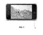
- FIG. 1illustrates a front elevation view of a mobile device with a screen, according to embodiments of the present invention.
- FIG. 2Aillustrates a diagram of a device, according to embodiments of the present invention.
- FIG. 2Billustrates a diagram of a computing device, according to embodiments of the present invention.
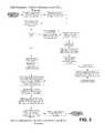
- FIG. 3depicts a flow chart illustrating a data acquisition and device deployment method for an extract transform load process, according to embodiments of the present invention.
- FIG. 4depicts a flow chart illustrating a method for overlaying augmented reality point and line features onto a visual display, according to embodiments of the present invention.
- FIG. 5illustrates a menu screen view, according to embodiments of the present invention.
- FIG. 6illustrates a demonstration screen view, according to embodiments of the present invention.
- FIG. 7illustrates a top plan view of a field of view diagram in an X-Z plane, according to embodiments of the present invention.
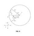
- FIG. 8illustrates a side elevation view of a field of view diagram in a Y-Z plane, according to embodiments of the present invention.
- FIG. 9illustrates a front elevation view of a screen, according to embodiments of the present invention.
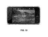
- FIG. 10illustrates a front elevation view of a simulated augmented reality point feature display, according to embodiments of the present invention.
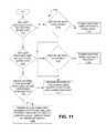
- FIG. 11depicts a flow chart illustrating a method for determining how to visually render a line feature, according to embodiments of the present invention.
- FIG. 12illustrates a spherical frame of reference, according to embodiments of the present invention.
- FIG. 13illustrates a simulated screen shot showing a point feature represented by rectangular overlay, centered on the X-Y origin of the screen, according to embodiments of the present invention.
- FIG. 14illustrates a simulated screen shot showing a line feature, according to embodiments of the present invention.
- FIG. 15illustrates a screen shot showing a ski lift run feature, according to embodiments of the present invention.
- FIG. 16illustrates a screen shot showing two ski lift run features, according to embodiments of the present invention.
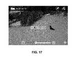
- FIG. 17illustrates a screen shot showing a ski lift run feature, according to embodiments of the present invention.
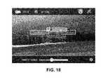
- FIG. 18illustrates a screen shot showing a lodge, ski run, and two ski lift features, according to embodiments of the present invention.
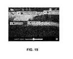
- FIG. 19illustrates a screen shot showing four ski run features, according to embodiments of the present invention.
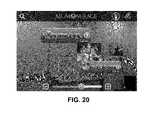
- FIG. 20illustrates a screen shot showing a video clip feature, according to embodiments of the present invention.
- FIG. 21illustrates an augmented reality video overlay process, according to embodiments of the present invention.
- FIG. 1illustrates a front view of a device 100 , such as a mobile device.
- the mobile devicecan be, for example, an Apple iPhone® or iPhone 3G®, or other mobile phone or device, including but not limited to a personal navigation device, a GPS device, a phone, a texting device, a music player, or a video game device.
- FIG. 2is a diagram illustrating various devices that may be included with or operate with device 100 .
- Device 100includes a computing device 212 communicably coupled to a display device 210 , according to embodiments of the present invention.
- Display device 210may be a screen, for example a touch-screen, for displaying visual information to a user.
- Device 100also includes a camera 208 communicably coupled to the computing device 212 , according to embodiments of the present invention.
- Camera 208may be an imaging device and/or video device, such as, for example, a digital camera or digital video camera that captures images and communicates the images to the computing device 212 , which may then process the images and/or display them on the display device 210 , according to embodiments of the present invention.
- communicably coupledis used in its broadest sense to refer to any coupling whereby information may be passed.
- communicably coupledincludes electrically coupled by, for example, a wire; optically coupled by, for example, an optical cable; and/or wirelessly coupled by, for example, a radio frequency or other transmission media.
- “Communicably coupled”also includes, for example, indirect coupling, such as through a network, or direct coupling.
- the device 100may also include a positioning system 202 communicably coupled to the computing device 212 , according to embodiments of the present invention.
- the positioning system 202may be, for example, a global positioning system (“GPS”) configured to receive satellite signals and, based on the signals, determine three-dimensional coordinates for location upon the earth's surface and transmit such location information to the computing device 212 , according to embodiments of the present invention.
- GPSglobal positioning system
- the device 100may also include a compass device 204 communicably coupled to the computing device 212 .
- Compass 204may be an electronic and/or conventional compass configured to measure and/or sense an angle with respect to a “magnetic North” field to determine the device's 100 azimuthal orientation and transmit such orientation information to the computing device 212 , according to embodiments of the present invention.
- the device 100may further include an accelerometer 206 or other similar device communicably coupled to the computing device 212 .
- Accelerometer 206senses and/or measures acceleration and can determine the device's 100 inclination angle with respect to a gravitational force and transmit such inclination angle information to the computing device 212 , according to embodiments of the present invention.
- FIG. 2Billustrates an example of a computer system 212 with which embodiments of the present invention may be utilized.
- the computer systemincludes a bus 301 , at least one processor 302 , at least one communication port 303 , a main memory 304 , a removable storage media 305 , a read only memory 306 , and a mass storage 307 .
- Processor(s) 302can be any known processor, such as, but not limited to, an Intel® Itanium® or Itanium 2® processor(s), or AMD® Opteron® or Athlon MP® processor(s), or Motorola® lines of processors.
- Communication port(s) 303can be any of an RS-232 port for use with a modem based dialup connection, a 10/100 Ethernet port, or a Gigabit port using copper or fiber, for example.
- Communication port(s) 303may be chosen depending on a network such a Local Area Network (LAN), Wide Area Network (WAN), or any network to which the computer system 212 connects, including a wireless network, for example.
- LANLocal Area Network
- WANWide Area Network
- wireless networkfor example.
- Main memory 304can be Random Access Memory (RAM), or any other dynamic storage device(s) commonly known to one of ordinary skill in the art.
- Read only memory 306can be any static storage device(s) such as Programmable Read Only Memory (PROM) chips for storing static information such as instructions for processor 302 , for example.
- PROMProgrammable Read Only Memory
- Mass storage 307can be used to store information and instructions.
- hard diskssuch as the Adaptec® family of SCSI drives, an optical disc, an array of disks such as RAID (e.g. the Adaptec family of RAID drives), or any other mass storage devices may be used, for example.
- Bus 301communicably couples processor(s) 302 with the other memory, storage and communication blocks.
- Bus 301can be a PCI/PCI-X or SCSI based system bus depending on the storage devices used, for example.
- Removable storage media 305can be any kind of external hard-drives, floppy drives, flash drives, IOMEGA® Zip Drives, Compact Disc-Read Only Memory (CD-ROM), Compact Disc-Re-Writable (CD-RW), or Digital Video Disk-Read Only Memory (DVD-ROM), for example.
- CD-ROMCompact Disc-Read Only Memory
- CD-RWCompact Disc-Re-Writable
- DVD-ROMDigital Video Disk-Read Only Memory
- Embodiments of the present inventiondisplay data about features based on the location of those features, and the location and orientation of the device 100 .
- the device 100has access to a three-dimensional spatial database that relates features to three-dimensional coordinates, according to embodiments of the present invention.
- a spatial databasemay be stored on device 100 , for example in read only memory 306 , mass storage device 307 , and/or removable storage media 305 .
- the spatial databasemay also be stored remotely from the device 100 , such as on a satellite computing device or server, that may be accessed remotely by device 100 through its communication port(s) 303 , according to embodiments of the present invention.
- spatial vector datae.g. points, lines and areas
- GMLGeographic Markup Language
- DXFData Exchange Format
- ESRIEnvironmental Science Research Institute
- the spatial data filedefines spatial features in a common Spatial Reference System, e.g. latitude and longitude, Universal Transverse Mercator (UTM), and the like, corresponding to a ground surface of the earth or a portion thereof.
- the spatial data filemay correspond to, or may be trimmed to correspond to, a particular geographic location or geo-political boundary.
- the spatial data filemay correspond to the area of a ski resort (and surrounding areas), according to embodiments of the present invention.
- feature datais extracted from the source data file, transformed to match real world features of interest and then loaded into a spatially enabled central Relational Database Management System (RDBMS) for storage.
- RDBMScentral Relational Database Management System
- ETLExtract Transform and Load
- the source datais augmented with additional information from other commercially and/or freely available sources, for example elevation data, and then pre-processed in order to identify salient spatial feature information used to visualize complex three-dimensional spatial features in an augmented reality environment, for example, a feature heading direction indicator.
- This pre-processingincludes, but is not limited to, deriving feature directional heading, elevation changes, slope angle, and combined feature boundary areas, for example in the manner illustrated in FIG. 3 .
- Additional attribute informationmay then be added to features in order to support functionality in the augmented reality application, for example, a feature in the database may contain a column defining the a point location (for example, by latitude and longitude), and a second column defining elevation. Additional columns may be added to include information about a feature, such as, for example, a textual name, description, altitude, slope angle and/or relative heading. Processed data is then extracted from the central spatial repository and exported directly without transformation to a lightweight spatially enabled RDBMS for deployment to the device 100 , according to embodiments of the present invention.
- Point featuresmay include, for example, facilities or buildings, equipment location, a trailhead, a start point, or an end point. Two or more point features may be associated in the three-dimensional spatial database, for example with a unique shared identifier.
- Linear and area featuresdefined through simple coordinate strings, or more complex spatial algorithms, may be used to represent complex features.
- Non-limiting examples of line featuresinclude trails, roads, ski runs, ski lift paths, equipment routes, and elevation lines, according to embodiments of the present invention.
- Non-limiting examples of area featuresinclude boundaries depicting demarcation by political administration, ownership, usage, coverage, and operations, according to embodiments of the present invention.
- the storage of spatial features and subsequent analysis of spatial relationships between stored features using common spatial operatorspermits the computer 212 to display on the display device 210 information relating to a three-dimensional position of features relative to the current location of the computing device 100 .
- the spatial databasemay include (in addition to the position information) information about the type of facility (e.g. lodge, ski lift, first aid/ski patrol, restaurant, trailhead), hours of operation, activities (e.g. terrain parks or special areas) and/or the amenities available (e.g. restrooms, restaurants, first aid, retail).
- the spatial databasemay include information about skill designation or difficulty (e.g. green, blue, black) and heading.
- the three-dimensional spatial databasemay be dynamically updateable in real time; for example, a data field in the spatial database associated with a ski lift feature may indicate wait time for boarding the ski lift (e.g. number of minutes or red/yellow/green) based on social-based movement data collected remotely from one or more other devices.
- the three-dimensional spatial databaseonce created, may be stored on the device 100 as described above, and may be referred to as a map, according to embodiments of the present invention.
- the device 100may include or have access to multiple maps corresponding to different geographic locations and/or types of activity or use, according to embodiments of the present invention.
- the following open source toolsmay be used in the development of the extract transform load process, for example the process described with respect to FIG. 3 : SharpMap 2.0 and ADO.NET 2.0 SqLite Data Provider 1.0.65 according to embodiments of the present invention.
- FIG. 4depicts a flow chart 400 illustrating a method for determining device 100 location and orientation and displaying features on the device 100 , according to embodiments of the present invention.
- the steps illustrated in flow chart 400may be performed by the processor 302 of computing device 212 , according to embodiments of the present invention.
- the processor instructionsare written in the Objective C language and the database is accessed in SQL.
- the device 100 locationmay be determined (block 402 ) by the GPS 202 , according to embodiments of the present invention.
- the GPS 202transmits location information to the computing device 212 , which may include three-dimensional location information such as, for example, latitude, longitude, and elevation, according to embodiments of the present invention.
- a determinationis made about whether the location of the device 100 is within the boundaries of a map or spatial database (block 404 ).
- the device 100 display screen 210may display an alternative menu structure (block 406 ).
- An example of such an alternative menu structureis illustrated in the display of FIG. 5 , which offers the user a selection between a “my maps” selection 502 and a “demo” selection 504 . Selecting the “my maps” selection 502 takes the user to a screen that shows the user the maps installed on the device 100 and/or offers new maps for purchase or acquisition by the user, according to embodiments of the present invention.
- Selecting the demo selection 504takes the user to a demonstration screen that permits the user to experience the augmented reality view when not at one of the locations supported by a map. For example, the user is taken to a screen similar to that displayed in FIG. 6 , which lists available maps and/or locations selectable by the user for demonstration.
- the device orientationis determined (block 408 ).
- the processor 302may read compass data and/or accelerometer data received and stored from the compass 204 and accelerometer 206 to determine the azimuth and inclination angles. Because the position of the screen/display 210 is often fixed or otherwise known with respect to the camera 208 , GPS 202 , compass 204 , and/or accelerometer 206 , the orientation of the camera 208 view may be determined in three-dimensional polar coordinates, according to embodiments of the present invention.
- a feature rangemay be queried (block 410 ).
- the devicemay generate a “preferences screen” that allows the user to set filters for point features to display (e.g. run, lift, facility, activity, all) and run type display (e.g. green, blue, black, all) and also set search radius, according to embodiments of the present invention.
- the feature range(e.g. search radius) is a distance from the device 100 ; features located within the feature range are displayed on the device 100 , while features outside of the feature range are not displayed on the device 100 .
- the feature rangemay be forty meters, fifty meters, sixty meters, one hundred meters, two hundred meters, one kilometer, and/or any incremental distance.
- the feature rangemay be preset and/or stored on the device 100 and queried by the processor 302 .
- the device 100may prompt the user to enter a desired feature range.
- the device 100may calculate a field of view based on the feature range and the viewing range of the camera 208 .
- the field of viewis a volume extending radially from the device 100 between the upper, lower, and side extents of the camera's viewing range, and bounded by the sphere defined by the distance of the feature range measured from the device 100 position, according to embodiments of the present invention.
- the device 100determines which features in the three-dimensional spatial database intersect the field of view volume (block 412 ). These intersecting features may be flagged for display on the device 100 .
- the device 100next determines how the flagged features are to be displayed, and displays them on the device 100 (block 414 ), according to embodiments of the present invention.
- FIGS. 7-9illustrate how the intersection of the field of view and the features are determined, and how the mapping of the features onto the display is accomplished, according to embodiments of the present invention.
- FIG. 7illustrates a view along the Y axis of a field of view of device 100 .
- the device 100 locationis at the origin O, and the viewing angle of the camera 208 lens extends from a maximum extent 702 to a maximum extent 704 ; in other words, the viewing angle of the camera 208 is angle 708 .
- the center of the viewing angleis indicated by segment 700 ; segment 700 extends along a line from the center of the camera 208 perpendicularly to the imaging surface of the camera 208 , along the Z axis.
- the X, Y, and Z axesare a graphical frame of reference with respect to the origin O (e.g. the device 100 location).
- the length of segment 700 between point O and point 706corresponds to the feature range distance (which may be specified by the user).
- the field of view of the device 100includes the volume between the maximum extents 702 , 704 and within the feature range distance from point O; in other words, the field of view of the device 100 at point O is represented by a pie shape formed by extents 702 , 704 and length of segment 700 in FIG. 7 , according to embodiments of the present invention.
- the device 100determines which features intersect the field of view of the device 100 .
- FIG. 7illustrates various point features A, B, C, and D contained within the spatial database, whose three-dimensional positions are defined by the spatial database.
- the computing device 212determines the location of segment 700 and/or extents 702 , 704 with respect to the three-dimensional spatial database points.
- the computing device 212queries each point feature A, B, C, D and uses geometric calculations (e.g. trigonometric and/or triangulation techniques) to determine whether the point feature is within the field of view.
- the computing device 212determines that the distance between O and B is greater than the feature range (e.g. greater than the distance between O and point 706 ), and therefore that point feature B lies outside of the field of view of the device 100 .
- the computing device 212makes a determination for points C and D, the computing device 212 determines that an angle between segment 700 and segment OC is greater than angle 712 and an angle between segment 700 and segment OD is greater than angle 710 , and therefore that such point features C and D lie outside of the field of view of the device 100 , according to embodiments of the present invention.
- the computing device 212determines that the length of segment 714 is shorter than the feature range (e.g. shorter than the distance between O and point 706 ), and also that angle 716 is less than angle 712 . Before the computing device 212 flags the point feature A as being within the field of view, the computing device 212 must perform similar checks to ensure that point feature A also falls within the viewing angle and feature range of the device 100 in the Z-Y plane, as illustrated in FIG. 8 .
- FIG. 8illustrates a view along the X axis (in the Z-Y plane) of a field of view of device 100 .
- the device 100 locationis at the origin O, and the viewing angle of the camera 208 lens extends from a maximum extent 802 to a maximum extent 804 ; in other words, the viewing angle of the camera 208 is angle 808 .
- the center of the viewing angleis indicated by segment 700 ; segment 700 extends along a line from the center of the camera 208 perpendicularly to the imaging surface of the camera 208 , along the Z axis.
- the X, Y, and Z axesare a graphical frame of reference with respect to the origin O (e.g. the device 100 location).
- the length of segment 700 between point O and point 706corresponds to the feature range distance (which may be specified by the user).
- the field of view of the device 100includes the volume between the maximum extents 802 , 804 and within the feature range distance from point O; in other words, the field of view of the device 100 at point O is represented by a pie shape formed by extents 802 , 804 and length of segment 700 in FIG. 8 , according to embodiments of the present invention.
- the computing device 212determines that the length of segment 714 is shorter than the feature range (e.g. shorter than the distance between O and point 706 ), and also that angle 816 is less than angle 810 . Because point A falls within the projection of the field of view in both the X-Z ( FIG. 7 ) and Y-Z ( FIG. 8 ) planes, the computing device 212 flags or otherwise identifies point feature A as a feature that should be displayed on the display device 210 , according to embodiments of the present invention.
- point Bfalls within the field of view projection in the Y-Z plane, it does not fall within the field of view volume, as evidenced by the fact that it does not fall within the field of view projection in the X-Z plane; thus, the computing device 212 determines that point B should not be displayed on the display device.
- FIG. 9illustrates an exemplary screen 900 , which may be part of display device 210 .
- a rectangular screen 900is shown, and the center of the rectangular screen 900 is at origin point O, and the screen 900 (and camera 208 ) are pointed along the Z axis.
- the screenincludes top edge 902 , bottom edge 904 , left edge 906 , and right edge 908 .
- rotating the camera 208 clockwise or counter-clockwise in the view of FIG. 7turns the camera right and left with respect to the horizon
- rotating the camera 208 clockwise or counterclockwise in the view of FIG. 8rotates the inclination angle up and down with respect to the horizon, according to embodiments of the present invention.
- computing device 212determines where on screen 900 to display point A.
- the X value of the displayed location of Ais determined by angle 716
- the Y value of the displayed location of Ais determined by angle 816 .
- the ratio of the number of pixels between origin O and point A along the X direction to the total number of pixels between origin O and edge 908is equal to the ratio of angle 716 to angle 712 , according to embodiments of the present invention.
- the ratio of the number of pixels between origin O and point A along the Y direction to the total number of pixels between origin O and edge 904is equal to the ratio of angle 816 to angle 810 , according to embodiments of the present invention.
- the screen 900may include 480 pixels along the X direction (e.g. length of edges 902 , 904 ), and 320 pixels in the Y direction (e.g. length of edges 906 , 908 ). If angle 716 is exactly half of angle 712 , and if angle 816 is exactly half of angle 810 , then point A will be located 240 pixels in the X direction from point O toward edge 908 , and 160 pixels in the Y direction from point O toward edge 904 . In addition to or instead of this procedure for mapping the three-dimensional location of points onto a two-dimensional screen, other mapping procedures may be used.
- point feature Ais overlaid on the display of screen 900 onto the real-time or substantially real-time video view of the camera 204 , such that the user sees point A in the visual context of the surrounding physical environment. For example, if point A is the start point of a ski run, the user might see top of a hill in the vicinity of point A.
- FIG. 10illustrates an example of a simulated screen shot showing three different point features displayed over a backdrop camera picture of the surrounding physical environment.
- the top of the screen displaymay include an identification of the resort, map name, location, weather, snowfall, ski conditions, compass orientation, wind direction, and/or the like, according to embodiments of the present invention. Selecting one of the displayed point features presents a “Detail View.” For a ski resort map, clicking on a “run” point feature may display the run name, skill level, and length; clicking on a “lift” point feature may display the lift name, the type (e.g.
- a “facility” point featuremay display the facility name, amenities (e.g. restrooms, ski patrol, lessons, food, etc.), and hours of operation, according to embodiments of the present invention.
- amenitiese.g. restrooms, ski patrol, lessons, food, etc.
- FIG. 11depicts a flow chart 1100 illustrating a method for determining how to display a line feature on display device 210 (e.g. screen 900 ), according to embodiments of the present invention.
- the line featuremay be, for example, two points defined in the spatial database corresponding to a start point and end point of a ski run.
- a determinationis made about whether any line features start, but not end, within the field of view (block 1102 ). If yes, then another determination is made about whether the device 100 is on or by the start point (block 1110 ).
- the “or by” limitationmay be a predefined distance, for example. If yes, then the line feature is rendered on the screen as a point using the line feature's start point (block 1116 ). If the determination of block 1110 is negative, then the line feature is rendered as two points using a highest start point and a lowest end point (block 1114 ).
- the line featureis rendered as two points using a highest start point and a lowest end point (block 1114 ). If not, then the line feature is rendered as a line using the first segment start point and the last segment end point (block 1108 ), according to embodiments of the present invention.
- the device 100renders the point feature on the display screen 900 at the current elevation of the device 100 rather than at the elevation of the point feature. This helps to avoid any confusion by the user who is “just on top of” or “just below” a point feature, but whose camera view does not include the actual elevation of the point feature.
- blocks 408 , 410 , 412 , and 414 of flow chart 400 and the blocks of flow chart 1100are repeated periodically to refresh the display device 210 to reflect the correct features corresponding with the physical camera view.
- the calculationsare repeated at least every twentieth of a second.
- the refresh rateis higher or lower.
- the following software codeillustrates an example of a routine for determining whether a line feature is within the field of view and establishing an X coordinate for the feature rendering, according to embodiments of the present invention.
- This routineis similar to that described with respect to FIG. 11 , according to embodiments of the present invention.
- “leftAzimuth”is the heading boundary on the left side of the viewing device 210 , corresponding to reference 702 in FIG. 7 ;
- “centerAzimuth”is the heading of the center of the viewer, corresponding to segment 700 in FIG. 7 ;
- “rightAzimuth”is the heading boundary of the right side of the viewer, corresponding to reference 704 in FIG. 7 ;
- coordinate.Azimuthis the start heading of the line coordinate;
- “coordinate.EndAzimuth”is the end heading of the line, according to embodiments of the present invention.
- FIG. 12illustrates how computing device 212 generates overlays on three dimensions by considering a sphere generated using the user's current position and a search radius (e.g. feature range).
- Point featuresare mapped within the sphere and translated to two dimensional geometry as single X, Y coordinates on an azimuth (heading) from the current position, as illustrated in FIGS. 7 and 8 .
- Line featuresare processed as two points of intersection to the sphere and a segment in between. The end points of the line segments are rendered similar to single points and the line segment is displayed by taking into account the azimuths of the intersection points, according to embodiments of the present invention.
- FIG. 13illustrates a simulated screen shot showing a start point, end point, or point of interest point (e.g. a point feature) represented by rectangular overlay, centered on the X-Y origin of the screen.
- a start point, end point, or point of interest pointe.g. a point feature
- FIG. 14illustrates a simulated screen shot showing a line feature.
- the line featureis displayed with perspective on the relevant side of the display.
- a center overlayis displayed tracking along that feature until a point is encountered.
- the diagram belowshows the point perspectives 1404 , 1406 and center overlay 1402 all on one screen, according to embodiments of the present invention.
- the spatial databaseis created with and is interacted with (e.g. queried, manipulated, projected, imported, exported) using the SpatiaLite 2.3.1 software.
- SpatiaLite ArchitectureSpatiaLite C API Reference, SpatiaLite Manual, SpatiaLite tutorial, and ADO.NET 2.0/3.5 SQLite Data Provider ReadMe file.
- SpatiaLite softwarethe following is an example of a point feature query to the spatial database:
- the usermay make a selection on the display that causes the processor to switch the display to a two-dimensional flat map mode which displays the current location of the device 100 .
- the device 100offers routing instructions from one point to another. For example, the device 100 suggests the shortest route between two points, the quickest or easiest way down a route, the most groomed ski run.
- the device 100permits users to make restaurant reservations after selecting a restaurant point feature.
- a usercan tag or otherwise mark the location of a particular spot, such as a parking spot, locker, start location, restaurant, and show the spot in the augmented reality/feature overlay view and/or a two dimensional map view.
- the usercan tag or otherwise locate or track (e.g. in three-dimensional overlay view) mobile elements such as, for example, friends and children.
- FIGS. 15-19illustrate screen shots showing various features overlaid onto actual camera views of a ski resort landscape, according to embodiments of the present invention.
- FIG. 15illustrates a view corresponding to the user standing on a ski run called “International.” This view corresponds generally to the rendering described with respect to block 1114 of FIG. 11 , according to embodiments of the present invention.
- the useris standing on or near (e.g. within fifty meters or other preselected criteria) the ski run “International.”
- the box 1502 containing the feature description “International”is placed at the highest start point and lowest end point of the ski run feature (such that if the user turned around, the user would see the feature box at the highest end point of the run within the field of view.
- other visual indicatorssuch as color indicators, may be used to indicate the status of features with respect to the user. For example, a feature name may appear in yellow if the user is on or near the feature, while a feature name may appear in white if the user is not on or near it but it intersects the user's field of view, according to embodiments of the present invention.
- the feature rendering in FIG. 15further displays a heading indicator 1506 in the form of a black arrow, which indicates that the ski run “International” continues from the location of the box 1502 over the ridge in the direction indicated by arrow 1506 .
- FIG. 15also illustrates a slider bar input 1504 which may be slid between “+” and “ ⁇ ” by the user to indicate the user's selected feature range (e.g. distance from the user of the field of view within which features will be displayed). For example, sliding the bar closer to the “ ⁇ ” indicator will display features that are further and further away from the user.
- a sizing algorithmis employed to make the size of the rendered feature box 1502 proportional to the distance between the device 100 and the displayed feature location.
- FIG. 16illustrates a screen display showing two ski run features.
- the useris standing on or near a ski run feature called “Gitalong Road,” of which the lowest end point in the field of view is displayed along with a heading indicator indicating that “Gitalong Road” continues down and to the right of the displayed end point feature location, similar to block 1114 of FIG. 11 .
- FIG. 16also displays a ski run called “Bear Tree” which the user is not on or near, but which starts at the feature location shown in FIG. 16 and continues in the direction of the heading indicator, similar to the rendering described with respect to block 1108 of FIG. 11 , according to embodiments of the present invention.
- FIG. 17illustrates a screen display showing a ski run called “Gitalong Road” which, in the display, traverses the user's view (from the top right of the screen across to the bottom left of the screen). Because the user is not on the ski run or near its start or end point, the ski run feature is displayed as described with respect to block 1108 of FIG. 11 . In other words, the feature indicator box for “Gitalong Road” is displayed in the center of the display with a heading indicator showing that the ski run continues in the direction indicated by the arrow. If the user were to rotate the device 100 to the right of the view shown in FIG. 17 , the heading arrow would rotate counter-clockwise as the feature display updated. Similarly, if the user were to rotate the device 100 to the left in of the view shown in FIG. 17 , the heading arrow would rotate clockwise as the feature display updated, according to embodiments of the present invention.
- FIG. 18illustrates a screen display showing two ski lift features, a ski run feature, and a point feature, according to embodiments of the present invention.
- the point feature “Lionshead”is shown, for example in a different color, indicating the point location of a lodge or other building with a symbol indicating that food is served there, according to embodiments of the present invention.
- the start point of the ski run “Born Free”is shown, as well as the lift locations (start points) for two ski lifts.
- FIG. 19illustrates a screen shot showing multiple ski run features within the field of view, according to embodiments of the present invention.
- FIG. 20illustrates a screen shot showing a video clip feature, according to embodiments of the present invention.
- a video clipis overlayed onto an actual image in a fashion similar to that described above for a point feature, according to embodiments of the present invention.
- Including video clips in augmented reality overlayadds an additional level of information capability.
- a video about Elvisis played corresponding to a location of a particular Elvis landmark on the screen, when such landmark is within the field of view, according to embodiments of the present invention.
- the video clipcontinues to play, although its position on the screen may change so that it continues to correspond to the location of the corresponding point feature within the field of view, according to embodiments of the present invention.
- Additional video clip features or other point or line featuresmay be displayed when they are within a certain customizable distance range of the device and/or when they are not present in the current field of view, for example with a box with a still image, a textual description, and an arrow pointing in the direction in which the device should be rotated in order to bring the other feature within the field of view, according to embodiments of the present invention.
- the Evel Knievel fountainis to the right about one mile away, while the Dunes implosion is to the right about two miles away, according to embodiments of the present invention.
- FIG. 21illustrates an augmented reality video overlay process, according to embodiments of the present invention.
- Many mobile devicesfor example the iPhone, are limited to playing media (videos) natively in a full screen (480 ⁇ 240) view.
- a processmay be followed to play video in a smaller size (in one case 120 ⁇ 90) and centered on any given x,y coordinate on the screen. The following steps may be performed to facilitate such a process:
- the original video source for the overlayis acquired, which may be a YouTube Video, QuickTime MOV Video, MPEG-4 Video, and/or the like. Such an original video source need not be associated with a specific file type, frame rate or quality requirement.
- the original source videomay then be converted to an Animated GIF to support further processing.
- Thiscan be accomplished using licensed software packages such as Video Snapshot by Xilisoft, for example.
- frame ratemay be reduced to around 15 fps, which eliminates frames from the source video but still produces desired results.
- an augmented reality overlayincludes a combination of point features, line features, and/or video features, or an ability to display a combination of point features, line features, and/or video features.
Landscapes
- Engineering & Computer Science (AREA)
- Theoretical Computer Science (AREA)
- General Physics & Mathematics (AREA)
- Physics & Mathematics (AREA)
- General Engineering & Computer Science (AREA)
- Multimedia (AREA)
- Databases & Information Systems (AREA)
- Data Mining & Analysis (AREA)
- Library & Information Science (AREA)
- Computer Graphics (AREA)
- Computer Hardware Design (AREA)
- Software Systems (AREA)
- Signal Processing (AREA)
- Processing Or Creating Images (AREA)
Abstract
Description
| if (coordinate.geoType == GeoLine) { |
| //check if we have some part of the line in our view (but not start or end point) | |
| if (coordinate.azimuth < coordinate.endAzimuth) { | |
| // center would be between | |
| result = (centerAzimuth > coordinate.azimuth && centerAzimuth < |
| coordinate.endAzimuth); |
| } |
| // coordinates flipped |
| if (coordinate.endAzimuth < coordinate.azimuth) { |
| // center would be outside | |
| result = (centerAzimuth > coordinate.endAzimuth ∥ centerAzimuth < |
| coordinate.azimuth); |
| } |
| // North (0) is in our view, process if we are past zero - ADD PI to everything to get off of 0 and |
| do easier math! |
| if (leftAzimuth > rightAzimuth) { |
| if (coordinate.azimuth + M_PI < coordinate.endAzimuth + M_PI) { | |
| // center would be between | |
| result = (centerAzimuth + M_PI > coordinate.azimuth + M_PI && centerAzimuth + M_PI |
| < coordinate.endAzimuth + M_PI); |
| } |
| // coordinates flipped |
| if (coordinate.endAzimuth + M_PI < coordinate.azimuth + M_PI) { |
| // center would be outside | |
| result = (centerAzimuth + M_PI > coordinate.endAzimuth + M_PI ∥ centerAzimuth + |
| M_PI < coordinate.azimuth + M_PI); |
| } |
| } |
| if (result == YES) |
| { |
| //NSLog([NSString stringWithFormat:@“LineSegment:%@ A: %f Ae: %f”, coordinate.title, |
| coordinate.azimuth, coordinate.endAzimuth]); |
| // if we are here, default to use center unless it's one of the points |
| pointAzimuth = centerAzimuth; |
| } |
| // if we didn't get a hit on the line, check for start/end |
| if (!result) { |
| // check for start point | |
| result = (coordinate.azimuth > leftAzimuth && coordinate.azimuth < rightAzimuth); | |
| // past 0 | |
| if (leftAzimuth > rightAzimuth) { | |
| result = (coordinate.azimuth < rightAzimuth ∥ coordinate.azimuth > leftAzimuth); |
| } |
| if (result == YES) |
| { |
| //NSLog([NSString stringWithFormat:@“StartA:%@ A:%f Ae:%f”, coordinate.title, |
| coordinate.azimuth, coordinate.endAzimuth]); |
| // leave it, we'll use start point |
| pointAzimuth = coordinate.azimuth; |
| } |
| if (!result) { |
| // if not, check if we are picking up end point | |
| result = (coordinate.endAzimuth > leftAzimuth && coordinate.endAzimuth < |
| rightAzimuth); |
| // past 0 | |
| if(leftAzimuth > rightAzimuth) { | |
| result = (coordinate.endAzimuth < rightAzimuth ∥ coordinate.endAzimuth > leftAzimuth); | |
| } |
| if (result == YES) | |
| { |
| //NSLog([NSString stringWithFormat:@“EndA:%@ A:%f Ae:%f”, coordinate.title, |
| coordinate.azimuth, coordinate.endAzimuth]); |
| // use end point | |
| pointAzimuth = coordinate.endAzimuth; | |
| } |
| } |
| } |
| @“SELECT X(StartPoint(rs.Route)) as StartPointX, ” |
| “Y(StartPoint(rs.Route)) as StartPointY, ” | ||
| “r.Name, rs.Heading, rs.StartAltitude, rs.RunTypeID, | ||
| rt.Description ” | ||
| “FROM RunSegment rs ” | ||
| “JOIN Run r ON rs.RunId = r.RunId ” | ||
| “JOIN RunType rt ON rs.RunTypeID = rt.RunTypeID ” | ||
| “WHERE MBRContains(BuildCircleMBR (%f, %f, %f, 4030), | ||
| StartPoint(rs.Route)) ” | ||
| “AND rs.IsStart = ‘Y’ ” | ||
| “AND r.IsNamed = ‘Y’ ” | ||
| @“SELECT r.RunId, rs.SegmentId, r.Name, rs.RunTypeID, | ||
| rt.Description, ” | ||
| “X(StartPoint(rs.Route)) as StartPointX, ” | ||
| Y(StartPoint(rs.Route)) as StartPointY, ” | ||
| “rs.StartAltitude, ” | ||
| “X(EndPoint(rs.Route)) as EndPointX, ” | ||
| “Y(EndPoint(rs.Route)) as EndPointY, ” | ||
| “rs.EndAltitude, rs.Heading ” | ||
| “FROM RunSegment rs ” | ||
| “JOIN Run r ON rs.RunId = r.RunId ” | ||
| “JOIN RunType rt ON rs.RunTypeID = rt.RunTypeID ” | ||
| “WHERE MBRIntersects(BuildCircleMBR(%f,%f, %f, 4030), | ||
| rs.Route) ” | ||
| “AND r.IsNamed = ‘Y’ ” | ||
| “ORDER BY r.RunId ASC, SegmentId ASC” | ||
- open the animated GIF file;
- retrieve individual frames into an image array by processing byte data of the animated GIF;
- assign Image array to image user control; and
- animate image array of image user control by setting animation duration to the length (in seconds) of the animated GIF.
Claims (21)
Priority Applications (1)
| Application Number | Priority Date | Filing Date | Title |
|---|---|---|---|
| US12/948,631US8730312B2 (en) | 2009-11-17 | 2010-11-17 | Systems and methods for augmented reality |
Applications Claiming Priority (3)
| Application Number | Priority Date | Filing Date | Title |
|---|---|---|---|
| US26188509P | 2009-11-17 | 2009-11-17 | |
| US32264610P | 2010-04-09 | 2010-04-09 | |
| US12/948,631US8730312B2 (en) | 2009-11-17 | 2010-11-17 | Systems and methods for augmented reality |
Publications (2)
| Publication Number | Publication Date |
|---|---|
| US20110141254A1 US20110141254A1 (en) | 2011-06-16 |
| US8730312B2true US8730312B2 (en) | 2014-05-20 |
Family
ID=44059970
Family Applications (1)
| Application Number | Title | Priority Date | Filing Date |
|---|---|---|---|
| US12/948,631Active2031-10-07US8730312B2 (en) | 2009-11-17 | 2010-11-17 | Systems and methods for augmented reality |
Country Status (2)
| Country | Link |
|---|---|
| US (1) | US8730312B2 (en) |
| WO (1) | WO2011063034A1 (en) |
Cited By (10)
| Publication number | Priority date | Publication date | Assignee | Title |
|---|---|---|---|---|
| US20120306855A1 (en)* | 2011-06-03 | 2012-12-06 | Nintendo Co., Ltd. | Storage medium having stored therein display control program, display control apparatus, display control method, and display control system |
| US20130276280A1 (en)* | 2011-11-04 | 2013-10-24 | Nivora Ip B.V. | Method and Device for Aiding in Manual Handling of a Work Piece During Machining |
| US20140002486A1 (en)* | 2012-06-29 | 2014-01-02 | Joshua J. Ratcliff | Enhanced Information Delivery Using a Transparent Display |
| US20140071166A1 (en)* | 2010-06-23 | 2014-03-13 | Google Inc. | Switching Between a First Operational Mode and a Second Operational Mode Using a Natural Motion Gesture |
| US8922590B1 (en) | 2013-10-01 | 2014-12-30 | Myth Innovations, Inc. | Augmented reality interface and method of use |
| US20170289753A1 (en)* | 2016-03-30 | 2017-10-05 | Honeywell International Inc. | Magnetic fingerprinting for proximity-based systems |
| US20190079693A1 (en)* | 2017-09-14 | 2019-03-14 | International Business Machines Corporation | Dynamic data relocation using cloud based ranks |
| US10818093B2 (en) | 2018-05-25 | 2020-10-27 | Tiff's Treats Holdings, Inc. | Apparatus, method, and system for presentation of multimedia content including augmented reality content |
| US10984600B2 (en) | 2018-05-25 | 2021-04-20 | Tiff's Treats Holdings, Inc. | Apparatus, method, and system for presentation of multimedia content including augmented reality content |
| US20240422511A1 (en)* | 2021-11-03 | 2024-12-19 | Interdigital Patent Holdings, Inc. | Methods and apparatus for supporting collaborative extended reality (xr) |
Families Citing this family (70)
| Publication number | Priority date | Publication date | Assignee | Title |
|---|---|---|---|---|
| US9582937B2 (en)* | 2008-01-02 | 2017-02-28 | Nokia Technologies Oy | Method, apparatus and computer program product for displaying an indication of an object within a current field of view |
| US8159363B2 (en)* | 2009-02-16 | 2012-04-17 | Research In Motion Limited | Using gravity to direct a rotatable camera in a handheld electronic device |
| US9488488B2 (en)* | 2010-02-12 | 2016-11-08 | Apple Inc. | Augmented reality maps |
| TW201134181A (en)* | 2010-03-30 | 2011-10-01 | Hon Hai Prec Ind Co Ltd | Portable communication device and method of taking a picture |
| US9135352B2 (en) | 2010-06-03 | 2015-09-15 | Cisco Technology, Inc. | System and method for providing targeted advertising through traffic analysis in a network environment |
| US9361729B2 (en) | 2010-06-17 | 2016-06-07 | Microsoft Technology Licensing, Llc | Techniques to present location information for social networks using augmented reality |
| KR20120004669A (en)* | 2010-07-07 | 2012-01-13 | 삼성전자주식회사 | World time display device and method in portable terminal |
| JP5571498B2 (en)* | 2010-08-09 | 2014-08-13 | Necマグナスコミュニケーションズ株式会社 | Ambient information search device and ambient information search method |
| US8698843B2 (en) | 2010-11-02 | 2014-04-15 | Google Inc. | Range of focus in an augmented reality application |
| US8681178B1 (en)* | 2010-11-02 | 2014-03-25 | Google Inc. | Showing uncertainty in an augmented reality application |
| KR101295712B1 (en)* | 2010-11-22 | 2013-08-16 | 주식회사 팬택 | Apparatus and Method for Providing Augmented Reality User Interface |
| US20120179965A1 (en)* | 2011-01-12 | 2012-07-12 | Whitney Taylor | Gesture-based navigation system for a mobile device |
| TW201248423A (en)* | 2011-05-17 | 2012-12-01 | Ind Tech Res Inst | Localization device and localization method with the assistance of augmented reality |
| US20120295632A1 (en)* | 2011-05-18 | 2012-11-22 | Sony Ericsson Mobile Communications Ab | Indoor map distribution |
| US9277374B2 (en)* | 2011-06-21 | 2016-03-01 | Cisco Technology, Inc. | Delivering wireless information associating to a facility |
| US10242456B2 (en)* | 2011-06-23 | 2019-03-26 | Limitless Computing, Inc. | Digitally encoded marker-based augmented reality (AR) |
| US9498720B2 (en) | 2011-09-30 | 2016-11-22 | Microsoft Technology Licensing, Llc | Sharing games using personal audio/visual apparatus |
| US9285871B2 (en) | 2011-09-30 | 2016-03-15 | Microsoft Technology Licensing, Llc | Personal audio/visual system for providing an adaptable augmented reality environment |
| US20130083008A1 (en)* | 2011-09-30 | 2013-04-04 | Kevin A. Geisner | Enriched experience using personal a/v system |
| WO2013052451A2 (en)* | 2011-10-03 | 2013-04-11 | Avocent | Data center infrastructure management system having real time enhanced reality tablet |
| US8792912B2 (en) | 2011-12-22 | 2014-07-29 | Cisco Technology, Inc. | System and method for providing proximity-based dynamic content in a network environment |
| KR101303166B1 (en)* | 2012-01-26 | 2013-09-09 | 엘지전자 주식회사 | Mobile terminal and photo searching method thereof |
| US9183676B2 (en) | 2012-04-27 | 2015-11-10 | Microsoft Technology Licensing, Llc | Displaying a collision between real and virtual objects |
| US9153073B2 (en)* | 2012-05-23 | 2015-10-06 | Qualcomm Incorporated | Spatially registered augmented video |
| US9395875B2 (en)* | 2012-06-27 | 2016-07-19 | Ebay, Inc. | Systems, methods, and computer program products for navigating through a virtual/augmented reality |
| WO2014003698A1 (en) | 2012-06-29 | 2014-01-03 | Tusaş-Türk Havacilik Ve Uzay Sanayii A.Ş. | An aircraft vision system |
| US9417692B2 (en) | 2012-06-29 | 2016-08-16 | Microsoft Technology Licensing, Llc | Deep augmented reality tags for mixed reality |
| US20140058778A1 (en)* | 2012-08-24 | 2014-02-27 | Vmware, Inc. | Location-aware calendaring |
| GB201216210D0 (en)* | 2012-09-12 | 2012-10-24 | Appeartome Ltd | Augmented reality apparatus and method |
| US10180715B2 (en) | 2012-10-05 | 2019-01-15 | Elwha Llc | Correlating user reaction with at least an aspect associated with an augmentation of an augmented view |
| US10713846B2 (en) | 2012-10-05 | 2020-07-14 | Elwha Llc | Systems and methods for sharing augmentation data |
| US10269179B2 (en) | 2012-10-05 | 2019-04-23 | Elwha Llc | Displaying second augmentations that are based on registered first augmentations |
| US8928695B2 (en) | 2012-10-05 | 2015-01-06 | Elwha Llc | Formatting of one or more persistent augmentations in an augmented view in response to multiple input factors |
| US9141188B2 (en) | 2012-10-05 | 2015-09-22 | Elwha Llc | Presenting an augmented view in response to acquisition of data inferring user activity |
| US9111383B2 (en) | 2012-10-05 | 2015-08-18 | Elwha Llc | Systems and methods for obtaining and using augmentation data and for sharing usage data |
| US9077647B2 (en) | 2012-10-05 | 2015-07-07 | Elwha Llc | Correlating user reactions with augmentations displayed through augmented views |
| US9030495B2 (en) | 2012-11-21 | 2015-05-12 | Microsoft Technology Licensing, Llc | Augmented reality help |
| CN103105993B (en)* | 2013-01-25 | 2015-05-20 | 腾讯科技(深圳)有限公司 | Method and system for realizing interaction based on augmented reality technology |
| US9092818B2 (en) | 2013-01-31 | 2015-07-28 | Wal-Mart Stores, Inc. | Method and system for answering a query from a consumer in a retail store |
| CN104007889B (en)* | 2013-02-27 | 2018-03-27 | 联想(北京)有限公司 | A kind of feedback method and electronic equipment |
| US10109075B2 (en) | 2013-03-15 | 2018-10-23 | Elwha Llc | Temporal element restoration in augmented reality systems |
| US9639964B2 (en) | 2013-03-15 | 2017-05-02 | Elwha Llc | Dynamically preserving scene elements in augmented reality systems |
| US20140267411A1 (en)* | 2013-03-15 | 2014-09-18 | Elwha Llc | Indicating observation or visibility patterns in augmented reality systems |
| US10025486B2 (en) | 2013-03-15 | 2018-07-17 | Elwha Llc | Cross-reality select, drag, and drop for augmented reality systems |
| WO2014162824A1 (en)* | 2013-04-04 | 2014-10-09 | ソニー株式会社 | Display control device, display control method and program |
| KR102165444B1 (en)* | 2013-08-28 | 2020-10-14 | 엘지전자 주식회사 | Apparatus and Method for Portable Device displaying Augmented Reality image |
| US20160179842A1 (en)* | 2014-12-22 | 2016-06-23 | Geovector Corp. | Computerized Search Dependant on Spatial States |
| US10192359B2 (en) | 2014-01-31 | 2019-01-29 | Empire Technology Development, Llc | Subject selected augmented reality skin |
| US9990772B2 (en) | 2014-01-31 | 2018-06-05 | Empire Technology Development Llc | Augmented reality skin evaluation |
| KR101827550B1 (en) | 2014-01-31 | 2018-02-08 | 엠파이어 테크놀로지 디벨롭먼트 엘엘씨 | Augmented reality skin manager |
| KR101821982B1 (en) | 2014-01-31 | 2018-01-25 | 엠파이어 테크놀로지 디벨롭먼트 엘엘씨 | Evaluation of augmented reality skins |
| GB201404990D0 (en) | 2014-03-20 | 2014-05-07 | Appeartome Ltd | Augmented reality apparatus and method |
| CN104199640B (en)* | 2014-05-27 | 2017-05-10 | 小米科技有限责任公司 | Direction measurement method and device and terminal |
| EP3152737A4 (en)* | 2014-06-03 | 2018-01-24 | Jones, Freddy | In-time registration of temporally separated image acquisition |
| US12008697B2 (en) | 2014-06-10 | 2024-06-11 | Ripple, Inc. Of Delaware | Dynamic location based digital element |
| US9619940B1 (en) | 2014-06-10 | 2017-04-11 | Ripple Inc | Spatial filtering trace location |
| US9646418B1 (en) | 2014-06-10 | 2017-05-09 | Ripple Inc | Biasing a rendering location of an augmented reality object |
| US10026226B1 (en) | 2014-06-10 | 2018-07-17 | Ripple Inc | Rendering an augmented reality object |
| US10930038B2 (en)* | 2014-06-10 | 2021-02-23 | Lab Of Misfits Ar, Inc. | Dynamic location based digital element |
| GB201410285D0 (en) | 2014-06-10 | 2014-07-23 | Appeartome Ltd | Augmented reality apparatus and method |
| US9489494B2 (en) | 2014-06-20 | 2016-11-08 | Dunlop Sports Company Limited | Recommendation engine |
| US11334228B1 (en)* | 2015-03-30 | 2022-05-17 | Evernote Corporation | Dynamic targeting of preferred objects in video stream of smartphone camera |
| CN105184825A (en)* | 2015-10-29 | 2015-12-23 | 丽水学院 | Indoor-scene-oriented mobile augmented reality method |
| EP3430591A4 (en)* | 2016-03-16 | 2019-11-27 | ADCOR Magnet Systems, LLC | System for georeferenced, geo-oriented real time video streams |
| US10210767B2 (en)* | 2016-12-13 | 2019-02-19 | Bank Of America Corporation | Real world gamification using augmented reality user devices |
| US10217375B2 (en)* | 2016-12-13 | 2019-02-26 | Bank Of America Corporation | Virtual behavior training using augmented reality user devices |
| CN107656961B (en)* | 2017-08-04 | 2020-03-27 | 阿里巴巴集团控股有限公司 | Information display method and device |
| US10685485B2 (en)* | 2017-11-21 | 2020-06-16 | Google Llc | Navigation in augmented reality environment |
| CN108712362B (en)* | 2018-03-15 | 2021-03-16 | 高新兴科技集团股份有限公司 | A video map engine system |
| CN112865317A (en)* | 2021-01-28 | 2021-05-28 | 深圳供电局有限公司 | Remote virtual control method, device and system for intelligent power station |
Citations (5)
| Publication number | Priority date | Publication date | Assignee | Title |
|---|---|---|---|---|
| US6985240B2 (en)* | 2002-12-23 | 2006-01-10 | International Business Machines Corporation | Method and apparatus for retrieving information about an object of interest to an observer |
| US7116342B2 (en)* | 2003-07-03 | 2006-10-03 | Sportsmedia Technology Corporation | System and method for inserting content into an image sequence |
| US20070024644A1 (en)* | 2005-04-15 | 2007-02-01 | Herman Bailey | Interactive augmented reality system |
| US7398481B2 (en)* | 2002-12-10 | 2008-07-08 | Science Applications International Corporation (Saic) | Virtual environment capture |
| US7916138B2 (en)* | 1993-09-10 | 2011-03-29 | Geovector Corporation | Electro-optic vision systems |
Family Cites Families (3)
| Publication number | Priority date | Publication date | Assignee | Title |
|---|---|---|---|---|
| US6765569B2 (en)* | 2001-03-07 | 2004-07-20 | University Of Southern California | Augmented-reality tool employing scene-feature autocalibration during camera motion |
| US20030012410A1 (en)* | 2001-07-10 | 2003-01-16 | Nassir Navab | Tracking and pose estimation for augmented reality using real features |
| IL169934A (en)* | 2005-07-27 | 2013-02-28 | Rafael Advanced Defense Sys | Real-time geographic information system and method |
- 2010
- 2010-11-17WOPCT/US2010/057096patent/WO2011063034A1/enactiveApplication Filing
- 2010-11-17USUS12/948,631patent/US8730312B2/enactiveActive
Patent Citations (5)
| Publication number | Priority date | Publication date | Assignee | Title |
|---|---|---|---|---|
| US7916138B2 (en)* | 1993-09-10 | 2011-03-29 | Geovector Corporation | Electro-optic vision systems |
| US7398481B2 (en)* | 2002-12-10 | 2008-07-08 | Science Applications International Corporation (Saic) | Virtual environment capture |
| US6985240B2 (en)* | 2002-12-23 | 2006-01-10 | International Business Machines Corporation | Method and apparatus for retrieving information about an object of interest to an observer |
| US7116342B2 (en)* | 2003-07-03 | 2006-10-03 | Sportsmedia Technology Corporation | System and method for inserting content into an image sequence |
| US20070024644A1 (en)* | 2005-04-15 | 2007-02-01 | Herman Bailey | Interactive augmented reality system |
Cited By (20)
| Publication number | Priority date | Publication date | Assignee | Title |
|---|---|---|---|---|
| US20140071166A1 (en)* | 2010-06-23 | 2014-03-13 | Google Inc. | Switching Between a First Operational Mode and a Second Operational Mode Using a Natural Motion Gesture |
| US8922487B2 (en)* | 2010-06-23 | 2014-12-30 | Google Inc. | Switching between a first operational mode and a second operational mode using a natural motion gesture |
| US20120306855A1 (en)* | 2011-06-03 | 2012-12-06 | Nintendo Co., Ltd. | Storage medium having stored therein display control program, display control apparatus, display control method, and display control system |
| US9561571B2 (en)* | 2011-11-04 | 2017-02-07 | Nivora Ip B.V. | Method and device for aiding in manual handling of a work piece during machining |
| US20130276280A1 (en)* | 2011-11-04 | 2013-10-24 | Nivora Ip B.V. | Method and Device for Aiding in Manual Handling of a Work Piece During Machining |
| US20140002486A1 (en)* | 2012-06-29 | 2014-01-02 | Joshua J. Ratcliff | Enhanced Information Delivery Using a Transparent Display |
| US9646522B2 (en)* | 2012-06-29 | 2017-05-09 | Intel Corporation | Enhanced information delivery using a transparent display |
| US11055928B2 (en) | 2013-10-01 | 2021-07-06 | Myth Innovations, Inc. | Augmented reality interface and method of use |
| US8943569B1 (en) | 2013-10-01 | 2015-01-27 | Myth Innovations, Inc. | Wireless server access control system and method |
| US10769853B2 (en) | 2013-10-01 | 2020-09-08 | Myth Innovations, Inc. | Augmented reality interface and method of use |
| US8922590B1 (en) | 2013-10-01 | 2014-12-30 | Myth Innovations, Inc. | Augmented reality interface and method of use |
| US20170289753A1 (en)* | 2016-03-30 | 2017-10-05 | Honeywell International Inc. | Magnetic fingerprinting for proximity-based systems |
| US10182309B2 (en)* | 2016-03-30 | 2019-01-15 | Honeywell International Inc. | Magnetic fingerprinting for proximity-based systems |
| US20190079693A1 (en)* | 2017-09-14 | 2019-03-14 | International Business Machines Corporation | Dynamic data relocation using cloud based ranks |
| US10818093B2 (en) | 2018-05-25 | 2020-10-27 | Tiff's Treats Holdings, Inc. | Apparatus, method, and system for presentation of multimedia content including augmented reality content |
| US10984600B2 (en) | 2018-05-25 | 2021-04-20 | Tiff's Treats Holdings, Inc. | Apparatus, method, and system for presentation of multimedia content including augmented reality content |
| US11494994B2 (en) | 2018-05-25 | 2022-11-08 | Tiff's Treats Holdings, Inc. | Apparatus, method, and system for presentation of multimedia content including augmented reality content |
| US11605205B2 (en) | 2018-05-25 | 2023-03-14 | Tiff's Treats Holdings, Inc. | Apparatus, method, and system for presentation of multimedia content including augmented reality content |
| US12051166B2 (en) | 2018-05-25 | 2024-07-30 | Tiff's Treats Holdings, Inc. | Apparatus, method, and system for presentation of multimedia content including augmented reality content |
| US20240422511A1 (en)* | 2021-11-03 | 2024-12-19 | Interdigital Patent Holdings, Inc. | Methods and apparatus for supporting collaborative extended reality (xr) |
Also Published As
| Publication number | Publication date |
|---|---|
| US20110141254A1 (en) | 2011-06-16 |
| WO2011063034A1 (en) | 2011-05-26 |
Similar Documents
| Publication | Publication Date | Title |
|---|---|---|
| US8730312B2 (en) | Systems and methods for augmented reality | |
| US10929494B2 (en) | Systems and methods for tagging objects for augmented reality | |
| US9984500B2 (en) | Method, system, and computer-readable data storage device for creating and displaying three-dimensional features on an electronic map display | |
| US9280851B2 (en) | Augmented reality system for supplementing and blending data | |
| KR101962394B1 (en) | Prominence-based generation and rendering of map features | |
| US8803917B2 (en) | Computer-implemented system and method for a virtual object rendering based on real world locations and tags | |
| US9625612B2 (en) | Landmark identification from point cloud generated from geographic imagery data | |
| US20130162665A1 (en) | Image view in mapping | |
| US8532924B2 (en) | Method and apparatus for displaying three-dimensional terrain and route guidance | |
| WO2010052558A2 (en) | System and method for the precise integration of virtual objects to interactive panoramic walk-through applications | |
| JP2013507677A (en) | Display method of virtual information in real environment image | |
| US12073601B2 (en) | Determining visual overlap of images by using box embeddings | |
| JP2006091390A (en) | Information display system, information display method, and program for causing computer to execute information display method and information display terminal device | |
| US10964112B2 (en) | Candidate geometry displays for augmented reality | |
| US11461976B2 (en) | Visualization transitions for augmented reality | |
| CN118470233B (en) | Panoramic geographic event scene generation method, device, equipment and storage medium | |
| US10930079B1 (en) | Techniques for displaying augmentations that represent cadastral lines and other near-ground features | |
| Thomas et al. | 3D modeling for mobile augmented reality in unprepared environment | |
| FR2986891A1 (en) | Method for displaying outdoor composite image on screen of mobile terminal e.g. smartphone, involves determining spatial coordinates of portion of elementary image, and assigning coordinates to observation point, to form composite image | |
| Olesk | Vision-based positioning and navigation with 3D maps: concepts and analysis |
Legal Events
| Date | Code | Title | Description |
|---|---|---|---|
| AS | Assignment | Owner name:RTP, LLC, COLORADO Free format text:ASSIGNMENT OF ASSIGNORS INTEREST;ASSIGNORS:ROEBKE, MARK J.;DAVIDSON, ALISTAIR NEIL;REEL/FRAME:025874/0947 Effective date:20110207 | |
| AS | Assignment | Owner name:BANK OF AMERICA, N.A., AS ADMINISTRATIVE AGENT, WA Free format text:NOTICE OF GRANT OF SECURITY INTEREST IN PATENTS;ASSIGNOR:RTP, LLC;REEL/FRAME:027409/0748 Effective date:20111216 | |
| AS | Assignment | Owner name:THE ACTIVE NETWORK, INC., CALIFORNIA Free format text:ASSIGNMENT OF ASSIGNORS INTEREST;ASSIGNOR:RTP, LLC;REEL/FRAME:027685/0551 Effective date:20120209 | |
| AS | Assignment | Owner name:RTP, LLC, CALIFORNIA Free format text:RELEASE BY SECURED PARTY;ASSIGNOR:BANK OF AMERICA, N.A.;REEL/FRAME:031646/0974 Effective date:20131115 Owner name:BANK OF AMERICA, N.A., AS COLLATERAL AGENT, CALIFO Free format text:FIRST LIEN SECURITY AGREEMENT;ASSIGNOR:THE ACTIVE NETWORK INC.;REEL/FRAME:031645/0514 Effective date:20131115 | |
| AS | Assignment | Owner name:BANK OF AMERICA, N.A., AS COLLATERAL AGENT, CALIFO Free format text:SECOND LIEN SECURITY AGREEMENT;ASSIGNOR:THE ACTIVE NETWORK INC.;REEL/FRAME:031664/0835 Effective date:20131115 | |
| STCF | Information on status: patent grant | Free format text:PATENTED CASE | |
| AS | Assignment | Owner name:ACTIVE NETWORK, LLC, CALIFORNIA Free format text:ASSIGNMENT OF ASSIGNORS INTEREST;ASSIGNOR:THE ACTIVE NETWORK, INC.;REEL/FRAME:032803/0562 Effective date:20140430 | |
| AS | Assignment | Owner name:LANYON, INC., TEXAS Free format text:RELEASE OF FIRST LIEN SECURITY INTEREST;ASSIGNOR:BANK OF AMERICA, N.A.;REEL/FRAME:040978/0461 Effective date:20161129 Owner name:LANYON SOLUTIONS, INC.(F/K/A THE ACTIVE NETWORK, I Free format text:RELEASE OF FIRST LIEN SECURITY INTEREST;ASSIGNOR:BANK OF AMERICA, N.A.;REEL/FRAME:040978/0461 Effective date:20161129 | |
| AS | Assignment | Owner name:LANYON SOLUTIONS, INC. (F/K/A THE ACTIVE NETWORK, Free format text:RELEASE OF SECOND LIEN SECURITY INTEREST;ASSIGNOR:BANK OF AMERICA, N.A.;REEL/FRAME:040546/0816 Effective date:20161129 Owner name:LANYON, INC., TEXAS Free format text:RELEASE OF SECOND LIEN SECURITY INTEREST;ASSIGNOR:BANK OF AMERICA, N.A.;REEL/FRAME:040546/0816 Effective date:20161129 | |
| FEPP | Fee payment procedure | Free format text:SURCHARGE FOR LATE PAYMENT, LARGE ENTITY (ORIGINAL EVENT CODE: M1554) | |
| MAFP | Maintenance fee payment | Free format text:PAYMENT OF MAINTENANCE FEE, 4TH YEAR, LARGE ENTITY (ORIGINAL EVENT CODE: M1551) Year of fee payment:4 | |
| AS | Assignment | Owner name:BANK OF AMERICA, N.A., AS ADMINISTRATIVE AGENT, NO Free format text:NOTICE OF GRANT OF SECURITY INTEREST IN PATENTS;ASSIGNOR:ACTIVE NETWORK, LLC;REEL/FRAME:048764/0575 Effective date:20160422 | |
| AS | Assignment | Owner name:XENIAL, INC. (F/K/A HEARTLAND COMMERCE, INC.), GEORGIA Free format text:RELEASE BY SECURED PARTY;ASSIGNOR:BANK OF AMERICA, N.A.;REEL/FRAME:050406/0851 Effective date:20190917 Owner name:HEARTLAND PAYMENT SYSTEMS, LLC, GEORGIA Free format text:RELEASE BY SECURED PARTY;ASSIGNOR:BANK OF AMERICA, N.A.;REEL/FRAME:050406/0851 Effective date:20190917 Owner name:ACTIVE NETWORK, LLC, TEXAS Free format text:RELEASE BY SECURED PARTY;ASSIGNOR:BANK OF AMERICA, N.A.;REEL/FRAME:050406/0851 Effective date:20190917 Owner name:DEBITEK, INC., GEORGIA Free format text:RELEASE BY SECURED PARTY;ASSIGNOR:BANK OF AMERICA, N.A.;REEL/FRAME:050406/0851 Effective date:20190917 Owner name:NUESOFT TECHNOLOGIES INC., UTAH Free format text:RELEASE BY SECURED PARTY;ASSIGNOR:BANK OF AMERICA, N.A.;REEL/FRAME:050406/0851 Effective date:20190917 Owner name:NUEIP, LLC, UTAH Free format text:RELEASE BY SECURED PARTY;ASSIGNOR:BANK OF AMERICA, N.A.;REEL/FRAME:050406/0851 Effective date:20190917 Owner name:ADVANCEDMD, INC., UTAH Free format text:RELEASE BY SECURED PARTY;ASSIGNOR:BANK OF AMERICA, N.A.;REEL/FRAME:050406/0851 Effective date:20190917 Owner name:XENIAL, INC. (F/K/A HEARTLAND COMMERCE, INC.), GEO Free format text:RELEASE BY SECURED PARTY;ASSIGNOR:BANK OF AMERICA, N.A.;REEL/FRAME:050406/0851 Effective date:20190917 Owner name:TOUCHNET INFORMATION SYSTEMS, INC., GEORGIA Free format text:RELEASE BY SECURED PARTY;ASSIGNOR:BANK OF AMERICA, N.A.;REEL/FRAME:050406/0851 Effective date:20190917 Owner name:GLOBAL PAYMENTS INC., GEORGIA Free format text:RELEASE BY SECURED PARTY;ASSIGNOR:BANK OF AMERICA, N.A.;REEL/FRAME:050406/0851 Effective date:20190917 Owner name:NEXTEP SYSTEMS INC., MICHIGAN Free format text:RELEASE BY SECURED PARTY;ASSIGNOR:BANK OF AMERICA, N.A.;REEL/FRAME:050406/0851 Effective date:20190917 | |
| MAFP | Maintenance fee payment | Free format text:PAYMENT OF MAINTENANCE FEE, 8TH YEAR, LARGE ENTITY (ORIGINAL EVENT CODE: M1552); ENTITY STATUS OF PATENT OWNER: LARGE ENTITY Year of fee payment:8 |