US8728092B2 - Stereotactic drive system - Google Patents
Stereotactic drive systemDownload PDFInfo
- Publication number
- US8728092B2 US8728092B2US12/540,558US54055809AUS8728092B2US 8728092 B2US8728092 B2US 8728092B2US 54055809 AUS54055809 AUS 54055809AUS 8728092 B2US8728092 B2US 8728092B2
- Authority
- US
- United States
- Prior art keywords
- spool
- wire
- drive system
- rotatable portion
- mount
- Prior art date
- Legal status (The legal status is an assumption and is not a legal conclusion. Google has not performed a legal analysis and makes no representation as to the accuracy of the status listed.)
- Ceased, expires
Links
Images


Classifications
- G—PHYSICS
- G05—CONTROLLING; REGULATING
- G05G—CONTROL DEVICES OR SYSTEMS INSOFAR AS CHARACTERISED BY MECHANICAL FEATURES ONLY
- G05G1/00—Controlling members, e.g. knobs or handles; Assemblies or arrangements thereof; Indicating position of controlling members
- G05G1/08—Controlling members for hand actuation by rotary movement, e.g. hand wheels
- G05G1/10—Details, e.g. of discs, knobs, wheels or handles
- A—HUMAN NECESSITIES
- A61—MEDICAL OR VETERINARY SCIENCE; HYGIENE
- A61B—DIAGNOSIS; SURGERY; IDENTIFICATION
- A61B17/00—Surgical instruments, devices or methods
- A61B17/34—Trocars; Puncturing needles
- A61B17/3403—Needle locating or guiding means
- A—HUMAN NECESSITIES
- A61—MEDICAL OR VETERINARY SCIENCE; HYGIENE
- A61B—DIAGNOSIS; SURGERY; IDENTIFICATION
- A61B34/00—Computer-aided surgery; Manipulators or robots specially adapted for use in surgery
- A61B34/20—Surgical navigation systems; Devices for tracking or guiding surgical instruments, e.g. for frameless stereotaxis
- A—HUMAN NECESSITIES
- A61—MEDICAL OR VETERINARY SCIENCE; HYGIENE
- A61B—DIAGNOSIS; SURGERY; IDENTIFICATION
- A61B34/00—Computer-aided surgery; Manipulators or robots specially adapted for use in surgery
- A61B34/70—Manipulators specially adapted for use in surgery
- A—HUMAN NECESSITIES
- A61—MEDICAL OR VETERINARY SCIENCE; HYGIENE
- A61B—DIAGNOSIS; SURGERY; IDENTIFICATION
- A61B34/00—Computer-aided surgery; Manipulators or robots specially adapted for use in surgery
- A61B34/70—Manipulators specially adapted for use in surgery
- A61B34/71—Manipulators operated by drive cable mechanisms
- A—HUMAN NECESSITIES
- A61—MEDICAL OR VETERINARY SCIENCE; HYGIENE
- A61B—DIAGNOSIS; SURGERY; IDENTIFICATION
- A61B90/00—Instruments, implements or accessories specially adapted for surgery or diagnosis and not covered by any of the groups A61B1/00 - A61B50/00, e.g. for luxation treatment or for protecting wound edges
- A61B90/10—Instruments, implements or accessories specially adapted for surgery or diagnosis and not covered by any of the groups A61B1/00 - A61B50/00, e.g. for luxation treatment or for protecting wound edges for stereotaxic surgery, e.g. frame-based stereotaxis
- A61B90/11—Instruments, implements or accessories specially adapted for surgery or diagnosis and not covered by any of the groups A61B1/00 - A61B50/00, e.g. for luxation treatment or for protecting wound edges for stereotaxic surgery, e.g. frame-based stereotaxis with guides for needles or instruments, e.g. arcuate slides or ball joints
- A—HUMAN NECESSITIES
- A61—MEDICAL OR VETERINARY SCIENCE; HYGIENE
- A61B—DIAGNOSIS; SURGERY; IDENTIFICATION
- A61B18/00—Surgical instruments, devices or methods for transferring non-mechanical forms of energy to or from the body
- A61B18/18—Surgical instruments, devices or methods for transferring non-mechanical forms of energy to or from the body by applying electromagnetic radiation, e.g. microwaves
- A61B18/20—Surgical instruments, devices or methods for transferring non-mechanical forms of energy to or from the body by applying electromagnetic radiation, e.g. microwaves using laser
- A—HUMAN NECESSITIES
- A61—MEDICAL OR VETERINARY SCIENCE; HYGIENE
- A61B—DIAGNOSIS; SURGERY; IDENTIFICATION
- A61B17/00—Surgical instruments, devices or methods
- A61B17/34—Trocars; Puncturing needles
- A61B17/3403—Needle locating or guiding means
- A61B2017/3405—Needle locating or guiding means using mechanical guide means
- A61B2017/3409—Needle locating or guiding means using mechanical guide means including needle or instrument drives
- A—HUMAN NECESSITIES
- A61—MEDICAL OR VETERINARY SCIENCE; HYGIENE
- A61B—DIAGNOSIS; SURGERY; IDENTIFICATION
- A61B90/00—Instruments, implements or accessories specially adapted for surgery or diagnosis and not covered by any of the groups A61B1/00 - A61B50/00, e.g. for luxation treatment or for protecting wound edges
- A61B90/50—Supports for surgical instruments, e.g. articulated arms
Definitions
- the present inventionrelates generally to control systems. More specifically, the present invention relates to a drive system for controlling the longitudinal movement and rotational position of an elongate member.
- cancerous brain tumorstypically consist of brain tissue with mutated DNA that aggressively grows and displaces or replaces normal brain tissue.
- gliomasThe most common of the primary tumors are known as gliomas, which indicate cancer of the glial cells of the brain. In most instances, primary tumors appear as single masses. However, these single masses can often be quite large, irregularly-shaped, multi-lobed and/or infiltrated into surrounding brain tissue.
- Primary tumorsare generally not diagnosed until the patient experiences symptoms, such as headaches, altered behavior, sensory impairment, or the like. However, by the time the symptoms develop the tumor may already be large and aggressive.
- surgeryinvolves a craniotomy (i.e., removal of a portion of the skull), dissection, and total or partial tumor resection.
- the objectives of surgeryinclude removal or lessening of the number of active malignant cells within the brain, and a reduction in the pain or functional impairment due to the effect of the tumor on adjacent brain structures.
- surgeryis highly invasive and risky.
- surgeryis often only partially effective. In other tumors, the surgery itself may not be feasible, it may risk impairment to the patient, it may not be tolerable by the patient, and/or it may involve significant cost and recovery.
- SRSstereotactic radiosurgery
- SRSis a treatment method by which multiple intersecting beams of radiation are directed at the tumor such that the point of intersection of the beams receives a lethal dose of radiation, while tissue in the path of any single beam remains unharmed.
- SRSis non-invasive and is typically performed as a single outpatient procedure.
- confirmation that the tumor has been killed or neutralizedis often not possible for several months post-treatment.
- high doses of radiationmay be required to kill a tumor, such as in the case of multiple or recurring tumors, it is common for the patient to reach the “toxic threshold” prior to killing all of the tumors, where further radiation is inadvisable.
- heatalso referred to as hyperthermia or thermal therapy
- coagulation necrosis or ablationMalignant tumors, because of their high vascularization and altered DNA, are more susceptible to heat-induced damage than normal tissue.
- energy sourcessuch as laser, microwave, radiofrequency, electric, and ultrasound sources.
- the heat sourcemay be extracorporeal (i.e., outside the body), extrastitial (i.e., outside the tumor), or interstitial (i.e., inside the tumor).
- Interstitial thermal therapyis a process designed to heat and destroy a tumor from within the tumor.
- One advantage of this type of therapyis that the energy is applied directly to the tumor rather than passing through surrounding normal tissue.
- Another advantage of the type of therapyis that the energy deposition is more likely to be extended throughout the entire tumor.
- One exemplary ITT processbegins by inserting an optical fiber into the tumor, wherein the tumor has an element at its “inserted” end that redirects laser light from an exterior source in a direction generally at right angles to the length of the fiber.
- the energy from the laserthus extends into the tissue surrounding the end or tip and effects heating.
- the energyis directed in a beam confined to a relatively shallow angle so that, as the fiber is rotated, the beam also rotates around the axis of the fiber to effect heating of different parts of the tumor at positions around the fiber.
- the fibercan thus be moved longitudinally and rotated to effect heating of the tumor over the full volume of the tumor with the intention of heating the tumor to the required temperature without significantly affecting the surrounding tissue.
- the fiber used in the ITT processmay be controlled and manipulated by a surgeon with little or no guidance apart from the surgeon's knowledge of the anatomy of the patient and the location of the tumor. Therefore, it is difficult for the surgeon to effect a controlled heating which heats the entire tumor to a required level while also minimizing damage to the surrounding tissue.
- the location of tumors and other lesions to be excisedcan be determined using a magnetic resonance imaging system. Although these imaging systems have been helpful to assist the surgeon in determining a location of the tumor to be excised, use of the imaging systems ended once the location of the tumor was mapped out for the surgeon. In particular, previous excision procedures required the removal of the patient from the imaging system prior to commencing treatment. However, movement of the patient, together with the partial excision or coagulation of some of the tissue, can significantly change the location of the tumor to be excised. As a result, any possibility of providing controlled accuracy in the excision is eliminated.
- magnetic resonance imaging systemscan be used by modification of the imaging sequences to determine the temperature of tissue within the image and to determine changes in that temperature over time.
- U.S. Pat. No. 5,284,144(Delannoy) also assigned to U.S. Department of Health and Human Services and issued Feb. 8, 1994, discloses an apparatus for hyperthermia treatment of cancer in which an external, non-invasive heating system is mounted within the coil of a magnetic resonance imaging system.
- the disclosureis speculative and relates to initial experimentation concerning the viability of MRI measurement of temperature in conjunction with an external heating system.
- the disclosure of the patenthas not led to a commercially viable hyperthermic treatment system.
- U.S. Pat. Nos. 5,368,031 and 5,291,890 assigned to General Electricrelate to an MRI controlled heating system in which a point source of heat generates a predetermined heat distribution which is then monitored to ensure that the actual heat distribution follows the predicted heat distribution to obtain an overall heating of the area to be heated. Again this patented arrangement has not led to a commercially viable hyperthermia surgical system.
- U.S. Pat. No. 5,823,941(Shaunnessey), not assigned, and issued Oct. 20, 1998, discloses a specially modified endoscope designed to support an optical fiber.
- the optical fiberemits light energy and may be moved longitudinally and rotated angularly about its axis to direct the energy.
- the deviceis used for excising tumors, and the energy is arranged to be sufficient to effect vaporization of the tissue to be excised.
- the gas formed during the processis removed by suction through the endoscope.
- An image of the tumoris obtained by MRI, which is thereafter used to program a path of movement of the fiber to be taken during the operation. Again, there is no feedback during the procedure to control the movement of the optical fiber, and the operation is wholly dependent upon the initial analysis. This arrangement has not achieved commercial or medical success.
- U.S. Pat. No. 5,454,807(Lennox) assigned to Boston Scientific Corporation and issued Oct. 3, 1995, discloses a device for use in irradiating a tumor with light energy from an optical fiber.
- a cooling fluidis supplied through a conduit within the fiber to apply surface cooling and to prevent surface damage while allowing increased levels of energy to be applied to deeper tissues.
- U.S. Pat. No. 5,785,704assigned to MRC Systems GmbH and issued Jul. 28, 1996, also discloses a particular arrangement of a laser beam and lens for use in irradiation of brain tumors.
- this arrangementuses high speed pulsed laser energy for a photo-disruption effect, but does not disclose methods of feedback control of the energy.
- Focused laser interstitial thermal therapyis the next general refinement of laser-based thermal therapy technologies.
- f-LITTenables precise control over the deposition of heat energy, thereby enabling the physician to contain cell damage exclusively to within a tumor mass of virtually any size and shape.
- the drive systemshould preferably be structured for use with any elongate medical device including, but not limited to, laser probes, catheters, endoscopes, and the like.
- the drive systemshould also preferably be manufactured from materials that make the system MRI-compatible.
- the present inventionsolves the foregoing problems by providing a drive system for controlling movement of an elongate member including a base unit having a first rotatable knob and a second rotatable knob, a follower assembly including a follower slidably coupled to a guide rail, a longitudinal movement wire, and a rotational movement wire.
- the followerincludes a longitudinal movement pulley, a rotational movement pulley, and an alignment element structured to receive an elongate member such that the elongate member is attachable thereto.
- the longitudinal movement wireoperably couples the first rotatable knob to the longitudinal movement pulley such that rotation of the first knob drives the follower in a longitudinal direction along the guide rail.
- the rotational movement wireoperably couples the second rotatable knob to the rotational movement pulley such that rotation of the second knob rotates the alignment element and attached elongate member.
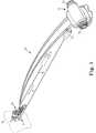
- FIG. 1is a perspective view of one exemplary drive system in accordance with the present invention that includes a commander unit, a follower assembly, and an elongate member coupled to the follower assembly.
- FIG. 2Ais a perspective view of the commander unit and follower assembly of FIG. 1 illustrating rotation of a first knob to cause longitudinal movement of a follower device.
- FIG. 2Bis a perspective view of one exemplary alternative follower assembly in accordance with the present invention.
- FIG. 3is a perspective view of the commander unit and follower assembly of FIG. 1 illustrating rotation of a second knob to cause rotational movement of an alignment device on a proximal end of the follower device.
- FIG. 4is an enlarged perspective view of the commander unit with a commander cover removed to illustrate the internal components of the commander unit.
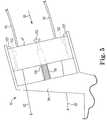
- FIG. 5is a diagram illustrating a side view of a first tension block assembly within the commander unit.
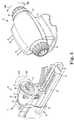
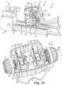
- FIG. 6is an enlarged perspective view of the follower assembly with a portion of the follower device housing removed in order to illustrate the internal components of the follower device.
- FIG. 7is a perspective view of the drive system in accordance with the present invention wherein the follower device is shown in a “neutral” starting position.
- FIG. 8Ais a perspective view of the drive system illustrating operation of the commander unit to drive the follower device longitudinally and in a distal direction.
- FIG. 8Bis a diagram of an underside of the follower assembly illustrating movement of the follower device longitudinally and in the distal direction shown in FIG. 8A .
- FIG. 9Ais a perspective view of the drive system illustrating operation of commander unit to drive the follower device longitudinally and in a proximal direction.
- FIG. 9Bis a diagram of the underside of the follower assembly illustrating movement of the follower device longitudinally and in the proximal direction shown in FIG. 9A .
- FIG. 10is a perspective view of the drive system illustrating operation of the commander unit to rotate the alignment device in a clockwise direction as viewed from a proximal end of the follower device.
- FIG. 11is a perspective view of the drive system illustrating operation of the commander unit to rotate the alignment device in a counterclockwise direction as viewed from the proximal end of the follower device.
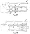
- FIG. 12Ais a diagram illustrating the structure of a first locking device coupled to the commander unit.
- FIG. 12Bis a perspective view of the first locking device illustrating the first knob in an unlocked position.
- the present inventioninvolves a drive system for stereotactic positioning of an elongate member.
- the elongate membermay include, for example, elongate probes, catheters, endoscopes, and the like.
- the drive system of the present inventionmay be used in conjunction with any elongate member requiring precise control in a longitudinal and/or rotational direction.
- the drive system in accordance with the present inventionmay be used to control the precise movement of a laser probe insertable into the skull of a patient for the treatment of tumors.
- the drive systemmay be operated to position a distal end of a probe at precise locations within the tumor through both controlled longitudinal and rotational movement of the probe.
- FIG. 1there is shown a perspective view of one exemplary drive system 10 including commander or base unit 12 , follower assembly 14 , potentiometer assembly 15 having connector 13 , and elongate member 16 coupled to follower assembly 14 .
- commander unit 12has a first knob 18 structured for causing longitudinal movement of elongate member 16 as indicated by arrow L, and a second knob 20 structured for causing rotational movement of elongate member 16 as indicated by arrow R.
- drive system 10may be utilized to control the precise longitudinal and angular position of elongate member 16 relative to or within a particular location or element, such as generic mass M shown in broken lines proximate to follower assembly 14 .
- Potentiometer assembly 15may be operably coupled to follower assembly 14 and configured to provide feedback regarding the longitudinal and angular position of elongate member 16 to a computer system or other processing means through connector 13 .
- An external displaymay be operably coupled to the computer system or processing means in order to display longitudinal and rotational movement of elongate member 16 during operation of drive system 10 .
- a displaymay alternatively be provided on commander unit 12 instead of (or in addition to) the external display as will be appreciated by those skilled in the art.
- the longitudinal movement of elongate member 16may be displayed as a numerical value (relative to a “zero” reference point) having any suitable unit, such as in millimeters.
- the rotational movement of elongate member 16may be displayed in any suitable manner, such as by a number in a range between about +180 degrees and about ⁇ 180 degrees surrounding a “zero” reference point.
- the longitudinal and rotational movement of elongate member 16may be displayed in numerous other ways and within numerous other ranges without departing from the intended scope of the present invention.
- FIG. 2Ais a perspective view of commander unit 12 and follower assembly 14 illustrating rotation of first knob 18 and the corresponding longitudinal movement of follower assembly 14 .
- commander unit 12includes a commander base 19 and a commander cover 21 .
- follower assembly 14includes follower device 22 having a distal end 24 and a proximal end 26 .
- follower device 22is encased by follower housing 27 and is operably coupled to guide rail 28 such that follower device 22 may be driven between a distal end 29 and a proximal end 31 of guide rail 28 .
- Potentiometer assembly 15is positioned at distal end 29 of guide rail 28 , and adjacent to potentiometer assembly 15 is attachment means 17 for attaching follower assembly 14 to any suitable mount or support, such as an adjustable trajectory setting mount.
- attachment means 17includes a “clip” type fastener structured to allow the attachment means to clip to a mount or support, although any suitable attachment means may be used.
- follower assembly 14is illustrated in FIG. 2A as including a potentiometer assembly adjacent a distal end of a guide rail and attachment means that includes a “clip” type fastener, modifications may be made without departing from the intended scope of the present invention.
- follower assembly 14 A illustrated in FIG. 2Bis one exemplary alternative embodiment of a follower assembly in accordance with the present invention.
- follower assembly 14 Aincludes components generally similar to those in follower assembly 14 .
- potentiometer assembly 15 Ais located on a side of guide rail 28 A opposite follower device 22 A instead of at a distal end of guide rail 28 A.
- attachment means 17has been replaced by an alternative attachment means 17 A having a generally tubular member that may be structured to be received within a mount or support, such as an adjustable trajectory setting mount as discussed above.
- attachment means 17 Ahaving a generally tubular member that may be structured to be received within a mount or support, such as an adjustable trajectory setting mount as discussed above.
- proximal end 26 of follower device 22includes a rotatable alignment device 30 coupled thereto and structured to receive elongate member 16 .
- Elongate member 16has been omitted in FIG. 2A to provide a clearer view of the operation of commander unit 12 and follower assembly 14 .
- elongate member 16may be fixed within rotatable alignment device 30 such that longitudinal movement of follower device 22 and rotational movement of alignment device 30 is translated directly to elongate member 16 in order to control the longitudinal and rotational position of elongate member 16 .
- rotating first knob 18 in the direction indicated by arrow 32 Amay result in follower device 22 being driven longitudinally along guide rail 28 in the direction indicated by arrow 32 B.
- This longitudinal movementis illustrated by follower device 22 ′ shown in broken lines.
- rotating first knob 18 in the direction indicated by arrow 34 Amay result in follower device 22 being driven longitudinally along guide rail 28 in the direction indicated by arrow 34 B.
- the usermay control the precise longitudinal position of follower device 22 along guide rail 28 based upon the amount that first knob 18 is rotated as well as the direction in which it is rotated.
- FIG. 3is a perspective view of commander unit 12 and follower assembly 14 illustrating rotation of second knob 20 and the corresponding rotational movement of alignment device 30 on proximal end 26 of follower device 22 .
- rotational movement of alignment device 30may cause elongate member 16 to rotate by a similar amount to control the rotational position and orientation of elongate member 16 .
- rotating second knob 20 in the direction indicated by arrow 36 Amay result in alignment device 30 being rotated with respect to follower device 22 in the direction indicated by arrow 36 B.
- This rotational movementis illustrated by alignment device 30 ′ shown in broken lines.
- rotating second knob 20 in the direction indicated by arrow 38 Amay result in alignment device 30 being rotated with respect to follower device 22 in the direction indicated by arrow 38 B.
- the usermay control the precise rotational position of alignment device 30 with respect to follower device 22 based upon the amount that second knob 20 is rotated as well as the direction in which it is rotated.
- FIG. 4is an enlarged perspective view of commander unit 12 with commander cover 21 removed to illustrate the internal components of commander unit 12 .
- commander unit 12includes first internal knob 40 having first knob gear 42 , second internal knob 44 having second knob gear 46 , first drive spool shaft 48 having first spool 50 and second spool 52 , second drive spool shaft 54 having first spool 56 and second spool 58 , a pair of wire sheaths 60 associated with first drive spool shaft 48 , and a pair of wire sheaths 62 associated with second drive spool shaft 54 .
- First internal knob 40may be coupled to first knob 18 via bolt 64 inserted through an aperture in first knob 18 and into a threaded recess in an end of first internal knob 40 .
- second internal knob 44may be coupled to second knob 20 via bolt 66 inserted through an aperture in second knob 20 and into a threaded recess in an end of second internal knob 44 .
- second drive spool shaft 54may include a generally square in cross-section end portion 68 that is structured to be received by and mate with a generally square aperture 70 in second knob gear 46 of second internal knob 44 .
- the phrase “generally square”is intended to include embodiments that have both “sharp” and “rounded” corners, as illustrated in FIG. 4 .
- square aperture 70may have approximately similar dimensions as end portion 68 such that a substantially tight connection is formed between second knob gear 46 and end portion 68 .
- the combination of end portion 68 of second drive spool shaft 54 and square aperture 70allows rotation of second knob 20 by the user to be transferred to second drive spool shaft 54 .
- first drive spool shaft 48includes a generally square in cross-section end portion 72 that is structured to be received by and mate with a generally square aperture (not shown) in first knob gear 42 of first internal knob 40 .
- the square aperturemay have approximately similar dimensions as end potion 72 such that a substantially tight connection is formed between first knob gear 42 and end portion 72 .
- first and second drive spool shafts 48 and 54have been described as including generally square end portions 72 and 68 , respectively, that are configured to mate with generally square apertures, those skilled in the art will appreciate that the drive spool shafts may alternatively include end portions having numerous other cross-sectional shapes including, for example, triangles, rectangles, hexagons, and the like. Thus, any shape combination that will allow rotational movement to be transferred from a knob gear to a drive spool shaft is contemplated and within the intended scope of the present invention.
- first drive spool shaft 48may be contained within commander unit 12 by first spool shaft top carrier 74 and drive shaft retainer 76 .
- second drive spool shaft 54may be contained within commander unit 12 by second spool shaft top carrier 78 and drive shaft retainer 76 .
- first spool shaft top carrier 74 , second spool shaft top carrier 78 , and drive shaft retainer 76function together with commander base 19 to form bushings for containing first and second drive spool shafts 48 and 54 and allowing rotation of the shafts.
- first and second drive spool shafts 48 and 54are properly positioned within commander unit 12 during assembly, both first and second spool shaft top carriers 74 and 78 , along with drive shaft retainer 76 , may be fastened to commander base 19 .
- first spool shaft top carrier 74 , second spool shaft top carrier 78 , and drive shaft retainer 76are fastened to commander base 19 with screws 80 , although any suitable fastening means may be used as will be appreciated by those skilled in the art such as bolts or an adhesive.
- first and second drive spool shafts 48 and 54may be sufficiently contained by the bushings formed with first and second spool shaft top carriers 74 and 78 such that the use of drive shaft retainer 76 is not necessary.
- drive shaft retainer 76may be removed from commander unit 12 without departing from the spirit and scope of the present invention.
- drive system 10further includes longitudinal movement wire 82 operably attached to first drive spool shaft 48 and rotational movement wire 84 operably attached to second drive spool shaft 54 .
- a first end 86 of longitudinal movement wire 82extends out of one of the wire sheaths 60 associated with first drive spool shaft 48 and wraps around first spool 50
- a second end 88 of longitudinal movement wire 82extends out of the other one of the wire sheaths 60 and wraps around second spool 52 .
- first end 86 of longitudinal movement wire 82extends out of one of the wire sheaths 60 associated with first drive spool shaft 48 and wraps around first spool 50
- a second end 88 of longitudinal movement wire 82extends out of the other one of the wire sheaths 60 and wraps around second spool 52 .
- a first end 92 of rotational movement wire 84extends out of one of the wire sheaths 62 associated with second drive spool shaft 54 and wraps around first spool 56
- a second end 94 of rotational movement wire 84extends out of the other one of the wire sheaths 62 and wraps around second spool 58 .
- drive system 10also includes first and second locking devices 85 and 87 .
- first locking device 85is structured to engage first knob gear 42 in order to lock first knob 18
- second locking device 87is structured to engage second knob gear 46 in order to lock second knob 20 .
- first and second locking devices 85 and 87serve as “safety” devices that minimize the possibility that the longitudinal and rotational positions of elongate member 16 may be unintentionally altered.
- an axial forcemust be applied to first knob 18 against the force of a first spring 89 disposed between first knob 18 and commander base 19 in order to disengage first locking device 85 and allow first knob 18 to be rotated, and thus allow the user to manipulate the longitudinal position of elongate member 16 .
- an axial forcemust also be applied to second knob 20 against the force of a second spring 91 disposed between second knob 20 and commander base 19 in order to disengage second locking device 87 and allow second knob 20 to be rotated, and thus allow the user to manipulate the rotational position of elongate member 16 .
- first and second tension block assemblies 90 and 96are not necessary components of the present invention, the tension block assemblies function to relieve tension placed on longitudinal and rotational movement wires 82 and 84 , respectively, when the wires are wound onto and unwound from their respective drive spool shafts.
- tension block assemblywill be described below in reference to FIG. 5 .
- FIG. 5is a diagram illustrating a side view of first tension block assembly 90 .
- First tension block assembly 90generally includes sheath connector block 97 , sheath connector block holder 98 , post member 99 structured to be inserted into an aperture through sheath connector block 97 , and spring 100 .
- Sheath connector block holder 98includes a pair of flanges 101 structured to be received by a pair of slots 102 in sheath connector block 97 .
- a fastener 103couples sheath connector block 97 to post member 99 in order to limit the movement of sheath connector block 97 and prevent flanges 101 from being removed from slots 102 .
- sheath connector block 97may move in the direction indicated by arrow 95 as necessary in order to relieve tension placed on longitudinal movement wire 82 when the wire is being wound onto and unwound from first drive spool shaft 48 .
- sheath connector block 97is structured to travel in a direction that substantially coincides with the direction in which longitudinal movement wire 82 travels into and out of the commander unit 12 . This minimizes the possibility that longitudinal movement wire 82 will break during operation of the drive system and provides for smoother rotation of first knob 18 .
- first tension block assembly 90merely for purposes of example and not limitation, and that second tension block assembly 96 may be designed in a similar manner.
- the sheath connector blockmay be designed such that rather than traveling in a direction that substantially coincides with the direction of movement of longitudinal movement wire 82 , the sheath connector block instead travels in a direction that is substantially perpendicular to the direction of movement of longitudinal movement wire 82 .
- the post and spring operably coupled to the sheath connector blockallow the block to travel in a direction substantially perpendicular to the direction of travel of longitudinal movement wire 82 in order to minimize the tension placed on longitudinal movement wire 82 as the wire travels into and out of the commander unit 12 .
- FIG. 6is an enlarged perspective view of follower assembly 14 with a portion of follower housing 27 removed in order to illustrate the internal components of follower device 22 .
- follower device 22includes rail follower member 104 , longitudinal movement pulley 105 , rotational movement pulley 106 , first idler pulley 107 , second idler pulley 108 , and tubular member 109 for receiving elongate member 16 .
- rail follower member 104is structured to be received by and ride within guide rail 28 as follower device 22 is being moved longitudinally along the rail.
- Longitudinal movement pulley 105may be positioned adjacent the pair of wire sheaths 60 containing longitudinal movement wire 82 .
- Longitudinal movement wire 82extends out of a first one of the wire sheaths 60 , wraps around longitudinal movement pulley 105 , and once again enters a second one of the wire sheaths 60 where it returns to commander unit 12 .
- Rotational movement pulley 106is coupled to or formed integral with tubular member 109 and alignment device 30 .
- First idler pulley 107may be positioned adjacent a first one of the wire sheaths 62
- second idler pulley 108may be positioned adjacent a second one of the wire sheaths 62 .
- Rotational movement wire 84extends out of the first one of the wire sheaths 62 and wraps around first idler pulley 107 prior to reaching and wrapping around rotational movement pulley 106 .
- Rotational movement wire 84then extends to and wraps around second idler pulley 108 prior to once again entering the second one of the wire sheaths 62 where it returns to commander unit 12 .
- FIG. 7is a perspective view of drive system 10 with follower device 22 of follower assembly 14 shown in a “neutral” starting position.
- This neutral starting position of follower device 22which is about midway between distal end 29 and proximal end 31 of guide rail 28 , is defined merely for purposes of example and not limitation.
- operation of drive system 10will be hereinafter described with reference to the neutral starting position illustrated in FIG. 7 .
- the starting positionmay be defined as some other location along guide rail 28 without departing from the intended scope of the present invention.
- FIG. 8Ais a perspective view of drive system 10 illustrating operation of commander unit 12 to drive follower device 22 longitudinally toward distal end 29 of guide rail 28 .
- rotating first knob 18 in the direction indicated by arrow 34 Adrives follower device 22 longitudinally in the direction indicated by arrow 34 B from the neutral starting position illustrated in FIG. 7 to a new position adjacent distal end 29 of guide rail 28 .
- the effect of driving follower device 22 longitudinally in the direction indicated by arrow 34 Bis to drive elongate member 16 into mass M (or further into mass M if elongate member 16 was already positioned within the mass).
- first drive spool shaft 48is also rotated in a similar direction due to the connection between end portion 72 of first drive spool shaft 48 and first knob gear 42 of first internal knob 40 as previously discussed in reference to FIG. 4 .
- first end 86 of longitudinal movement wire 82is further wound around first spool 50 of first drive spool shaft 48
- second end 88 of longitudinal movement wire 82is further unwound from second spool 52 .
- longitudinal movement pulley 105rotates in the direction indicated by arrow 112 in FIG. 8A as will be appreciated by those skilled in the art. As will be discussed in further detail in reference to FIG. 8B , the rotation of longitudinal movement pulley 105 in the direction indicated by arrow 112 causes follower device 22 to be driven longitudinally to the distal position shown in FIG. 8A .
- FIG. 8Bis a diagram illustrating an underside 114 of follower assembly 14 .
- follower assembly 14further includes a follower gear 116 operably coupled to longitudinal movement pulley 105 via a suitable connecting means 118 .
- Connecting means 118is structured to couple the movement of longitudinal movement pulley 105 described in reference to FIG. 8A to follower gear 116 .
- follower gear 116is also correspondingly being rotated in direction 112 due to follower gear 116 being operably coupled to longitudinal movement pulley 105 via connecting means 118 .
- the underside 114 of follower assembly 14illustrates a gear track portion 120 of guide rail 28 having a plurality of teeth 122 structured to mate with a corresponding plurality of teeth 124 on follower gear 116 .
- teeth 124 on follower gear 116engage teeth 122 on gear track 120 in order to drive follower gear 116 , and thus follower device 22 , longitudinally along gear track 120 .
- FIG. 9Ais a perspective view of drive system 10 illustrating operation of commander unit 12 to drive follower device 22 longitudinally toward proximal end 31 of guide rail 28 .
- rotating first knob 18 in the direction indicated by arrow 32 Adrives follower device 22 longitudinally in the direction indicated by arrow 32 B from the neutral starting position illustrated in FIG. 7 (or from, for example, the position illustrated in FIG. 8A ) to a new position adjacent proximal end 31 of guide rail 28 .
- the effect of driving follower device 22 longitudinally in the direction indicated by arrow 32 Bmay be to withdraw elongate member 16 from mass M.
- first drive spool shaft 48rotated in a similar direction.
- second end 88 of longitudinal movement wire 82is further wound around second spool 52 of first drive spool shaft 48
- first end 86 of longitudinal movement wire 82is further unwound from first spool 50 .
- first end 86 and second end 88 of longitudinal movement wire 82are being correspondingly unwound from and wound onto first and second spools 50 and 52 , respectively
- longitudinal movement pulley 105rotates in the direction indicated by arrow 126 in FIG. 9A as will be appreciated by those skilled in the art.
- the rotation of longitudinal movement pulley 105 in the direction indicated by arrow 126causes follower device 22 to be driven longitudinally to the proximal position shown in FIG. 9A .
- FIG. 9Bis a diagram illustrating underside 114 of guide rail portion 28 of follower assembly 14 after follower device 22 has been driven to proximal end 31 of guide rail 28 .
- connecting means 118couples the movement of longitudinal movement pulley 105 to follower gear 116 , rotating pulley 105 in the direction indicated by arrow 126 causes a corresponding rotation of follower gear 116 in a similar direction.
- teeth 124 on follower gear 116engage teeth 122 on gear track 120 in order to drive follower gear 116 , and thus follower device 22 , longitudinally along gear track 120 to the proximal position illustrated in FIG. 9B .
- FIG. 10is a perspective view of drive system 10 illustrating operation of commander unit 12 to rotate alignment device 30 in a clockwise direction as viewed from proximal end 26 of follower device 22 .
- rotating second knob 20 in the direction indicated by arrow 36 Arotates alignment device 30 in the direction indicated by arrow 36 B from the neutral starting position illustrated in FIG. 7 .
- the effect of rotating alignment device 30 in the direction indicated by arrow 36 Bis to rotate the attached elongate member 16 relative to mass M, which is stationary.
- alignment device 30has been rotated in a clockwise direction by approximately 90 degrees. However, one skilled in the art will appreciate that alignment device 30 may be rotated by any amount between about zero and 360 degrees.
- second drive spool shaft 54is also rotated in a similar direction due to the connection between end portion 68 of second drive spool shaft 54 and second knob gear 46 of second internal knob 44 as previously discussed in reference to FIG. 4 .
- first end 92 of rotational movement wire 84is further wound around first spool 56 of second drive spool shaft 54
- second end 94 of rotational movement wire 84is further unwound from second spool 58 .
- rotational movement pulley 106rotates in the direction indicated by arrow 36 B in FIG. 10 as will be appreciated by those skilled in the art. Because rotational movement pulley 106 is coupled to or formed integral with alignment device 30 , alignment device 30 is also rotated in the direction indicated by arrow 36 B.
- FIG. 11is a perspective view of drive system 10 illustrating operation of commander unit 12 to rotate alignment device 30 in a counterclockwise direction as viewed from proximal end 26 of follower device 22 .
- rotating second knob 20 in the direction indicated by arrow 38 Arotates alignment device 30 in the direction indicated by arrow 38 B from the position shown in FIG. 10 back to the starting position shown in FIG. 7 .
- alignment device 30is illustrated as being rotated counterclockwise by approximately 90 degrees, one skilled in the art will appreciate that second knob 20 may be manipulated such that alignment device 30 is rotated by a different amount without departing from the intended scope of the present invention.
- rotating second knob 20 in the direction indicated by arrow 38 Acauses second drive spool shaft 54 to be rotated in a similar direction.
- second end 94 of rotational movement wire 84is further wound around second spool 58 of second drive spool shaft 54
- first end 92 of rotational movement wire 84is further unwound from first spool 56 .
- first end 92 and second end 94 of rotational movement wire 84are being correspondingly unwound from and wound onto first and second spools 56 and 58 , respectively
- rotational movement pulley 106rotates in the direction indicated by arrow 38 B in FIG. 11 as will be appreciated by those skilled in the art.
- Alignment device 30is also rotated in the direction indicated by arrow 38 B due to its attachment to rotational movement pulley 106 .
- FIG. 12Ais a diagram illustrating first locking device 85 introduced above in reference to FIG. 4 and structured to operate with first knob 18 .
- commander unit 12also includes second locking device 87 structured to operate with second knob 20 , both first and second locking devices 85 and 87 operate substantially the same.
- first locking device 85is illustrated and described in detail, the discussion applies equally to second locking device 87 as well.
- first locking device 85includes bottom surface 142 structured to engage an inner surface of commander base 19 and a top surface 144 having a curved portion 146 with a plurality of locking teeth 148 .
- Locking device 85may be coupled to commander base 19 by any suitable means, such as with fasteners inserted through apertures 149 .
- locking device 85may be formed integral with commander base 19 or coupled to commander base 19 with an adhesive.
- Locking teeth 148are structured to engage a plurality of knob gear teeth 150 on first knob gear 42 when first knob 18 is in a “locked” position.
- first knob 18is normally biased in the locked position by first spring 89 , and must be moved against the spring force of first spring 89 to an “unlocked” position as illustrated in FIG. 12B prior to adjusting the longitudinal position of elongate member 16 in the manner previously described.
- FIG. 12Bis a perspective view of first knob 18 and first locking device 85 illustrating first knob 18 in the unlocked position.
- first knob 18prior to rotating first knob 18 in either the direction indicated by arrow 32 A or the direction indicated by arrow 34 A as previously described in reference to FIGS. 2A , 8 A, and 9 A, first knob 18 must be moved to the unlocked position.
- First knob 18may be moved from the locked position shown in FIG. 12A to the unlocked position shown in FIG. 12B by applying an axial force A to first knob 18 , thereby disengaging knob gear teeth 150 on first knob gear 42 from locking teeth 148 on first locking device 85 .
- knob gear teeth 150are disengaged from locking teeth 148 , the user may freely rotate first knob 18 in the directions indicated by arrows 32 A and 34 A as long as the axial force A is maintained.
- the usermay simply discontinue applying the axial force A, and first spring member 89 will force knob gear teeth 150 back into engagement with locking teeth 148 , thereby preventing further rotation of first knob 18 .
- the longitudinal position of elongate member 16may be manipulated further by once again applying axial force A to first knob 18 and rotating the knob.
- first drive spool shaft 48may include first shaft flange 152 adjacent first spool 50 and second shaft flange 154 adjacent second spool 52 .
- second end 88 of longitudinal movement wire 82may extend along second shaft flange 154 and be fastened to an end portion 156 thereof with fastening means 158 .
- first end 86 of longitudinal movement wire 82may extend along first shaft flange 152 and be fastened to and end portion 160 thereof with fastening means 162 .
Landscapes
- Health & Medical Sciences (AREA)
- Life Sciences & Earth Sciences (AREA)
- Surgery (AREA)
- Engineering & Computer Science (AREA)
- Public Health (AREA)
- Veterinary Medicine (AREA)
- Biomedical Technology (AREA)
- Heart & Thoracic Surgery (AREA)
- Medical Informatics (AREA)
- Molecular Biology (AREA)
- Animal Behavior & Ethology (AREA)
- General Health & Medical Sciences (AREA)
- Nuclear Medicine, Radiotherapy & Molecular Imaging (AREA)
- Robotics (AREA)
- Pathology (AREA)
- Oral & Maxillofacial Surgery (AREA)
- Physics & Mathematics (AREA)
- General Physics & Mathematics (AREA)
- Automation & Control Theory (AREA)
- Surgical Instruments (AREA)
- Mechanical Control Devices (AREA)
- Manipulator (AREA)
- Laser Surgery Devices (AREA)
- Radiation-Therapy Devices (AREA)
Abstract
Description
Claims (23)
Priority Applications (11)
| Application Number | Priority Date | Filing Date | Title |
|---|---|---|---|
| US12/540,558US8728092B2 (en) | 2008-08-14 | 2009-08-13 | Stereotactic drive system |
| US13/838,310US8979871B2 (en) | 2009-08-13 | 2013-03-15 | Image-guided therapy of a tissue |
| US14/556,046US20150087962A1 (en) | 2009-08-13 | 2014-11-28 | Image-guided therapy of a tissue |
| US14/556,045US20150087961A1 (en) | 2009-08-13 | 2014-11-28 | Image-guided therapy of a tissue |
| US14/557,127US9271794B2 (en) | 2009-08-13 | 2014-12-01 | Monitoring and noise masking of thermal therapy |
| US14/557,164US9211157B2 (en) | 2009-08-13 | 2014-12-01 | Probe driver |
| US14/659,488US9510909B2 (en) | 2009-08-13 | 2015-03-16 | Image-guide therapy of a tissue |
| US14/685,319US20150216599A1 (en) | 2009-08-13 | 2015-04-13 | Image-guided therapy of a tissue |
| US14/717,738US10610317B2 (en) | 2009-08-13 | 2015-05-20 | Image-guided therapy of a tissue |
| US15/081,060US10188462B2 (en) | 2009-08-13 | 2016-03-25 | Image-guided therapy of a tissue |
| US15/151,995USRE47469E1 (en) | 2008-08-14 | 2016-05-11 | Stereotactic drive system |
Applications Claiming Priority (2)
| Application Number | Priority Date | Filing Date | Title |
|---|---|---|---|
| US8896908P | 2008-08-14 | 2008-08-14 | |
| US12/540,558US8728092B2 (en) | 2008-08-14 | 2009-08-13 | Stereotactic drive system |
Related Child Applications (1)
| Application Number | Title | Priority Date | Filing Date |
|---|---|---|---|
| US15/151,995ReissueUSRE47469E1 (en) | 2008-08-14 | 2016-05-11 | Stereotactic drive system |
Publications (2)
| Publication Number | Publication Date |
|---|---|
| US20100042112A1 US20100042112A1 (en) | 2010-02-18 |
| US8728092B2true US8728092B2 (en) | 2014-05-20 |
Family
ID=41668618
Family Applications (2)
| Application Number | Title | Priority Date | Filing Date |
|---|---|---|---|
| US12/540,558CeasedUS8728092B2 (en) | 2008-08-14 | 2009-08-13 | Stereotactic drive system |
| US15/151,995Active2030-09-17USRE47469E1 (en) | 2008-08-14 | 2016-05-11 | Stereotactic drive system |
Family Applications After (1)
| Application Number | Title | Priority Date | Filing Date |
|---|---|---|---|
| US15/151,995Active2030-09-17USRE47469E1 (en) | 2008-08-14 | 2016-05-11 | Stereotactic drive system |
Country Status (9)
| Country | Link |
|---|---|
| US (2) | US8728092B2 (en) |
| EP (2) | EP2324405B1 (en) |
| JP (2) | JP5490797B2 (en) |
| CN (1) | CN102132225B (en) |
| AU (1) | AU2009281674A1 (en) |
| BR (1) | BRPI0916947A2 (en) |
| CA (1) | CA2732853A1 (en) |
| IL (1) | IL210877A0 (en) |
| WO (1) | WO2010017642A1 (en) |
Cited By (4)
| Publication number | Priority date | Publication date | Assignee | Title |
|---|---|---|---|---|
| US9510909B2 (en) | 2009-08-13 | 2016-12-06 | Monteris Medical Corporation | Image-guide therapy of a tissue |
| US10327830B2 (en) | 2015-04-01 | 2019-06-25 | Monteris Medical Corporation | Cryotherapy, thermal therapy, temperature modulation therapy, and probe apparatus therefor |
| US10751123B2 (en) | 2015-10-30 | 2020-08-25 | Washington University | Thermoablation probe |
| US10842517B2 (en)* | 2018-03-23 | 2020-11-24 | Ethicon Llc | Surgical instrument with compressible electrical connector |
Families Citing this family (18)
| Publication number | Priority date | Publication date | Assignee | Title |
|---|---|---|---|---|
| US8256430B2 (en) | 2001-06-15 | 2012-09-04 | Monteris Medical, Inc. | Hyperthermia treatment and probe therefor |
| US10244928B2 (en) | 2007-09-05 | 2019-04-02 | Cogentix Medical, Inc. | Compact endoscope tip and method for constructing same |
| US9820719B2 (en) | 2008-06-19 | 2017-11-21 | Cogentix Medical, Inc. | Method and system for intrabody imaging |
| US8728092B2 (en) | 2008-08-14 | 2014-05-20 | Monteris Medical Corporation | Stereotactic drive system |
| US8747418B2 (en)* | 2008-08-15 | 2014-06-10 | Monteris Medical Corporation | Trajectory guide |
| CN103345055B (en)* | 2013-06-18 | 2015-03-04 | 深圳市亚泰光电技术有限公司 | Power input mechanism of endoscope and endoscope |
| US10675113B2 (en) | 2014-03-18 | 2020-06-09 | Monteris Medical Corporation | Automated therapy of a three-dimensional tissue region |
| US9433383B2 (en) | 2014-03-18 | 2016-09-06 | Monteris Medical Corporation | Image-guided therapy of a tissue |
| US20150265353A1 (en) | 2014-03-18 | 2015-09-24 | Monteris Medical Corporation | Image-guided therapy of a tissue |
| WO2017011535A1 (en)* | 2015-07-16 | 2017-01-19 | Cogentix Medical, Inc. | Endoscope sheath assembly including an integrated elevator mechanism |
| JP6811676B2 (en)* | 2017-05-01 | 2021-01-13 | 株式会社メディカロイド | Drive member, drive mechanism, and manufacturing method of drive mechanism |
| CN110740700B (en)* | 2017-06-21 | 2023-04-28 | 波士顿科学有限公司 | Surgical Guidance Systems and Devices |
| CN112585702A (en) | 2018-08-21 | 2021-03-30 | 三菱综合材料株式会社 | Electronic component and method for manufacturing electronic component |
| US11744655B2 (en) | 2018-12-04 | 2023-09-05 | Globus Medical, Inc. | Drill guide fixtures, cranial insertion fixtures, and related methods and robotic systems |
| US11602402B2 (en) | 2018-12-04 | 2023-03-14 | Globus Medical, Inc. | Drill guide fixtures, cranial insertion fixtures, and related methods and robotic systems |
| CN114305698B (en)* | 2021-12-28 | 2024-12-03 | 杭州佳量医疗科技有限公司 | A thread-assisted motion device, a drive system and a control method |
| CN114305679B (en)* | 2021-12-28 | 2025-02-28 | 杭州佳量医疗科技有限公司 | Auxiliary motion device, drive system and control method |
| DE102022125703A1 (en)* | 2022-10-05 | 2024-04-11 | Otto-von-Guericke-Universität Magdeburg, Körperschaft des öffentlichen Rechts | COUPLING STATION AND REMOTE MANIPULATION SYSTEM |
Citations (235)
| Publication number | Priority date | Publication date | Assignee | Title |
|---|---|---|---|---|
| US3139990A (en)* | 1961-12-11 | 1964-07-07 | Central Res Lab Inc | Rugged-duty master-slave manipulator |
| US4111209A (en) | 1977-04-18 | 1978-09-05 | Datascope Corporation | Topical hypothermia apparatus and method for treating the human body and the like |
| US4609174A (en) | 1984-11-05 | 1986-09-02 | Koma Nakatani | Foldable easel |
| US4671254A (en) | 1985-03-01 | 1987-06-09 | Memorial Hospital For Cancer And Allied Diseases | Non-surgical method for suppression of tumor growth |
| US4733929A (en) | 1986-02-05 | 1988-03-29 | Brown David C | Diffuser fiber incident energy concentrator and method of using same |
| US4733660A (en) | 1984-08-07 | 1988-03-29 | Medical Laser Research And Development Corporation | Laser system for providing target specific energy deposition and damage |
| US4832024A (en) | 1986-04-29 | 1989-05-23 | Georges Boussignac | Cardio-vascular catheter for shooting a laser beam |
| US4914608A (en) | 1988-08-19 | 1990-04-03 | The United States Of America As Represented By The Department Of Health And Human Services | In-vivo method for determining and imaging temperature of an object/subject from diffusion coefficients obtained by nuclear magnetic resonance |
| US4986628A (en) | 1988-08-23 | 1991-01-22 | Lozhenko Alexandr S | Light guide device for phototherapy |
| US5102410A (en) | 1990-02-26 | 1992-04-07 | Dressel Thomas D | Soft tissue cutting aspiration device and method |
| US5116344A (en) | 1987-04-27 | 1992-05-26 | Elekta Instrument Ab | Apparatus for marking an operating site |
| US5154723A (en) | 1987-12-02 | 1992-10-13 | Olympus Optical Co., Ltd. | Cerebral surgery apparatus |
| US5196005A (en) | 1991-11-26 | 1993-03-23 | Pdt Systems, Inc. | Continuous gradient cylindrical diffusion tip for optical fibers and method for making |
| US5201742A (en) | 1991-04-16 | 1993-04-13 | Hasson Harrith M | Support jig for a surgical instrument |
| US5207681A (en) | 1987-10-26 | 1993-05-04 | Neurodynamics, Inc. | Drill guide apparatus for perpendicular perforation of the cranium |
| US5207669A (en) | 1989-05-26 | 1993-05-04 | C. R. Bard, Inc. | Optical fiber diffusion tip for uniform illumination |
| CA1317641C (en) | 1985-03-22 | 1993-05-11 | Carter Kittrell | Diagnostic laser probe |
| US5230338A (en) | 1987-11-10 | 1993-07-27 | Allen George S | Interactive image-guided surgical system for displaying images corresponding to the placement of a surgical tool or the like |
| US5242438A (en) | 1991-04-22 | 1993-09-07 | Trimedyne, Inc. | Method and apparatus for treating a body site with laterally directed laser radiation |
| US5246436A (en) | 1991-12-18 | 1993-09-21 | Alcon Surgical, Inc. | Midinfrared laser tissue ablater |
| US5247935A (en) | 1992-03-19 | 1993-09-28 | General Electric Company | Magnetic resonance guided focussed ultrasound surgery |
| US5263956A (en) | 1992-03-04 | 1993-11-23 | Neuro Navigational Corporation | Ball joint for neurosurgery |
| US5269777A (en) | 1990-11-01 | 1993-12-14 | Pdt Systems, Inc. | Diffusion tip for optical fibers |
| US5281213A (en) | 1992-04-16 | 1994-01-25 | Implemed, Inc. | Catheter for ice mapping and ablation |
| US5284144A (en) | 1989-11-22 | 1994-02-08 | The United States Of America As Represented By The Secretary Of The Dept. Of Health & Human Services | Apparatus for hyperthermia treatment of cancer |
| US5292320A (en) | 1992-07-06 | 1994-03-08 | Ceramoptec, Inc. | Radial medical laser delivery device |
| US5291890A (en) | 1991-08-29 | 1994-03-08 | General Electric Company | Magnetic resonance surgery using heat waves produced with focussed ultrasound |
| US5307144A (en) | 1991-12-02 | 1994-04-26 | Seikagaku Kogyo Kabushiki Kaisha | Photometer |
| US5307812A (en) | 1993-03-26 | 1994-05-03 | General Electric Company | Heat surgery system monitored by real-time magnetic resonance profiling |
| US5320617A (en) | 1993-06-25 | 1994-06-14 | Leach Gary E | Method of laser-assisted prostatectomy and apparatus for carrying out the method |
| EP0610991A2 (en) | 1993-02-08 | 1994-08-17 | Xintec Corporation | Device for laser assisted transurethral resection of the prostate(TURP) |
| US5343543A (en) | 1993-05-27 | 1994-08-30 | Heraeus Surgical, Inc. | Side-firing laser fiber with directional indicator and methods of use in determining the orientation of radiation to be emitted from the side-firing laser fiber |
| US5344419A (en) | 1993-04-23 | 1994-09-06 | Wayne State University | Apparatus and method for making a diffusing tip in a balloon catheter system |
| EP0614651A1 (en) | 1993-03-10 | 1994-09-14 | Kabushiki Kaisha Toshiba | Ultrasonic wave medical treatment apparatus suitable for use under guidance of magnetic resonance imaging |
| US5354294A (en) | 1993-05-26 | 1994-10-11 | Xintec Corporation | Combination reflectance fiber optic laser beam angle delivery |
| US5354293A (en) | 1989-12-18 | 1994-10-11 | Gesellschaft Fur Strahlen- Und Umweltforschung Mbh | Apparatus for the isotropic irradiation of cavity walls |
| US5366456A (en) | 1993-02-08 | 1994-11-22 | Xintec Corporation | Angle firing fiber optic laser scalpel and method of use |
| US5368031A (en) | 1993-08-29 | 1994-11-29 | General Electric Company | Magnetic resonance surgery using heat waves produced with a laser fiber |
| US5370649A (en) | 1991-08-16 | 1994-12-06 | Myriadlase, Inc. | Laterally reflecting tip for laser transmitting fiber |
| US5374266A (en) | 1991-11-27 | 1994-12-20 | Kabushiki Kaisha Morita Seisakusho | Medical laser treatment device |
| US5387220A (en) | 1993-06-15 | 1995-02-07 | Pisharodi; Maohaven | Stereotactic frame and localization method |
| US5433717A (en)* | 1993-03-23 | 1995-07-18 | The Regents Of The University Of California | Magnetic resonance imaging assisted cryosurgery |
| US5445166A (en) | 1991-06-13 | 1995-08-29 | International Business Machines Corporation | System for advising a surgeon |
| US5454897A (en) | 1994-05-02 | 1995-10-03 | Cincinnati Milacron Inc. | Presser member for fiber laying machine |
| US5454807A (en) | 1993-05-14 | 1995-10-03 | Boston Scientific Corporation | Medical treatment of deeply seated tissue using optical radiation |
| US5454794A (en) | 1993-10-15 | 1995-10-03 | Pdt Systems, Inc. | Steerable light diffusing catheter |
| US5474564A (en) | 1991-11-01 | 1995-12-12 | Clayman; David A. | Method of utilizing a cerebral instrument guide frame |
| US5492122A (en) | 1994-04-15 | 1996-02-20 | Northrop Grumman Corporation | Magnetic resonance guided hyperthermia |
| US5509917A (en) | 1994-06-28 | 1996-04-23 | Ceramoptec Industries, Inc. | Lensed caps for radial medical laser delivery devices |
| US5530780A (en) | 1993-12-20 | 1996-06-25 | Lederle (Japan), Ltd. | Fiber optic laser conducting and diffusion device |
| US5534000A (en) | 1994-03-17 | 1996-07-09 | Endeavor Surgical Products, Inc. | Laser fiber apparatus having a contact tip and adjacent diffuser element and surgical methods for using same |
| US5537499A (en) | 1994-08-18 | 1996-07-16 | Laser Peripherals, Inc. | Side-firing laser optical fiber probe and method of making same |
| US5568503A (en) | 1993-10-08 | 1996-10-22 | Terumo Kabushiki Kaisha | Solid-state laser device with optical fiber cable connection |
| US5571099A (en) | 1995-05-09 | 1996-11-05 | Pioneer Optics Company | Side firing probe |
| EP0755697A2 (en) | 1995-07-28 | 1997-01-29 | Yasuo Hashimoto | Cancer therapeutic instruments |
| US5620479A (en) | 1992-11-13 | 1997-04-15 | The Regents Of The University Of California | Method and apparatus for thermal therapy of tumors |
| US5632767A (en) | 1994-09-09 | 1997-05-27 | Rare Earth Medical, Inc. | Loop diffusers for diffusion of optical radiation |
| US5638819A (en) | 1995-08-29 | 1997-06-17 | Manwaring; Kim H. | Method and apparatus for guiding an instrument to a target |
| US5672172A (en) | 1994-06-23 | 1997-09-30 | Vros Corporation | Surgical instrument with ultrasound pulse generator |
| US5695501A (en) | 1994-09-30 | 1997-12-09 | Ohio Medical Instrument Company, Inc. | Apparatus for neurosurgical stereotactic procedures |
| US5719975A (en) | 1996-09-03 | 1998-02-17 | Hughes Electronics | Optically reconfigurable conductive line element |
| US5733277A (en) | 1994-06-22 | 1998-03-31 | Pallarito; Allan L. | Optical fibre and laser for removal of arterial or vascular obstructions |
| US5749549A (en) | 1995-12-29 | 1998-05-12 | Javad Positioning, Llc | Satellite positioning system antenna supporting tripod |
| US5749362A (en) | 1992-05-27 | 1998-05-12 | International Business Machines Corporation | Method of creating an image of an anatomical feature where the feature is within a patient's body |
| US5752962A (en) | 1993-11-15 | 1998-05-19 | D'urso; Paul S. | Surgical procedures |
| US5762066A (en) | 1992-02-21 | 1998-06-09 | Ths International, Inc. | Multifaceted ultrasound transducer probe system and methods for its use |
| US5772657A (en) | 1995-04-24 | 1998-06-30 | Coherent, Inc. | Side firing fiber optic laser probe |
| US5785704A (en) | 1996-07-29 | 1998-07-28 | Mrc Systems Gmbh | Method for performing stereotactic laser surgery |
| US5792110A (en) | 1996-06-26 | 1998-08-11 | Cunningham; Miles G. | Systems and methods for delivering therapeutic agents to selected sites in a subject |
| US5807383A (en) | 1996-05-13 | 1998-09-15 | United States Surgical Corporation | Lasing device |
| US5823941A (en) | 1995-10-23 | 1998-10-20 | Shaunnessey; Jerome | Apparatus for directing the movement of an endoscopic surgical laser especially for use in vaporizing brain tumors |
| US5824005A (en) | 1995-08-22 | 1998-10-20 | Board Of Regents, The University Of Texas System | Maneuverable electrophysiology catheter for percutaneous or intraoperative ablation of cardiac arrhythmias |
| US5848967A (en) | 1991-01-28 | 1998-12-15 | Cosman; Eric R. | Optically coupled frameless stereotactic system and method |
| US5855583A (en)* | 1996-02-20 | 1999-01-05 | Computer Motion, Inc. | Method and apparatus for performing minimally invasive cardiac procedures |
| US5861020A (en) | 1994-12-09 | 1999-01-19 | Schwarzmaier; Hans-Joachim | Apparatus for irradiating body tissue with laser light |
| US5868760A (en)* | 1994-12-07 | 1999-02-09 | Mcguckin, Jr.; James F. | Method and apparatus for endolumenally resectioning tissue |
| US5891157A (en) | 1994-09-30 | 1999-04-06 | Ohio Medical Instrument Company, Inc. | Apparatus for surgical stereotactic procedures |
| US5949929A (en) | 1996-11-25 | 1999-09-07 | Boston Scientific Corporation | Rotatably connecting optical fibers |
| US5947958A (en) | 1995-09-14 | 1999-09-07 | Conceptus, Inc. | Radiation-transmitting sheath and methods for its use |
| US5959246A (en) | 1996-06-20 | 1999-09-28 | Arlington Industries, Inc. | Electric box extender and supplemental part |
| US5978541A (en) | 1996-04-16 | 1999-11-02 | Miravant Systems, Inc. | Custom cylindrical diffusion tips |
| US5989246A (en) | 1992-06-29 | 1999-11-23 | Kaufmann; Raimund | Probe for heating body tissue |
| US5993463A (en) | 1997-05-15 | 1999-11-30 | Regents Of The University Of Minnesota | Remote actuation of trajectory guide |
| US6006126A (en) | 1991-01-28 | 1999-12-21 | Cosman; Eric R. | System and method for stereotactic registration of image scan data |
| US6004315A (en) | 1996-09-16 | 1999-12-21 | Focal, Inc. | Optical fiber diffuser and method of making |
| JP2000000319A (en) | 1998-06-12 | 2000-01-07 | Terumo Corp | Energy irradiation device |
| US6022309A (en) | 1996-04-24 | 2000-02-08 | The Regents Of The University Of California | Opto-acoustic thrombolysis |
| US6039728A (en) | 1992-04-06 | 2000-03-21 | Ceram Optec Gmbh | Working shaft for photo-thermal therapy |
| US6058323A (en) | 1996-11-05 | 2000-05-02 | Lemelson; Jerome | System and method for treating select tissue in a living being |
| JP2000126316A (en) | 1998-08-19 | 2000-05-09 | Tokai Univ | Living tissue heating device using strong light |
| US6086532A (en) | 1997-09-26 | 2000-07-11 | Ep Technologies, Inc. | Systems for recording use of structures deployed in association with heart tissue |
| US6106516A (en) | 1997-10-30 | 2000-08-22 | Sonique Surgical Systems, Inc. | Laser-assisted liposuction method and apparatus |
| US6117143A (en) | 1998-09-11 | 2000-09-12 | Hybex Surgical Specialties, Inc. | Apparatus for frameless stereotactic surgery |
| US6123719A (en) | 1995-10-24 | 2000-09-26 | Rosslyn Medical Limited | Diagnostic apparatus utilizing radiation interaction with biological tissue |
| US6128522A (en) | 1997-05-23 | 2000-10-03 | Transurgical, Inc. | MRI-guided therapeutic unit and methods |
| US6132437A (en) | 1999-07-14 | 2000-10-17 | Omurtag; Ahmet | Method and stereotactic apparatus for locating intracranial targets guiding surgical instruments |
| US6131480A (en) | 1997-09-03 | 2000-10-17 | Narishige Co., Ltd. | Hydraulically-operated micromanipulator apparatus |
| US6162052A (en) | 1997-01-31 | 2000-12-19 | J. Morita Manufacturing Corporation | Medical laser handpiece |
| US6167295A (en) | 1991-01-28 | 2000-12-26 | Radionics, Inc. | Optical and computer graphic stereotactic localizer |
| US6164843A (en) | 1998-04-23 | 2000-12-26 | Lino Manfrotto & Co., S.P.A. | Tripod, particularly for photographic uses |
| US6206885B1 (en) | 1998-04-14 | 2001-03-27 | Fathali Ghahremani | Catheter guide and drill guide apparatus and method for perpendicular insertion into a cranium orifice |
| US6206873B1 (en) | 1996-02-13 | 2001-03-27 | El. En. S.P.A. | Device and method for eliminating adipose layers by means of laser energy |
| US6246896B1 (en) | 1998-11-24 | 2001-06-12 | General Electric Company | MRI guided ablation system |
| US6246200B1 (en)* | 1998-08-04 | 2001-06-12 | Intuitive Surgical, Inc. | Manipulator positioning linkage for robotic surgery |
| US6254043B1 (en) | 1999-01-22 | 2001-07-03 | Leica Geosystems Ag | Lockable stand |
| US6267769B1 (en) | 1997-05-15 | 2001-07-31 | Regents Of The Universitiy Of Minnesota | Trajectory guide method and apparatus for use in magnetic resonance and computerized tomographic scanners |
| US6280384B1 (en) | 1998-04-16 | 2001-08-28 | Siemens Aktiengesellschaft | Intracorporeally introducible suspension of ferromagnetic particles and method using same for spatially resolved body temperature monitoring |
| US6283958B1 (en) | 1996-04-04 | 2001-09-04 | Somatex Medizintechnische Instrumente Gmbh | Laser applicator set |
| US6286795B1 (en) | 1998-10-20 | 2001-09-11 | Autocue, Inc. | Dual-stage quick release leg and tripod |
| US6293282B1 (en) | 1996-11-05 | 2001-09-25 | Jerome Lemelson | System and method for treating select tissue in living being |
| US6332891B1 (en) | 1999-02-16 | 2001-12-25 | Stryker Corporation | System and method for performing image guided surgery |
| US6355028B2 (en) | 2000-10-11 | 2002-03-12 | Popcab,Llc | Stable port device for port off-pump beating heart coronary artery bypass surgery system |
| WO2001076498A3 (en) | 2000-04-07 | 2002-04-18 | Image Guided Neurologics Inc | Deep organ access device and method |
| US6398778B1 (en) | 1999-06-18 | 2002-06-04 | Photonics Research Ontario | Optical fiber diffuser |
| US6413253B1 (en) | 1997-08-16 | 2002-07-02 | Cooltouch Corporation | Subsurface heating of material |
| US6413263B1 (en) | 2000-04-24 | 2002-07-02 | Axon Instruments, Inc. | Stereotactic probe holder and method of use |
| US6416520B1 (en) | 1999-04-23 | 2002-07-09 | Sherwood Services Ag | Microdrive for probes |
| US6418337B1 (en) | 2000-06-15 | 2002-07-09 | Autolitt Inc. | MRI guided hyperthermia surgery |
| US6425867B1 (en) | 1998-09-18 | 2002-07-30 | University Of Washington | Noise-free real time ultrasonic imaging of a treatment site undergoing high intensity focused ultrasound therapy |
| US6464691B1 (en) | 2000-10-11 | 2002-10-15 | Popcab, Llc | Port device for port off-pump beating heart coronary artery bypass surgery system |
| US6464690B1 (en) | 2000-10-11 | 2002-10-15 | Popcab, Llc | Port off-pump beating heart coronary artery bypass heart stabilization system |
| US20020169460A1 (en) | 2000-01-06 | 2002-11-14 | Foster Mark Leighton | Head support |
| US20020177843A1 (en) | 2001-04-19 | 2002-11-28 | Intuitive Surgical, Inc. | Robotic surgical tool with ultrasound cauterizing and cutting instrument |
| US6491699B1 (en) | 1999-04-20 | 2002-12-10 | Surgical Navigation Technologies, Inc. | Instrument guidance method and system for image guided surgery |
| US6529765B1 (en) | 1998-04-21 | 2003-03-04 | Neutar L.L.C. | Instrumented and actuated guidance fixture for sterotactic surgery |
| US20030060813A1 (en) | 2001-09-22 | 2003-03-27 | Loeb Marvin P. | Devices and methods for safely shrinking tissues surrounding a duct, hollow organ or body cavity |
| US6544248B1 (en) | 1996-08-08 | 2003-04-08 | Starion Instruments Corporation | Device for suction-assisted lipectomy and method of using same |
| US6551274B2 (en) | 2000-02-29 | 2003-04-22 | Biosense Webster, Inc. | Cryoablation catheter with an expandable cooling chamber |
| US6558375B1 (en) | 2000-07-14 | 2003-05-06 | Cardiofocus, Inc. | Cardiac ablation instrument |
| US6579281B2 (en) | 2000-10-11 | 2003-06-17 | Popcab, Llc | Instrument stabilizer for through-a-port surgery |
| US6582420B2 (en) | 2000-10-11 | 2003-06-24 | Popcab, Llc | Intercostal lockable directable port device |
| US6589174B1 (en) | 2000-10-20 | 2003-07-08 | Sunnybrook & Women's College Health Sciences Centre | Technique and apparatus for ultrasound therapy |
| US6589233B1 (en) | 1999-08-12 | 2003-07-08 | Terumo Kabushiki Kaisha | Laser irradiation apparatus |
| US20030171741A1 (en) | 2001-11-14 | 2003-09-11 | Latis, Inc. | Catheters for clot removal |
| WO2003094759A1 (en) | 2002-05-13 | 2003-11-20 | Perception Raisonnement Action En Medecine | System for positioning on a patient an observation and/or intervention device |
| US6695871B1 (en) | 1999-08-13 | 2004-02-24 | Terumo Kabushiki Kaisha | Thermal therapy apparatus |
| US6701181B2 (en) | 2001-05-31 | 2004-03-02 | Infraredx, Inc. | Multi-path optical catheter |
| US6716215B1 (en) | 1999-10-29 | 2004-04-06 | Image-Guided Neurologics | Cranial drill with sterile barrier |
| US20040075031A1 (en) | 2002-04-19 | 2004-04-22 | Crain Enterprises, Inc. | Geomatic pole support wtih telescoping legs and locks |
| US6741883B2 (en) | 2002-02-28 | 2004-05-25 | Houston Stereotactic Concepts, Inc. | Audible feedback from positional guidance systems |
| CN2620289Y (en) | 2003-05-30 | 2004-06-09 | 上海医疗器械股份有限公司医用光学仪器厂 | Self-locking hand-operated staight-line displacement and rotating device |
| US6752812B1 (en) | 1997-05-15 | 2004-06-22 | Regent Of The University Of Minnesota | Remote actuation of trajectory guide |
| US20040122446A1 (en) | 2002-12-20 | 2004-06-24 | Solar Matthew S. | Organ access device and method |
| US20040133190A1 (en) | 2001-03-13 | 2004-07-08 | Hobart James L. | Laser system and method for treatment of biological tissues |
| US20040134884A1 (en) | 2003-01-10 | 2004-07-15 | Pei-Kuen Wei | Etching method for fabricating high quality optical fiber probe |
| US6782288B2 (en) | 1998-10-08 | 2004-08-24 | Regents Of The University Of Minnesota | Method and apparatus for positioning a device in a body |
| US20040167543A1 (en) | 2003-02-20 | 2004-08-26 | Mazzocchi Rudy A. | Trajectory guide with angled or patterned lumens or height adjustment |
| US20040167542A1 (en) | 2003-02-20 | 2004-08-26 | Solar Matthew S. | Target depth locators for trajectory guide for introducing an instrument |
| WO2004075722A2 (en) | 2003-02-21 | 2004-09-10 | Ross Hamel | Craniofacial fracture reduction assembly |
| US20040267284A1 (en) | 2000-08-17 | 2004-12-30 | Image-Guided Neurologics, Inc. | Trajectory guide with instrument immobilizer |
| US6843793B2 (en)* | 1998-02-24 | 2005-01-18 | Endovia Medical, Inc. | Surgical instrument |
| US6845193B2 (en) | 2002-05-21 | 2005-01-18 | Trimedyne, Inc. | Laser channeling devices |
| US20050070920A1 (en) | 2003-09-25 | 2005-03-31 | Image-Guided Neurologics, Inc. | Ball and socket trajectory guide |
| US6893447B2 (en) | 2000-09-24 | 2005-05-17 | Medtronic, Inc. | Surgical reference frame fixation device with cannulated post and method of use |
| WO2005046451A2 (en) | 2003-11-10 | 2005-05-26 | The Cleveland Clinic Foundation | Apparatus and methods for use in mounting a surgical trajectory guide |
| US20050154378A1 (en) | 2003-09-18 | 2005-07-14 | Teague James A. | Medical retrieval devices and methods |
| CN2748071Y (en) | 2004-09-21 | 2005-12-28 | 东莞东城威仪塑胶电子制品厂 | Rolling type back massager |
| US20060009749A1 (en) | 2004-02-19 | 2006-01-12 | Weckwerth Mark V | Efficient diffuse light source assembly and method |
| US6986764B2 (en) | 2000-12-15 | 2006-01-17 | Laserscope | Method and system for photoselective vaporization of the prostate, and other tissue |
| US7033367B2 (en) | 1998-04-14 | 2006-04-25 | Neurodynamics, Inc. | Slotted catheter guide for perpendicular insertion into a cranium orifice |
| US20060089626A1 (en) | 2004-10-22 | 2006-04-27 | Vlegele James W | Surgical device guide for use with an imaging system |
| US20060122590A1 (en) | 2004-12-06 | 2006-06-08 | Galil Medical Ltd. | Gas-heated gas-cooled cryoprobe utilizing electrical heating and a single gas source |
| US20060122629A1 (en) | 2004-12-04 | 2006-06-08 | Skakoon James G | Multiple instrument retaining assembly and methods therefor |
| US7072704B2 (en) | 1990-10-19 | 2006-07-04 | St. Louis University | System for indicating the position of a surgical probe within a head on an image of the head |
| US20060175484A1 (en) | 2004-12-23 | 2006-08-10 | Wood Robert A Iii | Systems and methods for adjusting a stand |
| US20060206105A1 (en) | 2005-03-09 | 2006-09-14 | Rajiv Chopra | Treatment of diseased tissue using controlled ultrasonic heating |
| US20060212044A1 (en) | 2003-10-02 | 2006-09-21 | University Of Florida Research Foundation, Inc. | Frameless stereotactic guidance of medical procedures |
| US20060229641A1 (en) | 2005-01-28 | 2006-10-12 | Rajiv Gupta | Guidance and insertion system |
| US20060287647A1 (en) | 2001-06-15 | 2006-12-21 | Monteris Medical, Inc. | Hyperthermia treatment and probe therefor |
| US7167760B2 (en) | 2003-04-28 | 2007-01-23 | Vanderbilt University | Apparatus and methods of optimal placement of deep brain stimulator |
| US20070043342A1 (en) | 2005-08-16 | 2007-02-22 | Galil Medical Ltd. | Cryoprobe with reduced adhesion to frozen tissue, and cryosurgical methods utilizing same |
| US20070100346A1 (en) | 2005-10-27 | 2007-05-03 | Wyss Joseph G | Support for locating instrument guides |
| US20070106305A1 (en) | 2005-11-07 | 2007-05-10 | Vanderbilt University | Adjustable universal surgical platform |
| WO2007060474A1 (en) | 2005-11-25 | 2007-05-31 | Rig Innovations Limited | Adjustable levelling stand |
| WO2007064937A1 (en) | 2005-12-02 | 2007-06-07 | University Of Rochester | Image-guided therapy delivery and diagnostic needle system |
| US7235089B1 (en) | 1994-12-07 | 2007-06-26 | Boston Scientific Corporation | Surgical apparatus and method |
| US20070149977A1 (en) | 2005-11-28 | 2007-06-28 | Zimmer Technology, Inc. | Surgical component positioner |
| EP1829764A2 (en) | 2006-03-03 | 2007-09-05 | Nissan Motor Company Limited | Steering |
| US7270656B2 (en) | 2003-11-07 | 2007-09-18 | Visualase, Inc. | Cooled laser fiber for improved thermal therapy |
| CN101040772A (en) | 2006-03-23 | 2007-09-26 | 伊西康内外科公司 | Articulating endoscopic accessory channel |
| US20070225562A1 (en)* | 2006-03-23 | 2007-09-27 | Ethicon Endo-Surgery, Inc. | Articulating endoscopic accessory channel |
| US20070239062A1 (en) | 2005-03-09 | 2007-10-11 | Rajiv Chopra | Method and apparatus for obtaining quantitative temperature measurements in prostate and other tissue undergoing thermal therapy treatment |
| US20070270717A1 (en) | 2005-09-30 | 2007-11-22 | Cornova, Inc. | Multi-faceted optical reflector |
| US20080002927A1 (en) | 2006-06-12 | 2008-01-03 | Prescient Medical, Inc. | Miniature fiber optic spectroscopy probes |
| US20080027463A1 (en) | 2006-07-24 | 2008-01-31 | Vanderbilt University | Adjustable surgical platform and surgical instrument using same |
| US20080046122A1 (en)* | 2003-06-30 | 2008-02-21 | Intuitive Surgical, Inc. | Maximum torque driving of robotic surgical tools in robotic surgical systems |
| JP2002543865A5 (en) | 2000-05-09 | 2008-03-13 | ||
| US20080077159A1 (en) | 1996-05-20 | 2008-03-27 | Intuitive Surgical Inc. | Articulated surgical instrument for performing minimally invasive surgery with enhanced dexterity and sensitivity |
| US20080097187A1 (en) | 2006-09-08 | 2008-04-24 | Medtronic, Inc. | System for navigating a planned procedure within a body |
| US7366561B2 (en) | 2000-04-07 | 2008-04-29 | Medtronic, Inc. | Robotic trajectory guide |
| US7371210B2 (en) | 1998-02-24 | 2008-05-13 | Hansen Medical, Inc. | Flexible instrument |
| US20080123921A1 (en) | 2006-09-08 | 2008-05-29 | Medtronic, Inc. | System for identification of anatomical landmarks |
| US20080123922A1 (en) | 2006-09-08 | 2008-05-29 | Medtronic, Inc. | Method for planning a surgical procedure |
| CN101194853A (en) | 2006-12-04 | 2008-06-11 | 伊西康内外科公司 | Handle suitable for transmitting a torque between a rotation knob and a resprective output shaft |
| US20080195085A1 (en) | 2006-03-07 | 2008-08-14 | Loeb Marvin P | Economical, two component, thermal energy delivery and surface cooling apparatus and its method of use |
| US20080242978A1 (en) | 2007-03-29 | 2008-10-02 | Medtronic Navigation, Inc. | Method and apparatus for registering a physical space to image space |
| US20080243142A1 (en) | 2007-02-20 | 2008-10-02 | Gildenberg Philip L | Videotactic and audiotactic assisted surgical methods and procedures |
| US20080255583A1 (en) | 2007-04-10 | 2008-10-16 | Medtronic, Inc. | Method For Guiding Instruments Having Different Sizes |
| EP1985330A1 (en) | 2007-04-23 | 2008-10-29 | CathRx Ltd | Catheter control |
| US20080269602A1 (en) | 2007-04-24 | 2008-10-30 | Medtronic, Inc. | Method And Apparatus For Performing A Navigated Procedure |
| US20080269588A1 (en) | 2007-04-24 | 2008-10-30 | Medtronic, Inc. | Intraoperative Image Registration |
| US20080287917A1 (en) | 2007-05-18 | 2008-11-20 | The Mclean Hospital Corporation | Apparatus and Method for Convection Enhanced Therapeutic Delivery |
| US7463801B2 (en) | 2005-06-17 | 2008-12-09 | Medical Cv, Inc. | Side-firing laser |
| US20080306375A1 (en) | 2007-06-07 | 2008-12-11 | Surgi-Vision, Inc. | Mri-guided medical interventional systems and methods |
| US20090012509A1 (en) | 2007-04-24 | 2009-01-08 | Medtronic, Inc. | Navigated Soft Tissue Penetrating Laser System |
| US7479139B2 (en) | 2002-01-04 | 2009-01-20 | Galil Medical Ltd. | Apparatus and method for protecting tissues during cryoablation |
| US20090048588A1 (en) | 2007-08-03 | 2009-02-19 | Yihlih Peng | Side-Firing Fiber Delivery Device with Active Cooling Cap |
| US20090118610A1 (en) | 2005-11-29 | 2009-05-07 | Karmarkar Parag V | Mri-guided localization and/or lead placement systems, related methods, devices and computer program products |
| US20090131783A1 (en) | 2007-11-21 | 2009-05-21 | Surgi-Vision, Inc. | Methods, systems and computer program products for positioning a guidance apparatus relative to a patient |
| US20090198309A1 (en) | 2007-07-18 | 2009-08-06 | Visualase, Inc. | Systems and methods for thermal therapy |
| US20090204111A1 (en) | 2008-02-13 | 2009-08-13 | Alois Bissig | Light delivery device |
| US20090240242A1 (en) | 2008-02-28 | 2009-09-24 | Ceramoptec Industries Inc. | Endoluminal Laser Ablation Device and Method for Treating Veins |
| US20090287199A1 (en) | 2008-05-19 | 2009-11-19 | Brian Hanley | Side-firing laser fiber with protective tip and related methods |
| US20090326525A1 (en) | 2008-06-26 | 2009-12-31 | Jessica Hixon | Laser fiber capillary apparatus and method |
| US20100041938A1 (en) | 2005-12-02 | 2010-02-18 | The Johns Hopkins University | Multi-imager compatible robot for image-guided interventions and fully automated brachytherapy seed |
| US20100042112A1 (en) | 2008-08-14 | 2010-02-18 | Monteris Medical, Inc. | Stereotactic drive system |
| US20100082035A1 (en) | 2008-09-30 | 2010-04-01 | Ryan Keefer | Customized patient-specific acetabular orthopaedic surgical instrument and method of use and fabrication |
| US7736371B2 (en) | 2007-01-26 | 2010-06-15 | Stryker Leibinger Gmbh & Co. Kg | Trajectory guide |
| US20110040172A1 (en) | 2008-04-09 | 2011-02-17 | Alexandre Carpentier | Medical system comprising a percutaneous probe |
| US20110118715A1 (en) | 2009-11-18 | 2011-05-19 | Zerfas Jeffrey W | Methods and apparatus related to a side-fire assembly that has an optical grating |
| US20110141759A1 (en) | 2009-12-10 | 2011-06-16 | Smith Ronald T | Multi-spot laser surgical probe using faceted optical elements |
| US20110166447A1 (en) | 2008-09-03 | 2011-07-07 | Ao Technology Ag | Device for manipulating a bone or bone fragment or a surgical instrument, tool or implant and a method for positioning such a device |
| US20110190787A1 (en) | 2006-10-23 | 2011-08-04 | Sahni Hirdesh | Image guided whole body stereotactic needle placement device with falling arc. |
| US20110217665A1 (en) | 2008-11-04 | 2011-09-08 | The University Of Queensland | Surface structure modification |
| US20110301450A1 (en) | 2010-04-30 | 2011-12-08 | Yik-Kiong Hue | Magnetic resonance imaging mediated radiofrequency ablation |
| US8114068B2 (en) | 2006-10-17 | 2012-02-14 | Dornier Medtech Laser Gmbh | Light guide |
| US20120053573A1 (en) | 2010-08-31 | 2012-03-01 | Elekta Limited | Surgical Apparatus |
| US8165658B2 (en) | 2008-09-26 | 2012-04-24 | Medtronic, Inc. | Method and apparatus for positioning a guide relative to a base |
| US8267938B2 (en) | 2007-11-01 | 2012-09-18 | Murphy Stephen B | Method and apparatus for determining acetabular component positioning |
| US8285097B2 (en) | 2006-12-07 | 2012-10-09 | Ams Research Corporation | Annular side fire optical device for laterally redirecting electromagnetic radiation |
| US8298245B2 (en) | 2009-08-17 | 2012-10-30 | Chang Gung University | Three-dimensional positioning device for minimally invasive surgery |
| US20130041356A1 (en) | 2011-08-09 | 2013-02-14 | Ronald T. Smith | Multi-spot laser surgical probe using faceted optical elements |
| US20130060253A1 (en) | 2007-07-09 | 2013-03-07 | Pierre Couture | Universal positioning device for orthopedic surgery and method of use thereof |
| US20130085342A1 (en) | 2011-09-30 | 2013-04-04 | Ethicon Endo-Surgery, Inc. | Patient-referenced surgical support frame |
| US8414597B2 (en) | 2005-11-07 | 2013-04-09 | Vanderbilt University | Apparatus for supporting an adjustable surgical platform |
Family Cites Families (18)
| Publication number | Priority date | Publication date | Assignee | Title |
|---|---|---|---|---|
| US5370675A (en) | 1992-08-12 | 1994-12-06 | Vidamed, Inc. | Medical probe device and method |
| IT1227365B (en) | 1988-11-18 | 1991-04-08 | Istituto Neurologico Carlo Bes | PROCEDURE AND EQUIPMENT PARTICULARLY FOR THE GUIDE OF NEUROSURGICAL OPERATIONS |
| US5281215A (en) | 1992-04-16 | 1994-01-25 | Implemed, Inc. | Cryogenic catheter |
| JP2869020B2 (en) | 1994-03-23 | 1999-03-10 | 康男 橋本 | Cancer treatment device |
| US20020095175A1 (en) | 1998-02-24 | 2002-07-18 | Brock David L. | Flexible instrument |
| JP4031568B2 (en) | 1998-03-12 | 2008-01-09 | テルモ株式会社 | Laser beam scanning mirror driving device and laser beam irradiation device |
| US6213998B1 (en) | 1998-04-02 | 2001-04-10 | Vanderbilt University | Laser surgical cutting probe and system |
| US6298259B1 (en) | 1998-10-16 | 2001-10-02 | Univ Minnesota | Combined magnetic resonance imaging and magnetic stereotaxis surgical apparatus and processes |
| EP1224918A3 (en) | 1999-05-10 | 2002-12-18 | endoVia Medical Inc. | Surgical instrument |
| JP3613551B2 (en)* | 2000-03-31 | 2005-01-26 | 株式会社東芝 | Medical manipulator |
| JP4287354B2 (en)* | 2004-10-25 | 2009-07-01 | 株式会社日立製作所 | Surgical instruments |
| CN101641053A (en)* | 2006-12-05 | 2010-02-03 | 阿利吉安斯公司 | Instrument positioning/holding devices |
| US8608044B2 (en)* | 2008-02-15 | 2013-12-17 | Ethicon Endo-Surgery, Inc. | Feedback and lockout mechanism for surgical instrument |
| WO2011025786A1 (en)* | 2009-08-24 | 2011-03-03 | Board Of Regents | Automated needle insertion mechanism |
| JP6009737B2 (en) | 2011-04-26 | 2016-10-19 | オリンパス株式会社 | Guide sheath and guide sheath system |
| US9200388B1 (en)* | 2012-04-20 | 2015-12-01 | Fort Wayne Metals Research Products Corporation | Bi-tapered spool for wire braiding machines |
| US9687303B2 (en)* | 2012-04-20 | 2017-06-27 | Vanderbilt University | Dexterous wrists for surgical intervention |
| WO2014030110A1 (en)* | 2012-08-21 | 2014-02-27 | Chinmay Deodhar | Wristed surgical instrument capable of multiple functions, without requiring extra inputs |
- 2009
- 2009-08-13USUS12/540,558patent/US8728092B2/ennot_activeCeased
- 2009-08-14JPJP2011522361Apatent/JP5490797B2/ennot_activeExpired - Fee Related
- 2009-08-14EPEP09806277.1Apatent/EP2324405B1/enactiveActive
- 2009-08-14WOPCT/CA2009/001138patent/WO2010017642A1/enactiveApplication Filing
- 2009-08-14AUAU2009281674Apatent/AU2009281674A1/ennot_activeAbandoned
- 2009-08-14CNCN200980131609.XApatent/CN102132225B/enactiveActive
- 2009-08-14BRBRPI0916947Apatent/BRPI0916947A2/ennot_activeIP Right Cessation
- 2009-08-14EPEP17173565.7Apatent/EP3239802B1/enactiveActive
- 2009-08-14CACA2732853Apatent/CA2732853A1/ennot_activeAbandoned
- 2011
- 2011-01-25ILIL210877Apatent/IL210877A0/enunknown
- 2013
- 2013-11-18JPJP2013237844Apatent/JP2014054563A/ennot_activeWithdrawn
- 2016
- 2016-05-11USUS15/151,995patent/USRE47469E1/enactiveActive
Patent Citations (259)
| Publication number | Priority date | Publication date | Assignee | Title |
|---|---|---|---|---|
| US3139990A (en)* | 1961-12-11 | 1964-07-07 | Central Res Lab Inc | Rugged-duty master-slave manipulator |
| US4111209A (en) | 1977-04-18 | 1978-09-05 | Datascope Corporation | Topical hypothermia apparatus and method for treating the human body and the like |
| US4733660A (en) | 1984-08-07 | 1988-03-29 | Medical Laser Research And Development Corporation | Laser system for providing target specific energy deposition and damage |
| US4609174A (en) | 1984-11-05 | 1986-09-02 | Koma Nakatani | Foldable easel |
| US4671254A (en) | 1985-03-01 | 1987-06-09 | Memorial Hospital For Cancer And Allied Diseases | Non-surgical method for suppression of tumor growth |
| CA1317641C (en) | 1985-03-22 | 1993-05-11 | Carter Kittrell | Diagnostic laser probe |
| US4733929A (en) | 1986-02-05 | 1988-03-29 | Brown David C | Diffuser fiber incident energy concentrator and method of using same |
| US4832024A (en) | 1986-04-29 | 1989-05-23 | Georges Boussignac | Cardio-vascular catheter for shooting a laser beam |
| US5116344A (en) | 1987-04-27 | 1992-05-26 | Elekta Instrument Ab | Apparatus for marking an operating site |
| US5207681A (en) | 1987-10-26 | 1993-05-04 | Neurodynamics, Inc. | Drill guide apparatus for perpendicular perforation of the cranium |
| US5230338A (en) | 1987-11-10 | 1993-07-27 | Allen George S | Interactive image-guided surgical system for displaying images corresponding to the placement of a surgical tool or the like |
| US5154723A (en) | 1987-12-02 | 1992-10-13 | Olympus Optical Co., Ltd. | Cerebral surgery apparatus |
| US4914608A (en) | 1988-08-19 | 1990-04-03 | The United States Of America As Represented By The Department Of Health And Human Services | In-vivo method for determining and imaging temperature of an object/subject from diffusion coefficients obtained by nuclear magnetic resonance |
| US4986628A (en) | 1988-08-23 | 1991-01-22 | Lozhenko Alexandr S | Light guide device for phototherapy |
| US5207669A (en) | 1989-05-26 | 1993-05-04 | C. R. Bard, Inc. | Optical fiber diffusion tip for uniform illumination |
| US5284144A (en) | 1989-11-22 | 1994-02-08 | The United States Of America As Represented By The Secretary Of The Dept. Of Health & Human Services | Apparatus for hyperthermia treatment of cancer |
| US5354293A (en) | 1989-12-18 | 1994-10-11 | Gesellschaft Fur Strahlen- Und Umweltforschung Mbh | Apparatus for the isotropic irradiation of cavity walls |
| US5102410A (en) | 1990-02-26 | 1992-04-07 | Dressel Thomas D | Soft tissue cutting aspiration device and method |
| US7072704B2 (en) | 1990-10-19 | 2006-07-04 | St. Louis University | System for indicating the position of a surgical probe within a head on an image of the head |
| US5269777A (en) | 1990-11-01 | 1993-12-14 | Pdt Systems, Inc. | Diffusion tip for optical fibers |
| US6167295A (en) | 1991-01-28 | 2000-12-26 | Radionics, Inc. | Optical and computer graphic stereotactic localizer |
| US5848967A (en) | 1991-01-28 | 1998-12-15 | Cosman; Eric R. | Optically coupled frameless stereotactic system and method |
| US6006126A (en) | 1991-01-28 | 1999-12-21 | Cosman; Eric R. | System and method for stereotactic registration of image scan data |
| US5201742A (en) | 1991-04-16 | 1993-04-13 | Hasson Harrith M | Support jig for a surgical instrument |
| US5242438A (en) | 1991-04-22 | 1993-09-07 | Trimedyne, Inc. | Method and apparatus for treating a body site with laterally directed laser radiation |
| US5445166A (en) | 1991-06-13 | 1995-08-29 | International Business Machines Corporation | System for advising a surgeon |
| US5370649A (en) | 1991-08-16 | 1994-12-06 | Myriadlase, Inc. | Laterally reflecting tip for laser transmitting fiber |
| US5291890A (en) | 1991-08-29 | 1994-03-08 | General Electric Company | Magnetic resonance surgery using heat waves produced with focussed ultrasound |
| US5474564A (en) | 1991-11-01 | 1995-12-12 | Clayman; David A. | Method of utilizing a cerebral instrument guide frame |
| US5196005A (en) | 1991-11-26 | 1993-03-23 | Pdt Systems, Inc. | Continuous gradient cylindrical diffusion tip for optical fibers and method for making |
| US5374266A (en) | 1991-11-27 | 1994-12-20 | Kabushiki Kaisha Morita Seisakusho | Medical laser treatment device |
| US5307144A (en) | 1991-12-02 | 1994-04-26 | Seikagaku Kogyo Kabushiki Kaisha | Photometer |
| US5246436A (en) | 1991-12-18 | 1993-09-21 | Alcon Surgical, Inc. | Midinfrared laser tissue ablater |
| US5762066A (en) | 1992-02-21 | 1998-06-09 | Ths International, Inc. | Multifaceted ultrasound transducer probe system and methods for its use |
| US5263956A (en) | 1992-03-04 | 1993-11-23 | Neuro Navigational Corporation | Ball joint for neurosurgery |
| US5247935A (en) | 1992-03-19 | 1993-09-28 | General Electric Company | Magnetic resonance guided focussed ultrasound surgery |
| US6039728A (en) | 1992-04-06 | 2000-03-21 | Ceram Optec Gmbh | Working shaft for photo-thermal therapy |
| US5281213A (en) | 1992-04-16 | 1994-01-25 | Implemed, Inc. | Catheter for ice mapping and ablation |
| US5749362A (en) | 1992-05-27 | 1998-05-12 | International Business Machines Corporation | Method of creating an image of an anatomical feature where the feature is within a patient's body |
| US5989246A (en) | 1992-06-29 | 1999-11-23 | Kaufmann; Raimund | Probe for heating body tissue |
| US5496308A (en) | 1992-07-06 | 1996-03-05 | Brown; Joseph | Radial laser delivery device |
| US5292320A (en) | 1992-07-06 | 1994-03-08 | Ceramoptec, Inc. | Radial medical laser delivery device |
| US5620479A (en) | 1992-11-13 | 1997-04-15 | The Regents Of The University Of California | Method and apparatus for thermal therapy of tumors |
| US5366456A (en) | 1993-02-08 | 1994-11-22 | Xintec Corporation | Angle firing fiber optic laser scalpel and method of use |
| EP0610991A2 (en) | 1993-02-08 | 1994-08-17 | Xintec Corporation | Device for laser assisted transurethral resection of the prostate(TURP) |
| EP0614651A1 (en) | 1993-03-10 | 1994-09-14 | Kabushiki Kaisha Toshiba | Ultrasonic wave medical treatment apparatus suitable for use under guidance of magnetic resonance imaging |
| US5433717A (en)* | 1993-03-23 | 1995-07-18 | The Regents Of The University Of California | Magnetic resonance imaging assisted cryosurgery |
| US5327884A (en) | 1993-03-26 | 1994-07-12 | General Electric Company | Heat surgery system monitored by real-time magnetic resonance temperature profiling |
| US5307812A (en) | 1993-03-26 | 1994-05-03 | General Electric Company | Heat surgery system monitored by real-time magnetic resonance profiling |
| US5344419A (en) | 1993-04-23 | 1994-09-06 | Wayne State University | Apparatus and method for making a diffusing tip in a balloon catheter system |
| US5454807A (en) | 1993-05-14 | 1995-10-03 | Boston Scientific Corporation | Medical treatment of deeply seated tissue using optical radiation |
| US5354294A (en) | 1993-05-26 | 1994-10-11 | Xintec Corporation | Combination reflectance fiber optic laser beam angle delivery |
| US5343543A (en) | 1993-05-27 | 1994-08-30 | Heraeus Surgical, Inc. | Side-firing laser fiber with directional indicator and methods of use in determining the orientation of radiation to be emitted from the side-firing laser fiber |
| US5387220A (en) | 1993-06-15 | 1995-02-07 | Pisharodi; Maohaven | Stereotactic frame and localization method |
| US5320617A (en) | 1993-06-25 | 1994-06-14 | Leach Gary E | Method of laser-assisted prostatectomy and apparatus for carrying out the method |
| US5368031A (en) | 1993-08-29 | 1994-11-29 | General Electric Company | Magnetic resonance surgery using heat waves produced with a laser fiber |
| US5568503A (en) | 1993-10-08 | 1996-10-22 | Terumo Kabushiki Kaisha | Solid-state laser device with optical fiber cable connection |
| US5454794A (en) | 1993-10-15 | 1995-10-03 | Pdt Systems, Inc. | Steerable light diffusing catheter |
| US5752962A (en) | 1993-11-15 | 1998-05-19 | D'urso; Paul S. | Surgical procedures |
| US5530780A (en) | 1993-12-20 | 1996-06-25 | Lederle (Japan), Ltd. | Fiber optic laser conducting and diffusion device |
| US5534000A (en) | 1994-03-17 | 1996-07-09 | Endeavor Surgical Products, Inc. | Laser fiber apparatus having a contact tip and adjacent diffuser element and surgical methods for using same |
| US5492122A (en) | 1994-04-15 | 1996-02-20 | Northrop Grumman Corporation | Magnetic resonance guided hyperthermia |
| US5454897A (en) | 1994-05-02 | 1995-10-03 | Cincinnati Milacron Inc. | Presser member for fiber laying machine |
| US5733277A (en) | 1994-06-22 | 1998-03-31 | Pallarito; Allan L. | Optical fibre and laser for removal of arterial or vascular obstructions |
| US5672172A (en) | 1994-06-23 | 1997-09-30 | Vros Corporation | Surgical instrument with ultrasound pulse generator |
| US5509917A (en) | 1994-06-28 | 1996-04-23 | Ceramoptec Industries, Inc. | Lensed caps for radial medical laser delivery devices |
| US5537499A (en) | 1994-08-18 | 1996-07-16 | Laser Peripherals, Inc. | Side-firing laser optical fiber probe and method of making same |
| US5632767A (en) | 1994-09-09 | 1997-05-27 | Rare Earth Medical, Inc. | Loop diffusers for diffusion of optical radiation |
| US5695501A (en) | 1994-09-30 | 1997-12-09 | Ohio Medical Instrument Company, Inc. | Apparatus for neurosurgical stereotactic procedures |
| US6071288A (en) | 1994-09-30 | 2000-06-06 | Ohio Medical Instrument Company, Inc. | Apparatus and method for surgical stereotactic procedures |
| US6423077B2 (en) | 1994-09-30 | 2002-07-23 | Ohio Medical Instrument Company, Inc. | Apparatus and method for surgical stereotactic procedures |
| US5891157A (en) | 1994-09-30 | 1999-04-06 | Ohio Medical Instrument Company, Inc. | Apparatus for surgical stereotactic procedures |
| US5868760A (en)* | 1994-12-07 | 1999-02-09 | Mcguckin, Jr.; James F. | Method and apparatus for endolumenally resectioning tissue |
| US7235089B1 (en) | 1994-12-07 | 2007-06-26 | Boston Scientific Corporation | Surgical apparatus and method |
| US5861020A (en) | 1994-12-09 | 1999-01-19 | Schwarzmaier; Hans-Joachim | Apparatus for irradiating body tissue with laser light |
| US5772657A (en) | 1995-04-24 | 1998-06-30 | Coherent, Inc. | Side firing fiber optic laser probe |
| US5571099A (en) | 1995-05-09 | 1996-11-05 | Pioneer Optics Company | Side firing probe |
| EP0755697A2 (en) | 1995-07-28 | 1997-01-29 | Yasuo Hashimoto | Cancer therapeutic instruments |
| US5824005A (en) | 1995-08-22 | 1998-10-20 | Board Of Regents, The University Of Texas System | Maneuverable electrophysiology catheter for percutaneous or intraoperative ablation of cardiac arrhythmias |
| US5638819A (en) | 1995-08-29 | 1997-06-17 | Manwaring; Kim H. | Method and apparatus for guiding an instrument to a target |
| US5947958A (en) | 1995-09-14 | 1999-09-07 | Conceptus, Inc. | Radiation-transmitting sheath and methods for its use |
| US5823941A (en) | 1995-10-23 | 1998-10-20 | Shaunnessey; Jerome | Apparatus for directing the movement of an endoscopic surgical laser especially for use in vaporizing brain tumors |
| US6123719A (en) | 1995-10-24 | 2000-09-26 | Rosslyn Medical Limited | Diagnostic apparatus utilizing radiation interaction with biological tissue |
| US5749549A (en) | 1995-12-29 | 1998-05-12 | Javad Positioning, Llc | Satellite positioning system antenna supporting tripod |
| US6206873B1 (en) | 1996-02-13 | 2001-03-27 | El. En. S.P.A. | Device and method for eliminating adipose layers by means of laser energy |
| US5855583A (en)* | 1996-02-20 | 1999-01-05 | Computer Motion, Inc. | Method and apparatus for performing minimally invasive cardiac procedures |
| US6283958B1 (en) | 1996-04-04 | 2001-09-04 | Somatex Medizintechnische Instrumente Gmbh | Laser applicator set |
| US5978541A (en) | 1996-04-16 | 1999-11-02 | Miravant Systems, Inc. | Custom cylindrical diffusion tips |
| US6022309A (en) | 1996-04-24 | 2000-02-08 | The Regents Of The University Of California | Opto-acoustic thrombolysis |
| US5807383A (en) | 1996-05-13 | 1998-09-15 | United States Surgical Corporation | Lasing device |
| US20080077159A1 (en) | 1996-05-20 | 2008-03-27 | Intuitive Surgical Inc. | Articulated surgical instrument for performing minimally invasive surgery with enhanced dexterity and sensitivity |
| US5959246A (en) | 1996-06-20 | 1999-09-28 | Arlington Industries, Inc. | Electric box extender and supplemental part |
| US5792110A (en) | 1996-06-26 | 1998-08-11 | Cunningham; Miles G. | Systems and methods for delivering therapeutic agents to selected sites in a subject |
| US5785704A (en) | 1996-07-29 | 1998-07-28 | Mrc Systems Gmbh | Method for performing stereotactic laser surgery |
| US6544248B1 (en) | 1996-08-08 | 2003-04-08 | Starion Instruments Corporation | Device for suction-assisted lipectomy and method of using same |
| US5719975A (en) | 1996-09-03 | 1998-02-17 | Hughes Electronics | Optically reconfigurable conductive line element |
| US6004315A (en) | 1996-09-16 | 1999-12-21 | Focal, Inc. | Optical fiber diffuser and method of making |
| US6058323A (en) | 1996-11-05 | 2000-05-02 | Lemelson; Jerome | System and method for treating select tissue in a living being |
| US6293282B1 (en) | 1996-11-05 | 2001-09-25 | Jerome Lemelson | System and method for treating select tissue in living being |
| US5949929A (en) | 1996-11-25 | 1999-09-07 | Boston Scientific Corporation | Rotatably connecting optical fibers |
| US6162052A (en) | 1997-01-31 | 2000-12-19 | J. Morita Manufacturing Corporation | Medical laser handpiece |
| US6267770B1 (en) | 1997-05-15 | 2001-07-31 | Regents Of The University Of Minnesota | Remote actuation of trajectory guide |
| US5993463A (en) | 1997-05-15 | 1999-11-30 | Regents Of The University Of Minnesota | Remote actuation of trajectory guide |
| US6206890B1 (en) | 1997-05-15 | 2001-03-27 | Regents Of The University Of Minnesota | Remote actuation of trajectory guide |
| US6752812B1 (en) | 1997-05-15 | 2004-06-22 | Regent Of The University Of Minnesota | Remote actuation of trajectory guide |
| US6267769B1 (en) | 1997-05-15 | 2001-07-31 | Regents Of The Universitiy Of Minnesota | Trajectory guide method and apparatus for use in magnetic resonance and computerized tomographic scanners |
| US6368329B1 (en) | 1997-05-15 | 2002-04-09 | Regents Of The University Of Minnesota | Method of using trajectory guide |
| US20020019641A1 (en) | 1997-05-15 | 2002-02-14 | Image-Guided Neurologics, Inc. | Trajectory guide |
| US6128522A (en) | 1997-05-23 | 2000-10-03 | Transurgical, Inc. | MRI-guided therapeutic unit and methods |
| US6413253B1 (en) | 1997-08-16 | 2002-07-02 | Cooltouch Corporation | Subsurface heating of material |
| US6131480A (en) | 1997-09-03 | 2000-10-17 | Narishige Co., Ltd. | Hydraulically-operated micromanipulator apparatus |
| US6086532A (en) | 1997-09-26 | 2000-07-11 | Ep Technologies, Inc. | Systems for recording use of structures deployed in association with heart tissue |
| US6106516A (en) | 1997-10-30 | 2000-08-22 | Sonique Surgical Systems, Inc. | Laser-assisted liposuction method and apparatus |
| US6843793B2 (en)* | 1998-02-24 | 2005-01-18 | Endovia Medical, Inc. | Surgical instrument |
| US7371210B2 (en) | 1998-02-24 | 2008-05-13 | Hansen Medical, Inc. | Flexible instrument |
| US7033367B2 (en) | 1998-04-14 | 2006-04-25 | Neurodynamics, Inc. | Slotted catheter guide for perpendicular insertion into a cranium orifice |
| US6206885B1 (en) | 1998-04-14 | 2001-03-27 | Fathali Ghahremani | Catheter guide and drill guide apparatus and method for perpendicular insertion into a cranium orifice |
| US6280384B1 (en) | 1998-04-16 | 2001-08-28 | Siemens Aktiengesellschaft | Intracorporeally introducible suspension of ferromagnetic particles and method using same for spatially resolved body temperature monitoring |
| US6529765B1 (en) | 1998-04-21 | 2003-03-04 | Neutar L.L.C. | Instrumented and actuated guidance fixture for sterotactic surgery |
| US6164843A (en) | 1998-04-23 | 2000-12-26 | Lino Manfrotto & Co., S.P.A. | Tripod, particularly for photographic uses |
| JP2000000319A (en) | 1998-06-12 | 2000-01-07 | Terumo Corp | Energy irradiation device |
| US6246200B1 (en)* | 1998-08-04 | 2001-06-12 | Intuitive Surgical, Inc. | Manipulator positioning linkage for robotic surgery |
| JP2000126316A (en) | 1998-08-19 | 2000-05-09 | Tokai Univ | Living tissue heating device using strong light |
| US6117143A (en) | 1998-09-11 | 2000-09-12 | Hybex Surgical Specialties, Inc. | Apparatus for frameless stereotactic surgery |
| US6368330B1 (en) | 1998-09-11 | 2002-04-09 | Hybex Surgical Specialties Inc. | Apparatus for frameless stereotactic surgery |
| US6425867B1 (en) | 1998-09-18 | 2002-07-30 | University Of Washington | Noise-free real time ultrasonic imaging of a treatment site undergoing high intensity focused ultrasound therapy |
| US6782288B2 (en) | 1998-10-08 | 2004-08-24 | Regents Of The University Of Minnesota | Method and apparatus for positioning a device in a body |
| US6286795B1 (en) | 1998-10-20 | 2001-09-11 | Autocue, Inc. | Dual-stage quick release leg and tripod |
| US6246896B1 (en) | 1998-11-24 | 2001-06-12 | General Electric Company | MRI guided ablation system |
| US6254043B1 (en) | 1999-01-22 | 2001-07-03 | Leica Geosystems Ag | Lockable stand |
| US6332891B1 (en) | 1999-02-16 | 2001-12-25 | Stryker Corporation | System and method for performing image guided surgery |
| US6491699B1 (en) | 1999-04-20 | 2002-12-10 | Surgical Navigation Technologies, Inc. | Instrument guidance method and system for image guided surgery |
| US20070208352A1 (en) | 1999-04-20 | 2007-09-06 | Surgical Navigation Technologies, Inc. | Instrument Guide System |
| US6416520B1 (en) | 1999-04-23 | 2002-07-09 | Sherwood Services Ag | Microdrive for probes |
| US6398778B1 (en) | 1999-06-18 | 2002-06-04 | Photonics Research Ontario | Optical fiber diffuser |
| US6132437A (en) | 1999-07-14 | 2000-10-17 | Omurtag; Ahmet | Method and stereotactic apparatus for locating intracranial targets guiding surgical instruments |
| US6589233B1 (en) | 1999-08-12 | 2003-07-08 | Terumo Kabushiki Kaisha | Laser irradiation apparatus |
| US6695871B1 (en) | 1999-08-13 | 2004-02-24 | Terumo Kabushiki Kaisha | Thermal therapy apparatus |
| US6716215B1 (en) | 1999-10-29 | 2004-04-06 | Image-Guided Neurologics | Cranial drill with sterile barrier |
| US20020169460A1 (en) | 2000-01-06 | 2002-11-14 | Foster Mark Leighton | Head support |
| US6551274B2 (en) | 2000-02-29 | 2003-04-22 | Biosense Webster, Inc. | Cryoablation catheter with an expandable cooling chamber |
| US7366561B2 (en) | 2000-04-07 | 2008-04-29 | Medtronic, Inc. | Robotic trajectory guide |
| US20020052610A1 (en) | 2000-04-07 | 2002-05-02 | Skakoon James G. | Deep organ access device and method |
| WO2001076498A3 (en) | 2000-04-07 | 2002-04-18 | Image Guided Neurologics Inc | Deep organ access device and method |
| US20070250077A1 (en) | 2000-04-07 | 2007-10-25 | Mayo Foundation For Medical Education And Research Image -Guided Neurologics, Inc. | Device for immobilizing a primary instrument and method therefor |
| US7235084B2 (en) | 2000-04-07 | 2007-06-26 | Image-Guided Neurologics, Inc. | Deep organ access device and method |
| US6413263B1 (en) | 2000-04-24 | 2002-07-02 | Axon Instruments, Inc. | Stereotactic probe holder and method of use |
| JP2002543865A5 (en) | 2000-05-09 | 2008-03-13 | ||
| US7167741B2 (en) | 2000-06-15 | 2007-01-23 | Monteris Medical, Inc. | Hyperthermia treatment and probe therefor |
| US6418337B1 (en) | 2000-06-15 | 2002-07-09 | Autolitt Inc. | MRI guided hyperthermia surgery |
| US6558375B1 (en) | 2000-07-14 | 2003-05-06 | Cardiofocus, Inc. | Cardiac ablation instrument |
| US20040267284A1 (en) | 2000-08-17 | 2004-12-30 | Image-Guided Neurologics, Inc. | Trajectory guide with instrument immobilizer |
| US6902569B2 (en) | 2000-08-17 | 2005-06-07 | Image-Guided Neurologics, Inc. | Trajectory guide with instrument immobilizer |
| US6893447B2 (en) | 2000-09-24 | 2005-05-17 | Medtronic, Inc. | Surgical reference frame fixation device with cannulated post and method of use |
| US6579281B2 (en) | 2000-10-11 | 2003-06-17 | Popcab, Llc | Instrument stabilizer for through-a-port surgery |
| US6582420B2 (en) | 2000-10-11 | 2003-06-24 | Popcab, Llc | Intercostal lockable directable port device |
| US6464691B1 (en) | 2000-10-11 | 2002-10-15 | Popcab, Llc | Port device for port off-pump beating heart coronary artery bypass surgery system |
| US6464690B1 (en) | 2000-10-11 | 2002-10-15 | Popcab, Llc | Port off-pump beating heart coronary artery bypass heart stabilization system |
| US6355028B2 (en) | 2000-10-11 | 2002-03-12 | Popcab,Llc | Stable port device for port off-pump beating heart coronary artery bypass surgery system |
| US6589174B1 (en) | 2000-10-20 | 2003-07-08 | Sunnybrook & Women's College Health Sciences Centre | Technique and apparatus for ultrasound therapy |
| US6986764B2 (en) | 2000-12-15 | 2006-01-17 | Laserscope | Method and system for photoselective vaporization of the prostate, and other tissue |
| US20040133190A1 (en) | 2001-03-13 | 2004-07-08 | Hobart James L. | Laser system and method for treatment of biological tissues |
| US20020177843A1 (en) | 2001-04-19 | 2002-11-28 | Intuitive Surgical, Inc. | Robotic surgical tool with ultrasound cauterizing and cutting instrument |
| US6701181B2 (en) | 2001-05-31 | 2004-03-02 | Infraredx, Inc. | Multi-path optical catheter |
| US7344529B2 (en) | 2001-06-15 | 2008-03-18 | Monteris Medical, Inc. | Hyperthermia treatment and probe therefor |
| US20060287647A1 (en) | 2001-06-15 | 2006-12-21 | Monteris Medical, Inc. | Hyperthermia treatment and probe therefor |
| US20030060813A1 (en) | 2001-09-22 | 2003-03-27 | Loeb Marvin P. | Devices and methods for safely shrinking tissues surrounding a duct, hollow organ or body cavity |
| US20030171741A1 (en) | 2001-11-14 | 2003-09-11 | Latis, Inc. | Catheters for clot removal |
| US7479139B2 (en) | 2002-01-04 | 2009-01-20 | Galil Medical Ltd. | Apparatus and method for protecting tissues during cryoablation |
| US6741883B2 (en) | 2002-02-28 | 2004-05-25 | Houston Stereotactic Concepts, Inc. | Audible feedback from positional guidance systems |
| US20040075031A1 (en) | 2002-04-19 | 2004-04-22 | Crain Enterprises, Inc. | Geomatic pole support wtih telescoping legs and locks |
| WO2003094759A1 (en) | 2002-05-13 | 2003-11-20 | Perception Raisonnement Action En Medecine | System for positioning on a patient an observation and/or intervention device |
| US6845193B2 (en) | 2002-05-21 | 2005-01-18 | Trimedyne, Inc. | Laser channeling devices |
| US20040122446A1 (en) | 2002-12-20 | 2004-06-24 | Solar Matthew S. | Organ access device and method |
| US20040134884A1 (en) | 2003-01-10 | 2004-07-15 | Pei-Kuen Wei | Etching method for fabricating high quality optical fiber probe |
| US20070191867A1 (en) | 2003-02-20 | 2007-08-16 | Image-Guided Neurologics, Inc. | Trajectory guide with angled or patterned guide lumens or height adjustment |
| US20060192319A1 (en) | 2003-02-20 | 2006-08-31 | Image-Guided Neurologics, Inc. | Trajectory guide with angled or patterned guide lumens or height adjustment |
| US20060195119A1 (en) | 2003-02-20 | 2006-08-31 | Image-Guided Neurologics, Inc. | Trajectory guide with angled or patterned guide lumens or height adjustment |
| US20040167542A1 (en) | 2003-02-20 | 2004-08-26 | Solar Matthew S. | Target depth locators for trajectory guide for introducing an instrument |
| US20040167543A1 (en) | 2003-02-20 | 2004-08-26 | Mazzocchi Rudy A. | Trajectory guide with angled or patterned lumens or height adjustment |
| WO2004075722A2 (en) | 2003-02-21 | 2004-09-10 | Ross Hamel | Craniofacial fracture reduction assembly |
| US7167760B2 (en) | 2003-04-28 | 2007-01-23 | Vanderbilt University | Apparatus and methods of optimal placement of deep brain stimulator |
| CN2620289Y (en) | 2003-05-30 | 2004-06-09 | 上海医疗器械股份有限公司医用光学仪器厂 | Self-locking hand-operated staight-line displacement and rotating device |
| US20080046122A1 (en)* | 2003-06-30 | 2008-02-21 | Intuitive Surgical, Inc. | Maximum torque driving of robotic surgical tools in robotic surgical systems |
| US20050154378A1 (en) | 2003-09-18 | 2005-07-14 | Teague James A. | Medical retrieval devices and methods |
| US20050070920A1 (en) | 2003-09-25 | 2005-03-31 | Image-Guided Neurologics, Inc. | Ball and socket trajectory guide |
| US20060212044A1 (en) | 2003-10-02 | 2006-09-21 | University Of Florida Research Foundation, Inc. | Frameless stereotactic guidance of medical procedures |
| US7270656B2 (en) | 2003-11-07 | 2007-09-18 | Visualase, Inc. | Cooled laser fiber for improved thermal therapy |
| WO2005046451A2 (en) | 2003-11-10 | 2005-05-26 | The Cleveland Clinic Foundation | Apparatus and methods for use in mounting a surgical trajectory guide |
| US20060009749A1 (en) | 2004-02-19 | 2006-01-12 | Weckwerth Mark V | Efficient diffuse light source assembly and method |
| CN2748071Y (en) | 2004-09-21 | 2005-12-28 | 东莞东城威仪塑胶电子制品厂 | Rolling type back massager |
| US20060089626A1 (en) | 2004-10-22 | 2006-04-27 | Vlegele James W | Surgical device guide for use with an imaging system |
| US20060122629A1 (en) | 2004-12-04 | 2006-06-08 | Skakoon James G | Multiple instrument retaining assembly and methods therefor |
| US20060122590A1 (en) | 2004-12-06 | 2006-06-08 | Galil Medical Ltd. | Gas-heated gas-cooled cryoprobe utilizing electrical heating and a single gas source |
| US20060175484A1 (en) | 2004-12-23 | 2006-08-10 | Wood Robert A Iii | Systems and methods for adjusting a stand |
| US20060229641A1 (en) | 2005-01-28 | 2006-10-12 | Rajiv Gupta | Guidance and insertion system |
| US20060206105A1 (en) | 2005-03-09 | 2006-09-14 | Rajiv Chopra | Treatment of diseased tissue using controlled ultrasonic heating |
| US20070239062A1 (en) | 2005-03-09 | 2007-10-11 | Rajiv Chopra | Method and apparatus for obtaining quantitative temperature measurements in prostate and other tissue undergoing thermal therapy treatment |
| US7463801B2 (en) | 2005-06-17 | 2008-12-09 | Medical Cv, Inc. | Side-firing laser |
| US20070043342A1 (en) | 2005-08-16 | 2007-02-22 | Galil Medical Ltd. | Cryoprobe with reduced adhesion to frozen tissue, and cryosurgical methods utilizing same |
| US20070270717A1 (en) | 2005-09-30 | 2007-11-22 | Cornova, Inc. | Multi-faceted optical reflector |
| US20070100346A1 (en) | 2005-10-27 | 2007-05-03 | Wyss Joseph G | Support for locating instrument guides |
| US7794469B2 (en) | 2005-11-07 | 2010-09-14 | Vanderbilt University | Adjustable universal surgical platform |
| US8414597B2 (en) | 2005-11-07 | 2013-04-09 | Vanderbilt University | Apparatus for supporting an adjustable surgical platform |
| WO2007056458A2 (en) | 2005-11-07 | 2007-05-18 | Vanderbilt University | Adjustable universal surgical platform |
| US20070106305A1 (en) | 2005-11-07 | 2007-05-10 | Vanderbilt University | Adjustable universal surgical platform |
| WO2007060474A1 (en) | 2005-11-25 | 2007-05-31 | Rig Innovations Limited | Adjustable levelling stand |
| US20070149977A1 (en) | 2005-11-28 | 2007-06-28 | Zimmer Technology, Inc. | Surgical component positioner |
| US20090118610A1 (en) | 2005-11-29 | 2009-05-07 | Karmarkar Parag V | Mri-guided localization and/or lead placement systems, related methods, devices and computer program products |
| US20100041938A1 (en) | 2005-12-02 | 2010-02-18 | The Johns Hopkins University | Multi-imager compatible robot for image-guided interventions and fully automated brachytherapy seed |
| WO2007064937A1 (en) | 2005-12-02 | 2007-06-07 | University Of Rochester | Image-guided therapy delivery and diagnostic needle system |
| EP1829764A2 (en) | 2006-03-03 | 2007-09-05 | Nissan Motor Company Limited | Steering |
| US20080195085A1 (en) | 2006-03-07 | 2008-08-14 | Loeb Marvin P | Economical, two component, thermal energy delivery and surface cooling apparatus and its method of use |
| CN101040772A (en) | 2006-03-23 | 2007-09-26 | 伊西康内外科公司 | Articulating endoscopic accessory channel |
| US20070225562A1 (en)* | 2006-03-23 | 2007-09-27 | Ethicon Endo-Surgery, Inc. | Articulating endoscopic accessory channel |
| US20080002927A1 (en) | 2006-06-12 | 2008-01-03 | Prescient Medical, Inc. | Miniature fiber optic spectroscopy probes |
| US20080027463A1 (en) | 2006-07-24 | 2008-01-31 | Vanderbilt University | Adjustable surgical platform and surgical instrument using same |
| US20080123921A1 (en) | 2006-09-08 | 2008-05-29 | Medtronic, Inc. | System for identification of anatomical landmarks |
| US20080123922A1 (en) | 2006-09-08 | 2008-05-29 | Medtronic, Inc. | Method for planning a surgical procedure |
| US20080097187A1 (en) | 2006-09-08 | 2008-04-24 | Medtronic, Inc. | System for navigating a planned procedure within a body |
| US8114068B2 (en) | 2006-10-17 | 2012-02-14 | Dornier Medtech Laser Gmbh | Light guide |
| US20110190787A1 (en) | 2006-10-23 | 2011-08-04 | Sahni Hirdesh | Image guided whole body stereotactic needle placement device with falling arc. |
| CN101194853A (en) | 2006-12-04 | 2008-06-11 | 伊西康内外科公司 | Handle suitable for transmitting a torque between a rotation knob and a resprective output shaft |
| US20090124398A1 (en)* | 2006-12-04 | 2009-05-14 | Brian James Thompson | Handle Suitable for Transmitting a Torque Between a Rotation Knob and a Respective Out Put Shaft Connectable to Cables, Tubes, or the Like |
| US8285097B2 (en) | 2006-12-07 | 2012-10-09 | Ams Research Corporation | Annular side fire optical device for laterally redirecting electromagnetic radiation |
| US7736371B2 (en) | 2007-01-26 | 2010-06-15 | Stryker Leibinger Gmbh & Co. Kg | Trajectory guide |
| US20080243142A1 (en) | 2007-02-20 | 2008-10-02 | Gildenberg Philip L | Videotactic and audiotactic assisted surgical methods and procedures |
| US20080242978A1 (en) | 2007-03-29 | 2008-10-02 | Medtronic Navigation, Inc. | Method and apparatus for registering a physical space to image space |
| US20080255583A1 (en) | 2007-04-10 | 2008-10-16 | Medtronic, Inc. | Method For Guiding Instruments Having Different Sizes |
| EP1985330A1 (en) | 2007-04-23 | 2008-10-29 | CathRx Ltd | Catheter control |
| US20080269588A1 (en) | 2007-04-24 | 2008-10-30 | Medtronic, Inc. | Intraoperative Image Registration |
| US20080269602A1 (en) | 2007-04-24 | 2008-10-30 | Medtronic, Inc. | Method And Apparatus For Performing A Navigated Procedure |
| US20090012509A1 (en) | 2007-04-24 | 2009-01-08 | Medtronic, Inc. | Navigated Soft Tissue Penetrating Laser System |
| US20080287917A1 (en) | 2007-05-18 | 2008-11-20 | The Mclean Hospital Corporation | Apparatus and Method for Convection Enhanced Therapeutic Delivery |
| US20080306375A1 (en) | 2007-06-07 | 2008-12-11 | Surgi-Vision, Inc. | Mri-guided medical interventional systems and methods |
| US20090112082A1 (en) | 2007-06-07 | 2009-04-30 | Surgi-Vision, Inc. | Imaging device for mri-guided medical interventional systems |
| US20130060253A1 (en) | 2007-07-09 | 2013-03-07 | Pierre Couture | Universal positioning device for orthopedic surgery and method of use thereof |
| US20090198309A1 (en) | 2007-07-18 | 2009-08-06 | Visualase, Inc. | Systems and methods for thermal therapy |
| US20090048588A1 (en) | 2007-08-03 | 2009-02-19 | Yihlih Peng | Side-Firing Fiber Delivery Device with Active Cooling Cap |
| US8267938B2 (en) | 2007-11-01 | 2012-09-18 | Murphy Stephen B | Method and apparatus for determining acetabular component positioning |
| US20130018430A1 (en) | 2007-11-01 | 2013-01-17 | Murphy Stephen B | Method and apparatus for determining acetabular component positioning |
| US20090131783A1 (en) | 2007-11-21 | 2009-05-21 | Surgi-Vision, Inc. | Methods, systems and computer program products for positioning a guidance apparatus relative to a patient |
| US20090204111A1 (en) | 2008-02-13 | 2009-08-13 | Alois Bissig | Light delivery device |
| US20090240242A1 (en) | 2008-02-28 | 2009-09-24 | Ceramoptec Industries Inc. | Endoluminal Laser Ablation Device and Method for Treating Veins |
| US20110040172A1 (en) | 2008-04-09 | 2011-02-17 | Alexandre Carpentier | Medical system comprising a percutaneous probe |
| US20090287199A1 (en) | 2008-05-19 | 2009-11-19 | Brian Hanley | Side-firing laser fiber with protective tip and related methods |
| US20090326525A1 (en) | 2008-06-26 | 2009-12-31 | Jessica Hixon | Laser fiber capillary apparatus and method |
| US20100042112A1 (en) | 2008-08-14 | 2010-02-18 | Monteris Medical, Inc. | Stereotactic drive system |
| US20110166447A1 (en) | 2008-09-03 | 2011-07-07 | Ao Technology Ag | Device for manipulating a bone or bone fragment or a surgical instrument, tool or implant and a method for positioning such a device |
| US8165658B2 (en) | 2008-09-26 | 2012-04-24 | Medtronic, Inc. | Method and apparatus for positioning a guide relative to a base |
| US20100082035A1 (en) | 2008-09-30 | 2010-04-01 | Ryan Keefer | Customized patient-specific acetabular orthopaedic surgical instrument and method of use and fabrication |
| US20110217665A1 (en) | 2008-11-04 | 2011-09-08 | The University Of Queensland | Surface structure modification |
| US8298245B2 (en) | 2009-08-17 | 2012-10-30 | Chang Gung University | Three-dimensional positioning device for minimally invasive surgery |
| US20110118715A1 (en) | 2009-11-18 | 2011-05-19 | Zerfas Jeffrey W | Methods and apparatus related to a side-fire assembly that has an optical grating |
| US20110141759A1 (en) | 2009-12-10 | 2011-06-16 | Smith Ronald T | Multi-spot laser surgical probe using faceted optical elements |
| US20110301450A1 (en) | 2010-04-30 | 2011-12-08 | Yik-Kiong Hue | Magnetic resonance imaging mediated radiofrequency ablation |
| US20120053573A1 (en) | 2010-08-31 | 2012-03-01 | Elekta Limited | Surgical Apparatus |
| US20130041356A1 (en) | 2011-08-09 | 2013-02-14 | Ronald T. Smith | Multi-spot laser surgical probe using faceted optical elements |
| US20130085342A1 (en) | 2011-09-30 | 2013-04-04 | Ethicon Endo-Surgery, Inc. | Patient-referenced surgical support frame |
Non-Patent Citations (19)
| Title |
|---|
| Combined Chinese Office Action and Search Report issued Mar. 13, 2013, in Patent Application No. 200980131609.X (with English-language translation). |
| International Preliminary Report on Patentability mailed Feb. 15, 2011, in PCT/CA2009/01137, 8 pages. |
| International Preliminary Report on Patentability, dated Feb. 15, 2011, regarding PCT/CA2009/001138, 5 pgs. |
| International Search Report and Written Opinion mailed Jun. 10, 2013, in PCT/US13/32273. |
| Kahn, et al., Journal of Computer Assisted Tomography, vol. 18, No. 4, pp. 519-532, Jul./Aug. 1994, Raven Press, Ltd., New York, NY. |
| Kahn, et al., Journal of Magnetic Resonance Imaging, vol. 8, No. 1, pp. 160-164, Williams & Wilkins, 1998, Baltimore, MD. |
| McNichols, et al., "MR Thermometry-Based Feedback Control of Laser Interstitial Thermal Therapy at 980 nm", Lasers in Surgery and Medicine, 2004, 34: 48-55, Wiley-Liss, Inc. |
| Office Action issued in Chinese Patent Application No. 200980131609.X on Jan. 10, 2014. |
| Office Action mailed Aug. 22, 2013, in Chinese Patent Application No. 200980131600.9 (with English-language translation). |
| Office Action mailed Dec. 27, 2013, in Israeli Patent Application No. 210878. |
| Office Action mailed Feb. 28, 2014, in co-pending U.S. Appl. No. 13/932,725, pp. 1-23. |
| Office Action mailed Jul. 17, 2013, in Japanese Patent Application No. 2011-522361 (with English-language translation). |
| Office Action mailed Jul. 29, 2013, in Japanese Patent Application No. 2011-522360 (with English-language translation). |
| Office Action mailed May 28, 2013, in Brazilian Patent Application No. PI-0214951-6 (English translation). |
| Office Action mailed Nov. 1, 2012, in Japanese Patent Application No. 2011-522361 (with English-language translation). |
| Office Action mailed Oct. 25, 2011, in Brazilian Patent Application No. PI-0214951-6 (English translation). |
| Schwarzmaier et al., "MR-guided laser-induced interstitial thermotherapy of recurrent glioblastoma multiforme: Preliminary results in 16 patients," European Journal of Radiology, vol. 59, Issue 2, pp. 208-215, Aug. 2006. |
| Search Report dated Oct. 18, 2013, in European Patent Application No. 09806277.1. |
| Vogl, et al., in "Internally Cooled Power Laser for MR-guided Interstitial Laser-induced Thermotherapy of Liver Lasions: Initial Clinical Results", in Radiology, 1998, 209: pp. 381-385. |
Cited By (5)
| Publication number | Priority date | Publication date | Assignee | Title |
|---|---|---|---|---|
| US9510909B2 (en) | 2009-08-13 | 2016-12-06 | Monteris Medical Corporation | Image-guide therapy of a tissue |
| US10327830B2 (en) | 2015-04-01 | 2019-06-25 | Monteris Medical Corporation | Cryotherapy, thermal therapy, temperature modulation therapy, and probe apparatus therefor |
| US11672583B2 (en) | 2015-04-01 | 2023-06-13 | Monteris Medical Corporation | Cryotherapy, thermal therapy, temperature modulation therapy, and probe apparatus therefor |
| US10751123B2 (en) | 2015-10-30 | 2020-08-25 | Washington University | Thermoablation probe |
| US10842517B2 (en)* | 2018-03-23 | 2020-11-24 | Ethicon Llc | Surgical instrument with compressible electrical connector |
Also Published As
| Publication number | Publication date |
|---|---|
| CN102132225B (en) | 2014-07-16 |
| WO2010017642A1 (en) | 2010-02-18 |
| JP5490797B2 (en) | 2014-05-14 |
| BRPI0916947A2 (en) | 2015-11-24 |
| EP2324405A4 (en) | 2013-11-20 |
| EP2324405B1 (en) | 2017-05-31 |
| CN102132225A (en) | 2011-07-20 |
| USRE47469E1 (en) | 2019-07-02 |
| EP2324405A1 (en) | 2011-05-25 |
| JP2011530355A (en) | 2011-12-22 |
| IL210877A0 (en) | 2011-04-28 |
| EP3239802A1 (en) | 2017-11-01 |
| AU2009281674A1 (en) | 2010-02-18 |
| CA2732853A1 (en) | 2010-02-18 |
| EP3239802B1 (en) | 2019-10-09 |
| JP2014054563A (en) | 2014-03-27 |
| US20100042112A1 (en) | 2010-02-18 |
Similar Documents
| Publication | Publication Date | Title |
|---|---|---|
| USRE47469E1 (en) | Stereotactic drive system | |
| CN113367788B (en) | Energy delivery systems and uses thereof | |
| JP4142586B2 (en) | Thermotherapy and probe therefor | |
| CA2690040C (en) | Apparatus for mri guided hyperthermia surgery | |
| JP2021513882A (en) | Compositions and Methods for Aiming Endoscopic Devices | |
| JP6858831B2 (en) | Equipment and methods for the use of photodynamic therapy | |
| AU2005258739A1 (en) | Methods for localized intra-body treatment of tissue | |
| US20080167639A1 (en) | Methods for localized intra-body treatment of tissue | |
| JP5933901B2 (en) | Head fixation system | |
| US20100241058A1 (en) | Oct guided tissue ablation | |
| CN111407396A (en) | Positioning system and how to use it | |
| WO2024228796A1 (en) | System and method for operating a highy maneuverable surgical catheter and bronchoscope | |
| Tyc et al. | LASER SURGERY/CANCER TREATMENT: Real-time interactivity enhances interstitial brain tumor therapy Laser interstitial thermal therapy (LITT) is a minimally invasive, low cost, and effective approach to neurosurgery. | |
| NZ722168B2 (en) | Device for use of photodynamic therapy |
Legal Events
| Date | Code | Title | Description |
|---|---|---|---|
| AS | Assignment | Owner name:MONTERIS MEDICAL, INC.,CANADA Free format text:ASSIGNMENT OF ASSIGNORS INTEREST;ASSIGNORS:QURESHI, SALMAN;GRANT, MARK;FERNANDES, LUIS FILIPE SILVA;REEL/FRAME:023417/0437 Effective date:20090813 Owner name:MONTERIS MEDICAL, INC., CANADA Free format text:ASSIGNMENT OF ASSIGNORS INTEREST;ASSIGNORS:QURESHI, SALMAN;GRANT, MARK;FERNANDES, LUIS FILIPE SILVA;REEL/FRAME:023417/0437 Effective date:20090813 | |
| AS | Assignment | Owner name:MONTERIS MEDICAL US, INC., CANADA Free format text:ASSIGNMENT OF ASSIGNORS INTEREST;ASSIGNOR:MONTERIS MEDICAL INC.;REEL/FRAME:031080/0829 Effective date:20130601 | |
| AS | Assignment | Owner name:MONTERIS MEDICAL CORPORATION, CANADA Free format text:ASSIGNMENT OF ASSIGNORS INTEREST;ASSIGNOR:MONTERIS MEDICAL US, INC.;REEL/FRAME:031091/0253 Effective date:20130601 | |
| AS | Assignment | Owner name:MONTERIS MEDICAL CORPORATION, MINNESOTA Free format text:CORRECTIVE ASSIGNMENT TO CORRECT THE ASSIGNEE'S ADDRESS PREVIOUSLY RECORDED ON REEL 031091 FRAME 0253. ASSIGNOR(S) HEREBY CONFIRMS THE ASSIGNMENT OF ASSIGNOR'S INTEREST;ASSIGNOR:MONTERIS MEDICAL US, INC.;REEL/FRAME:031106/0335 Effective date:20130601 Owner name:MONTERIS MEDICAL US, INC., MINNESOTA Free format text:CORRECTIVE ASSIGNMENT TO CORRECT THE ASSIGNEE'S ADDRESS PREVIOUSLY RECORDED ON REEL 031080 FRAME 0829. ASSIGNOR(S) HEREBY CONFIRMS THE ASSIGNMENT OF ASSIGNOR'S INTEREST;ASSIGNOR:MONTERIS MEDICAL INC.;REEL/FRAME:031106/0271 Effective date:20130601 | |
| STCF | Information on status: patent grant | Free format text:PATENTED CASE | |
| RF | Reissue application filed | Effective date:20160511 | |
| MAFP | Maintenance fee payment | Free format text:PAYMENT OF MAINTENANCE FEE, 4TH YR, SMALL ENTITY (ORIGINAL EVENT CODE: M2551) Year of fee payment:4 | |
| AS | Assignment | Owner name:PERCEPTIVE CREDIT HOLDINGS II, LP, NEW YORK Free format text:SECURITY AGREEMENT;ASSIGNOR:MONTERIS MEDICAL CORPORATION;REEL/FRAME:048528/0896 Effective date:20190306 | |
| AS | Assignment | Owner name:MONTERIS MEDICAL CORPORATION, MINNESOTA Free format text:RELEASE BY SECURED PARTY;ASSIGNOR:PERCEPTIVE CREDIT HOLDINGS II, LP;REEL/FRAME:061000/0405 Effective date:20220902 | |
| AS | Assignment | Owner name:MADRYN HEALTH PARTNERS, LP, NEW YORK Free format text:SECURITY INTEREST;ASSIGNOR:MONTERIS MEDICAL CORPORATION;REEL/FRAME:061015/0673 Effective date:20220902 |