US8727975B1 - Retractor for use in spinal surgery - Google Patents
Retractor for use in spinal surgeryDownload PDFInfo
- Publication number
- US8727975B1 US8727975B1US13/891,697US201313891697AUS8727975B1US 8727975 B1US8727975 B1US 8727975B1US 201313891697 AUS201313891697 AUS 201313891697AUS 8727975 B1US8727975 B1US 8727975B1
- Authority
- US
- United States
- Prior art keywords
- gear
- retractor
- arm
- housing
- frame
- Prior art date
- Legal status (The legal status is an assumption and is not a legal conclusion. Google has not performed a legal analysis and makes no representation as to the accuracy of the status listed.)
- Active
Links
Images


Classifications
- A—HUMAN NECESSITIES
- A61—MEDICAL OR VETERINARY SCIENCE; HYGIENE
- A61B—DIAGNOSIS; SURGERY; IDENTIFICATION
- A61B17/00—Surgical instruments, devices or methods
- A61B17/02—Surgical instruments, devices or methods for holding wounds open, e.g. retractors; Tractors
- A61B17/025—Joint distractors
- A—HUMAN NECESSITIES
- A61—MEDICAL OR VETERINARY SCIENCE; HYGIENE
- A61B—DIAGNOSIS; SURGERY; IDENTIFICATION
- A61B17/00—Surgical instruments, devices or methods
- A61B17/02—Surgical instruments, devices or methods for holding wounds open, e.g. retractors; Tractors
- A61B17/0206—Surgical instruments, devices or methods for holding wounds open, e.g. retractors; Tractors with antagonistic arms as supports for retractor elements
- A—HUMAN NECESSITIES
- A61—MEDICAL OR VETERINARY SCIENCE; HYGIENE
- A61B—DIAGNOSIS; SURGERY; IDENTIFICATION
- A61B17/00—Surgical instruments, devices or methods
- A61B17/02—Surgical instruments, devices or methods for holding wounds open, e.g. retractors; Tractors
- A61B17/0293—Surgical instruments, devices or methods for holding wounds open, e.g. retractors; Tractors with ring member to support retractor elements
- A—HUMAN NECESSITIES
- A61—MEDICAL OR VETERINARY SCIENCE; HYGIENE
- A61B—DIAGNOSIS; SURGERY; IDENTIFICATION
- A61B17/00—Surgical instruments, devices or methods
- A61B2017/00367—Details of actuation of instruments, e.g. relations between pushing buttons, or the like, and activation of the tool, working tip, or the like
- A—HUMAN NECESSITIES
- A61—MEDICAL OR VETERINARY SCIENCE; HYGIENE
- A61B—DIAGNOSIS; SURGERY; IDENTIFICATION
- A61B17/00—Surgical instruments, devices or methods
- A61B17/02—Surgical instruments, devices or methods for holding wounds open, e.g. retractors; Tractors
- A61B17/025—Joint distractors
- A61B2017/0256—Joint distractors for the spine
- A61B2017/0262—Joint distractors for the spine with a provision for protecting nerves
- A—HUMAN NECESSITIES
- A61—MEDICAL OR VETERINARY SCIENCE; HYGIENE
- A61B—DIAGNOSIS; SURGERY; IDENTIFICATION
- A61B17/00—Surgical instruments, devices or methods
- A61B17/28—Surgical forceps
- A61B17/29—Forceps for use in minimally invasive surgery
- A61B17/2909—Handles
- A61B2017/2912—Handles transmission of forces to actuating rod or piston
- A61B2017/2923—Toothed members, e.g. rack and pinion
Definitions
- the subject inventionrelates generally to the field of retractors for retracting bodily tissue during surgery and more particularly to a retractor for use in spinal surgery.
- Retractorsare commonly used in surgical procedures to separate and expand an incision to access the surgical site and to minimize trauma to the patient. While there are many styles, shapes and sizes of retractors, the typical retractor used in spinal surgery comprises a plurality of retractable blades, which may include two to four or more blades that are introduced through the surgical incision to form a protected corridor to the surgical site. Various mechanisms are provided to move one or more blades in different directions so as to expand the incision and to hold the blades in the expanded position.
- One factor in the surgeon's decision as to the type of retractor usedis the control of the blade movement. Blades are often configured to not only expand outwardly so as to expand the corridor but also to pivot or toe at their distal ends so as to increase the opening of the corridor adjacent the surgical site.
- the size of the retractoris often of consequence, with the surgeon typically seeking to minimize the overall footprint of the retractor for ease of handling, placement and use during surgery.
- FIG. 1is a top perspective of a retractor in accordance with an embodiment of the present invention for use during spinal surgery.
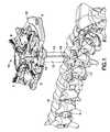
- FIG. 2is a partially exploded top perspective view of the retractor of FIG. 1 .
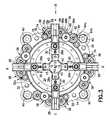
- FIG. 3is a top plan view of the retractor of FIG. 1 with the covers and the mounting bracket removed for clarity.
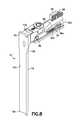
- FIG. 4is a top perspective view of one translatable arm of the retractor of FIG. 1 with a retractor member including a blade attached thereto with a switch being oriented in a first position.
- FIG. 5is a partial top perspective rear view of the retractor member shown in FIG. 4 .
- FIG. 6is a longitudinal cross-sectional view of the arm and retractor member of FIG. 4 .
- FIG. 7is a side elevation view of the arm shown in FIG. 4 with the blade in a toed position.
- FIG. 8is a top perspective view of the translatable arm and retractor member of FIG. 4 with the switch being oriented in a second position.
- FIG. 9is a partial side view of the retractor of FIG. 3 as viewed along the direction line IX in FIG. 3 with a portion of the retractor frame removed to reveal only the gearing mechanism in one quadrant of the retractor with the switch in the first position of FIG. 4 .
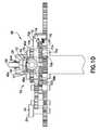
- FIG. 10is a further partial side view of the retractor gearing mechanism shown in FIG. 9 with the switch in the second position of FIG. 8
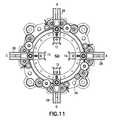
- FIG. 11is a further top plan view of the retractor shown in FIG. 3 with all the translatable arms and blades supported thereon having been translated radially outwardly to expand the surgical corridor.
- FIG. 12is a further top plan view of the retractor shown in FIG. 3 with one of the translatable arms and blade supported thereon having been translated radially outwardly to expand the surgical corridor in a selected direction.
- FIG. 13is a top perspective view of an alternative translatable arm with a retractor member supported thereon and a switch oriented in a first position.
- FIG. 14is a cross-sectional view of the alternative arm arrangement of FIG. 13 .
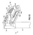
- FIG. 15is a top perspective view of the alternative arm arrangement of FIG. 13 , with the switch oriented in a second position.
- FIG. 16is a partial side view of the retractor of FIG. 3 as viewed along the direction line IX in FIG. 3 with a portion of the retractor frame removed to reveal only the gearing mechanism in one quadrant used with the alternative arm arrangement of FIG. 13 with the switch in the first position of FIG. 13 .
- FIG. 17is a further partial side view of the retractor gearing mechanism shown in FIG. 16 with the switch in the second position of FIG. 15 .
- retractor 10is shown in a particular arrangement for use in spinal surgery.
- retractor 10comprises four blades 12 each being identical and spaced radially substantially equally at approximately 90° relative to each other.
- the blades 12project substantially transversely downwardly from a frame 14 toward a human spine 16 to define an expandable minimally invasive corridor through which a surgical procedure including the implantation of an implant into an intradiscal space 18 of the spine 16 may be performed.
- the blades 12are supported by the retractor 10 whereby one or all or any combination of blades 12 may be translated in a radial direction from a single source actuator to expand an incision through bodily tissue in a controlled manner.
- the use of the retractor 10is from a direct lateral approach to the surgical site.
- the retractor 10is oriented to define four quadrants A, B, C and D, with quadrant A being in the caudal direction, quadrant B being in the anterior direction, quadrant C being in the cephalad direction and quadrant D being in the posterior direction.
- the desired orientationmay be maintained as will be further described by a bracket 20 suitably attached to the frame 14 of retractor 10 with the bracket 20 suitably connected to a rigid mounting arm connected to an operating table on which the patient is lying.
- Frame 14comprises a lower ring member 22 defining a generally central fully enclosed interior space 24 .
- Frame 14includes a cover 26 of substantially the same structure associated with each of the quadrants A, B, C and D each of which covers a gear mechanism for use in selectively translating the blades 12 , as will be described.
- the ring member 22supports four arms 28 one each at the quadrants A, B, C and D, each arm 28 supporting a blade 12 at a distal portion 28 a thereof.
- the arms 28are each radially individually translatable on the ring member 22 with the distal portions 28 a and blades attached thereto being movable within the interior space 24 along the radial directions indicated by arrows 30 in FIG. 3 .
- ring member 22supports a transmission member defined by a main gear 32 for rotational movement relative to ring member 22 and thereby relative to each arm 28 .
- Main gear 32comprises a plurality of gear teeth 32 a extending around the circumference of main gear 32 .
- Ring member 22supports an actuator 34 disposed in this particular arrangement between quadrants A and D.
- the lower portion of actuator 34defines a drive gear 34 a having gear teeth 34 b (see FIG. 9 ) in engagement with teeth 32 a on the main gear 32 .
- the upper portion of actuator 34defines a hex portion 34 c configured for engagement with a suitable tool such as, for example, a tool with a T-handle (not shown) having a complementary hex portion.
- a clutch mechanism 36that is configured to selectively engage a selected arm 28 with the main gear 32 , as will be detailed hereinbelow.
- a locking mechanism 38that cooperates with each arm 28 to allow translational movement of such arm 28 in only one direction and locking in the opposite direction, as will be described in further detail.
- ring member 22is configured to have a mounting portion 40 by which the retractor 10 may be directly connected to the operating table by a mounting arm or to which bracket 20 may be connected for attachment to the mounting arm.
- a retractor member 41 for releasable attachment to each housing 28comprises blade 12 and a blade support 43 .
- Blade support 43is disposed at the proximal end 41 a of retractor member 41 .
- Each blade 12is elongate and includes a proximal end 12 a attached to blade support 43 and a distal end 12 b .
- An outer surface 12 c extending along the length of the blade 12is configured to have a concave surface to form a quadrant of a surgical corridor formed by the four blades 12 having a substantially enclosed opening 42 as shown in FIG. 1 . As illustrated in FIG.
- blade support 43includes a dovetail slot 43 a that cooperates with a complementary dovetail slot 28 b in distal portion 28 a of arm 28 for releasably mounting retractor member 41 thereto.
- the blade support 43includes a flange 43 b which serves as a stop to properly seat retractor member 41 as the dovetail slots engage during insertion of retractor member 41 from above distal portion 28 a .
- Blade support 43may include an opening 43 c extending obliquely through an upper surface 43 d and opening through concave surface 12 c . Opening 43 c may be used for insertion of a light cable or other optical device to illuminate the opening 42 of the surgical corridor.
- the retractor member 41 with blade 12is releasably secured by a set screw 44 threadedly received in a threaded opening 28 c .
- the bottom of said screw 44is received in a recess 43 e formed in a side face 43 f of the blade support 43 .
- each arm 28comprises a housing 46 to which the distal portion 28 a is pivotally attached by a pivot pin 48 .
- the distal portion 28 aincludes a threaded opening 28 d for threadedly receiving therein a toeing screw 50 the upper portion 50 a of which is threaded to engage the threads of threaded opening 28 d .
- the lower portionis formed to have a generally spherical portion 50 b that is movably situated in a housing cavity 46 a .
- each arm 28movably supports therein an elongate bar such as an elongate shaft 52 .
- Shaft 52 in this particular arrangementis generally circular and is supported for rotation about its longitudinal axis 52 a within housing 46 .
- a series of linearly arranged gear teeth 54is provided lengthwise along the periphery of shaft 52 at least over a radial portion 52 b of the shaft 52 as depicted in FIG. 4 .
- Another series of gear teeth 55(See FIGS. 9 and 10 ) is arranged arcuately around a portion of the periphery of shaft 52 , the function of which will be described hereinbelow.
- FIG. 8The radial portion 52 c of the shaft 52 without gear teeth 54 along its length is illustrated in FIG. 8 .
- the teeth 54extend over a radial portion 52 b of about 90°, it being understood that the radial extent having teeth 54 may vary, provided there is both a longitudinal extent with teeth 54 and a longitudinal extent without teeth.
- a switch 56is rotatably supported by housing 46 .
- Switch 56comprises a rotatable knob 58 that is attached to a switch gear 60 for joint rotation therewith.
- Switch gear 60includes a plurality of gear teeth 60 a that are in engagement with teeth 55 on shaft 52 .
- teeth 54are arranged to be exposed through a window 46 c of housing 46 with knob 58 in a first orientation and gear teeth 60 a are in engagement with gear teeth 55 on shaft 52 .
- Rotation of the knob 58 approximately 180° to the orientation shown in FIGS. 8 and 10rotates the switch gear 60 which in turn through engagement of teeth 60 a with teeth 55 rotates shaft 52 about axis 52 a approximately 90° to a second position until the portion 52 c of the shaft 52 without gears is exposed through window 46 c .
- the arm 28may be selectively engaged with the main gear 32 as part of the clutch mechanism 36 .
- the teeth 54 on the shaft 52effectively function as a rack to convert the rotary motion of the main gear 32 into linear motion for translating the arm 28 relative to the ring member 22 through the clutch mechanism 36 .
- clutch mechanism 36includes a coupling gear mechanism 62 comprising three step gears 64 , 66 and 68 all of which are in engagement with each other.
- the step gears 64 , 66 and 68are used in the coupling gear mechanism 62 so as to provide a desired gear reduction between the rate at which main gear 32 rotates and the rate at which each arm 28 translates relative to ring member 22 .
- coupling gear mechanism 62may allow an arm 28 to translate at 1 mm increments for each one quarter turn of actuator 34 .
- Step gear 64comprises an upper smaller gear 64 a and a lower larger gear 64 b .
- Step gear 66comprises an upper larger gear 66 a and a lower smaller gear 66 b .
- Larger gear 66 ahas gear teeth in engagement with gear teeth on smaller gear 64 a of step gear 64 .
- Step gear 68comprises an upper smaller gear 68 a and a lower larger gear 68 b .
- Larger gear 68 bhas gear teeth in engagement with gear teeth on smaller gear 66 b of step gear 66 .
- Rotation of the actuator 34will effectively rotate the main gear 32 by the drive gear 34 a with each of the step gears 64 , 66 and 68 being rotated as a result of engagement of step gear 64 with the main gear 32 .
- Smaller gear 68 a of step gear 68is positioned on ring member 22 adjacent arm 28 so that the gear teeth thereon will be engageable with the teeth 54 on shaft 52 which are exposed through window 46 c of housing 46 .
- shaft 52is in the first position described with respect to FIG. 4 wherein gear teeth 54 on shaft 52 engage the teeth of smaller gear 68 a .
- Teeth 55are disposed on shaft 52 such that they do not make engagement with either the coupling gear mechanism 62 or the locking gear mechanism.
- switch 56has been actuated to place shaft 52 in such first position rotation of smaller gear 68 a will linearly move shaft 52 through engagement with teeth 54 thereby translating arm 28 radially with respect to ring member 22 .
- Smaller gear 68 awill effectively serve as the pinion to convert rotary motion of the coupling gear mechanism 62 into linear motion by engagement with teeth 54 on shaft 52 which, as described hereinabove, serves as a rack.
- coupling gear mechanism 62comprises three step gears 64 , 66 and 68 in the particular arrangement being described, other gear mechanisms or a single coupling member may be used in the retractor 10 .
- a single coupling membermay be defined by a single coupling gear with gear teeth with such single gear being disposed on ring member 22 and such that the gear teeth thereon are in engagement with gear teeth 32 a on main gear 32 and are engageable with teeth 54 on shaft 52 .
- shaft 52has been rotated by switch 56 to the second position as illustrated in FIG. 8 .
- switch gear 60has likewise been rotated causing gear teeth 60 a thereon through engagement with teeth 55 to have rotated shaft 52 about its axis 52 a to the second position.
- the radial portion 52 c of the shaft 52 without teeth 54is exposed through window 46 c .
- any rotation of smaller gear 68 a through rotation of main gear 32will not cause any translation of arm 28 .
- Locking mechanism 38comprises a locking gear 70 and an override gear 72 .
- Locking gear 70is a step gear that comprises an upper smaller gear 70 a and a lower larger gear 70 b .
- Smaller gear 70 ahas teeth engageable with teeth 54 on shaft 52 when shaft 52 is in the second position, as illustrated in FIG. 10 .
- Override gear 72comprises a gear 72 a having gear teeth in engagement with the gear teeth on larger gear 70 b .
- a pawl 74is supported on ring member 22 adjacent locking gear 70 , the pawl 74 being spring-loaded by a spring element such as a torsion spring 76 .
- Teeth 70 c on larger gear 70 bare formed as ratchet teeth such that when teeth 70 c are in engagement with pawl 74 locking gear 70 can only rotate in one direction is indicated by arrow 78 in FIG. 3 .
- arm 28is prevented from translating radially inwardly relative to ring member 22 . Release of the pawl 76 from the gear teeth 70 c on larger gear 70 b will allow free rotation of locking gear 70 whereby arm 28 may be freely and manually translatable.
- Override gear 72comprises an upper portion 72 b having an engagement surface such as a hex configuration for engagement with a complementary surface on a suitable instrument (not shown) for rotating override gear 72 .
- Rotation of override gear 72causes gear 72 a to rotate locking gear 70 through engagement with larger gear 70 b .
- gear teeth on smaller gear 70 abeing in engagement with teeth 54 on shaft 52
- shaft 52translates radially outwardly upon rotation of smaller gear 70 a .
- Pawl 76will prevent translation of shaft 52 radially inwardly.
- teeth 54 on shaft 52are shown in FIGS. 10 and 11 as extending over a radial extent to engage gear mechanism 62 in the first position and the locking mechanism 38 in the second position, teeth 54 may be configured on shaft 52 to extend over a radial extent to engage both the coupling gear mechanism 62 and the locking mechanism 38 when the shaft 52 is being rotated from the first position to the second position. Such a construction would substantially prevent arm 28 from radially slipping during the transition between the first to the second position.
- the retractor frame 14may have a maximum outer diameter of about 5.26 inches.
- the retractor 10will be relatively easy to handle by a surgeon, will present a relatively small footprint and generally fit between a patient's iliac crest and ribs during surgery.
- all the components of the retractor 10may be formed of aluminum except for the gears which would be formed of stainless steel.
- the aluminum componentsare desirable for not only their strength and rigidity but also for use with fluoroscopic imaging whereby the aluminum material is not fully opaque but allows a degree of translucency to aid fluoroscopic visibility for the surgeon.
- a surgeonforms an initial incision through the tissue of the patient from the lateral aspect in a manner to create a surgical corridor through the psoas muscle down to a surgical site adjacent the lateral surface of a spinal disc.
- the initial incisionmay be dilated by a series of sequentially larger dilation cannulas as is conventionally known in the art to further expand the incision. Detection of nerves during the dilation process may be performed as is known in the art by conventional neural monitoring techniques.
- Suitable dilation and neural monitoring techniquesare described, for example, in commonly assigned PCT Application Number PCT/US12/54051, entitled “Apparatus for Dilating Bodily Tissue and for Monitoring Neural Activity in the Dilated Bodily Tissue”, filed Sep. 7, 2012, and published as WO 2013/036705A1 on Mar. 14, 2013, this PCT Application being incorporated herein by reference in its entirety.
- a kitmay be provided with a set of different length blades 12 , together with various other instruments and tools for use during surgery.
- the length of blades 12may range from 9 cm-17 cm.
- a substantially enclosed openingmeans an opening wherein the longitudinal edges of each of the blades 12 are in contact or a substantially small space exists between each of the blades 12 along their lengths.
- the opening 42is formed so that the blades 12 simultaneously slide over the largest of the sequential dilation cannulas in a relatively close sliding fit.
- the blades 12may be formed to have an arcuate extent less than the arcuate extent of the blades supports 43 , as seen in FIG. 4 .
- the side edges of the blade supports 43may be in contact as the retractor 10 is positioned over the largest dilation cannula with a small gap between the longitudinal edges of the blades along the lengths.
- the initial opening 42may range from 13 mm-18 mm, although different opening configurations and positions may be achieved.
- Bracket 20as shown in FIGS. 1-2 is generally horse-shoe shaped with a pair of arms 20 a and 20 b each terminating with a thumbscrew 80 and 82 .
- Thumbscrew 80terminates in a threaded portion 80 a for threaded engagement in a threaded hole 40 a in one mounting portion 40 and thumbscrew 82 terminates in a threaded portion 82 a for threaded engagement in threaded hole 40 a in a second mounting portion 40 .
- each mounting bracket arm 20 a and 20 bmay be configured to have a polygonal shape to match a complementary polygonal shape in each mounting portion 40 so as to provide a secure, rigid connection between the retractor frame 14 and the bracket 20 .
- Bracket 20includes a mounting portion 20 c at the base of the bracket 20 formed similarly to mounting portions 40 for secure connection thereto to a rigid mounting arm which in turn is connected to the operating table. While it should be appreciated that an individual mounting portion 40 on the retractor frame 14 may be used to attach the retractor 10 to the operating table via a rigid mounting arm, use of the bracket 20 which attaches to at least two mounting portions 40 on the retractor 10 provides a more stable, rigid connection.
- the dilation cannulasmay be removed from the incision.
- the surgeonmay now select which quadrants of the opening 42 may be expanded. For example, if the surgeon wishes to expand the incision in all of the quadrants A, B, C and D, switch 56 on all of the housings 46 would be rotated to the first position as depicted in FIG. 4 . With a suitable tool the surgeon will rotate actuator 34 which will rotate main gear 32 and through the clutch mechanism 36 all arms 28 will translate radially outwardly upon rotation of the actuator 34 , expanding the initial opening 42 equally in all directions to the expanded opening 42 a as shown in FIG. 11 .
- the initial opening 42may be increased to an expanded opening 42 a in the range of 14 mm-36 mm, although other suitable ranges are contemplated based upon the application. Smaller expansion may be desirable wherein an implant is inserted through the expanded opening to the surgical site, such as in the intradiscal space, while a larger expansion may be desired when additional surgical procedures, such as subsequent grafting around the implant are performed through the retractor. Any or all of the distal ends 12 b may be further expanded radially outwardly in a toeing manner as described hereinabove with respect to FIG. 7 . Suitable illuminating elements may be used in conjunction with one or more retractor members 41 as described hereinabove either before or after blades 12 are radially expanded or toed.
- the surgeonmay wish to radially expand the dilated incision in only one direction, such as in quadrant A.
- the surgeonwould position switch 56 on arm 28 in quadrant A in the first position while moving switch 56 on the remaining arms 28 in quadrants B, C and D to the second position.
- Rotation of the actuator by the suitable toolrotates main gear 32 and with only arm 28 in quadrant A being selectively engaged with main gear 32 through its associated clutch mechanism 36 , only this arm 28 will translate radially outwardly as shown in FIG. 12 .
- a surgeonmay selectively translate any one or all of the arms 28 or any combination of arms 28 in the use of retractor 10 in one or more selected desired directions from a single source, such as actuator 34 .
- retractor 10As an alternative to movable bar being a rotatable shaft 52 , the movable bar may be provided to selectively move linearly between the first position and a second position described hereinabove. As illustrated in FIGS. 13-17 , a bar 152 supported in a modified arm 128 having a housing 146 is movable in a transverse direction from the first position to the second position, as will be described. Bar 152 is elongate and generally rectangular defining a longitudinal axis 152 a .
- Gear teeth 154 bare linearly disposed on one lateral side of bar 152 that faces smaller gear 68 a of the coupling gear mechanism 62 .
- Similar gear teeth 152 care linearly disposed on the opposite lateral side of bar 152 that faces smaller gear 70 a of the locking mechanism 38 .
- Smaller gear 70 ais arranged on ring member 22 at a different higher plane than smaller gear 68 a , as seen in FIGS. 16 and 17 .
- a switch 156 having a knob 158is rotatably supported by housing 146 , switch 156 having a threaded post 156 a threadedly connected to a threaded opening 152 d in bar 152 .
- the bar 152 and switch 156are in the first position, and as seen in FIG. 16 gear teeth 154 b are in engagement with smaller gear 68 a . In this first position, gear teeth 152 c do not engage smaller gear 70 a .
- Rotation of switch 156 by knob 158 to the position illustrated in FIG. 15rotates threaded post 156 a causing bar 152 to elevate in a linear direction generally orthogonal to axis 152 a to the second position.
- gear teeth 152 care in engagement with smaller gear 70 a while gear teeth 152 b do not engage smaller gear 68 a .
- the retractor with the alternative arm arrangementfunctions in the same manner as set forth regarding the embodiments previously described hereinabove.
- retractor 10may be configured for use with as few as two blades or more than four. It should further be appreciated that while it is desirable in some instances for all of the blades to be independently translatable, there may be certain situations wherein a pair of blades 12 , such as those in quadrants A and B are jointly engageable with main gear 32 through clutch mechanism 36 by movement of a single switch 56 . In addition, there may be certain other applications wherein one or more blades of the retractor are fixed relative to frame 14 with at least one arm 28 and the blade supported thereon being selectively engageable with main gear 32 through clutch mechanism 36 .
Landscapes
- Health & Medical Sciences (AREA)
- Life Sciences & Earth Sciences (AREA)
- Surgery (AREA)
- Heart & Thoracic Surgery (AREA)
- Engineering & Computer Science (AREA)
- Biomedical Technology (AREA)
- Nuclear Medicine, Radiotherapy & Molecular Imaging (AREA)
- Medical Informatics (AREA)
- Molecular Biology (AREA)
- Animal Behavior & Ethology (AREA)
- General Health & Medical Sciences (AREA)
- Public Health (AREA)
- Veterinary Medicine (AREA)
- Surgical Instruments (AREA)
Abstract
Description
Claims (29)
Priority Applications (4)
| Application Number | Priority Date | Filing Date | Title |
|---|---|---|---|
| US13/891,697US8727975B1 (en) | 2013-05-10 | 2013-05-10 | Retractor for use in spinal surgery |
| PCT/US2014/036107WO2014182522A1 (en) | 2013-05-10 | 2014-04-30 | Retractor for use in spinal surgery |
| US14/277,260US9545250B2 (en) | 2013-05-10 | 2014-05-14 | Kit of parts for use in retracting body tissue |
| US14/277,511US9498200B2 (en) | 2013-05-10 | 2014-05-14 | Method of retracting body tissue during surgery |
Applications Claiming Priority (1)
| Application Number | Priority Date | Filing Date | Title |
|---|---|---|---|
| US13/891,697US8727975B1 (en) | 2013-05-10 | 2013-05-10 | Retractor for use in spinal surgery |
Related Child Applications (2)
| Application Number | Title | Priority Date | Filing Date |
|---|---|---|---|
| US14/277,260ContinuationUS9545250B2 (en) | 2013-05-10 | 2014-05-14 | Kit of parts for use in retracting body tissue |
| US14/277,511ContinuationUS9498200B2 (en) | 2013-05-10 | 2014-05-14 | Method of retracting body tissue during surgery |
Publications (1)
| Publication Number | Publication Date |
|---|---|
| US8727975B1true US8727975B1 (en) | 2014-05-20 |
Family
ID=50692187
Family Applications (3)
| Application Number | Title | Priority Date | Filing Date |
|---|---|---|---|
| US13/891,697ActiveUS8727975B1 (en) | 2013-05-10 | 2013-05-10 | Retractor for use in spinal surgery |
| US14/277,511Expired - Fee RelatedUS9498200B2 (en) | 2013-05-10 | 2014-05-14 | Method of retracting body tissue during surgery |
| US14/277,260Expired - Fee RelatedUS9545250B2 (en) | 2013-05-10 | 2014-05-14 | Kit of parts for use in retracting body tissue |
Family Applications After (2)
| Application Number | Title | Priority Date | Filing Date |
|---|---|---|---|
| US14/277,511Expired - Fee RelatedUS9498200B2 (en) | 2013-05-10 | 2014-05-14 | Method of retracting body tissue during surgery |
| US14/277,260Expired - Fee RelatedUS9545250B2 (en) | 2013-05-10 | 2014-05-14 | Kit of parts for use in retracting body tissue |
Country Status (2)
| Country | Link |
|---|---|
| US (3) | US8727975B1 (en) |
| WO (1) | WO2014182522A1 (en) |
Cited By (25)
| Publication number | Priority date | Publication date | Assignee | Title |
|---|---|---|---|---|
| US20150182211A1 (en)* | 2013-12-02 | 2015-07-02 | Thompson Surgical Instruments, Inc. | Surgical retractor with angling device |
| US20150313585A1 (en)* | 2014-05-01 | 2015-11-05 | Blackstone Medical, Inc. | Integrated retractor-distractor system for use with modular bone screws |
| US20160030030A1 (en)* | 2014-07-31 | 2016-02-04 | Tedan Surgical Innovations, LLC. | Surgical retractor with a locking retractor blade |
| US20160074029A1 (en)* | 2014-08-13 | 2016-03-17 | Nuvasive, Inc. | Minimally disruptive retractor and associated methods for spinal surgery |
| US9861495B2 (en) | 2013-03-14 | 2018-01-09 | Raed M. Ali, M.D., Inc. | Lateral interbody fusion devices, systems and methods |
| US9951904B2 (en) | 2015-03-24 | 2018-04-24 | Stryker Corporation | Rotatable seat clamps for rail clamp |
| US9980750B2 (en) | 2011-03-18 | 2018-05-29 | Raed M. Ali, M.D., Inc. | Spinal fusion devices and systems |
| US10034662B2 (en) | 2014-07-31 | 2018-07-31 | Tedan Surgical Innovations, LLC. | Surgical retractor with a locking retractor blade and swivel side arms |
| US10179054B2 (en) | 2008-02-06 | 2019-01-15 | Jeffrey B. Kleiner | Spinal fusion cage system with inserter |
| US10195053B2 (en) | 2009-09-18 | 2019-02-05 | Spinal Surgical Strategies, Llc | Bone graft delivery system and method for using same |
| US10201355B2 (en) | 2009-02-06 | 2019-02-12 | Kleiner Intellectual Property, Llc | Angled surgical tool for removing tissue from within an intervertebral space |
| US10245159B1 (en) | 2009-09-18 | 2019-04-02 | Spinal Surgical Strategies, Llc | Bone graft delivery system and method for using same |
| CN110381866A (en)* | 2017-03-08 | 2019-10-25 | 美多斯国际有限公司 | Surgery entrance is stablized |
| US10478364B2 (en) | 2014-03-10 | 2019-11-19 | Stryker Corporation | Limb positioning system |
| US10687962B2 (en) | 2013-03-14 | 2020-06-23 | Raed M. Ali, M.D., Inc. | Interbody fusion devices, systems and methods |
| WO2020219830A1 (en)* | 2019-04-24 | 2020-10-29 | Nuvasive, Inc. | Transmission assembly |
| WO2021062320A1 (en)* | 2019-09-25 | 2021-04-01 | Astura Medical Inc. | Tissue retractor |
| US10973656B2 (en) | 2009-09-18 | 2021-04-13 | Spinal Surgical Strategies, Inc. | Bone graft delivery system and method for using same |
| US10987228B2 (en) | 2011-03-18 | 2021-04-27 | Raed M. Ali, M.D., Inc. | Devices and methods for transpedicular stabilization of the spine |
| US11253243B2 (en) | 2019-06-18 | 2022-02-22 | Nuvasive, Inc. | Tissue retraction system |
| US11375989B2 (en) | 2019-12-10 | 2022-07-05 | Thompson Surgical Instruments, Inc. | Retractor system, swivel lock, and surgical retractor blade |
| US11547395B2 (en) | 2019-06-18 | 2023-01-10 | Nuvasive, Inc. | Tissue retraction system |
| US11666455B2 (en) | 2009-09-18 | 2023-06-06 | Spinal Surgical Strategies, Inc., A Nevada Corporation | Bone graft delivery devices, systems and kits |
| US11864739B2 (en) | 2019-11-05 | 2024-01-09 | Matthew L. Bycer | Surgical retractor |
| US12171419B2 (en) | 2021-10-06 | 2024-12-24 | K2M, Inc. | Offset Hohmann |
Families Citing this family (27)
| Publication number | Priority date | Publication date | Assignee | Title |
|---|---|---|---|---|
| WO2006058221A2 (en) | 2004-11-24 | 2006-06-01 | Abdou Samy M | Devices and methods for inter-vertebral orthopedic device placement |
| US8992558B2 (en) | 2008-12-18 | 2015-03-31 | Osteomed, Llc | Lateral access system for the lumbar spine |
| US8764806B2 (en)* | 2009-12-07 | 2014-07-01 | Samy Abdou | Devices and methods for minimally invasive spinal stabilization and instrumentation |
| US10357239B2 (en) | 2011-03-08 | 2019-07-23 | Pioneer Surgical Technology, Inc. | Apparatus and method for enlarging an incision |
| US9579095B2 (en) | 2011-03-08 | 2017-02-28 | Pioneer Surgical Technology, Inc. | Apparatus and method for enlarging an incision |
| US8845728B1 (en) | 2011-09-23 | 2014-09-30 | Samy Abdou | Spinal fixation devices and methods of use |
| US20130226240A1 (en) | 2012-02-22 | 2013-08-29 | Samy Abdou | Spinous process fixation devices and methods of use |
| US9198767B2 (en) | 2012-08-28 | 2015-12-01 | Samy Abdou | Devices and methods for spinal stabilization and instrumentation |
| US9320617B2 (en) | 2012-10-22 | 2016-04-26 | Cogent Spine, LLC | Devices and methods for spinal stabilization and instrumentation |
| US10857003B1 (en) | 2015-10-14 | 2020-12-08 | Samy Abdou | Devices and methods for vertebral stabilization |
| WO2018039228A1 (en) | 2016-08-23 | 2018-03-01 | Stryker European Holdings I, Llc | Instrumentation for the implantation of spinal implants |
| US10973648B1 (en) | 2016-10-25 | 2021-04-13 | Samy Abdou | Devices and methods for vertebral bone realignment |
| US10744000B1 (en) | 2016-10-25 | 2020-08-18 | Samy Abdou | Devices and methods for vertebral bone realignment |
| CN107411786A (en)* | 2017-05-18 | 2017-12-01 | 南阳市中心医院 | A kind of hepatobiliary surgery hooking device |
| CN107233112A (en)* | 2017-06-06 | 2017-10-10 | 河南省人民医院 | A kind of liver and gall surgical department operation pulling device |
| EP3545857B1 (en) | 2018-03-30 | 2024-01-03 | Stryker European Operations Holdings LLC | Lateral access retractor and core insertion |
| CN108378882B (en)* | 2018-04-09 | 2019-11-22 | 郑州大学第一附属医院 | A kind of tracheotomy dilation device |
| CN108553135B (en)* | 2018-04-11 | 2020-05-05 | 郑州大学第一附属医院 | Special planetary rotary type expansion device for interventional operation |
| US11179248B2 (en) | 2018-10-02 | 2021-11-23 | Samy Abdou | Devices and methods for spinal implantation |
| US11413029B2 (en) | 2018-10-24 | 2022-08-16 | Stryker European Operations Holdings Llc | Anterior to psoas instrumentation |
| CN109998612B (en)* | 2019-04-15 | 2020-07-14 | 遵义市红花岗区人民医院 | Retractor for brain surgery |
| CN110353743B (en)* | 2019-07-23 | 2020-10-09 | 宫锡和 | Scalp retractor for neurosurgery |
| US11564674B2 (en) | 2019-11-27 | 2023-01-31 | K2M, Inc. | Lateral access system and method of use |
| US11204060B2 (en) | 2019-11-27 | 2021-12-21 | Medos International Sari | Selectively lockable ball and socket joint |
| US11229464B2 (en) | 2019-12-04 | 2022-01-25 | Medos International Sarl | Apparatus for driver-specific backout prevention |
| US11627952B2 (en) | 2020-06-29 | 2023-04-18 | Surgalign Spine Technologies, Inc. | Surgical retractor |
| US12369897B2 (en)* | 2021-05-07 | 2025-07-29 | Alphatec Spine, Inc. | Surgical retractors and methods of using the same |
Citations (31)
| Publication number | Priority date | Publication date | Assignee | Title |
|---|---|---|---|---|
| US475975A (en) | 1892-05-31 | Speculum | ||
| US497064A (en) | 1893-05-09 | Speculum | ||
| FR542744A (en) | 1921-10-26 | 1922-08-21 | Diaphragm speculum, with multiple branches and double opening movement | |
| US2083573A (en) | 1936-04-18 | 1937-06-15 | Clifford V Morgan | Speculum |
| US3522799A (en) | 1967-06-21 | 1970-08-04 | William K Gauthier | Surgical retractor device |
| US3749088A (en) | 1971-06-23 | 1973-07-31 | W Kohlmann | Surgical retractor device |
| US3965890A (en) | 1974-10-18 | 1976-06-29 | William Kohlmann Gauthier | Surgical retractor |
| US4130113A (en) | 1976-12-15 | 1978-12-19 | Richards Manufacturing Co., Inc. | Retractor |
| US5520610A (en) | 1991-05-31 | 1996-05-28 | Giglio; Steven R. | Self retaining retractor |
| US5947896A (en) | 1996-04-26 | 1999-09-07 | United States Surgical Corporation | Heart stabilizer apparatus and method for use |
| US5957902A (en) | 1998-09-28 | 1999-09-28 | Teves; Leonides Y. | Surgical tool for enlarging puncture opening made by trocar |
| US6074343A (en) | 1999-04-16 | 2000-06-13 | Nathanson; Michael | Surgical tissue retractor |
| US6102853A (en) | 1998-01-23 | 2000-08-15 | United States Surgical Corporation | Surgical instrument |
| WO2001003586A1 (en) | 1999-07-07 | 2001-01-18 | David Michaeli | Concentrically expansible needle retractor |
| US6402780B2 (en) | 1996-02-23 | 2002-06-11 | Cardiovascular Technologies, L.L.C. | Means and method of replacing a heart valve in a minimally invasive manner |
| US6616605B2 (en) | 2001-02-15 | 2003-09-09 | Genesee Biomedical, Inc. | Quadretractor and method of use |
| US6712795B1 (en) | 2002-06-07 | 2004-03-30 | Lester Cohen | Surgical procedure and apparatus |
| US20040087833A1 (en) | 2002-10-30 | 2004-05-06 | Thomas Bauer | Retractor |
| US20060135852A1 (en) | 2004-12-20 | 2006-06-22 | Tibor Koros | Rotatable holder assembly for a surgical retractor blade |
| US20070208228A1 (en) | 2006-03-01 | 2007-09-06 | Nicholas Pavento | Surgical retractors and methods of minimally invasive surgery |
| US20070238932A1 (en) | 2006-03-08 | 2007-10-11 | Jones Robert J | Surgical retractor and retractor assembly |
| US7344495B2 (en)* | 2004-01-27 | 2008-03-18 | Arvik Enterprises, Llc | Surgical retractor apparatus for use with a surgical port |
| US20080319268A1 (en) | 2005-12-15 | 2008-12-25 | David Michaeli | Radial Expansible Retractor For Minimally Invasive Surgery |
| US7722570B2 (en) | 2000-05-24 | 2010-05-25 | Applied Medical Resources Corporation | Surgical seal |
| US7758501B2 (en)* | 2006-01-04 | 2010-07-20 | Depuy Spine, Inc. | Surgical reactors and methods of minimally invasive surgery |
| US7985179B2 (en) | 2006-01-23 | 2011-07-26 | Pioneer Surgical Technology | Retraction apparatus and method of use |
| US8062217B2 (en) | 2007-01-26 | 2011-11-22 | Theken Spine, Llc | Surgical retractor with removable blades and method of use |
| US8251902B2 (en) | 2005-10-17 | 2012-08-28 | Lanx, Inc. | Pedicle guided retractor system |
| US20120232349A1 (en) | 2011-03-08 | 2012-09-13 | Pioneer Surgical Technology, Inc. | Apparatus And Method For Enlarging An Incision |
| US8355780B2 (en) | 2003-09-25 | 2013-01-15 | Nuvasive, Inc. | Surgical access system and related methods |
| US8409089B2 (en) | 2010-02-24 | 2013-04-02 | Meni-Med Ltd. | Surgical retractor |
Family Cites Families (16)
| Publication number | Priority date | Publication date | Assignee | Title |
|---|---|---|---|---|
| US5967973A (en)* | 1996-04-26 | 1999-10-19 | United States Surgical | Surgical retractor and method of surgery |
| US20040059194A1 (en)* | 2002-07-18 | 2004-03-25 | Minnesota Scientific, Inc. | Method and apparatus for replacing knee-joint |
| US7905840B2 (en)* | 2003-10-17 | 2011-03-15 | Nuvasive, Inc. | Surgical access system and related methods |
| US8038611B2 (en)* | 2003-12-18 | 2011-10-18 | Depuy Spine, Inc. | Surgical methods and surgical kits |
| US7195592B2 (en)* | 2004-01-27 | 2007-03-27 | Sundaram Ravikumar | Surgical retractor apparatus for use with a surgical port |
| US8080061B2 (en)* | 2005-06-20 | 2011-12-20 | Synthes Usa, Llc | Apparatus and methods for treating bone |
| US8105236B2 (en)* | 2005-07-11 | 2012-01-31 | Kyphon Sarl | Surgical access device, system, and methods of use |
| EP1988814B1 (en)* | 2006-03-01 | 2014-07-02 | Boss Instruments, Ltd. | Surgical retractor frame system |
| JP2010504157A (en)* | 2006-09-22 | 2010-02-12 | アルファテック スパイン, インコーポレイテッド | Retractor |
| US7922658B2 (en)* | 2006-11-09 | 2011-04-12 | Ebi, Llc | Surgical retractor device and related methods |
| US20080183044A1 (en)* | 2007-01-26 | 2008-07-31 | Dennis Colleran | Flexible surgical retractor and method of use |
| US8974380B2 (en)* | 2010-02-24 | 2015-03-10 | Meni-Med Ltd | Surgical retractor |
| US20110257487A1 (en)* | 2010-04-15 | 2011-10-20 | John Thalgott | Lateral and Anterior Lateral Retractor System |
| WO2013036705A1 (en) | 2011-09-09 | 2013-03-14 | Spine Wave, Inc. | Apparatus for dilating bodily tissue and for monitoring neural activity in the dilated bodily tissue |
| US8821394B2 (en) | 2012-03-30 | 2014-09-02 | DePuy Synthes Products, LLC | Methods and devices for tissue retraction |
| US9693761B2 (en) | 2012-10-24 | 2017-07-04 | Blackstone Medical, Inc. | Retractor device and method |
- 2013
- 2013-05-10USUS13/891,697patent/US8727975B1/enactiveActive
- 2014
- 2014-04-30WOPCT/US2014/036107patent/WO2014182522A1/enactiveApplication Filing
- 2014-05-14USUS14/277,511patent/US9498200B2/ennot_activeExpired - Fee Related
- 2014-05-14USUS14/277,260patent/US9545250B2/ennot_activeExpired - Fee Related
Patent Citations (32)
| Publication number | Priority date | Publication date | Assignee | Title |
|---|---|---|---|---|
| US475975A (en) | 1892-05-31 | Speculum | ||
| US497064A (en) | 1893-05-09 | Speculum | ||
| FR542744A (en) | 1921-10-26 | 1922-08-21 | Diaphragm speculum, with multiple branches and double opening movement | |
| US2083573A (en) | 1936-04-18 | 1937-06-15 | Clifford V Morgan | Speculum |
| US3522799A (en) | 1967-06-21 | 1970-08-04 | William K Gauthier | Surgical retractor device |
| US3749088A (en) | 1971-06-23 | 1973-07-31 | W Kohlmann | Surgical retractor device |
| US3965890A (en) | 1974-10-18 | 1976-06-29 | William Kohlmann Gauthier | Surgical retractor |
| US4130113A (en) | 1976-12-15 | 1978-12-19 | Richards Manufacturing Co., Inc. | Retractor |
| US5520610A (en) | 1991-05-31 | 1996-05-28 | Giglio; Steven R. | Self retaining retractor |
| US6402780B2 (en) | 1996-02-23 | 2002-06-11 | Cardiovascular Technologies, L.L.C. | Means and method of replacing a heart valve in a minimally invasive manner |
| US5947896A (en) | 1996-04-26 | 1999-09-07 | United States Surgical Corporation | Heart stabilizer apparatus and method for use |
| US6102853A (en) | 1998-01-23 | 2000-08-15 | United States Surgical Corporation | Surgical instrument |
| US5957902A (en) | 1998-09-28 | 1999-09-28 | Teves; Leonides Y. | Surgical tool for enlarging puncture opening made by trocar |
| US6074343A (en) | 1999-04-16 | 2000-06-13 | Nathanson; Michael | Surgical tissue retractor |
| WO2001003586A1 (en) | 1999-07-07 | 2001-01-18 | David Michaeli | Concentrically expansible needle retractor |
| US7722570B2 (en) | 2000-05-24 | 2010-05-25 | Applied Medical Resources Corporation | Surgical seal |
| US6616605B2 (en) | 2001-02-15 | 2003-09-09 | Genesee Biomedical, Inc. | Quadretractor and method of use |
| US6712795B1 (en) | 2002-06-07 | 2004-03-30 | Lester Cohen | Surgical procedure and apparatus |
| US20040087833A1 (en) | 2002-10-30 | 2004-05-06 | Thomas Bauer | Retractor |
| US8355780B2 (en) | 2003-09-25 | 2013-01-15 | Nuvasive, Inc. | Surgical access system and related methods |
| US7344495B2 (en)* | 2004-01-27 | 2008-03-18 | Arvik Enterprises, Llc | Surgical retractor apparatus for use with a surgical port |
| US20060135852A1 (en) | 2004-12-20 | 2006-06-22 | Tibor Koros | Rotatable holder assembly for a surgical retractor blade |
| US8251902B2 (en) | 2005-10-17 | 2012-08-28 | Lanx, Inc. | Pedicle guided retractor system |
| US20080319268A1 (en) | 2005-12-15 | 2008-12-25 | David Michaeli | Radial Expansible Retractor For Minimally Invasive Surgery |
| US7758501B2 (en)* | 2006-01-04 | 2010-07-20 | Depuy Spine, Inc. | Surgical reactors and methods of minimally invasive surgery |
| US20110004067A1 (en) | 2006-01-04 | 2011-01-06 | Connie Marchek | Surgical Retractors and Methods of Minimally Invasive Surgery |
| US7985179B2 (en) | 2006-01-23 | 2011-07-26 | Pioneer Surgical Technology | Retraction apparatus and method of use |
| US20070208228A1 (en) | 2006-03-01 | 2007-09-06 | Nicholas Pavento | Surgical retractors and methods of minimally invasive surgery |
| US20070238932A1 (en) | 2006-03-08 | 2007-10-11 | Jones Robert J | Surgical retractor and retractor assembly |
| US8062217B2 (en) | 2007-01-26 | 2011-11-22 | Theken Spine, Llc | Surgical retractor with removable blades and method of use |
| US8409089B2 (en) | 2010-02-24 | 2013-04-02 | Meni-Med Ltd. | Surgical retractor |
| US20120232349A1 (en) | 2011-03-08 | 2012-09-13 | Pioneer Surgical Technology, Inc. | Apparatus And Method For Enlarging An Incision |
Non-Patent Citations (1)
| Title |
|---|
| Fisso, Articulated arm for surgical applications with quick central fixation, dated Oct. 2007 (6 pages). |
Cited By (45)
| Publication number | Priority date | Publication date | Assignee | Title |
|---|---|---|---|---|
| US10179054B2 (en) | 2008-02-06 | 2019-01-15 | Jeffrey B. Kleiner | Spinal fusion cage system with inserter |
| US10201355B2 (en) | 2009-02-06 | 2019-02-12 | Kleiner Intellectual Property, Llc | Angled surgical tool for removing tissue from within an intervertebral space |
| US10973656B2 (en) | 2009-09-18 | 2021-04-13 | Spinal Surgical Strategies, Inc. | Bone graft delivery system and method for using same |
| US11660208B2 (en) | 2009-09-18 | 2023-05-30 | Spinal Surgical Strategies, Inc. | Bone graft delivery system and method for using same |
| US12167971B2 (en) | 2009-09-18 | 2024-12-17 | Spinal Surgical Strategies, Inc. | Bone graft delivery devices, systems and kits |
| US11666455B2 (en) | 2009-09-18 | 2023-06-06 | Spinal Surgical Strategies, Inc., A Nevada Corporation | Bone graft delivery devices, systems and kits |
| US10245159B1 (en) | 2009-09-18 | 2019-04-02 | Spinal Surgical Strategies, Llc | Bone graft delivery system and method for using same |
| US12053393B2 (en) | 2009-09-18 | 2024-08-06 | Spinal Surgical Strategies, Inc. | Bone graft delivery system and method for use |
| US10195053B2 (en) | 2009-09-18 | 2019-02-05 | Spinal Surgical Strategies, Llc | Bone graft delivery system and method for using same |
| US9980750B2 (en) | 2011-03-18 | 2018-05-29 | Raed M. Ali, M.D., Inc. | Spinal fusion devices and systems |
| US10987228B2 (en) | 2011-03-18 | 2021-04-27 | Raed M. Ali, M.D., Inc. | Devices and methods for transpedicular stabilization of the spine |
| US10548742B2 (en) | 2013-03-14 | 2020-02-04 | Raed M. Ali, M.D., Inc. | Lateral interbody fusion devices, systems and methods |
| US11304824B2 (en) | 2013-03-14 | 2022-04-19 | Raed M. Ali, M.D., Inc. | Interbody fusion devices, systems and methods |
| US10045857B2 (en) | 2013-03-14 | 2018-08-14 | Raed M. Ali, M.D., Inc. | Lateral interbody fusion devices, systems and methods |
| US10687962B2 (en) | 2013-03-14 | 2020-06-23 | Raed M. Ali, M.D., Inc. | Interbody fusion devices, systems and methods |
| US9861495B2 (en) | 2013-03-14 | 2018-01-09 | Raed M. Ali, M.D., Inc. | Lateral interbody fusion devices, systems and methods |
| US11413162B2 (en) | 2013-03-14 | 2022-08-16 | Raed M. Ali, M.D., Inc. | Spinal fusion devices, systems and methods |
| US9872675B2 (en)* | 2013-12-02 | 2018-01-23 | Thompson Surgical Instruments, Inc. | Surgical retractor with angling device |
| US20150182211A1 (en)* | 2013-12-02 | 2015-07-02 | Thompson Surgical Instruments, Inc. | Surgical retractor with angling device |
| US10478364B2 (en) | 2014-03-10 | 2019-11-19 | Stryker Corporation | Limb positioning system |
| US20150313585A1 (en)* | 2014-05-01 | 2015-11-05 | Blackstone Medical, Inc. | Integrated retractor-distractor system for use with modular bone screws |
| US9414828B2 (en)* | 2014-05-01 | 2016-08-16 | Blackstone Medical, Inc. | Integrated retractor-distractor system for use with modular bone screws |
| US10034662B2 (en) | 2014-07-31 | 2018-07-31 | Tedan Surgical Innovations, LLC. | Surgical retractor with a locking retractor blade and swivel side arms |
| US20160030030A1 (en)* | 2014-07-31 | 2016-02-04 | Tedan Surgical Innovations, LLC. | Surgical retractor with a locking retractor blade |
| US9636097B2 (en)* | 2014-07-31 | 2017-05-02 | Tedan Surgical Innovations, LLC. | Surgical retractor with a locking retractor blade |
| US9962147B2 (en)* | 2014-08-13 | 2018-05-08 | Nuvasive, Inc. | Minimally disruptive retractor and associated methods for spinal surgery |
| US12108947B2 (en) | 2014-08-13 | 2024-10-08 | Nuvasive, Inc. | Minimally disruptive retractor and associated methods for spinal surgery |
| US20160074029A1 (en)* | 2014-08-13 | 2016-03-17 | Nuvasive, Inc. | Minimally disruptive retractor and associated methods for spinal surgery |
| US11399816B2 (en) | 2014-08-13 | 2022-08-02 | Nuvasive, Inc. | Minimally disruptive retractor and associated methods for spinal surgery |
| US9795370B2 (en)* | 2014-08-13 | 2017-10-24 | Nuvasive, Inc. | Minimally disruptive retractor and associated methods for spinal surgery |
| US9951904B2 (en) | 2015-03-24 | 2018-04-24 | Stryker Corporation | Rotatable seat clamps for rail clamp |
| CN110381866A (en)* | 2017-03-08 | 2019-10-25 | 美多斯国际有限公司 | Surgery entrance is stablized |
| CN110381866B (en)* | 2017-03-08 | 2022-09-09 | 美多斯国际有限公司 | Surgical portal stabilization |
| WO2020219830A1 (en)* | 2019-04-24 | 2020-10-29 | Nuvasive, Inc. | Transmission assembly |
| US11602337B2 (en) | 2019-04-24 | 2023-03-14 | Nuvasive, Inc. | Transmission assembly |
| US12274429B2 (en) | 2019-04-24 | 2025-04-15 | Nuvasive, Inc. | Transmission assembly |
| US11547395B2 (en) | 2019-06-18 | 2023-01-10 | Nuvasive, Inc. | Tissue retraction system |
| US11969161B2 (en) | 2019-06-18 | 2024-04-30 | Nuvasive, Inc. | Tissue retraction system |
| US11253243B2 (en) | 2019-06-18 | 2022-02-22 | Nuvasive, Inc. | Tissue retraction system |
| US11457906B2 (en)* | 2019-09-25 | 2022-10-04 | Astura Medical Inc | Tissue retractor |
| WO2021062320A1 (en)* | 2019-09-25 | 2021-04-01 | Astura Medical Inc. | Tissue retractor |
| US11864739B2 (en) | 2019-11-05 | 2024-01-09 | Matthew L. Bycer | Surgical retractor |
| US11375989B2 (en) | 2019-12-10 | 2022-07-05 | Thompson Surgical Instruments, Inc. | Retractor system, swivel lock, and surgical retractor blade |
| US12161310B2 (en) | 2019-12-10 | 2024-12-10 | Thompson Surgical Instruments, Inc. | Retractor system, swivel lock, and surgical retractor blade |
| US12171419B2 (en) | 2021-10-06 | 2024-12-24 | K2M, Inc. | Offset Hohmann |
Also Published As
| Publication number | Publication date |
|---|---|
| US20140336468A1 (en) | 2014-11-13 |
| US9498200B2 (en) | 2016-11-22 |
| US20140336471A1 (en) | 2014-11-13 |
| US9545250B2 (en) | 2017-01-17 |
| WO2014182522A1 (en) | 2014-11-13 |
Similar Documents
| Publication | Publication Date | Title |
|---|---|---|
| US8727975B1 (en) | Retractor for use in spinal surgery | |
| US7758501B2 (en) | Surgical reactors and methods of minimally invasive surgery | |
| US11911016B2 (en) | Lateral access retractor and core insertion | |
| US10178987B2 (en) | Retractor | |
| US9968347B2 (en) | Retractor | |
| CN204218948U (en) | A kind of surgical retractors | |
| JP6114202B2 (en) | Tissue retractor and method of use | |
| US7981031B2 (en) | Surgical access devices and methods of minimally invasive surgery | |
| US10149671B2 (en) | Retractor with modular handles | |
| US8353826B2 (en) | Tissue retractor and method of use | |
| US9380932B1 (en) | Retractor devices for minimally invasive access to the spine | |
| US9386916B2 (en) | Three-blade spinal retractor | |
| US9861273B2 (en) | Tissue retractor and method of use | |
| US8876687B2 (en) | Surgical retractor and retractor assembly | |
| US20070208228A1 (en) | Surgical retractors and methods of minimally invasive surgery | |
| US20070156025A1 (en) | Surgical retractors and methods of minimally invasive surgery | |
| US20150250466A1 (en) | Retractor device | |
| EP3107464A1 (en) | Retracting tissue | |
| JP6548677B2 (en) | Tissue traction device and method of use | |
| US20190328432A1 (en) | Midline pars retractor |
Legal Events
| Date | Code | Title | Description |
|---|---|---|---|
| AS | Assignment | Owner name:SPINE WAVE, INC., CONNECTICUT Free format text:ASSIGNMENT OF ASSIGNORS INTEREST;ASSIGNORS:PFABE, HUBERT W.;RAINEY, THOMAS R.;REEL/FRAME:030395/0169 Effective date:20130507 | |
| STCF | Information on status: patent grant | Free format text:PATENTED CASE | |
| MAFP | Maintenance fee payment | Free format text:PAYMENT OF MAINTENANCE FEE, 4TH YR, SMALL ENTITY (ORIGINAL EVENT CODE: M2551) Year of fee payment:4 | |
| AS | Assignment | Owner name:SILICON VALLEY BANK, MASSACHUSETTS Free format text:SECURITY INTEREST;ASSIGNOR:SPINE WAVE, INC.;REEL/FRAME:046612/0765 Effective date:20180719 Owner name:OXFORD FINANCE LLC, VIRGINIA Free format text:SECURITY INTEREST;ASSIGNOR:SPINE WAVE, INC.;REEL/FRAME:046612/0765 Effective date:20180719 | |
| MAFP | Maintenance fee payment | Free format text:PAYMENT OF MAINTENANCE FEE, 8TH YR, SMALL ENTITY (ORIGINAL EVENT CODE: M2552); ENTITY STATUS OF PATENT OWNER: SMALL ENTITY Year of fee payment:8 | |
| AS | Assignment | Owner name:SILICON VALLEY BANK, MASSACHUSETTS Free format text:SECURITY INTEREST;ASSIGNOR:SPINE WAVE, INC.;REEL/FRAME:062886/0507 Effective date:20230228 |