US8727549B2 - Radar effect system and method for instrument cluster gauge - Google Patents
Radar effect system and method for instrument cluster gaugeDownload PDFInfo
- Publication number
- US8727549B2 US8727549B2US13/588,401US201213588401AUS8727549B2US 8727549 B2US8727549 B2US 8727549B2US 201213588401 AUS201213588401 AUS 201213588401AUS 8727549 B2US8727549 B2US 8727549B2
- Authority
- US
- United States
- Prior art keywords
- display
- pointer
- disposed
- coating
- lens
- Prior art date
- Legal status (The legal status is an assumption and is not a legal conclusion. Google has not performed a legal analysis and makes no representation as to the accuracy of the status listed.)
- Expired - Fee Related
Links
Images


Classifications
- B—PERFORMING OPERATIONS; TRANSPORTING
- B60—VEHICLES IN GENERAL
- B60K—ARRANGEMENT OR MOUNTING OF PROPULSION UNITS OR OF TRANSMISSIONS IN VEHICLES; ARRANGEMENT OR MOUNTING OF PLURAL DIVERSE PRIME-MOVERS IN VEHICLES; AUXILIARY DRIVES FOR VEHICLES; INSTRUMENTATION OR DASHBOARDS FOR VEHICLES; ARRANGEMENTS IN CONNECTION WITH COOLING, AIR INTAKE, GAS EXHAUST OR FUEL SUPPLY OF PROPULSION UNITS IN VEHICLES
- B60K35/00—Instruments specially adapted for vehicles; Arrangement of instruments in or on vehicles
- B60K35/60—Instruments characterised by their location or relative disposition in or on vehicles
- B—PERFORMING OPERATIONS; TRANSPORTING
- B60—VEHICLES IN GENERAL
- B60K—ARRANGEMENT OR MOUNTING OF PROPULSION UNITS OR OF TRANSMISSIONS IN VEHICLES; ARRANGEMENT OR MOUNTING OF PLURAL DIVERSE PRIME-MOVERS IN VEHICLES; AUXILIARY DRIVES FOR VEHICLES; INSTRUMENTATION OR DASHBOARDS FOR VEHICLES; ARRANGEMENTS IN CONNECTION WITH COOLING, AIR INTAKE, GAS EXHAUST OR FUEL SUPPLY OF PROPULSION UNITS IN VEHICLES
- B60K37/00—Dashboards
- G—PHYSICS
- G01—MEASURING; TESTING
- G01D—MEASURING NOT SPECIALLY ADAPTED FOR A SPECIFIC VARIABLE; ARRANGEMENTS FOR MEASURING TWO OR MORE VARIABLES NOT COVERED IN A SINGLE OTHER SUBCLASS; TARIFF METERING APPARATUS; MEASURING OR TESTING NOT OTHERWISE PROVIDED FOR
- G01D13/00—Component parts of indicators for measuring arrangements not specially adapted for a specific variable
- G01D13/22—Pointers, e.g. settable pointer
- G01D13/26—Pointers, e.g. settable pointer adapted to perform a further operation, e.g. making electrical contact
- G01D13/265—Pointers which conduct light
- B—PERFORMING OPERATIONS; TRANSPORTING
- B60—VEHICLES IN GENERAL
- B60K—ARRANGEMENT OR MOUNTING OF PROPULSION UNITS OR OF TRANSMISSIONS IN VEHICLES; ARRANGEMENT OR MOUNTING OF PLURAL DIVERSE PRIME-MOVERS IN VEHICLES; AUXILIARY DRIVES FOR VEHICLES; INSTRUMENTATION OR DASHBOARDS FOR VEHICLES; ARRANGEMENTS IN CONNECTION WITH COOLING, AIR INTAKE, GAS EXHAUST OR FUEL SUPPLY OF PROPULSION UNITS IN VEHICLES
- B60K2360/00—Indexing scheme associated with groups B60K35/00 or B60K37/00 relating to details of instruments or dashboards
- B60K2360/20—Optical features of instruments
- B60K2360/23—Optical features of instruments using reflectors
- B—PERFORMING OPERATIONS; TRANSPORTING
- B60—VEHICLES IN GENERAL
- B60K—ARRANGEMENT OR MOUNTING OF PROPULSION UNITS OR OF TRANSMISSIONS IN VEHICLES; ARRANGEMENT OR MOUNTING OF PLURAL DIVERSE PRIME-MOVERS IN VEHICLES; AUXILIARY DRIVES FOR VEHICLES; INSTRUMENTATION OR DASHBOARDS FOR VEHICLES; ARRANGEMENTS IN CONNECTION WITH COOLING, AIR INTAKE, GAS EXHAUST OR FUEL SUPPLY OF PROPULSION UNITS IN VEHICLES
- B60K2360/00—Indexing scheme associated with groups B60K35/00 or B60K37/00 relating to details of instruments or dashboards
- B60K2360/20—Optical features of instruments
- B60K2360/33—Illumination features
- B60K2360/341—Illumination of dials
- B—PERFORMING OPERATIONS; TRANSPORTING
- B60—VEHICLES IN GENERAL
- B60K—ARRANGEMENT OR MOUNTING OF PROPULSION UNITS OR OF TRANSMISSIONS IN VEHICLES; ARRANGEMENT OR MOUNTING OF PLURAL DIVERSE PRIME-MOVERS IN VEHICLES; AUXILIARY DRIVES FOR VEHICLES; INSTRUMENTATION OR DASHBOARDS FOR VEHICLES; ARRANGEMENTS IN CONNECTION WITH COOLING, AIR INTAKE, GAS EXHAUST OR FUEL SUPPLY OF PROPULSION UNITS IN VEHICLES
- B60K2360/00—Indexing scheme associated with groups B60K35/00 or B60K37/00 relating to details of instruments or dashboards
- B60K2360/60—Structural details of dashboards or instruments
- B60K2360/68—Features of instruments
- B60K2360/695—Dial features
- B—PERFORMING OPERATIONS; TRANSPORTING
- B60—VEHICLES IN GENERAL
- B60K—ARRANGEMENT OR MOUNTING OF PROPULSION UNITS OR OF TRANSMISSIONS IN VEHICLES; ARRANGEMENT OR MOUNTING OF PLURAL DIVERSE PRIME-MOVERS IN VEHICLES; AUXILIARY DRIVES FOR VEHICLES; INSTRUMENTATION OR DASHBOARDS FOR VEHICLES; ARRANGEMENTS IN CONNECTION WITH COOLING, AIR INTAKE, GAS EXHAUST OR FUEL SUPPLY OF PROPULSION UNITS IN VEHICLES
- B60K2360/00—Indexing scheme associated with groups B60K35/00 or B60K37/00 relating to details of instruments or dashboards
- B60K2360/60—Structural details of dashboards or instruments
- B60K2360/68—Features of instruments
- B60K2360/698—Pointers of combined instruments
Definitions
- This disclosurerelates to a system and method for providing a ghosting shadow effect on a display for a moving pointer of an instrument such as an analog instrument cluster gauge of a vehicle.
- a system and methodis needed to overcome one or more issues of one or more of the prior systems and methods.
- a lighting systemin one embodiment, includes a display, a pointer, a motor, a lighting element, a lens, and a coating.
- the displayhas first and second opposed sides.
- the pointeris at least partially disposed on the first opposed side of the display.
- the motoris disposed on the second opposed side of the display for moving the pointer.
- the lighting elementis disposed within the motor on the second opposed side of the display for lighting the pointer.
- the lensis disposed on the first opposed side of the display with the pointer at least partially disposed between the first opposed side of the display and the lens.
- the coatingis disposed on an underside of the lens facing the pointer and the display.
- the coatingis made of a material which when excited by light emits light onto the display creating a shadow of at least a portion of the pointer on the display.
- a vehicle instrument lighting systemin another embodiment, includes a vehicle gauge display, a pointer, a shaftless stepper motor, a lighting element, a lens, and a coating.
- the vehicle gauge displayincludes first and second opposed sides.
- the pointeris at least partially disposed on the first opposed side of the vehicle gauge display.
- the shaftless stepper motoris disposed on the second opposed side of the vehicle gauge display and is attached to the pointer for moving the pointer.
- the lighting elementis disposed within the shaftless stepper motor on the second opposed side of the vehicle gauge display for lighting the pointer.
- the lensis disposed on the first opposed side of the vehicle gauge display with the pointer at least partially disposed between the first opposed side of the vehicle gauge display and the lens.
- the coatingis disposed on an underside of the lens facing the pointer and the vehicle gauge display. The coating is made of a material which when excited by light emits light onto the vehicle gauge display creating a shadow of at least a portion of the pointer on the vehicle gauge display
- a method of lighting a displayIn one step, a pointer, at least partially disposed on a first side of a display, is moved relative to the display with a motor disposed on a second side of the display. The second side of the display is opposed to the first side of the display. In another step, the pointer is lit with a lighting element disposed within the motor on the second side of the display. In still another step, light from the pointer is transmitted into a coating disposed on an underside of a lens facing the pointer and the display. The lens is disposed on the first side of the display with the pointer at least partially disposed between the lens and the first side of the display. In yet another step, the transmitted light from the pointer excites the coating, and the coating emits light onto the first side of the display
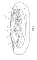
- FIG. 1illustrates a perspective view of one embodiment of a lighting system
- FIG. 2illustrates a cross-section view through line 2 - 2 of the lighting system 10 of FIG. 1 ;
- FIG. 3illustrates a flowchart of one embodiment of a method of lighting a display.
- FIG. 1illustrates a perspective view of one embodiment of a lighting system 10 .
- FIG. 2illustrates a cross-section view through line 2 - 2 of the lighting system 10 of FIG. 1 .
- the lighting system 10comprises a motor 12 , a lighting element 14 , a pointer 16 , a display 18 , a lens 20 , a coating 22 , and a cap 24 .
- the lighting system 10may comprise a portion of a vehicle 26 such as an analog instrument cluster gauge.
- the display 18may comprise an applique, such as a vehicle gauge display, and may comprise first and second opposed sides 18 a and 18 b .
- the motor 12may be disposed on the second opposed side 18 b of the display 18 for moving the pointer 16 relative to the display 18 .
- the motor 12may comprise a shaftless stepper motor comprising a shaftless portion 12 a .
- the shaftless portion 12 amay comprise an opening.
- a hollow shaft 16 a of the pointer 16may extend from the first opposed side 18 a of the display 18 , through an opening 18 c in the display 18 to the second opposed side 18 b of the display 18 , and be attached within and to the shaftless portion 12 a of the motor 12 .
- the motor 12moves the shaft 16 a of the pointer 16 thereby moving the pointer dial 16 b , disposed on the first opposed side 18 a of the display 18 , relative to the display 18 .
- the motor 12may move the pointer 16 using other mechanisms such as through magnetism using magnets, or through other connected members disposed between the pointer 16 and the motor 12 .
- the lighting element 14may be disposed within the shaftless portion 12 a of the shaftless stepper motor 12 on the second opposed side 18 b of the display 18 for transmitting light 14 a to light the shaft 16 a of the pointer 16 thereby lighting the attached hollow pointer dial 16 b of the pointer 16 .
- the lighting element 14may comprise a light-emitting diode or another type of lighting element 14 for lighting the pointer 16 .
- the lens 20may be disposed on the first opposed side 18 a of the display 18 .
- the lens 20may be transparent.
- the pointer dial 16 b of the pointer 16may be disposed between the first opposed side 18 a of the display 18 and the lens 20 .
- the cap 24may be attached to the lens 20 centered over the shaft 16 a of the pointer 16 on the first opposed side 18 a of the display 18 .
- the coating 22is disposed on an underside of the lens 20 a facing the pointer 16 and the display 18 .
- the coating 22is made of a material which when excited by light 28 emits light 30 onto the display 18 creating a shadow 16 c of the pointer 16 on the display 18 .
- the coating 22may be made of a material which comprises a decay rate which provides a ghosting effect by creating the trailing moving shadow 16 c of the pointer 16 on the display 18 .
- the material of the coating 22may be chosen to have a certain decay rate to provide the desired amount of ghosting.
- the decay rateis greater than 0 seconds and less than one second. In other embodiments, the decay rate may vary.
- the coating 22is made of Phosphorous. In other embodiments, the coating 22 may be made of any material which provides the desired amount of ghosting.
- FIG. 3illustrates a flowchart of one embodiment of a method 140 of lighting a display.
- the method 140may utilize any of the embodiments of the system 10 of FIGS. 1 and 2 disclosed herein.
- a pointer at least partially disposed on a first side of a displaymay be moved relative to the display with a motor disposed on a second side of the display.
- the displaymay comprise a portion of a vehicle such as an analog vehicle instrument cluster gauge. In other embodiments, the display may comprise varying types of displays.
- the second side of the displaymay be opposed to the first side of the display.
- the motormay comprise a shaftless stepper motor. In other embodiments, the motor may vary.
- the pointermay be lit with a lighting element disposed within the motor on the second side of the display.
- the lighting elementmay comprise a light-emitting diode disposed within a shaftless portion of the shaftless stepper motor.
- step 146light may be transmitted from the pointer into a coating disposed on an underside of a lens facing the pointer and the display.
- the lensmay be transparent and disposed on the first side of the display with the pointer at least partially disposed between the lens and the first side of the display.
- step 148the coating may be excited with the transmitted light from the pointer, and light may be emitted from the coating onto the first side of the display to provide a ghosting effect by creating a trailing moving shadow of at least a portion of the pointer on the display.
- the material of the coatingmay have been chosen based on its decay rate to provide the desired ghosting effect.
- the coatingmay be made of Phosphorous or any other type of material having a decay rate to provide the desired ghosting effect.
- one or more steps of the method 140may be altered in substance or order, not followed, or one or more additional steps may be followed.
- One or more embodiments of the disclosuremay reduce one or more issues experienced by one or more current systems or methods by providing a ghosting effect for a pointer of an instrument on a display using an inexpensive coating as opposed to a more expensive and complicated mechanical disc segment system, or other type of system, which is more prone to break down.
- One or more embodiments of the disclosuremay also have additional benefits over one or more other existing systems and methods.
Landscapes
- Engineering & Computer Science (AREA)
- Chemical & Material Sciences (AREA)
- Combustion & Propulsion (AREA)
- Transportation (AREA)
- Mechanical Engineering (AREA)
- Physics & Mathematics (AREA)
- General Physics & Mathematics (AREA)
- Details Of Measuring Devices (AREA)
- Instrument Panels (AREA)
- Indicating Measured Values (AREA)
- Planar Illumination Modules (AREA)
- Illuminated Signs And Luminous Advertising (AREA)
Abstract
Description
Claims (20)
Priority Applications (3)
| Application Number | Priority Date | Filing Date | Title |
|---|---|---|---|
| US13/588,401US8727549B2 (en) | 2012-08-17 | 2012-08-17 | Radar effect system and method for instrument cluster gauge |
| DE102013108834.1ADE102013108834A1 (en) | 2012-08-17 | 2013-08-15 | Radar effect system and method for a meter in a combination instrument |
| JP2013169189AJP5520410B2 (en) | 2012-08-17 | 2013-08-16 | Radar effect apparatus and method for instrument cluster gauge |
Applications Claiming Priority (1)
| Application Number | Priority Date | Filing Date | Title |
|---|---|---|---|
| US13/588,401US8727549B2 (en) | 2012-08-17 | 2012-08-17 | Radar effect system and method for instrument cluster gauge |
Publications (2)
| Publication Number | Publication Date |
|---|---|
| US20140049938A1 US20140049938A1 (en) | 2014-02-20 |
| US8727549B2true US8727549B2 (en) | 2014-05-20 |
Family
ID=50029681
Family Applications (1)
| Application Number | Title | Priority Date | Filing Date |
|---|---|---|---|
| US13/588,401Expired - Fee RelatedUS8727549B2 (en) | 2012-08-17 | 2012-08-17 | Radar effect system and method for instrument cluster gauge |
Country Status (3)
| Country | Link |
|---|---|
| US (1) | US8727549B2 (en) |
| JP (1) | JP5520410B2 (en) |
| DE (1) | DE102013108834A1 (en) |
Cited By (1)
| Publication number | Priority date | Publication date | Assignee | Title |
|---|---|---|---|---|
| US20130215594A1 (en)* | 2010-11-16 | 2013-08-22 | Yazaki Corporation | Illuminating structure of meter apparatus |
Families Citing this family (1)
| Publication number | Priority date | Publication date | Assignee | Title |
|---|---|---|---|---|
| US9534941B2 (en)* | 2014-08-21 | 2017-01-03 | Visteon Global Technologies, Inc. | Bar graph implementation with a paddle-style pointer |
Citations (19)
| Publication number | Priority date | Publication date | Assignee | Title |
|---|---|---|---|---|
| US2721808A (en) | 1951-11-14 | 1955-10-25 | Gen Electric | Electroluminescent cell |
| US2858632A (en) | 1955-06-27 | 1958-11-04 | Gen Motors Corp | Panel illumination |
| US3219008A (en) | 1959-09-08 | 1965-11-23 | Sylvania Electric Prod | Electroluminescent instrument lighting |
| US3776176A (en) | 1972-03-15 | 1973-12-04 | Master Electronics Corp | Indicator device which can be illuminated |
| US4860170A (en) | 1983-07-08 | 1989-08-22 | Yazaki Corporation | Pointer illuminating structure in measuring instrument |
| US4882659A (en) | 1988-12-21 | 1989-11-21 | Delco Electronics Corporation | Vacuum fluorescent display having integral backlit graphic patterns |
| US4959759A (en) | 1989-08-04 | 1990-09-25 | Delco Electronics Corporation | Automotive instrument display having a thickfilm electroluminescent lightpipe pointer |
| US4970400A (en) | 1987-10-02 | 1990-11-13 | Yazaki Corporation | Illuminated meter |
| US5319527A (en) | 1992-11-20 | 1994-06-07 | Delco Electronics Corporation | Illuminated instrumentation display |
| US5607222A (en) | 1995-08-21 | 1997-03-04 | Woog; Gunter | Low power illumination device |
| US5920150A (en) | 1995-01-25 | 1999-07-06 | Northern Engraving Corporation | Fluorescent automotive display panel |
| US5997161A (en) | 1997-12-09 | 1999-12-07 | General Motors Corporation | Black light instrument cluster assembly |
| US6379015B2 (en) | 1998-03-21 | 2002-04-30 | Mannesmann Vdo Ag | Indicating instrument with an illuminated pointer disposed behind the dial |
| US6990922B2 (en) | 2001-10-31 | 2006-01-31 | Toyoda Gosei Co., Ltd. | Indication system of meter part |
| US20060072005A1 (en)* | 2004-10-06 | 2006-04-06 | Thomas-Wayne Patty J | Method and apparatus for 3-D electron holographic visual and audio scene propagation in a video or cinematic arena, digitally processed, auto language tracking |
| US20080202408A1 (en) | 2007-02-23 | 2008-08-28 | Continental Automotive Systems Us, Inc. | Illuminated instrument cluster |
| US20090272313A1 (en) | 2008-03-07 | 2009-11-05 | Ballard Claudio R | Analog-style instrumentation display with color-changing pointer |
| US7665413B2 (en) | 2007-04-27 | 2010-02-23 | Continental Automotive Systems Us, Inc. | Illuminated hub pointer |
| US20100064962A1 (en) | 2008-09-17 | 2010-03-18 | Birman Vyacheslav B | Flood illuminated cluster with telltales |
- 2012
- 2012-08-17USUS13/588,401patent/US8727549B2/ennot_activeExpired - Fee Related
- 2013
- 2013-08-15DEDE102013108834.1Apatent/DE102013108834A1/ennot_activeWithdrawn
- 2013-08-16JPJP2013169189Apatent/JP5520410B2/enactiveActive
Patent Citations (21)
| Publication number | Priority date | Publication date | Assignee | Title |
|---|---|---|---|---|
| US2721808A (en) | 1951-11-14 | 1955-10-25 | Gen Electric | Electroluminescent cell |
| US2858632A (en) | 1955-06-27 | 1958-11-04 | Gen Motors Corp | Panel illumination |
| US3219008A (en) | 1959-09-08 | 1965-11-23 | Sylvania Electric Prod | Electroluminescent instrument lighting |
| US3776176A (en) | 1972-03-15 | 1973-12-04 | Master Electronics Corp | Indicator device which can be illuminated |
| US4860170A (en) | 1983-07-08 | 1989-08-22 | Yazaki Corporation | Pointer illuminating structure in measuring instrument |
| US4970400A (en) | 1987-10-02 | 1990-11-13 | Yazaki Corporation | Illuminated meter |
| US4882659A (en) | 1988-12-21 | 1989-11-21 | Delco Electronics Corporation | Vacuum fluorescent display having integral backlit graphic patterns |
| US4959759A (en) | 1989-08-04 | 1990-09-25 | Delco Electronics Corporation | Automotive instrument display having a thickfilm electroluminescent lightpipe pointer |
| US5319527A (en) | 1992-11-20 | 1994-06-07 | Delco Electronics Corporation | Illuminated instrumentation display |
| US5920150A (en) | 1995-01-25 | 1999-07-06 | Northern Engraving Corporation | Fluorescent automotive display panel |
| US5607222A (en) | 1995-08-21 | 1997-03-04 | Woog; Gunter | Low power illumination device |
| US5997161A (en) | 1997-12-09 | 1999-12-07 | General Motors Corporation | Black light instrument cluster assembly |
| US6379015B2 (en) | 1998-03-21 | 2002-04-30 | Mannesmann Vdo Ag | Indicating instrument with an illuminated pointer disposed behind the dial |
| US6990922B2 (en) | 2001-10-31 | 2006-01-31 | Toyoda Gosei Co., Ltd. | Indication system of meter part |
| US20060072005A1 (en)* | 2004-10-06 | 2006-04-06 | Thomas-Wayne Patty J | Method and apparatus for 3-D electron holographic visual and audio scene propagation in a video or cinematic arena, digitally processed, auto language tracking |
| US20080202408A1 (en) | 2007-02-23 | 2008-08-28 | Continental Automotive Systems Us, Inc. | Illuminated instrument cluster |
| US7665413B2 (en) | 2007-04-27 | 2010-02-23 | Continental Automotive Systems Us, Inc. | Illuminated hub pointer |
| US20090272313A1 (en) | 2008-03-07 | 2009-11-05 | Ballard Claudio R | Analog-style instrumentation display with color-changing pointer |
| US8125346B2 (en)* | 2008-03-07 | 2012-02-28 | Veedims, Llc | Analog-style instrumentation display with color-changing pointer |
| US20100064962A1 (en) | 2008-09-17 | 2010-03-18 | Birman Vyacheslav B | Flood illuminated cluster with telltales |
| US8261686B2 (en)* | 2008-09-17 | 2012-09-11 | Continental Automotive Systems Us, Inc. | Flood illuminated cluster with telltales |
Cited By (2)
| Publication number | Priority date | Publication date | Assignee | Title |
|---|---|---|---|---|
| US20130215594A1 (en)* | 2010-11-16 | 2013-08-22 | Yazaki Corporation | Illuminating structure of meter apparatus |
| US8905564B2 (en)* | 2010-11-16 | 2014-12-09 | Yazaki Corporation | Illuminating structure of meter apparatus |
Also Published As
| Publication number | Publication date |
|---|---|
| JP2014038102A (en) | 2014-02-27 |
| US20140049938A1 (en) | 2014-02-20 |
| JP5520410B2 (en) | 2014-06-11 |
| DE102013108834A1 (en) | 2014-02-20 |
Similar Documents
| Publication | Publication Date | Title |
|---|---|---|
| CN107585089B (en) | Vehicle bulb | |
| US20080186155A1 (en) | Persistence of Vision Display | |
| WO2006002852A3 (en) | Information display system for aircraft | |
| CN102132134A (en) | One led illuminating instrument cluster | |
| CN106195847A (en) | atmosphere lamp for vehicle | |
| US20110182052A1 (en) | Pointer structure of an instrument cluster | |
| US8727549B2 (en) | Radar effect system and method for instrument cluster gauge | |
| US9746351B2 (en) | Light conductor device and meter device including the same | |
| US10156337B2 (en) | Light device, especially a signal lamp, for motor vehicles | |
| US8757824B2 (en) | Pointer of an instrument driven with a shaftless stepper motor containing a lighting mechanism for lighting the pointer | |
| RU2008139910A (en) | PORTABLE NAVIGATION DEVICE | |
| US8379043B1 (en) | Methods and apparatus for displaying information on the inside of a windshield | |
| JP2009198465A (en) | Pointer instrument | |
| CN102582512A (en) | System and method for controlling change of background light of combination instrument of automobile along with automobile speed | |
| US20140009957A1 (en) | Light guide for an instrument cluster | |
| CN101941397B (en) | Pattern dynamic display device on car wheel cover disc or hub | |
| WO2010017910A3 (en) | Backlit graduated counter including means for super-illuminating part of the graduations | |
| US9829353B2 (en) | Instrument panel for motor vehicles and method of illumination | |
| US20040145885A1 (en) | Illuminative device for gauge face | |
| CN204937203U (en) | Bearing circle | |
| US9404774B2 (en) | Instrument panel assembly with variable length pointer | |
| CN110520670B (en) | Vehicle lighting device comprising a flexible OLED associated with an electromechanical deformation device | |
| EP1947425A1 (en) | Velocity indicator for vehicle | |
| EP2779149A1 (en) | Method and intensity adjustment system for intensity adjustment of a vehicle display | |
| JP2007240243A (en) | Vehicle-use display device |
Legal Events
| Date | Code | Title | Description |
|---|---|---|---|
| AS | Assignment | Owner name:VISTEON GLOBAL TECHNOLOGIES, INC, MICHIGAN Free format text:ASSIGNMENT OF ASSIGNORS INTEREST;ASSIGNOR:FARELL, JAMES PAUL;REEL/FRAME:028805/0812 Effective date:20120817 | |
| AS | Assignment | Owner name:CITIBANK., N.A., AS ADMINISTRATIVE AGENT, NEW YORK Free format text:SECURITY INTEREST;ASSIGNORS:VISTEON CORPORATION, AS GRANTOR;VISTEON GLOBAL TECHNOLOGIES, INC., AS GRANTOR;REEL/FRAME:032713/0065 Effective date:20140409 | |
| STCF | Information on status: patent grant | Free format text:PATENTED CASE | |
| FEPP | Fee payment procedure | Free format text:PAYOR NUMBER ASSIGNED (ORIGINAL EVENT CODE: ASPN); ENTITY STATUS OF PATENT OWNER: LARGE ENTITY | |
| FEPP | Fee payment procedure | Free format text:SURCHARGE FOR LATE PAYMENT, LARGE ENTITY (ORIGINAL EVENT CODE: M1554) | |
| MAFP | Maintenance fee payment | Free format text:PAYMENT OF MAINTENANCE FEE, 4TH YEAR, LARGE ENTITY (ORIGINAL EVENT CODE: M1551) Year of fee payment:4 | |
| FEPP | Fee payment procedure | Free format text:MAINTENANCE FEE REMINDER MAILED (ORIGINAL EVENT CODE: REM.); ENTITY STATUS OF PATENT OWNER: LARGE ENTITY | |
| LAPS | Lapse for failure to pay maintenance fees | Free format text:PATENT EXPIRED FOR FAILURE TO PAY MAINTENANCE FEES (ORIGINAL EVENT CODE: EXP.); ENTITY STATUS OF PATENT OWNER: LARGE ENTITY | |
| STCH | Information on status: patent discontinuation | Free format text:PATENT EXPIRED DUE TO NONPAYMENT OF MAINTENANCE FEES UNDER 37 CFR 1.362 | |
| FP | Lapsed due to failure to pay maintenance fee | Effective date:20220520 |