US8727536B2 - Polarization conversion system and method for projecting polarization encoded imagery - Google Patents
Polarization conversion system and method for projecting polarization encoded imageryDownload PDFInfo
- Publication number
- US8727536B2 US8727536B2US12/118,640US11864008AUS8727536B2US 8727536 B2US8727536 B2US 8727536B2US 11864008 AUS11864008 AUS 11864008AUS 8727536 B2US8727536 B2US 8727536B2
- Authority
- US
- United States
- Prior art keywords
- polarization
- light
- conversion system
- state
- lens
- Prior art date
- Legal status (The legal status is an assumption and is not a legal conclusion. Google has not performed a legal analysis and makes no representation as to the accuracy of the status listed.)
- Active, expires
Links
Images


Classifications
- G—PHYSICS
- G02—OPTICS
- G02B—OPTICAL ELEMENTS, SYSTEMS OR APPARATUS
- G02B5/00—Optical elements other than lenses
- G02B5/30—Polarising elements
- G—PHYSICS
- G02—OPTICS
- G02B—OPTICAL ELEMENTS, SYSTEMS OR APPARATUS
- G02B30/00—Optical systems or apparatus for producing three-dimensional [3D] effects, e.g. stereoscopic images
- G02B30/20—Optical systems or apparatus for producing three-dimensional [3D] effects, e.g. stereoscopic images by providing first and second parallax images to an observer's left and right eyes
- G02B30/22—Optical systems or apparatus for producing three-dimensional [3D] effects, e.g. stereoscopic images by providing first and second parallax images to an observer's left and right eyes of the stereoscopic type
- G02B30/25—Optical systems or apparatus for producing three-dimensional [3D] effects, e.g. stereoscopic images by providing first and second parallax images to an observer's left and right eyes of the stereoscopic type using polarisation techniques
- H—ELECTRICITY
- H04—ELECTRIC COMMUNICATION TECHNIQUE
- H04N—PICTORIAL COMMUNICATION, e.g. TELEVISION
- H04N13/00—Stereoscopic video systems; Multi-view video systems; Details thereof
- H04N13/30—Image reproducers
- H04N13/332—Displays for viewing with the aid of special glasses or head-mounted displays [HMD]
- H04N13/337—Displays for viewing with the aid of special glasses or head-mounted displays [HMD] using polarisation multiplexing
- G—PHYSICS
- G02—OPTICS
- G02B—OPTICAL ELEMENTS, SYSTEMS OR APPARATUS
- G02B26/00—Optical devices or arrangements for the control of light using movable or deformable optical elements
- G02B26/007—Optical devices or arrangements for the control of light using movable or deformable optical elements the movable or deformable optical element controlling the colour, i.e. a spectral characteristic, of the light
- G02B26/008—Optical devices or arrangements for the control of light using movable or deformable optical elements the movable or deformable optical element controlling the colour, i.e. a spectral characteristic, of the light in the form of devices for effecting sequential colour changes, e.g. colour wheels
- G—PHYSICS
- G02—OPTICS
- G02B—OPTICAL ELEMENTS, SYSTEMS OR APPARATUS
- G02B30/00—Optical systems or apparatus for producing three-dimensional [3D] effects, e.g. stereoscopic images
- G—PHYSICS
- G02—OPTICS
- G02B—OPTICAL ELEMENTS, SYSTEMS OR APPARATUS
- G02B30/00—Optical systems or apparatus for producing three-dimensional [3D] effects, e.g. stereoscopic images
- G02B30/20—Optical systems or apparatus for producing three-dimensional [3D] effects, e.g. stereoscopic images by providing first and second parallax images to an observer's left and right eyes
- G02B30/22—Optical systems or apparatus for producing three-dimensional [3D] effects, e.g. stereoscopic images by providing first and second parallax images to an observer's left and right eyes of the stereoscopic type
- G02B30/24—Optical systems or apparatus for producing three-dimensional [3D] effects, e.g. stereoscopic images by providing first and second parallax images to an observer's left and right eyes of the stereoscopic type involving temporal multiplexing, e.g. using sequentially activated left and right shutters
- G—PHYSICS
- G03—PHOTOGRAPHY; CINEMATOGRAPHY; ANALOGOUS TECHNIQUES USING WAVES OTHER THAN OPTICAL WAVES; ELECTROGRAPHY; HOLOGRAPHY
- G03B—APPARATUS OR ARRANGEMENTS FOR TAKING PHOTOGRAPHS OR FOR PROJECTING OR VIEWING THEM; APPARATUS OR ARRANGEMENTS EMPLOYING ANALOGOUS TECHNIQUES USING WAVES OTHER THAN OPTICAL WAVES; ACCESSORIES THEREFOR
- G03B21/00—Projectors or projection-type viewers; Accessories therefor
- H—ELECTRICITY
- H04—ELECTRIC COMMUNICATION TECHNIQUE
- H04N—PICTORIAL COMMUNICATION, e.g. TELEVISION
- H04N13/00—Stereoscopic video systems; Multi-view video systems; Details thereof
- H04N13/30—Image reproducers
- H—ELECTRICITY
- H04—ELECTRIC COMMUNICATION TECHNIQUE
- H04N—PICTORIAL COMMUNICATION, e.g. TELEVISION
- H04N13/00—Stereoscopic video systems; Multi-view video systems; Details thereof
- H04N13/30—Image reproducers
- H04N13/332—Displays for viewing with the aid of special glasses or head-mounted displays [HMD]
- H04N13/341—Displays for viewing with the aid of special glasses or head-mounted displays [HMD] using temporal multiplexing
- G—PHYSICS
- G02—OPTICS
- G02B—OPTICAL ELEMENTS, SYSTEMS OR APPARATUS
- G02B13/00—Optical objectives specially designed for the purposes specified below
Definitions
- the disclosed embodimentsrelate generally to projection of polarization-encoded images and, more specifically, to a polarization conversion system and method for transmitting polarization-encoded imagery to a projection screen.
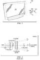
- FIG. 1is a schematic diagram illustrating an exemplary polarization-preserving display system 100 .
- the display system 100includes a projection screen 102 and polarization filtering eyewear 104 .
- Stereoscopic three-dimensional (3D) imageryis observed using a single polarization-preserving screen 102 sequentially displaying left and right perspective imagery, with polarization filtering eyewear 104 .
- the polarization filtering eyewear 104contains two lenses 106 and 108 of alternately orthogonal polarization.
- 3D imagerycan be synthesized using polarization control at the projector to encode, and polarization filtering eyewear to decode the left and right perspective imagery (See, e.g., commonly-owned U.S. Pat. No. 4,792,850, entitled “Method and system employing a push-pull liquid crystal modulator,” to Lenny Lipton et al. and U.S. patent application Ser. No. 11/424,087 entitled “Achromatic Polarization Switches,” filed Jun. 14, 2006, both of which are herein incorporated by reference in their entirety for all purposes).
- FIG. 2A conventional implementation of polarization control after the projection lens is shown in FIG. 2 .
- Nearly-parallel raysemerge from the output of the lens, appearing to originate from a pupil inside of the lens, and converge to form spots on a distant screen.
- Ray bundles A, B, and C in FIG. 2are bundles forming spots at the bottom, center, and top of a projection screen.
- the light emerging from the projection lensis randomly polarized, depicted in FIG. 2 as both S- and P-polarized light.
- the lightpasses through a linear polarizer, resulting in a single polarization state after the polarizer.
- the orthogonal polarization stateis absorbed (or reflected), and the light flux after the polarizer is less than 50% of the original flux (resulting in a dimmer final image).
- the polarization switchis synchronized with the image frame, and the polarization state emerging from the polarization switch is alternated, producing images of alternately orthogonal polarization at the screen.
- Polarization selective eyewear 104allows images of one polarization to pass to the left eye, and images of the orthogonal polarization to pass to the right eye. By presenting different images to each eye, 3D imagery can be synthesized.
- This systemis currently in use in movie theatres.
- this system designsuffers from having more than 50% of the light absorbed by the polarizer, and thus the resulting image is typically more than 50% dimmer than that of a typical 2D theatre.
- time-sequential stereoscopic 3Dfurther reduces the brightness by more than 50%.
- the dimmer imagecan therefore limit the size of the theatre used for 3D applications and/or provides a less desirable viewing experience for the audience.
- a polarization conversion systemseparates light from an unpolarized image source into a first state of polarization (SOP) and an orthogonal second SOP, and directs the polarized light on first and second light paths.
- SOPstate of polarization
- a polarization modulatortemporally modulates the light on the first and second light paths to first and second output states of polarization.
- First and second projection lensesdirect light on the first and second light paths toward a projection screen to form substantially overlapping polarization encoded images, much brighter than the referenced prior art system.
- the polarization-encoded imagesmay be viewed using eyewear with appropriate polarization filters
- a polarization conversion system for transmitting polarization encoded imagery to a projection screenincludes a first projection lens, a second projection lens, a polarization beam splitter (PBS), a reflecting element, and a polarization modulator.
- the PBSis operable to transmit light of a first polarization state toward the first projection lens on a first light path, and is further operable to reflect light of a second polarization state toward a second light path.
- the reflecting elementis located on the second light path and is operable to reflect light toward the second projection lens.
- the polarization modulatormay be located on the first and second light paths.
- the first and second projection lensesare operable to direct the polarization encoded images toward the projection screen.
- the polarization modulatormay be a single unit that is located on both the first and second light paths.
- the polarization modulatormay include a first polarization switch and a second polarization switch, each polarization switch being located on respective first and second light paths.
- the polarization switch(es)may be located before or after the projection lenses.
- a method for projecting polarization-encoded stereoscopic imagesincludes receiving unpolarized image source light at a polarization beam splitter.
- the methodincludes transmitting image source light of a first polarization state at the polarization beam splitter toward a projection lens located on a first light path.
- the methodalso includes reflecting image light of a second polarization state at the polarization beam splitter toward a second light path.
- the methodfurther includes reflecting light on the second light path toward a second projection lens.
- the methodadditionally includes rotating the state of polarization of light on one of the first and second light paths light to an orthogonal state of polarization.
- the methodfurther includes temporally modulating the state of polarization of the light on the first and second light paths between a first polarized output state and a second polarized output state.
- FIG. 1is a schematic diagram illustrating an exemplary polarization-preserving display system, in accordance with the present disclosure
- FIG. 2illustrates a known implementation of polarization control in a cinematic 3D system utilizing a polarization switch
- FIG. 3is a schematic diagram illustrating a first embodiment of a polarization conversion system (PCS), in accordance with the present disclosure
- FIG. 3Bis a schematic diagram illustrating a polarization converting and switching module, in accordance with the present disclosure
- FIG. 4is a schematic diagram illustrating a second embodiment of a PCS, in accordance with the present disclosure.
- FIG. 5is a schematic diagram illustrating a third embodiment of a PCS, in accordance with the present disclosure.
- FIG. 6is a schematic diagram illustrating a fourth embodiment of a PCS, in accordance with the present disclosure.
- FIG. 7is a schematic diagram illustrating a fifth embodiment of a PCS, in accordance with the present disclosure.
- FIG. 8is a schematic diagram illustrating a sixth embodiment of a PCS, in accordance with the present disclosure.
- FIG. 9is a schematic diagram illustrating a seventh embodiment of a PCS, in accordance with the present disclosure.
- FIG. 10is a schematic diagram illustrating an eighth embodiment of a PCS, in accordance with the present disclosure.
- FIG. 11is a schematic diagram of a ninth embodiment of a PCS, in accordance with the present disclosure.
- FIG. 12is a schematic diagram of a tenth embodiment of a PCS, in accordance with the present disclosure.
- FIG. 3is a schematic diagram illustrating a first embodiment of a polarization conversion system (PCS) 300 .
- PCS 300may include an image source 304 (e.g., from a light modulating panel or conventional film), initial relay lens 302 , polarizing beamsplitter (PBS) 310 , first and second relay lenses 306 , 308 , polarization switch 312 , fold mirror 318 , polarization converting and switching module 320 , and first and second projection lenses 328 , 330 , arranged as shown.
- image source 304e.g., from a light modulating panel or conventional film
- PBSpolarizing beamsplitter
- polarization converting and switching module 320may include polarization converter 322 and polarization switch 324 , and may optionally include a pre-polarizer 326 to improve contrast, all arranged as shown.
- Polarization converter 322is an optical component that is operable to transform an input state of polarization to an orthogonal state of polarization (e.g., a half wave plate).
- the first and second relay lenses 306 and 308are preferably symmetric about respective aperture stops 301 , 303 , respectively located after the polarization switch 312 and polarization converting and switching module 320 , providing substantially distortion-less images of the panel 304 at each image location 314 and 316 .
- the aperture stops 301 , 303may be located on the respective light paths 305 , 307 , immediately prior to the polarization switch 312 and polarization converting and switching module 320 .
- FIG. 3depicts an alternate location 332 for the polarization switch 312 in the first light path 306 , and an alternate location 334 for the polarization converting and switching module 320 in the second light path 308 .
- the polarization switches 312 , 324may instead be placed after the projection lens rather than prior to it. Such an embodiment may provide system contrast advantages. Note that it is not necessary that the half wave plate 322 is immediately adjacent the polarization switch 324 —the half wave plate 322 may be located anywhere in the light path between the PBS 310 and the polarization switch 324 .
- the positions of the polarization switch 312 and the polarization converting and switching module 320may be reversed such that the polarization switch 312 is located on the second light path 307 and the polarization converting and switching module 320 is located on the first light path 305 .
- panel 304e.g., a Digital Light Processing (DLP) panel from Texas Instruments or conventional film
- DLPDigital Light Processing
- the light sourcemay be, for example, a conventional UHP lamp, a xenon lamp, a light emitting diode light source, or in some embodiments, a light source taught in commonly-owned U.S. patent application Ser. No. 11/779,708, entitled “Light collector for projection systems,” filed Jul. 18, 2007, herein incorporated by reference.
- the unpolarized image source light from the panel 304is directed toward PBS 310 by initial relay lens 302 .
- the PBS 310may transmit P-polarized light on a first light path 305 , and reflect S-polarized light toward a second light path 307 .
- the P-polarized lightpasses through the polarization switch 312 , which operates to rotate the light passing through the switch 312 in alternating frames, similar to the bundles A, B, and C in FIG. 2 .
- the S-polarized light reflected by the PBS 310passes to a fold mirror 318 (or any optical component that serves to reflect light without changing the polarization state, e.g., a prism).
- the S-polarized lightthen passes through a polarization converting and switching module 320 .
- the polarization converter 322(which may be a half wave plate) preferably transforms substantially all visible wavelengths to the orthogonal polarization (in this case, from S- to P-polarized light).
- the now-P-polarized lightthen passes through polarization switch 324 .
- a pre-polarizer 326may be added before or after module 320 for higher contrast.
- the polarization switch 324 included in the polarization and switching module 320operates to create alternating orthogonal states in a manner substantially identical to the switch 312 in the first light path 305 .
- the polarization conversion system 300may form two separate images 314 and 316 of the panel 304 , each with magnification 1 ⁇ (i.e., the output images at 314 and 316 may be substantially the same size as the input image from panel 304 ). It should be appreciated that the magnification could be other than 1 ⁇ in this and other embodiments and that this magnification is provided as an example.
- First and second projection lenses 328 and 330respectively image the intermediate images 314 and 316 onto the projection screen 102 .
- the projection lenses 328 and 330are allowed to move laterally, such that the images on the screen 102 from the two optical paths 305 and 307 are superimposed, substantially overlapping, preferably with minimal keystone distortion.
- the resulting image of the system in FIG. 3is approximately two times brighter than the image at the screen 102 for the system in FIG. 2 .
- This systemmay also be applied to cinematic, professional and consumer applications such as home theatre and rear projection television (RPTV), assuming polarization-preserving screens 102 are utilized.
- RPTVhome theatre and rear projection television
- FIG. 4is a schematic diagram illustrating a second embodiment of a polarization conversion system (PCS) 400 .
- PCS 400provides a similar relay system to that shown in FIG. 3 , with an arrangement of components having substantially similar structure and function, except a glass prism 410 has been inserted into the second light path 407 , arranged as shown.
- Glass prism 410may be a high index glass prism.
- the glass prism 410allows the two images 414 and 416 of the panel 404 to be collocated substantially in a single plane, providing more convenient packaging and adjustment of the projection lenses 428 and 430 . It is preferable that the relay system 400 is designed such that rays from a single field point at the object (i.e., panel 404 ) produce a collimated bundle (all rays from a field point having the same angle) at the aperture stops 401 and 403 . This allows the insertion of the glass prism 410 at the aperture stop without affecting the lens 402 performance.
- the glass prism 410allows the two images 414 and 416 to be collocated.
- the polarization converting and switching module 420 and polarization switch 412may each have alternate locations 404 and 406 respectfully for each path, either before the projection lens or after the projection lens.
- FIG. 5is a schematic diagram illustrating a third embodiment of a polarization conversion system (PCS) 500 .
- FIG. 5provides a similar PCS 500 to that shown in FIG. 4 , except the polarization switch 412 of FIG. 4 has been replaced by a spinning wheel 550 operable to convert the polarized input to a set of temporally alternating orthogonally polarized output states.
- the spinning wheel 550may contain segments that transmit alternating orthogonal polarizations from a non-polarized input.
- the spinning wheel 550may be preceded by a fixed polarizer. The spinning wheel 550 may then contain segments that represent unitary polarization transformations (e.g. from a stack of retardation films).
- a binary polarization switching effectis desired, which according to this disclosure is optimally accomplished using elements with circular Eigenpolarizations. For instance, a true circular polarizer (versus, for example, a linear polarizer followed by a retarder, or retarder stack) will transmit a particular handedness (e.g. right or left) of circular state, regardless of wheel orientation.
- a fixed polarizercan be followed by a unitary polarization transforming element with circular Eigenpolarizations, or a pure circular retarder.
- a linear polarizercan be followed by a rotating wheel 550 that contains a combination of isotropic segments, as well as pure achromatic polarization rotating elements.
- a pure achromatic rotatorhas zero linear retardation (no optic axis), but has a desired amount of phase delay between orthogonal circular states. In this case, a ⁇ phase shift between circular Eigenstates will convert the input to the orthogonal linear output, regardless of wheel orientation.
- an analog wheelwill provide binary switching between orthogonal linear polarizations.
- Pure achromatic polarization rotatorsmay be fabricated using stacks of linear retarders.
- One design methodis to pair stacks with a particular symmetry arrangement. For instance, a stack that produces a particular retardation and rotation can be paired with an identical stack with reverse-order, or reverse-order reflected symmetry (See, e.g., Chapter 5 of Robinson et. al., P OLARIZATION E NGINEERING FOR LCD P ROJECTION , Wiley & Sons 2005, which is hereby incorporated by reference).
- a reverse order stackdoubles the net retardation while eliminating rotation, while the addition of reflection has the effect of doubling rotation while eliminating retardation.
- a stack designed to convert a O-oriented linear input to a ⁇ /4 oriented linear output (at all wavelengths of interest)can be designed, which in general contains linear retardation. However, when paired with the reverse-order-reflected stack, the net effect is zero retardation and the desired ⁇ /2 orientation transformation.
- Such transparent elementscan be laminated as segments on an isotropic disk to produce binary polarization switching with spinning wheel 550 .
- Table 1provides a design for an exemplary retarder stack exhibiting substantially achromatic rotation of ⁇ /2 having reverse-order-reflected symmetry. Note that this symmetry is a sufficient, but not necessary condition for achieving the desired polarization transformation. It is easily verified that the state of polarization after layer-6 is 45° linear, though the stack possesses linear retardation that is eliminated by the subsequent stack. In this example, all layers have a zero-order in-plane retardation of 1 ⁇ 2-wave (typically 240-270 nm to span the visible). It should be apparent that, in accordance with the present disclosure, other retarder combination designs may be employed that have different orientations and retardation profiles.
- light from the lower light path 505is P-polarized and passes through the isotropic segment 504 of the wheel 550 .
- the lightremains P-polarized through Image 2 516 , through the projection lens 530 , and onto the screen 102 .
- light in the upper path 507is S-polarized and passes through the rotator segment 506 of the wheel 550 .
- the S-polarized lightis rotated to P-polarized light by the wheel 550 , and passes through the projection lens 528 and onto the screen 102 as P-polarized light.
- the wheel 550is then synchronized with the video frames to produce images on a screen 102 with alternating polarization.
- Variations of the polarization statesare also possible, with each path producing circular polarization by addition of quarter-wave plates in the optical paths, or rotated linear polarization states (e.g., +/ ⁇ 45 degrees) by addition of rotators in each path.
- FIG. 6is a schematic diagram illustrating a fourth embodiment of a polarization conversion system (PCS) 600 .
- FIG. 6illustrates a PCS 600 where the magnification has been increased to 2 ⁇ (versus 1 ⁇ previously).
- the first half of the PCS 600including PBS 610 and path-matching glass prism 602 may be identical in structure and function to the components described in FIG. 4 .
- the second half of the PCS 600has been scaled by 2 to increase the focal length of the second half by 2.
- the PCS 600produces an image that is twice the size of the panel 604 , yet maintains the same f-number (or numerical aperture).
- a single relay lens 608may be used to provide an intermediate image
- a single projection lens 630e.g., a 70 mm cinema lens
- the polarization converting and switching module 620 and its alternate location 625are also shown.
- FIG. 7is a schematic diagram illustrating a fifth embodiment of a PCS 700 .
- FIG. 7depicts a similar PCS 700 to that shown in FIG. 6 , except the polarization converting and switching modules 620 of FIG. 6 have been replaced by the segmented wheel 750 (similar to the segmented wheel 550 described in FIG. 5 ).
- the segmented wheel 750 and an alternate segment wheel location 752are also indicated.
- a single projection lens 730can be utilized to image the intermediate image to the screen 102 .
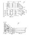
- FIG. 8is a schematic diagram illustrating a sixth embodiment of a PCS 800 .
- the PCS 800may include a panel 804 , an initial relay lens 802 , a PBS 810 , a polarization switch 812 on a first light path, a glass prism 814 with a reflector (e.g., a mirrored angled surface) 816 , a polarization converting and switching module 818 , and first and second projection lenses 820 and 822 , all arranged as shown.
- Polarization converting and switching module 818may have an optional pre-polarizer, a polarization rotator and a polarization switch, similar to the description of the polarization converting and switching module 320 of FIG. 3B .
- the projection lens system 800may form two separate images of the panel 304 , each with large magnification. This PCS 800 may also be applied to professional and consumer applications such as home theatre and RPTV, assuming polarization-preserving screens 102 are available.
- panel 804(such as a Digital Light Processing, or DLP, panel from Texas Instruments) is illuminated with randomly polarized light.
- light from the panel 804is projected to a screen 102 by first and second projection lenses 820 and 822 , which may be of the reverse telephoto type.
- the PBS 810transmits P-polarized light along a first light path, and reflects S-polarized light along a second light path.
- the P-polarized lightpasses through the polarization switch 812 and is rotated by the polarization switch 812 in alternating frames, similar to bundles A, B, and C in FIG. 2 .
- the S-polarized light reflected by the PBS 810passes to a prism 814 .
- the prism 814may contain an angled surface 816 that serves as a fold mirror. Reflection may be accomplished with total internal reflection, or by coating the hypotenuse with a mirror layer (e.g., silver).
- a mirror layere.g., silver
- the aperture stop 830may be located along the first light path before the polarization switch 812 , and/or along the second light path at some location (i.e., 832 ) before the prism structure 814 .
- collimated rayspass through the prism structure 814 without the introduction of aberrations.
- the S-polarized lightthen passes out of the prism 814 , through polarization converting and switching module 818 , and is rotated to P-polarized light.
- the polarization switch within polarization converting and switching module 818acts on P-polarized light, rotating the polarization of the ray bundles in alternating frames, in synchronization with the rotation of bundles in the non-mirror path.
- Two substantially identical second halves of the lenses 820 and 822project the two images onto the screen 102 .
- the polarizing beamsplitter 810 tiltmay be adjusted and/or the prism 808 tilt may be adjusted.
- the projection lens assemblymay as a whole, be allowed to move laterally, such that the images on the screen 102 from the first and second optical paths can be offset vertically for various theatre configurations.
- the first half lenses 820may be cut in the lower path to allow for light to pass clearly in the upper path, as is depicted in FIG. 8 .
- the resulting image of the system in FIG. 8is approximately two times brighter than the image at the screen 102 for the system in FIG. 2 .
- FIG. 9depicts a similar polarization conversion system 900 as in FIG. 8 , except that the polarization switch 812 has been replaced by a spinning wheel 902 .
- the wheel 902is segmented into two or more regions as described previously.
- light from the lower path 904is P-polarized and passes through the (e.g.) isotropic segment 901 of the wheel 902 .
- the lightremains P-polarized through the rest of the projection lens system 900 , and onto the screen 102 .
- light in the upper path 906is S-polarized and passes through the (e.g.) rotator segment 903 of the wheel 902 .
- the S-polarized lightis rotated to P-polarized light by the wheel 902 , and passes through the rest of the projection lens system 900 and onto the screen 102 as P-polarized light.
- the wheel 902is then synchronized with the video frames to produce images on screen 102 with alternating polarization.
- Variations of the polarization statesare also possible, with each path 904 and 906 producing circular polarization by addition of quarter wave plates (not shown) in the optical paths, or rotated linear polarization states (e.g. +/ ⁇ 45 degrees) by addition of rotators in each path.
- FIG. 10depicts a similar polarization conversion system 1000 to that of FIG. 9 .
- the structure and function of the components of the PCS 1000are substantially similar to that of the PCS 900 , except two rotator wheels 1002 and 1004 are implemented instead of one, in part, to ease packaging constraints near the prism 808 .
- the rotator wheels 1002 and 1004may operate in synchronization with each other.
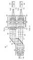
- FIG. 11is a schematic diagram of an exemplary cinematic PCS system 1100 that implements zoom lenses.
- Cinematic PCS system 1100may include a panel 1102 , a telecentric objective 1104 (i.e., an initial relay lens), a polarization beam splitter (PBS) 1106 , first and second aperture stops 1108 , 1110 , first and second mechanically compensated afocal zooms 1112 , 1132 , reflecting element 1130 , rotator 1136 , and first and second z-screens 1124 , 1138 .
- PBSpolarization beam splitter
- s- and p-polarized light from panel 1102passes through telecentric objective 1104 toward PBS 1106 .
- Telecentric objective 1104is used to maintain collimated light at the PBS 1106 for all zoom settings.
- PBS 1106may be a cube or wire grid plate, or any other PBS known in the art.
- p-polarized lightis transmitted through the PBS 1106 toward a first direction, while s-polarized light is reflected at the PBS 1106 toward a second direction.
- zoom 1112may include various elements having positive and negative optical powers.
- the afocal zoomcan be mechanically compensated or optically compensated, for instance, using techniques in zoom lens design from “Modern Optical Engineering” by Warren Smith, 1990, McGraw-Hill herein incorporated by reference.
- Zoom 1112 in this exemplary embodimentmay have, on a light path, a fixed optical element such as concave lens 1114 , followed by moving elements convex lens 1116 and concave lens 1118 , followed by another fixed element, convex lens 1120 .
- a fixed optical elementsuch as concave lens 1114
- moving elements convex lens 1116 and concave lens 1118followed by another fixed element, convex lens 1120 .
- convex lensesare represented by lines with dots at either end, and generally have positive optical power and may include single or multiple optical elements to provide such positive optical power.
- concave lenses(represented by concave graphics) generally have negative optical power and may include single or multiple optical elements to provide such negative optical power.
- the moving elements 1122may move along the optical axis to adjust the zoom of the image as desired. Light from zoom 1112 then passes through a first z-screen 1124 and then toward a screen 1150 to form a first image.
- S-polarized light from PBS 1106 that is reflected toward the second directionpasses through aperture stop 1110 . Subsequently, the light is reflected by about 90 degrees by a reflecting element 1130 , such as a right angle prism with mirror 1130 . The s-polarized light then passes through second mechanically compensated afocal zoom 1132 .
- Zoom 1132may employ a similar structure and operate in a similar way to the structure and operation described for zoom 1112 . Of course, the moving elements 1134 may be adjusted differently, to provide a different zoom, as desired.
- S-polarized light from zoom 1132may then pass through rotator 1136 , which may be an achromatic half wave plate.
- Rotator 1136functions to rotate the s-polarized light into p-polarized light.
- the p-polarized light on the second light paththen passes through second z-screen 1138 , and then toward screen 1150 , to form a second image.
- the first and second imagesare overlaid at screen 1150 .
- Polarizing beamsplitterThe exemplary PBS shown in FIG. 3 through FIG. 12 is depicted as a PBS plate.
- This PBS platemay be constructed using a wire grid layer on glass (e.g., Proflux polarizer from Moxtek in Orem, Utah), polarization recycling film (e.g., Double Brightness Enhancing Film from 3M in St. Paul, Minn.), polarization recycling film on glass (for flatness), or a multi-dielectric layer on glass.
- the PBScould also be implemented as a glass cube (with wire grid, polarization recycling film, or dielectric layers along the diagonal).
- Adjustment of image locationIn FIG. 3 , the primary adjustment of image location for each path is lateral displacement of the projection lenses 328 and 330 . Additional adjustment of the image location may be achieved by adjusting the PBS 310 and/or the mirror 318 . In FIG. 4 and FIG. 5 , the primary adjustment of the image location for each path is the lateral displacement of the projection lenses 428 / 430 and 528 / 530 . Additional fine adjustment of the image location may be achieved by laterally displacing and tilting the prism structure 402 . In FIG. 6 and FIG. 7 , adjustment of the image overlay can be achieved by fine adjustment of the prism location and tilt. Adjustment of the image location on-screen may be accomplished by lateral displacement of the projection lens ( 630 or 730 ).
- adjustment of the image overlaymay be accomplished by tilting the polarizing beamsplitter ( 810 , 910 , or 1010 ) and/or tilting the prism ( 814 , 914 , or 1014 ).
- Adjustment of the aforementioned components (PBS, mirror and/or projection lenses) to control image locationmay be accomplished using electro-mechanical actuators.
- Feedback control systems and sensorsmay provide processing, control and drive instructions to the actuators in order to position the location of the first and second images on the screen 102 .
- the polarization switchmay be a circular polarization switch or a linear polarization switch (e.g., Z-screen of U.S. Pat. No. 4,792,850 to Lipton, or one of the Achromatic Polarization Switches as disclosed in U.S. patent application Ser. No. 11/424,087, all of which are previously incorporated by reference).
- Another technique disclosed herein for switching polarizationincludes using a rotating polarization wheel, as shown in the embodiments taught with reference to FIGS. 5 , 7 , 9 and 10 .
- the polarization switch 312can be any switch that alternates between orthogonal polarization states, such that the eyewear 104 can decode the states and send the appropriate imagery to each eye.
- the polarization switchcan be split between the two paths (e.g. to increase yield of the device).
- All transmissive elementsmay be anti-reflection coated to provide high transmission and low reflection. Reflections from transmissive elements can cause stray light in the system, which degrades contrast and/or produces disturbing artifacts in the final image. Non-optical surfaces (e.g., the prism sides) can be painted black to enhance contrast. Additional absorptive polarizers may be placed after the PBS 310 in either path to control polarization leakage and improve the final image contrast.
- Fold mirror and polarization purityThe fold mirror may be replaced with a PBS element (e.g., wire grid plate) in FIG. 3 through FIG. 10 .
- a purer polarizationmay be maintained after the folding element and could negate the need for an input polarizer on the polarization switch.
- light reflected at the angled face of the prismmay use total internal reflection for the reflecting mechanism. Dielectric and metal layers may also be added to the prism at the angled face to enhance reflection and preserve polarization purity.
- FIGS. 3-10illustrate the use of projection lenses with reverse telephoto construction
- the polarization conversion systems disclosed hereinare not limited to using such projection lenses.
- a reverse telephoto lens in a compact formis described in U.S. Pat. No. 6,473,242 ('242 patent), which is hereby incorporated by reference.
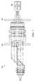
- FIG. 12illustrates a tenth embodiment of the polarization conversion system 1200 that provides a polarization beam splitter internal to the projection lens, differing from the reverse telephoto lens design of the '242 patent.
- the polarizing beamsplitter 1210is incorporated into the lens ( 1230 a , 1230 b and 1230 c ) at the aperture stop, and two optical paths 1212 and 1214 exist for overlaying the two polarization states out of the projector.
- the mirror 1216 , rotator 1218 and polarization switches 1220 and 1222are located after the second half of the projection lens ( 1230 b and 1230 c ), between the lens 1230 and silver screen.
- the lens prescriptionhas been modified to produce collimated rays from each field point at the aperture stop. This modification results two particular differences from the lens described in the '242 patent.
- the lens described hereinhas no such restriction on r4 (e.g., r4/f could be 0.6 in this instance).
- the lens described hereinmay include a third lens having negative refractive power. As a consequence of the modification, the lens described herein is no longer reverse telephoto.
- a PBS 1210 , mirror 1216 , and polarization switch(es) 1220 , 1222are included for the PCS function. The mirror 1216 can be tilted to align the two images at the screen.
- a right-angle glass prismmay substitute the mirror 1216 .
- the PBS 1210can be replaced with a PBS cube.
- the polarization switchesare placed at the output of the lens for highest polarization purity. One or two polarization switches may be used at the output. One path may include an achromatic rotator prior to the switch.
Landscapes
- Physics & Mathematics (AREA)
- General Physics & Mathematics (AREA)
- Optics & Photonics (AREA)
- Engineering & Computer Science (AREA)
- Multimedia (AREA)
- Signal Processing (AREA)
- Astronomy & Astrophysics (AREA)
- Spectroscopy & Molecular Physics (AREA)
- Projection Apparatus (AREA)
- Liquid Crystal (AREA)
- Testing, Inspecting, Measuring Of Stereoscopic Televisions And Televisions (AREA)
- Stereoscopic And Panoramic Photography (AREA)
Abstract
Description
| TABLE 1 | |||
| Orientation | |||
| 1 | −19.6° | ||
| 2 | 2.4° | ||
| 3 | 18.1° | ||
| 4 | −65.6° | ||
| 5 | −54.3° | ||
| 6 | −15.0° | ||
| 7 | 15.0° | ||
| 8 | 54.3° | ||
| 9 | 65.6° | ||
| 10 | −18.1° | ||
| 11 | −2.4° | ||
| 12 | 19.6° | ||
Claims (22)
Priority Applications (6)
| Application Number | Priority Date | Filing Date | Title |
|---|---|---|---|
| US12/118,640US8727536B2 (en) | 2007-05-09 | 2008-05-09 | Polarization conversion system and method for projecting polarization encoded imagery |
| US13/550,213US9244287B2 (en) | 2008-05-09 | 2012-07-16 | Optical systems with compact back focal lengths |
| US14/281,727US9740016B2 (en) | 2007-05-09 | 2014-05-19 | Polarization conversion system and method for projecting polarization encoded imagery |
| US14/997,424US9743076B2 (en) | 2008-05-09 | 2016-01-15 | Optical systems with compact back focal lengths |
| US15/655,693US10203511B2 (en) | 2007-05-09 | 2017-07-20 | Polarization conversion system and method for projecting polarization encoded imagery |
| US16/221,107US10739611B2 (en) | 2007-05-09 | 2018-12-14 | 3D projection system |
Applications Claiming Priority (4)
| Application Number | Priority Date | Filing Date | Title |
|---|---|---|---|
| US91697007P | 2007-05-09 | 2007-05-09 | |
| US98892907P | 2007-11-19 | 2007-11-19 | |
| US2847608P | 2008-02-13 | 2008-02-13 | |
| US12/118,640US8727536B2 (en) | 2007-05-09 | 2008-05-09 | Polarization conversion system and method for projecting polarization encoded imagery |
Related Child Applications (2)
| Application Number | Title | Priority Date | Filing Date |
|---|---|---|---|
| US13/550,213Continuation-In-PartUS9244287B2 (en) | 2008-05-09 | 2012-07-16 | Optical systems with compact back focal lengths |
| US14/281,727ContinuationUS9740016B2 (en) | 2007-05-09 | 2014-05-19 | Polarization conversion system and method for projecting polarization encoded imagery |
Publications (2)
| Publication Number | Publication Date |
|---|---|
| US20090128780A1 US20090128780A1 (en) | 2009-05-21 |
| US8727536B2true US8727536B2 (en) | 2014-05-20 |
Family
ID=40002630
Family Applications (4)
| Application Number | Title | Priority Date | Filing Date |
|---|---|---|---|
| US12/118,640Active2028-11-14US8727536B2 (en) | 2007-05-09 | 2008-05-09 | Polarization conversion system and method for projecting polarization encoded imagery |
| US14/281,727ActiveUS9740016B2 (en) | 2007-05-09 | 2014-05-19 | Polarization conversion system and method for projecting polarization encoded imagery |
| US15/655,693ActiveUS10203511B2 (en) | 2007-05-09 | 2017-07-20 | Polarization conversion system and method for projecting polarization encoded imagery |
| US16/221,107ActiveUS10739611B2 (en) | 2007-05-09 | 2018-12-14 | 3D projection system |
Family Applications After (3)
| Application Number | Title | Priority Date | Filing Date |
|---|---|---|---|
| US14/281,727ActiveUS9740016B2 (en) | 2007-05-09 | 2014-05-19 | Polarization conversion system and method for projecting polarization encoded imagery |
| US15/655,693ActiveUS10203511B2 (en) | 2007-05-09 | 2017-07-20 | Polarization conversion system and method for projecting polarization encoded imagery |
| US16/221,107ActiveUS10739611B2 (en) | 2007-05-09 | 2018-12-14 | 3D projection system |
Country Status (11)
| Country | Link |
|---|---|
| US (4) | US8727536B2 (en) |
| EP (1) | EP2145215B1 (en) |
| JP (1) | JP5641424B2 (en) |
| KR (1) | KR101594630B1 (en) |
| CN (2) | CN101688940B (en) |
| AU (2) | AU2008251353B2 (en) |
| BR (2) | BR122013012891B1 (en) |
| CA (2) | CA2686928C (en) |
| MX (1) | MX2009012113A (en) |
| RU (2) | RU2488856C2 (en) |
| WO (1) | WO2008141247A1 (en) |
Cited By (14)
| Publication number | Priority date | Publication date | Assignee | Title |
|---|---|---|---|---|
| US9625745B2 (en) | 2013-11-15 | 2017-04-18 | Reald Inc. | High dynamic range, high contrast projection systems |
| US9854212B2 (en) | 2015-08-31 | 2017-12-26 | Reald Inc. | High dynamic range projection with multiple numerical aperture illumination |
| US9927691B2 (en) | 2006-09-29 | 2018-03-27 | Reald Inc. | Polarization conversion systems for stereoscopic projection |
| US10097800B2 (en) | 2015-05-11 | 2018-10-09 | Reald Inc. | Optical lens systems with dynamic iris for modulating image frames |
| US10185148B2 (en)* | 2016-03-21 | 2019-01-22 | Shenzhen Dlodlo New Technology Co., Ltd. | Short-range optical amplification module, spectacles, helmet and VR system |
| US10203511B2 (en) | 2007-05-09 | 2019-02-12 | Reald Inc. | Polarization conversion system and method for projecting polarization encoded imagery |
| US11249355B2 (en) | 2018-01-29 | 2022-02-15 | Gary Sharp Innovations, Llc | Color switch for reduced color cross-talk |
| US11269123B2 (en) | 2018-01-29 | 2022-03-08 | Gary Sharp Innovations, Llc | Hollow triple-pass optical elements |
| US11294113B2 (en) | 2017-07-17 | 2022-04-05 | Gary Sharp Innovations, Llc | Wide-angle compensation of uniaxial retarder stacks |
| US11320665B2 (en) | 2018-03-02 | 2022-05-03 | Gary Sharp Innovatnons, Llc | Retarder stack pairs for polarization basis vector transformations |
| US11543669B2 (en) | 2017-03-08 | 2023-01-03 | Meta Platforms Technologies, Llc | Wide angle variable neutral density filter |
| US11889234B2 (en) | 2017-11-14 | 2024-01-30 | Imax Theatres International Limited | Light conditioning of direct view display for cinema |
| US12047553B2 (en) | 2016-01-26 | 2024-07-23 | Imax Corporation | Stereo image projection with high intra-frame contrast |
| US12287495B2 (en) | 2013-04-02 | 2025-04-29 | Reald Inc. | Stereoscopic image apparatus |
Families Citing this family (79)
| Publication number | Priority date | Publication date | Assignee | Title |
|---|---|---|---|---|
| US9244287B2 (en) | 2008-05-09 | 2016-01-26 | Reald Inc. | Optical systems with compact back focal lengths |
| USRE45394E1 (en) | 2008-10-20 | 2015-03-03 | X6D Limited | 3D glasses |
| USD666663S1 (en) | 2008-10-20 | 2012-09-04 | X6D Limited | 3D glasses |
| USD603445S1 (en) | 2009-03-13 | 2009-11-03 | X6D Limited | 3D glasses |
| USD624952S1 (en) | 2008-10-20 | 2010-10-05 | X6D Ltd. | 3D glasses |
| US8542326B2 (en) | 2008-11-17 | 2013-09-24 | X6D Limited | 3D shutter glasses for use with LCD displays |
| CA2684513A1 (en) | 2008-11-17 | 2010-05-17 | X6D Limited | Improved performance 3d glasses |
| EP2361401B1 (en)* | 2008-12-01 | 2017-09-06 | RealD Inc. | Stereoscopic projection systems and methods for employing spatial multiplexing at an intermediate image plane |
| JP5434085B2 (en)* | 2009-01-16 | 2014-03-05 | ソニー株式会社 | Projection-type image display device and projection optical system |
| USD646451S1 (en) | 2009-03-30 | 2011-10-04 | X6D Limited | Cart for 3D glasses |
| USD672804S1 (en) | 2009-05-13 | 2012-12-18 | X6D Limited | 3D glasses |
| USD650956S1 (en) | 2009-05-13 | 2011-12-20 | X6D Limited | Cart for 3D glasses |
| KR20120018368A (en)* | 2009-05-22 | 2012-03-02 | 리얼디 인크. | Polarization modulation wheel |
| KR20120050982A (en) | 2009-06-29 | 2012-05-21 | 리얼디 인크. | Stereoscopic projection system employing spatial multiplexing at an intermediate image plane |
| WO2011002515A1 (en)* | 2009-07-02 | 2011-01-06 | Thomson Licensing | Method and system for differential distortion correction for three-dimensional (3d) projection |
| US8220931B2 (en)* | 2009-07-07 | 2012-07-17 | Eastman Kodak Company | Etendue reduced stereo projection using segmented disk |
| CA2769992A1 (en) | 2009-08-12 | 2011-02-17 | Thomson Licensing | Method and system for crosstalk and distortion corrections for three-dimensional (3d) projection |
| CA2772783C (en)* | 2009-09-11 | 2014-07-08 | Thomson Licensing | Method and system for three-dimensional (3d) projection |
| US8696133B2 (en)* | 2009-09-11 | 2014-04-15 | Konica Minolta Opto, Inc. | Projection optical system and image projecting device |
| USD669522S1 (en) | 2010-08-27 | 2012-10-23 | X6D Limited | 3D glasses |
| USD671590S1 (en) | 2010-09-10 | 2012-11-27 | X6D Limited | 3D glasses |
| USD692941S1 (en) | 2009-11-16 | 2013-11-05 | X6D Limited | 3D glasses |
| CN102804058B (en)* | 2010-01-20 | 2016-04-20 | 瑞尔D股份有限公司 | Wide field-of-view stereoscopic projection system |
| USD662965S1 (en) | 2010-02-04 | 2012-07-03 | X6D Limited | 3D glasses |
| US8534841B2 (en)* | 2010-05-21 | 2013-09-17 | Sony Corporation | 3D optical projection device |
| US8820937B2 (en)* | 2010-08-17 | 2014-09-02 | Lc-Tec Displays Ab | Optical polarization state modulator assembly for use in stereoscopic three-dimensional image projection system |
| USD664183S1 (en) | 2010-08-27 | 2012-07-24 | X6D Limited | 3D glasses |
| TWI435117B (en)* | 2010-09-07 | 2014-04-21 | Delta Electronics Inc | Polarization conversion system and stereoscopic projection system employing same |
| CN102402008B (en)* | 2010-09-10 | 2014-09-10 | 立景光电股份有限公司 | Optical system and projector |
| CN102591028A (en)* | 2011-03-23 | 2012-07-18 | 深圳市亿思达显示科技有限公司 | Projector and stereoscopic image system |
| DE102011076083A1 (en)* | 2011-05-18 | 2012-11-22 | Fraunhofer-Gesellschaft zur Förderung der angewandten Forschung e.V. | Projection display and method for displaying an overall image for projection relief surfaces or tilted projection surfaces |
| US9594216B1 (en)* | 2011-06-08 | 2017-03-14 | Alliance Fiber Optic Products, Inc. | Fiber optical switches |
| US9110368B2 (en)* | 2011-06-16 | 2015-08-18 | Reald Inc. | Anamorphic stereoscopic optical apparatus and related methods |
| DE102011117565A1 (en) | 2011-06-28 | 2013-01-03 | blnsight3D GmbH | Wavelength-sorted multi-stage color adding unit for six-colored stereo image display, has color adders coupled such that spectral bands are guided in common optical axis, where spectral bands represented in common optical axis are increased |
| WO2013010167A2 (en)* | 2011-07-14 | 2013-01-17 | Reald Inc. | Optical systems with compact back focal lengths |
| TWI491973B (en)* | 2011-10-19 | 2015-07-11 | 揚明光學股份有限公司 | Vehicular projection system |
| CN102375247A (en)* | 2011-10-26 | 2012-03-14 | 福建福晶科技股份有限公司 | Polarized coupling system |
| US9164365B2 (en) | 2011-11-08 | 2015-10-20 | Reald Inc. | Imaging path speckle mitigation |
| TWI457605B (en)* | 2011-12-16 | 2014-10-21 | Delta Electronics Inc | Stereoscopic display apparatus |
| CN103163651B (en)* | 2011-12-16 | 2015-07-29 | 台达电子工业股份有限公司 | Stereoscopic display device |
| TW201327012A (en)* | 2011-12-22 | 2013-07-01 | Min Aik Technology Co Ltd | Reflective liquid crystal projection system |
| TWI442097B (en)* | 2012-02-22 | 2014-06-21 | Delta Electronics Inc | Polarization converting element group for projection apparatus and projection apparatus |
| CN103293843B (en)* | 2012-02-22 | 2015-08-12 | 台达电子工业股份有限公司 | Polarization conversion element group for projection device and projection device |
| TWI483000B (en) | 2012-02-22 | 2015-05-01 | Delta Electronics Inc | Polarization converter and projector apparatus comprising the same |
| US10477194B2 (en) | 2012-04-25 | 2019-11-12 | 3M Innovative Properties Company | Two imager projection device |
| USD711959S1 (en) | 2012-08-10 | 2014-08-26 | X6D Limited | Glasses for amblyopia treatment |
| CN103676450B (en)* | 2012-09-03 | 2017-03-29 | 上海蝶维影像科技有限公司 | 2D optical projection system 3D converting systems |
| CN103869594A (en)* | 2012-12-17 | 2014-06-18 | 上海蝶维影像科技有限公司 | 3D (three-dimensional) conversion device and 3D conversion system |
| CN103048798B (en)* | 2012-12-29 | 2015-10-07 | 深圳市时代华影科技股份有限公司 | A kind of specular removal optic modulating device and specular removal stereo projection system |
| KR102135345B1 (en)* | 2013-01-22 | 2020-07-17 | 엘지전자 주식회사 | Image projection apparatus |
| US9494805B2 (en) | 2013-03-26 | 2016-11-15 | Lightspeed Design, Inc. | Stereoscopic light recycling device |
| CN105324702A (en)* | 2013-05-29 | 2016-02-10 | Volfoni研发公司 | Optical Polarization Device for Stereoscopic Image Projector |
| CN104330953A (en)* | 2013-07-22 | 2015-02-04 | 深圳市亿思达科技集团有限公司 | 3D projection system and control method thereof |
| JP6327806B2 (en)* | 2013-08-02 | 2018-05-23 | 国立研究開発法人情報通信研究機構 | Display device |
| CN103616772B (en)* | 2013-11-27 | 2016-08-24 | 王高胜 | 3D video system and 3D projecting method |
| CN103792781B (en)* | 2014-02-21 | 2017-01-25 | 深圳未来立体科技有限公司 | Optical system for stereoprojection and method for carrying out stereoprojection |
| CN106164751A (en) | 2014-03-04 | 2016-11-23 | 斯特立体影像科技有限公司 | Modulator for stereoscopic image device and stereoscopic image device using the modulator |
| CN105278224B (en)* | 2014-05-30 | 2019-03-29 | 深圳光峰科技股份有限公司 | Light emitting device, projection display system and tripleplane's method |
| US20160291340A1 (en)* | 2015-03-30 | 2016-10-06 | Reald Inc. | Optical eyewear with reduced reflectivity for scattered light |
| KR101675435B1 (en)* | 2015-05-11 | 2016-11-22 | 유한회사 마스터이미지쓰리디아시아 | High Brightness Stereoscopic Projection Device Using Asymmetric Driving of Modulators and Operating Method For the Same |
| US9594255B2 (en)* | 2015-06-25 | 2017-03-14 | Volfoni R&D EURL | Stereoscopic 3D projection system with improved level of optical light efficiency |
| JP6632252B2 (en)* | 2015-08-21 | 2020-01-22 | キヤノン株式会社 | Detecting device, imprint device, article manufacturing method, and illumination optical system |
| WO2017083526A1 (en)* | 2015-11-10 | 2017-05-18 | Reald Inc. | Distortion matching polarization conversion systems and methods thereof |
| GB201608900D0 (en) | 2016-05-20 | 2016-07-06 | Barco Nv | Selective projection display screen |
| US10139644B2 (en)* | 2016-07-01 | 2018-11-27 | Tilt Five, Inc | Head mounted projection display with multilayer beam splitter and color correction |
| CN106842579A (en)* | 2017-03-29 | 2017-06-13 | 核桃智能科技(常州)有限公司 | A kind of eyepiece for near-to-eye optical system |
| WO2019064977A1 (en)* | 2017-09-28 | 2019-04-04 | 富士フイルム株式会社 | Optical system, projection device, and imaging device |
| US11513352B2 (en)* | 2017-09-29 | 2022-11-29 | Lumus Ltd. | Augmented reality display |
| US10459240B2 (en)* | 2017-10-11 | 2019-10-29 | Volfoni R&D | Stereoscopic three dimensional projection system with short throw ratio |
| CN108051977A (en)* | 2018-01-17 | 2018-05-18 | 深圳市时代华影科技股份有限公司 | Stereoprojection imaging device and stereoscopic image showing system |
| JP6914484B2 (en)* | 2018-03-14 | 2021-08-04 | オムロン株式会社 | Photoelectric sensor and sensor system |
| CN108415215A (en)* | 2018-05-25 | 2018-08-17 | 深圳市时代华影科技股份有限公司 | Stereoprojection imaging device and stereoscopic image showing system |
| US20200018962A1 (en)* | 2018-07-11 | 2020-01-16 | Facebook Technologies, Llc | Adaptive lenses for near-eye displays |
| CN109188700B (en)* | 2018-10-30 | 2021-05-11 | 京东方科技集团股份有限公司 | Optical display system and AR/VR display device |
| US11029908B2 (en)* | 2019-08-28 | 2021-06-08 | Himax Display, Inc. | Head mounted display apparatus |
| US10924689B1 (en) | 2019-11-22 | 2021-02-16 | Karl Storz Imaging, Inc. | Method and apparatus to improve high dynamic range image capture using image sensor with polarization |
| CN111711807B (en)* | 2020-03-11 | 2021-09-28 | 潍坊学院 | Projector system with invisible prompter function and data superposition processing method |
| CN112327504A (en)* | 2020-11-16 | 2021-02-05 | 武汉华星光电技术有限公司 | 3D laser projection television and laser television system |
| JP2024128895A (en)* | 2023-03-10 | 2024-09-24 | 株式会社小糸製作所 | Image Projection Device |
Citations (21)
| Publication number | Priority date | Publication date | Assignee | Title |
|---|---|---|---|---|
| US2811077A (en)* | 1951-08-21 | 1957-10-29 | Pola Lux Ges Fur Blendschutz U | Stereo projection apparatus |
| US4427274A (en) | 1981-04-15 | 1984-01-24 | Mcdonnell Douglas Corporation | Wide angle projection system |
| JPS6413026A (en) | 1987-07-07 | 1989-01-17 | Ajinomoto Kk | Antiviral agent |
| JPH06294933A (en) | 1992-12-22 | 1994-10-21 | Carl Zeiss:Fa | Stereomicroscope for display of three-dimensional image on electronic screen |
| US5428417A (en) | 1993-08-02 | 1995-06-27 | Lichtenstein; Bernard | Visual lecture aid |
| JPH07333557A (en) | 1994-06-09 | 1995-12-22 | Sony Corp | Image projection device |
| JPH0926555A (en) | 1995-07-12 | 1997-01-28 | Sanyo Electric Co Ltd | Stereoscopic image display device |
| US5731797A (en) | 1994-10-06 | 1998-03-24 | Matsushita Electric Industrial Co., Ltd. | Driving method for spatial light modulator and projection display system |
| JP2001174750A (en) | 1999-12-20 | 2001-06-29 | Matsushita Electric Ind Co Ltd | 3D display device |
| US20040246586A1 (en) | 2003-03-20 | 2004-12-09 | Samsung Electronics Co., Ltd. | Illumination system providing light of Gaussian distribution, projection system, and method of forming color image |
| US20050017938A1 (en) | 2002-01-28 | 2005-01-27 | O'donnell Eugene Murphy | Stereoscopic light engine architecture |
| US6886943B1 (en)* | 2003-10-24 | 2005-05-03 | Jds Uniphase Corporation | High-resolution projection display system |
| US6961045B2 (en)* | 2001-06-16 | 2005-11-01 | Che-Chih Tsao | Pattern projection techniques for volumetric 3D displays and 2D displays |
| WO2006038744A1 (en) | 2004-10-07 | 2006-04-13 | Dong-Yoon Kim | Digital image projection system and method for 3-dimensional stereoscopic display |
| US7154671B2 (en) | 1992-06-11 | 2006-12-26 | Au Optronics, Inc. | High efficiency electromagnetic beam projector, and systems and methods for implementation thereof |
| US20060291053A1 (en) | 2006-01-23 | 2006-12-28 | Colorlink, Inc. | Achromatic Polarization Switches |
| DE20023883U1 (en) | 2000-12-23 | 2007-03-15 | Carl Zeiss Ag | Stereoscopic display system e.g. head mounted display system, for use in TV-monitor, has switch which separately couples represented image information from common part of observation optical path to respective separate optical paths |
| US20070279595A1 (en) | 2006-06-02 | 2007-12-06 | 3M Innovative Properties Company | Illumination system and projection system using same |
| US20080143964A1 (en)* | 2006-10-18 | 2008-06-19 | Real D | Dual ZScreen® projection |
| US20090128780A1 (en) | 2007-05-09 | 2009-05-21 | Real D | Polarization conversion system and method for stereoscopic projection |
| US20100328561A1 (en) | 2009-06-29 | 2010-12-30 | Reald Inc. | Stereoscopic projection system employing spatial multiplexing at an intermediate image plane |
Family Cites Families (130)
| Publication number | Priority date | Publication date | Assignee | Title |
|---|---|---|---|---|
| US2106752A (en) | 1934-12-03 | 1938-02-01 | Sheet Polarizer Company Inc | Field divider |
| US2403731A (en) | 1943-04-01 | 1946-07-09 | Eastman Kodak Co | Beam splitter |
| GB672012A (en) | 1947-10-14 | 1952-05-14 | Leslie Peter Clarence Jack Dud | Improvements in and relating to stereoscopic kinematography and photography |
| US3208337A (en) | 1963-04-15 | 1965-09-28 | Minnesota Mining & Mfg | Stand for an overhead projector |
| US3704997A (en) | 1971-05-19 | 1972-12-05 | American Optical Corp | Variable amplitude polarizing beam splitter |
| US4515441A (en) | 1982-10-13 | 1985-05-07 | Westinghouse Electric Corp. | Dielectric polarizer for high average and high peak power operation |
| SU1182471A1 (en) | 1983-05-19 | 1985-09-30 | Киевский Ордена Ленина Политехнический Институт Им.50-Летия Великой Октябрьской Социалистической Революции | Stereoscopic projecting device |
| US4719507A (en) | 1985-04-26 | 1988-01-12 | Tektronix, Inc. | Stereoscopic imaging system with passive viewing apparatus |
| JPS6211823A (en) | 1985-07-10 | 1987-01-20 | Mitsubishi Electric Corp | polarization converter |
| JPS6413026U (en)* | 1987-07-13 | 1989-01-24 | ||
| US4792850A (en)* | 1987-11-25 | 1988-12-20 | Sterographics Corporation | Method and system employing a push-pull liquid crystal modulator |
| US4877307A (en) | 1988-07-05 | 1989-10-31 | Kaiser Aerospace & Electronics Corporation | Stereoscopic display |
| JPH0772428B2 (en) | 1989-04-17 | 1995-08-02 | 松下電器産業株式会社 | Retractable toilet unit |
| JP2893599B2 (en) | 1989-10-05 | 1999-05-24 | セイコーエプソン株式会社 | Polarized light source and projection display |
| DE69025924T2 (en) | 1989-12-26 | 1996-11-14 | Mitsubishi Rayon Co | OPTICAL DEVICE FOR GENERATING POLARIZED LIGHT |
| JPH0463305A (en) | 1990-07-03 | 1992-02-28 | Konica Corp | Polarizing beam splitter and laser interferometer |
| JPH04218015A (en) | 1990-07-27 | 1992-08-07 | Victor Co Of Japan Ltd | Polarization conversion element and dislay device |
| US5570209A (en) | 1990-09-18 | 1996-10-29 | Mitsubishi Denki Kabushiki Kaisha | Color projection type display apparatus having three liquid crystal displays of same structure |
| JP2538127B2 (en) | 1990-11-30 | 1996-09-25 | 松下電器産業株式会社 | Liquid crystal projection type television and liquid crystal projection type color television using the same |
| US5225861A (en) | 1991-01-18 | 1993-07-06 | Mortimer Marks | Apparatus for projection of three-dimensional images |
| US5481321A (en) | 1991-01-29 | 1996-01-02 | Stereographics Corp. | Stereoscopic motion picture projection system |
| JP3273955B2 (en) | 1991-04-09 | 2002-04-15 | キヤノン株式会社 | Image projection device |
| US5381278A (en) | 1991-05-07 | 1995-01-10 | Canon Kabushiki Kaisha | Polarization conversion unit, polarization illumination apparatus provided with the unit, and projector provided with the apparatus |
| JPH0573116A (en) | 1991-09-13 | 1993-03-26 | Fuji Electric Co Ltd | Program controller |
| JPH05127120A (en) | 1991-11-05 | 1993-05-25 | Sharp Corp | Stereoscopic display system |
| JPH05203894A (en) | 1992-01-27 | 1993-08-13 | Fujitsu General Ltd | Display device using light valve |
| JPH05241103A (en) | 1992-02-21 | 1993-09-21 | Nec Corp | Projection type liquid crystal display device |
| JPH0661022A (en) | 1992-08-06 | 1994-03-04 | Ii R D:Kk | Manufacture of rare earth bonded magnet |
| JP3594627B2 (en) | 1993-04-05 | 2004-12-02 | セイコーエプソン株式会社 | Illumination optical system and projection display device |
| JP3384026B2 (en) | 1993-05-10 | 2003-03-10 | セイコーエプソン株式会社 | Display device |
| JP3168770B2 (en) | 1993-06-03 | 2001-05-21 | 松下電器産業株式会社 | Polarizing device and projection display device using the polarizing device |
| JPH0756167A (en) | 1993-08-18 | 1995-03-03 | Nec Corp | Polarization light source and projection type liquid crystal display device using the same |
| JPH0764075A (en) | 1993-08-25 | 1995-03-10 | Nec Corp | Liquid crystal projection device |
| JPH07146474A (en) | 1993-11-22 | 1995-06-06 | Nec Corp | Polarization converting optical system of projection type liquid crystal display device |
| US5982538A (en) | 1994-01-28 | 1999-11-09 | Mitsubishi Denki Kabushiki Kaisha | Stereoscopic image projection apparatus and telecentric zoom lens |
| JPH07239473A (en) | 1994-02-28 | 1995-09-12 | Nec Corp | Projection type liquid crystal display device |
| US5917568A (en) | 1994-07-08 | 1999-06-29 | The Regents Of The University Of Colorado | Adaptive attenuating spatial light modulator |
| US5497270A (en) | 1994-07-13 | 1996-03-05 | Kaiser Aerospace & Electronics Corporation | Apparatus and method for increasing resolution and expanding the displayed field of view |
| US5729306A (en) | 1994-09-30 | 1998-03-17 | Sharp Kabushiki Kaisha | Light splitting and synthesizing device and liquid crystal display apparatus including the same |
| KR0164463B1 (en) | 1994-11-25 | 1999-03-20 | 이헌조 | Optical device of liquid crystal project |
| US5917562A (en) | 1994-12-16 | 1999-06-29 | Sharp Kabushiki Kaisha | Autostereoscopic display and spatial light modulator |
| EP1063555B1 (en) | 1994-12-28 | 2004-03-10 | Seiko Epson Corporation | Polarization luminaire and projector using it |
| US6704065B1 (en) | 1995-04-07 | 2004-03-09 | Colorlink, Inc. | Optical system for producing a modulated color image |
| JPH08317428A (en) | 1995-05-22 | 1996-11-29 | Nec Corp | Liquid crystal projector |
| JP2768328B2 (en) | 1995-10-25 | 1998-06-25 | 日本電気株式会社 | Video projection device |
| JPH09304694A (en) | 1995-11-07 | 1997-11-28 | Nikon Corp | Projection lens system and projection apparatus including the same |
| US6252707B1 (en) | 1996-01-22 | 2001-06-26 | 3Ality, Inc. | Systems for three-dimensional viewing and projection |
| JPH1078511A (en) | 1996-09-04 | 1998-03-24 | Hitachi Ltd | Polarized light separator, polarized light conversion element and liquid crystal display device formed by using the same |
| US6046849A (en) | 1996-09-12 | 2000-04-04 | Sharp Kabushiki Kaisha | Parallax barrier, display, passive polarisation modulating optical element and method of making such an element |
| GB2317524A (en) | 1996-09-19 | 1998-03-25 | Sharp Kk | Three dimensional stereoscopic projection display |
| US5975703A (en) | 1996-09-30 | 1999-11-02 | Digital Optics International | Image projection system |
| US6206532B1 (en)* | 1996-10-17 | 2001-03-27 | New Exciting Designs Limited | High efficiency light source projection apparatus |
| JPH10339011A (en) | 1997-06-06 | 1998-12-22 | Enomoto Kinzoku Kk | Joint structure |
| US5967635A (en) | 1997-07-03 | 1999-10-19 | Minolta Co., Ltd. | Polarized beam splitter and an illumination optical system and a projector provided with a polarized beam splitter |
| US6252624B1 (en) | 1997-07-18 | 2001-06-26 | Idemitsu Kosan Co., Ltd. | Three dimensional display |
| JP3535710B2 (en) | 1997-09-16 | 2004-06-07 | キヤノン株式会社 | Optical element and optical system using the same |
| US6067193A (en) | 1997-10-15 | 2000-05-23 | Nikon Corporation | Polarization device and projection type display apparatus |
| JPH11260141A (en) | 1998-03-11 | 1999-09-24 | Omron Corp | Polarization converting optical element and linear polarization rotating method |
| US6414791B1 (en)* | 1998-07-01 | 2002-07-02 | Canon Kabushiki Kaisha | Optical system for photographing a stereoscopic image, zoom lens and image pickup optical system |
| DE29910347U1 (en) | 1999-06-14 | 2000-02-17 | Karmann, Christian, 85586 Poing | 3D projection box |
| US6288840B1 (en) | 1999-06-22 | 2001-09-11 | Moxtek | Imbedded wire grid polarizer for the visible spectrum |
| US6122103A (en) | 1999-06-22 | 2000-09-19 | Moxtech | Broadband wire grid polarizer for the visible spectrum |
| CA2378827A1 (en) | 1999-07-08 | 2000-01-20 | Svyatoslav Ivanovich Arsenich | Projection system |
| CA2277656C (en) | 1999-07-19 | 2010-04-27 | Imax Corporation | Image projection system |
| US6280034B1 (en) | 1999-07-30 | 2001-08-28 | Philips Electronics North America Corporation | Efficient two-panel projection system employing complementary illumination |
| US6243199B1 (en) | 1999-09-07 | 2001-06-05 | Moxtek | Broad band wire grid polarizing beam splitter for use in the visible wavelength region |
| US6636276B1 (en) | 1999-09-09 | 2003-10-21 | International Business Machines Corporation | Projection display system with at least two reflective light valves |
| EP1210649B1 (en) | 2000-03-31 | 2011-03-02 | Imax Corporation | Digital projection equipment and techniques |
| WO2001077744A1 (en) | 2000-04-10 | 2001-10-18 | Sony Corporation | Liquid crystal display, liquid crystal display element and liquid crystal display system |
| JP3768381B2 (en) | 2000-05-11 | 2006-04-19 | 株式会社日立製作所 | LCD projector |
| US6508557B1 (en) | 2000-06-28 | 2003-01-21 | Koninklijke Philips Electronics N.V. | Reflective LCD projector |
| DE10065050A1 (en) | 2000-12-23 | 2002-07-04 | Zeiss Carl | Stereoscopic display system with a single display |
| US6631992B2 (en) | 2001-03-30 | 2003-10-14 | Koninklijke Philips Electronics N.V. | Projector color correction to target white points |
| US6547396B1 (en) | 2001-12-27 | 2003-04-15 | Infocus Corporation | Stereographic projection system |
| US6961179B2 (en) | 2001-11-30 | 2005-11-01 | Colorlink, Inc. | Compensated color management systems and methods |
| US6909473B2 (en) | 2002-01-07 | 2005-06-21 | Eastman Kodak Company | Display apparatus and method |
| US7116480B1 (en)* | 2002-02-12 | 2006-10-03 | Oplink Communications, Inc. | Method and apparatus for optical switching |
| EP1478965A1 (en) | 2002-02-28 | 2004-11-24 | 3M Innovative Properties Company | Compound polarization beam splitters |
| AU2003214630A1 (en)* | 2002-04-15 | 2003-10-27 | Yitzhak Weissman | Stereoscopic display apparatus particularly useful with lcd projectors |
| US6839095B2 (en) | 2002-05-17 | 2005-01-04 | Infocus Corporation | Single-path color video projection systems employing reflective liquid crystal display devices |
| US7131737B2 (en) | 2002-06-05 | 2006-11-07 | Moxtek, Inc. | Housing for mounting a beamsplitter and a spatial light modulator with an output optical path |
| JP3751928B2 (en) | 2002-10-16 | 2006-03-08 | 石川県 | Laser interferometer and measuring apparatus using the same |
| JP4387688B2 (en) | 2002-11-07 | 2009-12-16 | Necディスプレイソリューションズ株式会社 | LCD projector |
| US7556378B1 (en) | 2003-04-10 | 2009-07-07 | Tsontcho Ianchulev | Intraoperative estimation of intraocular lens power |
| FI20030583A7 (en)* | 2003-04-16 | 2004-10-17 | Upstream Eng Oy | Data projector |
| CN100498507C (en) | 2003-05-26 | 2009-06-10 | 精工爱普生株式会社 | Lighting device for projector and projector |
| GB0400372D0 (en) | 2004-01-09 | 2004-02-11 | Koninkl Philips Electronics Nv | Optical path length adjuster |
| US20050157233A1 (en) | 2004-01-16 | 2005-07-21 | Meng-Chai Wu | Optical converter module for display system |
| JP2005241870A (en) | 2004-02-25 | 2005-09-08 | Olympus Corp | Space modulation unit and image projector |
| US7387388B2 (en) | 2004-04-15 | 2008-06-17 | Jds Uniphase Corporation | Illumination system using polarization conversion |
| JP4731938B2 (en) | 2004-05-13 | 2011-07-27 | 株式会社リコー | Image display device / projection optical system |
| US6912074B1 (en) | 2004-08-04 | 2005-06-28 | Industry-University Cooperation Foundation Hanyang University | Method of producing a big size holographic projection screen for displaying a three-dimensional color images without color deterioration |
| JP2006071761A (en) | 2004-08-31 | 2006-03-16 | Canon Inc | Polarizing beam splitter and image display apparatus using the same |
| US20060092380A1 (en) | 2004-11-04 | 2006-05-04 | Salsman Kenneth E | Clean-up polarizer and gamma control for display system |
| JP2006133601A (en) | 2004-11-08 | 2006-05-25 | Nec Viewtechnology Ltd | Light source and liquid crystal projector |
| US7261453B2 (en) | 2005-01-25 | 2007-08-28 | Morejon Israel J | LED polarizing optics for color illumination system and method of using same |
| JP2006227361A (en) | 2005-02-18 | 2006-08-31 | Seiko Epson Corp | Polarization conversion optical element, illumination device, and projector |
| US20060191053A1 (en)* | 2005-02-25 | 2006-08-31 | The Coppola Companies | Garment for identifying location on body of the garment wearer |
| JP4155275B2 (en) | 2005-03-25 | 2008-09-24 | セイコーエプソン株式会社 | Image display device |
| US7193765B2 (en) | 2005-03-31 | 2007-03-20 | Evans & Sutherland Computer Corporation | Reduction of speckle and interference patterns for laser projectors |
| US20060250581A1 (en) | 2005-05-03 | 2006-11-09 | Eastman Kodak Company | Display apparatus using LCD panel |
| US7198373B2 (en) | 2005-05-03 | 2007-04-03 | Eastman Kodak Company | Display apparatus using LCD panel |
| JP2007017536A (en)* | 2005-07-05 | 2007-01-25 | Ricoh Co Ltd | Projector device |
| JP4961167B2 (en) | 2005-07-15 | 2012-06-27 | 三洋電機株式会社 | Illumination device and projection display device |
| US8072552B2 (en)* | 2005-08-19 | 2011-12-06 | Reald Inc. | Stereoscopic eyewear |
| US7559653B2 (en) | 2005-12-14 | 2009-07-14 | Eastman Kodak Company | Stereoscopic display apparatus using LCD panel |
| CN100507706C (en) | 2006-02-13 | 2009-07-01 | 深圳雅图数字视频技术有限公司 | LCD Stereo Projector Polarization Management System |
| JP2007278396A (en)* | 2006-04-07 | 2007-10-25 | Flowell Corp | Welding method of resin joint, and joint part structure of resin joint |
| JP5635773B2 (en) | 2006-09-29 | 2014-12-03 | リアルディー インコーポレイテッドRealD Inc. | Polarization conversion system for stereoscopic projection, projection system, and stereoscopic image projection method |
| US7857455B2 (en) | 2006-10-18 | 2010-12-28 | Reald Inc. | Combining P and S rays for bright stereoscopic projection |
| CN101408675B (en) | 2007-10-09 | 2010-06-09 | 鸿富锦精密工业(深圳)有限公司 | Stereo projection optical system |
| JP5217823B2 (en) | 2008-09-17 | 2013-06-19 | 株式会社ニコン | Projector device |
| DE102008043153A1 (en) | 2008-10-24 | 2010-04-29 | Robert Bosch Gmbh | Method for creating an image as well as projector and mobile phone with a projector |
| CN101702072B (en) | 2008-11-06 | 2011-03-23 | 上海丽恒光微电子科技有限公司 | Light projection engine apparatus |
| JP5391662B2 (en) | 2008-11-21 | 2014-01-15 | ソニー株式会社 | Stereoscopic image display apparatus, polarization separation / synthesis apparatus, stereoscopic image display method |
| EP2361401B1 (en) | 2008-12-01 | 2017-09-06 | RealD Inc. | Stereoscopic projection systems and methods for employing spatial multiplexing at an intermediate image plane |
| JP5434085B2 (en) | 2009-01-16 | 2014-03-05 | ソニー株式会社 | Projection-type image display device and projection optical system |
| JP2010276710A (en) | 2009-05-26 | 2010-12-09 | Institute Of National Colleges Of Technology Japan | Stereoscopic image projection apparatus and method |
| KR101878391B1 (en) | 2009-12-01 | 2018-08-17 | 시리얼 테크놀로지즈 에스.에이. | Phase modulator for modulating light interacting with the phase modulator |
| JP6069195B2 (en) | 2010-06-29 | 2017-02-01 | アイマックス コーポレイション | Optical system including polarization-modifying optical device, projection system, polarization output method, and calibration method for the same |
| TWI435117B (en) | 2010-09-07 | 2014-04-21 | Delta Electronics Inc | Polarization conversion system and stereoscopic projection system employing same |
| US9291828B2 (en) | 2010-12-22 | 2016-03-22 | Seereal Technologies S.A. | Combined light modulation device for tracking users |
| JP5768520B2 (en) | 2011-06-16 | 2015-08-26 | セイコーエプソン株式会社 | Display system, portable terminal, and program |
| JP2013020199A (en) | 2011-07-14 | 2013-01-31 | Seiko Epson Corp | Projection system, image supply device, projector, and image projection method |
| WO2013010167A2 (en) | 2011-07-14 | 2013-01-17 | Reald Inc. | Optical systems with compact back focal lengths |
| JP2014052930A (en) | 2012-09-10 | 2014-03-20 | Seiko Epson Corp | Display device and control method of display device |
| KR101387097B1 (en) | 2013-04-02 | 2014-04-29 | 유한회사 마스터이미지쓰리디아시아 | Three beam splitting method and a stereoscopic projection using the same |
| CN203433207U (en) | 2013-06-27 | 2014-02-12 | 瑞尔D股份有限公司 | Polarization conversion system and projection system using polarized lights to code stereo image |
| BR202013017275U2 (en) | 2013-07-04 | 2015-11-10 | Reald Inc | polarization conversion systems for stereoscopic projection |
| CN203405635U (en) | 2013-09-05 | 2014-01-22 | 深圳市时代华影科技开发有限公司 | Stereographic projection device with low projection ratio and high lighting effect and stereographic projection system |
- 2008
- 2008-05-09USUS12/118,640patent/US8727536B2/enactiveActive
- 2008-05-09AUAU2008251353Apatent/AU2008251353B2/enactiveActive
- 2008-05-09CNCN200880023761.1Apatent/CN101688940B/enactiveActive
- 2008-05-09KRKR1020097025714Apatent/KR101594630B1/enactiveActive
- 2008-05-09JPJP2010507714Apatent/JP5641424B2/enactiveActive
- 2008-05-09WOPCT/US2008/063340patent/WO2008141247A1/enactiveApplication Filing
- 2008-05-09CACA2686928Apatent/CA2686928C/enactiveActive
- 2008-05-09CNCN201310233906.3Apatent/CN103383494B/enactiveActive
- 2008-05-09CACA2921760Apatent/CA2921760C/enactiveActive
- 2008-05-09MXMX2009012113Apatent/MX2009012113A/enactiveIP Right Grant
- 2008-05-09BRBR122013012891-3Apatent/BR122013012891B1/enactiveIP Right Grant
- 2008-05-09EPEP08769432.9Apatent/EP2145215B1/enactiveActive
- 2008-05-09RURU2009145379/28Apatent/RU2488856C2/enactive
- 2008-05-09BRBRPI0810740-8Apatent/BRPI0810740B1/enactiveSearch and Examination
- 2013
- 2013-05-16RURU2013122562/28Apatent/RU2533532C1/enactive
- 2014
- 2014-05-19USUS14/281,727patent/US9740016B2/enactiveActive
- 2014-08-15AUAU2014213551Apatent/AU2014213551C1/enactiveActive
- 2017
- 2017-07-20USUS15/655,693patent/US10203511B2/enactiveActive
- 2018
- 2018-12-14USUS16/221,107patent/US10739611B2/enactiveActive
Patent Citations (21)
| Publication number | Priority date | Publication date | Assignee | Title |
|---|---|---|---|---|
| US2811077A (en)* | 1951-08-21 | 1957-10-29 | Pola Lux Ges Fur Blendschutz U | Stereo projection apparatus |
| US4427274A (en) | 1981-04-15 | 1984-01-24 | Mcdonnell Douglas Corporation | Wide angle projection system |
| JPS6413026A (en) | 1987-07-07 | 1989-01-17 | Ajinomoto Kk | Antiviral agent |
| US7154671B2 (en) | 1992-06-11 | 2006-12-26 | Au Optronics, Inc. | High efficiency electromagnetic beam projector, and systems and methods for implementation thereof |
| JPH06294933A (en) | 1992-12-22 | 1994-10-21 | Carl Zeiss:Fa | Stereomicroscope for display of three-dimensional image on electronic screen |
| US5428417A (en) | 1993-08-02 | 1995-06-27 | Lichtenstein; Bernard | Visual lecture aid |
| JPH07333557A (en) | 1994-06-09 | 1995-12-22 | Sony Corp | Image projection device |
| US5731797A (en) | 1994-10-06 | 1998-03-24 | Matsushita Electric Industrial Co., Ltd. | Driving method for spatial light modulator and projection display system |
| JPH0926555A (en) | 1995-07-12 | 1997-01-28 | Sanyo Electric Co Ltd | Stereoscopic image display device |
| JP2001174750A (en) | 1999-12-20 | 2001-06-29 | Matsushita Electric Ind Co Ltd | 3D display device |
| DE20023883U1 (en) | 2000-12-23 | 2007-03-15 | Carl Zeiss Ag | Stereoscopic display system e.g. head mounted display system, for use in TV-monitor, has switch which separately couples represented image information from common part of observation optical path to respective separate optical paths |
| US6961045B2 (en)* | 2001-06-16 | 2005-11-01 | Che-Chih Tsao | Pattern projection techniques for volumetric 3D displays and 2D displays |
| US20050017938A1 (en) | 2002-01-28 | 2005-01-27 | O'donnell Eugene Murphy | Stereoscopic light engine architecture |
| US20040246586A1 (en) | 2003-03-20 | 2004-12-09 | Samsung Electronics Co., Ltd. | Illumination system providing light of Gaussian distribution, projection system, and method of forming color image |
| US6886943B1 (en)* | 2003-10-24 | 2005-05-03 | Jds Uniphase Corporation | High-resolution projection display system |
| WO2006038744A1 (en) | 2004-10-07 | 2006-04-13 | Dong-Yoon Kim | Digital image projection system and method for 3-dimensional stereoscopic display |
| US20060291053A1 (en) | 2006-01-23 | 2006-12-28 | Colorlink, Inc. | Achromatic Polarization Switches |
| US20070279595A1 (en) | 2006-06-02 | 2007-12-06 | 3M Innovative Properties Company | Illumination system and projection system using same |
| US20080143964A1 (en)* | 2006-10-18 | 2008-06-19 | Real D | Dual ZScreen® projection |
| US20090128780A1 (en) | 2007-05-09 | 2009-05-21 | Real D | Polarization conversion system and method for stereoscopic projection |
| US20100328561A1 (en) | 2009-06-29 | 2010-12-30 | Reald Inc. | Stereoscopic projection system employing spatial multiplexing at an intermediate image plane |
Non-Patent Citations (6)
| Title |
|---|
| International search report and written opinion of international searching authority for corresponding PCT application PCT/US2008/063340 mailed Jul. 9, 1008. |
| International search report and written opinion of international searching authority for PCT/US12/46917 dated Jan. 24, 2013. |
| Notification concerning transmittal of international preliminary report on patentability and international preliminary report on patentability in corresponding PCT application No. PCT/US08/63340. |
| Patent Examination Report No. 1 from Australian patent application No. 2008251353 dated Sep. 7, 2012. |
| Summary of Office Action and Notice of Reasons for Rejection dated Feb. 26, 2013 in Japanese Patent Application No. 2010-507714. |
| Supplementary European Search Report from EP08769432. |
Cited By (18)
| Publication number | Priority date | Publication date | Assignee | Title |
|---|---|---|---|---|
| US9927691B2 (en) | 2006-09-29 | 2018-03-27 | Reald Inc. | Polarization conversion systems for stereoscopic projection |
| US11143948B2 (en) | 2006-09-29 | 2021-10-12 | Reald Inc. | Polarization conversion systems for stereoscopic projection |
| US10203511B2 (en) | 2007-05-09 | 2019-02-12 | Reald Inc. | Polarization conversion system and method for projecting polarization encoded imagery |
| US10739611B2 (en) | 2007-05-09 | 2020-08-11 | Reald Inc. | 3D projection system |
| US12287495B2 (en) | 2013-04-02 | 2025-04-29 | Reald Inc. | Stereoscopic image apparatus |
| US9625745B2 (en) | 2013-11-15 | 2017-04-18 | Reald Inc. | High dynamic range, high contrast projection systems |
| US10097800B2 (en) | 2015-05-11 | 2018-10-09 | Reald Inc. | Optical lens systems with dynamic iris for modulating image frames |
| US9854212B2 (en) | 2015-08-31 | 2017-12-26 | Reald Inc. | High dynamic range projection with multiple numerical aperture illumination |
| US12047553B2 (en) | 2016-01-26 | 2024-07-23 | Imax Corporation | Stereo image projection with high intra-frame contrast |
| US10185148B2 (en)* | 2016-03-21 | 2019-01-22 | Shenzhen Dlodlo New Technology Co., Ltd. | Short-range optical amplification module, spectacles, helmet and VR system |
| US11543669B2 (en) | 2017-03-08 | 2023-01-03 | Meta Platforms Technologies, Llc | Wide angle variable neutral density filter |
| US11294113B2 (en) | 2017-07-17 | 2022-04-05 | Gary Sharp Innovations, Llc | Wide-angle compensation of uniaxial retarder stacks |
| US11703623B2 (en) | 2017-07-17 | 2023-07-18 | Meta Platforms Technologies, Llc | Wide-angle compensation of uniaxial retarder stacks |
| US11889234B2 (en) | 2017-11-14 | 2024-01-30 | Imax Theatres International Limited | Light conditioning of direct view display for cinema |
| US12348911B2 (en) | 2017-11-14 | 2025-07-01 | Imax Corporation | Light conditioning of direct view display for cinema |
| US11269123B2 (en) | 2018-01-29 | 2022-03-08 | Gary Sharp Innovations, Llc | Hollow triple-pass optical elements |
| US11249355B2 (en) | 2018-01-29 | 2022-02-15 | Gary Sharp Innovations, Llc | Color switch for reduced color cross-talk |
| US11320665B2 (en) | 2018-03-02 | 2022-05-03 | Gary Sharp Innovatnons, Llc | Retarder stack pairs for polarization basis vector transformations |
Also Published As
Similar Documents
| Publication | Publication Date | Title |
|---|---|---|
| US10739611B2 (en) | 3D projection system | |
| US11143948B2 (en) | Polarization conversion systems for stereoscopic projection |
Legal Events
| Date | Code | Title | Description |
|---|---|---|---|
| AS | Assignment | Owner name:REAL D, CALIFORNIA Free format text:ASSIGNMENT OF ASSIGNORS INTEREST;ASSIGNORS:SCHUCK, MILLER H.;ROBINSON, MICHAEL G.;SHARP, GARY D.;REEL/FRAME:021298/0920;SIGNING DATES FROM 20080709 TO 20080710 Owner name:REAL D, CALIFORNIA Free format text:ASSIGNMENT OF ASSIGNORS INTEREST;ASSIGNORS:SCHUCK, MILLER H.;ROBINSON, MICHAEL G.;SHARP, GARY D.;SIGNING DATES FROM 20080709 TO 20080710;REEL/FRAME:021298/0920 | |
| AS | Assignment | Owner name:REALD INC.,CALIFORNIA Free format text:MERGER;ASSIGNOR:REAL D;REEL/FRAME:024294/0658 Effective date:20100408 Owner name:REALD INC., CALIFORNIA Free format text:MERGER;ASSIGNOR:REAL D;REEL/FRAME:024294/0658 Effective date:20100408 | |
| AS | Assignment | Owner name:CITY NATIONAL BANK, AS ADMINISTRATIVE AGENT, CALIF Free format text:PATENT SECURITY AGREEMENT;ASSIGNOR:REALD, INC.;REEL/FRAME:028146/0006 Effective date:20120419 | |
| STCF | Information on status: patent grant | Free format text:PATENTED CASE | |
| AS | Assignment | Owner name:REALD INC., CALIFORNIA Free format text:RELEASE FROM PATENT SECURITY AGREEMENTS AT REEL/FRAME NO. 28146/0006;ASSIGNOR:CITY NATIONAL BANK;REEL/FRAME:038216/0436 Effective date:20160322 | |
| AS | Assignment | Owner name:HIGHBRIDGE PRINCIPAL STRATEGIES, LLC, NEW YORK Free format text:SECURITY INTEREST;ASSIGNORS:REALD INC.;STEREOGRAPHICS CORPORATION;COLORLINK INC.;AND OTHERS;REEL/FRAME:038243/0526 Effective date:20160322 | |
| MAFP | Maintenance fee payment | Free format text:PAYMENT OF MAINTENANCE FEE, 4TH YR, SMALL ENTITY (ORIGINAL EVENT CODE: M2551) Year of fee payment:4 | |
| AS | Assignment | Owner name:JEFFERIES FINANCE LLC, AS COLLATERAL AGENT, NEW YORK Free format text:SECURITY INTEREST;ASSIGNORS:REALD INC.;RHOMBUS INTERMEDIATE HOLDINGS, LP;REALD HOLDINGS, INC;AND OTHERS;REEL/FRAME:047723/0767 Effective date:20181130 Owner name:JEFFERIES FINANCE LLC, AS COLLATERAL AGENT, NEW YO Free format text:SECURITY INTEREST;ASSIGNORS:REALD INC.;RHOMBUS INTERMEDIATE HOLDINGS, LP;REALD HOLDINGS, INC;AND OTHERS;REEL/FRAME:047723/0767 Effective date:20181130 | |
| AS | Assignment | Owner name:JEFFERIES FINANCE LLC, AS COLLATERAL AGENT, NEW YORK Free format text:SECURITY INTEREST;ASSIGNORS:REALD INC.;RHOMBUS INTERMEDIATE HOLDINGS, LP;REALD HOLDINGS, INC;AND OTHERS;REEL/FRAME:047740/0085 Effective date:20181130 Owner name:JEFFERIES FINANCE LLC, AS COLLATERAL AGENT, NEW YO Free format text:SECURITY INTEREST;ASSIGNORS:REALD INC.;RHOMBUS INTERMEDIATE HOLDINGS, LP;REALD HOLDINGS, INC;AND OTHERS;REEL/FRAME:047740/0085 Effective date:20181130 Owner name:STEREOGRAPHICS CORPORATION, CALIFORNIA Free format text:RELEASE BY SECURED PARTY;ASSIGNOR:HPS INVESTMENT PARTNERS, LLC, AS COLLATERAL AGENT;REEL/FRAME:047741/0621 Effective date:20181130 Owner name:COLORLINK, INC., CALIFORNIA Free format text:RELEASE BY SECURED PARTY;ASSIGNOR:HPS INVESTMENT PARTNERS, LLC, AS COLLATERAL AGENT;REEL/FRAME:047741/0621 Effective date:20181130 Owner name:REALD INC., CALIFORNIA Free format text:RELEASE BY SECURED PARTY;ASSIGNOR:HPS INVESTMENT PARTNERS, LLC, AS COLLATERAL AGENT;REEL/FRAME:047741/0621 Effective date:20181130 Owner name:REALD DDMG ACQUISITION, LLC, CALIFORNIA Free format text:RELEASE BY SECURED PARTY;ASSIGNOR:HPS INVESTMENT PARTNERS, LLC, AS COLLATERAL AGENT;REEL/FRAME:047741/0621 Effective date:20181130 | |
| AS | Assignment | Owner name:HPS INVESTMENT PARTNERS, LLC, AS THE SUCCESSOR-IN-INTEREST, NEW YORK Free format text:SECURITY INTEREST;ASSIGNOR:JEFFERIES FINANCE LLC, AS COLLATERAL AGENT;REEL/FRAME:052622/0104 Effective date:20200506 Owner name:CORTLAND CAPITAL MARKET SERVICES LLC, AS THE SUCCESSOR COLLATERAL AGENT, ILLINOIS Free format text:ASSIGNMENT OF SECURITY INTEREST IN COLLATERAL;ASSIGNOR:JEFFERIES FINANCE LLC, AS COLLATERAL AGENT;REEL/FRAME:052623/0086 Effective date:20200506 | |
| AS | Assignment | Owner name:REALD SPARK, LLC, CALIFORNIA Free format text:RELEASE OF SECURITY INTEREST RECORDED AT REEL/FRAME 047740/0085;ASSIGNOR:CORTLAND CAPITAL MARKET SERVICES, LLC;REEL/FRAME:054593/0247 Effective date:20201120 Owner name:RHOMBUS INTERMEDIATE HOLDINGS, LP, CALIFORNIA Free format text:RELEASE OF SECURITY INTEREST RECORDED AT REEL/FRAME 047740/0085;ASSIGNOR:CORTLAND CAPITAL MARKET SERVICES, LLC;REEL/FRAME:054593/0247 Effective date:20201120 Owner name:REALD INC., CALIFORNIA Free format text:RELEASE OF SECURITY INTEREST RECORDED AT REEL/FRAME 047740/0085;ASSIGNOR:CORTLAND CAPITAL MARKET SERVICES, LLC;REEL/FRAME:054593/0247 Effective date:20201120 Owner name:COLORLINK, INC., CALIFORNIA Free format text:RELEASE OF SECURITY INTEREST RECORDED AT REEL/FRAME 047740/0085;ASSIGNOR:CORTLAND CAPITAL MARKET SERVICES, LLC;REEL/FRAME:054593/0247 Effective date:20201120 Owner name:REALD DDMG ACQUISITION, LLC, CALIFORNIA Free format text:RELEASE OF SECURITY INTEREST RECORDED AT REEL/FRAME 047740/0085;ASSIGNOR:CORTLAND CAPITAL MARKET SERVICES, LLC;REEL/FRAME:054593/0247 Effective date:20201120 | |
| MAFP | Maintenance fee payment | Free format text:PAYMENT OF MAINTENANCE FEE, 8TH YR, SMALL ENTITY (ORIGINAL EVENT CODE: M2552); ENTITY STATUS OF PATENT OWNER: SMALL ENTITY Year of fee payment:8 |