US8724921B2 - Method of capturing high dynamic range images with objects in the scene - Google Patents
Method of capturing high dynamic range images with objects in the sceneDownload PDFInfo
- Publication number
- US8724921B2 US8724921B2US12/115,022US11502208AUS8724921B2US 8724921 B2US8724921 B2US 8724921B2US 11502208 AUS11502208 AUS 11502208AUS 8724921 B2US8724921 B2US 8724921B2
- Authority
- US
- United States
- Prior art keywords
- image
- radiance
- masked
- hdr
- dynamic range
- Prior art date
- Legal status (The legal status is an assumption and is not a legal conclusion. Google has not performed a legal analysis and makes no representation as to the accuracy of the status listed.)
- Active, expires
Links
Images


Classifications
- G—PHYSICS
- G03—PHOTOGRAPHY; CINEMATOGRAPHY; ANALOGOUS TECHNIQUES USING WAVES OTHER THAN OPTICAL WAVES; ELECTROGRAPHY; HOLOGRAPHY
- G03B—APPARATUS OR ARRANGEMENTS FOR TAKING PHOTOGRAPHS OR FOR PROJECTING OR VIEWING THEM; APPARATUS OR ARRANGEMENTS EMPLOYING ANALOGOUS TECHNIQUES USING WAVES OTHER THAN OPTICAL WAVES; ACCESSORIES THEREFOR
- G03B7/00—Control of exposure by setting shutters, diaphragms or filters, separately or conjointly
- G—PHYSICS
- G06—COMPUTING OR CALCULATING; COUNTING
- G06T—IMAGE DATA PROCESSING OR GENERATION, IN GENERAL
- G06T5/00—Image enhancement or restoration
- G06T5/50—Image enhancement or restoration using two or more images, e.g. averaging or subtraction
- H—ELECTRICITY
- H04—ELECTRIC COMMUNICATION TECHNIQUE
- H04N—PICTORIAL COMMUNICATION, e.g. TELEVISION
- H04N23/00—Cameras or camera modules comprising electronic image sensors; Control thereof
- H04N23/60—Control of cameras or camera modules
- H04N23/61—Control of cameras or camera modules based on recognised objects
- H04N23/611—Control of cameras or camera modules based on recognised objects where the recognised objects include parts of the human body
- H—ELECTRICITY
- H04—ELECTRIC COMMUNICATION TECHNIQUE
- H04N—PICTORIAL COMMUNICATION, e.g. TELEVISION
- H04N23/00—Cameras or camera modules comprising electronic image sensors; Control thereof
- H04N23/70—Circuitry for compensating brightness variation in the scene
- H04N23/741—Circuitry for compensating brightness variation in the scene by increasing the dynamic range of the image compared to the dynamic range of the electronic image sensors
- H—ELECTRICITY
- H04—ELECTRIC COMMUNICATION TECHNIQUE
- H04N—PICTORIAL COMMUNICATION, e.g. TELEVISION
- H04N23/00—Cameras or camera modules comprising electronic image sensors; Control thereof
- H04N23/70—Circuitry for compensating brightness variation in the scene
- H04N23/75—Circuitry for compensating brightness variation in the scene by influencing optical camera components
- G—PHYSICS
- G06—COMPUTING OR CALCULATING; COUNTING
- G06T—IMAGE DATA PROCESSING OR GENERATION, IN GENERAL
- G06T2207/00—Indexing scheme for image analysis or image enhancement
- G06T2207/20—Special algorithmic details
- G06T2207/20172—Image enhancement details
- G06T2207/20208—High dynamic range [HDR] image processing
Definitions
- the present inventionrelates to CMOS imagers and, more particularly, to methods and systems for forming high dynamic range (HDR) images.
- HDRhigh dynamic range
- Color digital imaging systemssuch as digital cameras, typically employ a single image sensor, such as a charged coupled device (CCD) or a complementary metal oxide semiconductor (CMOS) device, to digitally capture a scene of interest.
- Image sensorstypically include an array of optical detectors, such as photodiodes, that generate an electrical response in proportion to the intensity of incident light.
- the dynamic range of individual optical detectorsis defined by the minimum amount of light that is required to generate an electrical response at the low end and the maximum amount of light beyond which the electrical response of the optical detector does not change (i.e. a saturation point) at the high end.
- the dynamic range of an image sensoris an important characteristic when capturing high contrast images.
- the quality of the captured imagemay be degraded. If the sensitivity of the image sensor is adjusted, such as by decreasing the exposure time to sufficiently capture the features of the bright areas in an image, then the dark features are not captured sufficiently.
- One technique for capturing high contrast images with a digital sensorinvolves capturing two images of the same scene in rapid succession, with the sensitivity of the image sensor set to capture the bright areas in a first image and the dark areas in a second image. The two images may then be used to create a composite image that includes the features of both the bright and dark areas.
- the two-image techniquemay extend the dynamic range of an image sensor, changes in the scene between the time of capturing the first and second images may introduce motion artifacts that degrade the quality of the combined image.
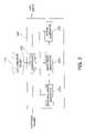
- FIG. 1is a block diagram of an imaging device according to an embodiment of the present invention.
- FIG. 2is a block diagram of an image processor included in the imaging device shown in FIG. 1 , according to an embodiment of the present invention
- FIG. 3is a flow chart illustrating a method for constructing an HDR image, according to the present invention
- FIG. 4Ais an example illustrating capture of multiple images of a scene using a range of exposure times
- FIG. 4Bis an example illustrating capture of a single image of the scene shown in FIG. 4A including an object placed in the scene;
- FIG. 5is an example illustrating generation of a masked image based on the multiple scene images shown in FIG. 4A and the single object image shown in FIG. 4B ;
- FIG. 6is an example illustrating formation of an HDR image from the multiple scene images shown in FIG. 4A and the single object image shown in FIG. 4B using the masked image shown in FIG. 5 ;
- FIG. 7is a block diagram of a processing system incorporating an image processor according to an embodiment of the present invention.
- FIG. 8is a conventional graph of scene exposure as a function of camera sensor pixel value illustrating examples of HDR weighting functions used to form a radiance image from multiple scene images.
- aspects of the present inventionrelate to the capture of high dynamic range (HDR) images with objects, such as people, included in a scene.
- An HDR image that includes objectsis generated by using a low dynamic range exposure of the object in the scene, as well as a high dynamic range exposure of the scene itself (i.e. without the object). Because an image of people generally tends to have a limited dynamic range, a single exposure at a suitable exposure setting may be used to cover the entire dynamic range for the people in the scene.
- FIG. 1is a block diagram of an imaging device, designated generally as 100 , used to capture digital images and generate HDR images.
- Imaging device 100includes shutter 102 , imaging optics 104 , image sensor 106 , image processor 108 , display 110 , user interface 112 and memory 114 .
- imaging device 100is a hand-held digital camera used to capture still digital images.
- imaging device 100is a digital video camera used to capture digital video.
- Shutter 102 , imaging optics 104 and imager sensor 106are conventional devices that are well known in digital imaging devices. Display 110 and memory 114 are also well known in digital imaging devices. Image sensor 106 may include CCD and CMOS devices. Image sensor 106 includes an array of optical detectors, referred to as pixels, which individually detect light and generate electrical responses in proportion to received light. In order to capture color images, image sensor 106 also includes color filters, for example, a color filter array (CFA) that separates incident light into different colors, such as red, blue and green and passes the filtered light to the pixels.
- shutter 102 , imaging optics 104 , display 110 , user interface 112 and memory 114are integrated with image sensor 106 and image processing unit 108 into a digital camera.
- Image data generated from image sensor 106is provided to image processor 108 as captured images and stored in memory 114 .
- Image processor 108uses the captured images to generate an HDR image that may be displayed on display 110 and/or provided to memory 114 .
- image processor 108uses the captured images of a scene over a range of exposure settings and another image of an object in the scene to generate the HDR image, described further below with respect to FIG. 2 .
- An HDR imageis typically captured using multiple exposures so that both the low and high scene luminance components may be captured with sufficient accuracy.
- HDR image constructiontypically takes longer to process than the time it takes to generate an image from a single exposure. For substantially stationary objects, such as a house, a longer period for capturing multiple images is not a concern. For scenes containing objects such as people and/or animals, however, a long capture period and longer exposure times may create problems with motion artifacts.
- Image registrationrefers to a process of providing point by point correspondence among multiple images in a scene.
- An example of image registrationis provided in U.S. Pat. No. 7,142,723 issued to Kang et al.
- the image registration processmay create artifacts (e.g., edge blurs or ghost images) in the resulting HDR image in regions where objects move between various exposures.
- imaging device 100is typically placed on a tripod (not shown), to minimize effects of any motion artifacts during image capture.
- the scenemay be considered substantially constant over time.
- image processor 108may generate an HDR image from multiple captured images of a scene over a range of exposure times, without requiring to detect motion, apply motion compensation processing or perform image registration.
- the exposure for each imagemay be controlled by varying shutter speed, F-number (i.e. the brightness of the image), or exposure time of image sensor 106 .
- the “dynamic range” of an imagerefers to the range from the lowest pixel brightness value in the image (corresponding to the lowest detected intensity) to the highest pixel brightness value in the image (corresponding to the highest detected intensity).
- an objectsuch as a person
- a relatively stationary personmay be captured in an image with a short exposure time of about 1/30 of a second without detecting movement. When the exposure time becomes about 1 second, for example, even though the person is relatively stationary, there may still be movement in the captured image that degrades the HDR image quality.
- the entire HDR capture processmay take about 1 to 2 minutes, including all the exposures and preparation time. Accordingly, if a person (relatively stationary) is included in a scene (substantially constant) and an HDR image is generated from multiple images over a range of exposure times, the quality of the image may be degraded due to motion artifacts. As a result of such HDR capture process with people in the scene, direct merging of individual images in the HDR sequence may cause edges of the moving elements to blur and degrade the quality of the HDR image.
- imaging device 100captures multiple images of the scene (referred to herein as multiple scene images) over a range of exposure times T 1 , T 2 , . . . , T N (i.e., over a high dynamic range).
- the range of exposure timesmay include T 1 of about 1/8000 of a second to T N of about 20 seconds for 14 different exposure times at a fixed aperture value.
- an objectmay be placed in the scene and then imaging device 100 may capture another image of that object (referred to herein as an object image) at a single low exposure time suitable for capturing the object.
- the single object imagemay be captured with a low dynamic range.
- Image processor 108forms an HDR image using the multiple scene images that do not include the object and merges the other image that includes the object.
- the process of the inventionuses images with substantially no motion. Accordingly, motion artifacts are reduced.
- User interface 112may be used to selectively capture the multiple scene images or the object image.
- image processor 108may be directed to adjust one or more of the speed of shutter 102 , the focus of imaging optics 104 , or the exposure time of image sensor 106 .
- image processor 108is illustrated as controlling adjustment of shutter 102 , imaging optics 104 and image sensor 106 , it will be understood that imaging device 100 may be configured by other means to adjust shutter speed, focus, F-number, exposure time and/or any other parameter in order to capture images with different exposure settings and provide both high and low dynamic range images.
- a predetermined range of exposure settingsmay be used to capture the multiple scene images.
- the range of exposure settingsmay be stored in memory 114 .
- imaging device 100may determine a suitable exposure setting or exposure time T i for the object, depending upon lighting conditions, distance to the object, focusing of the object, etc.
- imaging device 100may capture a test image and adjust the exposure settings to optimize capture of the single object image.
- the exposure settings for the object imagemay be adjusted, for example, based on a lookup table stored in memory 114 . It will be understood that exposure time Ti of the object image may be different from exposure times of the multiple captured scene images.
- a range of illumination for the multiple scene imagesmay be greater than 100 dB (decibels) whereas a range of illumination for the single object image may be less than about 30 dB.
- FIG. 2is a block diagram of image processor 108 .
- Image processor 108includes controller 202 , radiance image generator 204 , mask image generator 206 and merge generator 208 . Captured images may be provided to controller 202 and stored in memory 114 . An HDR image generated by image processor 108 may be provided from controller 202 to memory 114 and/or display 110 ( FIG. 1 ). Image processor 108 may include any suitable software for generating HDR images.
- Controller 202controls radiance image generator 204 , mask image generator 206 and merge generator 208 for generating an HDR image from multiple captured scene images (over a range of exposure settings) and another object image (at a low exposure setting). Controller 202 may also receive selection information from user interface 112 and adjust one or more settings of shutter 102 , imaging optics 104 or image sensor 106 , according to whether multiple scene images or a single object image is selected.
- Radiance image generator 204receives multiple images of the scene (having a high dynamic range) and form a first radiance image from the multiple images. Radiance image generator 204 also receives the other image of the object in the scene (having a low dynamic range) and form a second radiance image.
- An example of radiance image generationis described in U.S. Pat. No. 7,142,723 issued to Kang et al.
- input imagesare converted to a radiance image using a known exposure value and a known imaging device response function F response .
- a final radiance value at a pixelis typically computed as a weighted sum of the corresponding pixels in the radiance images.
- the radiance of an individual pixelis typically provided as:
- the imaging device response functionmay include known imaging device parameters used to capture the multiple scene images or the object image. For example, the speed of shutter 102 and aperture settings of imaging optics 104 . In one embodiment, suitable imaging device parameters are stored, for example, as metadata information associated with each of the images.
- the camera system response curveis known and is inverted to form inverted camera system response curve 806 (shown in FIG. 8 as a function of scene exposure 804 and camera sensor pixel value 802 ). The inverted camera response curve 806 is used to revert to a linear relationship between scene radiances and pixel values.
- a first radiance imageis generated from the multiple scene images, by combining the pixel radiances from the multiple scene images, and a second radiance image is generated from the single object image.
- a weighting functionis typically used to average the linear exposures together.
- FIG. 8two examples of weighting functions 808 , 810 are shown with respect to scene exposure 804 and camera sensor pixel values 802 . Because low-value pixels tend to be prone to noise and high-value pixels tend to be prone to pixel saturation, weighting functions 808 , 810 are based on the assumption that mid-range pixels tend to be more reliable for radiance estimation than low- and high-value pixels.
- Mask image generator 206receives at least one of the multiple scene images and the object image and subsequently generate a masked image. In one embodiment, controller 202 selects one of the multiple scene images having similar exposure times as the exposure time of the object image. In another embodiment, mask image generator 206 receives multiple scene images and selects one of the multiple scene images as the exposure time. In one embodiment, the selected scene image and the object image are subtracted from each other to form a differential image. The difference between the selected scene image and the object image emphasizes the object in the scene, because features that are common to both images (i.e. the remainder of the scene) are substantially minimized.
- a boundaryis formed around the object in the differential image.
- the regions that include the objectmay be given minimum pixel values (e.g. 0), whereas regions that do not include the object may be given maximum pixels values (e.g. 1).
- a second (i.e. inverse) masked imageis generated from the inverse of the masked image.
- the boundary between the regions excluding/including the objectmay have a sharp (i.e. binary) transition (e.g. 0 to 1) or a soft transition (e.g. a slope from 0 to 1).
- a soft transitionmay result in the merged object in the HDR image appearing more natural to response of the human eye.
- mask image generator 206receives the first and second radiance images generated by radiance image generator 204 and, using the masked image and inverse masked image, forms respective first and second masked radiance images.
- merge generator 208forms the first and second masked radiance images, using the masked image and inverse masked image generated by mask image generator 206 .
- controller 202may form the first and second masked radiance images, using the masked image and inverse masked image, and subsequently provide the masked first and second radiance images to merge generator 208 .
- the first masked radiance imageis formed by multiplying the inverse masked image and the first radiance image. In this manner, the scene, without the object, is included in the masked first radiance image.
- the second masked radiance imageis formed by multiplying the masked image and the second radiance image. Accordingly, the object, without the scene, is included in the second masked radiance image.
- Merge generator 208receives the first and second radiance images, the masked image and inverse masked image (or the masked first and second radiance images) and generate a merged HDR image.
- the masked first and second radiance imagesmay be summed together.
- the summation at the borders of the two regionsis processed differently from the rest of the image.
- a gradient weighting functionis applied so that a smooth transition is achieved between the two regions. Additional adjustments in white balance, exposure, or tonal mapping may be applied to either or both of the two regions to achieve the most pleasing results of the final HDR image.
- FIG. 3is a flow chart illustrating a method for constructing an HDR image.
- FIG. 4Ais an example illustrating the capture of multiple scene images 402 using a range of exposure times T 1 , . . . T N .
- FIG. 4Bis an example illustrating the capture of object image 404 , shown in FIG. 4A , at a low exposure time T i with object 406 placed in the scene.
- FIG. 5is an example illustrating the generation of a masked image 506 based on one of the multiple scene images 402 , shown in FIG. 4A , and object image 404 shown in FIG. 4B .
- FIG. 6is an example illustrating formation of HDR image 606 from the multiple scene images, shown in FIG. 4A , and the object image, shown in FIG. 4B , using masked image 506 , shown in FIG. 5 .
- FIG. 3represent an embodiment of the present invention. It will be understood that certain steps may be performed in a sequence different from the sequence shown. Some of the steps may be performed simultaneously with other steps.
- multiple scene imagesare captured and stored in memory 114 ( FIG. 1 ).
- multiple scene images 402 at exposure times T 1 , . . . , T Nare captured.
- an objecte.g. a person
- this object imageis captured in the scene.
- the object imagemay also be stored in memory 114 ( FIG. 1 ).
- object 406is placed in the scene and object image 404 is captured with exposure time T i .
- At step 306at least one multiple scene image is compared to the object image to generate a masked image.
- one of the multiple scene imagesmay be selected based on similar exposure settings (e.g. ⁇ T i ) to the exposure setting (e.g. T i ) of the object image.
- the selected scene image and the object imagemay then be subtracted from each other to form a masked image.
- scene image 402 (T i ) and object image 404are subtracted by subtractor 502 to form differential image 504 .
- a masked image 506is formed based on the border of object 406 in differential image 504 .
- an inverse masked imagemay be generated, as described above, from masked image 506 .
- a first radiance imageis generated from the multiple scene images, for example, by radiance image generator 204 ( FIG. 2 ).
- a second radiance imageis generated from the object image, for example, by radiance image generator 204 ( FIG. 2 ).
- the first radiance imageis masked by an inverse masked image, for example, by mask image generator 206 ( FIG. 2 ).
- the second radiance imageis masked by the masked image.
- the first and second masked radiance imagesare merged to form the HDR image, for example, by merge generator 208 ( FIG. 2 ). Accordingly, regions of the scene that do not include the object may be represented by the multiple scene images captured over a high dynamic range, whereas region(s) of the scene that includes the object (object image) may be captured with a low dynamic range.
- a first masked radiance image 602is formed by masking the first radiance image with an inverse masked image.
- a second masked radiance image 602is formed by masking the second radiance image with masked image 506 ( FIG. 5 ).
- the resulting HDR image 606is a merging of the first masked radiance image 602 with the second masked radiance image 604 . Accordingly, regions of the first radiance image including object 406 are excluded from the first masked radiance image 602 and regions of the second radiance image that do not include object 406 are excluded from the second masked radiance image 604 .
- FIG. 7shows a typical processor-based system, designated generally as 700 , which includes imaging device 100 .
- the processor-based system 700includes central processing unit (CPU) 702 which communicates over bus 710 with input/output (I/O) device 706 and imaging device 100 .
- the processor-based system 700also includes random access memory (RAM) 704 , and removable memory 708 , such as a flash memory. At least a part of CPU 702 , RAM 704 , and imaging device 100 may be integrated on the same circuit chip.
Landscapes
- Engineering & Computer Science (AREA)
- Multimedia (AREA)
- Signal Processing (AREA)
- Physics & Mathematics (AREA)
- General Physics & Mathematics (AREA)
- Theoretical Computer Science (AREA)
- Studio Devices (AREA)
- Image Processing (AREA)
Abstract
Description
where Rad is the radiance of a pixel, p is the pixel intensity and exp is an exposure level. The imaging device response function may include known imaging device parameters used to capture the multiple scene images or the object image. For example, the speed of
Claims (40)
Priority Applications (1)
| Application Number | Priority Date | Filing Date | Title |
|---|---|---|---|
| US12/115,022US8724921B2 (en) | 2008-05-05 | 2008-05-05 | Method of capturing high dynamic range images with objects in the scene |
Applications Claiming Priority (1)
| Application Number | Priority Date | Filing Date | Title |
|---|---|---|---|
| US12/115,022US8724921B2 (en) | 2008-05-05 | 2008-05-05 | Method of capturing high dynamic range images with objects in the scene |
Publications (2)
| Publication Number | Publication Date |
|---|---|
| US20090274387A1 US20090274387A1 (en) | 2009-11-05 |
| US8724921B2true US8724921B2 (en) | 2014-05-13 |
Family
ID=41257128
Family Applications (1)
| Application Number | Title | Priority Date | Filing Date |
|---|---|---|---|
| US12/115,022Active2033-03-13US8724921B2 (en) | 2008-05-05 | 2008-05-05 | Method of capturing high dynamic range images with objects in the scene |
Country Status (1)
| Country | Link |
|---|---|
| US (1) | US8724921B2 (en) |
Cited By (5)
| Publication number | Priority date | Publication date | Assignee | Title |
|---|---|---|---|---|
| US20150228098A1 (en)* | 2014-02-10 | 2015-08-13 | International Business Machines Corporation | Simplified lighting compositing |
| US20160292837A1 (en)* | 2015-03-30 | 2016-10-06 | Imagination Technologies Limited | Image filtering based on image gradients |
| WO2016165967A1 (en) | 2015-04-14 | 2016-10-20 | Fotonation Limited | Image acquisition method and apparatus |
| US9874630B2 (en) | 2015-01-30 | 2018-01-23 | Microsoft Technology Licensing, Llc | Extended range gated time of flight camera |
| US11653101B2 (en) | 2019-05-17 | 2023-05-16 | Samsung Electronics Co., Ltd. | Imaging system for generating high dynamic range image |
Families Citing this family (90)
| Publication number | Priority date | Publication date | Assignee | Title |
|---|---|---|---|---|
| US8866920B2 (en) | 2008-05-20 | 2014-10-21 | Pelican Imaging Corporation | Capturing and processing of images using monolithic camera array with heterogeneous imagers |
| DK3876510T3 (en) | 2008-05-20 | 2024-11-11 | Adeia Imaging Llc | CAPTURE AND PROCESSING OF IMAGES USING MONOLITHIC CAMERA ARRAY WITH HETEROGENEOUS IMAGES |
| US11792538B2 (en) | 2008-05-20 | 2023-10-17 | Adeia Imaging Llc | Capturing and processing of images including occlusions focused on an image sensor by a lens stack array |
| US8587681B2 (en)* | 2008-11-21 | 2013-11-19 | Omnivision Technologies, Inc. | Extended depth of field for image sensor |
| US20100157079A1 (en)* | 2008-12-19 | 2010-06-24 | Qualcomm Incorporated | System and method to selectively combine images |
| KR101604068B1 (en)* | 2009-09-22 | 2016-03-17 | 삼성전자주식회사 | High dynamic range imaging apparatus and method |
| EP2502115A4 (en) | 2009-11-20 | 2013-11-06 | Pelican Imaging Corp | CAPTURE AND IMAGE PROCESSING USING A MONOLITHIC CAMERAS NETWORK EQUIPPED WITH HETEROGENEOUS IMAGERS |
| US20120288217A1 (en)* | 2010-01-27 | 2012-11-15 | Jiefu Zhai | High dynamic range (hdr) image synthesis with user input |
| US8928793B2 (en) | 2010-05-12 | 2015-01-06 | Pelican Imaging Corporation | Imager array interfaces |
| US8760537B2 (en) | 2010-07-05 | 2014-06-24 | Apple Inc. | Capturing and rendering high dynamic range images |
| US8878950B2 (en) | 2010-12-14 | 2014-11-04 | Pelican Imaging Corporation | Systems and methods for synthesizing high resolution images using super-resolution processes |
| US9024951B2 (en) | 2011-02-16 | 2015-05-05 | Apple Inc. | Devices and methods for obtaining high-local-contrast image data |
| EP2708019B1 (en) | 2011-05-11 | 2019-10-16 | FotoNation Limited | Systems and methods for transmitting and receiving array camera image data |
| US20130265459A1 (en) | 2011-06-28 | 2013-10-10 | Pelican Imaging Corporation | Optical arrangements for use with an array camera |
| KR101843450B1 (en)* | 2011-08-23 | 2018-03-29 | 엘지전자 주식회사 | Mobile terminal and method for controlling of the same |
| US20130070060A1 (en) | 2011-09-19 | 2013-03-21 | Pelican Imaging Corporation | Systems and methods for determining depth from multiple views of a scene that include aliasing using hypothesized fusion |
| CN104081414B (en) | 2011-09-28 | 2017-08-01 | Fotonation开曼有限公司 | Systems and methods for encoding and decoding light field image files |
| JP5713885B2 (en)* | 2011-12-26 | 2015-05-07 | キヤノン株式会社 | Image processing apparatus, image processing method, program, and storage medium |
| EP2817955B1 (en) | 2012-02-21 | 2018-04-11 | FotoNation Cayman Limited | Systems and methods for the manipulation of captured light field image data |
| US9210392B2 (en) | 2012-05-01 | 2015-12-08 | Pelican Imaging Coporation | Camera modules patterned with pi filter groups |
| JP2015534734A (en) | 2012-06-28 | 2015-12-03 | ペリカン イメージング コーポレイション | System and method for detecting defective camera arrays, optical arrays, and sensors |
| US20140002674A1 (en) | 2012-06-30 | 2014-01-02 | Pelican Imaging Corporation | Systems and Methods for Manufacturing Camera Modules Using Active Alignment of Lens Stack Arrays and Sensors |
| PL4296963T3 (en) | 2012-08-21 | 2025-04-28 | Adeia Imaging Llc | Method for depth detection in images captured using array cameras |
| WO2014032020A2 (en) | 2012-08-23 | 2014-02-27 | Pelican Imaging Corporation | Feature based high resolution motion estimation from low resolution images captured using an array source |
| US8446481B1 (en)* | 2012-09-11 | 2013-05-21 | Google Inc. | Interleaved capture for high dynamic range image acquisition and synthesis |
| US9214013B2 (en) | 2012-09-14 | 2015-12-15 | Pelican Imaging Corporation | Systems and methods for correcting user identified artifacts in light field images |
| US9525825B1 (en)* | 2012-09-25 | 2016-12-20 | Amazon Technologies, Inc. | Delayed image data processing |
| EP4307659A1 (en) | 2012-09-28 | 2024-01-17 | Adeia Imaging LLC | Generating images from light fields utilizing virtual viewpoints |
| WO2014078443A1 (en) | 2012-11-13 | 2014-05-22 | Pelican Imaging Corporation | Systems and methods for array camera focal plane control |
| US8866927B2 (en) | 2012-12-13 | 2014-10-21 | Google Inc. | Determining an image capture payload burst structure based on a metering image capture sweep |
| US9087391B2 (en) | 2012-12-13 | 2015-07-21 | Google Inc. | Determining an image capture payload burst structure |
| US8866928B2 (en) | 2012-12-18 | 2014-10-21 | Google Inc. | Determining exposure times using split paxels |
| US9247152B2 (en) | 2012-12-20 | 2016-01-26 | Google Inc. | Determining image alignment failure |
| US8995784B2 (en) | 2013-01-17 | 2015-03-31 | Google Inc. | Structure descriptors for image processing |
| US9686537B2 (en) | 2013-02-05 | 2017-06-20 | Google Inc. | Noise models for image processing |
| US9462164B2 (en) | 2013-02-21 | 2016-10-04 | Pelican Imaging Corporation | Systems and methods for generating compressed light field representation data using captured light fields, array geometry, and parallax information |
| US9374512B2 (en) | 2013-02-24 | 2016-06-21 | Pelican Imaging Corporation | Thin form factor computational array cameras and modular array cameras |
| US9774789B2 (en) | 2013-03-08 | 2017-09-26 | Fotonation Cayman Limited | Systems and methods for high dynamic range imaging using array cameras |
| US8866912B2 (en) | 2013-03-10 | 2014-10-21 | Pelican Imaging Corporation | System and methods for calibration of an array camera using a single captured image |
| US9521416B1 (en) | 2013-03-11 | 2016-12-13 | Kip Peli P1 Lp | Systems and methods for image data compression |
| WO2014165244A1 (en) | 2013-03-13 | 2014-10-09 | Pelican Imaging Corporation | Systems and methods for synthesizing images from image data captured by an array camera using restricted depth of field depth maps in which depth estimation precision varies |
| US9106784B2 (en) | 2013-03-13 | 2015-08-11 | Pelican Imaging Corporation | Systems and methods for controlling aliasing in images captured by an array camera for use in super-resolution processing |
| US9888194B2 (en) | 2013-03-13 | 2018-02-06 | Fotonation Cayman Limited | Array camera architecture implementing quantum film image sensors |
| US9124831B2 (en) | 2013-03-13 | 2015-09-01 | Pelican Imaging Corporation | System and methods for calibration of an array camera |
| WO2014153098A1 (en) | 2013-03-14 | 2014-09-25 | Pelican Imaging Corporation | Photmetric normalization in array cameras |
| US9578259B2 (en) | 2013-03-14 | 2017-02-21 | Fotonation Cayman Limited | Systems and methods for reducing motion blur in images or video in ultra low light with array cameras |
| US9445003B1 (en) | 2013-03-15 | 2016-09-13 | Pelican Imaging Corporation | Systems and methods for synthesizing high resolution images using image deconvolution based on motion and depth information |
| US9438888B2 (en) | 2013-03-15 | 2016-09-06 | Pelican Imaging Corporation | Systems and methods for stereo imaging with camera arrays |
| US9633442B2 (en) | 2013-03-15 | 2017-04-25 | Fotonation Cayman Limited | Array cameras including an array camera module augmented with a separate camera |
| US9497429B2 (en) | 2013-03-15 | 2016-11-15 | Pelican Imaging Corporation | Extended color processing on pelican array cameras |
| US10122993B2 (en) | 2013-03-15 | 2018-11-06 | Fotonation Limited | Autofocus system for a conventional camera that uses depth information from an array camera |
| WO2014150856A1 (en) | 2013-03-15 | 2014-09-25 | Pelican Imaging Corporation | Array camera implementing quantum dot color filters |
| US9117134B1 (en) | 2013-03-19 | 2015-08-25 | Google Inc. | Image merging with blending |
| US9066017B2 (en) | 2013-03-25 | 2015-06-23 | Google Inc. | Viewfinder display based on metering images |
| US10382674B2 (en)* | 2013-04-15 | 2019-08-13 | Qualcomm Incorporated | Reference image selection for motion ghost filtering |
| US9077913B2 (en) | 2013-05-24 | 2015-07-07 | Google Inc. | Simulating high dynamic range imaging with virtual long-exposure images |
| US9131201B1 (en) | 2013-05-24 | 2015-09-08 | Google Inc. | Color correcting virtual long exposures with true long exposures |
| US9898856B2 (en) | 2013-09-27 | 2018-02-20 | Fotonation Cayman Limited | Systems and methods for depth-assisted perspective distortion correction |
| US9615012B2 (en) | 2013-09-30 | 2017-04-04 | Google Inc. | Using a second camera to adjust settings of first camera |
| US9264592B2 (en) | 2013-11-07 | 2016-02-16 | Pelican Imaging Corporation | Array camera modules incorporating independently aligned lens stacks |
| US10119808B2 (en) | 2013-11-18 | 2018-11-06 | Fotonation Limited | Systems and methods for estimating depth from projected texture using camera arrays |
| WO2015081279A1 (en) | 2013-11-26 | 2015-06-04 | Pelican Imaging Corporation | Array camera configurations incorporating multiple constituent array cameras |
| US10089740B2 (en) | 2014-03-07 | 2018-10-02 | Fotonation Limited | System and methods for depth regularization and semiautomatic interactive matting using RGB-D images |
| KR102160120B1 (en) | 2014-03-14 | 2020-09-25 | 삼성전자주식회사 | Sampling period control circuit capable of controlling sampling period |
| US9247117B2 (en) | 2014-04-07 | 2016-01-26 | Pelican Imaging Corporation | Systems and methods for correcting for warpage of a sensor array in an array camera module by introducing warpage into a focal plane of a lens stack array |
| US9521319B2 (en) | 2014-06-18 | 2016-12-13 | Pelican Imaging Corporation | Array cameras and array camera modules including spectral filters disposed outside of a constituent image sensor |
| JP2017531976A (en) | 2014-09-29 | 2017-10-26 | フォトネイション ケイマン リミテッド | System and method for dynamically calibrating an array camera |
| US9942474B2 (en) | 2015-04-17 | 2018-04-10 | Fotonation Cayman Limited | Systems and methods for performing high speed video capture and depth estimation using array cameras |
| WO2019031086A1 (en)* | 2017-08-09 | 2019-02-14 | 富士フイルム株式会社 | Image processing system, server device, image processing method, and image processing program |
| US10482618B2 (en) | 2017-08-21 | 2019-11-19 | Fotonation Limited | Systems and methods for hybrid depth regularization |
| CN108288253B (en)* | 2018-01-08 | 2020-11-27 | 厦门美图之家科技有限公司 | HDR image generation method and device |
| US11270110B2 (en) | 2019-09-17 | 2022-03-08 | Boston Polarimetrics, Inc. | Systems and methods for surface modeling using polarization cues |
| WO2021071992A1 (en) | 2019-10-07 | 2021-04-15 | Boston Polarimetrics, Inc. | Systems and methods for augmentation of sensor systems and imaging systems with polarization |
| DE112020005932T5 (en) | 2019-11-30 | 2023-01-05 | Boston Polarimetrics, Inc. | SYSTEMS AND METHODS FOR SEGMENTATION OF TRANSPARENT OBJECTS USING POLARIZATION CHARACTERISTICS |
| EP4081933A4 (en) | 2020-01-29 | 2024-03-20 | Intrinsic Innovation LLC | Systems and methods for characterizing object pose detection and measurement systems |
| US11797863B2 (en) | 2020-01-30 | 2023-10-24 | Intrinsic Innovation Llc | Systems and methods for synthesizing data for training statistical models on different imaging modalities including polarized images |
| US11953700B2 (en) | 2020-05-27 | 2024-04-09 | Intrinsic Innovation Llc | Multi-aperture polarization optical systems using beam splitters |
| WO2022103426A1 (en)* | 2020-11-12 | 2022-05-19 | Innopeak Technology, Inc. | Image fusion in radiance domain |
| US11978181B1 (en) | 2020-12-11 | 2024-05-07 | Nvidia Corporation | Training a neural network using luminance |
| US11637998B1 (en)* | 2020-12-11 | 2023-04-25 | Nvidia Corporation | Determination of luminance values using image signal processing pipeline |
| US12069227B2 (en) | 2021-03-10 | 2024-08-20 | Intrinsic Innovation Llc | Multi-modal and multi-spectral stereo camera arrays |
| US12020455B2 (en) | 2021-03-10 | 2024-06-25 | Intrinsic Innovation Llc | Systems and methods for high dynamic range image reconstruction |
| US11290658B1 (en) | 2021-04-15 | 2022-03-29 | Boston Polarimetrics, Inc. | Systems and methods for camera exposure control |
| US11954886B2 (en) | 2021-04-15 | 2024-04-09 | Intrinsic Innovation Llc | Systems and methods for six-degree of freedom pose estimation of deformable objects |
| US12067746B2 (en) | 2021-05-07 | 2024-08-20 | Intrinsic Innovation Llc | Systems and methods for using computer vision to pick up small objects |
| US12175741B2 (en) | 2021-06-22 | 2024-12-24 | Intrinsic Innovation Llc | Systems and methods for a vision guided end effector |
| US12340538B2 (en) | 2021-06-25 | 2025-06-24 | Intrinsic Innovation Llc | Systems and methods for generating and using visual datasets for training computer vision models |
| US12172310B2 (en) | 2021-06-29 | 2024-12-24 | Intrinsic Innovation Llc | Systems and methods for picking objects using 3-D geometry and segmentation |
| US11689813B2 (en) | 2021-07-01 | 2023-06-27 | Intrinsic Innovation Llc | Systems and methods for high dynamic range imaging using crossed polarizers |
| US12293535B2 (en) | 2021-08-03 | 2025-05-06 | Intrinsic Innovation Llc | Systems and methods for training pose estimators in computer vision |
Citations (34)
| Publication number | Priority date | Publication date | Assignee | Title |
|---|---|---|---|---|
| US5144442A (en) | 1988-02-08 | 1992-09-01 | I Sight, Inc. | Wide dynamic range camera |
| US5309243A (en) | 1992-06-10 | 1994-05-03 | Eastman Kodak Company | Method and apparatus for extending the dynamic range of an electronic imaging system |
| US5828793A (en)* | 1996-05-06 | 1998-10-27 | Massachusetts Institute Of Technology | Method and apparatus for producing digital images having extended dynamic ranges |
| US5914748A (en)* | 1996-08-30 | 1999-06-22 | Eastman Kodak Company | Method and apparatus for generating a composite image using the difference of two images |
| KR20010036040A (en) | 1999-10-05 | 2001-05-07 | 윤종용 | Apparatus and method for expanding dynamic range of image process system |
| US20020154829A1 (en)* | 2001-03-12 | 2002-10-24 | Taketo Tsukioka | Image pickup apparatus |
| US20030095192A1 (en)* | 2000-10-26 | 2003-05-22 | Olympus Optical Co., Ltd. | Image-pickup apparatus |
| US20030151689A1 (en) | 2002-02-11 | 2003-08-14 | Murphy Charles Douglas | Digital images with composite exposure |
| US20040100565A1 (en) | 2002-11-22 | 2004-05-27 | Eastman Kodak Company | Method and system for generating images used in extended range panorama composition |
| JP2005175870A (en) | 2003-12-11 | 2005-06-30 | Sony Corp | Motion vector detecting apparatus, motion vector detecting method and computer program |
| US20050275747A1 (en) | 2002-03-27 | 2005-12-15 | Nayar Shree K | Imaging method and system |
| US20060002611A1 (en) | 2004-07-02 | 2006-01-05 | Rafal Mantiuk | Method and apparatus for encoding high dynamic range video |
| US20060017837A1 (en) | 2004-07-22 | 2006-01-26 | Sightic Vista Ltd. | Enhancing digital photography |
| US20060083440A1 (en) | 2004-10-20 | 2006-04-20 | Hewlett-Packard Development Company, L.P. | System and method |
| US20060114333A1 (en) | 2004-02-12 | 2006-06-01 | Canesta, Inc. | Method and system to increase dynamic range of time-of-flight (TOF) and/or imaging sensors |
| US7057650B1 (en)* | 1998-06-22 | 2006-06-06 | Fuji Photo Film Co., Ltd. | Image sensing apparatus and method for synthesizing a composite image |
| US7061524B2 (en) | 2001-11-13 | 2006-06-13 | The Board Of Trustees Of The Leland Stanford Junior University | Motion/saturation detection system and method for synthesizing high dynamic range motion blur free images from multiple captures |
| WO2006073875A2 (en) | 2005-01-06 | 2006-07-13 | Recon/Optical, Inc. | Cmos active pixel sensor with improved dynamic range and method of operation, method for identifying moving objects and hybrid array with ir detector |
| US20060192867A1 (en) | 2005-02-01 | 2006-08-31 | Transchip, Inc | Variable exposure for color image sensor |
| US20060192873A1 (en) | 2005-02-01 | 2006-08-31 | Transchip, Inc. | Dual exposure for image sensor |
| US20060209204A1 (en) | 2005-03-21 | 2006-09-21 | Sunnybrook Technologies Inc. | Multiple exposure methods and apparatus for electronic cameras |
| US7127084B1 (en)* | 2002-03-22 | 2006-10-24 | Mauk Jamey R | Method of creating digital composite files of superimposed images |
| US20060251216A1 (en) | 2005-05-03 | 2006-11-09 | General Electric Company | Methods and systems for controlling exposure for medical imaging devices |
| US7142723B2 (en) | 2003-07-18 | 2006-11-28 | Microsoft Corporation | System and process for generating high dynamic range images from multiple exposures of a moving scene |
| US20070002164A1 (en) | 2005-03-21 | 2007-01-04 | Brightside Technologies Inc. | Multiple exposure methods and apparatus for electronic cameras |
| US7239805B2 (en) | 2005-02-01 | 2007-07-03 | Microsoft Corporation | Method and system for combining multiple exposure images having scene and camera motion |
| JP2007221423A (en) | 2006-02-16 | 2007-08-30 | Matsushita Electric Ind Co Ltd | Imaging device |
| US20070242900A1 (en) | 2006-04-13 | 2007-10-18 | Mei Chen | Combining multiple exposure images to increase dynamic range |
| US20070257184A1 (en) | 2005-08-25 | 2007-11-08 | Olsen Richard I | Large dynamic range cameras |
| US7301563B1 (en) | 1998-07-28 | 2007-11-27 | Olympus Optical Co., Ltd. | Image pickup apparatus |
| US20080023623A1 (en) | 2005-09-21 | 2008-01-31 | Sorin Davidovici | System and Method for A High Dynamic Range Sensitive Sensor Element Array |
| US7443533B2 (en)* | 2004-09-17 | 2008-10-28 | Corel Tw Corp. | Image composition systems and methods |
| US7519907B2 (en)* | 2003-08-04 | 2009-04-14 | Microsoft Corp. | System and method for image editing using an image stack |
| US7612804B1 (en)* | 2005-02-15 | 2009-11-03 | Apple Inc. | Methods and apparatuses for image processing |
- 2008
- 2008-05-05USUS12/115,022patent/US8724921B2/enactiveActive
Patent Citations (36)
| Publication number | Priority date | Publication date | Assignee | Title |
|---|---|---|---|---|
| US5144442A (en) | 1988-02-08 | 1992-09-01 | I Sight, Inc. | Wide dynamic range camera |
| US5309243A (en) | 1992-06-10 | 1994-05-03 | Eastman Kodak Company | Method and apparatus for extending the dynamic range of an electronic imaging system |
| US5828793A (en)* | 1996-05-06 | 1998-10-27 | Massachusetts Institute Of Technology | Method and apparatus for producing digital images having extended dynamic ranges |
| US5914748A (en)* | 1996-08-30 | 1999-06-22 | Eastman Kodak Company | Method and apparatus for generating a composite image using the difference of two images |
| US7057650B1 (en)* | 1998-06-22 | 2006-06-06 | Fuji Photo Film Co., Ltd. | Image sensing apparatus and method for synthesizing a composite image |
| US7301563B1 (en) | 1998-07-28 | 2007-11-27 | Olympus Optical Co., Ltd. | Image pickup apparatus |
| KR20010036040A (en) | 1999-10-05 | 2001-05-07 | 윤종용 | Apparatus and method for expanding dynamic range of image process system |
| US20030095192A1 (en)* | 2000-10-26 | 2003-05-22 | Olympus Optical Co., Ltd. | Image-pickup apparatus |
| US7349119B2 (en)* | 2001-03-12 | 2008-03-25 | Olympus Corporation | Image storage and control device for camera to generate synthesized image with wide dynamic range |
| US20020154829A1 (en)* | 2001-03-12 | 2002-10-24 | Taketo Tsukioka | Image pickup apparatus |
| US7061524B2 (en) | 2001-11-13 | 2006-06-13 | The Board Of Trustees Of The Leland Stanford Junior University | Motion/saturation detection system and method for synthesizing high dynamic range motion blur free images from multiple captures |
| US20030151689A1 (en) | 2002-02-11 | 2003-08-14 | Murphy Charles Douglas | Digital images with composite exposure |
| US7127084B1 (en)* | 2002-03-22 | 2006-10-24 | Mauk Jamey R | Method of creating digital composite files of superimposed images |
| US7495699B2 (en)* | 2002-03-27 | 2009-02-24 | The Trustees Of Columbia University In The City Of New York | Imaging method and system |
| US20050275747A1 (en) | 2002-03-27 | 2005-12-15 | Nayar Shree K | Imaging method and system |
| US20040100565A1 (en) | 2002-11-22 | 2004-05-27 | Eastman Kodak Company | Method and system for generating images used in extended range panorama composition |
| US7142723B2 (en) | 2003-07-18 | 2006-11-28 | Microsoft Corporation | System and process for generating high dynamic range images from multiple exposures of a moving scene |
| US7519907B2 (en)* | 2003-08-04 | 2009-04-14 | Microsoft Corp. | System and method for image editing using an image stack |
| JP2005175870A (en) | 2003-12-11 | 2005-06-30 | Sony Corp | Motion vector detecting apparatus, motion vector detecting method and computer program |
| US20060114333A1 (en) | 2004-02-12 | 2006-06-01 | Canesta, Inc. | Method and system to increase dynamic range of time-of-flight (TOF) and/or imaging sensors |
| US20060002611A1 (en) | 2004-07-02 | 2006-01-05 | Rafal Mantiuk | Method and apparatus for encoding high dynamic range video |
| US20060017837A1 (en) | 2004-07-22 | 2006-01-26 | Sightic Vista Ltd. | Enhancing digital photography |
| US7443533B2 (en)* | 2004-09-17 | 2008-10-28 | Corel Tw Corp. | Image composition systems and methods |
| US20060083440A1 (en) | 2004-10-20 | 2006-04-20 | Hewlett-Packard Development Company, L.P. | System and method |
| WO2006073875A2 (en) | 2005-01-06 | 2006-07-13 | Recon/Optical, Inc. | Cmos active pixel sensor with improved dynamic range and method of operation, method for identifying moving objects and hybrid array with ir detector |
| US20060192867A1 (en) | 2005-02-01 | 2006-08-31 | Transchip, Inc | Variable exposure for color image sensor |
| US7239805B2 (en) | 2005-02-01 | 2007-07-03 | Microsoft Corporation | Method and system for combining multiple exposure images having scene and camera motion |
| US20060192873A1 (en) | 2005-02-01 | 2006-08-31 | Transchip, Inc. | Dual exposure for image sensor |
| US7612804B1 (en)* | 2005-02-15 | 2009-11-03 | Apple Inc. | Methods and apparatuses for image processing |
| US20070002164A1 (en) | 2005-03-21 | 2007-01-04 | Brightside Technologies Inc. | Multiple exposure methods and apparatus for electronic cameras |
| US20060209204A1 (en) | 2005-03-21 | 2006-09-21 | Sunnybrook Technologies Inc. | Multiple exposure methods and apparatus for electronic cameras |
| US20060251216A1 (en) | 2005-05-03 | 2006-11-09 | General Electric Company | Methods and systems for controlling exposure for medical imaging devices |
| US20070257184A1 (en) | 2005-08-25 | 2007-11-08 | Olsen Richard I | Large dynamic range cameras |
| US20080023623A1 (en) | 2005-09-21 | 2008-01-31 | Sorin Davidovici | System and Method for A High Dynamic Range Sensitive Sensor Element Array |
| JP2007221423A (en) | 2006-02-16 | 2007-08-30 | Matsushita Electric Ind Co Ltd | Imaging device |
| US20070242900A1 (en) | 2006-04-13 | 2007-10-18 | Mei Chen | Combining multiple exposure images to increase dynamic range |
Non-Patent Citations (8)
| Title |
|---|
| Capra et al., "Adaptive Image Data Fusion for Consumer Devices Application", IEEE 6th Workshop on Multimedia Signal Processing, 2004, pp. 243-246. |
| Cho et al., "Extending Dynamic Range of Two Color Images under Different Exposures", IEEE Proceeding of the 17th International Conference on Pattern Recognition, 2004. |
| Debevec et al., "Recovering High Dynamic Range Radiance Maps from Photographs", Proceedings of SIGGRAPH 1997, Computer Graphics Proceedings, Annual Conference Series, pp. 369-378.* |
| Eden et al., "Seamless Image Stitching of Scenes with Large Motions and Exposure Differences", IEEE Computer Society Conference on Computer Vision and Pattern Recognition, vol. 2, 2006. |
| Khan et al., "Ghost Removal in High Dynamic Range Images", IEEE International Conference, 2006. |
| Mann et al., "On Being 'Undigital' with Digital Cameras: Extending Dynamic Range by Combining Differently Exposed Pictures", In Proc. IS&T's 48th annual conference, pp. 422-428, Washington, D.C., May 7-11, 1995.* |
| Razlighi et al., "Correction of Over-Exposed Images Captured by Cell-Phone Cameras", IEEE International Symposium on Publication, 2007. |
| Xiao et al., "High Dynamic Range Imaging of Natural Scenes", Tenth Color Imaging Conference: Color Science. |
Cited By (16)
| Publication number | Priority date | Publication date | Assignee | Title |
|---|---|---|---|---|
| US9396571B2 (en)* | 2014-02-10 | 2016-07-19 | International Business Machines Corporation | Simplified lighting compositing |
| US10621769B2 (en) | 2014-02-10 | 2020-04-14 | International Business Machines Corporation | Simplified lighting compositing |
| US10089767B2 (en) | 2014-02-10 | 2018-10-02 | International Business Machines Corporation | Simplified lighting compositing |
| US20150228098A1 (en)* | 2014-02-10 | 2015-08-13 | International Business Machines Corporation | Simplified lighting compositing |
| US9874630B2 (en) | 2015-01-30 | 2018-01-23 | Microsoft Technology Licensing, Llc | Extended range gated time of flight camera |
| US9842386B2 (en)* | 2015-03-30 | 2017-12-12 | Imagination Technologies Limited | Image filtering based on image gradients |
| US20180061027A1 (en)* | 2015-03-30 | 2018-03-01 | Imagination Technologies Limited | Image filtering based on image gradients |
| US10580120B2 (en) | 2015-03-30 | 2020-03-03 | Imagination Technologies Limited | Image filtering based on image gradients |
| US20160292837A1 (en)* | 2015-03-30 | 2016-10-06 | Imagination Technologies Limited | Image filtering based on image gradients |
| US11244432B2 (en) | 2015-03-30 | 2022-02-08 | Imagination Technologies Limited | Image filtering based on image gradients |
| US10051197B2 (en) | 2015-04-14 | 2018-08-14 | Fotonation Limited | Image acquisition method and apparatus |
| WO2016165967A1 (en) | 2015-04-14 | 2016-10-20 | Fotonation Limited | Image acquisition method and apparatus |
| US10511786B2 (en) | 2015-04-14 | 2019-12-17 | Fotonation Limited | Image acquisition method and apparatus |
| US10999526B2 (en) | 2015-04-14 | 2021-05-04 | Fotonation Limited | Image acquisition method and apparatus |
| US11653101B2 (en) | 2019-05-17 | 2023-05-16 | Samsung Electronics Co., Ltd. | Imaging system for generating high dynamic range image |
| US12212856B2 (en) | 2019-05-17 | 2025-01-28 | Samsung Electronics Co., Ltd. | Imaging system for generating high dynamic range image |
Also Published As
| Publication number | Publication date |
|---|---|
| US20090274387A1 (en) | 2009-11-05 |
Similar Documents
| Publication | Publication Date | Title |
|---|---|---|
| US8724921B2 (en) | Method of capturing high dynamic range images with objects in the scene | |
| US7038185B1 (en) | Camera for directly generating a gradient image | |
| US7546026B2 (en) | Camera exposure optimization techniques that take camera and scene motion into account | |
| Battiato et al. | Exposure correction for imaging devices: an overview | |
| CN102077572B (en) | Method and apparatus for motion blur and ghosting prevention in imaging system | |
| US8452169B2 (en) | Control of artificial lighting of a scene to reduce effects of motion in the scence on an image being acquired | |
| US9019402B2 (en) | Dynamic range extension by combining differently exposed hand-held device-acquired images | |
| US7889207B2 (en) | Image apparatus with image noise compensation | |
| JP4675851B2 (en) | Method for adaptively determining camera settings according to scene and camera configured to adaptively determine camera settings according to scene | |
| US9489750B2 (en) | Exposure metering based on background pixels | |
| US20110150357A1 (en) | Method for creating high dynamic range image | |
| JP2007035029A (en) | Method and system for generating enhanced output image | |
| JP2007035028A (en) | Producing method for high dynamic range image, and production system for high dynamic range output image | |
| WO2019047620A1 (en) | Imaging device and imaging method | |
| JP3478452B2 (en) | Backlight detection method, backlight detection device, and imaging camera | |
| US9191573B2 (en) | Image capturing apparatus for determining an exposure condition by calculating aphotmetric value for each object region and method of controlling the same | |
| CN106550197B (en) | The incident light on an imaging sensor of modulation | |
| CN112866596B (en) | Anti-strong light three-dimensional capturing method and system based on CMOS sensor | |
| JP2003092705A (en) | Imaging device | |
| JP7520586B2 (en) | Image processing device, image processing method, and program | |
| US20250168518A1 (en) | Exposure control using liquid crystal device | |
| Friederichsen | Recent Advances in Smartphone Computational Photography | |
| JP2971477B2 (en) | Exposure control method | |
| Leznik et al. | Optimization of demanding scenarios in CMS and image quality criteria | |
| JP5929019B2 (en) | Imaging device |
Legal Events
| Date | Code | Title | Description |
|---|---|---|---|
| AS | Assignment | Owner name:MICRON TECHNOLOGY, INC., IDAHO Free format text:ASSIGNMENT OF ASSIGNORS INTEREST;ASSIGNOR:JIN, ELAINE W.;REEL/FRAME:020900/0050 Effective date:20080430 | |
| AS | Assignment | Owner name:APTINA IMAGING CORPORATION,CAYMAN ISLANDS Free format text:ASSIGNMENT OF ASSIGNORS INTEREST;ASSIGNOR:MICRON TECHNOLOGY, INC.;REEL/FRAME:023159/0424 Effective date:20081003 Owner name:APTINA IMAGING CORPORATION, CAYMAN ISLANDS Free format text:ASSIGNMENT OF ASSIGNORS INTEREST;ASSIGNOR:MICRON TECHNOLOGY, INC.;REEL/FRAME:023159/0424 Effective date:20081003 | |
| FEPP | Fee payment procedure | Free format text:PAYOR NUMBER ASSIGNED (ORIGINAL EVENT CODE: ASPN); ENTITY STATUS OF PATENT OWNER: LARGE ENTITY | |
| STCF | Information on status: patent grant | Free format text:PATENTED CASE | |
| MAFP | Maintenance fee payment | Free format text:PAYMENT OF MAINTENANCE FEE, 4TH YEAR, LARGE ENTITY (ORIGINAL EVENT CODE: M1551) Year of fee payment:4 | |
| MAFP | Maintenance fee payment | Free format text:PAYMENT OF MAINTENANCE FEE, 8TH YEAR, LARGE ENTITY (ORIGINAL EVENT CODE: M1552); ENTITY STATUS OF PATENT OWNER: LARGE ENTITY Year of fee payment:8 |