US8724639B2 - Smart home hub - Google Patents
Smart home hubDownload PDFInfo
- Publication number
- US8724639B2 US8724639B2US12/636,678US63667810AUS8724639B2US 8724639 B2US8724639 B2US 8724639B2US 63667810 AUS63667810 AUS 63667810AUS 8724639 B2US8724639 B2US 8724639B2
- Authority
- US
- United States
- Prior art keywords
- content request
- desired content
- video
- gateway router
- internet protocol
- Prior art date
- Legal status (The legal status is an assumption and is not a legal conclusion. Google has not performed a legal analysis and makes no representation as to the accuracy of the status listed.)
- Expired - Fee Related, expires
Links
- 238000000034methodMethods0.000claimsabstractdescription41
- 230000006870functionEffects0.000claimsabstractdescription18
- 230000003287optical effectEffects0.000claimsabstractdescription14
- 238000012545processingMethods0.000claimsabstractdescription11
- 239000000835fiberSubstances0.000claimsdescription6
- 230000007774longtermEffects0.000claimsdescription2
- 238000004883computer applicationMethods0.000claims1
- 230000008569processEffects0.000abstractdescription24
- 238000004891communicationMethods0.000abstractdescription6
- 230000003190augmentative effectEffects0.000abstractdescription2
- 238000007726management methodMethods0.000description29
- 238000010586diagramMethods0.000description11
- 230000011664signalingEffects0.000description8
- 238000012544monitoring processMethods0.000description4
- 239000000969carrierSubstances0.000description3
- 230000009977dual effectEffects0.000description3
- 230000002452interceptive effectEffects0.000description3
- 230000005540biological transmissionEffects0.000description2
- 230000008859changeEffects0.000description2
- 238000010276constructionMethods0.000description2
- 230000001419dependent effectEffects0.000description2
- 230000000694effectsEffects0.000description2
- 230000000977initiatory effectEffects0.000description2
- 230000003993interactionEffects0.000description2
- 230000006855networkingEffects0.000description2
- 239000013307optical fiberSubstances0.000description2
- 238000011160researchMethods0.000description2
- 230000004044responseEffects0.000description2
- 238000012552reviewMethods0.000description2
- 241001481828Glyptocephalus cynoglossusSpecies0.000description1
- 230000009471actionEffects0.000description1
- 230000015556catabolic processEffects0.000description1
- 239000003795chemical substances by applicationSubstances0.000description1
- 238000013500data storageMethods0.000description1
- 238000006731degradation reactionMethods0.000description1
- 238000013461designMethods0.000description1
- 238000011161developmentMethods0.000description1
- 230000003203everyday effectEffects0.000description1
- 238000010438heat treatmentMethods0.000description1
- 230000010354integrationEffects0.000description1
- 230000013011matingEffects0.000description1
- 230000002093peripheral effectEffects0.000description1
- 238000004645scanning capacitance microscopyMethods0.000description1
- 238000006467substitution reactionMethods0.000description1
- 238000011144upstream manufacturingMethods0.000description1
- 230000000007visual effectEffects0.000description1
Images


Classifications
- H—ELECTRICITY
- H04—ELECTRIC COMMUNICATION TECHNIQUE
- H04L—TRANSMISSION OF DIGITAL INFORMATION, e.g. TELEGRAPHIC COMMUNICATION
- H04L12/00—Data switching networks
- H04L12/28—Data switching networks characterised by path configuration, e.g. LAN [Local Area Networks] or WAN [Wide Area Networks]
- H04L12/2803—Home automation networks
- H04L12/283—Processing of data at an internetworking point of a home automation network
- H04L12/2834—Switching of information between an external network and a home network
- H—ELECTRICITY
- H04—ELECTRIC COMMUNICATION TECHNIQUE
- H04L—TRANSMISSION OF DIGITAL INFORMATION, e.g. TELEGRAPHIC COMMUNICATION
- H04L12/00—Data switching networks
- H04L12/28—Data switching networks characterised by path configuration, e.g. LAN [Local Area Networks] or WAN [Wide Area Networks]
- H04L12/2803—Home automation networks
- H04L12/2838—Distribution of signals within a home automation network, e.g. involving splitting/multiplexing signals to/from different paths
- H—ELECTRICITY
- H04—ELECTRIC COMMUNICATION TECHNIQUE
- H04L—TRANSMISSION OF DIGITAL INFORMATION, e.g. TELEGRAPHIC COMMUNICATION
- H04L12/00—Data switching networks
- H04L12/28—Data switching networks characterised by path configuration, e.g. LAN [Local Area Networks] or WAN [Wide Area Networks]
- H04L12/2803—Home automation networks
- H04L2012/2847—Home automation networks characterised by the type of home appliance used
- H04L2012/2849—Audio/video appliances
Definitions
- the present inventionrelates generally to the field of end user telecommunication networking, such as router, television Set Top Box (STB), Wireless High Speed Modems, Digital Subscriber Line (DSL) or other devices.
- This disclosurerelates to devices' integration, multiple functionality, and intelligent operation in the use of including multimedia, telephony, computing, security and automation, personal data and content storage.
- the illustrative embodimentsare directed to integrated components including a STB, telephone modem, wireless modems, Optical Network Terminal (ONT), Very-high-speed Digital Subscriber Line (VDSL), data server, video server, solid-state storage, game servers, and an Internet Protocol (IP) intelligent gateway router.
- IPInternet Protocol
- the Television (TV) cable industryis moving toward innovative solutions utilizing smart STB with Digital Video Recorder (DVR) for multiple TV sets. Also, simplification and convenience are becoming the new tools for ease of use. Multifunction features are added to multimedia device functions to provide ease in operation, easy menu features and creative video middleware software. Users currently switch between multiple TV remote controls and STB for TV channel viewing and contents recording. Access to multiple TV contents and channels has become easier at home through cable TV providers and common carriers via Fiber To The Home (FTTH) solutions.
- the STB and DVRare useful devices for home entertainment for viewing 100s of TV channels, recording and playing favorite programs, access Video On Demand (VOD), Pay Per View (PPV) event watching and listing to multiple high quality audio channels.
- VODVideo On Demand
- PVPay Per View
- Creative video middlewareeases the user access to a simple channels and contents menu for contents selection and reviews.
- Multifunction remote controlsgive multiple function utility for STB, TV, DVR and Videocassette Recorder (VCR).
- the Internethas become an essential tool in our lives today.
- usersutilize broadband access like Digital Subscriber Line (DSL), cable modem, dial up, public wireless hot spots, or carrier's FTTH.
- DSLDigital Subscriber Line
- the Internet accesswill allow for viewing and downloading contents as well as data communications between pluralities of users.
- Internet accessis used for research and education, commerce and trade, entertainment, communication, financial and more.
- Internet accessrequires the users to subscribe to a cable company, an Internet Service Provider (ISP), or a licensed carrier.
- ISPsnow can provide 30 Mb/s over FTTH with potential increase up to 100 Mb/s using Gigabit Passive Optical Network (GPON).
- GPONGigabit Passive Optical Network
- the bandwidthmay increase to 1 Gigabit or more using wavelength service or other services, for example, Gigabit Ethernet Passive Optical Network (GEPON), Optical access, and Gigabit Ethernet.
- GEPONGigabit Ethernet Passive Opti
- Soft switchhas replaced the normal analog voice switch for Public Switched Telephone Network (PSTN), and Analog telephony networking is being complemented by Voice over Internet Protocol (VoIP).
- PSTNPublic Switched Telephone Network
- VoIPVoice over Internet Protocol
- Home and business security monitoring and facility automationhas become essential and a part of the insurance requirements in many cases. Multiple sensors and cameras are used to manage the security of a facility. Also, home and facility automation requires numerous commands and control devices, which are transmitted to a centralized location or locations for management.
- the present inventionprovides a method and device for integrating a plurality of devices and features including ONT, Wireless Fidelity (Wi-Fi) modem (IEEE 802.11 b/g/n), Bluetooth® Modem, DSL modem, STB, DVR, VCR, telephone (VoIP) modem, Motion Picture Experts Group Layer-4 (MPEG-4) modem, Motion Picture Experts Group Layer-2 (MPEG-2) modem, optional wireless broadband such as Long Term Evolution (LTE) transceiver, optional Worldwide Interoperability for Microwave Access (WiMAX) modem (IEEE 802.16 with wireless broadband standards), data, and multimedia content servers and data storage devices or components.
- the Integrated Smart Hubprovides a capability with a simple and an easy process to operate the device.
- the integrated device utilityincludes applications in the areas of telephony, Data processing, multimedia, augmentative communication, personal computing, home or facility security and automation.
- USBUniversal Serial Bus
- FOIFiber Optical Interface
- Wi-FiWireless Fidelity
- VDSLVery Serial Line
- Gig-EGigabit Ethernet
- MOCAMultimedia over Coax
- RJ-45Radio Grade 11
- PCMCIAPersonal Computer Memory Card International Association
- audio interfacesvideo interfaces, multiple standard serial interfaces, controls, and other devices.
- the 4-Playincludes media (video and audio), data processing, telephony, wireless contents and services.
- the integrated interactive featuresfor example, include a user:
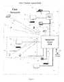
- FIG. 1is a comprehensive view of an integrated smart hub connectivity in a user network.
- FIG. 2shows an integrated smart hub telephony Applications.
- FIG. 3shows an integrated smart hub data Application.
- FIG. 4shows an integrated smart hub multimedia application.
- FIG. 5shows integrated smart hub main components.
- FIG. 6shows an integrated smart hub logical connectivity.
- FIG. 7shows an integrated smart hub data/signal flow diagram
- FIG. 8is a flow chart showing a process of selecting a TV channel.
- FIG. 9is a flow chart showing a process of selecting a video content.
- FIG. 10is a flow chart showing a process of accessing the Internet from a PC, or laptop.
- FIG. 11is a flow chart showing a process for selecting a security status.
- FIG. 12is a flow chart showing a process of making and managing a phone call from TDM Telephone, wireless WiFi Telephone, or a VoIP telephone.
- FIG. 13is a flow chart showing a process of requesting audio content.
- FIG. 14is a flow chart showing a general operation of an integrated smart hub.
- FIG. 1shows a general view 100 of the integrated smart hub 102 .
- the user networkmay be a home, a business, or another facility.
- the FIG. 1shows the integrated smart hub is connected to an analog phone 104 using RG-11 connector/interface for traditional phone service.
- the traditional phone connectivityutilizes two wires or a twisted pair 132 .
- the integrated smart hubis connected to a VoIP telephone 106 using an Ethernet port.
- the VoIP phone 104is connected to the integrated smart hub 102 through an external Ethernet bridge 108 .
- the interface connectoris RG-45 using Category 5 (CAT-6) or Category 5 (CAT-5) wiring 134 .
- Wireless phone 108is used with the integrated smart hub 102 WiFi feature.
- the data connectivity in the user networkconnects appliances and fixtures including Personal Computers (PC), laptops, security cameras, video conferencing cameras, audio speakers, facility security elements and facility automation, management and administration controls elements.
- FIG. 1shows PC 112 is connected to the integrated smart hub 102 using an Ethernet port.
- the PC 112is connected to the integrated smart hub 102 through an external Ethernet bridge 108 .
- the interface connectoris RG-45 using CAT-6 or CAT-5 wiring 134 .
- FIG. 1shows the laptop 114 is wirelessly connected to the integrated smart hub 102 using WiFi feature. If the laptop or any wireless capable application element is distant away from the integrated smart hub 102 , connectivity may be achieved by using wireless repeaters 116 or wireless access point 118 .
- a facility or home security monitoring and managementutilize security cameras, access control and other relay elements.
- a security camera 120is connected wirelessly to the integrated smart hub 102 using WiFi feature as described above.
- the security camera 120 and security elementsmay be connected to a centralized facility automation management and control 122 which is further connected to the integrated smart hub 102 .
- the centralized facility automation management and control 120is connected to the integrated smart hub 102 using Ethernet.
- the centralized facility automation management and control 122may be connected wirelessly to the integrated smart hub 102 using WiFi feature.
- the centralized facility automation management and control 122is external to the integrated smart hub 102 and is a collection source for the home automation devices, and alarm elements.
- the multimediaincludes audio and visual content interaction in the form of TV viewing, audio, gaming, publishing, and computing applications.
- TV applicationsinclude viewing live TV, Pay Per View (PPV), Video On Demand (VOD), recording, storing, and retrieving video contents.
- Audio applicationsinclude listening to a live broadcast, and recorded audio content, recording, storing, and retrieving the audio content.
- Publication and computing applicationsinclude E-commerce, E-health, E-education, video conferencing, gaming, and content sharing applications.
- FIG. 1also shows the integrated smart hub 102 is connected to a TV 124 a using an Ethernet connection.
- the TV 124 ais connected to the integrated smart hub 102 through an external Ethernet bridge 108 .
- the interface connectoris RG-45 and uses CAT-6 or CAT-5 wiring 134 .
- TV 124 bis connected wirelessly to the integrated smart hub 102 using the WiFi feature.
- the TV 124 bmay also be connected directly to the integrated smart hub 102 using CAT 5/6 wiring 134 and RG45 Ethernet port interface.
- TV 124 cis connected to the integrated smart hub 102 using coaxial cable 136 and BNC/TNC 75 ohm port interface.
- FIG. 1shows the integrated smart hub 102 is connected to a remote command and control 128 wireless capability and uses the WiFi feature and Bluetooth.
- the remote command and control 128has a plurality of features and functions including control TVs by peering or mating with a certain TV set through the integrated smart hub 102 , control video camera 130 for video conferencing, enter text command, control and manage a facility such as room temperature, speakers, audio volume level control, playing and controlling video games, managing video and audio programming and contents via the video middleware.
- the remote command and control 128includes VoIP telephone features with a display to answer and make phone calls.
- FIG. 2shows a telephony connectivity feature 200 .
- the integrated, smart hub 202is connected to an analog or Time Domain Multiplexing (TDM) phone 204 via twisted pair 232 or typical telephone wiring with RG-11 jack at both ends.
- the integrated smart hub 202includes a programmed G.711 or G.729 VoIP CODEC feature to convert the signaling protocol to Session Initiation Protocol (SIP) or H323 depending on the carrier used for voice services.
- SIPSession Initiation Protocol
- the VoIP phone 206connects to the integrated smart hub 202 using 10/100 Ethernet protocol over CAT 5/6 cable.
- the interface jackis RG-45 at both ends.
- the signaling and bearer packetsare routed to one dedicated Virtual Local Area Network (VLAN), not shown in FIG.
- VLANVirtual Local Area Network
- the wireless phone 210utilizes VoIP protocol over WiFi.
- the wireless phone 210communicates with the integrated smart hub 202 using the WiFi feature.
- the callis processed similar to the VoIP phone 206 .
- the facsimile machine 238is connected similar to the TDM phone and G711 protocol and is used to process a facsimile transmission.
- FIG. 3shows a data connectivity feature 300 .
- the integrated smart hub 302is connected to a PC 312 , an access point 318 , a centralized facility automation management and control 322 , a security camera 320 and a laptop 314 a using 10/100 Ethernet protocol over CAT 5/6 cable 334 .
- the interface jackis a RG-45 at both ends. Other devices including the security camera 320 a may utilize USB interface ports.
- Alarm and control points 340are collected by the centralized facility automation management and control 322 .
- the signal from each elementis routed to the integrated smart hub 302 internal IP router, not shown in FIG. 3 , for routing the signal to the corresponding internal processor, not shown in FIG. 3 .
- the wireless devicessuch as wireless repeater 316 , wireless centralized facility automation management and control 322 b , wireless security camera 320 b , audio speakers 326 and a laptop 314 b are connected to the integrated smart hub 302 via WiFi capability feature in the integrated smart hub 302 .
- the integrated smart hub 302 internal WiFi transceiverreceives the signals from all the wireless devices, and delivers the signals to an internal IP router via internal signal processor module (not shown in FIG. 3 ).
- FIG. 4shows the multimedia connectivity feature 400 .
- the integrated smart hub 402is connected to a TV 424 a and a laptop 414 using CAT 5/6 cable 434 with RG-45 interface jack at both ends.
- the TV 424 cis connected to the integrated smart hub 402 using 75 ohm coaxial cable 436 with TNC/BNC or proper RG-59 connectors at both ends.
- the TV 424 b , the wireless cameras 430 a and 430 b , wireless speakers 426 and the wireless remote command and control devices 428 a , 428 b and 428 care connected wirelessly to the integrated smart hub 402 using WiFi capability feature in the integrated smart hub 402 .
- the integrated smart hub 402 internal WiFi transceiverreceives the signals from all wireless devices or elements and delivers the signals to an internal IP router via internal signal processor module (not shown in FIG. 4 ).
- the wireless remote command and control devices 428 a , 428 b and 428 care connected also wirelessly to the integrated smart hub 402 using Bluetooth capability feature.
- the integrated smart hub 402 internal Bluetooth transceiverreceives signals from the wireless remote command and control devices 428 a , 428 b and 428 c , and delivers the signals to an internal IP router via internal signal processor module.
- the remote command and control 428has a plurality of functions including a VoIP telephone, a TV/DVR/STB remote control, a game controller, a facility/home admin controller, configuration management, and a monitoring activity display.
- the remote command and control 428has a plurality of features and functions including control TVs by peering with the certain TV set through the integrated smart hub 402 , control video camera 430 for video conferencing, enter text command, control and manage facility elements such as room temperature and speakers audio volume level, play and control video games, and managing video and audio programming and contents via the video middleware.
- the remote command and control 428includes VoIP telephone features with a display to answer and make phone calls.
- the remote command and control 428includes speaker phone and microphone features for speech communications.
- FIG. 5shows an integrated smart hub with its main virtual components 500 .
- the main virtual componentsare connected via the IP gateway router and/or the internal Ethernet bus, and include:
- the IP Gateway Router 572The IP Gateway Router 572 :
- the Controllers 594are the Controllers 594 :
- the Processors 592are the Processors 592 :
- the Set Top Box (STB) Function 5102The Set Top Box (STB) Function 5102 :
- the Video Server 596The Video Server 596 :
- the Games Server 5100The Games Server 5100 :
- the Facility/Home Automation Server 5104The Facility/Home Automation Server 5104 :
- the Content Storage 598The Content Storage 598 :
- the VoIP Codec 584The VoIP Codec 584 :
- the Audio Codec 564The Audio Codec 564 :
- the Bluetooth Transceiver/Modem 560The Bluetooth Transceiver/Modem 560 :
- the WiFi Transceiver/Modem 554The WiFi Transceiver/Modem 554 :
- the VDSL Modem 552is the VDSL Modem 552 :
- the Optical Interfaces 548are identical to the Optical Interfaces 548 :
- the PCMCIA Interface 556The PCMCIA Interface 556 :
- the Telephony Interfaces 562are the Telephony Interfaces 562 :
- the telephone standard interfaces 562are RG-11 Jack types and are present to connected external traditional TDM phones to the integrated smart hub.
- the interfacesare connected internally to the VoIP codec 584 for a call processing.
- the Serial Bus Interfaces 558are identical to the Serial Bus Interfaces 558 :
- Ethernet Interfaces 586The Ethernet Interfaces 586 :
- the MOCA Interface 544The MOCA Interface 544 :
- the Alarm Management 588The Alarm Management 588 :
- the Power Supplies 5106are the Power Supplies 5106 :
- the Optional Access 550
- the objectiveis to equip the integrated smart hub with at least two external network accesses.
- usercan choose FTTH, Ethernet, WiMAX, XDSL, or wireless broadband for public network access.
- FIG. 6depicts a logical connectivity for the integrated smart hub 600 .
- the integrated smart hub and its elements configurationsare stored in controllers 694 a and the back up controller 694 b .
- the signal routing and connectivityare managed by the processors 692 a & 692 b based on the internal data packet information and the routing tables (if the data packet is at distant from the IP router).
- the DC power with different voltagesis fed to all elements from two redundant DC power buses.
- the drawingalso shows dual power-sharing power supplies 6106 a & 6106 b.
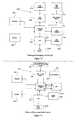
- FIG. 7depicts data/signal flow diagram 700 .
- the one Gigabit Ethernet (Gig-E) busconnects applications programs, alarm processor 788 , a set of internal processors 792 a & 792 b , a set of internal controllers 794 a & 794 b , the media storage 796 , the content storage 798 , game and application server 7100 , STB 7102 , the facility/home automation server 7104 , and the IP gateway router 772 .
- the Ethernet packetsare delivered based on the packet delivery information.
- the IP Gateway router 772 portsare connected to the Gig-e Ethernet bus and other ports as shown in FIG. 7 .
- the IP gateway router 772is responsible for routing traffic between ports based on routing tables that are stored in the integrated smart hub controllers 794 a and 794 b.
- FIG. 8depicts a process flow diagram for selecting a TV channel 800 .
- a userselects a desired live multicast.
- TV channelfrom the remote command and control 828 .
- the wireless command signalis received at the WiFi interface modem (transceiver) 854 and is routed to the IP gateway router 872 .
- the IP gateway router 872routes the command signal to the STB 8102 based the signal packet information and the stored routing table.
- the STB 8102acts as virtual TV tuner, and routes the signal from the ONT 848 to the TV 824 via the IP gateway router 872 .
- the ONT 848receives the video signals or the triple play from the carrier FTTH network 8106 .
- the video signalis encapsulated in a VLAN and the ONT 848 strips the video VLAN (layer 2) and converts it to an Ethernet format.
- the IPTV (Internet Protocol Television) capability of the GPON ONTcan be used to provide digital television services over the ONT data Ethernet port. IPTV services consist of two separate types of traffic:
- An IGMP multicast grouprepresents a TV channel to be watched by some subscribers.
- the subscriber's STBsends IGMP messages to “join” or “leave” its membership in a multicast group.
- the IGMP protocolis terminated by the STB and by the service provider edge router, which may or may not also be in the video content delivery path.
- the provider Optical Line Termination (OLT) and ONTboth perform IGMPv3 (RFC3376) Snooping.
- Snoopingmeans the Layer 2 switches in the OLTs and ONTs, but do not modify, drop, or initiate the IGMP messages, indicating that subscribers want to “join” or “leave” a group membership for a TV channel as these messages pass through in the upstream direction.
- the Layer 2 switches in the OLTs and ONTsforward TV channels downstream to the ONT port where subscribers request those channels.
- Each multicast legis joined to a point where the desired channel is available as close to the subscriber as possible: i.e., in the ONT if possible; otherwise in the OLT. This way, a TV channel is delivered across each link in the network only if needed and no more than once.
- FIG. 9depicts a process flow diagram for selecting a video content 900 .
- a userselects a desired video content (a stored movie for an example) from the on screen menu using the remote command and control 928 .
- the wireless command signalis received at the WiFi interface modem (transceiver) 954 , and is routed to the IP gateway router 972 .
- the IP gateway router 972routes the command signal to the STB 9102 based the signal packet information and the stored routing table (not shown in FIG. 9 ).
- the STB 9102forwards the request to retrieve content from the video server 996 .
- server 996will forward the desired content to the STB 9102 then to the TV 924 via the IP gateway router 972 .
- FIG. 10depicts a process flow diagram for accessing Internet from a PC, or a laptop 1000 .
- a userconnects the PC 1012 to an Ethernet port which is routed to the IP gateway router 1072 .
- the PC 1012is virtually connected directly to the IP gateway router 1072 .
- the laptop 1014is connected wirelessly to the IP gateway router 1072 via the WiFi interface modem (transceiver) 1054 .
- the IP gateway router 1072forwards the user data signal and applications web page to the ONT 1048 .
- the ONT 1048receives the internet access or the triple play from the carrier FTTH network 10106 .
- the data and internetis encapsulated in a VLAN and the ONT 1048 strips the data VLAN (layer 2) and converts it to an Ethernet format. This is typical as it is done today by FTTH providers.
- FIG. 11depicts a process flow diagram for selecting a security status 1100 .
- Usermay request a security status such as a camera view, or an alarm status by using the remote command and control, PC, laptop, and monitor the status using any r attached display or monitor.
- This figureshows an example using the wireless remote command and control 1128 and the TV 1124 .
- the requestis received by the WiFi interface/modem (transceiver), and forward to the IP gateway router 1154 .
- the IP gateway router 1172sends the request to the STB 1102 to requests the middleware to use a window on the TV monitor.
- the STB 1102sends the data requested to the home automation server to process the request and retrieve the video streaming or the alarm status from the external facility management device 1122 .
- the requested data or streaming videois routed to the IP gateway router 1172 and then sent to the STB 1102 .
- the STB 1102sends the requested data or video on a user selected window to the TV 1124 via the IP gateway router 1172 .
- FIG. 12depicts a process flow diagram for making, receiving, and managing a phone call 1200 .
- the flow diagramshows a TDM telephone 1204 a connected to the VoIP CODEC 1284 and a TDM telephone 1204 b connected to the ONT 1248 .
- the traditional telephone callmay be processed via the VoIP CODEC 1284 and/or the ONT 1248 using a standard two wires telephone wiring and RG-11 telephone jack.
- the VoIP applicationprovides voice and data services for Plain Old Telephone Service (POTS) subscriber lines on the VoIP CODEC 1284 .
- POTSPlain Old Telephone Service
- a POTS port on the VoIP CODEC 1284is connected to a telephone 1204 a (or voice services and/or a fax machine or dial-up modem that uses voice-service capabilities for data).
- the SIP-enabled VoIP capabilityenables POTS services using packet switching instead of traditional TDM circuit switching.
- a single User Agent (UA) in the VoIP CODEC 1284provides VoIP capability for subscriber lines.
- the ONT 1248may be provisioned for the POTS-VoIP application instead of the POTS-TDM application, the analog signaling between the ONT 1248 and the subscriber's telephone 1204 b is the same, but the ONT 1248 communicates through an IP packet network, rather than communicating with external Voice Gateway card and the provider's Class 5 switch.
- the call control signaling and the voice bearer trafficmay follow separate paths through the IP network and may be transmitted simultaneously.
- call control signalingwhich uses the Session Initiation Protocol (SIP)
- the ONT 1248 UAcommunicates with a provider VoIP soft switch.
- SIPSession Initiation Protocol
- the ONT 1248 UAmay communicate with a provider media server or a media gateway if the other party (caller) is using the circuit-switched Public Switched Telephone Network (PSTN).
- PSTNPublic Switched Telephone Network
- Provider's VoIP soft switchesunlike traditional TDM circuit switches, do not have to handle the voice bearer traffic.
- some of the VoIP servicesare dependent on performing additional functions within the VoIP CODEC 1284 , or the ONT 1248 themselves.
- the VoIP CODEC 1284 and the ONT 1248provide call progress tones, DTMF signaling tones, and distinctive ringing patterns.
- the VoIP CODEC 1284 and the ONT 1248also enable support of some of the Custom Local Area Switching Service (CLASS) features, such as displaying Caller ID and indicating Call Waiting.
- CLASSCustom Local Area Switching Service
- the VoIP CODEC 1284 and the ONT UAinterwork with a voice application server (part of the soft switch) in accordance with a specified User-Network Interface (UNI) to implement some specific call services.
- UNIUser-Network Interface
- FIG. 12depicts a process flow diagram for a VoIP telephone 1206 connected to the IP gateway router 1272 via a standard Ethernet connection.
- the VoIP telephone (SIP phone) 1206is connected to provider soft switch and performs the same function that described above regarding the SIP signaling and the bearer traffic.
- the VoIP WiFi telephone 1210is connected to a WiFi interface/modem (transceiver) 1254 wirelessly.
- the WiFi interface/modem (transceiver) 1254is connected internally to the IP gateway router 1272 via a standard Ethernet connection.
- the process for managing a telephone call from the VoIP WiFi telephone 1210is the same as the VoIP telephone 1206 .
- FIG. 13depicts a flow diagram for a process of requesting an audio content 1300 .
- This processis similar to the process in FIG. 8 , and FIG. 9 .
- the processis similar to FIG. 9 .
- the audio content signalis delivered to the FTTH network (provider network) 13106 .
- the audio content signalis delivered in IP packets to the ONT 1348 , and passed on to the IP gateway router 1372 , where the STB 13102 manages an internal audio decoding.
- the audio contentthen passed to the WiFi speakers 1326 via the IP gateway router 1372 and the WiFi transceiver 1364 .
- the audio decodingmay be performed at the internal Audio CODEC (not shown in FIG. 13 ), STB 13102 , external PC, external laptop, or other external audio devices.
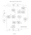
- FIG. 14depicts a process flow diagram for a smart hub for multiple simultaneous transactional operation 1400 .
- the integrated smart huballows for multiple operations and transactions simultaneously. For example, multiple users may request multiple video contents to be sent to multiple TV sets simultaneously, while other users conduct phone calls or requesting internet downloads at the same time.
- the multitaskingis achieved by the software programs that reside on the processor module, stored configurations in the controller module, and routing tables on the IP gateway router.
- the standard IP packetsare routed between virtual ports in the internal elements based on the address information in the header. For commands and requests for transaction or operation, the payload in the IP packet delivers the command information to the proper addressed element for execution.
- Each remote command and controlis wirelessly connected to the integrated smart hub via secure WiFi feature. For example in FIG.
- a usersends a request for a content to be displayed on TV set 14024 from the remote command and control 14028 , which is connected to the WiFi transceiver 14054 .
- the requestis routed through the IP gateway router to the STB 14102 for execution.
- the STB 14102sends a request to the video server 14096 to retrieve and send the specific content to TV set 14024 via the IP gateway router 14072 , and the Ethernet interface 14086 a .
- FIG. 14shows two IP gateway routers 14072 , there is only one IP gateway router 14072 and this was done for illustration clarity only.
- the Embedded middleware that resides in the STB 14102allows for many video features and interaction simultaneously, such as display menu, and multiple window displays such as window for games, window for video conferencing, and window for weather channel, and content review from a menu on the same TV.
- the useralso may request a live streaming video from a channel list by requesting the channel from the remote command and control 14028 .
- the requestwill be routed to the STB 14102 through the IP gateway router 14072 .
- the STB 14102is connected to the ONT 14048 through the IP gateway router 14072 .
- the streaming multicast video channelis delivered to TV 14024 via the IP gateway router and the Ethernet interface 14086 a , as stated in FIG. 8 .
- laptop 14014may use laptop 14014 to request an internet content download simultaneously, since the laptop is connected to the internet by assigning a dynamic IP address, through the IP gateway router 14072 , ONT 14048 and to the provider network 14106 .
- Another usermay do the same function using a PC that connected to the provider network through Ethernet interface 14086 , IP gateway router 14072 , and the ONT 14048 .
- Another usermay make phone calls using the VoIP WiFi telephone 14010 or the wired VoIP telephone 14006 using the same process as stated in FIG. 12 .
- the TDM phone 14004may utilize the VoIP CODEC 14084 or the ONT 14048 to manage telephone calls as described in FIG. 12 .
- the usersmay also monitor the facility alarms from the alarm elements hub 14022 and using the security camera 14020 while watching TV or using any laptop applications.
- the usersmay also send commands from the remote command and control 14028 to change the facility condition such as temperature using the facility automation server 14104 , which is connected to the specific apparatus (not shown in the figure) that needs to be adjusted or changed for a desired condition, or an action.
Landscapes
- Engineering & Computer Science (AREA)
- Automation & Control Theory (AREA)
- Computer Networks & Wireless Communication (AREA)
- Signal Processing (AREA)
- Computing Systems (AREA)
- Multimedia (AREA)
- Telephonic Communication Services (AREA)
- Data Exchanges In Wide-Area Networks (AREA)
Abstract
Description
- watching a streaming movie or live TV on a laptop or a TV screen,
- text messaging from the remote command and control, using the remote command and control display or a TV set,
- obtaining a Caller Identification (Caller ID) and managing telephony features on a TV set while watching a TV program,
- Accessing multiple screen windows for multi-activity on any display including a TV, or a laptop with the STB middleware features,
- interacting with PC application from a TV monitor,
- managing a phone call from a TDM phone, VoIP phone, a remote command and control, and a PC, or a laptop,
- making a video conference from a PC, a laptop or using a TV set, camera, or a remote command and control,
- monitoring a plurality of security cameras in different windows on a TV, PC, or a laptop,
- communicating using the wireless broadband feature,
- managing facility or home automation and security from a plurality of local devices, such as the remote command and control, and a laptop, or a PC,
- Managing and controlling music, video, telephony, and data from any interactive device with a display.
- The
IP gateway router 572 is an internal element and it routes the signal based on routing tables that determine configuration of the integrated smart hub and stored in thecontroller module 594. Primarily, it delivers IP packets between its ports based on the address destination and the routing tables. It connects the integrated smart hub interface ports to the proper application processors, server, codec or other internal components.
- The
- There is a main controller and a back up controller. The integrated smart hub configurations, applications configurations, ports configurations, intelligent processing, and all internal elements configurations are stored in the main controller, and backup copies are stored in the backup controller. There is a link between the two controllers for updating and checking for each other's performance.
- There are two main processors. These main processors conduct the integrated smart hub applications and operations.
- The
STB 5102 function component includes multimedia middleware, witch manages displayed menu, video content, streaming video broadcast, recording, content retrieving, audio streaming, audio content management, and playback stored content on the STB's Random Access Memory (RAM) or thevideo server 596. TheSTB 5102 also includes IPTV decoder which converts the video content from MPEG-2 and MPRG-4 to NTSC, PAL, SCAM or other digital television format. A user may store and retrieve contents from the remote command and control and using the display menu. TheSTB 5102 store retrieves content on thevideo server 596 orcontent server 598 based on the middleware and the commands initiated by the user. TheSTB 5102 includes at least 256 MB of RAM which makes the integrated smart hub capable of handling and displaying quality 3 Dimension (3D) High Definition TV (HDTV) on the attached TV sets, displays quality graphics and manages sophisticated internet video games.
- The
- The
video server 596 stores and manages the video content. The video server receives the commands from theSTB 5102 and directs the stored content to theSTB 5102. Thevideo server 596 has multi-sector solid-state contents storage and storage management processor. Initially, a minimum of 8 storage sectors are included with 128 GB of memory for each storage sector. The number of memory sectors may be expanded for future storage needs.
- The
- The
game server 5100 is used for storing and managing the video games. Thegame server 5100 receives commands from the remote command and control andSTB 5102. Thegame server 5100 has solid-state content storage and game management processors. Thegame server 5100 has 64 GB of solid-state memory and 256 MB of RAM. Depending on the game software, the user downloads the games from the interne or through any peripheral attached to one of the integrated smart hub serial ports.
- The
- The facility/
home automation server 5104 function is to manage facility alarms and controls, and as well as other aspects such as air-condition, heating, and shutters. Since there is a significant customization due to different requirements and different devices' specifications, this server has to have a customized configuration. The customized configuration is based on the software and to an extent for the required processing. There are off the shelf products that may be easily integrated with the integrated smart hub.
- The facility/
- The
content storage 598 has a flash driver and stores content that a user desires. Contents include personal files, images, video clips, publication, and music. The integrated smart hub'sprocessor 592 and internal flash driver (not shown inFIG. 5 ) will manage the content storage based on the user commands from the remote command and control or any attached PC or laptop. The content storage element will act as flash drive and the content can be displayed on any attached display device, such as PC, laptop, TV or the remote command and control. Thecontent storage 598 has multi-sector solid-state memory. Initially, a minimum of 4 storage sectors are included with 128 GB of memory for each. The number of memory sector may be expanded for future storage needs.
- The
- The
VoIP codec 584 acts as VoIP modem and encodes and decodes the telephone analog/TDM voice into a VoIP standard format such as G.711, G.729 and the signaling into a SIP format to be carried over public or private internet service. Telephony features are dependent on the loaded software and the service provider. For facsimile transmission, G.711 is used.
- The
- The
audio codec 564 converts the analog audio into standard digital audio format for processing and distribution to local interfaces as configured by a user.
- The
- The Bluetooth transceiver/
modem 560 converts the wireless Bluetooth format to a standard digital format.
- The Bluetooth transceiver/
- The WiFi transceiver/
modem 554 converts the wireless WiFi format into a standard format.
- The WiFi transceiver/
- The
VDSL modem 552 converts the VDSL format to a standard digital format. Primarily, VDSL2 is used due to its capability of delivering a higher bandwidth (50 Mb/s). VDSL2 format/modulation is an access method used by carriers to carry multimedia or triple play traffic over phone lines.
- The
- The
optical interface 548 convert the light-wave signal that carried over optical fiber interface to electric signal in a form of data stream using Ethernet standard format. One interface will act as ONT for carriers' GPON standard access services, and the other optical interfaces may provide local interface for intra facility communications over a single or multimode optical fiber.
- The
- This interface will provide for memory or flash driver to upload or download contents to and from the integrated smart hub.
- The
serial bus interface 558 such as USB and other legacy serial interfaces connect the external devices to the internal corresponding application processors via theIP gateway router 572. In this invention, multiple USB interfaces are used in an integrated smart hub.
- The
- Multiple 10/100 Mb standard Ethernet interfaces586 is utilized to connect external devices and services to the corresponding internal applications and processors via the
IP gateway router 572.
- Multiple 10/100 Mb standard Ethernet interfaces586 is utilized to connect external devices and services to the corresponding internal applications and processors via the
- This standard interface is used for traditional video services and to carry the multimedia signal between the integrated smart hub and the traditional TV sets.
- This component is used to collect an internal device's performance and alarms, and to provide for intelligent decision for each interface performance characteristics. Any performance degradation triggers a visible alarm and display an error message with codes on any of the integrated smart hub attached displays.
- There are two internal load-sharing power supplies. The power supplies input is a commercial Alternate Current (AC). The AC voltage range from 100 VAC to 240 VAC, and the power cycle ranges from 50 Hertz (HZ) to 60 HZ. There is multiple output Direct Current (DC) voltage that range from 0.5 VDC and 20 VDC to support all internal modules. The power supplies include protection fuses, backup batteries, and control module. The batteries are designed to support a phone life line for up to 8 hours. The control module manages the load-sharing, switching to a single power supply if one power supply fails and switch to the backup batteries when the commercial AC fails.
- The integrated smart hub is having optional slots to accommodate wireless broadband such as LTE or GSM-
G4 transceiver 550aand WiMAX modem (IEEE 802.16 wireless broadband standards)550b.
- The integrated smart hub is having optional slots to accommodate wireless broadband such as LTE or GSM-
- The streaming IP video, which is multicast downstream to a dynamically changing a set of subscribers watching a TV channel.
- The channel-change traffic uses Internet Group Management Protocol (IGMP).
Claims (12)
Priority Applications (1)
| Application Number | Priority Date | Filing Date | Title |
|---|---|---|---|
| US12/636,678US8724639B2 (en) | 2010-02-26 | 2010-02-26 | Smart home hub |
Applications Claiming Priority (1)
| Application Number | Priority Date | Filing Date | Title |
|---|---|---|---|
| US12/636,678US8724639B2 (en) | 2010-02-26 | 2010-02-26 | Smart home hub |
Publications (2)
| Publication Number | Publication Date |
|---|---|
| US20110211584A1 US20110211584A1 (en) | 2011-09-01 |
| US8724639B2true US8724639B2 (en) | 2014-05-13 |
Family
ID=44505239
Family Applications (1)
| Application Number | Title | Priority Date | Filing Date |
|---|---|---|---|
| US12/636,678Expired - Fee RelatedUS8724639B2 (en) | 2010-02-26 | 2010-02-26 | Smart home hub |
Country Status (1)
| Country | Link |
|---|---|
| US (1) | US8724639B2 (en) |
Cited By (18)
| Publication number | Priority date | Publication date | Assignee | Title |
|---|---|---|---|---|
| US20140028448A1 (en)* | 2012-07-23 | 2014-01-30 | Brian W. Karam | Entertainment, lighting and climate control system |
| US9219613B1 (en)* | 2011-11-04 | 2015-12-22 | Arris Enterprises, Inc. | Alternative set-top gateway source for DOCSIS 3.0 |
| US9635129B2 (en) | 2014-09-10 | 2017-04-25 | At&T Intellectual Property I, L.P. | Automatic application discovery, download, integration and launch |
| US9788302B2 (en) | 2014-12-01 | 2017-10-10 | At&T Intellectual Property I, L.P. | Method and apparatus for delivering media content and backup media content using multiple networks |
| US9794701B2 (en) | 2012-08-31 | 2017-10-17 | Starkey Laboratories, Inc. | Gateway for a wireless hearing assistance device |
| US9807459B2 (en) | 2015-05-14 | 2017-10-31 | At&T Intellectual Property I, L.P. | Media interface device |
| US9940928B2 (en) | 2015-09-24 | 2018-04-10 | Starkey Laboratories, Inc. | Method and apparatus for using hearing assistance device as voice controller |
| US10038975B1 (en) | 2016-11-10 | 2018-07-31 | Wells Fargo Bank, N.A. | Provisioning news items |
| US10146838B2 (en) | 2014-09-30 | 2018-12-04 | At&T Intellectual Property I, L.P. | Contextual management of client devices |
| US10182133B2 (en) | 2014-12-15 | 2019-01-15 | Xiaomi Inc. | Method and device for starting application |
| US10462651B1 (en)* | 2010-05-18 | 2019-10-29 | Electric Mirror, Llc | Apparatuses and methods for streaming audio and video |
| US10735686B2 (en) | 2010-12-15 | 2020-08-04 | Microsoft Technology Licensing, Llc | Enhanced content consumption |
| US10917336B2 (en) | 2015-08-31 | 2021-02-09 | Microsoft Technology Licensing, Llc | Routing device with independent service subsystem |
| US11070869B2 (en) | 2018-11-28 | 2021-07-20 | Samsung Eletrônica da Amazônia Ltda. | Method for controlling Internet of Things devices with digital TV receivers using transmission from a broadcaster in a transport stream flow |
| US11627012B2 (en) | 2018-10-09 | 2023-04-11 | NewTekSol, LLC | Home automation management system |
| US11831952B2 (en) | 2008-09-10 | 2023-11-28 | DISH Technologies L.L.C. | Virtual set-top box |
| US11936492B2 (en) | 2019-09-11 | 2024-03-19 | Savant Systems, Inc. | Redundant control for wireless devices in a home automation system |
| US12250539B2 (en) | 2018-03-21 | 2025-03-11 | Samsung Electronics Co., Ltd. | Method and device for authenticating device using wireless LAN service |
Families Citing this family (91)
| Publication number | Priority date | Publication date | Assignee | Title |
|---|---|---|---|---|
| US20140071818A1 (en)* | 2004-07-16 | 2014-03-13 | Virginia Innovation Sciences, Inc. | Method and system for efficient communication |
| US9554061B1 (en) | 2006-12-15 | 2017-01-24 | Proctor Consulting LLP | Smart hub |
| JP5792424B2 (en)* | 2009-07-03 | 2015-10-14 | ソニー株式会社 | MAP INFORMATION DISPLAY DEVICE, MAP INFORMATION DISPLAY METHOD, AND PROGRAM |
| US8509954B2 (en) | 2009-08-21 | 2013-08-13 | Allure Energy, Inc. | Energy management system and method |
| US8498749B2 (en) | 2009-08-21 | 2013-07-30 | Allure Energy, Inc. | Method for zone based energy management system with scalable map interface |
| US9209652B2 (en) | 2009-08-21 | 2015-12-08 | Allure Energy, Inc. | Mobile device with scalable map interface for zone based energy management |
| US9838255B2 (en) | 2009-08-21 | 2017-12-05 | Samsung Electronics Co., Ltd. | Mobile demand response energy management system with proximity control |
| US8879989B2 (en)* | 2010-03-03 | 2014-11-04 | VIZIO Inc. | System, method and apparatus for displaying caller-identification |
| US9143739B2 (en) | 2010-05-07 | 2015-09-22 | Iwatchlife, Inc. | Video analytics with burst-like transmission of video data |
| US20110302283A1 (en)* | 2010-06-03 | 2011-12-08 | Niclas Nors | Methods And Arrangements In A Passive Optical Network |
| US8428232B2 (en)* | 2010-06-18 | 2013-04-23 | Comcast Cable Communications, Llc | Centralized communication hub for displaying calls and messages on a display |
| CA2743949A1 (en)* | 2010-06-22 | 2011-12-22 | Iwatchlife | System and method of local resource delivery |
| CA2748065A1 (en) | 2010-08-04 | 2012-02-04 | Iwatchlife Inc. | Method and system for locating an individual |
| US8885007B2 (en) | 2010-08-04 | 2014-11-11 | Iwatchlife, Inc. | Method and system for initiating communication via a communication network |
| US20120054667A1 (en)* | 2010-08-31 | 2012-03-01 | Blackboard Inc. | Separate and simultaneous control of windows in windowing systems |
| US8955022B2 (en) | 2010-09-15 | 2015-02-10 | Comcast Cable Communications, Llc | Securing property |
| US8804533B2 (en)* | 2010-12-28 | 2014-08-12 | Broadcom Corporation | Techniques for Wi-Fi acceleration in residential gateways |
| WO2012131727A1 (en)* | 2011-03-31 | 2012-10-04 | Lukup Media Pvt Ltd | System and method for creating and delivering platform independent interactive applications on user devices |
| JP5817242B2 (en)* | 2011-06-21 | 2015-11-18 | オンキヨー株式会社 | Content processing system, content processing apparatus, and program thereof |
| MX2013001773A (en) | 2011-07-18 | 2013-04-03 | Panasonic Corp | Image encoding method, image decoding method, image encoding apparatus, image decoding apparatus, and image encoding/decoding apparatus. |
| EP2751955B1 (en)* | 2011-08-30 | 2019-11-13 | Samsung Electronics Co., Ltd. | Resource manager and method for communicating resource management information for smart energy and media resources |
| TWI478613B (en)* | 2011-09-26 | 2015-03-21 | Connection establishing management methods and related apparatuses | |
| US20130091308A1 (en)* | 2011-10-10 | 2013-04-11 | Hanwha Solution & Consulting Co., Ltd. | Multi protocol adapter |
| CN102448191A (en)* | 2011-11-16 | 2012-05-09 | 上海大亚科技有限公司 | EOC terminal equipment capable of realizing WIFI (Wireless Fidelity) function |
| TWM426233U (en)* | 2011-12-06 | 2012-04-01 | Tuton Technology Co Ltd | Smart TV with built-in network sharing module |
| US9894501B2 (en)* | 2012-03-30 | 2018-02-13 | Arris Enterprises Llc | Handover of on-hold session between fixed packet network and cellular network |
| CN102651915B (en)* | 2012-05-11 | 2015-06-03 | 卢泳 | Intelligent wireless router and wireless communication system |
| US10536361B2 (en)* | 2012-06-27 | 2020-01-14 | Ubiquiti Inc. | Method and apparatus for monitoring and processing sensor data from an electrical outlet |
| US20140341408A1 (en)* | 2012-08-31 | 2014-11-20 | Starkey Laboratories, Inc. | Method and apparatus for conveying information from home appliances to a hearing assistance device |
| US9208676B2 (en)* | 2013-03-14 | 2015-12-08 | Google Inc. | Devices, methods, and associated information processing for security in a smart-sensored home |
| CN102938718B (en)* | 2012-10-19 | 2016-03-30 | 中兴通讯股份有限公司 | A kind of home gateway and intelligent terminal integrated system and communication means thereof |
| EP2922285A4 (en)* | 2012-11-13 | 2016-07-13 | Shenzhen Itoo Wyrestorm Technology Ltd | Smart home access device |
| GB2507996A (en)* | 2012-11-16 | 2014-05-21 | Promethean Ltd | Network based collaborative interactive activity between devices and users |
| KR101934099B1 (en)* | 2012-12-14 | 2019-01-02 | 삼성전자주식회사 | Contents playing apparatus, method for providing user interface using the contents playing apparatus, network server and method for controllong the network server |
| US9716530B2 (en) | 2013-01-07 | 2017-07-25 | Samsung Electronics Co., Ltd. | Home automation using near field communication |
| US9485468B2 (en)* | 2013-01-08 | 2016-11-01 | Angelo J. Pino, JR. | System, method and device for providing communications |
| US10063499B2 (en) | 2013-03-07 | 2018-08-28 | Samsung Electronics Co., Ltd. | Non-cloud based communication platform for an environment control system |
| US20140373074A1 (en) | 2013-06-12 | 2014-12-18 | Vivint, Inc. | Set top box automation |
| TWI504292B (en)* | 2013-06-19 | 2015-10-11 | D Link Corp | Network camera with network repeater function and its setting method |
| US10939155B2 (en)* | 2013-11-19 | 2021-03-02 | Comcast Cable Communications, Llc | Premises automation control |
| US20150156538A1 (en)* | 2013-12-02 | 2015-06-04 | Vishwas Godbole | Portable, multi-channel, multi-user, online streaming and recording and offline streaming and playback device |
| KR101504665B1 (en) | 2013-12-31 | 2015-03-20 | 주식회사 케이티 | Network management supporting method, apparatus thereof, and system thereof |
| CN106464551A (en) | 2014-01-06 | 2017-02-22 | 魅力能源公司 | System, device, and apparatus for coordinating environments using network devices and remote sensory information |
| SG11201605494QA (en) | 2014-01-06 | 2016-08-30 | Allure Energy Inc | System, device, and apparatus for coordinating environments using network devices and remote sensory information |
| US11310614B2 (en) | 2014-01-17 | 2022-04-19 | Proctor Consulting, LLC | Smart hub |
| CN106462168B (en)* | 2014-03-20 | 2021-07-13 | 麦乐诺尔股份有限公司 | Wireless device, system and method for controlling a valve |
| US20150296258A1 (en)* | 2014-04-14 | 2015-10-15 | Nagravision S.A. | Media gateway for scheduling content |
| US9870661B2 (en)* | 2014-04-26 | 2018-01-16 | At&T Intellectual Property I, L.P. | Access control system |
| DE102014009256A1 (en) | 2014-06-20 | 2015-12-24 | Audi Ag | Routers and methods for receiving and distributing data |
| CN104079457B (en)* | 2014-07-10 | 2017-04-12 | 上海凡米智能科技有限公司 | Intelligent home system containing intelligent home central control U shield |
| US20160028828A1 (en)* | 2014-07-25 | 2016-01-28 | Oort Europe S.A. | Hub and cloud based control and automation |
| JP6270658B2 (en)* | 2014-08-06 | 2018-01-31 | 三菱電機株式会社 | Air conditioner indoor unit |
| CN105589427A (en)* | 2014-10-24 | 2016-05-18 | 深圳市拔超科技有限公司 | Intelligence control system with integration of matrix and power supply management and server equipment |
| WO2016088214A1 (en)* | 2014-12-03 | 2016-06-09 | 富士機械製造株式会社 | Multiplex communication system and work machine |
| CN104539548B (en)* | 2014-12-15 | 2018-05-08 | 小米科技有限责任公司 | Using startup method and device |
| US9860681B2 (en)* | 2015-01-06 | 2018-01-02 | Afero, Inc. | System and method for selecting a cell carrier to connect an IOT hub |
| US9774497B2 (en) | 2015-01-06 | 2017-09-26 | Afero, Inc. | System and method for implementing internet of things (IOT) remote control applications |
| US9729340B2 (en) | 2015-01-06 | 2017-08-08 | Afero, Inc. | System and method for notifying a user of conditions associated with an internet-of-things (IoT) hub |
| US10816944B2 (en) | 2015-01-06 | 2020-10-27 | Afero, Inc. | System and method for using data collected from internet-of-things (IoT) sensors to disable IoT-enabled home devices |
| US9774507B2 (en) | 2015-01-06 | 2017-09-26 | Afero, Inc. | System and method for collecting and utilizing user behavior data within an IoT system |
| US9933768B2 (en) | 2015-01-06 | 2018-04-03 | Afero, Inc. | System and method for implementing internet of things (IOT) remote control applications |
| US10031722B1 (en) | 2015-03-17 | 2018-07-24 | Amazon Technologies, Inc. | Grouping devices for voice control |
| US11749249B2 (en) | 2015-05-29 | 2023-09-05 | Sound United, Llc. | System and method for integrating a home media system and other home systems |
| US9706320B2 (en) | 2015-05-29 | 2017-07-11 | Sound United, LLC | System and method for providing user location-based multi-zone media |
| US10657949B2 (en)* | 2015-05-29 | 2020-05-19 | Sound United, LLC | System and method for integrating a home media system and other home systems |
| US10655951B1 (en) | 2015-06-25 | 2020-05-19 | Amazon Technologies, Inc. | Determining relative positions of user devices |
| US10365620B1 (en) | 2015-06-30 | 2019-07-30 | Amazon Technologies, Inc. | Interoperability of secondary-device hubs |
| CN105182759A (en)* | 2015-07-20 | 2015-12-23 | 成都弘毅天承科技有限公司 | Smart home security protection and fire extinguishing control system |
| CN105182758A (en)* | 2015-07-20 | 2015-12-23 | 成都弘毅天承科技有限公司 | Smart home household appliance and curtain control system |
| CN106886279A (en)* | 2015-12-16 | 2017-06-23 | 华为技术有限公司 | A kind of control method and device |
| US9858927B2 (en) | 2016-02-12 | 2018-01-02 | Amazon Technologies, Inc | Processing spoken commands to control distributed audio outputs |
| US10936109B2 (en) | 2016-03-31 | 2021-03-02 | Huawei Technologies Co., Ltd. | Terminal device and terminal device control method |
| US11329772B2 (en)* | 2016-05-17 | 2022-05-10 | Sure-Fi, Inc. | Redundant network system |
| CN106656698A (en)* | 2016-12-29 | 2017-05-10 | 重庆金鑫智慧科技有限公司 | System for ensuring control on smart home without network |
| US10166465B2 (en) | 2017-01-20 | 2019-01-01 | Essential Products, Inc. | Contextual user interface based on video game playback |
| US10359993B2 (en) | 2017-01-20 | 2019-07-23 | Essential Products, Inc. | Contextual user interface based on environment |
| CN108370459B (en)* | 2017-04-20 | 2021-12-03 | 北京小米移动软件有限公司 | Equipment management method and device |
| US11224295B2 (en)* | 2017-05-22 | 2022-01-18 | Werner Media Partners, LLC | Smart adjustable bed system |
| CN107682242A (en)* | 2017-09-29 | 2018-02-09 | 珠海市领创智能物联网研究院有限公司 | A kind of smart home based on Internet of Things control |
| US10620798B2 (en) | 2017-10-21 | 2020-04-14 | Mordechai Teicher | Autonomously cooperating smart devices |
| US10742442B2 (en) | 2017-10-21 | 2020-08-11 | Mordechai Teicher | Cluster of smart devices operable in hub-based and hub-less modes |
| US10025471B1 (en) | 2017-10-21 | 2018-07-17 | Mordechai Teicher | User-programmable cluster of smart devices |
| US10325596B1 (en)* | 2018-05-25 | 2019-06-18 | Bao Tran | Voice control of appliances |
| US10848815B2 (en)* | 2018-08-23 | 2020-11-24 | Dish Network L.L.C. | Outputting a message during downloading or buffering |
| US10965484B2 (en)* | 2018-12-21 | 2021-03-30 | Opendoor Labs Inc. | Fleet of home electronic systems |
| CN111654764B (en)* | 2019-03-04 | 2024-07-19 | 深圳市茁壮网络股份有限公司 | Terminal management method and system |
| CN110198362B (en)* | 2019-05-05 | 2021-08-20 | 华为技术有限公司 | A method and system for adding smart home equipment to contacts |
| US11823817B2 (en)* | 2020-02-04 | 2023-11-21 | Structured Home Wiring Direct, LLC | Composite hybrid cables and methods of manufacturing and installing the same |
| CN112235617B (en)* | 2020-09-25 | 2022-07-08 | 烽火通信科技股份有限公司 | Set-top box WiFi-based networking method for realizing easy mesh and set-top box |
| US12066216B2 (en)* | 2020-12-21 | 2024-08-20 | Rinnai America Corporation | Water heater building management system gateway |
| US12171047B2 (en)* | 2022-06-27 | 2024-12-17 | Red Hat, Inc. | Relative location conditioned staged download service for internet-of-things (IoTs) |
Citations (14)
| Publication number | Priority date | Publication date | Assignee | Title |
|---|---|---|---|---|
| US6317489B1 (en)* | 1996-07-29 | 2001-11-13 | Elite Access Systems, Inc. | Entry phone apparatus and method with improved alphabetical access |
| US20060218575A1 (en)* | 2003-06-26 | 2006-09-28 | Blair Ronald L | Parental monitoring of digital content |
| US20070217436A1 (en)* | 2006-03-16 | 2007-09-20 | Markley Jeffrey P | Methods and apparatus for centralized content and data delivery |
| US20080056718A1 (en)* | 2000-07-13 | 2008-03-06 | L-3 Communications Integrated Systems L.P. | Synchronous collapsed ring architecture for real-time signal switching and distribution |
| US20080117922A1 (en)* | 2006-11-16 | 2008-05-22 | Sbc Knowledge Ventures, Lp | Home automation system and method including remote media access |
| US20080134239A1 (en)* | 1998-07-29 | 2008-06-05 | Starsight Telecast Inc. | Multiple interactive electronic program guide system and methods |
| US20090158370A1 (en)* | 2007-12-18 | 2009-06-18 | At&T Knowledge Ventures, Lp | Set-Top Box-Based TV Streaming and Redirecting |
| US20100064324A1 (en)* | 2008-09-10 | 2010-03-11 | Geraint Jenkin | Dynamic video source selection |
| US20100103943A1 (en)* | 2008-10-29 | 2010-04-29 | Edward Walter | Methods and apparatus to provide power over an ethernet-based network to a wide area network access device |
| US20100278345A1 (en)* | 2009-05-04 | 2010-11-04 | Thomas Matthieu Alsina | Method and apparatus for proximity based pairing of mobile devices |
| US20110107379A1 (en)* | 2009-10-30 | 2011-05-05 | Lajoie Michael L | Methods and apparatus for packetized content delivery over a content delivery network |
| US20110131617A1 (en)* | 2009-11-30 | 2011-06-02 | At&T Intellectual Property I, L.P. | Noise Reduction Apparatus with Isolation Transformers in an Internet Protocol Television System |
| US8031726B2 (en)* | 2006-12-29 | 2011-10-04 | Prodea Systems, Inc. | Billing, alarm, statistics and log information handling in multi-services gateway device at user premises |
| US20110296481A1 (en)* | 2007-06-13 | 2011-12-01 | Chris Cholas | Premises gateway apparatus and methods for use in a content-based network |
- 2010
- 2010-02-26USUS12/636,678patent/US8724639B2/ennot_activeExpired - Fee Related
Patent Citations (14)
| Publication number | Priority date | Publication date | Assignee | Title |
|---|---|---|---|---|
| US6317489B1 (en)* | 1996-07-29 | 2001-11-13 | Elite Access Systems, Inc. | Entry phone apparatus and method with improved alphabetical access |
| US20080134239A1 (en)* | 1998-07-29 | 2008-06-05 | Starsight Telecast Inc. | Multiple interactive electronic program guide system and methods |
| US20080056718A1 (en)* | 2000-07-13 | 2008-03-06 | L-3 Communications Integrated Systems L.P. | Synchronous collapsed ring architecture for real-time signal switching and distribution |
| US20060218575A1 (en)* | 2003-06-26 | 2006-09-28 | Blair Ronald L | Parental monitoring of digital content |
| US20070217436A1 (en)* | 2006-03-16 | 2007-09-20 | Markley Jeffrey P | Methods and apparatus for centralized content and data delivery |
| US20080117922A1 (en)* | 2006-11-16 | 2008-05-22 | Sbc Knowledge Ventures, Lp | Home automation system and method including remote media access |
| US8031726B2 (en)* | 2006-12-29 | 2011-10-04 | Prodea Systems, Inc. | Billing, alarm, statistics and log information handling in multi-services gateway device at user premises |
| US20110296481A1 (en)* | 2007-06-13 | 2011-12-01 | Chris Cholas | Premises gateway apparatus and methods for use in a content-based network |
| US20090158370A1 (en)* | 2007-12-18 | 2009-06-18 | At&T Knowledge Ventures, Lp | Set-Top Box-Based TV Streaming and Redirecting |
| US20100064324A1 (en)* | 2008-09-10 | 2010-03-11 | Geraint Jenkin | Dynamic video source selection |
| US20100103943A1 (en)* | 2008-10-29 | 2010-04-29 | Edward Walter | Methods and apparatus to provide power over an ethernet-based network to a wide area network access device |
| US20100278345A1 (en)* | 2009-05-04 | 2010-11-04 | Thomas Matthieu Alsina | Method and apparatus for proximity based pairing of mobile devices |
| US20110107379A1 (en)* | 2009-10-30 | 2011-05-05 | Lajoie Michael L | Methods and apparatus for packetized content delivery over a content delivery network |
| US20110131617A1 (en)* | 2009-11-30 | 2011-06-02 | At&T Intellectual Property I, L.P. | Noise Reduction Apparatus with Isolation Transformers in an Internet Protocol Television System |
Cited By (26)
| Publication number | Priority date | Publication date | Assignee | Title |
|---|---|---|---|---|
| US12273592B2 (en) | 2008-09-10 | 2025-04-08 | DISH Technologies L.L.C. | Virtual set-top box |
| US11831952B2 (en) | 2008-09-10 | 2023-11-28 | DISH Technologies L.L.C. | Virtual set-top box |
| US10972905B1 (en)* | 2010-05-18 | 2021-04-06 | Electric Mirror, Llc | Apparatuses and methods for streaming audio and video |
| US10462651B1 (en)* | 2010-05-18 | 2019-10-29 | Electric Mirror, Llc | Apparatuses and methods for streaming audio and video |
| US10735686B2 (en) | 2010-12-15 | 2020-08-04 | Microsoft Technology Licensing, Llc | Enhanced content consumption |
| US9219613B1 (en)* | 2011-11-04 | 2015-12-22 | Arris Enterprises, Inc. | Alternative set-top gateway source for DOCSIS 3.0 |
| US9217995B2 (en)* | 2012-07-23 | 2015-12-22 | Brian W. Karam | Entertainment, lighting and climate control system |
| US20140028448A1 (en)* | 2012-07-23 | 2014-01-30 | Brian W. Karam | Entertainment, lighting and climate control system |
| US9794701B2 (en) | 2012-08-31 | 2017-10-17 | Starkey Laboratories, Inc. | Gateway for a wireless hearing assistance device |
| US9635129B2 (en) | 2014-09-10 | 2017-04-25 | At&T Intellectual Property I, L.P. | Automatic application discovery, download, integration and launch |
| US10146838B2 (en) | 2014-09-30 | 2018-12-04 | At&T Intellectual Property I, L.P. | Contextual management of client devices |
| US10341989B2 (en) | 2014-12-01 | 2019-07-02 | At&T Intellectual Property I, L.P. | Method and apparatus for delivering media content and backup media content using multiple networks |
| US9788302B2 (en) | 2014-12-01 | 2017-10-10 | At&T Intellectual Property I, L.P. | Method and apparatus for delivering media content and backup media content using multiple networks |
| US10182133B2 (en) | 2014-12-15 | 2019-01-15 | Xiaomi Inc. | Method and device for starting application |
| US9807459B2 (en) | 2015-05-14 | 2017-10-31 | At&T Intellectual Property I, L.P. | Media interface device |
| US10757479B2 (en) | 2015-05-14 | 2020-08-25 | At&T Intellectual Property I, L.P. | Media interface device |
| US10917336B2 (en) | 2015-08-31 | 2021-02-09 | Microsoft Technology Licensing, Llc | Routing device with independent service subsystem |
| US10453458B2 (en) | 2015-09-24 | 2019-10-22 | Starkey Laboratories, Inc. | Method and apparatus for using hearing assistance device as voice controller |
| US11361766B2 (en) | 2015-09-24 | 2022-06-14 | Starkey Laboratories, Inc. | Method and apparatus for using hearing assistance device as voice controller |
| US9940928B2 (en) | 2015-09-24 | 2018-04-10 | Starkey Laboratories, Inc. | Method and apparatus for using hearing assistance device as voice controller |
| US10595159B1 (en) | 2016-11-10 | 2020-03-17 | Wells Fargo Bank, N.A. | Provisioning news items |
| US10038975B1 (en) | 2016-11-10 | 2018-07-31 | Wells Fargo Bank, N.A. | Provisioning news items |
| US12250539B2 (en) | 2018-03-21 | 2025-03-11 | Samsung Electronics Co., Ltd. | Method and device for authenticating device using wireless LAN service |
| US11627012B2 (en) | 2018-10-09 | 2023-04-11 | NewTekSol, LLC | Home automation management system |
| US11070869B2 (en) | 2018-11-28 | 2021-07-20 | Samsung Eletrônica da Amazônia Ltda. | Method for controlling Internet of Things devices with digital TV receivers using transmission from a broadcaster in a transport stream flow |
| US11936492B2 (en) | 2019-09-11 | 2024-03-19 | Savant Systems, Inc. | Redundant control for wireless devices in a home automation system |
Also Published As
| Publication number | Publication date |
|---|---|
| US20110211584A1 (en) | 2011-09-01 |
Similar Documents
| Publication | Publication Date | Title |
|---|---|---|
| US8724639B2 (en) | Smart home hub | |
| US8392947B2 (en) | System and method for home audio and video communication | |
| US8713617B2 (en) | Systems and methods for providing television signals using a network interface device | |
| US10327039B2 (en) | Methods, systems and apparatus for providing video transmissions over multiple media | |
| US7239698B2 (en) | DOCSIS network interface device and methods and systems for using the same | |
| US7921443B2 (en) | Systems and methods for providing video and data services to a customer premises | |
| US7187418B2 (en) | Systems and methods for delivering picture-in-picture signals at diverse compressions and bandwidths | |
| US7099443B2 (en) | Fiber optic internet protocol network interface device and methods and systems for using the same | |
| US7480369B2 (en) | Network interface device having virtual private network capability | |
| US7180988B2 (en) | Packet network interface device and systems and methods for its use | |
| US10750123B2 (en) | Method and apparatus using an integrated femtocell and residential gateway device | |
| US20130329745A1 (en) | Multiple-Enclosure Residential Gateways | |
| US7454006B2 (en) | Systems, methods and apparatus for providing a plurality of telecommunication services | |
| US20060075108A1 (en) | Network media gateway | |
| US20100299407A1 (en) | Systems and Methods for Integrating Microservers with a Network Interface Device | |
| US20040150751A1 (en) | Systems and methods for forming picture-in-picture signals | |
| US8655979B2 (en) | Method for replacing a network interface device | |
| US7433465B2 (en) | Systems and methods for providing application services | |
| US20040163126A1 (en) | Methods and apparatus for delivering a computer data stream to a video appliance with a network interface device | |
| US20040150749A1 (en) | Systems and methods for displaying data over video | |
| EP2087649A1 (en) | System and method for bandwidth handling | |
| US9246695B2 (en) | Method and apparatus for providing virtual closed circuit television | |
| WO2007068957A2 (en) | An electronic home entertainment device | |
| WO2007141241A1 (en) | Method for sharing control and device as well as system comprising said device | |
| US20070291746A1 (en) | System and method for managing aspects of a voice communication using a separate communication channel |
Legal Events
| Date | Code | Title | Description |
|---|---|---|---|
| FEPP | Fee payment procedure | Free format text:MAINTENANCE FEE REMINDER MAILED (ORIGINAL EVENT CODE: REM.) | |
| LAPS | Lapse for failure to pay maintenance fees | Free format text:PATENT EXPIRED FOR FAILURE TO PAY MAINTENANCE FEES (ORIGINAL EVENT CODE: EXP.) | |
| STCH | Information on status: patent discontinuation | Free format text:PATENT EXPIRED DUE TO NONPAYMENT OF MAINTENANCE FEES UNDER 37 CFR 1.362 | |
| FP | Lapsed due to failure to pay maintenance fee | Effective date:20180513 | |
| PRDP | Patent reinstated due to the acceptance of a late maintenance fee | Effective date:20190802 | |
| FEPP | Fee payment procedure | Free format text:SURCHARGE, PETITION TO ACCEPT PYMT AFTER EXP, UNINTENTIONAL. (ORIGINAL EVENT CODE: M2558); ENTITY STATUS OF PATENT OWNER: SMALL ENTITY | |
| MAFP | Maintenance fee payment | Free format text:PAYMENT OF MAINTENANCE FEE, 4TH YR, SMALL ENTITY (ORIGINAL EVENT CODE: M2551); ENTITY STATUS OF PATENT OWNER: SMALL ENTITY Year of fee payment:4 | |
| FEPP | Fee payment procedure | Free format text:PETITION RELATED TO MAINTENANCE FEES FILED (ORIGINAL EVENT CODE: PMFP); ENTITY STATUS OF PATENT OWNER: SMALL ENTITY Free format text:PETITION RELATED TO MAINTENANCE FEES GRANTED (ORIGINAL EVENT CODE: PMFG); ENTITY STATUS OF PATENT OWNER: SMALL ENTITY | |
| STCF | Information on status: patent grant | Free format text:PATENTED CASE | |
| FEPP | Fee payment procedure | Free format text:MAINTENANCE FEE REMINDER MAILED (ORIGINAL EVENT CODE: REM.); ENTITY STATUS OF PATENT OWNER: SMALL ENTITY | |
| LAPS | Lapse for failure to pay maintenance fees | Free format text:PATENT EXPIRED FOR FAILURE TO PAY MAINTENANCE FEES (ORIGINAL EVENT CODE: EXP.); ENTITY STATUS OF PATENT OWNER: SMALL ENTITY | |
| STCH | Information on status: patent discontinuation | Free format text:PATENT EXPIRED DUE TO NONPAYMENT OF MAINTENANCE FEES UNDER 37 CFR 1.362 | |
| FP | Lapsed due to failure to pay maintenance fee | Effective date:20220513 |