US8723140B2 - Particle analyzer with spatial modulation and long lifetime bioprobes - Google Patents
Particle analyzer with spatial modulation and long lifetime bioprobesDownload PDFInfo
- Publication number
- US8723140B2 US8723140B2US13/206,439US201113206439AUS8723140B2US 8723140 B2US8723140 B2US 8723140B2US 201113206439 AUS201113206439 AUS 201113206439AUS 8723140 B2US8723140 B2US 8723140B2
- Authority
- US
- United States
- Prior art keywords
- particle
- light
- regions
- detector
- flow channel
- Prior art date
- Legal status (The legal status is an assumption and is not a legal conclusion. Google has not performed a legal analysis and makes no representation as to the accuracy of the status listed.)
- Active, expires
Links
Images


Classifications
- G—PHYSICS
- G01—MEASURING; TESTING
- G01N—INVESTIGATING OR ANALYSING MATERIALS BY DETERMINING THEIR CHEMICAL OR PHYSICAL PROPERTIES
- G01N21/00—Investigating or analysing materials by the use of optical means, i.e. using sub-millimetre waves, infrared, visible or ultraviolet light
- G01N21/62—Systems in which the material investigated is excited whereby it emits light or causes a change in wavelength of the incident light
- G01N21/63—Systems in which the material investigated is excited whereby it emits light or causes a change in wavelength of the incident light optically excited
- G01N21/64—Fluorescence; Phosphorescence
- G01N21/6408—Fluorescence; Phosphorescence with measurement of decay time, time resolved fluorescence
- G01N2021/6413—Distinction short and delayed fluorescence or phosphorescence
- G—PHYSICS
- G01—MEASURING; TESTING
- G01N—INVESTIGATING OR ANALYSING MATERIALS BY DETERMINING THEIR CHEMICAL OR PHYSICAL PROPERTIES
- G01N21/00—Investigating or analysing materials by the use of optical means, i.e. using sub-millimetre waves, infrared, visible or ultraviolet light
- G01N21/01—Arrangements or apparatus for facilitating the optical investigation
- G01N21/03—Cuvette constructions
- G01N21/05—Flow-through cuvettes
Definitions
- This applicationrelates generally to techniques for performing sample analysis by exposing the sample to electromagnetic radiation and by evaluating electromagnetic radiation emitted by the sample.
- the applicationalso relates to components, devices, systems, and methods pertaining to such techniques.
- U.S. Pat. No. 7,358,476discusses a fluidic structure with a channel along which is a series of sensing components to obtain information about objects traveling within the channel, such as droplets or other objects carried by a fluid.
- a sensing componentincludes a set of cells that photosense a range of photon energies that emanate from objects.
- a processorreceives information about objects from the sensing components and uses it to obtain spectral information. Additional techniques are described, for example, in U.S. Patent Application Publications 2008/0181827, and 2008/0183418 and U.S. Pat. Nos. 7,701,580; 7,894,068; and 8,373,860.
- a first particle or particle typemay emit light having a characteristic response time ⁇ 1
- a second particle or other component of the samplemay emit light having a characteristic response time ⁇ 2 ⁇ 1 .
- the disclosed devices and methodsallow for detection of the first particle with reduced interference from the second particle or other component (including but not limited to scattered excitation light, or background light due to native fluorescence from same or other particles, or from a fluid, a transport medium, or fluidic chip material, for example) by introducing a delay between excitation of the sample with the light source and detection of the emitted light by the detector.
- the delayis tailored so that light emission from the other component, e.g., unwanted autofluorescence from the sample, is substantially decayed by the time the sample enters a detection region, but light emission from the first particle, e.g., fluorescence from a cell of interest tagged with a fluorescent dye, persists at a level that can be detected in that detection region.
- spatial filteringis included to provide interspersed detection regions and shielded regions so that light emanating from the first particle impinges on a detector in an intermittent fashion to provide a time-varying detector output.
- the spatial filteringmay involve placing a patterned mask between a flow channel, through which the sample passes, and the detector.
- a single detectorrather than an array or other plurality of detectors, can be used.
- Analysis of the time-varying detector outputcan be used to provide information about the composition of the sample.
- the disclosed techniquescan be practiced in compact analyzers of robust design, suitable for use in point-of-care (POC) testing.
- analyzersthat include a flow cell having a flow channel through which a sample passes.
- a light sourceexcites at least a first particle type in the sample in one or more excitation region(s), and a detector detects light emitted by the excited particle.
- a spatial filterdefines detection regions, in which light emitted by the particle is transmitted to the detector, and interspersed shielded regions, in which such light is at least partially blocked from reaching the detector.
- the light emitted by the excited particlehas a response time ⁇ 1
- the samplemay also contain a component that is excited by the light source and that has a response time ⁇ 2 ⁇ 1 .
- the excitation region(s) and the detection regionsare arranged to provide a time delay between excitation and detection, the time delay tailored to isolate light emitted by the first particle from light emitted by the component.
- Such analyzerscan, for example, allow for the clean detection of bioprobe fluorescence by ensuring that autofluorescence has substantially decayed by the time the sample enters the detection region, but that the tag fluorescence is high at the time the sample enters the detection region, the tag fluorescence preferably substantially persisting throughout the detection region.
- the first light sourceis adapted to illuminate one or more first excitation region(s) of the flow channel with first excitation light, the first excitation light adapted to stimulate a first light emission from particles of a first particle type.
- the first light emissionmay have a characteristic first response time ⁇ 1 . For example, if the excitation light were suddenly turned off, the first light emission may decay exponentially with time t in substantial accordance with the function e ⁇ t/ ⁇ 1 .
- the detectoris disposed to receive light from a plurality of first detection regions of the flow channel, and the detector may provide a detector output based on the received light.
- the spatial filtermay be disposed between the flow channel and the detector, and may have a pattern of variable transmission such that (a) the first light emission from a given first particle of the first particle type is transmitted to the detector when the given first particle is disposed in any of the first detection regions of the flow channel, and (b) the first light emission from the given first particle is at least partially blocked from reaching the detector when the given first particle is disposed in any of a plurality of first shielded regions of the flow channel, the first shielded regions being interspersed with the first detection regions.
- the first detection regionsare preferably spatially separated from the first excitation region(s).
- the one or more first excitation region(s)may be a single unitary excitation region.
- Such single unitary excitation regionmay be separated from a nearest one of the first detection regions by a first gap dimension that is small enough so that the first light emission remains high enough for detection when a given first particle enters such nearest first detection region. If the apparatus is configured to pass the sample through the flow channel at a range of operating speeds having a minimum speed smin, the first gap dimension may be less than ⁇ 1 *smin.
- the tag fluorescence for a slow-moving particle of interestwould have an intensity, when entering the detection area, greater than about 37% of its initial intensity; desirably, such intensity would be close to 100%.
- the collection or group of first detection regionsmay span a length that is short enough so that the first light emission remains detectable over all of these detection regions, even at a minimum operational flow speed. For example, if the first detection regions collectively span a length L 1 along the flow channel, L 1 may be made to be less than 2* ⁇ 1 *smin.
- the tag fluorescence for a slow-moving particle of interestmay have an intensity, when exiting the last detection region, greater than about 14% (or, for example, greater than about 10%) of its initial intensity; desirably, such intensity would be substantially greater than 10% or 14% of its initial intensity, e.g., in a range of 30-50% or more.
- the apparatusmay be configured to isolate the first light emission from an interfering second light emission.
- the second light emissionmay be emitted by a component in the sample when exposed to the first excitation light, and the second light emission may be characterized by a second response time ⁇ 2 shorter than ⁇ 1 .
- the first gap dimensionis preferably large enough so that the second light emission decays to a negligible level when the component enters the nearest first detection region. For example, if the apparatus is configured to pass the sample through the flow channel at a range of operating speeds having a maximum speed smax, the first gap dimension may be greater than ⁇ 2 *smax.
- the one or more first excitation region(s)may be a plurality of first excitation regions interspersed with the first detection regions. At least one of the first excitation regions may be separated from a nearest one of these first detection regions by a first gap dimension, and the first gap dimension may be tailored to be small enough so that the first light emission remains high enough for detection when a given first particle enters such nearest first detection region, even at a minimum operational flow speed. For example, if the apparatus is configured to pass the sample through the flow channel at a range of operating speeds having a minimum speed smin, the first gap dimension may be less than ⁇ 1 *smin.
- the length of the first detection regionsmay be tailored to be short enough so that the first light emission remains detectable over each of these first detection regions, even at the minimum operational flow speed. For example, if the first detection regions have respective longitudinal dimensions along the flow channel, and a maximum value of such respective longitudinal dimensions is Lmax, then Lmax may be less than 2* ⁇ 1 *smin.
- the tag fluorescence for a slow-moving particle of interestmay have an intensity, when exiting the longest detection region, greater than about 14% (or, for example, greater than about 10%) of its initial intensity when it entered such detection region; desirably, such intensity would be substantially greater than 10% or 14% of its initial intensity, e.g., in a range of 30-50% or more.
- the apparatusmay be configured to isolate the first light emission from an interfering second light emission.
- the second light emissionmay be emitted by a component in the sample when exposed to the first excitation light, and the second light emission may be characterized by a second response time ⁇ 2 shorter than ⁇ 1 .
- the first gapis preferably large enough so that the second light emission decays to a negligible level when the component enters the nearest first detection region, even at a maximum operational flow speed.
- the first gap dimensionmay be greater than ⁇ 2 *smax.
- the detectormay be further disposed to receive light from one or more second detection regions of the flow channel, which second detection regions may be interspersed with the first detection regions and the first shielded regions.
- the pattern of variable transmission of the spatial filtermay be further configured such that the first light emission from the given first particle is transmitted to the detector if the given first particle is disposed in any of the second detection regions of the flow channel.
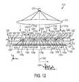
- the one or more second detection regionsmay overlap with the plurality of first excitation regions. If desired, this technique can be used to differentiate, for example, fluorescence tags having different lifetimes. One embodiment utilizing this technique is described below in connection with FIGS. 12 and 13 .
- the frequency analysise.g. FFT
- the devicecan distinguish between fluorescent tags having different lifetimes. In some cases, this technique can also be used to study simultaneously both tag fluorescence and native fluorescence from a particle of interest.
- the spatial filtermay be configured such that the first excitation regions are substantially fully shielded from the detector by the spatial filter.
- the detectormay be a first detector and the spatial filter may be a first spatial filter, and the first excitation light may also be also adapted to stimulate a second light emission from particles of a second particle type, the second light emission having a characteristic second response time ⁇ 2 .
- the apparatusmay in such cases further include a second detector, different from the first detector, and a second spatial filter, different from the first spatial filter.
- the second detectormay be disposed to receive light from a plurality of second detection regions of the flow channel, and may provide a second detector output based on the received light.
- the second spatial filtermay be disposed between the flow channel and the second detector, and may have a second pattern of variable transmission such that (a) the second light emission from a given second particle of the second particle type is transmitted to the second detector if the given second particle is disposed in any of the second detection regions of the flow channel, and (b) the second light emission from the given second particle is at least partially blocked from reaching the second detector if the given second particle is disposed in any of a plurality of second shielded regions of the flow channel, the second shielded regions being interspersed with the second detection regions.
- the second detection regionsmay be spatially separated from the first excitation region(s). Alternatively, the second detection regions may at least partially overlap with, and may substantially coincide with, the first excitation region(s).
- the methodsmay also include providing a detector output of the detector based on light received by the detector, and providing information about the sample based on the detector output.
- the exposingmay occur before the transmitting and the at least partially blocking.
- the transmittingmay be initiated a delay time after an end of the exposing, and the delay time may be short enough so that the transmitted first light emission remains high enough for detection.
- the delay timemay be less than ⁇ 1 .
- the methodmay also be configured to isolate the first light emission from a second light emission emitted by a component in the sample when exposed to the first excitation light, the second light emission being characterized by a second response time ⁇ 2 shorter than ⁇ 1 .
- the delay timemay be tailored to be long enough so that any transmitted second light emission decays to a negligible level to avoid detection.
- the delay timemay be greater than ⁇ 2 .
- fluorescence for the unwanted componentmay have an intensity, after the delay time, of less than about 37% of its initial intensity; desirably, such intensity would be close to 0% of its initial intensity.
- the transmittingmay occur over a time period that is short enough so that the transmitted first light emission remains high enough for detection. For example, if the time period begins when the transmitting begins and ends when the transmitting ends, and the time period may be less than 2* ⁇ 1 .
- fluorescence for a particle of interestmay have an intensity, at the end of the transmitting time period, greater than about 14% (or, for example, greater than about 10%) of its initial intensity at the beginning of such time period; desirably, such intensity would be substantially greater than 10% or 14% of its initial intensity, e.g., in a range of 30-50% or more.
- the one or more first excitation regionsmay include a plurality of first excitation regions, and for the given first particle, the exposing may then be interspersed with the transmitting and the at least partially blocking.
- the transmittingmay in some cases further include transmitting the first light emission from the given first particle when the given first particle is disposed in any of one or more second detection regions of the flow channel.
- the second detection regionsmay be interspersed with the first detection regions and the first shielded regions, and the one or more second detection regions may overlap with the plurality of first excitation regions.
- the excitation lightmay also be effective to stimulate a second light emission from particles of a second particle type in the sample.
- the methodmay then further include: transmitting the second light emission from a given second particle of the second particle type to a second detector when the given second particle is disposed in any of a plurality of second detection regions of the flow channel; and at least partially blocking the second light emission from the given second particle from reaching the second detector when the given second particle is disposed in any of a plurality of second shielded regions of the flow channel, the second shielded regions being interspersed with the second detection regions.
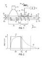
- FIG. 1is a schematic side or sectional view of a sample analyzer
- FIG. 2is a graph of idealized functions of intensity versus time or position for different particle types that may be present in the analyzer of FIG. 1 ;
- FIG. 3is a graph of idealized functions having different decay times, to assist the reader's understanding of the disclosed techniques
- FIG. 4is a graph of an idealized detector output associated with a detection event of a first particle using an analyzer similar to that of FIG. 1 ;
- FIG. 5is a schematic plan or front view of a spatial filter for use in the disclosed analyzers
- FIG. 6is a schematic plan or front view of a spatial filter that is or comprises a color mask or filter assembly that is a combination of a first periodic subpattern of spatially separated first transmitting regions and a second periodic subpattern of spatially separated second transmitting regions, the first and second subpatterns being overlapping, and portions of first transmitting regions overlapping with portions of second transmitting regions, where an offset is shown between the first and second subpatterns along the y-direction for ease of explanation;
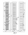
- FIG. 7is a schematic plan or front view of a spatial filter that is or comprises a color mask or filter assembly suitable for use in the disclosed devices, the color mask comprising a combination of a first periodic subpattern of spatially separated first transmitting regions (also shown in the figure) and a second periodic subpattern of spatially separated second transmitting regions (also shown in the figure), the first and second subpatterns being overlapping, and portions of first transmitting regions overlapping with portions of second transmitting regions;
- FIG. 8is a schematic side or sectional view of another sample analyzer that illustrates the use of two independent detector/spatial filter combinations, the analyzer also illustrating both remote sensing and local sensing;
- FIG. 9is a schematic side or sectional view of another sample analyzer, illustrating repetitive, interspersed excitation and detection
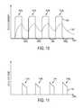
- FIG. 10is a graph of idealized functions of intensity versus time or position for different particle types that may be present in the analyzer of FIG. 9 ;
- FIG. 11is a graph of an idealized detector output associated with a detection event of a first particle using an analyzer similar to that of FIG. 9 ;
- FIG. 12is a schematic side or sectional view of another sample analyzer, illustrating repetitive, interspersed excitation and detection, and also illustrating second detection regions that overlap with excitation regions;
- FIG. 13is a graph of an idealized detector output associated with a detection event of a first particle and a second particle using an analyzer similar to that of FIG. 12 ;
- FIG. 14is a schematic side or sectional view of another sample analyzer, illustrating repetitive, interspersed excitation and detection, and also illustrating two independent detector/spatial filter combinations, and also illustrating second detection regions that overlap with, and that may coincide with, excitation regions;
- FIG. 15is a flow diagram depicting a method that may be carried out with the disclosed analyzers
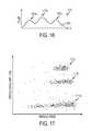
- FIG. 16is a graph containing hypothetical data that may be obtained using the disclosed analyzers and methods.
- FIG. 17is a velocity profile graph that plots particle signal amplitude versus particle speed, the graph containing hypothetical data.
- the size of the excitation areais restricted approximately to the size of the particle to be detected.
- the techniques disclosed hereinmay use a much larger excitation region to increase the total flux of detected light that emanates from a particle of interest.
- spatial filteringcan be employed to enable a high spatial resolution in the micron range. This may allow for independently detecting and characterizing particles with a separation (in the flow direction) that can approach the dimension of individual particles.
- the disclosed techniquescan be intrinsically tolerant to background fluorescence originating from fluorescent components in solution, fluorescent components of the detection apparatus, and surface contaminants.
- FIG. 1An illustrative sample analyzer 110 is shown schematically in FIG. 1 , in the context of a Cartesian x-y-z coordinate system for reference purposes.
- the analyzerincludes a light source 112 , a fluid handling device 120 , a spatial filter 126 , and a detector 130 .
- the fluidic device 120is adapted to receive a sample of interest to be analyzed.
- the samplemay enter the device 120 at an inlet 121 a thereof and exit the device 120 at an outlet 121 b thereof, flowing generally along the x-direction through a flow channel 123 formed between confining members 122 , 124 .
- the members 122 , 124may be or comprise plates or sheets of glass, plastic, or other suitable materials.
- members 122 , 124may be a microscope slide or a microscope cover glass, or portion thereof.
- the members 122 , 124need not, however, be planar in shape. For example, they may be portions of a unitary tube or pipe of circular cross section. Other non-planar shapes are also contemplated. In some cases, confinement of the sample may not be necessary, whereupon one or both of members 122 , 124 may be omitted.
- At least a portion of the confining member 122is transmissive to excitation light emitted by the light source 112 .
- light source 112may emit excitation light in a light beam 112 a towards the fluidic device 120 .
- the excitation lightmay comprise light of a first wavelength ⁇ 1 ; in some cases, the excitation light may have a peak output at the wavelength ⁇ 1 .
- the light source 112may comprise a conventional light emitting diode (LED) source or a resonant cavity LED (RC-LED) source, which may emit light in a bandwidth (measured in terms of full width at half maximum, or FWHM) of 5 to 60 nm, for example.
- the light sourcemay incorporate one or more filters to narrow or otherwise tailor the spectrum of the resultant output light.
- the spectral makeup or composition of the excitation light emitted by the source 112is preferably tailored to excite at least particles of a first type that may be present in the sample, as discussed further below.
- the confining member 122transmits the light beam 112 a such that it illuminates the sample disposed within the flow channel 123 . Illumination of the sample by the light beam 112 a is limited, whether by shaping the beam 112 a with suitable lenses or other optical components, and/or by masking the beam 112 a with a suitable aperture or mask, to a first excitation portion or region 120 a of the flow channel 123 .
- the excitation portion 120 ais a single unitary excitation region of the flow channel 123 , with substantially no other portions or regions of the channel 123 being illuminated by the light source 112 .
- the sampleis depicted as containing two types of particles: first particles 105 , and second particles 106 .
- the first particles 105are assumed to be particles whose presence in the sample is sought to be detected and quantified by the analyzer 110 .
- the second particles 106are assumed to be particles or any other component of the sample that, in the case of FIG. 1 , is not of interest, the presence of which is not sought to be detected or quantified by the analyzer 110 .
- the second particlesmay be or comprise a sub-volume of the carrier fluid that exhibits autofluorescence.
- the “first particle” and “second particle”may represent different portions of a single physical body, e.g., the first particle may represent a tagged portion of a single cell and the second particle may represent a different portion of that same cell.
- the analyzermay be designed to detect and quantify the presence of the second particles also, or of other particles.
- the light 108 emitted by the second particles 106might ordinarily interfere with the detection of light 107 emitted by the first particles.
- the light 108might for example constitute relatively strong autofluorescence arising from second particles 106 or from any other component of the sample, while the light 107 might constitute a weaker fluorescent emission from first particles such as cells that are tagged with a particular fluorescent dye.
- particles of interestwill be understood by the reader to refer broadly to an object of interest to be detected. In most applications, particles of interest are relatively small, and may be microscopic in size.
- a given particle of interestmay be or include one or a collection of biological cell(s), virus(es), molecule(s), sub-molecular complex(es), bead(s) (including microbeads), droplets (e.g. oil in water), gas bubbles, or other bit(s) of matter, for example.
- Cells or other particlesmay be treated, e.g., stained or tagged with a suitable fluorescent probe or other agent, in such a way that they emit light in a predictable fashion when illuminated with excitation light.
- the light emitted by a given excited particlemay be fluorescent in nature, or it may constitute a form of scattered light such as in the case of Raman scattering.
- incident lightthat is effective to excite a particle
- incident excitation lightmay be selectively absorbed by the particle so as to cause the particle to fluoresce, or such incident excitation light may selectively interact in some other way with the particle, e.g. so as to cause resonant Raman scattering.
- the emitted lightis preferably shifted in wavelength to some extent relative to the excitation light so that at least a portion of the emitted light can be at least partially isolated from the excitation light with one or more suitable emission filters.
- the light 108 emitted by the second particleshas at least one characteristic that differs from that of the light 107 emitted by the first particles, and the analyzer 110 is designed to exploit that difference.
- the characteristic response times of light 107 , 108are different. More specifically, we assume that light 107 has a characteristic first response time ⁇ 1 , and that light 108 has a characteristic second response time ⁇ 2 , and that the first response time is greater than (i.e., longer than, or slower than) the second response time: ⁇ 1 > ⁇ 2 .
- the characteristic response time of a given type of emanating lightis a measure of how fast the emanating light decays after the excitation is lowered. For example, if the excitation light were suddenly turned off, the emanating light may decay exponentially with time t in substantial accordance with the function e ⁇ t/ ⁇ , where ⁇ is the characteristic response time of the emanating light.
- the light 107may differ from the light 108 in other ways also.
- the light 107may have spectral characteristics that differ from those of light 108 .
- the light 107may, for example, occur in a first spectral band and the light 108 may occur in a different second spectral band.
- the spectral characteristics of light 107 , 108may have little or no differences, so that such an optical filter may not be usable.
- the excitation light 112 ais depicted as exciting both the first particles 105 and the second particles 106 residing in the excitation region 120 a , causing such excited particles to emanate light 107 , 108 respectively in response to the excitation.
- This light emissionis shown as occurring in the excitation region 120 a .
- the particlesare being carried by the sample through the channel 123 , generally from left to right from the perspective of FIG. 1 . As each particle travels in this fashion, it eventually exits the region 120 a of the flow channel and enters an adjacent gap region before entering a series of detection regions located generally in a detection zone 120 b in FIG. 1 .
- each excited particlecrosses the boundary separating the excitation region 120 a from the gap region, it experiences an abrupt step change in excitation. More particularly, the excited particle goes from being fully illuminated with excitation light 112 a in region 120 a to being exposed to little or no excitation light in the gap region. Therefore, the amount of light emanating from an excited particle begins to decay as a function of time and position in the gap region.
- the gap regionmay be considered to extend from the downstream boundary of the excitation region 120 a to the upstream boundary of the first detection region in the detection zone 120 b , as explained further below.
- the gap regionmay be defined by a suitably sized opaque film or coating on the confining member 122 , or by any other suitable obstruction, or simply by shaping the beam 112 a so as to avoid illuminating the gap region.
- the gap regionis preferably sized to have a longitudinal dimension “g” along the direction of flow, i.e., along the x-axis as shown in FIG. 1 . As a given excited particle traverses this distance g, light emanating from the particle decreases or decays.
- the intensity or flux of light emitted by the particledecays from a relative value of 1 (or 100%) at the beginning of the gap region to a relative value of e ⁇ (g/(s* ⁇ )) at the end of the gap region.
- the analyzer 110and in particular the longitudinal dimension g of the gap region, so that light emanating from the second particles has a negligible intensity or flux, and light emanating from the first particles has a significant intensity or flux, at the time such particles enter the detection zone 120 b.
- the sample and its constituent particles and other componentsmay flow through the channel 123 over some finite range of operational speeds during operation of the analyzer, e.g., between the limits of a minimum speed smin and a maximum speed smax.
- the fluorescence from even a fast-moving unwanted componentmay have an intensity, when entering the detection area, of less than 37% of its initial intensity; desirably, g>2* ⁇ 2 *smax, so that such intensity would be less than 14% of its initial intensity, or more desirably, g>4.5* ⁇ 2 *smax, so that such intensity would be less than 1% of its initial intensity.
- the tag fluorescence for a slow-moving particle of interestmay have an intensity, when entering the detection area, of greater than 37% of its initial intensity; desirably, g ⁇ 0.5* ⁇ 1 *smin, so that such intensity would be greater than 61% of its initial intensity, or more desirably, g is even less, so that such intensity would be close to 100% of its initial intensity.
- the particlesUpon exiting the gap region, the particles enter the detection zone 120 b of the flow channel 123 .
- this zonelight emanating from excited particles is alternately transmitted to a photosensitive detector 130 and (at least partially) blocked from being transmitted to such detector, the alternating transmitting and blocking taking place as a result of a spatial filter 126 being placed between the detector 130 and the flow channel 123 .
- the spatial filter 126is configured with a pattern of variable transmission, such as a plurality of transmitting portions 126 a and a plurality of shielding portions 126 b .
- an excited particlepasses through the detection zone 120 b of the flow channel 123 , it passes through detection regions, in which emanating light is transmitted through a given one of the transmitting portions 126 a to the detector 130 , and it passes through shielded regions, in which emanating light is at least partially blocked from the detector 130 by a given one of the shielding portions 126 b .
- the alternating transmitting and blocking of the emanating lightproduces a time variation in the detector output 132 .
- An exemplary (idealized) time-varying output signal 134is shown in FIG. 1 .
- a signal processing unit 140can be used to evaluate the detector output signal, and provide a measure of at least the first particles in the sample based on the evaluation.
- the intensity or flux of the excited particle's emanating lightis also monotonically decreasing in accordance with such particle's characteristic response time ⁇ .
- the analyzer 110is designed such that light emanating from an excited particle that we wish to measure, such as a “first particle”, remains at detectable levels throughout the detection zone 120 b , even at the slowest operation flow speed (smin) of the analyzer.
- the tag fluorescence for a slow-moving particle of interestmay have an intensity, when exiting the final one of the first detection regions, greater than about 14% (or, for example, greater than about 10%) of its initial intensity when it entered the initial one of the first detection regions; desirably, such intensity would be substantially greater than 10% or 14% of its initial intensity, e.g., in a range of 30-50% or more.
- ⁇ 1is the characteristic response time of the light emitted by the first particle
- L 1is the length along the flow channel of the collective set of all first detection regions defined by the spatial filter.
- the tag fluorescence for a slow-moving particle of interestmay have an intensity, when exiting the final one of the first detection regions, greater than about 14% (or, for example, greater than about 10%) of its initial intensity when it entered the initial one of the first detection regions; desirably, such intensity would be substantially greater than 10% or 14% of its initial intensity, e.g., in a range of 30-50% or more.
- L 1we may consider L 1 to also equal the length of the detection zone 120 b as measured along the x-axis, the detection zone extending from the upstream boundary of the detection region located at the upstream end of the spatial filter (which boundary also coincides with the downstream boundary of the gap region) to the downstream boundary of the detection region located at the downstream end of the spatial filter.
- the confining member 122substantially transmits at least the emanating light 107 originating from the various excited first particles in the flow channel.
- the transmitted emanating lightis also then selectively transmitted by the spatial filter 126 as discussed above and intercepted by the photosensitive detector 130 , which converts the intercepted light into a current, voltage, or other measurable parameter.
- the detector 130is a single large area detector that provides only one output, such output varying in time in accordance with the light impinging on the active surface of the detector.
- the detectormay include a plurality or array of distinct photosensitive devices.
- the detectorcollects light emanating from excited particles residing in specific bounded portions, referred to as a detection portions, of the flow channel.
- the detection portions of the flow channelmay be determined or defined as a function of the size and placement of the detector, design details of the flow channel, design details of the spatial filter, and the presence of any lenses, mirrors, masks, apertures, or other optical components not shown in FIG. 1 that may be placed between the detector and the flow channel, and so forth.
- the detection portions of the flow channelare all spatially separated from the excitation region 120 a of the flow channel.
- the detection portionsmay include first detection portions that are spatially separated from the excitation region(s), and second detection portions that at least partially overlap with the excitation region(s).
- Exemplary photosensitive detectorsthat may be used in the disclosed systems, depending on the design specifications of the analyzer, include robust solid-state devices such as conventional photodiodes and avalanche photodiodes (APDs). Silicon photodiodes are responsive over a wavelength range from roughly 300 nm to 1.1 microns, and are plentiful, rugged, reliable, and relatively inexpensive. Numerous other types of photodiodes are also available, such as germanium, indium gallium arsenide (InGaAs), and extended-InGaAs, to name only a few. If desired, any other type of photosensitive detector may also be used, including, for example, one or more photomultiplier tubes.
- IGaAsindium gallium arsenide
- extended-InGaAsextended-InGaAs
- the detectormay be of hybrid design, and in that regard may include one or more preamplifiers, thermoelectric coolers, and/or other features or capabilities.
- the detector 130may have an inherent responsivity that makes it responsive both to light 107 emanating from first particles 105 and to light 108 emanating from second particles 106 , such that the detector does not have any ability to inherently distinguish between such emanating light. For this reason, some or all of the detection regions are spatially separated from the excitation region(s) as discussed elsewhere herein in order to remove or reduce the contribution of light emanating from the second particles on the detector output, or in some cases, to allow the signal processing unit to distinguish between light emanating from the second particles from light emanating from the first particles.
- an optical emission filter(not shown in FIG. 1 ) between the detector 130 and the flow channel.
- the emission filterpreferentially blocks, e.g. by reflection, absorption, scattering, or any other know mechanism, any stray excitation light from the light source that may otherwise impinge on the photosensitive surface of the detector.
- the emission filterpreferentially transmits light emanating from excited particles in the flow channel, which emanating light is typically at longer wavelengths than the excitation light. In some cases, even stray excitation light may be strong enough to overpower the sometimes weak detector signal produced by particle-emanating light.
- An emission filteris therefore sometimes needed or desired to prevent the detector 130 and/or its amplifier circuit(s) from experiencing saturation, and to allow lower noise detection of the emanating light from the particles.
- Such an optical filtermay of course be incorporated into the analyzer 110 of FIG. 1 , and other analyzers disclosed herein.
- Other techniquescan also be used to minimize the amount of excitation light reaching the detector.
- the excitation light sourcemay be suitably positioned to avoid direct or indirect illumination of the detector by the excitation light beam.
- the optical emission filterif used, may have more relaxed design requirements than would otherwise be needed due to the spatial separation of excitation region(s) and detection regions(s).
- the detectorWhen the detector 130 is used, the detector generates an output on line 132 , which may be supplied to signal processing unit 140 .
- the line 132may be or comprise a coaxial cable, or a twisted pair of wires.
- the line 132carries a time varying output signal, depicted schematically as output 134 .
- the signal processing unit 140may perform an analysis on the output signal 134 .
- the analysismay include, for example, measuring correlation(s) with one or more other signals, and/or evaluating the frequency content of the output signal.
- the results of the analysismay be used to provide one or more measures of at least the first particles 105 in the sample, e.g., absolute or relative amounts of such particles in the sample, particle speeds and speed distributions, particle sizes, and so forth. In some cases, the results of the analysis may also be used to provide similar measures of the second particles 106 in the sample. Reference in this regard is made to, e.g., the analyzer of FIG. 12 , described below.
- the signal processing unit 140may comprise one or more microprocessors and/or microcontrollers, and/or one or more application specific integrated circuits (ASICs), and/or one or more field-programmable gate arrays (FPGAs), and/or any other digital signal processing (DSP) circuitry.
- ASICsapplication specific integrated circuits
- FPGAsfield-programmable gate arrays
- DSPdigital signal processing
- the signal processing unitmay also optionally include volatile and/or non-volatile memory, storage device(s), and software.
- Software, hardware, and/or firmwaremay be tailored to carry out frequency analysis of one or more a time-varying signal, e.g., a set of instructions to carry out a fast Fourier transform (FFT) procedure or other Fourier transform or other transform procedure.
- FFTfast Fourier transform
- the signal processing unitmay be or comprise a desktop, laptop, notebook, or other portable or non-portable computer system, including e.g. mobile phones, smart phones, or any other type of personal digital assistant, suitably equipped with appropriate interfaces, networks, hardware, and software to carry out the desired signal analysis.
- FIG. 2we see there a graph of idealized functions of intensity or flux versus time or position for different particle types that may be present in the sample to be analyzed by the analyzer of FIG. 1 .
- the intensity or flux of the emanating light of each particleis shown for simplicity as a percentage of a maximum value.
- the horizontal axis of the graphmay be interpreted as the time measured from a given event, e.g., the time after which a given particle enters the inlet 121 a , or it may be interpreted as the position x along the flow direction (x-axis in FIG. 1 ) of a given particle.
- Idealized curve 207is intended to be representative of a given first particle, whose characteristic response time ⁇ 1 for emanating light is relatively long, while idealized curve 208 is intended to be representative of a given second particle, whose characteristic response time ⁇ 2 for emanating light is relatively short. That is, ⁇ 2 ⁇ 1 .
- regions 220 a , 220 g , 220 bare meant to correspond to the excitation region 120 a , the gap region, and the detection zone 120 b respectively of the flow channel 123 .
- inspection of curve 208shows that as a given second particle 106 travels along the flow channel 123 and enters the excitation region 120 a , it also becomes excited, and the light it emanates in response to the excitation also increases to a maximum flux or intensity value. See region 220 a of the graph.
- the light emitted by the second particlemay substantially reach its maximum value much faster than that of the first particle, due to the characteristic response time ⁇ 2 being faster than ⁇ 1 .
- the excitation lightis removed or substantially reduced.
- the amount of light emitted by the second particlebegins to decrease or decay in the region 220 g of the graph.
- the second particle 106crosses the boundary from the gap region to the detection zone 120 b of the flow channel 123 , excitation light continues to be substantially absent.
- the amount of light emitted by the second particle(which may still be excited to some extent, or which may no longer be substantially excited) continues to decrease or decay in the region 220 b of the graph, or remains at or near zero through the region 220 b .
- FIG. 3is a graph of idealized functions having different decay times.
- curve 307exponentially decays from a value of 100% to a value of 1/e (about 36.8%) in a time ⁇ 1 .
- Curve 308exponentially decays from a value of 100% to the same value of 1/e in a shorter time ⁇ 2 .
- Curve 307may be representative of light intensity of light emanating from a first excited particle after excitation is removed; curve 308 may be representative of light intensity of light emanating from a second excited particle after excitation is removed.
- FIG. 4is a graph of an idealized detector output 407 associated with a detection event of a first particle using an analyzer similar to that of FIG. 1 .
- the vertical axis of the graphrepresents the detector output. For simplicity, it is shown as a percentage of a maximum value.
- the horizontal axis of the graphmay be interpreted as the time measured from a given event, e.g., the time t 1 may be the moment when a given particle exits the gap region and enters the detection zone, or the horizontal axis may be interpreted as the position x along the flow direction (x-axis in FIG. 1 ) of a given first particle.
- a baseline curve 407 ′is provided to represent the idealized detector output if the spatial filter were entirely omitted, such that none of the light emanating from the excited particle is blocked from reaching the detector in the detection zone. In the absence of the spatial filter, the baseline curve 407 ′ monotonically decays in the same way that curve 307 ( FIG. 3 ) or curve 207 ( FIG. 2 ) decays.
- the spatial filterwhen the spatial filter is included, its pattern of alternating transmitting portions and shielding portions (see e.g. elements 126 a , 126 b respectively in FIG. 1 ) define corresponding detection regions and shielded regions in the flow channel.
- the signal portions 407 a , 407 b , 407 c , 407 d , 407 e , and 407 fcorrespond to five distinct detection regions in the flow channel, and five distinct transmitting portions of the spatial filter. Comparing the width of the signal portions 407 a through 407 f reveals that the five distinct transmitting portions of the spatial filter do not have the same length in the longitudinal direction, assuming the particle moves at a constant speed through the flow channel.
- the detector signalmay be at or near a zero level as the result of the blocking action provided by five distinct shielding portions of the spatial filter. Comparing the width of these portions of the signal 407 reveals that the five distinct shielding portions of the spatial filter do not have the same length in the longitudinal direction, again assuming the particle moves at a constant speed through the flow channel.
- the spatial filtermay be configured to define more or fewer than six distinct detection regions, and more or fewer than five shielded regions, in the flow channel.
- the detection regionsmay all have the same longitudinal dimension, or they may differ from each other.
- the shielded regionslikewise may all have the same longitudinal dimension, or they may differ from each other.
- the pattern of detection regions and shielded regions defined by the spatial filtermay be periodic or non-periodic, as desired.
- FIGS. 5 , 6 , and 7Further considerations regarding possible spatial filter designs are provided in FIGS. 5 , 6 , and 7 .
- the spatial filter 526which may in some cases be a magnified or de-magnified image of a remotely positioned spatial filter as explained below, selectively masks light emanating from particles within the flow channel of a fluid handling device 520 .
- First and second particles 505 , 506are shown to be disposed behind the spatial filter 526 , traveling in a flow direction generally parallel to the x-axis.
- the spatial filter 526comprises transmitting portions 526 a and shielding portions 526 b arranged in a pattern of variable transmission along the longitudinal direction.
- the filtermay be an extended film or layer of opaque material in which a number of apertures have been formed.
- the aperturesmay correspond to the transmitting portions 526 a
- the shielding portions 526 bmay correspond to the undisturbed opaque material.
- the longitudinal dimensions (lengths) of the alternating transmitting portions 526 a and shielding portions 526 bdetermine the transmission function as a function of position along the x-axis.
- the pattern or sequence of transmitting portions 526 a and shielding portions 526 b in the spatial filter 526define a transmission function that changes based on longitudinal position, i.e., based on position measured along the x-direction or flow direction.
- This transmission functionmay be substantially periodic, or it may instead be substantially non-periodic.
- An example of a periodic transmission functionis a square wave, or a rectangle wave of constant period.
- a limitation of periodic transmission functionsis that they do not typically allow for high spatial resolution of a detected particle. However, this limitation may be unimportant in cases of rare event detection, i.e., in cases where the particle density is low enough so that only a single particle (at most) is likely to be present in the detection portion of the flow channel at any given time.
- Examples of thismay include pathogen detection in water, or rare cell scanning.
- the disclosed analyzers and related techniquesare generally well suited for rare event detection.
- Rare event detectionbenefits from large throughput and large detection area, but background scatter or autofluorescence typically increases strongly with detection area, hence resulting in the need to reduce such background relative to the signal of interest to achieve acceptable signal-to-noise levels.
- Another advantage of a periodic transmission functionis its ability to produce a clear, strong peak in the frequency spectrum (e.g. the fast Fourier transform, or FFT) of the detector output signal, for a single particle moving at a constant speed in the detection zone.
- FFTfast Fourier transform
- Non-periodic transmission functionis a random function, or a chirped function (having a monotonically increasing or decreasing period).
- An advantage of non-periodic transmission functionsis that they do typically allow for high spatial resolution of a detected particle, by employing correlation techniques to determine the longitudinal position of the particle at a given moment in time. For example, a correlation may be carried out between the time-varying detector output 134 and a signal template representative of the (non-periodic) transmission function. The presence and location of a peak in the correlation can be used to determine the precise position of the particle along the length of the spatial filter 126 . This capability is not limited to rare event detection, and can be used with higher particle densities in which multiple particles are present in the detection portion of the flow channel at a given time.
- MFSminimum feature size
- the MFSrefers to the length, as measured along the longitudinal direction (i.e., the flow direction, e.g., the x-direction in FIGS. 1 and 5 ), of the shortest identifiable region of the spatial filter.
- the shortest identifiable regionmay in some cases be a transmitting portion, while in other cases it may be a shielding portion, while in still other cases it may be both a transmitting portion and a shielding portion (i.e., if the shortest transmitting portion has the same longitudinal length as the shortest shielding portion, or if all transmitting portions have the same longitudinal length as all shielding portions).
- the MFS of the spatial filter used in an analyzerhas a direct impact on the spatial resolution of the analyzer, with larger MFSs generally corresponding to lower spatial resolutions.
- the average or typical particle sizealso has an impact on spatial resolution.
- the spatial filter 526may be substantially monochromatic, or it may be polychromatic as in the case of a color filter assembly.
- the transmitting portions 526 aall have substantially the same transmission characteristic
- the shielding portions 526 balso all have substantially the same transmission characteristic (but different from that of the transmitting portions).
- the transmitting portions 526 amay all be completely clear, as in the case of an aperture
- the shielding portions 526 bmay be completely opaque, as in the case of a layer of black ink or other absorptive, reflective, or scattering material.
- the transmitting portions 526 amay all have a given color or filter characteristic, e.g., high transmission for light emanating from excited particles, but low transmission for excitation light.
- the shielding portionsmay have a low but non-zero light transmission, as in the case of a grey ink or coating, or a partial absorber or reflector.
- first transmitting portionsmay have a first transmission characteristic
- second transmitting portionsmay have a second transmission characteristic, each of these transmission characteristics being different from the (usually opaque or nearly opaque) transmission characteristic of the shielding portions.
- the first transmission characteristicmay correspond to a first filter type
- the second transmission characteristicmay correspond to a second filter type.
- the polychromatic spatial filtermay be used in analyzers designed to detect not only a first particle type, which may emit light in a first spectral band, but also a third particle type, which may emit light in a different third spectral band.
- first and third particleshave relatively long characteristic response times ⁇ 1 , ⁇ 3 , in comparison to the second particle type which may emit light having a much shorter characteristic response time ⁇ 2 .
- the physical separation of the detection regions from the excitation region(s)may then be used to remove the effect of any excited second particles on the detector output, while allowing both light emanating from first particles, and light emanating from third particles, to produce time-variation in the detector output signal.
- the different layouts or arrangements of first filter types and second filter typescan then be used to ensure that the time variation in the detector output for light emanating from the first particle type is different from the time variation in the detector output for light emanating from the third particle type.
- a temporal or frequency-based analysis of the time-varying detector outputcan then distinguish the detection of a first particle from that of a third particle.
- the first and second filter types used in the polychromatic filterare tailored to preferentially transmit emanating light from the first and third particle types, respectively.
- first transmitting portions of the polychromatic spatial filtermay have a higher transmission for red light than for green light, e.g., they may transmit red light and substantially block green light
- second transmitting portions of the polychromatic spatial filtermay have a higher transmission for green light than for red light, e.g., they may transmit green light and substantially block red light.
- the first transmitting portionscan be arranged in a periodic fashion with a first spacing or periodicity
- the second transmitting portionscan be arranged in a periodic fashion with a different second spacing or periodicity.
- the different spacings or periodicities provided by the sets of different transmitting portionstogether with the fact that the transmission characteristics of these regions are tailored to selectively transmit emanating light from a particular type of particle, can be used to provide two distinct mask frequencies f m1 , f m2 in the frequency spectrum of the detector output signal for the different first and third particles, assuming such particles are traveling at a particular (same) speed.
- FIG. 6we see a top view of a color mask or filter assembly 609 that includes a plurality of first filter regions (A) and a plurality of second filter regions (B).
- the filter assembly 609may include only 5 first regions (A) and 7 second regions (B), as shown, or it may include more or fewer than 5 first regions and/or more or fewer than 7 second regions, as desired.
- the first regions (A)are arranged to form a first subpattern of the overall pattern of filter regions, and the second regions (B) are arranged to form a second subpattern.
- the first filter regionsare displaced slightly along the transverse y-axis relative to the second filter regions so that the two different regions can be more clearly identified in the figure, but such transverse displacement may be omitted in practical embodiments.
- the first subpatternis characterized by a uniform center-to-center spacing SA between neighboring first filter regions (A), and the second subpattern is characterized by a different uniform center-to-center spacing SB between neighboring second filter regions (B).
- the different spacingsprovide the subpatterns with different dominant spatial frequencies, which in turn can be used to ensure that the time-varying detector signals associated with different particle types have different temporal frequency content.
- the subpatterns in the filter assembly 609overlap in such a way that at least one first filter region (A) overlaps at least one second filter region (B).
- the overlap of the filter regions referred to heredoes not refer to the simple effect that can be observed by physically laying one band pass filter atop a different one. Such physical overlap is a subtractive process, whereas the overlap referred to in FIG. 6 is an additive process.
- a band pass filter that transmits only green lightis physically laid atop a band pass filter that transmits only red light, the result is typically an opaque region because any red light transmitted by the red filter is blocked by the green filter, and any green light transmitted by the green filter is blocked by the red filter.
- the overlap regionhas a broader range of transmission wavelengths than either of the first and second filter regions individually.
- the resultis a yellow filter region, which transmits both green light and red light but blocks blue light.
- the yellow filter regionwith its broader transmission range, would typically be formed by applying a distinct yellow-transmitting material on the overlap region of a transparent substrate, and would not be formed by applying separate layers of a green-transmitting material and a red-transmitting material on the overlap region.
- a desired spatial periodicity of the first filter regionscan be preserved, and the desired spatial periodicity of the second filter regions can also be preserved.
- the overlap of the subpatternsresults in four distinct types of light transmitting or blocking areas: area 610 , which represents regions of (additive-type) overlap between first filter region (A) and second filter region (B); area 612 , which represents the first filter region (A) only; area 614 , which represents opaque regions; and area 616 , which represents the second filter region (B) only.
- area 610which represents regions of (additive-type) overlap between first filter region (A) and second filter region (B)
- area 612which represents the first filter region (A) only
- area 614which represents opaque regions
- area 616which represents the second filter region (B) only.
- Each of these areasrepeats along the longitudinal direction in accordance with the particular arrangement of first and second filter regions depicted in FIG. 6 .
- FIG. 7is a top view of another color mask or filter assembly 709 suitable for use in the disclosed devices, the filter assembly 709 comprising a combination (an additive combination) of a first periodic subpattern 709 A of first filter regions A, and a second periodic subpattern 709 B of second filter regions B.
- the filter assembly 709is similar to filter assembly 609 ( FIG. 6 ) discussed above, insofar as both the subpatterns, and individual filter regions of different types, are overlapping.
- the first subpattern 709 Aof longitudinal dimension LA, comprises a periodic array of first filter regions A, which are formed as apertures in a generally rectangular opaque region 711 A.
- the first filter regionshave a uniform center-to-center spacing of SA.
- the second subpattern 709 B, of longitudinal dimension LBcomprises a periodic array of second filter regions B, which are formed as apertures in a generally rectangular opaque region 711 B.
- the second filter regionshave a uniform center-to-center spacing of SB.
- the filter assembly 709results.
- Any suitable band pass or transmission characteristicsmay be used for the first and second filter regions A, B, but for simplicity of description we will assume that the first filter regions (A) transmit green light, and the second filter regions (B) transmit red light. In that case:
- the uniform spatial periodicity for green light (center-to-center spacing SA) from subpattern 709 A, and the different uniform spatial periodicity for red light (center-to-center spacing SB) from subpattern 709 B,is preserved.
- the polychromatic spatial filter or filter assembly 709can be used in the analyzer of FIG.
- first particleswhose emanating light has a long characteristic response time ⁇ 1 and is substantially transmitted by the first filter regions A (and at least partially blocked by the second filter regions B), and third particles, whose emanating light also has a long characteristic response time ⁇ 3 and is substantially transmitted by the second filter regions B (and at least partially blocked by the first filter regions A), while avoiding interfering effects of second particles, whose emanating light has a relatively short characteristic response time ⁇ 2 , even in cases where the emanating light from the second particles would be highly transmitted by the first filter regions A and/or the second filter regions B.
- a detector signal caused by the detection event of the first particlewould exhibit a variability having a first dominant frequency (associated with the spacing SA of the first filter regions A), and a detector signal caused by the detection event of the third particle would exhibit a variability having a different third dominant frequency (associated with the spacing SB of the second filter regions B), the third dominant frequency being faster or higher than the first dominant frequency since we assume for this embodiment SB ⁇ SA.
- patterned color maskscan be utilized in the disclosed analyzers to differentiate signals from objects tagged with long lifetime tags having different spectral emission properties, e.g., different colors or wavelength bands.
- the tagsmay also have characteristic response times that are both relatively long but different from each other.
- the different lifetimesproduce different time-varying signal shapes, which can be used by the analyzer as additional differentiation criteria.
- FIG. 8shows schematically another sample analyzer 810 that illustrates the use of two independent detector/spatial filter combinations, the analyzer 810 also illustrating both remote sensing and local sensing.
- This analyzer, and the other analyzers described herein,may be or comprise a POC flow cytometer.
- the analyzer 810includes a fluidic device 820 which may be a fluidic chip.
- the fluidic deviceis adapted to receive the sample of interest to be tested, and to cause the sample to flow through a flow channel 823 formed between confining members 822 , 824 .
- a syringe, pump, or other suitable devicemay be used to provide such sample flow.
- the samplemay include first particles 805 and second particles 806 having different characteristics as discussed elsewhere herein.
- a light source 812is coupled to interface 822 a of the confining member 822 , the interface being an angled surface of the confining member 822 to allow excitation light from the light source to propagate within the confining member 822 and illuminate a bounded excitation region 820 a of the flow channel 823 .
- the light source 812may emit excitation light 812 a that is centered at or peaks at a first wavelength ⁇ 1 , and the confining member 822 is substantially transmissive to at least the wavelength ⁇ 1 .
- the light source 812is preferably a solid state device such as a laser diode or LED.
- the excitation light 812 ais effective to excite light emission from the first particles 805 and from the second particles 806 in the excitation region 820 a .
- One or more lenses, mirrors, apertures, and/or other optical elementsmay be used to ensure the excitation region is substantially bounded.
- a gap regionseparates the excitation region 820 a of the flow channel 823 from a detection zone 820 b of the flow channel 823 .
- the detection zoneis composed of a number of detection regions interspersed with shielded regions as will be described shortly.
- the gap regionis preferably configured to have a longitudinal dimension sufficient to allow light emanating from the second particles 806 to substantially decay to a small or negligible level by the time such second particles enter the detection zone 820 b , even if the second particles travel at a maximum operational flow speed smax through the flow channel.
- the longitudinal dimension of the gap regionis also preferably short enough so that light emanating from the first particles 805 remains relatively high at the time such first particles enter the detection zone 820 b , even if the first particles travel at a minimum operational flow speed smin through the flow channel.
- the length of the detection zone 820 bis also preferably short enough so that light emanating from the first particles 805 remains relatively high over substantially the entire length of the detection zone 820 b , even if the first particles travel at the minimum operational flow speed smin.
- At least some of the light emanating from at least the excited first particlesis detected by one or both of photosensitive detectors 830 , 832 .
- Each of these detectorsmay have its own spatial filter associated with it in order to derive more information from the excited particles.
- a first spatial filter 826is disposed at the detector 830 .
- a working portion 826 a of the filter 826characterized by a sequence of transmitting and shielding portions arranged along the longitudinal direction, is imaged by an optical element 827 such as one or more suitable lenses and/or mirrors onto the detection zone 826 b of the flow channel 823 .
- the optical element 827may provide magnification, in which case the detection zone 826 b may be smaller or larger than the working portion 826 a .
- the detector 830 and the spatial filter 826are both remotely disposed relative to the fluidic device 820 .
- the remote configurationcan allow for more convenient repair or replacement of the remotely-located parts, e.g., the detector 830 and/or the spatial filter 826 .
- the spatial filter 826may be removeably mounted to allow for replacement with a different spatial filter having a different pattern of transmitting and shielding portions.
- the detector 832and its associated spatial filter 828 , are not remotely configured but are instead disposed locally, i.e., at or on the fluidic device 820 .
- This local configurationcan allow for a more compact and simpler design than a remote configuration.
- the spatial filter 828has a working portion 828 a , which is disposed at or on the confining member 824 at an edge or boundary of the flow channel 823 .
- the working portion 828 aalso corresponds to a second detection zone of the flow channel 823 for purposes of detector 832 .
- the second detection zoneis the same as the detection zone 820 b , but this need not be the case in general.
- the portion 826 b and the portion 828 amay likewise be of the same or nominally the same size.
- Each of the detectors 830 , 832provides its own detector output which varies in time in accordance with at least: the passage of excited particles through the detection zone 820 b of the flow channel 823 ; and the pattern of transmitting and shielding portions of the respective spatial filter. Each of these detector outputs may then be evaluated and analyzed independently of each other using the various signal analysis techniques discussed herein.
- Optical emission filters 831 , 833may be provided for the respective detectors 830 , 832 in order to block at least any residual excitation light that would otherwise fall on the detectors, while transmitting light emanating from at least one of the particle types.
- the analyzer 810may be configured in numerous different ways. In one simple approach, both detector channels may be configured to detect the same first particles in the sample. This may be done for purposes of redundancy, increased signal-to-noise, or for other reasons. In this simple approach, the filters 831 , 833 may each transmit emanating light from the first particles and block excitation light, such that the outputs of each detector 830 , 832 contain signal contributions from the first particles 805 .
- the spatial filters 826 , 828may each be monochromatic. Other design details of spatial filters 826 , 828 may the same, or different.
- the spatial filters 826 , 828may both have periodic transmission functions, or they may both have non-periodic transmission functions, or one may have a periodic transmission function and the other may have a non-periodic transmission function. Even if the spatial filters 826 , 828 have the same type of transmission function, e.g., periodic, the design details may be different—the transmission function of one of the spatial filters may have a relatively short spatial period, while that of the other spatial filter may have a longer spatial period. If the transmission functions of both of the spatial filters are non-periodic, the non-periodic transmission functions may likewise be the same, or very different.
- the analyzer 810may be configured so that one detector channel, e.g. the detector 830 /spatial filter 826 combination, detects the first particles, while the other detector channel, e.g. the detector 832 /spatial filter 828 combination, detects third particles, where the third particles have an associated characteristic response time ⁇ 3 of roughly the same order as ⁇ 1 , or at least where ⁇ 2 ⁇ 3 , and where light emanating from the third particles can be spectrally separated (at least in part) from the light emanating from the first particles using one or more suitable optical filters.
- one detector channele.g. the detector 830 /spatial filter 826 combination
- the other detector channele.g. the detector 832 /spatial filter 828 combination
- the third particleshave an associated characteristic response time ⁇ 3 of roughly the same order as ⁇ 1 , or at least where ⁇ 2 ⁇ 3 , and where light emanating from the third particles can be spectrally separated (at least in part) from the light emanat
- the spatial separation of the detection zone 820 b from the excitation region 820 ais effective to suppress detection of the second particles, or to suppress interference from light emanating from the second particles.
- optical filteringmay be employed.
- filter 831may block light emanating from the third particles and block excitation light, but transmit light emanating from the first particles 805
- the filter 833may block light emanating from the first particles 805 and block excitation light, but transmit light emanating from the third particles.
- the spatial filters 826 , 828may each be monochromatic, and other design details of the spatial filters may the same, or different.
- the spatial filters 826 , 828may both have periodic transmission functions, or they may both have non-periodic transmission functions, or one may have a periodic transmission function and the other may have a non-periodic transmission function.
- the analyzer 810may be configured so that one or both of the detector channels detects at least two different particle types.
- the detector channel comprising the detector 830 /spatial filter 826 combinationmay be configured to detect both first particles and third particles, where again the third particles are assumed to have an associated characteristic response time ⁇ 3 of roughly the same order as ⁇ , or at least where ⁇ 2 ⁇ 3 , and where light emanating from the third particles can be spectrally separated (at least in part) from the light emanating from the first particles using one or more suitable optical filters.
- spatial filter 826may be or comprise a polychromatic spatial filter such as those described in connection with FIGS. 6 and 7 .
- the different filter types used in such spatial filter 826may then be chosen to selectively transmit light emanating from first particles and light emanating from third particles, such different filter types being arranged such that the spatial filter 826 effectively provides different transmission functions for light emanating from the first particles compared to light emanating from the third particles.
- the emission filter 831if included, preferably transmits light emanating from first particles and light emanating from third particles, but blocks excitation light.
- the different transmission functionsmay have different spatial frequencies, which produce different temporal frequencies in the time-varying detector output depending on whether an excited first particle or an excited third particle is traveling through the detection zone of the flow channel 823 at a given speed.
- the other detector channele.g., the detector channel comprising the detector 832 /spatial filter 828 combination
- the detector channelmay be configured to detect: the first particles only, or the third particles only, or both the first particles and the third particles, or a different type of particle only (e.g. a fourth type of particle only, where fourth particles are assumed to have an associated characteristic response time ⁇ 4 of roughly the same order as ⁇ 1 and/or ⁇ 3 , or at least where ⁇ 2 ⁇ 4 , and where light emanating from the fourth particles may be spectrally separated (at least in part) from the light emanating from the first and third particles using one or more suitable optical filters), or other combinations of particle types.
- the spatial filter 828may be monochromatic or polychromatic, and it may be periodic or non-periodic as desired.
- one or more excitation light sourcesmay be provided in addition to light source 812 .
- another light sourcewhose wavelength and/or other output characteristics are suitable to excite the additional particle(s) to be detected
- the additional light sourcemay be configured to illuminate the same excitation region 820 a , or one or more different excitation region(s) of the flow channel 823 .
- one of the particle types to be detectedmay have a substantially different characteristic response time compared to another particle type to be detected. For example, if a first and third particle type are to be detected, and a second particle type is to be suppressed (and not of interest), the characteristic response times of the first, second, and third particle types may satisfy the condition ⁇ 2 ⁇ 3 ⁇ 1 .
- a first detector channelmay be configured to measure the first particles
- a second detector channelmay be configured to measure the third particles.
- the spatial filter and detector for the first detector channelpreferably defines a detection zone that is substantially longer in the longitudinal direction, to accommodate the longer response time ⁇ 1 , than the detection zone for the second detector channel, which is sized to accommodate the shorter response time ⁇ 3 .
- analyzer 810may be modified to provide: a remote detector 832 but a local spatial filter 828 ; a remote detector 832 and a remote spatial filter 828 ; a remote detector 830 but a local spatial filter 826 ; and a local detector 830 and a local spatial filter 826 .
- the spatial filter 826may have substantially the same arrangement or pattern of transmitting and shielding portions as spatial filter 828 . In other cases, the patterns for these filters may be different.
- One spatial filtermay have a periodic pattern, while the other spatial filter may have a non-periodic pattern.
- one spatial filtermay have a first periodic pattern, and the other spatial filter may have a second periodic pattern different from the first pattern.
- one spatial filtermay have a first non-periodic pattern, and the other spatial filter may have a second non-periodic pattern different from the first pattern.
- One spatial filtermay have a monochromatic pattern, while the other spatial filter may have a polychromatic pattern.
- both spatial filtersmay have monochromatic patterns, or both may have polychromatic patterns.
- the detectors 830 , 832may have substantially the same detector characteristics, or they may be different.
- the detectors 830 , 832may both be silicon photodiodes, or they may be photodiodes made of some other detector material, and they may thus have substantially the same spectral responsivity.
- the detectors 830 , 832may be composed of different detector materials (e.g., different semiconductors), and they may thus have substantially different spectral responsivities.
- the analyzer 810may be made in a relatively small format suitable for use in POC applications.
- the thicknesses of elements 822 , 823 , and 824 in FIG. 13may be 2 mm, 25 microns, and 75 to 100 microns, respectively, but these dimensions should not be construed to be limiting.
- Other details regarding suitable analyzer featuresmay be found in Patent Application Publication US 2010/0201988 (Kiesel et al.).
- FIG. 8the concept shown in FIG. 8 of using two different detector/spatial filter combinations can be extended in a straightforward fashion to more than two such combinations.
- three, four, or more different detectors and/or detector/spatial filter combinationsmay be used for a given flow channel and analyzer.
- two, three, or more laser diodes or other excitation sourcesmay be arranged to illuminate substantially the same excitation region 820 a , or to illuminate different excitation regions, for example, by arranging such sources in a ring geometry.
- Such conceptscan also be applied to the other analyzers disclosed herein.
- FIG. 9we see there a schematic view of another sample analyzer 910 .
- the analyzer 910utilizes repetitive, interspersed excitation and detection regions.
- the readeris cautioned that features discussed in connection with any of the embodiments herein should be understood as also applying (at least as optional features or modifications) to all other disclosed embodiments, unless otherwise indicated.
- the analyzer 910therefore incorporates a light source 912 , a fluid handling device 920 , a first spatial filter 926 , and a detector 930 .
- the analyzer 910also includes a second spatial filter 928 , which is used in combination with the light source 912 so as to define a plurality of distinct excitation regions of the flow channel, just as the first spatial filter 926 is used in combination with the detector 930 to define a plurality of distinct detection regions of the flow channel.
- the fluidic device 920is adapted to receive a sample of interest to be analyzed.
- the samplemay enter the device 920 at an inlet 921 a thereof and exit the device 920 at an outlet 921 b thereof, flowing generally along the x-direction through a flow channel 923 formed between confining members 922 , 924 .
- the members 922 , 924may be the same as or similar to other confining members discussed herein.
- the light source 912may be the same as or similar to other excitation light sources discussed herein.
- the light source 912thus preferably emits excitation light in a light beam 912 a towards the fluidic device 920 .
- an optical element 913such as one or more suitable lenses and/or mirrors may be used with or included in the light source.
- the excitation light 912 amay comprise light of a first wavelength ⁇ 1 , and in some cases, the excitation light may have a peak output at the wavelength ⁇ 1 .
- the spectral makeup or composition of the excitation light emitted by the source 912is preferably tailored to excite at least particles of a first type that may be present in the sample.
- the confining member 922transmits the light beam 912 a such that it illuminates the sample disposed within the flow channel 923 .
- the second spatial filter 928is interposed between the light source 912 and the flow channel 923 , and its pattern of variable transmission operates to allow the light beam 912 a to illuminate only selected portions, referred to as excitation regions, of the flow channel 923 .
- the spatial filter 928is depicted as having transmitting portions 928 a , 928 c , 928 e , and 928 g arranged in alternating fashion with shielding portions 928 b , 928 d , 928 f . Other numbers of transmitting portions and shielding portions are of course also contemplated.
- the second spatial filtermay be the same as or similar to other spatial filters discussed herein; thus, the second spatial filter may be monochromatic or polychromatic, it may be mounted in a remote or local configuration, its transmission function may be periodic or non-periodic, and it may have a desired minimum feature size MFS.
- the transmitting portions 928 a , 928 c , 928 e , and 928 gmay all be completely clear, as in the case of apertures, and the shielding portions 928 b , 928 d , and 928 f may be completely opaque, as in the case of a layer of black ink or other absorptive, reflective, or scattering material.
- Light from the light beam 912 apasses through the transmitting portions of the second spatial filter to define distinct, spatially separated excitation regions 920 a , 920 c , 920 e , and 920 g of the flow channel 923 as shown in the figure, with remaining regions of the flow channel preferably remaining substantially non-illuminated with the excitation light.
- the second spatial filter 928may be omitted and replaced with one or more suitable optical elements that achieve the same result of spatially separated excitation regions 920 a , 920 c , 920 e , and 920 g .
- a refractive or diffractive focusing opticmay be designed to concentrate light from a source into the excitation regions while avoiding other portions of the flow channel.
- an array of small individual light sourcesmay be configured to illuminate the excitation regions while avoiding other portions of the flow channel.
- the sampleis depicted as containing two types of particles: first particles 905 , and second particles 906 .
- the first particles 905are assumed to be particles whose presence in the sample is sought to be detected and quantified by the analyzer 910
- the second particles 906are assumed to be particles or any other component of the sample that, in the case of FIG. 9 , is not of interest, the presence of which is not sought to be detected or quantified by the analyzer 910 .
- both the first particles 905 and the second particles 906are excited by the excitation light 912 a , such that they emanate light, such emanating light typically propagating in all directions.
- the light emitted by the second particles 906might ordinarily interfere with the detection of light emitted by the first particles 905 .
- the light emitted by the second particlesmight for example constitute relatively strong autofluorescence arising from particles or any other component of the sample, while the light emitted by the first particles might constitute a weaker fluorescent emission from particles such as cells that are tagged with a particular fluorescent dye.
- Light emitted by the second particlesmay also be or comprise autofluorescence from a “complex” carrier medium.
- the autofluorescence from such mediummay be relatively weak per unit area or volume, but if relatively large excitation region(s) and/or detection regions are used, the overall area or volume that emits such weak autofluorescence may be much larger than the area of the tagged particle of interest.
- the first response time⁇ 1
- the second response time⁇ 2
- the first response timeis greater than (i.e., longer than, or slower than) the second response time: ⁇ 1 > ⁇ 2 .
- the light emanating from the different particle typesmay differ from each other in other ways also, such as in their spectral characteristics.
- particles in the samplewill alternately pass through excitation regions and regions of the flow channel that are not illuminated with excitation light.
- the particlebecomes increasingly excited and gives off an increasing amount of emanating light.
- more fluorescence tags attached to the particlemay become excited.
- the excitation probabilitymay depend on excitation flux and absorption cross section of the particles.
- Each tagmay become excited multiple times and emit multiple photons during one pass through the excitation region.
- Each particlemay be tagged with a multitude of fluorophores.
- an individual CD4 cellmay be tagged with 40 thousand fluorophores, and an individual Giardia cell may be tagged with a few hundred thousand fluorophores.) But when such particle exits the excitation region, the excitation decays, and the amount of emanating light also decays. This growth and decay in emanating light is made to repeat by providing the multiple transmitting portions in the spatial filter 928 , corresponding to the multiple excitation regions of the flow channel.
- the analyzeralso includes a detection channel comprising the combination of detector 930 and first spatial filter 926 .
- An emission filter 931may also be provided as shown to block extraneous excitation light, and/or other undesired light, and transmit light emanating from particles of interest.
- the spatial filter 926comprises transmitting portions 926 a , 926 c , 926 e , and 926 g arranged in alternating fashion with shielding portions 926 b , 926 d , and 926 f as shown in the figure. Other numbers of transmitting portions and shielding portions are of course also contemplated.
- the first spatial filtermay be the same as or similar to other spatial filters discussed herein; thus, it may be monochromatic or polychromatic, it may be mounted in a remote or local configuration, its transmission function may be periodic or non-periodic, and it may have a desired minimum feature size MFS.
- the transmitting portions 926 a , 926 c , 926 e , and 926 gmay all be completely clear, as in the case of apertures, and the shielding portions 926 b , 926 d , and 926 f may be completely opaque, as in the case of a layer of black ink or other absorptive, reflective, or scattering material.
- the transmitting portions of the first spatial filter in combination with the placement of the detector 930define a plurality of distinct, spatially separated detection regions 920 b , 920 d , 920 f , and 920 h in the flow channel 923 : light emitted by an excited particle located in any of the detection regions passes through the corresponding transmitting portion of the first spatial filter and impinges on the active area of the photosensitive detector, producing an output signal on line 932 .
- light emitted by an excited particle located in any other portion of the flow channel 923may be substantially blocked from reaching the detector 930 by the shielding portions of first spatial filter 926 .
- the detector 930may be the same as or similar to other photosensitive detectors discussed herein.
- the first and second spatial filtersare arranged and configured with respect to each other so that the excitation regions 920 a , 920 c , 920 e , 920 g are interspersed with the detection regions 920 b , 920 d , 920 f , and 920 h . Furthermore, the excitation regions 920 a , 920 c , 920 e , 920 g are all substantially fully shielded from the detector 930 by the first spatial filter 926 . With this arrangement, the detector 930 is responsive only to excited particles whose emanating light is decaying in strength due to the substantial absence of excitation light in the detection regions.
- the first and second spatial filtersare further arranged and configured with respect to each other to define a gap region at least between each excitation region and a neighboring downstream detection region.
- a gap regionis preferably provided between excitation region 920 a and detection region 920 b , and between excitation region 920 c and detection region 920 d , and between excitation region 920 e and detection region 920 f , and between excitation region 920 g and detection region 920 h .
- Each gap regionmay be considered to extend from the downstream boundary of a given excitation region to an upstream boundary of the nearest downstream detection region.
- These gap regionsmay be substantially identical in size and shape (and longitudinal length), or they may be somewhat different from each other.
- each of these gap regionshas a longitudinal dimension “g” (see FIG. 9 ) that is long enough so that light emanating from a given second particle has decreased to a negligible intensity or flux, even at the fastest operational flow speed (smax), at the moment such second particle enters a given detection region.
- This conditionmay be expressed as g> ⁇ 2 *smax.
- the fluorescence from even a fast-moving unwanted componentmay have an intensity, when entering the detection area, of less than 37% of its initial intensity; desirably, g>2* ⁇ 2 *smax, so that such intensity would be less than 14% of its initial intensity, or more desirably, g>4.5* ⁇ 2 *smax, so that such intensity would be less than 1% of its initial intensity.
- the dimension g of each of the gap regionsis also preferably short enough so that light emanating from a given first particle has an intensity or flux that is relatively high, even at the slowest operational flow speed (smin), at the moment such first particle enters a given detection region. This condition may be expressed as g ⁇ 1 *smin.
- the tag fluorescence for a slow-moving particle of interestmay have an intensity, when entering the detection area, of greater than 37% of its initial intensity; desirably, g ⁇ 0.5* ⁇ 1 *smin, so that such intensity would be greater than 61% of its initial intensity, or more desirably, g is even less, so that such intensity would be close to 100% of its initial intensity.
- each detection regionpreferably has a longitudinal dimension or length that is short enough so that light emanating from a given first particle is relatively high (e.g. is maintained above a minimum threshold level), even at the slowest operation flow speed (smin), throughout the time that such particle is present in such detection region.
- the tag fluorescence for a slow-moving particle of interestmay have an intensity, when exiting the longest detection region, greater than about 14% (or, for example, greater than about 10%) of its initial intensity when it entered such detection region; desirably, such intensity would be substantially greater than 10% or 14% of its initial intensity, e.g., in a range of 30-50% or more.
- L 1the length along the flow channel of the collective set of all detection regions defined by the first spatial filter
- ⁇ 1the relationship between L 1 (the length along the flow channel of the collective set of all detection regions defined by the first spatial filter) and ⁇ 1 is no longer important.
- L 1need not be less than 2* ⁇ 1 *smin.
- the analyzer 910also produces a time-varying detector output resulting from excited particles of the first particle type rather than from excited particles of the second particle type.
- an excited first particle 905passes through the flow channel 923 , it passes through multiple spatially separated detection regions, in which emanating light is transmitted through a given one of the transmitting portions of the first spatial filter 926 to the detector 930 , and it passes through shielded regions, in which emanating light is at least partially blocked from the detector 930 by a given one of the shielding portions of the first spatial filter 926 .
- the alternating transmitting and blocking of the emanating lightproduces a time variation in the detector output 932 .
- an excited second particle 906does not substantially contribute to the detector output or its time variation because when the second particle 906 is located in any given detection region, its emanating light has decayed to negligible levels by virtue of the sufficient time delay produced by the gap between the given detection region and the nearest upstream excitation region.
- An exemplary (idealized) time-varying output signal 934is shown in FIG. 9 .
- a signal processing unitas discussed elsewhere herein, can be used to evaluate the detector output signal, and provide a measure of at least the first particles in the sample based on the evaluation.
- FIG. 10we see there a graph of idealized functions of intensity or flux versus time or position for different particle types that may be present in the sample to be analyzed by the analyzer of FIG. 9 .
- the intensity or flux of the emanating light of each particleis provided along the vertical axis of the graph as a relative intensity.
- the horizontal axis of the graphmay be interpreted as the time measured from a given event, e.g., the time after which a given particle enters the inlet 921 a , or it may be interpreted as the position x along the flow direction (x-axis in FIG. 9 ) of a given particle.
- Idealized curve 1007is intended to be representative of a given first particle, whose characteristic response time ⁇ 1 for emanating light is relatively long, while idealized curve 1008 is intended to be representative of a given second particle, whose characteristic response time ⁇ 2 for emanating light is relatively short. That is, ⁇ 2 ⁇ 1 .
- the roughly rectangular-shaped features 1028 a , 1020 c , 1028 e , 1028 gare meant to correspond to the excitation regions 920 a , 920 c , 920 e , 920 g , respectively, and the regions 1026 a , 1026 c , 1026 e , 1026 g are meant to correspond to the detection regions 920 b , 920 d , 920 f , 920 h respectively of the flow channel 923 .
- features or regions corresponding to the gap regions of the flow channel 923are not specifically identified by reference number in FIG. 10 .
- the amount of light emitted by the first particlecontinues to decrease or decay in the region 1026 a of the graph.
- the excitation level and the flux or intensity level of emanating light of first particlerises and falls in the triple sequence provided by excitation regions 920 c , 920 e , 920 g interspersed with gap regions and detection regions 920 d , 920 f , 920 h.
- inspection of curve 1008shows that as a given second particle 906 travels along the flow channel 923 and enters the initial excitation region 920 a , it also becomes excited, and the light it emanates in response to the excitation also increases to a relative maximum flux or intensity value. See feature 1028 a of the graph.
- the light emitted by the second particlemay substantially reach its maximum value much faster than that of the first particle.
- the excitation lightis removed or substantially reduced.
- the amount of light emitted by the second particle(which is at least initially still substantially excited) begins to decrease or decay.
- excitation lightcontinues to be substantially absent.
- the amount of light emitted by the second particle(which may still be excited to some extent, or which may no longer be substantially excited) continues to decrease or decay in the region 1026 a of the graph, or remains at or near zero through the region 1026 a .
- the excitation level and the flux or intensity level of emanating light of second particlerises and falls in the triple sequence provided by excitation regions 920 c , 920 e , 920 g interspersed with gap regions and detection regions 920 d , 920 f , 920 h , and the light emission from the second particle is preferably small or substantially zero throughout the regions 1026 a , 1026 c , 1026 e , 1026 g of the graph due to the presence of gap regions in the flow channel 923 .
- the idealized signal 1134is associated with a detection event of a first particle using an analyzer similar to that of FIG. 9 , and the signal 1134 is substantially insensitive to the presence of particles of the second particle type in the sample.
- the vertical axis of the graph of FIG. 11represents the detector output in arbitrary units.
- the horizontal axis of the graphmay be substantially the same as that of FIG. 10 .
- Inspection of the signal 1134reveals that it is substantially zero except at times (or positions) corresponding to regions 1026 a , 1026 c , 1026 e , 1026 g of FIG. 10 , during which the signal substantially tracks the intensity of flux of the first particle as it decays with time.
- Such nonzero portions of the detector signalare identified as signal portions 1134 a , 1134 c , 1134 e , and 1134 g , respectively, which are seen to have the same or similar widths along the horizontal axis.
- the widths of these signal portionsreveal that the four distinct transmitting portions of the spatial filter 926 have the same or similar lengths in the longitudinal direction, assuming the first particle responsible for signal 1134 moves at a constant speed through the flow channel.
- the detector signalmay be at or near a zero level as the result of the blocking action provided by the three distinct shielding portions 926 b , 926 d , 926 f of the spatial filter. Comparing the width of these portions of the signal 1134 reveals that the three distinct shielding portions of the spatial filter have the same or similar lengths in the longitudinal direction, again assuming the particle moves at a constant speed through the flow channel.
- the spatial filtermay be configured to define more or fewer than four distinct detection regions, and more or fewer than three shielded regions, in the flow channel.
- the detection regionsmay all have the same longitudinal dimension, or they may differ from each other.
- the shielded regionslikewise may all have the same longitudinal dimension, or they may differ from each other.
- the pattern of detection regions and shielded regions defined by the spatial filtermay be periodic or non-periodic, as desired.
- FIG. 12we see there a schematic view of another sample analyzer 1210 .
- the analyzer 1210utilizes repetitive, interspersed excitation and detection regions.
- the analyzer 1210makes use of two different types of detection regions: first detection regions, which, like those of FIGS. 1 , 8 , and 9 , do not overlap with any excitation region, and second detection regions which do overlap with one or more excitation region(s).
- the second detection regionsmay be provided to allow, in addition to detection of the first particles, detection of the second particles whose characteristic response time ⁇ 2 is less than that of the first particles.
- the analyzer 1210therefore incorporates a light source 1212 , a fluid handling device 1220 , a first spatial filter 1226 , and a detector 1230 .
- the analyzer 1210also includes a second spatial filter 1228 , which is used in combination with the light source 1212 to define a plurality of distinct excitation regions of the flow channel.
- the fluidic device 1220is adapted to receive a sample of interest to be analyzed. The sample may enter the device 1220 at an inlet 1221 a thereof and exit the device 1220 at an outlet 1221 b thereof, flowing generally along the x-direction through a flow channel 1223 formed between confining members 1222 , 1224 .
- the members 1222 , 1224may be the same as or similar to other confining members discussed herein.
- the light source 1212may be the same as or similar to other excitation light sources discussed herein.
- the light source 1212thus preferably emits excitation light in a light beam 1212 a towards the fluidic device 1220 .
- an optical element 1213such as one or more suitable lenses and/or mirrors may be used with or included in the light source.
- the excitation light 1212 amay comprise light of a first wavelength ⁇ 1 , and in some cases, the excitation light may have a peak output at the wavelength ⁇ 1 .
- the spectral makeup or composition of the excitation light emitted by the source 1212is preferably tailored to excite at least particles of a first type and particles of a second type that may be present in the sample.
- the confining member 1222transmits the light beam 1212 a such that it illuminates the sample disposed within the flow channel 1223 .
- the second spatial filter 1228is interposed between the light source 1212 and the flow channel 1223 , and its pattern of variable transmission operates to allow the light beam 1212 a to illuminate only selected portions, referred to as excitation regions, of the flow channel 1223 .
- the spatial filter 1228is depicted as having transmitting portions 1228 a , 1228 c , 1228 e , and 1228 g arranged in alternating fashion with shielding portions 1228 b , 1228 d , 1228 f . Other numbers of transmitting portions and shielding portions are of course also contemplated.
- the second spatial filter 1228may be the same as or similar to other spatial filters discussed herein; thus, the second spatial filter may be monochromatic or polychromatic, it may be mounted in a remote or local configuration, its transmission function may be periodic or non-periodic, and it may have a desired minimum feature size MFS.
- the transmitting portions 1228 a , 1228 c , 1228 e , and 1228 gmay all be completely clear, as in the case of apertures, and the shielding portions 1228 b , 1228 d , and 1228 f may be completely opaque, as in the case of a layer of black ink or other absorptive, reflective, or scattering material.
- Light from the light beam 1212 apasses through the transmitting portions of the second spatial filter to define distinct, spatially separated excitation regions 1220 a , 1220 c , 1220 e , and 1220 g of the flow channel 1223 as shown in the figure, with remaining regions of the flow channel preferably remaining substantially non-illuminated with the excitation light.
- the second spatial filtermay in some cases be omitted and replaced with one or more suitable optical elements that achieve the same result of spatially separated excitation regions.
- the sampleis depicted as containing two types of particles: first particles 1205 , and second particles 1206 .
- first particles 1205 and the second particles 1206are assumed to be particles whose presence in the sample is sought to be detected and quantified by the analyzer.
- both the first particles 1205 and the second particles 1206are excited by the excitation light 1212 a , such that they emanate light, such emanating light typically propagating in all directions.
- the light emitted by the second particles 1206might ordinarily interfere with the detection of light emitted by the first particles 1205 .
- the light emitted by the second particlesmight for example constitute relatively strong autofluorescence arising from particles or any other component of the sample, while the light emitted by the first particles might constitute a weaker fluorescent emission from particles such as cells that are tagged with a particular fluorescent dye.
- the first response timeis greater than (i.e., longer than, or slower than) the second response time: ⁇ 1 > ⁇ 2 .
- the light emanating from the different particle typesmay differ from each other in other ways also, such as in their spectral characteristics.
- the analyzeralso includes a detection channel comprising the combination of detector 1230 and first spatial filter 1226 .
- An emission filter 1231may also be provided as shown to block extraneous excitation light, and/or other undesired light, and transmit light emanating from particles of interest.
- the spatial filter 1226comprises transmitting portions 1226 a , 1226 c , 1226 e , 1226 g , 1226 i , 1226 k , 1226 m , and 1226 o arranged in alternating fashion with shielding portions 1226 b , 1226 d , 1226 f , 1226 h , 1226 j , 1226 L, 1226 n as shown in the figure.
- the first spatial filtermay be the same as or similar to other spatial filters discussed herein; thus, it may be monochromatic or polychromatic, it may be mounted in a remote or local configuration, its transmission function may be periodic or non-periodic, and it may have a desired minimum feature size MFS.
- the transmitting portions 1226 a , 1226 c , 1226 e , 1226 g , 1226 i , 1226 k , 1226 m , and 1226 omay all be completely clear, as in the case of apertures, and the shielding portions 1226 b , 1226 d , 1226 f , 1226 h , 1226 j , 1226 L, 1226 n may be completely opaque, as in the case of a layer of black ink or other absorptive, reflective, or scattering material.
- the transmitting portions of the first spatial filter in combination with the placement of the detector 1230define a plurality of distinct, spatially separated detection regions 1220 b (which coincides or overlaps with a portion of excitation region 1220 a ), 1220 c , 1220 e (which coincides or overlaps with a portion of excitation region 1220 d ), 1220 f , 1220 h (which coincides or overlaps with a portion of excitation region 1220 g ), 1220 i , 1220 k (which coincides or overlaps with a portion of excitation region 1220 j ), and 1220 L in the flow channel 1223 : light emitted by an excited particle located in any of the detection regions passes through the corresponding transmitting portion of the first spatial filter and impinges on the active area of the photosensitive detector, producing an output signal on line 1232 .
- light emitted by an excited particle located in any other portion of the flow channel 1223may be substantially blocked from reaching the detector 1230 by the shielding portions of first spatial filter 1226 .
- the detector 1230may be the same as or similar to other photosensitive detectors discussed herein.
- the first and second spatial filtersare arranged and configured with respect to each other so that the excitation regions 1220 a , 1220 d , 1220 g , 1220 j are interspersed with the detection regions 1220 b , 1220 c , 1220 e , 1220 f , 1220 h , 1220 i , 1220 k , and 1220 L.
- the detection regionsare made up of two different types of detection regions: first detection regions ( 1220 c , 1220 f , 1220 i , and 1220 L), which, like those of FIGS.
- second detection regions( 1220 b , 1220 e , 1220 h , and 1220 k ) which do overlap with one or more excitation region(s). Furthermore, some portions of the excitation regions 1220 a , 1220 d , 1220 g , 1220 j are shielded from the detector 1230 by the first spatial filter 1226 , while other portions of these excitation regions are not shielded from the detector.
- the detector 1230is responsive both to excited particles whose emanating light is decaying in strength due to the substantial absence of excitation light in the first detection regions, and to excited particles whose emanating light is growing in strength due to the presence of excitation light in the second detection regions.
- the first and second spatial filtersare further arranged and configured with respect to each other to define a gap region at least between each excitation region and a neighboring downstream first detection region.
- a gap regionis preferably provided between excitation region 1220 a and first detection region 1220 c , and between excitation region 1220 d and first detection region 1220 f , and between excitation region 1220 g and first detection region 1220 i , and between excitation region 1220 j and first detection region 1220 L.
- Each gap regionmay be considered to extend from the downstream boundary of a given excitation region to an upstream boundary of the nearest downstream first detection region.
- each of these gap regionsmay be substantially identical in size and shape (and longitudinal length), or they may be somewhat different from each other.
- each of these gap regionshas a longitudinal dimension “g” (see FIG. 12 ) that is long enough so that light emanating from a given second particle has decreased to a negligible intensity or flux, even at the fastest operational flow speed (smax), at the moment such second particle enters a given first detection region.
- This conditionmay be expressed as g> ⁇ 2 *smax.
- the dimension g of each of the gap regionsis also preferably short enough so that light emanating from a given first particle has an intensity or flux that is relatively high, even at the slowest operational flow speed (smin), at the moment such first particle enters a given first detection region.
- each first detection regionpreferably has a longitudinal dimension or length that is short enough so that light emanating from a given first particle is relatively high (e.g. is maintained above a minimum threshold level), even at the slowest operation flow speed (smin), throughout the time that such particle is present in such detection region.
- This latter conditionmay be expressed as Lmax ⁇ 2* ⁇ 1 *smin, where Lmax represents the maximum length of any of the individual first detection regions. (In cases where the first detection regions all have the same longitudinal length, then Lmax represents the length of each detection region.)
- the analyzer of FIG. 12can accommodate slower flow speeds, faster (shorter) characteristic response times ⁇ 1 , and/or a longer overall detection zone (or longer overall spatial filter) than can be accommodated using a single unitary excitation region such as those of FIGS. 1 and 8 .
- the emanating light from a given first particleonly needs to remain at measurable levels (e.g. above a minimum threshold level) over the longitudinal span of one of the first detection regions, rather than over the longitudinal span of the detection zone which encompasses the entire set of detection regions.
- L 1the length along the flow channel of the collective set of all detection regions defined by the first spatial filter
- ⁇ 1the relationship between L 1 (the length along the flow channel of the collective set of all detection regions defined by the first spatial filter) and ⁇ 1 is no longer important.
- L 1need not be less than 2* ⁇ 1 *smin.
- the analyzer 1210produces a time-varying detector output resulting not only from excited particles of the first particle type, but also from excited particles of the second particle type.
- an excited first particle 1205passes through the flow channel 1223 , it passes through multiple spatially separated detection regions, in which emanating light is transmitted through a given one of the transmitting portions of the first spatial filter 1226 to the detector 1230 , and it passes through shielded regions, in which emanating light is at least partially blocked from the detector 1230 by a given one of the shielding portions of the first spatial filter 1226 .
- the alternating transmitting and blocking of the emanating lightproduces a time variation in the detector output 1232 .
- An excited second particle 1206may also substantially contribute to the detector output 1232 and its time variation, due to the presence of the second detection regions ( 1220 b , 1220 e , 1220 h , 1220 k ): in these second detection regions, emanating light from the excited second particle 1206 can pass through a given one of the transmitting portions of the first spatial filter 1226 to the detector 1230 , even though emanating light from the second particle has decayed to negligible levels when the second particle 1206 is located in any of the first detection regions ( 1220 c , 1220 f , 1220 i , 1220 L) by virtue of the sufficient time delay produced by the gap between the given first detection region and the nearest upstream excitation region.
- FIG. 12An exemplary (idealized) time-varying output signal 1234 is shown in FIG. 12 .
- a signal processing unitcan be used to evaluate the detector output signal, and provide a measure of at least the first particles in the sample based on the evaluation.
- both fluorescence componentsare measured and included in the time-varying output signal. Therefore typically also both components are used to extract particle information.
- both particle types(with their associated response times ⁇ 1 and ⁇ 2 ) can be associated with the same physical body, e.g., as a tagged fluorescence signal and a native fluorescence or scatter signal.
- the fast decaying signalcan be used to extract additional information, provide additional confirmation, and/or it can used as a trigger to start a refined data evaluation.
- FIGS. 10 and 13Idealized depictions of intensity or flux as a function of time or position, and detector output as a function of time or position, for the analyzer 1210 of FIG. 12 , can be seen in FIGS. 10 and 13 , respectively.
- FIG. 10was described above as a graph of idealized functions of intensity or flux versus time or position for different particle types that may be present in the sample to be analyzed by the analyzer of FIG. 9 .
- the idealized curves 1007 and 1008may be considered as also representing the relative intensity of light emanating from respective first and second particles 1205 , 1206 of FIG. 12 .
- first particle 1205may emanate light according to the idealized curve 1007 , where the regions 1026 a , 1026 c , 1026 e , and 1026 g of the graph correspond to first detection regions 1220 c , 1220 f , 1220 i , 1220 L respectively.
- second particle 1206may emanate light according to the idealized curve 1008 , where the roughly rectangular-shaped features 1028 a , 1020 c , 1028 e , 1028 g correspond to the excitation regions 1220 a , 1220 d , 1220 g , 1220 j , respectively.
- the detector 1230Only some of the emanating light represented in FIG. 10 is sensed by the detector 1230 , due to the selective shielding effect of the first spatial filter 1226 . In particular, only emanating light occurring in the first detection regions ( 1220 c , 1220 f , 1220 i , 1220 L) and in the second detection regions ( 1220 b , 1220 e , 1220 h , 1220 k ) of the flow channel 1223 , is sensed by the detector 1230 . The result is an idealized detector output signal 1334 depicted schematically in FIG. 13 .
- the idealized signal 1334is associated with a detection event of both a first particle 1205 and a second particle 1206 using an analyzer similar to that of FIG. 12 , and the signal 1334 is sensitive to the presence both of these types of particles in the sample.
- the vertical axis of the graph of FIG. 13represents the detector output in arbitrary units.
- the horizontal axis of the graphmay be substantially the same as those of FIGS. 10 and 11 . Inspection of the signal 1334 reveals that it is the same as or similar to the signal 1134 of FIG.
- signal portions 1334 b , 1334 d , 1334 f , 1334 hcorresponding respectively to signal portions 1134 a , 1134 c , 1134 e , 1134 g (and also corresponding respectively to first detection regions 1220 c , 1220 f , 1220 i , 1220 L of flow channel 1223 ), except that the signal 1334 also includes additional signal portions 1334 a , 1334 c , 1334 e , 1334 g corresponding to the second detection regions ( 1220 b , 1220 e , 1220 h , 1220 k ) of the flow channel 1223 .
- the signal portions 1334 b , 1334 d , 1334 f , 1334 hpreferably substantially track the intensity of flux of the first particle 1205 as it decays with time in the first detection regions, with substantially no contribution from the second particle 1206 .
- the signal portions 1334 a , 1334 c , 1334 e , 1334 gpreferably substantially track the combined emission from the excited first particle 1205 (see signal portions 1334 a - 2 , 1334 c - 2 , 1334 e - 2 , 1334 g - 2 ) and the excited second particle 1206 (see signal portions 1334 a - 1 , 1334 c - 1 , 1334 e - 1 , 1334 g - 1 ).
- the signal 1334is thus a composite of signal contributions from the first particle and signal contributions from the second particle. Due to the nature of the first and second detection regions, the signal contributions from the first particle occur at a greater frequency in the time-varying detector output signal than the signal contributions from the second particle. These differences in signal frequencies can be exploited by the signal processing unit to distinguish the detection event of a first particle from the detection event of a second particle.
- the first spatial filter 1226may be configured to define more or fewer than four distinct first detection regions, more or fewer than four distinct second detection regions, and more or fewer than seven shielded regions, in the flow channel.
- the first and second detection regionsmay all have the same longitudinal dimension, or they may differ from each other.
- the shielded regionslikewise may all have the same longitudinal dimension, or they may differ from each other.
- the pattern of first detection regions, second detection regions, and shielded regions defined by the spatial filtermay be periodic or non-periodic, as desired.
- FIG. 14is a schematic view of another sample analyzer 1410 , illustrating repetitive, interspersed excitation and detection, and also illustrating two independent detector/spatial filter combinations, and also illustrating second detection regions that overlap with, and that may coincide with, excitation regions.
- the analyzer 1410may be substantially the same as analyzer 910 of FIG. 9 , except that a second detector channel is added, the second detector channel being responsive only to excited particles that reside in the spatially separated excitation regions of the flow channel.
- the first detector channel of analyzer 1410e.g., composed of first detector 1430 and first spatial filter 1426 , may be the same as or similar to the detector channel depicted in FIG.
- the second detector channel of analyzer 1410may be configured to be responsive to excited first particles 1405 and excited second particles 1406 resident in the excitation regions of the flow channel 1423 .
- the analyzer 1410makes use of two different types of detection regions: first detection regions, which do not overlap with any excitation region, and second detection regions which do overlap with one or more excitation region(s).
- the second detection regionsmay be provided to allow, in addition to detection of the first particles, detection of the second particles whose characteristic response time ⁇ 2 is less than that of the first particles.
- the analyzer 1410therefore incorporates a light source (not shown) with an associated spatial filter (not shown), a fluid handling device 1420 , a first spatial filter 1426 , and a first detector 1430 .
- the analyzer 1410also includes a second spatial filter 1428 , which is used in combination with a second detector 1440 .
- the fluidic device 1420is adapted to receive a sample of interest to be analyzed. The sample may enter the device 1420 at an inlet 1421 a thereof and exit the device 1420 at an outlet 1421 b thereof, flowing generally along the x-direction through a flow channel 1423 formed between confining members 1422 , 1424 .
- the members 1422 , 1424may be the same as or similar to other confining members discussed herein.
- the light sourcein combination with its associated spatial filter (not shown), which may for example be disposed above or below the x-z plane of the figure, cooperate to define a plurality of distinct excitation regions 1420 a , 1420 c , 1420 e , 1420 g of the flow channel.
- the light sourcemay be the same as or similar to other excitation light sources discussed herein.
- the light sourcethus preferably emits excitation light in a light beam towards the fluidic device 1420 .
- an optical elementsuch as one or more suitable lenses and/or mirrors may be used with or included in the light source.
- the excitation lightmay comprise light of a first wavelength ⁇ 1 , and in some cases, the excitation light may have a peak output at the wavelength ⁇ 1 .
- the spectral makeup or composition of the excitation light emitted by the sourceis preferably tailored to excite at least particles of a first type and particles of a second type that may be present in the sample.
- One or both confining membersmay transmit the light beam such that it illuminates the sample disposed within the flow channel 1423 .
- the spatial filter(not shown) is interposed between the light source and the flow channel 1423 , and its pattern of variable transmission operates to allow the light beam to illuminate only selected portions, referred to as excitation regions, of the flow channel 1423 .
- the spatial filter(not shown) may have four transmitting portions arranged in alternating fashion with three shielding portions in a manner similar to or the same as second spatial filter 1428 . Other numbers of transmitting portions and shielding portions are of course also contemplated.
- the spatial filter(not shown) may be the same as or similar to other spatial filters discussed herein; thus, it may be monochromatic or polychromatic, it may be mounted in a remote or local configuration, its transmission function may be periodic or non-periodic, and it may have a desired minimum feature size MFS.
- its transmitting portionsmay all be completely clear, as in the case of apertures, and its shielding portions may be completely opaque, as in the case of a layer of black ink or other absorptive, reflective, or scattering material.
- the spatial filter(not shown) may in some cases be omitted and replaced with one or more suitable optical elements that achieve the same result of spatially separated excitation regions.
- the sampleis depicted as containing two types of particles: first particles 1405 , and second particles 1406 .
- first particles 1405 and the second particles 1406are assumed to be particles whose presence in the sample is sought to be detected and quantified by the analyzer.
- both the first particles 1405 and the second particles 1406are excited by the excitation light, such that they emanate light, such emanating light typically propagating in all directions.
- the light emitted by the second particles 1406might ordinarily interfere with the detection of light emitted by the first particles 1405 .
- the light emitted by the second particlesmight for example constitute relatively strong autofluorescence arising from particles or any other component of the sample, while the light emitted by the first particles might constitute a weaker fluorescent emission from particles such as cells that are tagged with a particular fluorescent dye.
- emission from the second particlemay be or include: fluorescence from a second particle different from the first particle, the second particle tagged with a short lifetime fluorescent tag; native fluorescence, scatter, etc.
- first particleshas a characteristic first response time ⁇ 1
- second particleshas a characteristic second response time ⁇ 2
- the first response timeis greater than (i.e., longer than, or slower than) the second response time: ⁇ 1 > ⁇ 2
- the light emanating from the different particle typesmay differ from each other in other ways also, such as in their spectral characteristics.
- the analyzeralso includes a first detection channel comprising the combination of detector 1430 and first spatial filter 1426 .
- An emission filter 1431may also be provided as shown to block extraneous excitation light, and/or other undesired light, and transmit light emanating from particles of interest.
- the spatial filter 1426comprises transmitting portions 1426 a , 1426 c , 1426 e , 1426 g arranged in alternating fashion with shielding portions 1226 b , 1226 d , 1226 f as shown in the figure. Other numbers of transmitting portions and shielding portions are of course also contemplated.
- the first spatial filtermay be the same as or similar to other spatial filters discussed herein; thus, it may be monochromatic or polychromatic, it may be mounted in a remote or local configuration, its transmission function may be periodic or non-periodic, and it may have a desired minimum feature size MFS.
- the transmitting portions 1426 a , 1426 c , 1426 e , 1426 gmay all be completely clear, as in the case of apertures, and the shielding portions 1426 b , 1426 d , 1426 f may be completely opaque, as in the case of a layer of black ink or other absorptive, reflective, or scattering material.
- the transmitting portions of the first spatial filter 1426 in combination with the placement of the first detector 1430define a plurality of distinct, spatially separated first detection regions 1420 b , 1420 d , 1420 f , 1420 h in the flow channel 1423 : light emitted by an excited particle located in any of these first detection regions passes through the corresponding transmitting portion of the first spatial filter 1426 and impinges on the active area of the first photosensitive detector 1430 , producing an output signal on line 1432 .
- light emitted by an excited particle located in any other portion of the flow channel 1423may be substantially blocked from reaching the first detector 1430 by the shielding portions of first spatial filter 1426 .
- the detector 1430may be the same as or similar to other photosensitive detectors discussed herein.
- the first spatial filteris arranged and configured with respect to the light source and its associated spatial filter so that the excitation regions 1420 a , 1420 c , 1420 e , 1420 g are interspersed with the first detection regions 1420 b , 1420 d , 1420 f , 1420 h .
- the first detection regionspreferably do not overlap with any excitation region, and the excitation regions are all substantially shielded from the first detector 1430 by the first spatial filter 1426 .
- the detector 1430is responsive to excited first particles 1405 whose emanating light is decaying in strength due to the substantial absence of excitation light in the first detection regions.
- the first spatial filter 1426is further arranged and configured to define a gap region at least between each excitation region and a neighboring downstream first detection region.
- a gap regionis preferably provided between excitation region 1420 a and first detection region 1420 b , and between excitation region 1420 c and first detection region 1420 d , and between excitation region 1420 e and first detection region 1420 f , and between excitation region 1420 g and first detection region 1420 h .
- Each gap regionmay be considered to extend from the downstream boundary of a given excitation region to an upstream boundary of the nearest downstream first detection region.
- These gap regionsmay be substantially identical in size and shape (and longitudinal length), or they may be somewhat different from each other.
- each of these gap regionshas a longitudinal dimension “g” (see FIG. 14 ) that is long enough so that light emanating from a given second particle has decreased to a negligible intensity or flux, even at the fastest operational flow speed (smax), at the moment such second particle enters a given first detection region.
- This conditionmay be expressed as g> ⁇ 2 *smax.
- the dimension g of each of the gap regionsis also preferably short enough so that light emanating from a given first particle has an intensity or flux that is relatively high, even at the slowest operational flow speed (smin), at the moment such first particle enters a given first detection region. This condition may be expressed as g ⁇ 1 *smin.
- each first detection regionpreferably has a longitudinal dimension or length that is short enough so that light emanating from a given first particle is relatively high (e.g. is maintained above a minimum threshold level), even at the slowest operation flow speed (smin), throughout the time that such particle is present in such detection region.
- This latter conditionmay be expressed as Lmax ⁇ 2* ⁇ 1 *smin, where Lmax represents the maximum length of any of the individual first detection regions. (In cases where the first detection regions all have the same longitudinal length, then Lmax represents the length of each detection region.)
- the analyzer 1410thus produces a time-varying detector output 1432 for the first detector 1430 that results from excited particles of the first particle type, but not substantially from excited particles of the second particle type.
- An exemplary (idealized) time-varying output signal 1434is shown in FIG. 14 .
- a signal processing unitas discussed elsewhere herein, can be used to evaluate the first detector output signal, and provide a measure of at least the first particles in the sample based on the evaluation.
- the analyzeralso includes a second detection channel comprising the combination of detector 1440 and second spatial filter 1428 .
- An emission filter 1441may also be provided as shown to block extraneous excitation light, and/or other undesired light, and transmit light emanating from particles of interest.
- the optical emission filtermay be considered to be more important than in embodiments such as that of FIG. 1 or 9 , since here excitation regions overlap with detection regions. However, if the emanating light from the second particles is scattered light, the filter 1441 may be omitted.
- the spatial filter 1428comprises transmitting portions 1428 a , 1428 c , 1428 e , 1428 g arranged in alternating fashion with shielding portions 1428 b , 1428 d , 1428 f as shown in the figure. Other numbers of transmitting portions and shielding portions are of course also contemplated.
- the second spatial filtermay be the same as or similar to other spatial filters discussed herein; thus, it may be monochromatic or polychromatic, it may be mounted in a remote or local configuration, its transmission function may be periodic or non-periodic, and it may have a desired minimum feature size MFS.
- the transmitting portions 1428 a , 1428 c , 1428 e , 1428 gmay all be completely clear, as in the case of apertures, and the shielding portions 1428 b , 1428 d , 1428 f may be completely opaque, as in the case of a layer of black ink or other absorptive, reflective, or scattering material.
- the transmitting portions of the second spatial filter 1428 in combination with the placement of the second detector 1440define a plurality of distinct, spatially separated second detection regions 1420 a , 1420 c , 1420 e , 1420 g in the flow channel 1423 , which second detection regions may substantially coincide with the excitation regions, and are thus labeled identically.
- Light emitted by an excited particle located in any of the second detection regionspasses through the corresponding transmitting portion of the second spatial filter 1428 and impinges on the active area of the second photosensitive detector 1440 , producing an output signal on line 1442 .
- light emitted by an excited particle located in any other portion of the flow channel 1423may be substantially blocked from reaching the second detector 1440 by the shielding portions of second spatial filter 1428 .
- the second detector 1440may be the same as or similar to other photosensitive detectors discussed herein.
- the second spatial filter 1428is arranged and configured with respect to the light source and its associated spatial filter so that the excitation regions 1420 a , 1420 c , 1420 e , 1420 g overlap with and coincide with the second detection regions 1420 a , 1420 c , 1420 e , 1420 g .
- the second detector 1440is responsive to both excited first particles 1405 and to excited second particles 1406 , each of which emanate light in the combined excitation/detection regions 1420 a , 1420 c , 1420 e , 1420 g .
- the analyzer 1410thus produces a time-varying detector output 1442 for the second detector 1440 that results from excited particles of the first particle type and from excited particles of the second particle type.
- An exemplary (idealized) time-varying output signal 1444is shown in FIG. 14 .
- a signal processing unitas discussed elsewhere herein, can be used to evaluate the second detector output signal, and provide a measure of at least the first particles and the second particles in the sample based on the evaluation.
- Combined data evaluation of signal 1444which is responsive to both the first and second particles, and signal 1434 , which is responsive chiefly or exclusively to the first particles, allows extraction of information of both the first particles and the second particles in the sample.
- the analyzer of FIG. 14can accommodate slower flow speeds, faster (shorter) characteristic response times ⁇ 1 , and/or a longer overall detection zone (or longer overall spatial filter) than can be accommodated using a single unitary excitation region such as those of FIGS. 1 and 8 . This is at least in part because, in the first detector channel of FIG. 14 , the emanating light from a given first particle only needs to remain at measurable levels (e.g.
- L 1the length along the flow channel of the collective set of all detection regions defined by the first spatial filter
- ⁇ 1the relationship between L 1 (the length along the flow channel of the collective set of all detection regions defined by the first spatial filter) and ⁇ 1 is no longer important.
- L 1need not be less than 2* ⁇ 1 *smin.
- the analyzer 1410produces a time-varying second detector output 1442 resulting not only from excited particles of the first particle type, but also from excited particles of the second particle type.
- An exemplary (idealized) time-varying output signal 1444is shown in FIG. 14 .
- a signal processing unitas discussed elsewhere herein, can be used to evaluate the second detector output signal, and provide a measure of at least the first and second particles in the sample based on the evaluation.
- time-varying signal(s)are obtained from the photosensitive detector(s). (More than one detector may be used on a given analyzer, and each detector may have its own spatial filter, as discussed above.)
- a possible detector output signal 1511is shown in a graph of intensity (I) versus time (t), the signal being representative of low particle concentrations (rare event detection) with sporadic signal bursts 1511 a , 1511 b .
- box 1512portions of each time-varying signal associated with detection events are isolated.
- the detector outputmay be substantially zero (e.g., at or near the noise floor) for significant periods of time, interrupted by sporadic signal bursts corresponding to a particle of interest passing through the detection portion of the flow channel, which we may refer to as a detection event for such particle.
- the portion of the time-varying signal corresponding to such a sporadic signal burstmay be separated and isolated for individual evaluation and analysis.
- Such a signal portion 1513is shown in a graph of intensity (I) versus time (t).
- the continuous time-varying output signal of the detectormay be subdivided into isolated signal portions of manageable size for signal processing purposes.
- the isolated signal portionmay also represent a sliding time window of the continuous detector output, e.g., being constantly updated with the newest raw data points as the oldest raw data points are discarded.
- different types of signal analysiscan be performed on the signal portion.
- the different signal analysis typesare shown as different branches of the flow diagram. Depending on the analyzer design and the particle(s) of interest, one may choose only one branch and one signal analysis type for a given signal portion, or one may choose multiple branches and multiple signal analysis types without limitation.
- a frequency spectrum of each signal portionis calculated.
- the frequency spectrummay be calculated using a fast Fourier transform (FFT) technique, or by any other suitable technique.
- the hypothetical spectrum 1515 in the figureis representative of a signal portion containing information from a particle of interest, such as a particle of the first particle type, the spectrum 1515 containing a major frequency component 1515 a at a mask frequency f m .
- the mask frequency f mequals the speed of the particle (e.g. in units of meters/second) multiplied by the spatial frequency (e.g. in units of cycles/meter) of the spatial filter.
- the particle speedcan be readily calculated based on the measured mask frequency f m .
- the calculated frequency spectrum 1515may contain more than one local maximum or peak, e.g. where the spatial filter is or comprises a color mask and where different particles of interest such as a first particle and a third particle are present in the flow channel at the same time and emit light over different spectral ranges corresponding to different spatial frequencies of the color mask, or where a first particle of long response time ⁇ 1 and a second particle of short response time ⁇ 2 are detected together, as described in connection with FIGS. 12 and 13 .
- some analysismay be carried out in box 1516 .
- Local maxima or peaks, and/or a dominant peak, in the frequency spectrummay be identified, and their coordinates in amplitude and frequency may be measured and stored.
- the amplitude of the frequency spectrummay also be measured at one or more predetermined frequencies.
- the measured amplitudesmay be compared to each other and/or to one or more threshold values, e.g., so as to distinguish from the noise floor or to distinguish small signal levels from large signal levels. Ratios of the amplitudes may also be calculated.
- correlationsmay be performed on the signal portion of the detector output. For example, the correlation between the signal portion and one or more template signals, shown schematically in box 1519 , may be calculated.
- One template signalmay, for example, be representative of the transmission function of a spatial filter. If the spatial transmission function (and hence also the template signal) of the spatial filter is non-periodic, this correlation of the signal portion with the template signal can be used to determine the longitudinal position of the particle in the flow channel. Further analysis of the correlation results may be carried out in box 1520 .
- the particle speed, position, and/or other characteristicscan be calculated in box 1522 .
- the absolute or relative amplitude of the signal associated with a given detected particlee.g., the amplitude or magnitude of a frequency peak in the calculated frequency spectrum or the amplitude or magnitude of the correlation from the computed correlation, may be indicative of particle size or particle type or sub-type. For example, particles having the same characteristic response time ⁇ 1 may produce different signal amplitudes due to size differences or other differences.
- cumulative sample information that has been extracted from numerous signal portions of the detector outputmay be tabulated and compiled.
- a count of particlesmay be maintained of the different particle types being identified, and results of particle speed, position, size, and other information may be compiled and analyzed.
- FIG. 16is a graph 1614 that shows how data obtained using the disclosed analyzers and methods can be analyzed and evaluated.
- hypothetical curve 1615plots the number of occurrences (referred to as the “count”) of amplitude or magnitude measurements I 1 in a given detector channel, over a period of time that may encompass tens, hundreds, or thousands of individual detection events, e.g., all detection events associated with a given test sample.
- the I 1 coordinatemay be plotted on a linear scale or a logarithmic scale as desired.
- the coordinate I 1may be, for example, the magnitude of the frequency spectrum at the mask frequency f m , or the correlation value of the relevant signal portion of the detector output with a mask template or other known signal.
- Particles in the groups 1615 a , 1615 b , 1615 cmay, for example, all be detected by a given detector channel, but particles in the group 1615 c provide a stronger signal, whether as a result of having a larger particle size or for other reasons, than particles in the group 1615 b , and particles in the group 1615 b provide a stronger signal than particles in the group 1615 a .
- Stronger signalsproduce a greater magnitude in the I 1 coordinate, hence, the group 1615 c is shifted along the I 1 axis relative to the group 1615 b , and the group 1615 b is shifted along the I 1 axis relative to the group 1615 a .
- any single one of the groups 1615 a , 1615 b , 1615 cmay represent not just one particle type but multiple particle types, e.g., a population of small particles and a population of large particles, that yield similar I 1 values. Additional mathematical analysis can in some cases be used to differentiate such similar particle types or populations also.
- two or more amplitude measurementsmay be obtained for each detected particle in the sample.
- a given particlemay produce one signal amplitude in the output of detector 1440 , and a different signal amplitude in the output of detector 1430 .
- groups of datapointsmay be defined in a 2-dimensional coordinate space (e.g. a first amplitude I 1 and a second amplitude I 2 ), or a 3-dimensional coordinate space, or more generally in an n-dimensional coordinate space, where n is the number of different amplitude measurements provided by the analyzer for each detected particle.
- analyzerssuch as those shown in FIGS.
- FIG. 17is a velocity profile graph that plots particle signal amplitude, such as the coordinate I 1 in FIG. 16 , versus particle speed.
- the graphagain contains hypothetical datapoints representative of all, or at least some, of the particles detected in the sample under test. Inspection of the graph may reveal identifiable groups of particles, e.g.
- each particlecan also be used to modify the frequency spectrum (e.g. FFT) and/or correlation signals by making adjustments according to particle speed. Since slower particles reside in the detection area for longer times than faster particles, the slower particles tend to provide larger fluorescence signals and higher correlation values than faster particles.
- the signal processing unit of the measurement systemmay implement appropriate normalization or other adjustment of the frequency spectrum and/or correlation signals to correct for this effect.
- particles of interestinclude a plurality of particle types at least two of which may have relatively long response times ⁇ , e.g., a third particle type of response time ⁇ 3 > ⁇ 2 and the first particle type with ⁇ 1 > ⁇ 2 , with numerous possible permutations and relationships.
- Light emission from a particle type of interestmay be based on tagging certain target particles with special bioprobes that exhibit a comparably long fluorescence life time.
- Such tagging techniquesallow one to separate the particle signal of interest from scattered light and/or background fluorescent light having a much shorter fluorescent lifetime.
- the tagged particlesare excited and detected in spatially separated regions. When excited particles enter the detection region(s), scattered and/or auto fluorescence light has already disappeared or has been substantially reduced, which allows reliable detection of single dim particles of interest in even very large detection regions.
- Examples of known bioprobes exhibiting relatively long fluorescence lifetimesinclude for instance Lanthanide fluorescent probes such as Europium, Terbium, and Samarium. Such fluorescent probes enable highly sensitive assays because their fluorescence lifetime ( ⁇ typically in a range from a few microseconds to milliseconds) is much longer than the lifetime of autofluorescence, which is typically in the few nanoseconds to a few tens of nanoseconds range. Table 1 lists some typical lifetimes and other features of exemplary long lifetime probes along with fluorescein isothiocyanate (FITC), which is a shorter lifetime fluorescence tag. The reader will understand that the invention is by no means limited to the listed probes, but can be used with any bioprobes or other substances or agents now known or later developed that satisfy the conditions set forth broadly in the foregoing description.
- FITCfluorescein isothiocyanate
- Target particlescan be immuno-labeled with labels that have long lifetimes.
- a labelcould be made from lanthanide chelates that have lifetimes on the order of 500 microseconds to almost 1 ms, and can be excited with ⁇ 335 nm light. This lifetime is long compared to the autofluorescence, whose lifetime is typically much smaller than 100 ns.
- the labeled samplecan be introduced into a micro-channel and caused to flow at an average speed of, for example, about 5 m/sec past an excitation source. Flow gradients in the micro-channel may give rise to a range of operational flow speeds of particles through the flow channel.
- the autofluorescenceis reduced to 36% of its initial value, i.e., reduced to 1/e, in about 0.5 micrometer of travel, while the labeled particles of interest may travel for, for example, 2.5 to 5 mm before their intensity is reduced to 1/e of their initial value.
Landscapes
- Health & Medical Sciences (AREA)
- Nuclear Medicine, Radiotherapy & Molecular Imaging (AREA)
- Physics & Mathematics (AREA)
- Life Sciences & Earth Sciences (AREA)
- Chemical & Material Sciences (AREA)
- Analytical Chemistry (AREA)
- Biochemistry (AREA)
- General Health & Medical Sciences (AREA)
- General Physics & Mathematics (AREA)
- Immunology (AREA)
- Pathology (AREA)
- Investigating, Analyzing Materials By Fluorescence Or Luminescence (AREA)
Abstract
Description
- Positions on the
filter assembly 709 that correspond to an opaque region on thefirst subpattern 709A and an opaque region on thesecond subpattern 709B, provide an opaque region on thefilter assembly 709. See regions “D”. (See also the generally rectangularopaque region 711.) - Positions on the
filter assembly 709 that correspond to a transmissive region on thefirst subpattern 709A (filter type A) and an opaque region on thesecond subpattern 709B, provide a transmissive region that transmits green light (corresponding to filter type A) on thefilter assembly 709. See regions “G”. - Positions on the
filter assembly 709 that correspond to an opaque region on thefirst subpattern 709A and a transmissive region on thesecond subpattern 709B (filter type B), provide a transmissive region that transmits red light (corresponding to filter type B) on thefilter assembly 709. See regions “R”. - Positions on the
filter assembly 709 that correspond to a transmissive region on thefirst subpattern 709A (filter type A) and a transmissive region on thesecond subpattern 709B (filter type B), provide a spectrally broadened transmissive region that transmits yellow light on thefilter assembly 709. See regions “Y”.
- Positions on the
| TABLE 1 | |||||
| Lanthanide | Polysterene Ln | Silica Ln | |||
| complex | dots e.g., | dots e.g., | |||
| e.g., | Fluoro-Max | APS- | |||
| FITC | BHHCT-Eu | Europium | BHHCT-Eu | ||
| Excitation (nm) | 450-530 | 310-370 | 310-370 | 310-370 |
| Lifetime (us) | 0.0045 | 380-640 | 720 | 370 |
| Size | ~400 Da | ~800 Da | ~100 nm | ~40 nm |
Claims (22)
Priority Applications (1)
| Application Number | Priority Date | Filing Date | Title |
|---|---|---|---|
| US13/206,439US8723140B2 (en) | 2011-08-09 | 2011-08-09 | Particle analyzer with spatial modulation and long lifetime bioprobes |
Applications Claiming Priority (1)
| Application Number | Priority Date | Filing Date | Title |
|---|---|---|---|
| US13/206,439US8723140B2 (en) | 2011-08-09 | 2011-08-09 | Particle analyzer with spatial modulation and long lifetime bioprobes |
Publications (2)
| Publication Number | Publication Date |
|---|---|
| US20130037728A1 US20130037728A1 (en) | 2013-02-14 |
| US8723140B2true US8723140B2 (en) | 2014-05-13 |
Family
ID=47676942
Family Applications (1)
| Application Number | Title | Priority Date | Filing Date |
|---|---|---|---|
| US13/206,439Active2031-11-19US8723140B2 (en) | 2011-08-09 | 2011-08-09 | Particle analyzer with spatial modulation and long lifetime bioprobes |
Country Status (1)
| Country | Link |
|---|---|
| US (1) | US8723140B2 (en) |
Cited By (11)
| Publication number | Priority date | Publication date | Assignee | Title |
|---|---|---|---|---|
| US20140251879A1 (en)* | 2002-04-17 | 2014-09-11 | Cytonome/St, Llc | Method and apparatus for sorting particles |
| US20150276387A1 (en)* | 2014-02-14 | 2015-10-01 | Palo Alto Research Center Incorporated | Spatial modulation of light to determine object position |
| US20150276486A1 (en)* | 2014-02-14 | 2015-10-01 | Palo Alto Research Center Incorporated | Determination of color characteristics of objects using spatially modulated light |
| US9759657B2 (en) | 2012-09-26 | 2017-09-12 | Palo Alto Research Center Incorporated | Multiplexed flow assay based on absorption-encoded micro beads |
| US9943847B2 (en) | 2002-04-17 | 2018-04-17 | Cytonome/St, Llc | Microfluidic system including a bubble valve for regulating fluid flow through a microchannel |
| US10029263B2 (en) | 2002-04-17 | 2018-07-24 | Cytonome/St, Llc | Method and apparatus for sorting particles |
| US10064995B2 (en) | 2014-04-07 | 2018-09-04 | Palo Alto Research Center Incorporated | Monitor for particle injector |
| US10260858B2 (en) | 2014-02-14 | 2019-04-16 | Palo Alto Research Center Incorporated | Spatial modulation of light to determine object length |
| US10994273B2 (en) | 2004-12-03 | 2021-05-04 | Cytonome/St, Llc | Actuation of parallel microfluidic arrays |
| US20230221251A1 (en)* | 2022-01-11 | 2023-07-13 | Modulight Corporation | Apparatus and method for fluorescence excitation and detection |
| US20230221178A1 (en)* | 2022-01-11 | 2023-07-13 | Modulight Corporation | Apparatus and a method for fluorescence imaging |
Families Citing this family (13)
| Publication number | Priority date | Publication date | Assignee | Title |
|---|---|---|---|---|
| US9164037B2 (en)* | 2007-01-26 | 2015-10-20 | Palo Alto Research Center Incorporated | Method and system for evaluation of signals received from spatially modulated excitation and emission to accurately determine particle positions and distances |
| US8821799B2 (en)* | 2007-01-26 | 2014-09-02 | Palo Alto Research Center Incorporated | Method and system implementing spatially modulated excitation or emission for particle characterization with enhanced sensitivity |
| CN102387504B (en)* | 2010-09-03 | 2014-04-02 | 华为技术有限公司 | Public channel processing method, device and system |
| US8723140B2 (en) | 2011-08-09 | 2014-05-13 | Palo Alto Research Center Incorporated | Particle analyzer with spatial modulation and long lifetime bioprobes |
| JP2014115121A (en)* | 2012-12-06 | 2014-06-26 | Sony Corp | Microparticle analyzer, and microparticle analysis method |
| FR3010829B1 (en)* | 2013-09-19 | 2017-01-27 | St Microelectronics Sa | METHOD FOR MAKING AN OPTICAL FILTER WITHIN AN INTEGRATED CIRCUIT, AND CORRESPONDING INTEGRATED CIRCUIT |
| US9261452B2 (en) | 2013-12-23 | 2016-02-16 | Palo Alto Research Center Incorporated | Flow cytometer |
| US10324020B2 (en) | 2013-12-23 | 2019-06-18 | Palo Alto Research Center Incorporated | Fluidic optical cartridge |
| US9207066B2 (en) | 2014-02-14 | 2015-12-08 | Palo Alto Research Center Incorporated | Spatial modulation of light to determine dimensional characteristics of objects in a flow path |
| FR3036492B1 (en)* | 2015-05-21 | 2017-05-12 | Ifp Energies Now | SYSTEM FOR MEASURING THE QUANTITY OF SEMICONDUCTOR NANO-CRYSTALS PRESENT IN A FLUID |
| WO2017210520A1 (en)* | 2016-06-02 | 2017-12-07 | Board Of Regents, The University Of Texas System | Systems and methods for thermometry and theranostic applications |
| DE102016111747B4 (en)* | 2016-06-27 | 2020-10-01 | Forschungsverbund Berlin E.V. | Method and device for Raman spectroscopy |
| JP7540564B1 (en) | 2023-09-21 | 2024-08-27 | Toppanホールディングス株式会社 | Flow velocity measurement method and microfluidic system |
Citations (275)
| Publication number | Priority date | Publication date | Assignee | Title |
|---|---|---|---|---|
| US2708389A (en) | 1951-01-09 | 1955-05-17 | Frederick W Kavanagh | Spectral wedge interference filter combined with purifying filters |
| US3357230A (en) | 1964-12-09 | 1967-12-12 | Polaroid Corp | Method and apparatus for calibrating camera photometer |
| US3797911A (en) | 1972-10-18 | 1974-03-19 | Bell Telephone Labor Inc | Thin film optical couplers employing mode conversion |
| US3915573A (en) | 1973-02-08 | 1975-10-28 | Hewlett Packard Gmbh | Variable-frequency interferometer resonance filter |
| US3958252A (en) | 1971-11-12 | 1976-05-18 | Casio Computer Co., Ltd. | Ink jet type character recording apparatus |
| US3973118A (en) | 1975-03-25 | 1976-08-03 | Lamontagne Joseph Alfred | Electro-optical detector array and spectrum analyzer system |
| US4081277A (en) | 1976-10-08 | 1978-03-28 | Eastman Kodak Company | Method for making a solid-state color imaging device having an integral color filter and the device |
| US4131899A (en) | 1977-02-22 | 1978-12-26 | Burroughs Corporation | Droplet generator for an ink jet printer |
| US4251733A (en) | 1978-06-29 | 1981-02-17 | Hirleman Jr Edwin D | Technique for simultaneous particle size and velocity measurement |
| US4427296A (en) | 1981-09-03 | 1984-01-24 | Zygo Corporation | Electro-optical measuring system |
| US4455089A (en) | 1982-08-25 | 1984-06-19 | Iowa State University Research Foundation, Inc. | Refractive index and absorption detector for liquid chromatography based on Fabry-Perot interferometry |
| US4514257A (en) | 1981-03-19 | 1985-04-30 | Svenska Traforskningsinstitutet | Method of measuring fines in pulp suspensions |
| US4536762A (en) | 1982-05-17 | 1985-08-20 | Westinghouse Electric Corp. | Matrix encoder for sensor arrays |
| US4573796A (en) | 1984-01-06 | 1986-03-04 | The United States Of America As Represented By The United States Department Of Energy | Apparatus for eliminating background interference in fluorescence measurements |
| US4715672A (en) | 1986-01-06 | 1987-12-29 | American Telephone And Telegraph Company | Optical waveguide utilizing an antiresonant layered structure |
| US4730922A (en) | 1985-05-08 | 1988-03-15 | E. I. Du Pont De Nemours And Company | Absorbance, turbidimetric, fluorescence and nephelometric photometer |
| US4764670A (en) | 1986-06-20 | 1988-08-16 | Eastman Kodak Company | Color filter arrays |
| US4793705A (en) | 1987-10-07 | 1988-12-27 | The United States Of America As Represented By The United States Department Of Energy | Single molecule tracking |
| US4820042A (en) | 1987-10-15 | 1989-04-11 | Newport Corporation | Optical cavity systems |
| US4822998A (en) | 1986-05-15 | 1989-04-18 | Minolta Camera Kabushiki Kaisha | Spectral sensor with interference filter |
| EP0354067A2 (en) | 1988-08-04 | 1990-02-07 | Gec Avionics, Inc. | Infrared spectral difference imager |
| US4957371A (en) | 1987-12-11 | 1990-09-18 | Santa Barbara Research Center | Wedge-filter spectrometer |
| US4959674A (en) | 1989-10-03 | 1990-09-25 | Xerox Corporation | Acoustic ink printhead having reflection coating for improved ink drop ejection control |
| US4976542A (en) | 1988-07-25 | 1990-12-11 | Washington University | Digital array scanned interferometer |
| US5028545A (en)* | 1987-06-16 | 1991-07-02 | Wallac Oy | Biospecific multianalyte assay method |
| US5080462A (en) | 1989-11-02 | 1992-01-14 | Fuji Photo Film Co., Ltd. | Optical wavelength converter device and optical wavelength converter system |
| EP0442738A3 (en) | 1990-02-14 | 1992-01-15 | Hewlett-Packard Company | Variable wavelength light filter and sensor system |
| US5151585A (en) | 1991-08-12 | 1992-09-29 | Hughes Danbury Optical Systems, Inc. | Coherent radiation detector |
| US5159199A (en) | 1991-08-12 | 1992-10-27 | The United States Of America As Represented By The Administrator Of The National Aeronautics And Space Administration | Integrated filter and detector array for spectral imaging |
| US5166755A (en) | 1990-05-23 | 1992-11-24 | Nahum Gat | Spectrometer apparatus |
| US5218426A (en) | 1991-07-01 | 1993-06-08 | The United States Of America As Represented By The Secretary Of Commerce | Highly accurate in-situ determination of the refractivity of an ambient atmosphere |
| US5243614A (en) | 1990-11-28 | 1993-09-07 | Mitsubishi Denki Kabushiki Kaisha | Wavelength stabilizer for narrow bandwidth laser |
| US5254919A (en) | 1991-03-22 | 1993-10-19 | Eastman Kodak Company | Encoder system using linear array sensor for high resolution |
| US5281305A (en) | 1992-05-22 | 1994-01-25 | Northrop Corporation | Method for the production of optical waveguides employing trench and fill techniques |
| US5305082A (en) | 1992-01-08 | 1994-04-19 | Chromax, Inc. | High spatial resolution imaging spectrograph |
| US5312535A (en) | 1992-07-17 | 1994-05-17 | Beckman Instruments, Inc. | Capillary electrophoresis detection |
| US5324401A (en) | 1993-02-05 | 1994-06-28 | Iowa State University Research Foundation, Inc. | Multiplexed fluorescence detector system for capillary electrophoresis |
| US5370842A (en) | 1991-11-29 | 1994-12-06 | Canon Kabushiki Kaisha | Sample measuring device and sample measuring system |
| US5394244A (en) | 1992-10-06 | 1995-02-28 | Excel Precision Inc. | Ambient air refracture index measuring device |
| US5410404A (en) | 1993-11-30 | 1995-04-25 | The United States Of America As Represented By The Secretary Of The Navy | Fiber grating-based detection system for wavelength encoded fiber sensors |
| US5414508A (en) | 1992-03-02 | 1995-05-09 | Hitachi, Ltd. | Optical cell and optical detection systems light absorption |
| US5434667A (en) | 1988-09-15 | 1995-07-18 | Eastman Kodak Company | Characterization of particles by modulated dynamic light scattering |
| US5437840A (en) | 1994-04-15 | 1995-08-01 | Hewlett-Packard Company | Apparatus for intracavity sensing of macroscopic properties of chemicals |
| US5445934A (en) | 1989-06-07 | 1995-08-29 | Affymax Technologies N.V. | Array of oligonucleotides on a solid substrate |
| US5491347A (en) | 1994-04-28 | 1996-02-13 | Xerox Corporation | Thin-film structure with dense array of binary control units for presenting images |
| US5528045A (en) | 1995-04-06 | 1996-06-18 | Becton Dickinson And Company | Particle analyzer with spatially split wavelength filter |
| US5572328A (en) | 1994-04-27 | 1996-11-05 | Hewlett-Packard Company | Optical detector including Bragg waveguide structure |
| US5608517A (en) | 1995-02-28 | 1997-03-04 | Thermo Separation Products Inc. | Flow cell and method for making same |
| US5631734A (en) | 1994-02-10 | 1997-05-20 | Affymetrix, Inc. | Method and apparatus for detection of fluorescently labeled materials |
| US5666195A (en) | 1995-05-01 | 1997-09-09 | Electro-Optical Sciences, Inc. | Efficient fiber coupling of light to interferometric instrumentation |
| US5674698A (en) | 1992-09-14 | 1997-10-07 | Sri International | Up-converting reporters for biological and other assays using laser excitation techniques |
| US5677769A (en) | 1995-05-30 | 1997-10-14 | Imra America | Optical sensor utilizing rare-earth-doped integrated-optic lasers |
| US5682038A (en) | 1995-04-06 | 1997-10-28 | Becton Dickinson And Company | Fluorescent-particle analyzer with timing alignment for analog pulse subtraction of fluorescent pulses arising from different excitation locations |
| US5745308A (en) | 1996-07-30 | 1998-04-28 | Bayer Corporation | Methods and apparatus for an optical illuminator assembly and its alignment |
| US5760900A (en) | 1989-03-18 | 1998-06-02 | Canon Kabushiki Kaisha | Method and apparatus for optically measuring specimen |
| US5777329A (en) | 1995-07-21 | 1998-07-07 | Texas Instruments Incorporated | Bolometer array spectrometer |
| US5784507A (en) | 1991-04-05 | 1998-07-21 | Holm-Kennedy; James W. | Integrated optical wavelength discrimination devices and methods for fabricating same |
| US5793485A (en) | 1995-03-20 | 1998-08-11 | Sandia Corporation | Resonant-cavity apparatus for cytometry or particle analysis |
| US5792663A (en) | 1996-09-27 | 1998-08-11 | Transgenomic Incorporated | High efficiency continuous flow through fractional-volatilization separator system, and method of use |
| US5798222A (en) | 1995-07-17 | 1998-08-25 | Guava Technologies, Inc. | Apparatus for monitoring substances in organisms |
| US5801831A (en) | 1996-09-20 | 1998-09-01 | Institute For Space And Terrestrial Science | Fabry-Perot spectrometer for detecting a spatially varying spectral signature of an extended source |
| US5825792A (en) | 1996-07-11 | 1998-10-20 | Northern Telecom Limited | Wavelength monitoring and control assembly for WDM optical transmission systems |
| US5864641A (en) | 1997-04-11 | 1999-01-26 | F&S, Inc. | Optical fiber long period sensor having a reactive coating |
| US5872655A (en) | 1991-07-10 | 1999-02-16 | Optical Coating Laboratory, Inc. | Monolithic linear variable filter and method of manufacture |
| US5876674A (en) | 1996-06-04 | 1999-03-02 | In Usa, Inc. | Gas detection and measurement system |
| US5880474A (en) | 1997-08-29 | 1999-03-09 | Becton Dickinson And Company | Multi-illumination-source flow particle analyzer with inter-location emissions crosstalk cancelation |
| US5917606A (en) | 1995-09-06 | 1999-06-29 | Hewlett-Packard Company | Photometric flow apparatus for small sample volumes and method of making same |
| US5933233A (en) | 1994-10-27 | 1999-08-03 | Evotec Biosystems Gmbh | Method and device for the determination of material-specific parameters of one or a few molecules by means of correlation spectroscopy |
| US5945676A (en) | 1996-02-02 | 1999-08-31 | Instrumentation Metrics, Inc. | Method and apparatus for multi-spectral analysis in noninvasive NIR spectroscopy |
| US5953138A (en) | 1994-10-19 | 1999-09-14 | British Telecommunications Public Limited Company | All-optical processing in communications systems |
| US5958122A (en) | 1995-04-27 | 1999-09-28 | Sony Corporation | Printing apparatus and recording solution |
| US5982478A (en) | 1994-06-06 | 1999-11-09 | Isis Innovation Limited | Fluid velocity measurement apparatus |
| US5982534A (en) | 1997-06-18 | 1999-11-09 | The Regents Of The University Of California | Specimen illumination apparatus with optical cavity for dark field illumination |
| US6040578A (en) | 1996-02-02 | 2000-03-21 | Instrumentation Metrics, Inc. | Method and apparatus for multi-spectral analysis of organic blood analytes in noninvasive infrared spectroscopy |
| US6049727A (en) | 1996-07-08 | 2000-04-11 | Animas Corporation | Implantable sensor and system for in vivo measurement and control of fluid constituent levels |
| US6066243A (en) | 1997-07-22 | 2000-05-23 | Diametrics Medical, Inc. | Portable immediate response medical analyzer having multiple testing modules |
| US6091502A (en) | 1998-12-23 | 2000-07-18 | Micronics, Inc. | Device and method for performing spectral measurements in flow cells with spatial resolution |
| US6108463A (en) | 1996-03-19 | 2000-08-22 | University Of Utah Research Foundation | Lens and associatable flow cell |
| US6116718A (en) | 1998-09-30 | 2000-09-12 | Xerox Corporation | Print head for use in a ballistic aerosol marking apparatus |
| US6122536A (en) | 1995-07-06 | 2000-09-19 | Animas Corporation | Implantable sensor and system for measurement and control of blood constituent levels |
| US6137117A (en) | 1999-06-21 | 2000-10-24 | The United States Of America As Represented By The Secretary Of The Navy | Integrating multi-waveguide sensor |
| US6169604B1 (en) | 1999-02-10 | 2001-01-02 | Avanex Corporation | Nonlinear interferometer for fiber optic dense wavelength division multiplexer utilizing a phase bias element to separate wavelengths in an optical signal |
| US6187592B1 (en) | 1998-12-23 | 2001-02-13 | Sandia Corporation | Method for determining properties of red blood cells |
| US6192168B1 (en) | 1999-04-09 | 2001-02-20 | The United States Of America As Represented By The Secretary Of The Navy | Reflectively coated optical waveguide and fluidics cell integration |
| US6216022B1 (en) | 2000-06-22 | 2001-04-10 | Biosafe Laboratories, Inc. | Implantable optical measurement device and method for using same |
| US6249346B1 (en) | 1998-12-21 | 2001-06-19 | Xerox Corporation | Monolithic spectrophotometer |
| US6275628B1 (en) | 1998-12-10 | 2001-08-14 | Luna Innovations, Inc. | Single-ended long period grating optical device |
| US6285504B1 (en) | 1999-04-30 | 2001-09-04 | Jds Uniphase Inc. | Variable optical filter |
| US6295130B1 (en) | 1999-12-22 | 2001-09-25 | Xerox Corporation | Structure and method for a microelectromechanically tunable fabry-perot cavity spectrophotometer |
| US6307623B1 (en) | 1998-10-06 | 2001-10-23 | Thomson-Csf | Device for harmonizing a laser emission path with a passive observation path |
| US6306933B1 (en) | 1999-03-30 | 2001-10-23 | Union Carbide Chemicals & Plastics Technology Corporation | Cellulose ether slurries |
| US6310690B1 (en) | 1999-02-10 | 2001-10-30 | Avanex Corporation | Dense wavelength division multiplexer utilizing an asymmetric pass band interferometer |
| US6353475B1 (en) | 1999-07-12 | 2002-03-05 | Caliper Technologies Corp. | Light source power modulation for use with chemical and biochemical analysis |
| US6399405B1 (en) | 1998-12-21 | 2002-06-04 | Xerox Corporation | Process for constructing a spectrophotometer |
| US6405073B1 (en) | 1997-07-22 | 2002-06-11 | Scimed Life Systems, Inc. | Miniature spectrometer system and method |
| US6429022B1 (en) | 1999-02-25 | 2002-08-06 | Csem Centre Suisse D'electronique Et De Microtechnique Sa | Integrated-optical sensor and method for integrated-optically sensing a substance |
| US6438397B1 (en) | 1999-10-28 | 2002-08-20 | Gerald G. Bosquet | Method and apparatus for analyte detection using intradermally implanted skin port |
| US6459080B1 (en) | 1998-06-12 | 2002-10-01 | Agilent Technologies, Inc. | Miniaturized device for separating the constituents of a sample and delivering the constituents of the separated sample to a mass spectrometer |
| US6468702B1 (en) | 1999-06-14 | 2002-10-22 | Lg. Philips Lcd Co., Ltd. | Color filter and method of manufacturing the same |
| US20020155485A1 (en) | 1999-03-08 | 2002-10-24 | Pin Kao | Method and device for rapid color detection |
| US6483959B1 (en) | 1998-02-24 | 2002-11-19 | The University Of Manchester Institute Of Science And Technology | Waveguide structures |
| US6490034B1 (en) | 1996-11-18 | 2002-12-03 | Fraunhofer-Gesellschaft Zur Foerderung Der Angewandten Forschung E.V. | Micromechanical transmission measuring cell |
| US6505775B1 (en) | 2000-04-25 | 2003-01-14 | Ncr Corporation | Produce data collector with enhanced LVF spectrometer |
| US6514460B1 (en) | 1999-07-28 | 2003-02-04 | Abbott Laboratories | Luminous glucose monitoring device |
| US6519037B2 (en) | 1999-12-23 | 2003-02-11 | Lj Laboratories, Llc | Spectrometer having optical unit including a randomized fiber optic implement |
| US6525308B1 (en) | 1997-12-10 | 2003-02-25 | Cornelia Schmidt-Hattenberger | Apparatus and method for wavelength detection with fiber bragg grating sensors |
| US6577780B2 (en) | 2001-03-08 | 2003-06-10 | Veridian Systems | Cell designs for optical biosensors |
| US6580507B2 (en) | 2000-03-02 | 2003-06-17 | Sd Acquisition Inc. | Single source, single detector chip, multiple-longitudinal channel electromagnetic radiation absorbance and fluorescence monitoring system |
| US6603548B2 (en) | 1999-12-03 | 2003-08-05 | Sciperio, Inc. | Biosensor |
| US6608679B1 (en) | 1998-12-21 | 2003-08-19 | Xerox Corporation | Spectrophotometric analysis of input light |
| US20030161024A1 (en) | 2002-02-27 | 2003-08-28 | Qin Zhang | Dual fibers coupled to an etalon |
| US20030169311A1 (en) | 2002-03-05 | 2003-09-11 | Teng Kong Leong | Optical encoder device, optical encoder arrangement, inkjet printer and method for estimating a motion information |
| US20030178555A1 (en) | 2000-06-20 | 2003-09-25 | Umax Data Systems Inc. | Filtering method and mechanism for scanners |
| US6628390B1 (en) | 2000-01-24 | 2003-09-30 | Kenneth C. Johnson | Wafer alignment sensor using a phase-shifted microlens array |
| US6630999B2 (en) | 2001-05-01 | 2003-10-07 | Optical Coating Laboratory, Inc. | Color measuring sensor assembly for spectrometer devices |
| US6639679B2 (en) | 2000-01-10 | 2003-10-28 | Telefonaktiebolaget L M Ericsson (Publ) | Integrated wavelength monitor |
| US6665113B2 (en) | 1999-12-28 | 2003-12-16 | The Furukawa Electric Company, Ltd. | Wavelength converter and wavelength division multiplexing transmission method using same |
| US6694158B2 (en) | 2001-04-11 | 2004-02-17 | Motorola, Inc. | System using a portable detection device for detection of an analyte through body tissue |
| US6697542B2 (en) | 2000-12-29 | 2004-02-24 | Lucent Technologies Inc. | Integrated optical switches using nonlinear optical media |
| US6700664B1 (en) | 2002-08-15 | 2004-03-02 | Jds Uniphase Corporation | Optical channel monitoring device |
| US6704104B2 (en) | 2000-03-16 | 2004-03-09 | Spectrumedix Llc | Multi-wavelength array reader for biological assay |
| US6710871B1 (en) | 1997-06-09 | 2004-03-23 | Guava Technologies, Inc. | Method and apparatus for detecting microparticles in fluid samples |
| US20040067167A1 (en) | 2002-10-08 | 2004-04-08 | Genoptix, Inc. | Methods and apparatus for optophoretic diagnosis of cells and particles |
| US6736484B2 (en) | 2001-12-14 | 2004-05-18 | Seiko Epson Corporation | Liquid drop discharge method and discharge device; electro optical device, method of manufacture thereof, and device for manufacture thereof; color filter method of manufacture thereof, and device for manufacturing thereof; and device incorporating backing, method of manufacturing thereof, and device for manufacture thereof |
| US6742884B2 (en) | 2001-04-19 | 2004-06-01 | Xerox Corporation | Apparatus for printing etch masks using phase-change materials |
| US6747285B2 (en) | 1998-03-23 | 2004-06-08 | President And Fellows Of Harvard College | Optical modulator/detector based on reconfigurable diffraction grating |
| US6755983B2 (en) | 1998-03-18 | 2004-06-29 | Seiko Epson Corporation | Thin film formation method, display, and color filter |
| US6759713B2 (en) | 2002-11-22 | 2004-07-06 | Xerox Corporation | Electronic device structures including interconnecting microfluidic channels |
| US20040141884A1 (en) | 1999-08-19 | 2004-07-22 | Caliper Technologies Corp. | Indicator components for microfluidic systems |
| US6768555B2 (en) | 2002-03-21 | 2004-07-27 | Industrial Technology Research Institute | Fabry-Perot filter apparatus with enhanced optical discrimination |
| US6781690B2 (en) | 1999-05-17 | 2004-08-24 | New Mexico State University Technology Transfer Corporation | Sensors employing nanoparticles and microcavities |
| US6785002B2 (en) | 2001-03-16 | 2004-08-31 | Optical Coating Laboratory, Inc. | Variable filter-based optical spectrometer |
| US20040175734A1 (en) | 1998-08-28 | 2004-09-09 | Febit Ferrarius Biotechnology Gmbh | Support for analyte determination methods and method for producing the support |
| JP2004252214A (en) | 2003-02-20 | 2004-09-09 | Sun Tec Kk | Arbitrary wavelength selection filter, multichannel monitor and biopsy apparatus |
| US20040178523A1 (en) | 1996-03-15 | 2004-09-16 | President And Fellows Of Harvard College | Molded waveguides |
| US6795190B1 (en) | 2001-10-12 | 2004-09-21 | Los Gatos Research, Inc. | Absorption spectroscopy instrument with off-axis light insertion into cavity |
| US6796710B2 (en) | 2001-06-08 | 2004-09-28 | Ethicon Endo-Surgery, Inc. | System and method of measuring and controlling temperature of optical fiber tip in a laser system |
| US6800849B2 (en) | 2001-12-19 | 2004-10-05 | Sau Lan Tang Staats | Microfluidic array devices and methods of manufacture and uses thereof |
| US6806925B2 (en) | 2000-09-20 | 2004-10-19 | Hitachi, Ltd. | Manufacturing method of liquid crystal display device |
| US6809865B2 (en) | 2001-09-27 | 2004-10-26 | Fibera, Inc. | ITU frequency/wavelength reference |
| US6815125B1 (en) | 1999-06-30 | 2004-11-09 | Dai Nippon Printing Co., Ltd. | Color filter and process for producing the same |
| US6830856B2 (en) | 2002-12-30 | 2004-12-14 | Toppoly Optoelectronics Corp. | Method for fabricating color filter |
| US6839140B1 (en) | 2002-07-03 | 2005-01-04 | Los Gatos Research | Cavity-enhanced liquid absorption spectroscopy |
| US6838361B2 (en) | 2001-03-09 | 2005-01-04 | Seiko Epson Corporation | Method of patterning a substrate |
| US6856718B2 (en) | 2001-05-08 | 2005-02-15 | Arete′ Associates | High-speed, low-power optical modulation apparatus and method |
| US20050042615A1 (en) | 2001-11-02 | 2005-02-24 | Smith William Ewen | Microfluidic ser(r)s detection |
| WO2005017498A1 (en) | 2003-08-05 | 2005-02-24 | Luminex Corporation | Light emitting diode based measurement systems |
| US20050046821A1 (en) | 2001-11-01 | 2005-03-03 | Hanson Vagn Steen Gruner | Optical device and method for measuring velocity |
| US6865198B2 (en) | 2002-09-27 | 2005-03-08 | Battelle Memorial Institute | Cavity ringdown spectroscopy system and method |
| US6867420B2 (en) | 2002-06-03 | 2005-03-15 | The Regents Of The University Of California | Solid-state detector and optical system for microchip analyzers |
| US6867868B1 (en) | 2002-01-08 | 2005-03-15 | Avanex Corporation | Method and apparatus for tunable interferometer utilizing variable air density |
| US6870149B2 (en) | 1999-03-09 | 2005-03-22 | Micron Technology, Inc. | Superposed multi-junction color APS |
| US6872588B2 (en) | 2002-11-22 | 2005-03-29 | Palo Alto Research Center Inc. | Method of fabrication of electronic devices using microfluidic channels |
| US6872320B2 (en) | 2001-04-19 | 2005-03-29 | Xerox Corporation | Method for printing etch masks using phase-change materials |
| US6887713B2 (en) | 2000-03-11 | 2005-05-03 | Intrinsic Bioprobes, Inc. | Bioactive chip mass spectrometry |
| US6890050B2 (en) | 2002-08-20 | 2005-05-10 | Palo Alto Research Center Incorporated | Method for the printing of homogeneous electronic material with a multi-ejector print head |
| US6895158B2 (en) | 2002-12-09 | 2005-05-17 | Eastman Kodak Company | Waveguide and method of smoothing optical surfaces |
| US6906792B2 (en) | 2000-08-25 | 2005-06-14 | Amnis Corporation | Methods of calibrating an imaging system using calibration beads |
| JP2005165073A (en) | 2003-12-03 | 2005-06-23 | Dainippon Printing Co Ltd | Color filter and method of manufacturing color filter |
| WO2005068971A1 (en) | 2004-01-14 | 2005-07-28 | Luminex Corporation | Methods and systems for dynamic range expansion |
| US6927852B2 (en) | 2000-05-05 | 2005-08-09 | Applera Corporation | Optical system and method for optically analyzing light from a sample |
| US6934435B2 (en) | 2001-10-05 | 2005-08-23 | ARETé ASSOCIATES | Microfluidic pump system for chemical or biological agents |
| US6952603B2 (en) | 2001-03-16 | 2005-10-04 | Roche Diagnostics Operations, Inc. | Subcutaneous analyte sensor |
| WO2005108963A1 (en) | 2004-05-06 | 2005-11-17 | Nanyang Technological University | Microfluidic cell sorter system |
| US6972261B2 (en) | 2002-06-27 | 2005-12-06 | Xerox Corporation | Method for fabricating fine features by jet-printing and surface treatment |
| US6983176B2 (en) | 2001-04-11 | 2006-01-03 | Rio Grande Medical Technologies, Inc. | Optically similar reference samples and related methods for multivariate calibration models used in optical spectroscopy |
| US7012696B2 (en) | 2000-07-12 | 2006-03-14 | Macquarie Research Ltd. | Optical heterodyne detection in optical cavity ringdown spectroscopy |
| US7011630B2 (en) | 2001-06-22 | 2006-03-14 | Animas Technologies, Llc | Methods for computing rolling analyte measurement values, microprocessors comprising programming to control performance of the methods, and analyte monitoring devices employing the methods |
| US7024236B2 (en) | 2000-08-18 | 2006-04-04 | Animas Technologies Llc | Formulation and manipulation of databases of analyte and associated values |
| US7027848B2 (en) | 2002-04-04 | 2006-04-11 | Inlight Solutions, Inc. | Apparatus and method for non-invasive spectroscopic measurement of analytes in tissue using a matched reference analyte |
| US7034933B2 (en) | 2001-01-26 | 2006-04-25 | Smithkline Beecham Corporation | System and method for in vitro analysis of therapeutic agents |
| US7046357B2 (en) | 2003-01-30 | 2006-05-16 | Ciphergen Biosystems, Inc. | Apparatus for microfluidic processing and reading of biochip arrays |
| US7057712B2 (en) | 2002-06-24 | 2006-06-06 | Tsi Incorporated | Analysis systems detecting particle size and fluorescence |
| US7064836B2 (en) | 2003-04-21 | 2006-06-20 | The Board Of Trustees Of The Leland Stanford Junior University | Brewster's angle flow cell for cavity ring-down spectroscopy |
| US7065112B2 (en) | 2003-05-12 | 2006-06-20 | Princeton Optronics, Inc. | Wavelength locker |
| US7090728B2 (en) | 2002-03-15 | 2006-08-15 | Seiko Epson Corporation | Film forming apparatus, head cleaning method, device manufacturing system, and device |
| US7106441B2 (en) | 2002-10-28 | 2006-09-12 | Xerox Corporation | Structure and method for a microelectromechanic cylindrical reflective diffraction grating spectrophotometer |
| US7118660B2 (en) | 2002-08-16 | 2006-10-10 | Agilent Technologies, Inc. | Method and apparatus for analyzing a mixture of sample substances |
| US7130321B2 (en) | 2003-10-09 | 2006-10-31 | Coherent, Inc. | Intracavity frequency-tripled CW laser with traveling-wave ring-resonator |
| US7136161B2 (en) | 2003-08-01 | 2006-11-14 | Shimadzu Corporation | Component analyzing apparatus with microchip |
| US7149396B2 (en) | 2003-06-16 | 2006-12-12 | The Regents Of The University Of California | Apparatus for optical measurements on low-index non-solid materials based on arrow waveguides |
| US7167239B2 (en) | 2004-01-26 | 2007-01-23 | Canon Kabushiki Kaisha | Spectroscope and measuring apparatus using the same |
| US7172842B2 (en) | 2004-05-12 | 2007-02-06 | Chunghwa Picture Tubes, Ltd. | Color filter array plate and method of fabricating the same |
| US7195465B2 (en) | 2000-08-29 | 2007-03-27 | David Kane | Reciprocating microfluidic pump system for chemical or biological agents |
| US7196796B2 (en) | 2002-01-21 | 2007-03-27 | Gigaphoton, Inc. | Wavelength detecting apparatus, laser apparatus, and wavelength detecting method |
| US7195797B2 (en) | 2000-07-10 | 2007-03-27 | Atomic Telecom | High throughput high-yield vacuum deposition system |
| US7217574B2 (en) | 2000-10-30 | 2007-05-15 | Sru Biosystems, Inc. | Method and apparatus for biosensor spectral shift detection |
| US20070116609A1 (en) | 2004-07-22 | 2007-05-24 | Martin Baeuerle | Microfluidic arrangement for microfluidic optical detection |
| WO2007069840A1 (en) | 2005-12-12 | 2007-06-21 | Topins Co., Ltd. | The testing matter photographing apparatus attached three dimensional image photographing device |
| EP1801562A1 (en) | 2005-12-22 | 2007-06-27 | Palo Alto Research Center Incorporated | Sensing photon energies emanating from channels or moving objects |
| EP1801564A1 (en) | 2005-12-22 | 2007-06-27 | Palo Alto Research Center Incorporated | Providing light to channels or portions |
| EP1801553A1 (en) | 2005-12-22 | 2007-06-27 | Palo Alto Research Center Incorporated | Propagating light to be sensed |
| EP1800752A1 (en) | 2005-12-22 | 2007-06-27 | Palo Alto Research Center Incorporated | Sensing photon energies of optical signals |
| US20070145249A1 (en) | 2005-12-22 | 2007-06-28 | Palo Alto Research Center Incorporated | Sensing photons from objects in channels |
| US7243670B2 (en) | 2001-06-28 | 2007-07-17 | Agilent Technologies, Inc. | Microfluidic system |
| US20070166725A1 (en) | 2006-01-18 | 2007-07-19 | The Regents Of The University Of California | Multiplexed diagnostic platform for point-of care pathogen detection |
| US7248361B2 (en) | 2005-12-22 | 2007-07-24 | Palo Alto Research Center Incorporated | Fluorescence reader based on anti-resonant waveguide excitation |
| US7248318B2 (en) | 2002-05-31 | 2007-07-24 | Sharp Kabushiki Kaisha | Liquid crystal display device and method of producing the same |
| US7252360B2 (en) | 2005-10-25 | 2007-08-07 | Ecole polytechnique fédérale de Lausanne (EPFL) | Ink thickness variations for the control of color printers |
| US7256888B2 (en) | 2003-11-07 | 2007-08-14 | Cardial Health 303, Inc. | Fluid verification system and method for infusions |
| US7259856B2 (en) | 2005-02-16 | 2007-08-21 | Picarro, Inc. | Method for the precise measurement of the wavelength of light |
| US7262845B2 (en) | 2003-05-27 | 2007-08-28 | Wayne State University | Diffractive imaging spectrometer |
| US7264973B2 (en) | 2000-10-30 | 2007-09-04 | Sru Biosystems, Inc. | Label-free methods for performing assays using a colorimetric resonant optical biosensor |
| US7268868B2 (en) | 2004-10-29 | 2007-09-11 | Palo Alto Research Center Incorporated | Anti-resonant waveguide sensors |
| US7274011B2 (en) | 2004-12-27 | 2007-09-25 | Teledyne Licensing, Llc | Spectral imager and fabrication method |
| US7277569B2 (en) | 2002-10-15 | 2007-10-02 | Palo Alto Research Center Incorporated | Apparatus and method for detecting and locating rare cells |
| US7291824B2 (en) | 2005-12-22 | 2007-11-06 | Palo Alto Research Center Incorporated | Photosensing throughout energy range and in subranges |
| US7298478B2 (en) | 2003-08-14 | 2007-11-20 | Cytonome, Inc. | Optical detector for a particle sorting system |
| US7305112B2 (en) | 2002-10-15 | 2007-12-04 | The Scripps Research Institute | Method of converting rare cell scanner image coordinates to microscope coordinates using reticle marks on a sample media |
| US7309563B2 (en) | 2003-12-19 | 2007-12-18 | Palo Alto Research Center Incorporated | Patterning using wax printing and lift off |
| US7310153B2 (en) | 2004-08-23 | 2007-12-18 | Palo Alto Research Center, Incorporated | Using position-sensitive detectors for wavelength determination |
| US20080095985A1 (en) | 2006-10-18 | 2008-04-24 | 3M Innovative Properties Company | Methods of patterning a material on polymeric substrates |
| US7365022B2 (en) | 2006-01-20 | 2008-04-29 | Palo Alto Research Center Incorporated | Additive printed mask process and structures produced thereby |
| US7364996B2 (en) | 2001-08-20 | 2008-04-29 | Seiko Epson Corporation | Methods of fabricating patterned layers on a substrate |
| US7372435B2 (en) | 2003-03-11 | 2008-05-13 | Lg Electronics Inc. | Driving method of plasma display panel |
| US7387892B2 (en) | 2004-09-01 | 2008-06-17 | Palo Alto Research Center Incorporated | Biosensor using microdisk laser |
| US7391517B2 (en) | 2003-12-26 | 2008-06-24 | Commissariat A L'energie Atomique | Method and device for measuring the absorption or light diffusion of biological elements |
| US7400399B2 (en) | 1999-11-05 | 2008-07-15 | Board Of Regents, The University Of Texas System | Methods for using resonant waveguide-grating filters and sensors |
| US7404982B2 (en) | 2004-11-30 | 2008-07-29 | Seiko Epson Corporation | Color filter forming method |
| EP1950552A2 (en) | 2007-01-26 | 2008-07-30 | Palo Alto Research Center Incorporated | Method andsystem implementing spatially modulated excitation or emission for particle characterization with enhanced sensitivity |
| US20080183418A1 (en) | 2007-01-26 | 2008-07-31 | Palo Alto Research Center Incorporated | Method and system for evaluation of signals received from spatially modulated excitation and emission to accurately determine particle positions and distances |
| US7417729B2 (en) | 2003-11-07 | 2008-08-26 | Cardinal Health 303, Inc. | Fluid verification system and method for infusions |
| US7433552B2 (en) | 2005-12-22 | 2008-10-07 | Palo Alto Research Center Incorporated | Obtaining analyte information |
| US7440101B2 (en) | 2004-01-23 | 2008-10-21 | Beckman Coulter, Inc. | System and method for multiple laser triggering |
| US7466409B2 (en) | 2005-06-08 | 2008-12-16 | California Institute Of Technology | Method and apparatus for CMOS imagers and spectroscopy |
| US7466307B2 (en) | 2002-04-11 | 2008-12-16 | Synaptics Incorporated | Closed-loop sensor on a solid-state object position detector |
| US7471393B2 (en) | 2004-03-06 | 2008-12-30 | Michael Trainer | Methods and apparatus for determining the size and shape of particles |
| US7471399B2 (en) | 2007-02-05 | 2008-12-30 | Palo Alto Research Center Incorporated | Photosensing optical cavity output light |
| US7486407B2 (en) | 2004-01-28 | 2009-02-03 | Nikon Corporation | Polishing pad surface shape measuring instrument, method of using polishing pad surface shape measuring instrument, method of measuring apex angle of cone of polishing pad, method of measuring depth of groove of polishing pad, CMP polisher, and method of manufacturing semiconductor device |
| US7491552B2 (en) | 1998-07-16 | 2009-02-17 | The Board Of Regents Of The University Of Texas System | Fluid based analysis of multiple analytes by a sensor array |
| US7496463B2 (en) | 2002-07-17 | 2009-02-24 | Agilent Technologies, Inc. | Sensors and methods for high-sensitivity optical particle counting and sizing |
| US7497992B2 (en) | 2003-05-08 | 2009-03-03 | Sru Biosystems, Inc. | Detection of biochemical interactions on a biosensor using tunable filters and tunable lasers |
| US7502123B2 (en) | 2007-02-05 | 2009-03-10 | Palo Alto Research Center Incorporated | Obtaining information from optical cavity output light |
| US7506268B2 (en) | 2005-04-07 | 2009-03-17 | Microsoft Corporation | User interface with visual tracking feature |
| US7511824B2 (en) | 2005-02-14 | 2009-03-31 | Digital Signal Corporation | Chirped coherent laser radar system and method |
| US7522811B2 (en) | 2007-07-13 | 2009-04-21 | Palo Alto Research Center Incorporated | Producing sandwich waveguides |
| US7521769B2 (en) | 2005-07-08 | 2009-04-21 | Sru Biosystems, Inc. | Photonic crystal biosensor structure and fabrication method |
| US7522786B2 (en) | 2005-12-22 | 2009-04-21 | Palo Alto Research Center Incorporated | Transmitting light with photon energy information |
| US7524459B2 (en) | 2002-01-24 | 2009-04-28 | California Institute Of Technology In Pasadena | Optoelectronic and microfluidic integration for miniaturized spectroscopic devices |
| US7529438B2 (en) | 2007-07-13 | 2009-05-05 | Palo Alto Research Center Incorporated | Producing fluidic waveguides |
| US7545513B2 (en) | 2007-02-05 | 2009-06-09 | Palo Alto Research Center Incorporated | Encoding optical cavity output light |
| US7554673B2 (en) | 2007-02-05 | 2009-06-30 | Palo Alto Research Center Incorporated | Obtaining information about analytes using optical cavity output light |
| US20090195773A1 (en) | 2008-02-01 | 2009-08-06 | Michael Bassler | Transmitting/Reflecting Emanating Light With Time Variation |
| US20090195852A1 (en) | 2008-02-04 | 2009-08-06 | Michael Bassler | Producing Filters With Combined Transmission and/or Reflection Functions |
| US7633629B2 (en) | 2007-02-05 | 2009-12-15 | Palo Alto Research Center Incorporated | Tuning optical cavities |
| US7641777B2 (en) | 2004-09-07 | 2010-01-05 | Roche Diagnostics Operations, Inc. | Biological testing system |
| US7661358B2 (en) | 2006-02-14 | 2010-02-16 | Sfa Engineering Corp. | Apparatus and method for forming pattern |
| US7694231B2 (en) | 2006-01-05 | 2010-04-06 | Apple Inc. | Keyboards for portable electronic devices |
| US7695680B2 (en) | 2003-03-19 | 2010-04-13 | The Trustees Of Boston University | Resonant cavity biosensor |
| US7720554B2 (en) | 2004-03-29 | 2010-05-18 | Evolution Robotics, Inc. | Methods and apparatus for position estimation using reflected light sources |
| US7718948B2 (en) | 2006-12-04 | 2010-05-18 | Palo Alto Research Center Incorporated | Monitoring light pulses |
| US7733100B2 (en) | 2005-08-26 | 2010-06-08 | Dcg Systems, Inc. | System and method for modulation mapping |
| US20100155577A1 (en) | 2008-12-18 | 2010-06-24 | Palo Alto Research Center Incorporated | Obtaining Sensing Results Indicating Time Variation |
| US20100157291A1 (en) | 2008-12-18 | 2010-06-24 | Palo Alto Research Center Incorporated | Causing Relative Motion |
| US20100155572A1 (en) | 2008-12-18 | 2010-06-24 | Palo Alto Research Center Incorporated | Obtaining Sensing Results and/or Data in Response to Object Detection |
| US7763856B2 (en) | 2008-01-31 | 2010-07-27 | Palo Alto Research Center Incorporated | Producing time variation in emanating light |
| US7767444B2 (en) | 2005-05-31 | 2010-08-03 | Nanyang Technological University | Cell analysis using laser with external cavity |
| US20100201988A1 (en) | 2008-02-01 | 2010-08-12 | Peter Kiesel | Transmitting/Reflecting Emanating Light With Time Variation |
| US7811438B2 (en) | 2004-12-08 | 2010-10-12 | Palo Alto Research Center Incorporated | Bio-enrichment device to enhance sample collection and detection |
| US20100261288A1 (en) | 2005-06-13 | 2010-10-14 | Fortebio, Inc. | Tip tray assembly for optical sensors |
| US7817276B2 (en) | 2007-02-05 | 2010-10-19 | Palo Alto Research Center Incorporated | Distinguishing objects |
| US7817281B2 (en) | 2007-02-05 | 2010-10-19 | Palo Alto Research Center Incorporated | Tuning optical cavities |
| US7817254B2 (en) | 2008-01-30 | 2010-10-19 | Palo Alto Research Center Incorporated | Obtaining information from time variation of sensing results |
| US7830517B2 (en) | 2008-09-05 | 2010-11-09 | Palo Alto Research Center Incorporated | Flow schemes for enhanced light-target interaction in fluidic channels |
| US7839450B2 (en) | 2000-09-25 | 2010-11-23 | Sensovation Ag | Image sensor device, apparatus and method for optical measurements |
| US7852490B2 (en) | 2007-02-05 | 2010-12-14 | Palo Alto Research Center Incorporated | Implanting optical cavity structures |
| US7879390B2 (en) | 2007-05-30 | 2011-02-01 | Palo Alto Research Center Incorporated | Surface energy control methods for color filter printing |
| US7879598B2 (en) | 2000-09-04 | 2011-02-01 | Bayer Technology Services Gmbh | Multianalyte determination system and methods |
| US7936463B2 (en) | 2007-02-05 | 2011-05-03 | Palo Alto Research Center Incorporated | Containing analyte in optical cavity structures |
| US20110222062A1 (en) | 2008-02-01 | 2011-09-15 | Palo Alto Research Center Incorporated | Analyzers with time variation based on color-coded spatial modulation |
| US8137626B2 (en) | 2006-05-19 | 2012-03-20 | California Institute Of Technology | Fluorescence detector, filter device and related methods |
| US8223127B2 (en) | 2006-06-26 | 2012-07-17 | Samsung Electronics Co., Ltd. | Virtual wheel interface for mobile terminal and character input method using the same |
| US8338080B2 (en) | 2002-12-09 | 2012-12-25 | Fujitsu Limited | Process for forming resist pattern, semiconductor device and fabrication thereof |
| US20130037728A1 (en) | 2011-08-09 | 2013-02-14 | Palo Alto Research Center Incorporated | Particle analyzer with spatial modulation and long lifetime bioprobes |
| US8437582B2 (en) | 2005-12-22 | 2013-05-07 | Palo Alto Research Center Incorporated | Transmitting light with lateral variation |
- 2011
- 2011-08-09USUS13/206,439patent/US8723140B2/enactiveActive
Patent Citations (295)
| Publication number | Priority date | Publication date | Assignee | Title |
|---|---|---|---|---|
| US2708389A (en) | 1951-01-09 | 1955-05-17 | Frederick W Kavanagh | Spectral wedge interference filter combined with purifying filters |
| US3357230A (en) | 1964-12-09 | 1967-12-12 | Polaroid Corp | Method and apparatus for calibrating camera photometer |
| US3958252A (en) | 1971-11-12 | 1976-05-18 | Casio Computer Co., Ltd. | Ink jet type character recording apparatus |
| US3797911A (en) | 1972-10-18 | 1974-03-19 | Bell Telephone Labor Inc | Thin film optical couplers employing mode conversion |
| US3915573A (en) | 1973-02-08 | 1975-10-28 | Hewlett Packard Gmbh | Variable-frequency interferometer resonance filter |
| US3973118A (en) | 1975-03-25 | 1976-08-03 | Lamontagne Joseph Alfred | Electro-optical detector array and spectrum analyzer system |
| US4081277A (en) | 1976-10-08 | 1978-03-28 | Eastman Kodak Company | Method for making a solid-state color imaging device having an integral color filter and the device |
| US4131899A (en) | 1977-02-22 | 1978-12-26 | Burroughs Corporation | Droplet generator for an ink jet printer |
| US4251733A (en) | 1978-06-29 | 1981-02-17 | Hirleman Jr Edwin D | Technique for simultaneous particle size and velocity measurement |
| US4514257A (en) | 1981-03-19 | 1985-04-30 | Svenska Traforskningsinstitutet | Method of measuring fines in pulp suspensions |
| US4427296A (en) | 1981-09-03 | 1984-01-24 | Zygo Corporation | Electro-optical measuring system |
| US4536762A (en) | 1982-05-17 | 1985-08-20 | Westinghouse Electric Corp. | Matrix encoder for sensor arrays |
| US4455089A (en) | 1982-08-25 | 1984-06-19 | Iowa State University Research Foundation, Inc. | Refractive index and absorption detector for liquid chromatography based on Fabry-Perot interferometry |
| US4573796A (en) | 1984-01-06 | 1986-03-04 | The United States Of America As Represented By The United States Department Of Energy | Apparatus for eliminating background interference in fluorescence measurements |
| US4730922A (en) | 1985-05-08 | 1988-03-15 | E. I. Du Pont De Nemours And Company | Absorbance, turbidimetric, fluorescence and nephelometric photometer |
| US4715672A (en) | 1986-01-06 | 1987-12-29 | American Telephone And Telegraph Company | Optical waveguide utilizing an antiresonant layered structure |
| US4822998A (en) | 1986-05-15 | 1989-04-18 | Minolta Camera Kabushiki Kaisha | Spectral sensor with interference filter |
| US4764670A (en) | 1986-06-20 | 1988-08-16 | Eastman Kodak Company | Color filter arrays |
| US5028545A (en)* | 1987-06-16 | 1991-07-02 | Wallac Oy | Biospecific multianalyte assay method |
| US4793705A (en) | 1987-10-07 | 1988-12-27 | The United States Of America As Represented By The United States Department Of Energy | Single molecule tracking |
| US4820042A (en) | 1987-10-15 | 1989-04-11 | Newport Corporation | Optical cavity systems |
| US4957371A (en) | 1987-12-11 | 1990-09-18 | Santa Barbara Research Center | Wedge-filter spectrometer |
| US4976542A (en) | 1988-07-25 | 1990-12-11 | Washington University | Digital array scanned interferometer |
| EP0354067A2 (en) | 1988-08-04 | 1990-02-07 | Gec Avionics, Inc. | Infrared spectral difference imager |
| US5434667A (en) | 1988-09-15 | 1995-07-18 | Eastman Kodak Company | Characterization of particles by modulated dynamic light scattering |
| US5760900A (en) | 1989-03-18 | 1998-06-02 | Canon Kabushiki Kaisha | Method and apparatus for optically measuring specimen |
| US5445934A (en) | 1989-06-07 | 1995-08-29 | Affymax Technologies N.V. | Array of oligonucleotides on a solid substrate |
| US4959674A (en) | 1989-10-03 | 1990-09-25 | Xerox Corporation | Acoustic ink printhead having reflection coating for improved ink drop ejection control |
| US5080462A (en) | 1989-11-02 | 1992-01-14 | Fuji Photo Film Co., Ltd. | Optical wavelength converter device and optical wavelength converter system |
| EP0442738A3 (en) | 1990-02-14 | 1992-01-15 | Hewlett-Packard Company | Variable wavelength light filter and sensor system |
| US5144498A (en) | 1990-02-14 | 1992-09-01 | Hewlett-Packard Company | Variable wavelength light filter and sensor system |
| US5166755A (en) | 1990-05-23 | 1992-11-24 | Nahum Gat | Spectrometer apparatus |
| US5243614A (en) | 1990-11-28 | 1993-09-07 | Mitsubishi Denki Kabushiki Kaisha | Wavelength stabilizer for narrow bandwidth laser |
| US5254919A (en) | 1991-03-22 | 1993-10-19 | Eastman Kodak Company | Encoder system using linear array sensor for high resolution |
| US5784507A (en) | 1991-04-05 | 1998-07-21 | Holm-Kennedy; James W. | Integrated optical wavelength discrimination devices and methods for fabricating same |
| US5218426A (en) | 1991-07-01 | 1993-06-08 | The United States Of America As Represented By The Secretary Of Commerce | Highly accurate in-situ determination of the refractivity of an ambient atmosphere |
| US5872655A (en) | 1991-07-10 | 1999-02-16 | Optical Coating Laboratory, Inc. | Monolithic linear variable filter and method of manufacture |
| US5159199A (en) | 1991-08-12 | 1992-10-27 | The United States Of America As Represented By The Administrator Of The National Aeronautics And Space Administration | Integrated filter and detector array for spectral imaging |
| US5151585A (en) | 1991-08-12 | 1992-09-29 | Hughes Danbury Optical Systems, Inc. | Coherent radiation detector |
| US5370842A (en) | 1991-11-29 | 1994-12-06 | Canon Kabushiki Kaisha | Sample measuring device and sample measuring system |
| US5305082A (en) | 1992-01-08 | 1994-04-19 | Chromax, Inc. | High spatial resolution imaging spectrograph |
| US5414508A (en) | 1992-03-02 | 1995-05-09 | Hitachi, Ltd. | Optical cell and optical detection systems light absorption |
| US5281305A (en) | 1992-05-22 | 1994-01-25 | Northrop Corporation | Method for the production of optical waveguides employing trench and fill techniques |
| US5312535A (en) | 1992-07-17 | 1994-05-17 | Beckman Instruments, Inc. | Capillary electrophoresis detection |
| US5674698A (en) | 1992-09-14 | 1997-10-07 | Sri International | Up-converting reporters for biological and other assays using laser excitation techniques |
| US5394244A (en) | 1992-10-06 | 1995-02-28 | Excel Precision Inc. | Ambient air refracture index measuring device |
| US5324401A (en) | 1993-02-05 | 1994-06-28 | Iowa State University Research Foundation, Inc. | Multiplexed fluorescence detector system for capillary electrophoresis |
| US5410404A (en) | 1993-11-30 | 1995-04-25 | The United States Of America As Represented By The Secretary Of The Navy | Fiber grating-based detection system for wavelength encoded fiber sensors |
| US5631734A (en) | 1994-02-10 | 1997-05-20 | Affymetrix, Inc. | Method and apparatus for detection of fluorescently labeled materials |
| US5437840A (en) | 1994-04-15 | 1995-08-01 | Hewlett-Packard Company | Apparatus for intracavity sensing of macroscopic properties of chemicals |
| US5572328A (en) | 1994-04-27 | 1996-11-05 | Hewlett-Packard Company | Optical detector including Bragg waveguide structure |
| EP0679881B1 (en) | 1994-04-27 | 1997-08-20 | Hewlett-Packard GmbH | An optical detector device |
| US5491347A (en) | 1994-04-28 | 1996-02-13 | Xerox Corporation | Thin-film structure with dense array of binary control units for presenting images |
| US5982478A (en) | 1994-06-06 | 1999-11-09 | Isis Innovation Limited | Fluid velocity measurement apparatus |
| US5953138A (en) | 1994-10-19 | 1999-09-14 | British Telecommunications Public Limited Company | All-optical processing in communications systems |
| US5933233A (en) | 1994-10-27 | 1999-08-03 | Evotec Biosystems Gmbh | Method and device for the determination of material-specific parameters of one or a few molecules by means of correlation spectroscopy |
| US5608517A (en) | 1995-02-28 | 1997-03-04 | Thermo Separation Products Inc. | Flow cell and method for making same |
| US5793485A (en) | 1995-03-20 | 1998-08-11 | Sandia Corporation | Resonant-cavity apparatus for cytometry or particle analysis |
| US5682038A (en) | 1995-04-06 | 1997-10-28 | Becton Dickinson And Company | Fluorescent-particle analyzer with timing alignment for analog pulse subtraction of fluorescent pulses arising from different excitation locations |
| US5528045A (en) | 1995-04-06 | 1996-06-18 | Becton Dickinson And Company | Particle analyzer with spatially split wavelength filter |
| US5958122A (en) | 1995-04-27 | 1999-09-28 | Sony Corporation | Printing apparatus and recording solution |
| US5666195A (en) | 1995-05-01 | 1997-09-09 | Electro-Optical Sciences, Inc. | Efficient fiber coupling of light to interferometric instrumentation |
| US5677769A (en) | 1995-05-30 | 1997-10-14 | Imra America | Optical sensor utilizing rare-earth-doped integrated-optic lasers |
| US6122536A (en) | 1995-07-06 | 2000-09-19 | Animas Corporation | Implantable sensor and system for measurement and control of blood constituent levels |
| US5798222A (en) | 1995-07-17 | 1998-08-25 | Guava Technologies, Inc. | Apparatus for monitoring substances in organisms |
| US5777329A (en) | 1995-07-21 | 1998-07-07 | Texas Instruments Incorporated | Bolometer array spectrometer |
| US5917606A (en) | 1995-09-06 | 1999-06-29 | Hewlett-Packard Company | Photometric flow apparatus for small sample volumes and method of making same |
| US5945676A (en) | 1996-02-02 | 1999-08-31 | Instrumentation Metrics, Inc. | Method and apparatus for multi-spectral analysis in noninvasive NIR spectroscopy |
| EP1324018A3 (en) | 1996-02-02 | 2003-11-12 | Sensys Medical, Inc. | Method and apparatus for multi-spectral analysis in noninvasive infrared spectroscopy |
| US6040578A (en) | 1996-02-02 | 2000-03-21 | Instrumentation Metrics, Inc. | Method and apparatus for multi-spectral analysis of organic blood analytes in noninvasive infrared spectroscopy |
| US20040178523A1 (en) | 1996-03-15 | 2004-09-16 | President And Fellows Of Harvard College | Molded waveguides |
| US6108463A (en) | 1996-03-19 | 2000-08-22 | University Of Utah Research Foundation | Lens and associatable flow cell |
| US5876674A (en) | 1996-06-04 | 1999-03-02 | In Usa, Inc. | Gas detection and measurement system |
| US6049727A (en) | 1996-07-08 | 2000-04-11 | Animas Corporation | Implantable sensor and system for in vivo measurement and control of fluid constituent levels |
| US5825792A (en) | 1996-07-11 | 1998-10-20 | Northern Telecom Limited | Wavelength monitoring and control assembly for WDM optical transmission systems |
| US5745308A (en) | 1996-07-30 | 1998-04-28 | Bayer Corporation | Methods and apparatus for an optical illuminator assembly and its alignment |
| US5801831A (en) | 1996-09-20 | 1998-09-01 | Institute For Space And Terrestrial Science | Fabry-Perot spectrometer for detecting a spatially varying spectral signature of an extended source |
| US5792663A (en) | 1996-09-27 | 1998-08-11 | Transgenomic Incorporated | High efficiency continuous flow through fractional-volatilization separator system, and method of use |
| US6490034B1 (en) | 1996-11-18 | 2002-12-03 | Fraunhofer-Gesellschaft Zur Foerderung Der Angewandten Forschung E.V. | Micromechanical transmission measuring cell |
| US5864641A (en) | 1997-04-11 | 1999-01-26 | F&S, Inc. | Optical fiber long period sensor having a reactive coating |
| US6710871B1 (en) | 1997-06-09 | 2004-03-23 | Guava Technologies, Inc. | Method and apparatus for detecting microparticles in fluid samples |
| US6816257B2 (en) | 1997-06-09 | 2004-11-09 | Guava Technologies, Inc. | Method and apparatus for detecting microparticles in fluid samples |
| US5982534A (en) | 1997-06-18 | 1999-11-09 | The Regents Of The University Of California | Specimen illumination apparatus with optical cavity for dark field illumination |
| US6066243A (en) | 1997-07-22 | 2000-05-23 | Diametrics Medical, Inc. | Portable immediate response medical analyzer having multiple testing modules |
| US6405073B1 (en) | 1997-07-22 | 2002-06-11 | Scimed Life Systems, Inc. | Miniature spectrometer system and method |
| US5880474A (en) | 1997-08-29 | 1999-03-09 | Becton Dickinson And Company | Multi-illumination-source flow particle analyzer with inter-location emissions crosstalk cancelation |
| US6525308B1 (en) | 1997-12-10 | 2003-02-25 | Cornelia Schmidt-Hattenberger | Apparatus and method for wavelength detection with fiber bragg grating sensors |
| US6483959B1 (en) | 1998-02-24 | 2002-11-19 | The University Of Manchester Institute Of Science And Technology | Waveguide structures |
| US6755983B2 (en) | 1998-03-18 | 2004-06-29 | Seiko Epson Corporation | Thin film formation method, display, and color filter |
| US6747285B2 (en) | 1998-03-23 | 2004-06-08 | President And Fellows Of Harvard College | Optical modulator/detector based on reconfigurable diffraction grating |
| US6459080B1 (en) | 1998-06-12 | 2002-10-01 | Agilent Technologies, Inc. | Miniaturized device for separating the constituents of a sample and delivering the constituents of the separated sample to a mass spectrometer |
| US7491552B2 (en) | 1998-07-16 | 2009-02-17 | The Board Of Regents Of The University Of Texas System | Fluid based analysis of multiple analytes by a sensor array |
| US20040175734A1 (en) | 1998-08-28 | 2004-09-09 | Febit Ferrarius Biotechnology Gmbh | Support for analyte determination methods and method for producing the support |
| US6116718A (en) | 1998-09-30 | 2000-09-12 | Xerox Corporation | Print head for use in a ballistic aerosol marking apparatus |
| US6307623B1 (en) | 1998-10-06 | 2001-10-23 | Thomson-Csf | Device for harmonizing a laser emission path with a passive observation path |
| US6275628B1 (en) | 1998-12-10 | 2001-08-14 | Luna Innovations, Inc. | Single-ended long period grating optical device |
| US6249346B1 (en) | 1998-12-21 | 2001-06-19 | Xerox Corporation | Monolithic spectrophotometer |
| US6399405B1 (en) | 1998-12-21 | 2002-06-04 | Xerox Corporation | Process for constructing a spectrophotometer |
| US6608679B1 (en) | 1998-12-21 | 2003-08-19 | Xerox Corporation | Spectrophotometric analysis of input light |
| US6091502A (en) | 1998-12-23 | 2000-07-18 | Micronics, Inc. | Device and method for performing spectral measurements in flow cells with spatial resolution |
| US6187592B1 (en) | 1998-12-23 | 2001-02-13 | Sandia Corporation | Method for determining properties of red blood cells |
| US6169604B1 (en) | 1999-02-10 | 2001-01-02 | Avanex Corporation | Nonlinear interferometer for fiber optic dense wavelength division multiplexer utilizing a phase bias element to separate wavelengths in an optical signal |
| US6310690B1 (en) | 1999-02-10 | 2001-10-30 | Avanex Corporation | Dense wavelength division multiplexer utilizing an asymmetric pass band interferometer |
| US6429022B1 (en) | 1999-02-25 | 2002-08-06 | Csem Centre Suisse D'electronique Et De Microtechnique Sa | Integrated-optical sensor and method for integrated-optically sensing a substance |
| US6558945B1 (en) | 1999-03-08 | 2003-05-06 | Aclara Biosciences, Inc. | Method and device for rapid color detection |
| US20020155485A1 (en) | 1999-03-08 | 2002-10-24 | Pin Kao | Method and device for rapid color detection |
| US6870149B2 (en) | 1999-03-09 | 2005-03-22 | Micron Technology, Inc. | Superposed multi-junction color APS |
| US6306933B1 (en) | 1999-03-30 | 2001-10-23 | Union Carbide Chemicals & Plastics Technology Corporation | Cellulose ether slurries |
| US6192168B1 (en) | 1999-04-09 | 2001-02-20 | The United States Of America As Represented By The Secretary Of The Navy | Reflectively coated optical waveguide and fluidics cell integration |
| US6285504B1 (en) | 1999-04-30 | 2001-09-04 | Jds Uniphase Inc. | Variable optical filter |
| US6781690B2 (en) | 1999-05-17 | 2004-08-24 | New Mexico State University Technology Transfer Corporation | Sensors employing nanoparticles and microcavities |
| US6468702B1 (en) | 1999-06-14 | 2002-10-22 | Lg. Philips Lcd Co., Ltd. | Color filter and method of manufacturing the same |
| US6137117A (en) | 1999-06-21 | 2000-10-24 | The United States Of America As Represented By The Secretary Of The Navy | Integrating multi-waveguide sensor |
| US6815125B1 (en) | 1999-06-30 | 2004-11-09 | Dai Nippon Printing Co., Ltd. | Color filter and process for producing the same |
| US6353475B1 (en) | 1999-07-12 | 2002-03-05 | Caliper Technologies Corp. | Light source power modulation for use with chemical and biochemical analysis |
| US6514460B1 (en) | 1999-07-28 | 2003-02-04 | Abbott Laboratories | Luminous glucose monitoring device |
| US20040141884A1 (en) | 1999-08-19 | 2004-07-22 | Caliper Technologies Corp. | Indicator components for microfluidic systems |
| US6438397B1 (en) | 1999-10-28 | 2002-08-20 | Gerald G. Bosquet | Method and apparatus for analyte detection using intradermally implanted skin port |
| US7400399B2 (en) | 1999-11-05 | 2008-07-15 | Board Of Regents, The University Of Texas System | Methods for using resonant waveguide-grating filters and sensors |
| US6603548B2 (en) | 1999-12-03 | 2003-08-05 | Sciperio, Inc. | Biosensor |
| US6295130B1 (en) | 1999-12-22 | 2001-09-25 | Xerox Corporation | Structure and method for a microelectromechanically tunable fabry-perot cavity spectrophotometer |
| US6519037B2 (en) | 1999-12-23 | 2003-02-11 | Lj Laboratories, Llc | Spectrometer having optical unit including a randomized fiber optic implement |
| US6665113B2 (en) | 1999-12-28 | 2003-12-16 | The Furukawa Electric Company, Ltd. | Wavelength converter and wavelength division multiplexing transmission method using same |
| US6639679B2 (en) | 2000-01-10 | 2003-10-28 | Telefonaktiebolaget L M Ericsson (Publ) | Integrated wavelength monitor |
| US6628390B1 (en) | 2000-01-24 | 2003-09-30 | Kenneth C. Johnson | Wafer alignment sensor using a phase-shifted microlens array |
| US6580507B2 (en) | 2000-03-02 | 2003-06-17 | Sd Acquisition Inc. | Single source, single detector chip, multiple-longitudinal channel electromagnetic radiation absorbance and fluorescence monitoring system |
| US6887713B2 (en) | 2000-03-11 | 2005-05-03 | Intrinsic Bioprobes, Inc. | Bioactive chip mass spectrometry |
| US6704104B2 (en) | 2000-03-16 | 2004-03-09 | Spectrumedix Llc | Multi-wavelength array reader for biological assay |
| US6505775B1 (en) | 2000-04-25 | 2003-01-14 | Ncr Corporation | Produce data collector with enhanced LVF spectrometer |
| US6927852B2 (en) | 2000-05-05 | 2005-08-09 | Applera Corporation | Optical system and method for optically analyzing light from a sample |
| US20030178555A1 (en) | 2000-06-20 | 2003-09-25 | Umax Data Systems Inc. | Filtering method and mechanism for scanners |
| US6216022B1 (en) | 2000-06-22 | 2001-04-10 | Biosafe Laboratories, Inc. | Implantable optical measurement device and method for using same |
| US7195797B2 (en) | 2000-07-10 | 2007-03-27 | Atomic Telecom | High throughput high-yield vacuum deposition system |
| US7012696B2 (en) | 2000-07-12 | 2006-03-14 | Macquarie Research Ltd. | Optical heterodyne detection in optical cavity ringdown spectroscopy |
| US7024236B2 (en) | 2000-08-18 | 2006-04-04 | Animas Technologies Llc | Formulation and manipulation of databases of analyte and associated values |
| US6906792B2 (en) | 2000-08-25 | 2005-06-14 | Amnis Corporation | Methods of calibrating an imaging system using calibration beads |
| US7195465B2 (en) | 2000-08-29 | 2007-03-27 | David Kane | Reciprocating microfluidic pump system for chemical or biological agents |
| US7879598B2 (en) | 2000-09-04 | 2011-02-01 | Bayer Technology Services Gmbh | Multianalyte determination system and methods |
| US6806925B2 (en) | 2000-09-20 | 2004-10-19 | Hitachi, Ltd. | Manufacturing method of liquid crystal display device |
| US7839450B2 (en) | 2000-09-25 | 2010-11-23 | Sensovation Ag | Image sensor device, apparatus and method for optical measurements |
| US7217574B2 (en) | 2000-10-30 | 2007-05-15 | Sru Biosystems, Inc. | Method and apparatus for biosensor spectral shift detection |
| US7264973B2 (en) | 2000-10-30 | 2007-09-04 | Sru Biosystems, Inc. | Label-free methods for performing assays using a colorimetric resonant optical biosensor |
| US6697542B2 (en) | 2000-12-29 | 2004-02-24 | Lucent Technologies Inc. | Integrated optical switches using nonlinear optical media |
| US7034933B2 (en) | 2001-01-26 | 2006-04-25 | Smithkline Beecham Corporation | System and method for in vitro analysis of therapeutic agents |
| US6577780B2 (en) | 2001-03-08 | 2003-06-10 | Veridian Systems | Cell designs for optical biosensors |
| US6838361B2 (en) | 2001-03-09 | 2005-01-04 | Seiko Epson Corporation | Method of patterning a substrate |
| US6952603B2 (en) | 2001-03-16 | 2005-10-04 | Roche Diagnostics Operations, Inc. | Subcutaneous analyte sensor |
| US6785002B2 (en) | 2001-03-16 | 2004-08-31 | Optical Coating Laboratory, Inc. | Variable filter-based optical spectrometer |
| US6694158B2 (en) | 2001-04-11 | 2004-02-17 | Motorola, Inc. | System using a portable detection device for detection of an analyte through body tissue |
| US6983176B2 (en) | 2001-04-11 | 2006-01-03 | Rio Grande Medical Technologies, Inc. | Optically similar reference samples and related methods for multivariate calibration models used in optical spectroscopy |
| US6742884B2 (en) | 2001-04-19 | 2004-06-01 | Xerox Corporation | Apparatus for printing etch masks using phase-change materials |
| US6872320B2 (en) | 2001-04-19 | 2005-03-29 | Xerox Corporation | Method for printing etch masks using phase-change materials |
| US6630999B2 (en) | 2001-05-01 | 2003-10-07 | Optical Coating Laboratory, Inc. | Color measuring sensor assembly for spectrometer devices |
| US6856718B2 (en) | 2001-05-08 | 2005-02-15 | Arete′ Associates | High-speed, low-power optical modulation apparatus and method |
| US6796710B2 (en) | 2001-06-08 | 2004-09-28 | Ethicon Endo-Surgery, Inc. | System and method of measuring and controlling temperature of optical fiber tip in a laser system |
| US7011630B2 (en) | 2001-06-22 | 2006-03-14 | Animas Technologies, Llc | Methods for computing rolling analyte measurement values, microprocessors comprising programming to control performance of the methods, and analyte monitoring devices employing the methods |
| US7243670B2 (en) | 2001-06-28 | 2007-07-17 | Agilent Technologies, Inc. | Microfluidic system |
| US7364996B2 (en) | 2001-08-20 | 2008-04-29 | Seiko Epson Corporation | Methods of fabricating patterned layers on a substrate |
| US6809865B2 (en) | 2001-09-27 | 2004-10-26 | Fibera, Inc. | ITU frequency/wavelength reference |
| US6934435B2 (en) | 2001-10-05 | 2005-08-23 | ARETé ASSOCIATES | Microfluidic pump system for chemical or biological agents |
| US6795190B1 (en) | 2001-10-12 | 2004-09-21 | Los Gatos Research, Inc. | Absorption spectroscopy instrument with off-axis light insertion into cavity |
| US20050046821A1 (en) | 2001-11-01 | 2005-03-03 | Hanson Vagn Steen Gruner | Optical device and method for measuring velocity |
| US20050042615A1 (en) | 2001-11-02 | 2005-02-24 | Smith William Ewen | Microfluidic ser(r)s detection |
| US6736484B2 (en) | 2001-12-14 | 2004-05-18 | Seiko Epson Corporation | Liquid drop discharge method and discharge device; electro optical device, method of manufacture thereof, and device for manufacture thereof; color filter method of manufacture thereof, and device for manufacturing thereof; and device incorporating backing, method of manufacturing thereof, and device for manufacture thereof |
| US6800849B2 (en) | 2001-12-19 | 2004-10-05 | Sau Lan Tang Staats | Microfluidic array devices and methods of manufacture and uses thereof |
| US6867868B1 (en) | 2002-01-08 | 2005-03-15 | Avanex Corporation | Method and apparatus for tunable interferometer utilizing variable air density |
| US7196796B2 (en) | 2002-01-21 | 2007-03-27 | Gigaphoton, Inc. | Wavelength detecting apparatus, laser apparatus, and wavelength detecting method |
| US7524459B2 (en) | 2002-01-24 | 2009-04-28 | California Institute Of Technology In Pasadena | Optoelectronic and microfluidic integration for miniaturized spectroscopic devices |
| US20030161024A1 (en) | 2002-02-27 | 2003-08-28 | Qin Zhang | Dual fibers coupled to an etalon |
| US20030169311A1 (en) | 2002-03-05 | 2003-09-11 | Teng Kong Leong | Optical encoder device, optical encoder arrangement, inkjet printer and method for estimating a motion information |
| US7090728B2 (en) | 2002-03-15 | 2006-08-15 | Seiko Epson Corporation | Film forming apparatus, head cleaning method, device manufacturing system, and device |
| US6768555B2 (en) | 2002-03-21 | 2004-07-27 | Industrial Technology Research Institute | Fabry-Perot filter apparatus with enhanced optical discrimination |
| US7027848B2 (en) | 2002-04-04 | 2006-04-11 | Inlight Solutions, Inc. | Apparatus and method for non-invasive spectroscopic measurement of analytes in tissue using a matched reference analyte |
| US7466307B2 (en) | 2002-04-11 | 2008-12-16 | Synaptics Incorporated | Closed-loop sensor on a solid-state object position detector |
| US7248318B2 (en) | 2002-05-31 | 2007-07-24 | Sharp Kabushiki Kaisha | Liquid crystal display device and method of producing the same |
| US6867420B2 (en) | 2002-06-03 | 2005-03-15 | The Regents Of The University Of California | Solid-state detector and optical system for microchip analyzers |
| US7057712B2 (en) | 2002-06-24 | 2006-06-06 | Tsi Incorporated | Analysis systems detecting particle size and fluorescence |
| US6972261B2 (en) | 2002-06-27 | 2005-12-06 | Xerox Corporation | Method for fabricating fine features by jet-printing and surface treatment |
| US6839140B1 (en) | 2002-07-03 | 2005-01-04 | Los Gatos Research | Cavity-enhanced liquid absorption spectroscopy |
| US7496463B2 (en) | 2002-07-17 | 2009-02-24 | Agilent Technologies, Inc. | Sensors and methods for high-sensitivity optical particle counting and sizing |
| US6700664B1 (en) | 2002-08-15 | 2004-03-02 | Jds Uniphase Corporation | Optical channel monitoring device |
| US7118660B2 (en) | 2002-08-16 | 2006-10-10 | Agilent Technologies, Inc. | Method and apparatus for analyzing a mixture of sample substances |
| US6890050B2 (en) | 2002-08-20 | 2005-05-10 | Palo Alto Research Center Incorporated | Method for the printing of homogeneous electronic material with a multi-ejector print head |
| US6865198B2 (en) | 2002-09-27 | 2005-03-08 | Battelle Memorial Institute | Cavity ringdown spectroscopy system and method |
| US20040067167A1 (en) | 2002-10-08 | 2004-04-08 | Genoptix, Inc. | Methods and apparatus for optophoretic diagnosis of cells and particles |
| US7277569B2 (en) | 2002-10-15 | 2007-10-02 | Palo Alto Research Center Incorporated | Apparatus and method for detecting and locating rare cells |
| US7305112B2 (en) | 2002-10-15 | 2007-12-04 | The Scripps Research Institute | Method of converting rare cell scanner image coordinates to microscope coordinates using reticle marks on a sample media |
| US7106441B2 (en) | 2002-10-28 | 2006-09-12 | Xerox Corporation | Structure and method for a microelectromechanic cylindrical reflective diffraction grating spectrophotometer |
| US6872588B2 (en) | 2002-11-22 | 2005-03-29 | Palo Alto Research Center Inc. | Method of fabrication of electronic devices using microfluidic channels |
| US6759713B2 (en) | 2002-11-22 | 2004-07-06 | Xerox Corporation | Electronic device structures including interconnecting microfluidic channels |
| US6895158B2 (en) | 2002-12-09 | 2005-05-17 | Eastman Kodak Company | Waveguide and method of smoothing optical surfaces |
| US8338080B2 (en) | 2002-12-09 | 2012-12-25 | Fujitsu Limited | Process for forming resist pattern, semiconductor device and fabrication thereof |
| US6830856B2 (en) | 2002-12-30 | 2004-12-14 | Toppoly Optoelectronics Corp. | Method for fabricating color filter |
| US7046357B2 (en) | 2003-01-30 | 2006-05-16 | Ciphergen Biosystems, Inc. | Apparatus for microfluidic processing and reading of biochip arrays |
| JP2004252214A (en) | 2003-02-20 | 2004-09-09 | Sun Tec Kk | Arbitrary wavelength selection filter, multichannel monitor and biopsy apparatus |
| US7372435B2 (en) | 2003-03-11 | 2008-05-13 | Lg Electronics Inc. | Driving method of plasma display panel |
| US7695680B2 (en) | 2003-03-19 | 2010-04-13 | The Trustees Of Boston University | Resonant cavity biosensor |
| US7064836B2 (en) | 2003-04-21 | 2006-06-20 | The Board Of Trustees Of The Leland Stanford Junior University | Brewster's angle flow cell for cavity ring-down spectroscopy |
| US7497992B2 (en) | 2003-05-08 | 2009-03-03 | Sru Biosystems, Inc. | Detection of biochemical interactions on a biosensor using tunable filters and tunable lasers |
| US7065112B2 (en) | 2003-05-12 | 2006-06-20 | Princeton Optronics, Inc. | Wavelength locker |
| US7262845B2 (en) | 2003-05-27 | 2007-08-28 | Wayne State University | Diffractive imaging spectrometer |
| US7149396B2 (en) | 2003-06-16 | 2006-12-12 | The Regents Of The University Of California | Apparatus for optical measurements on low-index non-solid materials based on arrow waveguides |
| US7136161B2 (en) | 2003-08-01 | 2006-11-14 | Shimadzu Corporation | Component analyzing apparatus with microchip |
| WO2005017498A1 (en) | 2003-08-05 | 2005-02-24 | Luminex Corporation | Light emitting diode based measurement systems |
| US7355699B2 (en) | 2003-08-14 | 2008-04-08 | Cytonome, Inc. | Optical detector for a particle sorting system |
| US7298478B2 (en) | 2003-08-14 | 2007-11-20 | Cytonome, Inc. | Optical detector for a particle sorting system |
| US7130321B2 (en) | 2003-10-09 | 2006-10-31 | Coherent, Inc. | Intracavity frequency-tripled CW laser with traveling-wave ring-resonator |
| US7417729B2 (en) | 2003-11-07 | 2008-08-26 | Cardinal Health 303, Inc. | Fluid verification system and method for infusions |
| US7256888B2 (en) | 2003-11-07 | 2007-08-14 | Cardial Health 303, Inc. | Fluid verification system and method for infusions |
| JP2005165073A (en) | 2003-12-03 | 2005-06-23 | Dainippon Printing Co Ltd | Color filter and method of manufacturing color filter |
| US7309563B2 (en) | 2003-12-19 | 2007-12-18 | Palo Alto Research Center Incorporated | Patterning using wax printing and lift off |
| US7391517B2 (en) | 2003-12-26 | 2008-06-24 | Commissariat A L'energie Atomique | Method and device for measuring the absorption or light diffusion of biological elements |
| WO2005068971A1 (en) | 2004-01-14 | 2005-07-28 | Luminex Corporation | Methods and systems for dynamic range expansion |
| JP2007518991A (en) | 2004-01-14 | 2007-07-12 | ルミネックス・コーポレーション | Method and system for expanding dynamic range |
| US7440101B2 (en) | 2004-01-23 | 2008-10-21 | Beckman Coulter, Inc. | System and method for multiple laser triggering |
| US7167239B2 (en) | 2004-01-26 | 2007-01-23 | Canon Kabushiki Kaisha | Spectroscope and measuring apparatus using the same |
| US7486407B2 (en) | 2004-01-28 | 2009-02-03 | Nikon Corporation | Polishing pad surface shape measuring instrument, method of using polishing pad surface shape measuring instrument, method of measuring apex angle of cone of polishing pad, method of measuring depth of groove of polishing pad, CMP polisher, and method of manufacturing semiconductor device |
| US7471393B2 (en) | 2004-03-06 | 2008-12-30 | Michael Trainer | Methods and apparatus for determining the size and shape of particles |
| US7720554B2 (en) | 2004-03-29 | 2010-05-18 | Evolution Robotics, Inc. | Methods and apparatus for position estimation using reflected light sources |
| WO2005108963A1 (en) | 2004-05-06 | 2005-11-17 | Nanyang Technological University | Microfluidic cell sorter system |
| US7172842B2 (en) | 2004-05-12 | 2007-02-06 | Chunghwa Picture Tubes, Ltd. | Color filter array plate and method of fabricating the same |
| US20070116609A1 (en) | 2004-07-22 | 2007-05-24 | Martin Baeuerle | Microfluidic arrangement for microfluidic optical detection |
| US7701590B2 (en) | 2004-08-23 | 2010-04-20 | Palo Alto Research Center Incorporated | Apparatus, methods, devices, and systems in which differences and/or changes in photosensed positions and/or quantities relate to shifts and/or differences in photon energies |
| US7310153B2 (en) | 2004-08-23 | 2007-12-18 | Palo Alto Research Center, Incorporated | Using position-sensitive detectors for wavelength determination |
| US7387892B2 (en) | 2004-09-01 | 2008-06-17 | Palo Alto Research Center Incorporated | Biosensor using microdisk laser |
| US7641777B2 (en) | 2004-09-07 | 2010-01-05 | Roche Diagnostics Operations, Inc. | Biological testing system |
| US7268868B2 (en) | 2004-10-29 | 2007-09-11 | Palo Alto Research Center Incorporated | Anti-resonant waveguide sensors |
| US7456953B2 (en) | 2004-10-29 | 2008-11-25 | Palo Alto Research Center Incorporated | Method and apparatus for improved light distribution in an anti-resonant waveguide sensor |
| EP1653217B1 (en) | 2004-10-29 | 2008-06-04 | Palo Alto Research Center Incorporated | Anti-resonant waveguide sensors |
| US7404982B2 (en) | 2004-11-30 | 2008-07-29 | Seiko Epson Corporation | Color filter forming method |
| US7811438B2 (en) | 2004-12-08 | 2010-10-12 | Palo Alto Research Center Incorporated | Bio-enrichment device to enhance sample collection and detection |
| US7274011B2 (en) | 2004-12-27 | 2007-09-25 | Teledyne Licensing, Llc | Spectral imager and fabrication method |
| US7511824B2 (en) | 2005-02-14 | 2009-03-31 | Digital Signal Corporation | Chirped coherent laser radar system and method |
| US7259856B2 (en) | 2005-02-16 | 2007-08-21 | Picarro, Inc. | Method for the precise measurement of the wavelength of light |
| US7506268B2 (en) | 2005-04-07 | 2009-03-17 | Microsoft Corporation | User interface with visual tracking feature |
| US7767444B2 (en) | 2005-05-31 | 2010-08-03 | Nanyang Technological University | Cell analysis using laser with external cavity |
| US7466409B2 (en) | 2005-06-08 | 2008-12-16 | California Institute Of Technology | Method and apparatus for CMOS imagers and spectroscopy |
| US20100261288A1 (en) | 2005-06-13 | 2010-10-14 | Fortebio, Inc. | Tip tray assembly for optical sensors |
| US7521769B2 (en) | 2005-07-08 | 2009-04-21 | Sru Biosystems, Inc. | Photonic crystal biosensor structure and fabrication method |
| US7733100B2 (en) | 2005-08-26 | 2010-06-08 | Dcg Systems, Inc. | System and method for modulation mapping |
| US7252360B2 (en) | 2005-10-25 | 2007-08-07 | Ecole polytechnique fédérale de Lausanne (EPFL) | Ink thickness variations for the control of color printers |
| WO2007069840A1 (en) | 2005-12-12 | 2007-06-21 | Topins Co., Ltd. | The testing matter photographing apparatus attached three dimensional image photographing device |
| US7479625B2 (en) | 2005-12-22 | 2009-01-20 | Palo Alto Research Center, Incorporated | Sensing photons from object in channels |
| US7315667B2 (en) | 2005-12-22 | 2008-01-01 | Palo Alto Research Center Incorporated | Propagating light to be sensed |
| US8437582B2 (en) | 2005-12-22 | 2013-05-07 | Palo Alto Research Center Incorporated | Transmitting light with lateral variation |
| US7291824B2 (en) | 2005-12-22 | 2007-11-06 | Palo Alto Research Center Incorporated | Photosensing throughout energy range and in subranges |
| US7248361B2 (en) | 2005-12-22 | 2007-07-24 | Palo Alto Research Center Incorporated | Fluorescence reader based on anti-resonant waveguide excitation |
| US7386199B2 (en) | 2005-12-22 | 2008-06-10 | Palo Alto Research Center Incorporated | Providing light to channels or portions |
| US7433552B2 (en) | 2005-12-22 | 2008-10-07 | Palo Alto Research Center Incorporated | Obtaining analyte information |
| US7420677B2 (en) | 2005-12-22 | 2008-09-02 | Palo Alto Research Center Incorporated | Sensing photon energies of optical signals |
| EP1801553A1 (en) | 2005-12-22 | 2007-06-27 | Palo Alto Research Center Incorporated | Propagating light to be sensed |
| US7358476B2 (en) | 2005-12-22 | 2008-04-15 | Palo Alto Research Center Incorporated | Sensing photons from objects in channels |
| US7522786B2 (en) | 2005-12-22 | 2009-04-21 | Palo Alto Research Center Incorporated | Transmitting light with photon energy information |
| EP1801564A1 (en) | 2005-12-22 | 2007-06-27 | Palo Alto Research Center Incorporated | Providing light to channels or portions |
| EP1800752A1 (en) | 2005-12-22 | 2007-06-27 | Palo Alto Research Center Incorporated | Sensing photon energies of optical signals |
| US20070145249A1 (en) | 2005-12-22 | 2007-06-28 | Palo Alto Research Center Incorporated | Sensing photons from objects in channels |
| US7547904B2 (en) | 2005-12-22 | 2009-06-16 | Palo Alto Research Center Incorporated | Sensing photon energies emanating from channels or moving objects |
| EP1801562A1 (en) | 2005-12-22 | 2007-06-27 | Palo Alto Research Center Incorporated | Sensing photon energies emanating from channels or moving objects |
| US7694231B2 (en) | 2006-01-05 | 2010-04-06 | Apple Inc. | Keyboards for portable electronic devices |
| US20070166725A1 (en) | 2006-01-18 | 2007-07-19 | The Regents Of The University Of California | Multiplexed diagnostic platform for point-of care pathogen detection |
| US7365022B2 (en) | 2006-01-20 | 2008-04-29 | Palo Alto Research Center Incorporated | Additive printed mask process and structures produced thereby |
| US7661358B2 (en) | 2006-02-14 | 2010-02-16 | Sfa Engineering Corp. | Apparatus and method for forming pattern |
| US8137626B2 (en) | 2006-05-19 | 2012-03-20 | California Institute Of Technology | Fluorescence detector, filter device and related methods |
| US8223127B2 (en) | 2006-06-26 | 2012-07-17 | Samsung Electronics Co., Ltd. | Virtual wheel interface for mobile terminal and character input method using the same |
| US20080095985A1 (en) | 2006-10-18 | 2008-04-24 | 3M Innovative Properties Company | Methods of patterning a material on polymeric substrates |
| US7718948B2 (en) | 2006-12-04 | 2010-05-18 | Palo Alto Research Center Incorporated | Monitoring light pulses |
| US20080183418A1 (en) | 2007-01-26 | 2008-07-31 | Palo Alto Research Center Incorporated | Method and system for evaluation of signals received from spatially modulated excitation and emission to accurately determine particle positions and distances |
| US20080181827A1 (en) | 2007-01-26 | 2008-07-31 | Michael Bassler | Method and system implementing spatially modulated excitation or emission for particle characterization with enhanced sensitivity |
| EP1950552A2 (en) | 2007-01-26 | 2008-07-30 | Palo Alto Research Center Incorporated | Method andsystem implementing spatially modulated excitation or emission for particle characterization with enhanced sensitivity |
| US7545513B2 (en) | 2007-02-05 | 2009-06-09 | Palo Alto Research Center Incorporated | Encoding optical cavity output light |
| US7817281B2 (en) | 2007-02-05 | 2010-10-19 | Palo Alto Research Center Incorporated | Tuning optical cavities |
| US7471399B2 (en) | 2007-02-05 | 2008-12-30 | Palo Alto Research Center Incorporated | Photosensing optical cavity output light |
| US7502123B2 (en) | 2007-02-05 | 2009-03-10 | Palo Alto Research Center Incorporated | Obtaining information from optical cavity output light |
| US7554673B2 (en) | 2007-02-05 | 2009-06-30 | Palo Alto Research Center Incorporated | Obtaining information about analytes using optical cavity output light |
| US7852490B2 (en) | 2007-02-05 | 2010-12-14 | Palo Alto Research Center Incorporated | Implanting optical cavity structures |
| US7817276B2 (en) | 2007-02-05 | 2010-10-19 | Palo Alto Research Center Incorporated | Distinguishing objects |
| US7633629B2 (en) | 2007-02-05 | 2009-12-15 | Palo Alto Research Center Incorporated | Tuning optical cavities |
| US7936463B2 (en) | 2007-02-05 | 2011-05-03 | Palo Alto Research Center Incorporated | Containing analyte in optical cavity structures |
| US7879390B2 (en) | 2007-05-30 | 2011-02-01 | Palo Alto Research Center Incorporated | Surface energy control methods for color filter printing |
| US7529438B2 (en) | 2007-07-13 | 2009-05-05 | Palo Alto Research Center Incorporated | Producing fluidic waveguides |
| US7522811B2 (en) | 2007-07-13 | 2009-04-21 | Palo Alto Research Center Incorporated | Producing sandwich waveguides |
| US7817254B2 (en) | 2008-01-30 | 2010-10-19 | Palo Alto Research Center Incorporated | Obtaining information from time variation of sensing results |
| US7763856B2 (en) | 2008-01-31 | 2010-07-27 | Palo Alto Research Center Incorporated | Producing time variation in emanating light |
| US20090195773A1 (en) | 2008-02-01 | 2009-08-06 | Michael Bassler | Transmitting/Reflecting Emanating Light With Time Variation |
| US20110222062A1 (en) | 2008-02-01 | 2011-09-15 | Palo Alto Research Center Incorporated | Analyzers with time variation based on color-coded spatial modulation |
| US20100201988A1 (en) | 2008-02-01 | 2010-08-12 | Peter Kiesel | Transmitting/Reflecting Emanating Light With Time Variation |
| US7701580B2 (en) | 2008-02-01 | 2010-04-20 | Palo Alto Research Center Incorporated | Transmitting/reflecting emanating light with time variation |
| US8373860B2 (en) | 2008-02-01 | 2013-02-12 | Palo Alto Research Center Incorporated | Transmitting/reflecting emanating light with time variation |
| US7894068B2 (en) | 2008-02-04 | 2011-02-22 | Palo Alto Research Center Incorporated | Producing filters with combined transmission and/or reflection functions |
| US20090195852A1 (en) | 2008-02-04 | 2009-08-06 | Michael Bassler | Producing Filters With Combined Transmission and/or Reflection Functions |
| US7830517B2 (en) | 2008-09-05 | 2010-11-09 | Palo Alto Research Center Incorporated | Flow schemes for enhanced light-target interaction in fluidic channels |
| US20100155577A1 (en) | 2008-12-18 | 2010-06-24 | Palo Alto Research Center Incorporated | Obtaining Sensing Results Indicating Time Variation |
| US20100155572A1 (en) | 2008-12-18 | 2010-06-24 | Palo Alto Research Center Incorporated | Obtaining Sensing Results and/or Data in Response to Object Detection |
| US20100157291A1 (en) | 2008-12-18 | 2010-06-24 | Palo Alto Research Center Incorporated | Causing Relative Motion |
| US20130037728A1 (en) | 2011-08-09 | 2013-02-14 | Palo Alto Research Center Incorporated | Particle analyzer with spatial modulation and long lifetime bioprobes |
Non-Patent Citations (51)
| Title |
|---|
| "4-Channel Optical Transceiver Applying 3-Dimensional Polymeric Waveguide", FIND, vol. 24, No. 4, 2006, pp. 1-5. |
| "Optical Chopper-SR540-Optical Chopper System", Stanford Research Systems, Oct. 2008, 2 pages. |
| Adams et al., "Microfluidic Integration on Detector Arrays for Absorption and Fluorescence Micro-spectrometer", Sensors and Actuators, 2003, pp. 25-31. |
| Agilent Technologies "Developing Technology: HPLC-Chip/MS", May 25, 2011, 2 pages. |
| Agilent Technologies, "Agilent 83453B High-Resolution Spectrometer-Technical Specifications", Feb. 2005, pp. 1-8. |
| Bassler et al., "Class Identification of Bio-Molecules Based on Multi-color Native Fluorescence Spectroscopy", International Journal of High Speed Electronics and Systems, vol. 17, Issue 4, 2007, pp. 671-680. |
| Becker et al., "Polymer Microfabrication Methods for Microfluidic Analytical Applications", Electrophoresis, vol. 21, 2000, pp. 12-26. (abstract only). |
| Bernini et al., "Silicon Micromachined Hollow Optical Waveguides for Sensing applications", IEEE Journal on Selected Topics in Quantum Electronics, vol. 8, No. 1, Jan./Feb. 2002, pp. 106-110. (abstract only). |
| Bhatta et al., "Rapid Identification of Microorganisms by Intrinsic Fluorescence", Proc. Of SPIE, vol. 5699, 2005, pp. 9-18. |
| Cheung et al., "Impedance Spectroscopy Flow Cytometry: On-Chip Label-Free Cell Differentiation", Cytometry Part A, vol. 65A, 2005, pp. 124-132. |
| Cunningham et al., "Label-Free Assays on the Bind System", Journal of Biomolecular Screening, vol. 9, No. 6, 2004, pp. 481-490. |
| Devasenathipathy et al., "3 Electrokinetic Flow Diagnostics", in Breuer K.S. Ed. Micro-and Nano-Scale Diagnostic Techniques, Springer Verlag, New York, 2003, pp. 121-166. |
| File History for EP Application No. 06126524.5 as retrieved from the European Patent Office electronic file system on Dec. 19, 2012, 140 pages. |
| File History for EP Application No. 09151643.5 as retrieved from the European Patent Office electronic file system on Aug. 14, 2013, 149 pages. |
| File History for EP Application No. 09151644.3 as retrieved from the European Patent Office electronic file system on Aug. 14, 2013, 109 pages. |
| File History for U.S. Appl. No. 11/698,338. |
| File History for U.S. Appl. No. 11/698,409. |
| File History for U.S. Appl. No. 13/113,021. |
| Fuhr, "Measuring with Light", Sensors Magazine Online, May 2000, 11 pages. |
| Fuji-Keizai USA, "Biosensor Market, R&D and Commercial Implication", 2004, 5 pages. |
| Gooddard et al., Anti-resonant reflecting optical waveguides (ARROW), as optimal optical detectors for micro TAS applications, printed from dias.umist.ac.uk on Aug. 1, 2005, pp. 1-5. |
| Henry et al., "Wavelength Response of Thin-Film Optical Position-Sensitive Detectors", J. Opt. A: Pure Appl. Opt., Vole. 4, 2002, pp. 527-534. (abstract only). |
| Holmes et al., "Label-Free Differential Leukocyte Counts Using a Microfabricated, Single-Cell Impedance Spectrometer", Sensors, 2007 IEEE, pp. 1452-1455. (abstract only). |
| Johnson et al., "Introductions to Photonic Crystals: Bloch's Theorem, Band Diagrams, and Gaps (But No Defects)", Feb. 3, 2003, 16 pages. |
| Johnson, "Photonic Crystals: Periodic Surprises in Electromagnetism", printed from ab-initio.mit.edu on Oct. 5, 2006, 29 pages. |
| Jones et al., "Dielectrophoretic Liquid Actuation Nanodroplet Formation", Journal of Applied Physics, vol. 89, No. 2, 2001, pp. 1441-1448. (abstract only). |
| Kalvaram et al., "Precision moulding techniques for optical waveguide devices", SPIE, vol. 3135, 1997, pp. 2-11. (abstract only). |
| Keisel et al. "Spatially modulated fluorescence emission from moving particles" Appl. Phys. Lett. 94, 041107 (Jan. 27, 2009).* |
| Kiesel et al., "'Spatially modulated emission' advances point-of-care diagnostics", Laser Focus World, Nov. 2010, pp. 47-50. |
| Kim et al., "Polymer-Planar-Lightwave-Circuit-Type Variable Optical Attenuator Fabricated by Hot Embossing Process" ETRI Journal, vol. 27, No. 1, Feb. 2004, pp. 122-125. |
| Konsziela, "Accurately Measure Laser Spectral Characteristics", 2006, 5 pages. |
| Law et al., "Low-Voltage Superlattice Asymmetric Fabry-Perot Reflection Modulator", IEEE Phot. Tech. Lett, vol. 3, No. 4, Apr. 1991, pp. 324-326. (abstract only). |
| Liang et al., "Refractive Index Measurement of Single Living Cell Using a Biophotonic Chip for Cancer Diagnosis Applications", 9th International Conference on Miniaturized Systems for Chemistry and Life Sciences, Oct. 2005, pp. 464-466. |
| Liu et al., "Nanowell Surface Enhanced Raman Scattering Arrays Fabricated by Soft-Lithography for Label-Free Biomolecular Detections in Integrated Microfluidics", Applied Physics Letters, vol. 87, 2005, pp. 1-3. |
| McNichols et al., "Optical Glucose Sensing in Biological Fluids: An Overview", Journal of Biomedical Optics, vol. 5, No. 1, Jan. 2000, pp. 5-16. (abstract only). |
| Murata, "Spectral Images Camera Using Linear Variable Interference Filter", Oct. 2003, 6 pages. |
| Schaefer et al., "Accuracy of Position Detection Using a Position-Sensitive Detector", IEEE Transactions on Instrumentation and Measurement, vol. 47, No. 4, Aug. 1998, pp. 914-919. (abstract only). |
| Schmidt et al., "Enhanced light-target interaction using a novel anti-resonant waveguide concept", SPIE Proc. 6094, 2006, pp. 80-89. |
| Schmidt et al., "Fluorescence Spectrometer-on-a-fluidic-chip", Lab Chop, 2007. (abstract only). |
| Schmidt et al., "Guiding Light in Fluids", applied Physics Letters, vol. 88, 2006, pp. 151109-1-1151109-14. |
| Seamer et al., "Sheath Fluid control to Permit Stable Flow in Rapid Mix Flow Cytometry", Cytometry, vol. 5699, 2005, pp. 75-79. |
| Sims et al., "Analysis of Single Mammalian Cells On-Chip", Lab Chip., vol. 7, Issue 4, Apr. 2007, pp. 423-40. (Abstract only). |
| Singh et al., "Analysis of Cellular Structure by Light Scattering Measurements in a New Cytometer Design Based on a Liquid-Core Waveguide", IEEE Proceedings Nanobiotechnology, vol. 151, No. 1, Feb. 2004, pp. 10-16. |
| Sivaprakasam et al., "Multiple UV Wavelength Excitation and Fluorescence of Bioaerosols", 2nd Joint conference on Point Detections, Williamsburg, VA 2004, 10 pages. |
| Spear et al., "Low noise position sensitive detector for optical probe beam deflection measurements", Rev. Sci. Instrum., vol. 67, No. 7, Jul. 1996, pp. 2481-2484. (abstract only). |
| SRU Biosystems, Inc., "BIND Biosensor TM Technology", Apr. 3, 2004 excerpt, 1 page. |
| Udd, "Good Sense", SPIE's OEMagazine, Aug. 2002, pp. 27-29. |
| Vogel, "Tunable Liquid Crystal Fabry-Perot Filters", Institute for Electrical and Optical Communication Engineering, University of Stuttgart, 2002, 10 pages. (abstract only). |
| Vollmer et al., "Multiplexed DNA Quantification by Spectroscopic Shift of Two Microsphere Cavities", Biophysical Journal, vol. 85, Sep. 2005, pp. 1974-1979. |
| Weismann et al., "Singlemode polymer waveguides for optical backplanes", Electronics Letters, vol. 32, No. 25, Dec. 5, 1996, pp. 2329-2330. (abstract only). |
| Xu et al., "Research of Image Spectrometer Using Linear Variable Interference Filter", Spectroscopy and Spectral Analysis, vol. 22, No. 5, p. 713-717. Oct. 2002. |
Cited By (18)
| Publication number | Priority date | Publication date | Assignee | Title |
|---|---|---|---|---|
| US10029263B2 (en) | 2002-04-17 | 2018-07-24 | Cytonome/St, Llc | Method and apparatus for sorting particles |
| US10427159B2 (en) | 2002-04-17 | 2019-10-01 | Cytonome/St, Llc | Microfluidic device |
| US11027278B2 (en) | 2002-04-17 | 2021-06-08 | Cytonome/St, Llc | Methods for controlling fluid flow in a microfluidic system |
| US9550215B2 (en)* | 2002-04-17 | 2017-01-24 | Cytonome/St, Llc | Method and apparatus for sorting particles |
| US20140251879A1 (en)* | 2002-04-17 | 2014-09-11 | Cytonome/St, Llc | Method and apparatus for sorting particles |
| US9943847B2 (en) | 2002-04-17 | 2018-04-17 | Cytonome/St, Llc | Microfluidic system including a bubble valve for regulating fluid flow through a microchannel |
| US10029283B2 (en) | 2002-04-17 | 2018-07-24 | Cytonome/St, Llc | Method and apparatus for sorting particles |
| US10710120B2 (en) | 2002-04-17 | 2020-07-14 | Cytonome/St, Llc | Method and apparatus for sorting particles |
| US10994273B2 (en) | 2004-12-03 | 2021-05-04 | Cytonome/St, Llc | Actuation of parallel microfluidic arrays |
| US9759657B2 (en) | 2012-09-26 | 2017-09-12 | Palo Alto Research Center Incorporated | Multiplexed flow assay based on absorption-encoded micro beads |
| US10260858B2 (en) | 2014-02-14 | 2019-04-16 | Palo Alto Research Center Incorporated | Spatial modulation of light to determine object length |
| US10451482B2 (en)* | 2014-02-14 | 2019-10-22 | Palo Alto Research Center Incorporated | Determination of color characteristics of objects using spatially modulated light |
| US20150276387A1 (en)* | 2014-02-14 | 2015-10-01 | Palo Alto Research Center Incorporated | Spatial modulation of light to determine object position |
| US9528925B2 (en)* | 2014-02-14 | 2016-12-27 | Palo Alto Research Center Incorporated | Spatial modulation of light to determine object position |
| US20150276486A1 (en)* | 2014-02-14 | 2015-10-01 | Palo Alto Research Center Incorporated | Determination of color characteristics of objects using spatially modulated light |
| US10064995B2 (en) | 2014-04-07 | 2018-09-04 | Palo Alto Research Center Incorporated | Monitor for particle injector |
| US20230221251A1 (en)* | 2022-01-11 | 2023-07-13 | Modulight Corporation | Apparatus and method for fluorescence excitation and detection |
| US20230221178A1 (en)* | 2022-01-11 | 2023-07-13 | Modulight Corporation | Apparatus and a method for fluorescence imaging |
Also Published As
| Publication number | Publication date |
|---|---|
| US20130037728A1 (en) | 2013-02-14 |
Similar Documents
| Publication | Publication Date | Title |
|---|---|---|
| US8723140B2 (en) | Particle analyzer with spatial modulation and long lifetime bioprobes | |
| US9029800B2 (en) | Compact analyzer with spatial modulation and multiple intensity modulated excitation sources | |
| US9638637B2 (en) | Method and system implementing spatially modulated excitation or emission for particle characterization with enhanced sensitivity | |
| US10260858B2 (en) | Spatial modulation of light to determine object length | |
| US9759657B2 (en) | Multiplexed flow assay based on absorption-encoded micro beads | |
| US10451482B2 (en) | Determination of color characteristics of objects using spatially modulated light | |
| US9207066B2 (en) | Spatial modulation of light to determine dimensional characteristics of objects in a flow path | |
| US8629981B2 (en) | Analyzers with time variation based on color-coded spatial modulation | |
| US20090194705A1 (en) | Producing Time Variation In Emanating Light | |
| US20170038299A1 (en) | Online process monitoring | |
| CN107003239B (en) | Self-triggering flow cytometer | |
| EP3701235B1 (en) | A fluorescent substance detection system | |
| JP2009529134A (en) | Apparatus and method for measuring photoluminescence, absorbance, and diffraction of fine objects in a fluid | |
| US20150177118A1 (en) | Fluidic optical cartridge | |
| JP5634677B2 (en) | Analyte luminescence temporal change apparatus and method | |
| EP3133386A1 (en) | Sensing module and sensing method | |
| Kiesel et al. | Microfluidic-based detection platform for on-the-flow analyte characterization | |
| HK1097042B (en) | Method and system for distinguishing between materials having overlapping spectra | |
| HK1097042A1 (en) | Method and system for distinguishing between materials having overlapping spectra |
Legal Events
| Date | Code | Title | Description |
|---|---|---|---|
| AS | Assignment | Owner name:PALO ALTO RESEARCH CENTER, CALIFORNIA Free format text:ASSIGNMENT OF ASSIGNORS INTEREST;ASSIGNORS:KIESEL, PETER;BRUCE, RICHARD H.;BASSLER, MICHAEL;SIGNING DATES FROM 20110808 TO 20110809;REEL/FRAME:026723/0533 | |
| FEPP | Fee payment procedure | Free format text:PAYOR NUMBER ASSIGNED (ORIGINAL EVENT CODE: ASPN); ENTITY STATUS OF PATENT OWNER: LARGE ENTITY | |
| STCF | Information on status: patent grant | Free format text:PATENTED CASE | |
| MAFP | Maintenance fee payment | Free format text:PAYMENT OF MAINTENANCE FEE, 4TH YEAR, LARGE ENTITY (ORIGINAL EVENT CODE: M1551) Year of fee payment:4 | |
| MAFP | Maintenance fee payment | Free format text:PAYMENT OF MAINTENANCE FEE, 8TH YEAR, LARGE ENTITY (ORIGINAL EVENT CODE: M1552); ENTITY STATUS OF PATENT OWNER: LARGE ENTITY Year of fee payment:8 | |
| AS | Assignment | Owner name:XEROX CORPORATION, CONNECTICUT Free format text:ASSIGNMENT OF ASSIGNORS INTEREST;ASSIGNOR:PALO ALTO RESEARCH CENTER INCORPORATED;REEL/FRAME:064038/0001 Effective date:20230416 | |
| AS | Assignment | Owner name:CITIBANK, N.A., AS COLLATERAL AGENT, NEW YORK Free format text:SECURITY INTEREST;ASSIGNOR:XEROX CORPORATION;REEL/FRAME:064760/0389 Effective date:20230621 | |
| AS | Assignment | Owner name:XEROX CORPORATION, CONNECTICUT Free format text:CORRECTIVE ASSIGNMENT TO CORRECT THE REMOVAL OF US PATENTS 9356603, 10026651, 10626048 AND INCLUSION OF US PATENT 7167871 PREVIOUSLY RECORDED ON REEL 064038 FRAME 0001. ASSIGNOR(S) HEREBY CONFIRMS THE ASSIGNMENT;ASSIGNOR:PALO ALTO RESEARCH CENTER INCORPORATED;REEL/FRAME:064161/0001 Effective date:20230416 | |
| AS | Assignment | Owner name:JEFFERIES FINANCE LLC, AS COLLATERAL AGENT, NEW YORK Free format text:SECURITY INTEREST;ASSIGNOR:XEROX CORPORATION;REEL/FRAME:065628/0019 Effective date:20231117 | |
| AS | Assignment | Owner name:XEROX CORPORATION, CONNECTICUT Free format text:TERMINATION AND RELEASE OF SECURITY INTEREST IN PATENTS RECORDED AT RF 064760/0389;ASSIGNOR:CITIBANK, N.A., AS COLLATERAL AGENT;REEL/FRAME:068261/0001 Effective date:20240206 Owner name:CITIBANK, N.A., AS COLLATERAL AGENT, NEW YORK Free format text:SECURITY INTEREST;ASSIGNOR:XEROX CORPORATION;REEL/FRAME:066741/0001 Effective date:20240206 | |
| AS | Assignment | Owner name:U.S. BANK TRUST COMPANY, NATIONAL ASSOCIATION, AS COLLATERAL AGENT, CONNECTICUT Free format text:FIRST LIEN NOTES PATENT SECURITY AGREEMENT;ASSIGNOR:XEROX CORPORATION;REEL/FRAME:070824/0001 Effective date:20250411 | |
| AS | Assignment | Owner name:U.S. BANK TRUST COMPANY, NATIONAL ASSOCIATION, AS COLLATERAL AGENT, CONNECTICUT Free format text:SECOND LIEN NOTES PATENT SECURITY AGREEMENT;ASSIGNOR:XEROX CORPORATION;REEL/FRAME:071785/0550 Effective date:20250701 |