US8721826B2 - Steerable kink-resistant sheath - Google Patents
Steerable kink-resistant sheathDownload PDFInfo
- Publication number
- US8721826B2 US8721826B2US12/950,782US95078210AUS8721826B2US 8721826 B2US8721826 B2US 8721826B2US 95078210 AUS95078210 AUS 95078210AUS 8721826 B2US8721826 B2US 8721826B2
- Authority
- US
- United States
- Prior art keywords
- tube
- wire
- access sheath
- windings
- lumen
- Prior art date
- Legal status (The legal status is an assumption and is not a legal conclusion. Google has not performed a legal analysis and makes no representation as to the accuracy of the status listed.)
- Expired - Fee Related
Links
Images


Classifications
- A—HUMAN NECESSITIES
- A61—MEDICAL OR VETERINARY SCIENCE; HYGIENE
- A61B—DIAGNOSIS; SURGERY; IDENTIFICATION
- A61B17/00—Surgical instruments, devices or methods
- A61B17/34—Trocars; Puncturing needles
- A61B17/3417—Details of tips or shafts, e.g. grooves, expandable, bendable; Multiple coaxial sliding cannulas, e.g. for dilating
- A61B17/3421—Cannulas
- B—PERFORMING OPERATIONS; TRANSPORTING
- B29—WORKING OF PLASTICS; WORKING OF SUBSTANCES IN A PLASTIC STATE IN GENERAL
- B29D—PRODUCING PARTICULAR ARTICLES FROM PLASTICS OR FROM SUBSTANCES IN A PLASTIC STATE
- B29D23/00—Producing tubular articles
- B29D23/18—Pleated or corrugated hoses
- B—PERFORMING OPERATIONS; TRANSPORTING
- B32—LAYERED PRODUCTS
- B32B—LAYERED PRODUCTS, i.e. PRODUCTS BUILT-UP OF STRATA OF FLAT OR NON-FLAT, e.g. CELLULAR OR HONEYCOMB, FORM
- B32B1/00—Layered products having a non-planar shape
- B32B1/08—Tubular products
- A—HUMAN NECESSITIES
- A61—MEDICAL OR VETERINARY SCIENCE; HYGIENE
- A61B—DIAGNOSIS; SURGERY; IDENTIFICATION
- A61B17/00—Surgical instruments, devices or methods
- A61B17/00234—Surgical instruments, devices or methods for minimally invasive surgery
- A61B2017/00292—Surgical instruments, devices or methods for minimally invasive surgery mounted on or guided by flexible, e.g. catheter-like, means
- A61B2017/003—Steerable
- B—PERFORMING OPERATIONS; TRANSPORTING
- B29—WORKING OF PLASTICS; WORKING OF SUBSTANCES IN A PLASTIC STATE IN GENERAL
- B29C—SHAPING OR JOINING OF PLASTICS; SHAPING OF MATERIAL IN A PLASTIC STATE, NOT OTHERWISE PROVIDED FOR; AFTER-TREATMENT OF THE SHAPED PRODUCTS, e.g. REPAIRING
- B29C53/00—Shaping by bending, folding, twisting, straightening or flattening; Apparatus therefor
- B29C53/56—Winding and joining, e.g. winding spirally
- B29C53/58—Winding and joining, e.g. winding spirally helically
- B—PERFORMING OPERATIONS; TRANSPORTING
- B29—WORKING OF PLASTICS; WORKING OF SUBSTANCES IN A PLASTIC STATE IN GENERAL
- B29C—SHAPING OR JOINING OF PLASTICS; SHAPING OF MATERIAL IN A PLASTIC STATE, NOT OTHERWISE PROVIDED FOR; AFTER-TREATMENT OF THE SHAPED PRODUCTS, e.g. REPAIRING
- B29C63/00—Lining or sheathing, i.e. applying preformed layers or sheathings of plastics; Apparatus therefor
- B29C63/18—Lining or sheathing, i.e. applying preformed layers or sheathings of plastics; Apparatus therefor using tubular layers or sheathings
- B—PERFORMING OPERATIONS; TRANSPORTING
- B29—WORKING OF PLASTICS; WORKING OF SUBSTANCES IN A PLASTIC STATE IN GENERAL
- B29K—INDEXING SCHEME ASSOCIATED WITH SUBCLASSES B29B, B29C OR B29D, RELATING TO MOULDING MATERIALS OR TO MATERIALS FOR MOULDS, REINFORCEMENTS, FILLERS OR PREFORMED PARTS, e.g. INSERTS
- B29K2019/00—Use of rubber not provided for in a single one of main groups B29K2007/00 - B29K2011/00, as moulding material
- B—PERFORMING OPERATIONS; TRANSPORTING
- B29—WORKING OF PLASTICS; WORKING OF SUBSTANCES IN A PLASTIC STATE IN GENERAL
- B29K—INDEXING SCHEME ASSOCIATED WITH SUBCLASSES B29B, B29C OR B29D, RELATING TO MOULDING MATERIALS OR TO MATERIALS FOR MOULDS, REINFORCEMENTS, FILLERS OR PREFORMED PARTS, e.g. INSERTS
- B29K2083/00—Use of polymers having silicon, with or without sulfur, nitrogen, oxygen, or carbon only, in the main chain, as moulding material
- B—PERFORMING OPERATIONS; TRANSPORTING
- B29—WORKING OF PLASTICS; WORKING OF SUBSTANCES IN A PLASTIC STATE IN GENERAL
- B29L—INDEXING SCHEME ASSOCIATED WITH SUBCLASS B29C, RELATING TO PARTICULAR ARTICLES
- B29L2031/00—Other particular articles
- B29L2031/753—Medical equipment; Accessories therefor
- B29L2031/7546—Surgical equipment
Definitions
- the present inventiongenerally relates to surgical access devices and, more specifically, to kink resistant sheaths having steerable sections that enable the sheaths to access hard-to-reach body cavities and conduits.
- Sheaths and cathetershave long been used to access body conduits such as the arterial and venous branches of the vascular system, urinary tract, body cavities such as the thorax and abdomen, and hollow viscous organs such as the stomach, intestines and urinary bladder. More specifically, sheaths and catheters have been used for fluid delivery, fluid recovery, implant delivery and for providing an access pathway for an instrument such as an endoscope. However, many endoscopes, for example, are flexible enough to bend but are not steerable or deflectable in a controlled and/or dynamic manner.
- steeringhas been achieved, for example, by “pre-bending” the distal tip of a surgical device before insertion and then rotating the device once it has been inserted and has reached a branch artery inside the body. If the angle of the bend has to be adjusted, then the device may have to be removed, re-bent and reinserted. This results in greater time spent in the body and thereby increase surgery time. Furthermore, since these sheaths and catheters need to navigate many hard-to-reach areas, it follows that they should be as stiff and yet as flexible as possible. It is also useful that the sheaths and catheters are constructed with thin walls to minimize the diameter of the device and to maximize the radii of the internal lumen.
- a steerable access sheaththat is durable enough to provide sufficient strength and stiffness to be guided through a body cavity or tissue and, at the same time, be flexible enough to perform intricate manipulations through the body cavity or tissue.
- a surgical access device or a steerable kink resistant access devicehaving an elongate body and a steerable portion.
- the access sheathhas an outside diameter sufficiently small so that it may be inserted into a body cavity or conduit.
- the steerable portion and the elongate bodymay have variable stiffness depending on the application of the access sheath.
- the access sheathtypically has two internal lumen, a primary lumen and a secondary lumen.
- the primary lumenis sized and configured as an access to a surgical site or the target of a surgical procedure, and operates to advance diagnostic and therapeutic elements to the surgical site or target.
- the secondary lumenis sized and configured to contain a tensioning device such as a control or pull wire that, when acted upon, will deflect the steerable portion.
- the tensioning devicemay be made of a kink resistant material such as Nitinol, a braided cable or any flexible strand or wire.
- the tensioning deviceextends through the secondary lumen and is attached to a handle portion operatively connected to the proximal end of the access sheath.
- the handle portionmay include a control knob to control the tensioning or loosening of the tensioning device.
- a surgical access devicecomprising an elongated body and an actuator.
- the elongated bodyhas a proximal end, a distal end, and a steerable region.
- the bodyincludes a primary lumen and a secondary lumen both extending through the body with the secondary lumen having a tensioning device extending through the secondary lumen and connected to the steerable region of the elongated body.
- the actuatoris connected to the tensioning device distally from the proximal end of the elongated body to control tension of the tensioning device.
- the actuatorhas a hand-engaging extension, a funnel-shaped entry or entry which is sized and configured to guide an obturator, dilator, ureteroscope and/or other instrumentation into the actuator.
- the steerable portionmay be deflected through the action of the pull wire, which may be connected to an axle in the actuator. That is, as the actuator is manipulated, the pull wire imparts a pulling force on the steerable portion of the sheath, thereby causing the steerable portion to deflect.
- passive and/or active directional indicatorsmay be placed on each of the hand-engaging extensions of the hand-piece to indicate the direction of distal deflection or bending of the access sheath.
- a surgical access devicecomprises a tube having a proximal end, a distal end, a steerable region, and an enlarged entry, the tube including a primary lumen and a secondary lumen both extending through the tube and means for deflecting the steerable portion of the tube.
- a surgical access devicecomprises a tube having a substantially rigid portion having a first diameter and a substantially flexible portion having a second diameter and extending from the substantially rigid portion, the first diameter being smaller than the second diameter.
- the tubealso includes a primary lumen and a secondary lumen both extending through the tube, the secondary lumen having a pull wire extending through the secondary lumen and connected to the flexible portion of the elongated body.
- a connector having a distal end connected to the tube and a proximal end including a funnel-shaped portionis also included with the pull wire extending through the connector from the distal end to the proximal end.
- a plastic tubingis connected to the connector through which the pull wire extends through and a handle is connected to the plastic tubing and including an axle disposed within the handle and a knob connected to and outside the handle, the axle connected to the pull wire and the knob.
- a method of using a surgical access device with a dilator and the access devicecomprising an elongated body having a proximal end, a distal end, and a steerable region, the body including a primary lumen and a secondary lumen both extending through the body, the secondary lumen having a tensioning device extending through the secondary lumen and connected to the steerable region of the elongated body, and an actuator connected to the tensioning device distally from the proximal end of the elongated body to control tension of the tensioning device is provided.
- the methodcomprises inserting the dilator through the primary lumen of the access device, removing the dilator from the access device after the access device is inserted into the patient, and manipulating the actuator to a first position to deflect the steerable region to form an arc.
- the access sheathmay comprise an extruded multi-lumen plastic tube or a tube molded from a plastic or rubber-like material including polyvinyl chloride, polyester, silicone elastomer, natural or synthetic rubber and polyurethane.
- the materialmay range in hardness from around 40 Shore A to 70 Shore D.
- a structure such as a springcan also be molded into the tube of the access sheath to facilitate kink resistance.
- the access sheathmay be formed with an inner plastic body, surrounded by a metal spring coil, which is further covered by an outer plastic body.
- a method of manufacturing a surgical access devicecomprises wrapping a first wire around a mandrel, resting a first tube on the first wire, the first tube extending further in length than the first wire along the mandrel, inserting the mandrel through a second tube, and heating the second tube, the mandrel, the first wire and the first tube.
- a method of manufacturing a surgical access devicecomprises assembling a plurality of first ring-shaped members around a mandrel, resting a first tube on the first connecting member, inserting the mandrel through a second tube, and heating the second tube, the mandrel, the first connecting member and the first tube.
- a tightly wound springmay be placed in the secondary lumen of the access sheath to facilitate movement of the tensioning device inserted therethrough.
- the springmay be bonded or otherwise fixed to the secondary lumen.
- the springoperates to isolate forces applied by the tensioning device such that only the steerable portion is deflected while the elongate body remains relatively firm when the tensioning device is acted upon.
- the springmay be coated with a lubricious material further facilitating movement of the tensioning device.
- the springmay line the entire secondary lumen or portions of the secondary lumen and the spring may be stretched in certain sections to facilitate isolation of the tension force.
- the tensioning devicemay be a flattened member extending through at least the steerable portion of the access sheath.
- the steerable portionmay include a plurality of radially and longitudinally spaced notches and slits disposed on opposite sides of each other facilitating radial deflection of the distal portion in the desired direction or angle.
- the notches and slitsmay be of any desired width, length, depth and shape in accordance with the use and flexure requirements of the access sheath.
- the slitsmay be narrower and shallower than the notches to provide a “weak-side/strong-side” arrangement of the steerable portion that allows the access sheath to be predisposed to bending in the desired direction.
- FIG. 1illustrates a surgical access device or steerable kink resistant access device in accordance with one embodiment of the present invention
- FIG. 2is a front view of the distal end of the access device of FIG. 1 ;
- FIG. 3is a rear view of the proximal end of the access device of FIG. 1 ;
- FIG. 4is an enlarged side view of the distal portion of the access sheath of FIG. 1 ;
- FIG. 5is a side-section view of the distal portion of the access sheath of FIG. 4 ;
- FIG. 6illustrates a steerable kink resistant access device of the present invention with its distal portion deflected
- FIG. 7is a top view of the distal portion of the access sheath of the present invention.
- FIG. 8is a bottom view of the distal portion of the access sheath of the present invention.
- FIG. 9illustrates the atraumatic distal end of the access sheath of the present invention.
- FIG. 10illustrates an actuator of the access device of the present invention used to control the steerable region or portion of the access sheath
- FIG. 11illustrates the access device of the present invention guiding a scope into a kidney pole
- FIG. 12illustrates a perspective view of the distal portion of an access sheath having a flattened tensioning member
- FIG. 13illustrates a perspective view of an actuator or actuation hand-piece in accordance with another embodiment of the present invention
- FIG. 14is a side view of the actuation hand-piece of FIG. 13 ;
- FIG. 15illustrates a perspective view of an actuation hand-piece of the invention including a directional indicator showing the direction of deflection or bending of the access sheath;
- FIG. 16illustrates another perspective view of an actuation hand-piece of the invention including a directional indicator
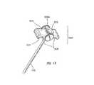
- FIG. 17illustrates a side-elevation view illustrating a spring embodiment of the tube associated with the sheath of the present invention
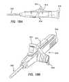
- FIG. 18Aillustrates a side view of an actuation hand-piece in accordance with one embodiment of the present invention
- FIG. 18Billustrates a perspective view of an actuation hand-piece in accordance with one embodiment of the present invention
- FIG. 19illustrates a cross-sectional view of the actuation hand-piece of FIGS. 18A-B ;
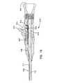
- FIG. 20illustrates a perspective view of an actuation hand-piece in accordance with one embodiment of the invention
- FIG. 21Aillustrates a top view of a disassembled actuation hand-piece of FIG. 20 ;
- FIG. 21Billustrates a cross-sectional view of the actuation hand-piece of FIG. 20 ;
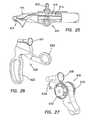
- FIG. 22illustrates a perspective view of an actuation hand-piece in accordance with one embodiment of the invention
- FIG. 23Aillustrates a cross-sectional view of the actuation hand-piece of FIG. 22 ;
- FIG. 23Billustrates a perspective view of a disassembled actuation hand-piece of FIG. 22 ;
- FIG. 24illustrates a perspective view of an actuator or actuation hand-piece in accordance with one embodiment of the invention
- FIG. 25illustrates a cross-sectional view of the actuation hand-piece of FIG. 24 ;
- FIG. 26illustrates a perspective view of an actuation hand-piece in accordance with one embodiment of the present invention
- FIG. 27illustrates a perspective view of an actuation hand-piece in accordance with one embodiment of the present invention
- FIG. 28Aillustrates a side view of an actuator or actuation hand-piece in accordance with one embodiment of the invention
- FIG. 28Billustrates another side view of the actuation hand-piece of FIG.
- FIG. 29illustrates a perspective view of an actuation hand-piece in accordance with one embodiment of the present invention.
- FIG. 30illustrates a cross-sectional view of a connector in accordance with one embodiment of the present invention
- FIG. 31illustrates a cross-sectional view of the actuation hand-piece of FIG. 29 ;
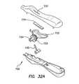
- FIGS. 32A-Billustrate perspective views of a disassembled actuation hand-piece in accordance with one embodiment of the present invention
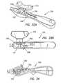
- FIGS. 33A-Billustrate other perspective views of the disassembled actuation hand-piece of FIGS. 32 A-B;
- FIG. 34illustrates a cross-sectional view of the actuation hand-piece of FIG. 32 ;
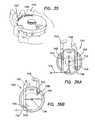
- FIG. 35illustrates a perspective view of an actuation hand-piece in accordance with one embodiment of the present invention
- FIGS. 36A-Billustrate cross-sectional views of the actuation hand-piece of FIG. 35 ;
- FIGS. 37-38illustrate perspective views of embodiments of components of the actuation hand-piece of FIG. 35 ;
- FIG. 39illustrates a view of an actuation hand-piece in accordance with one embodiment of the present invention.
- FIG. 40illustrates a perspective view of an actuation hand-piece in accordance with one embodiment of the present invention
- FIG. 41illustrates a perspective view of an actuation hand-piece in accordance with one embodiment of the present invention
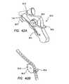
- FIG. 42Aillustrates a perspective view of an actuation hand-piece in accordance with one embodiment of the present invention
- FIG. 42Billustrates a perspective view of one embodiment of components of the actuation hand-piece of FIG. 42A ;
- FIG. 42-45 and 46 A-Cillustrate cross-sectional views of embodiments of an access sheath in various stages of fabrication in accordance with the present invention.
- FIGS. 1-3illustrate a surgical access device or steerable kink resistant access device 100 in accordance with the one embodiment of the present invention for use in, among other fields, cardiology, urology, radiology, electrophysiology and gastroenterology.
- Access device 100comprises an access sheath 102 having a longitudinal axis 103 extending from a proximal end to a distal end, and a handle portion 104 operatively connected to the proximal end of the access sheath 102 .
- the access sheath 102includes an elongated body 105 and a steerable region or portion 106 . It is appreciated that the steerable portion 106 may be formed anywhere along the access sheath 102 .
- the steerable portion 106 and the elongated body 105may have variable stiffness depending on the application of the access sheath 102 .
- the access sheath 102has an outside diameter sufficiently small so that it may be inserted into a body cavity or conduit.
- the access sheath 102typically has two internal lumen, a primary lumen 112 and a secondary lumen 114 , as illustrated in FIG. 2 .
- the primary lumen 112is sized and configured as an access to a surgical site or the target of a surgical procedure. In particular, primary lumen 112 operates to advance diagnostic and therapeutic elements to the surgical site or target.
- the secondary lumen 114is sized and configured to contain a tensioning device 116 such as a control or pull wire that, when acted upon, will deflect the steerable portion 106 of the access sheath 102 .
- the tensioning device 116extends through the secondary lumen 114 and is attached to the actuator or handle portion 104 at one end and to a distal portion 107 of the steerable portion 106 at the other end.
- the handle portion 104may include a thumb-actuated knob 118 controlling the tensioning device 116 .
- knob 118may be drawn proximally in a direction 119 to provide tension to the tensioning device 116 or cause the tensioning device to tense or distally in a direction 120 to loosen tension or cause the tensioning device 116 to loosen.
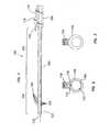
- FIGS. 13-16illustrate an actuator or actuation hand-piece 500 having a proximally-facing portion 502 , a distally-facing portion 504 , hand-engaging extensions 506 , and at least one thumbwheel member 508 a,b .
- the proximally-facing portion 502has a generally flat support surface and includes a funnel-shaped entry portion 510 .
- the funnel-shaped entry portion 510is sized and configured to guide an obturator and other instrumentation into a working channel within the hand-piece 500 .
- the distally-facing portion 504is connected to the access sheath 102 .
- the working channel of hand-piece 500is sized and configured to form a transition into the primary lumen 112 of the access sheath 102 .
- the hand-engaging extensions 506are sized and shaped to accommodate two extended human fingers in a holding position.
- the at least one thumbwheel 508allows a user to deflect the steerable portion 106 of the access sheath 102 .
- the steerable portion 106may be deflected through the action of a tensioning device 116 , such as a pull wire or control wire associated with the secondary lumen 114 within the access sheath 102 .
- the tensioning device 116may be connected to an axle positioned between two thumbwheels 508 a and 508 b or at least one thumbwheel and an opposing side of hand-piece 500 . As the thumbwheels 508 a and 508 b are rotated, the tensioning device 116 imparts a pulling force on the steerable portion 106 of sheath 102 , thereby causing portion 106 to deflect.
- directional indicators 512may be placed on each of hand-engaging extensions 506 of hand-piece 500 to indicate the direction of distal deflection or bending of access sheath 102 .
- the actuator or actuation hand-piece of the inventionmay be remotely attached to the associated access sheath to control the tensioning and loosening of the tensioning device.
- the hand-piecemay be connected to a flexible tubing or body, which is connected to the access sheath.
- the thumbwheels of the hand-piecemay be placed away from the surgical site so that they do not prevent or interfere with full insertion of the working length of the access sheath.
- the access sheathmay comprise a plurality of pull wires attached to a plurality of thumbwheels of an actuation hand-piece to deflect the steerable portion of the sheath in different directions.
- the access sheath 102comprises an extruded multi-lumen plastic tube.
- the access sheath 102may be molded from a plastic or rubber-like material.
- Preferred materialsinclude polyvinyl chloride, polyester, silicone elastomer, natural or synthetic rubber, polyurethane or the like. The materials may range in hardness from around 40 Shore A to 70 Shore D. These materials are generally flexible and durable.
- a structuresuch as a spring can be molded into the tube of the sheath to facilitate kink resistance.
- the access sheath 102may be formed with an inner plastic body 610 , surrounded by a metal spring coil 612 , which is further covered by an outer body 614 .
- This particular embodiment of access sheath 102provides a high degree of kink resistance.
- the inner body 610provides a smooth surface within the sheath, which facilitates passage of instrumentation.
- the spring coil 612adds kink resistance to the sheath tube, while the outer body 614 provides a suitable covering for the coils of the spring 612 .
- a tightly wound springmay be placed in the secondary lumen 114 of the access sheath 102 to facilitate movement of the tensioning device 116 inserted there through.
- the springmay be bonded or otherwise fixed to the secondary lumen 114 .
- the springoperates to isolate forces applied by the tensioning device 116 , which is inserted through the spring and is attached to the distal portion 107 of the steerable portion 106 .
- the springadds stability and rigidity to the elongate body 105 when the tensioning device 116 is acted upon such that only the steerable portion 106 is bent or steered.
- the springoperates to direct the tension force applied on the device 116 to the steerable portion 106 so as to allow deflection of only the portion 106 and not the elongate body 105 . That is, the tension force is isolated to the steerable portion 106 , which may be formed anywhere along the access sheath 102 .
- the springmay be coated with a lubricious material further facilitating movement of the tensioning device 116 .
- the springmay line or cover the inner surface area of the entire secondary lumen 114 or just portions of the secondary lumen 114 to facilitate isolation of the tension force.
- the springmay be constructed from a 0.005-inch diameter wire that is tightly wound forming a closed wound spring having a 0.02-inch outer diameter.
- the distal 0.5 to 2 inches of the springmay be stretched to an open wound state such that the windings have an approximately 0.02-inch gap between them.
- This stretched portion of the springfacilitates isolation of the tension force applied by the tensioning device 116 .
- the springmay be coated, for example, in a plastic jacket and bonded to the secondary lumen 114 from the proximal end of the spring to the proximal end of the stretched portion. The stretched portion is then left free to move and/or compress in the plastic jacket.
- the distal end of the stretched portionmay be anchored to the distal end of the access sheath 102 along with the tensioning device 116 .
- the distal end of the plastic jacketmay also be bonded to the distal end of the access sheath 102 along with the tensioning device 116 and the spring although these elements do not require a common bonding point or bonding method.
- the proximal end of the access sheath 102may be directly or remotely attached to handle portion 104 or actuator or hand-piece 500 , which allows the operator to place tension on the tensioning device 116 , such as a control or pull wire, while maintaining the position of the catheter.
- This tensioncauses the stretched portion of the 0.02-inch diameter spring to collapse and this, in turn, forces the sheath to bend in the region where the stretched portion of the spring is located.
- the stretched portionmay be formed anywhere along the catheter or surgical access device that may require bending, and is not limited to the distal end of the device.
- more than one deflection assembly of spring and tensioning devicemay be added to the access device to create deflection in different regions or planes. The amount of bending or deflection will in some way be proportional to the amount of force or tension placed on the tensioning device.
- the tensioning device 116is, in one embodiment, a control or pull wire made of Nitinol, a braided cable or any flexible strand or wire.
- the control wireis inserted through the spring such that it runs through the secondary lumen 114 as illustrated in FIG. 5 .
- the proximal end of the tensioning device 116e.g., a control or pull wire, is connected to an actuator such as the knob 118 of the handle portion 104 .
- the distal end of the control or pull wireas previously described, is attached to the distal portion 107 of steerable portion 106 .
- the tensioning device 416may be a flattened or flat member extending through a secondary lumen 414 of at least the steerable portion 106 of the access sheath 102 .
- the steerable portion 106includes a plurality of radially and longitudinally spaced notches 108 and slits 110 disposed on opposite sides of each other facilitating radial deflection of the distal portion 107 in a desired direction or angle.
- the notches 108 and slits 110are cut into the access sheath 102 across the longitudinal axis 103 .
- the degree of deflectionmay vary greatly based on many factors such as the number, size, direction, shape and spacing of the notches 108 and slits 110 .
- the notches 108are cut deeper and wider at a distal end 150 than they are at a proximal end 152 of steerable portion 106 .
- the slits 110comprise of very shallow cuts to provide a reduction in resistance to stretching as the steerable portion 106 is bent or deflected toward the notches 108 .
- the notches 108 and slits 110may be of any desired width, length, depth and shape.
- the number of notches 108 and slits 110 in the steerable portion 106can be varied in accordance with the use and flexure requirements of the access sheath 102 .
- the slits 110are narrower and shallower than the notches 108 to provide a “weak-side/strong-side” arrangement of the steerable portion 106 so as to allow the access sheath 102 to be predisposed to bending in the desired direction. That is, when the control wire of the tensioning device 116 is drawn proximally as illustrated in FIG.
- the more flexible side of the steerable portion 106i.e., the side with notches 108
- the more flexible side of the steerable portion 106will give first thereby bending in the direction of the notches.
- the distal end 150 of the steerable portion 106 with the deeper and wider notches 108will bend first as the bending progressively moves toward the proximal end 152 having shallower and narrower notches. It is appreciated that the notches 108 may extend through the wall of the access sheath 102 .
- the notches 108provide a “weak-side” or preferred bend path as the notches 108 are closed when bent. It can be seen that the notches 108 are wedge-shaped and have material removed from them. There is, therefore, sufficient room for the material adjacent to each notch to approximate, thereby shortening the length of the steerable portion 106 on the weak-side.
- the slits 110are shallow radial cuts made directly opposite the notches 108 with little or no material removed. The slits 110 provide the mechanical equivalent of increased plastic elasticity.
- the slits 110allow the material of the steerable portion 106 to stretch beyond the intrinsic properties of the material itself.
- the primary lumen 112 of the steerable portion 106will not collapse when deformed or bent into a tight circular profile as can be seen in FIG. 6 .
- the slits 110will only open to provide an elongation of the “strong-side” and will not collapse to provide a shortening of the “strong-side”.
- the material on either side of the notches 108 and slits 110maintains the general elongate dimension and forms a continuum of the access sheath 102 .
- the distal end 200 of the steerable portion 106has a generally rounded off wall section 205 providing an atraumatic insertion tip.
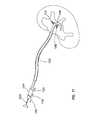
- Surgical instrumentssuch as an ureteroscope 300 may be directed through a steerable access sheath as illustrated in FIGS. 6 and 11 .
- the steerable access sheathmay be used to pass the ureteroscope 300 into the upper and lower poles of the renal calices as generally illustrated in FIG. 11 .
- flexible ureteroscopes and other flexible endoluminal scopesincluding completely passive scopes, may be accurately positioned with the assistance of the steerable access sheaths of the present invention.
- FIGS. 18-19illustrate an actuation hand-piece or actuator 510 in line with the access sheath 102 .
- the proximal end of the actuator 510includes a funnel-shaped entry portion 516 that is sized and configured to guide an obturator, dilator, ureteroscope and other instrumentation into a working channel 518 within the actuator 510 .
- the working channel 518 of actuator 510is sized and configured to form a transition into the primary lumen 112 of the access sheath 102 .
- the tensioning device 116 extending through the secondary lumen 114is attached to a bracket 512 .
- a proximal end of the tensioning device 116is balled, crimped, or otherwise sized or deformed to secure the tensioning device 116 to the bracket 512 .
- the bracket 512is further connected to a slider 514 .
- a lever 511 connected to the slider 514allows a user to move the slider 514 and thereby control tensioning device 116 .
- the hand-piece 510includes a pivotable lever 519 connected to lever 511 . Pivotable lever 519 provides a counter actuation point relative to lever 511 . In other words, as the lever 519 is moved distally, lever 511 moves proximally and vice versa.
- the tensioning device 116imparts a pulling force on the steerable portion 106 ( FIG. 1 ) of access sheath 102 thereby deflecting the steerable portion 106 .
- the slider 514also includes a plurality of teeth 515 that operatively engage corresponding teeth 517 along the inside of the hand-piece 510 . Therefore, as the slider 514 is moved proximally and distally, this engagement allows incremental control of the deflection and straightening of the steerable region or portion 106 of the access sheath 102 .
- an embodiment of an actuator or actuation hand-piece 520also adapted to be in line with the access sheath 102 is shown.
- the proximal end of the hand-piece 520includes a funnel-shaped entry portion 522 connected within the hand-piece 520 to access a working channel 524 which forms a transition into the primary lumen 112 of the access sheath 102 .
- Tensioning device 116 extending through the secondary lumen 114is attached to a threaded cylinder 526 .
- a knob 527 surrounding the cylinder 526is correspondingly threaded to engage the cylinder 526 , which allows a user with a twist or turn of the knob 527 in one direction, e.g., clockwise, to move the cylinder 526 linearly, e.g., proximally.
- tensioning device 116also traverses towards the proximal end of the hand-piece 520 to impart a pulling force on the steerable portion 106 thereby deflecting the steerable portion 106 of the access sheath 102 .
- the knob 527is also allowed to move in the opposite direction moving the threaded cylinder 526 distally to straighten the steerable portion 106 of the access sheath 102 . Therefore, the hand-piece 520 provides a rotary or scroll type control of the deflection and/or straightening of the steerable portion 106 of the access sheath 102 .
- FIGS. 22-24illustrate an actuator or actuation hand-piece 530 in line with the access sheath 102 , with the hand-piece 530 including a funnel-shaped entry portion 531 .
- An axle 532 disposed within the hand-piece 530is connected to a tensioning device from the access sheath 102 and connected to two thumb-actuated dials or wheels 533 and 534 .
- the wheels 533 and 534are partially disposed within the hand-piece 530 .
- the wheel 533 and/or wheel 534control the tensioning device.
- the wheel 533turned clockwise causes the tensioning device to be drawn proximally to provide tension to the tensioning device, e.g., one or more a pull or control wires.
- the control wire(s) being drawn proximallywraps or winds around the axle 532 in the hand-piece 530 .
- the wheels 533 and 534also include ratchet wheels or a number of radially extending teeth 535 connected to or integrated with the wheels 533 and 534 .
- the teeth 535operatively engage with a corresponding lever or pawl 536 connected to a trigger 537 .
- the pawl 536 engaged with the teeth 535permits rotational movement of the wheels 533 and 534 in one direction, e.g., a clockwise direction, while preventing rotational movement in the opposite direction.
- incremental control of the deflection of the steerable portion 106 of the access sheath 102is provided as the axle 532 in the hand-piece 530 draws the tensioning device 116 proximally.
- the trigger 537when actuated, pivots pawl 536 causing pawl 536 to disengage from teeth 535 .
- the control wire(s)unwind or move distally from the axle 532 whereby the steerable portion 106 of the access sheath 102 straightens.
- an actuator or actuation hand-piece 610being connected yet offset from the access sheath 102 is shown.
- the offset hand-piecemay reduce the working length used in the access sheath or added to the access sheath with the hand-piece being in line with the access sheath.
- the usermay operate the hand-piece proximate to the access sheath to provide a tactile or visual feedback or reminder of the steerable portion 106 of the access sheath 102 .
- the hand-piece 610in one embodiment, includes or is connected to a connector 611 with a funnel-shaped entry portion 612 that is sized and configured to receive and guide instruments into/out of the access sheath 102 .
- the secondary lumen 114is separately connected to the hand-piece 610 .
- a conduitconnects the secondary lumen 114 and tensioning device 116 to the hand-piece 610 .
- the tensioning device 116 extending through the secondary lumen 114is attached to slider 614 .
- a lever 613 connected to the slider 614allows a user to move the slider 614 that imparts a pulling force on the steerable portion 106 to deflect the steerable portion 106 or a reduction in tension on the steerable portion 106 allowing the steerable portion 106 of the access sheath 102 to straighten.
- the slider 614in one aspect of the present invention, includes a plurality of teeth that operatively engage corresponding teeth along the inside of hand-piece 610 to provide incremental control of the deflection and/or straightening of the steerable portion 106 of the access sheath 102 .
- FIG. 26illustrates another embodiment of the present invention of an actuator or actuation hand-piece 620 offset from the access sheath 102 .
- the hand-piece 620includes a funnel-shaped entry portion 621 providing access to the primary lumen of the access sheath 102 .
- the secondary lumen and the tensioning device of the access sheath 102are also connected to the hand-piece 620 .
- the tensioning device 116is attached to a movable handle member 622 that is pivotally connected to a stationary handle member 623 .
- the tensioning deviceis connected to a semi-circular plate or disc that rotates or pivots as the movable handle member is actuated.
- Manipulation of the movable handle member 622allows a user to pull or release the tensioning device 116 to respectively deflect or straighten the steerable portion 106 of the access sheath 102 .
- a ratchet mechanismdisposed within the hand-piece 620 or between the movable handle member 622 and the stationary handle member 623 is included to provide incremental control of the tensioning device 116 and thus the deflection of the steerable portion 106 of the access sheath 102 .
- FIGS. 27-28illustrate an actuator or actuation hand-piece 630 and 630 ′ situated offset from the access sheath 102 .
- the actuation hand-piece 630 and 630 ′includes a funnel-shaped entry portion 631 and is connected to a tensioning device attached to an axle disposed within the hand-piece 630 and 630 ′.
- the axleis connected to two thumb-actuated knobs or wheels 632 and 633 .
- the wheels 632 and 633are partially disposed within the hand-piece 630 ′.
- the wheels 632 and 633control the tensioning device 116 .
- the wheel 632 and/or wheel 633may be rotated to provide tension to the tensioning device 116 , e.g., a control wire, or to loosen tension in the control wire.
- the wheel 632 and 633are connected to separate and independent control wires adapted to deflect the access sheath in an opposing manner and/or to deflect different portions of the access sheath.
- a trigger 634when actuated, locks the wheel 632 and/or wheel 633 thus preventing further movement of the tensioning device 116 and the deflection/straightening of the steerable portion 106 of the access sheath 102 .
- the trigger 634releases or disengages control of the tensioning device 116 from wheels 632 or 633 to allow the tensioning device to return to its original position.
- an actuator or actuation hand-piece 710 of the present inventionis remotely attached to an access sheath to control the tensioning and loosening of a tensioning device connected to the access sheath.
- the actuatormay be placed away from the surgical site or operating path or area so that the hand-piece does not prevent or interfere with the insertion of instruments along the working length of the access sheath.
- the remote actuatordoes not occupy or add additional working space or length to the access sheath.
- another usermay operate the actuator remotely allowing another user to focus on the surgical procedure, e.g., manipulating instruments to be or already inserted in the access sheath. Extended surgery time and confusion caused by switching between the actuator and other devices or simultaneously using the many devices may be reduced.
- the actuator 710in one embodiment, is connected to a flexible body or conduit 711 , which is connected to the access sheath 102 via a Y-connector 712 .
- the Y-connector 712includes a funnel-shaped entry portion 713 that is sized and arranged to guide instruments into the primary lumen 112 of the access sheath 102 .
- the Y-connector 712also includes a channel 714 for connecting to the flexible conduit 711 .
- the tensioning device 116extends through the secondary lumen 114 , channel 714 , and flexible conduit 711 and is attached to an axle 715 disposed within the actuator 710 .
- the axle 715is connected to a dial or knob 716 that partially extends laterally from the hand-piece 710 with finger holds disposed radially throughout the knob 716 .
- the other end of the axle 715is rotatably connected to the hand-piece 710 .
- the knob 716allows a user to control the tensioning device 116 .
- the tensioning device 116is drawn proximally to wrap or wind around the axle 715 .
- a plurality of teeth 717 radially disposed on the knob 716 within the hand-piece 710 or disposed on a separate or embedded ratchet wheeloperatively engages with a corresponding lever or pawl 718 .
- the pawl 718pivoting about a post connected to the hand-piece 710 and biased by a leaf spring 719 engages with the teeth to permit rotational movement of the knob 716 in one direction, e.g., clockwise, while preventing rotational movement in the opposite direction.
- FIGS. 32-34another embodiment of an actuator or actuation hand-piece 730 of the present invention remotely attached to an access sheath 102 is shown.
- An axle 731 disposed within the hand-piece 730is attached to the tensioning device 116 .
- the axle 731is also connected to a rotatable key or winged lever 732 extending laterally from one side of hand-piece 730 .
- the lever 732allows a user to control the tensioning device 116 .
- the tensioning device 116is drawn proximally to wrap or wind around the axle 731 in the hand-piece 730 .
- a plurality of teeth 733 radially disposed around the axle 731 or disposed on a ratchet wheel surrounding the axleoperatively engages with a corresponding pawl or cantilever arm 734 .
- the arm 734 mounted on the hand-piece 730 and engaged with the teeth 733permit rotational movement of the lever 732 and axle 731 in one direction while preventing rotational movement in the opposite direction. This engagement provides incremental control of the tensioning device 116 and thus also of the steerable portion 106 of the access sheath 102 .
- the hand-piece 730also includes a trigger lever 735 that is pivotally connected to a post in the hand-piece 730 and partially extends through a slot 737 in the hand-piece 730 .
- the lever 735when actuated, e.g., pulled proximally, moves the cantilever arm 734 to disengage from the teeth 733 to allow the axle 731 to freely rotate. Therefore, the tensioning device 116 connected to the axle 731 unwinds and/or moves distally from the axle 731 causing the steerable portion 106 of the access sheath 102 to straighten.
- FIGS. 35-38another embodiment of an actuator or actuation hand-piece 740 of the present invention that is remotely attached to an access sheath 102 to control the tensioning and loosening of the tensioning device 116 is shown.
- an axle 741Disposed within the hand-piece 740 is an axle 741 , which is attached to tensioning device 116 .
- the axle 741is connected to a slotted wheel 742 that is partially rotatable within the hand-piece 740 .
- Generally opposing slots 743 and 744are disposed in the slotted wheel through which respective dowels or pins 745 and 746 extend through and connect to distal ends of respective button arms 747 and 748 .
- Proximal ends of button arms 747 and 748extend through openings in the hand-piece 740 .
- the button arm 748when the button arm 748 is lowered, the button arm 747 rises as the slotted wheel 742 rotates clockwise. As a result, the tensioning device 116 connected to axle 741 is not drawn to the hand-piece 740 , such that the steerable portion 106 of the access sheath 102 is substantially straight.
- the button arm 747When button arm 747 is lowered, the button arm 748 rises and the slotted wheel 742 rotates causing the tensioning device 116 to be pulled by rotating axle 741 such that the steerable portion 106 of access sheath 102 deflects.
- the hand-piece 740includes guides 749 for aligning and guiding traversal of the button arms 747 and 748 and slots (not shown) for assisting linear movement of the pins 745 and 746 as the button arms move.
- the slotted wheel 742also includes one or more openings along the circumference of the wheel to permit rotation of the wheel without interfering with the guides 749 .
- the axle 741is connected to a screw knob for adjusting the tension or pre-winding the tensioning device 116 around the axle 741 .
- the hand-piece 750fits within a user's hand in that a fist closing motion moves a t-bar 753 proximally deflecting the access sheath 102 and an opening motion moves the t-bar 753 distally allowing the access sheath 102 to straighten.
- the hand-piece 750includes finger-extension members 754 to provide one or more fingers on each member 754 to grasp the t-bar 753 .
- a distally flared end 756 of a tube 751is also provided for resting in the palm of a hand.
- the plate 752is connected to the t-bar 753 that is slidably connected to tube 751 .
- an adjustment screwis connected to the t-bar 753 to adjust the location of the plate 752 relative to the t-bar 753 and within the tube 751 .
- a set of teeth 755 within tube 751operatively engages with a tooth or detent on t-bar 753 as the t-bar 753 moves.
- plate 751With the t-bar 753 moving proximally, plate 751 also moves proximally thereby pulling tensioning device 116 to cause the steerable portion 106 of the access sheath 102 to deflect. Similarly, as the t-bar 753 and plate 751 moves distally, the tensioning device 116 loosens and thus the steerable portion 106 straightens. As such, this engagement provides incremental control of the deflection and/or straightening of the steerable portion 106 of the access sheath 102 .
- a spring-loaded button 757 on one end of the t-bar 753when actuated, disengages the tooth on t-bar 753 from the teeth 755 within tube 751 allowing the t-bar 753 to move freely.
- FIGS. 40-41illustrate another embodiment of the present invention of an actuator or actuation hand-piece 760 and 760 ′ each remotely attachable to the access sheath 102 .
- the hand-piece 760 and 760 ′are connected to a flexible body or tube 761 through which the tensioning device 116 extends.
- the tensioning device 116is attached to a first handle member 762 that is pivotally connected to a second handle member 763 . Actuation of the first handle member 762 allows a user to pull or release the tensioning device 116 to respectively deflect or straighten the steerable portion 106 of the access sheath 102 .
- a ratchet assemblyis included to provide incremental control of the tensioning device 116 and thus the deflection of the steerable portion 106 of the access sheath 102 .
- the access sheathmay comprise a plurality of pull wires attached to a plurality of thumbwheels, axles, knobs or other types of movable components of an actuation hand-piece to deflect the steerable portion of the sheath in different directions.
- the tensioning devicemay be hydraulic, pneumatic or electronic in nature and the actuation hand-piece may instead be foot, finger or otherwise sensor actuated and may include corresponding foot, finger or otherwise sensor extensions.
- the tensioning device 116is connected to a belt 811 .
- the belt 811acts as an intermediary between the tensioning device 116 and a movable component 818 in the hand-piece 810 .
- the movable componentmay also be, for example, slider 514 or 614 ( FIGS. 18B and 24 ), cylinder 526 ( FIG. 20 ), movable handle member 622 ( FIG. 26 ), axle 715 or 731 ( FIGS. 31 and 32 ), and various other movable components fully or partially disposed within or otherwise part of an actuator or hand-piece which is connectable to the tensioning device 116 .
- tensioning device 116Through belt 811 , stress or forces that may be applied by or result from the movable component 818 is displaced from the tensioning device 116 . Therefore, stress experienced by the tensioning device 116 caused by the actuation of the hand-piece may be reduced.
- the belt 811includes a number of apertures 812 for engaging teeth 813 radially disposed on the movable component 818 of the hand-piece 810 .
- the belt 811includes teeth or protrusions for engaging corresponding apertures, teeth or protrusions of the movable component 818 . With either engagement, incremental control of the tensioning device 116 is provided. As such, the belt 811 draws the tensioning device 116 proximally as the knob is rotated in one direction and rotating the knob in the opposite direction, allows the tensioning device to withdraw from the hand-piece 810 .
- a pin or roller 814may also be included to assist in the engagement of the belt 811 with a movable component 818 of the hand-piece 810 .
- the belt 811is pliable.
- a plate, bar, or a less flexible componentmay be connected to the belt 811 for drawing or releasing the belt 811 in conjunction with or without the movable component 818 .
- a u-shaped lever 815is connected to a knob 816 that is disposed on one or both sides of the hand-piece 810 and is connected to the movable component 818 in the hand-piece 810 .
- a usercan control the movement/tension of the tensioning device 116 and thus the deflection and straightening of the steerable portion 106 of the access sheath 102 .
- a plateis connected to the u-shaped lever 815 and the belt 811 to draw and release the tensioning device 116 .
- a trigger 817when actuated, locks the belt 811 , the movable component 818 or the u-shaped lever 815 , thus preventing further movement of the tensioning device 116 and the deflection/straightening of the steerable portion 106 of the access sheath 102 .
- the trigger 817releases or disengages control of the tensioning device 116 from the belt 811 , the movable component 818 or the u-shaped lever 815 to allow the tensioning device 116 to return to its original position or state.
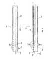
- a wire 801is wound around a support member or mandrel 802 in which the size and shape of mandrel generally defines the size and shape of primary lumen 112 of the access sheath 102 .
- the mandrelin one embodiment, is stainless steel and made of or is coated with a low friction material or surface, e.g., Teflon or various mold releases, allowing for the mandrel to be easily removed from the access sheath 102 .
- the wire 801is wound in an over counter fashion by using anchors or starting and stopping points substantially orthogonal of each other and thus winding the wire 801 in an oblique line along mandrel 802 . As such, the wire 801 is wound such that the wire's tendency to unwind is counteracted.
- the mandrel 802is coated with or inserted into a plastic or PVC material tube to allow instruments and the like to be smoothly inserted into the primary lumen without interference from the wire 801 .
- the wire 801in one embodiment, is a plastic coated wire and particularly, a stainless steel co-extruded wire with an approximate diameter of 0.006 inches fused, coated or otherwise included with a plastic material to make the total diameter of the wire 801 to be about 0.012 inches.
- the mandrel 802 including wire 801is placed into or inserted into a control tube. Air, in one embodiment, is supplied, e.g., at 100 PSI, on the opposite end of insertion to assist insertion of the mandrel 802 by expanding the control tube.
- the control tubein one embodiment, may be made of silicon or a material with a higher melting point than the plastic coating of wire 801 . This assembly is then heated such that the plastic coating of wire 801 melts and adheres to itself to form a generally continuous tubular structure or major tube 803 . The control tube is then removed.
- a minor tube 804is placed on or included with the major tube 803 .
- the minor tube 804is longer than the major tube 803 and thus extends substantially further along the mandrel 802 than the major tube 803 .
- Extending within a portion of the minor tube 804is a generally tubular structure or inner tube 805 that is about as long as the major tube 803 .
- the inner tube 805is made of polyimide and the minor tube 804 is made of carbothane that when heated adheres to the inner tube 805 , the major tube 803 and other portions of the access sheath, which are described below, that surrounds the outer periphery of the minor tube 804 .
- the inner tube 805 within the minor tube 804is adapted to receive the support wire 806 .
- the size and shape of the support wire 806 along with the inner tube 805generally defines the size and shape of the secondary lumen 114 of the access sheath 102 .
- the support wireis a stainless steel wire with a diameter of about 0.12 inches.
- the support wire 806is secured to a proximal end of the mandrel 802 , threaded through the inner tube 805 and the minor tube 804 and secured to the distal end of the mandrel 802 .
- the support wire 806secures the minor tube 804 to the major tube 803 .
- the minor tube 804extends along the mandrel 802 substantially more than the inner tube 805 .
- the length of the minor tube 804is longer than the inner tube 805 .
- the minor tube 804is also more flexible than the inner tube 805 .
- the portion from the end point of the inner tube 805 and/or the major tube 803 to near the end point of the minor tube 804eventually defines the steerable portion 106 of the access sheath 102 .
- the minor tube 804is shorter and less flexible than the inner tube 805 .
- the portion from the end point of the minor tube 804 and/or the major tube 803 to near the end point of the inner tube 805eventually defines the steerable portion 106 of the access sheath 102 .
- the minor tube 804 , inner tube 805 and the major tube 803are placed into a final tube to enclose the minor tube 804 and inner tube 805 between the major tube 803 and the final tube.
- This assemblyis placed into or inserted into a control tube such that the assembly adheres or bonds together and then the control tube is removed.
- the minor tube 804 or the inner tube 805is rigid, e.g., a stainless steel tube, to assist in the deflection of the steerable region 106 .
- the rigidity of the minor tube 804 or inner tube 804prevents the non-steerable portion of the access sheath 102 from bowing.
- the tubeshifts the force caused by the tensioning device 116 to deflect the steerable region directly towards or at the steerable region 106 .
- a rigid secondary lumen formed by the rigid tubemay assist in the protection of the tensioning device and instruments inserted or withdrawn from the primary lumen.
- a wire 807is wound around the minor tube 804 , the inner tube 805 and the major tube 803 . In one embodiment, where the final tube is utilized, the wire 807 is also wound around the final tube. In one embodiment, the wire 807 is similar in construction or composition as that of wire 801 and/or extends slightly beyond the distal end of the minor tube 804 or inner tube 805 .
- a support tipin one embodiment, is placed on a distal end or slightly beyond the distal end of the wire 807 to assist in securing the wire 807 around the minor tube 804 or inner tube 805 and/or to provide an atraumatic tip.
- the support tipmay be a 75 Shore D material.
- the mandrel 802 with rest of the assemblyis inserted into a control tube.
- airin one embodiment, is supplied on the opposite end of insertion to assist insertion of the mandrel 802 by expanding the control tube.
- a support tubeis used to temporarily encompass the control tube when the tube is pressurized in the event the tube breaks down.
- control tube with the assemblyis heated such that the plastic coating of wire 807 melts and adheres to itself to form a generally continuous tubular structure or tube 808 .
- the control tubeis then removed.
- the control tube and assemblyare heated at around 165 degrees plus or minus about five to ten degrees for about ten to fifteen minutes. As such, an access sheath 102 with a variable flexibility is created.
- the support wire 806is disconnected from the mandrel 802 .
- the support wire 806 on the distal end of the mandrel 802is cut and then the mandrel 802 is withdrawn from the access sheath 803 .
- a tensioning devicee.g., a pull wire
- the access sheathis deflectable and controllable.
- the tensioning deviceis knotted or looped around an opening or cut in the access sheath, the support tip and/or between loops in the wire 807 and back through itself.
- a catch wire threaded through the inner tube 805 and the minor tube 804hooks or otherwise attaches to the tensioning device.
- the catch wireis removed out the proximal end of the access sheath thereby threading the tensioning device through and out the proximal end of the access sheath 102 .
- the support wire 806has a diameter sufficiently larger than the diameter of the tensioning device, the catch wire or loops and hooks of the catch wire to permit easy passage of these devices through the secondary lumen of the access sheath 102 .
- a secondary support tipin one embodiment, is placed on the distal end of the access sheath 102 to assist in securing the tensioning device to the access sheath and/or to provide an atraumatic tip.
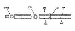
- the distal end 809 a of the access sheath 102is tapered and thus has a smaller diameter than the proximal end 809 b of the access sheath 803 .
- the primary lumen 112 and secondary lumen 114 diametersremain substantially constant throughout the access sheath 102 .
- the tapering or reduced diameter of the access sheathis a result of the halting or non-extension of the inner tube 805 or minor tube 804 , in one embodiment, and the major tube 803 along the length of the mandrel 802 .
- the steerable portion 106includes a reduced amount of materials and more flexible materials, and thus the steerable portion is easily deflected, bent, shaped or curved in response to the manipulation of the attached tensioning device while the other portion of the access sheath 102 , including more material and less flexible material, remains substantially fixed, e.g., straight and substantially in the same plane, preventing any inadvertent or unintended movement of the access sheath.
- the steerable region 106 of the access sheath 102is reinforced by wire 807 , the steerable region 106 is strengthen such that a flexible, pre-bendable or otherwise not actively controllable instrument may be controllably deflected dynamically as the steerable region 106 is controlled.
- an actively deflectable surgical instrumentmay have a complicated construction providing components, e.g., optics or clamps, to perform its surgical function and components to perform the active deflection. Therefore, such instruments may be fragile or if broken may be expensive to replace or repair or still usable as a surgical instrument but not actively deflectable.
- the strengthen steerable region 106may replace the components or use of the components in such surgical instruments or induce an broken instrument to be controllably deflected thereby reducing replacement, repair and/or construction costs, reducing wear and tear of such instruments and increasing the life of such instruments.
- the reinforced access sheath 102 through wire 807 and/or wire 801allows the size and shape of the primary lumen to remain substantially constant throughout the access sheath 102 , thereby reducing forces on instruments placed within the access sheath which may extend the life of these instruments.
- the forces or stress accumulated along the access sheath that may cause kinks in the access sheathare also distributed along the access sheath due to the composite construction of the access sheath described above and are further counteracted by the wire coils, e.g., wire 807 and 803 .
- the wire coilsalso allow the access sheath walls to be very thin without reducing durability or strength in the access sheath.
- the overall or outer diameter of the access sheathmay be small, which may also reduce the incision or insertion point for the access sheath, without reducing the size or diameter of the primary lumen.
- the access sheath of various embodiments of the present inventionhas thin walled portions, a large lumen, an atraumatic end, and a kink resistant construction and is strong, stiff and yet flexible enough to be intricately guided through the body cavity or tissue.
- the wire coilsare wound in a multifilar fashion with materials having alternating durometers.
- various embodiments of access sheaths and actuators previously described, here now referred to as the access sheathallows for gradual and atraumatic dilation of the ureter while being placed.
- an instrument or device used to stretch or enlarge an openinge.g., a dilator
- an instrument or device used to stretch or enlarge an openinge.g., a dilator
- the access sheathallows for continued access to the desired area, for example, for the placement of an ureteroscope and other therapeutic instruments, while providing protection of the ureter.
- the access sheathmay protect the ureter during the placement and removal of devices within the access sheath, during the removal of stone fragments or other tissue, and during the removal of a potentially cancerous biopsy specimen.
- an urologistmay effectively and efficiently locate stones and stone fragments within the kidney.
- a stone burdenis found in one of the calyces of the kidney, especially in the lower pole portion of the kidney; it may be difficult for the urologist to continue to go back to the same calyx or location to remove the burden.
- the amount of time savedmay be significant, especially if there is a large stone burden within the kidney. Additionally, the likelihood of doing damage to the kidney due to the additional manipulation that takes place every time the ureteroscope is placed back into the kidney may be reduced. Thus, with the access sheath, one can keep the sheath deflected towards a particular calyx and remove the stone burden without having to find the calyx each and every time a fragment is removed.
- the urologistmay sometimes use the inside walls of the kidney to help deflect the ureteroscope to enter into a particular difficult locale.
- the access sheath 102instead of using the inside wall to help deflect the ureteroscope the access sheath may be used. Also, as previously mentioned, this will also help reduce the “wear and tear” on surgical instruments, such as ureteroscopes.
- the deflecting mechanism with the ureteroscopeif provided, can be damaged often and expensive repair.
- the use of the access sheathmay reduce the damage to the ureteroscope when it is used to help manipulate the ureteroscope to desired locations within the kidney.
- the use of the access sheath 102may also help a lesser-experienced urologist perform the same difficult procedure as their more experienced colleagues.
- the urologistmay access the lower pole of the kidney in order to remove a stone burden.
- By performing this procedure in a retrograde fashionone can reduce a patient's recovery time. If an urologist were neither skilled nor comfortable with using an ureteroscope in a retrograde fashion to remove a stone burden from a kidney's lower pole, the urologist would typically approach the stone burden in an antegrade fashion. This places a sheath percutaneously and thus may add additional recovery time for a patient as well as potentially increasing morbidity.
- an urologistmay efficiently and effectively locate and remove a stone burden within the lower pole of a kidney.
- the access sheathcan also be used in an antegrade fashion and will provide the same or similar features described above, however access in this manner may not be the preferred method.
- the present inventionprovides a steerable kink resistant access device.
- this inventionhas been described in certain specific embodiments, many additional modifications and variations would be apparent to those skilled in the art. It is therefore to be understood that this invention may be practiced otherwise than specifically described, including various changes in the size, shape and materials, without departing from the scope and spirit of the present invention.
- embodiments of the present inventionshould be considered in all respects as illustrative and not restrictive, the scope of the present invention to be determined by the appended claims and their equivalents rather than the foregoing description.
Landscapes
- Health & Medical Sciences (AREA)
- Life Sciences & Earth Sciences (AREA)
- Surgery (AREA)
- Engineering & Computer Science (AREA)
- Medical Informatics (AREA)
- Nuclear Medicine, Radiotherapy & Molecular Imaging (AREA)
- Biomedical Technology (AREA)
- Heart & Thoracic Surgery (AREA)
- Pathology (AREA)
- Molecular Biology (AREA)
- Animal Behavior & Ethology (AREA)
- General Health & Medical Sciences (AREA)
- Public Health (AREA)
- Veterinary Medicine (AREA)
- Mechanical Engineering (AREA)
- Surgical Instruments (AREA)
- Media Introduction/Drainage Providing Device (AREA)
Abstract
Description
Claims (20)
Priority Applications (2)
| Application Number | Priority Date | Filing Date | Title |
|---|---|---|---|
| US12/950,782US8721826B2 (en) | 2002-11-15 | 2010-11-19 | Steerable kink-resistant sheath |
| US14/164,954US9675378B2 (en) | 2002-11-15 | 2014-01-27 | Steerable kink-resistant sheath |
Applications Claiming Priority (6)
| Application Number | Priority Date | Filing Date | Title |
|---|---|---|---|
| US10/298,116US7005026B2 (en) | 2002-11-15 | 2002-11-15 | Kink-resistant access sheath and method of making same |
| US46531003P | 2003-04-25 | 2003-04-25 | |
| US10/766,138US20050165366A1 (en) | 2004-01-28 | 2004-01-28 | Medical tubing having variable characteristics and method of making same |
| US10/832,867US20050004515A1 (en) | 2002-11-15 | 2004-04-26 | Steerable kink resistant sheath |
| US11/695,449US7850811B2 (en) | 2002-11-15 | 2007-04-02 | Steerable kink-resistant sheath |
| US12/950,782US8721826B2 (en) | 2002-11-15 | 2010-11-19 | Steerable kink-resistant sheath |
Related Parent Applications (1)
| Application Number | Title | Priority Date | Filing Date |
|---|---|---|---|
| US11/695,449ContinuationUS7850811B2 (en) | 2002-11-15 | 2007-04-02 | Steerable kink-resistant sheath |
Related Child Applications (1)
| Application Number | Title | Priority Date | Filing Date |
|---|---|---|---|
| US14/164,954ContinuationUS9675378B2 (en) | 2002-11-15 | 2014-01-27 | Steerable kink-resistant sheath |
Publications (2)
| Publication Number | Publication Date |
|---|---|
| US20110066105A1 US20110066105A1 (en) | 2011-03-17 |
| US8721826B2true US8721826B2 (en) | 2014-05-13 |
Family
ID=38788740
Family Applications (4)
| Application Number | Title | Priority Date | Filing Date |
|---|---|---|---|
| US10/832,867AbandonedUS20050004515A1 (en) | 2002-11-15 | 2004-04-26 | Steerable kink resistant sheath |
| US11/695,449Expired - Fee RelatedUS7850811B2 (en) | 2002-11-15 | 2007-04-02 | Steerable kink-resistant sheath |
| US12/950,782Expired - Fee RelatedUS8721826B2 (en) | 2002-11-15 | 2010-11-19 | Steerable kink-resistant sheath |
| US14/164,954Expired - Fee RelatedUS9675378B2 (en) | 2002-11-15 | 2014-01-27 | Steerable kink-resistant sheath |
Family Applications Before (2)
| Application Number | Title | Priority Date | Filing Date |
|---|---|---|---|
| US10/832,867AbandonedUS20050004515A1 (en) | 2002-11-15 | 2004-04-26 | Steerable kink resistant sheath |
| US11/695,449Expired - Fee RelatedUS7850811B2 (en) | 2002-11-15 | 2007-04-02 | Steerable kink-resistant sheath |
Family Applications After (1)
| Application Number | Title | Priority Date | Filing Date |
|---|---|---|---|
| US14/164,954Expired - Fee RelatedUS9675378B2 (en) | 2002-11-15 | 2014-01-27 | Steerable kink-resistant sheath |
Country Status (1)
| Country | Link |
|---|---|
| US (4) | US20050004515A1 (en) |
Cited By (11)
| Publication number | Priority date | Publication date | Assignee | Title |
|---|---|---|---|---|
| WO2016138495A1 (en) | 2015-02-27 | 2016-09-01 | Gerbo Nicholas Matthew | Flexible endoscope |
| USD780547S1 (en) | 2013-08-08 | 2017-03-07 | Carter J. Kovarik | Pick up device with flexible shaft portion |
| US9592066B2 (en) | 2012-02-22 | 2017-03-14 | Carter J. Kovarik | Selectively bendable remote gripping tool |
| US9832980B2 (en) | 2012-02-22 | 2017-12-05 | Carter J. Kovarik | Selectively bendable remote gripping tool |
| US9901245B2 (en) | 2012-02-22 | 2018-02-27 | Carter J. Kovarik | Selectively bendable remote gripping tool |
| US10226266B2 (en) | 2012-02-22 | 2019-03-12 | Carter J. Kovarik | Selectively bendable remote gripping tool |
| US10441748B2 (en) | 2016-05-16 | 2019-10-15 | Gyrus Acmi, Inc. | Flexible and/or pushable tubular device |
| WO2020221664A1 (en) | 2019-04-30 | 2020-11-05 | Biotronik Ag | Flexible elongated tube for a catheter system |
| US11083475B2 (en) | 2012-02-22 | 2021-08-10 | Carter J. Kovarik | Medical device to remove an obstruction from a body lumen, vessel or organ |
| US11723638B2 (en) | 2019-10-04 | 2023-08-15 | Gyrus Acmi, Inc. | Curved blade flex wrap with seal lining |
| US12343027B2 (en) | 2012-02-22 | 2025-07-01 | Carter J. Kovarik | Medical instruments for performing a minimally-invasive procedure |
Families Citing this family (157)
| Publication number | Priority date | Publication date | Assignee | Title |
|---|---|---|---|---|
| US20050021123A1 (en)* | 2001-04-30 | 2005-01-27 | Jurgen Dorn | Variable speed self-expanding stent delivery system and luer locking connector |
| US7635342B2 (en)* | 2001-05-06 | 2009-12-22 | Stereotaxis, Inc. | System and methods for medical device advancement and rotation |
| ATE415895T1 (en) | 2001-07-06 | 2008-12-15 | Angiomed Ag | DELIVERY SYSTEM HAVING A SELF-EXPANDING STENT SLIDE ASSEMBLY AND A QUICK-CHANGE CONFIGURATION |
| GB0123633D0 (en) | 2001-10-02 | 2001-11-21 | Angiomed Ag | Stent delivery system |
| US7653438B2 (en) | 2002-04-08 | 2010-01-26 | Ardian, Inc. | Methods and apparatus for renal neuromodulation |
| US8774913B2 (en) | 2002-04-08 | 2014-07-08 | Medtronic Ardian Luxembourg S.A.R.L. | Methods and apparatus for intravasculary-induced neuromodulation |
| US20050165366A1 (en) | 2004-01-28 | 2005-07-28 | Brustad John R. | Medical tubing having variable characteristics and method of making same |
| US8529719B2 (en) | 2002-11-15 | 2013-09-10 | Applied Medical Resources Corporation | Method of making medical tubing having variable characteristics using thermal winding |
| US20050004515A1 (en) | 2002-11-15 | 2005-01-06 | Hart Charles C. | Steerable kink resistant sheath |
| US20050256452A1 (en)* | 2002-11-15 | 2005-11-17 | Demarchi Thomas | Steerable vascular sheath |
| EP1589903B1 (en) | 2003-01-15 | 2016-01-13 | Angiomed GmbH & Co. Medizintechnik KG | Trans-luminal surgical device |
| US20050273151A1 (en)* | 2004-06-04 | 2005-12-08 | John Fulkerson | Stent delivery system |
| CA2600277A1 (en)* | 2005-03-04 | 2006-09-08 | Cathrx Ltd | A catheter handle and a catheter assembly including such a handle |
| US7988735B2 (en)* | 2005-06-15 | 2011-08-02 | Matthew Yurek | Mechanical apparatus and method for delivering materials into the inter-vertebral body space for nucleus replacement |
| ATE459312T1 (en)* | 2005-08-17 | 2010-03-15 | Bard Inc C R | VARIABLE SPEED STENT DELIVERY SYSTEM |
| ATE454113T1 (en) | 2005-10-14 | 2010-01-15 | Gore Enterprise Holdings Inc | DEVICE FOR STORING AN IMPLANTABLE MEDICAL DEVICE |
| EP2491870A1 (en) | 2006-01-09 | 2012-08-29 | Cook Medical Technologies LLC | Deflectable tip access sheath |
| US11026822B2 (en) | 2006-01-13 | 2021-06-08 | C. R. Bard, Inc. | Stent delivery system |
| US8808346B2 (en) | 2006-01-13 | 2014-08-19 | C. R. Bard, Inc. | Stent delivery system |
| GB0615658D0 (en) | 2006-08-07 | 2006-09-13 | Angiomed Ag | Hand-held actuator device |
| WO2008095052A2 (en) | 2007-01-30 | 2008-08-07 | Loma Vista Medical, Inc., | Biological navigation device |
| US7655004B2 (en) | 2007-02-15 | 2010-02-02 | Ethicon Endo-Surgery, Inc. | Electroporation ablation apparatus, system, and method |
| AU2008202483B2 (en)* | 2007-06-15 | 2011-07-14 | Cathrx Ltd | A deflectable stylet |
| GB0713497D0 (en)* | 2007-07-11 | 2007-08-22 | Angiomed Ag | Device for catheter sheath retraction |
| US20090054728A1 (en)* | 2007-08-21 | 2009-02-26 | Trusty Robert M | Manipulatable guide system and methods for natural orifice translumenal endoscopic surgery |
| US20090062788A1 (en)* | 2007-08-31 | 2009-03-05 | Long Gary L | Electrical ablation surgical instruments |
| US20090062795A1 (en)* | 2007-08-31 | 2009-03-05 | Ethicon Endo-Surgery, Inc. | Electrical ablation surgical instruments |
| US8579897B2 (en)* | 2007-11-21 | 2013-11-12 | Ethicon Endo-Surgery, Inc. | Bipolar forceps |
| US8262655B2 (en) | 2007-11-21 | 2012-09-11 | Ethicon Endo-Surgery, Inc. | Bipolar forceps |
| US8568410B2 (en)* | 2007-08-31 | 2013-10-29 | Ethicon Endo-Surgery, Inc. | Electrical ablation surgical instruments |
| US20090112063A1 (en)* | 2007-10-31 | 2009-04-30 | Bakos Gregory J | Endoscopic overtubes |
| US20090112059A1 (en)* | 2007-10-31 | 2009-04-30 | Nobis Rudolph H | Apparatus and methods for closing a gastrotomy |
| US8480657B2 (en)* | 2007-10-31 | 2013-07-09 | Ethicon Endo-Surgery, Inc. | Detachable distal overtube section and methods for forming a sealable opening in the wall of an organ |
| US20090182332A1 (en)* | 2008-01-15 | 2009-07-16 | Ethicon Endo-Surgery, Inc. | In-line electrosurgical forceps |
| US8262680B2 (en)* | 2008-03-10 | 2012-09-11 | Ethicon Endo-Surgery, Inc. | Anastomotic device |
| US20090248042A1 (en)* | 2008-03-27 | 2009-10-01 | Kirschenman Mark B | Model catheter input device |
| US9161817B2 (en) | 2008-03-27 | 2015-10-20 | St. Jude Medical, Atrial Fibrillation Division, Inc. | Robotic catheter system |
| US8771260B2 (en)* | 2008-05-30 | 2014-07-08 | Ethicon Endo-Surgery, Inc. | Actuating and articulating surgical device |
| US8317806B2 (en)* | 2008-05-30 | 2012-11-27 | Ethicon Endo-Surgery, Inc. | Endoscopic suturing tension controlling and indication devices |
| US8679003B2 (en) | 2008-05-30 | 2014-03-25 | Ethicon Endo-Surgery, Inc. | Surgical device and endoscope including same |
| US20090299374A1 (en) | 2008-06-02 | 2009-12-03 | Loma Vista Medical, Inc. | Inflatable medical devices |
| US8403926B2 (en)* | 2008-06-05 | 2013-03-26 | Ethicon Endo-Surgery, Inc. | Manually articulating devices |
| US9750625B2 (en) | 2008-06-11 | 2017-09-05 | C.R. Bard, Inc. | Catheter delivery device |
| GB0810749D0 (en) | 2008-06-11 | 2008-07-16 | Angiomed Ag | Catherter delivery device |
| US8361112B2 (en) | 2008-06-27 | 2013-01-29 | Ethicon Endo-Surgery, Inc. | Surgical suture arrangement |
| US20100010303A1 (en)* | 2008-07-09 | 2010-01-14 | Ethicon Endo-Surgery, Inc. | Inflatable access device |
| US20100010294A1 (en)* | 2008-07-10 | 2010-01-14 | Ethicon Endo-Surgery, Inc. | Temporarily positionable medical devices |
| US20100010298A1 (en)* | 2008-07-14 | 2010-01-14 | Ethicon Endo-Surgery, Inc. | Endoscopic translumenal flexible overtube |
| US8888792B2 (en) | 2008-07-14 | 2014-11-18 | Ethicon Endo-Surgery, Inc. | Tissue apposition clip application devices and methods |
| US8262563B2 (en)* | 2008-07-14 | 2012-09-11 | Ethicon Endo-Surgery, Inc. | Endoscopic translumenal articulatable steerable overtube |
| US8211125B2 (en)* | 2008-08-15 | 2012-07-03 | Ethicon Endo-Surgery, Inc. | Sterile appliance delivery device for endoscopic procedures |
| US20100048990A1 (en)* | 2008-08-25 | 2010-02-25 | Ethicon Endo-Surgery, Inc. | Endoscopic needle for natural orifice translumenal endoscopic surgery |
| US8529563B2 (en)* | 2008-08-25 | 2013-09-10 | Ethicon Endo-Surgery, Inc. | Electrical ablation devices |
| US8241204B2 (en) | 2008-08-29 | 2012-08-14 | Ethicon Endo-Surgery, Inc. | Articulating end cap |
| US8480689B2 (en)* | 2008-09-02 | 2013-07-09 | Ethicon Endo-Surgery, Inc. | Suturing device |
| US8409200B2 (en)* | 2008-09-03 | 2013-04-02 | Ethicon Endo-Surgery, Inc. | Surgical grasping device |
| US20100056862A1 (en)* | 2008-09-03 | 2010-03-04 | Ethicon Endo-Surgery, Inc. | Access needle for natural orifice translumenal endoscopic surgery |
| US8114119B2 (en)* | 2008-09-09 | 2012-02-14 | Ethicon Endo-Surgery, Inc. | Surgical grasping device |
| US20100076451A1 (en)* | 2008-09-19 | 2010-03-25 | Ethicon Endo-Surgery, Inc. | Rigidizable surgical instrument |
| US8337394B2 (en) | 2008-10-01 | 2012-12-25 | Ethicon Endo-Surgery, Inc. | Overtube with expandable tip |
| US8157834B2 (en) | 2008-11-25 | 2012-04-17 | Ethicon Endo-Surgery, Inc. | Rotational coupling device for surgical instrument with flexible actuators |
| US20100331622A2 (en)* | 2008-11-25 | 2010-12-30 | Ethicon Endo-Surgery, Inc. | Tissue manipulation devices |
| CH699985A1 (en)* | 2008-11-27 | 2010-05-31 | Deltona Innovations Ag | Supraglottic tube for introducing laryngeal mask, has guiding unit mounted on guide lumen for modifying curvature radius of tube, where guiding unit includes pressure member and flexible traction member |
| US20100152539A1 (en)* | 2008-12-17 | 2010-06-17 | Ethicon Endo-Surgery, Inc. | Positionable imaging medical devices |
| US8808345B2 (en)* | 2008-12-31 | 2014-08-19 | Medtronic Ardian Luxembourg S.A.R.L. | Handle assemblies for intravascular treatment devices and associated systems and methods |
| US8652129B2 (en) | 2008-12-31 | 2014-02-18 | Medtronic Ardian Luxembourg S.A.R.L. | Apparatus, systems, and methods for achieving intravascular, thermally-induced renal neuromodulation |
| US8361066B2 (en) | 2009-01-12 | 2013-01-29 | Ethicon Endo-Surgery, Inc. | Electrical ablation devices |
| US8828031B2 (en)* | 2009-01-12 | 2014-09-09 | Ethicon Endo-Surgery, Inc. | Apparatus for forming an anastomosis |
| US20100191050A1 (en)* | 2009-01-23 | 2010-07-29 | Ethicon Endo-Surgery, Inc. | Variable length accessory for guiding a flexible endoscopic tool |
| US20100191267A1 (en)* | 2009-01-26 | 2010-07-29 | Ethicon Endo-Surgery, Inc. | Rotary needle for natural orifice translumenal endoscopic surgery |
| US8252057B2 (en) | 2009-01-30 | 2012-08-28 | Ethicon Endo-Surgery, Inc. | Surgical access device |
| US9226772B2 (en) | 2009-01-30 | 2016-01-05 | Ethicon Endo-Surgery, Inc. | Surgical device |
| US9254123B2 (en) | 2009-04-29 | 2016-02-09 | Hansen Medical, Inc. | Flexible and steerable elongate instruments with shape control and support elements |
| EP2429427B1 (en) | 2009-05-14 | 2017-10-11 | Cook Medical Technologies LLC | Access sheath with active deflection |
| US20110184231A1 (en)* | 2009-07-28 | 2011-07-28 | Page Brett M | Deflectable instrument ports |
| US20110098704A1 (en)* | 2009-10-28 | 2011-04-28 | Ethicon Endo-Surgery, Inc. | Electrical ablation devices |
| US20110098694A1 (en)* | 2009-10-28 | 2011-04-28 | Ethicon Endo-Surgery, Inc. | Methods and instruments for treating cardiac tissue through a natural orifice |
| US8608652B2 (en)* | 2009-11-05 | 2013-12-17 | Ethicon Endo-Surgery, Inc. | Vaginal entry surgical devices, kit, system, and method |
| US20110115891A1 (en)* | 2009-11-13 | 2011-05-19 | Ethicon Endo-Surgery, Inc. | Energy delivery apparatus, system, and method for deployable medical electronic devices |
| WO2011062736A1 (en)* | 2009-11-17 | 2011-05-26 | Cook Incorporated | Deflectable biopsy device |
| US8496574B2 (en) | 2009-12-17 | 2013-07-30 | Ethicon Endo-Surgery, Inc. | Selectively positionable camera for surgical guide tube assembly |
| US20110152610A1 (en)* | 2009-12-17 | 2011-06-23 | Ethicon Endo-Surgery, Inc. | Intralumenal accessory tip for endoscopic sheath arrangements |
| US8353487B2 (en)* | 2009-12-17 | 2013-01-15 | Ethicon Endo-Surgery, Inc. | User interface support devices for endoscopic surgical instruments |
| US20110152923A1 (en)* | 2009-12-18 | 2011-06-23 | Ethicon Endo-Surgery, Inc. | Incision closure device |
| US8506564B2 (en) | 2009-12-18 | 2013-08-13 | Ethicon Endo-Surgery, Inc. | Surgical instrument comprising an electrode |
| US9028483B2 (en)* | 2009-12-18 | 2015-05-12 | Ethicon Endo-Surgery, Inc. | Surgical instrument comprising an electrode |
| US20110190764A1 (en)* | 2010-01-29 | 2011-08-04 | Ethicon Endo-Surgery, Inc. | Surgical instrument comprising an electrode |
| US9005198B2 (en)* | 2010-01-29 | 2015-04-14 | Ethicon Endo-Surgery, Inc. | Surgical instrument comprising an electrode |
| US8870863B2 (en) | 2010-04-26 | 2014-10-28 | Medtronic Ardian Luxembourg S.A.R.L. | Catheter apparatuses, systems, and methods for renal neuromodulation |
| SE535022C2 (en) | 2010-06-30 | 2012-03-20 | St Jude Medical Systems Ab | Sensor guide wire comprising a multi-hole sensor capsule |
| WO2012009486A2 (en) | 2010-07-13 | 2012-01-19 | Loma Vista Medical, Inc. | Inflatable medical devices |
| US9403329B2 (en)* | 2010-09-09 | 2016-08-02 | W. L. Gore & Associates, Inc. | Method of increasing film tear strength |
| US20120071752A1 (en) | 2010-09-17 | 2012-03-22 | Sewell Christopher M | User interface and method for operating a robotic medical system |
| GB201017834D0 (en) | 2010-10-21 | 2010-12-01 | Angiomed Ag | System to deliver a bodily implant |
| US9084610B2 (en) | 2010-10-21 | 2015-07-21 | Medtronic Ardian Luxembourg S.A.R.L. | Catheter apparatuses, systems, and methods for renal neuromodulation |
| KR101912960B1 (en) | 2010-10-25 | 2018-10-29 | 메드트로닉 아르디언 룩셈부르크 에스에이알엘 | Catheter Appratuses having Multi-Electrode Arrays for Renal Neuromodulation and Associated Systems and Methods |
| US10188436B2 (en) | 2010-11-09 | 2019-01-29 | Loma Vista Medical, Inc. | Inflatable medical devices |
| US10092291B2 (en) | 2011-01-25 | 2018-10-09 | Ethicon Endo-Surgery, Inc. | Surgical instrument with selectively rigidizable features |
| US9314620B2 (en) | 2011-02-28 | 2016-04-19 | Ethicon Endo-Surgery, Inc. | Electrical ablation devices and methods |
| US9254169B2 (en) | 2011-02-28 | 2016-02-09 | Ethicon Endo-Surgery, Inc. | Electrical ablation devices and methods |
| US9233241B2 (en) | 2011-02-28 | 2016-01-12 | Ethicon Endo-Surgery, Inc. | Electrical ablation devices and methods |
| US9049987B2 (en) | 2011-03-17 | 2015-06-09 | Ethicon Endo-Surgery, Inc. | Hand held surgical device for manipulating an internal magnet assembly within a patient |
| EP2522307B1 (en)* | 2011-05-08 | 2020-09-30 | ITSO Medical AB | Device for delivery of medical devices to a cardiac valve |
| US20130030363A1 (en) | 2011-07-29 | 2013-01-31 | Hansen Medical, Inc. | Systems and methods utilizing shape sensing fibers |
| US20140135745A1 (en) | 2011-12-15 | 2014-05-15 | Imricor Medical Systems, Inc. | Mri compatible handle and steerable sheath |
| US9821143B2 (en) | 2011-12-15 | 2017-11-21 | Imricor Medical Systems, Inc. | Steerable sheath including elastomeric member |
| US9757538B2 (en) | 2011-12-15 | 2017-09-12 | Imricor Medical Systems, Inc. | MRI compatible control handle for steerable sheath with audible, tactile and/or visual means |
| US8986199B2 (en) | 2012-02-17 | 2015-03-24 | Ethicon Endo-Surgery, Inc. | Apparatus and methods for cleaning the lens of an endoscope |
| US8961550B2 (en)* | 2012-04-17 | 2015-02-24 | Indian Wells Medical, Inc. | Steerable endoluminal punch |
| EP2844135B1 (en) | 2012-05-03 | 2022-06-29 | St. Jude Medical Coordination Center BVBA | Tube and sensor guide wire comprising tube |
| CN107374723B (en) | 2012-05-11 | 2020-08-28 | 美敦力Af卢森堡有限责任公司 | Catheter apparatus |
| US9427255B2 (en) | 2012-05-14 | 2016-08-30 | Ethicon Endo-Surgery, Inc. | Apparatus for introducing a steerable camera assembly into a patient |
| US9078662B2 (en) | 2012-07-03 | 2015-07-14 | Ethicon Endo-Surgery, Inc. | Endoscopic cap electrode and method for using the same |
| US9545290B2 (en) | 2012-07-30 | 2017-01-17 | Ethicon Endo-Surgery, Inc. | Needle probe guide |
| US9572623B2 (en) | 2012-08-02 | 2017-02-21 | Ethicon Endo-Surgery, Inc. | Reusable electrode and disposable sheath |
| US10314649B2 (en) | 2012-08-02 | 2019-06-11 | Ethicon Endo-Surgery, Inc. | Flexible expandable electrode and method of intraluminal delivery of pulsed power |
| US20140051930A1 (en)* | 2012-08-15 | 2014-02-20 | Warsaw Orthopedic, Inc. | Surgical retractor and method of use |
| US9277957B2 (en) | 2012-08-15 | 2016-03-08 | Ethicon Endo-Surgery, Inc. | Electrosurgical devices and methods |
| US9044575B2 (en) | 2012-10-22 | 2015-06-02 | Medtronic Adrian Luxembourg S.a.r.l. | Catheters with enhanced flexibility and associated devices, systems, and methods |
| CN104968390B (en) | 2012-12-06 | 2019-04-23 | 印第安维尔斯医疗公司 | Steerable guide wire and method of use |
| US10098527B2 (en) | 2013-02-27 | 2018-10-16 | Ethidcon Endo-Surgery, Inc. | System for performing a minimally invasive surgical procedure |
| US10149720B2 (en) | 2013-03-08 | 2018-12-11 | Auris Health, Inc. | Method, apparatus, and a system for facilitating bending of an instrument in a surgical or medical robotic environment |
| US10080576B2 (en) | 2013-03-08 | 2018-09-25 | Auris Health, Inc. | Method, apparatus, and a system for facilitating bending of an instrument in a surgical or medical robotic environment |
| US9066726B2 (en) | 2013-03-15 | 2015-06-30 | Medtronic Ardian Luxembourg S.A.R.L. | Multi-electrode apposition judgment using pressure elements |
| US10376672B2 (en) | 2013-03-15 | 2019-08-13 | Auris Health, Inc. | Catheter insertion system and method of fabrication |
| KR101331523B1 (en)* | 2013-04-17 | 2013-11-20 | 주식회사 지에스엠코리아 | Catheter for bidirectional steering |
| EP2996754B1 (en) | 2013-05-18 | 2023-04-26 | Medtronic Ardian Luxembourg S.à.r.l. | Neuromodulation catheters with shafts for enhanced flexibility and control and associated devices and systems |
| EP3060157B1 (en) | 2013-10-24 | 2019-12-11 | Auris Health, Inc. | System for robotic-assisted endolumenal surgery |
| JP6395826B2 (en) | 2013-10-25 | 2018-09-26 | セント ジュード メディカル コーディネイション センター ベーファウベーアー | SENSOR GUIDE WIRE DEVICE AND SYSTEM WITH SENSOR GUIDE WIRE DEVICE |
| EP4253024B1 (en) | 2014-01-27 | 2025-02-26 | Medtronic Ireland Manufacturing Unlimited Company | Neuromodulation catheters having jacketed neuromodulation elements and related devices |
| CN106232043B (en) | 2014-04-24 | 2019-07-23 | 美敦力阿迪安卢森堡有限公司 | Nerve modulation conduit and relevant system and method with braiding axle |
| US10792464B2 (en) | 2014-07-01 | 2020-10-06 | Auris Health, Inc. | Tool and method for using surgical endoscope with spiral lumens |
| US9561083B2 (en) | 2014-07-01 | 2017-02-07 | Auris Surgical Robotics, Inc. | Articulating flexible endoscopic tool with roll capabilities |
| US9744335B2 (en) | 2014-07-01 | 2017-08-29 | Auris Surgical Robotics, Inc. | Apparatuses and methods for monitoring tendons of steerable catheters |
| EP2979667B2 (en) | 2014-07-30 | 2020-10-28 | Biotronik AG | Insertion device for insertion of a medical implant into a human and/or animal body |
| US9993266B2 (en) | 2014-09-13 | 2018-06-12 | Indian Wells Medical, Inc. | Steerable endoluminal punch |
| US10898090B2 (en) | 2015-02-26 | 2021-01-26 | St. Jude Medical Coordination Center Bvba | Pressure sensor and guide wire with self wetting tube |
| US11819636B2 (en) | 2015-03-30 | 2023-11-21 | Auris Health, Inc. | Endoscope pull wire electrical circuit |
| CN114042224B (en)* | 2016-01-15 | 2024-09-17 | Tva医疗公司 | Device and method for advancing a wire |
| US10786655B2 (en) | 2016-03-14 | 2020-09-29 | Indian Wells Medical, Inc. | Steerable guidewire and method of use |
| US20180028052A1 (en)* | 2016-07-27 | 2018-02-01 | Olympus Corporation | Endoscope system |
| US10463439B2 (en) | 2016-08-26 | 2019-11-05 | Auris Health, Inc. | Steerable catheter with shaft load distributions |
| CN109788890B (en) | 2016-09-30 | 2022-05-03 | 安布股份有限公司 | endoscope |
| US10786651B2 (en) | 2017-03-07 | 2020-09-29 | Talon Medical, LLC | Steerable guide catheter |
| KR102576296B1 (en) | 2017-05-17 | 2023-09-08 | 아우리스 헬스, 인코포레이티드 | Interchangeable working channels |
| JP7033199B2 (en) | 2017-10-16 | 2022-03-09 | セント・ジュード・メディカル,カーディオロジー・ディヴィジョン,インコーポレイテッド | Tension adjustment for steering actuators for deflectable catheters |
| CN117017505A (en) | 2018-03-28 | 2023-11-10 | 奥瑞斯健康公司 | Composite instrument and robotic system |
| WO2020033318A1 (en) | 2018-08-07 | 2020-02-13 | Auris Health, Inc. | Combining strain-based shape sensing with catheter control |
| CN112804933B (en) | 2018-09-26 | 2024-10-18 | 奥瑞斯健康公司 | Articulating medical device |
| WO2020139973A1 (en) | 2018-12-28 | 2020-07-02 | Auris Health, Inc. | Medical instrument with articulable segment |
| US11617627B2 (en) | 2019-03-29 | 2023-04-04 | Auris Health, Inc. | Systems and methods for optical strain sensing in medical instruments |
| CN209952029U (en)* | 2019-04-03 | 2020-01-17 | 广西医师协会 | Direction-changeable ureter soft lens guiding sheath |
| WO2021028883A1 (en) | 2019-08-15 | 2021-02-18 | Auris Health, Inc. | Medical device having multiple bending sections |
| WO2021045134A1 (en)* | 2019-09-04 | 2021-03-11 | タツタ電線株式会社 | Movable shaft and medical device comprising movable shaft |
| CN114901188A (en) | 2019-12-31 | 2022-08-12 | 奥瑞斯健康公司 | Dynamic pulley system |
| US11648025B1 (en) | 2021-07-30 | 2023-05-16 | Indian Wells Medical, Inc. | Steerable endoluminal punch with introducer and guidewire |
| US11786265B1 (en) | 2021-07-30 | 2023-10-17 | Indian Wells Medical, Inc. | Steerable microcatheter and method of use |
Citations (156)
| Publication number | Priority date | Publication date | Assignee | Title |
|---|---|---|---|---|
| US2130586A (en) | 1936-02-18 | 1938-09-20 | Huston Arch Charles | Forming roller for tube-winding machines |
| US2688329A (en) | 1953-03-19 | 1954-09-07 | American Cystoscope Makers Inc | Catheter |
| US2688343A (en) | 1948-04-03 | 1954-09-07 | Hoover Co | Flexible hose |
| US2701562A (en) | 1953-09-18 | 1955-02-08 | Sidney J Michael | Instrument for retracting the walls of an incision |
| US2722263A (en) | 1951-08-17 | 1955-11-01 | Gen Motors Corp | Method of making flexible air hose |
| US3113897A (en) | 1958-12-05 | 1963-12-10 | Honningstad Birger | Method and apparatus for making fiber reinforced plastic tubes |
| US3226767A (en) | 1961-05-16 | 1966-01-04 | Whitney Blake Co | Apparatus for wire coiling |
| US3354695A (en) | 1964-07-16 | 1967-11-28 | Pedro A Szente | Uniformly tapered transition mandrel |
| US3477891A (en) | 1964-12-30 | 1969-11-11 | Manfred Hawerkamp | Method of making continuous corrugated plastic pipe |
| US3503385A (en) | 1965-09-27 | 1970-03-31 | Cordis Corp | Guidable catheter assembly and manipulator therefor |
| US3585707A (en) | 1966-04-13 | 1971-06-22 | Cordis Corp | Method of making tubular products |
| US3617415A (en) | 1969-04-23 | 1971-11-02 | Manfred Hawerkamp | Method of making hollow reinforced bodies |
| US3618613A (en) | 1969-05-19 | 1971-11-09 | Heyer Schulte Corp | Antithrombotic intravascular catheter reinforced with nonkinking means |
| US3910808A (en) | 1972-08-30 | 1975-10-07 | Steward Plastics | Apparatus for making helically wound plastic tubing |
| US3919026A (en) | 1970-10-27 | 1975-11-11 | Kuraray Plastics Company Limit | Flexible hose manufacturing process |
| US3988190A (en) | 1970-10-06 | 1976-10-26 | Micropore Insulation Limited | Method of forming thermal insulation materials |
| US4010054A (en) | 1971-05-03 | 1977-03-01 | Albert L. Jeffers | Thermoplastic filament winding process |
| US4051844A (en) | 1976-05-07 | 1977-10-04 | Medico Developments, Inc. | Telescoping neurosurgical scalp retractor |
| US4078957A (en) | 1973-10-03 | 1978-03-14 | Bradt Rexford H | Filament winding apparatus and method |
| US4135869A (en) | 1977-12-05 | 1979-01-23 | Dayco Corporation | Apparatus for producing a continuous flexible tubular conduit |
| US4302261A (en) | 1978-07-19 | 1981-11-24 | Dunlop Limited | Reinforced tubular articles |
| US4343672A (en) | 1976-05-14 | 1982-08-10 | Shiro Kanao | Method and apparatus for producing tube |
| US4350547A (en) | 1976-05-13 | 1982-09-21 | Shiro Kanao | Flexible hose |
| US4466854A (en) | 1981-11-13 | 1984-08-21 | Manfred Hawerkamp | Method and device for producing a helically wound tube |
| US4470941A (en) | 1982-06-02 | 1984-09-11 | Bioresearch Inc. | Preparation of composite surgical sutures |
| US4540360A (en) | 1983-07-26 | 1985-09-10 | Leo Reinhard Werner | Apparatus for producing a wound coil of an elastic material |
| US4563180A (en)* | 1984-06-29 | 1986-01-07 | Raychem Corporation | High flow catheter for injecting fluids |
| US4586923A (en) | 1984-06-25 | 1986-05-06 | Cordis Corporation | Curving tip catheter |
| US4605990A (en) | 1984-01-21 | 1986-08-12 | Wilder Joseph R | Surgical clip-on light pipe illumination assembly |
| US4619643A (en) | 1983-07-25 | 1986-10-28 | Bai Chao Liang | Catheter |
| US4690175A (en) | 1981-11-17 | 1987-09-01 | Kabushiki Kaisha Medos Kenkyusho | Flexible tube for endoscope |
| US4707906A (en) | 1986-03-25 | 1987-11-24 | Posey John T | Method of attaching tube to a tube holder |
| US4811743A (en)* | 1987-04-21 | 1989-03-14 | Cordis Corporation | Catheter guidewire |
| US4818460A (en) | 1986-03-24 | 1989-04-04 | General Electric Company | Roller forming of thermoplastic sheet material |
| US4820274A (en) | 1987-08-27 | 1989-04-11 | Pradip V. Choksi | Medical tube and/or cable holder |
| US4826423A (en) | 1987-08-19 | 1989-05-02 | Chevron Research Company | Construction of thermoplastic tubes with tubular ribs by helical winding upon a mandrel |
| US4911148A (en) | 1989-03-14 | 1990-03-27 | Intramed Laboratories, Inc. | Deflectable-end endoscope with detachable flexible shaft assembly |
| US5084033A (en) | 1990-03-12 | 1992-01-28 | Minnesota Mining And Manufacturing Company | Arterial cannula tip and method of manufacture |
| US5092950A (en) | 1990-08-06 | 1992-03-03 | Phillips Petroleum Company | Molding method using a mandrel stabilizer |
| US5180376A (en) | 1990-05-01 | 1993-01-19 | Cathco, Inc. | Non-buckling thin-walled sheath for the percutaneous insertion of intraluminal catheters |
| US5179935A (en) | 1990-05-17 | 1993-01-19 | Olympus Optical Co., Ltd. | Endoscope provided in the insertable section with a flexible part which can be made linear |
| US5195968A (en) | 1990-02-02 | 1993-03-23 | Ingemar Lundquist | Catheter steering mechanism |
| US5228441A (en) | 1991-02-15 | 1993-07-20 | Lundquist Ingemar H | Torquable catheter and method |
| US5254088A (en) | 1990-02-02 | 1993-10-19 | Ep Technologies, Inc. | Catheter steering mechanism |
| USH1261H (en) | 1992-05-15 | 1993-12-07 | Gibson Baylor D | On-line consolidation of filament wound thermoplastic parts |
| US5273535A (en) | 1991-11-08 | 1993-12-28 | Ep Technologies, Inc. | Catheter with electrode tip having asymmetric left and right curve configurations |
| US5275151A (en) | 1991-12-11 | 1994-01-04 | Clarus Medical Systems, Inc. | Handle for deflectable catheter |
| US5284128A (en) | 1992-01-24 | 1994-02-08 | Applied Medical Resources Corporation | Surgical manipulator |
| US5304131A (en) | 1991-07-15 | 1994-04-19 | Paskar Larry D | Catheter |
| US5315996A (en) | 1991-02-15 | 1994-05-31 | Lundquist Ingemar H | Torquable catheter and method |
| US5322064A (en) | 1991-02-15 | 1994-06-21 | Lundquist Ingemar H | Torquable catheter and method |
| US5328467A (en) | 1991-11-08 | 1994-07-12 | Ep Technologies, Inc. | Catheter having a torque transmitting sleeve |
| EP0605796A2 (en) | 1992-12-04 | 1994-07-13 | C.R. Bard, Inc. | Catheter with independent proximal and distal control and actuator for use with same |
| US5329923A (en) | 1991-02-15 | 1994-07-19 | Lundquist Ingemar H | Torquable catheter |
| US5342299A (en) | 1992-07-06 | 1994-08-30 | Catheter Imaging Systems | Steerable catheter |
| USD351652S (en) | 1993-06-21 | 1994-10-18 | Ep Technologies, Inc. | Steerable medical catheter handle |
| US5383852A (en) | 1992-12-04 | 1995-01-24 | C. R. Bard, Inc. | Catheter with independent proximal and distal control |
| US5409469A (en) | 1993-11-04 | 1995-04-25 | Medtronic, Inc. | Introducer system having kink resistant splittable sheath |
| US5429127A (en) | 1991-09-12 | 1995-07-04 | The United States Of America As Represented By The Department Of Health And Human Services | Thin wall endotracheal tube |
| US5441483A (en) | 1992-11-16 | 1995-08-15 | Avitall; Boaz | Catheter deflection control |
| US5456664A (en) | 1992-11-13 | 1995-10-10 | Ep Technologies, Inc. | Catheter steering mechanism |
| US5462527A (en) | 1993-06-29 | 1995-10-31 | C.R. Bard, Inc. | Actuator for use with steerable catheter |
| US5472435A (en) | 1993-05-21 | 1995-12-05 | Navarre Biomedical, Ltd. | Drainage catheter |
| US5484407A (en)* | 1993-06-24 | 1996-01-16 | Osypka; Peter | Catheter with steerable distal end |
| US5507751A (en) | 1988-11-09 | 1996-04-16 | Cook Pacemaker Corporation | Locally flexible dilator sheath |
| US5509910A (en) | 1994-05-02 | 1996-04-23 | Medtronic, Inc. | Method of soft tip attachment for thin walled catheters |
| US5512035A (en) | 1994-10-27 | 1996-04-30 | Circon Corporation, A Delaware Corporation | Cable compensating mechanism for an endoscope |
| US5531721A (en) | 1992-07-02 | 1996-07-02 | Scimed Life Systems, Inc. | Multiple member intravascular guide catheter |
| US5558737A (en) | 1992-05-11 | 1996-09-24 | American Interventional Technologies, Inc. | Method of welding a tip to a catheter |
| US5632734A (en) | 1995-10-10 | 1997-05-27 | Guided Medical Systems, Inc. | Catheter shape control by collapsible inner tubular member |
| US5637168A (en) | 1994-05-27 | 1997-06-10 | Steward Plastics, Inc. | Apparatus and method for making flexible tubing with helically wound heating conductor |
| US5702433A (en) | 1995-06-27 | 1997-12-30 | Arrow International Investment Corp. | Kink-resistant steerable catheter assembly for microwave ablation |
| US5709665A (en) | 1996-06-05 | 1998-01-20 | Dale Medical Products, Inc. | Apparatus and method for holding medical conduits |
| US5755687A (en) | 1997-04-01 | 1998-05-26 | Heartport, Inc. | Methods and devices for occluding a patient's ascending aorta |
| US5774950A (en) | 1996-08-05 | 1998-07-07 | Stout; Richard A. | Tie with clips |
| US5792116A (en) | 1995-05-17 | 1998-08-11 | Scimed Life Systems, Inc. | Catheter having geometrically shaped surface and method of manufacture |
| US5827278A (en) | 1997-05-20 | 1998-10-27 | Cordis Webster, Inc. | Deflectable tip electrode catheter with nylon stiffener and compression coil |
| US5836925A (en) | 1996-04-03 | 1998-11-17 | Soltesz; Peter P. | Catheter with variable flexibility properties and method of manufacture |
| US5840031A (en) | 1993-07-01 | 1998-11-24 | Boston Scientific Corporation | Catheters for imaging, sensing electrical potentials and ablating tissue |
| US5848986A (en) | 1992-08-12 | 1998-12-15 | Vidamed, Inc. | Medical probe with electrode guide for transurethral ablation |
| US5858009A (en)* | 1997-08-14 | 1999-01-12 | Medtronic, Inc. | Multi-lumen cannula |
| US5863366A (en) | 1995-06-07 | 1999-01-26 | Heartport, Inc. | Method of manufacture of a cannula for a medical device |
| US5865800A (en) | 1993-08-19 | 1999-02-02 | Boston Scientific Corporation | Deflectable catheter |
| US5879499A (en)* | 1996-06-17 | 1999-03-09 | Heartport, Inc. | Method of manufacture of a multi-lumen catheter |
| US5888436A (en) | 1994-10-28 | 1999-03-30 | Hv Technologies, Inc. | Manufacture of variable stiffness microtubing |
| US5891088A (en) | 1990-02-02 | 1999-04-06 | Ep Technologies, Inc. | Catheter steering assembly providing asymmetric left and right curve configurations |
| US5902287A (en) | 1997-08-20 | 1999-05-11 | Medtronic, Inc. | Guiding catheter and method of making same |
| US5904667A (en) | 1997-03-17 | 1999-05-18 | C.R. Bard, Inc. | Rotatable control mechanism for steerable catheter |
| US5935102A (en) | 1993-05-14 | 1999-08-10 | C. R. Bard | Steerable electrode catheter |
| US5945048A (en) | 1995-03-25 | 1999-08-31 | Ensinger; Wilfried | Process and device for extruding polymer melts to form hollow chamber sections |
| US5947940A (en) | 1997-06-23 | 1999-09-07 | Beisel; Robert F. | Catheter reinforced to prevent luminal collapse and tensile failure thereof |
| US5976075A (en) | 1997-12-15 | 1999-11-02 | University Of Massachusetts | Endoscope deployment apparatus |
| US5984907A (en) | 1995-06-05 | 1999-11-16 | Ep Technologies, Inc. | Transition sleeve assembly for catheters |
| US6007531A (en) | 1995-11-21 | 1999-12-28 | Catheter Imaging Systems, Inc. | Steerable catheter having disposable module and sterilizable handle and method of connecting same |
| US6033378A (en) | 1990-02-02 | 2000-03-07 | Ep Technologies, Inc. | Catheter steering mechanism |
| US6045547A (en) | 1998-06-15 | 2000-04-04 | Scimed Life Systems, Inc. | Semi-continuous co-extruded catheter shaft |
| US6146355A (en) | 1996-12-30 | 2000-11-14 | Myelotec, Inc. | Steerable catheter |
| US6171277B1 (en) | 1997-12-01 | 2001-01-09 | Cordis Webster, Inc. | Bi-directional control handle for steerable catheter |
| US6198974B1 (en) | 1998-08-14 | 2001-03-06 | Cordis Webster, Inc. | Bi-directional steerable catheter |
| US6203732B1 (en) | 1998-07-02 | 2001-03-20 | Intra Therapeutics, Inc. | Method for manufacturing intraluminal device |
| US6246914B1 (en) | 1999-08-12 | 2001-06-12 | Irvine Biomedical, Inc. | High torque catheter and methods thereof |
| US6263224B1 (en) | 1996-08-08 | 2001-07-17 | Medtronic, Inc. | Handle for catheter assembly with multifunction wire |
| US6306235B1 (en) | 1997-10-16 | 2001-10-23 | Nomaco, Inc. | Spiral formed products and method of manufacture |
| US20010037084A1 (en) | 2000-04-28 | 2001-11-01 | Mahase Nardeo | Steerable medical catheter with bendable encapsulated metal spring tip fused to polymeric shaft |
| US20010049491A1 (en)* | 2000-04-24 | 2001-12-06 | Biotran Corporation, Inc | Process for producing steerable sheath catheters |
| US6337142B2 (en) | 1997-07-02 | 2002-01-08 | Stryker Trauma Gmbh | Elongate element for transmitting forces |
| US20020022762A1 (en) | 2000-02-18 | 2002-02-21 | Richard Beane | Devices and methods for warming and cleaning lenses of optical surgical instruments |
| US6368316B1 (en) | 1998-06-11 | 2002-04-09 | Target Therapeutics, Inc. | Catheter with composite stiffener |
| US20020077606A1 (en)* | 2000-12-14 | 2002-06-20 | Trotta Thomas N. | Medical devices with reduced friction polyamides, and method |
| US6451005B1 (en) | 2000-02-09 | 2002-09-17 | Terumo Kabushiki Kaisha | Catheter |
| US6464632B1 (en) | 1999-02-13 | 2002-10-15 | James M. Taylor | Flexible inner liner for the working channel of an endoscope |
| US20020165571A1 (en)* | 2000-08-21 | 2002-11-07 | Stephen Hebert | Manipulatable delivery catheter for occlusive devices (ll) |
| US20020177789A1 (en) | 2001-05-06 | 2002-11-28 | Ferry Steven J. | System and methods for advancing a catheter |
| US6500167B1 (en) | 1997-09-05 | 2002-12-31 | Biosense Webster, Inc. | Omni-directional steerable catheter |
| US6508806B1 (en) | 2000-12-13 | 2003-01-21 | Advanced Cardiovascular Systems, Inc. | Catheter with multi-layer wire reinforced wall construction |
| US6511471B2 (en) | 2000-12-22 | 2003-01-28 | Biocardia, Inc. | Drug delivery catheters that attach to tissue and methods for their use |
| US6533770B1 (en) | 1998-01-21 | 2003-03-18 | Heartport, Inc. | Cannula and method of manufacture and use |
| US6533984B2 (en) | 2001-01-04 | 2003-03-18 | Salter Labs | Method to produce nasal and oral cannula breathing detection devices |
| US6540734B1 (en) | 2000-02-16 | 2003-04-01 | Advanced Cardiovascular Systems, Inc. | Multi-lumen extrusion tubing |
| US6544215B1 (en) | 1998-10-02 | 2003-04-08 | Scimed Life Systems, Inc. | Steerable device for introducing diagnostic and therapeutic apparatus into the body |
| US6599265B2 (en) | 2000-07-05 | 2003-07-29 | Visionary Biomedical, Inc. | Brake assembly for a steerable cathether |
| US6602278B1 (en) | 1990-02-02 | 2003-08-05 | Ep Technologies, Inc. | Devices for supporting diagnostic or therapeutic elements and assemblies for creating curves in the distal regions thereof |
| US20030149422A1 (en) | 2002-02-04 | 2003-08-07 | Charles Muller | Steerable catheter |
| US6605171B1 (en) | 1998-10-23 | 2003-08-12 | Saint-Gobain Vetrotex France S.A. | Method for making hollow solid generated by rotation |
| US20030163085A1 (en) | 2002-01-16 | 2003-08-28 | Tanner Howard M. | Catheter hand-piece apparatus and method of using the same |
| US20030199817A1 (en) | 1996-12-19 | 2003-10-23 | Thompson Russell B. | Catheter distal assembly with pull wires |
| US20030201058A1 (en)* | 1995-03-10 | 2003-10-30 | Banas Christopher E. | Methods for making a supported graft |
| US6648875B2 (en) | 2001-05-04 | 2003-11-18 | Cardiac Pacemakers, Inc. | Means for maintaining tension on a steering tendon in a steerable catheter |
| US6652506B2 (en) | 2001-05-04 | 2003-11-25 | Cardiac Pacemakers, Inc. | Self-locking handle for steering a single or multiple-profile catheter |
| US6663588B2 (en) | 2000-11-29 | 2003-12-16 | C.R. Bard, Inc. | Active counterforce handle for use in bidirectional deflectable tip instruments |
| US20030230823A1 (en) | 2002-06-14 | 2003-12-18 | Ross Bartholomew | Dispense molding method and apparatus for manufacturing cannulae |
| US20030236493A1 (en) | 2002-06-25 | 2003-12-25 | Medamicus, Inc. | Articulating handle for a deflectable catheter and method therefor |
| US6669886B1 (en) | 2000-08-03 | 2003-12-30 | Scimed Life Systems, Inc. | Reinforced catheter and method of manufacture |
| US20040010243A1 (en) | 2000-01-28 | 2004-01-15 | William Cook Europe Aps | Endovascular medical device with plurality of wires |
| US6716207B2 (en) | 2001-05-22 | 2004-04-06 | Scimed Life Systems, Inc. | Torqueable and deflectable medical device shaft |
| US6776765B2 (en) | 2001-08-21 | 2004-08-17 | Synovis Life Technologies, Inc. | Steerable stylet |
| US6783491B2 (en) | 2002-06-13 | 2004-08-31 | Vahid Saadat | Shape lockable apparatus and method for advancing an instrument through unsupported anatomy |
| US6804866B2 (en) | 2002-04-08 | 2004-10-19 | Daniel L. Lemke | Cannula clip and associated method of use |
| US20040215109A1 (en) | 2003-04-23 | 2004-10-28 | Pingleton Edward D. | Helical guidewire |
| US6836687B2 (en) | 2000-03-31 | 2004-12-28 | Medtronic, Inc. | Method and system for delivery of a medical electrical lead within a venous system |
| USD504175S1 (en) | 2003-05-30 | 2005-04-19 | Brad Westbrook | Medical, multiple tube holding device |
| US20050096590A1 (en) | 2003-10-30 | 2005-05-05 | Medtronic Inc. | Steerable catheter |
| US20050131387A1 (en) | 2003-12-11 | 2005-06-16 | Pursley Matt D. | Catheter having fibrous reinforcement and method of making the same |
| US6916306B1 (en) | 2000-11-10 | 2005-07-12 | Boston Scientific Scimed, Inc. | Steerable loop structures for supporting diagnostic and therapeutic elements in contact with body tissue |
| US20050159728A1 (en) | 2004-01-15 | 2005-07-21 | Thomas Medical Products, Inc. | Steerable sheath |
| US20050165366A1 (en) | 2004-01-28 | 2005-07-28 | Brustad John R. | Medical tubing having variable characteristics and method of making same |
| US20050197623A1 (en) | 2004-02-17 | 2005-09-08 | Leeflang Stephen A. | Variable steerable catheters and methods for using them |
| US20050277851A1 (en) | 2004-03-24 | 2005-12-15 | Whittaker David R | Vascular guidewire control apparatus |
| US20050277875A1 (en) | 2004-06-15 | 2005-12-15 | Selkee Thomas V | Steering mechanism for bi-directional catheter |
| US6976987B2 (en) | 2001-05-02 | 2005-12-20 | Cardiac Pacemakers, Inc. | Dual-profile steerable catheter |
| US6979312B2 (en) | 2001-04-12 | 2005-12-27 | Biotran Corporation, Inc. | Steerable sheath catheters |
| US20050288656A1 (en) | 2004-06-24 | 2005-12-29 | Koerner Richard J | System for bi-directionally controlling the cryo-tip of a cryoablation catheter |
| US20050288627A1 (en) | 2004-06-25 | 2005-12-29 | Mogul Jamil A | Linkage steering mechanism for deflectable catheters |
| US7005026B2 (en) | 2002-11-15 | 2006-02-28 | Applied Medical Resources Corporation | Kink-resistant access sheath and method of making same |
| US20070215268A1 (en) | 2002-11-15 | 2007-09-20 | Applied Medical Resources Corporation | Method of making medical tubing having variable characteristics using thermal winding |
| US7850811B2 (en) | 2002-11-15 | 2010-12-14 | Hart Charles C | Steerable kink-resistant sheath |
Family Cites Families (21)
| Publication number | Priority date | Publication date | Assignee | Title |
|---|---|---|---|---|
| US4385635A (en)* | 1980-04-25 | 1983-05-31 | Ruiz Oscar F | Angiographic catheter with soft tip end |
| US4596023A (en) | 1983-08-25 | 1986-06-17 | Complexx Systems, Inc. | Balanced biphase transmitter using reduced amplitude of longer pulses |
| US4898591A (en)* | 1988-08-09 | 1990-02-06 | Mallinckrodt, Inc. | Nylon-PEBA copolymer catheter |
| US5372587A (en)* | 1989-01-09 | 1994-12-13 | Pilot Cariovascular Systems, Inc. | Steerable medical device |
| EP0421650A1 (en) | 1989-10-06 | 1991-04-10 | C.R. Bard, Inc. | Multilaminate coiled film catheter construction |
| US5290306A (en)* | 1989-11-29 | 1994-03-01 | Cordis Corporation | Puncture resistant balloon catheter |
| JPH0538325A (en) | 1991-08-07 | 1993-02-19 | Olympus Optical Co Ltd | Endoscope |
| US5322084A (en)* | 1993-08-30 | 1994-06-21 | Hilltop Corporation | Foot operated control device |
| US5533737A (en)* | 1994-10-21 | 1996-07-09 | Garlock Inc. | Seals with particle exclusion means |
| US20010010247A1 (en) | 1995-06-07 | 2001-08-02 | Snow David W. | Cannula and method of manufacture and use |
| WO1997010749A1 (en) | 1995-09-22 | 1997-03-27 | Guided Medical Systems, Inc. | Catheter shape control by collapsible inner tubular member |
| US6273876B1 (en) | 1997-12-05 | 2001-08-14 | Intratherapeutics, Inc. | Catheter segments having circumferential supports with axial projection |
| US6112381A (en)* | 1999-02-18 | 2000-09-05 | Milliken & Company | Face finishing of fabrics containing immobilized fibers |
| WO2001010492A1 (en)* | 1999-08-06 | 2001-02-15 | Boston Scientific Scimed, Inc. | Reduced profile delivery system |
| CA2280297C (en)* | 1999-08-18 | 2008-10-28 | Larry G. Culver | Retractable ground working device |
| WO2001093787A2 (en)* | 2000-06-08 | 2001-12-13 | Cook Incorporated | High pressure injection syringe |
| US6506202B1 (en)* | 2000-07-10 | 2003-01-14 | Advanced Cardiovascular Systems, Inc. | Expandable stent dimensional retention system and method |
| US20020116028A1 (en)* | 2001-02-20 | 2002-08-22 | Wilson Greatbatch | MRI-compatible pacemaker with pulse carrying photonic catheter providing VOO functionality |
| EP1424943A1 (en) | 2001-08-16 | 2004-06-09 | Percardia, Inc. | Interventional and diagnostic catheter and method for use |
| US6778765B2 (en)* | 2002-02-08 | 2004-08-17 | Fuji Photo Film Co., Ltd. | Camera and transport apparatus |
| US6936210B2 (en) | 2002-06-14 | 2005-08-30 | Edwards Lifesciences Corporation | Wave molding method and apparatus for manufacturing cannulae |
- 2004
- 2004-04-26USUS10/832,867patent/US20050004515A1/ennot_activeAbandoned
- 2007
- 2007-04-02USUS11/695,449patent/US7850811B2/ennot_activeExpired - Fee Related
- 2010
- 2010-11-19USUS12/950,782patent/US8721826B2/ennot_activeExpired - Fee Related
- 2014
- 2014-01-27USUS14/164,954patent/US9675378B2/ennot_activeExpired - Fee Related
Patent Citations (163)
| Publication number | Priority date | Publication date | Assignee | Title |
|---|---|---|---|---|
| US2130586A (en) | 1936-02-18 | 1938-09-20 | Huston Arch Charles | Forming roller for tube-winding machines |
| US2688343A (en) | 1948-04-03 | 1954-09-07 | Hoover Co | Flexible hose |
| US2722263A (en) | 1951-08-17 | 1955-11-01 | Gen Motors Corp | Method of making flexible air hose |
| US2688329A (en) | 1953-03-19 | 1954-09-07 | American Cystoscope Makers Inc | Catheter |
| US2701562A (en) | 1953-09-18 | 1955-02-08 | Sidney J Michael | Instrument for retracting the walls of an incision |
| US3113897A (en) | 1958-12-05 | 1963-12-10 | Honningstad Birger | Method and apparatus for making fiber reinforced plastic tubes |
| US3226767A (en) | 1961-05-16 | 1966-01-04 | Whitney Blake Co | Apparatus for wire coiling |
| US3354695A (en) | 1964-07-16 | 1967-11-28 | Pedro A Szente | Uniformly tapered transition mandrel |
| US3477891A (en) | 1964-12-30 | 1969-11-11 | Manfred Hawerkamp | Method of making continuous corrugated plastic pipe |
| US3503385A (en) | 1965-09-27 | 1970-03-31 | Cordis Corp | Guidable catheter assembly and manipulator therefor |
| US3585707A (en) | 1966-04-13 | 1971-06-22 | Cordis Corp | Method of making tubular products |
| US3617415A (en) | 1969-04-23 | 1971-11-02 | Manfred Hawerkamp | Method of making hollow reinforced bodies |
| US3618613A (en) | 1969-05-19 | 1971-11-09 | Heyer Schulte Corp | Antithrombotic intravascular catheter reinforced with nonkinking means |
| US3988190A (en) | 1970-10-06 | 1976-10-26 | Micropore Insulation Limited | Method of forming thermal insulation materials |
| US3919026A (en) | 1970-10-27 | 1975-11-11 | Kuraray Plastics Company Limit | Flexible hose manufacturing process |
| US4010054A (en) | 1971-05-03 | 1977-03-01 | Albert L. Jeffers | Thermoplastic filament winding process |
| US3910808A (en) | 1972-08-30 | 1975-10-07 | Steward Plastics | Apparatus for making helically wound plastic tubing |
| US4078957A (en) | 1973-10-03 | 1978-03-14 | Bradt Rexford H | Filament winding apparatus and method |
| US4051844A (en) | 1976-05-07 | 1977-10-04 | Medico Developments, Inc. | Telescoping neurosurgical scalp retractor |
| US4350547A (en) | 1976-05-13 | 1982-09-21 | Shiro Kanao | Flexible hose |
| US4343672A (en) | 1976-05-14 | 1982-08-10 | Shiro Kanao | Method and apparatus for producing tube |
| US4135869A (en) | 1977-12-05 | 1979-01-23 | Dayco Corporation | Apparatus for producing a continuous flexible tubular conduit |
| US4302261A (en) | 1978-07-19 | 1981-11-24 | Dunlop Limited | Reinforced tubular articles |
| US4466854A (en) | 1981-11-13 | 1984-08-21 | Manfred Hawerkamp | Method and device for producing a helically wound tube |
| US4690175A (en) | 1981-11-17 | 1987-09-01 | Kabushiki Kaisha Medos Kenkyusho | Flexible tube for endoscope |
| US4470941A (en) | 1982-06-02 | 1984-09-11 | Bioresearch Inc. | Preparation of composite surgical sutures |
| US4619643A (en) | 1983-07-25 | 1986-10-28 | Bai Chao Liang | Catheter |
| US4540360A (en) | 1983-07-26 | 1985-09-10 | Leo Reinhard Werner | Apparatus for producing a wound coil of an elastic material |
| US4605990A (en) | 1984-01-21 | 1986-08-12 | Wilder Joseph R | Surgical clip-on light pipe illumination assembly |
| US4586923A (en) | 1984-06-25 | 1986-05-06 | Cordis Corporation | Curving tip catheter |
| US4563180A (en)* | 1984-06-29 | 1986-01-07 | Raychem Corporation | High flow catheter for injecting fluids |
| US4818460A (en) | 1986-03-24 | 1989-04-04 | General Electric Company | Roller forming of thermoplastic sheet material |
| US4707906A (en) | 1986-03-25 | 1987-11-24 | Posey John T | Method of attaching tube to a tube holder |
| US4811743A (en)* | 1987-04-21 | 1989-03-14 | Cordis Corporation | Catheter guidewire |
| US4826423A (en) | 1987-08-19 | 1989-05-02 | Chevron Research Company | Construction of thermoplastic tubes with tubular ribs by helical winding upon a mandrel |
| US4820274A (en) | 1987-08-27 | 1989-04-11 | Pradip V. Choksi | Medical tube and/or cable holder |
| US5507751A (en) | 1988-11-09 | 1996-04-16 | Cook Pacemaker Corporation | Locally flexible dilator sheath |
| US4911148A (en) | 1989-03-14 | 1990-03-27 | Intramed Laboratories, Inc. | Deflectable-end endoscope with detachable flexible shaft assembly |
| US6033378A (en) | 1990-02-02 | 2000-03-07 | Ep Technologies, Inc. | Catheter steering mechanism |
| US5195968A (en) | 1990-02-02 | 1993-03-23 | Ingemar Lundquist | Catheter steering mechanism |
| US5395327A (en) | 1990-02-02 | 1995-03-07 | Ep Technologies, Inc. | Catheter steering mechanism |
| US5254088A (en) | 1990-02-02 | 1993-10-19 | Ep Technologies, Inc. | Catheter steering mechanism |
| US5891088A (en) | 1990-02-02 | 1999-04-06 | Ep Technologies, Inc. | Catheter steering assembly providing asymmetric left and right curve configurations |
| US6485455B1 (en) | 1990-02-02 | 2002-11-26 | Ep Technologies, Inc. | Catheter steering assembly providing asymmetric left and right curve configurations |
| US6602278B1 (en) | 1990-02-02 | 2003-08-05 | Ep Technologies, Inc. | Devices for supporting diagnostic or therapeutic elements and assemblies for creating curves in the distal regions thereof |
| US5084033A (en) | 1990-03-12 | 1992-01-28 | Minnesota Mining And Manufacturing Company | Arterial cannula tip and method of manufacture |
| US5180376A (en) | 1990-05-01 | 1993-01-19 | Cathco, Inc. | Non-buckling thin-walled sheath for the percutaneous insertion of intraluminal catheters |
| US5179935A (en) | 1990-05-17 | 1993-01-19 | Olympus Optical Co., Ltd. | Endoscope provided in the insertable section with a flexible part which can be made linear |
| US5092950A (en) | 1990-08-06 | 1992-03-03 | Phillips Petroleum Company | Molding method using a mandrel stabilizer |
| US5329923A (en) | 1991-02-15 | 1994-07-19 | Lundquist Ingemar H | Torquable catheter |
| US5322064A (en) | 1991-02-15 | 1994-06-21 | Lundquist Ingemar H | Torquable catheter and method |
| US5315996A (en) | 1991-02-15 | 1994-05-31 | Lundquist Ingemar H | Torquable catheter and method |
| US5228441A (en) | 1991-02-15 | 1993-07-20 | Lundquist Ingemar H | Torquable catheter and method |
| US5304131A (en) | 1991-07-15 | 1994-04-19 | Paskar Larry D | Catheter |
| US5429127A (en) | 1991-09-12 | 1995-07-04 | The United States Of America As Represented By The Department Of Health And Human Services | Thin wall endotracheal tube |
| US5328467A (en) | 1991-11-08 | 1994-07-12 | Ep Technologies, Inc. | Catheter having a torque transmitting sleeve |
| US5273535A (en) | 1991-11-08 | 1993-12-28 | Ep Technologies, Inc. | Catheter with electrode tip having asymmetric left and right curve configurations |
| US5275151A (en) | 1991-12-11 | 1994-01-04 | Clarus Medical Systems, Inc. | Handle for deflectable catheter |
| US5284128A (en) | 1992-01-24 | 1994-02-08 | Applied Medical Resources Corporation | Surgical manipulator |
| US5558737A (en) | 1992-05-11 | 1996-09-24 | American Interventional Technologies, Inc. | Method of welding a tip to a catheter |
| USH1261H (en) | 1992-05-15 | 1993-12-07 | Gibson Baylor D | On-line consolidation of filament wound thermoplastic parts |
| US5531721A (en) | 1992-07-02 | 1996-07-02 | Scimed Life Systems, Inc. | Multiple member intravascular guide catheter |
| US5342299A (en) | 1992-07-06 | 1994-08-30 | Catheter Imaging Systems | Steerable catheter |
| US5531687A (en) | 1992-07-06 | 1996-07-02 | Catheter Imaging Systems | Steerable catheter |
| US5848986A (en) | 1992-08-12 | 1998-12-15 | Vidamed, Inc. | Medical probe with electrode guide for transurethral ablation |
| US5456664A (en) | 1992-11-13 | 1995-10-10 | Ep Technologies, Inc. | Catheter steering mechanism |
| US5441483A (en) | 1992-11-16 | 1995-08-15 | Avitall; Boaz | Catheter deflection control |
| US5383852A (en) | 1992-12-04 | 1995-01-24 | C. R. Bard, Inc. | Catheter with independent proximal and distal control |
| EP0605796A2 (en) | 1992-12-04 | 1994-07-13 | C.R. Bard, Inc. | Catheter with independent proximal and distal control and actuator for use with same |
| US5935102A (en) | 1993-05-14 | 1999-08-10 | C. R. Bard | Steerable electrode catheter |
| US5472435A (en) | 1993-05-21 | 1995-12-05 | Navarre Biomedical, Ltd. | Drainage catheter |
| USD351652S (en) | 1993-06-21 | 1994-10-18 | Ep Technologies, Inc. | Steerable medical catheter handle |
| US5484407A (en)* | 1993-06-24 | 1996-01-16 | Osypka; Peter | Catheter with steerable distal end |
| US5462527A (en) | 1993-06-29 | 1995-10-31 | C.R. Bard, Inc. | Actuator for use with steerable catheter |
| US5840031A (en) | 1993-07-01 | 1998-11-24 | Boston Scientific Corporation | Catheters for imaging, sensing electrical potentials and ablating tissue |
| US5865800A (en) | 1993-08-19 | 1999-02-02 | Boston Scientific Corporation | Deflectable catheter |
| US5409469A (en) | 1993-11-04 | 1995-04-25 | Medtronic, Inc. | Introducer system having kink resistant splittable sheath |
| US5509910A (en) | 1994-05-02 | 1996-04-23 | Medtronic, Inc. | Method of soft tip attachment for thin walled catheters |
| US5637168A (en) | 1994-05-27 | 1997-06-10 | Steward Plastics, Inc. | Apparatus and method for making flexible tubing with helically wound heating conductor |
| US5512035A (en) | 1994-10-27 | 1996-04-30 | Circon Corporation, A Delaware Corporation | Cable compensating mechanism for an endoscope |
| US5888436A (en) | 1994-10-28 | 1999-03-30 | Hv Technologies, Inc. | Manufacture of variable stiffness microtubing |
| US20030201058A1 (en)* | 1995-03-10 | 2003-10-30 | Banas Christopher E. | Methods for making a supported graft |
| US5945048A (en) | 1995-03-25 | 1999-08-31 | Ensinger; Wilfried | Process and device for extruding polymer melts to form hollow chamber sections |
| US5792116A (en) | 1995-05-17 | 1998-08-11 | Scimed Life Systems, Inc. | Catheter having geometrically shaped surface and method of manufacture |
| US5984907A (en) | 1995-06-05 | 1999-11-16 | Ep Technologies, Inc. | Transition sleeve assembly for catheters |
| US5863366A (en) | 1995-06-07 | 1999-01-26 | Heartport, Inc. | Method of manufacture of a cannula for a medical device |
| US5702433A (en) | 1995-06-27 | 1997-12-30 | Arrow International Investment Corp. | Kink-resistant steerable catheter assembly for microwave ablation |
| US5632734A (en) | 1995-10-10 | 1997-05-27 | Guided Medical Systems, Inc. | Catheter shape control by collapsible inner tubular member |
| US6007531A (en) | 1995-11-21 | 1999-12-28 | Catheter Imaging Systems, Inc. | Steerable catheter having disposable module and sterilizable handle and method of connecting same |
| US5836925A (en) | 1996-04-03 | 1998-11-17 | Soltesz; Peter P. | Catheter with variable flexibility properties and method of manufacture |
| US5709665A (en) | 1996-06-05 | 1998-01-20 | Dale Medical Products, Inc. | Apparatus and method for holding medical conduits |
| US5879499A (en)* | 1996-06-17 | 1999-03-09 | Heartport, Inc. | Method of manufacture of a multi-lumen catheter |
| US5774950A (en) | 1996-08-05 | 1998-07-07 | Stout; Richard A. | Tie with clips |
| US6263224B1 (en) | 1996-08-08 | 2001-07-17 | Medtronic, Inc. | Handle for catheter assembly with multifunction wire |
| US20030199817A1 (en) | 1996-12-19 | 2003-10-23 | Thompson Russell B. | Catheter distal assembly with pull wires |
| US6146355A (en) | 1996-12-30 | 2000-11-14 | Myelotec, Inc. | Steerable catheter |
| US5904667A (en) | 1997-03-17 | 1999-05-18 | C.R. Bard, Inc. | Rotatable control mechanism for steerable catheter |
| US5755687A (en) | 1997-04-01 | 1998-05-26 | Heartport, Inc. | Methods and devices for occluding a patient's ascending aorta |
| US5827278A (en) | 1997-05-20 | 1998-10-27 | Cordis Webster, Inc. | Deflectable tip electrode catheter with nylon stiffener and compression coil |
| US5947940A (en) | 1997-06-23 | 1999-09-07 | Beisel; Robert F. | Catheter reinforced to prevent luminal collapse and tensile failure thereof |
| US6337142B2 (en) | 1997-07-02 | 2002-01-08 | Stryker Trauma Gmbh | Elongate element for transmitting forces |
| US5858009A (en)* | 1997-08-14 | 1999-01-12 | Medtronic, Inc. | Multi-lumen cannula |
| US5902287A (en) | 1997-08-20 | 1999-05-11 | Medtronic, Inc. | Guiding catheter and method of making same |
| US6500167B1 (en) | 1997-09-05 | 2002-12-31 | Biosense Webster, Inc. | Omni-directional steerable catheter |
| US6537405B1 (en) | 1997-10-16 | 2003-03-25 | Nomaco, Inc. | Spiral formed products and method of manufacture |
| US6306235B1 (en) | 1997-10-16 | 2001-10-23 | Nomaco, Inc. | Spiral formed products and method of manufacture |
| US6171277B1 (en) | 1997-12-01 | 2001-01-09 | Cordis Webster, Inc. | Bi-directional control handle for steerable catheter |
| US5976075A (en) | 1997-12-15 | 1999-11-02 | University Of Massachusetts | Endoscope deployment apparatus |
| US6533770B1 (en) | 1998-01-21 | 2003-03-18 | Heartport, Inc. | Cannula and method of manufacture and use |
| US6368316B1 (en) | 1998-06-11 | 2002-04-09 | Target Therapeutics, Inc. | Catheter with composite stiffener |
| US6045547A (en) | 1998-06-15 | 2000-04-04 | Scimed Life Systems, Inc. | Semi-continuous co-extruded catheter shaft |
| US6203732B1 (en) | 1998-07-02 | 2001-03-20 | Intra Therapeutics, Inc. | Method for manufacturing intraluminal device |
| US6198974B1 (en) | 1998-08-14 | 2001-03-06 | Cordis Webster, Inc. | Bi-directional steerable catheter |
| US6544215B1 (en) | 1998-10-02 | 2003-04-08 | Scimed Life Systems, Inc. | Steerable device for introducing diagnostic and therapeutic apparatus into the body |
| US6605171B1 (en) | 1998-10-23 | 2003-08-12 | Saint-Gobain Vetrotex France S.A. | Method for making hollow solid generated by rotation |
| US6464632B1 (en) | 1999-02-13 | 2002-10-15 | James M. Taylor | Flexible inner liner for the working channel of an endoscope |
| US6246914B1 (en) | 1999-08-12 | 2001-06-12 | Irvine Biomedical, Inc. | High torque catheter and methods thereof |
| US20040010243A1 (en) | 2000-01-28 | 2004-01-15 | William Cook Europe Aps | Endovascular medical device with plurality of wires |
| US6451005B1 (en) | 2000-02-09 | 2002-09-17 | Terumo Kabushiki Kaisha | Catheter |
| US6540734B1 (en) | 2000-02-16 | 2003-04-01 | Advanced Cardiovascular Systems, Inc. | Multi-lumen extrusion tubing |
| US20020022762A1 (en) | 2000-02-18 | 2002-02-21 | Richard Beane | Devices and methods for warming and cleaning lenses of optical surgical instruments |
| US6836687B2 (en) | 2000-03-31 | 2004-12-28 | Medtronic, Inc. | Method and system for delivery of a medical electrical lead within a venous system |
| US20010049491A1 (en)* | 2000-04-24 | 2001-12-06 | Biotran Corporation, Inc | Process for producing steerable sheath catheters |
| US20010037084A1 (en) | 2000-04-28 | 2001-11-01 | Mahase Nardeo | Steerable medical catheter with bendable encapsulated metal spring tip fused to polymeric shaft |
| US6599265B2 (en) | 2000-07-05 | 2003-07-29 | Visionary Biomedical, Inc. | Brake assembly for a steerable cathether |
| US6669886B1 (en) | 2000-08-03 | 2003-12-30 | Scimed Life Systems, Inc. | Reinforced catheter and method of manufacture |
| US20020165571A1 (en)* | 2000-08-21 | 2002-11-07 | Stephen Hebert | Manipulatable delivery catheter for occlusive devices (ll) |
| US6916306B1 (en) | 2000-11-10 | 2005-07-12 | Boston Scientific Scimed, Inc. | Steerable loop structures for supporting diagnostic and therapeutic elements in contact with body tissue |
| US6663588B2 (en) | 2000-11-29 | 2003-12-16 | C.R. Bard, Inc. | Active counterforce handle for use in bidirectional deflectable tip instruments |
| US6508806B1 (en) | 2000-12-13 | 2003-01-21 | Advanced Cardiovascular Systems, Inc. | Catheter with multi-layer wire reinforced wall construction |
| US20020077606A1 (en)* | 2000-12-14 | 2002-06-20 | Trotta Thomas N. | Medical devices with reduced friction polyamides, and method |
| US6511471B2 (en) | 2000-12-22 | 2003-01-28 | Biocardia, Inc. | Drug delivery catheters that attach to tissue and methods for their use |
| US20030135199A1 (en) | 2000-12-22 | 2003-07-17 | Rosenman Daniel C. | Drug delivery catheters that attach to tissue and methods for their use |
| US6533984B2 (en) | 2001-01-04 | 2003-03-18 | Salter Labs | Method to produce nasal and oral cannula breathing detection devices |
| US6979312B2 (en) | 2001-04-12 | 2005-12-27 | Biotran Corporation, Inc. | Steerable sheath catheters |
| US6976987B2 (en) | 2001-05-02 | 2005-12-20 | Cardiac Pacemakers, Inc. | Dual-profile steerable catheter |
| US6652506B2 (en) | 2001-05-04 | 2003-11-25 | Cardiac Pacemakers, Inc. | Self-locking handle for steering a single or multiple-profile catheter |
| US6648875B2 (en) | 2001-05-04 | 2003-11-18 | Cardiac Pacemakers, Inc. | Means for maintaining tension on a steering tendon in a steerable catheter |
| US20020177789A1 (en) | 2001-05-06 | 2002-11-28 | Ferry Steven J. | System and methods for advancing a catheter |
| US6716207B2 (en) | 2001-05-22 | 2004-04-06 | Scimed Life Systems, Inc. | Torqueable and deflectable medical device shaft |
| US6776765B2 (en) | 2001-08-21 | 2004-08-17 | Synovis Life Technologies, Inc. | Steerable stylet |
| US20030163085A1 (en) | 2002-01-16 | 2003-08-28 | Tanner Howard M. | Catheter hand-piece apparatus and method of using the same |
| US20030149422A1 (en) | 2002-02-04 | 2003-08-07 | Charles Muller | Steerable catheter |
| US6804866B2 (en) | 2002-04-08 | 2004-10-19 | Daniel L. Lemke | Cannula clip and associated method of use |
| US6783491B2 (en) | 2002-06-13 | 2004-08-31 | Vahid Saadat | Shape lockable apparatus and method for advancing an instrument through unsupported anatomy |
| US20030230823A1 (en) | 2002-06-14 | 2003-12-18 | Ross Bartholomew | Dispense molding method and apparatus for manufacturing cannulae |
| US20030236493A1 (en) | 2002-06-25 | 2003-12-25 | Medamicus, Inc. | Articulating handle for a deflectable catheter and method therefor |
| US7850811B2 (en) | 2002-11-15 | 2010-12-14 | Hart Charles C | Steerable kink-resistant sheath |
| US7534317B2 (en) | 2002-11-15 | 2009-05-19 | Applied Medical Resources Corporation | Kink-resistant access sheath and method of making same |
| US20070215268A1 (en) | 2002-11-15 | 2007-09-20 | Applied Medical Resources Corporation | Method of making medical tubing having variable characteristics using thermal winding |
| US7005026B2 (en) | 2002-11-15 | 2006-02-28 | Applied Medical Resources Corporation | Kink-resistant access sheath and method of making same |
| US20040215109A1 (en) | 2003-04-23 | 2004-10-28 | Pingleton Edward D. | Helical guidewire |
| USD504175S1 (en) | 2003-05-30 | 2005-04-19 | Brad Westbrook | Medical, multiple tube holding device |
| US20050096590A1 (en) | 2003-10-30 | 2005-05-05 | Medtronic Inc. | Steerable catheter |
| US20050131387A1 (en) | 2003-12-11 | 2005-06-16 | Pursley Matt D. | Catheter having fibrous reinforcement and method of making the same |
| US20050159728A1 (en) | 2004-01-15 | 2005-07-21 | Thomas Medical Products, Inc. | Steerable sheath |
| US20050165366A1 (en) | 2004-01-28 | 2005-07-28 | Brustad John R. | Medical tubing having variable characteristics and method of making same |
| US20110005661A1 (en) | 2004-01-28 | 2011-01-13 | Applied Medical Resources Corporation | Medical Tubing Having Variable Characteristics and Method of Making Same |
| US20050197623A1 (en) | 2004-02-17 | 2005-09-08 | Leeflang Stephen A. | Variable steerable catheters and methods for using them |
| US20050277851A1 (en) | 2004-03-24 | 2005-12-15 | Whittaker David R | Vascular guidewire control apparatus |
| US20050277875A1 (en) | 2004-06-15 | 2005-12-15 | Selkee Thomas V | Steering mechanism for bi-directional catheter |
| US20050288656A1 (en) | 2004-06-24 | 2005-12-29 | Koerner Richard J | System for bi-directionally controlling the cryo-tip of a cryoablation catheter |
| US20050288627A1 (en) | 2004-06-25 | 2005-12-29 | Mogul Jamil A | Linkage steering mechanism for deflectable catheters |
Non-Patent Citations (7)
| Title |
|---|
| European Patent Office, Supplementary European Search Report for Application No. EP 04 75 0825, based on International Application No. PCT/US2004/013118, dated Oct. 2, 2006. |
| International Bureau of WIPO, International Preliminary Report on Patentability for International Application No. PCT/US/2005/001129 dated Jul. 31, 2006. |
| International Bureau of WIPO, International Preliminary Report on Patentability for International Application No. PCT/US07/69282 dated Nov. 18, 2008. |
| International Bureau of WIPO, International Preliminary Report on Patentability for International Application No. PCT/US2004/01318 dated Mar. 27, 2006, entitled "Steerable Kink Resistant Sheath". |
| International Search Report and Written Opinion of the International Searching Authority for International Application No. PCT/US205/001129, mailed Nov. 23, 2005, 20 pages. |
| International Searching Authority, International Search Report and the Written Opinion of the international Searching Authority for International application No. PCT/US07/69282 mailed Jan. 16, 2008. |
| International Searching Authority, International Search Report and Written Opinion for PCT/US04/13118, mailed Mar. 8, 2006. |
Cited By (13)
| Publication number | Priority date | Publication date | Assignee | Title |
|---|---|---|---|---|
| US11896252B2 (en) | 2012-02-22 | 2024-02-13 | Carter J. Kovarik | Medical device to remove an obstruction from a body lumen, vessel or organ |
| US9592066B2 (en) | 2012-02-22 | 2017-03-14 | Carter J. Kovarik | Selectively bendable remote gripping tool |
| US9832980B2 (en) | 2012-02-22 | 2017-12-05 | Carter J. Kovarik | Selectively bendable remote gripping tool |
| US9901245B2 (en) | 2012-02-22 | 2018-02-27 | Carter J. Kovarik | Selectively bendable remote gripping tool |
| US10226266B2 (en) | 2012-02-22 | 2019-03-12 | Carter J. Kovarik | Selectively bendable remote gripping tool |
| US12343027B2 (en) | 2012-02-22 | 2025-07-01 | Carter J. Kovarik | Medical instruments for performing a minimally-invasive procedure |
| US11083475B2 (en) | 2012-02-22 | 2021-08-10 | Carter J. Kovarik | Medical device to remove an obstruction from a body lumen, vessel or organ |
| USD780547S1 (en) | 2013-08-08 | 2017-03-07 | Carter J. Kovarik | Pick up device with flexible shaft portion |
| WO2016138495A1 (en) | 2015-02-27 | 2016-09-01 | Gerbo Nicholas Matthew | Flexible endoscope |
| US10441748B2 (en) | 2016-05-16 | 2019-10-15 | Gyrus Acmi, Inc. | Flexible and/or pushable tubular device |
| US11642495B2 (en) | 2016-05-16 | 2023-05-09 | Gyrus Acmi, Inc. | Flexible and/or pushable tubular device |
| WO2020221664A1 (en) | 2019-04-30 | 2020-11-05 | Biotronik Ag | Flexible elongated tube for a catheter system |
| US11723638B2 (en) | 2019-10-04 | 2023-08-15 | Gyrus Acmi, Inc. | Curved blade flex wrap with seal lining |
Also Published As
| Publication number | Publication date |
|---|---|
| US20140296778A1 (en) | 2014-10-02 |
| US20110066105A1 (en) | 2011-03-17 |
| US20050004515A1 (en) | 2005-01-06 |
| US9675378B2 (en) | 2017-06-13 |
| US20070277921A1 (en) | 2007-12-06 |
| US7850811B2 (en) | 2010-12-14 |
Similar Documents
| Publication | Publication Date | Title |
|---|---|---|
| US8721826B2 (en) | Steerable kink-resistant sheath | |
| EP2397184B1 (en) | Steerable kink-resistant sheath | |
| US20050256452A1 (en) | Steerable vascular sheath | |
| WO2005123169A1 (en) | Steerable vascular sheath | |
| US20070260225A1 (en) | Steerable sheath actuator | |
| AU2020258264B2 (en) | Dynamically rigidizing composite medical structures | |
| AU2019307743B2 (en) | Dynamically rigidizing composite medical structures | |
| US20230210351A1 (en) | Rigidizing devices | |
| CN101415362B (en) | Medical devices and systems | |
| CN100548409C (en) | steerable balloon catheter | |
| US20060064054A1 (en) | Longitudinal sheath enforcement | |
| JP2009513308A (en) | Steerable catheter device and method for articulating the catheter device | |
| US20100049167A1 (en) | Introducer sheath having reinforced distal taper | |
| CN118510454A (en) | Method and apparatus for reducing bending of the colon | |
| US20240366261A1 (en) | Flexible tubular elongate member for medical use, and associated systems and methods | |
| WO2022115717A1 (en) | Steerable device for irrigating and aspirating debris following a medical procedure |
Legal Events
| Date | Code | Title | Description |
|---|---|---|---|
| AS | Assignment | Owner name:APPLIED MEDICAL RESOURCES CORPORATION, CALIFORNIA Free format text:ASSIGNMENT OF ASSIGNORS INTEREST;ASSIGNORS:HART, CHARLES C.;BRUSTAD, JOHN R.;HILAL, NABIL;AND OTHERS;SIGNING DATES FROM 20040505 TO 20051206;REEL/FRAME:025388/0892 | |
| AS | Assignment | Owner name:CITIBANK, N.A., TEXAS Free format text:SECURITY AGREEMENT;ASSIGNOR:APPLIED MEDICAL RESOURCES CORPORATION;REEL/FRAME:028115/0276 Effective date:20120417 | |
| STCF | Information on status: patent grant | Free format text:PATENTED CASE | |
| AS | Assignment | Owner name:JPMORGAN CHASE BANK, N.A., AS ADMINISTRATIVE AGENT, ILLINOIS Free format text:SECURITY INTEREST;ASSIGNOR:APPLIED MEDICAL RESOURCES CORPORATION;REEL/FRAME:042669/0725 Effective date:20170531 Owner name:JPMORGAN CHASE BANK, N.A., AS ADMINISTRATIVE AGENT Free format text:SECURITY INTEREST;ASSIGNOR:APPLIED MEDICAL RESOURCES CORPORATION;REEL/FRAME:042669/0725 Effective date:20170531 | |
| MAFP | Maintenance fee payment | Free format text:PAYMENT OF MAINTENANCE FEE, 4TH YEAR, LARGE ENTITY (ORIGINAL EVENT CODE: M1551) Year of fee payment:4 | |
| AS | Assignment | Owner name:APPLIED MEDICAL RESOURCES CORPORATION, CALIFORNIA Free format text:RELEASE BY SECURED PARTY;ASSIGNOR:JPMORGAN CHASE BANK, N.A.;REEL/FRAME:056751/0169 Effective date:20210625 | |
| FEPP | Fee payment procedure | Free format text:MAINTENANCE FEE REMINDER MAILED (ORIGINAL EVENT CODE: REM.); ENTITY STATUS OF PATENT OWNER: LARGE ENTITY | |
| LAPS | Lapse for failure to pay maintenance fees | Free format text:PATENT EXPIRED FOR FAILURE TO PAY MAINTENANCE FEES (ORIGINAL EVENT CODE: EXP.); ENTITY STATUS OF PATENT OWNER: LARGE ENTITY | |
| STCH | Information on status: patent discontinuation | Free format text:PATENT EXPIRED DUE TO NONPAYMENT OF MAINTENANCE FEES UNDER 37 CFR 1.362 | |
| FP | Lapsed due to failure to pay maintenance fee | Effective date:20220513 | |
| AS | Assignment | Owner name:APPLIED MEDICAL RESOURCES CORPORATION, CALIFORNIA Free format text:RELEASE BY SECURED PARTY;ASSIGNOR:CITIBANK N.A., AS ADMINISTRATIVE AGENT;REEL/FRAME:066795/0595 Effective date:20240129 |