US8721656B2 - Glaucoma treatment device - Google Patents
Glaucoma treatment deviceDownload PDFInfo
- Publication number
- US8721656B2 US8721656B2US11/615,810US61581006AUS8721656B2US 8721656 B2US8721656 B2US 8721656B2US 61581006 AUS61581006 AUS 61581006AUS 8721656 B2US8721656 B2US 8721656B2
- Authority
- US
- United States
- Prior art keywords
- shunt
- implant
- eye
- tube
- distal
- Prior art date
- Legal status (The legal status is an assumption and is not a legal conclusion. Google has not performed a legal analysis and makes no representation as to the accuracy of the status listed.)
- Active, expires
Links
- 208000010412GlaucomaDiseases0.000titledescription26
- 238000011282treatmentMethods0.000titledescription18
- 208000024304Choroidal EffusionsDiseases0.000claimsabstractdescription143
- 210000002159anterior chamberAnatomy0.000claimsabstractdescription105
- 210000004087corneaAnatomy0.000claimsabstractdescription35
- 239000007943implantSubstances0.000claimsdescription80
- 238000002224dissectionMethods0.000claimsdescription22
- 210000003786scleraAnatomy0.000claimsdescription21
- 210000004240ciliary bodyAnatomy0.000claimsdescription15
- 238000007789sealingMethods0.000claimsdescription3
- 239000012530fluidSubstances0.000abstractdescription91
- 230000037361pathwayEffects0.000abstractdescription59
- 238000000034methodMethods0.000abstractdescription52
- 210000001508eyeAnatomy0.000description200
- 239000000463materialSubstances0.000description45
- 210000001519tissueAnatomy0.000description36
- 238000013459approachMethods0.000description21
- 230000014759maintenance of locationEffects0.000description18
- -1for exampleSubstances0.000description13
- 230000004410intraocular pressureEffects0.000description13
- 230000007704transitionEffects0.000description12
- 239000003814drugSubstances0.000description11
- 210000004209hairAnatomy0.000description11
- 229940079593drugDrugs0.000description9
- 230000033001locomotionEffects0.000description9
- 230000015556catabolic processEffects0.000description8
- 238000006731degradation reactionMethods0.000description8
- HLXZNVUGXRDIFK-UHFFFAOYSA-Nnickel titaniumChemical compound[Ti].[Ti].[Ti].[Ti].[Ti].[Ti].[Ti].[Ti].[Ti].[Ti].[Ti].[Ni].[Ni].[Ni].[Ni].[Ni].[Ni].[Ni].[Ni].[Ni].[Ni].[Ni].[Ni].[Ni].[Ni]HLXZNVUGXRDIFK-UHFFFAOYSA-N0.000description8
- 210000001585trabecular meshworkAnatomy0.000description8
- 238000012800visualizationMethods0.000description8
- BQCADISMDOOEFD-UHFFFAOYSA-NSilverChemical compound[Ag]BQCADISMDOOEFD-UHFFFAOYSA-N0.000description7
- 210000001742aqueous humorAnatomy0.000description7
- 210000003161choroidAnatomy0.000description7
- 229910001000nickel titaniumInorganic materials0.000description7
- 229910052709silverInorganic materials0.000description7
- 239000004332silverSubstances0.000description7
- 239000007787solidSubstances0.000description7
- 229910001220stainless steelInorganic materials0.000description7
- 239000010935stainless steelSubstances0.000description7
- 239000004642PolyimideSubstances0.000description6
- 238000004873anchoringMethods0.000description6
- 230000008859changeEffects0.000description6
- 239000003550markerSubstances0.000description6
- 230000007246mechanismEffects0.000description6
- 229920001721polyimidePolymers0.000description6
- 229920000642polymerPolymers0.000description6
- 229920001296polysiloxanePolymers0.000description6
- 210000001328optic nerveAnatomy0.000description5
- 238000012014optical coherence tomographyMethods0.000description5
- 230000035515penetrationEffects0.000description5
- 238000002604ultrasonographyMethods0.000description5
- 230000006870functionEffects0.000description4
- 238000003384imaging methodMethods0.000description4
- 238000002513implantationMethods0.000description4
- 238000001802infusionMethods0.000description4
- 238000003780insertionMethods0.000description4
- 230000037431insertionEffects0.000description4
- 230000005012migrationEffects0.000description4
- 238000013508migrationMethods0.000description4
- 239000004417polycarbonateSubstances0.000description4
- 229920000139polyethylene terephthalatePolymers0.000description4
- 239000005020polyethylene terephthalateSubstances0.000description4
- 238000001356surgical procedureMethods0.000description4
- 208000002177CataractDiseases0.000description3
- 238000009825accumulationMethods0.000description3
- 230000002411adverseEffects0.000description3
- 239000000560biocompatible materialSubstances0.000description3
- 210000004204blood vesselAnatomy0.000description3
- 229920002678cellulosePolymers0.000description3
- 238000005520cutting processMethods0.000description3
- 238000007598dipping methodMethods0.000description3
- 201000010099diseaseDiseases0.000description3
- 208000037265diseases, disorders, signs and symptomsDiseases0.000description3
- 229920000295expanded polytetrafluoroethylenePolymers0.000description3
- 208000015181infectious diseaseDiseases0.000description3
- 230000008569processEffects0.000description3
- 230000009467reductionEffects0.000description3
- 210000001525retinaAnatomy0.000description3
- 201000002862Angle-Closure GlaucomaDiseases0.000description2
- 201000004569BlindnessDiseases0.000description2
- 102000008186CollagenHuman genes0.000description2
- 108010035532CollagenProteins0.000description2
- AEMRFAOFKBGASW-UHFFFAOYSA-NGlycolic acidChemical compoundOCC(O)=OAEMRFAOFKBGASW-UHFFFAOYSA-N0.000description2
- 206010021118HypotoniaDiseases0.000description2
- 208000007379Muscle HypotoniaDiseases0.000description2
- 239000004952PolyamideSubstances0.000description2
- 239000004962Polyamide-imideSubstances0.000description2
- 229920002614Polyether block amidePolymers0.000description2
- 239000004698PolyethyleneSubstances0.000description2
- 239000004743PolypropyleneSubstances0.000description2
- DPXJVFZANSGRMM-UHFFFAOYSA-Nacetic acid;2,3,4,5,6-pentahydroxyhexanal;sodiumChemical compound[Na].CC(O)=O.OCC(O)C(O)C(O)C(O)C=ODPXJVFZANSGRMM-UHFFFAOYSA-N0.000description2
- 230000004913activationEffects0.000description2
- 239000000853adhesiveSubstances0.000description2
- 230000001070adhesive effectEffects0.000description2
- 210000003484anatomyAnatomy0.000description2
- TZCXTZWJZNENPQ-UHFFFAOYSA-Lbarium sulfateChemical compound[Ba+2].[O-]S([O-])(=O)=OTZCXTZWJZNENPQ-UHFFFAOYSA-L0.000description2
- 230000008901benefitEffects0.000description2
- 208000002352blisterDiseases0.000description2
- 239000001768carboxy methyl celluloseSubstances0.000description2
- 210000004027cellAnatomy0.000description2
- 239000001913celluloseSubstances0.000description2
- 229920002301cellulose acetatePolymers0.000description2
- 238000000576coating methodMethods0.000description2
- 229920001436collagenPolymers0.000description2
- 238000004891communicationMethods0.000description2
- 239000000835fiberSubstances0.000description2
- 239000006260foamSubstances0.000description2
- 230000012010growthEffects0.000description2
- 208000014674injuryDiseases0.000description2
- 238000004519manufacturing processMethods0.000description2
- 229910052751metalInorganic materials0.000description2
- 239000002184metalSubstances0.000description2
- BASFCYQUMIYNBI-UHFFFAOYSA-NplatinumChemical compound[Pt]BASFCYQUMIYNBI-UHFFFAOYSA-N0.000description2
- 229920003229poly(methyl methacrylate)Polymers0.000description2
- 229920002647polyamidePolymers0.000description2
- 229920002312polyamide-imidePolymers0.000description2
- 229920001610polycaprolactonePolymers0.000description2
- 229920000728polyesterPolymers0.000description2
- 229920000573polyethylenePolymers0.000description2
- 239000004926polymethyl methacrylateSubstances0.000description2
- 229920001155polypropylenePolymers0.000description2
- 229920001343polytetrafluoroethylenePolymers0.000description2
- 239000004810polytetrafluoroethyleneSubstances0.000description2
- 230000006903response to temperatureEffects0.000description2
- 230000037390scarringEffects0.000description2
- 235000019812sodium carboxymethyl celluloseNutrition0.000description2
- 229920001027sodium carboxymethylcellulosePolymers0.000description2
- 125000006850spacer groupChemical group0.000description2
- 239000000126substanceSubstances0.000description2
- 229940124597therapeutic agentDrugs0.000description2
- 238000013519translationMethods0.000description2
- 230000008733traumaEffects0.000description2
- 230000000472traumatic effectEffects0.000description2
- 238000011269treatment regimenMethods0.000description2
- 239000003190viscoelastic substanceSubstances0.000description2
- 230000000007visual effectEffects0.000description2
- 239000001856Ethyl celluloseSubstances0.000description1
- ZZSNKZQZMQGXPY-UHFFFAOYSA-NEthyl celluloseChemical compoundCCOCC1OC(OC)C(OCC)C(OCC)C1OC1C(O)C(O)C(OC)C(CO)O1ZZSNKZQZMQGXPY-UHFFFAOYSA-N0.000description1
- 229920000544Gore-TexPolymers0.000description1
- 206010020675HypermetropiaDiseases0.000description1
- 229920002633Kraton (polymer)Polymers0.000description1
- JVTAAEKCZFNVCJ-REOHCLBHSA-NL-lactic acidChemical compoundC[C@H](O)C(O)=OJVTAAEKCZFNVCJ-REOHCLBHSA-N0.000description1
- 229920000106Liquid crystal polymerPolymers0.000description1
- 239000004977Liquid-crystal polymers (LCPs)Substances0.000description1
- ZOKXTWBITQBERF-UHFFFAOYSA-NMolybdenumChemical compound[Mo]ZOKXTWBITQBERF-UHFFFAOYSA-N0.000description1
- HSHXDCVZWHOWCS-UHFFFAOYSA-NN'-hexadecylthiophene-2-carbohydrazideChemical compoundCCCCCCCCCCCCCCCCNNC(=O)c1cccs1HSHXDCVZWHOWCS-UHFFFAOYSA-N0.000description1
- 208000028389Nerve injuryDiseases0.000description1
- 239000004677NylonSubstances0.000description1
- 206010030348Open-Angle GlaucomaDiseases0.000description1
- 239000004696Poly ether ether ketoneSubstances0.000description1
- 229920002732PolyanhydridePolymers0.000description1
- 229920000954PolyglycolidePolymers0.000description1
- 239000004372Polyvinyl alcoholSubstances0.000description1
- 239000004792ProleneSubstances0.000description1
- 229920001800ShellacPolymers0.000description1
- FAPWRFPIFSIZLT-UHFFFAOYSA-MSodium chlorideChemical compound[Na+].[Cl-]FAPWRFPIFSIZLT-UHFFFAOYSA-M0.000description1
- 229920002472StarchPolymers0.000description1
- 229920002494ZeinPolymers0.000description1
- 238000002679ablationMethods0.000description1
- NIXOWILDQLNWCW-UHFFFAOYSA-Nacrylic acid groupChemical groupC(C=C)(=O)ONIXOWILDQLNWCW-UHFFFAOYSA-N0.000description1
- 230000009471actionEffects0.000description1
- 230000001154acute effectEffects0.000description1
- 239000003242anti bacterial agentSubstances0.000description1
- 230000001384anti-glaucomaEffects0.000description1
- 239000002260anti-inflammatory agentSubstances0.000description1
- 229940121363anti-inflammatory agentDrugs0.000description1
- 230000000845anti-microbial effectEffects0.000description1
- 230000001028anti-proliverative effectEffects0.000description1
- 239000003146anticoagulant agentSubstances0.000description1
- 229940127219anticoagulant drugDrugs0.000description1
- 239000004599antimicrobialSubstances0.000description1
- JUPQTSLXMOCDHR-UHFFFAOYSA-Nbenzene-1,4-diol;bis(4-fluorophenyl)methanoneChemical compoundOC1=CC=C(O)C=C1.C1=CC(F)=CC=C1C(=O)C1=CC=C(F)C=C1JUPQTSLXMOCDHR-UHFFFAOYSA-N0.000description1
- 230000003115biocidal effectEffects0.000description1
- 229920002988biodegradable polymerPolymers0.000description1
- 239000004621biodegradable polymerSubstances0.000description1
- 230000033228biological regulationEffects0.000description1
- 210000001124body fluidAnatomy0.000description1
- 239000010839body fluidSubstances0.000description1
- 210000004556brainAnatomy0.000description1
- 239000000648calcium alginateSubstances0.000description1
- 235000010410calcium alginateNutrition0.000description1
- 229960002681calcium alginateDrugs0.000description1
- OKHHGHGGPDJQHR-YMOPUZKJSA-Lcalcium;(2s,3s,4s,5s,6r)-6-[(2r,3s,4r,5s,6r)-2-carboxy-6-[(2r,3s,4r,5s,6r)-2-carboxylato-4,5,6-trihydroxyoxan-3-yl]oxy-4,5-dihydroxyoxan-3-yl]oxy-3,4,5-trihydroxyoxane-2-carboxylateChemical compound[Ca+2].O[C@@H]1[C@H](O)[C@H](O)O[C@@H](C([O-])=O)[C@H]1O[C@H]1[C@@H](O)[C@@H](O)[C@H](O[C@H]2[C@H]([C@@H](O)[C@H](O)[C@H](O2)C([O-])=O)O)[C@H](C(O)=O)O1OKHHGHGGPDJQHR-YMOPUZKJSA-L0.000description1
- 150000001720carbohydratesChemical class0.000description1
- 235000014633carbohydratesNutrition0.000description1
- 150000001735carboxylic acidsChemical class0.000description1
- 229920003086cellulose etherPolymers0.000description1
- 239000007765cera albaSubstances0.000description1
- 239000000919ceramicSubstances0.000description1
- 239000003795chemical substances by applicationSubstances0.000description1
- 230000001684chronic effectEffects0.000description1
- 230000001886ciliary effectEffects0.000description1
- 239000011248coating agentSubstances0.000description1
- 239000003086colorantSubstances0.000description1
- 238000012790confirmationMethods0.000description1
- 229920001577copolymerPolymers0.000description1
- 230000008878couplingEffects0.000description1
- 238000010168coupling processMethods0.000description1
- 238000005859coupling reactionMethods0.000description1
- 229910003460diamondInorganic materials0.000description1
- 239000010432diamondSubstances0.000description1
- 239000004205dimethyl polysiloxaneSubstances0.000description1
- 239000006185dispersionSubstances0.000description1
- 238000009826distributionMethods0.000description1
- 230000000694effectsEffects0.000description1
- 229920001971elastomerPolymers0.000description1
- 239000000806elastomerSubstances0.000description1
- 206010014801endophthalmitisDiseases0.000description1
- 230000003511endothelial effectEffects0.000description1
- 238000005516engineering processMethods0.000description1
- 229920001249ethyl cellulosePolymers0.000description1
- 235000019325ethyl celluloseNutrition0.000description1
- 238000004299exfoliationMethods0.000description1
- 208000030533eye diseaseDiseases0.000description1
- 238000001914filtrationMethods0.000description1
- 229920002313fluoropolymerPolymers0.000description1
- 239000004811fluoropolymerSubstances0.000description1
- 238000011010flushing procedureMethods0.000description1
- 239000000499gelSubstances0.000description1
- 150000004676glycansChemical class0.000description1
- PCHJSUWPFVWCPO-UHFFFAOYSA-NgoldChemical compound[Au]PCHJSUWPFVWCPO-UHFFFAOYSA-N0.000description1
- 239000010931goldSubstances0.000description1
- 229910052737goldInorganic materials0.000description1
- 230000035876healingEffects0.000description1
- 239000000017hydrogelSubstances0.000description1
- 239000001866hydroxypropyl methyl celluloseSubstances0.000description1
- 229920003088hydroxypropyl methyl cellulosePolymers0.000description1
- 235000010979hydroxypropyl methyl celluloseNutrition0.000description1
- 230000006872improvementEffects0.000description1
- 230000002757inflammatory effectEffects0.000description1
- 238000002347injectionMethods0.000description1
- 239000007924injectionSubstances0.000description1
- 238000001746injection mouldingMethods0.000description1
- 238000009434installationMethods0.000description1
- 239000012774insulation materialSubstances0.000description1
- 238000012977invasive surgical procedureMethods0.000description1
- 230000002262irrigationEffects0.000description1
- 238000003973irrigationMethods0.000description1
- 239000007788liquidSubstances0.000description1
- 230000005923long-lasting effectEffects0.000description1
- 229910001092metal group alloyInorganic materials0.000description1
- 150000002739metalsChemical class0.000description1
- 238000000386microscopyMethods0.000description1
- 238000002324minimally invasive surgeryMethods0.000description1
- 239000000203mixtureSubstances0.000description1
- 229910052750molybdenumInorganic materials0.000description1
- 239000011733molybdenumSubstances0.000description1
- 210000003205muscleAnatomy0.000description1
- 230000008764nerve damageEffects0.000description1
- 229920001778nylonPolymers0.000description1
- 239000003921oilSubstances0.000description1
- RVTZCBVAJQQJTK-UHFFFAOYSA-Noxygen(2-);zirconium(4+)Chemical compound[O-2].[O-2].[Zr+4]RVTZCBVAJQQJTK-UHFFFAOYSA-N0.000description1
- 239000012188paraffin waxSubstances0.000description1
- 230000002093peripheral effectEffects0.000description1
- 229910052697platinumInorganic materials0.000description1
- 229920001432poly(L-lactide)Polymers0.000description1
- 229920000435poly(dimethylsiloxane)Polymers0.000description1
- 229920000747poly(lactic acid)Polymers0.000description1
- 229920000052poly(p-xylylene)Polymers0.000description1
- 229920002492poly(sulfone)Polymers0.000description1
- 229920000058polyacrylatePolymers0.000description1
- 229920001896polybutyratePolymers0.000description1
- 229920000515polycarbonatePolymers0.000description1
- 229920002530polyetherether ketonePolymers0.000description1
- 239000004633polyglycolic acidSubstances0.000description1
- 239000004626polylactic acidSubstances0.000description1
- 229920000193polymethacrylatePolymers0.000description1
- 229920000098polyolefinPolymers0.000description1
- 229920001282polysaccharidePolymers0.000description1
- 239000005017polysaccharideSubstances0.000description1
- 239000004814polyurethaneSubstances0.000description1
- 229920002635polyurethanePolymers0.000description1
- 229920002451polyvinyl alcoholPolymers0.000description1
- 235000019422polyvinyl alcoholNutrition0.000description1
- 239000011148porous materialSubstances0.000description1
- 238000012805post-processingMethods0.000description1
- 230000002062proliferating effectEffects0.000description1
- 210000001747pupilAnatomy0.000description1
- 239000002994raw materialSubstances0.000description1
- 238000011160researchMethods0.000description1
- 239000012858resilient materialSubstances0.000description1
- 230000000717retained effectEffects0.000description1
- 210000003994retinal ganglion cellAnatomy0.000description1
- 230000028327secretionEffects0.000description1
- 230000001953sensory effectEffects0.000description1
- 239000012781shape memory materialSubstances0.000description1
- 239000004208shellacSubstances0.000description1
- ZLGIYFNHBLSMPS-ATJNOEHPSA-NshellacChemical compoundOCCCCCC(O)C(O)CCCCCCCC(O)=O.C1C23[C@H](C(O)=O)CCC2[C@](C)(CO)[C@@H]1C(C(O)=O)=C[C@@H]3OZLGIYFNHBLSMPS-ATJNOEHPSA-N0.000description1
- 229940113147shellacDrugs0.000description1
- 235000013874shellacNutrition0.000description1
- 229920002379silicone rubberPolymers0.000description1
- 239000011780sodium chlorideSubstances0.000description1
- 239000007779soft materialSubstances0.000description1
- 239000000243solutionSubstances0.000description1
- 238000005507sprayingMethods0.000description1
- 238000004544sputter depositionMethods0.000description1
- 239000008107starchSubstances0.000description1
- 235000019698starchNutrition0.000description1
- 150000003431steroidsChemical class0.000description1
- 208000024891symptomDiseases0.000description1
- 238000002560therapeutic procedureMethods0.000description1
- 238000003856thermoformingMethods0.000description1
- 229920002725thermoplastic elastomerPolymers0.000description1
- 230000008467tissue growthEffects0.000description1
- 230000005641tunnelingEffects0.000description1
- 210000003462veinAnatomy0.000description1
- 229940006076viscoelastic substanceDrugs0.000description1
- 210000004127vitreous bodyAnatomy0.000description1
- 239000001993waxSubstances0.000description1
- 239000005019zeinSubstances0.000description1
- 229940093612zeinDrugs0.000description1
Images


Classifications
- A—HUMAN NECESSITIES
- A61—MEDICAL OR VETERINARY SCIENCE; HYGIENE
- A61F—FILTERS IMPLANTABLE INTO BLOOD VESSELS; PROSTHESES; DEVICES PROVIDING PATENCY TO, OR PREVENTING COLLAPSING OF, TUBULAR STRUCTURES OF THE BODY, e.g. STENTS; ORTHOPAEDIC, NURSING OR CONTRACEPTIVE DEVICES; FOMENTATION; TREATMENT OR PROTECTION OF EYES OR EARS; BANDAGES, DRESSINGS OR ABSORBENT PADS; FIRST-AID KITS
- A61F9/00—Methods or devices for treatment of the eyes; Devices for putting in contact-lenses; Devices to correct squinting; Apparatus to guide the blind; Protective devices for the eyes, carried on the body or in the hand
- A61F9/007—Methods or devices for eye surgery
- A61F9/00781—Apparatus for modifying intraocular pressure, e.g. for glaucoma treatment
- A—HUMAN NECESSITIES
- A61—MEDICAL OR VETERINARY SCIENCE; HYGIENE
- A61B—DIAGNOSIS; SURGERY; IDENTIFICATION
- A61B34/00—Computer-aided surgery; Manipulators or robots specially adapted for use in surgery
- A61B34/70—Manipulators specially adapted for use in surgery
- A—HUMAN NECESSITIES
- A61—MEDICAL OR VETERINARY SCIENCE; HYGIENE
- A61B—DIAGNOSIS; SURGERY; IDENTIFICATION
- A61B90/00—Instruments, implements or accessories specially adapted for surgery or diagnosis and not covered by any of the groups A61B1/00 - A61B50/00, e.g. for luxation treatment or for protecting wound edges
- A—HUMAN NECESSITIES
- A61—MEDICAL OR VETERINARY SCIENCE; HYGIENE
- A61F—FILTERS IMPLANTABLE INTO BLOOD VESSELS; PROSTHESES; DEVICES PROVIDING PATENCY TO, OR PREVENTING COLLAPSING OF, TUBULAR STRUCTURES OF THE BODY, e.g. STENTS; ORTHOPAEDIC, NURSING OR CONTRACEPTIVE DEVICES; FOMENTATION; TREATMENT OR PROTECTION OF EYES OR EARS; BANDAGES, DRESSINGS OR ABSORBENT PADS; FIRST-AID KITS
- A61F11/00—Methods or devices for treatment of the ears or hearing sense; Non-electric hearing aids; Methods or devices for enabling ear patients to achieve auditory perception through physiological senses other than hearing sense; Protective devices for the ears, carried on the body or in the hand
- A—HUMAN NECESSITIES
- A61—MEDICAL OR VETERINARY SCIENCE; HYGIENE
- A61F—FILTERS IMPLANTABLE INTO BLOOD VESSELS; PROSTHESES; DEVICES PROVIDING PATENCY TO, OR PREVENTING COLLAPSING OF, TUBULAR STRUCTURES OF THE BODY, e.g. STENTS; ORTHOPAEDIC, NURSING OR CONTRACEPTIVE DEVICES; FOMENTATION; TREATMENT OR PROTECTION OF EYES OR EARS; BANDAGES, DRESSINGS OR ABSORBENT PADS; FIRST-AID KITS
- A61F9/00—Methods or devices for treatment of the eyes; Devices for putting in contact-lenses; Devices to correct squinting; Apparatus to guide the blind; Protective devices for the eyes, carried on the body or in the hand
- A61F9/0008—Introducing ophthalmic products into the ocular cavity or retaining products therein
- A61F9/0017—Introducing ophthalmic products into the ocular cavity or retaining products therein implantable in, or in contact with, the eye, e.g. ocular inserts
- A—HUMAN NECESSITIES
- A61—MEDICAL OR VETERINARY SCIENCE; HYGIENE
- A61F—FILTERS IMPLANTABLE INTO BLOOD VESSELS; PROSTHESES; DEVICES PROVIDING PATENCY TO, OR PREVENTING COLLAPSING OF, TUBULAR STRUCTURES OF THE BODY, e.g. STENTS; ORTHOPAEDIC, NURSING OR CONTRACEPTIVE DEVICES; FOMENTATION; TREATMENT OR PROTECTION OF EYES OR EARS; BANDAGES, DRESSINGS OR ABSORBENT PADS; FIRST-AID KITS
- A61F9/00—Methods or devices for treatment of the eyes; Devices for putting in contact-lenses; Devices to correct squinting; Apparatus to guide the blind; Protective devices for the eyes, carried on the body or in the hand
- A61F9/007—Methods or devices for eye surgery
- A61F9/00736—Instruments for removal of intra-ocular material or intra-ocular injection, e.g. cataract instruments
- A—HUMAN NECESSITIES
- A61—MEDICAL OR VETERINARY SCIENCE; HYGIENE
- A61K—PREPARATIONS FOR MEDICAL, DENTAL OR TOILETRY PURPOSES
- A61K9/00—Medicinal preparations characterised by special physical form
- A61K9/0012—Galenical forms characterised by the site of application
- A61K9/0048—Eye, e.g. artificial tears
- A61K9/0051—Ocular inserts, ocular implants
- A—HUMAN NECESSITIES
- A61—MEDICAL OR VETERINARY SCIENCE; HYGIENE
- A61F—FILTERS IMPLANTABLE INTO BLOOD VESSELS; PROSTHESES; DEVICES PROVIDING PATENCY TO, OR PREVENTING COLLAPSING OF, TUBULAR STRUCTURES OF THE BODY, e.g. STENTS; ORTHOPAEDIC, NURSING OR CONTRACEPTIVE DEVICES; FOMENTATION; TREATMENT OR PROTECTION OF EYES OR EARS; BANDAGES, DRESSINGS OR ABSORBENT PADS; FIRST-AID KITS
- A61F2/00—Filters implantable into blood vessels; Prostheses, i.e. artificial substitutes or replacements for parts of the body; Appliances for connecting them with the body; Devices providing patency to, or preventing collapsing of, tubular structures of the body, e.g. stents
- A61F2/02—Prostheses implantable into the body
- A61F2/14—Eye parts, e.g. lenses or corneal implants; Artificial eyes
- A61F2/142—Cornea, e.g. artificial corneae, keratoprostheses or corneal implants for repair of defective corneal tissue
- A—HUMAN NECESSITIES
- A61—MEDICAL OR VETERINARY SCIENCE; HYGIENE
- A61F—FILTERS IMPLANTABLE INTO BLOOD VESSELS; PROSTHESES; DEVICES PROVIDING PATENCY TO, OR PREVENTING COLLAPSING OF, TUBULAR STRUCTURES OF THE BODY, e.g. STENTS; ORTHOPAEDIC, NURSING OR CONTRACEPTIVE DEVICES; FOMENTATION; TREATMENT OR PROTECTION OF EYES OR EARS; BANDAGES, DRESSINGS OR ABSORBENT PADS; FIRST-AID KITS
- A61F2250/00—Special features of prostheses classified in groups A61F2/00 - A61F2/26 or A61F2/82 or A61F9/00 or A61F11/00 or subgroups thereof
- A61F2250/0001—Means for transferring electromagnetic energy to implants
- A—HUMAN NECESSITIES
- A61—MEDICAL OR VETERINARY SCIENCE; HYGIENE
- A61F—FILTERS IMPLANTABLE INTO BLOOD VESSELS; PROSTHESES; DEVICES PROVIDING PATENCY TO, OR PREVENTING COLLAPSING OF, TUBULAR STRUCTURES OF THE BODY, e.g. STENTS; ORTHOPAEDIC, NURSING OR CONTRACEPTIVE DEVICES; FOMENTATION; TREATMENT OR PROTECTION OF EYES OR EARS; BANDAGES, DRESSINGS OR ABSORBENT PADS; FIRST-AID KITS
- A61F2250/00—Special features of prostheses classified in groups A61F2/00 - A61F2/26 or A61F2/82 or A61F9/00 or A61F11/00 or subgroups thereof
- A61F2250/0058—Additional features; Implant or prostheses properties not otherwise provided for
- A61F2250/0096—Markers and sensors for detecting a position or changes of a position of an implant, e.g. RF sensors, ultrasound markers
- A61F2250/0097—Visible markings, e.g. indicia
- A—HUMAN NECESSITIES
- A61—MEDICAL OR VETERINARY SCIENCE; HYGIENE
- A61F—FILTERS IMPLANTABLE INTO BLOOD VESSELS; PROSTHESES; DEVICES PROVIDING PATENCY TO, OR PREVENTING COLLAPSING OF, TUBULAR STRUCTURES OF THE BODY, e.g. STENTS; ORTHOPAEDIC, NURSING OR CONTRACEPTIVE DEVICES; FOMENTATION; TREATMENT OR PROTECTION OF EYES OR EARS; BANDAGES, DRESSINGS OR ABSORBENT PADS; FIRST-AID KITS
- A61F9/00—Methods or devices for treatment of the eyes; Devices for putting in contact-lenses; Devices to correct squinting; Apparatus to guide the blind; Protective devices for the eyes, carried on the body or in the hand
- A61F9/007—Methods or devices for eye surgery
- A61F9/013—Instruments for compensation of ocular refraction ; Instruments for use in cornea removal, for reshaping or performing incisions in the cornea
- A61F9/0133—Knives or scalpels specially adapted therefor
- A—HUMAN NECESSITIES
- A61—MEDICAL OR VETERINARY SCIENCE; HYGIENE
- A61M—DEVICES FOR INTRODUCING MEDIA INTO, OR ONTO, THE BODY; DEVICES FOR TRANSDUCING BODY MEDIA OR FOR TAKING MEDIA FROM THE BODY; DEVICES FOR PRODUCING OR ENDING SLEEP OR STUPOR
- A61M2202/00—Special media to be introduced, removed or treated
- A61M2202/04—Liquids
- A—HUMAN NECESSITIES
- A61—MEDICAL OR VETERINARY SCIENCE; HYGIENE
- A61M—DEVICES FOR INTRODUCING MEDIA INTO, OR ONTO, THE BODY; DEVICES FOR TRANSDUCING BODY MEDIA OR FOR TAKING MEDIA FROM THE BODY; DEVICES FOR PRODUCING OR ENDING SLEEP OR STUPOR
- A61M2210/00—Anatomical parts of the body
- A61M2210/06—Head
- A61M2210/0612—Eyes
- A—HUMAN NECESSITIES
- A61—MEDICAL OR VETERINARY SCIENCE; HYGIENE
- A61M—DEVICES FOR INTRODUCING MEDIA INTO, OR ONTO, THE BODY; DEVICES FOR TRANSDUCING BODY MEDIA OR FOR TAKING MEDIA FROM THE BODY; DEVICES FOR PRODUCING OR ENDING SLEEP OR STUPOR
- A61M27/00—Drainage appliance for wounds or the like, i.e. wound drains, implanted drains
- A61M27/002—Implant devices for drainage of body fluids from one part of the body to another
Definitions
- This disclosurerelates generally to methods and devices for use in treating glaucoma.
- the mechanisms that cause glaucomaare not completely known. It is known that glaucoma results in abnormally high pressure in the eye, which leads to optic nerve damage. Over time, the increased pressure can cause damage to the optic nerve, which can lead to blindness. Treatment strategies have focused on keeping the intraocular pressure down in order to preserve as much vision as possible over the remainder of the patient's life.
- Past treatmenthas included the use of drugs that lower intraocular pressure through various mechanisms.
- the glaucoma drug marketis an approximate two billion dollar market.
- the large marketis mostly due to the fact that there are not any effective surgical alternatives that are long lasting and complication-free.
- drug treatmentsneed much improvement, as they can cause adverse side effects and often fail to adequately control intraocular pressure.
- patientsare often lackadaisical in following proper drug treatment regimens, resulting in a lack of compliance and further symptom progression.
- one way to treat glaucomais to implant a drainage device, or shunt, in the eye.
- the drainage devicefunctions to drain aqueous humour from the anterior chamber and thereby reduce the intraocular pressure.
- the drainage deviceis typically implanted using an invasive surgical procedure. Pursuant to one such procedure, a flap is surgically formed in the sclera. The flap is folded back to form a small cavity and a shunt is inserted into the eye through the flap.
- Such a procedurecan be quite traumatic as the implants are large and can result in various adverse events such as infections and scarring, leading to the need to re-operate.
- a shuntis placed in the eye wherein the shunt provides a fluid pathway for the flow or drainage of aqueous humour from the anterior chamber to the suprachoroidal space.
- the shuntis implanted in the eye using a delivery system that uses a minimally invasive procedure, as described below.
- Shunting aqueous flow directly into the supraciliary or suprachoroidal spaceshould minimize hypotony and also potentially eliminate complications such as endophthalmitis and leaks since an external filtering bleb is not the goal of surgery.
- the device described hereinis designed to enhance aqueous flow through the normal outflow system of the eye with minimal to no complications. Any of the procedures and device described herein can be performed in conjunction with other therapeutic procedures, such as laser iridotomy, laser iridoplasty, and goniosynechialysis (a cyclodialysis procedure).
- a glaucoma treatment devicecomprising an elongate member having a flow pathway, at least one inflow port communicating with the flow pathway, and an outflow port communicating with the flow pathway.
- the inflow port and outflow portare positioned such that the flow pathway provides a fluid pathway between an anterior chamber and a suprachoroidal space when the elongate member is implanted in the eye.
- a method of implanting an ocular device into the eyecomprising forming an incision in the cornea of the eye; inserting a shunt through the incision into the anterior chamber of the eye wherein the shunt includes a fluid passageway; passing the shunt along a pathway from the anterior chamber through the scleral spur of the eye into the suprachoroidal space; and positioning the shunt in a first position such that a first portion of the fluid passageway communicates with the anterior chamber and a second portion of the fluid passageway communicates with the suprachoroidal space to provide a fluid passageway between the suprachoroidal space and the anterior chamber.
- a method of implanting an ocular device into the eyecomprising forming an incision in the cornea of the eye; inserting a shunt through the incision into the anterior chamber of the eye wherein at least a portion of the shunt can be opened to permit fluid flow along the shunt; passing the shunt along a pathway from the anterior chamber through the scleral spur of the eye into the suprachoroidal space; positioning the shunt in a first position such that a first portion of the shunt communicates with the anterior chamber and a second portion of the shunt communicates with the suprachoroidal space; and opening the shunt to permit fluid flow so that the shunt provides a fluid passageway between the suprachoroidal space and the anterior chamber.
- a method of implanting an ocular device into the eyecomprising forming an incision in the cornea of the eye; mounting a shunt on a delivery device wherein at least a portion of the shunt or the delivery device has a curvature that matches a curvature of the eye; inserting the shunt through the incision into the anterior chamber of the eye wherein the shunt includes a fluid passageway; aiming the shunt relative to the suprachoroidal space such that the curvature of the shunt or the delivery device aligns with the curvature of the eye; and inserting at least a portion of the shunt into the suprachoroidal space to provide a fluid passageway between the suprachoroidal space and the anterior chamber.
- a method of implanting an ocular device into the eyecomprising forming an incision in the cornea of the eye; inserting a shunt through the incision into the anterior chamber of the eye wherein the shunt includes a fluid passageway; passing the shunt along a pathway from the anterior chamber through the scleral spur of the eye into the suprachoroidal space; and positioning the shunt in a first position such that a first portion of the fluid passageway communicates with the anterior chamber and a second portion of the fluid passageway communicates with the suprachoroidal space to provide a fluid passageway between the suprachoroidal space and the anterior chamber wherein the shunt is pre-shaped to position the first portion away from the iris.
- a method of implanting an ocular device into the eyecomprising forming an incision in the sclera of the eye; inserting a shunt through the incision into the suprachoroidal space of the eye wherein the shunt includes a fluid passageway; passing the shunt along a pathway from the suprachoroidal space through the scleral spur of the eye into the anterior chamber; and positioning the shunt in a first position such that a first portion of the fluid passageway communicates with the anterior chamber and a second portion of the fluid passageway communicates with the suprachoroidal space to provide a fluid passageway between the suprachoroidal space and the anterior chamber.
- a glaucoma treatment devicecomprising an elongate member having a flow pathway, at least one inflow port communicating with the flow pathway, and an outflow port communicating with the flow pathway, wherein the elongate member is adapted to be positioned in the eye such that the inflow port communicates with the anterior chamber, the outflow port communicates with the suprachoroidal space, and at least a portion of the elongate member passes through the scleral spur to provide a fluid pathway between the anterior chamber and the suprachoroidal space when the elongate member is implanted in the eye.
- a glaucoma treatment devicecomprising an elongate member having a flow pathway, at least one inflow port communicating with the flow pathway, and an outflow port communicating with the flow pathway, wherein the elongate member is adapted to be positioned in the eye such that the inflow port communicates with the anterior chamber and the outflow port communicates with the suprachoroidal space, wherein at least a portion of the elongate member includes an enlarged bulbous region adapted to form a space within the suprachoroidal space for accumulation of fluid within the suprachoroidal space.
- a glaucoma treatment devicecomprising an elongate member having a flow pathway, at least one inflow port communicating with the flow pathway, and an outflow port communicating with the flow pathway, wherein the elongate member is adapted to be positioned in the eye such that the inflow port communicates with the anterior chamber and the outflow port communicates with the suprachoroidal space, the elongate member having a first region and a second region, wherein the second region is adapted to transition from a first shape to a second shape while the first regions remains unchanged.
- a glaucoma treatment devicecomprising a curved member sized to fit within an angle between the cornea and the iris of an eye; at least two legs extending outwardly from the curved member and shaped to extend into the suprachoroidal space, wherein at least one of the legs provides a fluid flow pathway into the suprachoroidal space.
- a glaucoma treatment systemcomprising an elongate member having a flow pathway, at least one inflow port communicating with the flow pathway, and an outflow port communicating with the flow pathway, wherein the elongate member is adapted to be positioned in the eye such that the inflow port communicates with the anterior chamber and the outflow port communicates with the suprachoroidal space, wherein at least a portion of the elongate member includes an enlarged bulbous region adapted to form a space within the suprachoroidal space for accumulation of fluid within the suprachoroidal space; and a delivery device having an elongate applier that removably attaches to the elongate member, the delivery device including an actuator that removes the elongate member from the applier.
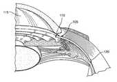
- FIG. 1is a cross-sectional, perspective view of a portion of the eye showing the anterior and posterior chambers of the eye.
- FIG. 2is a cross-sectional view of a human eye.
- FIG. 3Ashows a first embodiment of any eye shunt.
- FIG. 3Bshows a shunt formed of an elongate wick member through which fluid can flow.
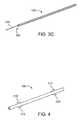
- FIG. 3Cshows a shunt that combines a tube and a wicked member.
- FIG. 4shows the shunt including one or more retention structures.
- FIG. 5shows an exemplary embodiment of a delivery system that can be used to deliver the shunt into the eye.
- FIG. 6Ashows another embodiment of a delivery system.
- FIG. 6Bshows another embodiment of a delivery system.
- FIGS. 6C and 6Dshow the delivery system of FIG. 6B during actuation.
- FIGS. 6E-6Gshow a distal region of the delivery system during various stages of actuation.
- FIG. 6Hshows an enlarged view of an exemplary distal region of an applier of the delivery system.
- FIG. 7shows an enlarged view of an end region of the shunt.
- FIG. 8shows another embodiment of the shunt wherein a plurality of holes are located on the side walls of the shunt.
- FIG. 9Ashows another embodiment of the shunt that includes an elongate portion of fixed size and one or more expansion members.
- FIG. 9Bshows an embodiment of the expansion members that are formed of splayed tines.
- FIG. 10shows another embodiment of the shunt that includes a retaining member located on the proximal end of the shunt.
- FIG. 11shows an embodiment of the shunt that includes one or more slots.
- FIG. 12shows an embodiment of the shunt that includes a distal coil member.
- FIG. 13shows a distal region of an embodiment of the shunt that includes a distal coil member and a sharpened distal end.
- FIG. 14shows a cross-sectional view of the eye and a viewing lens.
- FIG. 15Ashows the delivery system positioned for penetration into the eye.
- FIG. 15Bshows an embodiment wherein the delivery system is connected to an energy source.
- FIG. 16shows an enlarged view of the anterior region of the eye with a portion of the delivery system positioned in the anterior chamber.
- FIG. 17shows the distal tip of the applier positioned within the suprachoroidal space.
- FIG. 18shows a shunt having a skirt.
- FIG. 19shows a shunt that is equipped with a pronged skirt.
- FIG. 20shows the skirted shunt positioned in the eye.
- FIG. 21shows a shunt implanted in the eye so as to provide a fluid pathway between the anterior chamber and the suprachoroidal space.
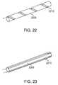
- FIGS. 22 and 23shows shunts that include external fluid flow features.
- FIG. 24 , 25 A, and 25 Bshows a shunt that includes an elongate outer member mounted over a plug member.
- FIG. 26shows an embodiment of the shunt formed of a sponge-like flow member.
- FIG. 27shows a shunt as in FIG. 26 having an internal lumen.
- FIG. 28shows an embodiment of the shunt that includes a pair of anchor members located on opposite ends of the shunt.
- FIG. 29shows an end region of the shunt that includes slices.
- FIG. 30shows an embodiment of the shunt with outer sleeves.
- FIG. 31shows another embodiment of the shunt with sleeves.
- FIG. 32shows another embodiment of the shunt, which has a coiled structure.
- FIGS. 33A and 33B and 34show embodiments of the shunt that include a grasping loop.
- FIG. 35shows an embodiment of an elongate device with a snare that can be positioned inside a shunt.
- FIG. 36shows an embodiment of a spatula-shaped end region of a shunt.
- FIG. 37shows a shunt having an atraumatic tip.
- FIG. 38shows an embodiment wherein the shunt that includes a resilient region.
- FIGS. 39 , 40 A, and 40 Bshow alternate embodiments of the shunt.
- FIG. 41shows an embodiment of the shunt with holes that communicate with an internal lumen.
- FIGS. 42A , 42 B, and 43show embodiments of the shunt that include valved regions.
- FIGS. 44 and 45show embodiments of the shunt that include one or more bulbous elements.
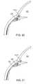
- FIGS. 46 and 47show embodiments of the bulbous element shunt positioned in the suprachoroidal space.
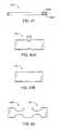
- FIG. 48shows an embodiment of the shunt that includes a bullet-shaped tip member.
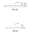
- FIG. 49shows an embodiment of a shunt that mounts over a mandrel.
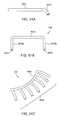
- FIGS. 50 and 51Ashow embodiments of shunts that change shape after removal from a mandrel.
- FIG. 51Bshows another embodiment of a shunt.
- FIG. 51Cshows another embodiment of a shunt.
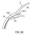
- FIG. 52shows a shunt with a curved proximal region positioned in the eye.
- FIG. 53shows a schematic, front view of the upper region of a patient's face including the two eyes.
- FIGS. 54A and 54Bshow perspective and plan views of an exemplary delivery pathway of the applier and shunt during implantation of the shunt into the eye.
- FIGS. 55A-55Dshow plan and perspective views of a delivery system being inserted into the eye.
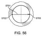
- FIG. 56shows a plan view of an exemplary delivery pathway.
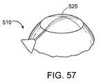
- FIG. 57shows a perspective view of an alternate delivery pathway into the eye.
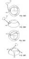
- FIGS. 58A-58Dshow yet another delivery pathway into the eye.
- FIG. 59shows a shunt having an extension sized and positioned such that a proximal end is positioned over a crest of the iris.
- FIG. 60shows a shunt with a curved extension positioned in the eye.
- FIG. 61shows another embodiment wherein the shunt extends through the iris such that the proximal end and the internal lumen of the shunt communicate with the posterior chamber.
- FIGS. 62 and 63show a trans-scleral delivery approach for the shunt.
- FIG. 1is a cross-sectional, perspective view of a portion of the eye showing the anterior and posterior chambers of the eye.
- a shunt 105is positioned inside the eye such that a proximal end 110 is located in the anterior chamber 115 and a distal end 120 is located in the suprachoroidal space (sometimes referred to as the perichoroidal space).
- the shunt 105is illustrated in FIG. 1 as an elongate element having one or more internal lumens through which aqueous humour can flow from the anterior chamber 115 into the suprachoroidal space. Embodiments of the shunt 105 with various structural configurations are described in detail below.
- FIG. 2is a cross-sectional view of a human eye.
- the eyeis generally spherical and is covered on the outside by the sclera S.
- the retina Rlines the inside posterior half of the eye.
- the retinaregisters the light and sends signals to the brain via the optic nerve.
- the bulk of the eyeis filled and supported by the vitreous body, a clear, jelly-like substance.
- the elastic lens Lis located near the front of the eye.
- the lens Lprovides adjustment of focus and is suspended within a capsular bag from the ciliary body CB, which contains the muscles that change the focal length of the lens.
- a volume in front of the lens Lis divided into two by the iris I, which controls the aperture of the lens and the amount of light striking the retina.
- the pupilis a hole in the center of the iris I through which light passes.
- the volume between the iris I and the lens Lis the posterior chamber PC.
- the volume between the iris I and the corneais the anterior chamber AC. Both chambers are filled with a clear liquid known as aqueous humour.
- the ciliary body CBcontinuously forms aqueous humour in the posterior chamber PC by secretion from the blood vessels.
- the aqueous humourflows around the lens L and iris I into the anterior chamber and exits the eye through the trabecular meshwork, a sieve-like structure situated at the corner of the iris I and the wall of the eye (the corner is known as the iridocorneal angle).
- Some of the aqueous humourfilters through the trabecular meshwork into Schlemm's canal, a small channel that drains into the ocular veins. A smaller portion rejoins the venous circulation after passing through the ciliary body and eventually through the sclera (the uveoscleral route).
- Glaucomais a disease wherein the aqueous humor builds up within the eye.
- the ciliary processessecrete aqueous humor, which then passes through the angle between the cornea and the iris.
- Glaucomaappears to be the result of clogging in the trabecular meshwork. The clogging can be caused by the exfoliation of cells or other debris.
- the aqueous humordoes not drain properly from the clogged meshwork, it builds up and causes increased pressure in the eye, particularly on the blood vessels that lead to the optic nerve. The high pressure on the blood vessels can result in death of retinal ganglion cells and eventual blindness.
- Closed angle (acute) glaucomacan occur in people who were born with a narrow angle between the iris and the cornea (the anterior chamber angle). This is more common in people who are farsighted (they see objects in the distance better than those which are close up). The iris can slip forward and suddenly close off the exit of aqueous humor, and a sudden increase in pressure within the eye follows.
- Open angle (chronic) glaucomais by far the most common type of glaucoma.
- the irisdoes not block the drainage angle as it does in acute glaucoma. Instead, the fluid outlet channels within the wall of the eye gradually narrow with time. The disease usually affects both eyes, and over a period of years the consistently elevated pressure slowly damages the optic nerve.
- FIG. 3Ashows a first embodiment of the shunt 105 .
- the shunt 105is an elongate member having a proximal end 110 , a distal end 120 , and a structure that permits fluid (such as aqueous humour) to flow along the length of the shunt such as through the shunt or around the shunt.
- the elongate memberincludes at least one internal lumen 305 having at least one opening for ingress of fluid and at least one opening for egress of fluid.
- the shuntincludes a single opening in the proximal end 110 and a single opening in the distal end 120 that both communicate with the internal lumen 305 .
- the shunt 105can include various arrangements of openings that communicate with the lumen(s), as described below.
- the internal lumen 305serves as a passageway for the flow of aqueous humour through the shunt 105 directly from the anterior chamber to the suprachoroidal space.
- the internal lumen 305can be used to mount the shunt 105 onto a delivery system, as described below.
- the internal lumen 305can also be used as a pathway for flowing irrigation fluid into the eye generally for flushing or to maintain pressure in the anterior chamber, or using the fluid to hydraulically create a dissection plane into or within the suprachoroidal space.
- the shunt 105has a substantially uniform diameter along its entire length, although the diameter of the shunt can vary along its length, as described below.
- the shunt 105is shown as having a circular cross-sectional shape, the shunt can have various cross-sectional shapes (such as an oval or rectangular shape) and can vary in cross-sectional shape moving along its length.
- the cross-sectional shapecan be selected to facilitate easy insertion into the eye.
- the shunt 105can include one or more features that aid in properly positioning the shunt 105 in the eye.
- the shuntcan have one or more visual, tomographic, echogenic, or radiopaque markers 112 that can be used to aid in placement using any of the devices referenced above tuned to its applicable marker system.
- the markersIn using the markers to properly place the implant, the shunt is inserted in the suprachoroidal space, until the marker is aligned with a relevant anatomic structure, for example, visually identifying a marker on the anterior chamber portion of the shunt that aligns with the trabecular meshwork, or scleral spur, such that an appropriate length of the shunt remains in the anterior chamber.
- an echogenic markercan signal the placement of the device within the suprachoroidal space. Any marker can be placed anywhere on the device to provide sensory feedback to the user on real-time placement, confirmation of placement or during patient follow up. Other structural features are described below.
- the shunt 105can also include structural features that aid in anchoring or retaining the implanted shunt 105 in the eye.
- the shunt 105can include one or more retaining or retention structures 410 , such as protrusions, wings, tines, or prongs, that lodge into anatomy to retain the shunt in place.
- the retention structures 410can be deformable or stiff.
- the retention structures 410can be made of various biocompatible materials.
- the retention structures 410can be made from thin 0.001′′ thick polyimide, which is flexible, thin 0.003′′ silicone elastomer which is also flexible, or stainless steel or Nitinol.
- the retention structures 410could be rings of polyimide.
- retention structures 410can be made from other materials.
- the shape of retention structures 410can vary.
- FIG. 4shows the retention structures 410 as barb-shaped with pointed edges of the barbs pointing in opposite directions.
- the retention structures 410can be rectangular, triangular, round, combinations thereof, or other shapes. Additional embodiments of retention structures 410 are described below.
- shunt 105Other anchoring or retaining features can be employed with the shunt 105 .
- one or more hairssuch as human hairs, or synthetic hairs made from polymers, elastomers or metals can be attached to the shunt.
- the hairscancan be glued or thermally bonded to the shunt.
- the hairs, if they are polyimide,can be attached to the shunt by dipping and polymerized by heat and pressure if the dipping material is polyimide.
- the hairscan be crimped to the shunt by rings.
- the shuntcan have through-hole features that the hairs can be threaded through and tied or knotted.
- the hairscan be overmolded onto the shunt body.
- the hairsare positioned relative to the shunt such that at least a portion of the hair extends outwardly from the shunt for anchoring within or against the tissue of the eye.
- Various anchoring and retaining featuresare described herein and it should be appreciated that the features can be implemented in any of the shunt embodiments described herein.
- the retaining featurescan be manufactured by various methods.
- the retaining featurescan be inherent in the raw material from which the shunt is constructed.
- the shuntcan be machined or laser ablated from a unitary rod or block of stock of material with the material subtracted or removed, leaving the retaining features behind.
- the retaining featurescan be manufactured as separate parts and assembled onto the shunt. They can be joined to the shunt by a friction fit or attached with biocompatible adhesives. They can fit into grooves, holes or detents in the body of the shunt to lock them together. If the retaining features are constructed from hairs or sutures, they can be threaded or tied onto the shunt. Alternatively, the retaining features can be overmolded onto the shunt via an injection molding process. Alternatively, the entire shunt and retention features can be injection molded in one step. Alternatively, the retaining features can be formed into the shunt with a post-processing step such as flaring or thermoforming parts of the shunt.
- the shunt 105can be made of various materials, including, for example, polyimide, Nitinol, platinum, stainless steel, molybdenum, or any other suitable polymer, metal, metal alloy, or ceramic biocompatible material or combinations thereof.
- Other materials of manufacture or materials with which the shunt can be coated or manufactured entirelyinclude Silicone, PTFE, ePTFE, differential fluoropolymer, FEP, FEP laminated into nodes of ePTFE, silver coatings (such as via a CVD process), gold, prolene/polyolefins, polypropylene, poly(methyl methacrylate) (PMMA), acrylic, PolyEthylene Terephthalate (PET), Polyethylene (PE), PLLA, and parylene.
- the shunt 105can be reinforced with polymer, Nitinol, or stainless steel braid or coiling or can be a co-extruded or laminated tube with one or more materials that provide acceptable flexibility and hoop strength for adequate lumen support and drainage through the lumen.
- the shuntcan alternately be manufactured of nylon (polyamide), PEEK, polysulfone, polyamideimides (PAI), polyether block amides (Pebax), polyurethanes, thermoplastic elastomers (Kraton, etc), and liquid crystal polymers.
- any of the embodiments of the shunt 105 described hereincan be coated on its inner or outer surface with one or more drugs or other materials, wherein the drug or material maintains the patency of the lumen or encourages in-growth of tissue to assist with retention of the shunt within the eye or to prevent leakage around the shunt.
- the drugcan also be used for disease treatment.
- the shuntcan also be coated on its inner or outer surface with a therapeutic agent, such as a steroid, an antibiotic, an anti-inflammatory agent, an anticoagulant, an antiglaucomatous agent, an anti proliferative, or any combination thereof.
- the drug or therapeutic agentcan be applied in a number of ways as is known in the art.
- the drugcan be embedded in another polymer (nonabsorbable or bioabsorbable) that is coated on the shunt.
- the shuntcan also be coated or layered with a material that expands outward once the shunt has been placed in the eye.
- the expanded materialfills any voids that are positioned around the shunt.
- Such materialsinclude, for example, hydrogels, foams, lyophilized collagen, or any material that gels, swells, or otherwise expands upon contact with body fluids.
- the shuntcan also be covered or coated with a material (such as polyester, ePTFE (also known as GORETEX®), PTFE that provides a surface to promote healing of the shunt into the surrounding tissue.
- a materialsuch as polyester, ePTFE (also known as GORETEX®), PTFE that provides a surface to promote healing of the shunt into the surrounding tissue.
- ePTFEalso known as GORETEX®
- PTFEthat provides a surface to promote healing of the shunt into the surrounding tissue.
- well-known sputtering techniquescan be employed to coat the shunt. Such a low profile coating would accomplish a possible goal of preventing migration while still allowing easy removal if desired.
- the shunt 105is formed of an elongate wick member through which fluid can flow.
- the wick membercan be formed of a single strand of material or can be formed of a plurality of strands that are interconnected, such as in a twisted, braided, or woven fashion, and through or along which fluid can flow.
- the wick member(s)do not necessarily include internal lumens, as flow through the wick member can occur via capillary action.
- certain surface detentscan provide flow lumens between the central body member and the tissue of the suprachoroidal space.
- the shunt 105can include one or more wick members 315 in fluid communication with an internal lumen 305 (or external lumen) of an elongate member. The flow of aqueous humour occurs both through the internal lumen 305 and through or along the wick member 315 .
- the shunthas a length in the range of 0.1′′ to 0.75′′ and an inner diameter for a flow path in the range of 0.002′′ to 0.015′′.
- the inner diameteris 0.012′′, 0.010′′, or 0.008′′.
- a wicking shuntcan have a diameter in the range of 0.002′′ to 0.025′′.
- the fully implanted devicecan create a length of 0.2′′ to 1.0′′, although the length can be outside this range.
- An embodiment of the shuntis 0.250′′ long, 0.012′′ in inner diameter, and 0.015′′ in outer diameter.
- One embodiment of the shuntis 0.300′′ long.
- the shunt 105has a column strength sufficient to permit the shunt 105 to be inserted into suprachoroidal space such that the distal tip of the shunt 105 tunnels through the eye tissue (such as the ciliary body) without structural collapse or structural degradation of the shunt 105 .
- the surface of the inner lumen 305is sufficiently smooth relative to the delivery device (described in detail below) to permit the shunt 105 to slide off of the delivery device during the delivery process.
- the column strengthis sufficient to permit the shunt to tunnel through the eye tissue into the suprachoroidal space without any structural support from an additional structure such as a delivery device.
- the shunt 105can be configured to transition between a first state of reduced size and a second state of expanded size.
- the shunt 105can be in a first state wherein the shunt 105 has a reduced radial size and/or overall length in order to facilitate fitting the shunt through a small portal during delivery.
- the shuntcan then transition to a second state of increased radial size and/or overall length.
- the shuntcan also change cross sectional shape along the length.
- the transition between the first and second statescan be implemented in various manners.
- the shuntcan be manufactured of a material such as Nitinol that deforms in response to temperature variations or a release of a constraining element.
- the shuntcan be self-expanding or self-restricting at various locations along the length.
- the shuntcan be expanded manually, such as through use of an expansion balloon or by passing the shunt along a pre-shaped device, such as a reverse-tapered delivery trocar that increases in diameter.
- the shuntcan be positioned inside a sheath during delivery wherein the sheath maintains the shunt in the first state of reduced size. Upon delivery, the sheath can be removed to permit the shunt to expand in size.
- FIG. 5shows an exemplary delivery system 510 that can be used to deliver the shunt 105 into the eye pursuant to methods described in detail below.
- the delivery system 510includes a handle component 515 that controls a shunt placement mechanism, and a delivery component 520 that removably couples to the shunt 105 for delivery of the shunt 105 into the eye.
- the delivery component 520includes an elongate applier 525 .
- the applier 525has a sharpened distal tip.
- the applier 525is sized to fit through the lumen in the shunt 105 such that the shunt 105 can be mounted on the applier 525 .
- the applier 525can have a cross-sectional shape that complements the cross-sectional shape of the internal lumen of the shunt 105 to facilitate mounting of the shunt onto the applier 525 . It should be appreciated the applier 525 does not have to employ a sharpened distal tip.
- the applier 525can have an atraumatic or blunt distal tip such that it serves as a component for coupling to the shunt, or performing blunt dissection, rather than as a cutting component.
- the delivery component 520also includes a shunt deployment or advancing structure 530 positioned on a proximal end of the applier 525 .
- the advancing structure 530can be an elongated tube that is positioned over the applier 525 .
- the delivery system 510can be actuated to achieve relative, sliding movement between the advancing structure 530 and the applier 525 .
- the advancing structure 520can be moved in the distal direction (as represented by the arrow 532 ), while the applier 525 remains stationary to push or otherwise advance the shunt 105 along the applier 525 for delivery of the shunt 105 into the eye.
- the applier 525withdraws distally into the advancing structure 530 to remove the shunt 105 from the applier 525 , as described below with reference to FIG. 6B .
- both the advancing structure 530 and the applier 525move relative to one another to remove the shunt 105 .
- the applier 525can have a length sufficient to receive a plurality of shunts in an end-to-end series arrangement on the applier 525 .
- multiple shunts 105can be loaded onto the applier 525 and delivered one at a time such that the shunts collectively form an elongated lumen of sufficient length for adequate drainage.
- multiple shuntscan be placed in multiple separate locations within one eye.
- the applier 525 or any portion of the delivery component 520can have an internal lumen that extends along its length for receipt of a guidewire that can be used during delivery of the shunt 105 .
- the internal lumen in the delivery component 520can also be used for the flow of fluid in order to irrigate the eye.
- the internal lumencan be sufficiently large to receive the shunt 105 such that the shunt 105 is mounted inside the applier 525 , rather than over the applier 525 , during delivery.
- the handle component 515 of the delivery system 510can be actuated to control delivery of the shunt 105 .
- the handle component 515includes an applier control 540 that can be actuated to cause the applier 525 to extend in length in the distal direction or to retract in the opposite direction (proximal direction).
- the handle component 515also includes an implant advancing actuator 535 that can be actuated to selectively move the advancing structure 530 along the applier 525 in the proximal or distal direction. In this manner, the advancing structure 530 can be used to push the shunt 105 in the distal direction and off of the applier 525 during delivery, or else to hold the shunt 105 in a fixed location in the eye while the applier 525 is withdrawn.
- the handle component 515can be adapted such that it can be actuated using only a single hand.
- the delivery system 510can include an actuation member that is separate from the handle 515 such that the operator can use a foot to actuate the delivery system 510 .
- a foot pedal or hydraulicscan be coupled to or incorporated within the delivery system 510 to save the use of the physician's hand at the worksite.
- the physiciansimply positions a cannula or delivery system with his or her hands and uses the foot pedal to advance the shunt.
- PCT Publication No. WO06012421which is incorporated herein by reference in its entirety, describes an exemplary hydraulic assist for an ablation catheter with a steerable tip.
- the distal tip of the shunt 105can have a pointed or other type of shape (such as a beveled or blunted shape) on the distal end that facilitates penetration of the shunt 105 through tissue. Exemplary methods for delivering the shunt 105 into the eye are described in detail below.
- the applier 525can be equipped with one or more mechanisms that cause expansion of the shunt 105 .
- the applier 525can include an expandable structure, such as an inflatable sheath, that is mounted over a solid core of the applier 525 .
- the inflatable sheathis positioned at least partially within the internal lumen of the shunt 105 when the shunt 105 is mounted on the applier 525 .
- the inflatable sheathis expanded when the shunt 105 is positioned in the appropriate location in the eye to expand the shunt 105 and cause the shunt 105 to lodge in the location.
- the sheathis then deflated or otherwise reduced in size to permit the applier 525 to be withdrawn from the shunt 105 . Exemplary methods are described below.
- the applier 525can be made of various materials, including, for example, stainless steel and Nitinol.
- the applier 525can be straight (as shown in FIG. 5 ) or the applier 525 can be curved along all or a portion of its length (as shown in FIG. 6A ) in order to facilitate proper placement through the cornea.
- the curvature of the applier 525can vary.
- the applier 525can have a radius of curvature of 3 mm to 50 mm and the curve can cover from 0 degrees to 180 degrees.
- the applier 525has a radius of curvature that corresponds to or complements the radius of curvature of a region of the eye, such as the suprachoroidal space.
- the radius of curvaturecan be around 12 mm.
- the radius of curvaturecan vary moving along the length of the applier 525 . There can also be means to vary the radius of curvature of portions of the applier 525 during placement.
- the appliercan also have a structure that enables or facilitates use of the applier 525 .
- the distal tip of the applier 525can have a shape that facilitates blunt dissection of targeted tissue such as to facilitate dissection into the suprachoroidal space.
- the distal tip of the applier 525can have a flat, shovel, spade, etc. shape, for example.
- FIG. 6Bshows another embodiment of the delivery device 510 .
- the handle component 515includes an actuator comprised of a knob 550 that can slide relative to the handle component 515 .
- the knob 550serves as an actuator that controls relative, sliding movement between the advancing member 530 and the applier 525 .
- the advancing member 530can be fixed relative to the handle component 515 .
- the applier 525is extended outwardly relative to the advancing member 530 .
- Movement of the knob 550such as in the proximal direction, causes the applier 525 to slide proximally into the advancing element 530 as shown in FIG. 6D .
- FIG. 6Eshows the shunt 105 mounted on the applier 525 distal of the advancing structure 530 .
- the knob 550When the knob 550 is actuated, the applier 525 slides in the proximal direction and into the advancing structure 530 , as shown in FIG. 6F .
- the proximal edge of the shunt 105abuts the distal edge of the advancing structure 530 to prevent the shunt 105 from sliding in the proximal direction.
- the applier 525gradually withdraws from the shunt 105 .
- FIG. 6Gthe applier 525 can be fully withdrawn into the advancing structure 530 such that the shunt 105 is released from the applier 525 .
- FIG. 6Hshows an enlarged view of an exemplary distal region 537 of the applier 525 .
- the distal region 537 of the applier 525can be shaped to facilitate an approach into the suprachoroidal space.
- the distal region 537can have a curved contour that compliments the curved contour of the dissection plane, such as the suprachoroidal space.
- At least a portion of the applier 525can be flexible.
- the distal region 537 of the applier 525can be flexible such that it conforms to the shape of the shunt 105 when the shunt 105 is mounted on the distal region 537 .
- the distal region 537can also conform to the shape of the advancing element 530 when the applier 525 is withdrawn into the advancing element 530 .
- the shunt 105can include various types of structures and mechanisms for retaining or otherwise anchoring the position of the shunt 105 in the eye.
- the shunt 105can be equipped with a structure (such as a mesh structure or spray coating) that facilitates endothelial growth of tissue around the shunt for permanent placement of the shunt.
- FIG. 7shows an enlarged view of an end region, such as the distal end region, of the shunt 105 .
- the end regionincludes retaining structures comprised of one or more fenestrations, slits or slots 705 located on the shunt 105 .
- the slots 705are shown arranged in a series along the end region of the shunt 105 , although it should be appreciated that the spatial configuration, size, and angle of the slots 705 can vary.
- the shunt 105 shown in FIG. 7has a distal wall 710 that at least partially encloses the distal end of the internal lumen.
- the distal wall 710can have a slot 705 for fluid flow into and out of the lumen. Alternately, the distal wall 710 can be absent such that an opening is present for the flow of fluid.
- the slotscan operate to allow fluid flow in addition to the central lumen of the shunt 105 .
- the slots 705form edges that interface with surrounding tissue to prevent the shunt 105 from becoming dislodged once implanted in the eye.
- the slots 705form holes that communicate with the internal lumen of the shunt 105 for inflow and outflow of aqueous humour relative to the lumen.
- the proximal end of the shuntcan also be equipped with an arrangement of slots 705 .
- FIG. 8shows another embodiment of the shunt 105 wherein a plurality of holes are located on the side walls of the shunt 105 and interspersed along the length of the shunt 105 .
- the holesfacilitate the flow of fluid into and out of the internal lumen of the shunt 105 .
- the shunt 105can be configured such that it initially does not have any holes. After the shunt 105 is placed in the eye, one or more holes can be formed in the shunt, such as by applying a laser (e.g., a YAG laser) to the shunt 105 or using other means to form the holes.
- a lasere.g., a YAG laser
- Each of the holescan communicate with a separate flow path that extends through the shunt 105 . That is, the shunt 105 can include a plurality of internal lumens wherein each internal lumen communicates with one or more of the holes in side wall of the shunt.
- FIG. 9Ashows another embodiment of the shunt 105 that includes an elongate portion 905 of fixed size and one or more expansion members 910 .
- the elongate portion 905includes an internal lumen and one or more openings for ingress and egress of fluid relative to the lumen.
- the expansion members 910are configured to transition between a first state of reduced size and a second state of expanded or increased size.
- the structure of the expansion members 910can vary.
- each expansion member 910is formed of a plurality of axially-extending rods or tines that are connected at opposed ends. The rods can deform outward along their length to expand the radial size of the expansion member 910 .
- the expansion of the expansion members 910can be implemented in various manners, such as by using an expansion balloon or by manufacturing the expansion members of a material such as Nitinol that deforms or expands in response to temperature variations or a retractable sheath 915 that allows expansion of a shunt formed from a resilient material.
- the expansion memberscan also be biased outward such that they self-expand when unrestrained.
- an embodiment of the expansion members 910are formed of tines that are splayed or fanned outward.
- the tinesare configured to hold tissue of the suprachoroidal space open.
- Either one or both of the expansion members 910can include splayed tines.
- the expansion member 910 acan be as configured in FIG. 9A
- the expansion member 910 bcan be as configured in FIG. 9B (or vice-versa).
- the shuntcan include three or more expansion members.
- the expansion members 910can be biased toward the expanded state such that, when unopposed, the expansion members 910 automatically move toward the expanded state.
- each of the expansion members 910can be positioned within a sheath 915 during delivery, wherein the sheath 915 maintains the expansion members 910 in the reduced-size state.
- the sheath 915is removed from the expansion members to permit the expansion members 910 to self-expand.
- the sheath 915can have a strong hoop and tensile strength to hold the expansion members 910 in an unexpanded state until the shunt 105 in a proper place in the eye.
- the sheath 915is manufactured of PolyEthylene Terephthalate (PET).
- FIG. 9Aincludes a first expansion member 910 a on a distal end of the shunt 105 and a second expansion member 910 b on a proximal end of the shunt 105 .
- the quantity and location of the expansion members 910 on the shuntcan vary.
- the shunt 105can include only a single expansion member 910 on either the proximal end or the distal end, or could include one or more expansion members interspersed along the length of the portion 905 .
- Expansion memberscan be configured in other geometries e.g. latticed, coiled or combinations of each.
- FIG. 10shows another embodiment of the shunt 105 that includes a retaining member 1005 located on the proximal end of the shunt 105 .
- the retaining member 1005has an enlarged size with respect to the remainder of the shunt and has a shape that is configured to prevent the shunt from moving further into the suprachoroidal space after being properly positioned.
- the enlarged shape of the retaining member 1005can lodge against tissue to prevent movement of the shunt 105 into or out of a predetermined location, such as the suprachoroidal space.
- the retaining member 1005 of FIG. 10has a funnel or cone-like shape, although the retaining member 1005 can have various shapes and sizes that are configured to prevent the shunt from moving further into the suprachoroidal space.
- the retaining member 1005can have a plate or flange-like shape.
- the shunt 105 of FIG. 10is tapered moving along its length such that the diameter of the shunt 105 gradually reduces moving in the distal direction.
- the distal directionis represented by the arrow 532 in FIG. 10 .
- the tapered configurationcan facilitate a smooth insertion into the eye.
- the tapercan exist along the entire length of the shunt or it can exist only along one or more regions, such as a distal region.
- the shuntcan have a bulbous section at approximately its midpoint to create an additional means to anchor.
- the bulbous sectioncan be an expandable member or balloon element. Shunts with bulbous sections are described in detail below.
- the shunt 105includes an internal lumen.
- the lumencan have a uniform diameter along the length of the shunt or that can vary in diameter along the length of the shunt.
- the diameter of the internal lumencan taper in a manner that achieves a desired fluid flow rate through the shunt.
- the diameter of the lumencan be varied to regulate fluid flow through the shunt.
- Flow regulationcan also be achieved by variation in size, quantity, and/or position of holes 1010 in the distal region of the shunt 105 , wherein the holes 1010 communicate with the internal lumen.
- the holes 1010can have shapes, sizes, and quantities that are selected to achieve a desired intraocular pressure of the eye as a result of the flow of aqueous humour through the shunt.
- the use of multiple holespermit fluid to flow through the shunt 105 even when one of the holes 1010 is blocked.
- the holes 1010can be positioned so as to align with predetermined anatomical structures of the eye.
- one or more holes 1010can align with the suprachoroidal space to permit the flow of aqueous humour into the suprachoroidal space, while another set of holes 1010 aligns with structures proximal to the suprachoroidal space, such as structures in the ciliary body or the anterior chamber of the eye.
- the shuntcan have visual markers along its length to assist the user in positioning the desired portion of the shunt within the anterior chamber.
- the shunt and delivery systemcan employ alignment marks, tabs, slots or other features that allow the user to know alignment of the shunt with respect to the delivery device.
- FIG. 11shows an embodiment of the shunt 105 that includes one or more slots 1105 that are positioned around the circumference of the shunt.
- the slots 1105provide variations in the shunt structure that permit the shunt to flex during delivery such as to enable proper placement of the shunt 105 from the anterior chamber of the eye to the suprachoroidal space.
- the shunt 105can also be manufactured of a flexible material with or without slots 1105 .
- the shunt 105can have other features that provide flexibility to the shunt.
- the shuntcan be scored or laser cut for flexibility at various locations along the shunt.
- the scorescan be located at various positions along the length of the shunt 105 to provide localized variation in the flexibility of the shunt.
- a distal regioncan have a plurality of scores to provide increased flexibility, while a proximal region includes a reduced number of scores that provide less flexibility than the distal region.
- FIG. 12shows an embodiment of the shunt 105 that includes a distal coil member 1205 .
- the coiled configuration of the coil member 1205provides increased flexibility to the distal region of the shunt 105 to facilitate traction into the suprachoroidal space.
- the coil member 1205can facilitate fluid flow from the internal lumen into the suprachoroidal space.
- the coil member 1205can permit a screwing motion to advance and/or secure the shunt 105 in the eye.
- the distal tip of the shunt 105can have an atraumatic shape, such as a ball shape (as shown in FIG. 12 ).
- the distal tipcan alternately have a sharpened tip and a shape with barbs that retains the shunt in the eye, as shown in FIG. 13 . Any of the features that are described herein as being on the distal tip could also be located on the proximal tip of the shunt.
- the shuntis implanted using the delivery system by accessing the scleral spur to create a low profile dissection in the tissue plane between the choroid and the sclera.
- the shuntis then secured in the eye so that it provides communication between the anterior chamber and the suprachoroidal space.
- FIG. 14shows a cross-sectional view of the eye.
- a viewing lens 1405(such as a gonioscopy lens represented schematically in FIG. 14 ) is positioned adjacent the cornea.
- the viewing lens 1405enables viewing of internal regions of the eye, such as the scleral spur and scleral junction, from a location in front of the eye.
- the viewing lens 1405can optionally include one or more guide channels 1410 that are sized to receive the delivery portion 520 of the delivery device 510 . It should be appreciated that the locations and orientations of the guide channels 1410 in FIG. 14 are merely exemplary and that the actual locations and orientations can vary depending on the angle and location where the shunt 105 is to be delivered.
- the viewing lens 1405can have a shape or cutout that permits the surgeon to use the viewing lens 1405 in a manner that does not cover or impede access to the corneal incision. Further, the viewing lens can act as a guide through which a delivery device 510 can be placed to predetermine the path of the device as it is inserted through the cornea.
- An endoscopecan also be used during delivery to aid in visualization.
- a twenty-one to twenty-five gauge endoscopecan be coupled to the shunt during delivery such as by mounting the endoscope along the side of the shunt or by mounting the endoscope coaxially within the shunt.
- Ultrasonic guidancecan be used as well using high resolution bio-microscopy, OCT and the like.
- a small endoscopecan be inserted though another limbal incision in the eye to image the tissue during the procedure.
- one or more shunts 105are mounted on the delivery device 510 for delivery into the eye.
- at least one shunt 105can be mounted over the applier 525 or can be mounted within the applier 525 .
- the eyecan be viewed through the viewing lens 1405 or other viewing means such as is described above, in order to ascertain the location where the shunt 105 is to be delivered.
- At least one goalis to deliver the shunt 105 in the eye so that it is positioned such that the internal lumen of the shunt provides a fluid pathway between the anterior chamber and the suprachoroidal space.
- the internal lumenis positioned such that at least one ingress to the lumen communicates with the anterior chamber and at least one egress communicates with the suprachoroidal space.
- the wick membercan communicate with both the anterior chamber and the suprachoroidal space.
- the tube member and wick membercan be combined.
- the internal lumencan be open into the anterior chamber and be open at least partially into the suprachoroidal space, while the wick member extends further into the suprachoroidal space.
- the delivery device 510is positioned such that the distal tip of the applier 525 or the shunt 105 itself can penetrate through the cornea.
- an incisionis made through the eye, such as within the limbus of the cornea.
- the incisionis very close to the limbus, such as either at the level of the limbus or within 2 mm of the limbus in the clear cornea.
- the applier 525can be used to make the incision or a separate cutting device can be used.
- a knife-tipped device or diamond knifecan be used to initially enter the cornea.
- a second device with a spatula tipcan then be advanced over the knife tip wherein the plane of the spatula is positioned to coincide with the dissection plane.
- the spatula-shaped tipcan be inserted into the suprachoroidal space with minimal trauma to the eye tissue.
- the incisionhas a size that is sufficient to permit passage of the shunt therethrough.
- the incisioncan be sized to permit passage of only the shunt without any additional devices, or be sized to permit passage of the shunt in addition to additional devices, such as the delivery device or an imaging device.
- the incisionis about 1 mm in size.
- the incisionis no greater than about 2.85 mm in size.
- the incisionis no greater than about 2.85 mm and is greater than about 1.5 mm. It has been observed that an incision of up to 2.85 mm is a self-sealing incision.
- the drawingis not to scale and the viewing lens 1405 is not shown in FIG.
- the applier 525can approach the suprachoroidal space from the same side of the anterior chamber as the deployment location such that the applier does not have to be advanced across the iris. Alternately, the applier can approach the location from across the anterior chamber such that the applier is advanced across the iris and/or the anterior chamber. The applier 525 can approach the eye and the suprachoroidal space along a variety of pathways. Various pathways for approaching the eye and deploying the shunt are described in detail below.
- the applier 525is advanced through the cornea and the anterior chamber.
- the applieris advanced along a pathway that enables the shunt to be delivered from the anterior chamber into the suprachoroidal space.
- the appliertravels along a pathway that is toward the scleral spur such that the applier crosses through the scleral spur on the way to the suprachoroidal space.
- the applier 525can be pre-shaped, steerable, articulating, or shapeable in a manner that facilitates the applier approaching the suprachoroidal space along a proper angle or pathway.
- a guidewirecan also be used to guide the applier or the shunt over the guidewire to the proper location in the eye.
- the guidewirecan be looped at a distal end to assist in making suprachoroidal dissection. Once the shunt is properly in place, the loop can be released. If the shunt needs to be removed prior to releasing the loop, the guidewire loop can act as a retrieval mechanism.
- the loopcan be larger than the distal lumen opening of the shunt such that when the guidewire is pulled back, the loop pulls the shunt along with it.
- the guidewirecan be left in place even after the applier is removed. This enables the user to repeatedly access the site via the guidewire without having to relocate the site in the eye.
- a cannulacan be used to create an access pathway to the delivery site.
- the delivery toolcan then be placed through the cannula.
- the cannulacan remain fixed in place with the viewing lens, and the end of the delivery device can be articulated or steerable such that multiple shunts can be placed from one access site.
- an infusion cannula from Dutch Ophthalmic Research Center(D.O.R.C.) can be used, in particular models that allow for continuous infusion and aspiration to maintain a sufficient working area within the anterior chamber.
- the distal tip of the applier 525can be sharp and can also be tapered to facilitate a smooth penetration through the cornea.
- the distal tip of the shunt 105can also be sharp.
- the tip of the applier devicecan be connected to an energy source ES, to allow energy to be delivered to the tip of the applier body to assist in creating the initial corneal stick, and in addition facilitating entry into the suprachoroidal space through the scleral spur.
- ESenergy source
- FIG. 15Bonly the distalmost tip is exposed to apply energy to the tissue, and the remaining shaft of the applier is insulated such as with a sleeve made of insulation material.
- Energy delivery wiresare attaching to the applier shaft (such as via the handle) to energize the tip portion, and such wires are also connected to an energy delivery source ES and any required grounding pad.
- the energy that can be delivered to facilitate the procedurecan be RF energy, laser energy, resistive heat energy or ultrasonic energy.
- An energy delivery system for medical usesuch as those produced by Sachrtech Research (Mountain View, Calif.) can be employed, for example, to apply RF energy to the tip of the applier.
- FIG. 16shows an enlarged view of the anterior region of the eye showing the anterior chamber AC, the cornea C, the iris I, the sclera S, and the choroid CH.
- the suprachoroidal spaceis at the junction between the sclera and the choroid.
- the shunt 105which is mounted on the applier 525 , is shown approaching the suprachoroidal space from the anterior chamber.
- the distal tip of the applier 525moves along a pathway such that the distal tip is positioned at the scleral spur with the curve of the applier 525 aiming the distal tip toward the suprachoroidal space.
- the applier 525 and/or the shunt 105can have a radius of curvature that conforms to the radius of curvature of the suprachoroidal space.
- the surgeoncan rotate or reposition the handle of the delivery device in order to obtain a proper approach trajectory for the distal tip of the applier, as described in further detail below.
- the scleral spuris an anatomic landmark on the wall of the angle of the eye.
- the scleral spuris above the level of the iris but below the level of the trabecular meshwork. In some eyes, the scleral spur can be masked by the lower band of the pigmented trabecular meshwork and be directly behind it.
- the applier 525With the applier 525 positioned for approach, the applier 525 is then advanced further into the eye such that the distal tip of the applier and/or the shunt penetrates the scleral spur. The penetration through the scleral spur can be accomplished in various manners.
- a sharpened distal tip of the applier or the shunt puncturespenetrates, dissects, pierces or otherwise passes through the scleral spur toward the suprachoroidal space.
- the crossing of the scleral spur or any other tissuecan be aided such as by applying energy to the scleral spur or the tissue via the distal tip of the applier 525 .
- the means of applying energycan vary and can include mechanical energy, such as by creating a frictional force to generate heat at the scleral spur. Other types of energy can be used, such as RF laser, electrical, etc.
- the applier 525is continuously advanced into the eye, via the trabecular meshwork and the ciliary body, until the distal tip is located at or near the suprachoroidal space such that a first portion of the shunt 105 is positioned within the suprachoroidal space and a second portion is positioned within the anterior chamber. In one embodiment, at least 1 mm to 2 mm of the shunt (along the length) remains in the anterior chamber.
- FIG. 17shows the distal tip of the applier 525 positioned within the suprachoroidal space SS. For clarity of illustration, FIG. 17 does not show the shunt mounted on the applier, although the shunt 525 is mounted on the applier during delivery. As the applier 525 advances through tissue, the distal tip causes the sclera to peel away or otherwise separate from the choroid to expose the suprachoroidal space.
- One method of approachis to advance the applier 525 through the ciliary body as it approaches the suprachoroidal space.
- the tissue of the sclerais structurally more tough than the ciliary body.
- the scleral tissueprovides an increased resistance to passage of the applier 525 therethrough.
- the surgeonwill detect an increase in resistance to passage when the distal tip of the applier passes through the ciliary body and reaches the sclera. This can serve as an indication that the distal tip of the applier has reached the suprachoroidal space.
- the distal region of the applier 525 or the shuntcan have a shape, such as a spade shape or a blunt end, that is configured to facilitate creating a dissection plan between the choroid and the sclera and positioning of the distal region of the applier in the suprachoroidal space.
- This thickness of this dissection planeis approximately the same as the size of the device being placed.
- the distal regioncan be flexible or looped to allow for preferential movement into the space between the sclera and choroid.
- the delivery device 510 and/or the shunt 105can be equipped with navigational aides, such as radiopaque markers, or means to enable ultrasonic visualization that assist in proper positioning of the applier and shunt in the eye.
- navigational aidessuch as radiopaque markers
- the shunt 105is advanced off of the applier 525 , such as by actuating the implant advancing actuator 535 to move the advancing structure 530 ( FIG. 5 ) so as to push the shunt 105 off of the applier into proper placement in the eye.
- the shunt 105can be deployed off of the applier in various manners.
- the shuntcan be pushed off the applier by moving the advancing structure 530 (shown in FIGS. 5-6G ) in the distal direction.
- the advancing structure 530remains stationary and the applier 525 is withdrawn in the proximal direction as was described above with reference to FIGS. 6E-6G .
- This can methodcan be advantageous as the shunt remains stationary during dismount from the applier 525 rather than being moved during dismount.
- the shuntcan be properly positioned while still on the applier 525 .
- the applieris distally advanced into the suprachoroidal space while the shunt remains stationary against the advancing structure 530 .
- the advancing structureis then moved distally to push the shunt along the applier.
- the applieris then withdrawn into the advancing structure to uncouple the shunt from the applier.
- the shuntcan include structural features that assist in proper placement of the shunt, such as to ensure that the shunt 105 is not advanced any further than necessary into the eye.
- the shunt 105can include a structure, such as the proximal retaining member 1005 (shown in FIG. 10 ), that abuts the scleral spur or another tissue structure to prevent further movement of the shunt into the eye.
- FIG. 18shows a shunt 105 that is equipped with a skirt 1805
- FIG. 19shows a shunt that is equipped with a pronged skirt 1810 . As shown in FIG.
- the skirt 1810 or 1805abuts and anchors into the ciliary body to prevent the shunt 105 from being advanced any further into the eye.
- These featurescan further serve to prevent leakage of fluid around the outside of the shunt.
- hypotonialow pressure
- Concern for excess flow and resultant hypotonycan be a major reason why previous efforts have focused on placing shunts through a scleral incision, so the sclera would surround at least a portion of the shunt to prevent flow around the shunt. Therefore, these means for preventing flow around the outside of the shunt can prove essential in enabling placement of a shunt directly from the anterior chamber to the suprachoroidal space without risk of hypotonia.
- FIG. 21shows the shunt 105 implanted in the eye so as to provide a fluid pathway between the anterior chamber AC and the suprachoroidal space SS.
- the shunt 105was implanted by “tunneling” the shunt toward the suprachoroidal space. That is, as the shunt is advanced toward the suprachoroidal space, the distal tip of the applier and/or the shunt penetrates the tissue and forms a tunnel through the eye tissue, initially the ciliary body. This differs from a procedure where the shunt is lowered into the eye via a scleral flap that is cut and folded back for access to the implant location. In such a procedure, the implanted shunt is positioned within a cavity that was formed by the folded-back flap.
- the shunt 105is substantially enclosed or surrounded by eye tissue in the region between the anterior chamber and the suprachoroidal space. It also differs from the procedure known as cyclodialysis, that in some cases entirely disinserts the ciliary body from the scleral spur to relieve the pressure in the anterior chamber, because essentially a puncture is made and the shunt device that is placed, is left in the position of the puncture.
- FIG. 21shows only a single shunt 105 , it should be appreciated that multiple shunts can be implanted in the eye.
- the shuntscan be implanted end-to-end to form a single, elongate fluid pathway or a plurality of shunts can be positioned side-by side or spaced around the circumference of the anterior chamber to form multiple fluid pathways.
- a single shuntcan be implanted in an initial procedure and additional shunts implanted in one or more subsequent procedures as needed to establish or maintain optimal anterior chamber pressure.
- shuntsit is not necessary that all of the shunts (or all openings in a shunt) be initially patent. This will allow the drainage of aqueous humour to be initiated in a controlled manner by selectively opening additional shunts over a period of time. Over time, additional shunts can be activated (i.e., opened), such as by the insertion of a stylet or other needle-type device, such as during an office visit. The shunts can also be opened or re-opened (if a shunt becomes blocked after implantation) in various manners, such as using a photochemical, laser, RF, ultrasound, or thermal procedure, or combinations thereof.
- the shuntcan have a single hole or multiple holes along its proximal end or distal end, one or more of which are initially covered by a second tube or other material. Applying light or other energy to the tube could cause the holes to open or could cause the tube to shrink longitudinally, exposing additional openings to increase flow.
- the outer diameter of the shunt or the diameter of the internal lumencan be varied by shrinking or enlarging the shunt using thermal, light, or photochemical activation.
- the shuntcan be initially relatively long and thin. Applying energy or other activation to the shunt could cause it to become shorter and/or larger in diameter, increasing its flow rate.
- the dissection formed by the shuntcan cause a leak between the anterior chamber and the suprachoroidal space.
- the leakcan be filled or otherwise plugged with a material (such as a foam or adhesive) or a structure (such as a gasket) that prevents leaking.
- a spacer structure 2110can optionally be located on the proximal end of the shunt 105 .
- the spacer structure 2110is a structure that extends outwardly from the shunt 105 to prevent blockage of the proximal end of the shunt 105 .
- the structure 2110can also facilitates grasping the shunt in the event it is necessary to remove the shunt.
- the shunt 105is not positioned on the applier 525 as the applier is advanced into the eye.
- the handle component 515 of the delivery instrumentcan be detached from the proximal end of the applier after the applier has been properly positioned in the eye.
- the shunt 105is then threaded over the applier, from the proximal end to the distal end, toward the delivery site.
- a guide passagewayis formed in the eye prior to advancing the applier through the eye.
- the applieris then advanced through the previously formed passageway rather than using the applier to tunnel through the eye.
- the passagewaycan be formed in various manners, such as by using an energy source or phacoemulsification equipment to form the passageway.
- FIG. 22shows a shunt 105 that includes an elongate core member 2205 that has one or more external fluid flow features, such as flow channels 2210 , located on its outer surface.
- the flow channel(s) 2210define at least one passageway for the flow of aqueous humour along the length of the shunt 105 .
- the configuration of the flow channel(s) 2210can vary. In the embodiment of FIG. 22 , a single flow channel 2210 having a helical or spiral configuration is located on the outer surface of the core member 2205 .
- the core 2205can also include multiple spiral flow channels.
- FIG. 22shows a shunt 105 that includes an elongate core member 2205 that has one or more external fluid flow features, such as flow channels 2210 , located on its outer surface.
- the flow channel(s) 2210define at least one passageway for the flow of aqueous humour along the length of the shunt 105 .
- the configuration of the flow channel(s) 2210
- the shunt 105can also include just a single straight flow channel or can include a combination of straight flow channels and flow channels of various curvilinear configurations.
- the core 2205can be a solid piece of material that does not have an internal lumen.
- a solid core 2205can form a strong structure and can create a reliable flow path with a reduced risk of structural collapse or tissue ingrowth in the lumen.
- the external flow channelscan be combined with an internal lumen that extends through the core 2205 . If the core 2205 is solid without an internal lumen, then it can be delivered into the eye through a delivery lumen of a delivery device, such as through an applier. If the core 2205 includes an internal lumen, then the core can be delivered into the eye mounted over a delivery device, such as over an elongate applier.
- the core 2205can be manufactured in various ways.
- the core 2205can be molded or can be extruded, such as from a biocompatible material or any of the materials described herein.
- the core 2205can also be formed of a combination of different materials or can be co-extruded.
- FIG. 24shows a shunt 105 that includes an elongate outer member 2405 , such as a stent, mounted over a plug member 2410 .
- an elongate outer member 2405such as a stent
- the plug member 2410degrades over time, while the outer member 2405 does not degrade.
- the outer member 2405remains in the eye to maintain a patent passageway between the anterior chamber and the suprachoroidal space.
- the outer member 2405can be solid (such as an elongate tube) or it can be a mesh.
- the outer member 2405can be integrally formed with the plug member 2410 or it can be embedded in varying degrees within the plug member to control the rate of degradation.
- the degradation of the plug 2410can be configured in various manners.
- the rate of degradation of the plugcan be based on the intraocular pressure such that the degradation rate increases as the intraocular pressure increases.
- a higher intraocular pressureresults in a greater rate of plug degradation than a lower intraocular pressure.
- the rate of degradation of the plugcan slow as the intraocular pressure approaches a predetermined value.
- An exemplary way of implementing such a featureis to include an internal lumen 2510 in the plug 2410 , as shown in FIG. 25A .
- the lumen 2510In an initial state, the lumen 2510 has diameter of a reduced size such that a low level of aqueous humour flows through the lumen.
- the initial statecan correspond to the plug being exposed to an initially-high intraocular pressure.
- the high intraocular pressurecauses the plug 2410 to degrade such that the size of the lumen increases.
- the level of aqueous humour flow through the lumenalso increases, which results in a reduction in intraocular pressure and a reduction in the rate of degradation of the plug.
- the stent 2405does not include an internal member.
- a stent 2405is implanted into the eye in a manner that maintains an opening between the suprachoroidal space and the anterior chamber.
- the stent 2405can be a self-expanding or balloon expanding stent that is expanded after it is positioned within the eye.
- the stent 2405can be for example a braided or laser cut stent made of stainless steel or Nitinol.
- the shuntcan also be manufactured of a material that is absorbed into the eye tissue after placement in the eye. Once absorbed, a space remains where the shunt was previously located.
- the shuntcan be manufactured of a complex carbohydrate or a collagen that is non-inflammatory.
- the shuntis covered with or filled with a material that absorbed into the eye over time such as to prevent hypotony or to prevent a clot forming within the tube.
- biodegradable polymersincluding: hydroxyaliphatic carboxylic acids, either homo- or copolymers, such as polylactic acid, polyglycolic acid, polylactic glycolic acid; polysaccharides such as cellulose or cellulose derivatives such as ethyl cellulose, cross-linked or uncross-linked sodium carboxymethyl cellulose, sodium carboxymethylcellulose starch, cellulose ethers, cellulose esters such as cellulose acetate, cellulose acetate phthallate, hydroxypropylmethyl cellulose phthallate and calcium alginate, polypropylene, polybutyrates, polycarbonate, acrylate polymers such as polymethacrylates, polyanhydrides, polyvalerates, polycaprolactones such as poly- ⁇ -caprolactone, polydimethylsiloxane, polyamides, polyvinylpyrollidone, polyvinylalcohol phthallate, waxe
- hydroxyaliphatic carboxylic acidssuch as polylactic acid, polyglycolic acid, polylactic
- FIG. 26shows another embodiment of the shunt that is formed of a sponge-like flow member 2610 that is made of a porous material, such as polyester material.
- the porous nature of the flow member 2610forms one or more fluid pathways for the flow of aqueous humour through the flow member.
- the flow member 2610can be formed of a material that can be pierced along its length by a wire or other structure.
- the piercingforms an internal lumen 2710 ( FIG. 27 ) through which aqueous humour can flow.
- the internal lumen 2710can be formed in the situation where it is desired to increase the flow of aqueous humour through the flow member.
- FIG. 28shows another embodiment of the shunt 105 that includes a pair of anchor members 3305 located on opposite ends of the shunt.
- the anchor members 3305are sized and shaped to engage the eye tissue to retain the shunt 105 in a fixed or substantially fixed position within the eye.
- the shunt 3305includes an elongated central region on which are disposed one or more tines or teeth 3310 that are adapted to anchor with the eye.
- the anchor members 3305 and the teeth 3310extend outwardly from the shunt 105 to define a space 3315 disposed along at least one side of the shunt 105 when the shunt 105 is positioned in the eye.
- the teethcan be oriented to extend at least partially into the trabecular meshwork such that the teeth form flow pathways into Schlemm's canal.
- the teeth 3310can be manufactured of various materials including silver or coated with silver. Silver is a material that prohibits growth of surrounding tissue such that a space is retained around the shunt.
- FIG. 29shows an end region (distal and/or proximal) of the shunt 105 that includes slices that extend generally along the longitudinal direction of the shunt.
- the orientation of the slicescan vary.
- the slicescan extend longitudinally such that the slices define a plurality of longitudinally-extending teeth that can interact with eye tissue to resist migration of the shunt 105 .
- the slicescan also be oriented transverse to the longitudinal axis of the shunt.
- the end regioncan be flared outward to provide further resistance to migration.
- one or more sleeves 3405are positioned over the outer surface of the shunt 105 .
- the sleeves 3405can be interspersed at various locations along the length of the shunt 105 .
- a first sleeve 3405is located on a distal region of the shunt 105 and a second sleeve 3405 is located on a proximal region of the shunt 105 .
- More than two sleevescan be positioned on the shunt.
- the sleeves 3405have an inner diameter that permits the sleeves to be fixedly mounted over the shunt.
- the outer diameter of the sleeveis larger than the outer diameter of the shunt such that the sleeves form a raised surface on the shunt.
- the sleeves 3405can be annular such that the sleeves have an internal lumen that fits entirely around the circumference of the shunt. Alternately, the sleeves 3405 are non-annular strips of material that are positioned on the shunt such that they cover only a portion of the circumference of the shunt.
- the outer surface of the shuntcan include grooves that are machined or molded into the outer surface.
- the groovescan be a series of annular grooves or a single corkscrew groove that extends along the length of the shunt.
- the groovesfunction to form alternating raised and lowered surfaces on the shunt.
- the shuntcould also include pits or pockmarks on the outer surface.
- the sleeves 3405can have a smooth outer surface, an undulating outer surface, or can include one or more slices that can be oriented at various angles relative to the longitudinal axis of the shunt 105 .
- the slicesform teeth in the sleeves 3405 to resist migration of the shunt.
- the sliced teethcan be biased outward such that the teeth flare outward and engage adjacent tissue to prevent movement in either the proximal or distal direction.
- any of the sleevescan also act as a marker to show the physician the proper shunt length to be inserted into the eye.
- one or more printed markerscan be formed on the shunt outer wall or on the delivery device.
- the markerscan be BaSO 4 markers embedded in the shunt material wall wherein the markers are made from an extruded polymer compounded with this radiopaque substance in the region of the desired radiopacity.
- the markerscan be laser printed or etched on the shunt device to show the amount of shunt deployed in the suprachoroidal space, or the amount by which the shunt device should be allowed to protrude into the anterior chamber.
- the sleevescan be manufactured of various materials. In one embodiment, at least one of the sleeves is made of an anti-microbial silver material.
- FIG. 31shows another embodiment of the shunt 105 with sleeves 3605 disposed on proximal and distal ends of the shunt.
- the sleeves 3605have slices that form arcs.
- the slicescan be straight or they can be curvilinear.
- the sliceswill not interfere with fluid flow through the lumen of the shunt.
- an ingrowth of tissue into the slicescan result.
- Such an ingrowthcan interfere with the flow of fluid through the shunt's internal lumen.
- the sleevespermit the use of slices that do not interfere with the internal lumen of the shunt.
- the slices on the sleevescreate retention means on both ends of the shunt.
- the slicesare biased toward each other so that micromotion of the shunt is prevented.
- the slicesbegin to extend axially from the longitudinal axis of the inner lumen causing a restriction of movement of the shunt in either direction.
- FIG. 32shows yet another embodiment of the shunt 105 .
- a retention structuresuch as a coil 3705
- the coil 3705can be formed of a wire that is wrapped around the outer surface of the shunt.
- the coil 3705functions to retain the shunt 105 within the eye.
- the coil 3705can also be sized and shaped such that it forms a conduit or flow path that directs fluid to flow along the outside of the shunt.
- the retention structureneed not be coil shaped but can rather have various shapes and sizes adapted to retain the shunt in place.
- the retention structurecan be a straight wire that extends along the length of the shunt and that is raised relative to the outer surface of the shunt.
- the wirecan have various dimensions. In one embodiment, the wire has a diameter of 0.0005 inch.
- the removal or repositioning structurecan be any structure on the shunt that can be grasped in order to move or remove the shunt.
- the removal structurecan be an enlarged region, a raised region, or a region of reduced diameter that provides a location that can be grasped by a removal tool.
- the retention elements described abovecan also serve as a grasping element for removal or moving of the shunt.
- FIG. 33Ashows an embodiment of the shunt 105 that includes a grasping loop 3805 on the proximal end of the shunt.
- the grasping loop 3805is shaped such that it can be grasped by a removal tool or a repositioning tool.
- the grasping loop 3805can be connected to a coil member 3810 that extends entirely or partially along the length of the shunt 105 such that when the grasping loop is pulled, the shunt undergoes a radial reduction in size, as shown in FIG. 33B .
- the shuntcan also include outer thread structures that permit the shunt to be screwed into the suprachoroidal space by rotating the shunt in one direction and then screwed out by rotating in an opposite direction. The threads can grasp onto the surrounding tissue to provide counter traction when the grasping loop 3805 is pulled.
- the shunt 105can also be formed of a braided shaft with a distal grasping loop 3805 , as shown in FIG. 34 .
- FIG. 35shows another embodiment of an elongate device 4002 with a snare 4005 located on a proximal end.
- the device 4002can be positioned within a lumen of the shunt such that the snare 4005 is compressed within the lumen.
- the device 4002is pulled partially out of the lumen such that the snare 4005 expands to form a loop that can be grasped by a removal or repositioning tool.
- the shunt 105includes a distal region 4105 that is flat and thin so as to have a spatula-like shape.
- the flat and thin configuration of the shuntis adapted to facilitate penetration of the eye and to facilitate peeling of the choroid from the sclera and positioning of the distal region of the applier in the suprachoroidal space.
- the shuntincludes an internal lumen for the passage of a guidewire or through which fluid or visco-elastic substance(s) can be passed to assist dissection or visualization.
- a fiber opticcan also be passed through the lumen to assist direct visualization of the treatment region as desired during placement or repositioning of the shunts.
- the shunt 105can be shaped or otherwise configured so as to minimize the risk of trauma to the eye during delivery or during micromotion of the shunt after the shunt has been delivered.
- any region of the shuntcan have an atraumatic shape or can be manufactured of or coated with a soft material.
- an atraumatic tip 4205is located on the proximal region of the shunt 105 .
- the tip 4205can be shaped in an atraumatic manner, such as by having a rounded end.
- the tip 4205can be manufactured of a material that is softer than the remainder of the shunt or can be manufactured of the same material.
- the atraumatic tip 4205is adapted to protect against damage to the cornea in the event of corneal contact or micromotion of the shunt.
- at least a portion of the shuntincludes a silicone sleeve that at least partially covers the outer surface of the shunt.
- the silicone sleevecan be formed by dipping the shunt into a silicone solution.
- FIG. 38shows another embodiment wherein the shunt 105 includes a resilient region 4305 .
- the resilient regioncan be formed in various manners.
- the resilient regionis formed by either a reinforced region of silicone tube or by a separate resilient element such as a spring.
- the resilient region 4305is corrugated to provide flexibility.
- the springcan be formed of various materials, including polyimide and stainless steel. Any of the embodiments of the shunt described herein can include a resilient region along a portion of its length or can be resilient along its entire length.
- the shuntcan be flexible along its entire length, can have a predetermined stiffness along its entire length or can have a stiffness that varies along its length.
- FIG. 39shows another embodiment of a shunt 105 that does not have an internal lumen.
- the shunt 105has a plurality of extensions 4405 that extend radially outward from a central core.
- the extensions 4405define elongated grooves that extend along the length of the shunt.
- the elongated groovesserve as flow pathways to guide fluid flow along the length of the shunt.
- the embodiment of FIG. 39has four extensions although the quantity of extensions can vary.
- a material, such as silvercan be positioned or coated within the grooves to keep the channels open and to provide increased distribution area for fluid flow. As mentioned, silver serves to inhibit or prevent tissue growth.
- the peripheral edges of the extensions 4405can have grooves or other structures that are adapted to retain or anchor the shunt within the eye.
- the shunt 105has extensions 4405 and a central core with an internal lumen 4407 that can be used to mount the shunt on a delivery device.
- the central lumen 4407can also be used for the flow of fluid through the shunt.
- the shuntcan include features that are adapted to modify or enhance the flow of fluid through or along the shunt, such as after the shunt has been placed in the eye.
- the shunt 105has one or more holes that 4605 that communicate with the internal lumen.
- the holesare initially plugged with a material such that flow cannot occur through the holes.
- the holescan be unplugged, such as by inserting an instrument through the holes or applying energy to the location where the holes are to be formed.
- the holescan also unplug automatically by plugging the holes with a material that degrades upon placement in the eye or that degrades after a period of time.
- FIG. 42Ashows a cross-sectional view of a portion of another embodiment of the shunt 105 .
- the shunt 105includes a narrowed region 4705 such that the internal lumen 4710 is at least partially blocked in the narrowed region 4705 .
- the narrowed region 4705can be opened or expanded at a desired time, such as through applying heat to the narrowed region 4705 to cause the narrowed region to expand such that the internal lumen is no longer blocked.
- the regioncan then be narrowed again by further application of heat if desired.
- the narrowed regioncan also be opened and closed by tying a biodegradable band or suture around the narrowed region. The sutures can erode over a time period so that the narrowed region gradually opens over time.
- FIG. 43shows another embodiment of the shunt 105 that includes one or more valved regions 4907 along the length of the shunt.
- the valved regions 4907serve to regulate the flow of fluid through the internal lumen.
- Each of the valve regions 4907can include a separate valve structure or can be shaped to regulate fluid flow.
- the valved regionscan have an expanded size that permits more fluid flow or can have a reduced size that limits fluid flow.
- the valved regionscan be colored so as to respond to different colors of laser light depending on a desired result.
- FIG. 44shows an embodiment of the shunt 105 that includes a bulbous element 4905 that is radially larger than the remainder of the shunt.
- the bulbous element 4905can be fixed in the enlarged state or it can be adapted to transition from a reduced-size state to the enlarged-size state.
- the bulbous element 4905can be an expandable balloon or it can be an expansion members 910 such as was described above in FIG. 9A .
- the bulbous element 4905can include holes that communicate with the internal lumen of the shunt 105 to permit ingress and egress of fluid.
- FIG. 45shows another embodiment of the shunt 105 wherein the bulbous element 4905 is located between the proximal and distal ends of the shunt 105 .
- the shunt 105includes a central bulbous element 4905 with proximal and distal regions of reduced radial size relative to the bulbous element.
- the shunt 105can also include a plurality of bulbous elements that are interspersed along the length of the shunt.
- FIGS. 46 and 47show two embodiments of the bulbous element shunt positioned in the suprachoroidal space SS.
- the shunt 105is positioned such that a proximal end communicates with the anterior chamber AC and the bulbous element 4905 is positioned in the suprachoroidal space.
- the enlarged bulbous region 4905forms a space or “lake” for accumulation of fluid within the suprachoroidal space.
- the lakeis contained entirely within the suprachoroidal space and enclosed by tissue, the lake is not prone to infection and other complications.
- the lakecan also be formed using an embodiment of the shunt that does not have a bulbous element.
- a fluidcan be flowed into the suprachoroidal space through the internal lumen of the shunt. The fluid fills accumulates within the suprachoroidal space to form the lake.
- the lakeis formed via hydro-dissection.
- a delivery cannulacan be positioned in the eye such that fluid can be flowed into the suprachoroidal space via the cannula.
- the fluidis flowed into the eye with a pressure sufficient to form a dissection plane within the suprachoroidal space.
- the fluidcan then accumulate within the suprachoroidal space so as to form a lake.
- FIG. 48shows an embodiment of the shunt 105 that includes a distal tip member 5305 that is integrally formed with the shunt.
- the tip member 5305has a shape that is adapted to facilitate dissection into the suprachoroidal space.
- the tip member 5305can be “bullet” shaped in that the diameter of the tip member 5305 gradually reduces moving along the distal direction.
- the tip member 5305can include one or more holes that communicate with the internal lumen of the shunt. Alternately, the tip member 5305 can be without holes and holes can be placed on the side of the shunt 105 .
- the tip member 5305can be manufactured of various materials, including stainless steel.
- FIG. 49shows an embodiment of a shunt 105 that mounts over a mandrel 5405 , which can be a portion of the applier 525 such that the mandrel 5405 can be incorporated into the delivery system.
- the shunt 105is adapted to conform to the shape of the mandrel 5405 when it is mounted on the mandrel, such as during delivery of the shunt 105 .
- the shunt 105transitions to a different shape.
- the shunt 105can be at least partially manufactured of a shape-memory material to accomplish the change in shape.
- one or more Nitinol ringsare disposed on the shunt wherein the rings undergo a shape change to induce the shunt to transition in shape.
- a Nitinol wirecan also be threaded along the length of the shunt to induce the shape change.
- the shunt 105can include a proximal region 5410 that is substantially round when the mandrel 5405 is positioned within the shunt.
- the proximal region 5410radially reduces in size while the remainder of the shunt remains the same shape, as shown in FIG. 50 .
- the proximal region 5410can taper in size when the mandrel is removed such as to limit or meter flow through the shunt.
- the proximal tip of the shuntcan flatten to an oval shape while the remainder of the shunt remains round. Alternately, the proximal tip can remain round but of a reduce diameter relative to the remainder of the shunt.
- the shunt 105can transition to a shape that is particularly suited for placement and delivery into the suprachoroidal space.
- the shunt 105can include a first region 5605 that transitions to a first contour or first radius of curvature and a second region that transitions to a second contour or second radius of curvature.
- FIG. 52shows the shunt of FIG. 51 positioned in the eye.
- the first region 5605has a first radius curvature that complements the radius of curvature of the suprachoroidal space.
- the second region 5610has a second radius of curvature that is tighter than the first radius such that the proximal tip of the shunt is directed away from the cornea C and toward the anterior chamber AC. This reduces the likelihood that the proximal tip of the shunt 105 will contact the cornea after placement of the shunt.
- FIG. 51Bshows another embodiment of a shunt 105 that has a staple shape.
- the shunt 105includes a pair of legs 5615 a and 5615 b that are connected by a connecting member 5620 .
- both of the legs 5610have an internal lumen with a distal opening 5625 for inflow or outflow of fluid.
- the legs 5615also have one or more proximal openings. The proximal openings can be located at the location where the legs connect to the connecting member 5620 .
- the connecting member 5620can also have an internal lumen that communicates with the internal lumens of the legs 5615 .
- the connecting member 5620can include one or more openings that communicate with the internal lumens for inflow or outflow of fluid.
- only one of the legs 5615has an internal lumen while the other leg is solid and serves as an anchoring member.
- the shunt 105 of FIG. 51Bis positioned in the eye such that the distal opening 5625 of each leg 5615 communicates with the suprachoroidal space and the connecting member is positioned is located in the angle between the iris and the cornea.
- One or both of the legs 5615provides a fluid passageway between the suprachoroidal space and the anterior chamber. If one of the legs 5615 does not include an internal lumen, then the non-lumen leg can serve as an anchor that secures the shunt 105 in a fixed position in the eye.
- FIG. 51Cshows another embodiment of a shunt 105 .
- This embodimentincludes a partially-annular connecting member 5640 and a plurality of legs 5645 .
- the connecting member 5640is partially annular in that it extends over a range of less than 360 degrees.
- the connecting member 5640can extend from about twenty degrees to greater than 180 degrees.
- the connecting member 5640 and the legs 5645collectively reside within a curved plane that conforms to the curvature of a dissection plane that includes the suprachoroidal space.
- One or more of the legs 5645can include an internal lumen that communicates with an inflow and outflow openings.
- the 51Cis positioned in the eye such that the connecting member 5640 sits within the angle between the iris and the cornea, while the legs 5645 extend into the suprachoroidal space.
- the legs 5645can serve as fluid conduits and/or as anchors for securing the device in the eye.
- FIG. 53shows a schematic, front view of the upper region of a patient's face including the two eyes.
- the eyesare shown divided into four quadrants I, II, III, and IV when viewed from the front of the eye.
- the quadrants I and IIIare located on the lateral side of the eye and the quadrants II and IV are located on the medial side of the eye.
- the approach pathwaypasses through only a single quadrant. In other embodiments, the pathway passes through at least two quadrants, at least three quadrants, or through all four quadrants.
- the surgeondelivers the shunt with the shunt initially approaching the eye from quadrant I or IV such that the corneal incision is within quadrant I or IV.
- the shuntapproaches the eye from quadrant II or III.
- the location where the shunt is implanted in the suprachoroidal spacecan be at various locations relative to the location of the incision.
- the location where the shunt is implanted in the suprachoroidal spaceis from 0 degrees to 180 degrees from the incision location.
- the incisioncan be in quadrant I and the implant location is 180 degrees away in quadrant III.
- the incision location and implant locationare separated by at least 90 degrees or up to 90 degrees.
- the actual placement of the shuntcan be in any quadrant depending on the shape of the tip of the applier.
- FIGS. 54A and 54Bshows perspective and plan views, respectively, of an exemplary delivery pathway 5701 of the applier and shunt during implantation of the shunt into the eye.
- the delivery pathway 5701begins at an incision location 5702 and moves toward dissection location 5703 where the shunt dissects the scleral spur and approaches the suprachoroidal space.
- the incision location 5702is along the axis that separates quadrants I and IV (i.e., at the “9 o'clock” or “3 o'clock” position of the eye) and the dissection location 5703 is approximately 90 degrees from the incision location (i.e., at the “12 o'clock” position of the eye).
- Such a delivery pathwayis transcorneal in that it traverses over the cornea.
- the delivery pathwayneed not be transcorneal.
- FIGS. 55A-55Dshow the delivery system and attached shunt traveling along the previously described delivery pathway. In FIG. 55A (front plan view) and FIG.
- the delivery system 515is in an initial approach position relative to the eye such that the distal end of the applier 525 is at the incision and about to penetrate into the eye. If the applier 525 is curved, the line of curvature of the applier 525 can be in various orientations. In one embodiment, the applier's line of curvature is initially oriented such that the curvature moves away from the interior of the eye.
- the applier and shunthave passed over the cornea such that the distal tip of the applier has passed through the anterior chamber and is at or near the scleral spur.
- the handle of the delivery systemis rotated and translated to align the applier's curvature with the curvature of the suprachoroidal space.
- the tip of the applier 525is then advanced and passed through the scleral spur to position the shunt 105 within the suprachoroidal space.
- FIG. 56shows an alternative transcorneal delivery pathway 5701 wherein the incision location 5702 and the dissection location 5703 are approximately 180 degrees from one another.
- FIGS. 55A , 55 B, and 57show the delivery system and attached shunt traveling along such a delivery pathway.
- the delivery system 510is positioned such that the tip of the applier 525 is at the incision location (such as shown above in FIGS. 55A and 55B ).
- the handle component 515is translated and/or also rotated such as approximately ninety degrees so that the distal tip of the applier 525 resides within a plane that intersects the scleral spur.
- the line of curvature of the applier 525is not yet necessarily aligned with the curvature of the eye in quadrant I.
- the applieris still positioned at or near quadrant I.
- the delivery system 510is translated such that the distal tip of the applier 525 moves near or into quadrant IV.
- the translationcan occur either by translating the handle component 510 or by causing the advancing member 530 and applier 525 to elongate.
- the handle component 510is rotated to re-orient the applier 525 such that the line of curvature substantially aligns with the curvature of the eye, specifically the curvature of the dissection plane, which extends through the suprachoroidal space.
- the tip of the applieris directed toward the scleral spur and the line of curvature extends toward the suprachoroidal space.
- the applier 525can then be distally advanced into the suprachoroidal space and the shunt dismounted from the applier so as to place the shunt in or near quadrant IV.
- the delivery system 510can approach the eye in other manners than described above.
- the incision location and the dissection locationare within the same quadrant.
- the distal tip of the applierpasses through an incision in the cornea that is closer to the scleral spur, rather than from across the eye as in the previously-described embodiments.
- FIGS. 58A-58Dshow an example of such a delivery pathway.
- the delivery system 510in an initial approach position (such as in quadrant I).
- the line of curvature of the applier 525is not yet aligned with the curvature of the eye.
- the delivery systemis translated so that the applier 525 penetrates the eye.
- the handle component 510is then rotated such that the applier is directed toward the scleral spur and the line of curvature extends toward the suprachoroidal space, as shown in FIG. 58C (plan view) and FIG. 58D (perspective view).
- the applier 525can then be distally advanced through the scleral spur and into the suprachoroidal space. The whole procedure occurred with the applier being positioned in a single quadrant.
- the delivery system 510can be used to approach the eye from various approach angles so as to position multiple shunts 105 around the circumference of the eye, as shown in FIG. 58D .
- the shunts 105can be interspersed or grouped in clusters around the entire circumference or a portion of the circumference of the eye.
- a further embodimentis one where multiple shunts are loaded into a delivery system and able to be delivered into various locations around the anterior chamber to the suprachoroidal space in a fashion such that the delivery device is not removed from the anterior chamber.
- the deviceis moved throughout the anterior chamber and has a multi-fire chamber such that as one shunt is delivered from the applier 525 , another shunt is loaded onto the applier 525 and so on. This allows multiple shunt placements without reloading or using another device.
- fluidcan be infused into the eye in order to stabilize the pressure in the anterior chamber, such as prior to, during, or after installation of a shunt. Infusion can also be used to maintain a clear field of view along the delivery pathway during delivery of the shunt. There is a risk that the pressure within the anterior chamber can adversely drop due to loss of fluid, which can possibly result in collapse of the anterior chamber.
- fluidcan be infused into the anterior chamber in order to maintain the pressure within a desired range.
- the fluidcan be infused through a dedicated internal lumen in the applier or infused through the lumen in the shunt.
- the fluidcan also be infused through a separate system that interfaces with the eye.
- a cannulized membercan be inserted into the anterior chamber and coupled to a source of fluid, such as a bag or saline or other biocompatible fluid source. If the pressure within the anterior chamber drops below a threshold value, the resulting pressure differential can cause fluid to automatically flow into the anterior chamber through the cannulized member.
- a source of fluidsuch as a bag or saline or other biocompatible fluid source.
- a dyecan be infused into the eye in order to provide visualization.
- the dyecan be viewable through a visualization instrument. As the dye flows into the suprachoroidal space, it provides a visualization of flow.
- the dyecan be photoactivated such that it shows aqueous humor dispersion when a certain type of light is applied to the dye.
- an ultrasound or Dopplercan be used (such as by integrating a Doppler tip on the delivery device) to visualize or sense flow, or the rate of flow, through the suprachoroidal space.
- aqueous humorit is possible for aqueous humor to accumulate within the posterior chamber PC such that at least a portion of the iris I is forced upward into the anterior chamber. Due to the pressure in the posterior chamber, the iris can angle toward the cornea so as to form a crest and then fall back toward the posterior chamber. In such a case, the base of the iris might interfere with or block the opening on the proximal end of the shunt.
- a shunt 105can be used having an elongated length or extension 6205 that repositions the proximal end of the shunt 105 to a location that is not blocked or interfered with by the iris. For example, as shown in FIG.
- the extension 6205is sized and positioned such that a proximal end 6210 is positioned over the crest of the iris.
- the extension 6210can be made of a soft or flexible material so as to minimize or eliminate the risk of damage to the cornea should the proximal end 6210 contact the cornea.
- the extension 6205has a curved shape such that the distal end 6210 is angled away from the cornea.
- FIG. 61shows another embodiment wherein the shunt extends through the iris I such that the proximal end 6210 and the internal lumen of the shunt communicate with the posterior chamber.
- the shuntpermits aqueous humor to flow out of the posterior chamber to release pressure in the posterior chamber.
- the shunt 6205can extend through various locations of the iris and can be manufactured of a material that is compliant, such as silicone.
- the embodiment shown in FIG. 61can be used in place of or to conjunction with an iris iridoplasty procedure.
- the delivery systemcan be adapted such that a distal end of the applier has a tip, such as an RF tip as described in more detail above, that is adapted to perform an iridoplasty without the use of the shunt.
- the shunt 105is delivered by passing the shunt through a corneal incision or puncture. The surgeon then passes the shunt through the anterior chamber, across the scleral spur, and into the suprachoroidal space.
- the surgeonmakes an incision in the sclera to provide a trans-scleral delivery of the shunt into the eye. After making the scleral incision, the surgeon passes the proximal end of the shunt through the scleral incision sclera into suprachoroidal space.
- surgeonthen pushes the shunt toward the anterior chamber, such as via the scleral spur, until the proximal region of the shunt is positioned in the anterior chamber and the distal region of the shunt is positioned in the suprachoroidal space.
- FIG. 62shows the delivery device 510 positioned such that the distal tip of the applier 525 or the shunt 105 itself can penetrate through an incision in the sclera.
- the applier 525 or shunt 105can be used to make the incision or a separate cutting device can be used.
- the applier 525 and attached shuntadvances through the sclera and into the suprachoroidal space.
- the surgeonadvances the applier 525 until a proximal region of shunt 105 is positioned within the anterior chamber and a distal region is within the suprachoroidal space, as shown in FIG. 63 .
- the surgeonthen releases the shunt 105 off of the applier 5252 so that the shunt provides a fluid passageway between the anterior chamber and the suprachoroidal space.
- the applier 525travels along a pathway from the suprachoroidal space toward the scleral spur such that the applier crosses through the scleral spur on the way to the anterior chamber.
- the applier 525can be pre-shaped, steerable, articulating, or shapeable in a manner that facilitates the applier passing through the suprachoroidal space along a proper angle or pathway.
- a guidewirecan be used to guide the applier or the shunt over the guidewire to the proper location in the eye.
- the guidewire or the deliverycan be equipped with a fiber optic that provides direct visualization of the eye during delivery of the shunt.
- one or more imaging systemscan be used during deliver of the device.
- imaging systemscan include, for example, ultrasound (UBM), optical coherence tomography (OCT), and endoscopic viewing.
- OCTperforms cross-sectional imaging of internal tissue microstructure by measuring the echo time delay of backscattered infrared light using an interferometer and a low coherence light source.
- the Visante® OCT system from Zeiss Medicalcan be used to non-invasively image during placement of the implants, or to confirm placement once the shunt has been place, post procedure and also at follow up.
- certain ultrasonic systems and those providing enhanced tactile feedback or ultrasonic guidancecan be used, for example devices shown in U.S. Pat. Nos. 6,969,384 and 6,676,607, incorporated by reference herein in their entirety
- Endoscopessuch as the i-ScopeTM
- UBM deviceshigh frequency ultrasound
- the shuntis deployed into the eye in combination with a cataract treatment procedure.
- a cataract treatment procedurethe surgeon makes an incision in the cornea and inserts a viscoelastic material into the eye through the incision. The surgeon then removes the cataract through the incision.
- the surgeonimplants a shunt 105 into the eye in the manner described above.
- a new lenscan be implanted into the eye pursuant to this procedure.
- the shuntcan be implanted either before or after removal of the lens.
Landscapes
- Health & Medical Sciences (AREA)
- Life Sciences & Earth Sciences (AREA)
- Ophthalmology & Optometry (AREA)
- Veterinary Medicine (AREA)
- Public Health (AREA)
- General Health & Medical Sciences (AREA)
- Animal Behavior & Ethology (AREA)
- Engineering & Computer Science (AREA)
- Heart & Thoracic Surgery (AREA)
- Biomedical Technology (AREA)
- Vascular Medicine (AREA)
- Surgery (AREA)
- Nuclear Medicine, Radiotherapy & Molecular Imaging (AREA)
- Medical Informatics (AREA)
- Molecular Biology (AREA)
- Psychology (AREA)
- Pharmacology & Pharmacy (AREA)
- Physics & Mathematics (AREA)
- Acoustics & Sound (AREA)
- Biophysics (AREA)
- Otolaryngology (AREA)
- Epidemiology (AREA)
- Medicinal Chemistry (AREA)
- Chemical & Material Sciences (AREA)
- Robotics (AREA)
- Pathology (AREA)
- Oral & Maxillofacial Surgery (AREA)
- Prostheses (AREA)
- Surgical Instruments (AREA)
Abstract
Description
Claims (33)
Priority Applications (11)
| Application Number | Priority Date | Filing Date | Title |
|---|---|---|---|
| US11/615,810US8721656B2 (en) | 2006-01-17 | 2006-12-22 | Glaucoma treatment device |
| US12/561,680US8734378B2 (en) | 2006-01-17 | 2009-09-17 | Glaucoma treatment device |
| US12/898,593US8801649B2 (en) | 2006-01-17 | 2010-10-05 | Glaucoma treatment device |
| US12/970,482US8814819B2 (en) | 2006-01-17 | 2010-12-16 | Glaucoma treatment device |
| US13/216,086US20110306915A1 (en) | 2006-01-17 | 2011-08-23 | Glaucoma Treatment Device |
| US14/466,863US9398977B2 (en) | 2006-01-17 | 2014-08-22 | Glaucoma treatment device |
| US14/706,893US9789000B2 (en) | 2006-01-17 | 2015-05-07 | Glaucoma treatment device |
| US14/817,600US9421130B2 (en) | 2006-01-17 | 2015-08-04 | Glaucoma treatment device |
| US15/710,618US10905590B2 (en) | 2006-01-17 | 2017-09-20 | Glaucoma treatment device |
| US17/149,834US11786402B2 (en) | 2006-01-17 | 2021-01-15 | Glaucoma treatment device |
| US18/462,296US12303430B2 (en) | 2006-01-17 | 2023-09-06 | Glaucoma treatment device |
Applications Claiming Priority (4)
| Application Number | Priority Date | Filing Date | Title |
|---|---|---|---|
| US75983506P | 2006-01-17 | 2006-01-17 | |
| US78363206P | 2006-03-17 | 2006-03-17 | |
| US82439606P | 2006-09-01 | 2006-09-01 | |
| US11/615,810US8721656B2 (en) | 2006-01-17 | 2006-12-22 | Glaucoma treatment device |
Related Child Applications (5)
| Application Number | Title | Priority Date | Filing Date |
|---|---|---|---|
| US12/561,680ContinuationUS8734378B2 (en) | 2006-01-17 | 2009-09-17 | Glaucoma treatment device |
| US12/898,593ContinuationUS8801649B2 (en) | 2006-01-17 | 2010-10-05 | Glaucoma treatment device |
| US12/970,482ContinuationUS8814819B2 (en) | 2006-01-17 | 2010-12-16 | Glaucoma treatment device |
| US13/216,086ContinuationUS20110306915A1 (en) | 2006-01-17 | 2011-08-23 | Glaucoma Treatment Device |
| US14/706,893ContinuationUS9789000B2 (en) | 2006-01-17 | 2015-05-07 | Glaucoma treatment device |
Publications (2)
| Publication Number | Publication Date |
|---|---|
| US20070191863A1 US20070191863A1 (en) | 2007-08-16 |
| US8721656B2true US8721656B2 (en) | 2014-05-13 |
Family
ID=38309708
Family Applications (11)
| Application Number | Title | Priority Date | Filing Date |
|---|---|---|---|
| US11/615,810Active2029-02-07US8721656B2 (en) | 2006-01-17 | 2006-12-22 | Glaucoma treatment device |
| US12/561,680Active2027-03-27US8734378B2 (en) | 2006-01-17 | 2009-09-17 | Glaucoma treatment device |
| US12/898,593Active2027-05-27US8801649B2 (en) | 2006-01-17 | 2010-10-05 | Glaucoma treatment device |
| US12/970,482Active2027-05-01US8814819B2 (en) | 2006-01-17 | 2010-12-16 | Glaucoma treatment device |
| US13/216,086AbandonedUS20110306915A1 (en) | 2006-01-17 | 2011-08-23 | Glaucoma Treatment Device |
| US14/466,863ActiveUS9398977B2 (en) | 2006-01-17 | 2014-08-22 | Glaucoma treatment device |
| US14/706,893Active2027-03-06US9789000B2 (en) | 2006-01-17 | 2015-05-07 | Glaucoma treatment device |
| US14/817,600ActiveUS9421130B2 (en) | 2006-01-17 | 2015-08-04 | Glaucoma treatment device |
| US15/710,618Active2028-01-10US10905590B2 (en) | 2006-01-17 | 2017-09-20 | Glaucoma treatment device |
| US17/149,834Active2027-11-26US11786402B2 (en) | 2006-01-17 | 2021-01-15 | Glaucoma treatment device |
| US18/462,296Active2027-01-26US12303430B2 (en) | 2006-01-17 | 2023-09-06 | Glaucoma treatment device |
Family Applications After (10)
| Application Number | Title | Priority Date | Filing Date |
|---|---|---|---|
| US12/561,680Active2027-03-27US8734378B2 (en) | 2006-01-17 | 2009-09-17 | Glaucoma treatment device |
| US12/898,593Active2027-05-27US8801649B2 (en) | 2006-01-17 | 2010-10-05 | Glaucoma treatment device |
| US12/970,482Active2027-05-01US8814819B2 (en) | 2006-01-17 | 2010-12-16 | Glaucoma treatment device |
| US13/216,086AbandonedUS20110306915A1 (en) | 2006-01-17 | 2011-08-23 | Glaucoma Treatment Device |
| US14/466,863ActiveUS9398977B2 (en) | 2006-01-17 | 2014-08-22 | Glaucoma treatment device |
| US14/706,893Active2027-03-06US9789000B2 (en) | 2006-01-17 | 2015-05-07 | Glaucoma treatment device |
| US14/817,600ActiveUS9421130B2 (en) | 2006-01-17 | 2015-08-04 | Glaucoma treatment device |
| US15/710,618Active2028-01-10US10905590B2 (en) | 2006-01-17 | 2017-09-20 | Glaucoma treatment device |
| US17/149,834Active2027-11-26US11786402B2 (en) | 2006-01-17 | 2021-01-15 | Glaucoma treatment device |
| US18/462,296Active2027-01-26US12303430B2 (en) | 2006-01-17 | 2023-09-06 | Glaucoma treatment device |
Country Status (10)
| Country | Link |
|---|---|
| US (11) | US8721656B2 (en) |
| EP (5) | EP2526910B1 (en) |
| JP (2) | JP2009523540A (en) |
| CN (2) | CN103284833B (en) |
| AU (1) | AU2006336598B2 (en) |
| CA (2) | CA2927921C (en) |
| ES (3) | ES2762239T3 (en) |
| PL (1) | PL2526910T3 (en) |
| PT (1) | PT2526910E (en) |
| WO (1) | WO2007087061A2 (en) |
Cited By (15)
| Publication number | Priority date | Publication date | Assignee | Title |
|---|---|---|---|---|
| WO2014043698A2 (en) | 2012-09-17 | 2014-03-20 | Transcend Medical, Inc. | Expanding ocular implant devices and methods |
| US20140378886A1 (en)* | 2006-01-17 | 2014-12-25 | Transcend Medical, Inc. | Glaucoma Treatment Device |
| US9155656B2 (en) | 2012-04-24 | 2015-10-13 | Transcend Medical, Inc. | Delivery system for ocular implant |
| WO2016023942A1 (en)* | 2014-08-14 | 2016-02-18 | MILLAN, Gabriela Veronica | Kit for the treatment of glaucoma, drainage device and insertion arrangement and implantation method |
| US9763829B2 (en) | 2012-11-14 | 2017-09-19 | Novartis Ag | Flow promoting ocular implant |
| US9763828B2 (en) | 2009-01-28 | 2017-09-19 | Novartis Ag | Ocular implant with stiffness qualities, methods of implantation and system |
| US9987163B2 (en) | 2013-04-16 | 2018-06-05 | Novartis Ag | Device for dispensing intraocular substances |
| US10085633B2 (en) | 2012-04-19 | 2018-10-02 | Novartis Ag | Direct visualization system for glaucoma treatment |
| CN110678220A (en)* | 2017-05-08 | 2020-01-10 | 美敦力泌力美公司 | Flexible tubing, cannula and insertion needle |
| US10905591B1 (en) | 2019-07-22 | 2021-02-02 | Tsontcho Ianchulev | Methods and devices for increasing aqueous drainage of the eye |
| US11045355B2 (en) | 2019-06-14 | 2021-06-29 | Iantrek, Inc. | Implantable biologic stent and system for biologic material shaping, preparation, and intraocular stenting for increased aqueous outflow and lowering of intraocular pressure |
| WO2023135547A1 (en)* | 2022-01-14 | 2023-07-20 | Liqid Medical Proprietary Limited | Shunt and method for treating glaucoma |
| US12310892B2 (en) | 2021-09-10 | 2025-05-27 | Iantrek, Inc. | Methods and devices for increasing aqueous drainage of the eye |
| US12318328B2 (en) | 2020-05-20 | 2025-06-03 | Iantrek, Inc. | System for shaping and implanting biologic intraocular stent for increased aqueous outflow and lowering of intraocular pressure |
| US12440376B2 (en) | 2022-01-14 | 2025-10-14 | Liqid Medical Proprietary Limited | Shunt and method for treating glaucoma |
Families Citing this family (340)
| Publication number | Priority date | Publication date | Assignee | Title |
|---|---|---|---|---|
| US8313454B2 (en) | 1997-11-20 | 2012-11-20 | Optonol Ltd. | Fluid drainage device, delivery device, and associated methods of use and manufacture |
| US7708711B2 (en) | 2000-04-14 | 2010-05-04 | Glaukos Corporation | Ocular implant with therapeutic agents and methods thereof |
| US6638239B1 (en) | 2000-04-14 | 2003-10-28 | Glaukos Corporation | Apparatus and method for treating glaucoma |
| US7867186B2 (en) | 2002-04-08 | 2011-01-11 | Glaukos Corporation | Devices and methods for treatment of ocular disorders |
| AU2002258754B2 (en) | 2001-04-07 | 2006-08-17 | Glaukos Corporation | Glaucoma stent and methods thereof for glaucoma treatment |
| US7488303B1 (en)* | 2002-09-21 | 2009-02-10 | Glaukos Corporation | Ocular implant with anchor and multiple openings |
| US7431710B2 (en) | 2002-04-08 | 2008-10-07 | Glaukos Corporation | Ocular implants with anchors and methods thereof |
| US7678065B2 (en) | 2001-05-02 | 2010-03-16 | Glaukos Corporation | Implant with intraocular pressure sensor for glaucoma treatment |
| US7331984B2 (en) | 2001-08-28 | 2008-02-19 | Glaukos Corporation | Glaucoma stent for treating glaucoma and methods of use |
| US7951155B2 (en) | 2002-03-15 | 2011-05-31 | Glaukos Corporation | Combined treatment for cataract and glaucoma treatment |
| US9301875B2 (en) | 2002-04-08 | 2016-04-05 | Glaukos Corporation | Ocular disorder treatment implants with multiple opening |
| US20040225250A1 (en) | 2003-05-05 | 2004-11-11 | Michael Yablonski | Internal shunt and method for treating glaucoma |
| US7291125B2 (en) | 2003-11-14 | 2007-11-06 | Transcend Medical, Inc. | Ocular pressure regulation |
| JP2007527742A (en) | 2004-02-03 | 2007-10-04 | アトリア メディカル インク | Apparatus and method for controlling pressure in a living body |
| US7862531B2 (en) | 2004-06-25 | 2011-01-04 | Optonol Ltd. | Flow regulating implants |
| WO2007084582A2 (en) | 2006-01-17 | 2007-07-26 | Forsight Labs, Llc | Drug delivery treatment device |
| WO2007083288A2 (en) | 2006-01-23 | 2007-07-26 | Atria Medical Inc. | Heart anchor device |
| US20070202186A1 (en) | 2006-02-22 | 2007-08-30 | Iscience Interventional Corporation | Apparatus and formulations for suprachoroidal drug delivery |
| US8197435B2 (en) | 2006-05-02 | 2012-06-12 | Emory University | Methods and devices for drug delivery to ocular tissue using microneedle |
| US7909789B2 (en) | 2006-06-26 | 2011-03-22 | Sight Sciences, Inc. | Intraocular implants and methods and kits therefor |
| US8828070B2 (en) | 2010-11-15 | 2014-09-09 | Aquesys, Inc. | Devices for deploying intraocular shunts |
| US9095411B2 (en) | 2010-11-15 | 2015-08-04 | Aquesys, Inc. | Devices for deploying intraocular shunts |
| US8801766B2 (en) | 2010-11-15 | 2014-08-12 | Aquesys, Inc. | Devices for deploying intraocular shunts |
| US10085884B2 (en) | 2006-06-30 | 2018-10-02 | Aquesys, Inc. | Intraocular devices |
| US20120123316A1 (en) | 2010-11-15 | 2012-05-17 | Aquesys, Inc. | Intraocular shunts for placement in the intra-tenon's space |
| US8308701B2 (en)* | 2010-11-15 | 2012-11-13 | Aquesys, Inc. | Methods for deploying intraocular shunts |
| US8974511B2 (en) | 2010-11-15 | 2015-03-10 | Aquesys, Inc. | Methods for treating closed angle glaucoma |
| JP5396272B2 (en)* | 2006-06-30 | 2014-01-22 | アクエシス インコーポレイテッド | Method, system and apparatus for reducing pressure in an organ |
| US8663303B2 (en) | 2010-11-15 | 2014-03-04 | Aquesys, Inc. | Methods for deploying an intraocular shunt from a deployment device and into an eye |
| US20120123315A1 (en)* | 2010-11-15 | 2012-05-17 | Aquesys, Inc. | Intraocular shunts |
| US20120123317A1 (en)* | 2010-11-15 | 2012-05-17 | Aquesys, Inc. | Methods for implanation of glaucoma shunts |
| US8852137B2 (en) | 2010-11-15 | 2014-10-07 | Aquesys, Inc. | Methods for implanting a soft gel shunt in the suprachoroidal space |
| US8852256B2 (en) | 2010-11-15 | 2014-10-07 | Aquesys, Inc. | Methods for intraocular shunt placement |
| US8721702B2 (en) | 2010-11-15 | 2014-05-13 | Aquesys, Inc. | Intraocular shunt deployment devices |
| US8758290B2 (en) | 2010-11-15 | 2014-06-24 | Aquesys, Inc. | Devices and methods for implanting a shunt in the suprachoroidal space |
| EP2088976B1 (en) | 2006-11-10 | 2019-07-03 | Glaukos Corporation | Uveoscleral shunt |
| WO2009012406A1 (en)* | 2007-07-17 | 2009-01-22 | Transcend Medical, Inc. | Ocular implant with hydrogel expansion capabilities reference to priority document |
| US8968396B2 (en) | 2007-07-23 | 2015-03-03 | Powervision, Inc. | Intraocular lens delivery systems and methods of use |
| US20090082862A1 (en) | 2007-09-24 | 2009-03-26 | Schieber Andrew T | Ocular Implant Architectures |
| US7740604B2 (en) | 2007-09-24 | 2010-06-22 | Ivantis, Inc. | Ocular implants for placement in schlemm's canal |
| US8425449B2 (en) | 2009-07-09 | 2013-04-23 | Ivantis, Inc. | Ocular implants and methods for delivering ocular implants into the eye |
| US8734377B2 (en) | 2007-09-24 | 2014-05-27 | Ivantis, Inc. | Ocular implants with asymmetric flexibility |
| US20170360609A9 (en) | 2007-09-24 | 2017-12-21 | Ivantis, Inc. | Methods and devices for increasing aqueous humor outflow |
| US8512404B2 (en)* | 2007-11-20 | 2013-08-20 | Ivantis, Inc. | Ocular implant delivery system and method |
| AU2014221283B2 (en)* | 2007-11-20 | 2016-05-19 | Alcon Inc. | Ocular implant delivery system and method |
| US8808222B2 (en) | 2007-11-20 | 2014-08-19 | Ivantis, Inc. | Methods and apparatus for delivering ocular implants into the eye |
| US10022558B1 (en) | 2008-01-07 | 2018-07-17 | Salutaris Medical Devices, Inc. | Methods and devices for minimally-invasive delivery of radiation to the eye |
| US9873001B2 (en) | 2008-01-07 | 2018-01-23 | Salutaris Medical Devices, Inc. | Methods and devices for minimally-invasive delivery of radiation to the eye |
| KR101725117B1 (en)* | 2008-01-07 | 2017-04-10 | 살루타리스 메디컬 디바이스즈, 인코퍼레이티드 | Devices for minimally-invasive extraocular delivery of radiation to the posterior portion of the eye |
| WO2009096851A1 (en)* | 2008-01-28 | 2009-08-06 | Milux Holding Sa | A drainage device comprising a filter cleaning device |
| US8109896B2 (en)* | 2008-02-11 | 2012-02-07 | Optonol Ltd. | Devices and methods for opening fluid passageways |
| JP2011513002A (en)* | 2008-03-05 | 2011-04-28 | イバンティス インコーポレイテッド | Method and apparatus for treating glaucoma |
| US8201942B2 (en) | 2008-04-02 | 2012-06-19 | Refocus Group, Inc. | System and method for identifying a position to insert a scleral prosthesis into an eye |
| EP2334268B1 (en)* | 2008-06-25 | 2017-08-02 | Novartis Ag | Ocular implant with shape change capabilities |
| WO2009158517A2 (en)* | 2008-06-26 | 2009-12-30 | Transcend Medical, Inc. | Digital imaging system for eye procedures |
| CA2668792C (en)* | 2008-06-30 | 2017-08-01 | Tyco Healthcare Group Lp | Valve assembly including a dissolvable valve member |
| US8628492B2 (en)* | 2008-07-01 | 2014-01-14 | California Institute Of Technology | Implantable glaucoma drainage device |
| US8353856B2 (en) | 2008-11-05 | 2013-01-15 | Abbott Medical Optics Inc. | Glaucoma drainage shunts and methods of use |
| CN102238926B (en) | 2008-12-05 | 2015-09-16 | 伊万提斯公司 | Methods and devices for delivering ocular implants into the eye |
| EP2376019A1 (en)* | 2008-12-19 | 2011-10-19 | QLT, Inc. | Substance delivering punctum implants and methods |
| CN104887389B (en) | 2009-01-29 | 2017-06-23 | 弗赛特影像4股份有限公司 | Posterior segment drug delivery |
| US8623395B2 (en) | 2010-01-29 | 2014-01-07 | Forsight Vision4, Inc. | Implantable therapeutic device |
| AU2010213840B2 (en)* | 2009-02-10 | 2014-03-20 | Eyepoint Pharmaceuticals Us, Inc. | Ocular trocar assembly |
| WO2010093945A2 (en)* | 2009-02-13 | 2010-08-19 | Glaukos Corporation | Uveoscleral drug delivery implant and methods for implanting the same |
| CA2756672A1 (en) | 2009-03-26 | 2010-09-30 | Abbott Medical Optics Inc. | Glaucoma shunts with flow management and improved surgical performance |
| EP2414024A4 (en)* | 2009-03-30 | 2012-10-03 | Jointech Med Ltd | Synovial shunts |
| WO2010115101A1 (en) | 2009-04-03 | 2010-10-07 | Transcend Medical, Inc. | Ocular implant delivery systems and methods |
| US12186176B2 (en) | 2009-05-04 | 2025-01-07 | V-Wave Ltd. | Shunt for redistributing atrial blood volume |
| US8182435B2 (en) | 2009-05-04 | 2012-05-22 | Alcon Research, Ltd. | Intraocular pressure sensor |
| US20210161637A1 (en) | 2009-05-04 | 2021-06-03 | V-Wave Ltd. | Shunt for redistributing atrial blood volume |
| US9034034B2 (en) | 2010-12-22 | 2015-05-19 | V-Wave Ltd. | Devices for reducing left atrial pressure, and methods of making and using same |
| WO2010128501A1 (en)* | 2009-05-04 | 2010-11-11 | V-Wave Ltd. | Device and method for regulating pressure in a heart chamber |
| US8123687B2 (en)* | 2009-05-07 | 2012-02-28 | Alcon Research, Ltd. | Intraocular pressure sensor |
| WO2010135369A1 (en)* | 2009-05-18 | 2010-11-25 | Dose Medical Corporation | Drug eluting ocular implant |
| WO2012071476A2 (en) | 2010-11-24 | 2012-05-31 | David Haffner | Drug eluting ocular implant |
| US10206813B2 (en) | 2009-05-18 | 2019-02-19 | Dose Medical Corporation | Implants with controlled drug delivery features and methods of using same |
| ES2435618T3 (en) | 2009-06-25 | 2013-12-20 | Optonol Ltd. | Fiber matrix to maintain a soft tissue space |
| AU2010271274B2 (en)* | 2009-07-09 | 2015-05-21 | Alcon Inc. | Single operator device for delivering an ocular implant |
| US8535333B2 (en) | 2009-07-29 | 2013-09-17 | Transcend Medical, Inc. | Ocular implant applier and methods of use |
| US8951221B2 (en)* | 2009-08-20 | 2015-02-10 | Grieshaber Ophthalmic Research Foundation | Method and device for the treatment of glaucoma |
| US20110071454A1 (en)* | 2009-09-21 | 2011-03-24 | Alcon Research, Ltd. | Power Generator For Glaucoma Drainage Device |
| US8545431B2 (en) | 2009-09-21 | 2013-10-01 | Alcon Research, Ltd. | Lumen clearing valve for glaucoma drainage device |
| US8721580B2 (en)* | 2009-09-21 | 2014-05-13 | Alcon Research, Ltd. | Power saving glaucoma drainage device |
| US8257295B2 (en) | 2009-09-21 | 2012-09-04 | Alcon Research, Ltd. | Intraocular pressure sensor with external pressure compensation |
| US8419673B2 (en) | 2009-09-21 | 2013-04-16 | Alcon Research, Ltd. | Glaucoma drainage device with pump |
| WO2011046949A2 (en)* | 2009-10-12 | 2011-04-21 | The Regents Of The University Of Colorado, A Body Corporate | Implants for reducing intraocular pressure |
| CN102647960A (en) | 2009-10-23 | 2012-08-22 | 伊万提斯公司 | Ocular implant system and method |
| US20110105990A1 (en)* | 2009-11-04 | 2011-05-05 | Silvestrini Thomas A | Zonal drug delivery device and method |
| US8771216B2 (en) | 2009-11-06 | 2014-07-08 | University Hospitals Of Cleveland | Fluid communication device and method of use thereof |
| US8845572B2 (en) | 2009-11-13 | 2014-09-30 | Grieshaber Ophthalmic Research Foundation | Method and device for the treatment of glaucoma |
| US8529492B2 (en)* | 2009-12-23 | 2013-09-10 | Trascend Medical, Inc. | Drug delivery devices and methods |
| US10166142B2 (en) | 2010-01-29 | 2019-01-01 | Forsight Vision4, Inc. | Small molecule delivery with implantable therapeutic device |
| US8529622B2 (en) | 2010-02-05 | 2013-09-10 | Sight Sciences, Inc. | Intraocular implants and related kits and methods |
| US8900298B2 (en) | 2010-02-23 | 2014-12-02 | Powervision, Inc. | Fluid for accommodating intraocular lenses |
| US9309019B2 (en) | 2010-05-21 | 2016-04-12 | Adhezion Biomedical, Llc | Low dose gamma sterilization of liquid adhesives |
| US9510973B2 (en) | 2010-06-23 | 2016-12-06 | Ivantis, Inc. | Ocular implants deployed in schlemm's canal of the eye |
| GB201011313D0 (en) | 2010-07-05 | 2010-08-18 | Ucl Business Plc | Implantation devices, methods and implants |
| PT2600812T (en) | 2010-08-05 | 2021-11-09 | Forsight Vision4 Inc | Implantable therapeutic device |
| US10617557B2 (en) | 2010-08-05 | 2020-04-14 | Forsight Vision4, Inc. | Combined drug delivery methods and apparatus |
| LT2600930T (en) | 2010-08-05 | 2021-04-12 | Forsight Vision4, Inc. | Injector apparatus for drug delivery |
| CN103179927B (en)* | 2010-08-12 | 2016-09-07 | 南洋理工大学 | Glaucoma Valve, for accommodating glaucoma valve housing and comprise the glaucoma drainage device of this valve and/or this housing |
| USD641469S1 (en)* | 2010-09-20 | 2011-07-12 | Adhezion Biomedical, Llc | Dispensing applicator with a ridged middle |
| USD641468S1 (en)* | 2010-09-20 | 2011-07-12 | Adhezion Biomedical, Llc | Dispensing applicator |
| US8550737B2 (en) | 2010-09-20 | 2013-10-08 | Adhezion Biomedical, Llc | Applicators for dispensing adhesive or sealant material |
| JP5996544B2 (en) | 2010-10-15 | 2016-09-21 | クリアサイド・バイオメディカル・インコーポレーテッドClearside Biomedical Incorporated | Eye access device |
| FI122579B (en) | 2010-10-29 | 2012-03-30 | Bayer Oy | inserter |
| US20120109207A1 (en)* | 2010-10-29 | 2012-05-03 | Warsaw Orthopedic, Inc. | Enhanced Interfacial Conformance for a Composite Rod for Spinal Implant Systems with Higher Modulus Core and Lower Modulus Polymeric Sleeve |
| EP2637713B1 (en)* | 2010-11-12 | 2016-04-20 | Tyrx, Inc. | Anchorage devices comprising an active pharmaceutical ingredient |
| WO2012068115A2 (en)* | 2010-11-15 | 2012-05-24 | Aquesys, Inc. | Intraocular shunts and methods for placing an intraocular shunt in the intra-tenon's space |
| US20160256320A1 (en)* | 2010-11-15 | 2016-09-08 | Aquesys, Inc. | Intraocular shunt placement in the suprachoroidal space |
| US8585629B2 (en) | 2010-11-15 | 2013-11-19 | Aquesys, Inc. | Systems for deploying intraocular shunts |
| US9821159B2 (en) | 2010-11-16 | 2017-11-21 | The Board Of Trustees Of The Leland Stanford Junior University | Stimulation devices and methods |
| JP2013542838A (en) | 2010-11-16 | 2013-11-28 | ザ ボード オブ トラスティーズ オブ ザ レランド スタンフォード ジュニア ユニバーシティー | System and method for treating dry eye |
| WO2012068549A2 (en) | 2010-11-19 | 2012-05-24 | Forsight Vision4, Inc. | Therapeutic agent formulations for implanted devices |
| US10603214B2 (en)* | 2011-01-14 | 2020-03-31 | Ecole Polytechnique Federale De Lausanne (Epfl) | Apparatus and methods for treating excess intraocular fluid |
| USD655004S1 (en) | 2011-03-01 | 2012-02-28 | Adhezion Biomedical, Llc. | Dispensing applicator |
| EP2517619B1 (en) | 2011-04-27 | 2013-05-22 | Istar Medical | Improvements in or relating to glaucoma management and treatment |
| WO2012167167A2 (en)* | 2011-06-02 | 2012-12-06 | Silvestrini Thomas A | Eye shunt with porous structure |
| US10245178B1 (en) | 2011-06-07 | 2019-04-02 | Glaukos Corporation | Anterior chamber drug-eluting ocular implant |
| US8657776B2 (en) | 2011-06-14 | 2014-02-25 | Ivantis, Inc. | Ocular implants for delivery into the eye |
| CN102824238B (en)* | 2011-06-16 | 2014-07-09 | 王宁利 | A kind of Schlemm's canal (Schlemm) expansion stent and its combination |
| US10398592B2 (en) | 2011-06-28 | 2019-09-03 | Forsight Vision4, Inc. | Diagnostic methods and apparatus |
| ES2666857T3 (en) | 2011-07-18 | 2018-05-08 | Mor-Research Applications Ltd. | A device to adjust intraocular pressure |
| US11135054B2 (en) | 2011-07-28 | 2021-10-05 | V-Wave Ltd. | Interatrial shunts having biodegradable material, and methods of making and using same |
| EP2755549A1 (en)* | 2011-09-13 | 2014-07-23 | Dose Medical Corporation | Intraocular physiological sensor |
| HRP20210676T1 (en) | 2011-09-16 | 2021-05-28 | Forsight Vision4, Inc. | Fluid exchange apparatus |
| US9072588B2 (en) | 2011-10-03 | 2015-07-07 | Alcon Research, Ltd. | Selectable varied control valve systems for IOP control systems |
| US9381112B1 (en)* | 2011-10-06 | 2016-07-05 | William Eric Sponsell | Bleb drainage device, ophthalmological product and methods |
| US8585631B2 (en)* | 2011-10-18 | 2013-11-19 | Alcon Research, Ltd. | Active bimodal valve system for real-time IOP control |
| USD669982S1 (en) | 2011-11-02 | 2012-10-30 | Adhezion Biomedical, Llc | Dispensing applicator with a round cylindrical handle |
| USD663836S1 (en) | 2011-11-02 | 2012-07-17 | Adhezion Biomedical, Llc | Dispensing applicator with a concave grip |
| US9066711B2 (en) | 2011-11-02 | 2015-06-30 | Adhezion Biomedical, Llc | Applicators for storing sterilizing, and dispensing an adhesive |
| USD669981S1 (en) | 2011-11-02 | 2012-10-30 | Adhezion Biomedical, Llc | Dispensing applicator with a ribbed grip |
| USD664251S1 (en) | 2011-11-02 | 2012-07-24 | Adhezion Biomedical, Llc | Dispensing applicator with a tapered elongate handle |
| US8753305B2 (en) | 2011-12-06 | 2014-06-17 | Alcon Research, Ltd. | Bubble-driven IOP control system |
| US8765210B2 (en) | 2011-12-08 | 2014-07-01 | Aquesys, Inc. | Systems and methods for making gelatin shunts |
| US8852136B2 (en) | 2011-12-08 | 2014-10-07 | Aquesys, Inc. | Methods for placing a shunt into the intra-scleral space |
| US9610195B2 (en) | 2013-02-27 | 2017-04-04 | Aquesys, Inc. | Intraocular shunt implantation methods and devices |
| US10080682B2 (en) | 2011-12-08 | 2018-09-25 | Aquesys, Inc. | Intrascleral shunt placement |
| US9808373B2 (en) | 2013-06-28 | 2017-11-07 | Aquesys, Inc. | Intraocular shunt implantation |
| US8579848B2 (en) | 2011-12-09 | 2013-11-12 | Alcon Research, Ltd. | Active drainage systems with pressure-driven valves and electronically-driven pump |
| US8840578B2 (en) | 2011-12-09 | 2014-09-23 | Alcon Research, Ltd. | Multilayer membrane actuators |
| US8603024B2 (en) | 2011-12-12 | 2013-12-10 | Alcon Research, Ltd. | Glaucoma drainage devices including vario-stable valves and associated systems and methods |
| US9622910B2 (en) | 2011-12-12 | 2017-04-18 | Alcon Research, Ltd. | Active drainage systems with dual-input pressure-driven values |
| US9125721B2 (en) | 2011-12-13 | 2015-09-08 | Alcon Research, Ltd. | Active drainage systems with dual-input pressure-driven valves |
| US9339187B2 (en) | 2011-12-15 | 2016-05-17 | Alcon Research, Ltd. | External pressure measurement system and method for an intraocular implant |
| US8663150B2 (en) | 2011-12-19 | 2014-03-04 | Ivantis, Inc. | Delivering ocular implants into the eye |
| US9101444B2 (en) | 2012-01-12 | 2015-08-11 | Innfocus, Inc. | Method, surgical kit and device for treating glaucoma |
| WO2013116061A1 (en) | 2012-02-03 | 2013-08-08 | Forsight Vision4, Inc. | Insertion and removal methods and apparatus for therapeutic devices |
| US9155653B2 (en) | 2012-02-14 | 2015-10-13 | Alcon Research, Ltd. | Pressure-driven membrane valve for pressure control system |
| US8986240B2 (en) | 2012-02-14 | 2015-03-24 | Alcon Research, Ltd. | Corrugated membrane actuators |
| JP6033891B2 (en)* | 2012-02-15 | 2016-11-30 | ザ マスワークス, インクThe Mathworks, Inc. | Generate state diagram |
| EP2816984B1 (en)* | 2012-02-22 | 2019-04-03 | Schachar, Ira, H. | Device for treatment of retinal detachment and other maladies of the eye |
| US10342700B2 (en) | 2012-02-22 | 2019-07-09 | Ira H. Schachar | Device and method for treatment of retinal detachment and other maladies of the eye |
| ES2842454T3 (en)* | 2012-03-20 | 2021-07-14 | Sight Sciences Inc | Eye delivery systems |
| CA2868341C (en) | 2012-03-26 | 2021-01-12 | Glaukos Corporation | System and method for delivering multiple ocular implants |
| US8998838B2 (en) | 2012-03-29 | 2015-04-07 | Alcon Research, Ltd. | Adjustable valve for IOP control with reed valve |
| US9358156B2 (en) | 2012-04-18 | 2016-06-07 | Invantis, Inc. | Ocular implants for delivery into an anterior chamber of the eye |
| AU2013249153B2 (en) | 2012-04-19 | 2017-02-02 | Alcon Inc. | Delivery system for ocular implant |
| AU2013256679A1 (en)* | 2012-05-01 | 2014-11-20 | The Regents Of The University Of Colorado | Antiproliferative surface modifications and methods of use |
| US20130317412A1 (en)* | 2012-05-23 | 2013-11-28 | Bruno Dacquay | Flow Control For Treating A Medical Condition |
| RU2510256C2 (en)* | 2012-06-21 | 2014-03-27 | Федеральное государственное бюджетное учреждение "Межотраслевой научно-технический комплекс "Микрохирургия глаза" имени академика С.Н. Федорова" Министерства здравоохранения и социального развития Российской Федерации | Method for subsidiary viscoelastic supply in dense-nucleus cataract phacoemulsification and instrument for implementing it |
| US8652085B2 (en) | 2012-07-02 | 2014-02-18 | Alcon Research, Ltd. | Reduction of gas escape in membrane actuators |
| JP6084408B2 (en)* | 2012-09-07 | 2017-02-22 | Hoya株式会社 | Surgical instruments |
| EP2906145A4 (en)* | 2012-10-11 | 2016-07-06 | Univ Colorado Regents | DEVICES, SYSTEMS AND METHODS FOR OCULAR FILTRATION |
| US10617558B2 (en) | 2012-11-28 | 2020-04-14 | Ivantis, Inc. | Apparatus for delivering ocular implants into an anterior chamber of the eye |
| WO2014092866A1 (en)* | 2012-12-10 | 2014-06-19 | Alcon Research, Ltd. | Suprachoriodal drainage tube in a flow control system |
| US9295389B2 (en) | 2012-12-17 | 2016-03-29 | Novartis Ag | Systems and methods for priming an intraocular pressure sensor in an intraocular implant |
| US9528633B2 (en) | 2012-12-17 | 2016-12-27 | Novartis Ag | MEMS check valve |
| US9572712B2 (en) | 2012-12-17 | 2017-02-21 | Novartis Ag | Osmotically actuated fluidic valve |
| US9125723B2 (en) | 2013-02-19 | 2015-09-08 | Aquesys, Inc. | Adjustable glaucoma implant |
| US10159600B2 (en) | 2013-02-19 | 2018-12-25 | Aquesys, Inc. | Adjustable intraocular flow regulation |
| ES2699439T3 (en)* | 2013-02-19 | 2019-02-11 | Aquesys Inc | Adjustable flow pressure relief |
| WO2014165124A1 (en) | 2013-03-12 | 2014-10-09 | Oculeve, Inc. | Implant delivery devices, systems, and methods |
| US9730638B2 (en) | 2013-03-13 | 2017-08-15 | Glaukos Corporation | Intraocular physiological sensor |
| WO2014152959A1 (en) | 2013-03-14 | 2014-09-25 | Forsight Vision4, Inc. | Systems for sustained intraocular delivery of low solubility compounds from a port delivery system implant |
| US9259310B2 (en)* | 2013-03-15 | 2016-02-16 | Ira H. Schachar | Device and method for ciliary muscle compression for increasing the amplitude of accommodation |
| EP3785668A1 (en) | 2013-03-15 | 2021-03-03 | Alcon Inc. | Intraocular lens storage and loading devices and methods of use |
| US9597227B2 (en)* | 2013-03-15 | 2017-03-21 | Abbott Medical Optics Inc. | Trans-sclera portal for delivery of therapeutic agents |
| US10517759B2 (en) | 2013-03-15 | 2019-12-31 | Glaukos Corporation | Glaucoma stent and methods thereof for glaucoma treatment |
| US9592151B2 (en) | 2013-03-15 | 2017-03-14 | Glaukos Corporation | Systems and methods for delivering an ocular implant to the suprachoroidal space within an eye |
| WO2014145021A1 (en)* | 2013-03-15 | 2014-09-18 | Orange County Glaucoma, Pc | Enhancement of aqueous flow |
| ES2972168T3 (en) | 2013-03-28 | 2024-06-11 | Forsight Vision4 Inc | Ophthalmic implant for administration of therapeutic substances |
| NZ704579A (en) | 2013-04-19 | 2018-10-26 | Oculeve Inc | Nasal stimulation devices and methods |
| US20140323995A1 (en)* | 2013-04-24 | 2014-10-30 | Transcend Medical, Inc. | Targeted Drug Delivery Devices and Methods |
| CA2911290C (en) | 2013-05-03 | 2021-07-27 | Clearside Biomedical, Inc. | Apparatus and methods for ocular injection |
| EP2999412B1 (en) | 2013-05-21 | 2020-05-06 | V-Wave Ltd. | Apparatus for delivering devices for reducing left atrial pressure |
| US9226851B2 (en) | 2013-08-24 | 2016-01-05 | Novartis Ag | MEMS check valve chip and methods |
| US9283115B2 (en) | 2013-08-26 | 2016-03-15 | Novartis Ag | Passive to active staged drainage device |
| US9289324B2 (en) | 2013-08-26 | 2016-03-22 | Novartis Ag | Externally adjustable passive drainage device |
| KR20150034010A (en)* | 2013-09-25 | 2015-04-02 | 사회복지법인 삼성생명공익재단 | An Apparatus for Treating Ocular Diseases Induced by Increased Intraocular Pressure |
| EP3068354B1 (en) | 2013-11-14 | 2023-06-28 | Aquesys, Inc. | Intraocular shunt inserter |
| ES2812752T3 (en) | 2014-02-25 | 2021-03-18 | Oculeve Inc | Polymer formulations for nasolacrimal stimulation |
| DE102014102457B4 (en) | 2014-02-25 | 2019-06-27 | Universität Rostock | Glaucoma drainage implant |
| US9603742B2 (en) | 2014-03-13 | 2017-03-28 | Novartis Ag | Remote magnetic driven flow system |
| US9681983B2 (en) | 2014-03-13 | 2017-06-20 | Novartis Ag | Debris clearance system for an ocular implant |
| EP3677229A1 (en) | 2014-05-29 | 2020-07-08 | Glaukos Corporation | Implants with controlled drug delivery features |
| US9925088B2 (en)* | 2014-06-06 | 2018-03-27 | Janssen Biotech, Inc. | Sub-retinal tangential needle catheter guide and introducer |
| JP2017136098A (en)* | 2014-06-10 | 2017-08-10 | 公立大学法人和歌山県立医科大学 | Glaucoma implant placement device |
| US9949875B1 (en)* | 2014-07-08 | 2018-04-24 | Jeffrey N. Weiss | Retinal and optic nerve autologous bone-marrow derived stem cell surgery |
| WO2016011056A1 (en) | 2014-07-14 | 2016-01-21 | Ivantis, Inc. | Ocular implant delivery system and method |
| ES2803102T3 (en) | 2014-07-15 | 2021-01-22 | Forsight Vision4 Inc | Eye implant delivery device |
| AU2015292278B2 (en) | 2014-07-25 | 2020-04-09 | Oculeve, Inc. | Stimulation patterns for treating dry eye |
| WO2016022750A1 (en) | 2014-08-08 | 2016-02-11 | Forsight Vision4, Inc. | Stable and soluble formulations of receptor tyrosine kinase inhibitors, and methods of preparation thereof |
| US10219936B2 (en)* | 2014-09-11 | 2019-03-05 | Orbit Biomedical Limited | Therapeutic agent delivery device with advanceable cannula and needle |
| US10322028B2 (en)* | 2014-09-11 | 2019-06-18 | Orbit Biomedical Limited | Method and apparatus for sensing position between layers of an eye |
| CA2960278A1 (en) | 2014-09-11 | 2016-03-17 | Psivida Us, Inc. | Injector apparatus |
| EP3209372B1 (en) | 2014-10-22 | 2020-07-15 | Oculeve, Inc. | Stimulation devices for treating dry eye |
| WO2016065211A1 (en) | 2014-10-22 | 2016-04-28 | Oculeve, Inc. | Contact lens for increasing tear production |
| CA2965363A1 (en) | 2014-10-22 | 2016-04-28 | Oculeve, Inc. | Implantable nasal stimulator systems and methods |
| WO2016077371A1 (en) | 2014-11-10 | 2016-05-19 | Forsight Vision4, Inc. | Expandable drug delivery devices and method of use |
| RU2017130841A (en)* | 2015-03-03 | 2019-04-03 | Роберто СИТТЕРИО | SURGICAL DEVICE FOR EYE SURGERY, SYSTEM AND METHOD FOR COMPENSATION OF IN-EYE PRESSURE |
| WO2016149425A1 (en) | 2015-03-16 | 2016-09-22 | Da Silva Curiel Jeannette M A | Method and apparatus for inserting an implant in the cornea of the eye |
| US11992436B2 (en) | 2015-03-16 | 2024-05-28 | Jeannette M. A. da Silva Curiel | Method and apparatus for inserting an implant in the cornea of the eye |
| US10299958B2 (en) | 2015-03-31 | 2019-05-28 | Sight Sciences, Inc. | Ocular delivery systems and methods |
| US9655777B2 (en) | 2015-04-07 | 2017-05-23 | Novartis Ag | System and method for diagphragm pumping using heating element |
| EP3291773A4 (en) | 2015-05-07 | 2019-05-01 | The Medical Research, Infrastructure, And Health Services Fund Of The Tel Aviv Medical Center | TEMPORARY INTERAURICULAR SHUNTS |
| MA42406A (en) | 2015-06-03 | 2018-05-16 | Aquesys Inc | IMPLEMENTATION OF INTRAOCULAR AB EXTERNO SHUNT |
| WO2016210346A1 (en) | 2015-06-24 | 2016-12-29 | Healionics Corporation | Injectable porous device for treatment of dry and wet age-related macular degeneration or diabetic retinopathy |
| WO2016210279A1 (en)* | 2015-06-26 | 2016-12-29 | Innfocus, Inc. | Glaucoma device delivery system and trans-conjunctival method of delivery |
| KR200481784Y1 (en)* | 2015-06-29 | 2016-11-09 | 사회복지법인 삼성생명공익재단 | An Apparatus for Treating Ocular Diseases Induced by Increased Intraocular Pressure |
| AU2016307951B2 (en) | 2015-08-14 | 2021-04-01 | Alcon Inc. | Ocular implant with pressure sensor and delivery system |
| US11925578B2 (en) | 2015-09-02 | 2024-03-12 | Glaukos Corporation | Drug delivery implants with bi-directional delivery capacity |
| CA3005151C (en) | 2015-09-22 | 2024-05-28 | Novartis Ag | Ocular implant container |
| US20170080182A1 (en)* | 2015-09-23 | 2017-03-23 | Brian William Rotenberg | Bilateral Frontal Sinus Device |
| US11564833B2 (en) | 2015-09-25 | 2023-01-31 | Glaukos Corporation | Punctal implants with controlled drug delivery features and methods of using same |
| USD851755S1 (en) | 2015-10-22 | 2019-06-18 | Eyepoint Pharmaceuticals Us, Inc. | Ocular inserter |
| US11432959B2 (en) | 2015-11-20 | 2022-09-06 | Forsight Vision4, Inc. | Porous structures for extended release drug delivery devices |
| US10426958B2 (en) | 2015-12-04 | 2019-10-01 | Oculeve, Inc. | Intranasal stimulation for enhanced release of ocular mucins and other tear proteins |
| CN108366875A (en)* | 2015-12-14 | 2018-08-03 | 诺华股份有限公司 | Patch and relevant apparatus, system for sealing retinal hole and method |
| WO2017106517A1 (en) | 2015-12-15 | 2017-06-22 | Ivantis, Inc. | Ocular implant and delivery system |
| TW201722377A (en)* | 2015-12-16 | 2017-07-01 | 諾華公司 | Devices and methods for a cannula-delivered treatment material application device |
| CN105434103B (en)* | 2015-12-29 | 2017-07-07 | 北京大学人民医院 | A kind of miniature Glaucoma Drainage implanted device and system |
| CN105769433A (en)* | 2016-01-08 | 2016-07-20 | 王素常 | Screw type Schlemm tube stent |
| US10252048B2 (en) | 2016-02-19 | 2019-04-09 | Oculeve, Inc. | Nasal stimulation for rhinitis, nasal congestion, and ocular allergies |
| CN106473837A (en)* | 2016-03-17 | 2017-03-08 | 黄飞 | Artificial cornea |
| MX2018012021A (en) | 2016-04-05 | 2019-01-24 | Forsight Vision4 Inc | Implantable ocular drug delivery devices. |
| CN109937025B (en) | 2016-04-20 | 2022-07-29 | 多斯医学公司 | Delivery device for bioabsorbable ocular drugs |
| WO2017192565A1 (en) | 2016-05-02 | 2017-11-09 | Clearside Biomedical, Inc. | Systems and methods for ocular drug delivery |
| AU2017260237A1 (en) | 2016-05-02 | 2018-11-22 | Oculeve, Inc. | Intranasal stimulation for treatment of meibomian gland disease and blepharitis |
| USD814637S1 (en) | 2016-05-11 | 2018-04-03 | Salutaris Medical Devices, Inc. | Brachytherapy device |
| USD814638S1 (en) | 2016-05-11 | 2018-04-03 | Salutaris Medical Devices, Inc. | Brachytherapy device |
| USD815285S1 (en) | 2016-05-11 | 2018-04-10 | Salutaris Medical Devices, Inc. | Brachytherapy device |
| US10835394B2 (en) | 2016-05-31 | 2020-11-17 | V-Wave, Ltd. | Systems and methods for making encapsulated hourglass shaped stents |
| US20170340460A1 (en) | 2016-05-31 | 2017-11-30 | V-Wave Ltd. | Systems and methods for making encapsulated hourglass shaped stents |
| MX2018014763A (en)* | 2016-06-02 | 2019-04-29 | Aquesys Inc | Intraocular drug delivery. |
| EP3669836B1 (en)* | 2016-06-03 | 2021-08-04 | New World Medical, Inc. | Intraocular drainage device |
| US10973681B2 (en) | 2016-08-12 | 2021-04-13 | Clearside Biomedical, Inc. | Devices and methods for adjusting the insertion depth of a needle for medicament delivery |
| USD808529S1 (en) | 2016-08-31 | 2018-01-23 | Salutaris Medical Devices, Inc. | Holder for a brachytherapy device |
| USD808528S1 (en) | 2016-08-31 | 2018-01-23 | Salutaris Medical Devices, Inc. | Holder for a brachytherapy device |
| US20230181358A1 (en)* | 2016-08-31 | 2023-06-15 | Syed Khizer Rahim Khaderi | Methods and Systems for Creating a Fluid and Pressure Equilibrium Between the Sub-Arachnoid Space and the Intraocular Compartment |
| WO2018071346A1 (en)* | 2016-10-14 | 2018-04-19 | Michael Jerome Designs, LLC | Devices for intraocular surgery |
| RU2019115938A (en)* | 2016-11-02 | 2020-12-03 | Ликид Медикал Проприетари Лимитед | SHUNT SYSTEM, SHUNT AND METHOD FOR TREATMENT OF EYE DISORDER |
| WO2018102535A1 (en) | 2016-12-02 | 2018-06-07 | Oculeve, Inc. | Apparatus and method for dry eye forecast and treatment recommendation |
| EP4480518A3 (en)* | 2016-12-19 | 2025-03-05 | New World Medical, Inc. | Ocular treatment devices |
| CN106963543A (en)* | 2017-02-16 | 2017-07-21 | 武汉奥绿新生物科技股份有限公司 | Conduction type flexible miniature support and medicine equipment |
| WO2018158747A1 (en) | 2017-03-03 | 2018-09-07 | V-Wave Ltd. | Shunt for redistributing atrial blood volume |
| US11291807B2 (en) | 2017-03-03 | 2022-04-05 | V-Wave Ltd. | Asymmetric shunt for redistributing atrial blood volume |
| US10820951B2 (en)* | 2017-03-14 | 2020-11-03 | Verb Surgical Inc. | Techniques for damping vibration in a robotic surgical system |
| US11406533B2 (en)* | 2017-03-17 | 2022-08-09 | W. L. Gore & Associates, Inc. | Integrated aqueous shunt for glaucoma treatment |
| RU2638765C1 (en)* | 2017-03-29 | 2017-12-15 | Федеральное государственное автономное учреждение "Межотраслевой научно-технический комплекс "Микрохирургия глаза" имени академика С.Н. Федорова" Министерства здравоохранения Российской Федерации | Method for prevention of intrascleral cavity cicatrisation in open-angle glaucoma microsurgery |
| US20220323255A1 (en)* | 2017-04-09 | 2022-10-13 | Sanoculis Ltd. | Devices and methods for removing soft tissue and creating a channel in the soft tissue |
| US12090294B2 (en) | 2017-05-02 | 2024-09-17 | Georgia Tech Research Corporation | Targeted drug delivery methods using a microneedle |
| CA3077101A1 (en)* | 2017-06-13 | 2018-12-20 | Innfocus, Inc. | Systems, methods, and apparatus for treatment of glaucoma |
| KR102315263B1 (en)* | 2017-07-19 | 2021-10-20 | 동국대학교 경주캠퍼스 산학협력단 | Spiral Glaucoma Drainage Device |
| US11166849B2 (en) | 2017-07-20 | 2021-11-09 | Shifamed Holdings, Llc | Adjustable flow glaucoma shunts and methods for making and using same |
| EP4218692A3 (en)* | 2017-07-20 | 2023-09-06 | Shifamed Holdings, LLC | Adjustable flow glaucoma shunts and methods for making and using same |
| JP6930874B2 (en)* | 2017-07-31 | 2021-09-01 | マニー株式会社 | Cannula holder |
| RU2674947C1 (en)* | 2017-09-28 | 2018-12-13 | Николай Геннадьевич Пилецкий | Device for measuring intraocular pressure |
| US11116625B2 (en) | 2017-09-28 | 2021-09-14 | Glaukos Corporation | Apparatus and method for controlling placement of intraocular implants |
| CN110573117B (en) | 2017-10-06 | 2021-10-26 | 格劳科斯公司 | Systems and methods for delivering multiple ocular implants |
| USD846738S1 (en) | 2017-10-27 | 2019-04-23 | Glaukos Corporation | Implant delivery apparatus |
| US11246753B2 (en) | 2017-11-08 | 2022-02-15 | Aquesys, Inc. | Manually adjustable intraocular flow regulation |
| KR102295289B1 (en)* | 2017-11-08 | 2021-08-30 | 아큐시스, 인코포레이티드 | Manually adjustable guide flow control |
| AU2018372806B2 (en) | 2017-11-21 | 2024-05-30 | Forsight Vision4, Inc. | Fluid exchange apparatus for expandable port delivery system and methods of use |
| KR102190257B1 (en)* | 2017-12-20 | 2020-12-16 | 주식회사 마이크로트 | An ocular disease implant apparatus for controlling intraocular pressure |
| EP3723663A1 (en) | 2018-01-16 | 2020-10-21 | Olympus Corporation | Urological stent |
| US11458287B2 (en) | 2018-01-20 | 2022-10-04 | V-Wave Ltd. | Devices with dimensions that can be reduced and increased in vivo, and methods of making and using the same |
| WO2019142152A1 (en) | 2018-01-20 | 2019-07-25 | V-Wave Ltd. | Devices and methods for providing passage between heart chambers |
| US10898698B1 (en) | 2020-05-04 | 2021-01-26 | V-Wave Ltd. | Devices with dimensions that can be reduced and increased in vivo, and methods of making and using the same |
| KR101999479B1 (en)* | 2018-02-06 | 2019-07-11 | 가톨릭대학교 산학협력단 | Glaucoma prevention water discharge apparatus |
| CA3207829A1 (en) | 2018-02-22 | 2019-08-29 | Alcon Inc. | Ocular implant and delivery system |
| US10952898B2 (en) | 2018-03-09 | 2021-03-23 | Aquesys, Inc. | Intraocular shunt inserter |
| US11135089B2 (en) | 2018-03-09 | 2021-10-05 | Aquesys, Inc. | Intraocular shunt inserter |
| EP3765095A4 (en) | 2018-03-16 | 2021-11-24 | Minas Theodore Coroneo | Ophthalmic compositions, and ocular uses thereof, of indigo carmine |
| WO2019195419A1 (en)* | 2018-04-03 | 2019-10-10 | Jack Chu | A new ocular device and method for glaucoma treatment |
| US10369049B1 (en) | 2018-08-17 | 2019-08-06 | Iridex Corporation | Probes having fiber taper and fluid collection channel for ophthalmic laser treatment |
| CN117159273A (en)* | 2018-08-31 | 2023-12-05 | 新世界医学有限公司 | Inserter device for ocular implantation procedure |
| CN109009657A (en)* | 2018-09-10 | 2018-12-18 | 天津医科大学总医院 | A kind of choroid restorer |
| US11672701B2 (en) | 2018-10-25 | 2023-06-13 | Amo Groningen B.V. | Bleb control glaucoma shunts |
| US20200188147A1 (en)* | 2018-12-14 | 2020-06-18 | Drexel University | Geometrically tunable hydrogel-based chemically-eluting shunt prosthesis |
| EP3911285A4 (en) | 2019-01-18 | 2022-10-19 | Shifamed Holdings, LLC | Adjustable flow glaucoma shunts and methods for making and using same |
| WO2020161734A1 (en)* | 2019-02-07 | 2020-08-13 | Natwarsingh Pradeepsingh PARIHAR | Tunnel marker device for small incision cataract surgery |
| KR102414314B1 (en)* | 2019-02-27 | 2022-06-30 | 사회복지법인 삼성생명공익재단 | Implant for ophthalmopathy comprising coating layer |
| US12263123B2 (en) | 2019-02-27 | 2025-04-01 | Innfocus, Inc. | Glaucoma device inserter |
| EP3937866A4 (en)* | 2019-03-15 | 2023-03-29 | Minas Theodore Coroneo | Ophthalmic compositions, and ocular uses thereof, of indigo carmine |
| CN110063710B (en)* | 2019-03-18 | 2021-09-24 | 深圳市斯尔顿科技有限公司 | Method for determining scleral spur |
| CN111759582A (en)* | 2019-04-02 | 2020-10-13 | 巨晰光纤股份有限公司 | Shunt bracket for eye drainage |
| US12226602B2 (en) | 2019-04-03 | 2025-02-18 | V-Wave Ltd. | Systems for delivering implantable devices across an atrial septum |
| US11612385B2 (en) | 2019-04-03 | 2023-03-28 | V-Wave Ltd. | Systems and methods for delivering implantable devices across an atrial septum |
| EP3962423A4 (en)* | 2019-05-01 | 2023-04-26 | SCOUTCAM Ltd. | MEDICAL OPHTHALMIC DEVICE |
| CN113924071A (en) | 2019-05-03 | 2022-01-11 | 马克·洛巴诺夫 | Near-infrared illumination for surgical procedures |
| EP3972499A1 (en) | 2019-05-20 | 2022-03-30 | V-Wave Ltd. | Systems and methods for creating an interatrial shunt |
| US12318343B2 (en)* | 2019-05-29 | 2025-06-03 | Alcon Inc. | Retina massage and smoothing device |
| US11504270B1 (en) | 2019-09-27 | 2022-11-22 | Sight Sciences, Inc. | Ocular delivery systems and methods |
| JP7614193B2 (en) | 2019-10-10 | 2025-01-15 | シファメド・ホールディングス・エルエルシー | Adjustable flow glaucoma shunts and related systems and methods |
| KR102390116B1 (en)* | 2019-11-19 | 2022-04-25 | 주식회사 마이크로트 | Implant device for lowering intraocular pressure with easy and safe method |
| CA3165387A1 (en)* | 2019-12-20 | 2021-06-24 | Glaukos Corporation | On-demand intraocular physiological sensor with trabecular bypass flow |
| AU2021209698A1 (en) | 2020-01-23 | 2022-08-04 | Shifamed Holdings, Llc | Adjustable flow glaucoma shunts and associated systems and methods |
| US11291585B2 (en) | 2020-02-14 | 2022-04-05 | Shifamed Holdings, Llc | Shunting systems with rotation-based flow control assemblies, and associated systems and methods |
| US11737920B2 (en) | 2020-02-18 | 2023-08-29 | Shifamed Holdings, Llc | Adjustable flow glaucoma shunts having non-linearly arranged flow control elements, and associated systems and methods |
| WO2021188952A1 (en) | 2020-03-19 | 2021-09-23 | Shifamed Holdings, Llc | Intraocular shunts with low-profile actuation elements and associated systems and methods |
| CN115867237A (en)* | 2020-04-16 | 2023-03-28 | 施菲姆德控股有限责任公司 | Adjustable glaucoma treatment devices and related systems and methods |
| KR102388341B1 (en)* | 2020-06-26 | 2022-04-19 | 가톨릭대학교 산학협력단 | A drainage device for pipe capable controlling diameter |
| EP4181843A1 (en)* | 2020-07-15 | 2023-05-24 | Alcon Inc. | Aerosol mitigation collar for ophthalmic procedures |
| CN111772920B (en)* | 2020-07-22 | 2025-01-07 | 苏州朗目医疗科技有限公司 | Glaucoma drainage device and drainage implant thereof |
| WO2022093832A1 (en)* | 2020-10-27 | 2022-05-05 | Glaukos Corporation | Implant to treat retinal vein occlusion |
| US11234702B1 (en) | 2020-11-13 | 2022-02-01 | V-Wave Ltd. | Interatrial shunt having physiologic sensor |
| CN112807497B (en)* | 2020-12-31 | 2022-04-19 | 中国科学院苏州纳米技术与纳米仿生研究所 | Visual fluorescent fiber and preparation method and application thereof |
| US11540940B2 (en) | 2021-01-11 | 2023-01-03 | Alcon Inc. | Systems and methods for viscoelastic delivery |
| EP4281144A4 (en) | 2021-01-22 | 2024-11-27 | Shifamed Holdings, LLC | ADJUSTABLE SHUNTING SYSTEMS WITH PLATE ARRANGEMENTS AND RELATED SYSTEMS AND METHODS |
| CN115337139B (en)* | 2021-05-13 | 2025-02-25 | 中国医学科学院北京协和医院 | Ocular puncture device and ocular implant device assembly |
| WO2022236779A1 (en)* | 2021-05-13 | 2022-11-17 | Beijing Sightnovo Medical Technology Co., Ltd | Medical penetration and drainage for glaucoma treatment |
| CN115337140B (en)* | 2021-05-13 | 2025-01-10 | 中国医学科学院北京协和医院 | Ocular implant device assembly |
| WO2022236778A1 (en) | 2021-05-13 | 2022-11-17 | Beijing Sightnovo Medical Technology Co., Ltd | Medical penetration device and system |
| JP6971003B1 (en)* | 2021-08-16 | 2021-11-24 | 裕貴 田邊 | Glaucoma tube |
| CN118159229A (en)* | 2021-09-10 | 2024-06-07 | 尤斯坦特有限公司 | Devices, kits, and methods for minimally invasive glaucoma surgery |
| USD1033637S1 (en) | 2022-01-24 | 2024-07-02 | Forsight Vision4, Inc. | Fluid exchange device |
| AU2023252664A1 (en) | 2022-04-14 | 2024-10-17 | V-Wave Ltd. | Interatrial shunt with expanded neck region |
| CN115337141A (en)* | 2022-08-24 | 2022-11-15 | 西安眼得乐医疗科技有限公司 | Glaucoma drainage tube |
| CN115414179A (en)* | 2022-11-04 | 2022-12-02 | 成都米戈思医疗技术有限公司 | Glaucoma drainage tube implantation system |
| WO2024182448A1 (en)* | 2023-02-27 | 2024-09-06 | Sight Sciences, Inc. | Implants for the treatment of ocular conditions |
| US20240407946A1 (en)* | 2023-06-08 | 2024-12-12 | W. L. Gore & Associates, Inc. | Suprachoroidal implantable devices and methods for treating hypertension within an eye |
| WO2025006182A1 (en) | 2023-06-30 | 2025-01-02 | Alcon Inc. | System and methods for compensating for intraocular lens tilt |
| CN119499038B (en)* | 2023-08-25 | 2025-10-03 | 苏州朗目医疗科技有限公司 | An eye implant |
| US12296122B2 (en) | 2023-10-18 | 2025-05-13 | V-Wave Ltd. | Hybrid devices with dimensions that can be adjusted in vivo and methods of manufacturing thereof |
| KR102849319B1 (en)* | 2024-01-09 | 2025-08-22 | 주식회사 마이크로트 | Apparatus for injecting implant for eye disease with stent fixation |
| CN119700416B (en)* | 2024-06-27 | 2025-07-29 | 北京华视诺维医疗科技有限公司 | Ophthalmic minimally invasive drainage implantation device and delivery system thereof |
| CN119700417B (en)* | 2024-12-10 | 2025-08-08 | 北京华视诺维医疗科技有限公司 | Ophthalmic minimally invasive drainage device with expansion fixing function and delivery system thereof |
| CN120226988A (en)* | 2025-04-23 | 2025-07-01 | 明澈生物科技(苏州)有限公司 | Intraocular pressure sensor |
Citations (194)
| Publication number | Priority date | Publication date | Assignee | Title |
|---|---|---|---|---|
| US3767759A (en) | 1970-05-27 | 1973-10-23 | Akademie Ved | Method of molding capillary drain for surgery |
| US3788327A (en) | 1971-03-30 | 1974-01-29 | H Donowitz | Surgical implant device |
| US3915172A (en) | 1970-05-27 | 1975-10-28 | Ceskoslovenska Akademie Ved | Capillary drain for glaucoma |
| US4037604A (en) | 1976-01-05 | 1977-07-26 | Newkirk John B | Artifical biological drainage device |
| GB2101891A (en) | 1981-07-18 | 1983-01-26 | Anthony Christopher Be Molteno | Device for draining aqueous humour |
| US4402681A (en) | 1980-08-23 | 1983-09-06 | Haas Joseph S | Artificial implant valve for the regulation of intraocular pressure |
| US4457757A (en) | 1981-07-20 | 1984-07-03 | Molteno Anthony C B | Device for draining aqueous humour |
| US4521210A (en) | 1982-12-27 | 1985-06-04 | Wong Vernon G | Eye implant for relieving glaucoma, and device and method for use therewith |
| US4554918A (en) | 1982-07-28 | 1985-11-26 | White Thomas C | Ocular pressure relief device |
| US4604087A (en) | 1985-02-26 | 1986-08-05 | Joseph Neil H | Aqueous humor drainage device |
| US4634418A (en) | 1984-04-06 | 1987-01-06 | Binder Perry S | Hydrogel seton |
| US4722724A (en) | 1986-06-23 | 1988-02-02 | Stanley Schocket | Anterior chamber tube shunt to an encircling band, and related surgical procedure |
| US4750901A (en) | 1986-03-07 | 1988-06-14 | Molteno Anthony C B | Implant for drainage of aqueous humour |
| US4787885A (en) | 1984-04-06 | 1988-11-29 | Binder Perry S | Hydrogel seton |
| US4826478A (en) | 1986-06-23 | 1989-05-02 | Stanley Schocket | Anterior chamber tube shunt to an encircling band, and related surgical procedure |
| US4846172A (en) | 1987-05-26 | 1989-07-11 | Berlin Michael S | Laser-delivery eye-treatment method |
| US4863457A (en) | 1986-11-24 | 1989-09-05 | Lee David A | Drug delivery device |
| US4886488A (en) | 1987-08-06 | 1989-12-12 | White Thomas C | Glaucoma drainage the lacrimal system and method |
| US4900300A (en) | 1987-07-06 | 1990-02-13 | Lee David A | Surgical instrument |
| EP0228185B1 (en) | 1985-11-27 | 1990-07-25 | Thomas C. White | Tissue-implantable fluid-dissipating device |
| US4946436A (en) | 1989-11-17 | 1990-08-07 | Smith Stewart G | Pressure-relieving device and process for implanting |
| US4968296A (en) | 1989-12-20 | 1990-11-06 | Robert Ritch | Transscleral drainage implant device for the treatment of glaucoma |
| US5041081A (en) | 1990-05-18 | 1991-08-20 | Odrich Ronald B | Ocular implant for controlling glaucoma |
| US5071408A (en) | 1988-10-07 | 1991-12-10 | Ahmed Abdul Mateen | Medical valve |
| US5073163A (en) | 1990-01-29 | 1991-12-17 | Lippman Myron E | Apparatus for treating glaucoma |
| US5092837A (en) | 1989-12-20 | 1992-03-03 | Robert Ritch | Method for the treatment of glaucoma |
| US5127901A (en) | 1990-05-18 | 1992-07-07 | Odrich Ronald B | Implant with subconjunctival arch |
| US5171213A (en) | 1991-08-14 | 1992-12-15 | Price Jr Francis W | Technique for fistulization of the eye and an eye filtration prosthesis useful therefor |
| US5178604A (en) | 1990-05-31 | 1993-01-12 | Iovision, Inc. | Glaucoma implant |
| US5180362A (en) | 1990-04-03 | 1993-01-19 | Worst J G F | Gonio seton |
| US5300020A (en) | 1991-05-31 | 1994-04-05 | Medflex Corporation | Surgically implantable device for glaucoma relief |
| US5338291A (en) | 1993-02-03 | 1994-08-16 | Pudenz-Schulte Medical Research Corporation | Glaucoma shunt and method for draining aqueous humor |
| US5342370A (en) | 1993-03-19 | 1994-08-30 | University Of Miami | Method and apparatus for implanting an artifical meshwork in glaucoma surgery |
| RU2018289C1 (en) | 1992-03-19 | 1994-08-30 | Межотраслевой научно-технический комплекс "Микрохирургия глаза" | Method of treatment of secondary glaucoma in children |
| US5346464A (en) | 1992-03-10 | 1994-09-13 | Camras Carl B | Method and apparatus for reducing intraocular pressure |
| US5370607A (en) | 1992-10-28 | 1994-12-06 | Annuit Coeptis, Inc. | Glaucoma implant device and method for implanting same |
| US5372577A (en) | 1988-04-11 | 1994-12-13 | Ungerleider; Bruce A. | Apparatus for reducing intraocular pressure |
| US5397300A (en) | 1990-05-31 | 1995-03-14 | Iovision, Inc. | Glaucoma implant |
| US5433701A (en) | 1994-12-21 | 1995-07-18 | Rubinstein; Mark H. | Apparatus for reducing ocular pressure |
| US5443505A (en) | 1993-11-15 | 1995-08-22 | Oculex Pharmaceuticals, Inc. | Biocompatible ocular implants |
| US5454746A (en) | 1994-01-06 | 1995-10-03 | Meccano, S.A. | Toy hand tool |
| US5476445A (en) | 1990-05-31 | 1995-12-19 | Iovision, Inc. | Glaucoma implant with a temporary flow restricting seal |
| RU2056818C1 (en) | 1990-04-28 | 1996-03-27 | Межотраслевой научно-технический комплекс "Микрохирургия глаза" | Device for strengthening erection |
| US5558630A (en) | 1994-12-30 | 1996-09-24 | Fisher; Bret L. | Intrascleral implant and method for the regulation of intraocular pressure |
| US5601094A (en) | 1994-11-22 | 1997-02-11 | Reiss; George R. | Ophthalmic shunt |
| RU2074686C1 (en) | 1994-08-10 | 1997-03-10 | Волгоградский филиал Межотраслевого научно-технического комплекса "Микрохирургия глаза" | Method to treat glaucoma |
| RU2074687C1 (en) | 1994-08-10 | 1997-03-10 | Волгоградский филиал Межотраслевого научно-технического комплекса "Микрохирургия глаза" | Method to treat glaucoma |
| US5626559A (en) | 1994-05-02 | 1997-05-06 | Ramot University Authority For Applied Research And Industrial Development Ltd. | Ophthalmic device for draining excess intraocular fluid |
| US5626558A (en) | 1995-05-05 | 1997-05-06 | Suson; John | Adjustable flow rate glaucoma shunt and method of using same |
| US5676944A (en) | 1993-10-06 | 1997-10-14 | The Regents Of The University Of California | Ocular therapy with homologous macrophages |
| US5702414A (en)* | 1995-05-14 | 1997-12-30 | Optonol Ltd | Method of implanting an intraocular implant |
| US5704907A (en) | 1994-07-22 | 1998-01-06 | Wound Healing Of Oklahoma | Method and apparatus for lowering the intraocular pressure of an eye |
| US5713844A (en) | 1997-01-10 | 1998-02-03 | Peyman; Gholam A. | Device and method for regulating intraocular pressure |
| US5741292A (en) | 1995-10-26 | 1998-04-21 | Eagle Vision | Punctum dilating and plug inserting instrument with push-button plug release |
| US5743868A (en) | 1994-02-14 | 1998-04-28 | Brown; Reay H. | Corneal pressure-regulating implant device |
| US5752928A (en) | 1997-07-14 | 1998-05-19 | Rdo Medical, Inc. | Glaucoma pressure regulator |
| US5807302A (en) | 1996-04-01 | 1998-09-15 | Wandel; Thaddeus | Treatment of glaucoma |
| US5868697A (en) | 1995-05-14 | 1999-02-09 | Optonol Ltd. | Intraocular implant |
| US5882327A (en) | 1997-04-17 | 1999-03-16 | Jacob; Jean T. | Long-term glaucoma drainage implant |
| US5893837A (en) | 1997-02-28 | 1999-04-13 | Staar Surgical Company, Inc. | Glaucoma drain implanting device and method |
| US5968058A (en) | 1996-03-27 | 1999-10-19 | Optonol Ltd. | Device for and method of implanting an intraocular implant |
| US6007510A (en) | 1996-10-25 | 1999-12-28 | Anamed, Inc. | Implantable devices and methods for controlling the flow of fluids within the body |
| US6007511A (en) | 1991-05-08 | 1999-12-28 | Prywes; Arnold S. | Shunt valve and therapeutic delivery system for treatment of glaucoma and methods and apparatus for its installation |
| US6019786A (en) | 1995-10-11 | 2000-02-01 | Schneider (Usa) Inc | Braided composite prosthesis |
| US6050970A (en) | 1997-05-08 | 2000-04-18 | Pharmacia & Upjohn Company | Method and apparatus for inserting a glaucoma implant in an anterior and posterior segment of the eye |
| US6077299A (en) | 1998-06-22 | 2000-06-20 | Eyetronic, Llc | Non-invasively adjustable valve implant for the drainage of aqueous humor in glaucoma |
| US6102045A (en) | 1994-07-22 | 2000-08-15 | Premier Laser Systems, Inc. | Method and apparatus for lowering the intraocular pressure of an eye |
| RU2157678C1 (en) | 1999-12-22 | 2000-10-20 | Макашова Надежда Васильевна | Surgical method for treating the cases of glaucoma |
| US6142969A (en) | 1996-10-25 | 2000-11-07 | Anamed, Inc. | Sutureless implantable device and method for treatment of glaucoma |
| US6186974B1 (en) | 1997-01-10 | 2001-02-13 | University College London And Moorfields Eye Hospital Nhs Trust | Device for use in the eye |
| US6203513B1 (en) | 1997-11-20 | 2001-03-20 | Optonol Ltd. | Flow regulating implant, method of manufacture, and delivery device |
| US6221078B1 (en) | 1999-06-25 | 2001-04-24 | Stephen S. Bylsma | Surgical implantation apparatus |
| US6251090B1 (en) | 1994-12-12 | 2001-06-26 | Robert Logan Avery | Intravitreal medicine delivery |
| US6261256B1 (en) | 1996-12-20 | 2001-07-17 | Abdul Mateen Ahmed | Pocket medical valve & method |
| US6264668B1 (en) | 1998-09-16 | 2001-07-24 | Arnold S. Prywes | Ophthalmologic instrument for producing a fistula in the sclera |
| US20010025150A1 (en) | 2000-01-03 | 2001-09-27 | De Juan Eugene | Surgical devices and methods of use thereof for enhanced tactile perception |
| US6331313B1 (en) | 1999-10-22 | 2001-12-18 | Oculex Pharmaceticals, Inc. | Controlled-release biocompatible ocular drug delivery implant devices and methods |
| US20020013572A1 (en) | 2000-05-19 | 2002-01-31 | Berlin Michael S. | Delivery system and method of use for the eye |
| US20020013546A1 (en)* | 1997-08-15 | 2002-01-31 | Grieshaber & Co. Ag Schaffhausen | Method and device to improve aqueous humor drainage in an eye |
| EP1184010A2 (en) | 2000-08-29 | 2002-03-06 | Aixmed Gesellschaft für Medizintechnik mbH | Aqueous humour drainage device |
| US6375642B1 (en) | 2000-02-15 | 2002-04-23 | Grieshaber & Co. Ag Schaffhausen | Method of and device for improving a drainage of aqueous humor within the eye |
| US6383219B1 (en) | 1997-02-17 | 2002-05-07 | Corneal Industrie | Implant for deep sclerectomy |
| US20020072673A1 (en) | 1999-12-10 | 2002-06-13 | Yamamoto Ronald K. | Treatment of ocular disease |
| US20020087111A1 (en) | 2000-12-29 | 2002-07-04 | Ethier C. Ross | Implantable shunt device |
| US20020111608A1 (en) | 2001-01-18 | 2002-08-15 | George Baerveldt | Minimally invasive glaucoma surgical instrument and method |
| US20020128613A1 (en) | 2001-03-12 | 2002-09-12 | Masanari Nakayama | Method of treating eye diseases of animals and artificial lacrimal duct used therefor |
| US6450984B1 (en) | 1999-04-26 | 2002-09-17 | Gmp Vision Solutions, Inc. | Shunt device and method for treating glaucoma |
| US20020133168A1 (en) | 2001-03-16 | 2002-09-19 | Smedley Gregory T. | Applicator and methods for placing a trabecular shunt for glaucoma treatment |
| US20020143284A1 (en) | 2001-04-03 | 2002-10-03 | Hosheng Tu | Drug-releasing trabecular implant for glaucoma treatment |
| US20020156413A1 (en) | 1999-04-27 | 2002-10-24 | Stuart K. Williams | Glaucoma shunt and a method of making and surgically implanting the same |
| US6471777B1 (en) | 1998-10-20 | 2002-10-29 | Murata Manufacturing Co., Ltd. | Holder for electroless plating and method of electroless plating |
| US6471666B1 (en) | 2000-02-24 | 2002-10-29 | Steven A. Odrich | Injectable glaucoma device |
| US20020165478A1 (en) | 2001-05-02 | 2002-11-07 | Morteza Gharib | Bifurcatable trabecular shunt for glaucoma treatment |
| US20020188308A1 (en)* | 2001-04-07 | 2002-12-12 | Hosheng Tu | Glaucoma stent and methods thereof for glaucoma treatment |
| US20030028228A1 (en) | 2001-03-30 | 2003-02-06 | Sand Bruce J. | Treatment of collagen |
| US6533768B1 (en) | 2000-04-14 | 2003-03-18 | The Regents Of The University Of California | Device for glaucoma treatment and methods thereof |
| EP1292256A1 (en) | 2000-06-19 | 2003-03-19 | Glaukos Corporation | Stented trabecular shunt and methods thereof |
| US20030055372A1 (en) | 1999-04-26 | 2003-03-20 | Lynch Mary G. | Shunt device and method for treating glaucoma |
| US6537568B2 (en) | 1997-08-11 | 2003-03-25 | Allergan, Inc. | Implant device with a retinoid for improved biocompatibility |
| US20030060752A1 (en) | 2000-04-14 | 2003-03-27 | Olav Bergheim | Glaucoma device and methods thereof |
| US6544249B1 (en) | 1996-11-29 | 2003-04-08 | The Lions Eye Institute Of Western Australia Incorporated | Biological microfistula tube and implantation method and apparatus |
| US6558342B1 (en) | 1999-06-02 | 2003-05-06 | Optonol Ltd. | Flow control device, introducer and method of implanting |
| US20030097151A1 (en) | 2001-10-25 | 2003-05-22 | Smedley Gregory T. | Apparatus and mitochondrial treatment for glaucoma |
| US20030097171A1 (en) | 2001-11-20 | 2003-05-22 | Elliott Christopher J. | Stent with differential lengthening/shortening members |
| US6589203B1 (en) | 2000-01-26 | 2003-07-08 | Peter Mitrev | Glaucoma drainage device implant |
| US20030135149A1 (en) | 2002-01-13 | 2003-07-17 | Cheryl Cullen | Sinus valved glaucoma shunt |
| US6595945B2 (en) | 2001-01-09 | 2003-07-22 | J. David Brown | Glaucoma treatment device and method |
| US20030181848A1 (en) | 2000-04-14 | 2003-09-25 | Bergheim Olav B. | Implant with drug coating |
| US6648283B2 (en) | 2001-07-06 | 2003-11-18 | Joanne M. Chase | Adjustable ornament display apparatus |
| US20030229303A1 (en) | 2002-03-22 | 2003-12-11 | Haffner David S. | Expandable glaucoma implant and methods of use |
| US20030236483A1 (en) | 2002-06-25 | 2003-12-25 | Ren David H | Dual drainage ocular shunt for glaucoma |
| US20040015140A1 (en) | 2002-07-19 | 2004-01-22 | Shields Milton B. | Uveoscleral drainage device |
| US20040024345A1 (en) | 2002-04-19 | 2004-02-05 | Morteza Gharib | Glaucoma implant with valveless flow bias |
| US6699211B2 (en) | 2000-08-22 | 2004-03-02 | James A. Savage | Method and apparatus for treatment of glaucoma |
| US20040050392A1 (en) | 2001-08-28 | 2004-03-18 | Hosheng Tu | Glaucoma stent for treating glaucoma and methods of use |
| US6719750B2 (en) | 2000-08-30 | 2004-04-13 | The Johns Hopkins University | Devices for intraocular drug delivery |
| US20040073156A1 (en) | 2001-01-09 | 2004-04-15 | Brown J. David | Glaucoma treatment device and method |
| US6730056B1 (en) | 2000-09-21 | 2004-05-04 | Motorola, Inc. | Eye implant for treating glaucoma and method for manufacturing same |
| US20040092856A1 (en)* | 2000-09-01 | 2004-05-13 | Elie Dahan | Glaucoma drain |
| US6741666B1 (en) | 1999-02-24 | 2004-05-25 | Canon Kabushiki Kaisha | Device and method for transforming a digital signal |
| US20040102729A1 (en) | 2002-04-08 | 2004-05-27 | David Haffner | Devices and methods for glaucoma treatment |
| US20040111050A1 (en) | 2000-04-14 | 2004-06-10 | Gregory Smedley | Implantable ocular pump to reduce intraocular pressure |
| US20040127843A1 (en) | 2000-04-14 | 2004-07-01 | Hosheng Tu | Glaucoma implant with therapeutic agents |
| WO2004056294A1 (en) | 2002-12-19 | 2004-07-08 | Wound Healing Of Oklahoma, Inc | Device for ocular aqueous drainage |
| WO2004026347A9 (en) | 2002-09-17 | 2004-07-22 | Iscience Surgical Corp | Apparatus and method for surgical bypass of aqueous humor |
| WO2004060219A1 (en) | 2002-12-27 | 2004-07-22 | Japan Science And Technology Agency | Aqueous humor drainage implant for treating glaucoma |
| US20040147870A1 (en) | 2002-04-08 | 2004-07-29 | Burns Thomas W. | Glaucoma treatment kit |
| US20040148022A1 (en) | 1996-03-18 | 2004-07-29 | Eggleston Harry C. | Modular intraocular implant |
| WO2004073552A2 (en) | 2003-02-18 | 2004-09-02 | Hampar Karageozian | Methods and devices for draining fluids and lowering intraocular pressure |
| US20040193095A1 (en) | 2003-03-29 | 2004-09-30 | Shadduck John H. | Implants for treating ocular hypertension, methods of use and methods of fabrication |
| US20040193262A1 (en) | 2003-03-29 | 2004-09-30 | Shadduck John H. | Implants for treating ocular hypertension, methods of use and methods of fabrication |
| US20040210181A1 (en) | 2001-04-26 | 2004-10-21 | Clemens Vass | Drainage implant for draining aqueous humour from the anterior aqueous chamber of the eye into schlemm's canal |
| US20040216749A1 (en) | 2003-01-23 | 2004-11-04 | Hosheng Tu | Vasomodulation during glaucoma surgery |
| US20040225250A1 (en)* | 2003-05-05 | 2004-11-11 | Michael Yablonski | Internal shunt and method for treating glaucoma |
| US20040236343A1 (en) | 2003-05-23 | 2004-11-25 | Taylor Jon B. | Insertion tool for ocular implant and method for using same |
| US20040254521A1 (en)* | 2003-06-16 | 2004-12-16 | Solx, Inc. | Shunt for the treatment of glaucoma |
| US20050008673A1 (en) | 2003-04-11 | 2005-01-13 | Michael Snyder | Sustained release surgical device and method of making and using the same |
| WO2005016148A1 (en) | 2003-08-14 | 2005-02-24 | Andrzej Krysztof | Stethoscope with identifying-personalizing ring |
| US20050049578A1 (en) | 2000-04-14 | 2005-03-03 | Hosheng Tu | Implantable ocular pump to reduce intraocular pressure |
| US6881197B1 (en) | 1996-10-25 | 2005-04-19 | Anamed, Inc. | Sutureless implantable device and method for treatment of glaucoma |
| WO2004062469A3 (en) | 2003-01-13 | 2005-05-12 | Clarity Corp | Sinus valved glaucoma shunt |
| US20050107734A1 (en) | 2003-11-14 | 2005-05-19 | Coroneo Minas T. | Ocular pressure regulation |
| WO2005046516A2 (en) | 2003-11-10 | 2005-05-26 | Angiotech International Ag | Medical implants and anti-scarring agents |
| US20050119636A1 (en) | 2001-05-02 | 2005-06-02 | David Haffner | Implant with intraocular pressure sensor for glaucoma treatment |
| US20050119737A1 (en) | 2000-01-12 | 2005-06-02 | Bene Eric A. | Ocular implant and methods for making and using same |
| US20050125003A1 (en) | 2003-12-05 | 2005-06-09 | Leonard Pinchuk | Glaucoma implant device |
| WO2004043231A3 (en) | 2002-11-06 | 2005-07-21 | Gmp Vision Solutions Inc | Storage apparatus for surgical implant device |
| US20050171507A1 (en)* | 2004-01-23 | 2005-08-04 | Christian Jeffrey J. | Composite ophthalmic microcannula |
| US20050192527A1 (en) | 2001-05-02 | 2005-09-01 | Morteza Gharib | Glaucoma implant with extending members |
| US6939298B2 (en) | 2002-02-28 | 2005-09-06 | Gmp Vision Solutions, Inc | Device and method for monitoring aqueous flow within the eye |
| US20050197613A1 (en) | 2004-03-02 | 2005-09-08 | Sniegowski Jeffry J. | Implant having MEMS flow module with movable, flow-controlling baffle |
| US20050232972A1 (en) | 2004-04-15 | 2005-10-20 | Steven Odrich | Drug delivery via punctal plug |
| US20050244462A1 (en) | 2004-04-30 | 2005-11-03 | Allergan, Inc. | Devices and methods for treating a mammalian eye |
| US6962573B1 (en) | 2000-10-18 | 2005-11-08 | Wilcox Michael J | C-shaped cross section tubular ophthalmic implant for reduction of intraocular pressure in glaucomatous eyes and method of use |
| US20050250788A1 (en) | 2004-01-30 | 2005-11-10 | Hosheng Tu | Aqueous outflow enhancement with vasodilated aqueous cavity |
| WO2005107845A1 (en) | 2004-04-29 | 2005-11-17 | Iscience Interventional Corporation | Apparatus and method for ocular treatment |
| US20050267398A1 (en) | 2004-05-27 | 2005-12-01 | Dimitri Protopsaltis | Glaucoma shunt |
| US20050267397A1 (en) | 2004-05-20 | 2005-12-01 | Ajay Bhalla | Aqueous drainage and flow regulating implant |
| US20050266047A1 (en) | 2002-04-08 | 2005-12-01 | Hosheng Tu | Injectable glaucoma implants with multiple openings |
| US20050273033A1 (en) | 2002-05-29 | 2005-12-08 | Grahn Bruce H | Shunt and method treatment of glaucoma |
| US20050271704A1 (en) | 2002-04-08 | 2005-12-08 | Hosheng Tu | Injectable glaucoma implants with multiple openings |
| US20050277864A1 (en) | 2000-04-14 | 2005-12-15 | David Haffner | Injectable gel implant for glaucoma treatment |
| US20050283108A1 (en) | 2004-06-10 | 2005-12-22 | Savage James A | Apparatus and method for non-pharmacological treatment of glaucoma and lowering intraocular pressure |
| WO2005107664A3 (en) | 2004-04-29 | 2005-12-22 | Iscience Surgical Corp | Apparatus and method for surgical enhancement of aqueous humor drainage |
| US20050288617A1 (en) | 2004-06-25 | 2005-12-29 | Ira Yaron | Flow regulating implants |
| US6989007B2 (en) | 2001-02-21 | 2006-01-24 | Solx, Inc. | Devices and techniques for treating glaucoma |
| US20060020248A1 (en) | 2004-07-26 | 2006-01-26 | Prescott Anthony D | Lacrimal insert having reservoir with controlled release of medication and method of manufacturing the same |
| WO2006012421A2 (en) | 2004-07-20 | 2006-02-02 | St. Jude Medical, Atrial Fibrillation Division, Inc. | Steerable catheter with hydraulic or pneumatic actuator |
| US20060036207A1 (en) | 2004-02-24 | 2006-02-16 | Koonmen James P | System and method for treating glaucoma |
| US20060032507A1 (en) | 2004-08-11 | 2006-02-16 | Hosheng Tu | Contrast-enhanced ocular imaging |
| US20060069340A1 (en)* | 2003-06-16 | 2006-03-30 | Solx, Inc. | Shunt for the treatment of glaucoma |
| US20060116626A1 (en) | 2002-03-07 | 2006-06-01 | Gregory Smedley | Fluid infusion methods for glaucoma treatment |
| US20060149194A1 (en)* | 2001-11-21 | 2006-07-06 | Conston Stanley R | Ophthalmic microsurgical system |
| US20060173397A1 (en) | 2004-11-23 | 2006-08-03 | Hosheng Tu | Ophthalmology implants and methods of manufacture |
| US7090681B2 (en) | 2002-09-18 | 2006-08-15 | Allergan, Inc. | Methods and apparatus for delivery of ocular implants |
| US7094225B2 (en) | 2001-05-03 | 2006-08-22 | Glaukos Corporation | Medical device and methods of use of glaucoma treatment |
| US20060200113A1 (en) | 2002-03-07 | 2006-09-07 | David Haffner | Liquid jet for glaucoma treatment |
| US20060241580A1 (en) | 2003-06-10 | 2006-10-26 | Neomedix Corporation | Device and methods useable for treatment of glaucoma and other surgical procedures |
| US7163543B2 (en) | 2001-11-08 | 2007-01-16 | Glaukos Corporation | Combined treatment for cataract and glaucoma treatment |
| US7192412B1 (en) | 2002-09-14 | 2007-03-20 | Glaukos Corporation | Targeted stent placement and multi-stent therapy |
| US7195774B2 (en)* | 2001-08-29 | 2007-03-27 | Carvalho Ricardo Azevedo Ponte | Implantable and sealable system for unidirectional delivery of therapeutic agents to tissues |
| US20070088424A1 (en) | 2005-09-21 | 2007-04-19 | William A. Cook Australia Pty Ltd. | Endoluminal delivery assembly |
| US20070118147A1 (en) | 2002-03-15 | 2007-05-24 | Smedley Gregory T | Combined treatment for cataract and glaucoma treatment |
| US20070191863A1 (en) | 2006-01-17 | 2007-08-16 | De Juan Eugene Jr | Glaucoma Treatment Device |
| US20070233037A1 (en) | 2006-01-17 | 2007-10-04 | Gifford Hanson S Iii | Drug Delivery Treatment Device |
| WO2007115259A2 (en) | 2006-03-31 | 2007-10-11 | Qlt Plug Delivery, Inc. | Nasolacrimal drainage system implants for drug therapy |
| US20070293807A1 (en) | 2006-05-01 | 2007-12-20 | Lynch Mary G | Dual drainage pathway shunt device and method for treating glaucoma |
| US20080108933A1 (en) | 2006-06-30 | 2008-05-08 | Dao-Yi Yu | Methods, Systems and Apparatus for Relieving Pressure in an Organ |
| WO2008061043A2 (en) | 2006-11-10 | 2008-05-22 | Glaukos Corporation | Uveoscleral shunt and methods for implanting same |
| EP1545655B1 (en) | 2002-08-08 | 2008-12-31 | Glaukos Corporation | Implantable ocular pump to reduce intraocular pressure |
| US7488303B1 (en) | 2002-09-21 | 2009-02-10 | Glaukos Corporation | Ocular implant with anchor and multiple openings |
| US20090182421A1 (en) | 2007-07-17 | 2009-07-16 | Tom Silvestrini | Ocular implant with hydrogel expansion capabilities |
| US20100137981A1 (en) | 2008-06-25 | 2010-06-03 | Silvestrini Thomas A | Ocular implant with shape change capabilities |
| US20100274259A1 (en) | 1997-11-20 | 2010-10-28 | Optonol Ltd. | Fluid drainage device, delivery device, and associated methods of use and manufacture |
Family Cites Families (120)
| Publication number | Priority date | Publication date | Assignee | Title |
|---|---|---|---|---|
| US2990670A (en) | 1957-03-07 | 1961-07-04 | North American Rayon Corp | Yarn crimping and texturing apparatus |
| US3439675A (en) | 1966-06-14 | 1969-04-22 | Becton Dickinson Co | Deformable needle assembly |
| US3815608A (en)* | 1972-03-10 | 1974-06-11 | East West Med Prod | Retaining catheter |
| US4325375A (en) | 1980-05-12 | 1982-04-20 | Nevyas Herbert J | Instrument for inserting and removing intraocular lens |
| US4501580A (en)* | 1980-12-12 | 1985-02-26 | Glassman Jacob A | Indwelling catheters |
| FI67916C (en) | 1982-08-03 | 1985-06-10 | Tampella Oy Ab | ANORDNING FOER FOERHANDSFAESTNING AV EN STAOLVAJERBULT |
| US5057098A (en) | 1987-05-01 | 1991-10-15 | Ophthalmocare, Inc. | Apparatus and method for extracting cataract tissue |
| CA1295907C (en) | 1987-08-06 | 1992-02-18 | Thomas C. White | Glaucoma drainage in the lacrimal system |
| US4930512A (en) | 1988-06-16 | 1990-06-05 | Sonomed, Inc. | Hand held spring-loaded ultrasonic probe |
| DE3841704A1 (en)* | 1988-12-10 | 1990-06-21 | Imz Fertigung Vertrieb | IMPLANTABLE FASTENER FOR EXTRA-ORAL APPLICATIONS |
| SG49267A1 (en) | 1989-08-14 | 1998-05-18 | Photogenesis Inc | Surgical instrument and cell isolation and transplantation |
| US5817075A (en) | 1989-08-14 | 1998-10-06 | Photogenesis, Inc. | Method for preparation and transplantation of planar implants and surgical instrument therefor |
| US5749879A (en)* | 1989-08-16 | 1998-05-12 | Medtronic, Inc. | Device or apparatus for manipulating matter |
| USRE35390E (en) | 1989-11-17 | 1996-12-03 | Smith; Stewart G. | Pressure relieving device and process for implanting |
| SE9000491L (en) | 1990-02-12 | 1991-08-13 | Atos Medical Ab | GLAUCOMA VALVE |
| US5007510A (en) | 1990-07-26 | 1991-04-16 | Vichai Houng | Frame assembly for case or similar article |
| DE4030424A1 (en)* | 1990-09-26 | 1992-04-02 | Bosch Gmbh Robert | PRESSURE LIMIT VALVE, IN PARTICULAR FOR HYDRAULIC VEHICLE BRAKE SYSTEMS |
| US5326345A (en) | 1991-08-14 | 1994-07-05 | Price Jr Francis W | Eye filtration prostheses |
| US5284476A (en) | 1992-03-20 | 1994-02-08 | Koch Paul S | Nuclear hydrolysis cannula |
| WO1994002081A1 (en) | 1992-07-16 | 1994-02-03 | Wong Vernon G | Eye implant suitable for relief of glaucoma |
| WO1994013234A1 (en) | 1992-12-17 | 1994-06-23 | Michael Andrew Coote | Implant device and method for treatment of glaucoma |
| FR2710269A1 (en) | 1993-09-22 | 1995-03-31 | Voir Vivre | Implantable device for the treatment of edemas. |
| US5423777A (en)* | 1993-10-27 | 1995-06-13 | Tajiri; Akira | Punctum plug |
| US5497782A (en) | 1994-04-28 | 1996-03-12 | Medtronic, Inc. | Lockable guidewire |
| US5571189A (en) | 1994-05-20 | 1996-11-05 | Kuslich; Stephen D. | Expandable fabric implant for stabilizing the spinal motion segment |
| CN1124164A (en) | 1994-07-03 | 1996-06-12 | 黎初升 | Monitoring and controlling system for ward infusion |
| JPH08117267A (en) | 1994-10-28 | 1996-05-14 | Tomey Technol Corp | Aqueous humor discharge aid |
| US5569197A (en) | 1994-12-21 | 1996-10-29 | Schneider (Usa) Inc | Drug delivery guidewire |
| WO1996020742A1 (en) | 1995-01-06 | 1996-07-11 | Wong Vernon G | Improve eye implant for relief of glaucoma |
| US5868728A (en) | 1995-02-28 | 1999-02-09 | Photogenesis, Inc. | Medical linear actuator for surgical delivery, manipulation, and extraction |
| US5562622A (en)* | 1995-03-20 | 1996-10-08 | Contimed, Inc. | Self-cleansing bladder drainage device |
| US6743198B1 (en)* | 1995-03-20 | 2004-06-01 | Conticare Medical, Inc. | Self-cleansing bladder drainage device |
| US5792075A (en) | 1995-04-11 | 1998-08-11 | Schneider (Europe) A.G. | Method and apparatus for extending the length of a guide wire |
| US5921918A (en) | 1996-03-26 | 1999-07-13 | Riza; Erol D. | Surgical retractor |
| US6258083B1 (en) | 1996-03-29 | 2001-07-10 | Eclipse Surgical Technologies, Inc. | Viewing surgical scope for minimally invasive procedures |
| US6152918A (en) | 1996-04-05 | 2000-11-28 | Eclipse Surgical Technologies, Inc. | Laser device with auto-piercing tip for myocardial revascularization procedures |
| CN1225027A (en) | 1996-05-20 | 1999-08-04 | 佩尔库瑟吉公司 | Low profile catheter valve |
| EP0906135B1 (en) | 1996-05-20 | 2004-12-29 | Medtronic Percusurge, Inc. | Low profile catheter valve |
| US6786888B1 (en) | 1996-05-20 | 2004-09-07 | Medtronic Ave, Inc. | Low profile catheter for emboli protection |
| US5807244A (en) | 1996-11-15 | 1998-09-15 | Barot; Jagdish Shantilal | Single use disposable iris retractor |
| US5941250A (en) | 1996-11-21 | 1999-08-24 | University Of Louisville Research Foundation Inc. | Retinal tissue implantation method |
| US5865815A (en)* | 1997-04-25 | 1999-02-02 | Contimed, Inc. | Prostatic obstruction relief catheter |
| US6050999A (en) | 1997-12-18 | 2000-04-18 | Keravision, Inc. | Corneal implant introducer and method of use |
| DE19840047B4 (en) | 1998-09-02 | 2004-07-08 | Neuhann, Thomas, Prof.Dr.med. | Device for the targeted improvement and / or permanent guarantee of the permeability for eye chamber water through the trabecular mechanism in the Schlemm's Canal |
| US6270472B1 (en) | 1998-12-29 | 2001-08-07 | University Of Pittsburgh Of The Commonwealth System Of Higher Education | Apparatus and a method for automatically introducing implants into soft tissue with adjustable spacing |
| US8702727B1 (en) | 1999-02-01 | 2014-04-22 | Hologic, Inc. | Delivery catheter with implant ejection mechanism |
| JP4299973B2 (en) | 1999-05-20 | 2009-07-22 | ボストン サイエンティフィック リミテッド | Stent delivery system with a shrink stabilizer |
| US6699285B2 (en)* | 1999-09-24 | 2004-03-02 | Scieran Technologies, Inc. | Eye endoplant for the reattachment of a retina |
| WO2001028631A1 (en) | 1999-10-15 | 2001-04-26 | Deschutes Medical Products, Inc. | Brachytherapy instrument and methods |
| US6726676B2 (en) | 2000-01-05 | 2004-04-27 | Grieshaber & Co. Ag Schaffhausen | Method of and device for improving the flow of aqueous humor within the eye |
| US6410643B1 (en) | 2000-03-09 | 2002-06-25 | Surmodics, Inc. | Solid phase synthesis method and reagent |
| US7077848B1 (en) | 2000-03-11 | 2006-07-18 | John Hopkins University | Sutureless occular surgical methods and instruments for use in such methods |
| US6984230B2 (en)* | 2000-04-07 | 2006-01-10 | Synergetics, Inc. | Directional laser probe |
| US6561974B1 (en) | 2000-05-31 | 2003-05-13 | Grieshaber & Co. Ag Schaffhausen | Device for use in a surgical procedure on an eye of a living being, and method of retracting the iris |
| US7462194B1 (en) | 2000-08-04 | 2008-12-09 | Blake Larry W | Two part “L”-shaped phakic IOL |
| GB0025611D0 (en) | 2000-10-19 | 2000-12-06 | Duckworth & Kent Ltd | Tablet inserters |
| WO2002036052A1 (en) | 2000-11-01 | 2002-05-10 | Glaukos Corporation | Glaucoma treatment device |
| CA2718294C (en)* | 2001-04-07 | 2014-06-17 | Glaukos Corporation | Non-linear delivery device and ocular implant for lowering intraocular pressure |
| WO2002102274A2 (en)* | 2001-05-01 | 2002-12-27 | Glaukos Corporation | Glaucoma device and methods thereof |
| EP2316394B1 (en) | 2001-06-12 | 2016-11-23 | The Johns Hopkins University | Reservoir device for intraocular drug delivery |
| EP1418864A4 (en) | 2001-08-03 | 2009-07-01 | Research Technologies Glaucoma | Method and intra sclera implant for treatment of glaucoma and presbyopia |
| US6911016B2 (en) | 2001-08-06 | 2005-06-28 | Scimed Life Systems, Inc. | Guidewire extension system |
| KR20040036912A (en) | 2001-08-16 | 2004-05-03 | 지엠피 비젼 솔루션즈 인코포레이티드 | Improved shunt device and method for treating glaucoma |
| US20030093084A1 (en) | 2001-11-13 | 2003-05-15 | Optonol Ltd. | Delivery devices for flow regulating implants |
| JP4499327B2 (en) | 2001-12-06 | 2010-07-07 | 松崎 浩巳 | Diameter expansion instrument and surgical instrument set |
| US6770093B2 (en)* | 2002-01-23 | 2004-08-03 | Ophtec B.V. | Fixation of an intraocular implant to the iris |
| US6989024B2 (en) | 2002-02-28 | 2006-01-24 | Counter Clockwise, Inc. | Guidewire loaded stent for delivery through a catheter |
| US20050085892A1 (en) | 2002-05-01 | 2005-04-21 | Olympus Corporation | Stent delivery device |
| IL149706A0 (en) | 2002-05-16 | 2002-11-10 | Dolopaz Technologies Ltd | Multipurpose fluid jet surgical device |
| EP1415671A1 (en)* | 2002-11-01 | 2004-05-06 | Polyganics B.V. | Biodegradable drains for medical applications |
| AT413332B (en)* | 2003-01-23 | 2006-02-15 | Clemens Dr Vass | DRAINAGE IMPLANT FOR THE DISPOSAL OF CHAMBER WATER FROM THE FRONT EYE CHAMBER IN THE EPISCLERAL VEINS |
| DE602004011608T2 (en) | 2003-03-28 | 2009-01-29 | C.R. Bard, Inc. | Catheter with braided mesh |
| US7972616B2 (en) | 2003-04-17 | 2011-07-05 | Nanosys, Inc. | Medical device applications of nanostructured surfaces |
| AU2004237774B2 (en) | 2003-05-02 | 2009-09-10 | Surmodics, Inc. | Implantable controlled release bioactive agent delivery device |
| ATE418306T1 (en) | 2003-09-02 | 2009-01-15 | Abbott Lab | INTRODUCTION SYSTEM FOR A MEDICAL DEVICE |
| US20050209555A1 (en) | 2004-03-18 | 2005-09-22 | Lance Middleton | Systems and methods for mixing fluids |
| US7361168B2 (en)* | 2004-04-21 | 2008-04-22 | Acclarent, Inc. | Implantable device and methods for delivering drugs and other substances to treat sinusitis and other disorders |
| CA2563364A1 (en) | 2004-04-23 | 2005-11-10 | Gmp Vision Solutions, Inc. | Indwelling shunt device and methods for treating glaucoma |
| US20050245911A1 (en) | 2004-04-29 | 2005-11-03 | Wright David W | User selectable grip for use with ophthalmic surgical handpieces |
| US20080058704A1 (en)* | 2004-04-29 | 2008-03-06 | Michael Hee | Apparatus and Method for Ocular Treatment |
| US7119979B2 (en) | 2004-06-30 | 2006-10-10 | Hitachi Global Storage Technologies Netherlands B.V. | Measurement of slider clearance by inducing collision of the slider with disk surface |
| US20060110429A1 (en)* | 2004-11-24 | 2006-05-25 | Therakine Corporation | Implant for intraocular drug delivery |
| US7846467B2 (en)* | 2005-01-13 | 2010-12-07 | Minas Theodore Coroneo | Ocular scaffold for stem cell cultivation and methods of use |
| AR054647A1 (en)* | 2005-02-21 | 2007-07-11 | Maldonado Bas Arturo | DEVICE FOR WATER HUMOR DRAINAGE IN GLAUCOMA CASES |
| US8273101B2 (en) | 2005-05-25 | 2012-09-25 | Tyco Healthcare Group Lp | System and method for delivering and deploying an occluding device within a vessel |
| JP2009534129A (en) | 2006-04-18 | 2009-09-24 | カスケード オフタルミクス | Intraocular pressure attenuator |
| US20120123434A1 (en) | 2010-11-15 | 2012-05-17 | Aquesys, Inc. | Devices for deploying intraocular shunts |
| CN101516434B (en) | 2006-10-18 | 2011-09-07 | 泰尔茂株式会社 | Medical apparatus |
| US20090036840A1 (en) | 2006-11-22 | 2009-02-05 | Cytyc Corporation | Atraumatic ball tip and side wall opening |
| JP5172141B2 (en) | 2006-12-26 | 2013-03-27 | 株式会社ニデック | Axial length measuring device |
| US7963951B2 (en) | 2007-02-09 | 2011-06-21 | Tyco Healthcare Group Lp | Medical valve device |
| JP5339794B2 (en)* | 2008-07-04 | 2013-11-13 | キヤノン株式会社 | Inhaler |
| EP2331043A4 (en) | 2008-08-22 | 2014-11-19 | Circle Biolog Inc | Fluid management devices and methods |
| CN102238926B (en) | 2008-12-05 | 2015-09-16 | 伊万提斯公司 | Methods and devices for delivering ocular implants into the eye |
| ES2920877T3 (en) | 2009-01-28 | 2022-08-11 | Alcon Inc | Ocular implant placement system |
| WO2010093955A1 (en) | 2009-02-12 | 2010-08-19 | Osteotech,Inc. | Segmented delivery system |
| US8057483B2 (en) | 2009-02-14 | 2011-11-15 | Ocular Transplantation Llc | Subretinal implantation instrument |
| WO2010115101A1 (en) | 2009-04-03 | 2010-10-07 | Transcend Medical, Inc. | Ocular implant delivery systems and methods |
| US8535333B2 (en) | 2009-07-29 | 2013-09-17 | Transcend Medical, Inc. | Ocular implant applier and methods of use |
| US20110118835A1 (en) | 2009-08-13 | 2011-05-19 | Matthew Silvestrini | Branched ocular implant |
| US20110105990A1 (en) | 2009-11-04 | 2011-05-05 | Silvestrini Thomas A | Zonal drug delivery device and method |
| US8529492B2 (en) | 2009-12-23 | 2013-09-10 | Trascend Medical, Inc. | Drug delivery devices and methods |
| RU2556963C2 (en) | 2010-02-09 | 2015-07-20 | Мединол, Лтд. | Device for occlusion re-canalisation by core wire and method for using device |
| US8444589B2 (en) | 2010-06-09 | 2013-05-21 | Transcend Medical, Inc. | Ocular implant with fluid outflow pathways having microporous membranes |
| US8545430B2 (en) | 2010-06-09 | 2013-10-01 | Transcend Medical, Inc. | Expandable ocular devices |
| US8442614B2 (en) | 2010-06-21 | 2013-05-14 | Alfred E. Mann Foundation For Scientific Research | Stiffness enhanced filaments |
| US8500657B2 (en) | 2010-08-23 | 2013-08-06 | Abbott Cardiovascular Systems, Inc. | Twisted ribbon wire guidewire coil |
| JP5996544B2 (en) | 2010-10-15 | 2016-09-21 | クリアサイド・バイオメディカル・インコーポレーテッドClearside Biomedical Incorporated | Eye access device |
| CN103001989A (en) | 2011-09-16 | 2013-03-27 | 中兴通讯股份有限公司 | Parameter receiving method and system |
| US8851676B2 (en) | 2011-10-21 | 2014-10-07 | Transcend Medical, Inc. | Gonio lens system with stabilization mechanism |
| US10085633B2 (en) | 2012-04-19 | 2018-10-02 | Novartis Ag | Direct visualization system for glaucoma treatment |
| AU2013249153B2 (en) | 2012-04-19 | 2017-02-02 | Alcon Inc. | Delivery system for ocular implant |
| US9241832B2 (en) | 2012-04-24 | 2016-01-26 | Transcend Medical, Inc. | Delivery system for ocular implant |
| EP2895123B1 (en) | 2012-09-17 | 2017-06-07 | Novartis Ag | Expanding ocular implant devices |
| US9763829B2 (en) | 2012-11-14 | 2017-09-19 | Novartis Ag | Flow promoting ocular implant |
| US10154924B2 (en) | 2013-01-28 | 2018-12-18 | Novartis Ag | Schlemm's canal devices and method for improving fluid flow |
| US9987163B2 (en) | 2013-04-16 | 2018-06-05 | Novartis Ag | Device for dispensing intraocular substances |
| US20140323995A1 (en) | 2013-04-24 | 2014-10-30 | Transcend Medical, Inc. | Targeted Drug Delivery Devices and Methods |
| WO2014190029A1 (en) | 2013-05-21 | 2014-11-27 | Transcend Medical, Inc. | Flow promoting ocular implant device and methods |
| CA3005151C (en) | 2015-09-22 | 2024-05-28 | Novartis Ag | Ocular implant container |
- 2006
- 2006-12-22WOPCT/US2006/049234patent/WO2007087061A2/enactiveApplication Filing
- 2006-12-22ESES15179434Tpatent/ES2762239T3/enactiveActive
- 2006-12-22CNCN201310135379.2Apatent/CN103284833B/enactiveActive
- 2006-12-22EPEP12180924.8Apatent/EP2526910B1/ennot_activeRevoked
- 2006-12-22ESES19207305Tpatent/ES2987756T3/enactiveActive
- 2006-12-22PLPL12180924Tpatent/PL2526910T3/enunknown
- 2006-12-22ESES12180924.8Tpatent/ES2551782T3/enactiveActive
- 2006-12-22EPEP21153094.4Apatent/EP3838236B1/enactiveActive
- 2006-12-22AUAU2006336598Apatent/AU2006336598B2/enactiveActive
- 2006-12-22EPEP19207305.4Apatent/EP3632385B1/enactiveActive
- 2006-12-22PTPT121809248Tpatent/PT2526910E/enunknown
- 2006-12-22CNCN2006800512361Apatent/CN101360523B/enactiveActive
- 2006-12-22EPEP15179434.4Apatent/EP3005996B1/enactiveActive
- 2006-12-22USUS11/615,810patent/US8721656B2/enactiveActive
- 2006-12-22EPEP06848140.7Apatent/EP1979023B1/enactiveActive
- 2006-12-22CACA2927921Apatent/CA2927921C/enactiveActive
- 2006-12-22CACA2637656Apatent/CA2637656C/enactiveActive
- 2006-12-22JPJP2008551272Apatent/JP2009523540A/enactivePending
- 2009
- 2009-09-17USUS12/561,680patent/US8734378B2/enactiveActive
- 2010
- 2010-10-05USUS12/898,593patent/US8801649B2/enactiveActive
- 2010-12-16USUS12/970,482patent/US8814819B2/enactiveActive
- 2011
- 2011-08-23USUS13/216,086patent/US20110306915A1/ennot_activeAbandoned
- 2012
- 2012-03-26JPJP2012068718Apatent/JP5581351B2/enactiveActive
- 2014
- 2014-08-22USUS14/466,863patent/US9398977B2/enactiveActive
- 2015
- 2015-05-07USUS14/706,893patent/US9789000B2/enactiveActive
- 2015-08-04USUS14/817,600patent/US9421130B2/enactiveActive
- 2017
- 2017-09-20USUS15/710,618patent/US10905590B2/enactiveActive
- 2021
- 2021-01-15USUS17/149,834patent/US11786402B2/enactiveActive
- 2023
- 2023-09-06USUS18/462,296patent/US12303430B2/enactiveActive
Patent Citations (310)
| Publication number | Priority date | Publication date | Assignee | Title |
|---|---|---|---|---|
| US3767759A (en) | 1970-05-27 | 1973-10-23 | Akademie Ved | Method of molding capillary drain for surgery |
| US3915172A (en) | 1970-05-27 | 1975-10-28 | Ceskoslovenska Akademie Ved | Capillary drain for glaucoma |
| US3788327A (en) | 1971-03-30 | 1974-01-29 | H Donowitz | Surgical implant device |
| US4037604A (en) | 1976-01-05 | 1977-07-26 | Newkirk John B | Artifical biological drainage device |
| US4402681A (en) | 1980-08-23 | 1983-09-06 | Haas Joseph S | Artificial implant valve for the regulation of intraocular pressure |
| GB2101891A (en) | 1981-07-18 | 1983-01-26 | Anthony Christopher Be Molteno | Device for draining aqueous humour |
| US4457757A (en) | 1981-07-20 | 1984-07-03 | Molteno Anthony C B | Device for draining aqueous humour |
| US4554918A (en) | 1982-07-28 | 1985-11-26 | White Thomas C | Ocular pressure relief device |
| US4521210A (en) | 1982-12-27 | 1985-06-04 | Wong Vernon G | Eye implant for relieving glaucoma, and device and method for use therewith |
| US4634418A (en) | 1984-04-06 | 1987-01-06 | Binder Perry S | Hydrogel seton |
| US4787885A (en) | 1984-04-06 | 1988-11-29 | Binder Perry S | Hydrogel seton |
| US4604087A (en) | 1985-02-26 | 1986-08-05 | Joseph Neil H | Aqueous humor drainage device |
| EP0228185B1 (en) | 1985-11-27 | 1990-07-25 | Thomas C. White | Tissue-implantable fluid-dissipating device |
| US4750901A (en) | 1986-03-07 | 1988-06-14 | Molteno Anthony C B | Implant for drainage of aqueous humour |
| US4722724A (en) | 1986-06-23 | 1988-02-02 | Stanley Schocket | Anterior chamber tube shunt to an encircling band, and related surgical procedure |
| US4826478A (en) | 1986-06-23 | 1989-05-02 | Stanley Schocket | Anterior chamber tube shunt to an encircling band, and related surgical procedure |
| US4863457A (en) | 1986-11-24 | 1989-09-05 | Lee David A | Drug delivery device |
| US4846172A (en) | 1987-05-26 | 1989-07-11 | Berlin Michael S | Laser-delivery eye-treatment method |
| US4900300A (en) | 1987-07-06 | 1990-02-13 | Lee David A | Surgical instrument |
| US4886488A (en) | 1987-08-06 | 1989-12-12 | White Thomas C | Glaucoma drainage the lacrimal system and method |
| US5372577A (en) | 1988-04-11 | 1994-12-13 | Ungerleider; Bruce A. | Apparatus for reducing intraocular pressure |
| US5071408A (en) | 1988-10-07 | 1991-12-10 | Ahmed Abdul Mateen | Medical valve |
| US4946436A (en) | 1989-11-17 | 1990-08-07 | Smith Stewart G | Pressure-relieving device and process for implanting |
| US4968296A (en) | 1989-12-20 | 1990-11-06 | Robert Ritch | Transscleral drainage implant device for the treatment of glaucoma |
| US5092837A (en) | 1989-12-20 | 1992-03-03 | Robert Ritch | Method for the treatment of glaucoma |
| US5073163A (en) | 1990-01-29 | 1991-12-17 | Lippman Myron E | Apparatus for treating glaucoma |
| US5180362A (en) | 1990-04-03 | 1993-01-19 | Worst J G F | Gonio seton |
| RU2056818C1 (en) | 1990-04-28 | 1996-03-27 | Межотраслевой научно-технический комплекс "Микрохирургия глаза" | Device for strengthening erection |
| US5041081A (en) | 1990-05-18 | 1991-08-20 | Odrich Ronald B | Ocular implant for controlling glaucoma |
| US5127901A (en) | 1990-05-18 | 1992-07-07 | Odrich Ronald B | Implant with subconjunctival arch |
| US5178604A (en) | 1990-05-31 | 1993-01-12 | Iovision, Inc. | Glaucoma implant |
| US5476445A (en) | 1990-05-31 | 1995-12-19 | Iovision, Inc. | Glaucoma implant with a temporary flow restricting seal |
| US5558629A (en) | 1990-05-31 | 1996-09-24 | Iovision, Inc. | Glaucoma implant |
| US5397300A (en) | 1990-05-31 | 1995-03-14 | Iovision, Inc. | Glaucoma implant |
| US6007511A (en) | 1991-05-08 | 1999-12-28 | Prywes; Arnold S. | Shunt valve and therapeutic delivery system for treatment of glaucoma and methods and apparatus for its installation |
| US5300020A (en) | 1991-05-31 | 1994-04-05 | Medflex Corporation | Surgically implantable device for glaucoma relief |
| US5171213A (en) | 1991-08-14 | 1992-12-15 | Price Jr Francis W | Technique for fistulization of the eye and an eye filtration prosthesis useful therefor |
| US5346464A (en) | 1992-03-10 | 1994-09-13 | Camras Carl B | Method and apparatus for reducing intraocular pressure |
| RU2018289C1 (en) | 1992-03-19 | 1994-08-30 | Межотраслевой научно-технический комплекс "Микрохирургия глаза" | Method of treatment of secondary glaucoma in children |
| US5370607A (en) | 1992-10-28 | 1994-12-06 | Annuit Coeptis, Inc. | Glaucoma implant device and method for implanting same |
| US5338291A (en) | 1993-02-03 | 1994-08-16 | Pudenz-Schulte Medical Research Corporation | Glaucoma shunt and method for draining aqueous humor |
| US5651782A (en) | 1993-03-19 | 1997-07-29 | University Of Miami | Method and apparatus for implanting an artificial meshwork in glaucoma surgery |
| US5342370A (en) | 1993-03-19 | 1994-08-30 | University Of Miami | Method and apparatus for implanting an artifical meshwork in glaucoma surgery |
| US5676944A (en) | 1993-10-06 | 1997-10-14 | The Regents Of The University Of California | Ocular therapy with homologous macrophages |
| US5443505A (en) | 1993-11-15 | 1995-08-22 | Oculex Pharmaceuticals, Inc. | Biocompatible ocular implants |
| US5454746A (en) | 1994-01-06 | 1995-10-03 | Meccano, S.A. | Toy hand tool |
| US5743868A (en) | 1994-02-14 | 1998-04-28 | Brown; Reay H. | Corneal pressure-regulating implant device |
| US5626559A (en) | 1994-05-02 | 1997-05-06 | Ramot University Authority For Applied Research And Industrial Development Ltd. | Ophthalmic device for draining excess intraocular fluid |
| US6102045A (en) | 1994-07-22 | 2000-08-15 | Premier Laser Systems, Inc. | Method and apparatus for lowering the intraocular pressure of an eye |
| US5704907A (en) | 1994-07-22 | 1998-01-06 | Wound Healing Of Oklahoma | Method and apparatus for lowering the intraocular pressure of an eye |
| RU2074686C1 (en) | 1994-08-10 | 1997-03-10 | Волгоградский филиал Межотраслевого научно-технического комплекса "Микрохирургия глаза" | Method to treat glaucoma |
| RU2074687C1 (en) | 1994-08-10 | 1997-03-10 | Волгоградский филиал Межотраслевого научно-технического комплекса "Микрохирургия глаза" | Method to treat glaucoma |
| US5601094A (en) | 1994-11-22 | 1997-02-11 | Reiss; George R. | Ophthalmic shunt |
| US6251090B1 (en) | 1994-12-12 | 2001-06-26 | Robert Logan Avery | Intravitreal medicine delivery |
| US5433701A (en) | 1994-12-21 | 1995-07-18 | Rubinstein; Mark H. | Apparatus for reducing ocular pressure |
| US5558630A (en) | 1994-12-30 | 1996-09-24 | Fisher; Bret L. | Intrascleral implant and method for the regulation of intraocular pressure |
| US5626558A (en) | 1995-05-05 | 1997-05-06 | Suson; John | Adjustable flow rate glaucoma shunt and method of using same |
| US6508779B1 (en) | 1995-05-05 | 2003-01-21 | John Suson | Adjustable flow rate glaucoma shunt and method of using same |
| EP1473004A2 (en) | 1995-05-14 | 2004-11-03 | Optonol Ltd. | Ophtalmic implant for treating glaucoma and delivery device |
| US5868697A (en) | 1995-05-14 | 1999-02-09 | Optonol Ltd. | Intraocular implant |
| US6468283B1 (en) | 1995-05-14 | 2002-10-22 | Optonol, Ltd. | Method of regulating pressure with an intraocular implant |
| US20020177856A1 (en) | 1995-05-14 | 2002-11-28 | Jacob Richter | Intraocular implant, delivery device, and method of implantation |
| US20040088048A1 (en) | 1995-05-14 | 2004-05-06 | Jacob Richter | Intraocular implant, delivery device, and method of implantation |
| US5702414A (en)* | 1995-05-14 | 1997-12-30 | Optonol Ltd | Method of implanting an intraocular implant |
| US6019786A (en) | 1995-10-11 | 2000-02-01 | Schneider (Usa) Inc | Braided composite prosthesis |
| US5741292A (en) | 1995-10-26 | 1998-04-21 | Eagle Vision | Punctum dilating and plug inserting instrument with push-button plug release |
| US20040148022A1 (en) | 1996-03-18 | 2004-07-29 | Eggleston Harry C. | Modular intraocular implant |
| US5968058A (en) | 1996-03-27 | 1999-10-19 | Optonol Ltd. | Device for and method of implanting an intraocular implant |
| US5807302A (en) | 1996-04-01 | 1998-09-15 | Wandel; Thaddeus | Treatment of glaucoma |
| US20050182350A1 (en) | 1996-10-25 | 2005-08-18 | Alok Nigam | Sutureless implantable device and method for treatment of glaucoma |
| US6007510A (en) | 1996-10-25 | 1999-12-28 | Anamed, Inc. | Implantable devices and methods for controlling the flow of fluids within the body |
| US6881197B1 (en) | 1996-10-25 | 2005-04-19 | Anamed, Inc. | Sutureless implantable device and method for treatment of glaucoma |
| US6142969A (en) | 1996-10-25 | 2000-11-07 | Anamed, Inc. | Sutureless implantable device and method for treatment of glaucoma |
| US6544249B1 (en) | 1996-11-29 | 2003-04-08 | The Lions Eye Institute Of Western Australia Incorporated | Biological microfistula tube and implantation method and apparatus |
| US6261256B1 (en) | 1996-12-20 | 2001-07-17 | Abdul Mateen Ahmed | Pocket medical valve & method |
| US6186974B1 (en) | 1997-01-10 | 2001-02-13 | University College London And Moorfields Eye Hospital Nhs Trust | Device for use in the eye |
| US5713844A (en) | 1997-01-10 | 1998-02-03 | Peyman; Gholam A. | Device and method for regulating intraocular pressure |
| US6383219B1 (en) | 1997-02-17 | 2002-05-07 | Corneal Industrie | Implant for deep sclerectomy |
| US5893837A (en) | 1997-02-28 | 1999-04-13 | Staar Surgical Company, Inc. | Glaucoma drain implanting device and method |
| US5882327A (en) | 1997-04-17 | 1999-03-16 | Jacob; Jean T. | Long-term glaucoma drainage implant |
| US6050970A (en) | 1997-05-08 | 2000-04-18 | Pharmacia & Upjohn Company | Method and apparatus for inserting a glaucoma implant in an anterior and posterior segment of the eye |
| US5752928A (en) | 1997-07-14 | 1998-05-19 | Rdo Medical, Inc. | Glaucoma pressure regulator |
| US6537568B2 (en) | 1997-08-11 | 2003-03-25 | Allergan, Inc. | Implant device with a retinoid for improved biocompatibility |
| US20020013546A1 (en)* | 1997-08-15 | 2002-01-31 | Grieshaber & Co. Ag Schaffhausen | Method and device to improve aqueous humor drainage in an eye |
| US20100274259A1 (en) | 1997-11-20 | 2010-10-28 | Optonol Ltd. | Fluid drainage device, delivery device, and associated methods of use and manufacture |
| US6510600B2 (en) | 1997-11-20 | 2003-01-28 | Optonol, Ltd. | Method for manufacturing a flow regulating implant |
| US6203513B1 (en) | 1997-11-20 | 2001-03-20 | Optonol Ltd. | Flow regulating implant, method of manufacture, and delivery device |
| US6077299A (en) | 1998-06-22 | 2000-06-20 | Eyetronic, Llc | Non-invasively adjustable valve implant for the drainage of aqueous humor in glaucoma |
| US6264668B1 (en) | 1998-09-16 | 2001-07-24 | Arnold S. Prywes | Ophthalmologic instrument for producing a fistula in the sclera |
| US6471777B1 (en) | 1998-10-20 | 2002-10-29 | Murata Manufacturing Co., Ltd. | Holder for electroless plating and method of electroless plating |
| US6741666B1 (en) | 1999-02-24 | 2004-05-25 | Canon Kabushiki Kaisha | Device and method for transforming a digital signal |
| US20050090807A1 (en) | 1999-04-26 | 2005-04-28 | Gmp Vision Solutions, Inc. | Shunt device and method for treating glaucoma |
| EP2027837A2 (en) | 1999-04-26 | 2009-02-25 | Glaukos Corporation | Shunt device and method for treating glaucoma |
| US20030236484A1 (en) | 1999-04-26 | 2003-12-25 | Gmp Vision Solutions, Inc. | Inflatable device and method for treating glaucoma |
| US20070088432A1 (en) | 1999-04-26 | 2007-04-19 | Kenneth Solovay | Indwelling shunt device and methods for treating glaucoma |
| EP1477146B1 (en) | 1999-04-26 | 2009-08-26 | Glaukos Corporation | Shunt device for treating glaucoma |
| US6464724B1 (en) | 1999-04-26 | 2002-10-15 | Gmp Vision Solutions, Inc. | Stent device and method for treating glaucoma |
| US20050119601A9 (en) | 1999-04-26 | 2005-06-02 | Lynch Mary G. | Shunt device and method for treating glaucoma |
| US20050090806A1 (en) | 1999-04-26 | 2005-04-28 | Gmp Vision Solutions Inc. | Shunt device and method for treating glaucoma |
| US6626858B2 (en) | 1999-04-26 | 2003-09-30 | Gmp Vision Solutions, Inc. | Shunt device and method for treating glaucoma |
| US6450984B1 (en) | 1999-04-26 | 2002-09-17 | Gmp Vision Solutions, Inc. | Shunt device and method for treating glaucoma |
| US6783544B2 (en) | 1999-04-26 | 2004-08-31 | Gmp Vision Solutions, Inc. | Stent device and method for treating glaucoma |
| EP1173124B1 (en) | 1999-04-26 | 2005-04-27 | Gmp Vision Solutions, Inc. | Shunt device and method for treating glaucoma |
| US6524275B1 (en) | 1999-04-26 | 2003-02-25 | Gmp Vision Solutions, Inc. | Inflatable device and method for treating glaucoma |
| EP1173126B1 (en) | 1999-04-26 | 2007-12-12 | Gmp Vision Solutions, Inc. | Inflatable device for treating glaucoma |
| US7220238B2 (en) | 1999-04-26 | 2007-05-22 | Gmp Vision Solutions, Inc. | Shunt device and method for treating glaucoma |
| US20030055372A1 (en) | 1999-04-26 | 2003-03-20 | Lynch Mary G. | Shunt device and method for treating glaucoma |
| US6827700B2 (en) | 1999-04-26 | 2004-12-07 | Gmp Vision Solutions, Inc. | Shunt device and method for treating glaucoma |
| US20040260228A1 (en) | 1999-04-26 | 2004-12-23 | Lynch Mary G. | Stent device and method for treating glaucoma |
| US6827699B2 (en) | 1999-04-26 | 2004-12-07 | Gmp Vision Solutions, Inc. | Shunt device and method for treating glaucoma |
| EP1173125B1 (en) | 1999-04-26 | 2006-01-25 | Gmp Vision Solutions, Inc. | Stent device for treating glaucoma |
| US20020156413A1 (en) | 1999-04-27 | 2002-10-24 | Stuart K. Williams | Glaucoma shunt and a method of making and surgically implanting the same |
| US6699210B2 (en) | 1999-04-27 | 2004-03-02 | The Arizona Board Of Regents | Glaucoma shunt and a method of making and surgically implanting the same |
| US6558342B1 (en) | 1999-06-02 | 2003-05-06 | Optonol Ltd. | Flow control device, introducer and method of implanting |
| US6726664B2 (en) | 1999-06-02 | 2004-04-27 | Optonol Ltd. | Flow control device, introducer and method of implanting |
| US20030208163A1 (en) | 1999-06-02 | 2003-11-06 | Optonol Ltd. | Flow control device, introducer and method of implanting |
| US6221078B1 (en) | 1999-06-25 | 2001-04-24 | Stephen S. Bylsma | Surgical implantation apparatus |
| US6331313B1 (en) | 1999-10-22 | 2001-12-18 | Oculex Pharmaceticals, Inc. | Controlled-release biocompatible ocular drug delivery implant devices and methods |
| US20020072673A1 (en) | 1999-12-10 | 2002-06-13 | Yamamoto Ronald K. | Treatment of ocular disease |
| RU2157678C1 (en) | 1999-12-22 | 2000-10-20 | Макашова Надежда Васильевна | Surgical method for treating the cases of glaucoma |
| US6969384B2 (en) | 2000-01-03 | 2005-11-29 | The Johns Hopkins University | Surgical devices and methods of use thereof for enhanced tactile perception |
| US20010025150A1 (en) | 2000-01-03 | 2001-09-27 | De Juan Eugene | Surgical devices and methods of use thereof for enhanced tactile perception |
| US6676607B2 (en) | 2000-01-03 | 2004-01-13 | The Johns Hopkins University | Intraoperative microsurgical ultrasonic device and methods related thereto |
| US20050119737A1 (en) | 2000-01-12 | 2005-06-02 | Bene Eric A. | Ocular implant and methods for making and using same |
| US6589203B1 (en) | 2000-01-26 | 2003-07-08 | Peter Mitrev | Glaucoma drainage device implant |
| US6375642B1 (en) | 2000-02-15 | 2002-04-23 | Grieshaber & Co. Ag Schaffhausen | Method of and device for improving a drainage of aqueous humor within the eye |
| US20020193725A1 (en) | 2000-02-24 | 2002-12-19 | Odrich Steven A. | Injectable glaucoma device |
| US6471666B1 (en) | 2000-02-24 | 2002-10-29 | Steven A. Odrich | Injectable glaucoma device |
| US6533768B1 (en) | 2000-04-14 | 2003-03-18 | The Regents Of The University Of California | Device for glaucoma treatment and methods thereof |
| US7297130B2 (en) | 2000-04-14 | 2007-11-20 | Glaukos Corporation | Implant with anchor |
| US20060074375A1 (en) | 2000-04-14 | 2006-04-06 | Bergheim Olav B | Shunt device and method for treating glaucoma |
| US6955656B2 (en) | 2000-04-14 | 2005-10-18 | Glaukos Corporation | Apparatus and method for treating glaucoma |
| US20050209549A1 (en) | 2000-04-14 | 2005-09-22 | Bergheim Olav B | Glaucoma implant with multiple openings |
| US20050209550A1 (en) | 2000-04-14 | 2005-09-22 | Bergheim Olav B | Method of treating glaucoma using an implant having a uniform diameter between the anterior chamber and Schlemm's canal |
| US20060084907A1 (en) | 2000-04-14 | 2006-04-20 | Bergheim Olav B | Shunt device and method for treating glaucoma |
| US20060195056A1 (en) | 2000-04-14 | 2006-08-31 | Bergheim Olav B | Shunt device and method for treating glaucoma |
| US20060195055A1 (en) | 2000-04-14 | 2006-08-31 | Bergheim Olav B | Shunt device and method for treating glaucoma |
| US20050277864A1 (en) | 2000-04-14 | 2005-12-15 | David Haffner | Injectable gel implant for glaucoma treatment |
| US20050049578A1 (en) | 2000-04-14 | 2005-03-03 | Hosheng Tu | Implantable ocular pump to reduce intraocular pressure |
| US6638239B1 (en) | 2000-04-14 | 2003-10-28 | Glaukos Corporation | Apparatus and method for treating glaucoma |
| US20030060752A1 (en) | 2000-04-14 | 2003-03-27 | Olav Bergheim | Glaucoma device and methods thereof |
| US6736791B1 (en) | 2000-04-14 | 2004-05-18 | Glaukos Corporation | Glaucoma treatment device |
| US20030187384A1 (en) | 2000-04-14 | 2003-10-02 | Bergheim Olav B. | Implant with a micropump |
| EP1278492B1 (en) | 2000-04-14 | 2009-04-29 | Glaukos Corporation | Apparatus for treating glaucoma |
| US20040111050A1 (en) | 2000-04-14 | 2004-06-10 | Gregory Smedley | Implantable ocular pump to reduce intraocular pressure |
| US20040127843A1 (en) | 2000-04-14 | 2004-07-01 | Hosheng Tu | Glaucoma implant with therapeutic agents |
| US20030187385A1 (en) | 2000-04-14 | 2003-10-02 | Bergheim Olav B. | Implant with anchor |
| US20070282245A1 (en) | 2000-04-14 | 2007-12-06 | Glaukos Corporation | Glaucoma implant with valve |
| US20070282244A1 (en) | 2000-04-14 | 2007-12-06 | Glaukos Corporation | Glaucoma implant with anchor |
| US20080234624A2 (en) | 2000-04-14 | 2008-09-25 | Glaukos Corporation | Ocular implant with anchor and therapeutic agent |
| US20030181848A1 (en) | 2000-04-14 | 2003-09-25 | Bergheim Olav B. | Implant with drug coating |
| US6780164B2 (en) | 2000-04-14 | 2004-08-24 | Glaukos Corporation | L-shaped implant with bi-directional flow |
| US20040254519A1 (en) | 2000-04-14 | 2004-12-16 | Hosheng Tu | Glaucoma treatment device |
| US20040249333A1 (en) | 2000-04-14 | 2004-12-09 | Bergheim Olav B. | Glaucoma implant with bi-directional flow |
| US20040210185A1 (en) | 2000-04-14 | 2004-10-21 | Hosheng Tu | Glaucoma implant kit |
| US20080045878A1 (en) | 2000-04-14 | 2008-02-21 | Glaukos Corporation | Therapeutic shunt device and method for treating glaucoma |
| US20020013572A1 (en) | 2000-05-19 | 2002-01-31 | Berlin Michael S. | Delivery system and method of use for the eye |
| EP1292256A1 (en) | 2000-06-19 | 2003-03-19 | Glaukos Corporation | Stented trabecular shunt and methods thereof |
| US6699211B2 (en) | 2000-08-22 | 2004-03-02 | James A. Savage | Method and apparatus for treatment of glaucoma |
| EP1184010A2 (en) | 2000-08-29 | 2002-03-06 | Aixmed Gesellschaft für Medizintechnik mbH | Aqueous humour drainage device |
| US6719750B2 (en) | 2000-08-30 | 2004-04-13 | The Johns Hopkins University | Devices for intraocular drug delivery |
| US20040092856A1 (en)* | 2000-09-01 | 2004-05-13 | Elie Dahan | Glaucoma drain |
| US6730056B1 (en) | 2000-09-21 | 2004-05-04 | Motorola, Inc. | Eye implant for treating glaucoma and method for manufacturing same |
| US6962573B1 (en) | 2000-10-18 | 2005-11-08 | Wilcox Michael J | C-shaped cross section tubular ophthalmic implant for reduction of intraocular pressure in glaucomatous eyes and method of use |
| US20020087111A1 (en) | 2000-12-29 | 2002-07-04 | Ethier C. Ross | Implantable shunt device |
| US6544208B2 (en) | 2000-12-29 | 2003-04-08 | C. Ross Ethier | Implantable shunt device |
| US6595945B2 (en) | 2001-01-09 | 2003-07-22 | J. David Brown | Glaucoma treatment device and method |
| US6881198B2 (en) | 2001-01-09 | 2005-04-19 | J. David Brown | Glaucoma treatment device and method |
| US20040073156A1 (en) | 2001-01-09 | 2004-04-15 | Brown J. David | Glaucoma treatment device and method |
| US20060276739A1 (en) | 2001-01-09 | 2006-12-07 | Brown J D | Glaucoma treatment device and method |
| US20020111608A1 (en) | 2001-01-18 | 2002-08-15 | George Baerveldt | Minimally invasive glaucoma surgical instrument and method |
| US6989007B2 (en) | 2001-02-21 | 2006-01-24 | Solx, Inc. | Devices and techniques for treating glaucoma |
| US20020128613A1 (en) | 2001-03-12 | 2002-09-12 | Masanari Nakayama | Method of treating eye diseases of animals and artificial lacrimal duct used therefor |
| US20020133168A1 (en) | 2001-03-16 | 2002-09-19 | Smedley Gregory T. | Applicator and methods for placing a trabecular shunt for glaucoma treatment |
| US20030028228A1 (en) | 2001-03-30 | 2003-02-06 | Sand Bruce J. | Treatment of collagen |
| US20020143284A1 (en) | 2001-04-03 | 2002-10-03 | Hosheng Tu | Drug-releasing trabecular implant for glaucoma treatment |
| US20040254520A1 (en) | 2001-04-07 | 2004-12-16 | Eric Porteous | Coil implant for glaucoma treatment |
| US20080200860A1 (en) | 2001-04-07 | 2008-08-21 | Glaukos Corporation | System for treating ocular disorders and methods thereof |
| US20070112292A1 (en) | 2001-04-07 | 2007-05-17 | Hosheng Tu | Glaucoma stent and methods thereof for glaucoma treatment |
| US7563241B2 (en) | 2001-04-07 | 2009-07-21 | Glaukos Corporation | Implant and methods thereof for treatment of ocular disorders |
| US20020188308A1 (en)* | 2001-04-07 | 2002-12-12 | Hosheng Tu | Glaucoma stent and methods thereof for glaucoma treatment |
| US7857782B2 (en) | 2001-04-07 | 2010-12-28 | Glaukos Corporation | Ocular implant delivery system and method thereof |
| EP1977724A1 (en) | 2001-04-07 | 2008-10-08 | Glaukos Corporation | System for treating ocular disorders |
| US20090036819A1 (en) | 2001-04-07 | 2009-02-05 | Glaukos Corporation | Drug eluting ocular implant with anchor and methods thereof |
| US7135009B2 (en) | 2001-04-07 | 2006-11-14 | Glaukos Corporation | Glaucoma stent and methods thereof for glaucoma treatment |
| EP1418868B1 (en) | 2001-04-07 | 2008-03-26 | Glaukos Corporation | Glaucoma stent for glaucoma treatment |
| US20040210181A1 (en) | 2001-04-26 | 2004-10-21 | Clemens Vass | Drainage implant for draining aqueous humour from the anterior aqueous chamber of the eye into schlemm's canal |
| US6666841B2 (en) | 2001-05-02 | 2003-12-23 | Glaukos Corporation | Bifurcatable trabecular shunt for glaucoma treatment |
| US20050288619A1 (en) | 2001-05-02 | 2005-12-29 | Morteza Gharib | Biodegradable glaucoma implant |
| US20050192527A1 (en) | 2001-05-02 | 2005-09-01 | Morteza Gharib | Glaucoma implant with extending members |
| US6981958B1 (en) | 2001-05-02 | 2006-01-03 | Glaukos Corporation | Implant with pressure sensor for glaucoma treatment |
| US20050119636A1 (en) | 2001-05-02 | 2005-06-02 | David Haffner | Implant with intraocular pressure sensor for glaucoma treatment |
| US20020165478A1 (en) | 2001-05-02 | 2002-11-07 | Morteza Gharib | Bifurcatable trabecular shunt for glaucoma treatment |
| US7273475B2 (en) | 2001-05-03 | 2007-09-25 | Glaukos Corporation | Medical device and methods of use for glaucoma treatment |
| US7094225B2 (en) | 2001-05-03 | 2006-08-22 | Glaukos Corporation | Medical device and methods of use of glaucoma treatment |
| US20080015488A1 (en) | 2001-05-03 | 2008-01-17 | Glaukos Corporation | Glaucoma implant with double anchor mechanism |
| US6648283B2 (en) | 2001-07-06 | 2003-11-18 | Joanne M. Chase | Adjustable ornament display apparatus |
| US20060241749A1 (en) | 2001-08-28 | 2006-10-26 | Hosheng Tu | Glaucoma stent system |
| US20070010827A1 (en) | 2001-08-28 | 2007-01-11 | Hosheng Tu | Glaucoma stent system |
| US20040050392A1 (en) | 2001-08-28 | 2004-03-18 | Hosheng Tu | Glaucoma stent for treating glaucoma and methods of use |
| US7331984B2 (en) | 2001-08-28 | 2008-02-19 | Glaukos Corporation | Glaucoma stent for treating glaucoma and methods of use |
| US7195774B2 (en)* | 2001-08-29 | 2007-03-27 | Carvalho Ricardo Azevedo Ponte | Implantable and sealable system for unidirectional delivery of therapeutic agents to tissues |
| US20030097151A1 (en) | 2001-10-25 | 2003-05-22 | Smedley Gregory T. | Apparatus and mitochondrial treatment for glaucoma |
| EP1310222A3 (en) | 2001-11-08 | 2004-03-17 | Glaukos Corporation | Drug-releasing trabecular implant for glaucoma treatment |
| US7163543B2 (en) | 2001-11-08 | 2007-01-16 | Glaukos Corporation | Combined treatment for cataract and glaucoma treatment |
| US20030097171A1 (en) | 2001-11-20 | 2003-05-22 | Elliott Christopher J. | Stent with differential lengthening/shortening members |
| US20060149194A1 (en)* | 2001-11-21 | 2006-07-06 | Conston Stanley R | Ophthalmic microsurgical system |
| US20030135149A1 (en) | 2002-01-13 | 2003-07-17 | Cheryl Cullen | Sinus valved glaucoma shunt |
| US6966888B2 (en) | 2002-01-13 | 2005-11-22 | Eagle Vision, Inc. | Sinus valved glaucoma shunt |
| US6939298B2 (en) | 2002-02-28 | 2005-09-06 | Gmp Vision Solutions, Inc | Device and method for monitoring aqueous flow within the eye |
| US20060116626A1 (en) | 2002-03-07 | 2006-06-01 | Gregory Smedley | Fluid infusion methods for glaucoma treatment |
| US20060200113A1 (en) | 2002-03-07 | 2006-09-07 | David Haffner | Liquid jet for glaucoma treatment |
| US7186232B1 (en) | 2002-03-07 | 2007-03-06 | Glaukoa Corporation | Fluid infusion methods for glaucoma treatment |
| US20070118147A1 (en) | 2002-03-15 | 2007-05-24 | Smedley Gregory T | Combined treatment for cataract and glaucoma treatment |
| US20030229303A1 (en) | 2002-03-22 | 2003-12-11 | Haffner David S. | Expandable glaucoma implant and methods of use |
| US7431710B2 (en) | 2002-04-08 | 2008-10-07 | Glaukos Corporation | Ocular implants with anchors and methods thereof |
| US20050271704A1 (en) | 2002-04-08 | 2005-12-08 | Hosheng Tu | Injectable glaucoma implants with multiple openings |
| US20050266047A1 (en) | 2002-04-08 | 2005-12-01 | Hosheng Tu | Injectable glaucoma implants with multiple openings |
| US20070276316A1 (en) | 2002-04-08 | 2007-11-29 | Glaukos Corporation | Devices and methods for glaucoma treatment |
| US20070276315A1 (en) | 2002-04-08 | 2007-11-29 | Glaukos Corporation | Devices and methods for glaucoma treatment |
| US20040102729A1 (en) | 2002-04-08 | 2004-05-27 | David Haffner | Devices and methods for glaucoma treatment |
| US20040147870A1 (en) | 2002-04-08 | 2004-07-29 | Burns Thomas W. | Glaucoma treatment kit |
| US20040024345A1 (en) | 2002-04-19 | 2004-02-05 | Morteza Gharib | Glaucoma implant with valveless flow bias |
| US20050273033A1 (en) | 2002-05-29 | 2005-12-08 | Grahn Bruce H | Shunt and method treatment of glaucoma |
| US20030236483A1 (en) | 2002-06-25 | 2003-12-25 | Ren David H | Dual drainage ocular shunt for glaucoma |
| US20040015140A1 (en) | 2002-07-19 | 2004-01-22 | Shields Milton B. | Uveoscleral drainage device |
| US20060155238A1 (en) | 2002-07-19 | 2006-07-13 | Shields Milton B | Uveoscleral drainage device |
| US7041077B2 (en)* | 2002-07-19 | 2006-05-09 | Yale University | Uveoscleral drainage device |
| EP1545655B1 (en) | 2002-08-08 | 2008-12-31 | Glaukos Corporation | Implantable ocular pump to reduce intraocular pressure |
| US7192412B1 (en) | 2002-09-14 | 2007-03-20 | Glaukos Corporation | Targeted stent placement and multi-stent therapy |
| WO2004026347A9 (en) | 2002-09-17 | 2004-07-22 | Iscience Surgical Corp | Apparatus and method for surgical bypass of aqueous humor |
| US7090681B2 (en) | 2002-09-18 | 2006-08-15 | Allergan, Inc. | Methods and apparatus for delivery of ocular implants |
| US7488303B1 (en) | 2002-09-21 | 2009-02-10 | Glaukos Corporation | Ocular implant with anchor and multiple openings |
| WO2004043231A3 (en) | 2002-11-06 | 2005-07-21 | Gmp Vision Solutions Inc | Storage apparatus for surgical implant device |
| WO2004056294A1 (en) | 2002-12-19 | 2004-07-08 | Wound Healing Of Oklahoma, Inc | Device for ocular aqueous drainage |
| US7160264B2 (en) | 2002-12-19 | 2007-01-09 | Medtronic-Xomed, Inc. | Article and method for ocular aqueous drainage |
| US20060235367A1 (en) | 2002-12-27 | 2006-10-19 | Seisuke Takashima | Aqueous humor drainage implant for treatment glaucoma |
| WO2004060219A1 (en) | 2002-12-27 | 2004-07-22 | Japan Science And Technology Agency | Aqueous humor drainage implant for treating glaucoma |
| WO2004062469A3 (en) | 2003-01-13 | 2005-05-12 | Clarity Corp | Sinus valved glaucoma shunt |
| US20040216749A1 (en) | 2003-01-23 | 2004-11-04 | Hosheng Tu | Vasomodulation during glaucoma surgery |
| WO2004073552A2 (en) | 2003-02-18 | 2004-09-02 | Hampar Karageozian | Methods and devices for draining fluids and lowering intraocular pressure |
| US20040254517A1 (en) | 2003-02-18 | 2004-12-16 | Hugo Quiroz-Mercado | Methods and devices for draining fluids and lowering intraocular pressure |
| US20040193262A1 (en) | 2003-03-29 | 2004-09-30 | Shadduck John H. | Implants for treating ocular hypertension, methods of use and methods of fabrication |
| US20040193095A1 (en) | 2003-03-29 | 2004-09-30 | Shadduck John H. | Implants for treating ocular hypertension, methods of use and methods of fabrication |
| US20050008673A1 (en) | 2003-04-11 | 2005-01-13 | Michael Snyder | Sustained release surgical device and method of making and using the same |
| US20070149915A1 (en) | 2003-05-05 | 2007-06-28 | Judith Yablonski | Internal shunt and method for treating glaucoma |
| US20040225250A1 (en)* | 2003-05-05 | 2004-11-11 | Michael Yablonski | Internal shunt and method for treating glaucoma |
| US20100152641A1 (en) | 2003-05-05 | 2010-06-17 | Michael Yablonski | Internal shunt and method for treating glaucoma |
| US20040236343A1 (en) | 2003-05-23 | 2004-11-25 | Taylor Jon B. | Insertion tool for ocular implant and method for using same |
| US20060241580A1 (en) | 2003-06-10 | 2006-10-26 | Neomedix Corporation | Device and methods useable for treatment of glaucoma and other surgical procedures |
| WO2004110391A3 (en) | 2003-06-16 | 2006-12-28 | Solx Inc | Shunt for the treatment of glaucoma |
| US20040254521A1 (en)* | 2003-06-16 | 2004-12-16 | Solx, Inc. | Shunt for the treatment of glaucoma |
| US20060069340A1 (en)* | 2003-06-16 | 2006-03-30 | Solx, Inc. | Shunt for the treatment of glaucoma |
| US7207965B2 (en)* | 2003-06-16 | 2007-04-24 | Solx, Inc. | Shunt for the treatment of glaucoma |
| WO2005016418A1 (en) | 2003-08-05 | 2005-02-24 | Glaukos Corporation | Devices and methods for glaucoma treatment |
| WO2005016148A1 (en) | 2003-08-14 | 2005-02-24 | Andrzej Krysztof | Stethoscope with identifying-personalizing ring |
| US20050181977A1 (en) | 2003-11-10 | 2005-08-18 | Angiotech International Ag | Medical implants and anti-scarring agents |
| WO2005046516A2 (en) | 2003-11-10 | 2005-05-26 | Angiotech International Ag | Medical implants and anti-scarring agents |
| US20050191331A1 (en) | 2003-11-10 | 2005-09-01 | Angiotech International Ag | Medical implants and anti-scarring agents |
| US20050181011A1 (en) | 2003-11-10 | 2005-08-18 | Angiotech International Ag | Medical implants and anti-scarring agents |
| US20050175663A1 (en) | 2003-11-10 | 2005-08-11 | Angiotech International Ag | Medical implants and anti-scarring agents |
| US20050149080A1 (en) | 2003-11-10 | 2005-07-07 | Angiotech International Ag | Medical implants and anti-scarring agents |
| US20050143817A1 (en) | 2003-11-10 | 2005-06-30 | Angiotech International Ag | Medical implants and anti-scarring agents |
| US7291125B2 (en) | 2003-11-14 | 2007-11-06 | Transcend Medical, Inc. | Ocular pressure regulation |
| US20110087151A1 (en) | 2003-11-14 | 2011-04-14 | Minas Theodore Coroneo | Ocular pressure regulation |
| US20110087150A1 (en) | 2003-11-14 | 2011-04-14 | Minas Theodore Coroneo | Ocular pressure regulation |
| US20110028884A1 (en) | 2003-11-14 | 2011-02-03 | Minas Theodore Coroneo | Ocular pressure regulation |
| US20080195027A1 (en) | 2003-11-14 | 2008-08-14 | Minas Theodore Coroneo | Ocular pressure regulation |
| US20110087149A1 (en) | 2003-11-14 | 2011-04-14 | Minas Theodore Coroneo | Ocular pressure regulation |
| WO2005046782A1 (en) | 2003-11-14 | 2005-05-26 | Minas Theodore Coroneo | Ocular pressure regulation |
| US20070106235A1 (en) | 2003-11-14 | 2007-05-10 | Coroneo Minas T | Ocular Pressure Regulation |
| US20070088242A1 (en) | 2003-11-14 | 2007-04-19 | Coroneo Minas T | Ocular pressure regulation |
| US20050107734A1 (en) | 2003-11-14 | 2005-05-19 | Coroneo Minas T. | Ocular pressure regulation |
| US20070106236A1 (en) | 2003-11-14 | 2007-05-10 | Coroneo Minas T | Ocular Pressure Regulation |
| US8128588B2 (en) | 2003-11-14 | 2012-03-06 | Transcend Medical, Inc. | Ocular pressure regulation |
| WO2005055873A3 (en) | 2003-12-05 | 2007-07-26 | Innfocus Llc | Improved glaucoma implant device |
| US20050125003A1 (en) | 2003-12-05 | 2005-06-09 | Leonard Pinchuk | Glaucoma implant device |
| US20050171507A1 (en)* | 2004-01-23 | 2005-08-04 | Christian Jeffrey J. | Composite ophthalmic microcannula |
| US20050250788A1 (en) | 2004-01-30 | 2005-11-10 | Hosheng Tu | Aqueous outflow enhancement with vasodilated aqueous cavity |
| US20060036207A1 (en) | 2004-02-24 | 2006-02-16 | Koonmen James P | System and method for treating glaucoma |
| US20050197613A1 (en) | 2004-03-02 | 2005-09-08 | Sniegowski Jeffry J. | Implant having MEMS flow module with movable, flow-controlling baffle |
| US20050232972A1 (en) | 2004-04-15 | 2005-10-20 | Steven Odrich | Drug delivery via punctal plug |
| WO2005107664A3 (en) | 2004-04-29 | 2005-12-22 | Iscience Surgical Corp | Apparatus and method for surgical enhancement of aqueous humor drainage |
| WO2005107845A1 (en) | 2004-04-29 | 2005-11-17 | Iscience Interventional Corporation | Apparatus and method for ocular treatment |
| US20090043321A1 (en)* | 2004-04-29 | 2009-02-12 | Iscience Interventional Corporation | Apparatus And Method For Surgical Enhancement Of Aqueous Humor Drainage |
| US20050244462A1 (en) | 2004-04-30 | 2005-11-03 | Allergan, Inc. | Devices and methods for treating a mammalian eye |
| US20050267397A1 (en) | 2004-05-20 | 2005-12-01 | Ajay Bhalla | Aqueous drainage and flow regulating implant |
| US20050267398A1 (en) | 2004-05-27 | 2005-12-01 | Dimitri Protopsaltis | Glaucoma shunt |
| US20050283108A1 (en) | 2004-06-10 | 2005-12-22 | Savage James A | Apparatus and method for non-pharmacological treatment of glaucoma and lowering intraocular pressure |
| US20050288617A1 (en) | 2004-06-25 | 2005-12-29 | Ira Yaron | Flow regulating implants |
| WO2006012421A2 (en) | 2004-07-20 | 2006-02-02 | St. Jude Medical, Atrial Fibrillation Division, Inc. | Steerable catheter with hydraulic or pneumatic actuator |
| US20060020248A1 (en) | 2004-07-26 | 2006-01-26 | Prescott Anthony D | Lacrimal insert having reservoir with controlled release of medication and method of manufacturing the same |
| US20060032507A1 (en) | 2004-08-11 | 2006-02-16 | Hosheng Tu | Contrast-enhanced ocular imaging |
| WO2006036715A3 (en) | 2004-09-24 | 2007-06-07 | Glaukos Corp | Implant and pressure sensor for glaucoma treatment |
| US20060173397A1 (en) | 2004-11-23 | 2006-08-03 | Hosheng Tu | Ophthalmology implants and methods of manufacture |
| US20070088424A1 (en) | 2005-09-21 | 2007-04-19 | William A. Cook Australia Pty Ltd. | Endoluminal delivery assembly |
| US20110306915A1 (en) | 2006-01-17 | 2011-12-15 | De Juan Jr Eugene | Glaucoma Treatment Device |
| US20100010416A1 (en) | 2006-01-17 | 2010-01-14 | Juan Jr Eugene De | Glaucoma treatment device |
| US20110098629A1 (en) | 2006-01-17 | 2011-04-28 | Juan Jr Eugene De | Glaucoma treatment device |
| US20070233037A1 (en) | 2006-01-17 | 2007-10-04 | Gifford Hanson S Iii | Drug Delivery Treatment Device |
| WO2007087061A3 (en) | 2006-01-17 | 2007-12-13 | Transcend Medical Inc | Glaucoma treatment device |
| US20070191863A1 (en) | 2006-01-17 | 2007-08-16 | De Juan Eugene Jr | Glaucoma Treatment Device |
| US20110028883A1 (en) | 2006-01-17 | 2011-02-03 | Juan Jr Eugene De | Glaucoma treatment device |
| WO2007115259A2 (en) | 2006-03-31 | 2007-10-11 | Qlt Plug Delivery, Inc. | Nasolacrimal drainage system implants for drug therapy |
| US20070293807A1 (en) | 2006-05-01 | 2007-12-20 | Lynch Mary G | Dual drainage pathway shunt device and method for treating glaucoma |
| US20080108933A1 (en) | 2006-06-30 | 2008-05-08 | Dao-Yi Yu | Methods, Systems and Apparatus for Relieving Pressure in an Organ |
| US20080228127A1 (en) | 2006-11-10 | 2008-09-18 | Glaukos Corporation | Uveoscleral shunt and methods for implanting same |
| WO2008061043A2 (en) | 2006-11-10 | 2008-05-22 | Glaukos Corporation | Uveoscleral shunt and methods for implanting same |
| US20090182421A1 (en) | 2007-07-17 | 2009-07-16 | Tom Silvestrini | Ocular implant with hydrogel expansion capabilities |
| US20100137981A1 (en) | 2008-06-25 | 2010-06-03 | Silvestrini Thomas A | Ocular implant with shape change capabilities |
Non-Patent Citations (108)
| Title |
|---|
| "The Solx Gold Micro-shunt (GMS) Treatment," Solx clinical literature hand-out from Industry Show, Feb. 2006. |
| Barsky et al. "Evaluation of absorbable gelatin film (Gelfilm) in cyclodialysis clefts" Arch. Ophth. 60(6): 1044-1052, 1958. |
| Bick, M., "Use of Tantalum for Ocular Drainage," Arch Ophthal. Oct. 1949; 42(4): 373-88. |
| Bietti, G., "The present state of the use of plastics in eye surgery," Acta Ophthalmol (Copenh) 1955; 33(4):337-70. |
| Brown et al., "Internal Sclerectomy for Glaucoma Filtering Surgery with an Automated Trephine," Archives of Ophthalmology, vol. 105, Jan. 1987. |
| Burchfield JC, Kass MA, Wax MB. Primary valve malfunction of the Krupin eye valve with disk. J Glaucoma. Jun. 1997;6(3):152-6. |
| Chiou et al. "Ultrasound biomicroscopy of eyes undergoing deep sclerectomy with collagen implant" Br J Ophthalmol 80 (1996), pp. 541-544. |
| Chylack LT, Bellows AR. Molecular sieving in suprachoroidal fluid formation in man. Invest Ophthalmol Vis Sci 17: 420, 1978. |
| Classen, L., et al., "A histopathologic and immunohistorchemical analysis of the filtration bleb after unsuccessful glaucoma seton implantation," American Journal of Opthamology, 122:205-212, (1996). |
| Cohen, V.M., et al., "First day post-operative review following uncomplicated phacoemulsification," Eye, 12(4):634-636, (1998). |
| Collaborative Normal-Tension Study Group. Comparison of glaucomatous progression between untreated patients with normal-tension glaucoma and patients with therapeutically reduced intraocular pressures. Am J Ophthalmol 1998;126:487-97. |
| Congdon, et al. Causes and prevalence of visual impairment among adults in the United States. Arch Ophthalmol 2004;122:477-85. |
| Demailly et al. "Non-penetrating deep sclerectomy (NPDS) with or without collagen device (CD) in primary open-angle glaucoma: middle-term retrospective study" International Ophthalmology 20: 131-140, 1997. |
| Derwent English abstract for EP 1184010, published Mar. 6, 2002 entitled: "Drainage unit for an eye, consists of a hollow line, a distribution member, and a pressure relief valve which only allows water to leave the eye chamber above a certain pressure," Accession Nbr. 12409716 [351]. |
| Dinakaran, S., et al., "Is the first post-operative day review necessary following uncomplicated phacoemulsification surgery?" Eye, 14(3A):364-366, (2000). |
| Draeger "Chirurgische Mabetanahmen bei kongenitalem Glaukom" (Surgical Interventions in Congenital Glaucoma) Klin Monatsbl Augenheilkd 1993; 202(5): 425-427 [Article in German with English summary included]. |
| Draeger "Chirurgische Maβnahmen bei kongenitalem Glaukom" (Surgical Interventions in Congenital Glaucoma) Klin Monatsbl Augenheilkd 1993; 202(5): 425-427 [Article in German with English summary included]. |
| Einmahl, S., et al., "Evaluation of a novel biomaterial in the suprachoroidal space of the rabbit eye," Investigative Opthamology and Visual Sciences, 43:1533-1539, (2002). |
| Ellis, RA "A Reduction of Intraocular Pressure Using Plastics in Surgery" Am J Ophth. 50; 1960, 733-742. |
| Emi et al. "Hydrostatic pressure of the suprachoroidal space" Invest. Ophthal. Visual Sci. 30(2):233-238 (1989). |
| Fanous MM, Cohn RA. Propionibacterium endophthalmitis following Molteno tube repositioning. J Glaucoma. Aug. 1997;6(4):201-2. |
| Friedman DS, Wolfs RC, O'Colmain BJ, et al. Prevalence of open-angle glaucoma among adults in the United States. Arch Ophthalmol 2004;122:532-8. |
| Fuchs E. "Detachment of the choroid inadvertently during cataract surgery" [German] von Graefes Arch Ophthalmol, 51:199-224 (1900) [Article in German with English summary]. |
| Gills, "Cyclodialysis Implants in Human Eyes" Am J Ophth 61:1966,841-846. |
| Gills, J. et al., "Action of cyclodialysis utilizing an implant studied by manometry in a human eye" Exptl Eye Res 1967; 6:75-78. |
| Gills, J., "Cyclodialysis implants," South Med J. 1967 60(7):692-5. |
| Goldberg "Management of Uncontrolled Glaucoma With the Molteno System" Australian and New Zealand Journal of Ophthalmology 1987; 15: 97-107. |
| Gordon MO, Kass. MA, for the Ocular Hypertension Treatment Study Group. The Ocular Hypertension Treatment Study. Design and baseline description of the participants. Arch Ophthalmol 1999:573-83. |
| Grant, W.M. , MD, Further Studies on Facility of Flow Through the Trabecular Meshwork, A.M.A. Archives of Ophthalmololgy, Oct. 1958, vol. 60, pp. 523-533. |
| Gross, R.L., et al., "Surgical therapy of chronic glaucoma in aphakia and pseudophakia," Ophthalmology, 95:1195-1201, (1988). |
| Harper SL, Foster CS. Intraocular lens explantation in uveitis. Int Ophthalmol Clin. 2000 Winter; 40(1):107-16. |
| Harrington "Cataract and glaucoma. Management of the coexistent conditions and a description of a new operation combining lens extraction with reverse cyclodialysis." Am J Ophthalmol. May 1966;61(5 Pt 2):1134-40. |
| Heijl A, Leske MC, Bengtsson B, et al for the Early Manifest Glaucoma Trial Group. Reduction of intraocular pressure and glaucoma progression. Results from the Early Manifest Glaucoma Trial. Arch Ophthalmol 2002;120:1268-79. |
| Heine I., "Cyclodialysis, a new glaucoma operation" Dtsch Med Wochenschr, 31:824-826 (1905), [Article in German with English summary included]. |
| Hildebrand, G.D., et al., "Efficacy of anterior chamber decompression in controlling early intraocular pressure spikes after uneventful phacoemulsification," Journal of Cataract and Refractive Surgery, 29:1087-1092, (2003). |
| Hoskins, et al., "Aqueous Humor Outflow", Becker-Shaffer's Diagnosis and Therapy of the Glaucomas, 6th Edition, Chapter 4, pp. 41-66, 1989. |
| Howorth, D.J., "Feasibility study for a micromachined glaucoma drainage device," Cranfield University School of Industrial and Manufacturing Science MSc Thesis Academic Year 2001-2002, Sep. 13, 2002. |
| Hylton, C. and A. Robin et al., "Update on prostaglandin analogs," Current Opinion in Opthamology, 14:65-69, (2003). |
| Javitt JC, Chiang YP. Preparing for managed competition. Utilization of ambulatory eye care visits,to ophthalmologists. Arch Ophthalmol 1993;111:1034-5. |
| Jay JL, Allan D. The benefit of early trabeculectomy versus conventional management in primary open-angle glaucoma relative to severity of disease. Eye 1989; 3:528-35. |
| Jordan et al., "A Novel Approach to Suprachoroidal Drainage for the Surgical Treatment of Intractable Glaucoma," J. Glaucoma 2006; 15:200-205. |
| Jordan, J. "A novel approach to suprachoroidal drainage for the surgical treatment of intractable glaucoma," Journal of Glaucoma, 15:200-205, (2006). |
| Karlen, M., et al., "Deep sclerectomy with collagen implant: medium term results," Br. J. Ophthalmol, Jan. 1999, 83(1):6-11. |
| Kass MA, Heuer DK, Higginbotham EJ, et al for the Ocular Hypertension Treatment Study Group. The Ocular HypertensionTreatment Study. A randomized trial determines that topical ocular hypotensive medication delays or prevents the onset of primary open-angle glaucoma. Arch Ophthalmol 2002;120:701-13. |
| Klemm et al. "Die Ultraschallbiomikroskopie als Kriterium der Funktionsprüfung des suprachorioidalen Spaltes nach kammerwinkelchirurgischen Eingriffen (Ultrasound Biomicroscopic Imaging for Assessment of the Suprachoroidal Cleft after Angle Surgery)" Klinische Monatsblätter für Augenheilkunde 1997; 210: 74-77 [Article in German with English summary included]. |
| Klemm et al., "Experimental use of space-retaining substances with extended duration: functional and morphological results," Graefes Arch Clin Exp Ophthalmol Sep. 1995; 233(9):592-7. |
| Koslov, et al., "Nonpenetrating deep sclerectomy with collagen," Ophthalmosurgery 3:44-46 (1990) [Article in Russian with English translation included]. |
| Krejci L. "Microdrainage of anterior chamber of eye glaucoma operation using hydron capillary drain." Acta Univ Carol Med Monogr. 1974;(61):1-90. |
| Krejci, L., "Cyclodialysis with hydroxymethyl methacrylate capillary strip (HCS). Animal experiments with a new approach in glaucoma drainage surgery" Ophthalmologica 1972; 164(2):113-21. |
| Kupfer "Studies on intraocular pressure. I. A technique for polyethylene tube implantation into the anterior chamber of the rabbit." Arch Ophthalmol. Apr. 1961;65:565-70. |
| La Rocca "Gonioplasty in Glaucoma A Preliminary Report" Br J Ophth 46:1962, 404-415. |
| Law et al., "Retinal Complications After Aqueous Shunt Surgical Procedures for Glaucoma" Arch Ophthal.; Dec. 1996; vol. 114:1473-1480. |
| Lee et al. "Magnetic resonance imaging of the aqueous flow in eyes implanted with the trabeculo-suprachoroidal glaucoma seton," Investigative Opthamology and Visual Sciences 33:948 (1992). |
| Lee KY. Trabeculo-suprachoroidal shunt for treating recalcitrant and secondary glaucoma. Presented at the American Academy of Ophthalmology Annual Meeting, Anaheim, CA, 1991. |
| Lee of al. "Aqueous-venous shunt and intraocular pressure. Preliminary report of animal studies." Investigative Ophthalmology. vol. 5 No. 1: 59-64. Feb. 1966. |
| Leske MC, Heijl A, Hussein M, et at for the Early Manifest Glaucoma Trial Group. Factors for glaucoma progression and the effect of treatment. The Early Manifest Glaucoma Trial. Arch Ophthalmol 2003;121:48-56. |
| Lichter PR, Musch DC, Gillespie BW, et al and the CIGTS Study Group. Interim clinical outcomes in the Collaborative Initial Glaucoma Treatment Study comparing initial treatment randomized to medications or surgery. Ophthalmology 2001;108:1943-53. |
| Losche, W., "Proposals for improvement of cyclodialysis" Klin Monatsblatter Augenheilkd Augenarztl Fortbild 1952, 121(6):715-6 [Article in German with English translation included]. |
| Marx et al., "Use of the Ganciclovir Implant in the Treatment of Recurrent Cytomegalovirus Retinitis" Arch Ophthal.; Jul. 1996; vol. 114:815-820. |
| McPherson "Combined Trabeculotomy and Cataract Extraction as a Single Operation" Tr. Am. Ophth. Soc., vol. LXXIV, 1976; 251-260. |
| Migdal C, Gregory W, Hitchings R. Long term functional outcome after early surgery compared with laser and medicine in open-angle glaucoma. Ophthalmology 1994;101:1651-7. |
| Miglior S, et al. for the European Glaucoma Prevention Study Group. Results of the European Glaucoma Prevention Study. Ophthalmology 2005;112:366-75. |
| Miglior S, Zeyen T, Pfeiffer N, et al for the European Glaucoma Prevention Study Group. The European Glaucoma Prevention Study design and baseline description of the participants. Ophthalmology 2002;109:1612-21. |
| Miki, MD et al., "Intraocular Cannula for Continuous, Chronic Drug Delivery-Histopathic Observations and Function" Arch Ophthal.; May 1985; vol. 103:712-717. |
| Molteno et al. "Long tube implants in the management of glaucoma" South African Medical Journal, Jun. 26, 1976;50(27):1062-6. |
| Molteno et al. "The Vicryl tie technique for inserting a draining implant in the treatment of secondary glaucoma." Australian and New Zealand Journal of Ophthalmology 1986; 14: 343-354. |
| Moses RA "Detachment of ciliary body-anatomical and physical considerations" Investigative Ophthalmology & Visual Science, Assoc. for Research in Vision and Ophthalmology, US, vol. 4, No. 5, Oct. 1, 1965, 935-941. |
| Nesterov AP, et al., "Surgical stimulation of the uveoscleral outflow. Experimental studies on enucleated human eyes" Acta Opthalmol (Copenh) June; 57(3):409-17 (1979). |
| Nguyen et al., "Complications of Baerveldt Glaucoma Drainage Implants" Arch Ophthal.; May 1998; vol. 116:571-575. |
| O'Brien et al. "Cyclodialysis" Arch Ophthal. 1949;42(5):606-619. |
| Olsen, Timothy W., et al., Cannulation of the Suprachoroidal Space: A Novel Drug Delivery Methodology to the Posterior Segment, American Journal of Ophthalmology, vol. 142, No. 5, Nov. 2006, pp. 777-787.e2. |
| Ozdamar, A., et al., "Suprachoroidal seton implantation in refractory glaucoma: a novel surgical technique" J. Glaucoma Aug. 2003; 12(4):354-9. |
| Pinnas, G., et al., "Cyclodialysis with teflon tube implants," Am J. Ophthalmol Nov. 1969; 68(5):879-883. |
| Portney GL, "Silicone elastomer implantation cyclodialysis." Arch Ophthalmol 1973; 89: 10-12. |
| Pruett et al., "The Fishmouth Phenomenon-II. Wedge Scleral Buckling" Arch Ophthal.; Oct. 1977; vol. 95:1782-1787. |
| Qadeer "Acrylic Gonio-Subconjunctival Plates in Glaucoma Surgery" Br J Ophthalmol. Jun. 1954; 38(6): 353-356. |
| Quigley HA, Vitale S. Models of open-angle glaucoma prevalence and incidence in the United States. Invest Ophthalmol Vis Sci 1997; 38:83-91. |
| Richards et al. "Artificial Drainage Tubes for Glaucoma" Am J Ophth 60:1965,405-408. |
| Ritch R, Shields MB, Krupin T. The Glaucomas. St. Louis: Mosby, 1996; 337-343). |
| Rohen, Johannes W., Anatomy of the Aqueous Outflow Channels, Glaucoma, vol. 1, Chapter 14, pp. 277-296, Edited by J.E. Cairns, Grune & Stratton, Harcourt Brace Jovanovich Publishers, 1986. |
| Rosenberg, L. and T. Krupin, The Glaucomas, Second Edition, Chapter 88, Eds., Ritch, R., et al., Mosby, St. Louis, MO., pp. 1783-1807, (1986). |
| Row, H., "Operation to Control Glaucoma," (1934) Arch. Ophthal 12, 325. |
| Rowan, Patrick J., MD, Combined Cyclodialysis and Cataract Surgery, Ophthalmic Surgery and Lasers, Dec. 1998, vol. 29, No. 12, pp. 962-968 (9 pages). |
| Sampimon "A New Approach to Filtering Glaucoma Surgery" Ophthalmologica (Basel) 151: 1966, 637-644. |
| Schappert S. Office visits for glaucoma: United States, 1991-92. Advance data from vital and health statistics. vol. 262. Hyattsville, MD: National Center for Health Statistics, 1995. |
| Shaffer RN, Weiss DI. Concerning cyclodialysis and hypotony. Arch Ophthalmol 68: 25, 1962. |
| Sommer A, Tielsch JM, Katz J, et al. Racial differences in the cause-specific prevalence of blindness in east Baltimore. N Engl J Med 1991;325:1412-7. |
| Sourdille et al. "Reticulated hyaluronic acid implant in non-perforating trabecular surgery." J Cataract Refract Surg 25: 332-339. (1999). |
| Spiegel et al. "Schlemm's Canal Implant: A New Method to Lower Intraocular Pressure in Patients With POAG?" Ophthalmic Surgery and Lasers. vol. 30, No. 6: 492-494. Jun. 1999. |
| Srinivasan, R. et al., "Microbial contamination of the anterior chamber during phacoemulsification," Journal of Cataract and Refractive Surgery, 28:2173-2176, (2002). |
| Suguro K, Toris CB, Pederson JE. Uveoscleral outflow following cyclodialysis in the monkey eye using a fluorescent tracer. Invest Ophthalmol Vis Sci 1985: 26, 810. |
| The Advanced Glaucoma Intervention Study (AGIS): 7. The relationship between control of intraocular pressure and visual field deterioration. The AGIS Investigators. Am J Ophthalmol 2000;130:429-40. |
| The Advanced Glaucoma Intervention Study (AGIS); 13. Comparison of treatment outcomes within race: 10-year results. Ophthalmology 2004;111:651-64. |
| The Glaucoma Laser Trial (GLT) and Glaucoma Laser Trial Follow-up Study: 7. Results. Am J Ophthahnol 1995;120:718-31. |
| The Glaucoma Laser Trial (GLT). 2. Results of argon laser trabeculoplasty versus topical medicines. The Glaucoma Laser Trial Research Group. Ophthalmology 1990;97:1403-13. |
| Tielsch JM, Sommer A, Katz J, et al. Racial variations in the prevalence of primary open-angle glaucoma. The Baltimore Eye Survey. JAMA 1991;266:369-74. |
| Toris CB. Extravascular albumin concentration of the uvea. Invest Ophthalmol Vis Sci 1990; 31:43. |
| Toris et al. "Effect of intraocular pressure on uveoscleral outflow following cyclodialysis in the monkey eye." Investigative Ophthalmology & Visual Science. 26 (1985) 1745-1749. |
| Toris, C., et al., "Aqueous humor dynamics in the aging human eye," American Journal of Opthamology, 127:407-412, (1999). |
| Trigler L, Proia AD, Freedman SF. Fibrovascular ingrowth as a cause of Ahmed glaucoma valve failure in children. Am J Ophthalmol. Feb. 2006;141(2):388-9. |
| Troncosco UM, "Cyclodialysis with insertion of metal implant in treatment of glaucoma, A Preliminary Report," Arch. Ophth. 23:270, 1940. |
| Troncoso, Manuel U., Tantalum implants for inducing hypotny, Am Journal of Ophthalmology, vol. 32(4):499-508 (1949). |
| Veen et al. "The gonioseton, a surgical treatment for chronic glaucoma" Documenta Ophthalmologica vol. 75, Nos. 3-4, 365-375. |
| Wagner, Justin A., et al., Characterization of Uveoscleral Outflow in Enucleated Porcine Eyes Perfused under Constant Pressure, Invest Ophthalmol Vis Sci., Published in edited form in Sep. 2004, vol. 45, Issue 9, pp. 3203-3206. |
| Wamsley S, Master MR, Rai S, Alvim HS, Fontanarosa J. Results of the use of the Ex-PRESS miniature glaucoma implant in technically challenging, advanced glaucoma cases: a clinical pilot study. Am J Ophthalmol. Dec. 2004; 138(6): 1049-51. |
| Yablonski, M.E., "Some thoughts on the pressure dependence of uveoscleral flow," Journal of Glaucoma, 12(1):90-92, (2003). |
| Yablonski, M.E., "Trabeculectomy with Internal Tube Shunt: a novel glaucoma surgery," Journal of Glaucoma, 14:91-97, (2005). |
| Zhou, J. et al., "A trabecular bypass flow hypothesis," J Glaucoma. 14(1):74-83 (2005). |
Cited By (38)
| Publication number | Priority date | Publication date | Assignee | Title |
|---|---|---|---|---|
| US11786402B2 (en) | 2006-01-17 | 2023-10-17 | Alcon Inc. | Glaucoma treatment device |
| US12303430B2 (en) | 2006-01-17 | 2025-05-20 | Alcon Inc. | Glaucoma treatment device |
| US9398977B2 (en)* | 2006-01-17 | 2016-07-26 | Transcend Medical, Inc. | Glaucoma treatment device |
| US9421130B2 (en) | 2006-01-17 | 2016-08-23 | Novartis Ag. | Glaucoma treatment device |
| US9789000B2 (en) | 2006-01-17 | 2017-10-17 | Novartis Ag | Glaucoma treatment device |
| US20140378886A1 (en)* | 2006-01-17 | 2014-12-25 | Transcend Medical, Inc. | Glaucoma Treatment Device |
| US10905590B2 (en) | 2006-01-17 | 2021-02-02 | Alcon Inc. | Glaucoma treatment device |
| US10531983B2 (en) | 2009-01-28 | 2020-01-14 | Novartis Ag | Ocular implant with stiffness qualities, methods of implantation and system |
| US12233004B2 (en) | 2009-01-28 | 2025-02-25 | Alcon Inc. | Ocular implant with stiffness qualities, methods of implantation and system |
| US11839571B2 (en) | 2009-01-28 | 2023-12-12 | Alcon Inc. | Ocular implant with stiffness qualities, methods of implantation and system |
| US11344448B2 (en) | 2009-01-28 | 2022-05-31 | Alcon Inc. | Ocular implant with stiffness qualities, methods of implantation and system |
| US9763828B2 (en) | 2009-01-28 | 2017-09-19 | Novartis Ag | Ocular implant with stiffness qualities, methods of implantation and system |
| US10085633B2 (en) | 2012-04-19 | 2018-10-02 | Novartis Ag | Direct visualization system for glaucoma treatment |
| US9907697B2 (en) | 2012-04-24 | 2018-03-06 | Novartis Ag | Delivery system for ocular implant |
| US9155656B2 (en) | 2012-04-24 | 2015-10-13 | Transcend Medical, Inc. | Delivery system for ocular implant |
| US10912676B2 (en) | 2012-04-24 | 2021-02-09 | Alcon Inc. | Delivery system for ocular implant |
| US9480598B2 (en) | 2012-09-17 | 2016-11-01 | Novartis Ag | Expanding ocular implant devices and methods |
| WO2014043698A2 (en) | 2012-09-17 | 2014-03-20 | Transcend Medical, Inc. | Expanding ocular implant devices and methods |
| US9763829B2 (en) | 2012-11-14 | 2017-09-19 | Novartis Ag | Flow promoting ocular implant |
| US9987163B2 (en) | 2013-04-16 | 2018-06-05 | Novartis Ag | Device for dispensing intraocular substances |
| WO2016023942A1 (en)* | 2014-08-14 | 2016-02-18 | MILLAN, Gabriela Veronica | Kit for the treatment of glaucoma, drainage device and insertion arrangement and implantation method |
| CN110678220A (en)* | 2017-05-08 | 2020-01-10 | 美敦力泌力美公司 | Flexible tubing, cannula and insertion needle |
| US11027061B2 (en) | 2017-05-08 | 2021-06-08 | Medtronic Minimed, Inc. | Flexible cannula insertion device, system and process |
| CN110678220B (en)* | 2017-05-08 | 2022-06-28 | 美敦力泌力美公司 | Flexible tubing, cannula and insertion needle |
| US12178994B2 (en) | 2017-05-08 | 2024-12-31 | Medtronic Minimed, Inc. | Flexible cannula insertion device, system and process |
| US11654233B2 (en) | 2017-05-08 | 2023-05-23 | Medtronic Minimed, Inc. | Flexible cannula insertion device, system and process |
| US11027060B2 (en)* | 2017-05-08 | 2021-06-08 | Medtronic Minimed, Inc. | Flexible tubing, cannula and insertion needle |
| US12257188B2 (en) | 2019-06-14 | 2025-03-25 | Iantrek, Inc. | Implantable biologic stent and system for biologic material shaping, preparation, and intraocular stenting for increased aqueous outflow and lowering of intraocular pressure |
| US11925580B2 (en) | 2019-06-14 | 2024-03-12 | Iantrek, Inc. | Implantable biologic stent and system for biologic material shaping and preparation in the treatment of glaucoma |
| US11045355B2 (en) | 2019-06-14 | 2021-06-29 | Iantrek, Inc. | Implantable biologic stent and system for biologic material shaping, preparation, and intraocular stenting for increased aqueous outflow and lowering of intraocular pressure |
| US11419762B2 (en) | 2019-07-22 | 2022-08-23 | Iantrek, Inc. | Methods and devices for increasing aqueous drainage of the eye |
| US11259961B2 (en) | 2019-07-22 | 2022-03-01 | Iantrek, Inc. | Methods and devices for increasing aqueous drainage of the eye |
| US10905591B1 (en) | 2019-07-22 | 2021-02-02 | Tsontcho Ianchulev | Methods and devices for increasing aqueous drainage of the eye |
| US12318328B2 (en) | 2020-05-20 | 2025-06-03 | Iantrek, Inc. | System for shaping and implanting biologic intraocular stent for increased aqueous outflow and lowering of intraocular pressure |
| US12310892B2 (en) | 2021-09-10 | 2025-05-27 | Iantrek, Inc. | Methods and devices for increasing aqueous drainage of the eye |
| WO2023135547A1 (en)* | 2022-01-14 | 2023-07-20 | Liqid Medical Proprietary Limited | Shunt and method for treating glaucoma |
| US12440376B2 (en) | 2022-01-14 | 2025-10-14 | Liqid Medical Proprietary Limited | Shunt and method for treating glaucoma |
| US12440378B1 (en) | 2025-02-13 | 2025-10-14 | Iantrek, Inc. | Devices and systems for cutting, loading, and delivering biologic intraocular implants for increased aqueous outflow and lowering of intraocular pressure |
Also Published As
Similar Documents
| Publication | Publication Date | Title |
|---|---|---|
| US12303430B2 (en) | Glaucoma treatment device | |
| US8672870B2 (en) | Ocular implant with hydrogel expansion capabilities | |
| AU2018200325B2 (en) | Glaucoma treatment device | |
| AU2014200171B2 (en) | Glaucoma treatment device |
Legal Events
| Date | Code | Title | Description |
|---|---|---|---|
| AS | Assignment | Owner name:TRANSCEND MEDICAL, INC., CALIFORNIA Free format text:ASSIGNMENT OF ASSIGNORS INTEREST;ASSIGNORS:JUAN, EUGENE DE;BOYD, STEPHEN;DEEM, MARK E.;AND OTHERS;REEL/FRAME:019251/0549;SIGNING DATES FROM 20070410 TO 20070417 Owner name:TRANSCEND MEDICAL, INC., CALIFORNIA Free format text:ASSIGNMENT OF ASSIGNORS INTEREST;ASSIGNORS:JUAN, EUGENE DE;BOYD, STEPHEN;DEEM, MARK E.;AND OTHERS;SIGNING DATES FROM 20070410 TO 20070417;REEL/FRAME:019251/0549 | |
| STCF | Information on status: patent grant | Free format text:PATENTED CASE | |
| AS | Assignment | Owner name:NOVARTIS AG, SWITZERLAND Free format text:ASSIGNMENT OF ASSIGNORS INTEREST;ASSIGNOR:TRANSCEND MEDICAL, INC.;REEL/FRAME:038967/0487 Effective date:20160608 | |
| FEPP | Fee payment procedure | Free format text:PAT HOLDER NO LONGER CLAIMS SMALL ENTITY STATUS, ENTITY STATUS SET TO UNDISCOUNTED (ORIGINAL EVENT CODE: STOL); ENTITY STATUS OF PATENT OWNER: LARGE ENTITY | |
| MAFP | Maintenance fee payment | Free format text:PAYMENT OF MAINTENANCE FEE, 4TH YEAR, LARGE ENTITY (ORIGINAL EVENT CODE: M1551) Year of fee payment:4 | |
| AS | Assignment | Owner name:ALCON INC., SWITZERLAND Free format text:CONFIRMATORY DEED OF ASSIGNMENT EFFECTIVE APRIL 8, 2019;ASSIGNOR:NOVARTIS AG;REEL/FRAME:051454/0788 Effective date:20191111 | |
| MAFP | Maintenance fee payment | Free format text:PAYMENT OF MAINTENANCE FEE, 8TH YEAR, LARGE ENTITY (ORIGINAL EVENT CODE: M1552); ENTITY STATUS OF PATENT OWNER: LARGE ENTITY Year of fee payment:8 |